

Page 1

OPERATION AND PARTS MANUAL
Submersible Pumps
Model ST4125D
Model ST6125D
Revision #1 (06/12/08)
To find the latest revision of this
publication, visit our website at:
www.multiquip.com
THIS MANUAL MUST ACCOMPANY THE EQUIPMENT AT ALL TIMES.
Page 2

ST-4125D/ST-6125D — TABLE OF CONTENTS
Multiquip ST-4125D/
ST-6125D Submersible
Pumps
Table Of Contents ..................................................... 2
Parts Ordering Procedures ....................................... 3
Safety Message Alert Symbols ................................. 5
Rules For Safe Operation ...................................... 6-7
Dimensions ............................................................... 8
Specifications (Pump) ...............................................9
General Information ................................................10
Submersible Pump Components ............................11
Float Switches ......................................................... 12
Control Boxes.......................................................... 13
Control Box Installation ...........................................14
230/460 VAC Voltage Selection ...............................15
Control Box Wiring Diagram ....................................16
Three-Phase Power Installation ........................ 17-18
Set-up ..................................................................... 19
Operation .......................................................... 20-21
Maintenance ........................................................... 22
Troubleshooting ......................................................23
Performance Curves ...............................................24
Explanation Of Codes In Remarks Column ............26
Suggested Spare Parts ........................................... 27
Submersible Pump
Component Drawings
ST-4125D Submersible Pump Assembly ........... 28-29
ST-6125D Submersible Pump Assembly ........... 30-33
Terms and Condition of Sale ...................................34
Specification and part numbers
NOTE
are subject to change without
notice.
PAGE 2 — ST-4125D/ST-6125D SUBMERSIBLE PUMPS — OPERATION AND PARTS MANUAL — REV. #1 (06/12/08)
Page 3

PARTS ORDERING PROCEDURES
Ordering parts has never been easier!
Choose from three easy options:
Effective:
January 1
st
, 2006
Best Deal!
Order via Internet (Dealers Only):
Order parts on-line using Multiquip’s SmartEquip website!
■
View Parts Diagrams
■
Order Parts
■
Print Specification Information
Goto www.multiquip.com and click on
Order Parts
to log in and save!
Order via Fax (Dealers Only):
All customers are welcome to order parts via Fax.
Domestic (US) Customers dial:
1-800-6-PARTS-7 (800-672-7877)
Non-Dealer Customers:
Contact your local Multiquip Dealer for
parts or call 800-427-1244 for help in
locating a dealer near you.
Order via Phone:
If you have an MQ Account, to obtain a
Username and Password, E-mail us at:
parts@multiquip.com.
To obtain an MQ Account, contact your
District Sales Manager for more information.
internet
Use the
on
Standard orders
and qualify for a 5% Discount
for all orders which include
complete part numbers.*
Fax
your order in and qualify for a 2% Discount
on
Standard orders
for all orders which include
complete part numbers.*
Domestic (US) Dealers Call:
1-800-427-1244
International Customers
their local Multiquip Representatives for
Parts Ordering information.
Note: Discounts Are Subject To Change
Note: Discounts Are Subject To Change
should contact
When ordering parts, please supply:
❒❒
❒
❒❒
Dealer Account Number
❒
❒❒
❒❒
❒
Dealer Name and Address
❒❒
❒❒
❒
Shipping Address (if different than billing address)
❒❒
❒❒
❒
Return Fax Number
❒❒
❒❒
❒
Applicable Model Number
❒❒
❒❒
❒
Quantity, Part Number and Description of Each Part
❒❒
All orders are treated as
Standard Orders
and will ship the same day if received prior
to 3PM PST.
www.multiquip.com
WE ACCEPT ALL MAJOR CREDIT CARDS!
ST-4125D/ST-6125D SUBMERSIBLE PUMPS — OPERATION AND PARTS MANUAL — REV. #1 (06/12/08) — PAGE 3
Specify Preferred Method of Shipment:
❒❒
✓
UPS/Fed Ex
■
Priority One
■
Ground
■ Next Day
■
Second/Third Day
✓ DHL
✓
Tr u c k
Page 4

NOTES
PAGE 4 — ST-4125D/ST-6125D SUBMERSIBLE PUMPS — OPERATION AND PARTS MANUAL — REV. #1 (06/12/08)
Page 5
ST-4125D/ST-6125D — SAFETY MESSAGE ALERT SYMBOLS
FOR YOUR SAFETY AND THE SAFETY OF OTHERS!
Safety precautions should be followed at all times when
operating this equipment. Failure to read and understand the
Safety Messages and Operating Instructions could result in
injury to yourself and others.
This Owner's Manual has been
developed to provide complete
instructions for the safe and efficient
NOTE
SAFETY MESSAGE ALERT SYMBOLS
The three (3) Safety Messages shown below will inform you
about potential hazards that could injure you or others. The
Safety Messages specifically address the level of exposure to
the operator, and are preceded by one of three words: DANGER,
WARNING, or CAUTION.
operation of the Multiquip
4125D/ST6125D Submersible
Pumps.
ensure that the operating individual
has read and understands all
instructions in this manual.
Before using these pumps,
Models ST-
HAZARD SYMBOLS
Rotating Parts
NEVER operate equipment with covers,
or guards removed. Keep fingers, hands,
hair and clothing away from all moving
parts to prevent injury.
Accidental Starting
ALWAYS place the power source circuit
breaker or ON/OFF switch in the OFF
position, when the pump is not in use.
Sight and Hearing hazard
DANGERDANGER
DANGER
DANGERDANGER
You WILL be
NOT follow directions.
You CAN be
NOT follow directions.
CAUTION
You CAN be
Potential hazards associated with the submersible pump's
operation will be referenced with Hazard Symbols which appear
throughout this manual, and will be referenced in conjunction
with Safety Message Alert Symbols.
KILLED
WARNINGWARNING
WARNING
WARNINGWARNING
KILLED
CAUTIONCAUTION
CAUTION
CAUTIONCAUTION
INJURED
or
SERIOUSLY
or
SERIOUSLY
if you DO NOT follow directions.
injured if you DO
injured if you DO
Other important messages are provided throughout this manual
to help prevent damage to your submersible pump, other property,
or the surrounding environment.
ALWAYS wear approved eye and
hearing protection, if required.
Respiratory Hazard
ALWAYS wear approved respiratory
protection, if required.
Equipment Damage Messages
This submersible pump, other
property, or the surrounding
NOTE
environment could be damaged if
you do not follow instructions.
ST-4125D/ST-6125D SUBMERSIBLE PUMPS — OPERATION AND PARTS MANUAL — REV. #1 (06/12/08) — PAGE 5
Page 6

ST-4125D/ST-6125D — RULES FOR SAFE OPERATION
■
WARNING - Read This Manual
Failure to follow instructions in this manual may lead to serious
injury or even death! This equipment is to be operated by
trained and qualified personnel only! This equipment is for
industrial use only.
The following safety guidelines should always be used when
operating the ST-4125D/ST-6125D Submersible Pump:
GENERAL SAFETY
■
DO NOT operate or service this equipment
before reading this entire manual.
■
This equipment should not be operated by
persons under 18 years of age.
■
NEVER operate this equipment without proper protective
clothing, shatterproof glasses, steel-toed boots and other
protective devices required by the job.
NEVER use gas piping as an electrical ground.
■
DO NOT place hands or fingers inside pump when pump is
running.
■
ALWAYS make certain that the voltage supplied to the pump
is correct. Always read the pump's nameplate to determine
what the power requirements are. The ST-4125D
and ST-6125D submersible pumps require 230 or 460 VAC
(three-phase) for normal operation.
■
DO NOT restrict the flow of the discharge hose as it may
cause overheating.
■
Be careful of discharge whipping under pressure.
■
Make sure pump installation is in accordance with national
and local electrical codes.
■
ALWAYS have a qualified electrician perform the pump
wiring installation.
■
ALWAYS mount the control box in a vertical position
protected from the elements.
■
NEVER handle pump's AC power cord with
wet hands
.
■
NEVER let an extension cord or plug connection
■
NEVER
to a power source.
■
■
NEVER operate this equipment when not feeling
well due to fatigue, illness or taking medicine.
■
NEVER operate this equipment under the
influence or drugs or alcohol.
■
NEVER use accessories or attachments, which are not
recommended by Multiquip for this equipment. Damage to the
equipment and/or injury to user may result.
■
Manufacturer does not assume responsibility for any accident
due to equipment modifications.
■
Whenever necessary, replace nameplate, operation and safety
decals when they become difficult read.
■
ALWAYS check the machine for loosened threads or bolts before
starting.
■
NEVER operate the submersible pump in an explosive
atmosphere or near combustible materials. An explosion or fire
could result causing severe
■
ALWAYS make sure submersible pump is grounded.
bodily harm or even death.
NEVER use a pump with a defective, frayed power cord.
Check the power cord on the pump for cuts in the insulation.
■
NEVER use a extension cord that is frayed or damaged
where the insulation has been cut.
■
ALWAYS make certain that proper extension cord has been
selected for the job.
■
NEVER attempt to use the power cord as a lifting or lowering
device for the submersible pump.
■
When raising or lowering of the submersible pump is
required, always attach an adequate rope or lifting device
to the correct lifting point (handle) on the pump.
■
ALWAYS place the pump in an upright position on a platform
before using. The platform will prevent the pump from
burrowing itself on soft sand or mud.
■
NEVER operate pump on its side.
■
DO NOT allow the pump to freeze in water.
■
NEVER leave an open pump chamber unattended.
■
The electrical voltage required to operate the pump can
cause severe injury or even death through physical contact
with live circuits.
from the pump before performing maintenance on the pump.
■
ALWAYS make sure that electrical circuits are properly
grounded
stand in water
while AC power cord is connected
ALWAYS
per the
National Electrical Code
lay in wate
disconnect the electrical power
(NEC) and
r.
PAGE 6 — ST-4125D/ST-6125D SUBMERSIBLE PUMPS — OPERATION AND PARTS MANUAL — REV. #1 (06/12/08)
Page 7
ST-4125D/ST-6125D
—
RULES FOR SAFE OPERATION
local codes before operating pump.
by
electrocution
pump.
■
ALWAYS be sure the operator is familiar with proper safety
precautions and operations techniques before using
submersible pump.
■
ALWAYS check pump oil level only when pump is cool.
Expansion due to heat may cause hot! oil to spray from the oil
plug when the oil plug is removed.
■
DO NOT attempt to thaw-out a frozen pump by using a torch
or other source of flame. Application of heat in this manner
may heat the oil in the seal cavity above the critical point,
causing pump damage.
■
DO NOT pump water greater than 104 degrees Fahrenheit.
Also DO NOT pump liquids containing acid or alkali.
■
ALWAYS check strainer before pumping. Make sure strainer
is not clogged. Remove any large objects, dirt or debris from
the strainer to prevent clogging.
■
ALWAYS use a large basket strainer when pumping water
that contain large debris.
■
ALWAYS flush pump after use when pumping water
concentrated with heavy debris.
water
. It is very important to always flush the pump before
turning it off to prevent clogging.
■
ALWAYS store equipment properly when it is not being used.
Equipment should be stored in a clean, dry location out of the
reach of children.
can result from operating an
Severe injury
or
death
ungrounded
Flush with clean fresh
Emergencies
■
ALWAYS know the location of the nearest
■
■
fire extinguisher
ALWAYS know the location of the nearest and
In emergencies
nearest phone or
Also know the phone numbers of the nearest
ambulance, doctor
information will be invaluable in the case of an
emergency.
always
know the location of the
keep a phone on the job site
and
fire department
first aid kit
.
. This
.
.
■
ALWAYS read, understand, and follow procedures in
Operator’s Manual before attempting to operate equipment.
Maintenance Safety
■
NEVER lubricate components or attempt service on a running
machine.
■
ALWAYS allow the machine a proper amount of time to cool
before servicing.
■
Keep the machinery in proper running condition.
■
Fix damage to the machine immediately and always replace
broken parts.
ST-4125D/ST-6125D SUBMERSIBLE PUMPS — OPERATION AND PARTS MANUAL — REV. #1 (06/12/08) — PAGE 7
Page 8
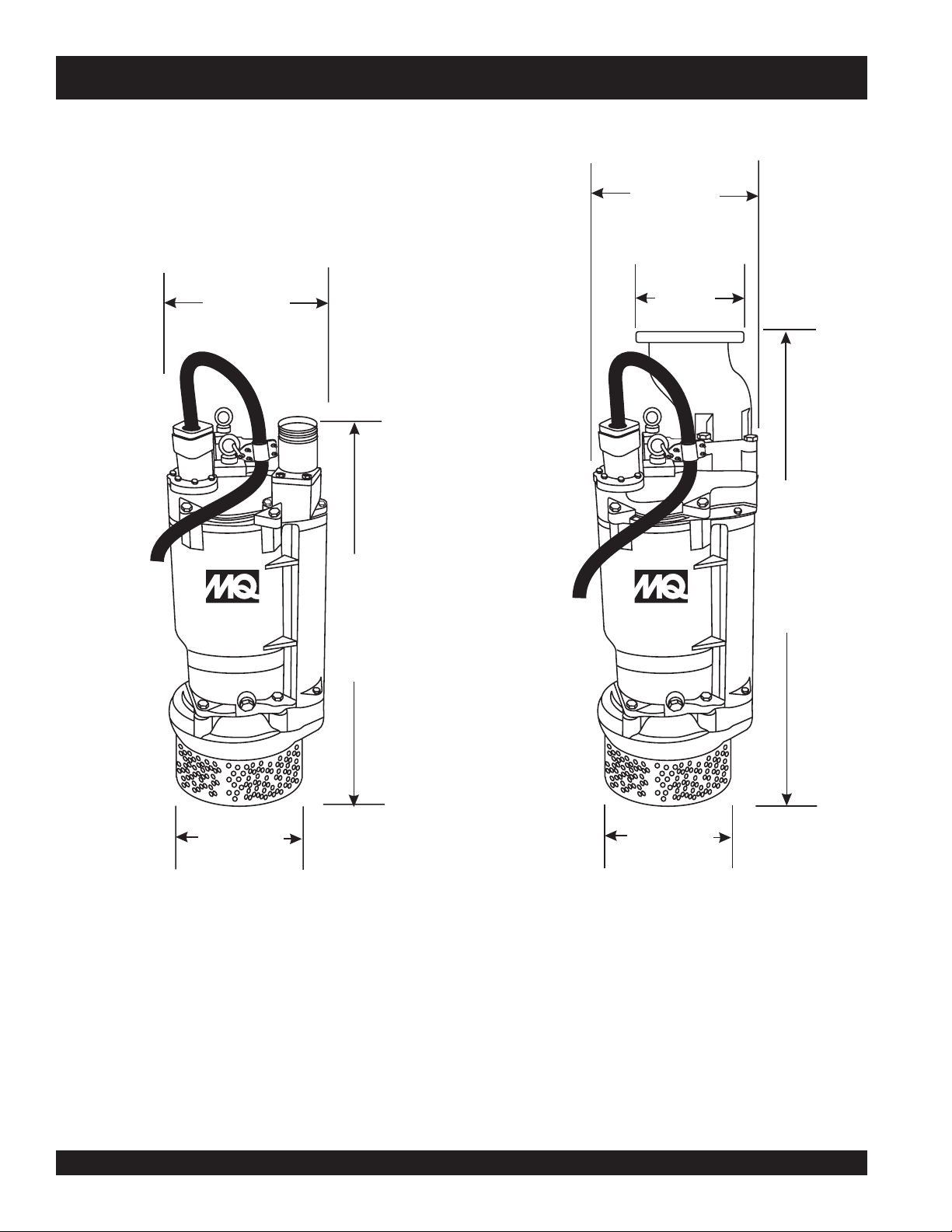
ST-4125D/ST-6125D — DIMENSIONS
13.5 in
(343 mm)
13.5 in
(343 mm)
ST-4125D
SUBMERSIBLE
PUMP
33.5 in
(851 mm)
11 in
(279 mm)
ST-6125D
SUBMERSIBLE
PUMP
39 in
(991 mm)
11.75 in
(298 mm)
11.75 in
(298 mm)
ST-4125D ST-6125D
Figure 1. Submersible Pump Dimensions
PAGE 8 — ST-4125D/ST-6125D SUBMERSIBLE PUMPS — OPERATION AND PARTS MANUAL — REV. #1 (06/12/08)
Page 9

ST-4125D/ST-6125D — SPECIFICATIONS
SNOITACIFICEPS.1ELBAT
ledoMD5214-TSD5216-TS
epyTpmuPelbisrembuSlagufirtneCpmuPelbisrembuSlagufirtneC
rellepmInorIelitcuDtsaCnorIeli
eziSegrahcsiD&noitcuS)mm15(.ni00.2)mm15(.ni00.2
yticapaCgnipmuPmumixaM
daeHxaM)sretem83(.tf521)sretem83(tf521
rewoP)wk5.7(PH01)wk
esahP/egatloVØ3064/032Ø3064/032
spmAgnitratS
spmAgninnuR
deriuqeRxoBlortnoC3etoNeeS3etoNeeS
htgneLelbaCrewoP)m2.51(.tf05)m2.51(.tf05
thgieWteNyrD)gk051(bl033)gk771(bl093
retil657,1(
etunim/snollag464
)etunim/s
)V032(941
)V064(57
)V032(72
)V064(41
tcuDtsaC
11(PH51
etunim/snollag016
)etunim/sretil903,2(
)V032(512
)V064(801
)V032(93
)V064(7.91
thgieH)mc1.38(ni7.23)mc6.89(ni8.83
retemaiD)mc63(ni2.41)mc63(ni2.41
1. Motor Rotation – Upon start-up, the pump "
counterclockwise (CCW) as viewed from the impeller end of the pump.
2. Mechanical Seal Oil – Use a good grade 10 weight non-detergent hydraulic oil (i.e. Shell Turbo 32 or equivalent). Fill oil cavity
75% to 85% full (allow air space for expansion).
3. Control Box - Control box (Table 2) is required for use to provide thermal overload protection to the pump.
kicks
" in the opposite direction of motor rotation. The correct rotation is
ST-4125D/ST-6125D SUBMERSIBLE PUMPS — OPERATION AND PARTS MANUAL — REV. #1 (06/12/08) — PAGE 9
Page 10

ST-4125D/ST-6125D — GENERAL INFORMATION
The Multiquip Model ST-4125D and ST-6125D submersible
pumps are designed to pump water. These pumps work best
when faced with high head applications where you need an
appreciable flow.
The ST-4125D and ST-6125D submersible pumps have dual
voltage, easily switched between 230 and 460 volts.
These pumps have a heavy-duty cast iron body that is very
durable and able to withstand rough handling. The ST-4125D
comes with NPT threads for standard hose connections while
the ST-6125D is equipped with 6-inch flange fittings.
The mechanical seal of these pumps operates within an oilfilled chamber that provides positive lubrication. This helps
prevent damage in the event the pump is run dry for short periods
of time.
PAGE 10 — ST-4125D/ST-6125D SUBMERSIBLE PUMPS — OPERATION AND PARTS MANUAL — REV. #1 (06/12/08)
Page 11

ST-4125D/ST-6125D — SUBMERSIBLE PUMP COMPONENTS
6
5
5
4
6
4
3
ST-4125D
SUBMERSIBLE
PUMP
2
1
7
1
8
ST-4125D
Figure 2. Submersible Pump Components
Figure 2 shows the location of the basic components, for
the ST-4125D and ST-6125D submersible pumps. Listed below
is a brief explanation of each component.
1. Strainer Base – This strainer base is made of stainless
steel which is resistant to hardware corrosion. For
dewatering purposes, always place the strainer base
on a platform.
2. Volute/Impeller – Impellers are constructed of cast
ductile iron to minimize wear and prolong service life.
3. Electric Motor – The ST-4125D pump utilizes a 60 Hz,
three-phase, 230/460 VAC, 10 HP electric motor and
the ST-6125D pump utilizes a 60 Hz, three-phase, 230/
460 VAC, 15 HP electric motor. Consult with a
electrician
Observe all city and local safety codes.
4. Discharge Port – Connect a 4-inch hose (ST-4125D)
or 6-inch hose (ST-6125D) to this port. Remember to
adequately support the discharge hose to avoid stress
on the pump.
before connecting motor to a power source.
licensed
5. AC Power Cable – These pumps are supplied with a
50 ft. (15.2 meters) AC power cable. Always check the
cable for signs of wear. NEVER use a defective power
cable. Replace the cable immediately if the cable is
worn or defective.
6. Eye Bolts – Always lift the submersible pump by the
eye bolts using a chain and lifting device capable of
lifting about 400 lbs. NEVER lift the pump by its power
cord! Lifting the pump by the power cord will cause
undue stress on the cord and ultimately the cord will
become dislodged from the pump.
7. Mechanical Seal Oil – This oil-filled seal provides
lubrication when running the pump dry. NEVER run the
pump dry! Running the pump dry will cause severe
damage to the pump.
8. Mechanical Seal Oil Plug – Remove this plug to
check and add hydraulic oil (Shell 32 or equivalent) to
the oil cavity. This oil protects the mechanical seal. Oil
cavity should be full enough to cover seal spring.
2
ST-6125D
SUBMERSIBLE
PUMP
ST-6125D
3
7
8
ST-4125D/ST-6125D SUBMERSIBLE PUMPS — OPERATION AND PARTS MANUAL — REV. #1 (06/12/08) — PAGE 11
Page 12

ST-4125D/ST-6125D — FLOAT SWITCHES
CAUTION!
HIGH
VOLTAGE!
CB12/14
Float Switch Theory
There is a tilt-sensitive mercury switch hermetically sealed within
each float. As the liquid level (water) rises or falls, the float changes
its angle until the mercury switch makes (close) or breaks (open)
the circuit.
The length of cord between the float and point of attachment
determines the amount of water to be pumped.
Float Switch (Dual)
Float switches (Figure 3) are used for the unattended operation
of the submersible pump. The ST-4125D and ST-6125D pumps
require the use of a control box to perform this function. Shown
in Figure 3 is an example of a dual float control switch application.
The Models ST-4125D and ST-6125D submersible pumps
require one each of the Model SW-1WOPA float type mercury
switches. These switches have a pumping range level between
5.5~18 feet (1.67~5.5 meters). All float switch connections are
Contact Multiquip sales department to order float switches.
bare wire (no plug). The ST-4125D/ST-6125D uses the
control box for 230V
EXTERNAL 3-PHASE
(230 OR 460 VOLT)
POWER SOURCE
CIRCUIT
BREAKER
L1
L2
L3
GROUND
RED
WHITE
BLACK
GREEN
ER
LOW
when float switches are required for the job application.
and the
CB14 control box for 460 V
CONTROL
BOX
CAUTION!
VOLTAGE!
RESET
CB12
HIGH
4 or 6-INCH
DISCHARGE
HOSE
ST-6125D
SUBMERSIBLE
PUMP
LIFTING
CHAIN
POWER
CORD
SUPPORT
PLATFORM
FLOAT
SWITCHES
PUMP
ON
PUMP
OFF
Figure 3. Dual Float Control Switch
PAGE 12 — ST-4125D/ST-6125D SUBMERSIBLE PUMPS — OPERATION AND PARTS MANUAL — REV. #1 (06/12/08)
Page 13

ST-4125D/ST-6125D — CONTROL BOXES
CAUTION!
HIGH
VOLTAGE!
CB12/14
Control Boxes
Control boxes (Figure 4) are required for remote control
and thermal shutdown capability for the submersible
pump.
These water-resistant control boxes provide electronic overload
protection, watertight housing and glands to prevent water from
leaking into the box, and a float switch interface.
Refer to Table 2 for the control box model that meets your
pumping requirements.
CAUTION!
HIGH
VOLTAGE!
MAN
OFF
AUTO
Contact Multiquip sales department to order control boxes as
listed in Table 2.
NOTE
xoBlortnoC
.oNledoM
21BCD5214-TS
ALWAYS
licensed electrician perform the
installation of the control box.
htiWdesU
have a qualified
ledoMpmuP
CAV032
epyTegatloV
esahP-eerhT
retaeH
eziS
76K72SEYSEYSEY
RESET
Figure 4. Electrical Control Box
(Model CB12/14)
snoitacificepSxoBlortnoC.2elbaT
daoLlluF
spmA
C/LU
AS
detsiL
lamrehT
daolrevO
noitcetorP
taolF
hctiwS
ytilibapaC
ST-4125D/ST-6125D SUBMERSIBLE PUMPS — OPERATION AND PARTS MANUAL — REV. #1 (06/12/08) — PAGE 13
21BCD521
6-TS
41BCD5214-TS
41BCD5216-TS
CAV032
esahP-eerhT
CAV064
esahP-eerhT
CAV064
esahP-eerhT
37K93SEYSEYSEY
65K41SEYSEYSEY
26K7.
91SEYSEYSEY
Page 14

ST-4125D/ST-6125D — CONTROL BOX INSTALLATION
DANGER - Hazardous VoltageDANGER - Hazardous Voltage
DANGER - Hazardous Voltage
DANGER - Hazardous VoltageDANGER - Hazardous Voltage
To place the ST-4125D/ST6125D
submersible pumps into operation
requires the use of a control box. The
control box contains the necessary
electronics (thermal overload module,
float switch connections and 230/460
voltage transformer) to operate the
pump. Remember this control box
contains hazardous voltages. Disconnect all sources of
power before installing or servicing. There exists the
possibility of electrocution, electric shock or burn, which can
cause severe bodily harm or even
CAUTION - InstallationCAUTION - Installation
CAUTION - Installation
CAUTION - InstallationCAUTION - Installation
This control box should only be installed or serviced by a
licensed electrician or qualified personnel.
CONTROL BOX MOUNTING
Mount the control box in an
the control box is securely fastened to a flat surface, that is free
of dust, dirt, moisture or any elements that may contaminate or
erode the electronic components of the control box.
3-Phase Power Installation (Input)
The ST-4125D/ST6125D submersible pump requires 230/
460V 3-phase power for normal operation. The pump is shipped
from the factory in the 230 VAC configuration. To change the
voltage setting from 230 VAC to 460 VAC refer to the
Selection
If you cannot determine what your pump's power
requirements are, look at the vendor supplied identification
name tag attached to the pump or please contact Multiquip's
Service/Technical Assistance department.
section.
upright vertical position
death
!
. Make sure
230/460 VAC
POWER CORD REQUIREMENTS
When routing the three phase power via a power cord to the
control box,
Table 3 below (Cord Length and Wire Size) to determine the
correct wire size. Incorrect wire size can adversely affect the
performance of the pump.
FLOAT SWITCH INSTALLATION
1. Remove the float switch input connector housing, then
route the float switch wires through the cable gland on the
control box. Attach the wires to the float switch terminal
block as indicated by Table 4. Refer to Figures 7 and 8.
ALWAYS
6GWA61GWA61GWA41
8GWA61GWA41GWA21
01GWA61GWA41GWA21
21GWA41GWA41GWA21
41GWA41GWA21GWA01
61GWA21GWA21GWA01
use the correct wire size. Please reference
SPMA.TF05.TF001.TF051
HCTIWSTAOLF
TRATS2DNA1SLANIMRET
EZISERIWDNAHTGNELDROC.3ELBAT
S
SNOITCENNOCHCTIWSTAOLF.4ELBAT S
LANIMRETHCTIWSTAOLF
REBMUNKCOLB
CAUTION - Voltage PhasingCAUTION - Voltage Phasing
CAUTION - Voltage Phasing
CAUTION - Voltage PhasingCAUTION - Voltage Phasing
Applying incorrect power (
submersible pump can cause severe damage to the pump.
Please make sure that the correct voltage and phase are
transferred to the pump at all times.
PAGE 14 — ST-4125D/ST-6125D SUBMERSIBLE PUMPS — OPERATION AND PARTS MANUAL — REV. #1 (06/12/08)
voltage phasing
) to the
2. Tighten the connector housing to ensure a tight fit between
the cord and the connector body. This will prevent the cable
from pulling out of the terminal block and also prevent
moisture from entering the control box.
3. Determine the length of the float switch wires, then secure
float switch wires to pump discharge hose.
POTS4DNA3SLAN
IMRET
Page 15

ST-4125D/ST-6125D — 230/460 VAC VOLTAGE SELECTION
230/460 VAC Voltage Selection
The ST-4125D/ST-6125D submersible pump is factory set
at 230 VAC. To change the voltage from 230 VAC to 460
VAC, perform the following (refer to Figure 5):
1. Place pump in a suitable area free of dirt and debris.
2. Remove the four retaining screws, using a 19 mm socket,
and the two Allen screws using an 8 mm socket, that secure
the pump casing.
3. Lift the top of the pump by attaching a chain on the eye
bolts and using a crane or similar equipment. Be careful
not to fully stretch the cable connections inside the pump.
4. Cut the tie-wrap holding the 460 VAC motor winding wires
as shown in Figure 5. Then remove the protective covering
from the wires (labeled 4, 5, and 6).
5. Remove the sleeving covering the large red wire and
separate the 2 wires labeled 1 and 7.
6. Connect the wire labeled 4 from step 4 to the wire labeled
7 from step 5 and join them with the large red wire. Cover
the wires with sleeving.
7. Repeat steps 5 and 6 for the large black wire and the large
white wire. Refer to the table in Figure 5 for wires to separate
(column 2) and wires to connect (column 4).
8. Using electrical tape, bind the 3 wires that were separated
and disconnected (labeled 1, 2, and 3). Place these wires
neatly inside the housing.
9. Reinstall the top of the pump and reinsert the six screws
and tighten securely.
CUT
TIE-WRAP
REMOVE PROTECTIVE
COVERING TO GAIN
ACCESS TO 460 VAC
WIRES 4, 5, AND 6.
REMOVE SLEEVING
230 VAC
MOTOR
WINDINGS
W
1
2
3
(LOW VOLTAGE)
X
Z
Y
STAR WITH
V
230 VAC
98U
MOTOR
WINDING
NEUTRAL
230 VAC
INPUT 3Ø
U (RED)
V (WHITE)
W (BLACK)
WHITE
WHITE
(LARGE)
(SMALL)
RED
BLACK
4
5
6
2
1
3
7
MOTOR WINDING CONFIGURATION
MOTOR
WINDINGS
1 AND 7
2 AND 8
3 AND 9
9
460 VAC
INPUT 3Ø
U (RED)
V (WHITE)
W (BLACK)
BLACK
(SMALL)
BLACK
(SMALL)
GREEN
8
7
4
5
6
9
8
7
Z
W
MOTOR
WINDINGS
4 AND 7
5 AND 8
6 AND 9
CONNECT
TO GROUND
SCREW IN
UPPER CASING
460 VAC
MOTOR
WINDINGS
230/460 VAC
MOTOR
WINDINGS
COMMON
460 VAC
(HIGH VOLTAGE)
U
X
7
MOTOR
8
Y
9
WINDING
STAR WITH
NEUTRAL
V
NOTE
PUMP IS SHIPPED FROM THE FACTORY FOR 230 VAC OPERATION.
FOR 460 VAC OPERATION SEE ABOVE WIRING ILLUSTRATION AND TABLE.
Figure 5. 230/460 VAC Pump Voltage Selection
ST-4125D/ST-6125D SUBMERSIBLE PUMPS — OPERATION AND PARTS MANUAL — REV. #1 (06/12/08) — PAGE 15
Page 16

ST-4125D/ST-6125D — CONTROL BOX WIRING DIAGRAM
EXTERNAL 3-PHASE
(230 OR 460 VOLT)
POWER SOURCE
CIRCUIT
BREAKER
L1
L2
L3
WHITE
BLACK
GROUND
RED
GREEN
CB-12/CB-14
POWER
INPUT
L1
L1
L2
L2
L3
L3
H1
F1
XF
FUSE
1/2 AMP
THREE PHASE WIRING
CONNECTIONS
M
RED AWG 8
RED AWG 8
RED AWG 8
H3
X1
BLK
H2
GRN
2
1
4
H4
CONTROL
TRANSFORMER
50VA CPT
WHT
X2
MAN
OFF
AUTO
O/L
HEATER SELECTION
OVERLOAD
NC
INDICATOR
RED
AWG 10
BLK
RED
WHT
SEE TABLE 2
FOR CORRECT
RELAY
O/L
X2
ON
LAMP
WHT
AWG 10
G
T1
T2
T3
PUMP
MOTOR
GRN
SELECTABLE 230 OR 460 VAC
VOLTAGE INPUTS
FUSE
X1
XF
120
115
X1
110
H4 H2 H3 H1
X2
JUMPER
TRANSFORMER
TAB
RED
AWG 10
NO
3
RED
AWG 10
4
43 2
STOP
FLOAT
SWITCH
START
FLOAT
SWITCH
L1 L2
230V INPUT
H2
H1
H3
H4
TERMINAL
1
CONTACTOR
5HP
M
A2
BLOCK
A1
L1 L2
460V INPUT
H3
H1
WHT AWG 10
H2
H4
CB-12
CB-14
Figure 7. Control Box Wiring Diagram
PAGE 16 — ST-4125D/ST-6125D SUBMERSIBLE PUMPS — OPERATION AND PARTS MANUAL — REV. #1 (06/12/08)
Page 17

ST-4125D/ST-6125D — 3-PHASE POWER INSTALLATION
3-PHASE POWER CORD (INPUT TO BOX) INSTALLATION
1. The three phase
input
power cord should have four wires.
Each wire is color coded. The colors are RED, WHITE,
BLACK and GREEN.
2. Remove the 3-phase AC input connector housing from the
control box, then route the three phase input power cable
through the cable gland on the control box. Attach the
wires to the AC terminal block inside the control box as
indicated by Table 5 and Figure 8.
SNOITCENNOCREWOPTUPNICAESAHP-3.5ELBAT
S
3-PHASE POWER INSTALLATION (OUTPUT TO PUMP)
1. The three phase
Each wire is color coded. The colors are RED, WHITE,
BLACK and GREEN.
2. Remove the 3-phase AC output power connector housing
on the control box, then route the three phase output power
cable through the cable gland on the control box. Attach
the wires to the AC terminal blocks on the
as indicated by Figure 8.
NOTE
ROLOCERIWELBAC#KCOLBLANIMRETCA
DER1L
ETIHW2L
KCALB3L
output
power cord should have four wires.
overload relay
Electrical connections to the power
source should only be performed by
licensed electrician
a
or qualified
personnel.
NEERGDNUORG
3. Tighten the connector housing to ensure a tight fit between
the power cord and the connector body. This will prevent
the cable from pulling out of the terminal block and also
prevent moisture from entering the control box.
It is recommended that the power being supplied to the control
ALWAYS
box
disconnect
of power from the control box in the event of an emergen
be connected to a
circuit breaker
or a
quick
switch. This safety feature allows for quick removal
cy.
4. Connect the other end of the 3-phase input power cord to
the voltage source. Remember to provide a means of
disconnecting the power from the control box (circuit breaker
or quick disconnect switch). Also make sure to provide a
good earth ground to the control box.
ST-4125D/ST-6125D SUBMERSIBLE PUMPS — OPERATION AND PARTS MANUAL — REV. #1 (06/12/08) — PAGE 17
Page 18

MOUNT CONTROL
BOX IN AN UP-LEFT
VERTICAL POSITION
CONTROLLER
AC POWER
TERMINAL BLOCK
FLOAT SWITCH
TERMINAL BLOCK
EXTERNAL 3-PHASE
(230 OR 460 VOLT)
POWER SOURCE
CIRCUIT
BREAKER
L1
L2
L3
WHITE
BLACK
AS SHOWN.
RED
GREEN
ST-4125D/ST-6125D — 3-PHASE POWER INSTALLATION
L
7
T
IS
0
R
(7
2
A
T
0
X
C
N
0
E
8
O
)
S
40
D
N
M
5
F
4
T
O
IC
2
7
R
L3
L1
1
1-
5
3
L2
2- 3-
4-
-3
-4
2- 3-
1-
2
T12T1
4-
4
T2
6
T3
AEG
L1L2L
R
E
S
E
BLACK
T
T
1
BLK RED WHT
3
1
2
4
L2
L3
L1
RED
BLK
WHITE
GRN
GROUND
FLOAT
SWITCH
INPUTS
R
-0
4
R
O
M
O
9
L
E
0
N
0
R
X
N
C
O
A
2
T.
.
B
I
m
0
p
U
.S
7
e
T
.
r
P
5
E
v
A
M
7
T
i
B
T
.
5
P
N
V
.
R
O
T
A
H3 H1
.
C
3516040
A
L
Z
.
N
1
(
R
1
3
50/60H
F
)
N
X
M
0
-
0
1
/
8
J
5
F
K
FUSE
C
D
UEL-ELE
Z
F
U
T
S
E
X
1
H
2
22
X
2
1
0
2
110
3
2
0
3
4
1
0
4
H4 H2
115
H
120
2
H
3
1
4
2
4
0
4
X
60
3
H
4
8
F
4
0
4
X
1
TRANSFORMER
OFF/ON
LAMP
6
1
3
0
L
L
3
2
3
M
A
I
N
T
R
I
P
T
T
3
2
1
/
2
0
5
0
3
-
0
2
MANUAL/AUTO
SWITCH
OVERLOAD
RELAY
HEATER
SEE TABLE 2
GRN
3 PHASE
AC OUTPUT
POWER CABLE
3 PHASE
AC INPUT
POWER CABLE
3. STOP FLOAT
SWITCH. CONNECT
TO TERMINALS 3 AND 4
1.SECURE FLOAT SWITCH
WIRES TO PUMP
DISCHARGE HOSE
2. START FLOAT
SWITCH. CONNECT
TO TERMINALS 1 AND 2
PUMPING
RANGE
WARNING
INSTALLATION OF THIS CONTROL
BOX IS TO BE PERFORMED ONLY BY
A LICENSED ELECTRICIAN OR
QUALIFIED PERSONNEL.
Figure 8. Three Phase
Control Box/Pump System Diagram
PAGE 18 — ST-4125D/ST-6125D SUBMERSIBLE PUMPS — OPERATION AND PARTS MANUAL — REV. #1 (06/12/08)
ST-6125D
SUBMERSIBLE
PUMP
Page 19

ST-4125D/ST-6125D — SETUP
Control Box Setup
1. From the voltage source set the circuit breaker or quick
disconnect switch to the ON position.
2. For manual operation of the pump, place the 3-position
operation switch (Figure 9) on the control box in the
MANUAL position.
Figure 9. Manual-Off-Auto SW. (Manual Position)
3. Verify that the ON indicator (Figure 10) on the control box
is LIT. This means that power is being supplied to the control
box.
Figure 10. Control Box Power ON Indicator
Reset
1. When the overload module detects an overload, the unit
will shut down. Check the unit and remove cause of overload.
2. Let the unit cool down and press the RESET button (see
Figure 12) on the front of the control box to reset the unit
(restore power).
Shut-Down
1. Place the 3-position operation switch on the control box to
the OFF position (Figure 13).
Figure 12. RESET Button
4. In the manual mode the pump will run continuously. Pay
close attention when running the pump in this mode.
DAMAGE to the pump may occur if pump is not immersed
in water.
5. To operate the pump automatically (float switches), place the
3-position operation switch in the AUTO position (Figure 11).
Figure 11. Manual-Off-Auto SW. (Auto Position)
6. In the AUTO mode the pump will run as long as there is a
sufficient amount of water. This amount is determined by
the setting of the float switches. The
contacts will open when the water level is low and power
will be removed from the pump's motor.
Once the water level has risen back to the appropriate
level the
will be restored to the pump's motor.
start float
switch contacts will close and power
stop float
switch
Figure 13. Manual-Off-Auto SW. (OFF Position)
2. Verify that the control box power ON light is OFF.
3. Turn the circuit breaker or quick disconnect switch to the
OFF position.
ST-4125D/ST-6125D SUBMERSIBLE PUMPS — OPERATION AND PARTS MANUAL — REV. #1 (06/12/08) — PAGE 19
Page 20

Operation
ST-4125D/ST-6125D — OPERATION
1. Attach a suitable lifting chain to the eye bolts (Figure 14) on
the pump and using a crane, or similar equipment, lower the
pump into place. For applications where there is an excessive amount of mud, grit or silt, the use of a support platform
is desirable.
ER
LOW
4 or 6-INCH
DISCHARGE
HOSE
LIFTING
CHAIN
CONNECT
TO CONTROL
BOX
POWER
CORD
2. Make sure the pump is always placed in an upright position,
not tilted (Figure 15). Never position the pump directly on a
soft, loose bottom. Remember to attain maximum pumping
capacity and prevent excessive wear, position the pump so
it will not burrow itself into sand or clay.
ER
LOW
SUPPORT
ST-6125D
SUBMERSIBLE
PUMP
PLATFORM
Figure 14. Placing the Submersible Pump
(Correct Upright Position)
3. After the pump has been positioned correctly into place,
CAUTION - Pump UseCAUTION - Pump Use
CAUTION - Pump Use
CAUTION - Pump UseCAUTION - Pump Use
DO NOT use this pump for swimming pool applications!
ST-6125D
SUBMERSIBLE
PUMP
Figure 15. Incorrect Tilted Position
power can be applied to the pump's electric motor.
PAGE 20 — ST-4125D/ST-6125D SUBMERSIBLE PUMPS — OPERATION AND PARTS MANUAL — REV. #1 (06/12/08)
Page 21

ST-4125D/ST-6125D — OPERATION
4. NEVER grab or touch a live power cord (Figure 16) with wet
hands, the possibility exists of
and even
tion
(POWER ON)
DANGER - Electrocution HazardDANGER - Electrocution Hazard
DANGER - Electrocution Hazard
DANGER - Electrocution HazardDANGER - Electrocution Hazard
death
.
POWER
CORD
Figure 16. Power Cord (Wet Hands)
electrical shock, electrocu-
WET
HANDS
Pump Shut-Down/Clean-up
1. Remove the power from the pump by turning off the circuit
breaker or switch that provides power to the pump. Remember to make sure that hands are dry (not wet), and feet are not
standing in water when removing disconnecting power from
the pump.
2. Using the chain and lifting crane, lift the pump up from its
current position. Remove the discharge hose from the discharge port on the pump.
3. Remove all power cables and float switches from the control
box. Place cables and float switches in a suitable container
where they will not get damaged.
4. If the pump was used to pump mud, grit or silt, flush vigorously
with clean water.
5. Remove the pump from the water. Wipe off any mud or debris
that might have attached itself to the pump.
6. Store pump in a clean dry place away from dirt and debris.
NEVER grab or touch a live power cord. DO NOT stand in
water when connecting the pump's power cord into a voltage
source. The possibility exist of electrical shock, electrocution
and possibly
3. If all of the pump's electrical requirements have been met,
insert the power plug on the pump into the power source
receptacle.
4. Wait a few seconds and water should begin to flow from the
discharge hose.
5. If water is not flowing from the discharge hose or not flowing
freely after a few minutes, remove the power from the pump
and check the system for leaks.
death!
ST-4125D/ST-6125D SUBMERSIBLE PUMPS — OPERATION AND PARTS MANUAL — REV. #1 (06/12/08) — PAGE 21
Page 22

ST-4125D/ST-6125D
—
MAINTENANCE
LUBRICATION
To check the oil level of the mechanical seal perform the
following:
5. If oil level is low fill with SAE 10 weight non-detergent
hydraulic oil (i.e. Shell Turbo 32 or equivalent). Fill oil cavity
75% to 85% full (allow air space for expansion). Pump oil
cavity capacity is approximately 180 cc.
1. Lay the pump (Figure 17) on its side with the oil plug facing
upwards.
2. Remove oil fill plug.
3. Visually inspect oil plug hole to verify that oil cavity is full
enough to cover seal spring. Check every 300 hours, change
hydraulic oil every 6 months (1,000 hours) or as needed.
IMPELLER
1. Make sure the clearance between the impeller and the
friction disk is approximately .012 - .020 inches (.304 - .508
mm.)
2. If impeller is defective or badly worn, replace impeller immediately.
4. While checking the hydraulic oil level, also check the
condition of the hydraulic oil in the seal cavity . Block the
opening with a finger and roll pump to one side to drain
oil into a small transparent container. If oil is cloudy or has
water in it, drain oil from pump cavity and replace hydraulic oil. Check the seal for wear damage.
REMOVE FILL PLUG, AND
VISUALLY INSPECT THAT
OIL CAVITY IS FULL ENOUGH
TO COVER SEAL SPRING.
FILL TO 75-80% CAPACITY
(APPROXIMATELY 180 CC.)
FILL WITH 10 WEIGHT NONDETERGENT HYDRAULIC
LAY PUMP FLAT
ON ITS SIDE
Figure 17. Checking Hydraulic Oil
PAGE 22 — ST-4125D/ST-6125D SUBMERSIBLE PUMPS — OPERATION AND PARTS MANUAL — REV. #1 (06/12/08)
OIL. USE SHELL TURBO 32
OR EQUIVALENT.
CHECK HYDRAULIC OIL
EVERY 300 HOURS. CHANGE
EVERY 6 MONTHS OR AS
NEEDED.
Page 23

ST-4125D/ST-6125D — TROUBLESHOOTING
Practically all breakdowns can be prevented by proper handling and maintenance inspections, but in the event of a
breakdown, use Table 6 (Pump Troubleshooting) as a basic guideline for troubleshooting the pump. If the problem cannot be
remedied, contact Multiquip's service department.
GNITOOHSELBUORTPMUP.6ELBAT
MOTPMYS MELBORPELBISSOP NOITULOS
.pmupehtotdeilppusgniebsi)Ø3064/032(egatlovreporptahtkcehC
?spma/egatlovtcerrocnI
.rekaerbtiucricecruosrewopkcehC.pmupeht
nurot)spma(tnerrucfotnuomaetauqedanasierehttahtkcehcoslA
?snoitcennoclacirtcelekcehC
?esufrewopnwolB
tratSoTsliaFpmuP
?esoh
revileDotsliaFpmuP
tuptuOlluF
liOlaeSniretaW
?dekcolrellepmI
?sgnidniwrotomteW
pmupdnarotomevitcefeD
?sgniraeb
?reniartspmupdeggolC .reniartsnaelC
?egatlovwoL
?nrowrellepmI .rellepmiecalpeR
?laesretawevitcefeD .laesretawecalpeR
?gulPlliFliOesooL .ylerucesnethgiT
naraelc
letamixorppaeb
.evitcefedfirotom
egrahcsiddetcirtserrodetsiwT
.htgnelderiuqerehtrofyticapac
.esufnwolbfoesuackcehc,esufecalpeR
.mehtyrdotsgnidniwekabdnarotompmup
.drocrewoptcepsni,gniriwkcehcsehctiwstaolfgnisufI
rellepmireporpmidnagniggolcrofkcehcdnadrocrewoptcennocsiD
.ecivednoitcetorpdaolrevokcehC.pmupgolcnU.ec
tsumecnatsisernoitalusnI.noitalusnirotomkcehcotretemitlumesU
elbmessasid,wolsiecnatsiserfI.smhoagem51y
ecalpeR.sgniraebecalpernrowfi,raewgniraebevissecxerofkcehC
.enilesohmorfgolcevomeR.deknik-nutalfesohyaL
egatloV.dezigrenesipmupelihwegatlovkcehcotretemtlovaesU
nafI.)daoldnadaolon(ecruosrewopkcehC.%01±nihtiwebtsum
gniyrrac-tnerrucetauqedasahtierusekam,desusidrocnoisnetxe
ST-4125D/ST-6125D SUBMERSIBLE PUMPS — OPERATION AND PARTS MANUAL — REV. #1 (06/12/08) — PAGE 23
Page 24

ST-4125D/ST-6125D — PERFORMANCE CURVES
140
120
100
80
60
60
Total Head (Feet)
40
20
ST4125D Performance Curve
TOTAL HEAD
Max 125 ft
CAPACITY
Max 464 G.P.M
140
120
100
80
60
60
Total Head (Feet)
40
20
0
100 200
300
400 500 600
Capacity(US.G.P.M)
ST6125D Performance Curve
TOTAL HEAD
Max 125 ft
CAPACITY
Max 610 G.P.M
0
100 200
300
400 500 600
Capacity(US.G.P.M)
Figure 18. Pump Performance Curves
PAGE 24 — ST-4125D/ST-6125D SUBMERSIBLE PUMPS — OPERATION AND PARTS MANUAL — REV. #1 (06/12/08)
Page 25

NOTES
ST-4125D/ST-6125D SUBMERSIBLE PUMPS — OPERATION AND PARTS MANUAL — REV. #1 (06/12/08) — PAGE 25
Page 26

EXPLANATION OF CODE IN REMARKS COLUMN
The following section explains the different symbols and
remarks used in the Parts section of this manual. Use the help
numbers found on the back page of the manual if there are any
questions.
The contents and part numbers listed in the parts section are
subject to change
guarantee the availibility of the parts listed.
Sample Parts List:
NO. PART NO. PART NAME QTY. REMARKS
1 12345 BOLT ...................... 1 ...... INCLUDES ITEMS W/
2
*
2*12347 WASHER, 3/8 IN. ... 1 ......
3 12348 HOSE ................... A/R .... MAKE LOCALLY
4 12349 BEARING ............... 1 ......S/N 2345B AND ABOVE
NO. Column
Unique Symbols - All items with same unique symbol
(*, #, +, %, or >) in the number column belong to the same
assembly or kit, which is indicated by a note in the “Remarks”
column.
Duplicate Item Numbers - Duplicate numbers indicate
multiple part numbers are in effect for the same general
item, such as different size saw blade guards in use or a
part that has been updated on newer versions of the same
machine.
When ordering a part that has more than one
item number listed, check the remarks column
for help in determining the proper part to order.
without notice
WASHER, 1/4 IN. .............
. Multiquip does not
NOT SOLD SEPARATELY
MQ-45T ONLY
*
QTY. Column
Numbers Used - Item quantity can be indicated by a
number, a blank entry, or A/R.
A/R (As Required) is generally used for hoses or other parts
that are sold in bulk and cut to length.
A blank entry generally indicates that the item is not sold
separately. Other entries will be clarified in the “Remarks”
Column.
REMARKS Column
Some of the most common notes found in the “Remarks”
Column are listed below. Other additional notes needed to
describe the item can also be shown.
Assembly/Kit
unique symbol will be included when this item is purchased.
Indicated by:
“INCLUDES ITEMS W/(unique symbol)”
Serial Number Break
number range where a particular part is used.
Indicated by:
“S/N XXXXX AND BELOW”
“S/N XXXX AND ABOVE”
“S/N XXXX TO S/N XXX”
Specific Model Number Use
used only with the specific model number or model number
variant listed. It can also be used to show a part is NOT
used on a specific model or model number variant.
Indicated by:
“XXXXX ONLY”
“NOT USED ON XXXX”
- All items on the parts list with the same
- Used to list an effective serial
- Indicates that the part is
“Make/Obtain Locally”
PART NO. Column
Numbers Used - Part numbers can be indicated by a
number, a blank entry, or TBD.
TBD (To Be Determined) is generally used to show a part
that has not been assigned a formal part number at time of
publication.
A blank entry generally indicates that the item is not sold
separately or is not sold by Multiquip. Other entries will be
clarified in the “Remarks” Column.
PAGE 26 — ST-4125D/ST-6125D SUBMERSIBLE PUMPS — OPERATION AND PARTS MANUAL — REV. #1 (06/12/08)
purchased at any hardware shop or made out of available
items. Examples include battery cables, shims, and certain
washers and nuts.
“Not Sold Separately”
purchased as a separate item and is either part of an
assembly/kit that can be purchased, or is not available for
sale through Multiquip.
- Indicates that the part can be
- Indicates that an item cannot be
Page 27

ST-4125D/ST-6125D — SUGGESTED SPARE PARTS
ST-4125D/ST-6125D
SUBMERSIBLE PUMP 1 TO 3 UNITS
Qty. P/N Description Remarks
1 1027620 KIT, MECHANICAL SEAL, SLEEVE, O-RINGS ST4125D
1 1027622 KIT, MECHANICAL SEAL, SLEEVE, O-RINGS ST6125D
ST-4125D/ST-6125D SUBMERSIBLE PUMPS — OPERATION AND PARTS MANUAL — REV. #1 (06/12/08) — PAGE 27
Page 28

ST-4125D SUBMERSIBLE PUMP ASSY.
1
ST-4125D — SUBMERSIBLE PUMP ASSY.
3
2
6
5
46
28
27
7
36
43
4
19
MECHANICAL
18
33
20
29
32
30
SEAL, SLEEVE,
O-RINGS KIT
22
50
23
21
45
44
35
39
42
40
38
31
37
49
48
41
47
16
9
10
8
12
13
15
26
11
17
34
14
25
PAGE 28 — ST-4125D/ST-6125D SUBMERSIBLE PUMPS — OPERATION AND PARTS MANUAL — REV. #1 (06/12/08)
Page 29

ST-4125D — SUBMERSIBLE PUMP ASSY.
ST-4125D SUBMERSIBLE PUMP ASSY.
NO PART NO PART NAME QTY. REMARKS
1 1025754 CABLE, POWER, 22 MM 50' 1
2 1042600 CABLE GLAND, DIA.38 1
3 ST4125D031 BOLT, M12X25L 2
4 1040546 CABLE BUSH, DIA.34 1
5 1042601 CABLE ENTRY ASSY. 1
6 ST4125D061 BOLT 7
7 1042602 MOULDING TUBE 1
8 1042604 VOLUTE, HOUSING 1
9 ST4125D0201 BOLT, M12X40L 1
10# ST4125D0204 O-RING, DIA.35X190 4
11 1042605 LOWER PACKING 1
12 1042607 IMPELLER 1
13 1042608 SUCTION COVER 1
14 ST4125D0221 BOLT, M12XM20L 4
15 1042609 STRAINER 1
16# ST4125D025 MECHANICAL SEAL 1
17 1040547 OIL SEAL 2
18 ST4125D032 HOSE CONNECTION, DISCHARGE 2" 1
19 ST4125D0321 BOLT, M10X25L 4
20# ST4125D0324 O-RING, DIA.3.1X105 1
21 1040548 OIL PLUG, M12 1
22 1042612 SEAL STOPPER 1
23 ST4125D0391 BOLT, M5X10L 3
25 1042613 BOTTOM PLATE 1
26 ST4125D0491 BOLT, M12X120L 3
27 1042614 MOTOR COVER 1
28 ST4125D0501 BOLT, M12X35L, M10X35L 6
29# ST4125D0504 O-RING, DIA.35X232 1
30 1042615 PACKING, UPPER 1
31 1042616 BALL BEARING, UPPER, #6306ZZC3 1
32 1042617 THERMAL PROTECTOR 3
33# TBD GASKET, FLANGE HOSE CONNECTION 1
34 1042618 NUT, IMPELLER, M20X2.5P 1
35 ST4125D055 ROTOR, UNIT 1
36 1042619 STATOR 1
37 1042620 BALL BEARING (LOWER)#6308/#7308 2
38 1042621 BEARING HOUSING, LOWER 1
39 ST4125D0601 BOLT, M8X20L 6
40# ST4125D0604 O-RING, DIA.3.1/135 1
41 1042623 BEARING COVER 1
42 ST4125D0611 BOLT, M6X16L 4
43 1042624 STATOR HOUSING 1
44 ST4125D0641 BOLT, M10X100L 2
45 1042625 KEY, 7X7X30 1
46 1042627 EYE BOLT, LIFTING,W3/4” 2
47 1033125 SEAL, LEAKAGE SENSOR 1
48 1040549 STOP RING 1
49 ST4125D0157 WAVE WASHER, DIA.55X70.5X0.4 1
50 1027620
KIT, MECHANICAL SEAL, SLEEVE, O-RINGS .......... 1 ...........INCLUDES ITEMS W/ #
ST-4125D/ST-6125D SUBMERSIBLE PUMPS — OPERATION AND PARTS MANUAL — REV. #1 (06/12/08) — PAGE 29
Page 30

ST-6125D SUBMERSIBLE PUMP ASSY.
1
ST-6125D — SUBMERSIBLE PUMP ASSY.
3
2
6
5
46
28
27
7
36
4
18
29
32
30
20
19
33
24
24
50
MECHANICAL
SEAL, SLEEVE,
O-RINGS KIT
23
21
45
43
44
35
42
38
39
37
40
31
49
48
41
47
22
16
9
10
8
12
13
15
26
11
17
34
14
25
PAGE 30 — ST-4125D/ST-6125D SUBMERSIBLE PUMPS — OPERATION AND PARTS MANUAL — REV. #1 (06/12/08)
Page 31

ST-6125D — SUBMERSIBLE PUMP ASSY.
ST-6125D SUBMERSIBLE PUMP ASSY.
NO PART NO PART NAME QTY. REMARKS
1 1035149 CABLE, POWER, 24 MM 50' 1
2 1042637 CABLE GLAND, DIA.38 1
3 ST6125D031 BOLT, M12X25L 2
4 1042638 CABLE BUSH, DIA.34 1
5 1042639 CABLE ENTRY ASSY. 1
6 ST6125D061 BOLT 7
7 1042640 MOULDING TUBE 1
8 1042641 VOLUTE, HOUSING 1
9 ST6125D02011 BOLT, M12X40L 1
10# ST6125D0204 O-RING, DIA.35X190 4
11 1042642 LOWER PACKING 1
12 1042643 IMPELLER 1
13 1042644 SUCTION COVER 1
14 ST6125D0221 BOLT, M12XM20L 4
15 1042645 STRAINER 1
16# ST6125D025 MECHANICAL SEAL 1
17 1042646 OIL SEAL 2
18 1042647 FLANGE, HOSE CONNECTION DISCHARGE 1
19 ST6125D0321 BOLT, M10X25L 4
20# ST6125D0324 O-RING, DIA.3.1X105 1
21 1042648 OIL PLUG, M12 1
22 1042649 SEAL STOPPER, (OPTIONAL) 1
23 ST6125D0391 BOLT, M5X10L 3
24 1042611 HOSE CONNECTION, DISCHARGE 1
25 1042650 BOTTOM PLATE 1
26 ST6125D0491 BOLT, BOTTOM PLATE, M12X120L 3
27 1042651 MOTOR COVER 1
28 ST6125D0501 BOLT, M12X35L, M10X35L 6
29# ST6125D0504 O-RING, DIA.35X232 1
30 1042652 UPPER PACKING 1
ST-4125D/ST-6125D SUBMERSIBLE PUMPS — OPERATION AND PARTS MANUAL — REV. #1 (06/12/08) — PAGE 31
Page 32

ST-6125D SUBMERSIBLE PUMP ASSY.
1
ST-6125D — SUBMERSIBLE PUMP ASSY.
3
2
6
5
46
28
27
7
36
4
18
29
32
30
20
19
33
24
24
50
MECHANICAL
SEAL, SLEEVE,
O-RINGS KIT
23
21
45
43
44
35
42
38
39
31
37
40
49
48
41
47
22
16
9
10
8
12
13
15
26
11
17
34
14
25
PAGE 32 — ST-4125D/ST-6125D SUBMERSIBLE PUMPS — OPERATION AND PARTS MANUAL — REV. #1 (06/12/08)
Page 33

ST-6125D — SUBMERSIBLE PUMP ASSY. (CONTINUED)
ST-6125D SUBMERSIBLE PUMP ASSY. (CONTINUED)
NO PART NO PART NAME QTY. REMARKS
31 1042653 BALL BEARING, UPPER, #6306ZZC3 1
32 1042617 THERMAL SENSOR 3
33# TBD GASKET, DISCHARGE CONNECTION 1
34 1042655 NUT, IMPELLER, M20X2.5P 1
35 1042654 ROTOR UNIT 1
36 1042663 STATOR 1
37 1042664 BALL BEARING, LOWER, #6308/#7308 2
38 1042665 BEARING HOUSING, LOWER 1
39 ST6125D0601 BOLT, M8X20L 6
40# ST6125D0604 O-RING, DIA.3.1/135 1
41 1042666 BEARING COVER 1
42 ST6125D0611 BOLT, M6X16L 4
43 1042667 STATOR HOUSING 1
44 ST6125D0641 BOLT, M10X100L 2
45 1042668 KEY, IMPELLER, 7X7X30 1
46 1042670 EYE BOLT, LIFTING, W3/4” 2
47 1033125 SEAL LEAKAGE SENSOR 1
48 1042671 STOP RING, S-40 1
49 ST6125D0157 WAVE WASHER, DIA.55X70.5X0.4 1
50 1027622 KIT, MECHANICAL SEAL, SLEEVE, O-RINGS .... 1 ....................INCLUDES ITEMS W/ #
ST-4125D/ST-6125D SUBMERSIBLE PUMPS — OPERATION AND PARTS MANUAL — REV. #1 (06/12/08) — PAGE 33
Page 34

TERMS AND CONDITIONS OF SALE — PARTS
PAYMENT TERMS
Terms of payment for parts are net 30 days.
FREIGHT POLICY
All parts orders will be shipped collect or
prepaid with the charges added to the invoice.
All shipments are F.O.B. point of origin.
Multiquip’s responsibility ceases when a signed
manifest has been obtained from the carrier,
and any claim for shortage or damage must be
settled between the consignee and the carrier.
MINIMUM ORDER
The minimum charge for orders from Multiquip
is $15.00 net. Customers will be asked for
instructions regarding handling of orders not
meeting this requirement.
RETURNED GOODS POLICY
Return shipments will be accepted and credit
will be allowed, subject to the following provisions:
1. A Returned Material Authorization must
be approved by Multiquip prior to shipment.
2. To obtain a Retur n Material Authorization,
a list must be provided to Multiquip Parts
Sales that defines item numbers, quantities, and descriptions of the items to be
returned.
a. The parts numbers and descriptions
must match the current parts price
list.
b. The list must be typed or computer
generated.
c. The list must state the reason(s) for
the return.
d. The list must reference the sales
order(s) or invoice(s) under which the
items were originally purchased.
e. The list must include the name and
phone number of the person requesting the RMA.
3. A copy of the Return Material Authoriza-
tion must accompany the return shipment.
4. Freight is at the sender’s expense. All
parts must be returned freight prepaid to
Multiquip’s designated receiving point.
5. Parts must be in new and resalable con-
6. The following items are not returnable:
7. The sender will be notified of any material
8. Such material will be held for five working
9. Credit on returned parts will be issued at
10. In cases where an item is accepted, for
11. Credit issued will be applied to future
PRICING AND REBATES
Prices are subject to change without prior
notice. Price changes are effective on a specific date and all orders received on or after that
date will be billed at the revised price. Rebates
for price declines and added charges for price
increases will not be made for stock on hand
at the time of any price change.
Multiquip reserves the right to quote and sell
dition, in the original Multiquip package (if
any), and with Multiquip part numbers
clearly marked.
a. Obsolete parts. (If an item is in the
price book and shows as being replaced by another item, it is obsolete.)
b. Any parts with a limited shelf life
(such as gaskets, seals, “O” rings,
and other rubber parts) that were purchased more than six months prior to
the return date.
c. Any line item with an extended dealer
net price of less than $5.00.
d. Special order items.
e. Electrical components.
f. Paint, chemicals, and lubricants.
g. Decals and paper products.
h. Items purchased in kits.
received that is not acceptable.
days from notification, pending instructions. If a reply is not received within five
days, the material will be returned to the
sender at his expense.
dealer net price at time of the original
purchase, less a 15% restocking charge.
which the original purchase document
can not be determined, the price will be
based on the list price that was effective
twelve months prior to the RMA date.
purchases only.
direct to Government agencies, and to Original
Equipment Manufacturer accounts who use
our products as integral parts of their own
products.
SPECIAL EXPEDITING SERVICE
A $35.00 surcharge will be added to the invoice
for special handling including bus shipments,
insured parcel post or in cases where Multiquip
must personally deliver the parts to the carrier.
LIMITATIONS OF SELLER’S LIABILITY
Multiquip shall not be liable hereunder for
damages in excess of the purchase price of the
item with respect to which damages are
claimed, and in no event shall Multiquip be
liable for loss of profit or good will or for any
other special, consequential or incidental dam-
ages.
LIMITATION OF WARRANTIES
No warranties, express or implied, are made
in connection with the sale of parts or trade
accessories nor as to any engine not manufac-
tured by Multiquip. Such warranties made in
connection with the sale of new, complete units
are made exclusively by a statement of war-
ranty packaged with such units, and Multiquip
neither assumes nor authorizes any person to
assume for it any other obligation or liability
whatever in connection with the sale of its
products. Apart from such written statement of
warranty, there are no warranties, express,
implied or statutory, which extend beyond the
description of the products on the face hereof.
Effective: February 22, 2006
PAGE 34 — ST-4125D/ST-6125D SUBMERSIBLE PUMPS — OPERATION AND PARTS MANUAL — REV. #1 (06/12/08)
Page 35

NOTES
ST-4125D/ST-6125D SUBMERSIBLE PUMPS — OPERATION AND PARTS MANUAL — REV. #1 (06/12/08) — PAGE 35
Page 36

OPERATION AND PARTS MANUAL
HERE’S HOW TO GET HELP
PLEASE HAVE THE MODEL AND SERIAL
NUMBER
UNITED STATES
Multiquip Corporate Office MQ Parts Department
18910 Wilmington Ave. Tel. (800) 421-1244 800-427-1244 Fax: 800-672-7877
Carson, CA 90746 Fax (800) 537-3927 310-537-3700 Fax: 310-637-3284
Contact: mq@multiquip.com
Mayco Parts Warranty Department
800-306-2926 Fax: 800-672-7877 800-421-1244, Ext. 279 Fax: 310-537-1173
310-537-3700 Fax: 310-637-3284 310-537-3700, Ext. 279
Service Department Technical Assistance
800-421-1244 Fax: 310-537-4259 800-478-1244 Fax: 310-631-5032
310-537-3700
MEXICO UNITED KINGDOM
MQ Cipsa Multiquip (UK) Limited Head Office
Carr. Fed. Mexico-Puebla KM 126.5 Tel: (52) 222-225-9900 Hanover Mill, Fitzroy Street, Tel: 0161 339 2223
Momoxpan, Cholula, Puebla 72760 Mexico Fax: (52) 222-285-0420 Ashton-under-Lyne, Fax: 0161 339 3226
Contact: pmastretta@cipsa.com.mx Lancashire OL7 0TL
CANADA BRAZIL
Multiquip Multiquip
4110 Industriel Boul. Tel: (450) 625-2244 Av. Evandro Lins e Silva, 840 - grupo 505 Tel: 011-55-21-3433-9055
Laval, Quebec, Canada H7L 6V3 Fax: (450) 625-8664 Barra de Tijuca - Rio de Janeiro Fax: 011-55-21-3433-9055
Contact: jmartin@multiquip.com Contact: cnavarro@multiquip.com.br, srentes@multiquip.com.br
ON-HAND
WHEN CALLING
Contact: sales@multiquip.co.uk
© COPYRIGHT 2008, MULTIQUIP INC.
Multiquip Inc and the MQ logo are registered trademarks of Multiquip Inc. and may not be used, reproduced, or altered without written permission. All other trademarks are
the property of their respective owners and used with permission.
This manual MUST accompany the equipment at all times. This manual is considered a permanent part of the equipment and should remain with the unit if resold.
The information and specifications included in this publication were in effect at the time of approval for printing. Illustrations, descriptions, references and technical data
contained in this manual are for guidance only and may not be considered as binding. Multiquip Inc. reserves the right to discontinue or change specifications, design or
the information published in this publication at any time without notice and without incurring any obligations.
Your Local Dealer is:
 Loading...