

Page 1

OPERATION AND PARTS MANUAL
Vibratory
Walk-Behind Roller
Model
MDR-9DYE
(Yanmar Diesel)
© COPYRIGHT 2003, MULTIQUIP INC.
Revision #0 (12/19/03)
MULTIQUIP INC
18910 WILMINGTON AVE. 800-427-1244
CARSON, CALIFORNIA 90746 FAX: 800-672-7877
310-537-3700
800-421-1244 800-478-1244
FAX: 310-537-3927 FAX: 310-631-5032
E-mail:mq@multiquip.com • www:multiquip.com
Atlanta • Boise • Dallas • Houston • Newark
Montreal, Canada • Manchester, UK
Rio De Janiero, Brazil • Guadalajara, Mexico
..
. PARTS DEPARTMENT:
..
SERVICE DEPARTMENT/TECHNICAL ASSISTANCE:
Page 2
PAGE 2 — MQ-MIKASA MDR-9DYE VIBRATORY ROLLER — PARTS & OPERATION MANUAL — REV. #0 (12/19/03)
Page 3

HERE'S HOW TO GET HELP
PLEASE HAVE THE MODEL AND SERIAL
NUMBER
MULTIQUIP’S MAIN PHONE NUMBERS
800-421-1244 FAX: 310-537-3927
310-537-3700
PARTS DEPARTMENT
800-427-1244 FAX: 800-672-7877
310-537-3700 FAX: 310-637-3284
MAYCO PARTS
800-306-2926 FAX: 800-672-7877
310-537-3700 FAX: 310-637-3284
SERVICE DEPARTMENT
800-478-1244 FAX: 310-537-4259
310-537-3700
MQ POWER SERVICE DEPARTMENT
800-835-2551 FAX: 310-638-8046
ON-HAND
WHEN CALLING
310-537-3700
TECHNICAL ASSISTANCE
800-478-1244 FAX: 310-631-5032
WARRANTY DEPARTMENT
800-421-1244, EXT. 279 FAX: 310-537-1173
310-537-3700, EXT. 279
MQ-MIKASA MDR-9DYE VIBRATORY ROLLER — PARTS & OPERATION MANUAL — REV. #0 (12/19/03) — PAGE 3
Page 4
TABLE OF CONTENTS
MIKASA MDR-9DYEVIBRATORY ROLLER
Proposition 65 Warning ..............................................2
Here's How To Get Help .............................................3
Table Of Contents ......................................................4
Parts Ordering Procedures ........................................ 5
Safety Message Alert Symbols .............................. 6-7
Rules for Safe Operation ....................................... 8-9
Operation and Safety Decals ...................................10
Specifications ...........................................................11
Dimensions ..............................................................12
General Information ........................................... 14-15
Vibratory Roller Components ................................... 16
Yanmar Engine Components ...................................17
Inspection .......................................................... 18-19
Operation ........................................................... 21-23
Maintenance ...................................................... 24-29
Troubleshooting ................................................. 30-31
Explanation Of Code In Remarks Column ...............32
Suggested Spare Parts ............................................33
Yanmar L100EEDEVMK2 Engine
Cylinder Block Assembly ....................................66-67
Cylinder Head and Cover Assembly ..................68-69
Muffler Assembly ............................................... 70-71
Air Cleaner Assembly .........................................72-73
Crankshaft, Piston and Camshaft Assembly .....74-75
Lub. Oil Pump and Governor Assembly .............76-77
Cooling and Starting Device Assembly .............. 78-79
Fuel Injection Pump Assembly ...........................80-81
Fuel Tank and Fuel Line Assembly ....................82-83
Starting Motor and Dynamo Assembly ..............84-85
Tool Label and Gasket Set Assembly ................86-87
Terms and Conditions Of Sale — Parts .................. 88
PARTS ILLUSTRATIONS
Decal Placement ................................................ 34-35
Body Assembly .................................................. 36-37
Front Cover Assembly ........................................ 38-41
Axle Assembly .................................................... 42-45
Transmission Assembly ...................................... 46-47
Hydraulic Oil Tank Assembly ............................. 48-49
Clutch Box Assembly ......................................... 50-53
Vibrator Assembly .............................................. 54-55
Upper Control Handle Assembly........................ 56-59
Lower Control Handle Assembly........................ 60-61
Battery Assembly ............................................... 62-63
Ignition Switch/Mounting Plate Assembly .......... 64-65
NOTE
Specification and part
number are subject to
change without notice.
PAGE 4 — MQ-MIKASA MDR-9DYE VIBRATORY ROLLER — PARTS & OPERATION MANUAL — REV. #0 (12/19/03)
Page 5

PARTS ORDERING PROCEDURES
When ordering parts,
please supply the following information:
❒❒
❒ Dealer account number
❒❒
❒❒
❒ Dealer name and address
❒❒
❒❒
❒ Shipping address (if different than billing address)
❒❒
❒❒
❒ Return fax number
❒❒
❒❒
❒ Applicable model number
❒❒
❒❒
❒ Quantity, part number and description of each part
❒❒
❒❒
❒ Specify preferred method of shipment:
❒❒
✓ FedEx or UPS Ground
✓ FedEx or UPS Second Day or Third Day
✓ FedEx or UPS Next Day
✓ Federal Express Priority One
✓ DHL
✓ Tr u c k
Note: Unless otherwise indicated by customer, all
orders are treated as “Standard Orders”, and will
ship within 24 hours. We will make every effort to
ship “Air Shipments” the same day that the order is
received, if prior to 2PM west coast time. “Stock
Orders” must be so noted on fax or web forms.
Here’s how to get help...
Please have the model and serial number on
hand when calling.
Parts Department
800-427-1244 Fax: 800-672-7877
310-537-3700 Fax: 310-637-3284
Mayco Parts
800-306-2926 Fax: 800-672-7877
310-537-3700 Fax: 310-637-3284
Service Department
800-478-1244 Fax: 310-537-4259
310-537-3700
MQ Power Service Department
800-835-2551 Fax: 310-638-8046
310-537-3700
Technical Assistance
800-478-1244 Fax: 310-631-5032
Warranty Department
800-421-1244, Ext. 279 Fax: 310-537-1173
310-537-3700, Ext. 279
Multiquip’s Main Phone Numbers
800-421-1244 Fax: 310-537-3927
310-537-3700
Place Your Parts Order Via Web or Fax
For Even More Savings!
Extra Discounts!
All parts orders which include complete part numbers
and are received by our automated web parts order
system, or by fax qualify for the following extra
discounts:
Ordered Standard Stock orders
via orders ($750 list and above)
Fax 3% 10%
Web 5% 10%
Special freight allowances
when you order 10 or more
line items via Web or Fax!**
FedEx Ground Service
No other allowances on freight shipped by any other
carrier.
NOTE: DISCOUNTS ARE SUBJECT TO CHANGE
at no charge for freight
MULTIQUIP INC.
18910 WILMINGTON AVENUE
POST OFFICE BOX 6254
CARSON, CALIFORNIA 90749
310-537-3700 • 800-421-1244
FAX: 310-537-3927
E-MAIL: mq@multiquip.com
WWW: multiquip.com
MQ-MIKASA MDR-9DYE VIBRATORY ROLLER — PARTS & OPERATION MANUAL — REV. #0 (12/19/03) — PAGE 5
Direct TOLL-FREE access
to our Parts Department:
Toll-free nationwide — 800-427-1244
Page 6
MDR-9DYE — SAFETY MESSAGE ALERT SYMBOLS
FOR YOUR SAFETY AND THE SAFETY OF OTHERS!
Safety precautions should be followed at all times when
operating this equipment. Failure to read and understand the
Safety Messages and Operating Instructions could result in
injury to yourself and others.
This Owner's Manual has
been developed to provide
complete instructions for the
NOTE
Before using this vibratory roller, ensure that the operating
individual has read and understands all instructions in this
manual.
safe and efficient operation
of the Multiquip Model
MDR-9DYE Vibration Roller.
Refer to the engine
manufacturer’s instructions for
data relative to its safe
operation.
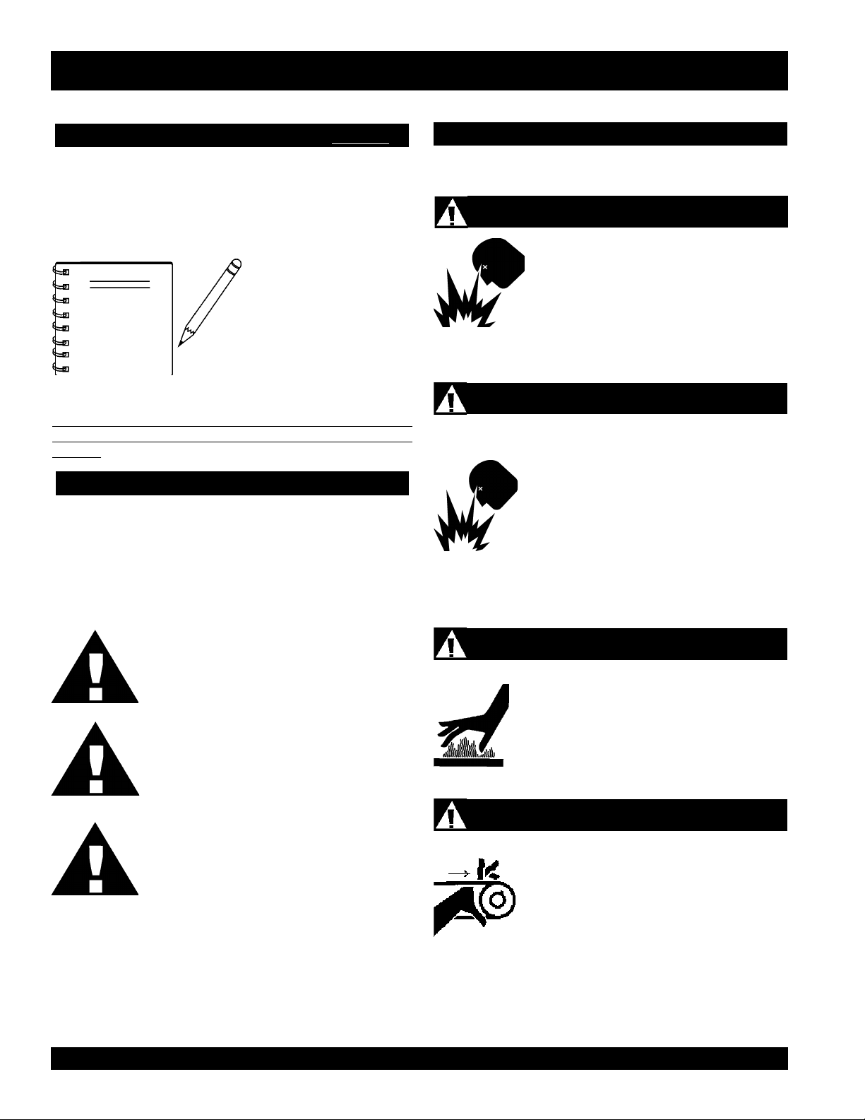
HAZARD SYMBOLS
SAFETY MESSAGE ALERT SYMBOLS
The three (3) Safety Messages shown below will inform you
about potential hazards that could injure you or others. The
Safety Messages specifically address the level of exposure to
the operator, and are preceded by one of three words: DANGER,
WARNING, or CAUTION.
L
Lethal Exhaust Gases
Engine exhaust gases contain poisonous
carbon monoxide. This gas is colorless and
odorless, and can cause death if inhaled.
NEVER operate this equipment in a confined
area or enclosed structure that does not
provide ample free flow air.
Explosive Fuel
Diesel fuel
vapors can cause an explosion if ignited. DO
NOT start the engine near spilled fuel or
combustible fluids. DO NOT fill the fuel tank
while the engine is running or hot. DO NOT
overfill tank, since spilled fuel could ignite if it
comes into contact with hot engine parts or
sparks from the ignition system. Store fuel in
approved containers, in well-ventilated areas
and away from sparks and flames. NEVER
use fuel as a cleaning agent.
is extremely flammable, and its
DANGER: You WILL be KILLED or
SERIOUSLY injured if you do not follow
directions.
WARNING: You CAN be KILLED or
SERIOUSLY injured if you do not follow
directions.
CAUTION: You CAN be injured if you
do not follow directions.
Potential hazards associated with this vibratory roller operation
will be referenced with Hazard Symbols which appear
throughout this manual, and will be referenced in conjunction
with Safety Message Alert Symbols.
Burn Hazards
Engine components can generate extreme heat.
To prevent burns, DO NOT touch these areas
while the engine is running or immediately after
operations. Never operate the engine with heat
shields or heat guards removed.
Rotating Parts
NEVER operate equipment with covers, or
guards removed. Keep fingers, hands, hair and
clothing away from all moving parts to prevent
injury.
PAGE 6 — MQ-MIKASA MDR-9DYE VIBRATORY ROLLER — PARTS & OPERATION MANUAL — REV. #0 (12/19/03)
Page 7

MDR-9DYE — SAFETY MESSAGE ALERT SYMBOLS
Accidental Starting
ALWAYS place the engine ON/OFF switch in
the OFF position, when the vibration roller is
not in use.
Sight and Hearing hazard
ALWAYS wear approved eye and
hearing protection.
Respiratory Hazard
ALWAYS wear approved respiratory
protection.
Equipment Damage Messages
Other important messages are provided throughout this manual
to help prevent damage to your vibration roller, other property,
or the surrounding environment.
NOTE
This vibratory roller, other
property, or the surrounding
environment could be
damaged if you do not follow
instructions.
MQ-MIKASA MDR-9DYE VIBRATORY ROLLER — PARTS & OPERATION MANUAL — REV. #0 (12/19/03) — PAGE 7
Page 8
CAUTION:
MDR-9DYE — RULES FOR SAFE OPERATION
Failure to follow instructions in this manual
may lead to serious injury or even death! This
equipment is to be operated by trained and
qualified personnel only! This equipment is
for industrial use only.
The following safety guidelines should always be used when
operating the MIKASA MDR-9DYE Vibratory Roller.
GENERAL SAFETY
■
DO NOT operate or service this equipment before
reading this entire manual.
■
This equipment should not be operated by
persons under 18 years of age.
■
NEVER operate this equipment without proper
protective clothing, shatterproof glasses, steeltoed boots and other protective devices required
by the job. ALWAYS wear slip resistant safety
shoes or boots.
■
NEVER operate this equipment when not feeling
well due to fatigue, illness or taking medicine.
■
NEVER operate this equipment under the
influence or drugs or alcohol.
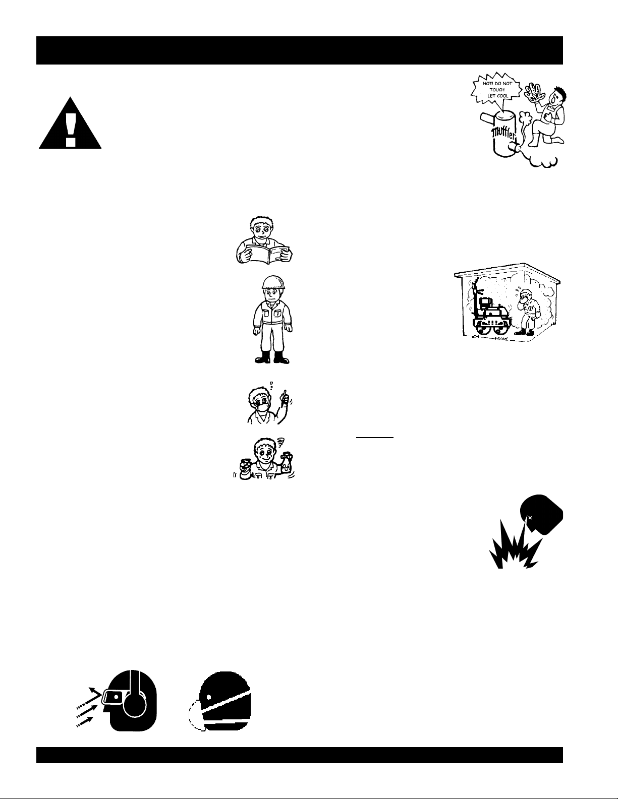
■
NEVER touch the hot exhaust manifold,
muffler or cylinder. Allow these parts to
cool before servicing engine or vibratory
roller.
■
High Temperatures – Allow the engine to cool before adding
fuel or performing service and maintenance functions. Contact
hot
with
■
The engine of this vibratory roller requires an adequate free
flow of cooling air. NEVER operate the vibratory roller in any
enclosed or narrow area where free flow of the air is restricted.
If the air flow is restricted it will
cause serious damage to the
vibratory roller or engine and
may cause injury to people and
property. Remember the roller’s
engine gives off DEADLY gases.
■
ALWAYS refuel in a well-ventilated area, away from sparks
and open flames.
■
ALWAYS use extreme caution when working with flammable
liquids. When refueling, stop the engine and allow it to cool.
DO NOT
explosion could result from fuel vapors, or if fuel is spilled on
a hot engine.
components can cause serious burns.
smoke around or near the machine. Fire or
■
NEVER operate the vibratory roller in an explosive
■
NEVER use accessories or attachments, which are not
recommended by Multiquip for this equipment. Damage to
the equipment and/or injury to user may result.
atmosphere or near combustible
materials. An explosion or fire could
result causing severe
bodily harm or
even death.
■
Manufacturer does not assume responsibility for any accident
due to equipment modifications.
■
Whenever necessary, replace nameplate, operation and
safety decals when they become difficult read.
■
ALWAYS wear proper respiratory (mask), hearing and eye
protection equipment when operating the vibratory roller.
PAGE 8 — MQ-MIKASA MDR-9DYE VIBRATORY ROLLER — PARTS & OPERATION MANUAL — REV. #0 (12/19/03)
■
Topping-off to filler port is dangerous, as
it tends to spill fuel.
■
ALWAYS store the vibratory roller in a clean, dry location out
of the reach of children.
■
NEVER run engine without air cleaner. Severe engine
damage may occur.
■
NEVER leave the vibratory roller unattended, turn off engine.
■
CAUTION must always be observed while servicing this
vibratory roller. Rotating parts can cause injury if contacted.
■
DO NOT leave vibratory roller with engine running. Use
chock blocks if parking
vibratory roller on a grade.
Page 9
MDR-9DYE — RULES FOR SAFE OPERATION
■
NEVER disconnect any
These devices are intended for operator safety. Disconnection
of these devices can cause severe injury, bodily harm or even
death! Disconnection of any of these devices will void all
warranties.
Loading and Unloading (Crane)
■
Before lifting, make sure that machine parts (hook and
vibration insulator) are not damaged and screws are not
loosened or lost.
■
Always make sure crane or lifting device has been properly
secured to the hook of guard frame on vibratory roller.
■
NEVER lift the machine while the engine is running.
■
Use adequate lifting cable (wire or rope) of sufficient strength.
■
Use one point suspension hook and lift straight upwards.
■
NEVER allow any person or animal to stand underneath the
machine while lifting.
■
Try not to lift machine to unnecessary heights.
Transporting
"emergency or safety devices"
.
■
■
In emergencies
nearest phone or
Also know the phone numbers of the nearest
ambulance, doctor
information will be invaluable in the case of an
emergency.
ALWAYS know the location of the nearest and
always
know the location of the
keep a phone on the job site
and
fire department
. This
first aid kit
.
.
■
Always shutdown engine before transporting.
■
Tighten fuel tank cap securely and close fuel cock to prevent
fuel from spilling.
■
Drain fuel when transporting vibratory roller over long
distances or bad roads.
■
Always tie-down the vibratory roller during transportation by
securing the roller's guard frame with rope.
Emergencies
■
ALWAYS know the location of the nearest
fire extinguisher
Maintenance Safety
.
■
■
■
■
■
NEVER lubricate components or attempt service on a
running machine.
ALWAYS allow the machine a proper amount of time to
cool before servicing.
Keep the machinery in proper running condition.
Fix damage to the machine immediately and always replace
broken parts.
Dispose of hazardous waste properly. Examples of
potentially hazardous waste are used motor oil, fuel and
fuel filters.
■
DO NOT use food or plastic containers to dispose of
hazardous waste.
■
DO NOT pour waste, oil or fuel directly onto the ground,
down a drain or into any water source.
MQ-MIKASA MDR-9DYE VIBRATORY ROLLER — PARTS & OPERATION MANUAL — REV. #0 (12/19/03) — PAGE 9
Page 10
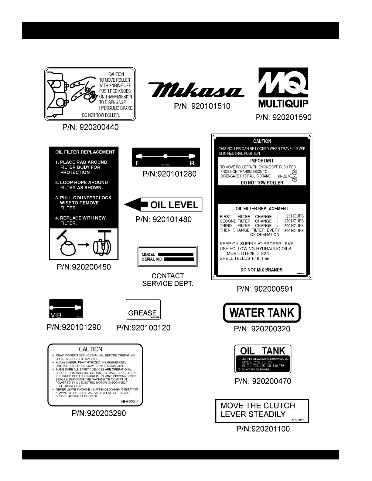
MDR-9DYE — OPERATION AND SAFETY DECALS
Figure 1 displays the operation and safety decals as they appear on the vibratory roller. Should any of these decals become
damaged or unreadable, contact the Multiquip Parts Department for a replacement set.
Figure 1. Operation and Safety Decals
PAGE 10 — MQ-MIKASA MDR-9DYE VIBRATORY ROLLER — PARTS & OPERATION MANUAL — REV. #0 (12/19/03)
Page 11
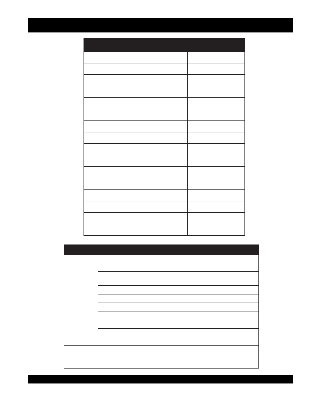
MDR-9DYE — SPECIFICATIONS
.1elbaTRELLORYROTARBIVEYD9-RDMSNOITACIFICEPS
ecroFlagufirtneC )gk000,3(.sbl006,6
ycneuqerFnoitarbiVmpv000,3
)esreverdnadrawrof(deepSgnilevarT )rh/mk3ot0(hpm8.1ot0
ytilibAedarG°52
relloRfohtdiWxretemaiD )mc007x754(ni6.72x81
esaBleehW )mm075(ni4.22
ecnaraelCdaoRediS )mm472(ni8.01
)eldnaHhtiw(htgneL )mm048,2(ni8.111
htdiW )mm597(ni3.13
thgieH )mm021,1(ni1.44
thgieWlatoT )gk088(.sbl049,1
noituloveRtupnIgnikroWmpr000,2
erusserPdetaRsuounitnoC mc/gk501(isp005,1
yticapaCknaTliO )sretil51(snollag4
yticapaCknaTretaW )sretil32(snollag6
ytilibAgnikroWm001,2
2
rh/
2
)
SNOITACIFICEPSENIGNE.2elbaT
ledoM 2KMVED-EE001LRAMNAY
epyT aenignEleseiD,rednilyCelgniS,ekorts4delooc-riA
ekortSXeroB
tnemecalpsiDmc604(ni-uc77.42
enignE
tuptuOxaM.M.P.R0063/.P.H0.01
yticapaCknaTleuF)sretil5.5(snollag54.1
leuF2#leseiD
yticapaCliOebuL)sretil56.1(strauq57.1
metsyStrelAliOseY
dohteMgnitratStratSlioceR/cirtcelE
.ni57.2X.ni64.3
).mm07xmm88(
3
)
noisnemiD
)HxWxL(
thgieWteNyrD
.ni4.91X5.81x4.61
).mm494X074X714(
).gK35(.sbl6.611
MQ-MIKASA MDR-9DYE VIBRATORY ROLLER — PARTS & OPERATION MANUAL — REV. #0 (12/19/03) — PAGE 11
Page 12
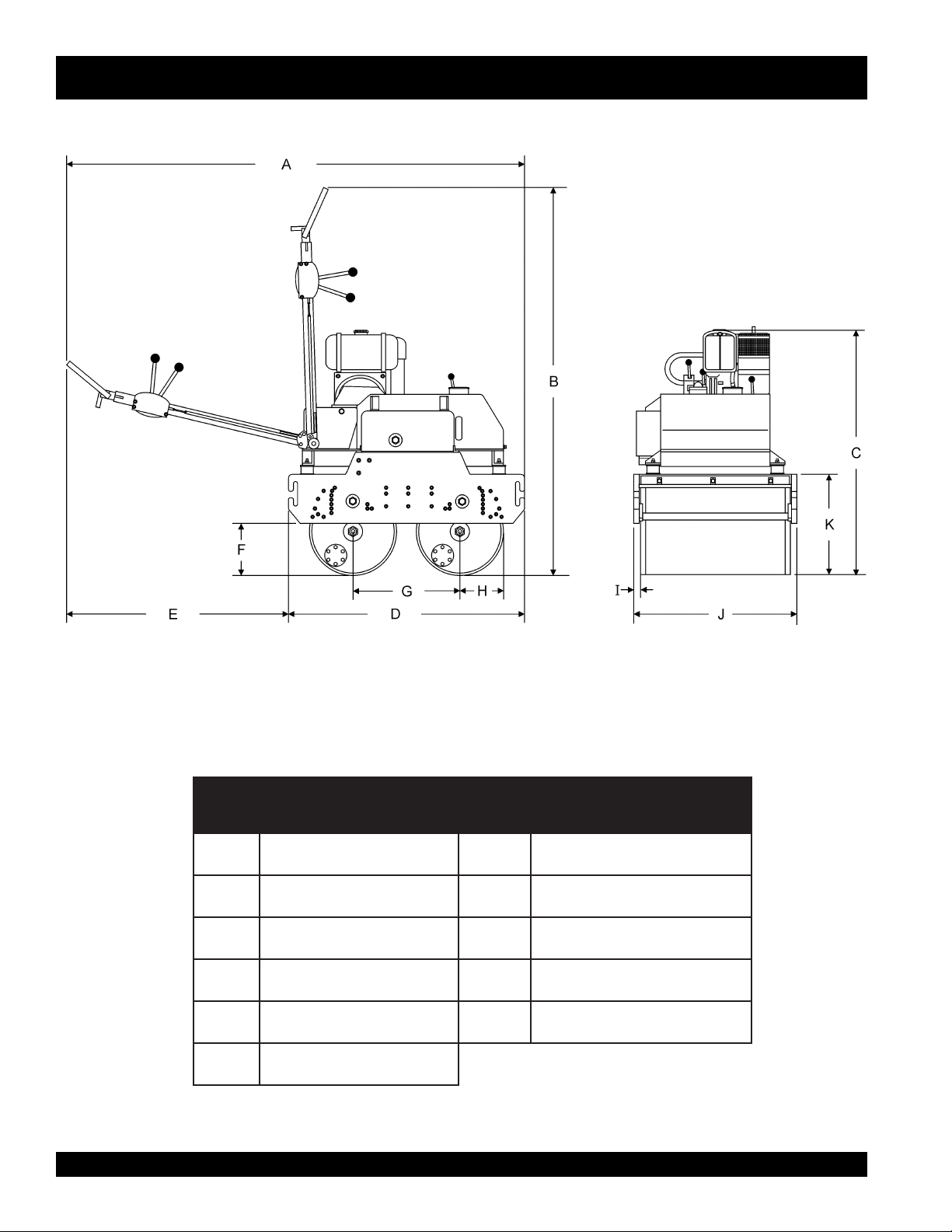
MDR-9DYE — DIMENSIONS
Figure 2. MDR-9DYE Vibratory Roller Dimensions
.FERSNOISNEMID.FERSNOISNEMID
A)sretem8.2(.ni8.111F )sretem75.(.ni4.22
B)sretem32.2(.ni88G )sretem754.(.ni81
C)sretem71.1(.ni64
D)sretem61.1(.ni9.54
E)sretem972.(.ni11
H
I
SNOISNEMIDRELLOR.3ELBAT
)sretem283.(.ni5.51
)sretem731.(.ni4.5
PAGE 12 — MQ-MIKASA MDR-9DYE VIBRATORY ROLLER — PARTS & OPERATION MANUAL — REV. #0 (12/19/03)
Page 13

NOTE PAGE
MQ-MIKASA MDR-9DYE VIBRATORY ROLLER — PARTS & OPERATION MANUAL — REV. #0 (12/19/03) — PAGE 13
Page 14
MDR-9DYE — GENERAL INFORMATION
The Mikasa Model MDR-9DYE is a powerful compacting tool
capable of applying a tremendous force in consecutive impacts
to a soil surface. With 28-inch drums and 32 inches overall width,
virtually any asphalt or mixed granular soil compaction job is
quickly cut down to size.
The impact force of the MDR-9DYE levels and uniformly
compacts voids between soil particles to increase dry density.
Features include:
Hydraulic variable speed transmission assures easy
handling.
Deadman device which when pressed or hit will
cause the travel lever to return to neutral position
bringing the machine to a stop.
Non-corrosive water tank for the sprinkler system with a
capacity of 6 gallons.
Simple dual-lever controls assure operator safety and
convenience.
Sight gauge for hydraulic oil tank.
Front -mounted auxiliary travel lever.
Four large rubber shock mounts minimize vibrations to the
engine and hydraulics.
FREQUENCY/SPEED
The vibrating roller maximum frequency is 3000 vpm (vibrations
per minute). The forward and reverse travel speed of the vibratory
roller is approximately 1.8 mph (3 km/hour).
ENGINE
The Mikasa MDR-9DYE Vibratory Roller is equipped with a
YANMAR L100EE-DEVMK2.
CONTROLS
Before starting the MDR-9DYE Vibratory Roller, identify and
understand the function of the controls and components as
indicated in Figure 6.
TRANSPORTATION
Adjustable transport hooks allow an operator to place the roller
on the tailgate of a dump truck without any assistance. The
control handle of the MDR-9DYE Vibratory Roller can be folded
vertically for ease of transport and storage.
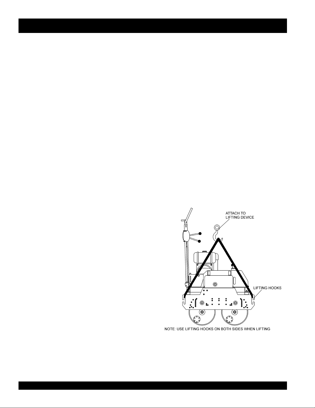
LIFTING THE ROLLER
When lifting of the roller is required (Figure 3), attach a suitable
hook or shackle to the
lifting device is capable of lifting 1,940 lbs (880 kg).
lifting hooks
of the roller. Make sure the
Convenient tie-downs, front and rear.
Scraper Bar.
Drum sprinkler system.
Handle folds to 90 degrees for storage and transport..
Figure 3. Lifting The Roller
PAGE 14 — MQ-MIKASA MDR-9DYE VIBRATORY ROLLER — PARTS & OPERATION MANUAL — REV. #0 (12/19/03)
Page 15
MDR-9DYE — GENERAL INFORMATION
CAUTION :
NEVER! stand under, or get onto the roller
while it is being lifted or moved.
CAUTION :
CAUTION :
NEVER! use any other part of the roller for
lifting purposes. Use the lifting eye. Using other
parts of the roller for lifting will cause severe
damage to the roller,
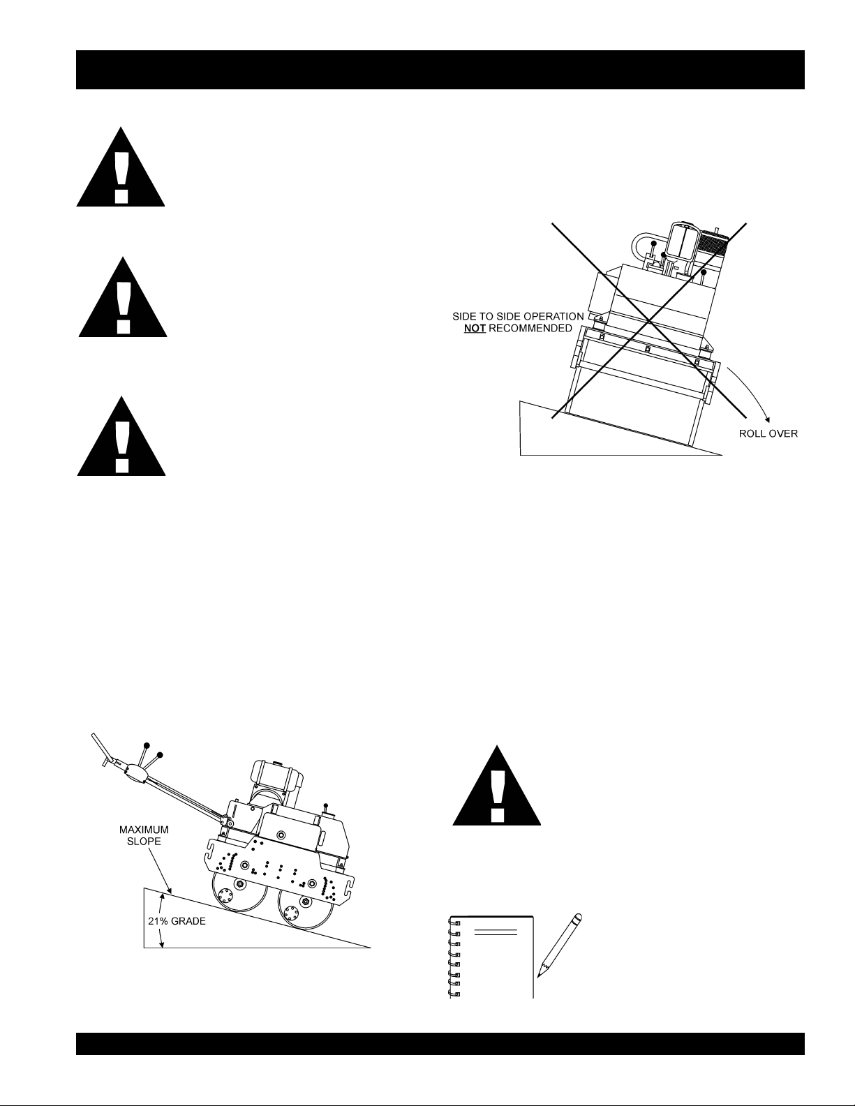
Tipping (Rollovers)
NEVER! operate the roller on side slopes (Figure 5). The
possibility exist that the roller could tip over (roll over), thus
causing bodily harm even death and serious damage to the
equipment.
ONLY! use steel ropes or chains that are
capable of lifting at least 1,940 lbs. (880 kg ).
Figure 5. Recommended Slope
OPERATING ON SLOPES
Special care must be taken when operating the roller on hills or
slopes. There exist the possibility of serious injury to the operator
and severe damage to the roller in the event of a roll over.
ALWAYS operate the roller up and down hills rater than from
side to side. For safe operation hillside slopes should not exceed
12 degree (21 % grade). See Figure 4 below.
In the event the roller does tip over, extreme care must be taken
to prevent damage to the engine. When the roller has been
tipped over, oil from the engine crankcase can flow into the
combustion chamber, which can severely damage the engine
the next time it is started.
IMMEDIATELY after a unit has tipped over upright the unit as
soon as possible to prevent oil from leaking into the combustion
chamber.
CAUTION :
NOTE
Figure 4. Recommended Slope
To prevent damage to the engine after a
rollover, the unit must NOT be started.
NEVER start a unit after a rollover. CONTACT
your nearest authorized Multiquip dealer for
instructions or servicing.
NEVER! operate the roller on
slopes
causing injury to personnel and
severe damage to the equipment
. The roller may tip over
side
MQ-MIKASA MDR-9DYE VIBRATORY ROLLER — PARTS & OPERATION MANUAL — REV. #0 (12/19/03) — PAGE 15
Page 16
MDR-9DYE — VIBRATORY ROLLER COMPONENTS
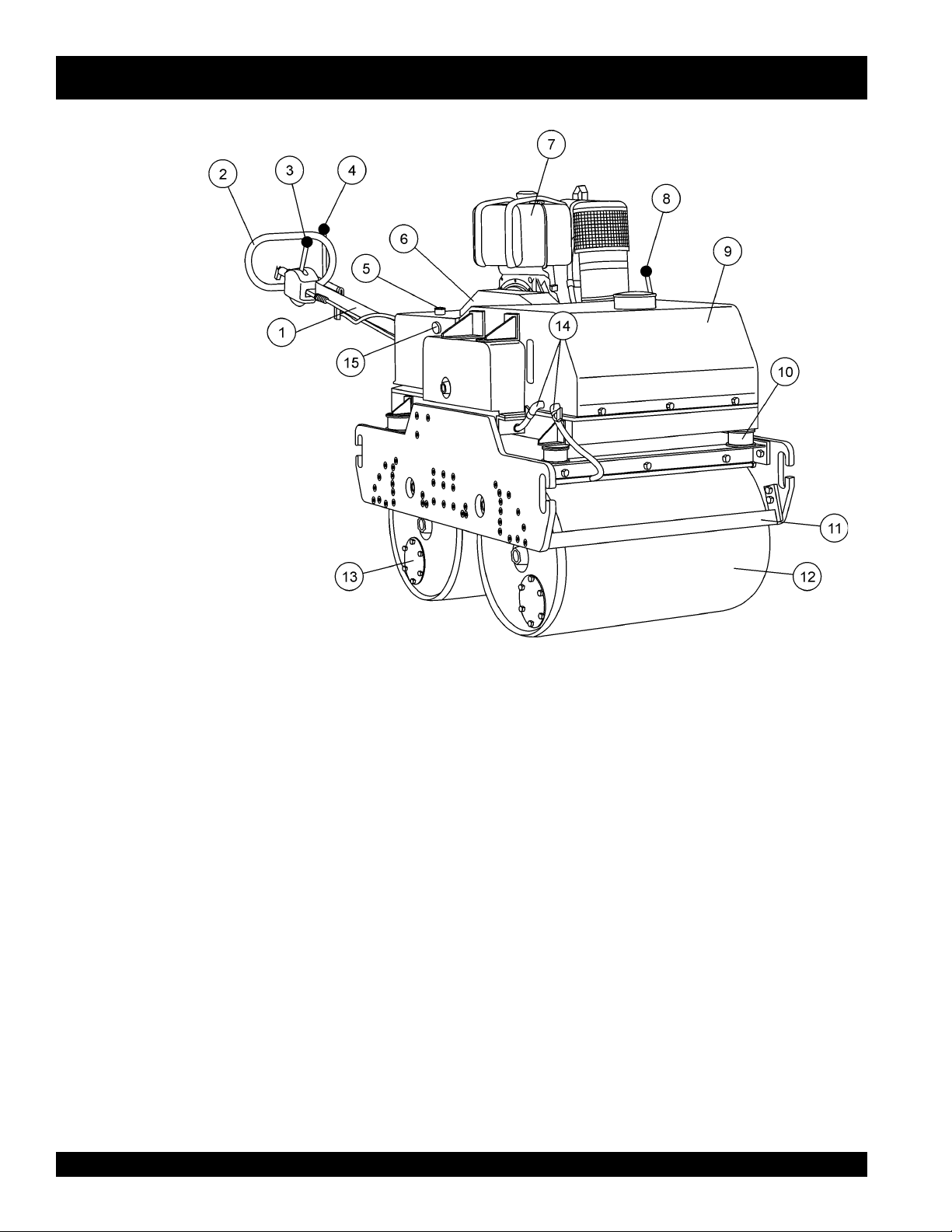
Figure 6. MDR-9DYE Vibratory Roller
Components
Figure 6 illustrates the location of the major components
for the MDR-9D Vibratory Roller. The function of each
component is described below:
1. Handle Bar – When operating the roller, this handle is to
be in the downward position. When the roller is to be
stored
, move the handle bar to the upright position.
2. Hand Grip – When operating the roller, use this hand grip
to maneuver the roller. Also has dead man device, when
pressed or hit while traveling in reverse, causes the travel
lever to return to neutral position to stop the machine.
Push
3. Travel Lever –
in a forward direction,
will move in backwards direction. Placing the lever in the
middle (midway) will cause the roller not to move (neutral).
4. Vibrator Lever – Turns the vibration on and off.
5. Hydraulic Oil Tank/Cap – Stores hydraulic fluid. Open cap
to fill with recommended hydraulic oil (Shell Tellus #46).
6. V-Belt Cover – Remove this cover to gain access to the
v-belts. NEVER run the vibratory roller without the v-belt
cover. If the v-belt cover is not installed, the possibility exist
that your hand may get caught between the v-belt and clutch,
thus causing serious injury and bodily harm.
the lever forward, the roller will move
pull
the lever backwards, the roller
7. Engine – This vibratory roller uses a YANMAR L100EE-
DEVMK2 diesel engine. Refer to the owner’s manual for
engine information and related topics.
8. Vibrator Lever (on the body of machine) – Turns the
vibration on and off.
9. Water Tank – Holds 6 gallons (23 liters) of water for the
sprinkler system.
10. Shock Absorber -
11. Scraper Bar – This bar helps prevent buildup of material
between the drum and the frame.
12. Vibration Rollers – 18-inch diameter steel drums that
provide the compaction force in the compaction and
patching of asphalt-type surfaces.
13. Checking Cover for Chains – Take off the cover to check
and lubricate chains.
14. Water Valves– Turn on the water sprinkling system.
15. Hydraulic Oil Gauge – Indicates the hydraulic oil level.
PAGE 16 — MQ-MIKASA MDR-9DYE VIBRATORY ROLLER — PARTS & OPERATION MANUAL — REV. #0 (12/19/03)
Page 17

MDR-9DYE — YANMAR L100EE-DEVMK2 ENGINE COMPONENTS
Figure 7. YANMAR L100EE-DEVMK2 Engine Components
ENGINE COMPONENTS
Figure 7 illustrates the location of the major engine
components of the Yanmar engine. Each component is
described below:
1. Fuel Filler Cap – Remove this cap to add unleaded
gasoline to the fuel tank. Make sure cap is tighten securely.
DO NOT over fill.
2. Fuel Tank – Diesel engine holds 5.8 quarts of diesel fuel.
3. Air Cleaner – Prevents dirt and other debris from entering
the fuel system. Remove wing-nut on top of air filter
cannister to gain access to filter element.
4. Muffler – Used to reduce noise and emissions.
5. Recoil Starter (pull rope) – Type of engine starting method.
Alternate type would be electric start (ignition key).
6. Recoil Starter – Housing for pull rope and starter.
7. Oil Filler Cap/Dipstick – Remove this cap to add oil to the
oil tank. Use dipstick to check oil level.
8. Oil Drain Plug – Unscrew plug to drain oil from engine
crankcase. Dispose of oil in a safe manner.
9. Decompression Lever – Press down before starting
engine. To prevent damage to the engine, DO NOT use for
any other purpose.
10. Fuel Cock – Controls the flow of diesel fuel to the engine.
Must be in the ON position when starting and running the
engine.
MQ-MIKASA MDR-9DYE VIBRATORY ROLLER — PARTS & OPERATION MANUAL — REV. #0 (12/19/03) — PAGE 17
Page 18
MDR-9DYE — INSPECTION
CAUTION :
Never operate the vibratory
roller in a confined area or
enclosed structure that
does not provide ample
free flow of air.
ALWAYS wear approved eye and hearing
protection before operating the vibratory roller.
BEFORE STARTING
1. Read safety instructions at the beginning
of manual.
2. Familiarize yourself with the operating
and control elements of the machine and
the working environment. This includes obstacles in the
working area, bearing capacity of the ground and the
necessary safety provisions.
3. Check the air filter for dirt and dust. If the air filter is dirty, replace
air filter with a new one as required.
4. Check fastening nuts and bolts for tightness. Loose threads
may cause damage to the machine when vibrating.
3. If the oil level is low, fill to the edge of the oil filler
hole with the recommended oil type (Table 4).
Maximum oil capacity is 1.6 quarts (1.1 liters).
Explosive Fuel
Explosive Fuel
DANGER
CHECKING FUEL
EPYTLIO.4ELBAT
nosaeS erutarepmeT epyTliO
remmuS rehgiHroC°52 03-W01EAS
llaF/gnirpS C°01~C°52 02/03-W01EAS
retniW rewoLroC°0 01-W01EAS
Diesel fuel is highly flammable and can be
dangerous if mishandled. DO NOT smoke while
refueling. DO NOT attempt to refuel the vibra-
hot!
or
tory roller if the engine is
running.
5. Understand the geographical features and regulations of
the job site.
6. Clean the vibratory roller, removing dirt and dust, particularly,
the bottom of the plate, engine cooling air inlet.
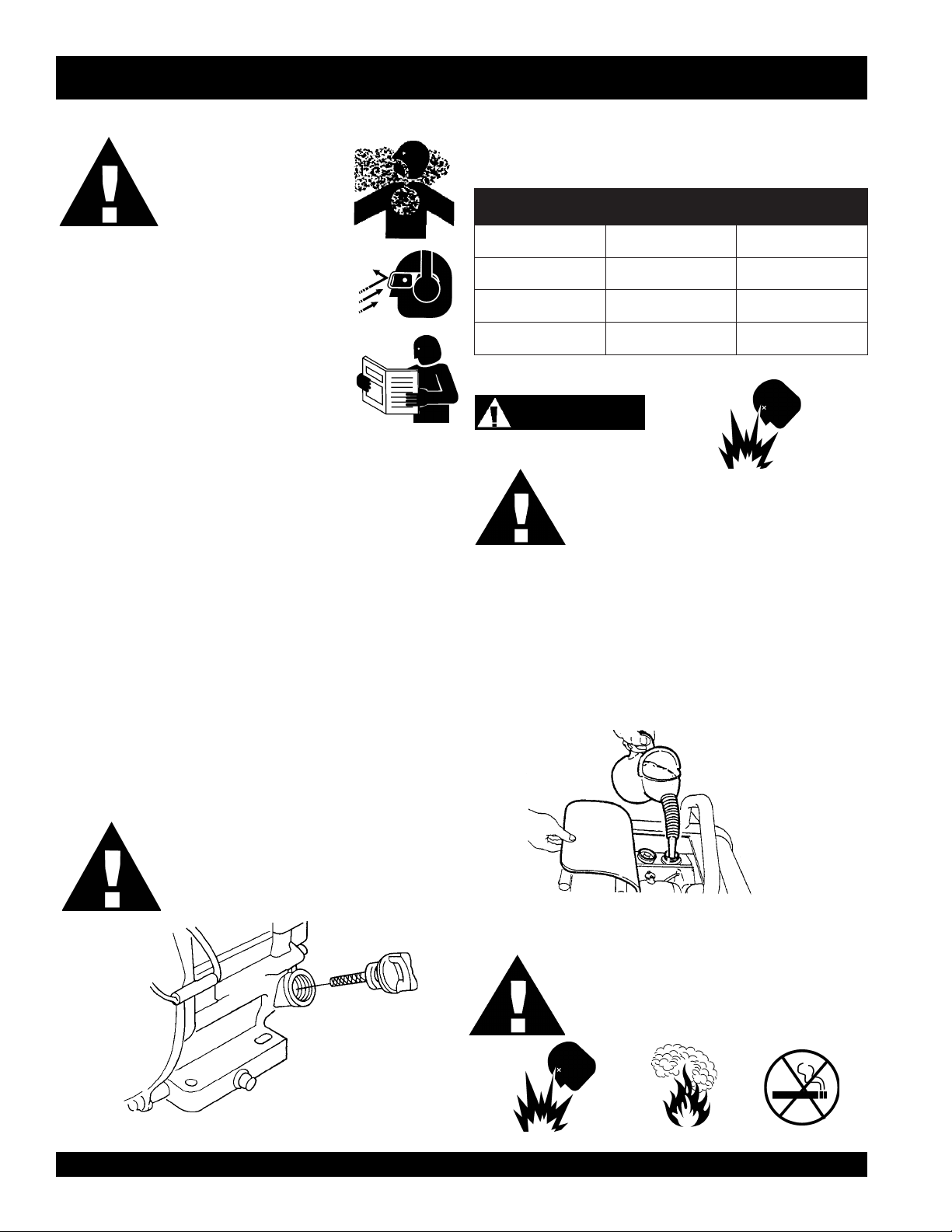
CHECKING ENGINE OIL LEVEL
1. Make sure that the machine is situated in a flat
surface so that level measurements will be accurate.
2. Pull out the dipstick from the oil tank (Figure 8).
1. Remove the fuel cap located on top of fuel tank.
2. Visually inspect to see if fuel level is low. If fuel is low, replenish
with diesel fuel (Figure 9).
3. When refueling, be sure to use a strainer for filtration. DO NOT
top-off fuel. Wipe up any spilled fuel.
CAUTION :
DO NOT overfill oil tank. This could cause oil
leaks and sluggish operation. Clean cap and
surrounding area before opening to prevent dirt
from entering tank.
DANGER
Figure 9. Refueling
Fuel spillage on a hot engine can case a
explosion
spilled fuel completely to prevent fire hazards.
NEVER!
. If fuel spillage occurs, wipe up the
smoke around or near the roller.
fire
or
Figure 8. Oil Dipstick
PAGE 18 — MQ-MIKASA MDR-9DYE VIBRATORY ROLLER — PARTS & OPERATION MANUAL — REV. #0 (12/19/03)
Page 19

MDR-9DYE — INSPECTION
CHECKING HYDRAULIC SYSTEM
1. Check the oil tank level gauge (Figure 10). Oil level
should be at the middle indication of the gauge or
higher. Fill as required
2. Check the surroundings of the oil tank, hydraulic
pump and motor for oil leakage.
Figure 10. Hydraulic System Oil Level Gauge
DANGER
ALWAYS keep hands and fingers away from
pinch points. DO NOT allow anyone to reach in
on dangerous sections of the machine to avoid
any accidents.
CHECKING THE CLUTCH BOX OIL LEVEL
1. Check clutch box for any oil leakage.
2. Remove the level plug and check oil level (Figure 12).
3. Add oil if necessary.
CHECKING THE VIBRATOR OIL LEVEL
1. Remove the red filler plug and the oil level inspection hole
plug from the vibrator case (Figure 13).
2. Fill with oil until oil overflows from inspection hole.
Figure 12. Clutch Box Oil Level Check
CHECKING THE V-BELT
1. Check all bolts and screws and make sure all are
securely tightened.
2. Check V-belt for proper tension. The normal slack
should be approximately 1/8 inch (3 to 5 mm) when
the belts are forcibly depressed between the two
sheaves (Figure 11). Insufficient tension causes
weak vibration and machine damage.
Figure 11. V-Belt Tension
Figure 13. Vibrator Oil Level Check
MQ-MIKASA MDR-9DYE VIBRATORY ROLLER — PARTS & OPERATION MANUAL — REV. #0 (12/19/03) — PAGE 19
Page 20

MDR-9DYE — INSPECTION
CHECKING WATER TANK
1. Check the water tank to see if filled. Add water if necessary.
The water tank has a capacity of approximately 6 gallons
(23 liters) (Figure 14).
Figure 14. Water Tank Check
CAUTION :
Be careful not to confuse the water tank with the
oil tank.
POSITIONING THE HANDLE BAR
1. Release the handle bar release pin (Figure 15) and position
the handle bar to the lowered position before starting
operation.
2. When machine is not in use, release the handle bar release
pin and position the handle bar to the upright position.
Handle Bar
Release Pin
Figure 15. Handle Bar Positioning
INITIAL STARTUP (ENGINE)
CHECKING LEVERS
1. Check travel and vibrator levers to make sure they are
functioning properly (Figure 6).
2. With travel lever placed in reverse, push the deadman
device and verify that the travel lever returns to neutral
position. The travel lever stays in neutral position once the
deadman device is released.
CHECKING SCRAPER BAR
1. Check scraper bar and make sure that they are not clogged
with mud, bent or damaged (Figure 6).
2. Adjust clearance between drums and scrapers as
necessary.
CHECKING BOLTS, NUTS, AND SCREWS
1. Check bolts, nuts, and screws on various parts of the
machine, including the engine, for proper tightness.
Electric Start
1. On the handle bar:
A. Move the
B. Move the
2. Open the fuel cock by turning it clockwise to the
down position (Figure 16).
travel lever
vibrator lever
to the NEUTRAL position.
to the OFF position.
Figure 16. Open Fuel Cock
PAGE 20 — MQ-MIKASA MDR-9DYE VIBRATORY ROLLER — PARTS & OPERATION MANUAL — REV. #0 (12/19/03)
Page 21
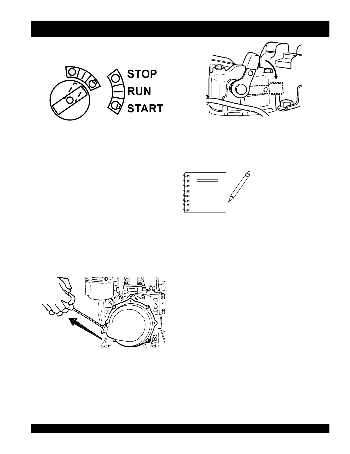
3. Insert the starter key into the key switch and turn it to
the RUN position (Figure 17).
Figure 17. Starter Key
4. Turn the starter key further to the right to the START
position to start the engine.
5. If the engine fails to start, DO NOT continue to rotate
the starter key for more than 5 seconds. Return the
key to the RUN position and wait 20 to 30 seconds
before starting again.
6. After starting the engine, continue to warm up the
engine for about 3 to 10 seconds especially in cold
weather.
Recoil Start
NOTE
MDR-9DYE — OPERATION
Figure 19. Decompression Lever
When starting with a motor
starter, a decompressor is
not normally required.
However, when ambient
temperature or battery
charger level is low, use of
a decompressor will help
make the start-up easier.
1. Open the fuel cock by turning it clockwise to the down
position (Figure 16).
2. Pull the starting handle slowly until you feel some
resistance (Figure 18). Return handle to original
position.
Figure 18. Engine Start Handle
3. Push down the decompression lever (Figure 19).
4. Pull the starting handle hard and fast to start engine.
5. If the engine does not start, repeat steps
2 through 4.
MQ-MIKASA MDR-9DYE VIBRATORY ROLLER — PARTS & OPERATION MANUAL — REV. #0 (12/19/03) — PAGE 21
Page 22
MDR-9DYE — OPERATION
TRAVELING
CAUTION :
Make sure to follow all safety rules referenced in
the safety section of this manual before operating
roller. Keep work area clear of debris and other
objects that could cause damage to the roller or
bodily injury.
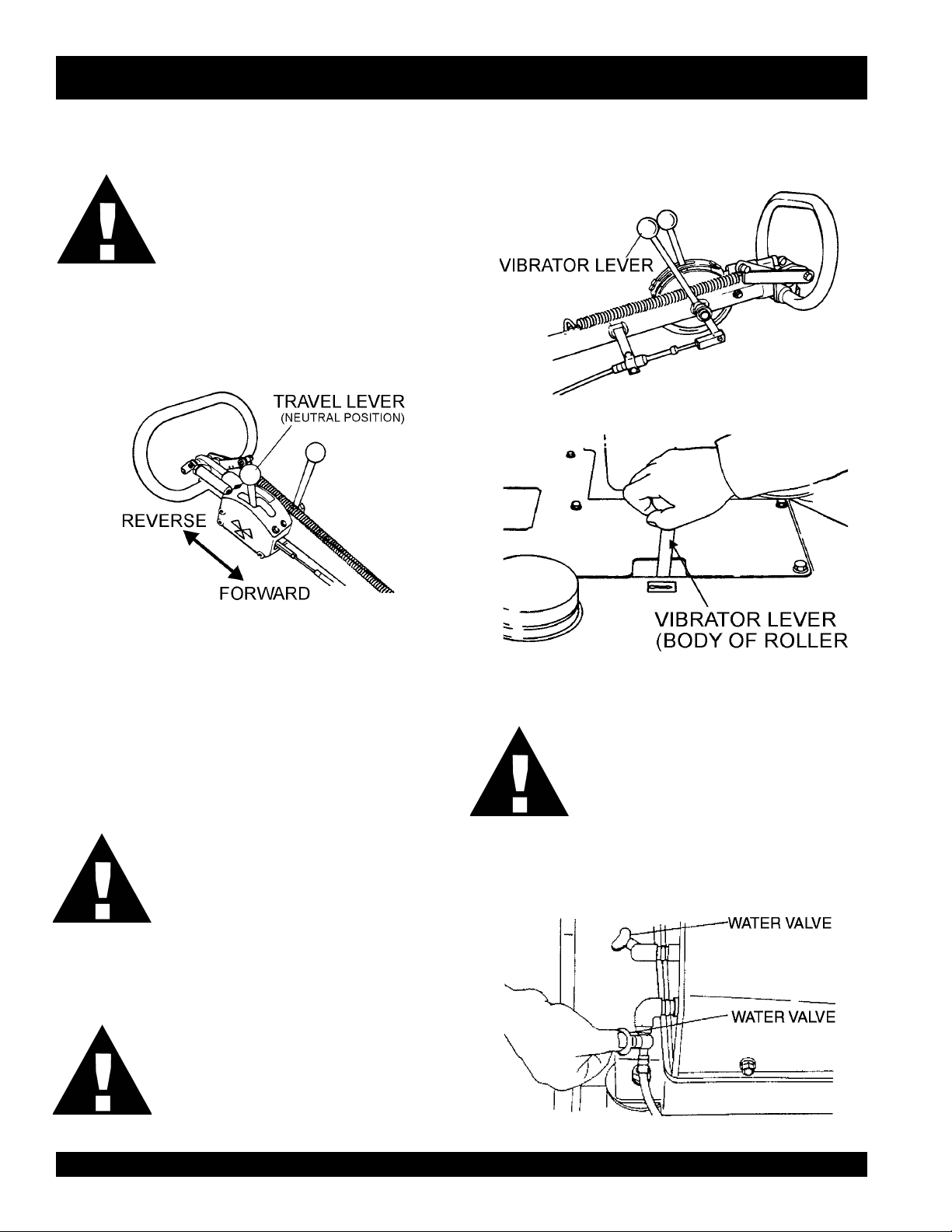
1. To make the roller move in the forward direction push the
travel lever ( Figure 20) forward. This roller has a hydraulic
variable speed transmission. By moving the travel lever
varioys increments, you can vary the speed from 0 to 1.8 mph
(0 to 3 km/hr).
VIBRATING
1. Shift the two vibrator levers (Figures 21 and 22) to the
vibrate position to start vibrations.
Figure 21. Vibrator Lever
Figure 20. Travel Lever
2. To make the roller move in the reverse direction pull the travel
lever ( Figure 20) backwards.
CAUTION :
3. Firmly gasp the roller's hand grip, the roller will begin moving
in the desired position when the direction lever has been
placed in the desired position.
CAUTION :
DO NOT reduce speed during work. When
shifting travel lever from forward to reverse,
be sure to stop the lever at the neutral
position first before moving the lever to the
opposite direction. DO NOT shift the lever
from forward to reverse (or reverse to
forward) in one motion.
WATERING
1. To operate water sprinkling system, turn on the front and
rear water valves on the side of the roller. (Figure 23).
CAUTION :
After test travel, shut down engine and
check for any problems including oil
leakage. If any trouble is found, correct the
problem before attempting to operate the
roller again.
Figure 22. Vibrator Lever (Body)
Using vibration with clutch slipping causes
the clutch to burn. Also, vibration should
NOT be used over completely compacted
area, paved road surface, or with stationary
roller.
Figure 23. Water Valves
PAGE 22 — MQ-MIKASA MDR-9DYE VIBRATORY ROLLER — PARTS & OPERATION MANUAL — REV. #0 (12/19/03)
Page 23

MDR-9DYE — OPERATION
STOPPING
1. Place the vibrator and travel levers to the neutral position.
2. Slow down the engine and allow to cool for at least 2
minutes. In an electric start, return the key switch to
the STOP position as soon as the engine stops.
CAUTION :
Neglecting to return the key switch to the
STOP position will cause the battery to
discharge, making start-up impossible the
LIFTING
1. Use a crane or lift to load and unload the machine. A
skilled crane operator is required to perform the job.
2. When lifting the machine, check for any damaged or
loose bolts, lifting hooks, and shock mounts.
3. Check any damaged or loose bolts in the guard frame to
avoid machine sliding off.
4. Make sure that the machine is shut off before machine is
lifted.
5. Use reliable cable for lifting.
next time.
6. Always lift the machine vertically and keep the
3. After the engine stops, close the fuel cock.
4. The hydraulic brake is automatically engaged when the
travel lever is in neutral position. When parked on a slope
with the engine turned off, place a block against the
roller drum to prevent the roller from moving.
UNLOADING
1. If you need to move the roller by pushing it manually
once engine is stopped, push in the upper and lower
knobs of the transmission check valve. This will
cause the hydraulic break to disengage and allow
the roller to be moved without causing damage
(Figure 24).
machine away from workers and animals.
7. Do not lift the machine higher than the required
height.
TRANSPORTING
1. Always make sure that the machine is shut off while
being transported.
2. Check that the fuel cap is properly closed and
tightened.
3. When traveling long distances or on rugged terrain,
drain the fuel of the machine before transporting.
4. Tie down the machine securely on the
transportation so that it will not move or topple over.
Figure 24. Disengaging Hydraulic Brake
2. After moving, reset upper and lower knobs.
CAUTION :
NEVER tow roller with any type of vehicle.
Doing so will damage the hydraulic system.
NEVER perform unloading procedure on a
slope. This may cause roller to roll down if
parking brake or blocking is deficient.
MQ-MIKASA MDR-9DYE VIBRATORY ROLLER — PARTS & OPERATION MANUAL — REV. #0 (12/19/03) — PAGE 23
Page 24
MDR-9DYE — MAINTENANCE
CAUTION:
Inspection and other services should
be carried out on hard and level ground with
the engine shutdown.
INSPECTION AND MAINTENANCE SERVICE TABLES
1. To make sure your plate vibratory roller is always in good
working condition before using, carry out the maintenance
inspection in accordance with Tables 5 through 7.
EYD9-RDM.5ELBATNOITCEPSNIENIHCAM
METI
gnissiMroesooL
swercS
straPdegamaD
gnillortnoCfonoitcnuF
traPmetsyS
FOSRUOH
NOITAREPO
sruoh8yrevE
)yadyreve(
sruoh8yrevE
)yadyreve(
sruoh8yrevE
)yadyreve(
always
SKRAMER
CAUTION:
Fuel piping and connections should be
replaced every 2 years.
METINOITAREPOFOSRUOH
kaeLleuFroliO)yadyreve(sruoh8yrevE
sdaerhT
tnemhsinelpeR
gninaelCretliFriAsruoh001yrevE
EYD9-RDM.6ELBATKCEHCENIGNE
gninetsaFfossenthgiT
dnakcehCliOenignE
)level
tnemecalpeRliOenignE
sruoh001
)yadyreve(sruoh8yrevE
)yadyreve(sruoh8yrevE
mumixamdeificepsothsinelpeR(
ot05yrevenehtsruoh52tsrifretfA
noisneTniahC
tnemtsujdA
tnemecalpeR
liOciluardyH
tnemecalpeR
CAUTION:CAUTION:
CAUTION:
CAUTION:CAUTION:
sruoh05yrevE62egapeeS
52retfayllaitinI
yreveneht,sruoh
2(sruoh052
retliFliOciluardyH
kcehCliOciluardyH
kcehChctulCnoitarbiVyrassecensA72egapeeS
yreve,)shtnom
4(sruoh005
yreve,)shtnom
sruoh000,1
.retfaereht
ot4yreve,yllaitinI
enoretfA.sruoh5
.yadaeciwt,keew
,skeew2retfA
.yadaecno
ot000,1yrevE
sruoh005,1
82egapeeS
72egapeeS
72egapeeS
These inspection intervals are for operation
under normal conditions. Adjust your inspection
intervals based on the number hours vibratory
roller is in use, and particular working conditions.
DAILY SERVICE
z
Check for leakage of fuel or oil.
z
Check for loose screws including tightness. See Table 6
below (tightening torque ), for retightening:
T4 07 051 003 005 057 001,1 004,1 000,2
T8-6 001 052 005 008 003,1 000,2 007,2 008,3
T11 051 004 008 002,1 000,2 009,2 002,4 006,5
* 001
z
Remove soil and clean the bottom of roller.
z
Check the levers, cables and linkage.
z
Check engine oil.
mm6 mm8 mm01 mm21 mm41 mm61 mm81 mm02
lairetaM
~003
~056
053
007
)munimulafositrap-retnuocesacnI(*
)dednahthgirllaeraenihcamsihthtiwesunisdaerhT(
.kcehcenignenosliatedroflaunamenigneetarapeseeS
)mc/gk.ni(EUQROTGNINETHGIT.7ELBATRETEMAID
.wercsdna,tlobhcaenodekramsilairetamfoytilauqdnalairetaM
PAGE 24 — MQ-MIKASA MDR-9DYE VIBRATORY ROLLER — PARTS & OPERATION MANUAL — REV. #0 (12/19/03)
Page 25
ENGINE OIL REPLACEMENT
1. Replace engine oil in the first 25 hours of operation and
every 50 to 100 hours afterwards.
2. Oil may be drained more easily when it is warm after
operation (For more details, see separate engine Owner's
Manual).
AIR FILTER
1. The air filter element should be cleaned because a clogged
air cleaner can cause poor engine starting, lack of power
and shorten engine life substantially.
CAUTION:
Figure 25. Engine Air Filter and Element
MDR-9DYE — MAINTENANCE
Figure 27. Chain Tightener
NEVER attempt to check the V-belt with the engine
running. Severe injury can occur if your hand gets
caught between the V-belt and the clutch (Figure
28). Always use safety gloves.
CLUTCH
PULLEY
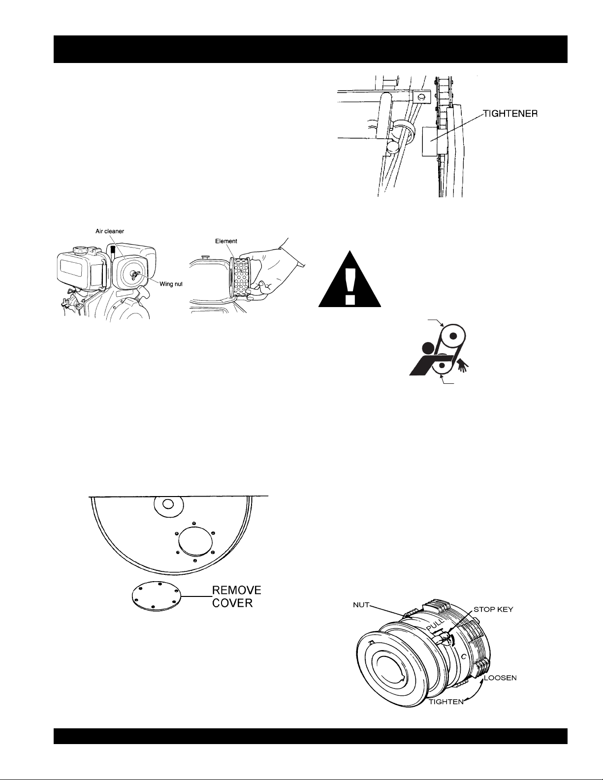
2. To clean or replace air filter loosen the wing nut on the air
filter housing (Figure 25) remove the cover and take out air
filter cartridge. If only cleaning of the air filter is desired blow
through the air filter cartridge from the inside, moving a jet of
dry compressed air up and down until all dust is removed.
CHECKING THE CHAINS
1. Take off the checking cover on roller and coat grease on the
chain if necessary (Figure 26. The chain should be lightly
lubricated with motor oil.
Figure 26. Chain Cover
VIBRATOR
PULLEY
Figure 28. V-Belt Hazard
VIBRATION CLUTCH ADJUSTMENT
1. Remove the protective cover from the clutch by removing
the 4 allen screws.
2. Pull out the stop key and turn to the release position (Figure
29).
3. Viewing the clutch from the shifter-pulley side: if the clutch
nut is turned to the right, the clearance between the adjusting
and pressure plate decreases as the amount of torque
increases. Normal adjustment is from 1 to 2 notches.
4. Make sure that the shifting lever is not too stiff. Lever should
engage with moderate pressure.
5. After adjustment, return the stop key to the locked position.
2. Check the chain tension and if loose, adjust the chain tension
with the tightener (Figure 27). Chain tension should be
adjusted every 50 hours of operation.
Figure 29. Clutch Adjustment
MQ-MIKASA MDR-9DYE VIBRATORY ROLLER — PARTS & OPERATION MANUAL — REV. #0 (12/19/03) — PAGE 25
Page 26

MDR-9DYE — MAINTENANCE
HYDRAULIC OIL CHECK
1. Check for any oil leakage from the hoses and joints daily.
2. Check hydraulic oil level every 4 to 5 hours after starting
operation.
3. After one week of operation, check hydraulic level twice a
day .
4. After two weeks of operation, check hydraulic level once a
day .
5. Replace hydraulic oil after first 200 hours and in every 1,000
hours of operation.
HYDRAULIC OIL FILTER CHECK
1. The hydraulic oil filter should be replaced after first 25 hours
of operation.
2. After first replacement, it should be replaced after 250 hours
operation (2 months), every 500 hours of operation (4
months), and every 1,000 hours of operation thereafter.
3. When the suction resistance exceeds 254 mmHg (oil
temperature in operation is 140 degrees F), replace filter.
4. To remove the oil filter, wind a cloth around the filter to prevent
slipping (Figure 31).
5. Tie a rope securely around the filter (Figure 31).
CAUTION:
Make sure hydraulic oil is at a normal safe
operating level. DO NOT over fill.
REPLACING HYDRAULIC OIL
1. Change the hydraulic oil every 1,000 to 1,500 hours of
operation. Change the hydraulic oil more often in high
ambient temperature operation.
2. Remove the drain plug and hose tank and drain the hydraulic
oil.
3. Reinstall the drain plug to the oil tank.
4. Open the tank cap (Figure 30) and fill tank with hydraulic oil.
(Capacity: About 4.5 gallons). Use
equivalent.
Figure 30. Hydraulic Oil Change
5. After filling tank, tighten the tank cap firmly with a wrench.
Shell Tellus Oil #46
or
6. Forcibly pull the rope to remove the filter (Figure 32).
7. Immediately replace with new filter, screwing it on by hand
to avoid hydraulic oil leak.
CAUTION:
Make sure that dust , water, and other foreign
objects do not enter tank. It is recommended to
filter the oil through a cloth.
Figure 31. Cloth and Rope Around Filter
Figure 32. Filter Removal
NOTE
Use only genuine Mikasa
replacement oil filters (10
micron filter paper. Do not use
automobile-type oil filters.
PAGE 26 — MQ-MIKASA MDR-9DYE VIBRATORY ROLLER — PARTS & OPERATION MANUAL — REV. #0 (12/19/03)
Page 27
HYDRAULIC AIR EXTRACTION
1. After filling hydraulic oil tank with oil, loosen the oil hose
joint and check that oil is enough to reach the oil suction
and outlet ports in the hydraulic transmission. Tighten the
hose joint securely after checking.
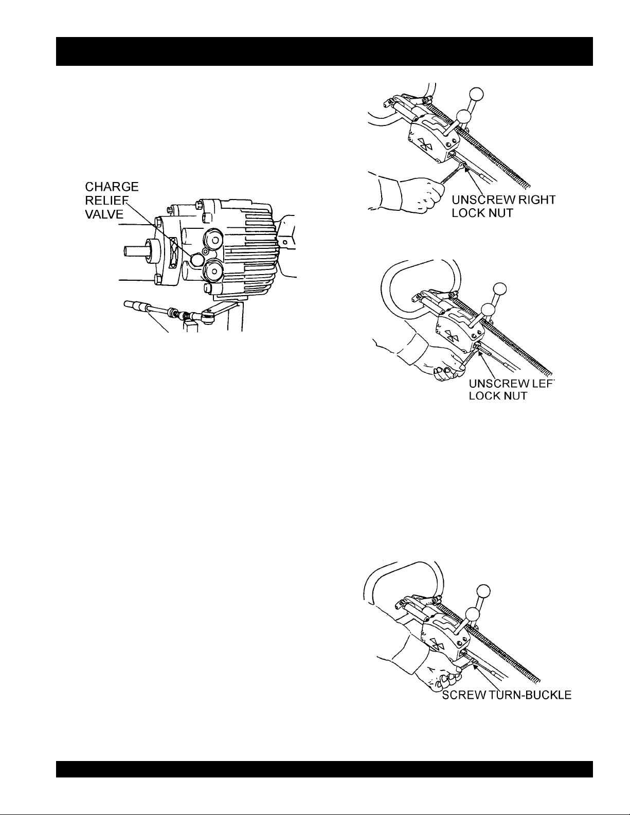
2. Loosen the charge relief valve located on the front side of
the hydraulic transmission (Figure 33).
Figure 33. Loosening Charge Relief Valve
MDR-9DYE—MAINTENANCE
Figure 34. Unscrewing Right Lock Nut
3. Check that oil flows out from the valve hole.
4. Replace the charge relief valve tightly.
5. With the travel and vibrator levers in neutral position, start
the engine and idle at low speed for 3 to 5 minutes.
6. Check the forward and reverse rotation of the output shaft
by moving the travel lever slowly to its forward and reverse
positions.
7. Check the oil level gauge and make sure that there are no
air bubbles mixed in the oil. After checking, operate the roller
slowly at first then at full speed.
8. When oil level in the tank is low, replenish oil up to the
specified level, and screw the cap securely with a wrench.
9. If bubbles remain in the oil or foam is found, air is being
sucked through the suction side and should be checked.
NEUTRAL POSITION ADJUSTMENT
Once the travel lever has been set to neutral position with the
engine running, the hydraulic brake is operating and the roller
should not move. If the roller inches forward or backwards with
the lever in the neutral position, turn-buckle of the cable should
be adjusted as follows:
3. If the machine moves forward, screw the turn-buckle
clockwise. If the machine moves backwards, screw the turnbuckle counterclockwise (Figure 36).
4. Screw back the lock nuts on the turn-buckle.
5. Start the engine and make sure that the roller does not inch
forward or backward at the neutral position of the travel
lever.
Figure 35. Unscrewing Left Lock Nut
1. Stop the engine and set the travel lever in the neutral
position.
2. Unscrew the two lock nuts on the sides of the cable (Figures
34 and 35).
MQ-MIKASA MDR-9DYE VIBRATORY ROLLER — PARTS & OPERATION MANUAL — REV. #0 (12/19/03) — PAGE 27
Figure 36. Adjusting the Turn-Buckle
Page 28

MDR-9DYE—MAINTENANCE
If the neutral position of the travel lever and the neutral point of
transmission do not match after adjustment is repeated, align as
follows:
1. Loosen the hex socket head bolt M10 used for mounting the
control lever on the underside of the transmission (Figure
37).
2. For forward movement, move the control lever slightly to the
left.
3. for backwards movement, move the control lever slightly to
the right.
Figure 37. Unscrewing Left Lock Nut
BATTERY MAINTENANCE
DANGER :
Lead-acid battery contains
sulfuric acid, which may damage
eyes or skin on contact.
zz
z
DO NOT close the exhaust outlet of battery. The gas pressure
zz
building up in the battery may cause explosion.
zz
z
Before using a battery charger, read and understand the
zz
charger instruction manual thoroughly.
zz
z
Charge the battery in a non-spark, well-ventilated area. Avoid
zz
fire from cigarette sparks or matches.
1. If a battery has not been used for some time, reduce
the charge level initially to protect each plate inside
the battery.
2. Check the battery terminals periodically to ensure
that they are in good condition.
3. Use wire brush or sand paper to clean the battery
terminals.
4. Check battery for cracks or any other damage. If white
pattern appears inside the battery or paste has
accumulated at the bottom, replace the battery.
5. Measure the specific gravity of electrolyte:
zz
z
zz
zz
z
zz
6. If the machine will not be in operation for a long
period of time, charge the battery sufficiently, tighten
all caps, correctly, store in cool dry place and check
the battery charge level every month to maintain the
performance of the battery.
BATTERY CABLE CONNECTION
1. When removing cable, disconnect the ground side
(normally negative) first (Figure 38).
completely charged: 1.270 - 1.290
needs charging: 1.260 or lower
2. When installing cable connect the ground side (normally
negative) last.
FOR YOUR SAFETY:
zz
z
ALWAYS wear a face shield to avoid acid getting into the
zz
eyes. If acid gets in contact with eyes, flush immediately with
clean water and get medical advice.
zz
z
Wear rubber gloves and protective clothes to keep acid off
zz
skin. If acid gets in contact with skin, wash off immediately
with clean water.
zz
z
Use a flashlight to check battery electrolyte level. ALWAYS
zz
check the engine is stopped.
zz
z
DO NOT charge battery or jump-start engine when the
zz
battery is frozen. Warm the battery to 15 degrees F or battery
may explode.
zz
z
Replace the battery with the same or similar capacity battery
zz
or battery may explode.
PAGE 28 — MQ-MIKASA MDR-9DYE VIBRATORY ROLLER — PARTS & OPERATION MANUAL — REV. #0 (12/19/03)
Negative
Terminal
Positive
Terminal
Figure 38. Battery Connection
Page 29

MDR-9DYE — ENGINE TROUBLESHOOTING
Practically all breakdowns can be prevented by proper handling and maintenance inspections, but in the event of a breakdown,
please take a remedial action following the diagnosis based on the Engine and Roller Troubleshooting (Tables 8 and 9) information
shown below and on the proceeding page. If the problem cannot be remedied, please leave the unit just as it is and consult our
company's business office or service plant.
GNITOOHSELBUORTENIGNE.8ELBAT
MOTPMYSMELBORPELBISSOPNOITULOS
?noitisop"POTS"nisirevellortnocdeepS .noitisop"TRATS"otrevellortnocdeepsteS
?pmupnoitcejnignihcaerleufoN .metsysleuferitnekcehC.leufddA
?pmupleufevitcefeD.pmupleufecalpeR
?deggolcretlifleuF .knatnaelcdnaretlifleufecalpeR
sitratsrotratstonlliwenignE
ebnacenignehguohtla,deyaled
.revodenrut
lliwenigneserutarepmetwoltA
.tratston
sanoosspotstubserifenignE
.ffodehctiwssiretrats
gnirudflestiybspotsenignE
.noitarepolamron
?enilylppusleufytluaF .enilleufriaperroecalpeR
?wolootnoisserpmoC
?yltcerrocgnikrowtonrotcejnileuF
?wolooterusserpliO .erusserplioenignekcehC
?dedeecxetimilerutarepmetgnitratswoL
otecnatsiseretauqedanisahsetarapesleuF
?serutarepmetwol
?kcihtootlioenignE
?noitisopPOTSnirevelelttorhT .noitisopNURotrevelelttorhtnoitisopeR
?dekcolbretlifleuF.retlifleufecalpeR
?dekcolbylppusleuF .metsysleuferitneehtkcehC
?ytpmeknatleuF.leufddA
?dekcolbretlifleuF.retlifleufecalpeR
rotsujdA.sevlavdnarednilyc,notsipkcehC
.launamriaperenignerepriaper
htiwecnadroccanirotcejniecalperroriapeR
.launamriaperenigne
dnasnoitcurtsnignitratsdlochtiwylpmoC
.ytisocsivlioreporp
segremeleuf)dibrutton(raelcrehtehwkcehC
.)pmupnoitcejnimorfhcated(enilleufehtmorf
ehtpumraw,detarapesrodibrutsileufehtfI
ylppusleufetelpmocehtniardroenigne
.leufleseidedargretniwhtiwleufeR.metsys
liofoepyttcerrochtiwesacknarcenignellifeR
.tnemnorivneretniwrof
?ytpmeknatleuF.retlifleufecalpeR
?deggolcretlifleuF.retlifleufecalpeR
dnatuptuo,rewopenignewoL
.deeps
?noitisopdetceles
?llufootlevellioenignE.levellioenignetcerroC
?dekcolbretlifriA .retlifriaecalperronaelC
dnatuptuorewopenignewoL
.ekomstsuahxekcalb,deepswol
?rotcejnitanoitcnuflaM.launamenigneeeS
?etauqedanisignitnevknatleuF .detnevyletauqedasiknattahterusnE
niniamertonseodrevellortnocdeepS
?secnaraelcevlavtcerrocnI .noitacificepsenignerepsevlavtsujdA
.noitcaevitcerrocroflaunamenigneeeS
MQ-MIKASA MDR-9DYE VIBRATORY ROLLER — PARTS & OPERATION MANUAL — REV. #0 (12/19/03) — PAGE 29
Page 30

MDR-9DYE — ENGINE TROUBLESHOOTING
Practically all breakdowns can be prevented by proper handling and maintenance inspections, but in the event of a breakdown,
please take a remedial action following the diagnosis based on the Engine Troubleshooting (Table 8) information shown below and
on the proceeding page. If the problem cannot be remedied, please leave the unit just as it is and consult our company's business
office or service plant.
)DEUNITNOC(GNITOOHSELBUORTENIGNE.8ELBAT
MOTPMYSMELBORPELBISSOPNOITULOS
?ytpmeknatleuF.retlifleufecalpeR
?deggolcretlifleuF.retlifleufecalpeR
dnatuptuo,rewopenignewoL
.deeps
?noitisop
?llufootlevellioenignE ?levellioenignetcerroC
?dekcolbretlifriA .retlifriaecalperronaelC
dnatuptuorewopenignewoL
.ekomstsuahxekcalb,deepswol
?rotcejnitanoitcnuflaM.launamenigneeeS
?etauqedanisignitnevknatleuF .detnevyletauqedasiknattahterusnE
detcelesniniamertonseodrevellortnocdeepS
?secnaraelcevlavtcerrocnI .noitacificepsenignerepsevlavtsujdA
.noitcaevitcerrocroflaunamenigneeeS
PAGE 30 — MQ-MIKASA MDR-9DYE VIBRATORY ROLLER — PARTS & OPERATION MANUAL — REV. #0 (12/19/03)
Page 31

MDR-9DYE — ROLLER TROUBLESHOOTING
Practically all breakdowns can be prevented by proper handling and maintenance inspections, but in the event of a breakdown,
please take a remedial action following the diagnosis based on the Roller Troubleshooting (Table 9) information shown below and
on the proceeding page. If the problem cannot be remedied, please leave the unit just as it is and consult our company's business
office or service plant.
GNITOOHSELBUORTRELLOR.9ELBAT
MOTPMYSMELBORPELBISSOPNOITULOS
?hctulclagufirtnecevitcefeD .hctulcecalperroriapeR
?egnalfdnagnilpuocrebburdegamaD .egnalfdnagnilpuocrebburecalpeR
?knildnaelbaclevartevitcefeD .knildnaelbaclevartecalperroriapeR
?reparcsnidumhcumootroreparcsdegamaD .reparcsriaperroecalpeR
rolevarttonseodtinU
.htoomstonsilevart
?noitatormurddaB .murdecalperroriapeR
roetarbivtonseodtinU
.noitarbivkaewsah
?retlifliodeggolcrodegamaD.retlifecalpeR
?epipciluardyhgnikaelrodegamaD .strapecalperroriapeR
?liodetanimatnocrolevelliowoL .lioecalperrohsinelpeR
?noissimsnartciluardyhgnikaelrodegamaD .pmupciluardyhecalperroriapeR
?noissimsnartciluardyhgnikaelrodegamaD .rotomciluardyhecalperroriapeR
?gniraebdnaraegmurddegamaD.strapriapeR
?hctulclagufirtnecevitcefeD .hctulcecalperroriapeR
?tleb-VgnippilsrodegamaD .noisnettsujdarotleb-VecalpeR
?egaknildnaelbacnoitarbivdegamaD
?hctulcnoitarbivdegamaD .hctulcecalperrotsujdA
?tleb-VyelluprotarbivhctulcevitcefeD.tleb-VecalpeR
?dnahhtiwylhtoomsnruttonseodrotarbiV
dnaelbacnoitarbivriaperroecalpeR
.egaknil
liofikcehC.rotarbivriaperdnakcehC
.hgihylevissecxetonsilevel
MQ-MIKASA MDR-9DYE VIBRATORY ROLLER — PARTS & OPERATION MANUAL — REV. #0 (12/19/03) — PAGE 31
Page 32

EXPLANATION OF CODE IN REMARKS COLUMN
How to read the marks and remarks used in this parts
book.
Items Found In the “Remarks” Column
Serial Numbers-Where indicated, this indicates a serial number
range (inclusive) where a particular part is used.
Model Number-Where indicated, this shows that the
corresponding part is utilized only with this specific model number
or model number variant.
Items Found In the “Items Number” Column
All parts with same symbol in the number column,
<, belong to the same assembly or kit
If more than one of the same
NOTE
reference number is listed, the
last one listed indicates newest
(or latest) part available.
, #, +, %, or
*
NOTE
The contents of this parts
catalog are subject to change
without notice.
PAGE 32 — MQ-MIKASA MDR-9DYE VIBRATORY ROLLER — PARTS & OPERATION MANUAL — REV. #0 (12/19/03)
Page 33

MQ MIKASA MDR-9DYE VIBRATORY WALK-BEHIND
ROLLER W/YANMAR L100EE-DEVMK2 DIESEL ENGINE
1 to 3 Units
Qty. P/N Description
3 .......... 501010440 ........... OIL FILTER, TRANSMISSION
1 .......... 075080061 ........... CHAIN, DRIVE
6 .......... EM505834 ............ V-BELT
3 .......... 502303040 ........... THROTTLE WIRE
6 .......... 11465012590 ....... ELEMENT, AIR CLEANER
1 .......... 11465076631 ....... ROPE, STARTER
3 .......... 11425055100 ....... FILTER, FUEL SCREEN
6 .......... 11425055121 ....... FILTER, FUEL OIL
3 .......... 11425035110 ....... STRAINER, LUBE OIL ASSY.
3 .......... 10610077630 ....... KEY, IGNITION
SUGGESTED SPARE PARTS
MQ-MIKASA MDR-9DYE VIBRATORY ROLLER — PARTS & OPERATION MANUAL — REV. #0 (12/19/03) — PAGE 33
Page 34

DECAL PLACEMENT
MDR-9DYE — DECAL PLACEMENT
PAGE 34 — MQ-MIKASA MDR-9DYE VIBRATORY ROLLER — PARTS & OPERATION MANUAL — REV. #0 (12/19/03)
Page 35

MDR-9DYE — DECAL PLACEMENT
DECAL PLACEMENT
NO. PART NO. PART NAME QTY. REMARKS
1 920200591 PLATE, CAUTION 1
2 920200630 PLATE, SERIAL NO. 1
3 920201590 DECAL, MQ MARK 98X70 1
4 920101510 DECAL, MIKASA MARK 440MM 1
5 920203290 DECAL, CAUTION 1
6 920200450 DECAL, OIL FILTER 1
7 920101290 DECAL, VIBRATION 2
8 920201100 DECAL, CLUTCH LEVER 2
9 920200320 DECAL, WATER TANK 1
10 920200440 DECAL, PROHIBIT TOW 1
11 920200470 DECAL, OIL TANK 1
12 920101480 DECAL, OIL LEVEL 1
13 920101280 DECAL, FORWARD & REVERSE 1
14 920101200 DECAL, GREASE 1
MQ-MIKASA MDR-9DYE VIBRATORY ROLLER — PARTS & OPERATION MANUAL — REV. #0 (12/19/03) — PAGE 35
Page 36

BODY ASSY.
MDR-9DYE — BODY ASSY.
PAGE 36 — MQ-MIKASA MDR-9DYE VIBRATORY ROLLER — PARTS & OPERATION MANUAL — REV. #0 (12/19/03)
Page 37

MDR-9DYE — BODY ASSY.
BODY ASSY.
NO. PART NO. PART NAME QTY. REMARKS
1 502101270 BASE 1
2 502100720 SIDE PLATE, RIGHT 1
3 502100710 SIDE PLATE, LEFT 1
4 502200960 RUBBER PLATE 2
5 001211430 BOLT 14X30 H 8
6 030214350 LOCK WASHER M14 8
8 930407021 SHOCK ABSORBER MED 4
9 020312100 NUT M12 8
10 030212300 LOCK WASHER M12 8
42 502201150 SPRINKLING PIPE, FRONT 1
43 502201160 SPRINKLING PIPE, REAR 1
44 502402930 VINYL PIPE 10X13X280 1
45 502402940 VINYL PIPE 10X13X950 1
46 001221025 BOLT 10X25 T 6
48 030210250 LOCK WASHER M10 6
49 501010150 CAP 1/4 4
51 502302511 SCRAPER, END 2
52 001221030 BOLT 10X30 T 8
53 030210250 LOCK WASHER M10 8
54 502424050 SCRAPER/CENTER 2
55 001220825 BOLT 8X25 T 6
56 030208200 LOCK WASHER M8 6
57 952401560 WASHER 8.5X20X3 6
58 031110160 FLAT WASHER M10 8
59 502200990 BASE, SCRAPER 1
60 001521225 SOCKET HEAD BOLT 12X25 T 18
68 502403940 CHAIN COVER 2
69 001521020 SOCKET HEAD BOLT 10X20 T 4
82 020310080 NUT M10 4
83 030210250 LOCK WASHER M10 4
MQ-MIKASA MDR-9DYE VIBRATORY ROLLER — PARTS & OPERATION MANUAL — REV. #0 (12/19/03) — PAGE 37
Page 38

FRONT COVER ASSY.
MDR-9DYE — FRONT COVER ASSY.
PAGE 38 — MQ-MIKASA MDR-9DYE VIBRATORY ROLLER — PARTS & OPERATION MANUAL — REV. #0 (12/19/03)
Page 39

MDR-9DYE — FRONT COVER ASSY.
FRONT COVER ASSY.
NO. PART NO. PART NAME QTY. REMARKS
13 031110160 FLAT WASHER M10 4
14 502103800 FRONT COVER 1
16 001220820 BOLT 8X20 T 4
17 030208200 LOCK WASHER M8 7
18 952401560 WASHER 8.5X20X3 7
20 502302490 CHECK COVER 1
21 001220815 BOLT 8X15 T 4
22 030208200 LOCK WASHER M8 4
23 031108160 FLAT WASHER M8 4
24 502302500 SUPPORT/COVER 1
25 001221020 BOLT 10X20 T 1
26 030210250 LOCK WASHER M10 1
27 021110160 FLAT WASHER M10 1
28 001220825 BOLT 8X25 T 3
31 502215470 BELT COVER (GX340) 1
32 001221020 BOLT 10X20 T 2
33 030210250 LOCK WASHER M10 2
34 031110160 FLAT WASHER M10 2
35 001221015 BOLT 10X15 T 2
36 030210250 LOCK WASHER M10 2
37 031110160 FLAT WASHER M10 2
38 502010650 ELBOW 90 DEG. 1/4 2
39 407310670 TANK CAP D108-120, RUBBER 1
41 954403241 COCK PT 1/4, BH-1211 (AL) 2
MQ-MIKASA MDR-9DYE VIBRATORY ROLLER — PARTS & OPERATION MANUAL — REV. #0 (12/19/03) — PAGE 39
Page 40

FRONT COVER ASSY.
MDR-9DYE — FRONT COVER ASSY. (CONTINUED)
PAGE 40 — MQ-MIKASA MDR-9DYE VIBRATORY ROLLER — PARTS & OPERATION MANUAL — REV. #0 (12/19/03)
Page 41

MDR-9DYE — FRONT COVER ASSY. (CONTINUED)
FRONT COVER ASSY.
NO. PART NO. PART NAME QTY. REMARKS
65 001801050 BOLT 10X50 WHOLE THREAD 1
66 020310080 NUT M10
81 001211030 BOLT 10X30 H 4
82 020310080 NUT M10 4
83 030210250 LOCK WASHER M10 4
88 920200591 PLATE, CAUTION 1
89 920200630 PLATE, SERIAL NO. 1
90 920201590 DECAL, MQ MARK 98X70 1
91 920101510 DECAL, MIKASA MARK 440MM 1
92 920203290 DECAL, CAUTION 1
93 920206450 PLATE, MADE IN JAPAN 1
94 920200450 DECAL, OIL FILTER 1
95 920101290 DECAL, VIBRATION 1
96 920201100 DECAL, (CLUTCH LEVER) 1
97 920200320 DECAL, WATER TANK 1
98 920200440 DECAL, PROHIBIT TOW 1
100 959402990 ROPE 1
101 091005020 SCREW 5X20 1
102 020305040 NUT M5 1
103 030205130 LOCK WASHER M5 1
104 031105080 FLAT WASHER M5 2
105 025203020 SPLIT COTTER PIN 3X20 1
106 959403251 PLATE SPRING 2
107 502420150 SPACER 1
108 001200820 BOLT 8X20 2
109 030208200 LOCK WASHER M8 2
110 031108160 FLAT WASHER M8 2
MQ-MIKASA MDR-9DYE VIBRATORY ROLLER — PARTS & OPERATION MANUAL — REV. #0 (12/19/03) — PAGE 41
Page 42

AXLE ASSY.
MDR-9DYE — AXLE ASSY.
PAGE 42 — MQ-MIKASA MDR-9DYE VIBRATORY ROLLER — PARTS & OPERATION MANUAL — REV. #0 (12/19/03)
Page 43

MDR-9DYE — AXLE ASSY.
AXLE ASSY.
NO. PART NO. PART NAME QTY. REMARKS
1 502101570 DRUM 2
2 502202290 ROLLER SHAFT 2
3 044006309 BEARING 6309VV 4
4 952400940 SPACER 45605 4
5 502302420 BEARING COVER 2
6 060406010 OIL SEAL TC-689012 4
7 001521025 SOCKET HEAD BOLT 10X25 T 12
8 502200930 BRACKET/L 2
9 502302430 SPACER 2
10 001521240 SOCKET HEAD BOLT 12X40 T 12
11 502200940 BRACKET/R FRONT 1
12 502200950 BRACKET/R REAR 1
13 020130240 NUT M30, P2.0 4
14 030230750 LOCK WASHER M30 4
15 502302440 GEAR 57 2
16 001521040 SOCKET HEAD BOLT 10X40 T 12
17 502303370 GEAR SHAFT 2
17 502338050 GEAR SHAFT 2
18 044006370 BEARING 6307VV 2
19 047910050 ROLLER BEARING NF307W 2
20 952401240 SPACER 35453 2
20 952406190 SPACER 35X45X3 S 2
22 502302460 COVER/GEAR SHAFT 2
23 060305010 OIL SEAL TB-55729 2
24 001520820 SOCKET HEAD BOLT 8X20 T 8
25 502402720 SPROCKET 15 2
26 951400090 KEY 10X8X33 2
27 020118150 NUT M18, P1.5 2
28 030218460 LOCK WASHER M18 2
29 952400950 WASHER 19456 2
30 502305360 BLOCK 2
31 502303590 CYLINDER BLOCK 2
32 001521235 SOCKET HEAD BOLT 12X35 T 30
33 001521240 SOCKET HEAD BOLT 12X40 T 30
34 502402740 BRACKET COVER 2
35 001210820 BOLT 8X20 H 12
36 030208200 LOCK WASHER M8 12
37 502403090 BEARING HOLDER 2
38 075080061 CHAIN RS80-61 1
39 502402920 TIGHTENER 1
MQ-MIKASA MDR-9DYE VIBRATORY ROLLER — PARTS & OPERATION MANUAL — REV. #0 (12/19/03) — PAGE 43
Page 44

AXLE ASSY.
MDR-9DYE — AXLE ASSY. (CONTINUED)
PAGE 44 — MQ-MIKASA MDR-9DYE VIBRATORY ROLLER — PARTS & OPERATION MANUAL — REV. #0 (12/19/03)
Page 45

MDR-9DYE — AXLE ASSY. (CONTINUED)
AXLE ASSY.
NO. PART NO. PART NAME QTY. REMARKS
40 502302480 TIGHTENER PLATE (SHAFT) 1
41 044006205 BEARING 6205VV 2
42 080100520 STOP RING R-52 1
43 001210820 BOLT 8X20 H 1
44 030208200 LOCK WASHER M8 1
45 952400130 WASHER 9304 1
46 502402750 TIGHTENER PLATE HOLDER 1
47 001521230 SOCKET HEAD BOLT 12X30 T 3
48 502402760 FELT SEAL 6X8X1350 2
49 502402770 FELT SEAL 6X8X188 2
50 502402780 FELT SEAL 5X6X217 2
51 952401330 COLLAR 72803 2
52 060604030 OIL SEAL VC-45686 2
54 042006309 BEARING 6309ZZ 4
55 502408150 FELT RING BRACKET 4
61 351010050 GREASE FITTING A-MT6X1 2
MQ-MIKASA MDR-9DYE VIBRATORY ROLLER — PARTS & OPERATION MANUAL — REV. #0 (12/19/03) — PAGE 45
Page 46

TRANSMISSION ASSY.
MDR-9DYE — TRANSMISSION ASSY.
PAGE 46 — MQ-MIKASA MDR-9DYE VIBRATORY ROLLER — PARTS & OPERATION MANUAL — REV. #0 (12/19/03)
Page 47

MDR-9DYE — TRANSMISSION ASSY.
TRANSMISSION ASSY.
NO. PART NO. PART NAME QTY. REMARKS
1 502010530 GEAR CASE 1
2 502010540 COVER, GEAR CASE 1
3 501010410 PACKING, GEAR CASE COVER 1
4 001520620 SOCKET HEAD BOLT 6X20 T 6
5 031106100 FLAT WASHER M6 6
6 501010420 SET BOLT, 87L-M12-M10/HST 4
7 501010430 TRANSMISSION 1515-522 1
8 501010440 OIL FILTER 1
9 501010450 PACKING/TRANSMISSION 1
11 030210250 LOCK WASHER M10 4
12 020310080 NUT M10 4
14 501010460 PINION 15 1
15 951400100 KEY 5X5X35 1
16 952400130 WASHER 9304 1
17 001210820 BOLT 8X20 H 1
18 030208200 LOCK WASHER M8 1
19 502303350 GEAR 80 1
20 502010570 DRIVE SHAFT 1
21 501010500 SPROKET 9 1
22 951400110 KEY 7X7X35 2
23 952400170 WASHER 19454 2
24 020118150 NUT M18, P1.5 2
25 030218460 LOCK WASHER M18 2
26 042006207 BEARING 6207ZZ 1
27 042006306 BEARING 6306ZZ 1
28 080200350 STOP RING S-35 1
29 060303030 OIL SEAL TB-30428 1
30 501010520 BEARING COVER 1
31 001220825 BOLT 8X25 T 4
32 030208200 LOCK WASHER M8 4
33 001211025 BOLT 10X25 H 4
34 030210250 LOCK WASHER M10 4
36 502302530 FLANGE FAN 1
37 080100160 STOP RING R-16 1
38 502010590 KEY 5X5X22/4DK 1
39 502321570 RUBBER COUPLING 1
40 515447020 COUPLING PIN 6
41 099208012 SOCKET HEAD SCREW 8X12 T 2
63 502402800 LEVER 1
64 001521025 SOCKET HEAD BOLT 10X25 T 1
MQ-MIKASA MDR-9DYE VIBRATORY ROLLER — PARTS & OPERATION MANUAL — REV. #0 (12/19/03) — PAGE 47
Page 48

HYDRAULIC OIL TANK ASSY.
MDR-9DYE — HYDRAULIC OIL TANK ASSY.
PAGE 48 — MQ-MIKASA MDR-9DYE VIBRATORY ROLLER — PARTS & OPERATION MANUAL — REV. #0 (12/19/03)
Page 49

MDR-9DYE — HYDRAULIC OIL TANK ASSY.
HYDRAULIC OIL TANK ASSY.
NO. PART NO. PART NAME QTY. REMARKS
44 050200160 O-RING P-16 1
45 501010720 JOINT 3/4-16 1
46 501010590 JOINT 3/8 1
47 501010600 JOINT 1/4 1
48 502302850 OIL HOSE 3/8 320L 1
49 502302840 OIL HOSE 1/4 320L 1
50 502201000 OIL TANK 1
51 502010640 ELBOW 90 DEG. 3/8 1
52 502010650 ELBOW 90 DEG. 1/4 1
53 953405270 PLUG 1/4X14 13L 1
54 953405260 PACKING 1/4 (CU) 1
55 953405840 DRAIN PLUG M18 (H) 1
56 953400020 PACKING 19302 1
57 001221035 BOLT 10X35 T 4
58 030210250 LOCK WASHER M10 4
59 031110160 FLAT WASHER M10 4
60 959010110 LEVEL GAUGE/SP-1 W/P 1
61 952401960 COLLAR 11X30X16 1
104 920200470 DECAL, OIL TANK 1
MQ-MIKASA MDR-9DYE VIBRATORY ROLLER — PARTS & OPERATION MANUAL — REV. #0 (12/19/03) — PAGE 49
Page 50

CLUTCH BOX ASSY.
MDR-9DYE — CLUTCH BOX ASSY.
PAGE 50 — MQ-MIKASA MDR-9DYE VIBRATORY ROLLER — PARTS & OPERATION MANUAL — REV. #0 (12/19/03)
Page 51

MDR-9DYE — CLUTCH BOX ASSY.
CLUTCH BOX ASSY.
NO. PART NO. PART NAME QTY. REMARKS
A 502910010 CLUTCH BOX ASSY. ................................... 1 ...... INCLUDES ITEMS W/
1 502302610 CLUTCH PULLEY/IN 1
2
*
3
*
4
*
5
*
6
*
7
*
8
*
9
*
10
10
10
10
11
13
14
15
16
17
18
19
20
21
22 501010890 PACKING, CLUTCH CASE 1
23
24
25
26 502302640 CLUTCH PULLEY/OUT 1
27 951400070 KEY 7X7X26 2
28 952400140 WASHER 13304 2
29 030212300 LOCK WASHER M12 2
30 020312100 NUT M12 2
31 001221035 BOLT 10X35 T 4
32 030210250 LOCK WASHER M10 4
33 952401860 WASHER 112545 4
34 953400270 PLUG 1/4X14 10L 2
34 953405270 PLUG 1/4X14 13L 2
502302620 CLUTCH SHAFT/IN 1
502302630 CLUTCH SHAFT/OUT 1
040006205 BEARING 6205 5
040006202 BEARING 6202 1
501010800 CLUTCH SL1.2-20/OS225 1
080200250 STOP RING S-25 1
951400060 KEY 5X5X58 1
501010810 COLLAR 25322/BEARING 3
501010822 SPACER 0.8T/CLUTCH AR
*
501010823 SPACER 1.0T/CLUTCH AR
*
501010824 SPACER 2.3T/CLUTCH AR
*
501010825 SPACER 3.2T/CLUTCH AR
*
501010830 CLUTCH CASE 1
*
501010830 PACKING/BEARING HOLDER 2
*
060102010 OIL SEAL SB-25388 2
*
001520620 SOCKET HEAD BOLT 6X20 T 8
*
501010850 SHIFTER FORK 1
*
501010860 FORK BLOCK 2
*
001520625 SOCKET HEAD BOLT 6X25 T 2
*
501010870 SHIFTER SHAFT 1
*
050200110 O-RING P-11 2
*
501301160 COVER, CLUTCH CASE 1
*
001520625 SOCKET HEAD BOLT 6X25 T 4
*
501010900 PLUG 3/4 1
*
501010910 PACKING 3/4 1
*
*
MQ-MIKASA MDR-9DYE VIBRATORY ROLLER — PARTS & OPERATION MANUAL — REV. #0 (12/19/03) — PAGE 51
Page 52

CLUTCH BOX ASSY.
MDR-9DYE — CLUTCH BOX ASSY. (CONTINUED)
PAGE 52 — MQ-MIKASA MDR-9DYE VIBRATORY ROLLER — PARTS & OPERATION MANUAL — REV. #0 (12/19/03)
Page 53

MDR-9DYE — CLUTCH BOX ASSY. (CONTINUED)
CLUTCH BOX ASSY.
NO. PART NO. PART NAME QTY. REMARKS
35
36
37
38
39
40
42
43$ 501402400 TIGHTENER PULLEY 1
44$ 501302160 TIGHTENER SUPPORT 1
45$ 042006204 BEARING 6204ZZ 2
46$ 952400930 COLLAR 20252 1
47$ 080100470 STOP RING R-47 1
48$ 952400130 WASHER 9304 1
49$ 001200820 BOLT 8X20 1
50$ 030208200 LOCK WASHER M8 1
51$ 001221035 BOLT 10X35 T 2
52$ 030210250 LOCK WASHER M10 2
53$ 031110160 FLAT WASHER M10 2
54 501910040 BELT TIGHTENER ASSY. ............................ 1 ...... INCLUDES ITEMS W/$
953405260 PACKING 1/4 (CU) 2
*
502302650 CLUTCH LEVER 1
*
959402980 BALL GRIP 40D-M12 1
*
001521025 SOCKET HEAD BOLT 10X25 T 1
*
501010950 BEARING HOLDER 1
*
502302660 BEARING HOLDER/INPUT SIDE 1
*
501402260 SET BOLT, L50M10M12/CLUTCH 4
*
MQ-MIKASA MDR-9DYE VIBRATORY ROLLER — PARTS & OPERATION MANUAL — REV. #0 (12/19/03) — PAGE 53
Page 54

VIBRATION CASE ASSY.
MDR-9DYE — VIBRATION CASE ASSY.
PAGE 54 — MQ-MIKASA MDR-9DYE VIBRATORY ROLLER — PARTS & OPERATION MANUAL — REV. #0 (12/19/03)
Page 55

MDR-9DYE — VIBRATION CASE ASSY.
VIBRATION CASE ASSY.
NO. PART NO. PART NAME QTY. REMARKS
1 502302570 VIBRATING PULLEY 1
2 502201010 ROTARY SHAFT/L 1
3 502201020 ROTARY SHAFT/R 1
4-1 502302582 GEAR (DRIVE-1P) 1
4-2 502302581 GEAR 44 (DRIVEN-2P) 1
5 951400081 KEY 10X8X17 2
6 951400090 KEY 10X8X33 1
7 952400900 WASHER 13446 3
8 001211235 BOLT 12X35 H 3
9 030212300 LOCK WASHER M12 3
10 502302590 ECCENTRIC ROTATOR 2
11 001521040 SOCKET HEAD BOLT 10X40 T 8
12 040006309 BEARING 6309 4
13 080101000 STOP RING R-100 2
14 080200450 STOP RING S-45 4
15 060106010 OIL SEAL SB-659013 1
15 060206020 OIL SEAL SC-659013 1
16 952400911 SPACER 801003 1
17 502100650 VIBRATING CASE 1
18 502302600 CASE COVER 1
20 001521025 SOCKET HEAD BOLT 10X25 T 8
21 502201030 GEAR COVER 1
23 953400270 PLUG 1/4X14 10L 2
23 953405270 PLUG 1/4X14 13L 2
24 953405260 PACKING 1/4 (CU) 2
25 001520652 SOCKET HEAD BOLT 6X60 T 8
26 031106100 FLAT WASHER M6 8
27 001221445 BOLT 14X45 T 14
28 030214350 LOCK WASHER M14 14
29 502403140 T-JOINT 1
30 502010860 NIPPLE PT1/4 1
31 070100360 V-BELT A-36 2
32 502402300 BREATHER 1
33 953405260 PACKING 1/4 (CU) 1
34 502303010 PACKING, VIBRATION CASE/A 1
35 502303020 PACKING, VIBRATION CASE/B 1
36 502305480 ECCENTRIC ROTATOR 2
37 920101480 DECAL, OIL LEVEL 1
MQ-MIKASA MDR-9DYE VIBRATORY ROLLER — PARTS & OPERATION MANUAL — REV. #0 (12/19/03) — PAGE 55
Page 56

UPPER CONTROL HANDLE ASSY.
MDR-9DYE — UPPER CONTROL HANDLE ASSY.
PAGE 56 — MQ-MIKASA MDR-9DYE VIBRATORY ROLLER — PARTS & OPERATION MANUAL — REV. #0 (12/19/03)
Page 57

MDR-9DYE — UPPER CONTROL HANDLE ASSY.
UPPER CONTROL HANDLE ASSY.
NO. PART NO. PART NAME QTY. REMARKS
1 502101480 BAR HANDLE, D.C./9D 1
13 501011090 TRAVELING LEVER 1
14 501011100 LINK 1
15 959402980 BALL GRIP 40D-M12 2
16 001520620 SOCKET HEAD BOLT 6X20 T 1
17 030206150 LOCK WASHER M6 15
18 031106100 FLAT WASHER M6 6
19 501011110 STEEL BALL 1
20 501011120 SPRING, 1.2X8X34 1
21 505422750 GUIDE 1
22 001520615 SOCKET HEAD BOLT 6X15 T 2
23 501011140 BUSH 8918, LINK 1
24 501011150 CONICAL SPRING WASHER 1
25 001200835 BOLT 8X35 1
26 020308060 NUT M8 1
27 031108160 FLAT WASHER M8 1
29 501011162 ROD END PR6-209 3
30 502314420 CABLE ASSY./C2110 1
31 501011180 CLAMP HC-40 4
32 501203980 HANDLE, D.C. 1
34 001210615 BOLT 6X15 H 4
39 001210620 BOLT 6X20 H 2
40 501202200 LEVER COVER, D.C. 1
41 501011220 LEVER GUIDE 1
42 001520652 SOCKET HEAD BOLT 6X60 T 3
43 001210615 BOLT 6X15 H 4
44 031106100 FLAT WASHER M6 4
48 501011310 VIBRATING LEVER 1
49 050200160 O-RING P-16 1
50 020312100 NUT M12 1
51 030212300 LOCK WASHER M12 1
52 031112230 FLAT WASHER M12 1
53 502314410 CABLE ASSY./C2550 1
60 001220615 BOLT 6X25 T 4
MQ-MIKASA MDR-9DYE VIBRATORY ROLLER — PARTS & OPERATION MANUAL — REV. #0 (12/19/03) — PAGE 57
Page 58

MDR-9DYE — UPPER CONTROL HANDLE ASSY. (CONTINUED)
UPPER CONTROL HANDLE ASSY.
PAGE 58 — MQ-MIKASA MDR-9DYE VIBRATORY ROLLER — PARTS & OPERATION MANUAL — REV. #0 (12/19/03)
Page 59

MDR-9DYE — UPPER CONTROL HANDLE ASSY. (CONTINUED)
UPPER CONTROL HANDLE ASSY.
NO. PART NO. PART NAME QTY. REMARKS
61 025202020 SPLIT COTTER PIN 2X20 1
62 502010930 CLEVIS 1
63 502010940 CLEVIS PIN 1
93 920101290 DECAL, VIBRATION 1
94 920201100 DECAL, CLUTCH LEVER 1
95 920101280 DECAL / FORWARD & REVERSE 1
97 501413650 TURN BUCKLE 1
98 501413660 ADJUST BOLT 1
99 020306050 NUT M6 1
100 022910090 NUT M6 (L) 1
101 501407790 HANDLE PIN, D.C. 1
102 501305190 ROD, D.C. 1
103 502416960 ROD-GUIDE 1
104 001520815 SOCKET HEAD BOLT 8X15 T 2
105 501407810 ROD SPRING, D.C. 1
106 501407820 NUT, D.C. 1
107 501416950 LINK, D.C. 1
108 099206008 SOCKET HEAD SCREW 6X8 T 1
109 501407840 LINK PIN, D.C., 6X28-23 1
110 031106100 FLAT WASHER M6 2
111 025202012 SPLIT COTTER PIN 2X12 2
112 501416970 LEVER, D.C. 1
113 001200830 BOLT 8X30 1
114 501407880 GUIDE ROLLER, D.C. 1
115 020308060 NUT M8 1
116 501407890 LEVER SPRING, D.C. 1
117 031108160 FLAT WASHER M8 1
118 001220815 BOLT 8X15 T 1
119 502910020 HANDLE STOPPER 1
MQ-MIKASA MDR-9DYE VIBRATORY ROLLER — PARTS & OPERATION MANUAL — REV. #0 (12/19/03) — PAGE 59
Page 60

LOWER CONTROL HANDLE ASSY.
MDR-9DYE — LOWER CONTROL HANDLE ASSY.
PAGE 60 — MQ-MIKASA MDR-9DYE VIBRATORY ROLLER — PARTS & OPERATION MANUAL — REV. #0 (12/19/03)
Page 61

MDR-9DYE — LOWER CONTROL HANDLE ASSY.
LOWER CONTROL HANDLE ASSY.
NO. PART NO. PART NAME QTY. REMARKS
2 501302670 HANDLE BRACKET, RIGHT 1
3 501302680 HANDLE BRACKET, LEFT 1
4 501402860 BOLT 20X170 1
5 001221245 BOLT 12X45 T 4
6 020312100 NUT M12 4
7 030212300 LOCK WASHER M12 4
8 031112230 FLAT WASHER M12 4
9 501402870 HANDLE STOPPER 1
10 501402880 SPRING/HANDLE (1.4X18X44) 1
11 020310080 NUT M10 1
12 959010413 EYE NUT M10 1
28 020120160 NUT M20, P1.5 2
29 501011162 ROD END PR6-209 3
30 502314420 CABLE ASSY./C2110 1
31 501011180 CLAMP HC-40 4
34 001210615 BOLT 6X15 H 4
36 502402900 CABLE STOPPER 1
37 001221020 BOLT 10X20 T 1
38 030210250 LOCK WASHER M10 1
39 001210620 BOLT 6X20 H 2
45 0830000010 COIL SPRING 1
46 020306050 NUT M6 4
47 031106100 FLAT WASHER M6 2
56 502402890 CABLE STOPPER 1
57 001220820 BOLT 8X20 T 2
58 030208200 LOCK WASHER M8 2
59 031108160 FLAT WASHER M8 2
60 0012-20615 BOLT 6x15 T 4
64 351010050 GREASE FITTING A-MT6X1 1
76 001220620 BOLT 6X20 T 1
87W 956300060 THROTTLE LEVER AY 22 1
88W 502303040 THROTTLE WIRE S520-640 1
89W 501310130 LEVER HOLDER 1
90W 001220820 BOLT 8X20 T 2
91W 030208200 LOCK WASHER M8 2
96 920101200 DECAL, GREASE 1
MQ-MIKASA MDR-9DYE VIBRATORY ROLLER — PARTS & OPERATION MANUAL — REV. #0 (12/19/03) — PAGE 61
Page 62

BATTERY ASSY.
MDR-9DYE — BATTERY ASSY.
PAGE 62 — MQ-MIKASA MDR-9DYE VIBRATORY ROLLER — PARTS & OPERATION MANUAL — REV. #0 (12/19/03)
Page 63

MDR-9DYE — BATTERY ASSY.
BATTERY ASSY.
NO. PART NO. PART NAME QTY. REMARKS
70 502215490 BATTERY BASE 1
71 001200815 BOLT 8X15 4
72 030208200 SW M8 4
73 502403310 BATTERY PROTECT 1
74 502403320 BOLT/BATTERY 2
75 020308060 NUT M8 4
76 030208200 WASHER, LOCK M8 2
77 031108160 WASHER, FLAT M8 2
78 607010030 BATTERY 12N24-3.26A19L 1
79 502301040 BATTERY CORD (+) 220 1
80 502301050 BATTERY CORD (-) 380 1
MQ-MIKASA MDR-9DYE VIBRATORY ROLLER — PARTS & OPERATION MANUAL — REV. #0 (12/19/03) — PAGE 63
Page 64

MDR-9DYE — IGNITION SWITCH/MOUNTING PLATE ASSY.
IGNITION SWITCH AND MOUNTING PLATE ASSY.
PAGE 64 — MQ-MIKASA MDR-9DYE VIBRATORY ROLLER — PARTS & OPERATION MANUAL — REV. #0 (12/19/03)
Page 65

MDR-9DYE — IGNITION SWITCH/MOUNTING PLATE ASSY.
IGNITION SWITCH AND MOUNTING PLATE ASSY.
NO. PART NO. PART NAME QTY. REMARKS
1 34578 SWITCH HOLDER 1
2 11435177500 SWITCH, IGNITION 1
3 10610077630 KEY, IGNITION 1
MQ-MIKASA MDR-9DYE VIBRATORY ROLLER — PARTS & OPERATION MANUAL — REV. #0 (12/19/03) — PAGE 65
Page 66

CYLINDER BLOCK ASSY.
YANMAR L100EE DEVMK2 — CYLINDER BLOCK ASSY.
PAGE 66 — MQ-MIKASA MDR-9DYE VIBRATORY ROLLER — PARTS & OPERATION MANUAL — REV. #0 (12/19/03)
Page 67

YANMAR L100EE DEVMK2 — CYLINDER BLOCK ASSY.
CYLINDER BLOCK ASSY.
NO PART NO PART NAME QTY. REMARKS
1 71497001560 BLOCK ASSY. CYLINDER ........................... 1 ................... INCLUDES ITEMS W/
6
*
7
*
8 10502501220 NUT 10 2
9 11465001230 STUD, CYLINDER HEAD 2
10 11465001240 STUD, CYLINDER HEAD 2
11 11465001250 NUT 10 2
12 11465001260 WASHER 4
13 11465101330 GASKET, CYLINDER HEAD CMP 1
19 11425001800 SHIM SET 1
25 11465001380 O-RING 1
26 11427001600 PARALLEL PIN 8 X 12 2
27 26226060182 STUD M 6 X 18 PLATED 1
28 26226060222 STUD M 6 X 22 PLATED 2
29 26366060002 NUT M 6 3
30 11465001412 GASKET CRANKCASE 1
31 11466001471 COVER D, CRANKCASE ............................. 1 ................... INCLUDES ITEMS W/+
34+ 11465002100 BEARING, MAIN 1
36 11425035150 PIPE, L.O. INLET 1
37 26106080352 BOLT M 8 X 35 PLATED 16
38 10542501690 PLUG M16 2
39 11469901760 CAP, W/LUB.OIL GAUGE............................. 1 ................... INCLUDES ITEMS W/#
41# 11429901950 O-RING 1
42 22190160002 SEAL WASHER 16S 2
43 11429902030 RETAINER 1
44 11465002150 BALL BEARING 1
45 11425001830 COVER, INSPEC. WINDOW 1
46 11425001841 GASKET 1
47 24162152112 NEEDLE BEARING 1
48 24423355008 SEAL, OIL 1
49 22423355008 SEAL, OIL 1
50 26106080122 BOLT M 8 X 12 PLATED 1
51 11465002200 MAIN BEARING US = 0.25 1
52 11465002210 MAIN BEARING US = 0.50 1
53 22312040080 PIN 4 X 8 STRAIGHT 2
54 11498401940 PIPE 1
55 23000019000 CLAMP 19 2
58 16011001870 PLUG, RUBBER W/SCREW 1
59 12125239450 SENDER, OIL PRESSURE 1
60 11498508350 NIPPLE, DRAIN 1
61 11435239400 JOINT, DRAIN 1
62 22190160002 SEAL WASHER 16S 1
11435001700 COVER, STARTER 1
26106100122 BOLT M10X 12 PLATED 2
*
MQ-MIKASA MDR-9DYE VIBRATORY ROLLER — PARTS & OPERATION MANUAL — REV. #0 (12/19/03) — PAGE 67
Page 68

YANMAR L100EE DEVMK2 — CYLINDER HEAD AND COVER ASSY.
CYLINDER HEAD AND BONNET ASSY.
PAGE 68 — MQ-MIKASA MDR-9DYE VIBRATORY ROLLER — PARTS & OPERATION MANUAL — REV. #0 (12/19/03)
Page 69

YANMAR L100EE DEVMK2— CYLINDER HEAD AND COVER ASSY.
CYLINDER HEAD AND COVER ASSY.
NO PART NO PART NAME QTY. REMARKS
1 11465111020 CYLINDER HEAD 1
6 11465111100 VALVE, SUCTION 1
7 11465111110 VALVE, EXHAUST 1
8 11465011121 SPRING, VALVE 2
9 11962011180 RETAINER, SPRING 2
10 11465111250 SUPPORT CMP, ARM .............................. 1 ................. INCLUDES ITEMS W/
11
12
14
15
16
18+ 11425011240 SCREW, VALVE ADJUST 1 ................. INCLUDES ITEMS W/+
19+ 26856060002 LOCK NUT 6 1
20
21 11465011340 SEAL, VALVE STEM 2
22 10421111370 CAP, VALVE 2
23 11477111461 GASKET, NOZZLE 1
24 11477111470 SPACER, NOZZLE 1
25 11465011600 WASHER 2
26 27310070000 COTTER 7 4
27 26106060702 BOLT M 6 X 70 PLATED 3
28 11425011901 RETAINER 1
29 22351040008 SPRING PIN 4 X 8 1
30 26106080552 BOLT M 8 X 55 PLATED 2
31 26226060552 STUD M 6 X 55 PLATED 2
32 26366060002 NUT M 6 2
33 11465111310 GASKET, BONNET 1
34 11465111950 COVER ASSY. HEAD ................................ 1 ................. INCLUDES ITEMS W/#
36# 11425003591 SHAFT ASSY., DECOMP. 1
39# 11425003640 SPRING 1
41# 22312030160 PARALLEL PIN 3 X 16 1
11465111260 SUPPORT, ROCKER ARM 1
*
11465111650 ARM ASSY. INTAKE 1
*
11425011240 SCREW, VALVE ADJUST 1
*
26856060002 LOCK NUT 6 1
*
11465111660 ARM ASSY., EXHAUST 1
*
22242000150 CIRCLIP 15 2
*
*
MQ-MIKASA MDR-9DYE VIBRATORY ROLLER — PARTS & OPERATION MANUAL — REV. #0 (12/19/03) — PAGE 69
Page 70

MUFFLER ASSY.
YANMAR L100EE-DEVMK2— MUFFLER ASSY.
PAGE 70 — MQ-MIKASA MDR-9DYE VIBRATORY ROLLER — PARTS & OPERATION MANUAL — REV. #0 (12/19/03)
Page 71

YANMAR L100EE-DEVMK2— MUFFLER ASSY.
MUFFLER ASSY.
NO PART NO PART NAME QTY. REMARKS
17 11465013201 GASKET, NON-ASB. 1
24 11497013551 MUFFLER ASSY. ...................................... 1 ................. INCLUDES ITEMS W/
25
26
27
28
30
31 26216080182 STUD, M 8 X 18 PLATED 2
32 26366080002 NUT, M 8 2
37 10519813621 EXTENTION, SILENCER .......................... 1 ................. INCLUDES ITEM W/#
40# 10509813990 BOLT 1
41 11498513701 PIPE, SILENCER ...................................... 1 ................. INCLUDES ITEMS W/+
42+ 10509813990 BOLT 1
43+ 26113060082 BOLT, M 6 X8 2
16026001580 BOLT M 6 X 6 10
*
11497013561 MUFFLER 1
*
11497013700 COVER A, MUFFLER 1
*
11497013710 COVER, MUFFLER 2
*
26106080182 BOLT, M 8 X 16 PLATED 2
*
*
MQ-MIKASA MDR-9DYE VIBRATORY ROLLER — PARTS & OPERATION MANUAL — REV. #0 (12/19/03) — PAGE 71
Page 72

AIR CLEANER ASSY.
YANMAR L100EE-DEVMK2— AIR CLEANER ASSY.
PAGE 72 — MQ-MIKASA MDR-9DYE VIBRATORY ROLLER — PARTS & OPERATION MANUAL — REV. #0 (12/19/03)
Page 73

YANMAR L100EE-DEVMK2— AIR CLEANER ASSY.
AIR CLEANER ASSY.
NO PART NO PART NAME QTY. REMARKS
1 11465012211 GASKET, AIR CLEANER 1
2 71465012560 CLEANER ASSY. AIR ............................... 1 ................. INCLUDES ITEMS W/
4
*
5
*
6
*
7
*
10
11 11425012300 U- NUT 3
12 11469912020 PIPE, AIR INTAKE 1
13 11465012301 GASKET, AIR INTAKE 1
14 26106060252 BOLT M 6 X 25 PLATED 3
15 26226060142 STUD M 6 X 14 PLATED 1
16 26226060752 STUD M 6 X 75 2
11465012520 COVER, AIR CLEANER 1
11465012530 CASE, AIR CLEANER 1
11425212560 WASHER M 8, SEAL 1
11465012590 ELEMENT W/PRE-FILTER 1
11425212550 WING, NUT M 8 1
*
*
MQ-MIKASA MDR-9DYE VIBRATORY ROLLER — PARTS & OPERATION MANUAL — REV. #0 (12/19/03) — PAGE 73
Page 74

YANMAR — CRANKSHAFT, PISTON AND CAMSHAFT ASSY.
CRANKSHAFT, PISTON AND CAMSHAFT ASSY.
PAGE 74 — MQ-MIKASA MDR-9DYE VIBRATORY ROLLER — PARTS & OPERATION MANUAL — REV. #0 (12/19/03)
Page 75

YANMAR — CRANKSHAFT, PISTON AND CAMSHAFT ASSY.
CRANKSHAFT, PISTON AND CAMSHAFT ASSY.
NO PART NO PART NAME QTY. REMARKS
1 71466014100 CAMSHAFT ASSY., D 1
6 11465014200 TAPPET 2
7 11477114260 TAPPET, F.O. 1
8 11465014401 ROD, PUSH 2
12 71465421730 CRANKSHAFT ASSY. 1
20 12271001220 NUT, M18 1
21 11465021551 WASHER, FLYWHEEL 1
22 11466221593 FLYWHEEL, DEJ., W/GEAR ..................... 1 ................. INCLUDES ITEMS W/ #
25 # 11466221601 GEAR, RING 1
26 22512050140 KEY, 5 X 14 1
27 71465222720 PISTON, W/RINGS ................................... 1 ................. INCLUDES ITEMS W/
29
35 11469922300 PIN, PISTON D=23 1
36 12979222400 CIRCLIP 23 2
37 71465023100 ROD ASSY., CONNECTING ..................... 1 ................. INCLUDES ITEMS W/%
40% 12406023100 BUSH, PISTON PIN 1
41% 10530023200 BOLT, ROD 2
42% 71465023600 BEARING, CRANKPIN 1
44 71497028100 SHAFT ASSY., BALANCER 1
49 24101062034 BALL BEARING 1
50 16031014550 WASHER 1
51 22512070360 KEY 7 X 36 1
52 26106080202 BOLT M 8 X 20 PLATED 1
53 71465023610 BEARING, CRANKPIN U.S=0.25 1
54 11465002100 BEARING, MAIN 1
55 71465023620 BEARING, CRANKPIN U.S=0.50 1
56 11465002150 BALL BEARING 1
57 24101063034 BALL BEARING 1
58 24162152112 NEEDLE BEARING 1
71497022500 RING SET, PISTON 1
*
*
MQ-MIKASA MDR-9DYE VIBRATORY ROLLER — PARTS & OPERATION MANUAL — REV. #0 (12/19/03) — PAGE 75
Page 76

YANMAR L100EE-DEVMK2— LUB. OIL PUMP AND GOVERNOR ASSY.
LUB. OIL PUMP AND GOVERNOR ASSY.
PAGE 76 — MQ-MIKASA MDR-9DYE VIBRATORY ROLLER — PARTS & OPERATION MANUAL — REV. #0 (12/19/03)
Page 77

YANMAR L100EE-DEVMK2— LUB. OIL PUMP AND GOVERNOR ASSY.
LUB. OIL PUMP AND GOVERNOR ASSY.
NO PART NO PART NAME QTY. REMARKS
1 11465032010 PUMP ASSY. LUB. OIL 1
6 11425032070 COVER, LUB. OIL PUMP 1
7 10333832570 O-RING 1
8 22312030160 PARALLEL PIN 3 X 16 1
9 26476060142 BOLT, M 6 X14, TAPPING 3
10 11425035110 STRAINER, LUB. OIL ASSY. .................. 1.................... INCLUDES ITEMS W/
11
12
13 26106060162 BOLT M 6 X 16 PLATED 1
21 71468561700 GOVERNOR ASSY. 1
27 11477061520 BEARING, NEEDLE 2
28 11477061600 SEAL, OIL 1
29 11477061610 WASHER, THRUST 1
30 22137080000 WASHER 8, POLISHED 1
32 11497066010 SPRING, REGULATOR 1
33 11425066200 SPRING, RETURN 1
39 26776100002 LOCK NUT M10 PLATED 1
40 13521061090 LEAD 1
41 22451060000 WIRE 0.6 1
42 11425066550 TORQUE SPRING ASSY. 1
47 71468561500 LEVER ASSY., GOVERNOR 1
10 11425035110 STRAINER, LUB. OIL ASSY. .................. 1.................... INCLUDES ITEMS W/+
55+ 22322030200 TAPER PIN 3 X 20 1
56 11425266051 HANDLE, REGULATOR 1
58 18336066110 BRACKET, REGULATOR 1
59 11425266252 SPRING, RETURN 1
60 11425066440 BOLT, ADJUSTING 1
61 10522566990 SCREW 1
62 26106060202 BOLT M 6 X 20 PLATED 1
63 26476060142 BOLT M 6 X 14 TAPPING 1
64 26757060002 NUT 6 1
66 11477161800 WASHER 1
67 11477161820 PLATE 1
68 11477161900 PROCTECTOR 1
69 11477161930 NUT 1
70 24311000125 O-RING 1A P-12.5 1
11425035070 STRAINER, LUB. OIL 1
*
24341000224 O-RING 1A S-22.4 1
*
*
MQ-MIKASA MDR-9DYE VIBRATORY ROLLER — PARTS & OPERATION MANUAL — REV. #0 (12/19/03) — PAGE 77
Page 78

YANMAR L100EE-DEVMK2 — COOLING AND STARTING DEVICE ASSY.
COOLING AND STARTING DEVICE ASSY.
PAGE 78 — MQ-MIKASA MDR-9DYE VIBRATORY ROLLER — PARTS & OPERATION MANUAL — REV. #0 (12/19/03)
Page 79

YANMAR L100EE-DEVMK2 — COOLING AND STARTING DEVICE ASSY.
COOLING AND STARTING DEVICE ASSY.
NO PART NO PART NAME QTY. REMARKS
1 11465045201 COVER 1
2 11435045320 RUBBER, SEAL 1
3 11435045340 COLLAR 1
4 18372055210 GROMMET 1
5 26106060202 BOLT M 6 X 20 PLATED 1
6 11466845102 CASE, FAN SILVER 17 1
7 11425045301 RUBBER, CUSHION 4
8 11425045310 COLLAR 4
9 11465045330 SEAL, FAN CASE 1
10 11437045351 BOLT, FAN CASE 4
11 11466076052 RECOIL STARTER D ASSY. .................. 1.................... INCLUDES ITEMS W/
12
13*$ 11488076520 REEL, RECOIL 1
14*$ 11466076531 CASE D, W/NO LABEL 1
15*$ 11487076530 RATCHET 2
16*$ 11487076540 SPRING, SPRIAL 1
17*$ 11487076550 GUIDE, RATCHET 1
18*$ 11487076560 SPRING, FRICTION 1
19*$ 11487076570 SPRING, RETURN 2
20*$ 11487076580 SET SCREW 1
22*$ 11487076620 KNOB, STARTER 1
23*$ 11465076631 ROPE, RECOIL STARTER 1
24
25 26106060082 BOLT M 6 X 8 PLATED 4
26 26106060122 BOLT M 6 X 12 PLATED 3
27 11466221593 FLYWHEEL, DEJ. W/ GEAR 1
11466076251 RECOIL ASSY. ....................................... 1.................... INCLUDES ITEMS W/$
*
11466076592 PULLEY, STARTER 1
*
*
MQ-MIKASA MDR-9DYE VIBRATORY ROLLER — PARTS & OPERATION MANUAL — REV. #0 (12/19/03) — PAGE 79
Page 80

YANMAR L100EE-DEVMK2— FUEL INJECTION PUMP ASSY.
FUEL INJECTION PUMP ASSY.
PAGE 80 — MQ-MIKASA MDR-9DYE VIBRATORY ROLLER — PARTS & OPERATION MANUAL — REV. #0 (12/19/03)
Page 81

YANMAR L100EE-DEVMK2— FUEL INJECTION PUMP ASSY.
FUEL INJECTION PUMP ASSY.
NO PART NO PART NAME QTY. REMARKS
2 71465651110 PUMP ASSY., FUEL INJECTORS .......... 1.................... INCLUDES ITEMS W/
3
4
5
10
11
14
15
16
17
18
19
20
21
22 11477111470 SPACER, NOZZLE 1
23 71487553101 VALVE ASSY., F. INJECT ....................... 1.................... INCLUDES ITEMS W/+
24 11477111461 GASKET, NOZZLE 1
25+ 11487153000 NOZZLE, ASSY. 1
26+ 11959353080 NUT, NOZZLE CASE 1
27+ 11425053120 SPRING, NOZZLE 1
28+ 11959353130 RETAINER 1
29+ 11477553140 SPACER, VALVE STOP 1
30+ 11477553210 PIN 2
31+ 11487553100 HOLDER ASSY. ...................................... 1.................... INCLUDES ITEMS W/%
34+% 11425053331 PIN, SPRING 1
35+ 11425053400 SHIM PACK 1
36 11425001800 SHIM SET 1
10554651020 GASKET 1
*
11425051080 PLATE 1
*
11497051100 BODY, F.I. PUMP 1
*
11425051160 SPRING 1
*
11465051300 VALVE ASSY., DELIVERY 1
*
10554651330 SPRING, DELIVERY VALVE 1
*
11425051340 HOLDER, F. I. P. DELIVERY 1
*
12455051350 GASKET, DELIVERY 2
*
11425051600 LEVER ASSY., CONTROL 1
*
11425051640 SEAT A, SPRING 1
*
11425051650 SEAT B, SPRING 1
*
22351020006 SPRING PIN 2 X 6 2
*
22351030008 SPRING PIN 3 X 8 2
*
*
MQ-MIKASA MDR-9DYE VIBRATORY ROLLER — PARTS & OPERATION MANUAL — REV. #0 (12/19/03) — PAGE 81
Page 82

YANMAR L100EE-DEVMK2 — FUEL TANK AND FUEL PIPE ASSY.
FUEL TANK AND FUEL PIPE ASSY.
PAGE 82 — MQ-MIKASA MDR-9DYE VIBRATORY ROLLER — PARTS & OPERATION MANUAL — REV. #0 (12/19/03)
Page 83

YANMAR L100EE-DEVMK2 — FUEL TANK AND FUEL PIPE ASSY.
FUEL TANK AND FUEL PIPE ASSY.
NO PART NO PART NAME QTY. REMARKS
1 71465055130 TANK ASSY., FUEL ................................ 1 .................... INCLUDES ITEMS W/
3
*
5
*
6
*
7 11465055150 PIPE, GAUGE 1
8 10385455220 CLAMP 2
9
*
10
11 11425055201 DAMPER, FUEL TANK 4
12
13# 11425055130 GASKET 1
14 11429955210 STAY 1
15 11469955230 STAY B, FUEL TANK 1
16 11425055300 COCK ASSY., FUEL ............................... 1 .................... INCLUDES ITEMS W/%
17% 24341000150 O-RING 1A S-15.0 1
18 11465159802 PIPE, FUEL INJECTION 1
19 11456055810 BOLT, LIFTING 1
20 11465059850 BRACKET, PIPE 1
21 22117080000 WASHER 8 1
22 26106080452 BOLT M 8 X 45 PLATED 1
23 26366060002 NUT M 6 2
24 26476060142 BOLT M 6 X 14 TAPPING 2
25 10699044660 CLIP, HOSE 2
26 11426859061 PIPE, FUEL OIL 1
27 11465259300 PIPE, FUEL RETURN .............................1 .................... INCLUDES ITEMS W/<
28< 12472259050 CLAMP 9 2
29< 11465059060 PIPE, FUEL RETURN 1
30< 11465259310 TUBE, PROTECT 1
31< 12175059890 CLAMP 140 1
32 71465651110 PUMP ASSY., FUEL INJECTION 1
33 71465653101 VALVE ASSY., FUEL INJECTION 1
11428855041 CAP ASSY., FUEL TANK ........................ 1 .................... INCLUDES ITEMS W/+
+ 11428855081 VALVE 1
11425055100 FILTER, FUEL 1
23414080000 GASKET 8, ROUND 1
10530055080 PLUG, DRAIN 1
*
11425055121 FILTER, FUEL OIL ..................................1 .................... INCLUDES ITEMS W/#
*
*
MQ-MIKASA MDR-9DYE VIBRATORY ROLLER — PARTS & OPERATION MANUAL — REV. #0 (12/19/03) — PAGE 83
Page 84

YANMAR L100EE-DEVMK2 — STARTING MOTOR AND DYNAMO ASSY.
STARTING MOTOR AND DYNAMO ASSY.
PAGE 84 — MQ-MIKASA MDR-9DYE VIBRATORY ROLLER — PARTS & OPERATION MANUAL — REV. #0 (12/19/03)
Page 85

YANMAR L100EE-DEVMK2 — STARTING MOTOR AND DYNAMO ASSY.
STARTING MOTOR AND DYNAMO ASSY.
NO PART NO PART NAME QTY. REMARKS
1 11436277011 STARTER, S114-651A ............................ 1.................... INCLUDES ITEMS W/
2
*
3
*
4
*
5
*
6
*
7
*
8
*
9
*
10
11
12
13
14
15
16
17
18 X2114274200 COVER, TERMINAL 1
19 26106100302 BOLT M 10 X 30 PLATED 2
23 16071078710 CLAMP, CORD 1
24 26106060122 BOLT M 6 X 12 PLATED 1
25 26106060202 BOLT M 6 X 20 PLATED 3
26 26577060142 SCREW M 6 X 14 3
30 11438577400 BRACKET 1
31 26106060122 BOLT M 6 X 12 PLATED 2
32 26106060202 BOLT M 6 X 20 PLATED 2
33 11435177210 REGULATOR 1
34 11435177640 FUSE ASSY. ........................................... 1.................... INCLUDES ITEMS W/%
35% 29411200000 FUSE 20A, CARTRIDGE 1
36 10519878570 HARNESS C, WIRE 1
37 11498578560 HARNESS, WIRE 1
38 11435178261 DYNAMO ASSY. ..................................... 1 .................... INCLUDES ITEMS W/ #
39 # 11435178771 STATOR ASSY., 132.1MM 1
40 # 11435178781 WHEEL, STATOR, 132.1MM 1
41 26716080002 NUT M 8 1
11438177110 ARMATURE 1
X2114811000 WASHER KIT, THRUST 1
X2114715500 STOPPER SET, PINION 1
11438177130 COIL ASSY., FIELD 1
11438177140 COVER, REAR 1
11437177160 HOLDER ASSY., BRUSH ........................1 .................... INCLUDES ITEMS W/ +
+ 11437179040 BRUSH, - 1
+ 11437179050 BRUSH, + 1
+ 11437179060 SPRING, BRUSH 4
*
X211485016 PINION ASSY. 1
*
11438177151 HOUSING ASSY. GEAR 1
*
11437177170 COVER KIT, DUST 1
*
11437177180 SHIFT LEVER KIT 1
*
12429877020 SWITCH, MAGNET 1
*
12419577770 BOLT, THROUGH 2
*
11437179070 BOLT M 6 X 37 2
*
*
MQ-MIKASA MDR-9DYE VIBRATORY ROLLER — PARTS & OPERATION MANUAL — REV. #0 (12/19/03) — PAGE 85
Page 86

YANMAR L100EE-DEVMK2 — TOOL LABEL AND GASKET SET ASSY.
TOOL LABEL AND GASKET SET ASSY.
PAGE 86 — MQ-MIKASA MDR-9DYE VIBRATORY ROLLER — PARTS & OPERATION MANUAL — REV. #0 (12/19/03)
Page 87

YANMAR L100EE-DEVMK2 — TOOL LABEL AND GASKET SET ASSY.
TOOL LABEL AND GASKET SET ASSY.
NO PART NO PART NAME QTY. REMARKS
4 11425007090 LABEL, AIR COOLED 1
5 11425007111 LABEL, YANMAR 1
6 11426807240 LABEL, CAUTION 1
7 11426107350 LABEL 1
26 71465192620 GASKET SET ......................................... 1.................... INCLUDES ITEMS W/
27
28
29
30
31
32
33
34
35
36
37
38
39
40
41
42
11465101330 GASKET, CYLINDER HEAD CMP. 1
*
11465001380 O-RING 1
*
11465001412 GASKET, CRANKCASE 1
*
11429901950 O-RING 1
*
11425001841 GASKET 1
*
22190160002 SEAL WASHER 16S 4
*
11465011340 SEAL, VALVE STEM 2
*
11477111461 GASKET, NOZZLE 1
*
11465111310 GASKET, BONNET 1
*
11465012301 GASKET, AIR INTAKE 1
*
11465012211 GASKET, AIR CLEANER 1
*
11465013201 GASKET, NON-ASB 2
*
10333832570 O-RING 1
*
24341000224 O-RING 1A S-22.4 1
*
24311000125 O-RING 1A P-12.5 1
*
23414080000 GASKET 8, ROUND 1
*
*
MQ-MIKASA MDR-9DYE VIBRATORY ROLLER — PARTS & OPERATION MANUAL — REV. #0 (12/19/03) — PAGE 87
Page 88

Effective: October 1, 2002
TERMS AND CONDITIONS OF SALE — PARTS
PAYMENT TERMS
Terms of payment for parts are net 10 days.
FREIGHT POLICY
All parts orders will be shipped collect or
prepaid with the charges added to the invoice.
All shipments are F.O.B. point of origin.
Multiquip’s responsibility ceases when a signed
manifest has been obtained from the carrier,
and any claim for shortage or damage must be
settled between the consignee and the carrier.
MINIMUM ORDER
The minimum charge for orders from Multiquip is $15.00 net. Customers will be asked
for instructions regarding handling of orders
not meeting this requirement.
RETURNED GOODS POLICY
Return shipments will be accepted and credit
will be allowed, subject to the following provisions:
1. A Returned Material Authorization must
be approved by Multiquip prior to shipment.
2. To obtain a Return Mater ial Author ization,
a list must be provided to Multiquip Parts
Sales that defines item numbers, quantities, and descriptions of the items to be
returned.
a. The parts numbers and descriptions
must match the current parts price
list.
b. The list must be typed or computer
generated.
c. The list must state the reason(s) for
the return.
d. The list must reference the sales
order(s) or invoice(s) under which the
items were originally purchased.
e. The list must include the name and
phone number of the person requesting the RMA.
3. A copy of the Return Material Authorization must accompany the return shipment.
4. Freight is at the sender’s expense. All
parts must be returned freight prepaid to
Multiquip’s designated receiving point.
5. Parts must be in new and resalable con-
6. The following items are not returnable:
7. The sender will be notified of any material
8. Such material will be held for five working
9. Credit on returned parts will be issued at
10. In cases where an item is accepted, for
11. Credit issued will be applied to future
PRICING AND REBATES
Prices are subject to change without prior
notice. Price changes are effective on a specific date and all orders received on or after that
date will be billed at the revised price. Rebates
for price declines and added charges for price
increases will not be made for stock on hand
at the time of any price change.
Multiquip reserves the right to quote and sell
dition, in the original Multiquip package (if
any), and with Multiquip part numbers
clearly marked.
a. Obsolete parts. (If an item is in the
price book and shows as being replaced by another item, it is obsolete.)
b. Any parts with a limited shelf life
(such as gaskets, seals, “O” rings,
and other rubber parts) that were purchased more than six months prior to
the return date.
c. Any line item with an extended dealer
net price of less than $5.00.
d. Special order items.
e. Electrical components.
f. Paint, chemicals, and lubricants.
g. Decals and paper products.
h. Items purchased in kits.
received that is not acceptable.
days from notification, pending instructions. If a reply is not received within five
days, the material will be returned to the
sender at his expense.
dealer net price at time of the original
purchase, less a 15% restocking charge.
which the original purchase document
can not be determined, the price will be
based on the list price that was effective
twelve months prior to the RMA date.
purchases only.
direct to Government agencies, and to Original
Equipment Manufacturer accounts who use
our products as integral parts of their own
products.
SPECIAL EXPEDITING SERVICE
A $35.00 surcharge will be added to the invoice
for special handling including bus shipments,
insured parcel post or in cases where Multiquip
must personally deliver the parts to the carrier.
LIMITATIONS OF SELLER’S LIABILITY
Multiquip shall not be liable hereunder for
damages in excess of the purchase price of the
item with respect to which damages are
claimed, and in no event shall Multiquip be
liable for loss of profit or good will or for any
other special, consequential or incidental damages.
LIMITATION OF WARRANTIES
No warranties, express or implied, are made
in connection with the sale of parts or trade
accessories nor as to any engine not manufactured by Multiquip. Such warranties made in
connection with the sale of new, complete units
are made exclusively by a statement of warranty packaged with such units, and Multiquip
neither assumes nor authorizes any person to
assume for it any other obligation or liability
whatever in connection with the sale of its
products. Apart from such written statement of
warranty, there are no warranties, express,
implied or statutory, which extend beyond the
description of the products on the face hereof.
PAGE 88 — MQ-MIKASA MDR-9DYE VIBRATORY ROLLER — PARTS & OPERATION MANUAL — REV. #0 (12/19/03)
Page 89

NOTE PAGE
MQ-MIKASA MDR-9DYE VIBRATORY ROLLER — PARTS & OPERATION MANUAL — REV. #0 (12/19/03) — PAGE 89
Page 90

OPERATION AND PARTS MANUAL
HERE'S HOW TO GET HELP
PLEASE HAVE THE MODEL AND SERIAL
NUMBER
ON-HAND
WHEN CALLING
MULTIQUIP’S MAIN PHONE NUMBERS
800-421-1244 FAX: 310-537-3927
310-537-3700
PARTS DEPARTMENT
800-427-1244 FAX: 800-672-7877
310-537-3700 FAX: 310-637-3284
MAYCO PARTS
800-306-2926 FAX: 800-672-7877
310-537-3700 FAX: 310-637-3284
SERVICE DEPARTMENT
800-478-1244 FAX: 310-537-4259
310-537-3700
MQ POWER SERVICE DEPARTMENT
800-835-2551 FAX: 310-638-8046
310-537-3700
TECHNICAL ASSISTANCE
800-478-1244 FAX: 310-631-5032
WARRANTY DEPARTMENT
800-421-1244, EXT. 279 FAX: 310-537-1173
310-537-3700, EXT. 279
MULTIQUIP INC.
POST OFFICE BOX 6254
CARSON, CA 90749
310-537-3700 • 800-421-1244
FAX: 310-537-3927
E-MAIL: mq@multiquip.com
WWW: multiquip.com
Quebec, Canada • Manchester, UK • Rio De Janiero, BR • Guadalajara, MX
Atlanta • Boise • Dallas • Houston • Newark
manufactured for Multiquip Inc.
MIKASA SANGYO CO., LTD. Tokyo, Japan
by
 Loading...