

Page 1

OPERATION AND PARTS MANUAL
Vibratory
Walk-Behind Roller
Model
MDR-9D
(Hatz Diesel)
© COPYRIGHT 2003, MULTIQUIP INC.
Revision #0 (12/17/03)
MULTIQUIP INC
18910 WILMINGTON AVE. 800-427-1244
CARSON, CALIFORNIA 90746 FAX: 800-672-7877
310-537-3700
800-421-1244 800-478-1244
FAX: 310-537-3927 FAX: 310-631-5032
E-mail:mq@multiquip.com • www:multiquip.com
Atlanta • Boise • Dallas • Houston • Newark
Montreal, Canada • Manchester, UK
Rio De Janiero, Brazil • Guadalajara, Mexico
..
. PARTS DEPARTMENT:
..
SERVICE DEPARTMENT/TECHNICAL ASSISTANCE:
Page 2
PAGE 2 — MQ-MIKASA MDR-9D VIBRATORY ROLLER — OPERATION AND PARTS MANUAL — REV. #0 (12/17/03)
Page 3

HERE'S HOW TO GET HELP
PLEASE HAVE THE MODEL AND SERIAL
NUMBER
MULTIQUIP’S MAIN PHONE NUMBERS
800-421-1244 FAX: 310-537-3927
310-537-3700
PARTS DEPARTMENT
800-427-1244 FAX: 800-672-7877
310-537-3700 FAX: 310-637-3284
MAYCO PARTS
800-306-2926 FAX: 800-672-7877
310-537-3700 FAX: 310-637-3284
SERVICE DEPARTMENT
800-478-1244 FAX: 310-537-4259
310-537-3700
MQ POWER SERVICE DEPARTMENT
800-835-2551 FAX: 310-638-8046
ON-HAND
WHEN CALLING
310-537-3700
TECHNICAL ASSISTANCE
800-478-1244 FAX: 310-631-5032
WARRANTY DEPARTMENT
800-421-1244, EXT. 279 FAX: 310-537-1173
310-537-3700, EXT. 279
MQ-MIKASA MDR-9D VIBRATORY ROLLER — OPERATION AND PARTS MANUAL — REV. #0 (12/17/03) — PAGE 3
Page 4

TABLE OF CONTENTS
MIKASA MDR-9DVIBRATORY ROLLER
Proposition 65 Warning ..............................................2
Here's How To Get Help .............................................3
Table Of Contents ......................................................4
Parts Ordering Procedures ........................................ 5
Safety Message Alert Symbols .............................. 6-7
Rules for Safe Operation ....................................... 8-9
Operation and Safety Decals ...................................10
Specifications ...........................................................11
Dimensions ..............................................................12
General Information ........................................... 14-15
Vibratory Roller Components ................................... 16
HATZ 1D81Z Engine Components ..........................17
Inspection/Start-Up ........................................... 18-21
Operation .................................................................22
Lifting/Transporting ..................................................23
Maintenance ...................................................... 24-29
Troubleshooting ................................................. 30-31
Hatz 1D81Z Diesel Engine
Crankcase Assembly .........................................62-63
Crankcase Assembly (External Parts) ...............64-65
Crankshaft Assembly .........................................66-67
Camshaft Assembly ...........................................68-69
Piston/Rings Assembly.......................................70-71
Cylinder Head Assembly ....................................72-75
Flywheel Assembly ............................................76-77
Oil Pump Assembly ............................................78-79
Timing Cover Assembly .....................................80-81
Fuel Device ........................................................82-83
Air Ducting Assembly .........................................84-85
Breather Assembly ............................................. 86-87
Fuel Tank Assembly ........................................... 88-89
Fuel Pump Assembly .........................................90-91
Air Filter Assembly .............................................92-93
Exhaust Silencer ................................................ 94-95
Starter/Alternator Assembly ............................... 96-97
Instrument Box Assembly ..................................98-99
Lifting Magnet/Stop Device ........................... 100-101
PARTS ILLUSTRATIONS
Explanation Of Code In Remarks Column ...............32
Suggested Spare Parts ............................................33
Decal Placement ................................................ 34-35
Body Assembly .................................................. 36-37
Front Cover Assembly ........................................ 38-39
Axle Assembly .................................................... 40-43
Transmission Assembly...................................... 44-45
Hydraulic Oil Tank Assembly ............................. 46-47
Clutch Box Assembly ......................................... 48-51
Vibrator Assembly .............................................. 52-53
Upper Control Handle Assembly........................ 54-57
Lower Control Handle Assembly........................ 58-59
Battery Assembly ............................................... 60-61
Terms and Conditions Of Sale — Parts ................ 102
NOTE
Specification and part
number are subject to
change without notice.
PAGE 4 — MQ-MIKASA MDR-9D VIBRATORY ROLLER — OPERATION AND PARTS MANUAL — REV. #0 (12/17/03)
Page 5
PARTS ORDERING PROCEDURES
When ordering parts,
please supply the following information:
❒❒
❒ Dealer account number
❒❒
❒❒
❒ Dealer name and address
❒❒
❒❒
❒ Shipping address (if different than billing address)
❒❒
❒❒
❒ Return fax number
❒❒
❒❒
❒ Applicable model number
❒❒
❒❒
❒ Quantity, part number and description of each part
❒❒
❒❒
❒ Specify preferred method of shipment:
❒❒
✓ FedEx or UPS Ground
✓ FedEx or UPS Second Day or Third Day
✓ FedEx or UPS Next Day
✓ Federal Express Priority One
✓ DHL
✓ Tr u c k
Note: Unless otherwise indicated by customer, all
orders are treated as “Standard Orders”, and will
ship within 24 hours. We will make every effort to
ship “Air Shipments” the same day that the order is
received, if prior to 2PM west coast time. “Stock
Orders” must be so noted on fax or web forms.
Here’s how to get help...
Please have the model and serial number on
hand when calling.
Parts Department
800-427-1244 Fax: 800-672-7877
310-537-3700 Fax: 310-637-3284
Mayco Parts
800-306-2926 Fax: 800-672-7877
310-537-3700 Fax: 310-637-3284
Service Department
800-478-1244 Fax: 310-537-4259
310-537-3700
MQ Power Service Department
800-835-2551 Fax: 310-638-8046
310-537-3700
Technical Assistance
800-478-1244 Fax: 310-631-5032
Warranty Department
800-421-1244, Ext. 279 Fax: 310-537-1173
310-537-3700, Ext. 279
Multiquip’s Main Phone Numbers
800-421-1244 Fax: 310-537-3927
310-537-3700
Place Your Parts Order Via Web or Fax
For Even More Savings!
Extra Discounts!
All parts orders which include complete part numbers
and are received by our automated web parts order
system, or by fax qualify for the following extra
discounts:
Ordered Standard Stock orders
via orders ($750 list and above)
Fax 3% 10%
Web 5% 10%
Special freight allowances
when you order 10 or more
line items via Web or Fax!**
FedEx Ground Service
No other allowances on freight shipped by any other
carrier.
NOTE: DISCOUNTS ARE SUBJECT TO CHANGE
at no charge for freight
MULTIQUIP INC.
18910 WILMINGTON AVENUE
POST OFFICE BOX 6254
CARSON, CALIFORNIA 90749
310-537-3700 • 800-421-1244
FAX: 310-537-3927
E-MAIL: mq@multiquip.com
WWW: multiquip.com
MQ-MIKASA MDR-9D VIBRATORY ROLLER — OPERATION AND PARTS MANUAL — REV. #0 (12/17/03) — PAGE 5
Direct TOLL-FREE access
to our Parts Department:
Toll-free nationwide — 800-427-1244
Page 6
MDR-9D — SAFETY MESSAGE ALERT SYMBOLS
FOR YOUR SAFETY AND THE SAFETY OF OTHERS!
Safety precautions should be followed at all times when
operating this equipment. Failure to read and understand the
Safety Messages and Operating Instructions could result in
injury to yourself and others.
This Owner's Manual has
been developed to provide
complete instructions for the
NOTE
Before using this vibratory roller, ensure that the operating
individual has read and understands all instructions in this
manual.
safe and efficient operation
of the Multiquip Model
MDR-9D Vibration Roller.
Refer to the engine
manufacturer’s instructions for
data relative to its safe
operation.
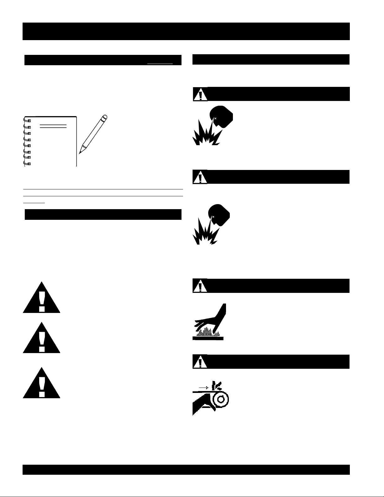
HAZARD SYMBOLS
SAFETY MESSAGE ALERT SYMBOLS
The three (3) Safety Messages shown below will inform you
about potential hazards that could injure you or others. The
Safety Messages specifically address the level of exposure to
the operator, and are preceded by one of three words: DANGER,
WARNING, or CAUTION.
L
Lethal Exhaust Gases
Engine exhaust gases contain poisonous
carbon monoxide. This gas is colorless and
odorless, and can cause death if inhaled.
NEVER operate this equipment in a confined
area or enclosed structure that does not
provide ample free flow air.
Explosive Fuel
Diesel fuel
vapors can cause an explosion if ignited. DO
NOT start the engine near spilled fuel or
combustible fluids. DO NOT fill the fuel tank
while the engine is running or hot. DO NOT
overfill tank, since spilled fuel could ignite if it
comes into contact with hot engine parts or
sparks from the ignition system. Store fuel in
approved containers, in well-ventilated areas
and away from sparks and flames. NEVER
use fuel as a cleaning agent.
is extremely flammable, and its
DANGER: You WILL be KILLED or
SERIOUSLY injured if you do not follow
directions.
WARNING: You CAN be KILLED or
SERIOUSLY injured if you do not follow
directions.
CAUTION: You CAN be injured if you
do not follow directions.
Potential hazards associated with this vibratory roller operation
will be referenced with Hazard Symbols which appear
throughout this manual, and will be referenced in conjunction
with Safety Message Alert Symbols.
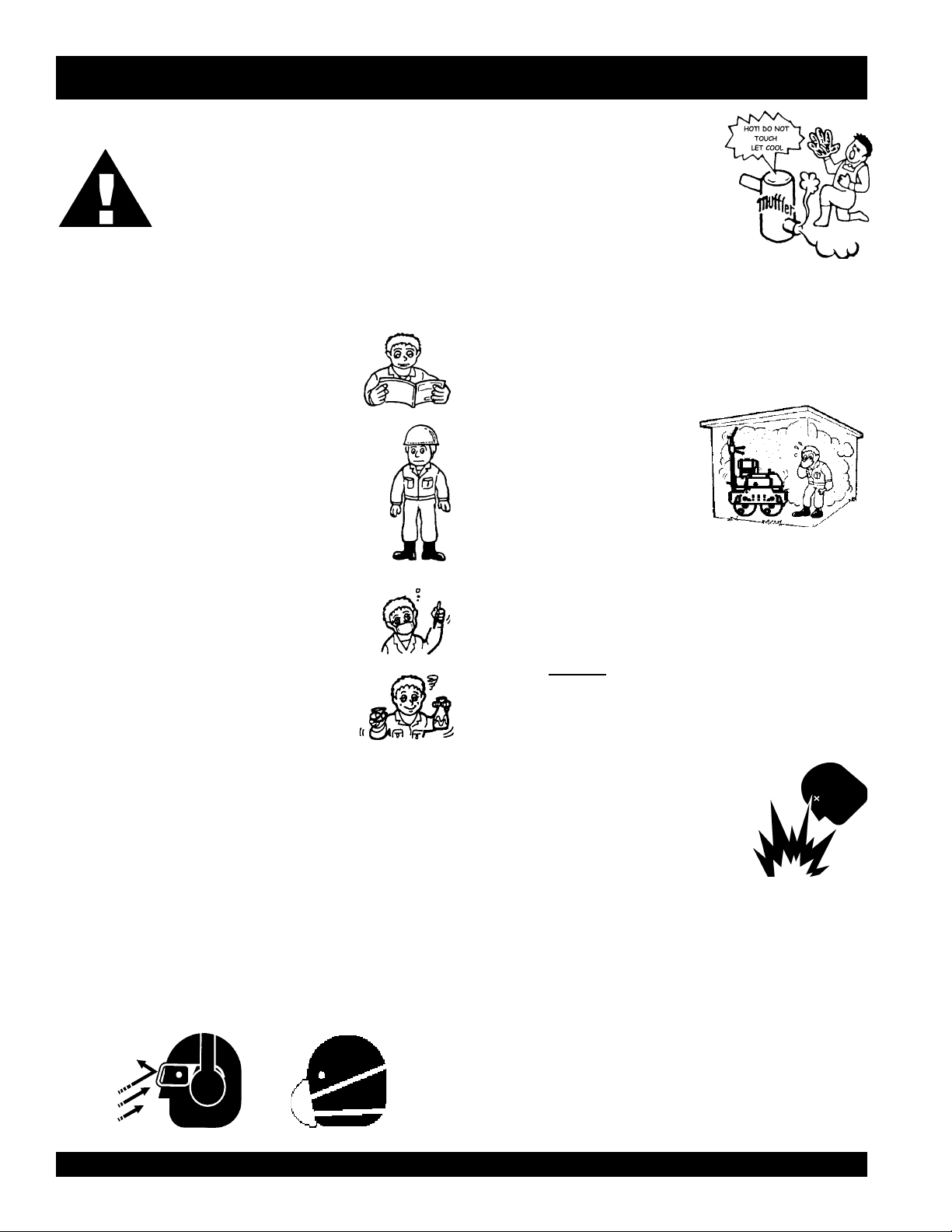
Burn Hazards
Engine components can generate extreme heat.
To prevent burns, DO NOT touch these areas
while the engine is running or immediately after
operations. Never operate the engine with heat
shields or heat guards removed.
Rotating Parts
NEVER operate equipment with covers, or
guards removed. Keep fingers, hands, hair and
clothing away from all moving parts to prevent
injury.
PAGE 6 — MQ-MIKASA MDR-9D VIBRATORY ROLLER — OPERATION AND PARTS MANUAL — REV. #0 (12/17/03)
Page 7
MDR-9D — SAFETY MESSAGE ALERT SYMBOLS
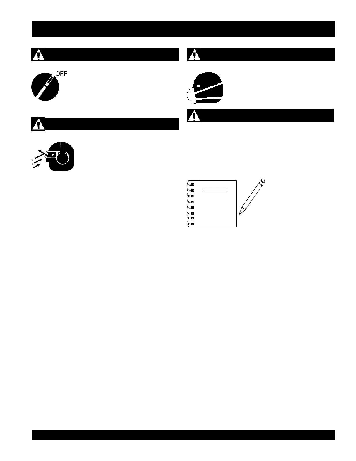
Accidental Starting
ALWAYS place the engine ON/OFF switch in
the OFF position, when the vibration roller is
not in use.
Sight and Hearing hazard
ALWAYS wear approved eye and hearing
protection.
Respiratory Hazard
ALWAYS wear approved respiratory
protection.
Equipment Damage Messages
Other important messages are provided throughout this manual
to help prevent damage to your vibration roller, other property,
or the surrounding environment.
NOTE
This vibratory roller, other
property, or the surrounding
environment could be
damaged if you do not follow
instructions.
MQ-MIKASA MDR-9D VIBRATORY ROLLER — OPERATION AND PARTS MANUAL — REV. #0 (12/17/03) — PAGE 7
Page 8
CAUTION:
MDR-9D — RULES FOR SAFE OPERATION
Failure to follow instructions in this manual
may lead to serious injury or even death! This
equipment is to be operated by trained and
qualified personnel only! This equipment is
for industrial use only.
The following safety guidelines should always be used when
operating the MIKASA MDR-9D Vibratory Roller.
GENERAL SAFETY
■
DO NOT operate or service this equipment before
reading this entire manual.
■
This equipment should not be operated by
persons under 18 years of age.
■
NEVER operate this equipment without proper
protective clothing, shatterproof glasses, steeltoed boots and other protective devices required
by the job. ALWAYS wear slip resistant safety
shoes or boots.
■
NEVER operate this equipment when not feeling
well due to fatigue, illness or taking medicine.
■
NEVER operate this equipment under the
influence or drugs or alcohol.
■
NEVER touch the hot exhaust manifold,
muffler or cylinder. Allow these parts to
cool before servicing engine or vibratory
roller.
■
High Temperatures – Allow the engine to cool before adding
fuel or performing service and maintenance functions. Contact
hot
with
■
The engine of this vibratory roller requires an adequate free
flow of cooling air. NEVER operate the vibratory roller in any
enclosed or narrow area where free flow of the air is restricted.
If the air flow is restricted it will
cause serious damage to the
vibratory roller or engine and
may cause injury to people and
property. Remember the roller’s
engine gives off DEADLY gases.
■
ALWAYS refuel in a well-ventilated area, away from sparks
and open flames.
■
ALWAYS use extreme caution when working with flammable
liquids. When refueling, stop the engine and allow it to cool.
DO NOT
explosion could result from fuel vapors, or if fuel is spilled on
a hot engine.
components can cause serious burns.
smoke around or near the machine. Fire or
■
NEVER operate the vibratory roller in an explosive
■
NEVER use accessories or attachments, which are not
recommended by Multiquip for this equipment. Damage to
the equipment and/or injury to user may result.
atmosphere or near combustible
materials. An explosion or fire could
result causing severe
bodily harm or
even death.
■
Manufacturer does not assume responsibility for any accident
due to equipment modifications.
■
Whenever necessary, replace nameplate, operation and
safety decals when they become difficult read.
■
ALWAYS wear proper respiratory (mask), hearing and eye
protection equipment when operating the vibratory roller.
PAGE 8 — MQ-MIKASA MDR-9D VIBRATORY ROLLER — OPERATION AND PARTS MANUAL — REV. #0 (12/17/03)
■
Topping-off to filler port is dangerous, as
it tends to spill fuel.
■
ALWAYS store the vibratory roller in a clean, dry location out
of the reach of children.
■
NEVER run engine without air cleaner. Severe engine
damage may occur.
■
NEVER leave the vibratory roller unattended, turn off engine.
■
CAUTION must always be observed while servicing this
vibratory roller. Rotating parts can cause injury if contacted.
■
DO NOT leave vibratory roller with engine running. Use
chock blocks if parking
vibratory roller on a grade.
Page 9
MDR-9D — RULES FOR SAFE OPERATION
■
NEVER disconnect any
These devices are intended for operator safety. Disconnection
of these devices can cause severe injury, bodily harm or even
death! Disconnection of any of these devices will void all
warranties.
Loading and Unloading (Crane)
■
Before lifting, make sure that machine parts (hook and
vibration insulator) are not damaged and screws are not
loosened or lost.
■
Always make sure crane or lifting device has been properly
secured to the hook of guard frame on vibratory roller.
■
NEVER lift the machine while the engine is running.
■
Use adequate lifting cable (wire or rope) of sufficient strength.
■
Use one point suspension hook and lift straight upwards.
■
NEVER allow any person or animal to stand underneath the
machine while lifting.
■
Try not to lift machine to unnecessary heights.
Transporting
"emergency or safety devices"
.
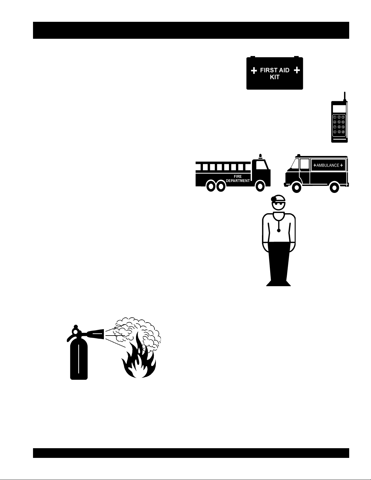
■
■
In emergencies
nearest phone or
Also know the phone numbers of the nearest
ambulance, doctor
information will be invaluable in the case of an
emergency.
ALWAYS know the location of the nearest and
always
know the location of the
keep a phone on the job site
and
fire department
. This
first aid kit
.
.
■
Always shutdown engine before transporting.
■
Tighten fuel tank cap securely and close fuel cock to prevent
fuel from spilling.
■
Drain fuel when transporting vibratory roller over long
distances or bad roads.
■
Always tie-down the vibratory roller during transportation by
securing the roller's guard frame with rope.
Emergencies
■
ALWAYS know the location of the nearest
fire extinguisher
Maintenance Safety
.
■
■
■
■
■
NEVER lubricate components or attempt service on a
running machine.
ALWAYS allow the machine a proper amount of time to
cool before servicing.
Keep the machinery in proper running condition.
Fix damage to the machine immediately and always replace
broken parts.
Dispose of hazardous waste properly. Examples of
potentially hazardous waste are used motor oil, fuel and
fuel filters.
■
DO NOT use food or plastic containers to dispose of
hazardous waste.
■
DO NOT pour waste, oil or fuel directly onto the ground,
down a drain or into any water source.
MQ-MIKASA MDR-9D VIBRATORY ROLLER — OPERATION AND PARTS MANUAL — REV. #0 (12/17/03) — PAGE 9
Page 10
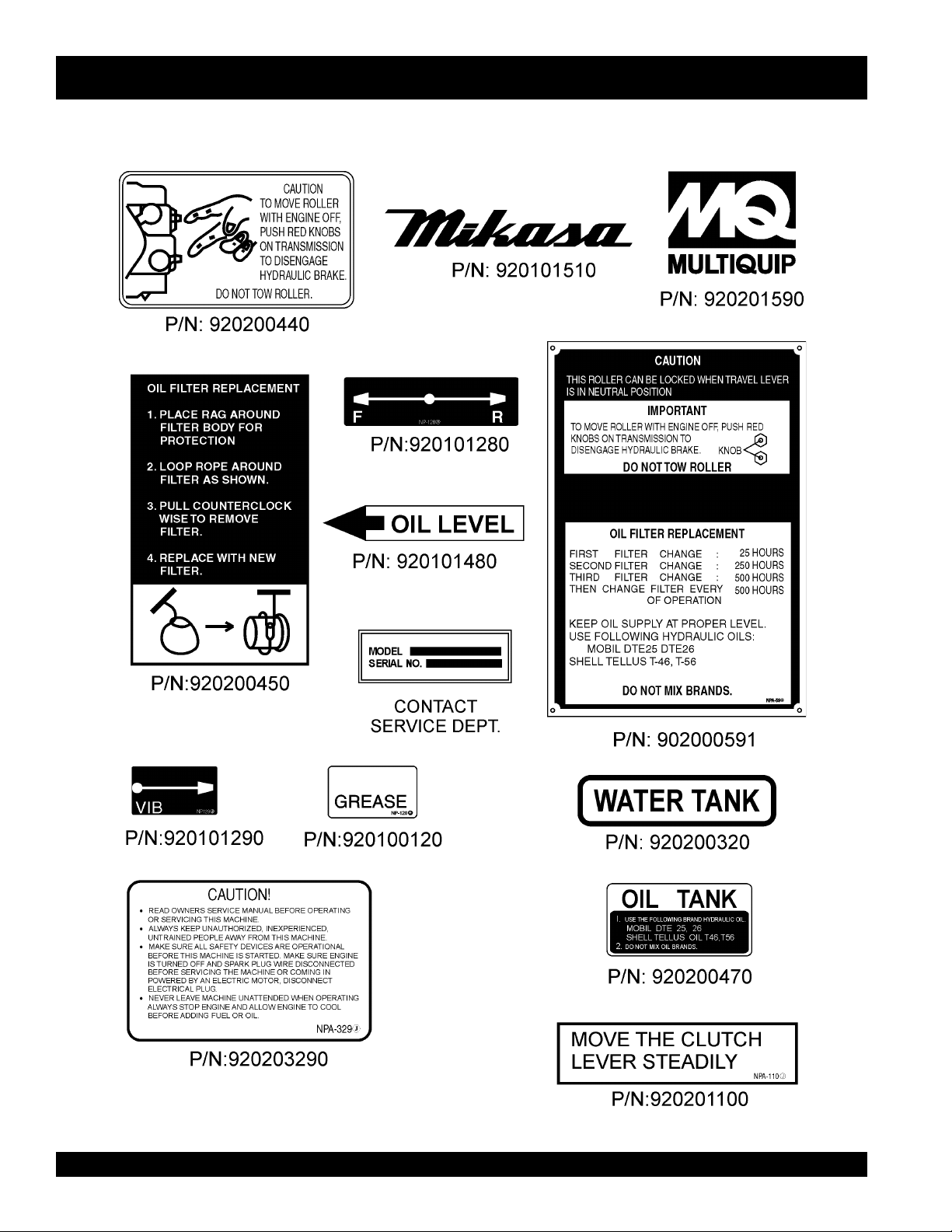
MDR-9D — OPERATION AND SAFETY DECALS
Figure 1 displays the operation and safety decals as they appear on the vibratory roller. Should any of these decals become
damaged or unreadable, contact the Multiquip Parts Department for a replacement set.
Figure 1. Operation and Safety Decals
PAGE 10 — MQ-MIKASA MDR-9D VIBRATORY ROLLER — OPERATION AND PARTS MANUAL — REV. #0 (12/17/03)
Page 11
.1elbaTRELLORYROTARBIVD9-RDM
MDR-9D — SPECIFICATIONS
SNOITACIFICEPS
dohteMgnitratS
ecroFlagufirtneC)gk000,3(.sbl006,6
ycneuqerFnoitarbiVmpv000,3
)esreverdnadrawrof(deepSgnilevarT)rh/mk3ot0(hpm8.1ot0
ytilibAedarG°52
relloRfohtdiWxretemaiD)mc007x754(ni6.72x81
esaBleehW)mm075(ni4.22
ecnaraelCdaoRediS)mm472(ni8.01
)eldnaHhtiw(htgneL)mm048,2(ni8.111
htdiW)mm597(ni3.13
thgieH)mm021,1(ni1.44
thgieWlatoT)gk088(.sbl049,1
noituloveRtupnIgnikroWmpr000,2
erusserPdetaRsuounitnoCmc/gk501(isp005,1
)D9-RDM(tratSeldnaHknarC
)SED9-RDM(tratScirtcelE
2
)
yticapaCknaTliO)sretil51(snollag4
yticapaCknaTretaW)sretil32(snollag6
2
ytilibAgnikroWm001,2
rh/
SNOITACIFICEPSENIGNE.2elbaT
ledoMZ18D1ztaH
epyT enignEleseiD,rednilyCelgniS,ekortS-4,delooc-riA
ekortSXeroB
tnemecalpsiDmc766(ni-uc07.04
enignE
tuptuOxaM.M.P.R0063/.P.H0.51
yticapaCknaTleuF)sretil0.7(snollag58.1
leuF2#leseiD
yticapaCliOebuL)sretil7.1(strauq8.1
dohteMgnitratScirtcelE/eldnaHknarC
hA.xam/.nimyrettaBhA07/54V21
noisnemiD
)HxWxL(
.ni43.3X.ni49.3
).mm58xmm001(
3
)
.ni00.32X26.91x13.41
).mm5.485X5.894X5.363(
thgieWteNyrD
).gK19(.sbl102
MQ-MIKASA MDR-9D VIBRATORY ROLLER — OPERATION AND PARTS MANUAL — REV. #0 (12/17/03) — PAGE 11
Page 12
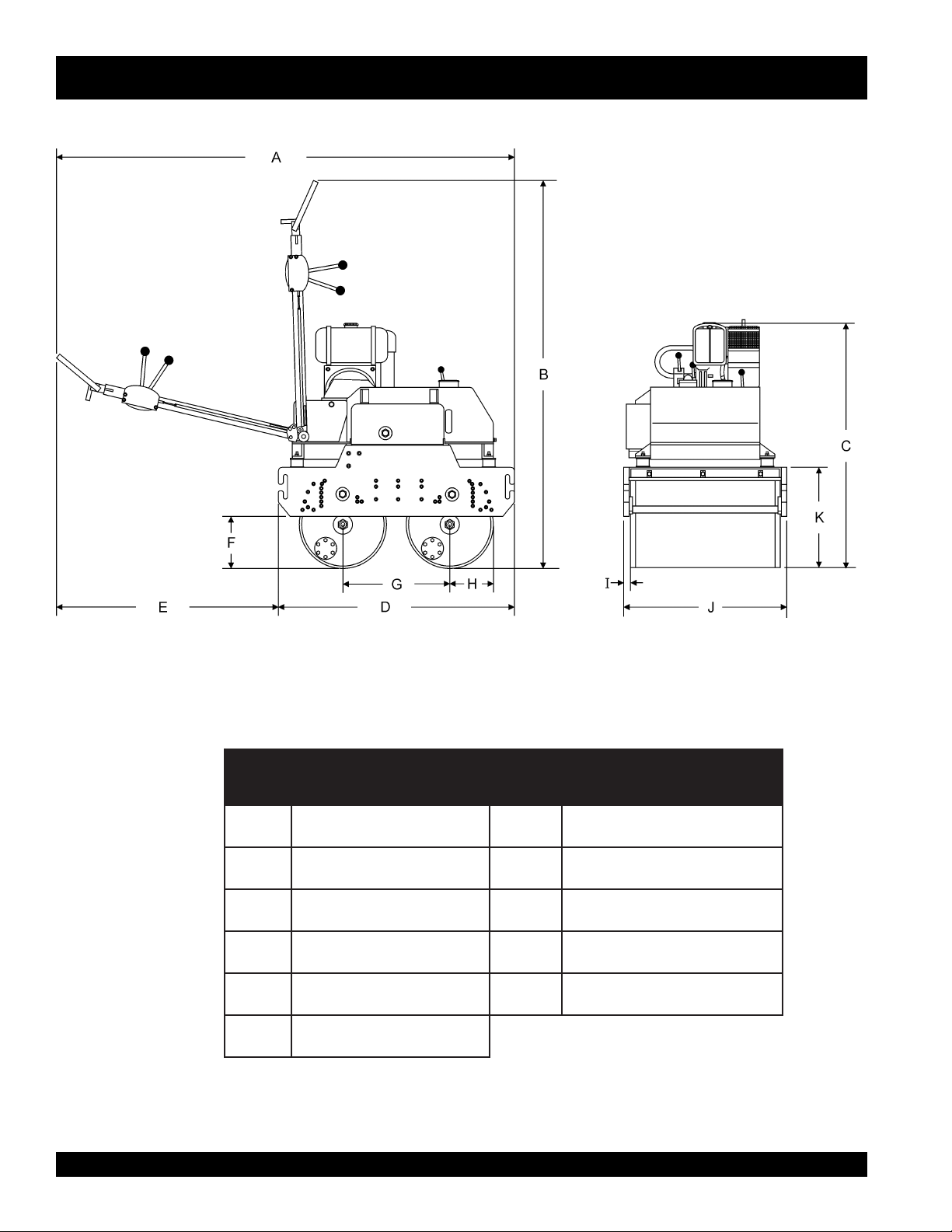
MDR-9D — DIMENSIONS
Figure 2. MDR-9D Vibratory Roller Dimensions
.FERSNOISNEMID.FERSNOISNEMID
A)sretem8.2(.ni8.111F )sretem75.(.ni4.22
B)sretem32.2(.ni88G )sretem754.(.ni81
C)sretem71.1(.ni64
D)sretem61.1(.ni9.54
E)sretem972.(.ni11
H
I
SNOISNEMIDRELLOR.3ELBAT
)sretem283.(.ni5.51
)sretem731.(.ni4.5
PAGE 12 — MQ-MIKASA MDR-9D VIBRATORY ROLLER — OPERATION AND PARTS MANUAL — REV. #0 (12/17/03)
Page 13

NOTE PAGE
MQ-MIKASA MDR-9D VIBRATORY ROLLER — OPERATION AND PARTS MANUAL — REV. #0 (12/17/03) — PAGE 13
Page 14
MDR-9D — GENERAL INFORMATION
The Mikasa Model MDR-9D is a powerful compacting tool
capable of applying a tremendous force in consecutive impacts
to a soil surface. With 28-inch drums nd 32 inches overall width,
virtually any asphalt or mixed granular soil compaction job is
quickly cut down to size.
The impact force of the MDR-9D levels and uniformly compacts
voids between soil particles to increase dry density.
Features include:
Hydraulic variable speed transmission assures easy
handling.
Deadman device which when pressed or hit will
cause the travel lever to return to neutral position
bringing the machine to a stop.
Non-corrosive water tank for the sprinkler system with a
capacity of 6 gallons.
Simple dual-lever controls assure operator safety and
convenience.
Sight gauge for hydraulic oil tank.
Front -mounted auxiliary travel lever.
Four large rubber shock mounts minimize vibrations to the
engine and hydraulics.
FREQUENCY/SPEED
The vibrating roller maximum frequency is 3000 vpm (vibrations
per minute). The forward and reverse travel speed of the vibratory
roller is approximately 1.8 mph (3 km/hour).
ENGINE
The Mikasa MDR-9D Vibratory Roller is equipped with a Hatz
1D81Z.
CONTROLS
Before starting the MDR-9D Vibratory Roller, identify and
understand the function of the controls and components as
indicated in Figure 6.
TRANSPORTATION
Adjustable transport hooks allow an operator to place the roller
on the tailgate of a dump truck without any assistance. The
control handle of the MDR-9D Vibratory Roller can be folded
vertically for ease of transport and storage.
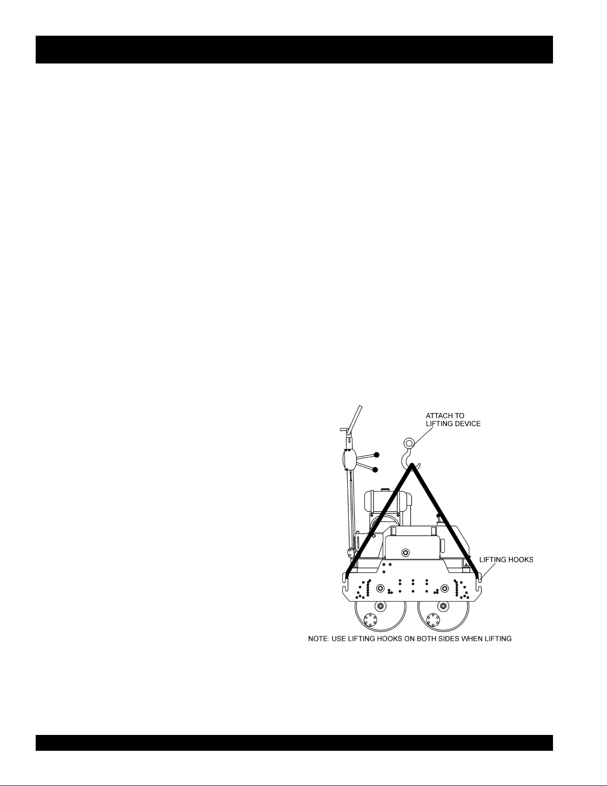
LIFTING THE ROLLER
When lifting of the roller is required (Figure 3), attach a suitable
hook or shackle to the
lifting device is capable of lifting 1,940 lbs (880 kg).
lifting hooks
of the roller. Make sure the
Convenient tie-downs, front and rear.
Scraper Bar.
Drum sprinkler system.
Handle folds to 90 degrees for storage and transport..
Figure 3. Lifting The Roller
PAGE 14 — MQ-MIKASA MDR-9D VIBRATORY ROLLER — OPERATION AND PARTS MANUAL — REV. #0 (12/17/03)
Page 15
MDR-9D — GENERAL INFORMATION
CAUTION :
NEVER! stand under, or get onto the roller
while it is being lifted or moved.
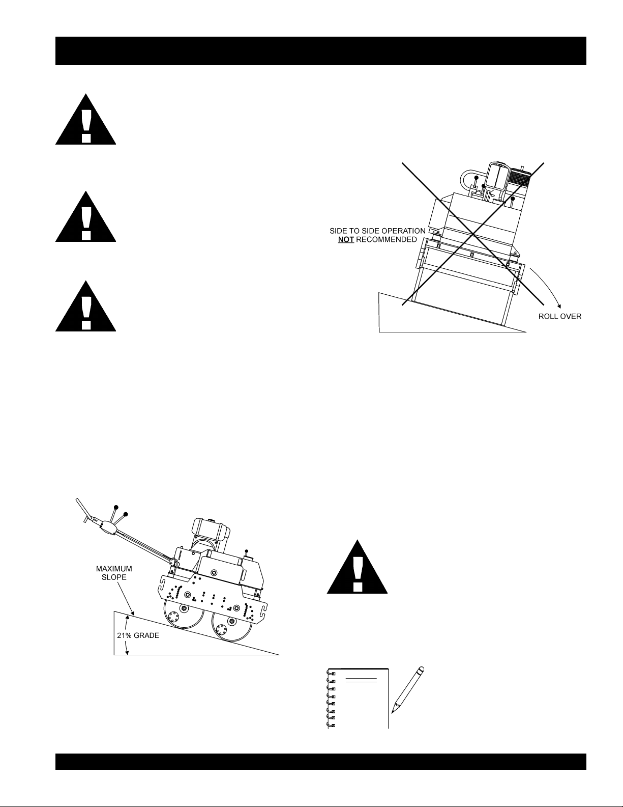
Tipping (Rollovers)
NEVER! operate the roller on side slopes (Figure 5). The
possibility exist that the roller could tip over (roll over), thus
causing bodily harm even death and serious damage to the
equipment.
CAUTION :
ONLY! use steel ropes or chains that are
capable of lifting at least 1,940 lbs. (880 kg ).
CAUTION :
NEVER! use any other part of the roller for
lifting purposes. Use the lifting eye. Using other
parts of the roller for lifting will cause severe
damage to the roller,
OPERATING ON SLOPES
Special care must be taken when operating the roller on hills or
slopes. There exist the possibility of serious injury to the operator
and severe damage to the roller in the event of a roll over.
ALWAYS operate the roller up and down hills rater than from
side to side. For safe operation hillside slopes should not exceed
12 degree (21 % grade). See Figure 4 below.
In the event the roller does tip over, extreme care must be taken
to prevent damage to the engine. When the roller has been
tipped over, oil from the engine crankcase can flow into the
combustion chamber, which can severely damage the engine
the next time it is started.
IMMEDIATELY after a unit has tipped over upright the unit as
soon as possible to prevent oil from leaking into the combustion
chamber.
Figure 5. Recommended Slope
CAUTION :
To prevent damage to the engine after a
rollover, the unit must NOT be started. NEVER
start a unit after a rollover. CONTACT your
nearest authorized Multiquip dealer for
instructions or servicing.
Figure 4. Recommended Slope
NOTE
MQ-MIKASA MDR-9D VIBRATORY ROLLER — OPERATION AND PARTS MANUAL — REV. #0 (12/17/03) — PAGE 15
NEVER! operate the roller on
. The roller may tip over causing
slopes
injury to personnel and severe damage
to the equipment
side
Page 16
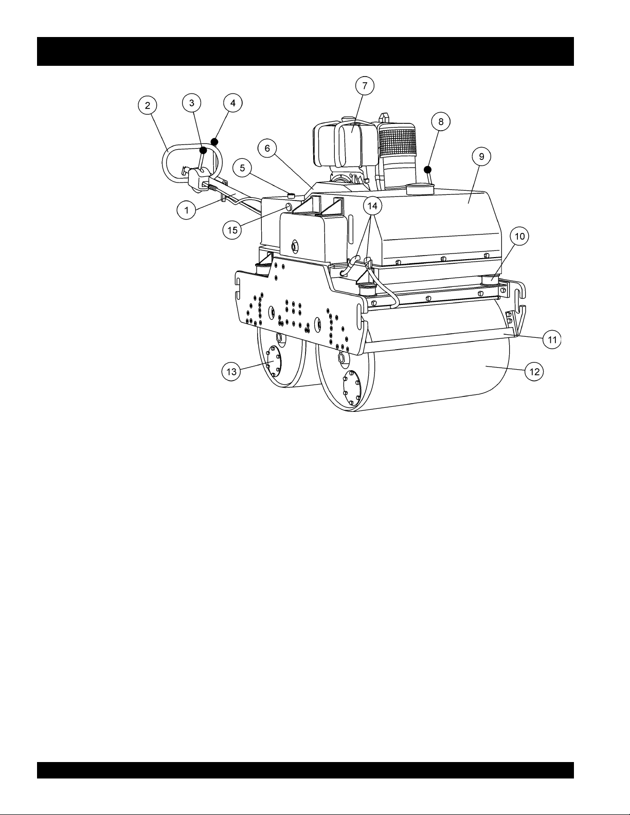
MDR-9D — VIBRATORY ROLLER COMPONENTS
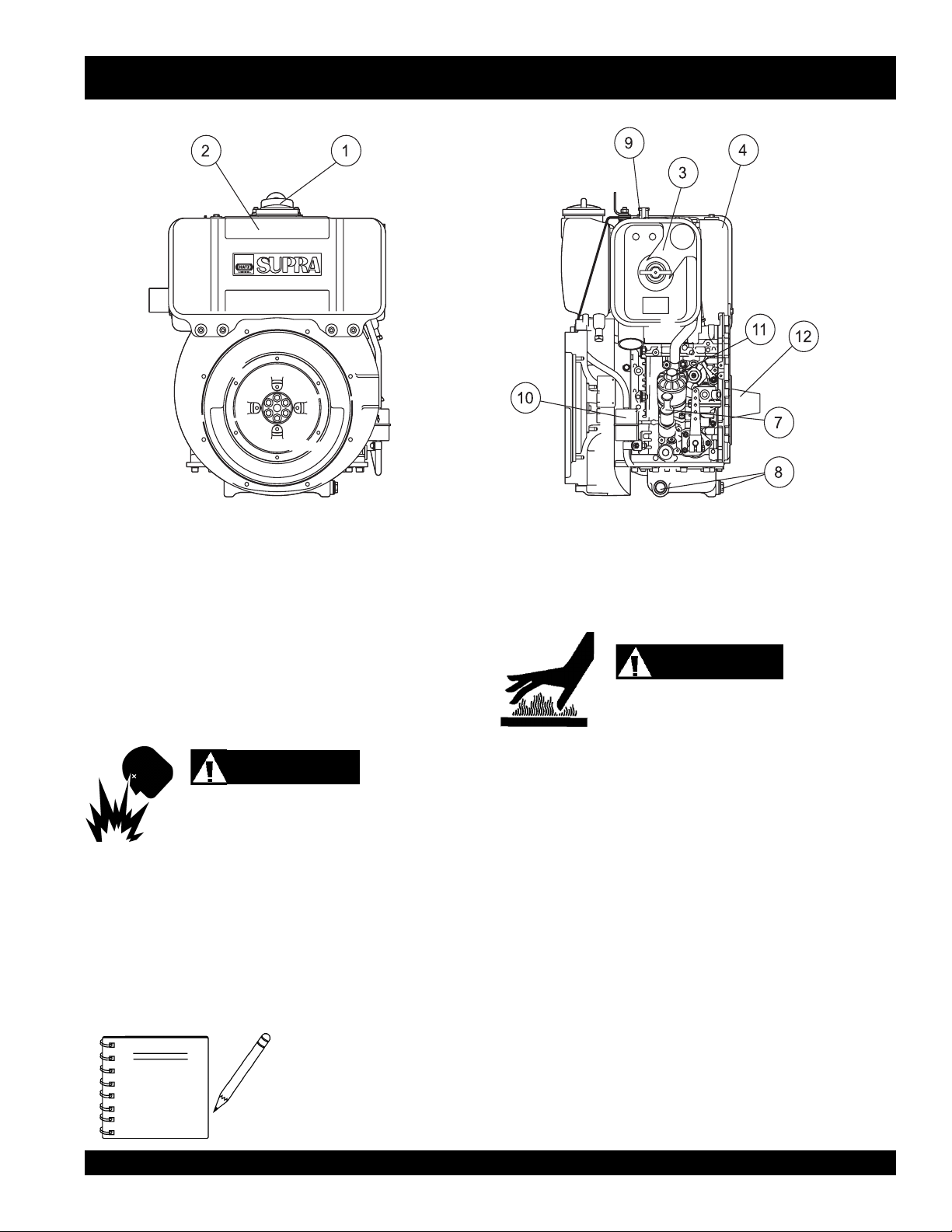
Figure 6. MDR-9D Vibratory Roller
Components
Figure 6 illustrates the location of the major components
for the MDR-9D Vibratory Roller. The function of each
component is described below:
1. Handle Bar – When operating the roller, this handle is to
be in the downward position. When the roller is to be
stored
, move the handle bar to the upright position.
2. Hand Grip – When operating the roller, use this hand grip
to maneuver the roller. Also has dead man device, when
pressed or hit while traveling in reverse, causes the travel
lever to return to neutral position to stop the machine.
Push
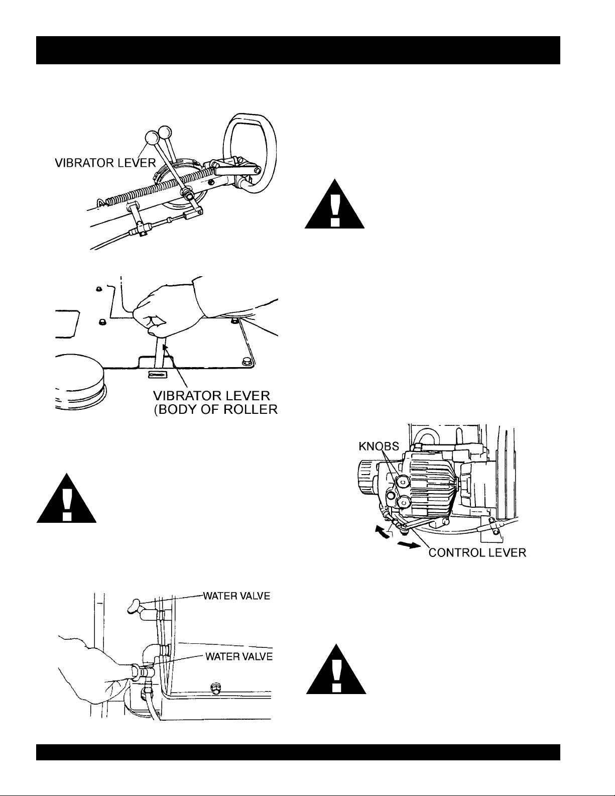
3. Travel Lever –
in a forward direction,
will move in backwards direction. Placing the lever in the
middle (midway) will cause the roller not to move (neutral).
4. Vibrator Lever – Turns the vibration on and off.
5. Hydraulic Oil Tank/Cap – Stores hydraulic fluid. Open cap
to fill with recommended hydraulic oil (Shell Tellus #46).
6. V-Belt Cover – Remove this cover to gain access to the
v-belts. NEVER run the vibratory roller without the v-belt
cover. If the v-belt cover is not installed, the possibility exist
that your hand may get caught between the v-belt and clutch,
thus causing serious injury and bodily harm.
the lever forward, the roller will move
pull
the lever backwards, the roller
7. Engine – This vibratory roller uses a HATZ 1D81Z diesel
engine. Refer to the owner’s manual for engine information
and related topics.
8. Vibrator Lever (on the body of machine) – Turns the
vibration on and off.
9. Water Tank – Holds 6 gallons (23 liters) of water for the
sprinkler system.
10. Shock Absorber -
11. Scraper Bar – This bar helps prevent buildup of material
between the drum and the frame.
12. Vibration Rollers – 18-inch diameter steel drums that
provide the compaction force in the compaction and
patching of asphalt-type surfaces.
13. Checking Cover for Chains – Take off the cover to check
and lubricate chains.
14. Water Valves– Turn on the water sprinkling system.
15. Hydraulic Oil Gauge – Indicates the hydraulic oil level.
PAGE 16 — MQ-MIKASA MDR-9D VIBRATORY ROLLER — OPERATION AND PARTS MANUAL — REV. #0 (12/17/03)
Page 17
MDR-9D — HATZ 1D81Z ENGINE COMPONENTS
Figure 7. HATZ 1D81Z Engine Components
ENGINE COMPONENTS
Figure 7 illustrates the location of the major engine
components of the machine. Each component is described
below:
1. Fuel Filler Cap – Remove this cap to add diesel fuel to the
fuel tank. Make sure cap is tighten securely. DO NOT over
fill.
DANGER
Adding fuel to the tank should be done only when
the engine is stopped and has had an opportunity
to cool down. In the event of a fuel spill, DO NOT attempt to start the
engine until the fuel residue has been completely wiped up, and the
area surrounding the engine is dry.
2. Fuel Tank – Diesel engine holds 5.8 quarts of diesel fuel.
3. Air Cleaner – Prevents dirt and other debris from entering
the fuel system. Remove wing-nut on top of air filter
cannister to gain access to filter element.
Operating the engine without
an air filter, with a damaged air
NOTE
filter, or a filter in need of
replacement will allow dirt to
enter the engine, causing rapid
engine wear.
4. Muffler – Used to reduce noise and emissions.
while the engine is running or immediately after operating. NEVER
operate the engine with the muffler removed.
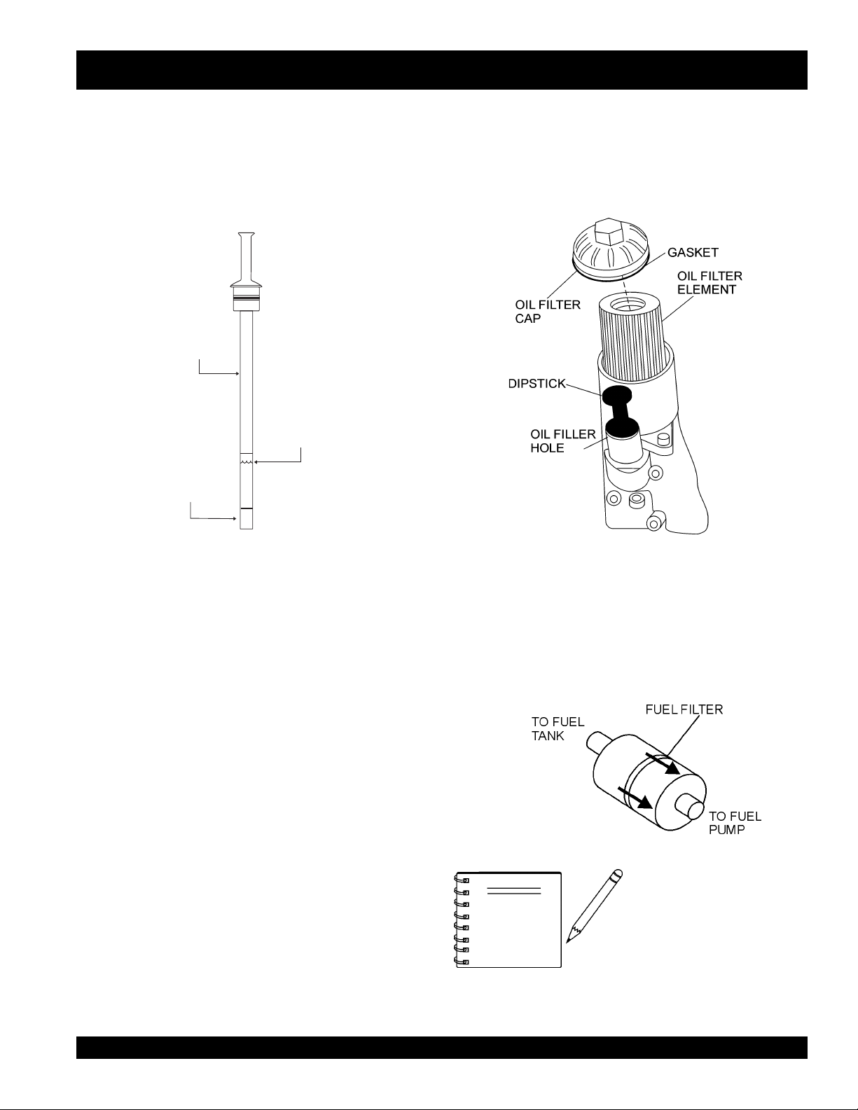
7. Oil Filler Cap/Dipstick – Remove this cap to add oil to the
oil tank. Use dipstick to check oil level.
8. Oil Drain Plug – Unscrew plug to drain oil from engine
crankcase. Dispose of oil in a safe manner.
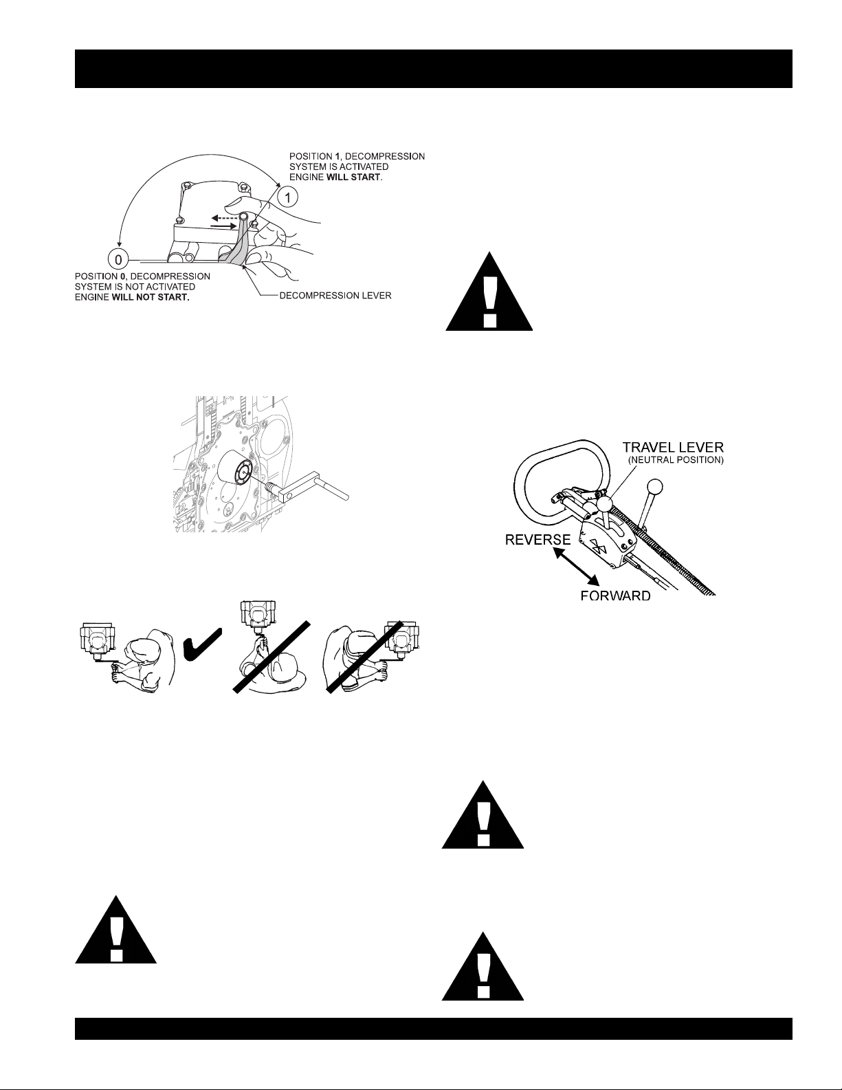
9. Decompression Lever – Press down before starting
engine. To prevent damage to the engine, DO NOT use for
any other purpose.
10. Fuel Filter – Controls the flow of diesel fuel to the carburetor.
Must be in the ON position when starting and running the
engine.
11. Oil Filter – filters oil for contaminates. Replace as necessary.
12. Starting Handle Guide Sleeve – Insert starting handle
into the guide sleeve and turn to crank start engine.
WARNING
Engine components can generate extreme heat.
To prevent burns, DO NOT touch these areas
MQ-MIKASA MDR-9D VIBRATORY ROLLER — OPERATION AND PARTS MANUAL — REV. #0 (12/17/03) — PAGE 17
Page 18
MDR-9D — INSPECTION
CAUTION :
Never operate the vibratory
roller in a confined area or
3. If the oil level is low, fill to the edge of the oil filler
hole with the recommended oil type (Table 4).
Maximum oil capacity is 2 quarts (1.9 liters).
enclosed structure that does
not provide ample
free flow
of air.
ALWAYS wear approved eye and hearing
protection before operating the vibratory roller.
BEFORE STARTING
1. Read safety instructions at the beginning
of manual.
2. Familiarize yourself with the operating
and control elements of the machine and
the working environment. This includes obstacles in the
working area, bearing capacity of the ground and the
DANGER
necessary safety provisions.
3. Check the air filter for dirt and dust. If the air filter is dirty, replace
air filter with a new one as required.
4. Check fastening nuts and bolts for tightness. Loose threads
may cause damage to the machine when vibrating.
CHECKING FUEL
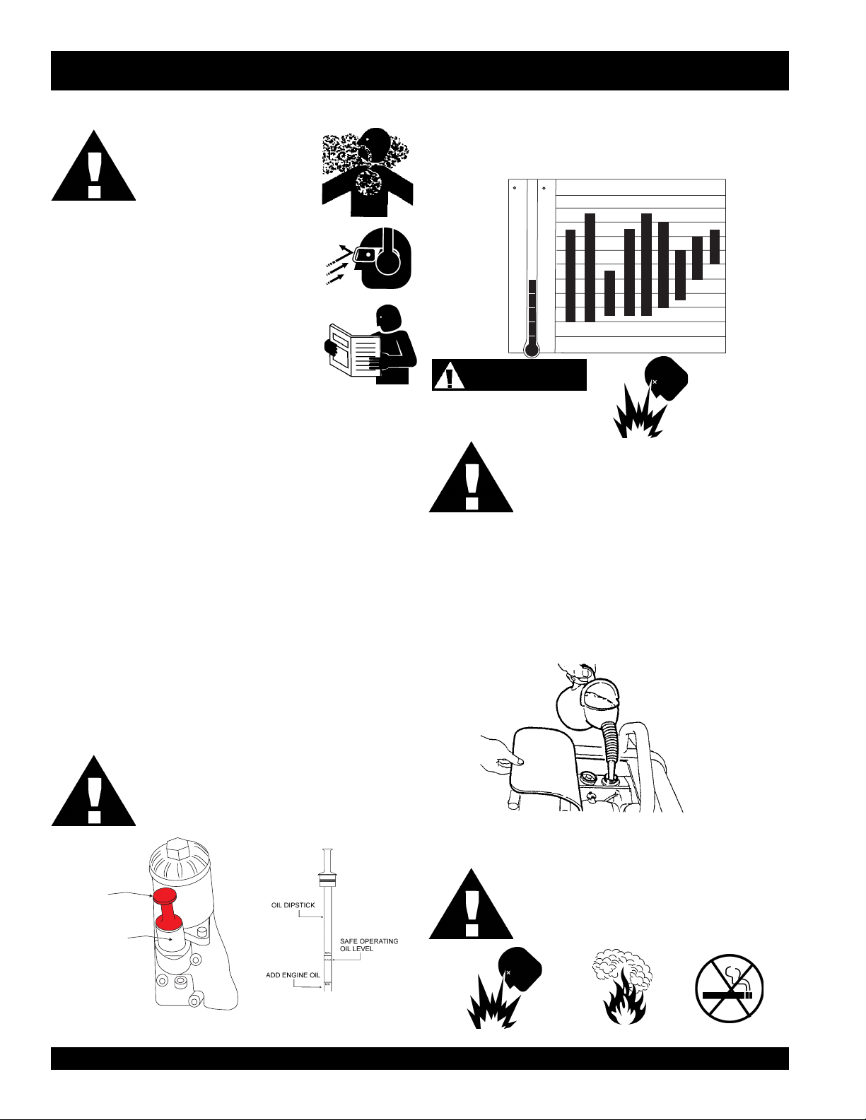
Table 4. Oil Selection Chart
5W/30
5W/40
OIL: SAE
10W/30
10W
10W/40
15W/40
30
20W/20
40
F
C
122
50
104
40
86
30
68
20
10
50
032
-10
-14
-20
-4
-30
-22
-40
-40
Explosive Fuel
Explosive Fuel
Diesel fuel is highly flammable and can be dangerous if mishandled. DO NOT smoke while
refueling. DO NOT attempt to refuel the vibratory
hot!
or
roller if the engine is
running.
5. Understand the geographical features and regulations of
1. Remove the fuel cap located on top of fuel tank.
the job site.
6. Clean the vibratory roller, removing dirt and dust,
particularly, the bottom of the plate, engine cooling air inlet.
CHECKING ENGINE OIL LEVEL
1. Make sure that the machine is situated in a flat
2. Visually inspect to see if fuel level is low. If fuel is low, replenish
with diesel fuel (Figure 9).
3. When refueling, be sure to use a strainer for filtration. DO
NOT top-off fuel. Wipe up any spilled fuel.
surface so that level measurements will be accurate.
2. Pull out the dipstick from the oil tank (Figure 8).
CAUTION :
DO NOT overfill oil tank. This could cause oil
leaks and sluggish operation. Clean cap and
surrounding area before opening to prevent
dirt from entering tank.
DANGER
ENGINE OIL
DIPSTICK
HOLDER
Figure 9. Refueling
Fuel spillage on a hot engine can case a
explosion
. If fuel spillage occurs, wipe up the
fire
or
spilled fuel completely to prevent fire hazards.
NEVER!
smoke around or near the roller.
Figure 8. Oil Dipstick
PAGE 18 — MQ-MIKASA MDR-9D VIBRATORY ROLLER — OPERATION AND PARTS MANUAL — REV. #0 (12/17/03)
Page 19
MDR-9D — INSPECTION
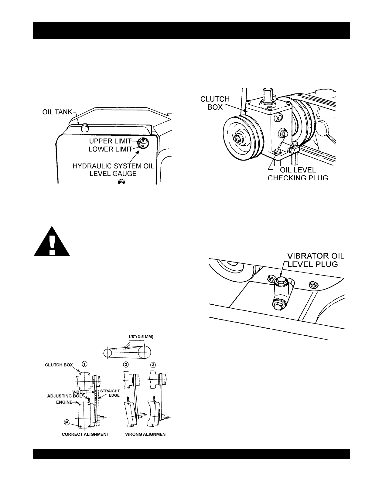
CHECKING HYDRAULIC SYSTEM
1. Check the oil tank level gauge (Figure 10). Oil level
should be at the middle indication of the gauge or
higher. Fill as required
2. Check the surroundings of the oil tank, hydraulic
pump and motor for oil leakage.
Figure 10. Hydraulic System Oil Level Gauge
DANGER
ALWAYS keep hands and fingers away from
pinch points. DO NOT allow anyone to reach
in on dangerous sections of the machine to
avoid any accidents.
CHECKING THE CLUTCH BOX OIL LEVEL
1. Check clutch box for any oil leakage.
2. Remove the level plug and check oil level (Figure 12).
3. Add oil if necessary.
CHECKING THE VIBRATOR OIL LEVEL
1. Remove the red filler plug and the oil level inspection hole
plug from the vibrator case (Figure 13).
2. Fill with oil until oil overflows from inspection hole.
Figure 12. Clutch Box Oil Level Check
CHEKCING THE V-BELT
1. Check all bolts and screws and make sure all are
securely tightened.
2. Check V-belt for proper tension. The normal slack
should be approximately 1/8 inch (3 to 5 mm) when
the belts are forcibly depressed between the two
sheaves (Figure 11). Insufficient tension causes
weak vibration and machine damage.
Figure 11. V-Belt Tension
Figure 13. Vibrator Oil Level Check
MQ-MIKASA MDR-9D VIBRATORY ROLLER — OPERATION AND PARTS MANUAL — REV. #0 (12/17/03) — PAGE 19
Page 20
MDR-9D — INSPECTION/START-UP
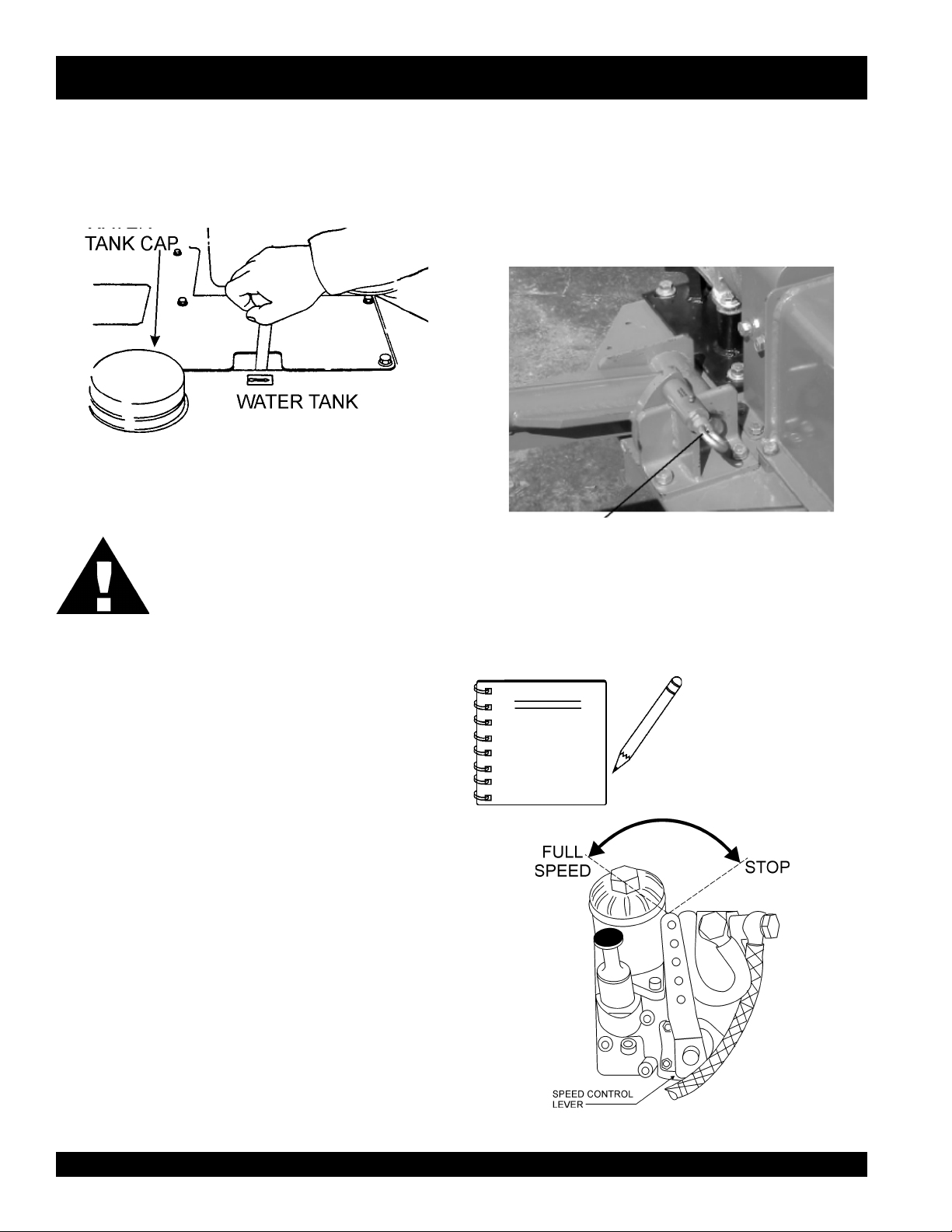
CHECKING WATER TANK
1. Check the water tank to see if filled. Add water if necessary.
The water tank has a capacity of approximately 6gallons
(23 liters) (Figure 14).
Figure 14. Water Tank Check
CAUTION
Be careful not to confuse the water tank with
the oil tank.
POSITIONING THE HANDLE BAR
1. Release the handle bar release pin (Figure 15) and position
the handle bar to the lowered position before starting
operation.
2. When machine is not in use, release the handle bar release
pin and position the handle bar to the upright position.
Handle Bar
Release Pin
Figure 15. Handle Bar Positioning
INITIAL STARTUP (Crank Handle Start)
1. Set the
CHECKING LEVERS
1. Check travel and vibrator levers to make sure they are
functioning properly (Figure 6).
2. With travel lever placed in reverse, push the deadman
device and verify that the travel lever returns to neutral
position. The travel lever stays in neutral position once the
deadman device is released.
CHECKING SCRAPER BAR
1. Check scraper barand make sure that they are not clogged
with mud, bent or damaged (Figure 6).
2. Adjust clearance between drums and scrapers as
necessary.
CHECKING BOLTS, NUTS, AND SCREWS
1. Check bolts, nuts, and screws on various parts of the
machine, including the engine, for proper tightness.
half way between start and stop.
Speed Control Lever
NOTE
(Figure 16 to a position
Selecting a lower engine
speed will reduce smoke
when starting.
Figure 16. Speed Control Lever
PAGE 20 — MQ-MIKASA MDR-9D VIBRATORY ROLLER — OPERATION AND PARTS MANUAL — REV. #0 (12/17/03)
Page 21
MDR-9D — START-UP
2. Pull up decompression lever (Figure 17) to position
1 and release.
Electric Start
1. Turn the key to the "START" position until the engine starts.
If the engine fails to start within 5 seconds, release the key, and
wait at least 10 seconds before operating the starter again
TRAVELING
CAUTION
Figure 17. Decompression Lever
3. Insert the starting handle into the engine’s starting
handle guide sleeve (Figure 18).
1. To make the roller move in the forward direction push the
travel lever ( Figure 20) forward. This roller has a hydraulic
variable speed transmission. By moving the travel lever
varioys increments, you can vary the speed from 0 to 1.8 mph
(0 to 3 km/hr).
Make sure to follow all safety rules referenced in
the safety section of this manual before operating
roller. Keep work area clear of debris and other
objects that could cause damage to the roller or
bodily injury.
Figure 18. Starting Handle Guide Sleeve
4. When turning the starting handle, observe the correct
operating position (Figure 19).
2. To make the roller move in the reverse direction pull the travel
lever ( Figure 20) backwards.
3. Firmly gasp the roller's hand grip, the roller will begin moving
Figure 19. Starting Handle Operating Position
5. Grasp the starting handle firmly in both hands and
turn counterclockwise at increasing speed. Five turns
of the starting handle are needed to build up enough
compression to start the engine.
6. Once the engine starts, stop cranking and remove
the starting handle from the guide sleeve.
in the desired position when the direction lever has been
placed in the desired position.
CAUTION
CAUTION :
There is a risk of injury from the rotating star ting
handle. When using the starting handle, keep
the body clear of the handle to avoid being
struck. If the engine backfires because the
handle was not turned firmly enough release
the starting handle immediately and stop the
engine.
CAUTION
Figure 20. Travel Lever
DO NOT reduce speed during work.
When shifting travel lever from forward
to reverse, be sure to stop the lever at
the neutral position first before moving
the lever to the opposite direction. DO
NOT shift the lever from forward to
reverse (or reverse to forward) in one
motion.
After test travel, shut down engine and
check for any problems including oil
leakage. If any trouble is found, correct
the problem before attempting to operate
the roller again.
MQ-MIKASA MDR-9D VIBRATORY ROLLER — OPERATION AND PARTS MANUAL — REV. #0 (12/17/03) — PAGE 21
Page 22
MDR-9D — OPERATION
VIBRATING
1. Shift the two vibrator levers (Figures 21 and 22) to the
vibrate position to start vibrations.
STOPPING
1. Place the vibrator and travel levers to the neutral position.
2. Slow down the engine and allow to cool for at least 2
minutes. Place
and listen for the engine to stop running.
CAUTION :
Figure 21. Vibrator Lever
3. The hydraulic brake is automatically engaged when the
travel lever is in neutral position. When parked on a slope
with the engine turned off, place a block against the
roller drum to prevent the roller from moving.
UNLOADING
1. If you need to move the roller by pushing it manually
once engine is stopped, push in the upper and lower
knobs of the transmission check valve. This will
cause the hydraulic break to disengage and allow
the roller to be moved without causing
damage(Figure 24).
speed control lever
NEVER attempt to stop the engine by
moving the decompression lever. Always
use the speed control lever to stop engine.
in the stop position
Figure 22. Vibrator Lever (Body)
CAUTION :
Using vibration with clutch slipping
causes the clutch to burn. Also, vibration
should NOT be used over completely
compacted area, paved road surface, or
with stationary roller.
WATERING
1. To operate water sprinkling system, turn on the front and
rear water valves on the side of the roller. (Figure 23).
Figure 24. Disengaging Hydraulic Brake
2. After moving, reset upper and lower knobs.
CAUTION :
NEVER tow roller with any type of vehicle.
Doing so will damage the hydraulic
system.
NEVER perform unloading procedure on
a slope. This may cause roller to roll down
if parking brake or blocking is deficient.
Figure 23. Water Valves
PAGE 22 — MQ-MIKASA MDR-9D VIBRATORY ROLLER — OPERATION AND PARTS MANUAL — REV. #0 (12/17/03)
Page 23

MDR-9D — LIFTING/TRANSPORTING
LIFTING
1. Use a crane or lift to load and unload the machine. A
skilled crane operator is required to perform the job.
2. When lifting the machine, check for any damaged or
loose bolts, lifting hooks, and shock mounts.
3. Check any damaged or loose bolts in the guard frame to
avoid machine sliding off.
4. Make sure that the machine is shut off before machine is
lifted.
5. Use reliable cable for lifting.
6. Always lift the machine vertically and keep the
machine away from workers and animals.
7. Do not lift the machine higher than the required
height.
TRANSPORTING
1. Always make sure that the machine is shut off while
being transported.
2. Check that the fuel cap is properly closed and
tightened.
3. When traveling long distances or on rugged terrain,
drain the fuel of the machine before transporting.
4. Tie down the machine securely on the
transportation so that it will not move or topple over.
MQ-MIKASA MDR-9D VIBRATORY ROLLER — OPERATION AND PARTS MANUAL — REV. #0 (12/17/03) — PAGE 23
Page 24
CAUTION:CAUTION:
CAUTION:
CAUTION:CAUTION:
MDR-9D — MAINTENANCE
CAUTION:CAUTION:
CAUTION:
CAUTION:CAUTION:
Inspection and other services should
always
be carried out on hard and level ground with
the engine shutdown.
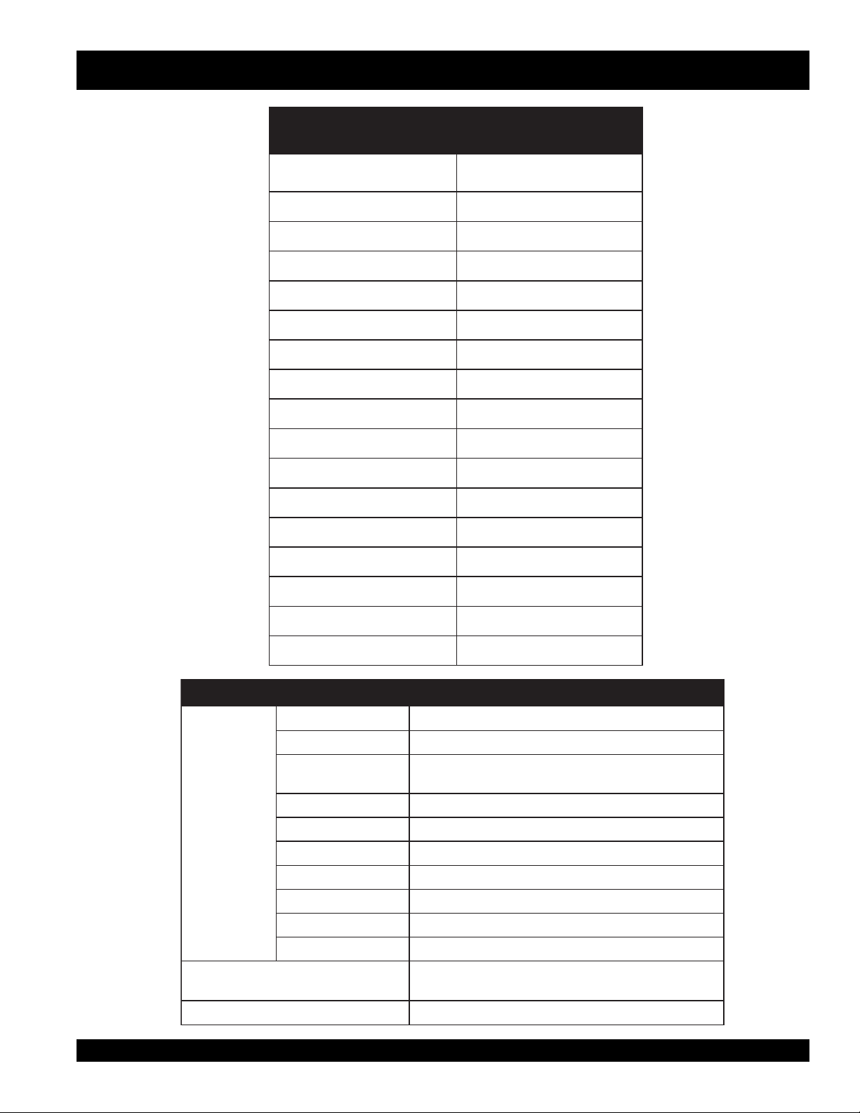
INSPECTION AND MAINTENANCE SERVICE TABLES
1. To make sure your plate vibratory roller is always in good
working condition before using, carry out the maintenance
inspection in accordance with Tables 4 through 6.
D9-RDM.5ELBATNOITCEPSNIENIHCAM
METI
gnissiMroesooL
swercS
straPdegamaD
gnillortnoCfonoitcnuF
traPmetsyS
noisneTniahC
tnemtsujdA
retliFliOciluardyH
tnemecalpeR
FOSRUOH
NOITAREPO
sruoh8yrevE
)yadyreve(
sruoh8yrevE
)yadyreve(
sruoh8yrevE
)yadyreve(
sruoh05yrevE62egapeeS
52retfayllaitinI
yreveneht,sruoh
2(sruoh052
yreve,)shtnom
4(sruoh005
yreve,)shtnom
sruoh000,1
.retfaereht
SKRAMER
82egapeeS
Fuel piping and connections should be
replaced every 2 years.
D9-RDM.6ELBATKCEHCENIGNE
METINOITAREPOFOSRUOH
kaeLleuFroliO)yadyreve(sruoh8yrevE
gninetsaFfossenthgiT
sdaerhT
dnakcehCliOenignE
tnemhsinelpeR
gninaelCretliFriAyliaD
tnemecalpeRliOenignE
retliFliOenignE
tnemecalpeR
tnemecalpeRretliFleuFsruoh005yrevE
)level
sruoh
sruoh052yrevE
)yadyreve(sruoh8yrevE
)yadyreve(sruoh8yrevE
.kcehcenignenosliatedroflaunamenigneetarapeseeS
DAILY SERVICE
z
Check for leakage of fuel or oil.
z
Check for loose screws including tightness. See Table 6
below (tightening torque ), for retightening:
mumixamdeificepsothsinelpeR(
052yrevenehtsruoh52tsrifretfA
liOciluardyH
tnemecalpeR
CAUTION:CAUTION:
CAUTION:
CAUTION:CAUTION:
ot4yreve,yllaitinI
enoretfA.sruoh5
kcehCliOciluardyH
kcehChctulCnoitarbiVyrassecensA72egapeeS
These inspection intervals are for operation
under normal conditions. Adjust your inspection
intervals based on the number hours vibratory
roller is in use, and particular working
conditions.
.yadaeciwt,keew
,skeew2retfA
.yadaecno
ot000,1yrevE
sruoh005,1
72egapeeS
T4 07 051 003 005 057 001,1 004,1 000,2
T8-6 001 052 005 008 003,1 000,2 007,2 008,3
72egapeeS
T11 051 004 008 002,1 000,2 009,2 002,4 006,5
* 001
z
z
z
mm6 mm8 mm01 mm21 mm41 mm61 mm81 mm02
lairetaM
~003
~056
053
007
)munimulafositrap-retnuocesacnI(*
Remove soil and clean the bottom of roller.
Check the levers, cables and linkage.
Check engine oil.
)mc/gk.ni(EUQROTGNINETHGIT.7ELBATRETEMAID
)dednahthgirllaeraenihcamsihthtiwesunisdaerhT(
.wercsdna,tlobhcaenodekramsilairetamfoytilauqdnalairetaM
PAGE 24 — MQ-MIKASA MDR-9D VIBRATORY ROLLER — OPERATION AND PARTS MANUAL — REV. #0 (12/17/03)
Page 25
MDR-9D — MAINTENANCE
CHECKING ENGINE OIL LEVEL
Check the engine crankcase oil level prior to each use, or
when the fuel tank is filled. Make sure the pump is level. The
oil level must be between the two notches on the dipstick
as shown in Figure 25.
OIL DIPSTICK
SAFE OPERATING
OIL LEVEL
MAX
ADD ENGINE OIL
MIN
CHANGING ENGINE OIL FILTER
Change the engine oil filter (Figure 26) and gasket after 250
hours of operation. To gain access to the oil filter element,
unscrew the oil filter cap and replace the oil filter element.
Make sure to tighten oil filter cap securely.
Figure 25. Engine Oil Dipstick
CHANGING ENGINE FUEL FILTER
CHANGING ENGINE OIL
Change engine oil after first 25 hours of operation. Drain and
refill engine crankcase with the correct type and amount oil
(reference Table 3) after 250 hours of operation hours or once
Replace fuel filter (Figure 27) and drain fuel tank to remove
water and sediment every 500 hours. If the purity of the fuel
being used is of lesser quality replace fuel filter more often
as needed.
a week thereafter.
When draining engine crankcase oil, place oil into a suitable
container while engine is still warm. Replace the drain plug
tightly. Add oil through the filler hole.
NOTE
Figure 26. Oil Filter Element
Figure 27. Fuel Filter
When re-installing fuel filter,
please note the arrows
indicating the direction of
fuel flow.
MQ-MIKASA MDR-9D VIBRATORY ROLLER — OPERATION AND PARTS MANUAL — REV. #0 (12/17/03) — PAGE 25
Page 26
MDR-9D — MAINTENANCE
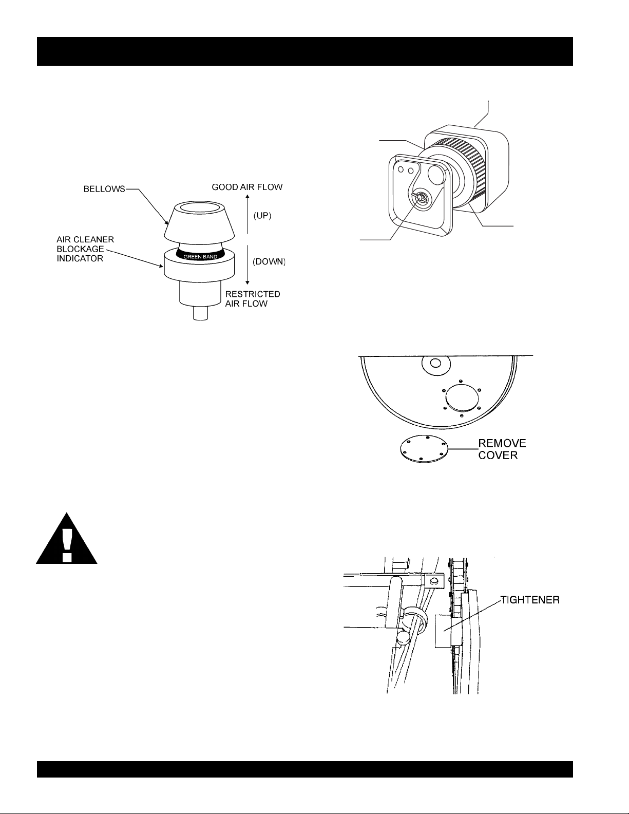
TESTING ENGINEAAIR FILTER BLOCKAGE INDICATOR
To test the air cleaner blockage indicator (Figure 28) run the
engine at full speed for a short time. If the rubber bellows is
pulled inwards (down), and the green rubber band cannot be
seen, this implies that maintenance work is required on the
CLEAN USING
COMPRESSED
DRY AIR
air cleaner. Clean or replace air cleaner.
WING NUT
CHECKING THE CHAINS
1. Take off the checking cover on roller and coat grease on the
chain if necessary (Figure 30). The chain should be lightly
Figure 28. Air Filter Blockage Indicator
lubricated with motor oil.
CLEANING OR CHANGING ENGINE AIR FILTER
AIR FILTER
CANNISTER
AIR FILTER
CARTRIDGE
Figure 29. Air Filter
If engine is operating in very dusty and dry grass conditions.
A clogged air filter will result in high fuel consumption, loss
of power and excessive carbon buildup in the combustion
chamber. Clean air filter daily. Remember if operating in dusty
conditions, check the rubber bellows on the air blockage
indicator several times a day.
CAUTION :
DO NOT blow high pressure, high velocity
compressed air thru the air filter cartridge. The
high velocity air will damage the filter, which
will then allow contaminates to pass into the
engine.
To clean or replace air filter loosen the wing nut on the air
filter housing (Figure 29), remove the cover and take out air
filter cartridge. If only cleaning of the air filter is desired blow
through the air filter cartridge from the inside, moving a jet
of dry compressed air up and down until all dust is removed.
2. Check the chain tension and if loose, adjust the chain tension
with the tightener (Figure 31). Chain tension should be
adjusted every 50 hours of operation.
Figure 30. Chain Cover
Figure 31. Chain Tightener
PAGE 26 — MQ-MIKASA MDR-9D VIBRATORY ROLLER — OPERATION AND PARTS MANUAL — REV. #0 (12/17/03)
Page 27
MDR-9D — MAINTENANCE
CAUTION:
NEVER attempt to check the V-belt with the
engine running. Severe injury can occur if your
hand gets caught between the V-belt and the
clutch (Figure 32). Always use safety gloves.
CLUTCH
PULLEY
VIBRATOR
PULLEY
Figure 32. V-Belt Hazard
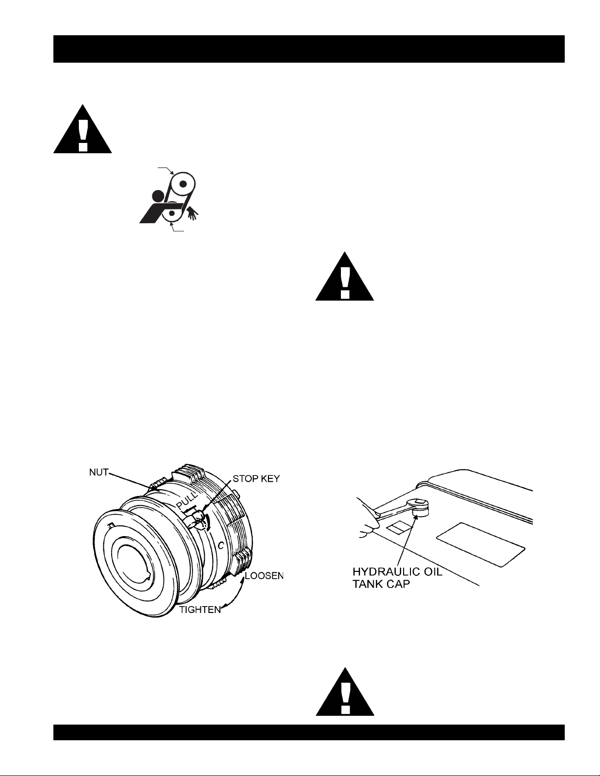
VIBRATION CLUTCH ADJUSTMENT
1. Remove the protective cover from the clutch by removing
the 4 allen screws.
2. Pull out the stop key and turn to the release position (Figure
33).
3. Viewing the clutch from the shifter-pulley side: if the clutch
nut is turned to the right, the clearance between the adjusting
and pressure plate decreases as the amount of torque
increases. Normal adjustment is from 1 to 2 notches.
4. Make sure that the shifting lever is not too stiff. Lever should
engage with moderate pressure.
5. After adjustment, return the stop key to the locked position.
HYDRAULIC OIL CHECK
1. Check for any oil leakage from the hoses and joints daily.
2. Check hydraulic oil level every 4 to 5 hours after starting
operation.
3. After one week of operation, check hydraulic level twice a
day .
4. After two weeks of operation, check hydraulic level once a
day .
5. Replace hydraulic oil after first 200 hours and in every 1,000
hours of operation.
CAUTION:
REPLACING HYDRAULIC OIL
1. Change the hydraulic oil every 1,000 to 1,500 hours of
operation. Change the hydraulic oil more often in high
ambient temperature operation.
2. Remove the drain plug and hose tank and drain the hydraulic
oil.
3. Reinstall the drain plug to the oil tank.
4. Open the tank cap (Figure 34) and fill tank with hydraulic oil.
(Capacity: About 4.5 gallons). Use
equivalent.
Make sure hydraulic oil is at a normal safe
operating level. DO NOT over fill.
Shell Tellus Oil #46
or
Figure 34. Hydraulic Oil Change
Figure 33. Clutch Adjustment
5. After filling tank, tighten the tank cap firmly with a wrench.
CAUTION:
Make sure that dust , water, and other foreign
objects do not enter tank. It is recommended to
filter the oil through a cloth.
MQ-MIKASA MDR-9D VIBRATORY ROLLER — OPERATION AND PARTS MANUAL — REV. #0 (12/17/03) — PAGE 27
Page 28
MDR-9D — MAINTENANCE
HYDRAULIC OIL FILTER CHECK
1. The hydraulic oil filter should be replaced after first 25 hours
of operation.
2. After first replacement, it should be replaced after 250 hours
operation (2 months), every 500 hours of operation (4
months), and every 1,000 hours of operation thereafter.
3. When the suction resistance exceeds 254mmHg (oil
temperature in operation is 140 degrees F), replace filter.
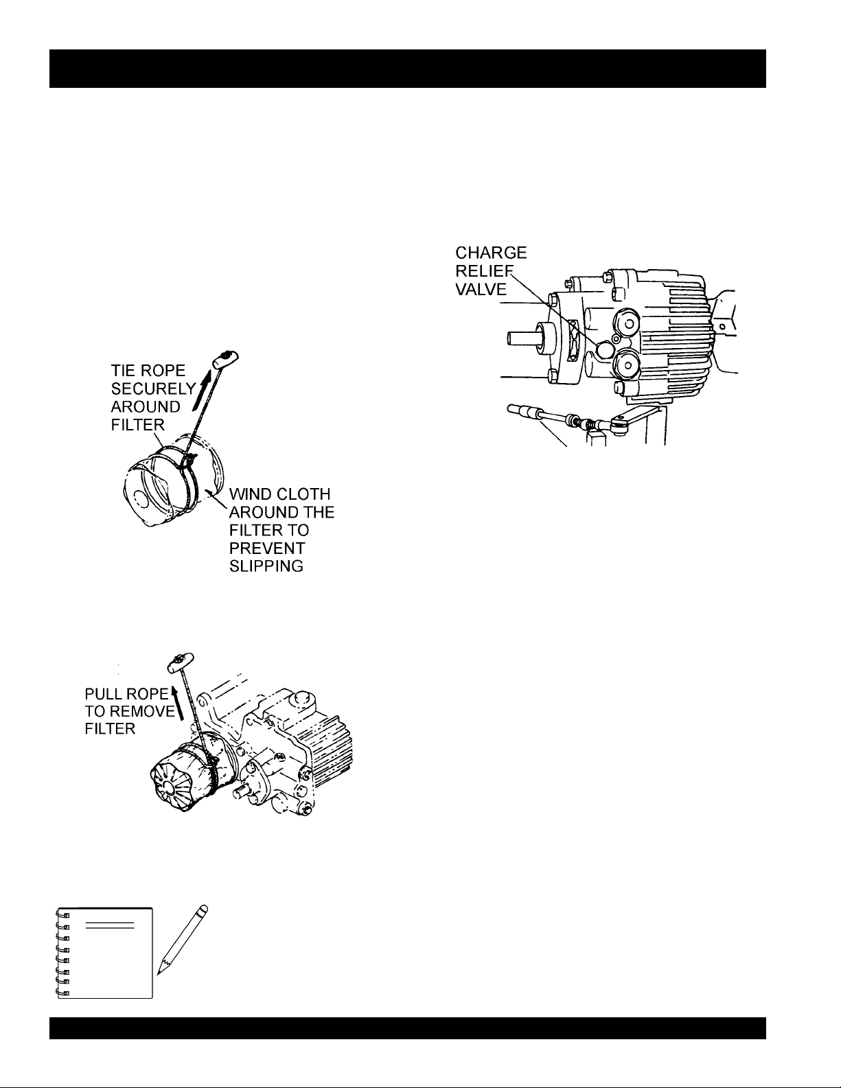
4. To remove the oil filter, wind a cloth around the filter to prevent
slipping (Figure 35).
5. Tie a rope securely around the filter (Figure 35).
HDRAULIC AIR EXTRACTION
1. After filling hydraulic oil tank with oil, loosen the oil hose
joint and check that oil is enough to reach the oil suction
and outlet ports in the hydraulic transmission. Tighten the
hose joint securely after checking.
2. Loosen the charge relief valve located on the front side of
the hydraulic transmission (Figure 37).
3. Check that oil flows out from the valve hole.
Figure 37. Loosening Charge Relief Valve
4. Replace the charge relief valve tightly.
5. With the travel and vibrator levers in neutral position, start
Figure 35. Cloth and Rope Around Filter
6. Forcibly pull the rope to remove the filter (Figure 36).
Figure 36. Filter Removal
7. Immediately replace with new filter, screwing it on by hand
to avoid hydraulic oil leak.
6. Check the forward and reverse rotation of the output shaft
7. Check the oil level gauge and make sure that there are no
8. When oil level in the tank is low, replenish oil up to the
9. If bubbles remain in the oil or foam is found, air is being
the engine and idle at low speed for 3 to 5 minutes.
by moving the travel lever slowly to its forward and reverse
positions.
air bubbles mixed in the oil. After checking, operate the roller
slowly at first then at full speed.
specified level, and screw the cap securely with a wrench.
sucked through the suction side and should be checked.
NOTE
PAGE 28 — MQ-MIKASA MDR-9D VIBRATORY ROLLER — OPERATION AND PARTS MANUAL — REV. #0 (12/17/03)
Use only genuine Mikasa
replacement oil filters (10
micron filter paper. Do not use
automobile-type oil filters.
Page 29
NEUTRAL POSITION ADJUSTMENT
Once the travel lever has veen set to neutral position with the
engine running, the hydraulic brake is is operating and the roller
should not move. If the roller inches forward or backwards with
the lever in the neutral position, turn-buckle of the cable should
be adjusted as follows:
1. Stop the engine and set the travel lever in the neutral
position.
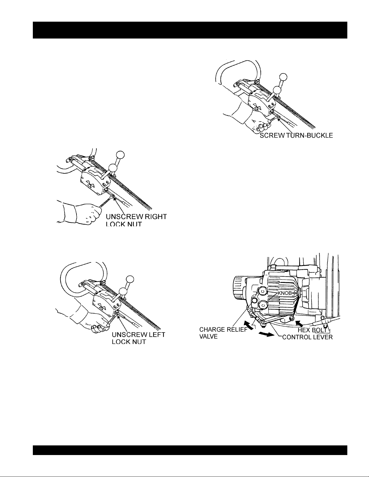
2. Unscrew the two lock nuts on the sides of the cable (Figures
38 and 39).
If the neutral position of the travel lever and the neutral point of
transmission do not match after adjusment is repeated, align as
follows:
1. Loosen the hex socket head bolt used for mounting the
control lever on the underside of the transmission (Figure
41).
MDR-9D — MAINTENANCE
Figure 40. Adjusting the Turn-Buckle
2. For forward movement, move the control lever slightly to the
left.
Figure 38. Unscrewing Right Lock Nut
Figure 39. Unscrewing Left Lock Nut
3. If the machine moves forward, screw the turn-buckle
clockwise. If the machine moves backwards, screw the turnbuckle counterclockwise (Figure 40).
3. for backwards movement, move the control lever slighty to
the right.
Figure 41. Unscrewing Left Lock Nut
4. Screw back the lock nuts on the turn-buckle.
5. Start the engine and make sure that the roller does not inch
forward or backward at the neutral position of the travel
lever.
MQ-MIKASA MDR-9D VIBRATORY ROLLER — OPERATION AND PARTS MANUAL — REV. #0 (12/17/03) — PAGE 29
Page 30

MDR-9D — TROUBLESHOOTING
Practically all breakdowns can be prevented by proper handling and maintenance inspections, but in the event of a breakdown,
please take a remedial action following the diagnosis based on the Engine and Roller Troubleshooting (Tables 8 and 9) information
shown below and on the proceeding page. If the problem cannot be remedied, please leave the unit just as it is and consult our
company's business office or service plant.
GNITOOHSELBUORTENIGNE.8ELBAT
MOTPMYSMELBORPELBISSOPNOITULOS
?noitisop"POTS"nisirevellortnocdeepS .noitisop"TRATS"otrevellortnocdeepsteS
?pmupnoitcejnignihcaerleufoN .metsysleuferitnekcehC.leufddA
?pmupleufevitcefeD.pmupleufecalpeR
?deggolcretlifleuF .knatnaelcdnaretlifleufecalpeR
sitratsrotratstonlliwenignE
ebnacenignehguohtla,deyaled
.revodenrut
lliwenigneserutarepmetwoltA
.tratston
sanoosspotstubserifenignE
.ffodehctiwssiretrats
gnirudflestiybspotsenignE
.noitarepolamron
?enilylppusleufytluaF .enilleufriaperroecalpeR
?wolootnoisserpmoC
?yltcerrocgnikrowtonrotcejnileuF
?wolooterusserpliO .erusserplioenignekcehC
?dedeecxetimilerutarepmetgnitratswoL
otecnatsiseretauqedanisahsetarapesleuF
?serutarepmetwol
?kcihtootlioenignE
?noitisopPOTSnirevelelttorhT .noitisopNURotrevelelttorhtnoitisopeR
?dekcolbretlifleuF.retlifleufecalpeR
?dekcolbylppusleuF .metsysleuferitneehtkcehC
?ytpmeknatleuF.leufddA
?dekcolbretlifleuF.retlifleufecalpeR
rotsujdA.sevlavdnarednilyc,notsipkcehC
.launamriaperenignerepriaper
htiwecnadroccanirotcejniecalperroriapeR
.launamriaperenigne
dnasnoitcurtsnignitratsdlochtiwylpmoC
.ytisocsivlioreporp
segremeleuf)dibrutton(raelcrehtehwkcehC
.)pmupnoitcejnimorfhcated(enilleufehtmorf
ehtpumraw,detarapesrodibrutsileufehtfI
ylppusleufetelpmocehtniardroenigne
.leufleseidedargretniwhtiwleufeR.metsys
liofoepyttcerrochtiwesacknarcenignellifeR
.tnemnorivneretniwrof
?ytpmeknatleuF.retlifleufecalpeR
?deggolcretlifleuF.retlifleufecalpeR
dnatuptuo,rewopenignewoL
.deeps
?noitisopdetceles
?llufootlevellioenignE.levellioenignetcerroC
?dekcolbretlifriA .retlifriaecalperronaelC
dnatuptuorewopenignewoL
.ekomstsuahxekcalb,deepswol
?rotcejnitanoitcnuflaM.launamenigneeeS
?etauqedanisignitnevknatleuF .detnevyletauqedasiknattahterusnE
niniamertonseodrevellortnocdeepS
?secnaraelcevlavtcerrocnI .noitacificepsenignerepsevlavtsujdA
.noitcaevitcerrocroflaunamenigneeeS
PAGE 30 — MQ-MIKASA MDR-9D VIBRATORY ROLLER — OPERATION AND PARTS MANUAL — REV. #0 (12/17/03)
Page 31

MDR-9D — TROUBLESHOOTING
)DEUNITNOC(GNITOOHSELBUORTENIGNE.8ELBAT
MOTPMYSMELBORPELBISSOPNOITULOS
?ytpmeknatleuF.retlifleufecalpeR
?deggolcretlifleuF.retlifleufecalpeR
dnatuptuo,rewopenignewoL
.deeps
?noitisop
?llufootlevellioenignE ?levellioenignetcerroC
?dekcolbretlifriA .retlifriaecalperronaelC
dnatuptuorewopenignewoL
.ekomstsuahxekcalb,deepswol
?rotcejnitanoitcnuflaM.launamenigneeeS
MOTPMYSMELBORPELBISSOPNOITULOS
rolevarttonseodtinU
.htoomstonsilevart
?etauqedanisignitnevknatleuF .detnevyletauqedasiknattahterusnE
detcelesniniamertonseodrevellortnocdeepS
?secnaraelcevlavtcerrocnI .noitacificepsenignerepsevlavtsujdA
?hctulclagufirtnecevitcefeD .hctulcecalperroriapeR
?egnalfdnagnilpuocrebburdegamaD .egnalfdnagnilpuocrebburecalpeR
?knildnaelbaclevartevitcefeD .knildnaelbaclevartecalperroriapeR
?reparcsnidumhcumootroreparcsdegamaD .reparcsriaperroecalpeR
?retlifliodeggolcrodegamaD.retlifecalpeR
?epipciluardyhgnikaelrodegamaD .strapecalperroriapeR
.noitcaevitcerrocroflaunamenigneeeS
GNITOOHSELBUORTRELLOR.9ELBAT
?liodetanimatnocrolevelliowoL .lioecalperrohsinelpeR
?noissimsnartciluardyhgnikaelrodegamaD .pmupciluardyhecalperroriapeR
?noissimsnartciluardyhgnikaelrodegamaD .rotomciluardyhecalperroriapeR
?gniraebdnaraegmurddegamaD.strapriapeR
?noitatormurddaB .murdecalperroriapeR
?hctulclagufirtnecevitcefeD .hctulcecalperroriapeR
?tleb-VgnippilsrodegamaD .noisnettsujdarotleb-VecalpeR
?egaknildnaelbacnoitarbivdegamaD
roetarbivtonseodtinU
.noitarbivkaewsah
?hctulcnoitarbivdegamaD .hctulcecalperrotsujdA
?tleb-VyelluprotarbivhctulcevitcefeD.tleb-VecalpeR
?dnahhtiwylhtoomsnruttonseodrotarbiV
.egaknil
.hgihylevissecxetonsilevel
dnaelbacnoitarbivriaperroecalpeR
liofikcehC.rotarbivriaperdnakcehC
MQ-MIKASA MDR-9D VIBRATORY ROLLER — OPERATION AND PARTS MANUAL — REV. #0 (12/17/03) — PAGE 31
Page 32

EXPLANATION OF CODE IN REMARKS COLUMN
How to read the marks and remarks used in this parts
book.
Items Found In the “Remarks” Column
Serial Numbers-Where indicated, this indicates a serial number
range (inclusive) where a particular part is used.
Model Number-Where indicated, this shows that the
corresponding part is utilized only with this specific model number
or model number variant.
Items Found In the “Items Number” Column
All parts with same symbol in the number column,
or <, belong to the same assembly or kit
, #, +, %,
*
The contents of this parts
NOTE
catalog are subject to
change without notice.
NOTE
If more than one of the same
reference number is listed,
the last one listed indicates
newest (or latest) part
available.
PAGE 32 — MQ-MIKASA MDR-9D VIBRATORY ROLLER — OPERATION AND PARTS MANUAL — REV. #0 (12/17/03)
Page 33

MQ MIKASA MDR-9D/MDR-9DES VIBRATORY WALKBEHIND ROLLER W/HATZ 1D81Z DIESEL ENGINE
1 to 3 Units
Qty. P/N Description
3 .......... 501010440 ........... OIL FILTER, TRANSMISSION
1 .......... 075080061 ........... CHAIN, DRIVE
6 .......... EM505834 ............ V-BELT
3 .......... 502303040 ........... THROTTLE WIRE
6 .......... 01480000 ............. OIL FILTER, ENGINE
6 .......... 50478800 ............. FUEL FILTER, ENGINE
6 .......... 01493000 ............. AIR FILTER, ENGINE
3 .......... 50345300 ............. KEY, IGNITION
SUGGESTED SPARE PARTS
MQ-MIKASA MDR-9D VIBRATORY ROLLER — OPERATION AND PARTS MANUAL — REV. #0 (12/17/03) — PAGE 33
Page 34

DECAL PLACEMENT
MDR-9D — DECAL PLACEMENT
PAGE 34 — MQ-MIKASA MDR-9D VIBRATORY ROLLER — OPERATION AND PARTS MANUAL — REV. #0 (12/17/03)
Page 35

MDR-9D — DECAL PLACEMENT
DECAL PLACEMENT
NO. PART NO. PART NAME QTY. REMARKS
1 920200591 PLATE, CAUTION 1
2 920200630 PLATE, SERIAL NO. 1
3 920201590 DECAL, MQ MARK 98X70 1
4 920101510 DECAL, MIKASA MARK 440MM 1
5 920203290 DECAL, CAUTION 1
6 920200450 DECAL, OIL FILTER 1
7 920101290 DECAL, VIBRATION 2
8 920201100 DECAL, CLUTCH LEVER 2
9 920200320 DECAL, WATER TANK 1
10 920200440 DECAL, PROHIBIT TOW 1
11 920200470 DECAL, OIL TANK 1
12 920101480 DECAL, OIL LEVEL 1
13 920101280 DECAL, FORWARD & REVERSE 1
14 920101200 DECAL, GREASE 1
MQ-MIKASA MDR-9D VIBRATORY ROLLER — OPERATION AND PARTS MANUAL — REV. #0 (12/17/03) — PAGE 35
Page 36

BODY ASSY.
MDR-9D — BODY ASSY.
PAGE 36 — MQ-MIKASA MDR-9D VIBRATORY ROLLER — OPERATION AND PARTS MANUAL — REV. #0 (12/17/03)
Page 37

MDR-9D — BODY ASSY.
BODY ASSY.
NO. PART NO. PART NAME QTY. REMARKS
1 502100600 BASE 1
2 502100720 SIDE PLATE, RIGHT 1
3 502100710 SIDE PLATE, LEFT 1
4 502200960 RUBBER PLATE 2
5 001211430 BOLT 14X30 H 8
6 030214350 WASHER, LOCK 8
8 930407021 SHOCK ABSORBER MED-70/MS 4
9 020312100 NUT 8
10 030212300 WASHER, LOCK 8
42 502201150 SPRINKLING PIPE, FRONT 1
43 502201160 SPRINKLING PIPE, REAR 1
44 502402930 VINYL PIPE 10X13X280 1
45 502402940 VINYL PIPE 10X13X950 1
46 001221025 BOLT 10X25 T 6
48 030210250 WASHER, LOCK 6
49 501010150 CAP 1/4 4
51 502302511 SCRAPER, END 2
52 001221030 BOLT 10X30 T 8
53 030210250 WASHER, LOCK 8
54 502424050 SCRAPER/CENTER 2
55 001220825 BOLT 8X25 T 6
56 030208200 WASHER, LOCK 6
57 952401560 WASHER 8.5X20X3 6
58 031110160 WASHER, FLAT 8
59 502200990 BASE, SCRAPER 1
60 001521225 SOCKET HEAD BOLT 12X25 T 18
68 502403940 CHAIN COVER 2
69 001521020 SOCKET HEAD BOLT 10X20 T 4
82 020310080 NUT 4
83 030210250 WASHER, LOCK 4
MQ-MIKASA MDR-9D VIBRATORY ROLLER — OPERATION AND PARTS MANUAL — REV. #0 (12/17/03) — PAGE 37
Page 38

FRONT COVER ASSY.
MDR-9D — FRONT COVER ASSY.
PAGE 38 — MQ-MIKASA MDR-9D VIBRATORY ROLLER — OPERATION AND PARTS MANUAL — REV. #0 (12/17/03)
Page 39

MDR-9D — FRONT COVER ASSY.
FRONT COVER ASSY.
NO. PART NO. PART NAME QTY. REMARKS
13 031110160 WASHER, FLAT 4
14 502103800 FRONT COVER 1
16 001220820 BOLT 8X20 T 4
17 030208200 WASHER, LOCK 7
18 952401560 WASHER 8.5X20X3 7
20 502302490 CHECK COVER 1
21 001220815 BOLT 8X15 T 4
22 030208200 WASHER, LOCK 4
23 031108160 WASHER, FLAT 4
24 502302500 SUPPORT/COVER 1
25 001221020 BOLT 10X20 T 1
26 030210250 WASHER, LOCK 1
27 021110160 WASHER, FLAT 1
28 001220825 BOLT 8X25 T 3
30 502201830 BELT COVER 1
32 001221020 BOLT 10X20 T 2
33 030210250 WASHER, LOCK 2
34 031110160 WASHER, FLAT 2
35 001221015 BOLT 10X15 T 2
36 030210250 WASHER, LOCK 2
37 031110160 WASHER, FLAT 2
38 502010650 ELBOW 90 DEG. 1/4 2
39 407310670 TANK CAP D108-120, RUBBER 1
41 954403241 COCK PT 1/4, BH-1211 (AL) 2
65 001801050 BOLT 10X50 WHOLE THREAD 1
66 020310080 NUT
81 001211030 BOLT 10X30 H 4
82 020310080 NUT 4
83 030210250 WASHER, LOCK 4
84 502405920 PLATE, COVER SETTING 1
85 001221020 BOLT 10X20 T 2
86 030210250 WASHER, LOCK M10 2
87 031110160 WASHER, FLAT M10 2
100 959402990 ROPE 1
101 091005020 SCREW 5X20 1
102 020305040 NUT 1
103 030205130 WASHER, LOCK 1
104 031105080 WASHER, FLAT 2
105 025203020 SPLIT COTTER PIN 3X20 1
106 959403251 PLATE SPRING 2
107 502420150 SPACER 1
108 001200820 BOLT 8X20 2
109 030208200 WASHER, LOCK 2
110 031108160 WASHER, FLAT 2
MQ-MIKASA MDR-9D VIBRATORY ROLLER — OPERATION AND PARTS MANUAL — REV. #0 (12/17/03) — PAGE 39
Page 40

AXLE ASSY.
MDR-9D — AXLE ASSY.
PAGE 40 — MQ-MIKASA MDR-9D VIBRATORY ROLLER — OPERATION AND PARTS MANUAL — REV. #0 (12/17/03)
Page 41

MDR-9D — AXLE ASSY.
AXLE ASSY.
NO. PART NO. PART NAME QTY. REMARKS
1 502101570 DRUM 2
2 502202290 ROLLER SHAFT 2
3 044006309 BEARING 6309VV 4
4 952400940 SPACER 45605 4
5 502302420 BEARING COVER 2
6 060406010 OIL SEAL TC-689012 4
7 001521025 SOCKET HEAD BOLT 10X25 T 12
8 502200930 BRACKET/L 2
9 502302430 SPACER 2
10 001521240 SOCKET HEAD BOLT 12X40 T 12
11 502200940 BRACKET/R FRONT 1
12 502200950 BRACKET/R REAR 1
13 020130240 NUT M30, P2.0 4
14 030230750 WASHER, LOCK M30 4
15 502302440 GEAR 57 2
16 001521040 SOCKET HEAD BOLT 10X40 T 12
17 502303370 GEAR SHAFT 2
17 502338050 GEAR SHAFT 2
18 044006370 BEARING 6307VV 2
19 047910050 ROLLER BEARING NF307W 2
20 952401240 SPACER 35453 2
20 952406190 SPACER 35X45X3 S 2
22 502302460 COVER/GEAR SHAFT 2
23 060305010 OIL SEAL TB-55729 2
24 001520820 SOCKET HEAD BOLT 8X20 T 8
25 502402720 SPROCKET 15 2
26 951400090 KEY 10X8X33 2
27 020118150 NUT M18, P1.5 2
28 030218460 WASHER, LOCK M18 2
29 952400950 WASHER 19456 2
30 502305360 BLOCK 2
31 502303590 CYLINDER BLOCK 2
32 001521235 SOCKET HEAD BOLT 12X35 T 30
33 001521240 SOCKET HEAD BOLT 12X40 T 30
34 502402740 BRACKET COVER 2
35 001210820 BOLT 8X20 H 12
36 030208200 WASHER, LOCK 12
37 502403090 BEARING HOLDER 2
38 075080061 CHAIN RS80-61 1
39 502402920 TIGHTENER 1
MQ-MIKASA MDR-9D VIBRATORY ROLLER — OPERATION AND PARTS MANUAL — REV. #0 (12/17/03) — PAGE 41
Page 42

AXLE ASSY.
MDR-9D — AXLE ASSY. (CONTINUED)
PAGE 42 — MQ-MIKASA MDR-9D VIBRATORY ROLLER — OPERATION AND PARTS MANUAL — REV. #0 (12/17/03)
Page 43

MDR-9D — AXLE ASSY. (CONTINUED)
AXLE ASSY.
NO. PART NO. PART NAME QTY. REMARKS
40 502302480 TIGHTENER PLATE (SHAFT) 1
41 044006205 BEARING 6205VV 2
42 080100520 STOP RING R-52 1
43 001210820 BOLT 8X20 H 1
44 030208200 WASHER, LOCK 1
45 952400130 WASHER 9304 1
46 502402750 TIGHTENER PLATE HOLDER 1
47 001521230 SOCKET HEAD BOLT 12X30 T 3
48 502402760 FELT SEAL 6X8X1350 2
49 502402770 FELT SEAL 6X8X188 2
50 502402780 FELT SEAL 5X6X217 2
51 952401330 COLLAR 72803 2
52 060604030 OIL SEAL VC-45686 2
54 042006309 BEARING 6309ZZ 4
55 502408150 FELT RING 901027 4
61 351010050 GREASE FITTING A-MT6X1 2
MQ-MIKASA MDR-9D VIBRATORY ROLLER — OPERATION AND PARTS MANUAL — REV. #0 (12/17/03) — PAGE 43
Page 44

TRANSMISSION ASSY.
MDR-9D — TRANSMISSION ASSY.
PAGE 44 — MQ-MIKASA MDR-9D VIBRATORY ROLLER — OPERATION AND PARTS MANUAL — REV. #0 (12/17/03)
Page 45

MDR-9D — TRANSMISSION ASSY.
TRANSMISSION ASSY.
NO. PART NO. PART NAME QTY. REMARKS
1 502010530 GEAR CASE 1
2 502010540 COVER, GEAR CASE 1
3 501010410 PACKING, GEAR CASE COVER 1
4 001520620 SOCKET HEAD BOLT 6X20 T 6
5 031106100 WASHER, FLAT M6 6
6 501010420 SET BOLT, 87L-M12-/HST 4
7 501010430 TRANSMISSION 1515-522 1
8 501010440 OIL FILTER 1
9 501010450 PACKING/TRANSMISSION 1
11 030210250 WASHER, LOCK 4
12 020310080 NUT 4
14 501010460 PINION 15 1
15 951400100 KEY 5X5X35 1
16 952400130 WASHER 9304 1
17 001210820 BOLT 8X20 H 1
18 030208200 WASHER, LOCK 1
19 502303350 GEAR 80 1
20 502010570 DRIVE SHAFT 1
21 501010500 SPROKET 9 1
22 951400110 KEY 7X7X35 2
23 952400170 WASHER 19454 2
24 020118150 NUT M18, P1.5 2
25 030218460 WASHER, LOCK M18 2
26 042006207 BEARING 6207ZZ 1
27 042006306 BEARING 6306ZZ 1
28 080200350 STOP RING S-35 1
29 060303030 OIL SEAL TB-30428 1
30 501010520 BEARING COVER 1
31 001220825 BOLT 8X25 T 4
32 030208200 WASHER, LOCK 4
33 001211025 BOLT 10X25 H 4
34 030210250 WASHER, LOCK 4
36 502302530 FLANGE FAN 1
37 080100160 STOP RING R-16 1
38 502010590 KEY 5X5X22/4DK 1
39 502321570 RUBBER COUPLING 1
40 515447020 COUPLING PIN 6
41 099208012 SOCKET HEAD SCREW 8X12 T 2
63 502402800 LEVER 1
64 001521025 SOCKET HEAD BOLT 10X25 T 1
MQ-MIKASA MDR-9D VIBRATORY ROLLER — OPERATION AND PARTS MANUAL — REV. #0 (12/17/03) — PAGE 45
Page 46

HYDRAULIC OIL TANK ASSY.
MDR-9D — HYDRAULIC OIL TANK ASSY.
PAGE 46 — MQ-MIKASA MDR-9D VIBRATORY ROLLER — OPERATION AND PARTS MANUAL — REV. #0 (12/17/03)
Page 47

MDR-9D — HYDRAULIC OIL TANK ASSY.
HYDRAULIC OIL TANK ASSY.
NO. PART NO. PART NAME QTY. REMARKS
44 050200160 O-RING P-16 1
45 501010720 JOINT 3/4-16 1
46 501010590 JOINT 3/8 1
47 501010600 JOINT 1/4 1
48 502302850 OIL HOSE 3/8 320L 1
49 502302840 OIL HOSE 1/4 320L 1
50 502201000 OIL TANK 1
51 502010640 ELBOW 90 DEG. 3/8 1
52 502010650 ELBOW 90 DEG. 1/4 1
53 953405270 PLUG 1/4X14 13L 1
54 953405260 PACKING 1/4 (CU) 1
55 953405840 DRAIN PLUG M18 (H) 1
56 953400020 PACKING 19302 1
57 001221035 BOLT 10X35 T 4
58 030210250 WASHER, LOCK 4
59 031110160 WASHER, FLAT 4
60 959010110 LEVEL GAUGE/SP-1 W/P 1
61 952401960 COLLAR 11X30X16 1
MQ-MIKASA MDR-9D VIBRATORY ROLLER — OPERATION AND PARTS MANUAL — REV. #0 (12/17/03) — PAGE 47
Page 48

CLUTCH BOX ASSY.
MDR-9D — CLUTCH BOX ASSY.
PAGE 48 — MQ-MIKASA MDR-9D VIBRATORY ROLLER — OPERATION AND PARTS MANUAL — REV. #0 (12/17/03)
Page 49

MDR-9D — CLUTCH BOX ASSY.
CLUTCH BOX ASSY.
NO. PART NO. PART NAME QTY. REMARKS
1 502302610 CLUTCH PULLEY/IN 1
2
*
3
*
4
*
5
*
6
*
7
*
8
*
9
*
10
10
10
10
11
12
13
14
15
16
17
18
19
20
21
22 501010890 PACKING, CLUTCH CASE 1
23
24
25
26 502302640 CLUTCH PULLEY/OUT 1
27 951400070 KEY 7X7X26 2
28 952400140 WASHER 13304 2
29 030212300 WASHER, LOCK M12 2
30 020312100 NUT 2
31 001221035 BOLT 10X35 T 4
32 030210250 WASHER, LOCK 4
33 952401860 WASHER 112545 4
34 953400270 PLUG 1/4X14 10L 2
34 953405270 PLUG 1/4X14 13L 2
502302620 CLUTCH SHAFT/IN 1
502302630 CLUTCH SHAFT/OUT 1
040006205 BEARING 6205 5
040006202 BEARING 6202 1
501010800 CLUTCH SL1.2-20/OS225 1
080200250 STOP RING S-25 1
951400060 KEY 5X5X58 1
501010810 COLLAR 25322/BEARING 3
501010822 SPACER 0.8T/CLUTCH AR
*
501010823 SPACER 1.0T/CLUTCH AR
*
501010824 SPACER 2.3T/CLUTCH AR
*
501010825 SPACER 3.2T/CLUTCH AR
*
501010830 CLUTCH CASE 1
*
502910010 CLUTCH BOX ASSY. ................................... 1 ...... INCLUDES ITEMS W/
*
501010830 PACKING/BEARING HOLDER 2
*
060102010 OIL SEAL SB-25388 2
*
001520620 SOCKET HEAD BOLT 6X20 T 8
*
501010850 SHIFTER FORK 1
*
501010860 FORK BLOCK 2
*
001520625 SOCKET HEAD BOLT 6X25 T 2
*
501010870 SHIFTER SHAFT 1
*
050200110 O-RING P-11 2
*
501301160 COVER, CLUTCH CASE 1
*
001520625 SOCKET HEAD BOLT 6X25 T 4
*
501010900 PLUG 3/4 1
*
501010910 PACKING 3/4 1
*
*
MQ-MIKASA MDR-9D VIBRATORY ROLLER — OPERATION AND PARTS MANUAL — REV. #0 (12/17/03) — PAGE 49
Page 50

CLUTCH BOX ASSY.
MDR-9D — CLUTCH BOX ASSY. (CONTINUED)
PAGE 50 — MQ-MIKASA MDR-9D VIBRATORY ROLLER — OPERATION AND PARTS MANUAL — REV. #0 (12/17/03)
Page 51

MDR-9D — CLUTCH BOX ASSY. (CONTINUED)
CLUTCH BOX ASSY.
NO. PART NO. PART NAME QTY. REMARKS
35
36
37
38
39
40
42
43# 501402400 TIGHTENER PULLEY 1
44# 501302160 TIGHTENER SUPPORT 1
45# 042006204 BEARING 6204ZZ 2
46# 952400930 COLLAR 20252 1
47# 080100470 STOP RING R-47 1
48# 952400130 WASHER 9304 1
49# 001200820 BOLT 8X20 1
50# 030208200 WASHER, LOCK 1
51# 001221035 BOLT 10X35 T 2
52# 030210250 WASHER, LOCK 2
53# 031110160 WASHER, FLAT 2
55 501910040 BELT TIGHTENER ASSY. ............................ 1 ...... INCLUDES ITEMS W/#
953405260 PACKING 1/4 (CU) 2
*
502302650 CLUTCH LEVER 1
*
959402980 BALL GRIP 40D-M12 1
*
001521025 SOCKET HEAD BOLT 10X25 T 1
*
501010950 BEARING HOLDER 1
*
502302660 BEARING HOLDER/INPUT SIDE 1
*
501402260 SET BOLT, L50M12/CLUTCH 4
*
MQ-MIKASA MDR-9D VIBRATORY ROLLER — OPERATION AND PARTS MANUAL — REV. #0 (12/17/03) — PAGE 51
Page 52

VIBRATION CASE ASSY.
MDR-9D — VIBRATION CASE ASSY.
PAGE 52 — MQ-MIKASA MDR-9D VIBRATORY ROLLER — OPERATION AND PARTS MANUAL — REV. #0 (12/17/03)
Page 53

MDR-9D — VIBRATION CASE ASSY.
VIBRATION CASE ASSY.
NO. PART NO. PART NAME QTY. REMARKS
1 502302570 VIBRATING PULLEY 1
2 502201010 ROTARY SHAFT/L 1
3 502201020 ROTARY SHAFT/R 1
4-1 502302582 GEAR (DRIVE-1P) 1
4-2 502302581 GEAR 44 (DRIVEN-2P) 1
5 951400081 KEY 10X8X17 2
6 951400090 KEY 10X8X33 1
7 952400900 WASHER 13446 3
8 001211235 BOLT 12X35 H 3
9 030212300 WASHER, LOCK M12 3
10 502302590 ECCENTRIC ROTATOR 2
11 001521040 SOCKET HEAD BOLT 10X40 T 8
12 040006309 BEARING 6309 4
13 080101000 STOP RING R-100 2
14 080200450 STOP RING S-45 4
15 060106010 OIL SEAL SB-659013 1
15 060206020 OIL SEAL SC-659013 1
16 952400911 SPACER 801003 1
17 502100650 VIBRATING CASE 1
18 502302600 CASE COVER 1
20 001521025 SOCKET HEAD BOLT 10X25 T 8
21 502201030 GEAR COVER 1
23 953400270 PLUG 1/4X14 10L 2
23 953405270 PLUG 1/4X14 13L 2
24 953405260 PACKING 1/4 (CU) 2
25 001520652 SOCKET HEAD BOLT 6X60 T 8
26 031106100 WASHER, FLAT M6 8
27 001221445 BOLT 14X45 T 14
28 030214350 WASHER, LOCK M14 14
29 502403140 T-JOINT 1
30 502010860 NIPPLE PT1/4 1
31 070100360 V-BELT A-36 2
32 502402300 BREATHER 1
33 953405260 PACKING 1/4 (CU) 1
34 502303010 PACKING, VIBRATION CASE/A 1
35 502303020 PACKING, VIBRATION CASE/B 1
36 502305480 ECCENTRIC ROTATOR 2
MQ-MIKASA MDR-9D VIBRATORY ROLLER — OPERATION AND PARTS MANUAL — REV. #0 (12/17/03) — PAGE 53
Page 54

UPPER CONTROL HANDLE ASSY.
MDR-9D — UPPER CONTROL HANDLE ASSY.
PAGE 54 — MQ-MIKASA MDR-9D VIBRATORY ROLLER — OPERATION AND PARTS MANUAL — REV. #0 (12/17/03)
Page 55

MDR-9D — UPPER CONTROL HANDLE ASSY.
UPPER CONTROL HANDLE ASSY.
NO. PART NO. PART NAME QTY. REMARKS
1 502101480 BAR HANDLE, D.C./9D 1
13 501011090 TRAVELING LEVER 1
14 501011100 LINK 1
15 959402980 BALL GRIP 40D-M12 2
16 001520620 SOCKET HEAD BOLT 6X20 T 1
17 030206150 WASHER, LOCK M6 15
18 031106100 WASHER, FLAT M6 6
19 501011110 STEEL BALL 1
20 501011120 SPRING, 1.2X8X34 1
21 505422750 GUIDE 1
22 001520615 SOCKET HEAD BOLT 6X15 T 2
23 501011140 BUSH 8918, LINK 1
24 501011150 CONICAL SPRING WASHER 1
25 001200835 BOLT 8X35 1
26 020308060 NUT 1
27 031108160 WASHER, FLAT 1
29 501011162 ROD END PR6-209 3
30 502314420 CABLE ASSY./C2110 1
31 501011180 CLAMP HC-40 4
32 501203980 HANDLE, D.C. 1
34 001210615 BOLT 6X15 H 4
39 001210620 BOLT 6X20 H 2
40 501202200 LEVER COVER, D.C. 1
41 501011220 LEVER GUIDE 1
42 001520652 SOCKET HEAD BOLT 6X60 T 3
43 001210615 BOLT 6X15 H 4
44 031106100 WASHER, FLAT M6 4
48 501011310 VIBRATING LEVER 1
49 050200160 O-RING P-16 1
50 020312100 NUT 1
51 030212300 WASHER, LOCK M12 1
52 031112230 WASHER, FLAT M12 1
53 502314410 CABLE ASSY./C2550 1
60 001220615 BOLT 6X25 T 4
MQ-MIKASA MDR-9D VIBRATORY ROLLER — OPERATION AND PARTS MANUAL — REV. #0 (12/17/03) — PAGE 55
Page 56

MDR-9D — UPPER CONTROL HANDLE ASSY. (CONTINUED)
UPPER CONTROL HANDLE ASSY.
PAGE 56 — MQ-MIKASA MDR-9D VIBRATORY ROLLER — OPERATION AND PARTS MANUAL — REV. #0 (12/17/03)
Page 57

MDR-9D — UPPER CONTROL HANDLE ASSY. (CONTINUED)
UPPER CONTROL HANDLE ASSY.
NO. PART NO. PART NAME QTY. REMARKS
61 025202020 SPLIT COTTER PIN 2X20 1
62 502010930 CLEVIS 1
63 502010940 CLEVIS PIN 1
97 501413650 TURN BUCKLE 1
98 501413660 ADJUST BOLT 1
99 020306050 NUT M6 1
100 022910090 NUT M6 (L) 1
101 501407790 HANDLE PIN, D.C. 1
102 501305190 ROD, D.C. 1
103 502416960 ROD-GUIDE 1
104 001520815 SOCKET HEAD BOLT 8X15 T 2
105 501407810 ROD SPRING, D.C. 1
106 501407820 NUT, D.C. 1
107 501416950 LINK, D.C. 1
108 099206008 SOCKET HEAD SCREW 6X8 T 1
109 501407840 LINK PIN, D.C., 6X28-23 1
110 031106100 WASHER, FLAT M6 2
111 025202012 SPLIT COTTER PIN 2X12 2
112 501416970 LEVER, D.C. 1
113 001200830 BOLT 8X30 1
114 501407880 GUIDE ROLLER, D.C. 1
115 020308060 NUT 1
116 501407890 LEVER SPRING, D.C. 1
117 031108160 WASHER, FLAT 1
118 001220815 BOLT 8X15 T 1
119 502910020 HANDLE STOPPER 1
MQ-MIKASA MDR-9D VIBRATORY ROLLER — OPERATION AND PARTS MANUAL — REV. #0 (12/17/03) — PAGE 57
Page 58

LOWER CONTROL HANDLE ASSY.
MDR-9D — LOWER CONTROL HANDLE ASSY.
PAGE 58 — MQ-MIKASA MDR-9D VIBRATORY ROLLER — OPERATION AND PARTS MANUAL — REV. #0 (12/17/03)
Page 59

MDR-9D — LOWER CONTROL HANDLE ASSY.
LOWER CONTROL HANDLE ASSY.
NO. PART NO. PART NAME QTY. REMARKS
2 501302670 HANDLE BRACKET, RIGHT 1
3 501302680 HANDLE BRACKET, LEFT 1
4 501402860 BOLT 20X170 1
5 001221245 BOLT 12X45 T 4
6 020312100 NUT M12 4
7 030212300 WASHER, LOCK M12 4
8 031112230 WASHER, FLAT M12 4
9 501402870 HANDLE STOPPER 1
10 501402880 SPRING/HANDLE (1.4X18X44) 1
11 020310080 NUT 1
12 959010413 EYE NUT 1
28 020120160 NUT M20, P1.5 2
29 501011162 ROD END PR6-209 3
30 502314420 CABLE ASSY./C2110 1
31 501011180 CLAMP HC-40 4
34 001210615 BOLT 6X15 H 4
36 502402900 CABLE STOPPER 1
37 001221020 BOLT 10X20 T 1
38 030210250 WASHER, LOCK 1
39 001210620 BOLT 6X20 H 2
45 0830000010 COIL SPRING 1
46 020306050 NUT M6 4
47 031106100 WASHER, FLAT M6 2
56 502402890 CABLE STOPPER 1
57 001220820 BOLT 8X20 T 2
58 030208200 WASHER, LOCK 2
59 031108160 WASHER, FLAT 2
60 0012-20615 BOLT 6x15 T 4
64 351010050 GREASE FITTING A-MT6X1 1
76 001220620 BOLT 6X20 T 1
MQ-MIKASA MDR-9D VIBRATORY ROLLER — OPERATION AND PARTS MANUAL — REV. #0 (12/17/03) — PAGE 59
Page 60

BATTERY ASSY.
MDR-9D — BATTERY ASSY.
PAGE 60 — MQ-MIKASA MDR-9D VIBRATORY ROLLER — OPERATION AND PARTS MANUAL — REV. #0 (12/17/03)
Page 61

MDR-9D — BATTERY ASSY.
BATTERY ASSY.
NO. PART NO. PART NAME QTY. REMARKS
70 502215490 BATTERY BASE 1
71 001200815 BOLT 8X15 4
72 030208200 SW M8 4
73 502403310 BATTERY PROTECT 1
74 502403320 BOLT/BATTERY 2
75 020308060 NUT M8 4
76 030208200 WASHER, LOCK M8 2
77 031108160 WASHER, FLAT M8 2
78 607010030 BATTERY 12N24-3.26A19L 1
79 502301040 BATTERY CORD (+) 220 1
80 502301050 BATTERY CORD (-) 380 1
MQ-MIKASA MDR-9D VIBRATORY ROLLER — OPERATION AND PARTS MANUAL — REV. #0 (12/17/03) — PAGE 61
Page 62

CRANKCASE ASSY.
HATZ 1D81Z ENGINE — CRANKCASE ASSY.
LETTERS IN BOLD INDICATE TYPE OF BONDING ADHESIVE TO BE USED.
D= LOCTITE 221 H= SILICON E= LOCTITE 648
PAGE 62 — MQ-MIKASA MDR-9D VIBRATORY ROLLER — OPERATION AND PARTS MANUAL — REV. #0 (12/17/03)
Page 63

HATZ 1D81Z ENGINE — CRANKCASE ASSY.
CRANKCASE ASSY.
NO. PART NO. PART NAME QTY. REMARKS
1 01249051 CRANKCASE ...................................... 1 ........INCLUDES ITEMS W/
3
*
4
*
5
*
6
*
7
*
8 04033700 MAIN BEARING -O.5 1
9
*
10
11
12
13
14
15
16
17 04011650 THRUST PLATE 1
18 04069500 SHIM 1.05 0..4
19 04062010 HEX SCREW M 9 X 28 4
22
23
25 04084500 SEALING RING 2
26 04084500 SEALING RING 2
50249101 CYL. PIN 6/20 4
03793900 NOZZLE 1
03793800 BEARING BUSH 1
03794000 PLUG 1..2
03793700 MAIN BEARING 1
04000800 PLUG 1
50144300 STUD M 6X16 2
*
03794510 STUD 1
*
03794800 INTERMEDIATE PIECE 1
*
50098300 STUD 8 X 20 2
*
50325500 COVER 10 1
*
50037800 STUD M 8 X 22 8
*
50328200 STUD M 16 X 22 2
*
50357700 GRUB SCREW M 8 X 10 1
*
04087400 STUD M 6 X 22 1
*
*
MQ-MIKASA MDR-9D VIBRATORY ROLLER — OPERATION AND PARTS MANUAL — REV. #0 (12/17/03) — PAGE 63
Page 64

HATZ 1D81Z ENGINE — CRANKCASE ASSY. (EXTERNAL PARTS)
CRANKCASE ASSY.(EXTERNAL PARTS)
LETTERS IN BOLD INDICATE TYPE OF BONDING ADHESIVE TO BE USED.
D= LOCTITE 221 H= SILICON E= LOCTITE 648
PAGE 64 — MQ-MIKASA MDR-9D VIBRATORY ROLLER — OPERATION AND PARTS MANUAL — REV. #0 (12/17/03)
Page 65

HATZ 1D81Z ENGINE — CRANKCASE ASSY. (EXTERNAL PARTS)
CRANKCASE ASSY.(EXTERNAL PARTS)
NO. PART NO. PART NAME QTY. REMARKS
1 03794100 WASHER 2
2 03794300 CAM FOLLOWER 2
3 93794201 CAM FOLLOW SPINDLE 2
4 50051000 ALLEN SCREW M 6 X 30 2
5 03795800 O-RING 12 X 18, 3 X 7.3 2
6 50329000 O-RING 9.5 X 2.5 3
7 03795100 O-RING 265 X 269, 4 X 3.6 1
8 01248810 PLATE 1
10 50417600 ALL. SCREW. M 8 X 25 Z4 22
11 03794900 HOUSING 1
12 03795000 SUCTION SIEVE 1
13 50327100 ALLEN SCREW M 6 X 50 2
14 01241700 OIL SUMP 1
15 50170900 WASHER, LOCK 6 12
16 50329100 ALLEN SCREW M 6 X 10 12
17 50001600 JOINT A22X27 2
18 50373100 DRAIN PLUG M 22 X 1.5 0..2
18 50140400 DRAIN PLUG 0..2
20 03794700 COVER 1
21 50328300 HEXAGON NUT M6 3
22 01321200 CLOS. SCREW + SIEVE 1
23 50286400 JOINT A 24 X 29 1
24 01321100 OIL RELIEF VALVE ASSY. ................... 1 ........INCLUDES ITEMS W/#
25# OIL RELIEF VALVE .............................. 1 ........CANNOT BE PURCHASED SEPARATELY
26# 50412900 O-RING 18 X 2 1
27 50062400 JOINT A10 X 13.5 2
28 50062300 CLOSING SCREW X 1 2
29 01241500 DIPSTICK ASSY .................................. 1 ........ INCLUDES ITEMS W/
30
*
31
32 50329200 O-RING 50X55X3 2
33 05068800 LUB. OIL FILT. HOUS. 1
34 50081200 WASHER, LOCK A6 4
35 50170600 ALLEN SCREW M 6 X 20 4
36 01480000 SUPRA OIL FILTER 1
37 01248900 COVER 1
38 04033401 COVER 1
39 04053210 SET SCREW M9 1
41 04024220 CAM FOLLOWER BRACK. 1
42 04062110 BOLT 1
43 04024301 CAM FOLLOWER T/U 1
44 50170800 ALLEN SCREW M 6 X 25 1
45 04045800 OIL SUMP 1
46 04046300 DRAIN EXTENSION 1
47 50001400 JOINT A 18 X 22 1
48 50044200 CLOS. SCREW M 18 X 1.5 1
49 50434300 STUD M 8 X 18 2
50 50050700 ALLEN SCREW M 6 X 16 8
52 50140400 DRAIN PLUG 1
53 04069500 SHIM 1.05 0..3
53 04069600 SHIM 1.2 0..3
54 04069800 SHIM 1.05 0..1
54 04069900 SHIM 1.20 0..1
55 04065400 CYLINDER HEAD BOLT 1
56 04084000 LIFTING SPRING 1
58 50139200 STUD M 6 X 16 2
59 05068900 GASKET 1
50359700 O-RING 20.29 X 2.62 2
*
DIPSTICK ............................................ 1 ........ CANNOT BE PURCHASED SEPARATELY
*
MQ-MIKASA MDR-9D VIBRATORY ROLLER — OPERATION AND PARTS MANUAL — REV. #0 (12/17/03) — PAGE 65
Page 66

CRANKSHAFT ASSY.
HATZ 1D81Z ENGINE — CRANKSHAFT ASSY.
LETTERS IN BOLD INDICATE TYPE OF BONDING ADHESIVE TO BE USED.
D= LOCTITE 221 H= SILICON E= LOCTITE 648
PAGE 66 — MQ-MIKASA MDR-9D VIBRATORY ROLLER — OPERATION AND PARTS MANUAL — REV. #0 (12/17/03)
Page 67

HATZ 1D81Z ENGINE — CRANKSHAFT ASSY.
CRANKSHAFT ASSY.
NO. PART NO. PART NAME QTY. REMARKS
1 01269810 CRANKSHAFT ASSY. ................................ 1 ...... INCLUDES ITEMS W/
2
*
3
*
4 03796000 COUNTER WEIGHT 1
5 50055000 ALLEN SCREW M 10 X 50 2
6
*
7 03796120 GEARWHEEL F. CRANKS 1
8 04000600 BUFFER RING 1
9 50224900 O-RING 123 X 2.5 1
10 01292100 BEARING FLANGE ASSY. ........................... 1 ...... INCLUDES ITEMS W/#
11# BEARING FLANGE ...................................... 1 ...... CANNOT BE PURCHASED SEPARATELY
12# 04006800 MAIN BEARING
13 04036100 MAIN BEARING -0.5 1
14# 50362700 OIL SEAL 62 X 90 X 10 1
15 50413600 WASHER 8
16 50364300 HEXAGON NUT 8
17 04023110 STUBSHAFT SAE W/KEY 1
18 01485500 STUBSHAFT SAE TAPER 1
19 04022910 STUBSHAFT ITALIA 1
20 05033200 STUBSHAFT ITALIA 23 1
21 03962700 FITTING KEY A6.35 X 63 1
22 50017800 WOODRUFF KEY 4 X 6.5 1
23 50414400 WEAR SLEEVE 62 X 12.7 0..1
24 01512001 KIT, CRANKSHAFT REPLACEMENT60-81 1
50087200 COVER 28 1
50362600 FITTING KEY A 6 X 4 X 32 1
CRANKSHAFT ............................................. 1 ...... CANNOT BE PURCHASED SEPARATELY
*
MQ-MIKASA MDR-9D VIBRATORY ROLLER — OPERATION AND PARTS MANUAL — REV. #0 (12/17/03) — PAGE 67
Page 68

CAMSHAFT ASSY.
HATZ 1D81Z ENGINE — CAMSHAFT ASSY.
PAGE 68 — MQ-MIKASA MDR-9D VIBRATORY ROLLER — OPERATION AND PARTS MANUAL — REV. #0 (12/17/03)
Page 69

HATZ 1D81Z ENGINE — CAMSHAFT ASSY.
CAMSHAFT ASSY.
NO. PART NO. PART NAME QTY. REMARKS
1 03796400 SHAFT 2
2 03796500 BUSH 2
3 01242000 GEARWHEEL 2
4 04099900 CAMSHAFT 1
5 03796800 GEARWHEEL 1
6 03796900 GEARWHEEL 1
7 01267300 SHAFT, PUMP SIDE ............................ 1 ........ INCLUDES ITEMS W/
8 01267200 SHAFT STARTER SIDE ...................... 1 ........ INCLUDES ITEMS W/#
9
*
10 50324900 WOODRUFF KEY 3 X 3.7 2
11
# PIN ....................................................... 2 ........ CANNOT BE PURCHASED SEPARATELY
*
12# COUNTER BALANCE ......................... 1 ........ CANNOT BE PURCHASED SEPARATELY
COUNTER BALANCE ......................... 1 ........ CANNOT BE PURCHASED SEPARATELY
*
MQ-MIKASA MDR-9D VIBRATORY ROLLER — OPERATION AND PARTS MANUAL — REV. #0 (12/17/03) — PAGE 69
Page 70

PISTON/RINGS ASSY.
HATZ 1D81Z ENGINE — PISTON/RINGS ASSY.
PAGE 70 — MQ-MIKASA MDR-9D VIBRATORY ROLLER — OPERATION AND PARTS MANUAL — REV. #0 (12/17/03)
Page 71

HATZ 1D81Z ENGINE — PISTON/RINGS ASSY.
PISTON/RINGS ASSY.
NO. PART NO. PART NAME QTY. REMARKS
1 01243901 PISTON ASSY. STD. ................................ 1 ..............INCLUDES ITEMS W/
1 01313510 PISTON ASSY. OVERSIZED ................... 1 .............. INCLUDES ITEMS W/
2 01265101 PISTON ASSY. 100+0.5 ........................... 1 .............. INCLUDES ITEMS W/#
2 01265201 PISTON ASSY. 100+1.0 ........................... 1 .............. INCLUDES ITEMS W/#
2 01314610 PISTON ASSY. 100+0.5 .......................... 1 .............. INCLUDES ITEMS W/#
2 01314710 PISTON ASSY. 100+1.0 ........................... 1 .............. INCLUDES ITEMS W/#
3
#+ PISTON .................................................... 1 .............. CANNOT BE PURCHASED SEPARATELY
*
4
#+ 50353600 WRIST PIN 1
*
5
#+ 50020800 CIRCLIP 30 X 1.2 2
*
6
+ 01247300 PISTON RING SET 100 1
*
7# 01264500 PISTON RING SET +0.5 1
7# 01265000 PISTON RING SET +1.0 1
8
+ CYLINDER ............................................... 1 .............. CANNOT BE PURCHASED SEPARATELY
9 01508301 CYLINDER ASSY. W/ PISTON ............... 1 .............. INCLUDES ITEMS W/
10 01244001 CONROD ASSY. ..................................... 1 .............. INCLUDES ITEMS W/%
11% CONROD ................................................. 1 .............. CANNOT BE PURCHASED SEPARATELY
12% 04032200 BUSH FOR CONROD 1
13% 04001800 CONROD SCREW 2
14 04001900 BIG END BEARING 1
15 04033100 ROD BEARING -0.5 1
*
*
+
MQ-MIKASA MDR-9D VIBRATORY ROLLER — OPERATION AND PARTS MANUAL — REV. #0 (12/17/03) — PAGE 71
Page 72

HATZ 1D81Z ENGINE — CYLINDER HEAD ASSY.
K= HOT TEMPERATURE FELT 100g
PAGE 72 — MQ-MIKASA MDR-9D VIBRATORY ROLLER — OPERATION AND PARTS MANUAL — REV. #0 (12/17/03)
Page 73

HATZ 1D81Z ENGINE — CYLINDER HEAD ASSY.
CYLINDER HEAD ASSY.
NO. PART NO. PART NAME QTY. REMARKS
1 01264810 CYLINDER HEAD ASSY. .................. 1 ........... INCLUDES ITEMS W/
1 01499610 CYLINDER HEAD ASSY. .................. 1 ........... INCLUDES ITEMS W/
2
*
3
*
4
*
5 04068910 ROCKER SHAFT ASSY. “C” ............. 1 ........... INCLUDES ITEMS W/
5 04068920 ROCKER SHAFT ASSY. ................... 1 ........... INCLUDES ITEMS W/+
6 04005001 VALVE INLET 1
6 04091001 VALVE INLET 1
7 04005101 VALVE EXHAUST 1
7 04091100 VALVE EXHAUST 1
8 04005201 WASHER 2
9 04005300 VALVE SPRING 2
10 04005401 CUP 2
11 03786300 VALVE COLLET 2
12 04003710 ROCKER INLET 1
13# ROCKER INLET ............................... 1 ........... CANNOT BE PURCHASED SEPARATELY
14% RATCHET WHEEL ........................... 1 ........... CANNOT BE PURCHASED SEPARATELY
15% 03778401 SPRING SHEET 1
16
17 50117200 CIRCLIP 1
18% 03365710 RATCHET F. DECOMPR. 1
19 03366001 SPRING 1
20 03783000 ADJUSTING SCREW 2
21 03173100 HEXAGON NUT 2
22# DOWEL PIN ..................................... 1 ........... CANNOT BE PURCHASED SEPARATELY
23 50123800 BALL 7MM III 1
24 04004700 BUSH 1
25 04004800 PRESSURE SPRING 1
26 01245200 ADJUSTING SCREW 1
27 50001100 JOINT A 12 X 15.5 1
28 04048900 RUBBER RING 1
29
30 50034700 PIN 4 X 22 1
31 04009810 HANDLE 1
32 04004100 PIN 1
35 04068800 GASK. F. CYL. HEAD 0.5 0..1
36 04036800 GASK. F. CYL. HEAD 0.6 0..1
37 04036500 GASK. F. CYL. HEAD 0.7 0..1
38 04036600 GASK. F. CYL. HEAD 0.8 0..1
39 04002700 GASK. F. CYL. HEAD 0.9 0..1
40 04002800 GASK. F. CYL. HEAD 1.0 0..1
41 04002900 GASK. F. CYL. HEAD 1.1 0..1
42 04003000 GASK. F. CYL. HEAD 1.2 0..1
43 04003100 GASK. F. CYL. HEAD 1.3 0..1
44 04003200 CYL. HEAD SCREW 305 MM 2
45 04003300 CYL. HEAD SCREW 258 MM 2
46 04006111 VALVE COVER GASKET 16> 1
47 01245410 VALVE COVER 1
48 50081200 WASHER, LOCK A6 4
49 50170800 ALLEN SCREW M 6 X 25 4
50 04008100 LIFTING BRACKET 1
04008710 VALVE GUIDE 2
50038400 STUD M 8 X 35 1
+ ROCKER SHAFT ............................. 1 ........... CANNOT BE PURCHASED SEPARATELY
+ 40022401 O-RING 8 X 2 GRAY 1..2
CYLINDER HEAD ............................ 1 ........... CANNOT BE PURCHASED SEPARATELY
*
*
+
MQ-MIKASA MDR-9D VIBRATORY ROLLER — OPERATION AND PARTS MANUAL — REV. #0 (12/17/03) — PAGE 73
Page 74

CYLINDER HEAD ASSY.
HATZ 1D81Z ENGINE — CYLINDER HEAD ASSY.
PAGE 74 — MQ-MIKASA MDR-9D VIBRATORY ROLLER — OPERATION AND PARTS MANUAL — REV. #0 (12/17/03)
Page 75

HATZ 1D81Z ENGINE — CYLINDER HEAD ASSY.
CYLINDER HEAD ASSY.
NO. PART NO. PART NAME QTY. REMARKS
51 50366300 ALLEN SCREW M 8X 20 2
52 50208500 WASHER, LOCK 8 2
■■
■
53 01493200 DEVICE HOUSING .......................... 1 ........... INCLUDES ITEMS W/
■■
■
■■
54
■✓✢■✓✢
■✓✢
■✓✢■✓✢
55
■✓■✓
■✓
■✓■✓
56
57 01308300 CLOSING PLUG .............................. 1 ........... INCLUDES ITEMS W/
60 01269700 OIL PRESSURE PIPE 1 INCLUDES ITEMS W/
61 03457500 DISC F. STUD 4
66
5
67
5
68 01280600 OIL FILTER DEVICE ........................ 1 ........... INCLUDES ITEMS W/
✪✪
✪
✪✪
69
✢✢
✢
✢✢
70
✪✪
✪
✪✪
71
72
5
74 04047920 INTERM. PIECE DECOMP. 1
75 50132000 ROLL PIN 4 X 16 1
76 04048220 DECOMPRESSION SHAFT “C” 1
77 50034500 ROLL PIN 4 X 14 1
78 04048110 INTERMEDIATE PIECE 1
79 03579800 RUBBER WASHER 1
80 04048000 WASHER 10.5 X 50 X 0.8 1
81 03778200 HANDLE 6 X 18 1
82 50132000 ROLL PIN 4 X 16 1
83 50405200 VALVE STEM SEAL CAP 2
85 01285010 ROCKER EXHAUST ........................ 1 ........... INCLUDES ITEMS W/#
86 50034600 ROLL PIN 4 X 18 1
88 03787300 SHIM 0.2 1
89 04097200 PRES. SPRING DECOMPR. 1
90
*
90
*
91 01557600 GEARWHEEL F. DECOMPR........... 1 ........... INCLUDES ITEMS W/%
40081700 O-RING 12 X 16 X2 2
04004200 PRESSURE SPRING 1
50330100 O-RING 4 X 1.2 2
01275610 CLOSING PLUG ASSY 46MM ......... 1 ........... INCLUDES ITEMS W/
04038500 OIL RESTRICTOR VALVE ASSY. 1
04104300 OIL RESTRICTOR VAVE 1
HOUSING DEVICE BASE ................ 1 ........... CANNOT BE PURCHASED SEPARATELY
CAP ................................................... 1 ........... CANNOT BE PURCHASED SEPARATELY
CLOSING PLUG .............................. 1 ........... CANNOT BE PURCHASED SEPARATELY
TUBE ................................................ 1 ........... CANNOT BE PURCHASED SEPARATELY
ROD .................................................. 1 ........... CANNOT BE PURCHASED SEPARATELY
■■
✓✓
✓
✓✓
5
✪✪
✪
✪✪
✢✢
✢
✢✢
MQ-MIKASA MDR-9D VIBRATORY ROLLER — OPERATION AND PARTS MANUAL — REV. #0 (12/17/03) — PAGE 75
Page 76

FLYWHEEL ASSY.
HATZ 1D81Z ENGINE — FLYWHEEL ASSY.
PAGE 76 — MQ-MIKASA MDR-9D VIBRATORY ROLLER — OPERATION AND PARTS MANUAL — REV. #0 (12/17/03)
Page 77

HATZ 1D81Z ENGINE — FLYWHEEL ASSY.
FLYWHEEL ASSY.
NO. PART NO. PART NAME QTY. REMARKS
1 01244310 PUSHROD 2
2 50330200 O-RING 19 X 3N 2
3 04002500 PROTECTION TUBE 2
4 50347000 CIRCLIP AS 24 X 1.75 2
5 04002000 PRESSURE SPRING 2
6 04002000 PRESSURE RING 2
7 50330300 O-RING 23 X 3 2
15 04007410 PLATE 1
16 50363100 ALLEN SCREW M 10 X 40 6
18 04007131 FLYWHEEL, ELECTRIC START 1
MQ-MIKASA MDR-9D VIBRATORY ROLLER — OPERATION AND PARTS MANUAL — REV. #0 (12/17/03) — PAGE 77
Page 78

OIL PUMP ASSY.
HATZ 1D81Z ENGINE — OIL PUMP ASSY.
LETTERS IN BOLD INDICATE TYPE OF BONDING ADHESIVE TO BE USED.
D= LOCTITE 221 H= SILICON E= LOCTITE 648
PAGE 78 — MQ-MIKASA MDR-9D VIBRATORY ROLLER — OPERATION AND PARTS MANUAL — REV. #0 (12/17/03)
Page 79

HATZ 1D81Z ENGINE — OIL PUMP ASSY.
OIL PUMP ASSY.
NO. PART NO. PART NAME QTY. REMARKS
1 50328000 CTR. SUNK SCR.AM 6 X 16 5
2 03797412 COVER F. OIL PUMP 1
3 01242401 SPRING CAPSULE+BUSH 1
4 03797310 GEARWHEEL 1
6 04063400 GOVERNOR SPRING 2.9 1
7 03798600 CUP 1
8 50334700 CIRCLIP5 1
9 03797600 BEARING BUSH 1
10 03797510 HOUSING 1
11 03797701 PLATE CENTRIF. WEIGHT 1
12 03798002 CENTRIFUGAL WEIGHT 1
13 03798102 CENTRIFUGAL WEIGHT 1
14 03797900 WASHER 1
15 03797801 PIN 1
16 50081200 WASHER, LOCK A6 5
17 50170800 ALLEN SCREW M 6 X 25 3
18 50051000 ALLEN SCREW M 6 X 30 2
19 50084901 PIN 8 X 12 2
20 03798720 GEARWHEEL 1
21 50260501 ROLL PIN 2 X 10 2
22 04046000 CIRCLIP 0.3
MQ-MIKASA MDR-9D VIBRATORY ROLLER — OPERATION AND PARTS MANUAL — REV. #0 (12/17/03) — PAGE 79
Page 80

TIMING COVER ASSY.
HATZ 1D81Z ENGINE — TIMING COVER ASSY.
LETTERS IN BOLD INDICATE TYPE OF BONDING ADHESIVE TO BE USED.
D= LOCTITE 221 H= SILICON E= LOCTITE 648
PAGE 80 — MQ-MIKASA MDR-9D VIBRATORY ROLLER — OPERATION AND PARTS MANUAL — REV. #0 (12/17/03)
Page 81

HATZ 1D81Z ENGINE — TIMING COVER ASSY.
TIMING COVER ASSY.
NO. PART NO. PART NAME QTY. REMARKS
3# 05325600 COVER 50 1
6# 03797600 BEARING BUSH 1
7 50330400 O-RING 27 X 2N 1
8 04000400 COVER 1
9 50399000 CIRCLIP 32 X 1.2 1
11 50417400 ALLEN SCREW M 8 X 30 Z3 13
12 50329500 ALLEN SCREW M 12 X 40 1
15# 04000310 BEARING BUSH 1
16# 04023210 BEARING BUSH 1
17# 50364700 OIL SEAL 32 X 52 X 7 1
22 01281001 TIMING COVER ASSY. NO. 3 ............ 1 .......... INCLUDES ITEMS W/#
24# TIMING COVER ................................ 1 .......... CANNOT BE PURCHASED SEPARATELY
25# 04052400 NOZZLE 1
26 03797412 COVER F. OIL PUMP 1
MQ-MIKASA MDR-9D VIBRATORY ROLLER — OPERATION AND PARTS MANUAL — REV. #0 (12/17/03) — PAGE 81
Page 82

FUEL DEVICE ASSY.
HATZ 1D81Z ENGINE — FUEL DEVICE ASSY.
LETTERS IN BOLD INDICATE TYPE OF BONDING ADHESIVE TO BE USED.
D= LOCTITE 221 H= SILICON E= LOCTITE 648
PAGE 82 — MQ-MIKASA MDR-9D VIBRATORY ROLLER — OPERATION AND PARTS MANUAL — REV. #0 (12/17/03)
Page 83

HATZ 1D81Z ENGINE — FUEL DEVICE ASSY.
FUEL DEVICE ASSY.
NO. PART NO. PART NAME QTY. REMARKS
1 50331500 ROLLER TAPPET CPL. 1
2 04000901 GUIDE 1
3 50050700 ALLEN SCREW M 6 X 16 1
4 50390200 O-RING 17 X 1.1 0..1
4 50363400 O-RING 17 X 1.2 0..1
5 04011700 PLATE 1
6 03209700 SHIM 0.3 0..1
7 04102400 SHIM 0.60/42.2 0..1
8 04102500 SHIM 0.90/42.2 0..1
9 04102600 SHIM 1.20/42.2 0..1
10 04071300 GASKET 0.2
10 04102200 GASKET INJECTION PUMP 0.2 0..2
10 04102300 GASKET INJECTION PUMP 0.3 0..2
11 50416200 INJECTION PUMP 1
13 50148000 HEXAGON NUT 3
15 01313600 FUEL PRESSURE PIPE 1
16 04025800 JOINT WASHER 1
16 40085001 INJECTOR SEAL 1
17 50415101 INJECTOR........................................ 1 ........... INCLUDES ITEMS W/%
18% 50415200 NOZZLE DLLA 154PV3 1
19% INJECTOR ........................................ 1 ........... CANNOT BE PURCHASED SEPARATELY
20 03792400 FLANGE 1
21 04035700 WASHER 1
22 50000800 COPPER WASHER 2
24 50333400 BANJO UNION 1
25 50313000 BANJO BOLT M6 1
26 50038400 STUD M 8 X 35 1
27 50004600 SET SCREW AM 8 X 16 1
28
# 05035200 PRESSURE SPRING 1
*
29
# PIN .................................................... 1 ........... CANNOT BE PURCHASED SEPARATELY
*
30 01519500 PIST. + SPRG. EXT. FUEL ................ 1 ........... INCLUDES ITEMS W/
36# 50328900 O-RING 22 X 1.6 1
37# 04001410 CYL. F. EXTR. FUEL DEV. 1
38# 04001600 DISC. 1
39# 50330800 CLOS. SCREW M 16 X 1.5 1
40 50001100 JOINT A12 X 15.5 2
41 50015800 RING PIECE NW6 1
42 03662300 PIPE NIPPLE 1
43 04060400 FUEL HOSE 4.5 X 100 1
44 00805500 VENT VALVE 1
45 03807100 FUEL HOSE 4.5/150 1
45 04060200 FUEL HOSE 4.5 X 55 1
46 50157800 T-CONNECTION NW3 1
47 03902000 FUEL PIPE 390 1
48 05029600 FUEL HOSE 4.5/850 1
49 50279600 CONNECTING NIPPLE 1
50 50357200 HOSE CLIP 5SKZ 2
51 50399801 CLAMP 11.3 4
52 50399900 CLAMP 9.5 1
53 01459700 CLIP 1
60 01498902 PIST. + CYL. EXTR. FUEL ................ 1 ........... INCLUDES ITEMS W/#
*
MQ-MIKASA MDR-9D VIBRATORY ROLLER — OPERATION AND PARTS MANUAL — REV. #0 (12/17/03) — PAGE 83
Page 84

AIR DUCTING ASSY.
HATZ 1D81Z ENGINE — AIR DUCTING ASSY.
PAGE 84 — MQ-MIKASA MDR-9D VIBRATORY ROLLER — OPERATION AND PARTS MANUAL — REV. #0 (12/17/03)
Page 85

HATZ 1D81Z ENGINE — AIR DUCTING ASSY.
AIR DUCTING ASSY.
NO. PART NO. PART NAME QTY. REMARKS
1 01246220 COOLING AIR DUCT ASSY .......1 ................. INCLUDES ITEMS W/
2
*
3
% 04007601 SEALING STRIP 32.2MM 2
*
4
% 04007720 SEALING STRIP 76MM 2
*
5 01246411 COOLING AIR DUCT ................. 1 ................. INCLUDES ITEMS W/%
6% SIDE SHROUD ............................ 1 ................. CANNOT BE PURCHASED SEPARATELY
7 01246600 COOLING AIR DUCT ASSY. ....... 1 ................. INCLUDES ITEMS W/#
8# COOLING AIR DUCT .................1 ................. CANNOT BE PURCHASED SEPARATELY
9# 04007901 SEALING STRIP 413MM 1
10 50081200 WASHER, LOCK A6 15
11 50144400 HEXAGON NUT M6 4
12 50149100 ALLEN SCREW M6 X 12 12
13 50206300 ALLEN SCREW X 18 4
14 04008500 PARTING SHEET 1
15 50093700 WASHER, FLAT A13 6
16 50093600 HEXAGON NUT M12 6
17 50364900 STUD M12 X 40 2
18 50331400 STUD M12 X 35 4
19 04008211 INTERMED. HOUSING 1
20 50333500 HEXSCREW M 6 X 8 2
21
*
23 50226000 GRUB SCREW M 8 X 6 4
24 03225504 NAME PLATE 1
25 40002500 POP RIVET 2.4 MM 4
28 04080400 COVER F. BLOW DUCTING 1
29 50170900 WASHER, LOCK 6 4
30 50177100 HEXSCREW M 6 X 16 2
50334800 RUBBER SLEEVE 1
COOLING AIR DUCT .................1 ................. CANNOT BE PURCHASED SEPARATELY
*
MQ-MIKASA MDR-9D VIBRATORY ROLLER — OPERATION AND PARTS MANUAL — REV. #0 (12/17/03) — PAGE 85
Page 86

BREATHER ASSY.
HATZ 1D81Z ENGINE — BREATHER ASSY.
LETTERS IN BOLD INDICATE TYPE OF BONDING ADHESIVE TO BE USED.
D= LOCTITE 221 H= SILICON E= LOCTITE 648
PAGE 86 — MQ-MIKASA MDR-9D VIBRATORY ROLLER — OPERATION AND PARTS MANUAL — REV. #0 (12/17/03)
Page 87

HATZ 1D81Z ENGINE — BREATHER ASSY.
BREATHER ASSY.
NO. PART NO. PART NAME QTY. REMARKS
1# THROTTLE ARM ............................. 1 ........... CANNOT BE PURCHASED SEPARATELY
2# THROTTLE LINKAGE ..................... 1 ........... CANNOT BE PURCHASED SEPARATELY
3 04000100 SHIM 1
4 50266100 CIRCLIP 6 2
5 04037500 LEVER 1
6# 50328701 ALLEN SCREW M 5 X 8 4
7 04000200 TENSION SPRING 1
8 01242810 GUIDE 1
9 03799010 THIGH SPRING 1
10 04052700 SPACER RING 1
11 50386100 O-RING 21 X 2 1
12 50129900 O-RING 32 X 37 X 2.5 1
13 01279210 STOP RING SPD. CONT. S 1
13 01302910 STOP RING SPD. CONT. C 1
14 03799210 FRICTION PLATE 1
15 50328300 HEXAGON NUT M6 3
16 03799400 GRUB SCREW 2
17 50144400 HEXAGON NUT M6 2
18 40021500 SEAL WIRE 0.5-0.3 2
19 40021400 LEAD SEAL 8MM 2
20 03888300 THROTTLE LEVER 1
21 03927300 SCREW M 6 X 32 1
22 50144500 WASHER, FLAT 6.4 1
23 50144400 HEXAGON NUT M6 1
24 01246801 GOVERNOR LEVER ASSY. ............. 1 ........... INCLUDES ITEMS W/#
26 50403500 GRUB SCREW M 8 X 20 1
37 01317000 BREATHER VALVE ASSY. ................ 1 ........... INCLUDES ITEMS W/%
38% 04080300 BREATHER CUP 1
39% 03568700 RUBBER DIAPHRAM 1
40% BREATHER ...................................... 1 ........... CANNOT BE PURCHASED SEPARATELY
41% 04074700 BREATHER HOSE 1
42% 04074800 BREATHER HOSE 1
43 04080500 BUSH 2
44 50081200 WASHER, LOCK A6 2
45 50170700 ALLEN SCREW M 6 X 16 2
46% 04090500 CLIP 1
47 50411500 SET PIN 1
48
49
50
51 01475600 ADJUST. SCREW ID 1D81 .............. 1 ........... INCLUDES ITEMS W/
50405301 GRUB SCREW M 6 X 45 1
*
05038000 HOSE 7 X 12 X 120 1
*
50388300 HOSE CLAMP 1
*
*
MQ-MIKASA MDR-9D VIBRATORY ROLLER — OPERATION AND PARTS MANUAL — REV. #0 (12/17/03) — PAGE 87
Page 88

FUEL TANK ASSY.
HATZ 1D81Z ENGINE — FUEL TANK ASSY.
PAGE 88 — MQ-MIKASA MDR-9D VIBRATORY ROLLER — OPERATION AND PARTS MANUAL — REV. #0 (12/17/03)
Page 89

HATZ 1D81Z ENGINE — FUEL TANK ASSY.
FUEL TANK ASSY.
NO. PART NO. PART NAME QTY. REMARKS
2 01494200 FUEL TANK ASSY ( 7 LTRS.) ................. 1 ............ INCLUDES ITEMS W/#
3 05097600 WASHER 12
4# 03981802 RUBBER WASHER 12
5# 03981701 BUSH 8.4 X 13 X 7.5 6
6# 03981900 RUBBER SHELL 6
7# FUEL TANK ............................................. 1 ............ CANNOT BE PURCHASED SEPARATELY
8 03989800 BUSH 8.5 X 20 X 49 2
9 50377001 STUD M 8 X 75 2
10# 50177500 ALLEN SCREW M 8 X 40 4
11# 50385800 CAP, FUEL TANK 1
12 03801200 FUEL HOSE 7/220 1
13 50478800 FUEL FILTER ......................................... 1 ............ REPLACES 40089401
14 50144400 HEXAGON NUT M6 1
15 50144500 WASHER, FLAT 6.4 1
16 03165500 PIPE CLIP 1
17 03493600 FUEL HOSE 7/330 1
18 50165500 HEXSCREW M 6 X 12 1
19 05031900 GUARD 1
20 50387300 SIEVE 1
21# 50001000 JOINT A 10 X 16 1
22# 50359800 HEXSCREW M 10 X 12 1
23# 05029200 BUSH 9 X 18 X 8 4
24 03663700 FUEL PIPE L W 4.5 X 50 1
25 01490300 PROTEC. GUARD TOP.......................... 1 ............ INCLUDES ITEMS W/%
26% FINGER GUARD .................................... 1 ............ CANNOT BE PURCHASED SEPARATELY
27% 04030901 SEALING STRIP 29 MM 1
28 03150900 CLAMP 1
29 01402200 GUARD 1
30# 50183000 ALLEN SCREW M 8 X 35 4
31 50148000 HEXAGON NUT 2
32 50208500 WASHER, LOCK 8 4
33 05045300 CLAMP 21 MM 1
34
*
35
*
36
*
37
*
38 01519401 WATER SEPARATOR ............................. 1 ............ INCLUDES ITEMS W/
05044001 HOSE 10/12 MM 1
05036900 HOSE CLIP 1
05043900 WATER SEPARATOR 1
50414800 CLOS. SCREW M 10 1
*
MQ-MIKASA MDR-9D VIBRATORY ROLLER — OPERATION AND PARTS MANUAL — REV. #0 (12/17/03) — PAGE 89
Page 90

FUEL PUMP ASSY.
HATZ 1D81Z ENGINE — FUEL PUMP ASSY.
PAGE 90 — MQ-MIKASA MDR-9D VIBRATORY ROLLER — OPERATION AND PARTS MANUAL — REV. #0 (12/17/03)
Page 91

HATZ 1D81Z ENGINE — FUEL PUMP ASSY.
FUEL PUMP ASSY.
NO. PART NO. PART NAME QTY. REMARKS
1 04011900 BUSH 1
2 03796400 SHAFT 1
3 04011801 LEVER F. FEED PUMP 1
4 04000800 PLUG 1
5 50331800 O-RING 1
6 50332301 FUEL FEED PUMP 1
7 50328300 HEXAGON NUT M6 3
8 50001200 JOINT A 14 X 18 4
9 50006400 BANJO BOLT A8 2
10 50015900 RING PIECE N W 8 1
11 01468801 FUEL PIPE 1
12 49062501 DIAPHRAM 1
MQ-MIKASA MDR-9D VIBRATORY ROLLER — OPERATION AND PARTS MANUAL — REV. #0 (12/17/03) — PAGE 91
Page 92

AIR FILTER ASSY.
HATZ 1D81Z ENGINE — AIR FILTER ASSY.
L= SILICON SEALER
PAGE 92 — MQ-MIKASA MDR-9D VIBRATORY ROLLER — OPERATION AND PARTS MANUAL — REV. #0 (12/17/03)
Page 93

HATZ 1D81Z ENGINE — AIR FILTER ASSY.
AIR FILTER ASSY.
NO. PART NO. PART NAME QTY. REMARKS
1 50038900 STUD M 8 X 60 2
2 04006300 GASKET 2
3 04006200 INSULATING FLANGE 1
4 04004312 AIRFILTER HOUSING 1
5 50095100 WASHER, LOCK A8 1
6 50398400 CYLINDER HEAD BOLT 1
7 01493000 AIR FILTER 1
8 01483400 RETAINING STRAP 1
9 50148100 WASHER, FLAT 8.4 2
10 50129500 HEXAGON NUT 2
11 50412000 CIRCLIP 10 X 1 1
12 05036400 CENTERING COVER 1
13 05039300 BUSH 33 X 35 X 23.5 1
14 03579400 SEALING RING 1
15 50062400 JOINT A 10 X 13.5 1
16 50062300 CLOSING SCREW M 10 X 1 1
34 01496800 COVER AIRFILTER ............................. 1 ........INCLUDES ITEMS W/
35
37
36
38 03814100 INSULATING DISC 1
39 05038700 WASHER 11 X 36 X 3 1
40 01490800 WING SCREW 1
41 01287900 GASKET AIRFILTER 1
42 04047300 INTERMEDIATE FLANGE 1
43 50395700 COVER 15 1
46
47 50120000 DISC A 6.4 2
48 40028300 HEXAGON NUT M 6 2
52 05033500 VALVE PLATE 1
53# 05044501 INDIC. PLATE 1
54# 05043601 RUBBER CAP 1
55# 05045600 SIGNAL RING 1
56# 05043700 ADAPTER 1
57 50173500 PIPE CLIP 1
58 50170900 WASHER, LOCK 6 1
59 50170600 ALLEN SCREW M 6 X 20 1
60 03961400 FUEL HOSE 3.51-50 2
61 05043800 HOSE 2 X 4 X 170 1
62 50159500 RING PIECE N W 4 4
63 50006200 BANJO BOLT A 4 1
64 50062400 JOINT A 10 X 13.5 2
65 50358400 STRAP 1
66 01499800 MAINT. INDICATOR ............................ 1 ........ INCLUDES ITEMS W/#
04047701 SEALING STRIP LG 704 1
*
05039401 CLOSING CAP 1
*
*
50411900 CLOSING PLUG 7 2
*
CLOSING COVER............................... 1 ........ CANNOT BE PURCHASED SEPARATELY
*
MQ-MIKASA MDR-9D VIBRATORY ROLLER — OPERATION AND PARTS MANUAL — REV. #0 (12/17/03) — PAGE 93
Page 94

EXHAUST SILENCER ASSY.
HATZ 1D81Z ENGINE — EXHAUST SILENCER ASSY.
J= HOT TEMPERATURE PASTE
PAGE 94 — MQ-MIKASA MDR-9D VIBRATORY ROLLER — OPERATION AND PARTS MANUAL — REV. #0 (12/17/03)
Page 95

HATZ 1D81Z ENGINE — EXHAUST SILENCER ASSY.
EXHAUST SILENCER ASSY.
NO. PART NO. PART NAME QTY. REMARKS
1 01498800 EXHAUST SILENCER S ASSY. ......... 1 .......... INCLUDES ITEMS W/
2
*
3
*
6 01471110 GASKET SET EXHAUST SIL. 1
10 03877300 ELBOW 1
11 03877700 PIPE CLIP 52.5 1
12 50249500 HEX SCREW M 10 X 50 1
13 50145900 WASHER, FLAT 10.5 1
14 40028600 HEX NUT M 10 1
16 03997100 EXHAUST TUBE 1
18 01191901 MUFFLER GUARD ID 1
19 05034200 WASHER, LOCK 10
20 50255700 ALLEN SCREW M 6 X 12 5
50404000 ALLEN SCREW M 8 X 30 3
EXHAUST SILENCER ....................... 1 .......... CANNOT BE PURCHASED SEPARATELY
*
MQ-MIKASA MDR-9D VIBRATORY ROLLER — OPERATION AND PARTS MANUAL — REV. #0 (12/17/03) — PAGE 95
Page 96

HATZ 1D81Z ENGINE — STARTER/ALTERNATOR ASSY.
STARTER/ALTERNATOR ASSY.
PAGE 96 — MQ-MIKASA MDR-9D VIBRATORY ROLLER — OPERATION AND PARTS MANUAL — REV. #0 (12/17/03)
Page 97

HATZ 1D81Z ENGINE — STARTER/ALTERNATOR ASSY.
STARTER/ALTERNATOR ASSY.
NO. PART NO. PART NAME QTY. REMARKS
1 50201200 STUD M 12 X 50 2
2 50353420 STARTER 12 V 10 TOOTH 1
3 50093700 WASHER, FLAT A 13 2
4 50380600 HEXAGON NUT M 12 2
5 01459700 CLIP 2
6 50149100 ALLEN SCREW M 6 X 12 2
7 50208500 WASHER, LOCK 8 4
8 50148000 HEXAGON NUT M 8 2
9 04021000 BUSH 6.3 X 12.15 X 5 2
10 50170700 ALLEN SCREW M 6 X 16 2
12 01439000 COIL WITH WIRE 12 V 1
13 50401200 ALLEN SCREW M 6 X 35 1
14 50165600 WASHER, LOCK 2
15 50236600 ALLEN SCREW M 6 X 25 1
16 01462800 ELECTRIC WIRE 1
17 04021100 PROTECT. ALTERNATOR 1
18 04009920 PARTING SHEET 1
19 50144500 WASHER, FLAT 6.4 1
21 50165500 HEXSCREW M 6 X 12 5
22 50170900 WASHER, LOCK 6 6
23 04021210 GEAR RING 123 TEETH 1
24 04020421 MAGNET SEGMENT 7
25 50397100 ALLEN SCREW M 4 X 10 14
26 01440300 SUPPORT 1
27 50165400 ALLEN SCREW M 8 X 16 2
28 01248121 REGULATOR 12 V 1
28 01425021 REGULATOR 24 V 1
29 01440100 FASTENING PLATE 1
30 50380800 CTR. SUNK SCREW M 6 X 10 2
31 50373700 PLUG SLEEVE HOUSING 1
32 50373600 PIN TERM. HOUSING 6 WAY 1
33 50216300 WASHER 5.3 2
34 50335700 HEXSCREW M 5 X 25 2
35 50402100 PLUG SLEEVE HOUSING 1
36 50402000 PLUG SLEEVE HOUSING 1
37 50358400 STRAP 4
38 01440200 SUPPORT 1
42 01470200 CLIP 2
43 50379700 PLUG SLEEVE HOUSING 1
44 01439400 WIRING HARNESS 1
46 40026600 PROTECTION CAP. RUBBER 1
47 50400300 HEXSCREW M 8 X 40 1
48 50179900 STAR WASHER 1..2
49 01430800 BATTERY CABLE PLUS 1
50 50023000 HEXAGON NUT M 8 3
51 50426900 SERRATED WASH. A 8.4 1
52 03814100 INSULATING DISC 2
53 50426800 TOOTH LOCK J 10.5 1
54 03814200 INSULATING TUBE 1
55 50016800 DISC 8.4 2
56 50275300 HEXSCREW M 8 X 35 1
57 01430900 BATTERY CABLE MINUS 1
58 01193401 ELECTRIC WIRE 1
MQ-MIKASA MDR-9D VIBRATORY ROLLER — OPERATION AND PARTS MANUAL — REV. #0 (12/17/03) — PAGE 97
Page 98

INSTRUMENT BOX ASSY.
HATZ 1D81Z ENGINE — INSTRUMENT BOX ASSY.
PAGE 98 — MQ-MIKASA MDR-9D VIBRATORY ROLLER — OPERATION AND PARTS MANUAL — REV. #0 (12/17/03)
Page 99

HATZ 1D81Z ENGINE — INSTRUMENT BOX ASSY.
INSTRUMENT BOX ASSY.
NO. PART NO. PART NAME QTY. REMARKS
1
*
2
*
3
*
4
*
5
*
6 50404900 IGNITION SWITCH ASSY. CP.......... 1 ........... INCLUDES ITEMS W/
7 01558901 INSTR. BOX BOX 12/24 VDC 1
8 TBD MALE CABLE COUPLING 1
9 01433601 WIRING HARNESS 1
10 952404470 WASHER, FLAT M6 ZINC 3
11 030206150 WASHER, LOCK 6MM 3
12 011206020 HEX HEAD SCREW 6X20 3
13 012210015 BOLT 10X15 2
14 34581 BRACKET 1
50404900 IGNITION KEY 1
05126402 IGNITION SW. OUTER COVER 1
IGNITION SW. INNER FLANGE ...... 1 ........... CANNOT BE PURCHASED SEPARATELY
IGNITION LOCKNUT ....................... 1 ........... CANNOT BE PURCHASED SEPARATELY
IGNITION SWITCH .......................... 1 ........... CANNOT BE PURCHASED SEPARATELY
*
MQ-MIKASA MDR-9D VIBRATORY ROLLER — OPERATION AND PARTS MANUAL — REV. #0 (12/17/03) — PAGE 99
Page 100

HATZ 1D81Z ENGINE — LIFTING MAGNET/STOPDEVICE ASSY.
LIFTING MAGNET/S TOP DEVICE ASSY.
LETTERS IN BOLD INDICATE TYPE OF BONDING ADHESIVE TO BE USED.
D= LOCTITE 221 H= SILICON E= LOCTITE 648
PAGE 100 — MQ-MIKASA MDR-9D VIBRATORY ROLLER — OPERATION AND PARTS MANUAL — REV. #0 (12/17/03)
 Loading...