

Page 1

PARTS AND OPERATION MANUAL
MIX N' GO
MINI CONCRETE MIXER
STEEL DRUM MODELS
MC3SE, MC3H (HONDA)
© COPYRIGHT 2002, MULTIQUIP INC.
Revision #0 (09/09/02)
MULTIQUIP INC
18910 WILMINGTON AVE. 800-427-1244
CARSON, CALIFORNIA 90746 FAX: 800-672-7877
310-537-3700
800-421-1244 800-478-1244
FAX: 310-537-3927 FAX: 310-631-5032
E-mail:mq@multiquip.com • www:multiquip.com
Atlanta • Boise • Dallas • Houston • Newark
Montreal, Canada • Manchester, UK
Rio De Janiero, Brazil • Guadalajara, Mexico
..
. PARTS DEPARTMENT:
..
SERVICE DEPARTMENT/TECHNICAL ASSISTANCE:
Page 2

Page 3

HERE'S HOW TO GET HELP
PLEASE HAVE THE MODEL AND SERIAL NUMBER
ON-HAND WHEN CALLING
PARTS DEPARTMENT
800-427-1244 or 310-537-3700
FAX: 800-672-7877 or 310-637-3284
SERVICE DEPARTMENT/TECHNICAL ASSISTANCE
800-478-1244 or 310-537-3700
FAX: 310- 537-4259
WARRANTY DEPARTMENT
888-661-4279, or 310-661-4279
FAX: 310- 537-1173
MAIN
800-421-1244 or 310-537-3700
FAX: 310-537-3927
MIX N' GO MIXER — PARTS & OPERATION MANUAL — REV. #0 (08/09/02) — PAGE 3
Page 4

TABLE OF CONTENTS
Here's How To Get Help ............................................ 3
Table Of Contents ..................................................... 4
Parts Ordering Procedures ....................................... 5
Multiquip Mix N' Go — Mini
Concrete Mixer
Safety Message Alert Symbols .............................. 6-7
Rules For Safe Operation .................................... 8-10
Operation and Safety Decals ............................. 11-12
Specifications .......................................................... 13
Dimensions (Mixer) ................................................. 14
Dimensions (Electric Motor) .................................... 15
General Information ................................................ 16
Mixer Components .................................................. 17
Basic Engine ........................................................... 18
Assembly Instructions ........................................ 19-20
Pre-Inspection (Gasoline Engine) ........................... 21
Initial Start-up (Electric Motor) ................................ 22
Initial Start-up (Gasoline Engine) ....................... 23-24
Maintenance ...................................................... 25-27
Preparation for Long-Term Storage ........................ 28
Troubleshooting (Engine) ........................................ 30
Troubleshooting (Engine/Mixer) .............................. 31
Explanation Of Code In Remarks Column .............. 32
Suggested Spare Parts ........................................... 33
Nameplate and Decals....................................... 34-35
Mixer Assy. ......................................................... 36-37
Honda G100K2QA2 Engine
Air Cleaner Assy. ................................................ 38-39
Camshaft Assy. .................................................. 40-41
Carburetor Assy. ................................................ 42-42
Control Assy. ...................................................... 43-44
Crankcase Cover Assy. ...................................... 45-46
Crankshaft Assy. ................................................ 47-48
Cylinder Barrel Assy. .......................................... 49-50
Fan Cover Assy. ................................................. 51-52
Flywheel Assy. .................................................... 53-54
Fuel Tank Assy. .................................................. 55-56
Gasket Kit Assy. ................................................. 57-58
Ignition Coil Assy. ............................................... 60-61
Muffler Assy. ....................................................... 62-63
Piston Assy. ........................................................ 64-65
Recoil Starter Assy. ............................................ 66-67
Labels Assy. ....................................................... 68-69
Terms and Conditions of Sale ................................. 70
NOTE
Specification and part number
are subject to change without
notice.
PAGE 4 —MIX N' GO MIXER — PARTS & OPERATION MANUAL — REV. #1 (09/09/02)
Page 5
PARTS ORDERING PROCEDURES
■■
■ Dealer account number
■■
■■
■ Dealer name and address
■■
■■
■ Shipping address (if different than billing address)
■■
■■
■ Return fax number
■■
■■
■ Applicable model number
■■
■■
■ Quantity, part number and description of each part
■■
■■
■ Specify preferred method of shipment:
■■
UPS Ground
•
UPS Second Day or Third Day*
•
UPS Next Day*
•
Federal Express Priority One (please provide us with your Federal
•
Express account number)*
Airborne Express*
•
Truck or parcel post
•
*Normally shipped the same day the order is received, if prior to 2PM west coast time.
Earn Extra Discounts when
you order by FAX!
All parts orders which include complete part numbers
and are received by fax qualify for the following extra
discounts:
Number of
line items ordered Additional Discount
1-9 items 3%
10+ items** 5%
Get special freight allowances
when you order 10 or more
line items via FAX!**
■■
■
UPS Ground Service at no charge for freight
■■
■■
■
UPS Third Day Service at one-half of actual freight
■■
cost
Extra Fax DiscountExtra Fax Discount
Extra Fax Discount
Extra Fax DiscountExtra Fax Discount
for Domestic USAfor Domestic USA
for Domestic USA
for Domestic USAfor Domestic USA
Dealers OnlyDealers Only
Dealers Only
Dealers OnlyDealers Only
Now! Direct TOLL-FREE access
to our Parts Department!
Toll-free nationwide:
No other allowances on freight shipped by any other carrier.
**Common nuts, bolts and washers (all items under $1.00 list price)
do not count towards the 10+ line items.
*DISCOUNTS ARE SUBJECT TO CHANGE*
Fax order discount and UPS special programs revised June 1, 1995
MIX N' GO MIXER — PARTS & OPERATION MANUAL — REV. #1 (09/09/02) — PAGE 5
800/6-PARTS-7 • 800-672-7877
800-421-1244
Toll-free FAX:
Page 6
MIX N' GO MIXER — SAFETY MESSAGE ALERT SYMBOLS
FOR YOUR SAFETY AND THE SAFETY OF OTHERS!
Safety precautions should be followed at all times when
operating this equipment. Failure to read and understand the
Safety Messages and Operating Instructions could result in
injury to yourself and others.
This Owner's Manual has been
developed to provide complete
NOTE
instructions for the safe and
efficient operation of the Multiquip
MIX N' GO MIXER Models
MC3E, MC3B and MC3H.
to the engine manufacturers
instructions for data relative to its
safe operation.
Before using this mixer, ensure
that the operating individual
has read and understands all
instructions in this manual.
Refer
HAZARD SYMBOLS
SAFETY MESSAGE ALERT SYMBOLS
The three (3) Safety Messages shown below will inform you
about potential hazards that could injure you or others. The
Safety Messages specifically address the level of exposure to
the operator, and are preceded by one of three words: DANGER,
WARNING, or CAUTION.
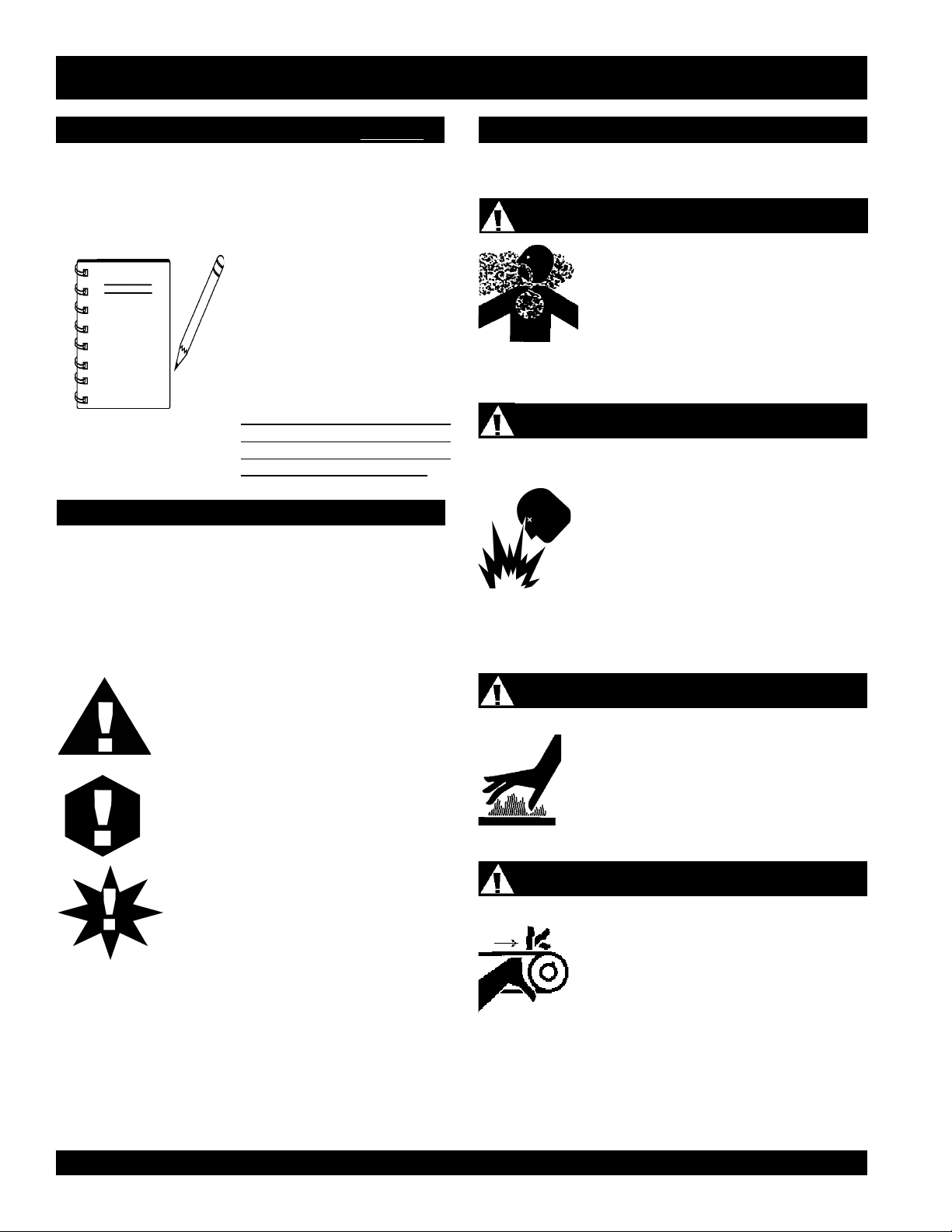
Lethal Exhaust Gases
Engine exhaust gases contain poisonous
carbon monoxide. This gas is colorless and
odorless, and can cause death if inhaled.
NEVER operate this equipment in a confined
area or enclosed structure that does not
provide ample free flow air.
Explosive Fuel
GASOLINE is extremely flammable, and its
vapors can cause an explosion if ignited. DO
NOT start the engine near spilled fuel or
combustible fluids. DO NOT fill the fuel tank
while the engine is running or hot. DO NOT
overfill tank, since spilled fuel could ignite if it
comes into contact with hot engine parts or
sparks from the ignition system. Store fuel in
approved containers, in well-ventilated areas
and away from sparks and flames. NEVER
use fuel as a cleaning agent.
DANGER: You WILL be KILLED or
SERIOUSLY injured if you do not follow
directions.
WARNING: You CAN be KILLED or
SERIOUSLY injured if you do not follow
directions.
CAUTION: You CAN be injured if you
do not follow directions.
Potential hazards associated with the MIX N' GO MIXER
operation will be referenced with Hazard Symbols which appear
throughout this manual, and will be referenced in conjunction
with Safety Message Alert Symbols.
Burn Hazards
Engine components can generate extreme heat.
To prevent burns, DO NOT touch these areas
while the engine is running or immediately after
operations. Never operate the engine with heat
shields or heat guards removed.
Rotating Parts
NEVER operate equipment with covers, or
guards removed. Keep fingers, hands, hair and
clothing away from all moving parts to prevent
injury.
PAGE 6 —MIX N' GO MIXER — PARTS & OPERATION MANUAL — REV. #1 (09/09/02)
Page 7
MIX N' GO MIXER — SAFETY MESSAGE ALERT SYMBOLS
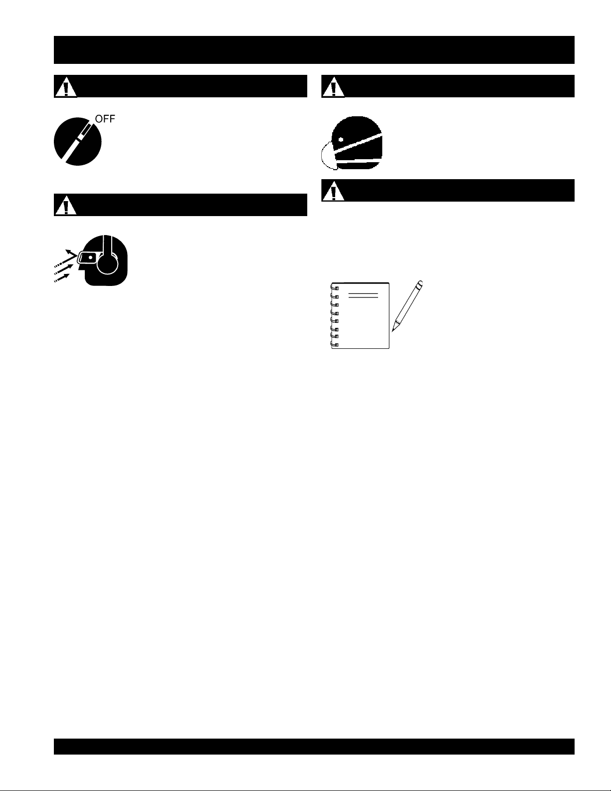
Accidental Starting
ALWAYS place the engine or electric motor
ON/OFF switch in the OFF position when the
mixer is not in use.
Sight and Hearing hazard
ALWAYS wear approved eye and hearing
protection.
Respiratory Hazard
ALWAYS wear approved respiratory
protection.
Equipment Damage Messages
Other important messages are provided throughout this manual
to help prevent damage to your mixer, other property, or the
surrounding environment.
This mixer, other property, or the
surrounding environment could
NOTE
be damaged if you do not follow
instructions.
MIX N' GO MIXER — PARTS & OPERATION MANUAL — REV. #1 (09/09/02) — PAGE 7
Page 8
RULES FOR SAFE OPERATION
■
DANGER:
Failure to follow instructions in this manual may
lead to serious injury or even death! This
equipment is to be operated by trained and
qualified personnel only! This equipment is for
industrial use only.
The following safety guidelines should always be used when
operating the Mix N' Go Mixer:
GENERAL SAFETY
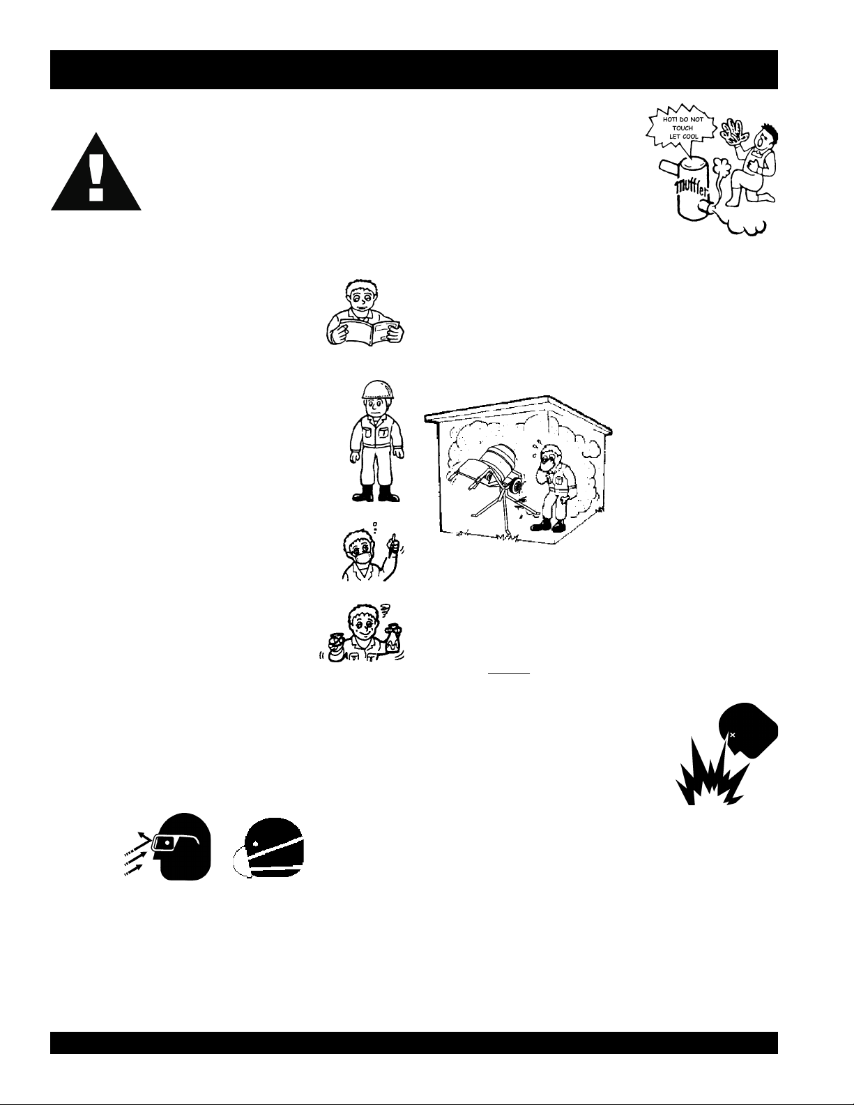
■
DO NOT operate or service this equipment before
reading this entire manual.
■
This equipment should not be operated by
persons under 18 years of age.
■
NEVER operate this equipment without proper
protective clothing, shatterproof glasses, steeltoed boots and other protective devices required
by the job.
■
NEVER operate this equipment when not feeling
well due to fatigue, illness or taking medicine.
NEVER touch the hot exhaust manifold,
muffler or cylinder. Allow these parts to
cool before servicing engine or mixer.
■
High Temperatures – Allow the engine to cool before adding
fuel or performing service and maintenance functions. Contact
hot
with
■
The engine of this mixer requires an adequate free flow of
cooling air.
or narrow area where free flow of the air is restricted. If the air
components can cause serious burns.
NEVER!
operate the roller mixer in any enclosed
flow is restricted it will cause
serious damage to the
mixer or engine and may
cause injury to people and
property. Remember the
mixer's engine (gasoline
models only) gives off
DEADLY gases.
■
NEVER operate this equipment under the
influence or drugs or alcohol.
■
Whenever necessary, replace nameplate, operation and
safety decals when they become difficult read.
■
ALWAYS check the machine for loosened threads or bolts
before starting.
■
ALWAYS wear proper respiratory (mask) hearing and eye
protection equipment when operating the mixer.
■
ALWAYS refuel in a well-ventilated area, away from sparks
and open flames.
■
ALWAYS use extreme caution when working with flammable
liquids. When refueling, stop the engine and allow it to cool.
DO NOT
could result from fuel vapors, or if fuel is spilled on a hot
engine.
■
NEVER operate the mixer in an explosive
atmosphere or near combustible
materials. An explosion or fire could result
causing severe
smoke around or near the machine. Fire or explosion
bodily harm or even
death.
■
Topping-off to filler port is dangerous, as it tends to spill fuel.
■
Refer to the
questions or information.
■
NEVER use accessories or attachments, which are not
recommended by Multiquip for this equipment. Damage to
the equipment and/or injury to user may result.
■
Manufacturer does not assume responsibility for any accident
due to equipment modifications.
Engine Owner's Manual
for engine technical
PAGE 8 —MIX N' GO MIXER — PARTS & OPERATION MANUAL — REV. #1 (09/09/02)
Page 9

■
NEVER Run engine without air cleaner. Severe engine
damage may occur.
■
ALWAYS read, understand, and follow procedures in
Operator’s Manual before attempting to operate equipment.
■
ALWAYS be sure the operator is familiar with proper safety
precautions and operations techniques before using roller.
■
ALWAYS store equipment properly when it is not being used.
Equipment should be stored in a clean, dry location out of the
reach of children.
■
■
■
■
NEVER leave the mixer unattended, turn off engine or electric
motor when unattended.
■
■
CAUTION must always be observed while servicing this mixer.
Rotating parts can cause injury if contacted.
■
Unauthorized equipment modifications will void all
Maintenance Safety
warranties.
■
■
Ensure that any trailing cable is protected against damage
and not liable to be tripped over or trapped underneath the
mixer.
■
Ensure any extention cables must be no longer than 30 meters
(100 feet) in length and that the wire section is 2.5 mm
■
DO NOT allow extension cord to come into contact with water
2
■
■
.
■
or fluids.
■
DO NOT expose power tools to
■
This mixer is intended for the production of concrete, mortar
rain
or
wet
conditions.
and plaster. Mixer must be used only for its intended purpose.
■
This mixer is not suitable for the mixing of
explosive
■
NEVER operate the mixer in an
substances.
explosive
flammable
atmosphere.
■
■
or
■
RULES FOR SAFE OPERATION
High Temperatures – Always stop engine and allow the
engine to cool before adding fuel, oil or performing service
hot
and maintenance functions. Contact with
cause serious burns.
NEVER disconnect any
These devices are intended for operator safety. Disconnection
of these devices can cause severe injury, bodily harm or even
death! Disconnection of any of these devices will void all
warranties.
"emergency or safety devices"
If mixer is equipped with an electric motor, operate
120 VAC, 60 Hz.
Make sure the
OFF/ON
power switch is always in the
position before inserting the mixer's power plug into an AC
receptacle (electric model only).
NEVER lubricate components or attempt service on a running
machine.
ALWAYS allow the machine a proper amount of time to cool
before servicing.
Keep the machinery in proper running condition.
Fix damage to the machine immediately and always replace
broken parts, or missing decals.
Dispose of hazardous waste properly. Examples of potentially
hazardous waste are used motor oil, fuel and fuel filters.
DO NOT use food or plastic containers to dispose of
hazardous waste.
DO NOT pour waste, oil or fuel directly onto the ground,
down a drain or into any water source.
components can
.
only
at
OFF
■
Before starting the mixer, check that all
guards
are in position
and correctly fitted.
■
DO NOT tip mixer onto drum mouth when the motor is running.
■
Keep area around the mixer
could cause persons to fall onto
■
ALWAYS ensure mixer is on level ground before mixing.
■
Become familiar with the controls of the machine before
clear of obstructions
moving parts
which
.
operating.
■
ALWAYS replace any worn or damaged warning decals.
■
Ensure the drum is
rotating
while filling and emptying the
drum.
■
DO NOT use mixer as a wheel barrel.
■
ALWAYS disconnect AC power plug from power source
before moving mixer (electric model only).
MIX N' GO MIXER — PARTS & OPERATION MANUAL — REV. #1 (09/09/02) — PAGE 9
Page 10
Emergencies
■
ALWAYS know the location of the nearest
■
ALWAYS know the location of the nearest
fire extinguisher
first aid kit
.
RULES FOR SAFE OPERATION
.
■
In emergencies
nearest phone or
Also know the phone numbers of the nearest
ambulance, doctor
information will be invaluable in the case of an
emergency.
always
know the location of the
keep a phone on the job site
and
fire department
.
. This
PAGE 10 —MIX N' GO MIXER — PARTS & OPERATION MANUAL — REV. #1 (09/09/02)
Page 11

OPERATION AND SAFETY DECALS
WARNING!
ALARMA!
AVERTISSEMENT!
ENGLISH - WARNING! TO REDUCE THE RISK OF INJURY, USER MUST READ AND UNDERSTAND INSTRUCTION MANUAL
ESPAÑOL - ATENCION! PARA REDUCIR EL RIESGO DEL LESIONES EL USUARIO DEBE LEER Y ENTENDER EL MANUAL DE INSTRUCCIONES
FRANÇAIS - ATTENTION! AFIN DE DIMINUER LE RISQUE DE BLESSURES L’UTILISATEUR DOIT LIRE ET COMPRENDRE CE MANUEL D’ INSTRUCTIONS
DCL251
Machine Safety Decals
The Mix N' Go mixer is equipped with a number of safety decals. These decals are provided for operator safety and maintenance
information. The illustration below and on the next page shows these decals as they appear on the machine. Should any of these
decals become unreadable, replacements can be obtained from your dealer.
P/N DCL251
TBD
MIX N' GO MIXER — PARTS & OPERATION MANUAL — REV. #1 (09/09/02) — PAGE 11
Page 12
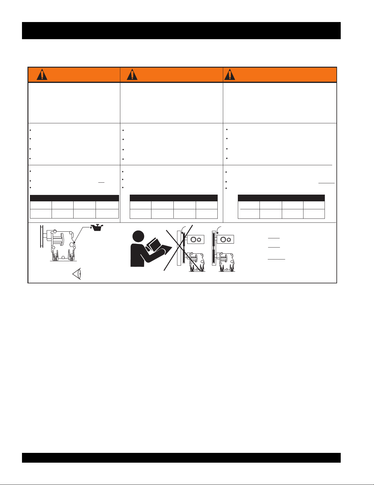
WARNING! ADVERTENCIA! AVERTISSEMENT!
1. Read owner’s manual before operating mixer.
2. Keep unauthorized and untrained people away
from mixer during operation.
3. Make sure all safety devices (guards) are in place
before mixer is started.
4. Keep hands and fingers away from moving objects.
5. leave mixer unattended when operating.NEVER
6. check V-belt before starting mixer.ALWAYS
Make sure engine is turned off and spark plug wire is
disconnected before cleaning mixer.
DO NOT
ventilation is required.
ALWAYS
adding fuel or oil.
Make sure power cord has been disconnected from power
source before cleaning mixer.
This electric motor is for .115 VAC operation only
ALWAYS
below:
No. 12 Wire
50 feet
(15.24 meters)
GASOLINE ENGINE
operate mixer in an enclosed area, proper
stop the engine and allow engine to cool before
check fuel, oil and air filter before starting engine.ALWAYS
ELECTRIC MOTOR
use an extension cord of proper size, see chart
EXTENSION CORD SIZE
No. 10 Wire
75 feet
(22.86 meters)
No. 8 Wire
100 feet
(30.48 meters)
No. 6 Wire
200 feet
(60.96 meters)
OPERATION AND SAFETY DECALS
1. Lea el manual de operació antes de usar la mezcladora.
2. Mantenga personas que no estén autorizadas o capacitadas
alejades de la mezcladora durante el funcionamiento de la
máquina.
3. Asegúreseque todos los aparatos de seguridad estén
trabajando apropiadamente antes de usar la mezcladora.
4. Mantenga las monos y dedos alejados de objetos en moviminto.
5. se aleje de la mezclaora mientras ésta, este trabajando!NUNCA
6. inspeccione la banda antes de encender la mezcladora.SIEMPRE
Asegure que la máquina este apagada y el alambre de la bujía
este desconectado antes de empezar a limpiar la mezcladora.
NO
estar en una área que tenga apropiada ventilación.
SIEMPRE
ponerle gasolina o aceite.
SIEMPRE
encender la máquina.
Asegúrese que el cable de corriente esté de empezar a limpiar
la mezcladora.
Este motor elétrico está
alterna 115 voltios
SIEMPRE
como muestra el diagrama abajo:
(15.24 metros)
MÁQUINAS DE GASOLINA
encienda la mezcladora en una área cerrada; es necesario
apague la máquina y permita que se enfrie antes de
revise la gasolina, aceite, y el filtro del air antes de
MOTOR ELÉCTRICO
de .
use el tamaño de extensiones de alambre indicado
Alambre
Numéro 12
50 pies
solamente capacitado para corriente
TAMAÑO DE EXTENSIÓN
Alambre
Numéro 10
75 pies
(22.86 metros)
Alambre
Numéro 8
100 pies
(30.48 metros)
Alambre
Numéro 6
200 pies
(60.96 metros)
1. Lisez le manual d’ utilisation avant d’ utiliser le le malaxeur.
2. Seul un personnel qualifié peut être authorisé à se trouver à proximité
du malaxeur quand il est en opération.
3. Assurez vous que tous les dispositifs de sécurité sont en place avant
de mettre le malaxeur en marche.
4. Gardez les mains et doigts loin de toute piè en mouvement.
5. jamais le malaxeur sans surveillance quand il est en
NE LAISSEZ
opération.
6. toujours vérifier la courroie avant de mettre le malaxeur
VEUILLEZ
en marche.
Assurez vous que le moteur est arrêté et que le fil de la bougie est
débranché avant de nettoyer le malaxeur.
N’ UTILISEZ
de travailler dans un endroit avec une bonne aération.
VEUILLEZ
marche.
VÉRIFIEZ
air avant de mettre le moteur en marche.
Assures vous toujours que le cable a été débranché de la prise de
courant avant de nettoyer le malaxeur.
Ce moteur électrique à été conçu pour opération à 115 volts seulement.
Il faut toujours utiliser une rallonge de taille appropriée, veuillez s’il vous
référer au diagramme suivant:
Numéro 12
50 pieds
(15.24 métres)
MOTEUR À ESSENCE
pas le malaxeur dans un endroit fermé, il est nécessaire
toujours vé la courroie avant de mettre le malaxeur en
toujours le niveau d’essence et d’huile ainsi que le filtre à
MOTEUR ÉLECTRIQUE
TAILLE DE LA RALLONGE
Cable
Cable
Numéro 10
50 pieds
(15.24 métres)
Cable
Numéro 8
50 pieds
(15.24 métres)
Cable
Numéro 6
50 pieds
(15.24 métres)
ELECTRIC
MOTOR
MOTOR
ELÉCTRICO
MOTEUR
ÉLECTRIQUE
REMOVE BOLT AND FILL
WITH EP. 90 GEAR OIL
REMOVER EL TORÑILLO Y
LLENAR CON ACEITE DE
ENGRNAJE EP. 90
ÔTEZ LE BOULON ET
REMPLISSEZ AVEC DE I’HUILE
EP. 90 À ENGRENAGES
CHECK DAILY
REVISAR DIARIO
VÉRIFIEZ QUOTIDIENNEMENT
P/N DCL250
ELECTRIC
MOTOR
MOTOR
ELÉCTRICO
MOTEUR
ÉLECTRIQUE
NEVER! OPERATE MIXER WITH
V-BELT COVER REMOVED.
NUNCA! MANEJE LA MEZCLADORA
SIN LA COBERTURA DE BANDA-V
REMOVIDA.
N’ UTILISEZ! JAMAIS LE MALAXEUR
SANS LE COUVERCLE DE LA COURROIE.
DCL250
PAGE 12 —MIX N' GO MIXER — PARTS & OPERATION MANUAL — REV. #1 (09/09/02)
Page 13
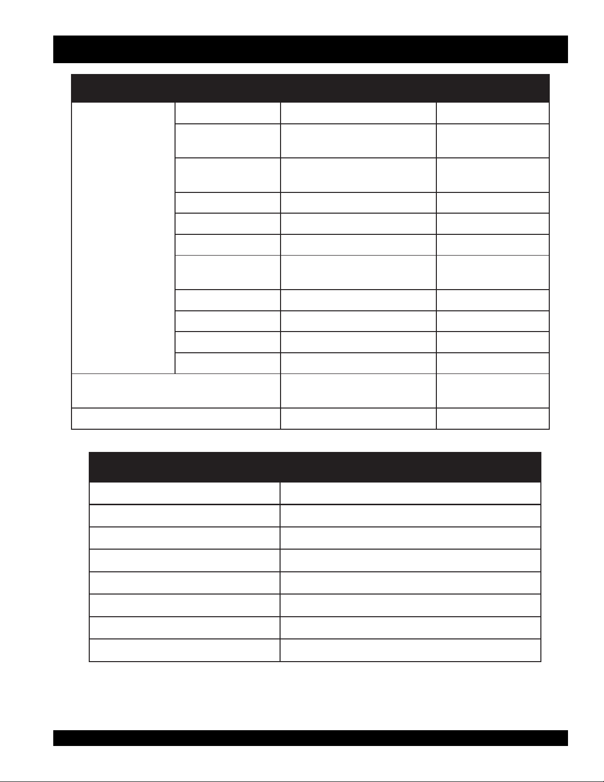
MIX N' GO MIXER — SPECIFICATIONS
ledoM2AQ2K001GADNOH403EYL71RODLAB
)rotoMcirtcelE&enignE(snoitacificepS.1elbaT
epyTrednilyCelgniS,evlavediS,ekorts-4
ekortSXeroB
tnemecalpsiD)cc89(.ni.uc0.6A/N
tuptuOxaM.M.P.R006,3ta.P.H5.2MPR054,3/.P.H4/3
rotoMcirtcelE/enignE
leuFenilosaGdedaelnUA/N
)HxWxL(snoisnemiD
thgieWteNyrD
deepSeldIdradnatS.M.P.R001±004,1A/N
yticapaCknaTleuF
yticapaCliOebuL)sretiL54.0(strauQ.S.U84.0A/N
dohteMlortnoCdeepSepyTthgiew-ylFlagufirtneCA/N
dohteMgnitratStratSlioceRA/N
.ni1.81X.ni5.02
)mm64xmm25(
snollaG.S.U73.0.xorppA
)sretiL4.1(
.ni6.31X6.01x8.01
)mm543X072X572(
).gK7.8(sbl2.91).gK4.5(.sbl21.xorppA
A/N
A/N
elgniS,CAV021,PH4/3
rotoMcirtcelEesahP
.ni0.8X0.6x57.11
)mm302X251X892(
snoitacificepSrexiMoG'NxiM.2elbaT
thgieH )mm6.368(.ni43
htdiW )mm2.485(.ni8/5-32
htgneL )mm2.912,1(.ni2/1-84
thgieWdnatS )gK9.51(.sbl53
3
yticapaCmurDmumixaM m31.0(.tf.uc5.4
)gab2/1(yticapaCgnixiMmumixaM m80.0(.tf.uc0.3
rotoMcirtcelE-thgieWnedalnU )gK5.85(.sbl921
enignEenilosaG-thgieWnedalnU )gK6.26(.sbl831
MIX N' GO MIXER — PARTS & OPERATION MANUAL — REV. #1 (09/09/02) — PAGE 13
)
3
)
Page 14
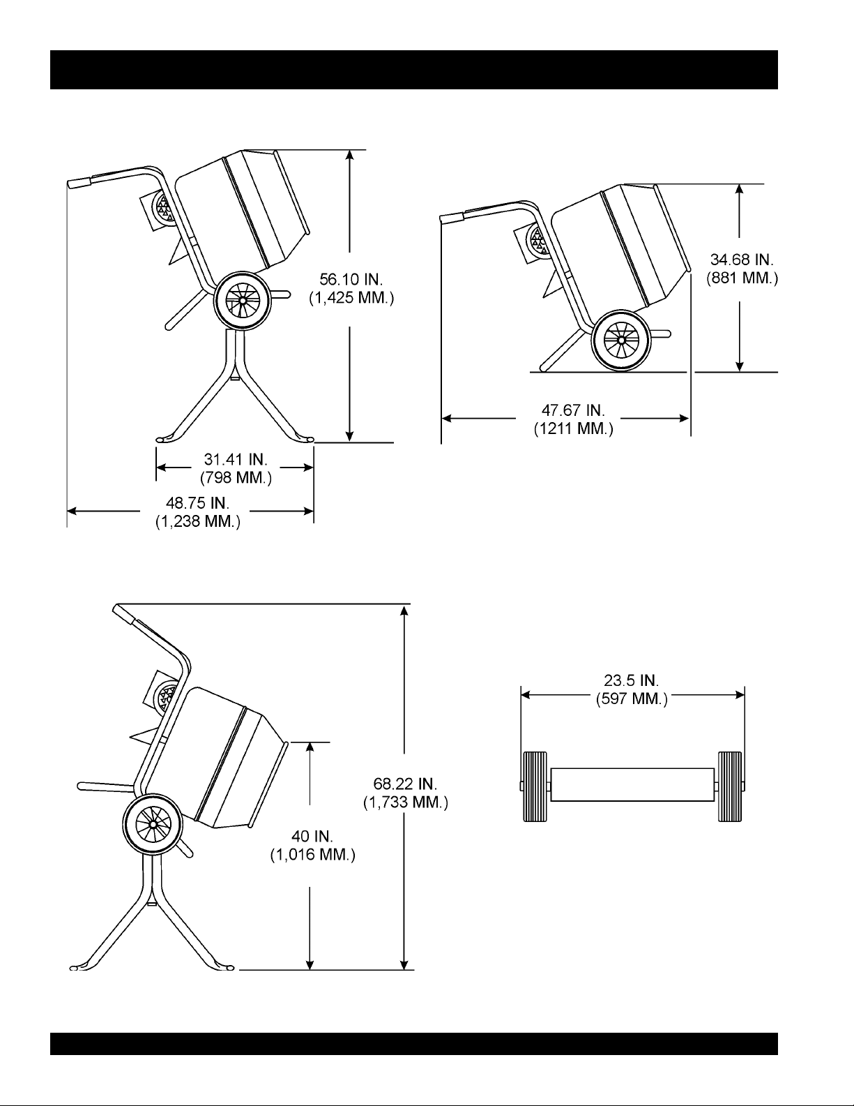
MIX N' GO MIXER — DIMENSIONS (MIXER)
Figure 1. Mix N' Go
Mixer Dimensions
PAGE 14 —MIX N' GO MIXER — PARTS & OPERATION MANUAL — REV. #1 (09/09/02)
Page 15
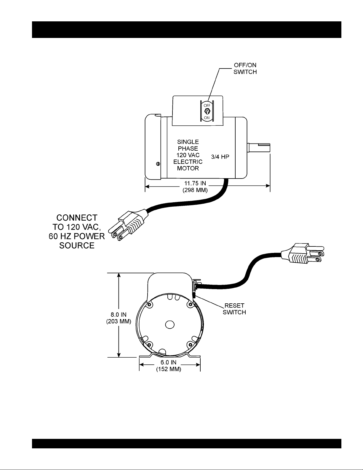
MIX N' GO MIXER — DIMENSIONS (ELECTRIC MOTOR)
Figure 2. Electric Motor
MIX N' GO MIXER — PARTS & OPERATION MANUAL — REV. #1 (09/09/02) — PAGE 15
Page 16
MIX N' GO MIXER — GENERAL INFORMATION
APPLICATION
This mixer is
mortar
purposes and is not suitable for the mixing of
explosive
only
and
intended for the production of
plaster
. The mixer must be used for its intended
concrete
flammable
substances. The mixer must not be used in an
explosive atmosphere.
POWER PLANTS
This portable mixer is powered by either a Honda G100K2,
4-stroke, side valve, single cylinder, gasoline engine rated
at 2.5 hp @3,600 rpm. or a 0.75 hp electric motor.
DRUM ASSEMBLY
The drum is instantly removable by unscrewing counterclockwise. When inserting drum onto gearbox shaft, make sure
that drum is fully screwed onto shoulder or threads may be
damaged. Use extreme care when screwing on the drum,
spinning drum onto the gearbox shaft too fast may damage
gearbox.
ELECTRICAL
If mixer is equipped with an
electric motor
, make sure that
PORTABLE GENERATORS
,
When using a
output of 2.5 kw and be continuous rated.
or
GEARBOX
The gearbox oil level has been preset at the
shipping. Before inspecting the gearbox oil level (Figures 30
and 31), make sure the gearbox is cold before removing the
filler plug. Fill up with EP90. or similar gear oil.
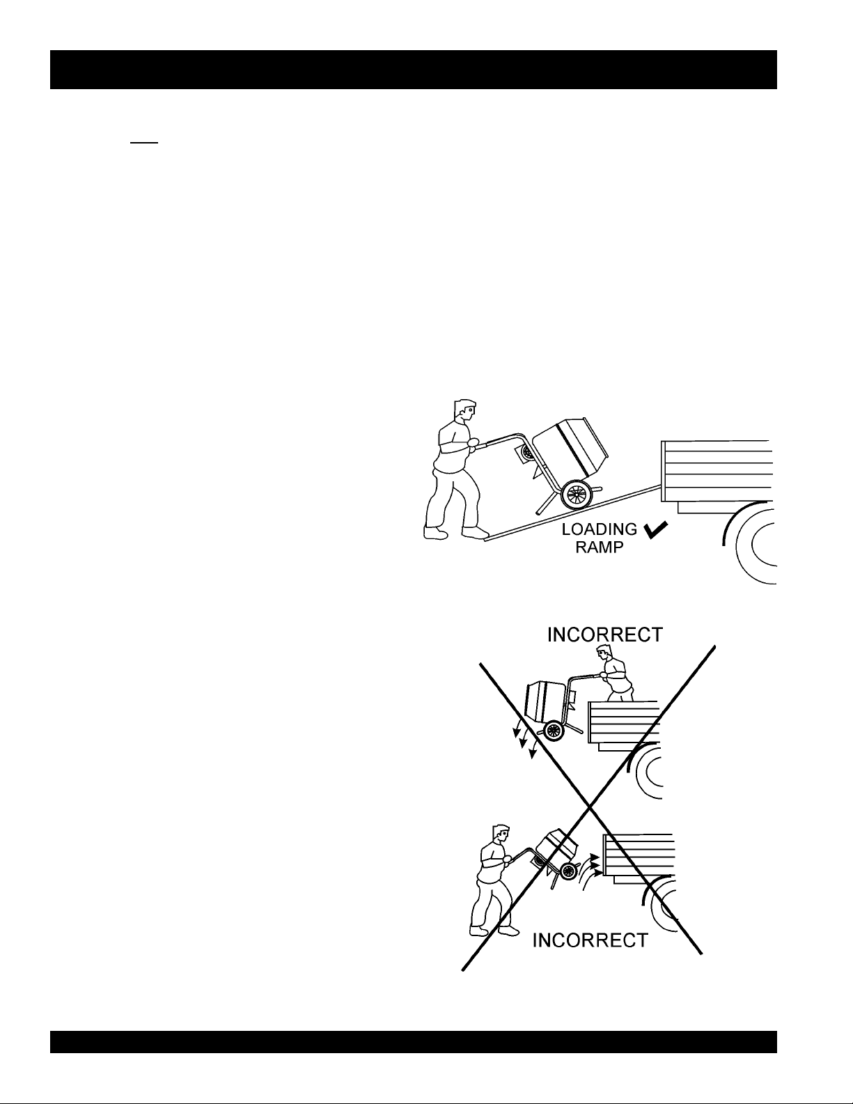
TRANSPORTING THE MIXER
Use a ramp (Figure 3) to load and unload the mixer from the
transport vehicle. Never drop the mixer onto the ground; damage
to the mixer could result.
the power being supplied to the motor corresponds to the
voltage rating label on the motor. Supplying the wrong voltage
to the electric motor will cause severe electrical damage to
the motor.
portable generator
it must have a minimum
factory
prior to
Always make sure that
is in the
It is
OFF
position before applying power.
strongly recommended
mixer's power cord into a receptacle, that a G.F.C.I. (
Fault Current Interrupter
EXTENSION CABLES
OFF/ON
switch on the electric motor
that when plugging in the
) receptacle be used.
Ground
The extension cable should be a 3-wire configuration that
includes a ground wire that conforms to UL code. The wire
cross section must be a minimum of 2.5 mm
2
. Choose an
extension cord of adequate current carrying as Reference in
Table 5. Remember
distance
affects the wire size of the
extension cable.
Ensure that the extension cable is carefully laid out avoiding
wet areas, sharp edges
and locations where vehicles
might run over it. Avoid allowing the extension cable to be
trapped underneath the mixer.
Unroll the extension cable fully or it will overheat and could
catch fire. Make sure that all extension cable connections
are dry and safe. Replace any defective or badly worn extension cable immediately.
Figure 3. Mixer Loading
PAGE 16 —MIX N' GO MIXER — PARTS & OPERATION MANUAL — REV. #1 (09/09/02)
Page 17
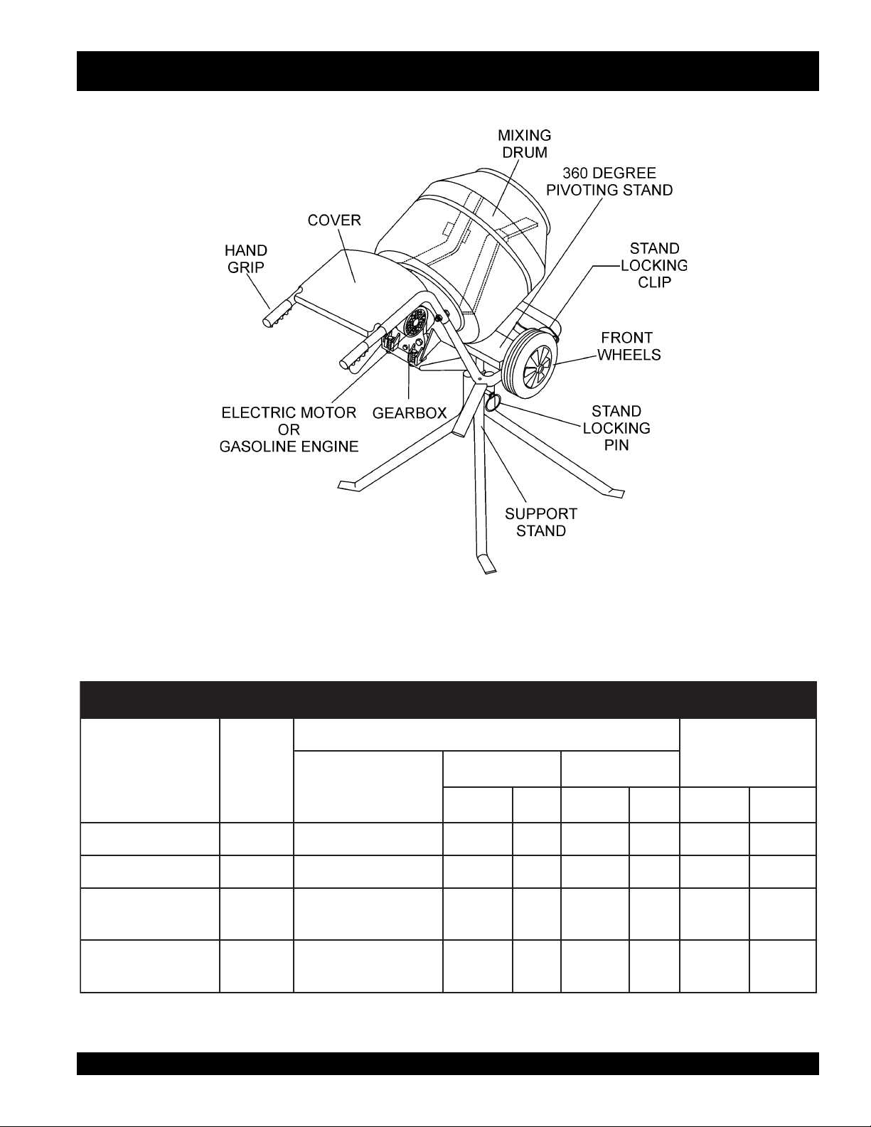
MIX N' GO MIXER — MIXER COMPONENTS
Figure 4 shows the basic components of the
Mixer
.
Mix N' Go
Figure 4. Mixer Components
STNIHGNIXIM.3elbaT
SEITITNAUQHCTAB
SNOITACILPPA
yranidrOtsoM
snoitadnuoF
ssaMhguoR
etercnoC
,sroolFthgitretaW
.ctE,stiP,sknaT
XIM
SOITAR
gaB
4:2:1GAB2/14/1-1532/1-2173 58
6:3:1GAB3/14/1-1532/1-2174/3-287
8:4:1GAB4/14/1-1532/1-2174/3-287
3:2/1-1:1GAB3/24/1-1533173 58
.sbl211TNEMEC
).sgK05(
DNASENOTS
.TF.UCRTL.TF.UCRTL.TF.UCRTL
HCTAB.XORPPA
TUPTUO
MIX N' GO MIXER — PARTS & OPERATION MANUAL — REV. #1 (09/09/02) — PAGE 17
Page 18
MIX N' GO MIXER — BASIC ENGINE
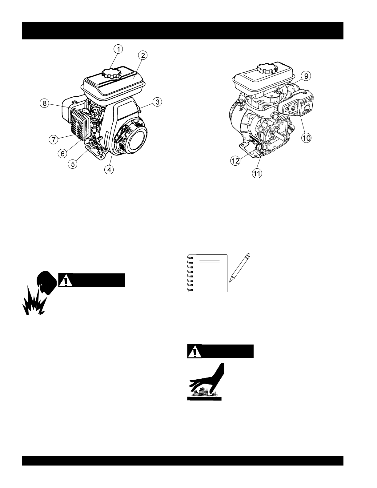
Figure 5. Engine Controls and Components
INITIAL SERVICING
The engine (Figure 5) must be checked for proper lubrication and
filled with fuel prior to operation. Refer to the manufacturers engine
manual for instructions and details of operation and servicing. The
engine shown above is a HONDA engine, operation for other
types of engines may vary somewhat.
1. Fuel Filler Cap – Remove this cap to add unleaded
gasoline to the fuel tank. Make sure cap is tightened
securely. DO NOT over fill.
DANGER
Adding fuel to the tank should be done only when
the engine is stopped and has had an opportunity to
cool down. In the event of a fuel spill, DO NOT
attempt to start the engine until the fuel residue has been completely
wiped up, and the area surrounding the engine is dry.
2. Fuel Tank – Holds unleaded gasoline. For additional
information refer to engine owner's manual.
ON
3. Engine ON/OFF Switch –
OFF
starting,
4. Recoil Starter (pull rope) – Manual-starting method. Pull
the starter grip until resistance is felt, then pull briskly and
smoothly.
5. Throttle Lever – Used to adjust engine RPM speed (lever
advanced forward
FAST
).
Fuel Valve Lever – OPEN to let fuel flow, CLOSE to stop
6.
the flow of fuel.
position stops engine operation.
SLOW
position permits engine
, lever back toward operator
7. Air Cleaner – Prevents dirt and other debris from entering
the fuel system. Remove wing-nut on top of air filter
cannister to gain access to filter element.
8. Choke Lever – Used in the starting of a cold engine, or in
cold weather conditions. The choke enriches the fuel
mixture.
NOTE
9. Spark Plug – Provides spark to the ignition system. Set
spark plug gap to 0.6 - 0.7 mm (0.024 - 0.028 inch) Clean
spark plug once a week.
10. Muffler – Used to reduce noise and emissions.
11. Oil Drain Plug – Remove this plug to remove oil from the
engine's crankcase.
12. Dipstick/Oil Filler Cap – Remove this cap to determine if
the engine oil is low. Add oil through this filler port as
recommended in Table 4.
Operating the engine without an air
filter, with a damaged air filter, or a
filter in need of replacement will
allow dirt to enter the engine,
causing rapid engine wear.
WARNING
Engine components can generate extreme heat.
To prevent burns, DO NOT touch these areas
while the engine is running or immediately after
operating. NEVER operate the engine with the
muffler removed.
PAGE 18 —MIX N' GO MIXER — PARTS & OPERATION MANUAL — REV. #1 (09/09/02)
Page 19
MIX N' GO MIXER — ASSEMBLY INSTRUCTIONS
Assembly
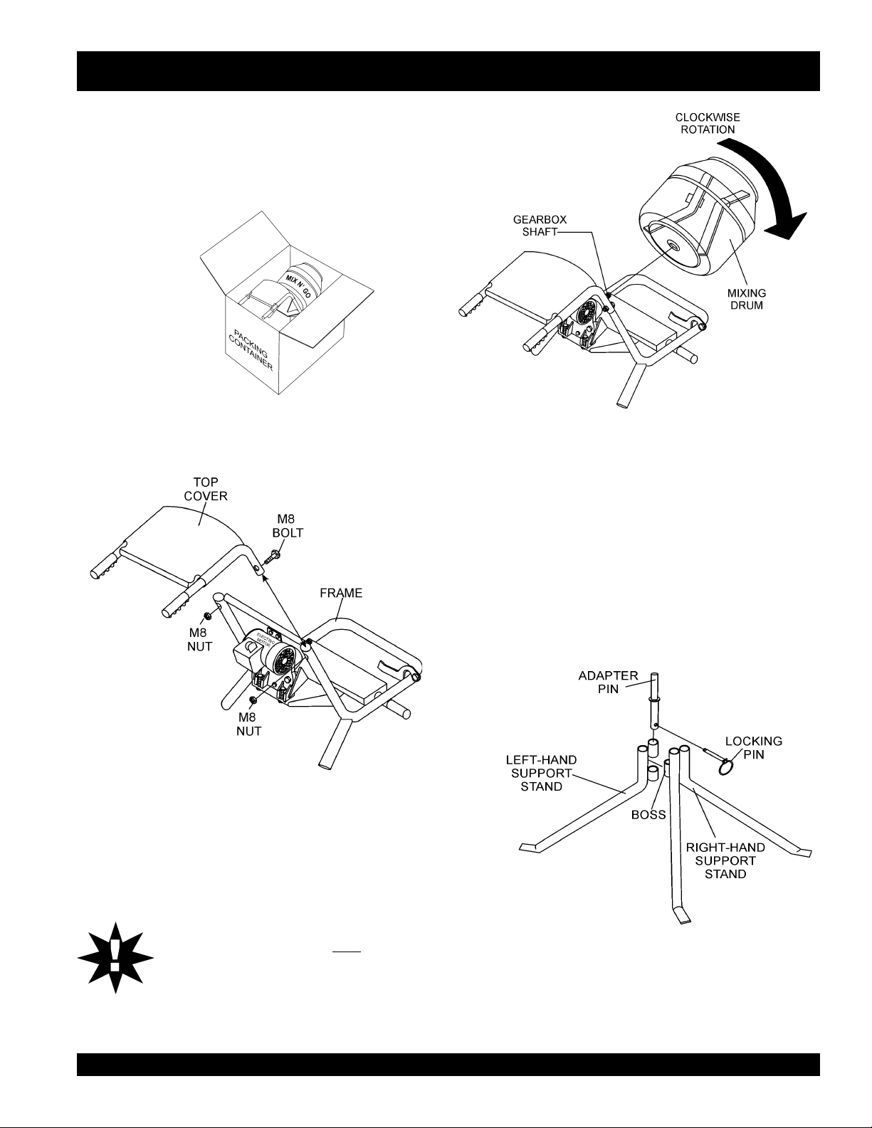
1. Remove the mixer drum and associated components from
the packing container (Figure 6). Match the components
against the parts list to make sure that they are all accounted
for.
Figure 6. Packing Container
2. Place the mixer frame on a secure level surface, and attach
the top cover as shown in Figure 7.
Figure 8. Mixing Drum Placement
4. Place the two halves of the support stand together (Figure 9).
The left support stand fits into the center boss on the right
support stand.
5. Insert the adapter pin through bosses as shown in Figure 9.
Once the adapter pin has been inserted and aligned, insert
the locking pin. Place the round part of the locking pin over
the bottom section of the adapter pin.
Figure 7. Top Cover Placement
3. Fit the mixing drum onto gearbox shaft as shown in Figure
8. Rotate drum in a clockwise direction, make sure the drum
fits right up to the shoulder on the gearbox shaft.
CAUTIONCAUTION
CAUTION
CAUTIONCAUTION
DO NOT
damage the gearbox.
MIX N' GO MIXER — PARTS & OPERATION MANUAL — REV. #1 (09/09/02) — PAGE 19
spin
the drum on
fast
, as this may
Figure 9. Support Stand
Page 20
MIX N' GO MIXER — ASSEMBLY INSTRUCTIONS
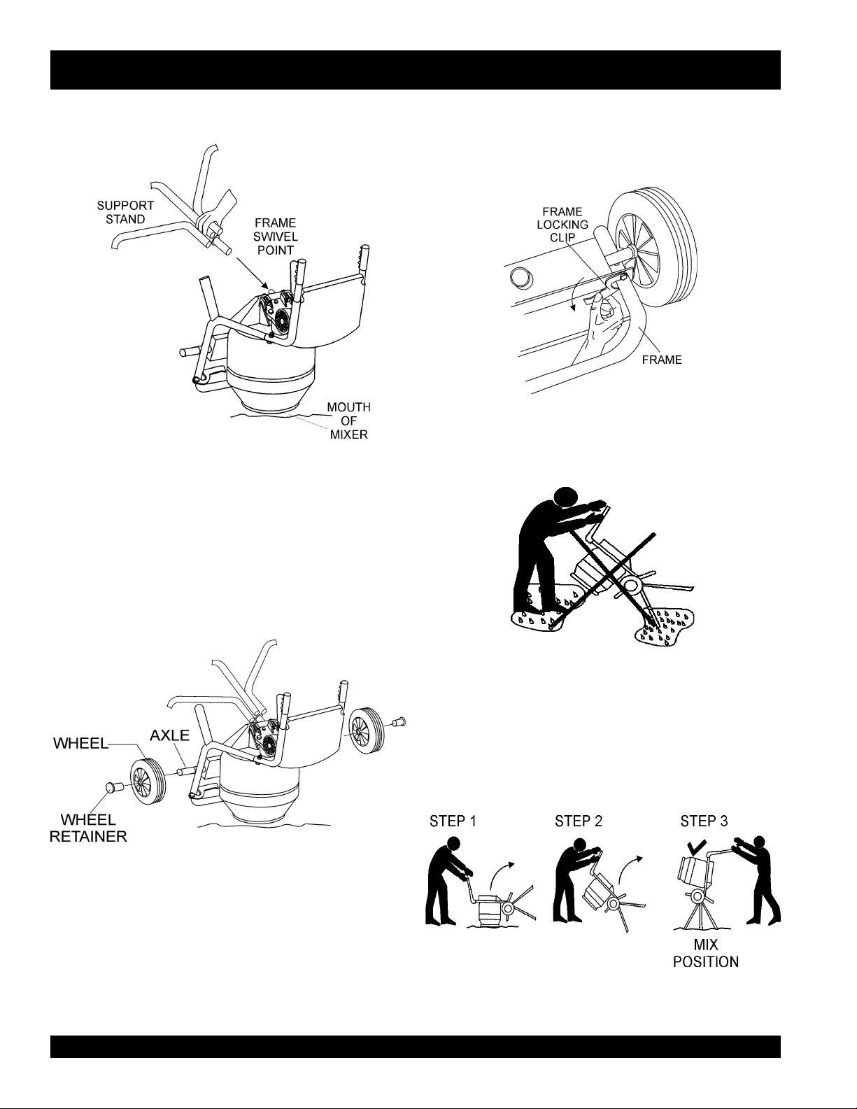
6. Tip mixer onto mouth as shown in Figure 10, and insert
support stand into frame swivel point.
Figure 10. Attaching Support Stand
7. Remove both wheels and wheel retainers from the packing
container.
9. Before attempting to lift mixer, locate the frame locking clip.
Attach the locking clip as shown in Figure 12. This will prevent
the mixing drum from moving when the mixer is positioned
in an upright position.
10. DO NOT tilt the mixer on a wet, smooth or slippery surface.
Figure 12. Frame Locking Clip
8. Place one wheel on each side of the mixer's axle as shown
in Figure 11. Position wheel retainer over axle to secure
wheel in place. Use a rubber mallet when striking wheel
retainer.
11. Once the stand has been assembled, and the locking clip has
been secured, begin tilting the mixer to an upright position.
Remember
in Figure 14.
Figure 11. Wheels and Wheel Retainers
Figure 13. Slippery or Wet Surfaces
always
tilt from the front of the mixer as shown
Figure 14. Tilting Mixer to Upright Position
PAGE 20 —MIX N' GO MIXER — PARTS & OPERATION MANUAL — REV. #1 (09/09/02)
Page 21
MIX N' GO MIXER — PRE-INSPECTION (GASOLINE ENGINE)
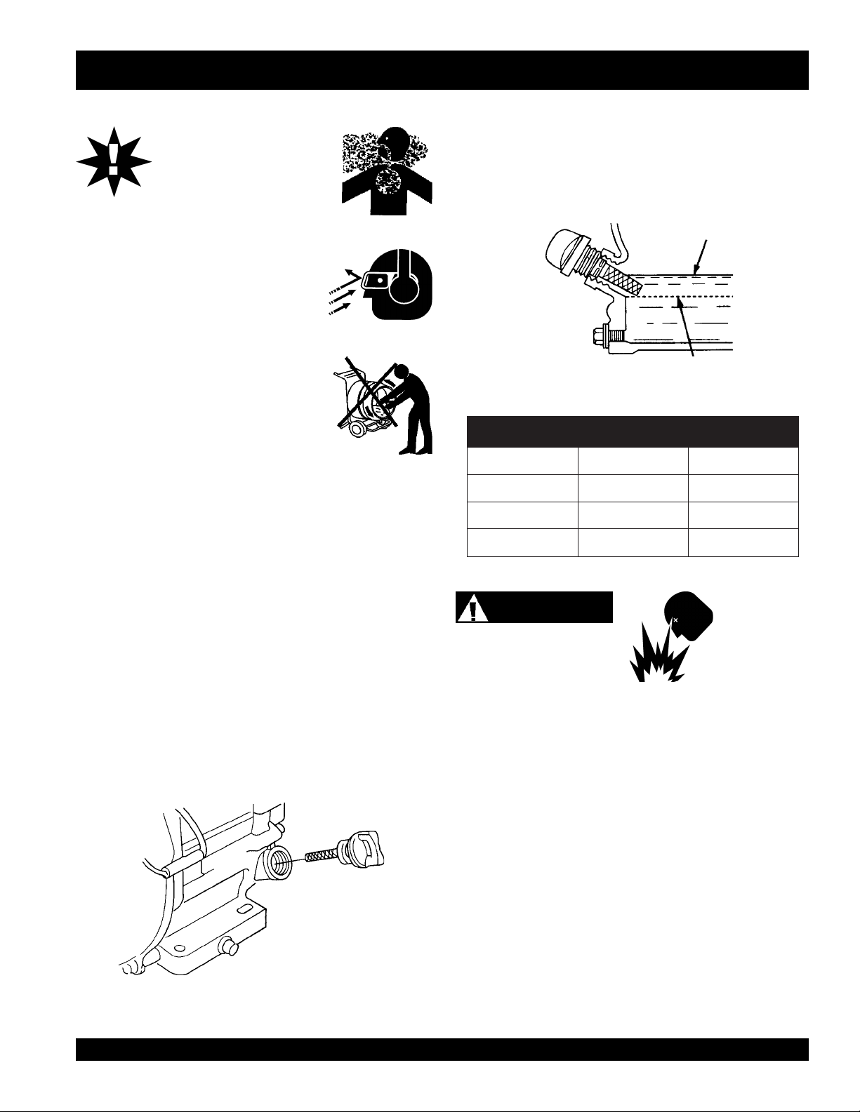
epyTliO.4elbaT
nosaeS erutarepmeT epyTliO
remmuS rehgiHroC°52 03-W01EAS
llaF/gnirpS C°01~C°52 02/03-W01EAS
retniW rewoLroC°0 01-W01EAS
CAUTIONCAUTION
CAUTION
CAUTIONCAUTION
NEVER operate the mixer in
a confined area or enclosed
area structure that does not
provide ample
ALWAYS wear approved eye and hearing
protection before operating the mixer.
NEVER place hands inside drum while the
engine is running. ALWAYS shut the engine
down before performing any kind of
maintenance service on the mixer.
Before Starting
1. Read safety instructions at the beginning of manual.
free flow of air
.
3. Insert and remove the dipstick without screwing it into the filler
4. If the oil level is low (Figure 16), fill to the edge of the oil filler
neck. Check the oil level shown on the dipstick.
hole with the recommended oil type (Table 4). Maximum oil
capacity is 0.48 quarts (.45 liters)
Figure 16. Engine Oil Dipstick (Oil Level)
2. Clean the mixer, removing dirt and dust, particularly the
engine cooling air inlet, carburetor and air cleaner.
3. Check the air filter for dirt and dust. If air filter is dirty, replace
air filter with a new one as required.
4. Check carburetor for external dirt and dust. Clean with dry
compressed air.
5. Check fastening nuts and bolts for tightness.
Engine Oil Check
1. To check the engine oil level, place the mixer on secure
level ground with the engine stopped.
2. Remove the filler dipstick from the engine oil filler hole
(Figure 15) and wipe clean.
Fuel Check
Motor fuels are highly flammable and can be dangerous if
mishandled. DO NOT smoke while refueling. DO NOT attempt
to refuel the mixer if the engine is
1. Remove the gasoline cap located on top of fuel tank.
2. Visually inspect to see if fuel level is low. If fuel is low, replenish
with unleaded fuel.
3. When refueling, be sure to use a strainer for filtration. DO
NOT top-off fuel. Wipe up any spilled fuel.
V-Belt Check
Explosive Fuel
hot! or running
.
Figure 15. Engine Oil Dipstick (Removal)
MIX N' GO MIXER — PARTS & OPERATION MANUAL — REV. #1 (09/09/02) — PAGE 21
A worn or damaged V-belt can adversely affect the performance
of the trowel. If a V-belt is defective or worn simply replace the Vbelt as outlined in the maintenance section of this manual.
Page 22
MIX N' GO MIXER — INITIAL START-UP (ELECTRIC MOTOR)
Initial Start-up Instructions (Electric Motor)
Starting
CAUTION:CAUTION:
CAUTION:
CAUTION:CAUTION:
DO NOT attempt to operate the mixer until
the Safety, General Information and
Inspection sections have been read and
understood.
1. Before starting, make sure mixer is positioned on a secure
flat surface to prevent tipping.
2. Use an extension cord (see Table 5) of adequate current
carrying capacity, insert the electric motor's power plug into
one end of the extension cord.
NEVER!
3.
4.
NEVER!
use a
worn
or
frayed
extension cord.
operate mixer with V-belt cover removed.
eziSdroCnoisnetxE.5elbaT
5. Plug the other end of the extension cord into a 120 VAC
G.F.C.I. protected receptacle. Remember the power requirements for this electric motor is 120 VAC, 60 Hz. The use of
any other input voltage will severely damage the motor.
WARNING:WARNING:
WARNING:
WARNING:WARNING:
WARNING:WARNING:
WARNING:
WARNING:WARNING:
ALWAYS read the label on the electric motor
before applying power. The label will indicate the
proper power requirements for the motor.
Remember the use of any other input voltage will
severely damage the motor.
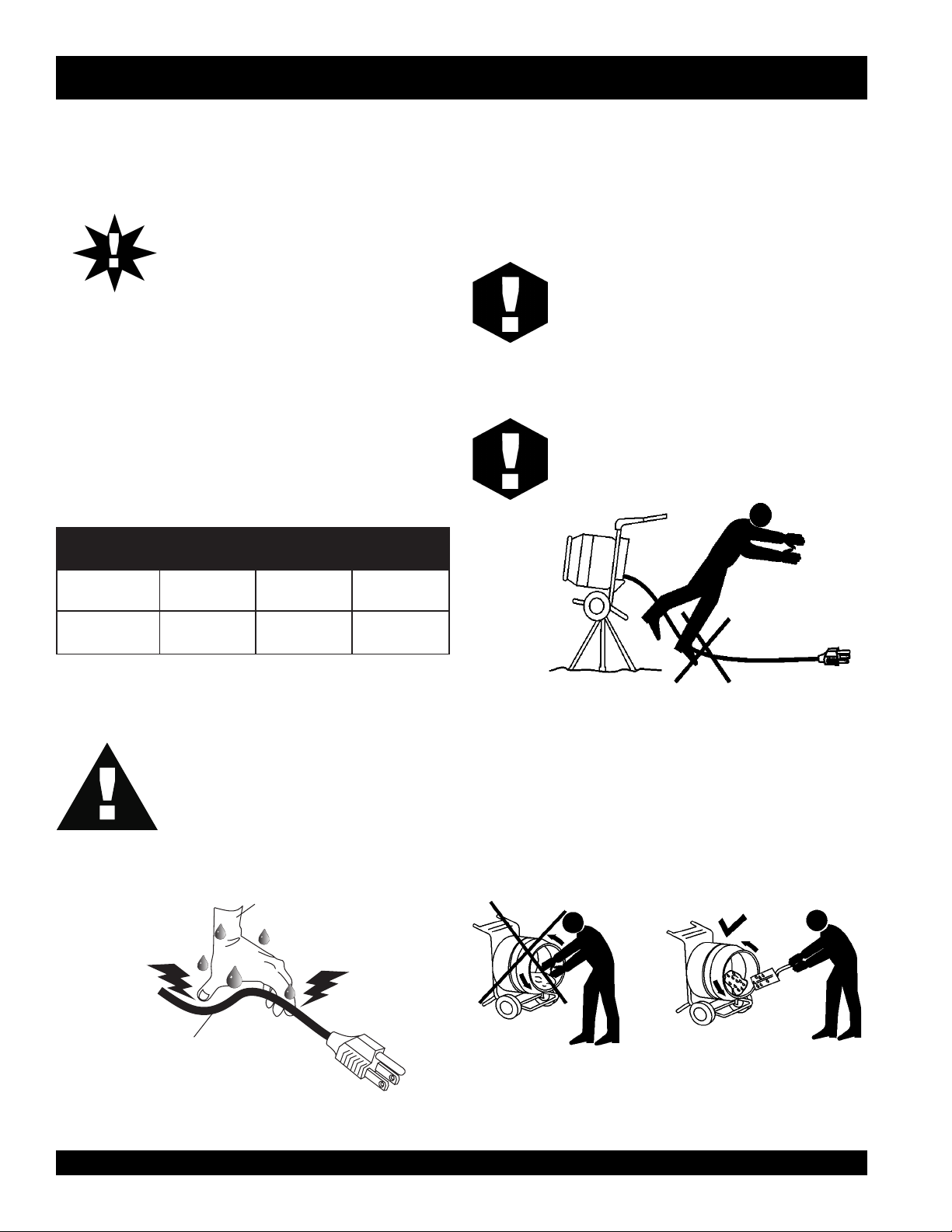
To prevent tripping (Figure 18) of both the mixer
and personnel, position the extension cord so that
it lays flat and is not curled underneath the mixer.
eriW21.oNeriW01.oNeriW8.oNeriW6.oN
)teef(05
)sretem42.51(
DANGERDANGER
DANGER
DANGERDANGER
NEVER!
with
when it is connected to a power source. The
possibly exists of electrical shock
(electrocution) even death.
water directly on the electric motor.
)teef(57
sretem68.22(
touch the power cord (Figure 17)
wet hands
HANDS
or while
WET
)teef(001
sretem84.03(
standing in water
NEVER!
)teef(002
sretem69.06(
spray
Figure 18. Mixer (Tripping)
6. The drum should be rotating allowing the mixing process to
begin. Use a shovel (Figure 19) to place the cement mix
inside the drum, add water as required. Be careful to only
tip
place the
all the way inside the drum will cause the shovel to strike the
blades. This condition will make the shovel rotate, and could
cause injury to personnel.
of the shovel inside the drum. Placing the shovel
POWER
CORD
(POWER ON)
Figure 17. Extension Cord (Wet Hands)
PAGE 22 —MIX N' GO MIXER — PARTS & OPERATION MANUAL — REV. #1 (09/09/02)
Figure 19. Mixing Drum (Placing cement Mix))
6. See Table 3 for mixing hints.
drum while the drum is rotating.
NEVER!
place hands inside the
Page 23

MIX N' GO MIXER — INITIAL START-UP (GASOLINE ENGINE)
DO NOT attempt to operate the mixer until
the Safety, General Information and
Inspection sections of this manual have
been read and thoroughly understood.
This section is intended to assist the operator with the initial
start-up of the walk-behind trowel. It is extremely important that
this section be read carefully before attempting to use the trowel
in the field.
Starting the Engine (
1. Place the engine
position.
HONDA
fuel valve lever
engine)
(Figure 20) to the "ON"
3. Place the
if starting a
4. Place the
if starting a
choke lever
cold
Figure 22. Engine Choke Lever (Open)
choke lever
warm engine
(Figure 22) in the "
engine.
(Figure 23) in the "
or the
OPEN
" position
CLOSED
" position
temperature is warm.
Figure 20. Engine Fuel Valve Lever (ON Position)
2. Place the trowel's
position.
Figure 21. Throttle Lever (Idle Position)
throttle lever
(Figure 21) to the "IDLE"
Figure 23. Engine Choke Lever (Closed)
5. Place the
position.
engine ON/OFF switch
(Figure 24) in the "
ON
"
Figure 24. Engine ON/OFF Switch (ON Position)
MIX N' GO MIXER — PARTS & OPERATION MANUAL — REV. #1 (09/09/02) — PAGE 23
Page 24

MIX N' GO MIXER — INITIAL START-UP (GASOLINE ENGINE)
6. Grasp the starter grip (Figure 25) and slowly pull it out. The
resistance becomes the hardest at a certain position, corresponding to the compression point. Pull the starter grip briskly
and smoothly for starting.
Figure 25. Starter Grip
7. If the engine has started, slowly return the choke lever
(Figure 23 ) to the
started repeat steps 1 through 6.
8. Before the mixer is placed into operation, run the engine for
several minutes. Check for fuel leaks, and noises that would
associate with a lose V-belt cover or component.
To begin mixing, place the throttle lever (Figure 26) in the
9.
RUN
" position
"
CLOSED
position. If the engine has not
2. After the engine
“OFF” position (Figure 28 ).
Figure 28. Engine ON/OFF Switch (OFF Position)
3. Close the
valve lever to the OFF position.
cools
, turn the engine ON/OFF switch to the
fuel shut- off valve
(Figure 29) by moving the fuel
Emergency Showdown
1. Move the throttle lever quickly to the
Figure 26. Throttle Lever (Run Position)
Stopping The Engine
Normal Shutdown
1. Move the throttle lever to the IDLE position (Figure 27) and
run the engine for three minutes at low speed.
Figure 27. Throttle Lever (Idle Position)
Figure 29. Fuel Valve Lever (OFF Position)
IDLE
position, and turn
OFF
the engine ON/OFF switch to the
position.
PAGE 24 —MIX N' GO MIXER — PARTS & OPERATION MANUAL — REV. #1 (09/09/02)
Page 25

MIX N' GO MIXER — MAINTENANCE
Maintenance
Gearbox Oil Check
1. Position the mixer on a level surface and place a
under the front of the mixer frame as shown in Figure 30. This
will level the mixer.
2.
NEVER!
down.
level position.
check the gearbox oil level with the mixer tilted up or
ALWAYS
check the gearbox oil level with the mixer in a
support block
5. Insert oil filler plug and tighten.
Figure 31. Gearbox Oil Level Check
V-Belt Check
1. To adjust V-belts, remove V-belt cover and loosen the main
motor mount bolts, raise electric motor and retighten bolts.
Belt tension should be adjusted so that the maximum deflection is approximately 3/8 inch (10 mm).
2. Replace V-belt cover.
Figure 30. Mixer Positioning (Gearbox Oil Level)
CAUTION :
Check the gearbox oil level
monthly
before operating mixer. Low oil level or no
oil will severely damage gearbox.
3. Before inspecting the gearbox oil level, make sure the gearbox
is cold before removing the filler plug. Hot! oil can burn skin and
cause injury. Let oil
4. Remove gearbox oil filler plug (Figure 31) and fill with EP90 or
similar gear oil to the level of the filler plug. Replace gearbox oil
every 3,000 hours. Gerabox oil capacity is
cool
before checking.
8-10 ounces
.
Gerarbox Removal
1. Remove drum by turning counter-clockwise to release from
gearbox shaft.
2. Remove pulley, remember the nut securing the pulley is lefthand threaded. Remove circlip, and draw out shaft.
3. Remove the 5 bolts securing rear plate.
4. Reassemble in reverse order, taking care to ensure gear teeth
are meshed correctly.
MIX N' GO MIXER — PARTS & OPERATION MANUAL — REV. #1 (09/09/02) — PAGE 25
Page 26

MIX N' GO MIXER — MAINTENANCE (GASOLINE ENGINE)
eludehcSecnanetniaMenignE.6elbaT
TSRIF
)3(NOITPIRCSEDNOITAREPOEROFEB
KCEHCX
liOenignE
EGNAHCX
KCEHCX
renaelCriA
EGNAHC)1(X
stloB&stuNllA
gulPkrapS
sniFgnilooCKCEHCX
retserrAkrapSNAELC X
knaTleuFNAELC X
retliFleuFKCEHC X
fInethgit-eR
yrasseceN
NAELC-KCEHCX
ECALPER X
X
HTNOM
RO
.SRH01
YREVE
SHTNOM3
RO
.SRH52
YREVE
SHTNOM6
RO
.SRH05
YREVE
RAEY
RO
.SRH001
YREVE
SRAEY2
RO
.SRH002
NOTE
deepSeldITSUJDA-KCEHC )2(X
ecnaraelCevlaVTSUJDA-KCEHC )2(X
senilleuFKCEHC )2()yrassecenfiecalper(sraey2yrevE
nidesunehwyltneuqerferomecivreS)1( YTSUD .saera
yllacinahcemeradnaslootreporpehtevahuoysselnu,relaedcivresruoyybdecivresebdluohssmetiesehT)2(
serudecorpecivresroflaunaMpohsADNOHehtotrefeR.tneiciforp
.slavretniecnanetniamreporpenimretedotnoitarepofosruohgol,esulaicremmocroF)3(
Reference manufacturer engine
manual for specific servicing
instructions.
PAGE 26 —MIX N' GO MIXER — PARTS & OPERATION MANUAL — REV. #1 (09/09/02)
Page 27

MIX N' GO MIXER — MAINTENANCE (GASOLINE ENGINE)
Maintenance
Perform the scheduled maintenance procedures as definded by
Table 6 and below:
DAILY
■
Thoroughly remove dirt and oil from the engine and control
area. Clean or replace the air cleaner elements as necessary.
Check and retighten all fasteners as necessary. Check the
gearbox for oil leaks. Repair or replace as needed.
WEEKLY
■
Remove the fuel filter cap and clean the inside of the fuel
tank.
■
Remove or clean the filter at the bottom of the tank.
■
Remove and clean the spark plug (Figure 32), then adjust
the spark gap to 0.024 ~0.028 inch (0.6~0.7 mm). This unit
has electronic ignition, which requires no adjustments.
DANGER :
ENGINE AIR CLEANER
1. Remove the air cleaner cover and foam filter element as
2. Clean foam element in warm, soapy water or nonflammable
DO NOT use gasoline as a cleaning solvent,
because that would create a risk of fire or
explosion.
shown in Figure 34.
solvent. Rinse and dr y thoroughly. Dip the element in clean
engine oil and completely squeeze out the excess oil from the
element before installing.
Figure 32. Spark Plug Gap
ENGINE OIL
warm
1. Drain the engine oil when the oil is
Figure 33.
2. Remove the oil drain bolt and sealing washer and allow
the oil to drain into a suitable container.
3. Replace engine oil with recommended type oil as listed
in Table 4. Engine oil capacity is .48 quarts (0.45 liters).
DO NOT overfill.
4. Install drain bolt with sealing washer and tighten securly.
as shown in
Figure 34. Engine Air Cleaner
Figure 33. Engine Oil (Draining)
MIX N' GO MIXER — PARTS & OPERATION MANUAL — REV. #1 (09/09/02) — PAGE 27
Page 28

MIX N' GO MIXER — PREPARATION FOR LONG -TERM STORAGE
Mixer Storage
For storage of the mixer for over 30 days, the following is
recommended:
z
Drain the fuel tank completely, or add STA-BIL to the
fuel.
z
Run the engine until the fuel is completely consumed.
z
Completely drain used oil from the engine crankcase
and fill with fresh clean oil, then follow the procedures
described in the engine manual for engine storage.
z
Clean the entire mixer and engine compartment.
z
Cover the mixer and place it a clean dry area, that is
protected from harsh elements.
PAGE 28 —MIX N' GO MIXER — PARTS & OPERATION MANUAL — REV. #1 (09/09/02)
Page 29

NOTE PAGE
MIX N' GO MIXER — PARTS & OPERATION MANUAL — REV. #1 (09/09/02) — PAGE 29
Page 30

MIX N' GO MIXER — TROUBLESHOOTING (ENGINE)
MOTPMYS MELBORPELBISSOP NOITULOS
tratsottluciffiD
?egdirbgniebgulpnoitingI .metsysnoitingikcehC
GNITOOHSELBUORTENIGNE.7ELBAT
.)elbacnoisnethgihta
rewoP(.etingitonlliw TON
noisserpmoc(setingi )lamron .
noisserpmoc(setingi wol .)
yrotcafsitastonnoitarepO
gulpkrapstubelbaliavasileuF
elbaliavarewoP(.etingitonlliw
?srotalusni
gulpkrapstubelbaliavasileuF
.)elbacnoisnethgihtaelbaliava
?stisoped
gulpkrapsdnaelbaliavasileuF
?)tsud
gulpkrapsdnaelbaliavasileuF
?nrowrednilyC .rednilycecalpeR
?esoolgulpkrapS .gulpkrapsnehgiT
?noitingitatisopednobraC .noitingiecalperronaelC
evitcefedoteudtiucrictrohS
?pagkrapsreporpmI .pagtcerrocehtotpaggulpkrapsteS
?hctiwspotstatiucrictrohS .evitcefedfihctiwspotsecalpeR.tiucrichctiwspotskcehC
?evitcefedliocnoitingI .liocnoitingiecalpeR
nobrachtiwdeggolcrelffuM
,retaw(etauqedaniesunileuF
?deggolcrenaelCriA .renaelcriaecalperronaelC
?teksagdaehrednilycevitcefeD .teksagdaehecalperrostlobdaehrednilycnethgiT
.srotalusniecalpeR
.relffumecalperronaelC
.leufhserfhtiwecalperdnametysleufhsulF
?deggolcrenaelcriA
elbaliavarewophguonetoN
-ssimon,lamronnoisserpmoc(
.)gnirif
elbaliavarewophguonetoN
-ssim,lamronnoisserpmoc(
.)gnirif
?)tsud
.staehrevoenignE
?enilleufniriA .enilleufmorf)riaevomer(deelB
?reporpmirebmahc
?evitcefedliocnoitingI .leufhserfhtiwecalperdnametysleufhsulF
?rebmahcnoitsubmoc
.nobrac
taolfrotaerubracnilevelleuF
?rednilycnistisopednobraC rednilycecalperronaelC
?strohsnetfogulpnoitingI .noitinginaelc,seriwnoitingiecalpeR
,retaw(etauqedaniesunileuF
ninoitsopednobracevissecxE
htiwdeggolcrelffumrotsuahxE
?tcerrocnieulavtaehgulpkrapS .gulpkrapsepyttcerrochtiwgulpkrapsecalpeR
taolfrotaerubractsujdA
.leufhserfhtiwecalperdnametysleufhsulF
.esacknarcecalperronaelC
.relffumecalperronaelC
PAGE 30 —MIX N' GO MIXER — PARTS & OPERATION MANUAL — REV. #1 (09/09/02)
Page 31

MIX N' GO MIXER — TROUBLESHOOTING (ENGINE/MIXER)
)deunitnoC(GNITOOHSELBUORTENIGNE.7ELBAT
MOTPMYS MELBORPELBISSOP NOITULOS
yrotcafsitastonnoitarepO
?reporpmitnemtsujdaronrevoG .reveltcerrocotronrevogtsujdA
?evitcefedgnirpsronrevoG .noitingiecalperronaelC
.setautculfdeepslanoitatoR
?citarrewolfleuF .enilleufkcehC
?enil
gnikrowtonretratslioceR
.ylreporp
noitcushguorhtninekatriA
?trapgnitatornitsuD .ylbmessaretratsliocernaelC
?eruliafgnirpsgnirpS .gnirpslairpsecalpeR
.enilnoitcuskcehC
GNITOOHSELBUORTREXIM.8ELBAT
MOTPMYS MELBORPELBISSOP NOITULOS
?xobraegevitcefeD
.hguorsetatormurD
?tleb-VnroW .tleb-VecalpeR
?yellupesooL .yellupecalperronethgiT
gniebegatlovonrotcerrocnI
?rotomcirtceleotdeilppus
?rotomcirtceleotrewoP
.yrassecen
.rotomcirtcele
saecalpeR.nrowtonerasgniraebdnasraegehttahtkcehC
.egatlovylppustcerrocehtsahrotomcirtceleehttahtkcehC
nonottubteserhsuP.drocnoisnetxednaecruosrewoptcepsnI
erusekaM.yrassecenfileufddA.knatleufnileuffolevelkcehC
.llataetatortonseodmurD
?leuF
.deggolctonsiretlif
?tleb-VnekorB .tleb-VecalpeR
?xobraegevitcefeD
?rotomevitcefeD .rotomecalpeR
.yrassecen
leufehttahterusneotkcehC.enigneehtotdeilppusgniebsileuf
saecalpeR.nekorbtonerasgniraebdnasraegehttahtkcehC
MIX N' GO MIXER — PARTS & OPERATION MANUAL — REV. #1 (09/09/02) — PAGE 31
Page 32

MIX N' GO MIXER — EXPLANATION OF CODE IN REMARKS COLUMN
How to read the marks and remarks used in this parts
book.
Items Found In the “Remarks” Column
Serial Numbers-Where indicated, this indicates a serial
number range (inclusive) where a particular part is used.
Model Number-Where indicated, this shows that the
corresponding part is utilized only with this specific model
number or model number variant.
Items Found In the “Items Number” Column
All parts with same symbol in the number column,
■
, belong to the same assembly or kit.
Note: If more than one of the same reference number is listed,
the last one listed indicates newest (or latest) part available.
If more than one of the same
NOTE
reference number is listed, the
last one listed indicates newest
(or latest) part available.
, #, +, %, or
*
NOTE
The contents of this parts
catalog are subject to change
without notice
.
PAGE 32 —MIX N' GO MIXER — PARTS & OPERATION MANUAL — REV. #1 (09/09/02)
Page 33

MIX N' GO MIXER — SUGGESTED SPARE PARTS
MIX N' GO MIXER 1 TO 3 UNITS
1 to 3 Units
Qty. P/N Description
2 ............ DM1840 ........... V-BELT, A23 (ELECTRIC MOTOR)
MIX N' GO MIXER 1 TO 3 UNITS WITH HONDA
G100K2QA2,
1 to 3 Units
Qty. ........ P/N .............................. Description
2 ............ 9807354776 ................ SPARK PLUG HONDA
2 ............ 17631ZH7003 ............. TANK CAP (HONDA)
3 ............ 17211896000 .............. AIR CLEANER ELEMENT (HONDA)
2 ............ 17218ZE2505 ............. FILTER OUTER (HONDA)
4 ............ 10611 .......................... V-BELT (A-21)
MIX N' GO MIXER — PARTS & OPERATION MANUAL — REV. #1 (09/09/02) — PAGE 33
Page 34

NAME PLATE AND DECALS
R
E
MO
V
E
BOLTA
N
D
FILL
W
I
T
H
E
P
.
90
G
EA
R
OIL
EL
E
CT
R
I
C
M
O
T
OR
CH
EC
K
DA
I
LY
N
E
VE
R
!
OPERA
TE
M
I
X
ER
W
IT
H
V
-
B
E
LTCOV
E
R
RE
M
OVED.
M
O
T
O
R
E
LÉ
C
TR
I
C
O
M
OT
EUR
É
L
ECTR
I
QUE
RE
V
I
S
AR
DI
A
RIO
ÔTEZ
LE
BOULON
E
T
REMPLISSE
Z
A
VE
C
DE
I’H
U
ILE
E
P.
90À
E
NGR
EN
AG
E
S
N
UN
CA!
MA
N
E
JE
L
AM
E
Z
CLADOR
A
S
I
N
LACO
BE
RTURADE
B
ANDA-V
REM
OV
IDA.
N
’U
TIL
IS
EZ
!J
A
MA
I
S
LEM
A
LA
XEUR
S
AN
S
LECOUV
E
RCLE
DE
LA
C
OURROIE.
D
CL2
5
0
V
É
R
I
F
IE
Z
Q
UOTI
DIEN
NEM
E
NT
EL
ECTRIC
MOTOR
M
OT
O
R
EL
É
CT
R
I
C
O
MOTEU
R
É
LECTR
IQU
E
REM
OV
ER
E
LT
O
R
ÑILLO
Y
LL
EN
AR
C
ON
A
C
EIT
E
DE
E
N
GR
N
AJE
EP.
90
1
E
N
G
E
L
S
IS
P
F
A
H
R
Ñ
A
-
O
N
W
L
Ç
A
-AT
A
R
IS
N
I
E
N
N
AT
G
C
!
T
I
T
O
E
O
N
N
!
R
T
P
I
E
O
A
D
N
R
U
!
A
C
A
R
E
F
E
IN
T
D
H
U
D
E
C
E
R
IR
D
IS
I
M
E
K
L
I
N
O
WA
R
U
F
IE
E
IN
R
AV
S
R
A
J
G
L
U
N
O
L
E
R
ER
IN
A
Y,
D
R
E
IS
R
U
G
T
L
Q
S
M
IS
LE
!
U
E
R
A
E
S
S
D
M
IO
!
E
E
U
N
M
S
B
E
T
L
S
E
E
R
E
N
S
E
L
S
A
T
U
U
D
!
S
R
A
U
E
N
A
S
D
R
L
I
’U
U
O
N
TIL
D
D
E
E
IS
B
R
E
A
S
T
T
L
E
A
E
U
N
E
R
D
R
D
IN
YE
O
S
IT
N
T
R
T
L
E
U
I
R
N
C
E
D
T
E
IO
E
R
T
N
C
E
M
O
L
A
M
M
N
P
A
U
R
N
A
E
U
L
N
A
D
L
R
D
E
E
C
I
N
E
S
M
T
A
R
N
U
U
C
E
C
L
IO
D’IN
N
E
S
S
T
R
U
C
T
IO
N
S
DCL25
1
MIX N' GO MIXER — NAME PLATE AND DECALS
2
3
UAL
MAN
N
ANU
!
IO
M
G
NDR
UCT
EL
IN
N
ER
PRE
STR
!
R
M
IN
!
A
ND
T
D
CO
M
WA
AN
R
ET
EN
A
E
YENTE
M
RST
L
IR
R
E
L
A
E
DE
S
IT
LE
UN
IS
E
DO
D
T
R
R
AN
DEB
E
D
TEU
RIO
AV
ISA
REA
A
T
USU
US
’UTIL
L
M
EL
ES
ER
R
NES
IO
Y,US
SSU
S
LE
JUR
BLE
IN
E
EL
D
F
D
O
UE
GO
Q
IS
RISK
R
RIES
L
LE
THE
E
R
UE
UCE
IN
EDUCIR
IM
RED
D
O
!T
DE
ARAR
G
!P
IN
N
N
AFIN
!
N
AR
NCIO
-W
ENTIO
-ATE
L
GLISH
ATT
-
EN
AIS
SPAÑO
E
FRANÇ
té
nt
imi
va
n
ox
r
a
e
ire
t
pr
e
t
eu
.
à
sa
es
r
es
à
nt.
ax
lac
r
s
e
il
p
al
us
en
re
ve
nt.
ce
gie
xeu
e
e
nd
en
ur
filt
la
lem
ou
né
ou
em
lvo
d
tr
’i
b
nt
xe
le
eu
e
s
st
ma
el
qua
vem
la
so
se
)
ris
ttr
e
ala
ue
le
ss
ile
ez
ou
s
à
q
m
e
n.
ill
6
0
nc
m
s
i
le
r
olt
ap
me
é,
rité
é
lde
t
d
e
o
v
le
u
l
fi
é
25
r
e
e
IE.
illa
er
el
i
ins
c
b
ris
rm
en
atio
veu
é
d
m
e
p
d
a
O
a
le
CL
15
t
fe
m
ér
sé
E
iè
4
ho
ttre
e,
rv
C
0
tilis
1
é
u
D
R
RA
p
e
5
C
RR
.2
E
ue
ut
.
à
N
oit
su
’u
rié
uile
ea
ch
van
5
U
.
EU
d
1
a
A-V
E
ITH
DO
n
tq
dr
r
’h
EN
(
ute
ion
ea
em
QU
op
t
nn
an
fsde
ns
A
D
.
W
CO
)
d
G
AX
to
iti
en
td
tio
pr
br
RI
s
SS
t
rat
êtr
an
.
bo
oie
L
8
sa
s
xeu
tée
A
e
R
CL
N
e
AN
ED
E
s
r
o
e
ap
e.
dé
la
t
de
B
le
av
un
rê
an
e
pé
ut
he
d
V
r
CT
éra
urr
po
ur
O
MA
EZ
é
XE
b
EL
À
e
é
i
ar
un
L
is
té
in
a
av
nc
pe
M
m
D
rch
co
E
xe
ma
ille
ns
p
op
on
LE
no
m
arc
MI
d
DE
.
MO
L
e
C
lo
a
a
u
e
4
la
É
ie
s
t
0
E
ec
s
m
UR
la
A
le
E
aé
ur
ati
da
A
fié
est
LA
ur
2
t
s
LE
N
SL
5
.
T
le
R
C
av
5
rro
R
E
’es
le
ma
nm
xe
A
ali
er
de
AI
TE
es
igt
ilis
ur
po
en
UR
ur
ier
RR
1
d
(
T
M
il
O
e
us
E
EU
ou
u
A
EJ
le
te
ab
rif
ER
qu
re
oit
xe
do
ER
u
ala
ur
toy
R
’ut
)
0
L
M
P
is
E
s
nç
dr
vé
m
el
1
et
nd
AN
OV
et
OT
UV
ec
xe
mo
ea
.
ld
!JA
ala
teu
ong
e
eto
O
e
s
E
l
o
Z
M
A
o
co
O
tr
en
la
!
M
le
rs
nn
r
d
ua
m
élac
OB
ma
b
el
le
all
nt:
en
ua
é
ns
niv
D
C
TC
é
v
q
a
C
ie
a
d
L
A!
er
le
m
ai
squ
ER
r
ISE
un
qu
jou
ma
p
m
VID
C
s
rso
t
an
er
em
le
été
iv
ue
E
V
u
LE
4
m
O
0
IL
LA
q
BE
m
ur
ou
à
eu
le
NC
L
rs
as
2
-
pe
an
N
el
un
rs
ns
su
5
tou
ttoy
EZ
.
v
AVERTISSEMENT!
p
U
V
L
NE
5
IN
le
n
.
S
I
ttr
NS
e
EM
us
Z
les
z
av
ujo
lax
N
ou
ue
da
er
jou
tre
1
’UT
ne
e.
Z
S
A
(
R
A
m
IS
to
N
uj
vo
E
et
ez
e
S
me
riq
LE
ou
er
ilis
ch
ez
T
)
ulu
hé
ma
tion
t
2
d
to
s
m
e
1
LA
ut
IL
ar
t
rd
u
ez
s
ra
Lis
e
EZ
ram
ssure
nc
aill
LIS
ect
Se
s
d
r
le
d
o
t
m
E
A
d
ur
r
rs
de
an
b
ra
él
e.
TI
ou
pé
1.
é
EU
Ga
IEZ
av
.
LL
e
s
2.
é
nt
iag
N
a
i
v
o
U
3
tr
V
m
d
av
p
en
éb
IF
m
ur
C
jou
UI
’
4.
s
.
rch
va
IC
As
5. ja
O
d
u
4
E
0
6
a
N
2
de
re
au
5
N
U
.
ÉR
R
IC
ote
VE
ra
tou
ant
TR
OR
u
m
5
OR
V
.
ai
m
1
ur
T
ut
ss
TR
EU
rer
(
OT
EC
RIQ
A
o!
fa
T
co
fé
s
to.
M
ora
Ce
MO
ÉC
OT
EL
Il
in
ré
nd
da
M
EC
ía
.
la
lad
EL
a
.
uj
it
e
ra
aja
ÉL
rio
vim
ra.
e
zc
d
a
o
d
e
ac
do
s
do
ora
r
o
e
lab
rab
s
t
la
d
la
ce
nt
e
te
nm
c
tén
c
cap
lad
e
nte
lam
pia
e
ie
r
ne
st
o
an
ie
ez
es
do
ez
tes
zc
im
s
ed
)
e
m
s
am
m
,e
to
br
6
es
an
e
as
al
.
ica
rie
orr
ad
nde
r
a
s
ro
la
c
o
t
la
ir
b
nf
r
ion
a;
st
ie
ad
bje
ón
ar
nd
e
ce
am
r
rid
lam
i
e
é
m
p
é
o
m
al
nc
iar
a
riz
A
ez
ei
sa
m
e
en
l
gu
s
0
ela
ac
ara
ar
rad
6
u
u
0
d
A
p
el
de
br
til
e
IN
er
lfu
se
2
N
mp
us
uto
tra
.9
mp
es
d
li
a
N
0
e
de
e
e
os
s
do
OL
ltro
6
en
ay
ac
lam
qu
ven
ee
a
d
d
(
a
Ó
S
a
r
I
de
re
a
a
s
nt
lfi
it
CO
s
mi
jad
tén
ad
t
tes
)
nte
S
s
a
RI
té
de
8
GA
ac
e
es
ra
mi
ag
iad
ye
an
aá
ato
eza
ura
ale
nte
s
r
N
ro
t
o
p
d
a
b
E
es
er
r
da
s
ie
ar
ap
e
CT
ap
E
es
ió
op
e,
un
no
lao
é
p
p
m
m
T
te
n
pr
an
em
do
ap
a
e
ac
te
y
m
eit
0
l
zc
LÉ
nte
ec
ora
ion
SD
8
X
u
0
e
A
e
E
A
qu
es
ac
1
nt
ae
aa
N
ab
de
.4
ns
ad
E
rien
na
los
per
l
l
e
yde
0
R
o
IN
or
te
am
a
ui
a,
s
or
e
3
ng
jo:
as
s
E
zc
lam
es
(
O
e
te
ex
lin
T
áq
do
de
e
nt
lad
lam
D
ba
)
iad
QU
on
uin
ec
ion
no
ite.
s
c
0
m
to
d
o
Á
rs
al
zc
o
e
ue
de
op
so
áq
c
1
O
r
am
ce
ed
oa
aso
r
MO
ADVERTENCIA!
aa
s
m
t
M
a
b
g
o
pe
m
pr
e
nu
ue
.
e
a.
Ñ
m
i
tá
pe
r
ble
lej
s
me
el
ad
aq
ño
ela
m
o
p
é
m
d
la
A
la
a
la
eq
a
ct
es
.
re
ga
ca
oa
la
l
uin
ma
ios
5
a
m
gra
gu
6
s
s
e
A
7
M
u
8
a
ne
ia
ue
el
am
.
E
is
ga
el
nd
lin
áq
re
ina
t
olt
aá
ten
p
da
de
N
ico
o
2
q
v
a
m
tr
ld
2
TA
ja
so
gú
qu
el
e
(
ue
aja
un
an
sc
PR
rev
ten
ea
en
CA
a.
e
q
la
ci
N
n
M
ga
M
ur
se
)
elé
or
E
a
ale
ab
RE
an
.L
r
2
se
má
115
e
s
A
e
tr
1
1
u
P
IE
en
r
o
2.
eg
M
re
.
str
e
NU
r
rle
tede
lad
de
PR
tor
s
es
b
S
t
o
a
3
d
r
O
o
e
e
4.
As
i
M
m
ue
es
úr
zc
st
5. se a
ne
é
en
RE
a
IEM
6. ins
N
p
a
m
m
e
l
m
P
IE
m
S
eg
0
po
nc
rn
A
4
e
u
me
S
5
e
2
N
st
.
As
EM
lte
mo
la
5
E
a
1
SI
(
co
e.
e
s.
re
is
.
.
fo
er
r
gin
lac
ay
ect
p
be
w
bj
er
ire
rt
en
ow
ixe
ting
l
o
p
)
m
.
ha
E
s
ra
e
r
g
rop
ng
oo
lea
ein
gw
r
r
c
i
Y
t
c
IL
e
T
L
rti
t
lu
pe
e
ar
.
e
,p
ixe
op
vin
ing
W
rom
e
a
p
N
f
IL
E
to
fe
o
LO
HU
m
6
s)
’
se
F
m
st
ea
k
IL
D
pe
no
rat
nly
I
d
0
.
m
IL
ME
o
6
O
0
o
D
ar
ar
d
te
e,
ine
re
ng
he
9
pe
2
ard
T
N
.
N
ES
DE
ITE
RÑ
o
NE
w
sp
E
fo
rti
0
ec
.
ng
ine
siz
ed
AR
rom
E
r
gu
ion
O
6
a
N
f
C
e
(
90
(
E
TA
NE
AG
IN
T
be
.
nn
st
ed
.
nd
L
at
tra
y
er
IE
xe
ore
s
los
N
G
O
AC
o
L
P
E
VE
O
e
)
er
ef
E
0
nd
A
fa
E
NG
re
un
mi
op
N
c
nc
Z
wa
f
B
sc
s
llow
lter
tion
OR
IO
UL
e
RE
9
TID
I
r
E
r
e
a
o
a
t
T
i
lb
pr
.
di
op
tte
e
E
R
Y
G
ra
O
S
t
EZ
rfi
e
evi
efo
nd
ng
.
P
CO
JE
AR
BO
V
W
IL
e
e
d
a
C
of
an
E
f
ai
ed
na
A
nd
ni
pe
VE
R
en
ers
O
EN
A
MO
tb
D
8
DI
ed
SS
E
INE
QU
nua
m
u
A
0
H
.
.
L
D
in
a
L
M
rd
el
r
À
r
LI
V
ed
8
R
Z
0
R
RN
nd
lea
ety
o
ea
urn
go
NA
r
ing
IC
IT
E
MO
t
4
1
K
.
N
G
co
O
riz
E
.
R
R
EZ
ixe
90
ixe
SO
C
0
SA
W
MP
15
rin
sm
V-b
WARNING!
xe
LE
ila
asbe
FIE
df
ec
is
saf
gin
’
.
R
3
C
1
E
L
E
A
m
h
m
isstart
(
EN
k
VI
ll
P
e
RI
tho
CT
ÔT
mi
r
du
ion
red
er
,o
H
an
en
R
for
c
G
a
E
e
N
C
r
)
ui
fo
el
s
ve
i
e
RE
au
ns
te
e
ing
VÉ
er
gin
LE
s
ord
.
be
xer
he
wn
r
O
fu
c
th
W
o
ix
E
I
ra
nd
ur
t
d
un
an
oil
en
te
mi
rc
xte
ris
s
0
e
S
m
e
e
e
pe
ha
1
e
R
isreq
ad
to
e
YS
f
or
cte
re
top
eck
re
cle
ep
N
m
o
.
s
o
5
fo
an
6
ak
E
el
ep
su
Re
T
ch
ne
VE
on
mo
7
re
rom
pow
Ke
N
8
WA
f
.
T
E
O
fu
be
L
S
fo
1.
ic
2
on
se
Ke
.M
ke
2.
lati
re
N
X
Y
2
A
AYS
u
3
a
(
be
.
ctr
A
E
4.
isc
ing
nti
su
5. lea
ON
W
e
M
)
6
r
d
e
i
L
s
D
e
c
ve
dd
r
ele
A
AYS
W
e
a
t
t
ur
ak
ALW
w:
is
e
2
e
e
M
1
LW
so
f
m
Th
elo
.
A
0
o
b
4
IC
5
E
2
N
R
.
R
CO
R
5
T
O
O
1
UR
RI
T
IQU
C
(
T
O
E
R
OT
TE
L
M
M
ÉC
O
E
CT
M
EL
LE
É
4
PAGE 34 —MIX N' GO MIXER — PARTS & OPERATION MANUAL — REV. #1 (09/09/02)
S
N
S
E
STRUCTIO
CCION
D’IN
TRU
L
INS
UE
DE
AN
M
AL
E
C
E
Page 35

MIX N' GO MIXER — NAME PLATE AND DECALS
NAME PLATE AND DECALS
NAMEPLATE AND DECALS.
NO PART NO PART NAME QTY. REMARKS
1
*
2
*
3 DECAL: NAMEPLATE 1 CONTACT MQ PARTS DEPT.
4
*
SEE DECAL ILLUSTRATIONS ON PAGES 11 AND 12.
DCL251 DECAL: WARNING MQ 1
510165 DECAL: MQ MIX N GO 1
DCL250 DECAL: WARNING MAINTENANCE 1
MIX N' GO MIXER — PARTS & OPERATION MANUAL — REV. #1 (09/09/02) — PAGE 35
Page 36

MIXER ASSY.
MIX N' GO MIXER — MIXER ASSY.
PAGE 36 —MIX N' GO MIXER — PARTS & OPERATION MANUAL — REV. #1 (09/09/02)
Page 37

MIX N' GO MIXER — MIXER ASSY.
MIXER ASSY.
NO. PART NO. PART NAME QTY. REMARKS
1# DM3150 HEX HEAD BOLT M12 x 70 1
2# DM1356 OIL FILLER PLUG M14 x 2 x 15L 1
3# DM1912 HEX NUT M10 2
4# DM355 HEX HEAD BOLT M8 x P1.25 x 24L 3
5# DM3151 FLAT WASHER M12 2
6# DM3152 HEX NUT M12 1
7 SP9012 TOGGLE SWITCH .................................... 1 ......... INCLUDES ITEM W/
8
*
9# DM1320 GEAR BOX BACK COVER 1
10# DM1357 GEAR BOX SEAL
11 DM1380 BELT GUARD 1
12 DM1821 DRIVE PULLEY ........................................ 1 ......... ELECTRIC MOTOR ONLY
13 DM1822 SET SCREW M6 x 12L 1
14 DM2020 BOLT M6 x 18 2
15 DM1840 V-BELT, A23 ............................................. 1 ......... ELECTRIC MOTOR ONLY
16# DM1332 NUT M12 1
17# DM1810 GEARBOX PULLEY 1
18# DM1353 OIL SEAL 20 x 42.5 x 10 1
19# DM1352 BEARING RACE 6004 1
20# DM1331 WORMSHAFT 1
21# DM1310 GEARBOX CASE 1
22# DM1351 BEARING RACE 6006 1
23# DM1333 WORMSHAFT (DRUM) 1
24 DM1351 BEARING RACE 6006 1
25 DM1720 WHEEL RETAINER 2
26 DM1711 WHEEL, RUBBER 2
27 DM1641 HEX NUT M8 2
28 DM2021 NUT 2
28 DM1110 MAIN FRAME 1
29 DM1911 HEX HEAD BOLT M10 x P1.5 x 40L 3
30 DM1141 DRUM LOCK 1
31 DM1527 HEX NUT M10 2
32 DM1524 BOLT 2
33 DM1400 STEEL DRUM 1
34 DM1414 STEEL DRUM BLADE 2
35 DM1613 HANDLE GRIP, RUBBER 2
36 DM1630 TOP COVER CLAMP 2
37 DM1631 SCREW 5.5 x 25 2
38 DM1632 LOCK WASHER 2
39 DM1620 TOP COVER, PLASTIC 1
40 DM1640 BOLT M8 SPECIAL DOME HEAD 2
41 DM1221 STAND, ADAPTER 1
42 DM1212 STAND, BOTTOM LH (2 BOSS) 1
43 DM1213 STAND, BOTTOM RH (1 BOSS) 1
44 DM1231 CLIP LINCH PIN 1
45 DM3050 NUT M8BOLT M8 x 35 4
46 DM3051 BOLT M8 x 35 4
47 DM3000 ENGINE MOUNT (GASOLINE) 1
48 10649 ENGINE, 2.5 HP HONDA G100K2QA2 1
49# DM1358 RETAINER RING 1
50 34579 MOTOR, ELECTRIC 3/4 H.P. 1
51 DM1810 GEARBOX ASSEMBLY ............................ 1 ......... INCLUDES ITEMS/#
52 MS01 V-BELT, A24 ............................................. 1 ......... GASOLINE ENGINE ONLY
53 EM901006 DRIVE PULLEY ........................................ 1 ......... GASOLINE ENGINE ONLY
SWITCH, BOOT 1
*
MIX N' GO MIXER — PARTS & OPERATION MANUAL — REV. #1 (09/09/02) — PAGE 37
Page 38

AIR CLEANER ASSY.
HONDA G100K2QA2 ENGINE — AIR CLEANER ASSY.
PAGE 38 —MIX N' GO MIXER — PARTS & OPERATION MANUAL — REV. #1 (09/09/02)
Page 39

HONDA G100K2QA2 ENGINE — AIR CLEANER ASSY.
AIR CLEANER ASSY.
NO. PART NO. PART NAME QTY. REMARKS
1 15721896010 TUBE, BREATHER 1
2 17211896000 ELEMENT, AIR CLEANER 1
3 17212896000 GRID, AIR CLEANER 1
4 17220ZG0000 HOUSING, AIR CLEANER .............................. 1 ............. INCLUDES ITEMS W/
5 17231ZG0000 COVER, AIR CLEANER 1
6
7 9405005000 NUT, FLANGE 5MM 2
8
90325044000 WING NUT, TOOL BOX SETTING 1
*
9410106800 WASHER, PLAIN 6MM 1
*
*
MIX N' GO MIXER — PARTS & OPERATION MANUAL — REV. #1 (09/09/02) — PAGE 39
Page 40

CAMSHAFT ASSY.
HONDA G100K2QA2 ENGINE — CAMSHAFT ASSY.
PAGE 40 —MIX N' GO MIXER — PARTS & OPERATION MANUAL — REV. #1 (09/09/02)
Page 41

HONDA G100K2QA2 ENGINE — CAMSHAFT ASSY.
CAMSHAFT ASSY.
NO. PART NO. PART NAME QTY. REMARKS
1 12209ZG1H11 SEAL, VALVE STEM 1
2 14111ZC0000 CAMSHAFT 1
3 14711ZG1H10 VALVE, IN. 1
4 14721ZG1H10 VALVE, EX. 1
5 14732ZC0000 LIFTER, VALVE 2
6 14751896000 SPRING, VALVE 2
7 14771ZG0000 RETAINER, VALVE SPRING 2
8 14801892000 ADJUSTER, TAPPET CLEARANCE 3.15 2
8 14803892000 ADJUSTER, TAPPET CLEARANCE 3.25 2
8 14806892000 ADJUSTER, TAPPET CLEARANCE 3.34 2
8 14809892000 ADJUSTER, TAPPET CLEARANCE 3.43 2
8 14812892000 ADJUSTER, TAPPET CLEARANCE 3.52 2
8 14815892000 ADJUSTER, TAPPET CLEARANCE 3.61 2
8 14818892000 ADJUSTER, TAPPET CLEARANCE 3.72 2
8 14820892000 ADJUSTER, TAPPET CLEARANCE 3.82 2
9 90452ZG0000 WASHER 12MM 1
10 90452ZG0000 WASHER 12MM 1
MIX N' GO MIXER — PARTS & OPERATION MANUAL — REV. #1 (09/09/02) — PAGE 41
Page 42

CARBURETOR ASSY.
HONDA G100K2QA2 ENGINE — CARBURETOR ASSY.
PAGE 42 —MIX N' GO MIXER — PARTS & OPERATION MANUAL — REV. #1 (09/09/02)
Page 43

HONDA G100K2QA2 ENGINE — CARBURETOR ASSY.
CARBURETOR ASSY.
NO. PART NO. PART NAME QTY. REMARKS
1
2
3
4
6
7
8
9
10 16100ZG0W02 CARBURETOR ASSEMBLY BF11B B ............. 1............. INCLUDES ITEMS W/
11
12
13
14 16211ZG0020 INSULATOR, CARBURETOR 1
15 16212ZG0800 GASKET, INSULATOR 1
16 16221ZG0801 GASKET, CARBURETOR 1
17 16269ZG0800 GASKET, AIR CLEANER 1
18
19
20
21
22
23
24 99101ZG00500 JET, MAIN #50 (OPTIONAL) 1
24 99101ZG00520 JET, MAIN #52 (OPTIONAL) 1
24
25
16010ZG0812 GASKET SET 1
*
16011ZE0005 VALVE SET, FLOAT 1
*
16013ZG0811 FLOAT SET 1
*
16015ZG0811 CHAMBER SET, FLOAT 1
*
16016ZG0W00 SCREW SET 1
*
16024ZE1811 SCREW SET, DRAIN 1
*
16028ZG0811 SCREW SET 1
*
16044ZG0W00 CHOKE SET 1
*
16124ZE0005 SCREW, THROTTLE STOP 1
*
16166ZG0W01 NOZZLE, MAIN 1
*
16173ZG0811 O-RING 1
*
16953ZG0812 LEVER, VALVE 1
*
16954ZE1812 PLATE, LEVER SETTING 1
*
16956ZE1811 SPRING, VALVE LEVER 1
*
16957ZE1812 GASKET, VALVE 1
*
16967ZG0811 CUP, FUEL STRAINER 1
*
93500030060H SCREW, PAN 3X6 2
*
99101ZG00550 JET, MAIN #55 1
*
99204ZE00350 JET SET, PILOT #35 1
*
*
MIX N' GO MIXER — PARTS & OPERATION MANUAL — REV. #1 (09/09/02) — PAGE 43
Page 44

CONTROL ASSY.
HONDA G100K2QA2 ENGINE — CONTROL ASSY.
PAGE 44 —MIX N' GO MIXER — PARTS & OPERATION MANUAL — REV. #1 (09/09/02)
Page 45

HONDA G100K2QA2 ENGINE — CONTROL ASSY.
CONTROL ASSY.
NO. PART NO. PART NAME QTY. REMARKS
1 16551ZG0000 ARM, GOVERNOR 1
2 16555ZG0000 ROD, GOVERNOR 1
3 16561ZG0000 SPRING, GOVERNOR 1
4 16562ZG0000 SPRING, THROTTLE RETURN 1
5 16570ZG0W00 CONTROL ASSEMBLY, STANDARD ................ 1............. INCLUDES ITEMS W/
6
7
8
9
10
11
12
13 16594883010 HOLDER, WIRE (OPTIONAL) 1
15 90015ZE5010 BOLT, GOVERNOR ARM 1
18 90605230000 CIRCLIP 5MM (OPTIONAL) 1
20 93500040080A SCREW, PAN 4X8 (OPTIONAL) 1
21
22
23
24 90013883000 BOLT, FLANGE 6X12 (CT200) 2
16571ZG0000 LEVER, CONTROL (STANDARD) 1
*
16572ZG0000 BASE, CONTROL (STANDARD) 1
*
16574ZE1000 SPRING, LEVER 1
*
16575ZG0000 WASHER, CONTROL LEVER 1
*
16578ZE1000 SPACER, CONTROL LEVER 1
*
16576891000 HOLDER, CABLE 1
*
16584883300 SPRING, CONTROL ADJUSTING 1
*
93500050250A SCREW, PAN 5X25 1
*
93500050160A SCREW, PAN 5X16 1
*
9405006000 NUT, FLANGE 6MM 2
*
*
MIX N' GO MIXER — PARTS & OPERATION MANUAL — REV. #1 (09/09/02) — PAGE 45
Page 46

HONDA G100K2QA2 ENGINE — CRANKCASE COVER ASSY.
CRANKCASE COVER ASSY.
PAGE 46 —MIX N' GO MIXER — PARTS & OPERATION MANUAL — REV. #1 (09/09/02)
Page 47

HONDA G100K2QA2 ENGINE — CRANKCASE COVER ASSY.
CRANKCASE COVER (1) ASSY.
NO. PART NO. PART NAME QTY. REMARKS
2 11300ZG0010 COVER ASSEMBLY, CRANKCASE ................. 1............. INCLUDES ITEMS W/
3 11381ZG0800 GASKET, CASE COVER 1
4 15600ZG4003 CAP ASSEMBLY, OIL FILLER ......................... 1............. INCLUDES ITEMS W/#
5 15620ZG0003 CAP, OIL FILLER 1
6 15625ZG0000 GASKET, OIL FILLER CAP 1
7# 15625ZE1003 GASKET, OIL FILLER CAP 1
8 16511896000 WEIGHT, GOVERNOR 2
9
10 16513ZE1000 PIN, GOVERNOR WEIGHT 2
11 16531ZG0000 SLIDER, GOVERNOR 1
12 16541896000 SHAFT, GOVERNOR ARM 1
13 90015883000 BOLT, FLANGE 6X28 6
14 90131ZE1000 BOLT, DRAIN PLUG 2
15 90601ZE1000 WASHER, DRAIN PLUG10.2MM 2
16
17
18 9410105000 WASHER, PLAIN 5MM 1
19
21 9425108000 PIN, LOCK 8MM 1
22
16512ZG0000 HOLDER, GOVERNOR WEIGHT 1
*
90602ZE1000 CLIP, GOVERNOR HOLDER 1
*
91202892004 OIL SEAL 17X30X6 (NOK) 1
*
9410106800 WASHER, PLAIN 6MM 1
*
961006203000 BEARING, RADIAL BALL 6203 1
*
*
MIX N' GO MIXER — PARTS & OPERATION MANUAL — REV. #1 (09/09/02) — PAGE 47
Page 48

CRANKSHAFT ASSY.
HONDA G100K2QA2 ENGINE — CRANKSHAFT ASSY.
PAGE 48 —MIX N' GO MIXER — PARTS & OPERATION MANUAL — REV. #1 (09/09/02)
Page 49

HONDA G100K2QA2 ENGINE — CRANKSHAFT ASSY.
CRANKSHAFT ASSY.
NO. PART NO. PART NAME QTY. REMARKS
1 13310ZG0601 CRANKSHAFT, Q-TYPE .................................... 1........... INCLUDES ITEMS W/
4 90745ZE1600 KEY 4.78X4.78X38 1
5
961006203000 BEARING, RADIAL BALL 1
*
*
MIX N' GO MIXER — PARTS & OPERATION MANUAL — REV. #1 (09/09/02) — PAGE 49
Page 50

HONDA G100K2QA2 ENGINE — CYLINDER BARREL ASSY.
CYLINDER BARREL ASSY.
PAGE 50 —MIX N' GO MIXER — PARTS & OPERATION MANUAL — REV. #1 (09/09/02)
Page 51

HONDA G100K2QA2 ENGINE — CYLINDER BARREL ASSY.
CYLINDER BARREL ASSY.
NO. PART NO. PART NAME QTY. REMARKS
1 12000ZG0020 CYLINDER ASSEMBLY .................................... 1............. INCLUDES ITEMS W/
3
4 12221ZG0030 CYLINDER HEAD 1
5 12281ZC0003 GASKET, CYLINDER HEAD 1
6 12351ZG0810 BED, ENGINE Q-TYPE 1
8 12361ZG0000 COVER, TAPPET ROOM 1
9 12370ZG0000 SEPARATOR, INNER 1
10 12375ZG0010 GASKET, TAPPET COVER 1
11 90002892000 BOLT, FLANGE 5X10 4
12 90041896000 BOLT, STUD 5X80 2
13
14 91231816000 OIL SEAL 1
17 9430108140 PIN A, DOWEL 8X14 2
18 958010603500 BOLT, FLANGE 6X35 6
19 957010801800 BOLT, FLANGE 8X18 4
21 9807354776 SPARK PLUG, BRMR4A (NGK) 1
12133896306 GUIDE, VALVE OS (OPTIONAL) 2
*
91202892004 OIL SEAL 17X30X6 (NOK) 1
*
*
MIX N' GO MIXER — PARTS & OPERATION MANUAL — REV. #1 (09/09/02) — PAGE 51
Page 52

FAN COVER ASSY.
HONDA G100K2QA2 ENGINE — FAN COVER ASSY.
PAGE 52 —MIX N' GO MIXER — PARTS & OPERATION MANUAL — REV. #1 (09/09/02)
Page 53

HONDA G100K2QA2 ENGINE — FAN COVER ASSY.
FAN COVER ASSY.
NO. PART NO. PART NAME QTY. REMARKS
1 19610ZG0W20ZB COVER, FAN *R8* (BRIGHT RED) 1
2 19631ZG0000 SHROUD 1
5 19721ZG0W20 COVER, TOP 1
7 36100ZE1015 SWITCH ASSEMBLY, ENGINE STOP 1
8 90013883000 BOLT, FLANGE 6X12 (CT200) 2
9 90652SB2023 CLIP, TUBE 7MM 1
10 90013883000 BOLT, FLANGE 6X12 (CT200 4
MIX N' GO MIXER — PARTS & OPERATION MANUAL — REV. #1 (09/09/02) — PAGE 53
Page 54

FLYWHEEL ASSY.
HONDA G100K2QA2 ENGINE — FLYWHEEL ASSY.
PAGE 54 —MIX N' GO MIXER — PARTS & OPERATION MANUAL — REV. #1 (09/09/02)
Page 55

HONDA G100K2QA2 ENGINE — FLYWHEEL ASSY.
FLYWHEEL ASSY.
NO. PART NO. PART NAME QTY. REMARKS
1 19511ZG0W00 FAN, COOLING 1
2 28450ZG0822 PULLEY, STARTER 1
5 31100ZG0010 FLYWHEEL 1
6 90741035000 KEY, WOODRUFF 3X5 1
7 9405012000 NUT, FLANGE 12MM 1
MIX N' GO MIXER — PARTS & OPERATION MANUAL — REV. #1 (09/09/02) — PAGE 55
Page 56

FUEL TANK ASSY.
HONDA G100K2QA2 ENGINE — FUEL TANK ASSY.
PAGE 56 —MIX N' GO MIXER — PARTS & OPERATION MANUAL — REV. #1 (09/09/02)
Page 57

HONDA G100K2QA2 ENGINE — FUEL TANK ASSY.
FUEL TANK ASSY.
NO. PART NO. PART NAME QTY. REMARKS
5 17510ZG0W00ZA TANK, FUEL *NH31* (MCKINLEY WHITE) 1
6 16955ZE1000 JOINT, FUEL TANK 1
7 91353671003 O-RING 13.5X1.5 (ARAI) 1
8 17620ZH7023 CAP, FUEL FILLER .......................................... 1.............INCLUDES ITEMS W/
9 17620ZE2W00 CAP, FUEL FILLER 1
10
12 17672ZE2W01 FILTER, FUEL 1
16 9405006000 NUT, FLANGE 6MM 2
17 950014500360M BULK HOSE, FUEL (4.5X3000) (4.5X55) 1
19 9500202080 CLIP, TUBE B8 2
20 957010601400 BOLT, FLANGE 6X14 1
17631ZH7003 GASKET, FUEL FILLER CAP 1
*
*
MIX N' GO MIXER — PARTS & OPERATION MANUAL — REV. #1 (09/09/02) — PAGE 57
Page 58

NOTE PAGE
PAGE 58 —MIX N' GO MIXER — PARTS & OPERATION MANUAL — REV. #1 (09/09/02)
Page 59

HONDA G100K2QA2 ENGINE — GASKET KIT ASSY.
GASKET KIT ASSY.
NO. PART NO. PART NAME QTY. REMARKS
061A1ZG0801 GASKET KIT .................................................... 1............. INCLUDES ITEMS W/
1
2
3
5
7
8
10
11381ZG0800 GASKET, CASE COVER 1
*
12281ZC0003 GASKET, CYLINDER HEAD 1
*
12375ZG0010 GASKET, TAPPET COVER 1
*
16212ZG0800 GASKET, INSULATOR 1
*
16221ZG0801 GASKET, CARBURETOR 1
*
16269ZG0800 GASKET, AIR CLEANER 1
*
18381ZG0800 GASKET, MUFFLER 1
*
*
MIX N' GO MIXER — PARTS & OPERATION MANUAL — REV. #1 (09/09/02) — PAGE 59
Page 60

IGNITION COIL ASSY.
HONDA G100K2QA2 ENGINE — IGNITION COIL ASSY.
PAGE 60 —MIX N' GO MIXER — PARTS & OPERATION MANUAL — REV. #1 (09/09/02)
Page 61

HONDA G100K2QA2 ENGINE — IGNITION COIL ASSY.
IGNITION COIL ASSY.
NO. PART NO. PART NAME QTY. REMARKS
1 30500ZG0W01 COIL ASSEMBLY, IGNITION ............................ 1 ............. INCLUDES ITEMS W/
3 30563ZG0000 GROMMET, IGNITION WIRE 1
5
6
7 36101ZG0000 WIRE, STOP SWITCH 1
8 90121952000 BOLT, FLANGE 6X25 2
30701888014 CAP, IGNITION (TOYO) 1
*
30702888003 TERMINAL, PLUG 1
*
*
MIX N' GO MIXER — PARTS & OPERATION MANUAL — REV. #1 (09/09/02) — PAGE 61
Page 62

MUFFLER ASSY.
HONDA G100K2QA2 ENGINE — MUFFLER ASSY.
PAGE 62 —MIX N' GO MIXER — PARTS & OPERATION MANUAL — REV. #1 (09/09/02)
Page 63

HONDA G100K2QA2 ENGINE — MUFFLER ASSY.
MUFFLER ASSY.
NO. PART NO. PART NAME QTY. REMARKS
2
4
6
8 18331896620 DEFLECTOR, MUFFLER (OPTIONAL) 1
10 18381ZG0800 GASKET, MUFFLER 1
11 90046ZG0000 BOLT, STUD 6X50 2
12 90002ZG0003 SCREW, TAPPING 4X8 (OPTIONAL) 2
14
15 9405006000 NUT, FLANGE 6MM 2
20 18300ZG0U01 MUFFLER ASSEMBLY ..................................... 1 ............. INCLUDES ITEMS W/
18310ZG0830 MUFFLER (W/PROTECTOR) 1
*
18320ZG0810 PROTECTOR, MUFFLER 1
*
18321896000 SEPARATOR, MUFFLER 1
*
93500060060A SCREW, PAN 6X6 2
*
*
MIX N' GO MIXER — PARTS & OPERATION MANUAL — REV. #1 (09/09/02) — PAGE 63
Page 64

PISTON ASSY.
HONDA G100K2QA2 ENGINE — PISTON ASSY.
PAGE 64 —MIX N' GO MIXER — PARTS & OPERATION MANUAL — REV. #1 (09/09/02)
Page 65

HONDA G100K2QA2 ENGINE — PISTON ASSY.
PISTON ASSY.
NO. PART NO. PART NAME QTY. REMARKS
1 13010ZC0003 RING SET, PISTON -STANDARD 1
1 13011ZC0003 RING SET, PISTON - OS 0.25 ( OPTIONAL) 1
1 13012ZC0003 RING SET, PISTON - OS 0.50 (OPTIONAL) 1
1 13013ZC0003 RING SET, PISTON - 0.75 (OPTIONAL) 1
2 13101ZC0003 PISTON - STANDARD 1
2 13102ZC0003 PISTON - OS 0.25 (OPTIONAL) 1
2 13103ZC0003 PISTON- OS 0.50 (OPTIONAL) 1
2 13104ZC0003 PISTON- 0.75 (OPTIONAL) 1
3 13111892000 PIN, PISTON 1
4 13115147000 CLIP, PISTON PIN 10MM 2
5 13200ZG0000 ROD ASSY., CONNECTING STANDARD ......... 1............. INCLUDES ITEMS W/
5 13200ZG0305 ROD ASSY., CONNECTING (UNDER SIZE) .... 1............. INCLUDES ITEMS W/
OPTIONAL
8
90001ZG0000 BOLT, CONNECTING ROD 2
*
*
*
MIX N' GO MIXER — PARTS & OPERATION MANUAL — REV. #1 (09/09/02) — PAGE 65
Page 66

RECOIL STARTER ASSY.
HONDA G100K2QA2 ENGINE — RECOIL STARTER ASSY.
PAGE 66 —MIX N' GO MIXER — PARTS & OPERATION MANUAL — REV. #1 (09/09/02)
Page 67

HONDA G100K2QA2 ENGINE — RECOIL STARTER ASSY.
RECOIL STARTER (3) ASSY.
NO. PART NO. PART NAME QTY. REMARKS
1 28400ZGOWO2ZC STARTER ASSY., RECOIL *R8* ..................... 1 .............INCLUDES ITEMS W/
2
3
4
5
6
7
8
9
10
11 957010600800 BOLT, FLANGE 6X8 1
28410ZGOWO2ZC CASE, RECOIL STARTER *R8* 1
*
28421ZGOWO2 REEL, RECOIL STARTER 1
*
28422ZGOWO2 RATCHET, STARTER 1
*
28433ZGOWO2 GUIDE, RATCHET 1
*
28441ZH8003 SPRING, FRICTION 1
*
28442ZH8003 SPRING, RECOIL STARTER 1
*
28461ZGOWO2 GRIP, STARTER 1
*
28462ZGOWO2 ROPE, RECOIL STARTER 1
*
9000-ZH8003 SCREW, SETTING 3
*
*
MIX N' GO MIXER — PARTS & OPERATION MANUAL — REV. #1 (09/09/02) — PAGE 67
Page 68

LABELS
HONDA G100K2QA2 ENGINE — LABELS
PAGE 68 —MIX N' GO MIXER — PARTS & OPERATION MANUAL — REV. #1 (09/09/02)
Page 69

HONDA G100K2QA2 ENGINE — LABELS
LABELS
NO. PART NO. PART NAME QTY. REMARKS
2 87521ZG0W50 EMBLEM 1
4 87522ZE1810 MARK, CAUTION (EXTERNAL) 1
7 87528ZG0810 MARK, EXTERNAL 1
8 87528883661 MARK, CHOKE 1
9 87532ZG0810 MARK, THROTTLE( ENGLISH, FRENCH, GERMAN) 1
MIX N' GO MIXER — PARTS & OPERATION MANUAL — REV. #1 (09/09/02) — PAGE 69
Page 70

Effective: July 1, 2000
TERMS AND CONDITIONS OF SALE — PARTS
PAYMENT TERMS
Terms of payment for parts are net 10 days.
FREIGHT POLICY
All parts orders will be shipped collect or
prepaid with the charges added to the invoice.
All shipments are F.O.B. point of origin.
Multiquip’s responsibility ceases when a signed
manifest has been obtained from the carrier,
and any claim for shortage or damage must be
settled between the consignee and the carrier.
MINIMUM ORDER
The minimum charge for orders from Multiquip
is $15.00 net. Customers will be asked for
instructions regarding handling of orders not
meeting this requirement.
RETURNED GOODS POLICY
Return shipments will be accepted and credit
will be allowed, subject to the following
provisions:
1. A Returned Material Authorization must
be approved by Multiquip prior to shipment.
2. To obtain a Retur n Material Authorization,
a list must be provided to Multiquip Parts
Sales that defines item numbers,
quantities, and descriptions of the items to
be returned.
a. The parts numbers and descriptions
must match the current parts price
list.
b. The list must be typed or computer
generated.
c. The list must state the reason(s) for
the return.
d. The list must reference the sales
order(s) or invoice(s) under which
the items were originally purchased.
e. The list must include the name and
phone number of the person
requesting the RMA.
3. A copy of the Return Material
Authorization must accompany the return
shipment.
4. Freight is at the sender’s expense. All
5. Parts must be in new and resalable
6. The following items are not returnable:
7. The sender will be notified of any material
8. Such material will be held for 5 working
9. Credit on returned parts will be issued at
10. In cases where an item is accepted for
11. Credit issued will be applied to future
PRICING AND REBATES
parts must be returned freight prepaid to
Multiquip’s designated receiving point.
condition, in the original Multiquip package
(if any), and with Muiltiquip part numbers
clearly marked.
a. Obsolete parts. (If an item is listed
in the parts price book as being
replaced by another item, it is
obsolete.)
b. Any parts with a limited shelf life
(such as gaskets, seals, “O” rings,
and other rubber parts) that were
purchased more than six months
prior to the return date.
c. Any line item with an extended dealer
net price of less than $5.00.
d. Special order items.
e. Electrical components.
f. Paint, chemicals, and lubricants.
g. Decals and paper products.
h. Items purchased in kits.
received that is not acceptable.
days from notification, pending
instructions. If a reply is not received
within 5 days, the material will be returned
to the sender at his expense.
dealer net price at time of the original
purchase, less a 15% restocking charge.
which the original purchase document
can not be determined, the price will be
based on the list price that was effective
twelve months prior to the RMA date.
purchases only.
Prices are subject to change without prior
notice. Price changes are effective on a specific
date and all orders received on or after that date
will be billed at the revised price. Rebates for
price declines and added charges for price
increases will not be made for stock on hand at
the time of any price change.
Multiquip reserves the right to quote and sell
direct to Government agencies, and to Original
Equipment Manufacturer accounts who use
our products as integral parts of their own
products.
SPECIAL EXPEDITING SERVICE
A $20.00 to $50.00 surcharge will be added to
the invoice for special handling including bus
shipments, insured parcel post or in cases
where Multiquip must personally deliver the
parts to the carrier.
LIMITATIONS OF SELLER’S LIABILITY
Multiquip shall not be liable here under for
damages in excess of the purchase price of the
item with respect to which damages are claimed,
and in no event shall Multiquip be liable for loss
of profit or good will or for any other special,
consequential or incidental damages.
LIMITATION OF WARRANTIES
No warranties, express or implied, are made in
connection with the sale of parts or trade
accessories nor as to any engine not
manufactured by Multiquip. Such warranties
made in connection with the sale of new,
complete units are made exclusively by a
statement of warranty packaged with such
units, and Multiquip neither assumes not
authorizes any person to assume for it any
other obligation or liability whatever in
connection with the sale of its products. A part
from such written statement of warranty, there
are no warranties, express, implied or statutory,
which extend beyond the description of the
products on the face hereof.
PAGE 70 —MIX N' GO MIXER — PARTS & OPERATION MANUAL — REV. #1 (09/09/02)
Page 71

NOTE PAGE
MIX N' GO MIXER — PARTS & OPERATION MANUAL — REV. #1 (09/09/02) — PAGE 71
Page 72

PARTS AND OPERATION MANUAL
HERE'S HOW TO GET HELP
PLEASE HAVE THE MODEL AND SERIAL NUMBER
ON-HAND WHEN CALLING
PARTS DEPARTMENT
800-427-1244 or 310-537-3700
FAX: 800-672-7877 or 310-637-3284
SERVICE DEPARTMENT/TECHNICAL ASSISTANCE
800-478-1244 or 310-537-3700
FAX: 310- 537-4259
WARRANTY DEPARTMENT
888-661-4279, or 310-661-4279
FAX: 310- 537-1173
MAIN
800-421-1244 or 310-537-3700
FAX: 310-537-3927
MULTIQUIP INC.
POST OFFICE BOX 6254
CARSON, CA 90749
310-537-3700 • 800-421-1244
FAX: 310-537-3927
E-MAIL: mq@multiquip.com
WWW: multiquip.com
Quebec, Canada • Manchester, UK • Rio De Janiero, BR • Guadalajara, MX
Atlanta • Boise • Dallas • Houston • Newark
 Loading...