

Page 1
OPERATION AND PARTS MANUAL
THIS MANUAL MUST ACCOMPANY THE EQUIPMENT AT ALL TIMES.
MODEL MC12PH
CONCRETE MIXER
(HONDA GX340UT2QA2/GX340UT2QAP2
GASOLINE ENGINES)
Revision #1 (09/02/15)
Discount-Equipment.com
www.discount-equipment.com
Page 2
Discount-Equipment.com is your online resource for commercial and industrial
Discount-Equipment.com
quality parts and equipment sales.
Locations:
Florida (West Palm Beach): 561-964-4949
Outside Florida TOLL FREE: 877-690-3101
Need parts? Check out our website at www.discount-equipment.com
Can’t find what you need?
Click on this link: http://www.discount-equipment.com/category/5443-parts/ and fill out
the request form.
Please have the machine model and serial number available in order to help us get
you the correct parts. One of our experienced staff members will get back to you with
a quote for the right part that your machine needs.
We sell worldwide for the br
Diamond
Chicago Pneumatic, Allmand Brothers, Essick, Miller Spreader, Skyjack, Lull, Skytrak,
Tsurumi, Husquvarna/Target, Whiteman-Concrete/Mortar, Stow-Concrete/Mortar, Baldor,
Wacker, Sakai, Snorkel, Upright, Mi-T-M, Sullair, Neal, Basic, Dynapac, MBW, Weber,
Bartell, Bennar Newman, Haulotte, Ditch Runner, Blaw-Knox, Himoinsa, Best, Buddy,
Crown, Edco, Wyco, Bomag, Laymor, Terremite, Barreto, EZ Trench, Takeuchi, Basic, Bil-
Jax, Curtis, Gehl, Heli, Honda, ICS/PowerGrit, Puckett, Waldon, ASV, IHI, Partner, Imer,
Clipper, MMD, Koshin, Rice, Gorman Rupp, CH&E, Cat Pumps, Comet, General Pump,
Giant,AMida, Coleman, NAC, Gradall, Square Shooter, Kent, Stanley, Tamco, Toku, Hatz,
Kohler, Robin, Wisconsin, Northrock, Oztec, Toker TK, Rol-Air, Small Line, Wanco, Yanmar
Products, Magnum, Airman, Mustang, Power Blanket, Nifty Lift, Atlas Copco,
ands: Genie, Terex, JLG, MultiQuip, Mayco, Toro/Stone,
Page 3
FUEL AND CHEMICAL EXPOSURE WARNINGS
Discount-Equipment.com
Gasoline engine exhaust and some of
its constituents, and some dust created
by power sanding, sawing, grinding,
drillingandotherconstructionactivities
contains chemicals known to the State
of California to cause cancer, birth
defects and other reproductive harm.
Some examples of these chemicals are:
Leadfromlead-basedpaints.
Crystallinesilicafrombricks.
Cementandothermasonryproducts.
Arsenicandchromiumfrom chemically
treatedlumber.
Your risk from these exposures varies,
dependingonhowoftenyoudo this type
of work. To reduce your exposure to
these chemicals: work in aALWAYS
well ventilated area, and work with
approved safety equipment, suchas
dust masks that are specially designed
to filter out microscopic particles.
PAGE 2 — MC12PH CONCRETE MIXER • OPERATION AND PARTS MANUAL — REV. #1 (09/02/15)
Page 4

SILICOSIS/RESPIRATORY WARNINGS
Discount-Equipment.com
WARNING
SILICOSIS WARNING RESPIRATORY HAZARDS
Grinding/cutting/drilling of masonry, concrete, metal and
other materials with silica in their composition may give
off dust or mists containing crystalline silica. Silica is a
basic component of sand, quartz, brick clay, granite and
numerous other minerals and rocks. Repeated and/or
substantial inhalation of airborne crystalline silica can
cause serious or fatal respiratory diseases, including
silicosis.In addition, California and some other
authorities have listed respirable crystalline silica as a
substance known to cause cancer. When cutting such
materials, always follow the respiratory precautions
mentioned above.
WARNING
Grinding/cutting/drilling of masonry, concrete, metal and
other materials can generate dust, mists and fumes
containing chemicals known to cause serious or fatal
injury or illness, such as respiratory disease, cancer,
birth defects or other reproductive harm. If you are
unfamiliar with the risks associated with the particular
process and/or material being cut or the composition of
the tool being used, review the material safety data
sheet and/or consult your employer, the material
manufacturer/supplier, governmental agencies such as
OSHA and NIOSH and other sources on hazardous
materials. California and some other authorities, for
instance, have published lists of substances known to
cause cancer, reproductive toxicity,or other harmful
effects.
Control dust, mist and fumes at the source where
possible. In this regard use good work practices and
follow the recommendations of the manufacturers or
suppliers, OSHA/NIOSH, and occupational and trade
associations.Water should be used for dust
suppression when wet cutting is feasible. When the
hazards from inhalation of dust, mists and fumes cannot
be eliminated, the operator and any bystanders should
always wear a respirator approved by NIOSH/MSHA for
the materials being used.
MC12PH CONCRETE MIXER • OPERATION AND PARTS MANUAL — REV. #1 (09/02/15) — PAGE 3
Page 5

TABLE OF CONTENTS
Discount-Equipment.com
MC12PH CONCRETE
MIXER
Fuel And Chemical Exposure Warnings .................. 2
Silicosis/Respiratory Warnings ................................ 3
Table Of Contents .................................................... 4
Training Checklist .................................................... 5
Safety Information .............................................. 6-11
Specifications/Dimensions ..................................... 12
Engine Specifications ............................................ 13
General Information ............................................... 14
Basic Components ................................................ 15
Engine Components .............................................. 16
Towing Guidelines ................................................. 17
Safety Chain Connection ....................................... 18
Inspection ......................................................... 19-20
Start-Up ................................................................. 21
Start-Up/Operation ................................................ 22
Operation ............................................................... 23
Maintenance (Engine) ...................................... 24-29
Troubleshooting ................................................ 30-31
Explanation Of Code In Remarks Column............. 32
Suggested Spare Parts ......................................... 33
Component Drawings
Honda GX340UT2QA2/QAP2
Gasoline Engines
Recoil Starter Assembly ................................... 46-47
Fan Cover Assembly......................................... 48-49
Carburetor Assembly ........................................ 50-51
Air Cleaner Assembly ....................................... 52-53
Muffler Assembly .............................................. 54-55
Fuel Tank Assembly .......................................... 56-57
Flywheel Assembly ........................................... 58-59
Cylinder Head Assembly. .................................. 60-61
Ignition Coil Assembly ...................................... 62-63
Control Assembly ............................................. 64-65
Cylinder Barrel Assembly. ................................. 66-67
Crankcase Cover Assembly ............................. 68-69
Crankshaft Assembly ........................................ 70-71
Piston Assembly ............................................... 72-73
Camshaft Assembly .......................................... 74-75
Label Assembly ................................................ 76-77
Terms And Conditions Of Sale — Parts ................ 78
NOTICE
Specifications and part numbers are subject to change
without notice.
Nameplate And Decals Assembly .................... 34-35
Drum Assembly ................................................ 36-37
Frame Assembly ............................................... 38-39
Axle Assembly .................................................. 40-41
Cabinet Assembly ............................................. 42-43
Mounting Plate Assembly ................................. 44-45
PAGE 4 — MC12PH CONCRETE MIXER • OPERATION AND PARTS MANUAL — REV. #1 (09/02/15)
Page 6
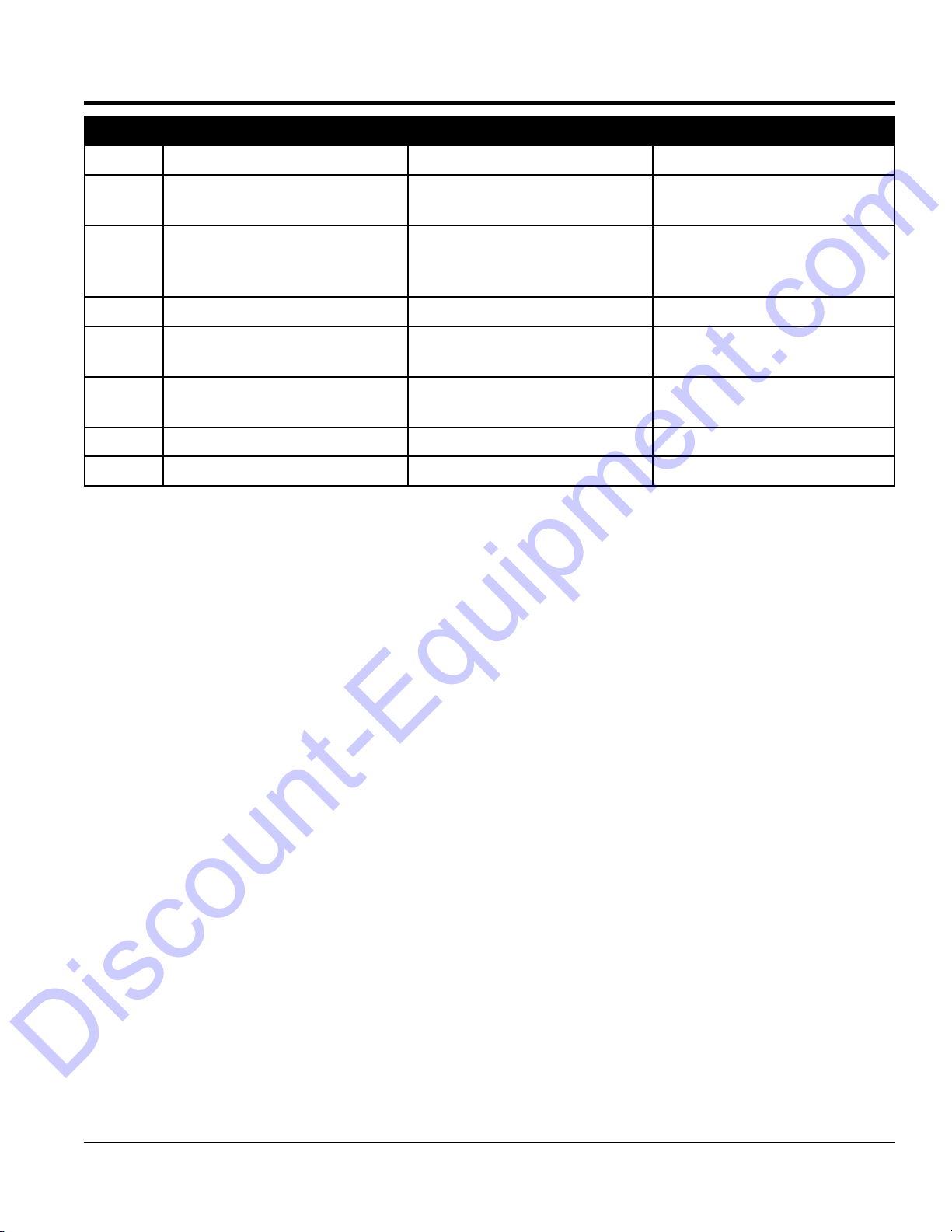
TRAINING CHECKLIST
Discount-Equipment.com
Training Checklist
No, Description OK? Date
1
2
3 Fuel system, refueling procedure.
4
5
6 Emergency stop procedures.
7 Machine transport and storage.
Read operation manual
completely.
Machine layout, location of
components, checking of engine
oil levels.
Operation of controls (machine
not running).
Safety controls, safety stop switch
operation.
MC12PH CONCRETE MIXER • OPERATION AND PARTS MANUAL — REV. #1 (09/02/15) — PAGE 5
Page 7
SAFETY INFORMATION
Do not operate or service the equipment before reading
the entire manual. Safety precautions should be followed
at all times when operating this equipment.
Failure to read and understand the safety
messages and operating instructions could
result in injury to yourself and others.
SAFETY MESSAGES
The four safety messages shown below will inform you
about potential hazards that could injure you or others. The
safety messages specifi cally address the level of exposure
to the operator and are preceded by one of four words:
DANGER, WARNING, CAUTION
SAFETY SYMBOLS
Potential hazards associated with the operation of this
equipment will be referenced with hazard symbols which
may appear throughout this manual in conjunction with
Discount-Equipment.com
safety messages.
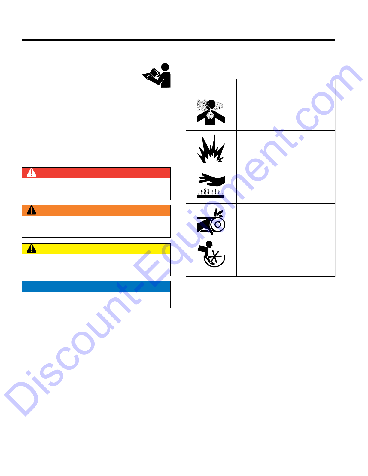
DANGER
Indicates a hazardous situation which, if not avoided,
WILL result in DEATH or SERIOUS INJURY.
WARNING
Indicates a hazardous situation which, if not avoided,
COULD result in DEATH or SERIOUS INJURY.
CAUTION
Indicates a hazardous situation which, if not avoided,
COULD result in MINOR or MODERATE INJURY.
or NOTICE.
Symbol Safety Hazard
Lethal exhaust gas hazards
Explosive fuel hazards
Burn hazards
Rotating parts hazards
NOTICE
Addresses practices not related to personal injury.
PAGE 6 — MC12PH CONCRETE MIXER • OPERATION AND PARTS MANUAL — REV. #1 (09/02/15)
Page 8
GENERAL SAFETY
NOTICE
This equipment should only be operated by trained and
Whenever necessary, replace nameplate, operation and
Manufacturer does not assume responsibility for any
accident due to equipment modifi cations. Unauthorized
use accessories or attachments that are not
recommended by Multiquip for this equipment. Damage
keep
Also, know the phone numbers
fi re department.
This information will be invaluable in the case of an
Discount-Equipment.com
SAFETY INFORMATION
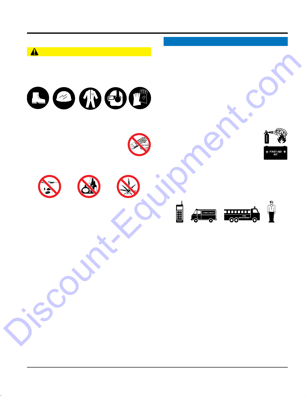
CAUTION
NEVER operate this equipment without proper protective
clothing, shatterproof glasses, respiratory protection,
hearing protection, steel-toed boots and other protective
devices required by the job or city and state regulations.
Avoid wearing jewelry or loose fi tting clothes that may
snag on the controls or moving parts as this can cause
serious injury.
NEVER operate this equipment when not
feeling well due to fatigue, illness or when
under medication.
NEVER operate this equipment under the
infl uence of drugs or alcohol.
ALWAYS clear the work area of any debris, tools, etc.
that would constitute a hazard while the equipment is
in operation.
ALWAYS check the equipment for loosened threads or
bolts before starting.
DO NOT use the equipment for any purpose other than
its intended purposes or applications.
qualifi ed personnel 18 years of age and older.
safety decals when they become diffi cult read.
equipment modifi cation will void all warranties.
NEVER
to the equipment and/or injury to user may result.
ALWAYS know the location of the nearest
fi re extinguisher.
ALWAYS know the location of the nearest
fi rst aid kit.
ALWAYS know the location of the nearest phone or
a phone on the job site.
of the nearest ambulance, doctor and
emergency.
MC12PH CONCRETE MIXER • OPERATION AND PARTS MANUAL — REV. #1 (09/02/15) — PAGE 7
Page 9

SAFETY INFORMATION
MIXER SAFETY
ENGINE SAFETY (GASOLINE MODELS ONLY)
Engine fuel exhaust gases contain poisonous carbon
monoxide. This gas is colorless and odorless, and can
The engine of this equipment requires an adequate
operate this equipment
place hands or fingers inside engine
operate the engine with heat shields or
while the engine is hot. Hot oil will gush out of the oil
tank and severely scald any persons in the general area
Make certain the operator knows how to and is capable
run engine without an air fi lter or with a dirty air
fi lter. Severe engine damage may occur. Service air fi lter
Discount-Equipment.com
DANGER
NEVER operate the equipment in an explosive
atmosphere or near combustible materials. An
explosion or fi re could result causing severe
bodily harm or even death.
DO NOT mix fl ammable or explosive substances.
WARNING
NEVER place your hands inside the drum
while starting or operating this equipment.
NEVER disconnect any emergency
or safety devices. These devices are
intended for operator safety. Disconnection of these
devices can cause severe injury, bodily harm or even
death. Disconnection of any of these devices will void
all warranties.
Before operating mixer, ensure that safety grate is in
position and correctly fi tted.
CAUTION
NEVER lubricate components or attempt service on a
running machine.
NOTICE
DANGER
cause death if inhaled.
free fl ow of cooling air. NEVER
in any enclosed or narrow
area where free fl ow of the
air is restricted. If the air
fl ow is restricted it will cause
injury to people and property
and serious damage to the
equipment or engine.
WARNING
DO NOT
compartment when engine is running.
NEVER
guards removed.
Keep fi ngers, hands hair and clothing away
from all moving parts to prevent injury.
DO NOT remove the engine oil drain plug
DANGEROUS
GAS FUMES
ALWAYS keep the machine in proper running condition.
ALWAYS ensure mixer is on level ground before mixing.
Fix damage to machine and replace any broken parts
immediately.
DO NOT tip mixer onto drum mouth when the drum is
rotating.
Ensure the drum is rotating while fi lling and emptying
the drum.
ALWAYS store equipment properly when it is not being
used. Equipment should be stored in a clean, dry location
out of the reach of children and unauthorized personnel.
PAGE 8 — MC12PH CONCRETE MIXER • OPERATION AND PARTS MANUAL — REV. #1 (09/02/15)
of the mixer.
CAUTION
NEVER touch the hot exhaust manifold,
muffl er or cylinder. Allow these parts to cool
before servicing equipment.
of turning the engine OFF in case of an emergency.
NOTICE
NEVER
frequently to prevent engine malfunction.
NEVER tamper with the factory settings
of the engine or engine governor. Damage
to the engine or equipment can result
if operating in speed ranges above the
maximum allowable.
Page 10
SAFETY INFORMATION
FUEL SAFETY (GASOLINE MODELS ONLY)
GENERATOR SAFETY
If using a generator to power mixer, refer to
applicable generator manual safety information
section.
ELECTRIC MOTOR SAFETY
(ELECTRIC MODELS ONLY)
Power Cord/Cable Safety
cables or cords when
connecting equipment to generator. Inspect for cuts in
Make sure power cables are securely connected.
Incorrect connections may cause electrical shock and
Ensure that cables and cords will not be tripped over or
make certain that proper power or extension
allow any person or animal to stand underneath
make sure forklift forks are inserted into pockets
Tighten fuel tank cap securely and close fuel cock to
tie down equipment during transport by
tip the engine to extreme angles during lifting as
it may cause oil to gravitate into the cylinder head, making
Discount-Equipment.com
DANGER
DO NOT start the engine near spilled fuel or combustible
fl uids. Fuel is extremely fl ammable and its vapors can
cause an explosion if ignited.
ALWAYS refuel in a well-ventilated area, away from
sparks and open fl ames.
ALWAYS use extreme caution when working with
fl ammable liquids.
DO NOT fi ll the fuel tank while the engine is running
or hot.
DO NOT overfi ll tank, since spilled fuel could ignite if it
comes into contact with hot engine parts or sparks from
the ignition system.
Store fuel in appropriate containers, in well-ventilated
areas and away from sparks and fl ames.
NEVER use fuel as a cleaning agent.
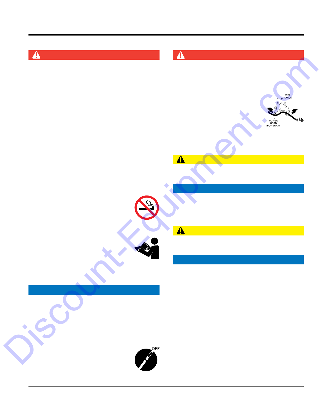
DO NOT smoke around or near the
equipment. Fire or explosion could result
from fuel vapors or if fuel is spilled on a
hot engine.
DANGER
NEVER let power cords or cables lay in water.
NEVER use damaged or worn
the insulation.
NEVER grab or touch a live power
cord or cable with wet hands. The
possibility exists of electrical shock,
electrocution or death.
damage to the mixer.
CAUTION
trapped underneath the mixer.
NOTICE
ALWAYS
cord has been selected for the job.
TRANSPORTING SAFETY
CAUTION
NEVER
the equipment while lifting.
NOTICE
Operate electric motor only at the specifi ed voltage
indicated on the nameplate.
DO NOT spray water onto electric motor.
ALWAYS disconnect AC power plug from power source
before moving mixer.
ALWAYS make sure the ON/OFF switch
on the electric motor is in the OFF position
when not in use and before inserting the
mixer’s power plug into an AC receptacle.
MC12PH CONCRETE MIXER • OPERATION AND PARTS MANUAL — REV. #1 (09/02/15) — PAGE 9
NOTICE
ALWAYS
(if applicable) as far as possible when lifting the mixer.
ALWAYS shutdown engine before transporting.
NEVER lift the equipment while the engine is running.
prevent fuel from spilling.
DO NOT lift machine to unnecessary heights.
ALWAYS
securing the equipment with rope.
NEVER
the engine start diffi cult.
Page 11
SAFETY INFORMATION
TOWING SAFETY
ENVIRONMENTAL SAFETY/DECOMMISSIONING
Decommissioning is a controlled process used to safely
retire a piece of equipment that is no longer serviceable.
If the equipment poses an unacceptable and unrepairable
safety risk due to wear or damage or is no longer cost
effective to maintain (beyond life-cycle reliability) and is to
be decommissioned (demolition and dismantlement),be
pour waste or oil directly onto the ground, down
When the life cycle of this equipment is over, remove
battery if equipped and bring to appropriate facility for
lead reclamation. Use safety precautions when handling
When the life cycle of this equipment is over, it is
recommended that the mixer frame and all other metal
Metal recycling involves the collection of metal from
discarded products and its transformation into raw
materials to use in manufacturing a new product.
Recyclers and manufacturers alike promote the process
of recycling metal. Using a metal recycling center
Discount-Equipment.com
CAUTION
Check with your local county or state safety towing
regulations, in addition to meeting Department of
Transportation (DOT) Safety Towing Regulations,
before towing your mixer.
In order to reduce the possibility of an accident while
transporting the mixer on public roads, ALWAYS make
sure the towing vehicle is mechanically sound and in
good operating condition.
ALWAYS shutdown engine before transporting.
ALWAYS inspect the hitch and coupling for wear. NEVER
tow a mixer with defective hitches, couplings, chains, etc.
Check the tire air pressure on both towing vehicle and
mixer Mixer tires should be infl ated to 50 psi cold. Also
check the tire tread wear on the vehicle and mixer.
ALWAYS make sure the mixer is equipped with a safety
chain.
ALWAYS properly attach mixer’s safety chains to towing
vehicle.
The maximum speed for highway towing is 55 MPH unless
posted otherwise. Recommended off-road towing is not to
exceed 15 MPH or less depending on type of terrain.
Avoid sudden stops and starts. This can cause skidding,
or jack-knifi ng. Smooth, gradual starts and stops will
improve towing.
Avoid sharp turns to prevent rolling.
Mixer should be adjusted to a level position at all times
when towing.
NOTICE
sure to follow rules below.
DO NOT
a drain or into any water source.
Contact your country's Department of
Public Works or recycling agency in your
area and arrange for proper disposal of
any electrical components, waste or oil
associated with this equipment.
batteries that contain sulfuric acid.
parts be sent to a recycling center.
promotes energy cost savings.
Raise and lock mixer wheel stand in up position when
towing.
Place chock blocks underneath wheel to prevent rolling
while parked.
PAGE 10 — MC12PH CONCRETE MIXER • OPERATION AND PARTS MANUAL — REV. #1 (09/02/15)
Page 12

EMISSIONS INFORMATION
NOTICE
The gasoline engine used in this equipment has been
designed to reduce harmful levels of carbon monoxide
(CO), hydrocarbons (HC) and nitrogen oxides (NOx)
contained in gasoline exhaust emissions.
This engine has been certifi ed to meet US EPA Evaporative
emissions requirements in the installed confi guration.
Attempting to modify or make adjustments to the engine
emmission system by unauthorized personnel without
proper training could damage the equipment or create an
unsafe condition.
Additionally, modifying the fuel system may adversely affect
evaporative emissions, resulting in fi nes or other penalties.
Emission Control Label
The emission control label is an integral part of the emission
system and is strictly controlled by regulation(s).
The label must remain with the engine for its entire life.
If a replacement emission label is needed, please contact
your authorized engine distributor.
Discount-Equipment.com
SAFETY INFORMATION
MC12PH CONCRETE MIXER • OPERATION AND PARTS MANUAL — REV. #1 (09/02/15) — PAGE 11
Page 13
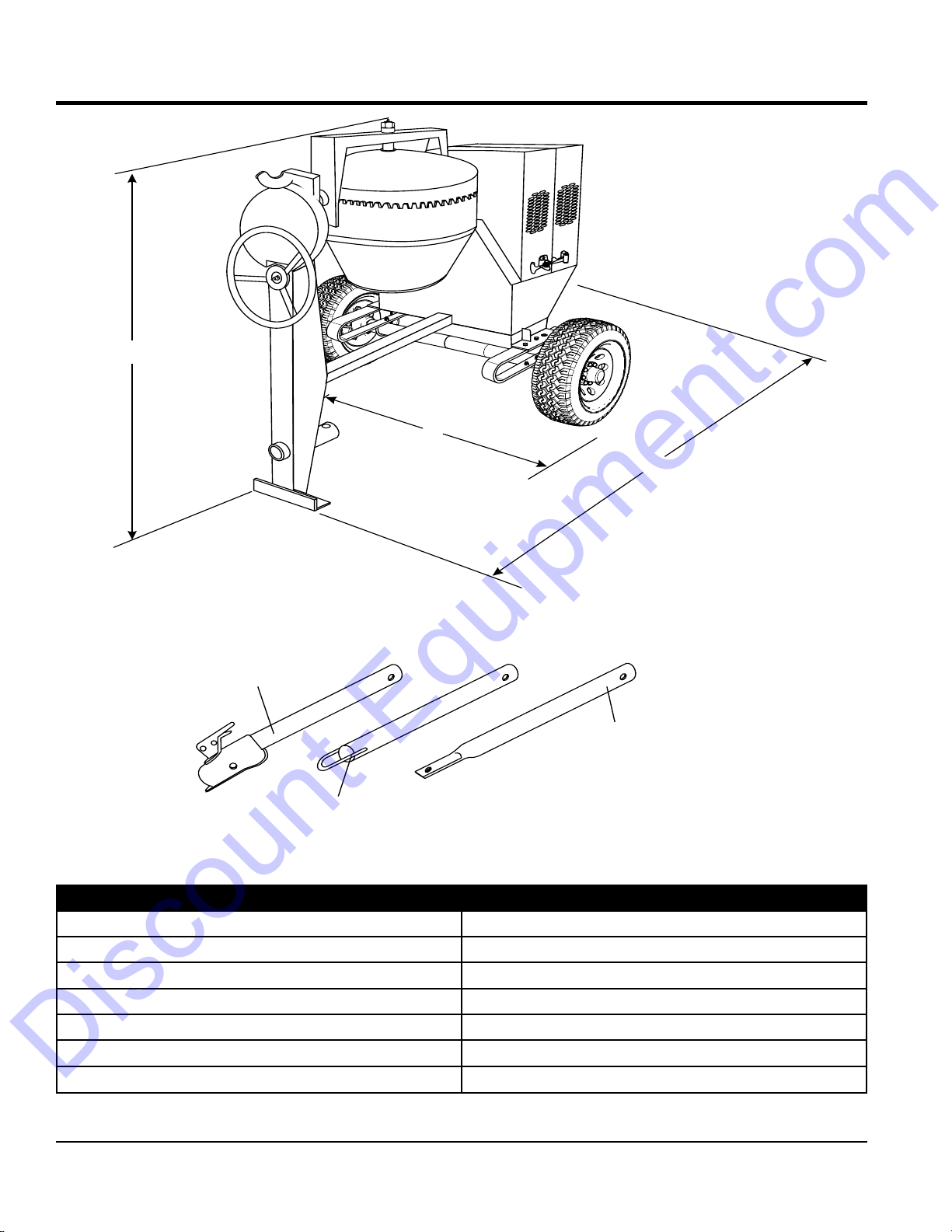
SPECIFICATIONS/DIMENSIONS
A
OPTIONAL TOW BARS
HBC-1
2-INCH
BALL COUPLER
HLC-1
LOOP COUPLER
HPC-1
1-INCH
PIN COUPLER
B
C
Discount-Equipment.com
Figure 1. Dimensions
Table 1. MC12PH Concrete Mixer Specifications
Height (A) 67.5 in. (1,460.5 mm)
Width (B) 56 in. (1,422.4 mm)
Length (C) 83 in. (2,108.2 mm)
Maximum Mixing Capacity 12 cu. ft. (339.8 liters)
Drum Opening 20 in. (508 mm)
Bag Capacity
Weight
PAGE 12 — MC12PH CONCRETE MIXER • OPERATION AND PARTS MANUAL — REV. #1 (09/02/15)
1.5 ~ 2 bags
1,000 lbs. (543.59 Kg)
Page 14
ENGINE SPECIFICATIONS
Discount-Equipment.com
Table 2. MC12PH Noise
Model MC12PH
Guaranteed ISO 11201:2010 Based
Sound Pressure Level at Operator Station in dB(A)
NOTES:
1. Sound Pressure and Power Levels are “A” weighted Measures per ISO 226:2003 (ANSI S1.4-1981). They are measured with the operating
condition of the machine which generates the most repeatable but highest values of the sound levels. Under normal circumstances, the sound
level will vary depending on the condition of the material being worked upon..
TBD
Table 3. Engine Specifications/Dimensions
Model GX340UT2QA2/GX340UT2QAP2
Type
Bore X Stroke 3.2 in. X 2.5 in. (88 mm x 64 mm)
Displacement 389 cm
Max. Output 10.7 H.P. (7.9 kW) @ 3600 RPM
Continuous Rated Power
Max. Net Torque 26.4 Nm/2.69 kgfm/2,500 rpm
Ignition System Digital CDI with variable ignition timing
Fuel Tank Capacity 1.61 U.S. Gallons (Approx. 6.1 Liters)
Fuel Unleaded Gasoline
Lube Oil Capacity 1.06 qt. (1.1 liters)
Oil Type
Speed Control Method Centrifugal Flyweight Type
Cooling System Forced Air
Starting Method Recoil Start
Spark Plug Type BPR6ES NGK
Spark Plug Gap 0.028-0.031 in. (0.70 - 0.80 mm)
Dimension (L x W x H)
Dry Net Weight 69.9 lbs (31.7 Kg.)
Air cooled 4-stroke OHV petrol engine, 25° inclined
cylinder, horizontal shaft, cast iron sleeve
3
5.6 kW (7.5 HP)/3,000 rpm
6.3 kW (8.4 HP)/3,600 rpm
4-Stroke API, SF or SG
SAE 10W-30 General Use
16.0 x 18.1 X 17.6 in.
(406 X 460 X 448 mm)
MC12PH CONCRETE MIXER • OPERATION AND PARTS MANUAL — REV. #1 (09/02/15) — PAGE 13
Page 15
APPLICATION
Discount-Equipment.com
This mixer is intended only for the production of concrete.
The mixer must be used for its intended purpose and is
not suitable for the mixing of flammable or explosive
substances. The mixer must not be used in an explosive
atmosphere.
POWER PLANTS
The Multiquip MC12PH mixer is powered by a 10.7 HP,
air-cooled, 4-stroke gasoline engine. Refer to Table 3 to
for specific engine.
HARDWARE
Check all hardware on the mixer before starting. Periodically
inspect all hardware. Loose hardware can contribute
to early component failure and poor performance. Use
Table 4 as general guideline when the torqueing of mixer
hardware is required. Remember to keep all mixer hardware
components tight.
GENERAL INFORMATION
Table 4. Hardware Torque Recommendations
Hardware Diameter Torque (ft-lbs)
5/16-inch x 18 14
3/8-inch x 16 24
3/8-inch x 24 37
1/2-inch x 13 39
1/2-inch x 13 (Grade 8) 90
ENGINE MAINTENANCE
For basic engine maintenance, refer to the engine
maintenance section in this manual. For more detailed
engine maintenance, refer to the Honda Engine Owner's
manual furnished with the engine.
PAGE 14 — MC12PH CONCRETE MIXER • OPERATION AND PARTS MANUAL — REV. #1 (09/02/15)
Page 16
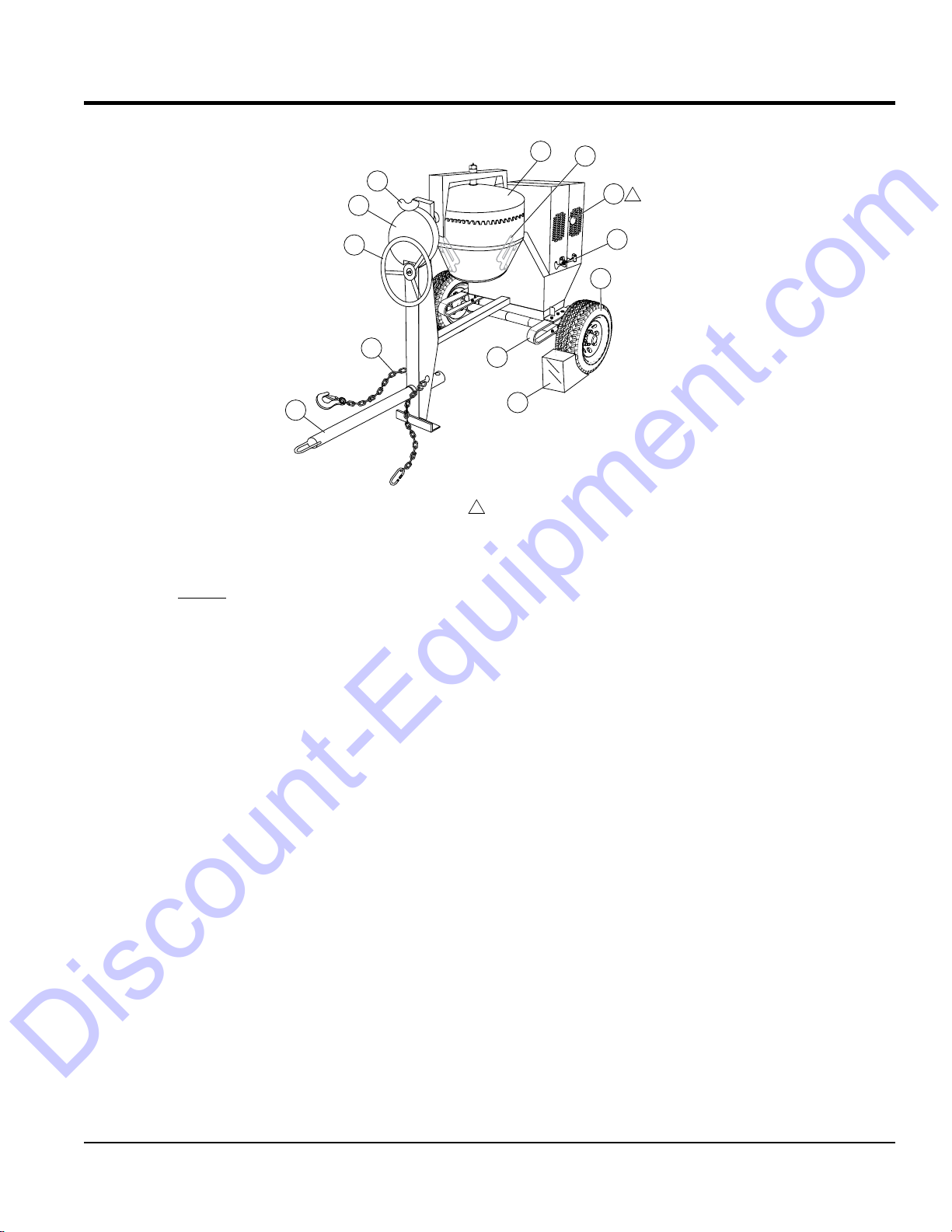
Figure 2. Mixer Major Components
Discount-Equipment.com
BASIC COMPONENTS
1
12
2
3
10
1
4
5
6
1. Plastic Mixing Drum — The Multiquip MC12PH uses
a 12 cu. ft plastic mixing drum. This drum is to be used
for mixing of concrete. Always clean the drum after
each use. DO NOT use this mixing drum for the mixing
of volatile or hot liquids.
2. Dump Latch — To rotate the mixing drum, this latch
must be in the up position. To lock the drum, place the
latch in the down position.
11
9
7
8
NOTE:
SHOWN FOR CLARITY
1
ACTUAL LOCATION IS ON OPPOSITE SIDE
7. Cantilever Suspension — This mixer uses a cantilever
type suspension. Check the mounting hardware for
bolt hole elongation and tightness. See maintenance
section of this manual for recommended maintenance.
8. Chock Blocks — Place these blocks (not included as
part of the mixer package) under each mixer wheel
to prevent rolling, when mixer is not connected to the
towing vehicle.
3. Dump Gear Guard — NEVER operate the mixer
with this guard removed. Its purpose is to prevent dirt
and debris from entering the dump gear. In addition
operator clothing could become entangled in the dump
gear, causing severe injury and bodily harm.
4. Handwheel — Turn this wheel clockwise or
counterclockwise to rotate the mixing drum. Remember
the dump latch must be in the up position in order for
the mixing drum to be rotated.
5. Safety Chain — This mixer uses a 3/16-inch thick, 72
inches long zinc-plated saftey chain. ALWAYS connect
the safety chain when towing.
9. Tires Ply — The tire ply (layers) number is rated in
letters. This mixer uses 13-inch 2-ply tires. Replace
with only recommended type tires.
10. ON/OFF Switch — This switch is located on the side
of the mixer frame. When activated it will shut down the
engine. Pull out when starting the engine.
11. Cabinet/Latch — Encloses engine and electric motor.
NEVER run mixer with cabinet removed. Use latches
to secure engine compartment cabinet.
12. Mixing Blades — Used for the mixing of concrete.
When blades show signs of wear, replace the blades.
6. Tow Bar — This mixer uses various towing bars, please
reference the frame assembly drawing and parts list
in this manual to determine which tow bar meets your
requirements.
MC12PH CONCRETE MIXER • OPERATION AND PARTS MANUAL — REV. #1 (09/02/15) — PAGE 15
Page 17
INITIAL SERVICING
Discount-Equipment.com
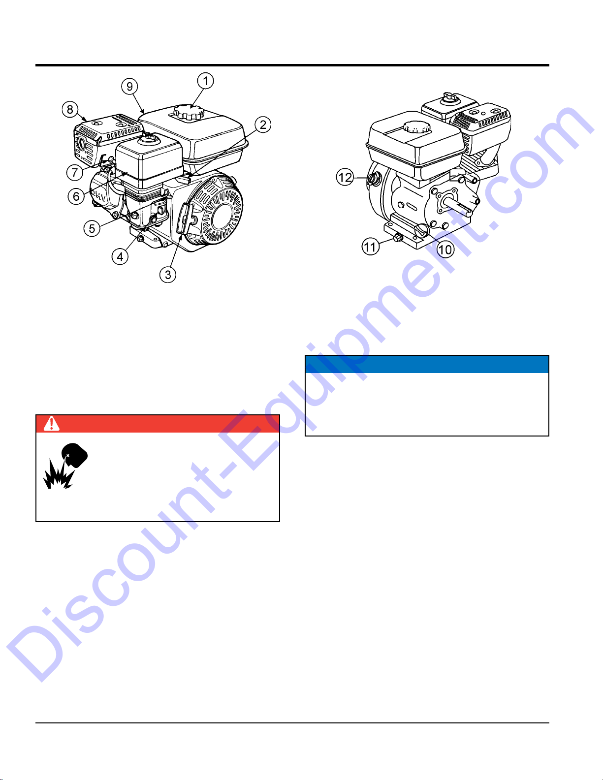
ENGINE COMPONENTS
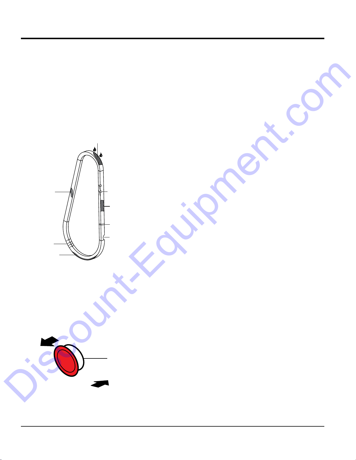
Figure 3. Engine Components
The engine (Figure 3) must be checked for proper
lubrication and filled with fuel prior to operation. Refer to the
manufacturer's engine manual for instructions and details
of operation and servicing.
1. Fuel Filler Cap – Remove this cap to add unleaded
gasoline to the fuel tank. Make sure cap is tightened
securely. DO NOT over fill.
DANGER
Add fuel to the tank only when the engine
is stopped and has had an opportunity to
cool down. In the event of a fuel spill, DO
NOT attempt to start the engine until the
fuel residue has been completely wiped up
and the area surrounding the engine is dry.
2. Throttle Lever – Used to adjust engine RPM speed.
This lever is connect to the throttle lever cable located
on the handle bars. Reference throttle cable installation
procedure in this manual.
3. Recoil Starter (pull rope) – Manual-starting method.
Pull the starter grip until resistance is felt, then pull
briskly and smoothly.
4. Fuel Valve Lever – OPEN to let fuel flow, CLOSE to
stop the flow of fuel.
5. Choke Lever – Used in the starting of a cold engine,
or in cold weather conditions. The choke enriches the
fuel mixture.
6. Air Cleaner – Prevents dirt and other debris from
entering the fuel system. Remove wing-nut on top of
air filter canister to gain access to filter element.
NOTICE
Operating the engine without an air filter, with a
damaged air filter, or a filter in need of replacement
will allow dirt to enter the engine, causing rapid engine
wear.
7. Spark Plug – Provides spark to the ignition system.
Set spark plug gap according to engine manufacturer's
instructions. Clean spark plug once a week.
8. Muffler – Used to reduce noise and emissions. NEVER
touch when hot!
9. Fuel Tank – Fill with unleaded gasoline. Refer to Table 3
for fuel tank capacity. For additional information refer
to Honda engine owner's manual.
10. Dipstick/Oil Filler Cap – Remove this cap to determine
if the engine oil is low. Add oil through this filler port as
recommended in Table 5.
11. Oil Drain Plug – Remove this plug to remove oil from
the engine's crankcase.
12. Engine ON/OFF Switch – ON position permits engine
starting, OFF position stops engine operation.
PAGE 16 — MC12PH CONCRETE MIXER • OPERATION AND PARTS MANUAL — REV. #1 (09/02/15)
Page 18
TOWING GUIDELINES
Discount-Equipment.com
TOWING SAFETY PRECAUTIONS
CAUTION
Check with your county or state safety towing
regulations department before towing your
mixer.
To reduce the possibility of an accident while
transporting the mixer on public roads, always make
sure that the mixer towing components and the towing
vehicle are in good operating condition and both units
are mechanically sound.
The following list of suggestions should be used when
towing the mixer:
Make sure that the hitch and coupling of the towing
vehicle are rated equal to, or greater than the trailer
"gross vehicle weight rating" (GVWR).
ALWAYS inspect the hitch and coupling for wear. NEVER
tow the mixer with defective hitches, couplings, chains
etc.
CHECK the tire air pressure on both the towing vehicle
and the trailer. Also check the tire tread wear on both
vehicles.
ALWAYS make sure the mixer is equipped with a "Safety
Chain."
ALWAYS attach trailer's safety chain to the frame of
towing vehicle.
ALWAYS make sure that the towing vehicle's directional,
backup, and brake lights are working properly.
Remember in most cases the maximum speed unless
otherwise posted for highway towing is 45 MPH, however
before towing your mixer, check your local state, and
county vehicle towing requirements. Recommended offroad towing is not to exceed 10 MPH or less depending
on type of terrain.
Place chocked blocks underneath wheels to prevent
rolling
vehicle.
Inflate tires to correct pressure, inspect tires for cuts, and
excessive wear. See Table 16 (Tire Wear Troubleshooting).
When towing of the mixer is required, place the drum in
the up position (mouth facing upwards).
, while parked, if disconnected from towing
ALWAYS make sure that the fuel valve lever is in the
OFF position (gasoline models only).
Check wheel mounting lug nuts with a torque wrench.
Torque wheel lug nuts as described in the maintenance
section of this manual.
Check tightness of U-clamp nuts, torque suspension
hardware as referenced in the maintenance section of
this manual.
Avoid sudden stops and starts. This can cause skidding,
or jackknifing. Smooth, gradual starts and stops will
improve gas milage.
Avoid sharp turns to prevent rolling.
CAUTION
If the mixer tow bar is deformed or damaged replace
entire tow bar. NEVER tow the mixer with a defective
tow bar. There exist the possibility of the trailer
separating from the towing vehicle.
TOW BAR TO VEHICLE (COUPLER ONLY)
1. Check the vehicle hitch ball, and mixer's coupler for
signs of wear or damage. Replace any parts that are
worn or damaged before towing.
2. Use only a 2-inch ball diameter (towing vehicle), this will
match the mixer's 2-inch coupler. Use of any other ball
diameter will create an extremely dangerous condition
which can result in separation of the coupler and ball
or ball failure.
3. After tow bar has been connected to mixer (see next
page), attach mixer's coupler to the hitch ball on the
towing vehicle securely and make sure the lock lever
is in the down position (locked).
MIXER TOW BAR VEHICLE (PINTLE AND LOOP)
1. Make sure the bumper on the towing vehicle is
equipped to handle either a pintle or loop type tow
bar configuration.
2. After tow bar has been connected to mixer (see next
page), secure either type of tow bar to the towing
vehicle, following state and county towing regulations
3. As a minimum, use a 1/2-inch bolt and nylock nut grade
5 when securing either tow bar to the towing vehicle.
MC12PH CONCRETE MIXER • OPERATION AND PARTS MANUAL — REV. #1 (09/02/15) — PAGE 17
Page 19
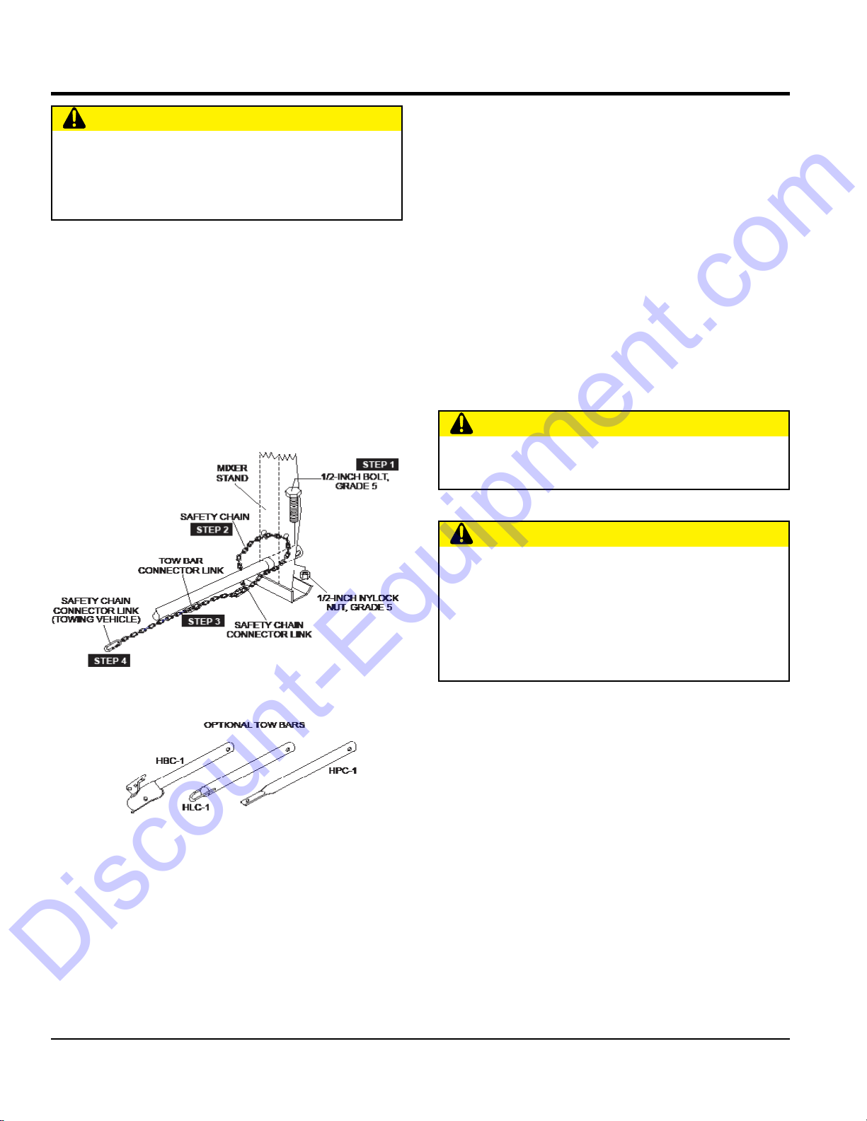
TOW BAR TO MIXER CONNECTION
Reference Figure A for the installation of the safety chain.
1.
Align the hole on the tow bar with the hole on the mixer
2. Route the safety chain through the holes just above
Extend the safety chain along the length of the tow bar,
looping it through the tow bar's connector link. Remove
Connect the free end of (connector link) the safety
chain to the towing vehicle. Remember it is critical
that the length of the chain be properly adjusted, to
prevent the draw bar and the front of the mixer stand
from dropping to the the ground (contact) in the event
the draw bar becomes disconnected from the towing
SAFETY CHAIN CONNECTION
Discount-Equipment.com
CAUTION
NEVER tow the mixer with the safety chain removed.
The safety chain is intended to prevent complete
separation of the mixer from the towing vehicle in the
event of a tow bar failure.
Insert the tow bar through the round opening at the
bottom of the mixer stand.
frame, and insert 1/2-inch bolt through tow bar and
frame. Secure tow bar to frame with 1/2-inch nylock
nut. Tighten to 40 ft.-lbs.
the tow bar, located on each side of the mixer stand.
Loop the chain together and place under the tow bar.
Secure the loop with the connector link.
3.
any excess chain slack.
4.
vehicle.
CAUTION
DO NOT tow or lift the mixer unless the mixing drum
is completely empty.
Figure A. Tow Bar and Safety Chain Installation
CAUTION
Use a lifting device to lift tow bar onto vehicle coupler. If
lifting device is not available, have 2 persons of similar
height lift the tow bar. When lifting, do not attempt to lift
by bending forward. Bend hips and knees to squat down
to your load, keep it close to your body, and straighten
your legs to lift.
PAGE 18 — MC12PH CONCRETE MIXER • OPERATION AND PARTS MANUAL — REV. #1 (09/02/15)
Page 20
UPPER LIMIT
LOWER LIMIT
INSPECTION
Discount-Equipment.com
BEFORE STARTING
1. Read all safety instructions at the beginning of manual.
2. Clean the unit, removing dirt and dust, particularly the
engine cooling air inlet, carburetor and air cleaner.
3. Check the air filter for dirt and dust. If air filter is dirty,
replace air filter with a new one as required.
4. Check carburetor for external dirt and dust. Clean with
dry compressed air.
5. Check fastening nuts and bolts for tightness.
CAUTION
ALWAYS wear approved eye and hearing
protection while operating the mixer.
CAUTION
NEVER place hands or feet inside the
engine guard cover while the engine is
running. ALWAYS shut the engine down
before performing any kind of maintenance
service on the mixer.
5. I
NOTICE
Reference engine manufacturer’s manual for specific
servicing instructions.
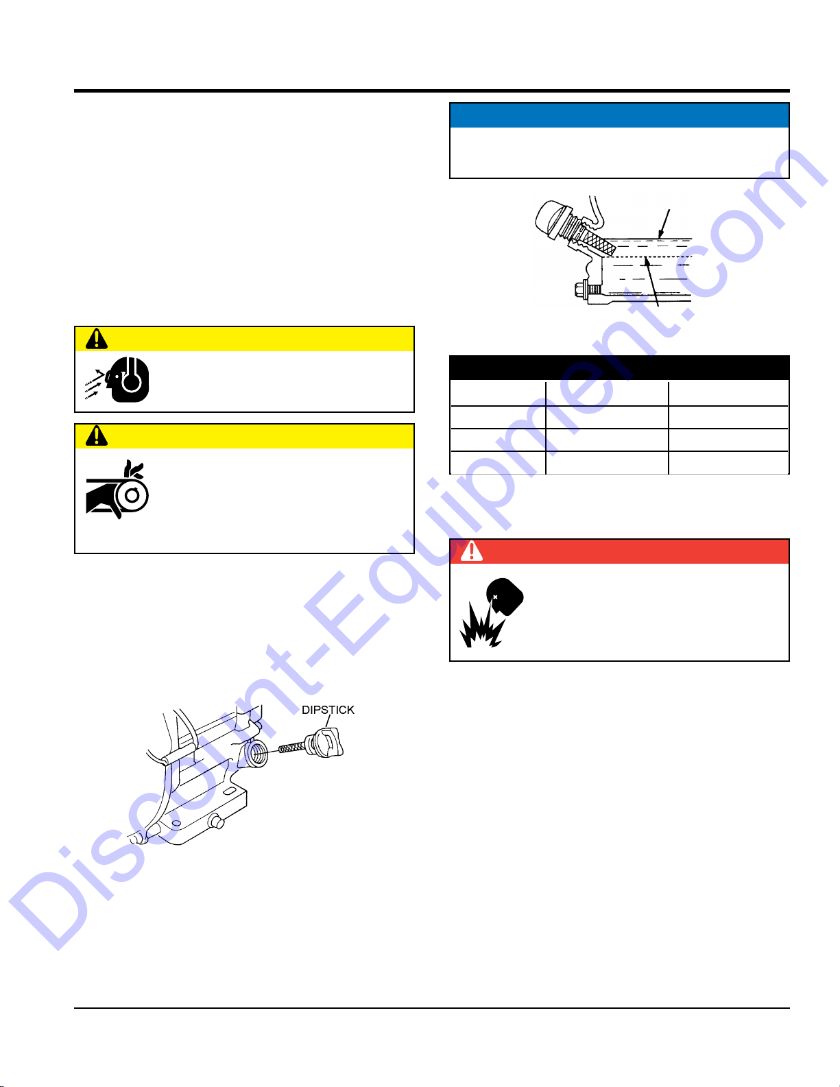
Figure 5. Engine Oil Dipstick (Oil Level)
Table 5. Oil Type
Season Temperature Oil Type
Summer 25°C or Higher SAE 10W-30
Spring/Fall 25°C ~ 10°C SAE 10W-30/20
Winter 0°C or Lower SAE 10W-10
FUEL CHECK
DANGER
ENGINE OIL CHECK
1. To check the engine oil level, place the unit on secure
level ground with the engine stopped.
2. Remove the filler dipstick from the engine oil filler hole
(Figure 4) and wipe it clean.
Figure 4. Engine Oil Dipstick (Removal)
3. Insert and remove the dipstick without screwing it into
the filler neck. Check the oil level shown on the dipstick.
4. If the oil level is low (Figure 5), fill to the edge of the
oil filler hole with the recommended oil type (Table 5).
Maximum oil capacity is 2.33 pints (1.09 liters).
Motor fuels are highly flammable and can be
dangerous if mishandled. DO NOT smoke
while refueling. DO NOT attempt to refuel the
mixer if the engine is hot or running.
1. Remove the gasoline cap located on top of fuel tank.
2. Visually inspect to see if fuel level is low. If fuel is low,
replenish with unleaded fuel.
3. When refueling, be sure to use a strainer for filtration.
DO NOT top-off fuel. Wipe up any spilled fuel
immediately.
BLADE CHECK
Check for worn blades.
If using a plastic drum, replace the blades using the part
numbers referenced in the parts section of this manual.
MC12PH CONCRETE MIXER • OPERATION AND PARTS MANUAL — REV. #1 (09/02/15) — PAGE 19
Page 21
V-BELT CHECK
OIL SOAKED
MISSING RUBBER
PULL OUT
TO STOP ENGINE
Discount-Equipment.com
Visually examine the V-belt (Figure 6) and determine if it
is full of tiny cracks, frayed, has pieces of rubber missing,
is peeling or otherwise damaged.
Also, examine the belt and determine if it is oil soaked or
"glazed " (hard shiny appearance on the sides of the belt).
Either of these two conditions can cause the belt to run hot,
which can weaken it and increase the danger of it breaking.
If the V-belt exhibits any of the above wear conditions
replace the V-belt immediately.
INSPECTION
GLAZED
CRACKS
SIDEWALL
WEAR
Figure 6. V-Belt Inspection
CORD FAILURE
WORN BACK
COVER
BROKEN
START/STOP SWITCH
This unit has been equipped with a start/stop switch
(Figure 7), which should be tested every time the unit is
started.
TO START ENGINE
START/STOP
SWITCH
PAGE 20 — MC12PH CONCRETE MIXER • OPERATION AND PARTS MANUAL — REV. #1 (09/02/15)
PUSH IN
Figure 7. Start/Stop Switch
Page 22
START-UP
Discount-Equipment.com
This section is intended to assist the operator with the initial
start-up of the unit. It is extremely important that
this section be read carefully before attempting
to use the mixer in the field. DO NOT use your
mixer until this section is thoroughly understood.
WARNING
Failure to understand the operation of the mixer could
result in severe damage to the mixer or personal injury.
Reference Figure 2 for the location of any components
referenced in this manual.
CAUTION
NEVER operate the mixer in a confined
area or enclosed area structure that does
not provide ample free flow of air.
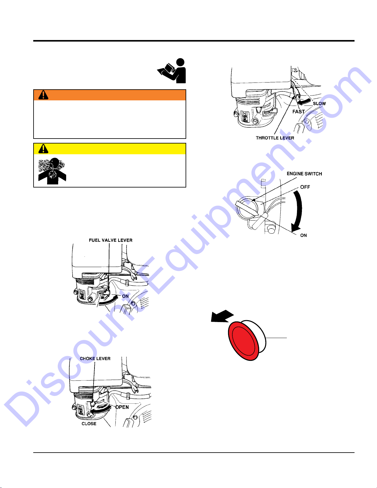
The following steps outline the procedure for starting the
engine.
1. Move the fuel shut-off lever (Figure 8) to the ON
position.
3. Move the throttle lever (Figure 10) away from the slow
position, about 1/3 of the way toward the fast position.
Figure 10. Throttle Lever
4. Turn the engine switch (Figure 11) to the ON position.
Figure 8. Fuel Shut-Off Lever
2. To start a cold engine, move the choke lever (Figure
9) to the CLOSED position.
Figure 11. Engine On/Off Switch
5. Located at the rear of the mixer frame is the main
start/ stop button (Figure 12). Pull this button outward
to start the engine.
PULL OUT
TO START ENGINE
START/STOP
SWITCH
Figure 12. Engine Start/Stop Button
Figure 9. Choke Lever
MC12PH CONCRETE MIXER • OPERATION AND PARTS MANUAL — REV. #1 (09/02/15) — PAGE 21
Page 23
START-UP/OPERATION
Discount-Equipment.com
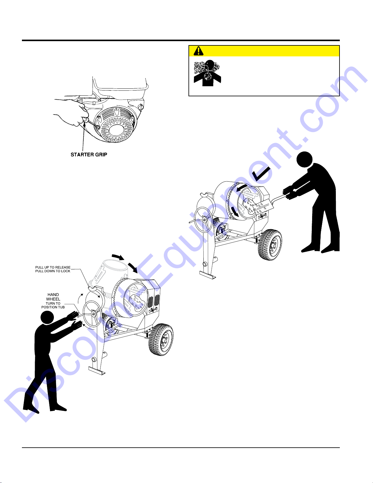
6. Pull the starter grip (Figure 13) lightly until you feel
resistance, then pull briskly. Return the starter grip
gently.
Figure 13. Starter Grip
OPERATION
1. To position the drum, make sure the mixer is placed
on firm level ground, then pull up on the dump latch
(Figure 14) and turn the hand wheel until the drum is
at the desired position. Once the drum is at the desired
position, pull down on the dump latch to lock the drum
in position.
CAUTION
NEVER stand in front or behind the mixing
drum while it is being placed in the dump
position. Stay clear of the mixing drum
while it is being positioned.
2. As the drum rotates, use a shovel (Figure 15) to place
the cement mix inside the drum, add water as required.
Be careful to only place the tip of the shovel inside
the drum.
Figure 15. Filling Mix Drum
Figure 14. Mixing Drum Positioning
PAGE 22 — MC12PH CONCRETE MIXER • OPERATION AND PARTS MANUAL — REV. #1 (09/02/15)
Page 24
OPERATION
Discount-Equipment.com
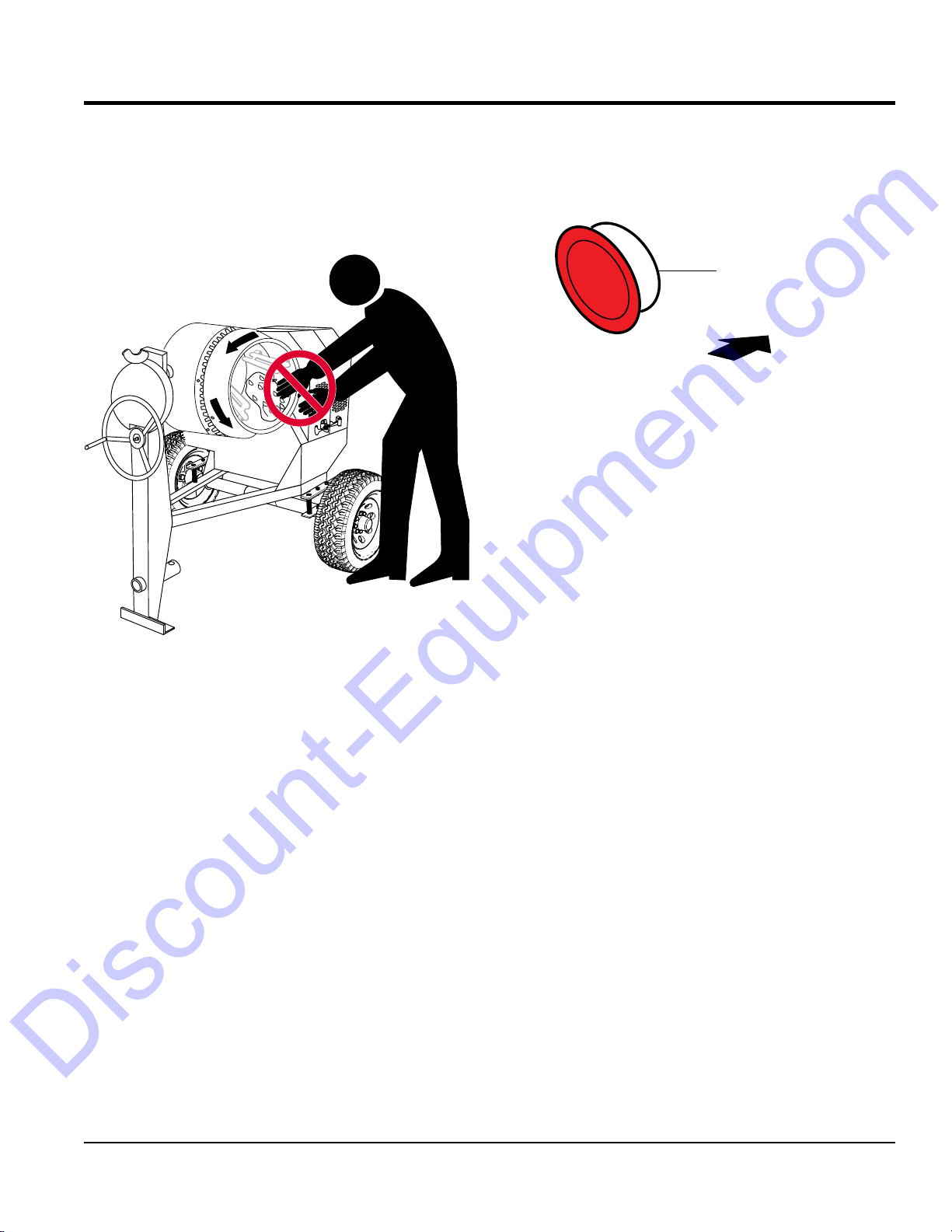
3. Placing the shovel all the way inside the drum
(Figure 16) will cause the shovel to strike the blades.
This condition will make the shovel rotate, and could
cause injury to personnel. NEVER place hands inside
the mixing drum while it is rotating.
STOPPING THE MIXER
1. Push the main start/stop switch (Figure 17) inward to
stop the engine.
START/STOP
SWITCH
PUSH IN
TO STOP ENGINE
Figure 17. Start/Stop Button (Stop Position)
2. Place fuel shut-off lever in the OFF position.
3. Clean drum of all debris and foreign matter.
Figure 16. Filling Mixing Drum
MC12PH CONCRETE MIXER • OPERATION AND PARTS MANUAL — REV. #1 (09/02/15) — PAGE 23
Page 25

MAINTENANCE (ENGINE)
Discount-Equipment.com
Use Table 6 as a general maintenance guideline when servicing your engine. For more detail engine maintenance information,
refer to the engine owner’s manual supplied with your engine.
Table 6. Engine Maintenance Schedule
DESCRIPTION
(3)
Engine Oil
Air Cleaner
All Nuts and
Bolts
Spark Plugs
Cooling Fins Check X
Spark Arrester Clean X
Fuel Tank Clean X
Fuel Filter Check X
Idle Speed
OPERATION BEFORE
Check X
Change X
Check X
Change X (1)
Re-tighten if
necessary
Check/Clean X
Replace X
Check/
Adjust
X
FIRST
MONTH OR
10 HRS.
EVERY 3
MONTHS
OR 25 HRS.
EVERY 6
MONTHS
OR 50 HRS.
EVERY
YEAR
OR 100
HRS.
X (2)
EVERY 2
YEARS OR
200 HRS.
Valve
Clearance
Fuel Lines Check Every 2 years (replace if necessary) (2)
(1) Service more frequently when used in DUSTY areas.
(2) These items should be serviced by your service dealer, unless you have the proper tools and are mechanically
proficient. Refer to the HONDA Shop Manual for service procedures.
(3) For commercial use, log hours of operation to determine proper maintenance intervals.
Check/
Adjust
X (2)
PAGE 24 — MC12PH CONCRETE MIXER • OPERATION AND PARTS MANUAL — REV. #1 (09/02/15)
Page 26

MAINTENANCE
0.024-0.028 IN.
GAP
OIL FILLER CAP
BOLT
Discount-Equipment.com
Perform the scheduled maintenance procedures as defined
by Table 6 and below:
DAILY
MAINTENANCE (ENGINE)
DIPSTICK
Thoroughly remove dirt and oil from the engine and
control area. Clean or replace the air cleaner elements
as necessary. Check and retighten all fasteners as
necessary. Check the gearbox for oil leaks. Repair or
replace as needed.
WEEKLY
Remove the fuel filter cap and clean the inside of the
fuel tank.
Remove or clean the filter at the bottom of the tank.
Remove and clean the spark plug (Figure 18), then adjust
the spark gap to 0.024 ~0.028 inch (0.6~0.7 mm). This
unit has electronic ignition, which requires no adjustments.
(0.6-0.7 MM.)
DRAIN
Figure 19. Engine Oil (Draining)
SEALING
WASHER
ENGINE AIR CLEANER
1. Remove the air cleaner cover and foam filter element
as shown in Figure 20.
2. Tap the paper filter element (Figure 20) several times
on a hard surface to remove dirt, or blow compressed
air [not exceeding 30 psi (207 kPa, 2.1 kgf/cm2)]
through the filter element from the air cleaner case
side. NEVER brush off dirt. Brushing will force dirt
into the fibers. Replace the paper filter element if it is
excessively dirty.
3. Clean foam element in warm, soapy water or
nonflammable solvent. Rinse and dry thoroughly. Dip
the element in clean engine oil and completely squeeze
out the excess oil from the element before installing.
DANGER
Figure 18. Spark Plug Gap
ENGINE OIL
1. Drain the engine oil when the oil is warm as shown in
Figure 19.
2. Remove the oil drain bolt and sealing washer and allow
the oil to drain into a suitable container.
3. Replace engine oil with recommended type oil as
listed in Table 5. For engine oil capacity, see Table 3
(Engine Specifications). DO NOT overfill.
4. Install drain bolt with sealing washer and tighten
securely.
MC12PH CONCRETE MIXER • OPERATION AND PARTS MANUAL — REV. #1 (09/02/15) — PAGE 25
DO NOT use gasoline as a cleaning solvent to avoid
creating the risk of fire or an explosion.
Figure 20. Engine Air Cleaner
Page 27

MAINTENANCE (ENGINE)
Discount-Equipment.com
BALL SOCKET AND CLAMP FACE MAINTENANCE
1. If the towing vehicle is equipped with a ball socket,
smear socket periodically with multi-purpose grease.
This will keep the ball socket well lubricated.
2. Periodically oil pivot points and clamp face surfaces
of coupler with SAE 30 WT. motor oil.
3. When parking or storing your mixer. Keep the coupler
off the ground so dirt will not build up in the ball socket.
GREASE FITTINGS (ZERK) MAINTENANCE
(MIXER)
There are grease fittings (Figure 21) that will require
lubrication. Lubricate these fittings once a month. Use
lithium base grease, grade N0.1.
WHEEL BEARINGS
1. After every 3 months of operation, remove the hub dust
cap and inspect the wheel bearings (Figure 22). Once
a year, or when required, disassemble the wheel hubs
remove the old grease and repack the bearings forcing
grease between rollers, cone and cage with a good
grade of high speed wheel bearing grease (never use
grease heavier than 265 A.S.T.M. penetration (“No. 2.”).
Figure 21. Grease Fittings Mixer
Figure 22. Wheel Hub and Bearings
2. Fill the wheel hub (Figure 22) with grease to the inside
diameter of the outer races and also fill the hub grease
cap. Reassemble the hub and mount the wheel. Then
tighten the adjusting nut, at the same time turn the
wheel in both directions, until there is a slight bind to
be sure all the bearing surfaces are in contact.
Then back-off the adjusting nut 1/6 to 1/4 turn or to the
nearest locking hole or sufficiently to allow the wheel
to rotate freely within limits of .001” to .010” end play.
Lock the nut at this position. Install the cotter pin and
dust cap, and tighten all hardware.
MIXER CLEANING
1. For thorough mix and longer drum life, always wash
drum out after each use.
2. NEVER! pour or spray water over the engine or electric
motor.
PAGE 26 — MC12PH CONCRETE MIXER • OPERATION AND PARTS MANUAL — REV. #1 (09/02/15)
Page 28

MAINTENANCE (ENGINE)
Wear Pattern Cause Solution
Center
Wear
Over Infl ation
Adjust pressure to
particular load per
tire manufacturer
Edge
Wear
Under
Infl ation
Adjust pressure to
particular load per
tire manufacturer.
Side
Wear
Loss of
chamber or
overloading
Make sure load does
not exceed axle
rating. Align wheels.
Toe
Wear
Incorrect
toe-in
Align wheels.
Cupping
Out of
balance
Check bearing
adjustment and
balance tires.
Flat
Spots
Wheel lockup
and tire
skidding
Avoid sudden stops
when possible and
adjust brakes.
Discount-Equipment.com
Tires/Wheels/Lug Nuts
Tires and wheels are a very important and critical
components of the trailer. When specifying or replacing
the trailer wheels it is important the wheels, tires, and axle
are properly matched.
WARNING
DO NOT attempt to repair or modify a wheel.
DO NOT install an inter-tube to correct a leak
through the rim. If the rim is cracked, the air
pressure in the inter-tube may cause pieces
of the rim to explode (break-off) with great force and can
cause serious eye or bodily injury.
Tires Wear/Inflation
Tire inflation pressure is the most important factor in tire
life. Pressure should be checked cold before operation.
DO NOT bleed air from tires when they are hot. Check
inflation pressure weekly during use to insure the maximum
tire life and tread wear.
Table 7. Tire Wear Troubleshooting
WARNING
ALWAYS wear safety glasses when removing
or installing force fitted parts. Failure to
comply may result in serious injury.
Table 7 (Tire Wear Troubleshooting) will help pinpoint the
causes and solutions of tire wear problems.
MC12PH CONCRETE MIXER • OPERATION AND PARTS MANUAL — REV. #1 (09/02/15) — PAGE 27
Page 29

MAINTENANCE (ENGINE)
TORQUE WRENCH
Discount-Equipment.com
Suspension
The cantilever suspension springs and associated
components (Figure 23) should be visually inspected every
6,000 miles for signs of excessive wear, elongation of bolt
holes, and loosening of fasteners. Replace all damaged
parts (suspension) immediately. Torque locknut securing
U-clamp to spring leaf between 45 and 50 ft.-lbs.
NOTICE
NEVER use an pneumatic air gun to tighten wheel
lug nuts.
3. After first road use, retorque all lug nuts in sequence.
Check all wheel lug nuts periodically.
1
4
2
4-LUG NUTS
1
4
2
5
3
3
1
3
6
4
2
6-LUG NUTS
1
6
3
8
5
4
2
5
7
Figure 23. Suspenion Components
Lug Nut Torque Requirements
It is extremely important to apply and maintain proper
wheel mounting torque. Be sure to use only the fasteners
matched to the cone angle of the wheel. Proper procedure
for attachment of the wheels is as follows:
1. Start all wheel lug nuts by hand.
2. Torque all lug nuts in sequence. See Figure 24. DO NOT
torque the wheel lug nuts all the way down. Tighten each
lug nut in 3 separate passes as defined by Figure 24.
Table 8. Tire Torque Requirements
Wheel Size
12" 20-25 35-40 50-65
13" 20-25 35-40 50-65
14" 20-25 50-60 90-120
15" 20-25 50-60 90-120
16" 20-25 50-60 90-120
First Pass
FT-LBS
Second Pass
FT-LBS
Third Pass
FT-LBS
5-LUG NUTS
PNEUMATIC
AIR GUN
8-LUG NUTS
LUG NUTS
Figure 24. Wheel Lug Nuts Tightening Sequence
PAGE 28 — MC12PH CONCRETE MIXER • OPERATION AND PARTS MANUAL — REV. #1 (09/02/15)
Page 30

MIXER STORAGE
Discount-Equipment.com
For storage of the mixer for over 30 days, the following is
recommended:
Drain the fuel tank completely, or add STA-BIL to the fuel.
Run the engine until the fuel is completely consumed.
Completely drain used oil from the engine crankcase
and fill with fresh clean oil, then follow the procedures
described in the engine manual for engine storage.
Clean the entire mixer and engine compartment.
Place the mixing drum in the down position (mouth facing
downward).
Cover the mixer and place it a clean dry area, that is
protected from harsh elements.
MAINTENANCE (ENGINE)
MC12PH CONCRETE MIXER • OPERATION AND PARTS MANUAL — REV. #1 (09/02/15) — PAGE 29
Page 31

Symptom Possible Problem Solution
Discount-Equipment.com
Difficult to start, fuel is available, but no spark
at spark plug.
Difficult to start, fuel is available, and spark is
present at the spark plug.
Difficult to start, fuel is available, spark is
present and compression is normal.
Difficult to start, fuel is available, spark is
present and compression is low.
No fuel present at carburetor.
TROUBLESHOOTING
Troubleshooting (Engine)
Spark plug bridging? Check gap, insulation or replace spark plug.
Carbon deposit on spark plug? Clean or replace spark plug.
Short circuit due to deficient spark plug
insulation?
Improper spark plug gap? Set to proper gap.
Fuel reaching carburetor? Check fuel line.
Water in fuel tank? Flush or replace fuel tank.
Fuel filter clogged? Replace fuel filter.
Stuck carburetor? Check float mechanism.
Spark plug is red? Check transistor ignition unit.
Spark plug is bluish white?
No spark present at tip of spark plug?
No oil? Add oil as required.
Oil pressure alarm lamp blinks upon starting?
(if applicable)
ON/OFF switch is shorted? Check switch wiring, replace switch.
Ignition coil defective? Replace ignition coil.
Improper spark gap, points dirty? Set correct spark gap and clean points.
Condenser insulation worn or short circuiting? Replace condenser.
Spark plug wire broken or short circuiting? Replace defective spark plug wiring.
Wrong fuel type?
Water or dust in fuel system? Flush fuel system.
Air cleaner dirty? Clean or replace air cleaner.
Choke open? Close choke.
Suction/exhaust valve stuck or protruded? Reseat valves.
Piston ring and/or cylinder worn? Replace piston rings and/or piston.
Cylinder head and/or spark plug not tightened
properly?
Head gasket and/or spark plug gasket
damaged?
No fuel in fuel tank? Fill with correct type of fuel.
Fuel cock does not open properly?
Fuel filter/lines clogged? Replace fuel filter.
Fuel tank cap breather hole clogged? Clean or replace fuel tank cap.
Air in fuel line? Bleed fuel line.
Check spark plug insulation, replace if worn.
If insufficient compression, repair or replace
engine. If injected air leaking, correct leak. If
carburetor jets clogged, clean carburetor.
Check transistor ignition unit is broken, and
replace defective unit. Check if voltage cord
cracked or broken and replace. Check if
spark plug if fouled and replace.
Check automatic shutdown circuit, "oil
sensor". (if applicable)
Flush fuel system, and replace with correct
type of fuel.
Torque cylinder head bolts and spark plug.
Replace head and spark plug gaskets.
Apply lubricant to loosen fuel cock lever,
replace if necessary.
PAGE 30 — MC12PH CONCRETE MIXER • OPERATION AND PARTS MANUAL — REV. #1 (09/02/15)
Page 32

Symptom Possible Problem Solution
Discount-Equipment.com
Weak in power, compression is proper and
does not misfire.
Weak in power, compression is proper but
misfires.
Engine overheats.
Rotational speed fluctuates.
Recoil starter malfunctions. (if applicable)
Starter malfunctions.
Burns too much fuel.
Exhaust color is continuously "white".
Exhaust color is continuously "black".
Will not start, no power with key "ON". (if
applicable)
TROUBLESHOOTING
Troubleshooting (Engine) - continued
Air cleaner dirty? Clean or replace air cleaner.
Improper level in carburetor? Check float adjustment, rebuild carburetor.
Defective spark plug? Clean or replace spark plug.
Improper spark plug? Set to proper gap.
Water in fuel system?
Dirty spark plug? Clean or replace spark plug.
Ignition coil defective? Replace ignition coil.
Spark plug heat value incorrect? Replace with correct type of spark plug.
Wrong type of fuel? Replace with correct type of fuel.
Cooling fins dirty? Clean cooling fins.
Intake air restricted?
Oil level too low or too high? Adjust oil to proper level.
Governor adjusted incorrectly? Adjust governor.
Governor spring defective? Replace governor spring.
Fuel flow restricted? Check entire fuel system for leaks or clogs.
Recoil mechanism clogged with dust and
dirt?
Spiral spring loose? Replace spiral spring.
Loose, damaged wiring?
Battery insufficiently charged? Recharge or replace battery.
Starter damaged or internally shor ted? Replace starter.
Over-accumulation of exhaust products?
Wrong spark plug?
Lubricating oil is wrong viscosity? Replace lubricating oil with correct viscosity.
Worn rings? Replace rings.
Air cleaner clogged? Clean or replace air cleaner.
Choke valve set to incorrect position? Adjust choke valve to correct position.
Carburetor defective, seal on carburetor
broken?
Poor carburetor adjustment, engine runs too
rich?
ON/OFF device not activated ON? Turn on ON/OFF device.
Battery disconnected or discharged?
Ignition switch/wiring defective? Replace ignition switch. Check wiring.
Flush fuel system and replace with correct
type of fuel.
Clear intake of dirt and debris. Replace air
cleaner elements as necessary.
Clean recoil assembly with soap and water.
Ensure tight, clean connections on battery
and starter.
Check and clean valves. Check muffler and
replace if necessary.
Replace spark plug with manufacturer's
suggested type.
Replace carburetor or seal.
Adjust carburetor.
Check cable connections. Charge or replace
battery
MC12PH CONCRETE MIXER • OPERATION AND PARTS MANUAL — REV. #1 (09/02/15) — PAGE 31
Page 33

EXPLANATION OF CODE IN REMARKS COLUMN
The following section explains the different symbols and
remarks used in the Parts section of this manual. Use the
help numbers found on the back page of the manual if there
are any questions.
SAMPLE
NO.
1
2%
2%
3
4
NO. Column
PA RT
QTY. Column
— Item quantity can be indicated by a
A/R (As Required) is generally used for hoses or other
A blank entry generally indicates that the item is not sold
separately. Other entries will be clarified in the “Remarks”
Some of the most common notes found in the “Remarks”
Column are listed below. Other additional notes needed
— All items on the parts list with the
same unique symbol will be included when this item is
— Used to list an effective serial
— Indicates that the part
is used only with the specific model number or model
number variant listed. It can also be used to show a
part is NOT used on a specific model or model number
— Indicates that the part can
be purchased at any hardware shop or made out of
available items. Examples include battery cables, shims,
— Indicates that an item cannot
be purchased as a separate item and is either part of an
assembly/kit that can be purchased, or is not available
Discount-Equipment.com
Numbers Used
number, a blank entry, or A/R.
NOTICE
The contents and part numbers listed in the parts
section are subject to change without notice. Multiquip
does not guarantee the availability of the parts listed.
PARTS LIST
PA RT NO. PART NAME QTY. REMARKS
12345 BOLT ......................1 .....INCLUDES ITEMS W/%
WASHER, 1/4 IN. ...........NOT SOLD SEPARATELY
12347 WASHER, 3/8 IN. ...1 .....MQ-45T ONLY
12348 HOSE ..................A/R ...MAKE LOCALLY
12349 BEARING ..............1 .....S/N 2345B AND ABOVE
Unique Symbols — All items with same unique
symbol
(@, #, +, %, or >) in the number column belong to the
same assembly or kit, which is indicated by a note in the
“Remarks” column.
Duplicate Item Numbers — Duplicate numbers indicate
multiple part numbers, which are in effect for the same
general item, such as different size saw blade guards in
use or a part that has been updated on newer versions
of the same machine.
parts that are sold in bulk and cut to length.
Column.
REMARKS Column
to describe the item can also be shown.
Assembly/Kit
purchased.
Indicated by:
“INCLUDES ITEMS W/(unique symbol)”
Serial Number Break
number range where a particular part is used.
Indicated by:
Specific Model Number Use
“S/N XXXXX AND BELOW”
“S/N XXXX AND ABOVE”
“S/N XXXX TO S/N XXX”
NOTICE
When ordering a part that has more than one item
number listed, check the remarks column for help in
determining the proper part to order.
NO. Column
Numbers Used — Part numbers can be indicated by a
number, a blank entry, or TBD.
TBD (To Be Determined) is generally used to show a
part that has not been assigned a formal part number
at the time of publication.
A blank entry generally indicates that the item is not sold
separately or is not sold by Multiquip. Other entries will
be clarified in the “Remarks” Column.
PAGE 32 — MC12PH CONCRETE MIXER • OPERATION AND PARTS MANUAL — REV. #1 (09/02/15)
variant.
Indicated by:
“XXXXX ONLY”
“NOT USED ON XXXX”
“Make/Obtain Locally”
and certain washers and nuts.
“Not Sold Separately”
for sale through Multiquip.
Page 34

SUGGESTED SPARE PARTS
Discount-Equipment.com
MC12PH CONCRETE MIXER
1 to 3 units
Qty. P/N Description
4............521458 ..................V-BELT
1............29173-001 ............STOP SWITCH W/GAS ENGINE
2............491010 ..................LATCH SET
1............803270 ..................O-RING
2............EM914288 ............ SEAL, AXLE
4............EM903012 ............ BEARING CLIP
4............EM903113 ............ BEARING CONE
2............3469 ......................DUST CAP, AXLE
GX340UT2QA2/GX340UT2QAP2 ENGINES
Qty. P/N Description
3............17210ZE2515 ....... ELEMENT, AIR CLEANER
3............9807956846 ..........SPARK PLUG, BPR6ES
1............28462ZV7003 ....... ROPE, RECOIL STARTER
1............17620Z4H030 ....... CAP, FUEL TANK, CHROME
1............17672Z4H000 ....... FILTER, FUEL
NOTICE
Part numbers on this Suggested Spare Parts list may
supersede/replace the part numbers shown in the
following parts lists.
MC12PH CONCRETE MIXER • OPERATION AND PARTS MANUAL — REV. #1 (09/02/15) — PAGE 33
Page 35

11
Discount-Equipment.com
1
MANAGEMENT SYSTEM
1
QUALITY
CERTIFIED ON
ISO 9001:2008
518524
NAMEPLATE AND DECALS ASSY.
SAFETY
INSTRUCTIONS
1. Read owner’s manual
1
3
1
WARNING
To avoid injury, you read and
MUST
understand operator’s manual before
using this machine.
Keep safety grate, guards and doors
in place. Shut off engine or electric
motor before inspection or maintenance.
Moving parts can cut and crush.
engine or electric motor
SHUT OFF
before placing hands in mixing drum.
This machine to be operated by qualified
personnel only.Ask for training as needed.
INSPECT BEFORE TOWING
1. Use manufacturer’s recommended torque values
when tightening wheel lug nuts.
2. Use manufacturer’s recommended tire pressure
values when inflating tires. DO NOT exceed
recommended tire pressure.
P/N 521229
CAUTION
TIGHTNESS OF WHEEL NUTS
TIRE PRESSURE
P/N 521232
REAR VIEW
ENGINE COVER
4
before operating.
2. Keep unauthorized and untrained
people away from machine during
operation.
3. Make sure all safety devices are in
place before this machine is started.
4. Make sure engine is turned off and
spark plug wire is disconnected before
cleaning the machine.
5. Keep hands and fingers away from
moving objects.
6. Do not operate machine in an enclosed
area, proper ventilation is required.
7. Never leave machine unattended when
operating.
8. Always stop engine and allow engine
to cool before adding fuel or oil.
2
520935
10
9
CAUTION
INSPECT BEFORE TOWING
TIGHTNESS OF WHEEL NUTS
TIRE PRESSURE
4
1. Use manufacturer’s recommended torque values
when tightening wheel lug nuts.
2. Use manufacturer’s recommended tire pressure
values when inflating tires. DO NOT exceed
recommended tire pressure.
P/N 521232
NOTE:
SAME POSITION ON OPPOSITE SIDE
1
OF CABINET.
5
CAUTION
DRUM LOCK POSITIONING
SEE OPERATION MANUAL FOR PROPER
DRUM LOCK POSITIONING
LEGEND
REPRESENTS LOCK PIN
REPRESENTS DRUM STOP BLOCK
MIX
TOW
P/N 521231
6
7
8
PAGE 34 — MC12PH CONCRETE MIXER • OPERATION AND PARTS MANUAL — REV. #1 (09/02/15)
Page 36

NAMEPLATE AND DECALS ASSY.
Discount-Equipment.com
NO. PART NO. PART NAME QTY. REMARKS
1 512910 MQ MULTIQUIP LOGO 3
2 520935 DECAL, SAFETY INSTRUCTIONS 1
3 521229 DECAL, WARNING READ MANUAL 2
4 521232 DECAL, TOWING INSTRUCTIONS 2
5 521231 DECAL, DRUM LOCK POSITION 1
6 13118 DECAL, POWDER COATED 1
7 NAMEPLATE .....................................................1................CONTACT MQ PARTS DEPT.
8 491757 POP RIVET 2
9 521228 DECAL, DANGER NO SMOKING 2
10 948630 DECAL, PUSH TO STOP 1
11 518524 DECAL, ISO 9001:2000, EXPORT 1
MC12PH CONCRETE MIXER • OPERATION AND PARTS MANUAL — REV. #1 (09/02/15) — PAGE 35
Page 37

34
Discount-Equipment.com
48
DRUM ASSY.
50
56
C
58
54
63
28
18
16
20
B
26
60
52
62
30
A
B
22
40
C
A
44
46
38
36
14
12
24
54
52
56
B
58
C
A
6
C
32
73
81
78
6
10
30
32
4
68
77
65
76
75
67
66
71
70
69
80
79
74
2
72
PAGE 36 — MC12PH CONCRETE MIXER • OPERATION AND PARTS MANUAL — REV. #1 (09/02/15)
Page 38

DRUM ASSY.
Discount-Equipment.com
NO. PART NO. PART NAME QTY. REMARKS
2$ 802294 SUPPORT SPIDER 1
4$ 802803 KING PIN 1
6$ 803269 BEARING, BARREL 2
10$ 521573 OIL SEAL 1
12$ 504447 WASHER 1
14$ 516678C NUT, KING PIN 1
16$ EM924006 PIN, COTTER ....................................................1................REPLACES P/N 491690
18$ 803270 O-RING, BARREL 1
20$ 803267 CAP, BARREL 1
22$ 802291 BARREL, 12 CF PLASTIC 1
24$ 803076 GUARD, BARREL 4
26$ 490166 BOLT, HEX 3/8" X 3-1/2", G5 4
28$ 803181 BLADE, STEEL 4
30$ 3019092 WASHER, FLAT 3/8" ..........................................8................REPLACES P/N 492598
32$ EM969013 NUT, HEX 3/8" NC .............................................8................REPLACES P/N 492583
34$ EM963057 BOLT, 3/8". .........................................................4................REPLACES P/N 492313
36$ 3019092 WASHER, FLAT 3/8" ..........................................4................REPLACES P/N 492598
38$ EM969013 NUT, HEX 3/8" ...................................................4................REPLACES P/N 492583
40$ 804161 GUARD, BARREL CENTER 1
44$ 3019092 WASHER, FLAT 3/8" ..........................................2................REPLACES P/N 492598
46$ EM969013 NUT, HEX 3/8" ..................................................2................REPLACES P/N 492583
48$ 802799 RING GEAR 1
50$ 492396 SCREW, HEX, 1/2" NC X 2" G5 4
52$ 6109170 WASHER, FLAT 1/2" ..........................................8................REPLACES P/N 504322
54$ 492584 NUT, LOCK 1/2" 8
56$ 803503 SHIM, PLASTIC #14 8
58$ 803504 SHIM, PLASTIC #16 8
60$ 492397 SCREW, HEX, 1/2" NC X 2-1/2" G5 4
62$ 492388 SCREW, HEX, 3/8" NC X 3-1/4" G5 4
63 802786 DRUM ASSY. .....................................................1................INCLUDES ITEMS W/$
65 803356 DRUM BEARING BRACKET 1
66 EM963692 BOLT 1/2" UNC X 1-1/2" ....................................2................REPLACES P/N 492394
67 492584 NUT, LOCK 1/2" 2
68 802286 YOKE 1
69 803396 JACKSHAFT 1
70 803631 BEARING, JACKSHAFT 4
71 EM926036 RING RETAINING ..............................................1................REPLACES P/N 490962
72 803344 PINION GEAR 1
73 500246 KEY SQUARE 1
74 492468 SCREW SET 5/16" 2
75 EM916001 FITTING GREASE, 1/8" NPT ............................2................REPLACES P/N 491698
76 491008 CAP, GREASE FITTING 2
77 07037-024 NUT, HEX 1-1/2-12 ............................................1................REPLACES P/N 492579
78 492491 SCREW SET 1
79 803635 BEARING SUPP. BRKT/GR. PROTECTOR 1
80 EM512618 BOLT, ALLEN 1/2" X 2" ......................................4................REPLACES P/N 512618
81 492589 NUT, 1/2" 4
MC12PH CONCRETE MIXER • OPERATION AND PARTS MANUAL — REV. #1 (09/02/15) — PAGE 37
Page 39

FRAME ASSY.
Discount-Equipment.com
14
18
30
28
10
4
22
6
8
18
20
16
32
34
24
26
2
38
16
35
12
25
29
36
CHAIN
&
LINK
KIT
37
PAGE 38 — MC12PH CONCRETE MIXER • OPERATION AND PARTS MANUAL — REV. #1 (09/02/15)
Page 40

FRAME ASSY.
Discount-Equipment.com
NO. PART NO. PART NAME QTY. REMARKS
2 803346 FRAME 1
4 490895 DUMP LATCH 1
6 803350 DUMP GEAR 1
8 514723 SHAFT HANDWHEEL 1
10 803640 DUMP WHEEL 1
12 490961 RING RETAINING 1
14 514245 GUARD GEAR 1
16 EM916001 FITTING GREASE .............................................2................REPLACES P/N 491698
18 491008 FITTING PROTECTOR 2
20 492395 BOLT, G5 1
22 492584 NUT, LOCK 1/2" 1
24 EM963055 BOLT, 3/8". .........................................................3................REPLACES P/N 492373
25$ 01004 CONNECTOR LINK 1
26 0166 A WASHER, LOCK 3/8" ........................................3................REPLACES P/N 492624
28 492278 BOLT, HEAD ROUND 1/4" NC 3/8" G2 ..............4
29$ 516580 CLEVIS SAFETY HOOK, 1/4" 1
30 3103160 WASHER, LOCK 3/16" ......................................4................REPLACES P/N 492621
32 492410 BOLT, 5/8" NC X 2-1/2" G5 2
34 EM923348 WASHER, LOCK 5/8" ........................................2................REPLACES P/N 492627
35 HBC-1 BALL HITCH 2" ..................................................1................CONTACT UNIT SALES
36 HLC-1 LOOP HITCH .....................................................1................CONTACT UNIT SALES
37 HPC-1 PIN HITCH 1" .....................................................1................CONTACT UNIT SALES
38 13363KIT CHAIN AND LINK KIT ........................................1................INCLUDES ITEMS W/$
MC12PH CONCRETE MIXER • OPERATION AND PARTS MANUAL — REV. #1 (09/02/15) — PAGE 39
Page 41

AXLE ASSY.
Discount-Equipment.com
24
30
28
28
6
26
32
22
34
4
8
2
10
8
9
11
13
12
A
14
16
18
19
20
21
A
PAGE 40 — MC12PH CONCRETE MIXER • OPERATION AND PARTS MANUAL — REV. #1 (09/02/15)
Page 42

AXLE ASSY.
Discount-Equipment.com
NO. PART NO. PART NAME QTY. REMARKS
2 803393 AXLE 1
4 3018 SPRING, LEAF 2
6 EM963692 BOLT, 1/2" UNCX1-1/2" .....................................4................REPLACES P/N 492394
8 492584 NUT, LOCK 1/2" 10
9$ EM914288 OIL SEAL 2
10 3028 U-BOLT 2
11$ EM903113 BEARING CONE 4
12 EM941306A HUB ASSY., 4-BOLT ..........................................2................INCLUDES ITEMS W/$
13$ EM903012 BEARING CUP 4
14 511159 WASHER, FLAT, .087" THICKNESS 2
16 501299 WASHER, FLAT, .135" THICKNESS 2
18 8164 NUT, CASTLE 1" DIA. 20 ...................................2................REPLACES P/N 502246
19 8115 LUG NUTS 8
20 EM924008 PIN, COTTER 1/8"X1-1/2" .................................2................REPLACES P/N 491688
21 3469 DUST CAP 2
22 516476 WHEEL/TIRE ASSY. 4-HOLE 2
24 514810 BASE PLATE, ENGINE 1
26 EM963692 BOLT, 1/2"UNCX1-1/2" ......................................4................REPLACES P/N 492394
28 6109170 WASHER, FLAT 1/2". .........................................8................REPLACES P/N 492600
30 492584 NUT, LOCK 1/2" DIA. NC 4
32 3043 BOLT, 1/2" X 6" G5 .............................................2................REPLACES P/N 510721
34 3076 SPRING, AXLE 2
MC12PH CONCRETE MIXER • OPERATION AND PARTS MANUAL — REV. #1 (09/02/15) — PAGE 41
Page 43

80
Discount-Equipment.com
70
CABINET ASSY.
90
10
100
50
40
60
40
30
20
PAGE 42 — MC12PH CONCRETE MIXER • OPERATION AND PARTS MANUAL — REV. #1 (09/02/15)
60
Page 44

CABINET ASSY.
Discount-Equipment.com
NO. PART NO. PART NAME QTY. REMARKS
10 803502 ENGINE, COVER 1
20 EM963610 CAP, SCREW .....................................................6................REPLACES P/N 492375
30 3019092 WASHER, FLAT 3/8" .........................................12...............REPLACES P/N 492598
40 EM969013 NUT, HEX 3/8" NC .............................................6................REPLACES P/N 492583
50 491010 LATCH ASSY., COMPLETE 2
60 512881 RIVET ...............................................................10...............REPLACES P/N 503723
70 EM505186 CUSHION RUBBER...........................................4................REPLACES P/N 505186
80 510573 ENGINE, CABLE HARNESS 1
90 29174-001 BUTTON, STOP 1
100 29173-001 SWITCH, STOP 1
MC12PH CONCRETE MIXER • OPERATION AND PARTS MANUAL — REV. #1 (09/02/15) — PAGE 43
Page 45

MOUNTING PLATE ASSY.
Discount-Equipment.com
22
12
6
4
6
JACKSHAFT
2
8
10
14
16
16
18
20
PAGE 44 — MC12PH CONCRETE MIXER • OPERATION AND PARTS MANUAL — REV. #1 (09/02/15)
Page 46

MOUNTING PLATE ASSY.
Discount-Equipment.com
NO. PART NO. PART NAME QTY. REMARKS
2 520232 DRIVEN PULLEY 1
4 EM502644 KEY, JACKSHAFT 1
6 492468 SCREW SET 5/16" ............................................2................REPLACES P/N 492476
8 519940 PULLEY 1
10 492468 SCREW SET 5/16" 1
12 521458 V-BELT BX58 2
14 492378 HHCS, G5 4
16 3019092 WASHER FLAT 3/8" ...........................................8................REPLACES P/N 492598
18 0166 A WASHER LOCK 3/8" DIA ..................................4................REPLACES P/N 492624
20 1456 NUT HEX 3/8" ....................................................4................REPLACES P/N 492554
22 1388 ENG., HONDA 11HP, GX340UT2QA2/QAP2 1
MC12PH CONCRETE MIXER • OPERATION AND PARTS MANUAL — REV. #1 (09/02/15) — PAGE 45
Page 47

RECOIL STARTER ASSY.
Discount-Equipment.com
PAGE 46 — MC12PH CONCRETE MIXER • OPERATION AND PARTS MANUAL — REV. #1 (09/02/15)
Page 48

RECOIL STARTER ASSY.
Discount-Equipment.com
NO. PART NO. PART NAME QTY. REMARKS
1 28400Z5T305ZB STARTER ASSY., RECOIL, BLK ......................1................INCLUDES ITEMS W/#
REPLACES P/N 28400Z5T003ZB
2# 28410ZE3W01ZB CASE COMP., RECOIL STARTE, NH1, BLK 1
3# 28421ZE3W01 PULLEY, RECOIL STARTER 1
4# 28422ZE2W01 RATCHET, STARTER 2
5# 28441ZE2W01 SPRING, FRICTION 1
6# 28442ZE2W01 SPRING, STARTER RETURN 1
7# 28443ZE2W01 SPRING, RATCHET 2
8# 28444ZE2W01 RETAINER, SPRING 1
10# 28462ZV7003 ROPE, RECOIL STARTER ...............................1................REPLACES P/N 28462ZE3W01
11# 90004ZE2W01 SCREW, CENTER 1
12 90008ZE2003 BOLT, FLANGE, 6X10 3
13# 28461Z5T305 GRIP, STARTER 1
14# 28463Z5T003 GRIP, REINFORCEMENT 1
MC12PH CONCRETE MIXER • OPERATION AND PARTS MANUAL — REV. #1 (09/02/15) — PAGE 47
Page 49

FAN COVER ASSY.
Discount-Equipment.com
PAGE 48 — MC12PH CONCRETE MIXER • OPERATION AND PARTS MANUAL — REV. #1 (09/02/15)
Page 50

FAN COVER ASSY.
Discount-Equipment.com
NO. PART NO. PART NAME QTY. REMARKS
1 16731ZE2003 CLIP, TUBE 1
2 19610Z5T000ZB COVER COMP., FAN, NH1, BLACK 1
3 19631Z5T000 SHROUD 1
6 90013883000 BOLT, FLANGE, 6X12 6
10 35120Z5T003 SWITCH ASSY., ENGINE STOP 1
11 90004Z5T000 SCREW, TAPPING, 3X6 2
MC12PH CONCRETE MIXER • OPERATION AND PARTS MANUAL — REV. #1 (09/02/15) — PAGE 49
Page 51

CARBURETOR ASSY.
Discount-Equipment.com
NOTICE
Gasket Set, item 1 included with items 6, 7, 13, 22,
27 and 36.
PAGE 50 — MC12PH CONCRETE MIXER • OPERATION AND PARTS MANUAL — REV. #1 (09/02/15)
Page 52

CARBURETOR ASSY.
Discount-Equipment.com
NO. PART NO. PART NAME QTY. REMARKS
1# 16010ZE2812 GASKET SET 1
2# 16011ZA0931 VALVE SET, FLOAT 1
3# 16013ZA0931 FLOAT SET 1
4# 16015Z5T901 CHAMBER SET, FLOAT 1
5# 16016ZH7W01 SCREW SET, PILOT 1
6# 16024Z5T901 SCREW SET, DRAIN 1
7# 16028Z5T901 SCREW SET 1
8# 16044ZE3811 CHOKE SET 1
9 16100Z8T911 CARBURETOR ASSY. (BE80M A) ...................1................INCLUDES ITEMS WITH #
10# 16124ZE0005 SCREW, THROTTLE STOP 1
11# 16166Z8T911 NOZZLE, MAIN 1
12# 16172ZE3W10 COLLAR, SETTING 1
13 16955283000 PACKING, FUEL STRAINER CUP ...................1................REPLACES P/N 16173001004
14 16211Z8T000 INSULATOR, CARBURETOR 1
15 16220ZA0702 SPACER COMP., CARBURETOR 1
16 16221Z8T000 PACKING, CARBURETOR 1
17 16212Z5T000 PACKING, CARBURETOR INSULATOR 2
18 16610ZE1000 LEVER COMP., CHOKE (STD.) ........................1................INCLUDES ITEMS W/$
19# 16953ZE1812 LEVER, COCK 1
20# 16954ZE1812 PLATE, LEVER SETTING 1
21# 16956ZE1811 SPRING, COCK LEVER 1
22# 16957ZE1812 PACKING, FUEL COCK 1
23# 16967ZE0811 CUP, FUEL STRAINER 1
24# 93500030060H SCREW, PAN, 3X6 ...........................................2................REPLACES P/N 93500030061H
25$ 9430520122 PIN, SPRING, 2X12 1
26# 99101ZH80900 JET, MAIN, #90 1
26# 99101ZH80950 JET, MAIN, #95 1
26# 99101ZH80980 JET, MAIN, #98 1
27# 99204ZE00380 JET SET, PILOT, #38 1
36# 16141Z0S003 WASHER, FLAT ................................................1................GX340UT2QAP2
37# 16959Z5T901 FILTER, CUP 1
MC12PH CONCRETE MIXER • OPERATION AND PARTS MANUAL — REV. #1 (09/02/15) — PAGE 51
Page 53

AIR CLEANER ASSY.
Discount-Equipment.com
PAGE 52 — MC12PH CONCRETE MIXER • OPERATION AND PARTS MANUAL — REV. #1 (09/02/15)
Page 54

AIR CLEANER ASSY.
Discount-Equipment.com
NO. PART NO. PART NAME QTY. REMARKS
1 17210ZE2515 ELEMENT, AIR CLEANER ...............................1................INCLUDES ITEMS W/#
2# 17218ZE3505 FILTER, OUTER ...............................................1................REPLACES P/N 17218ZE3000
3 17231Z5T000 COVER, AIR CLEANER CASE 1
4# 17232891000 GROMMET, AIR CLEANER 1
5 17235Z5T000 NOSE, SILENCER 1
6% 17238ZE2310 COLLAR, AIR CLEANER 2
7% 17239ZE1000 COLLAR B, AIR CLEANER 1
8 17410Z5T000 ELBOW COMP., AIR CLEANER .......................1................INCLUDES ITEMS W/%
9 17417Z5T000 PACKING, AIR CLEANER CASE 1
10 90009Z1C000 BOLT-WASHER, 6X22 1
11 90202Z2E000 NUT, AIR CLEANER COVER 1
12 90325044000 NUT, TOOL BOX SETTING 1
13 9405006000 NUT, FLANGE, 6MM 2
MC12PH CONCRETE MIXER • OPERATION AND PARTS MANUAL — REV. #1 (09/02/15) — PAGE 53
Page 55

MUFFLER ASSY.
Discount-Equipment.com
PAGE 54 — MC12PH CONCRETE MIXER • OPERATION AND PARTS MANUAL — REV. #1 (09/02/15)
Page 56

MUFFLER ASSY.
Discount-Equipment.com
NO. PART NO. PART NAME QTY. REMARKS
1 18310Z5T000 MUFFLER COMP. 1
2 18320Z5T000 PROTECTOR COMP., MUFFLER 1
3 18205Z5T000 PROTECTOR, EX. PIPE 1
5 18331ZE3811 CAP, MUFFLER 1
6 18331Z5T000 PIPE, EX. 1
7 18333ZF6W01 GASKET, EX. PIPE 1
9 18350Z5T800 ARRESTER COMP., SPARK 1
10 18381ZE2W10 GASKET, MUFFLER (ARRESTER) 1
12 90006ZE2000 SCREW, TAPPING, 6X10 1
13 90013883000 BOLT, FLANGE, 6X12 1
14 90050ZE1000 SCREW, TAPPING, 5X8 8
15 90055ZE1000 SCREW, TAPPING, 4X6 3
16 9405008000 NUT, FLANGE, 8MM 5
MC12PH CONCRETE MIXER • OPERATION AND PARTS MANUAL — REV. #1 (09/02/15) — PAGE 55
Page 57

FUEL TANK ASSY.
Discount-Equipment.com
PAGE 56 — MC12PH CONCRETE MIXER • OPERATION AND PARTS MANUAL — REV. #1 (09/02/15)
Page 58

FUEL TANK ASSY.
Discount-Equipment.com
NO. PART NO. PART NAME QTY. REMARKS
1 16854ZH8000 RUBBER, SUPPORTER (107 MM) 1
2 16955ZE1010 JOINT, FUEL TANK 1
5 # 17631Z0T801 PACKING, FUEL FILL. CAP 1
7 91353671003 O-RING, 14MM .................................................1................REPLACES P/N 91353671004
8 9405008000 NUT, FLANGE, 8MM 2
9 91424Z5T003 TUBE, FUEL, 4.5X235 1
11 957010802500 BOLT, FLANGE, 8X25 2
12 950024080008 CLAMP, TUBE 2
21 17620Z4H030 CAP COMP., FUEL FILL. (CHROME PLT.) .......1................INCLUDES ITEM W/#
22 17672Z4H000 FILTER, FUEL 1
27 17510Z5T000ZA TANK COMP., FUEL, WHITE 1
MC12PH CONCRETE MIXER • OPERATION AND PARTS MANUAL — REV. #1 (09/02/15) — PAGE 57
Page 59

FLYWHEEL ASSY.
Discount-Equipment.com
PAGE 58 — MC12PH CONCRETE MIXER • OPERATION AND PARTS MANUAL — REV. #1 (09/02/15)
Page 60

FLYWHEEL ASSY.
Discount-Equipment.com
NO. PART NO. PART NAME QTY. REMARKS
1 19511ZE3000 FAN, COOLING 1
2 28450ZE3W11 PULLEY COMP., STARTER 1
4 31110Z5T000 FLYWHEEL COMP. 1
7 90201ZE3790 NUT, SPECIAL, 16MM 1
8 90741ZE2000 KEY, SPECIAL WOODRUFF, 25X18 1
MC12PH CONCRETE MIXER • OPERATION AND PARTS MANUAL — REV. #1 (09/02/15) — PAGE 59
Page 61

CYLINDER HEAD ASSY.
Discount-Equipment.com
PAGE 60 — MC12PH CONCRETE MIXER • OPERATION AND PARTS MANUAL — REV. #1 (09/02/15)
Page 62

CYLINDER HEAD ASSY.
Discount-Equipment.com
NO. PART NO. PART NAME QTY. REMARKS
1 12210Z5T406 HEAD COMP., CYLINDER ................................1................INCLUDES ITEMS W/#
2# 12204ZE2306 GUIDE, IN. VALVE (O.S.) 1
3# 12205ZE2305 GUIDE, EX. VALVE (O.S.) 1
4# 12216ZE2300 CLIP, VALVE GUIDE 1
5 12251Z5T003 GASKET, CYLINDER HEAD 1
6 12310ZE2020 COVER COMP., HEAD 1
7 12391ZE2020 PACKING, HEAD COVER 1
8 90014Z5T000 BOLT, HEAD COVER 1
9 90042ZE2000 BOLT, STUD, 8X123 2
10 90441ZE2010 WASHER COMP., HEAD COVER 1
11 92900080320E BOLT, STUD, 8X32 2
12 9430112200 DOWEL PIN, 12X20 2
14 957011008000 BOLT, FLANGE, 10X80 4
15 9807956846 PLUG, SPARK (BPR5ES) .................................1................REPLACES P/N 9807956876
15 9807955855 PLUG, SPARK (W16EPR-U) 1
17 12357Z5T020 TUBE, BREATHER 1
MC12PH CONCRETE MIXER • OPERATION AND PARTS MANUAL — REV. #1 (09/02/15) — PAGE 61
Page 63

IGNITION COIL ASSY.
Discount-Equipment.com
PAGE 62 — MC12PH CONCRETE MIXER • OPERATION AND PARTS MANUAL — REV. #1 (09/02/15)
Page 64

IGNITION COIL ASSY.
Discount-Equipment.com
NO. PART NO. PART NAME QTY. REMARKS
2 30700Z1C811 CAP ASSY., NOISE SUPPRESSOR 1
4 31512ZE2000 GROMMET, CORD 1
10 90015883000 BOLT, FLANGE, 6X28 2
12 90684ZA0601 CLIP, HARNESS 1
18 30500Z5T003 COIL ASSY., IGNITION 1
MC12PH CONCRETE MIXER • OPERATION AND PARTS MANUAL — REV. #1 (09/02/15) — PAGE 63
Page 65

CONTROL ASSY.
Discount-Equipment.com
PAGE 64 — MC12PH CONCRETE MIXER • OPERATION AND PARTS MANUAL — REV. #1 (09/02/15)
Page 66

CONTROL ASSY.
Discount-Equipment.com
NO. PART NO. PART NAME QTY. REMARKS
1 16551ZE3000 ARM, GOVERNOR 1
2 16555ZE3000 ROD, GOVERNOR 1
3 16561ZE3000 SPRING, GOVERNOR (L=145.0MM) 1
4 16562ZE3000 SPRING, THROTTLE RETURN 1
6 16500Z5T810 CONTROL ASSY. (REMOTE) ...........................1................INCLUDES ITEMS W/#
8# 16571ZE2W00 LEVER, CONTROL 1
9# 16574ZE1000 SPRING, LEVER 1
10# 16575ZE2W00 WASHER, CONTROL LEVER 1
11# 16576891000 HOLDER, CABLE 1
12# 16578ZE1000 SPACER, CONTROL LEVER 1
13# 16580Z5T000 BASE COMP., CONTROL 1
14# 16584883300 SPRING, CONTROL ADJUSTING 1
15# 16592883310 SPRING, CABLE RETURN 1
17 90013883000 BOLT, FLANGE, 6X12 2
18 90015Z5T000 BOLT, GOVERNOR ARM 1
20# 90114SA0000 NUT, SELFLOCK, 6MM 1
21# 0202005T125 SCREW, PAN, 5X16 .........................................1................REPLACES P/N 93500050160A
22# 93500050280A SCREW, PAN, 5X32 1
24 9405006000 NUT, FLANGE, 6MM 1
MC12PH CONCRETE MIXER • OPERATION AND PARTS MANUAL — REV. #1 (09/02/15) — PAGE 65
Page 67

CYLINDER BARREL ASSY.
Discount-Equipment.com
PAGE 66 — MC12PH CONCRETE MIXER • OPERATION AND PARTS MANUAL — REV. #1 (09/02/15)
Page 68

CYLINDER BARREL ASSY.
Discount-Equipment.com
NO. PART NO. PART NAME QTY. REMARKS
1 12000Z5T407 BARREL ASSY., CYLINDER ............................1................INCLUDES ITEMS W/#
3 16541ZE3010 SHAFT, GOVERNOR ARM 1
6 90131896650 BOLT, DRAIN PLUG, 12X15 .............................2................REPLACES P/N 90131883000
7 90446KE1000 WASHER, 8.2X17X0.8 1
8# 91201Z1C003 OIL SEAL, 35X52X8 1
9 91353671003 ORING, 14MM ..................................................1................REPLACES P/N 91353671004
10 9405010000 NUT, FLANGE, 10MM 1
11 031112230 WASHER, DRAIN PLUG, 12MM ......................2................REPLACES P/N 9410912000
12 9425110000 PIN, LOCK, 10MM 1
13 957010601200 BOLT, FLANGE, 6X12 2
14# 96100-6202000 BEARING, RADIAL BALL, 6202 1
16 35480ZF6003 SWITCH ASSY., OIL LEVEL 1
MC12PH CONCRETE MIXER • OPERATION AND PARTS MANUAL — REV. #1 (09/02/15) — PAGE 67
Page 69

CRANKCASE COVER ASSY.
Discount-Equipment.com
PAGE 68 — MC12PH CONCRETE MIXER • OPERATION AND PARTS MANUAL — REV. #1 (09/02/15)
Page 70

CRANKCASE COVER ASSY.
Discount-Equipment.com
NO. PART NO. PART NAME QTY. REMARKS
1 11381Z5T000 PACKING, CASE COVER 1
2 11300Z1C600 COVER ASSY., CRANKCASE ..........................1................INCLUDES ITEMS W/#
3 15600Z0T820 CAP ASSY., OIL FILLER ..................................1................INCLUDES ITEMS W/%
4 15600Z1C000 CAP ASSY., OIL FILLER ..................................1................INCLUDES ITEMS W/$
5%$ 15625Z0T800 PACKING, OIL FILLER CAP 2
6# 16510ZE3000 GOVERNOR ASSY. ..........................................1................INCLUDES ITEMS W/@
7#@ 16511ZE8000 WEIGHT, GOVERNOR 2
8#@ 16512ZE3000 HOLDER, GOVERNOR WEIGHT 1
9#@ 16513ZE2000 PIN, GOVERNOR WEIGHT 2
10# 16531Z0A000 SLIDER, GOVERNOR 1
11# 90602ZE1000 CLIP, GOVERNOR HOLDER 1
12 90701HC4000 DOWEL PIN, 8X12 2
13# 91201Z1C003 OIL SEAL, 35X52X8 1
14# 58176 WASHER, FLAT 6MM .......................................1................REPLACES P/N 9410106800
15 957010804000 BOLT, FLANGE, 8X40 7
16# 961006202000 BEARING, RADIAL BALL, 6202 1
17# 961006207000 BEARING, RADIAL BALL, 6206 1
MC12PH CONCRETE MIXER • OPERATION AND PARTS MANUAL — REV. #1 (09/02/15) — PAGE 69
Page 71

CRANKSHAFT ASSY.
Discount-Equipment.com
PAGE 70 — MC12PH CONCRETE MIXER • OPERATION AND PARTS MANUAL — REV. #1 (09/02/15)
Page 72

CRANKSHAFT ASSY.
Discount-Equipment.com
NO. PART NO. PART NAME QTY. REMARKS
2 13310ZF6W12 CRANKSHAFT COMP. ......................................1................INCLUDES ITEM W/#
6 13351ZE3010 WEIGHT, BALANCER 1
7 90745ZE2600 KEY, 6.3X6.3X43 1
8# 91001ZF6013 BEARING, RADIAL BALL 1
MC12PH CONCRETE MIXER • OPERATION AND PARTS MANUAL — REV. #1 (09/02/15) — PAGE 71
Page 73

PISTON ASSY.
Discount-Equipment.com
PAGE 72 — MC12PH CONCRETE MIXER • OPERATION AND PARTS MANUAL — REV. #1 (09/02/15)
Page 74

PISTON ASSY.
Discount-Equipment.com
NO. PART NO. PART NAME QTY. REMARKS
1 13010Z5K004 RING SET, PISTON (STD.) 1
1 13011Z5K004 RING SET, PISTON (0.25) 1
1 13012Z5K004 RING SET, PISTON (0.50) 1
1 13013Z5K004 RING SET, PISTON (0.75) 1
2 13101Z5T800 PISTON (STD.) 1
2 13102Z5T800 PISTON (0.25) 1
2 13103Z5T800 PISTON (0.50) 1
2 13104Z5T800 PISTON (0.75) 1
3 13111Z5T000 PIN, PISTON 1
4 13200Z1C000 ROD ASSY., CONNECTING (STD.) .................1................INCLUDES ITEMS W/#
4 13200Z1C305 ROD ASSY., CONNEC. (0.25 UNDER SIZE) ....1................INCLUDES ITEMS W/#
5# 90001ZE8000 BOLT, CONNECTING ROD 2
6 90601ZE3000 CLIP, PISTON PIN, 18MM 2
MC12PH CONCRETE MIXER • OPERATION AND PARTS MANUAL — REV. #1 (09/02/15) — PAGE 73
Page 75

CAMSHAFT ASSY.
Discount-Equipment.com
PAGE 74 — MC12PH CONCRETE MIXER • OPERATION AND PARTS MANUAL — REV. #1 (09/02/15)
Page 76

CAMSHAFT ASSY.
Discount-Equipment.com
NO. PART NO. PART NAME QTY. REMARKS
1 12209ZE8003 SEAL, VALVE STEM 1
2 14100Z5K810 CAMSHAFT ASSY .............................................1................INCLUDES ITEMS W/#
3 14410Z1C000 ROD, PUSH 2
4 14431ZE2010 ARM, VALVE ROCKER 2
5 14441ZE2000 LIFTER, VALVE 2
6 14451ZE1013 PIVOT, ROCKER ARM 2
7# 14568ZE1000 SPRING, WEIGHT RETURN 1
8 14711Z5T000 VALVE, IN. 1
9 14721Z5T000 VALVE, EX. 1
10 14751Z1C000 SPRING, VALVE 2
11 14771Z8S000 RETAINER, IN. VALVE SPRING 1
12 14771Z8S000 RETAINER, IN. VALVE SPRING 1
13 14775ZE2010 SEAT, VALVE SPRING 1
15 14791Z1D000 GUIDE, PUSH ROD 1
16 90012ZE0010 BOLT, PIVOT, 8MM 2
17 90206ZE1000 NUT, PIVOT ADJUSTING 2
19# 14100Z5K910 CAMSHAFT COMP. 1
MC12PH CONCRETE MIXER • OPERATION AND PARTS MANUAL — REV. #1 (09/02/15) — PAGE 75
Page 77

LABEL ASSY.
Discount-Equipment.com
PAGE 76 — MC12PH CONCRETE MIXER • OPERATION AND PARTS MANUAL — REV. #1 (09/02/15)
Page 78

LABEL ASSY.
Discount-Equipment.com
NO. PART NO. PART NAME QTY. REMARKS
1 87521Z8T000 EMBLEM (GX340) 1
2 87532ZH7000 MARK, THROTTLE INDICATION 1
3 87528Z5T000 MARK, CHOKE 1
4 87519Z4H000 MARK, OPERATOR CAUTION 1
5 87539Z0J000 MARK, EX, CAUTION 1
6 87516Z4H010 MARK, OPERATOR CAUTION 1
7 87539Z0J800 MARK, EX. CAUTION 1
MC12PH CONCRETE MIXER • OPERATION AND PARTS MANUAL — REV. #1 (09/02/15) — PAGE 77
Page 79

Discount-Equipment.com is your online resource for commercial and industrial
Discount-Equipment.com
quality parts and equipment sales.
Locations:
Florida (West Palm Beach): 561-964-4949
Outside Florida TOLL FREE: 877-690-3101
Need parts? Check out our website at www.discount-equipment.com
Can’t find what you need?
Click on this link: http://www.discount-equipment.com/category/5443-parts/ and fill out
the request form.
Please have the machine model and serial number available in order to help us get
you the correct parts. One of our experienced staff members will get back to you with
a quote for the right part that your machine needs.
We sell worldwide for the br
Diamond
Chicago Pneumatic, Allmand Brothers, Essick, Miller Spreader, Skyjack, Lull, Skytrak,
Tsurumi, Husquvarna/Target, Whiteman-Concrete/Mortar, Stow-Concrete/Mortar, Baldor,
Wacker, Sakai, Snorkel, Upright, Mi-T-M, Sullair, Neal, Basic, Dynapac, MBW, Weber,
Bartell, Bennar Newman, Haulotte, Ditch Runner, Blaw-Knox, Himoinsa, Best, Buddy,
Crown, Edco, Wyco, Bomag, Laymor, Terremite, Barreto, EZ Trench, Takeuchi, Basic, Bil-
Jax, Curtis, Gehl, Heli, Honda, ICS/PowerGrit, Puckett, Waldon, ASV, IHI, Partner, Imer,
Clipper, MMD, Koshin, Rice, Gorman Rupp, CH&E, Cat Pumps, Comet, General Pump,
Giant,AMida, Coleman, NAC, Gradall, Square Shooter, Kent, Stanley, Tamco, Toku, Hatz,
Kohler, Robin, Wisconsin, Northrock, Oztec, Toker TK, Rol-Air, Small Line, Wanco, Yanmar
Products, Magnum, Airman, Mustang, Power Blanket, Nifty Lift, Atlas Copco,
ands: Genie, Terex, JLG, MultiQuip, Mayco, Toro/Stone,
 Loading...