

Page 1

OPERATION AND PARTS MANUAL
MODEL MB25A
REBAR BENDER
(PORTABLE ELECTRIC)
Revision #3 (11/18/08)
To find the latest revision of this
publication, visit our website at:
www.multiquip.com
THIS MANUAL MUST ACCOMPANY THE EQUIPMENT AT ALL TIMES.
Page 2

MB25A REBAR BENDER
Table of Contents .................................................... 2
Parts Ordering Procedures ..................................... 3
Safety ...................................................................... 4
Rules and Regulations ......................................... 5-6
Specifications .......................................................... 7
General Information ................................................ 8
Components ............................................................ 9
Operation ......................................................... 10-11
Maintenance..................................................... 12-13
Explanation of Codes in Remarks Column ........... 14
Suggested Spare Parts ......................................... 15
TABLE OF CONTENTS
COMPONENT DRACOMPONENT DRA
COMPONENT DRA
COMPONENT DRACOMPONENT DRA
Nameplate and Decals ..................................... 16-17
Bender Assembly ............................................. 18-23
Housing Assembly ........................................... 24-27
Tool Box and Tools Assembly........................... 28-29
Wiring Diagram ..................................................... 30
Terms and Conditions Of Sale — Parts ................ 31
WINGSWINGS
WINGS
WINGSWINGS
Specification and part number are
subject to change without notice.
PAGE 2 — MB25A REBAR BENDER • OPERATION AND PARTS MANUAL — REV. #3 (11/18/08)
Page 3

PARTS ORDERING PROCEDURES
r
Ordering parts has never been easier!
Choose from three easy options:
Effective:
January 1
st
, 2006
Best Deal!
Order via Internet
(Dealers Only)
Order parts on-line using Multiquip’s SmartEquip website!
■
View Parts Diagrams
■
Order Parts
■
Print Specification Information
Goto www.multiquip.com and click on
Order Par ts
Order via Fax
to log in and save!
(Dealers Only)
All customers are welcome to order parts via Fax.
Domestic (US) Customers dial:
1-800-6-PARTS-7 (800-672-7877)
Order via Phone:
Non-Dealer Customers:
Contact your local Multiquip Dealer for
parts or call 800-427-1244 for help in
locating a dealer near you.
:
Use the
on
complete part numbers.*
:
Fax
Standard orders
on
If you have an MQ Account, to obtain a
Username and Password, E-mail us at:
parts@multiquip.com.
To obtain an MQ Account, contact you
District Sales Manager for more information.
internet
Standard orders
and qualify for a 5% Discount
for all orders which include
Note: Discounts Are Subject To Change
your order in and qualify for a 2% Discount
for all orders which include
complete part numbers.*
Note: Discounts Are Subject To Change
Domestic (US) Dealers Call:
1-800-427-1244
International Customers
should contact
their local Multiquip Representatives for
Parts Ordering information.
When ordering parts, please supply:
❒❒
Dealer Account Number
❒
❒❒
❒❒
Dealer Name and Address
❒
❒❒
❒❒
❒
Shipping Address (if different than billing address)
❒❒
❒❒
Return Fax Number
❒
❒❒
❒❒
Applicable Model Number
❒
❒❒
❒❒
Quantity, Part Number and Description of Each Part
❒
❒❒
All orders are treated as
and will ship the same day if received prior
to 3PM PST.
www.multiquip.com
WE ACCEPT ALL MAJOR CREDIT CARDS!
MB25A REBAR BENDER • OPERATION AND PARTS MANUAL — REV. #3 (11/18/08) — PAGE 3
❒❒
Specify Preferred Method of Shipment:
❒
❒❒
✓
UPS/Fed Ex
■
Priority One
■
Ground
■ Next Day
Second/Third Day
■
Standard Orders
✓ DHL
✓
Tr u ck
Page 4

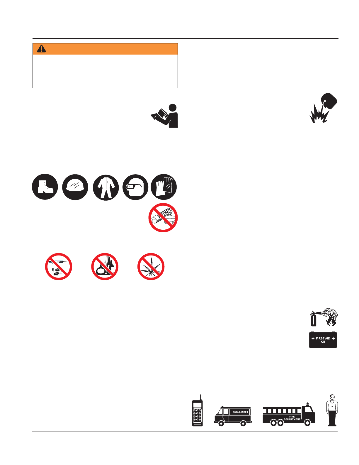
SAFETY
FOR YOUR SAFETY AND SAFETY OF OTHERS!
Safety precautions should be followed at all
times when operating this equipment. Failure to read and understand the Safety Messages and Operating Instructions could result
in injury to yourself and others.
This manual has been developed to
provide complete instructions for the
safe and efficient operation of this
equipment.
Before using this equipment ensure that the operating individual has read and understood all instructions in this
manual.
SAFETY MESSAGE ALERT SYMBOLS
HAZARD SYMBOLS
Potential hazards associated with the operation of this
equipment will be referenced with Hazard Symbols which
appear throughout this manual, and will be referenced in
conjunction with Safety Message Alert Symbols.
WARNING — Respiratory Hazards
ALWAYS wear approved respiratory
protection when required.
CAUTION — Rotating Parts Hazards
NEVER operate equipment with covers or
guards removed. Keep fingers, hands, hair
and clothing away from all moving parts to
prevent injury.
The three Safety Messages shown below will inform you
about potential hazards that could injure you or others.
The Safety Messages specifically address the level of exposure to the operator, and are preceded by one of three
words: DANGER, WARNING, or CAUTION.
DANGER
You WILL be
INJURED
KILLED
or
SERIOUSLY
if you DO NOT follow these
directions.
WARNING
You CAN be KILLED or
SERIOUSLY INJURED
if you DO NOT follow these directions.
CAUTION
CAUTION — Accidental Starting Hazards
ALWAYS place the equipment ON/OFF
switch in the OFF position when the
equipment is not in use.
CAUTION — Eye and Hearing Hazards
ALWAYS wear approved eye and hearing
protection.
CAUTION — Equipment Damage Hazards
Other important messages are provided throughout this
manual to help prevent damage to your equipment,
other property, or the surrounding environment.
You CAN be
INJURED
these directions.
PAGE 4 — MB25A REBAR BENDER • OPERATION AND PARTS MANUAL — REV. #3 (11/18/08)
if you DO NOT follow
Page 5
WARNING — Read This Manual
Failure to follow instructions in this manual may lead to
serious injury or even
operated by trained and qualified personnel only! This
equipment is for industrial use only.
GENERAL SAFETY
DO NOT operate or service this equipment
before reading this entire manual.
This equipment should not be operated by
persons under 18 years of age.
NEVER operate this equipment without proper protective
clothing, shatterproof glasses, steel-toed boots and other
protective devices required by the job.
NEVER operate this equipment when not
feeling well due to fatigue, illness or when
under medication.
NEVER operate this equipment under the
influence of drugs or alcohol.
DEATH
! This equipment is to be
RULES AND REGULATIONS
DO NOT wear loose clothing or jewelry. Contain long
hair. Keep hair, clothing, and gloves away from moving
parts. Rotating parts can cause injury if contacted.
ALWAYS keep work area clean and free of foreign matter
and debris. Also keep work area well lit.
NEVER operate the equipment in an
explosive atmosphere or near combustible
materials. An explosion or fire could result
causing severe
death.
DO NOT overreach. Keep proper footing and balance at
all times.
NEVER leave the equipment unattended. When not is
use, before servicing, and when changing accessories,
always unplug the equipment from the power source.
USE this equipment for its intended purpose only.
KEEP equipment clean for better and safer performance.
Keep handles dry, clean, and free from oil and grease.
INSPECT the equipment after each use. Replace any
damaged or worn parts immediately. Do not use
equipment if defective.
If a malfunction occurs, immediately unplug the
equipment from the power source and correct the
problem. If problem cannot be corrected, contact the
nearest MQ service center.
bodily harm or even
NEVER use accessories or attachments that are not
recommended by Multiquip for this equipment. Damage
to the equipment and/or injury to user may result.
Manufacturer does not assume responsibility for any
accident due to equipment modifications. Unauthorized
equipment modification will void all warranties.
Whenever necessary, replace nameplate, operation and
safety decals when they become difficult to read.
ALWAYS check the equipment for loosened threads or
bolts before starting.
MAINTAIN equipment is a safe operating condition at
all times.
KEEP bystanders, children, and visitors away while
operating the equipment. Distractions can cause loss of
control.
MB25A REBAR BENDER • OPERATION AND PARTS MANUAL — REV. #3 (11/18/08) — PAGE 5
ALWAYS store the equipment in a clean, dry location
out of the reach of children.
EMERGENCIES
ALWAYS know the location of the nearest
fire extinguisher
ALWAYS know the location of the nearest
first aid kit
In emergencies,
of the nearest phone or
Also know the phone numbers of the nearest
ambulance, doctor
information will be invaluable in case of emergency.
.
.
always
and
know the location
keep a phone on the job site
fire department
. This
.
Page 6

RULES AND REGULATIONS
ELECTRICAL SAFETY
■
ALWAYS test the
POWER
switch on the equipment before
operating. The purpose of this switch is to shut down the
power.
■
NEVER use a extension cord that is frayed or damaged
where the insulation has been cut.
■
NEVER carry the equipment by its power cord or
disconnect it by yanking the cord from the power outlet.
■
ALWAYS make certain that the proper extension cord
has been selected for the job. See Extension Cord
Gauge Selection Table.
■
NEVER allow power cord to
■
NEVER
■
When connecting the unit to a power receptacle, make
stand in water
lay in wate
r.
while operating the equipment.
sure the receptacle circuit is connected to either a GFCI
receptacle or a receptacle protected by a 20 amp circuit
breaker.
■
When plugging the unit into a power receptacle, check
the nameplate for the correct operating voltage.
Operating the rebar bender at the wrong voltage will
damage the electrical components. ALWAYS read the
nameplate before applying power.
■
This unit is equipped with a 3-prong male power plug.
DO NOT use a 2-prong adapter when plugging into a
wall outlet. This will defeat the purpose of the ground
circuit. If the plug does not fit into the receptacle, contact
a qualified electrician to install a 3-conductor wall
receptacle (outlet).
■
Avoid body contact with grounded surfaces such as
pipes, radiators, ranges and refrigerators. There is an
increased risk of electrical shock if your body is
grounded.
■
DO NOT expose the hydraulic power unit to rain or wet
conditions. Water entering the power unit will increase
the risk of electrical shock.
■
When operating the unit outdoors, be sure to use the
appropriate outdoor extension cord. This type of
extension cord reduces the risk of electrical shock.
■
ALWAYS remove the AC power cord from the power
source before performing any service or maintenance
on the unit. This preventative safety measure reduces
the possibility of accidental starting.
When operating near an arc welder, it is important the
both the unit and the welding equipment be connected
to the same earth ground. If they are not, server damage
to the unit, particularly to the power cord could occur.
Personal injury may also occur.
noitceleSeguaGdroCnoisnetxE
stloV teeFnidroCfohtgneL
erepmA
gnitaR
egnaR
V511 .tF52 .tF05 .tF001 .tF051 .tF002 .tF052 .tF003 .tF004 .tF005
V032 .tF05 .tF001 .tF002 .tF003 .tF004 .tF005 .tF006 .tF008 .tF0001
2-0 81 81 81 61 61 41 41 21 21
3-2 81 81 61 41 41 21 21 01 01
4-3 81 81 61 41 21 21 01 01 8
5-4 81 81 41 21 21 01 01 8 8
6-5 81 61 41 21 01 01 8 8 6
8-6 81 61 21 01 01 8 6 6 6
01-8 81 41 21 01 8 8 6 6 4
21-01 61 41 01 8 8 6 6 4 4
41-21 61 21 01 8 6 6 6 4 2
61-41 61 21 01 8 6 6 4 4 2
81-61 41 21 8 8 6 4 4 2 2
02-81 41 21 8 6 6 4 4 2 2
PAGE 6 — MB25A REBAR BENDER • OPERATION AND PARTS MANUAL — REV. #3 (11/18/08)
Page 7

ledoMA52BM
yticapaC8.oN-2.oN,)"1(52Ø-)"4/1(6Ø
sdneBfoegnaR°081-°0
SPECIFICATIONS
SNOITACIFICEPS.1ELBAT
rotoMA31,zH06,V511,es
dradnatS
tnempiuqE
TABLE 2. SIZE OF ROLLERS AND COLLARS
ahPelgniS
5-relloR2-hcnerWnellA
6-ralloC1-hcnerWdnE-nepO
1-revoCfoorpretaW1-revirdwercS
1-xoBlooT1-hctiwStooF
MB25A REBAR BENDER • OPERATION AND PARTS MANUAL — REV. #3 (11/18/08) — PAGE 7
Page 8

GENERAL INFORMATION
The
MQ MB25A Rebar Bender
as a portable on-site rebar bender, capable of bending inplace rebar to approved American Concrete Institute (ACI)
radius. Labor time and injuries are greatly reduced from
manually bending rebar. The MB25A is capable of bends
up to 180°.
The MB25A comes with 5 rollers and collars which can be
used in different combinations to match the diameter of
the rebar to be bent.
The MB25A comes with a foot switch which can start the
bending procedure with a push of the pedal instead of
pressing the start button.
An emergency button is available to immediately stop the
machine when something goes wrong during bending. The
roller then returns to the starting position.
is designed to be used
GENERAL INFORMATION
PAGE 8 — MB25A REBAR BENDER • OPERATION AND PARTS MANUAL — REV. #3 (11/18/08)
Page 9

COMPONENTS
Figure 1. MB25A Components
Figure 1 shows the components of the MB25A Rebar
Bender. These components are described below.
1. Table - Holds the roller, collar, stopper and the rebar
to be bended.
2. Roller - Works in combination with the collar depending
on the diameter of the rebar to bend.
3. Collar -Works in combination with the roller depending
on the diameter of the rebar to bend.
4. Stopper - Holds the rebar in place when bending.
5. Panel A - Holds the different controls for the rebar
bender.
6. Power Switch - Turns the power of the rebar bender
on or off.
MB25A REBAR BENDER • OPERATION AND PARTS MANUAL — REV. #3 (11/18/08) — PAGE 9
7. Start Switch - Starts the bending process.
8. Emergency Stop Switch - Stops the rebar bending
9. Angle Adjusting Knob - Used to "fine tune" the angle
10. Angle Select Dial - Sets the angle that the rebar is
11. Connector (for foot switch) - Connects to the foot
12. Handle - Used to lift the rebar bender.
and moves the roller back to the starting position.
after trial bends of a few pieces of rebar.
going to be bent.
switch to start the machine with a push of the pedal.
Page 10
OPERATION
SELECTION AND INSTALLATION OF ROLLER AND
COLLAR
WARNING
Keep fingers from the bending area. Moving parts can
cause serious injury.
Do not drop anything into the machine from the bending
area as this may damage the machine.
1. Select the roller and corresponding collar to match the
diameter of the rebar to be bent. See Table 2 for the
different combinations.
2. Apply multi-purpose grease to the roller.
3. Install the collar and the roller as shown in Figure 2.
8. Rotate the Angle Select Dial to the desired angle that
REBAR
CORRECT
WRONG
STOPPER
Figure 3. Stopper Position
the rebar is to be bent (Figure 4). If the selected angle
cannot be obtained by the Angle Select Dial, "fine tune"
the angle by using the Angle Adjusting Knob (Figure 5).
135º
180º
90º
45º
Figure 2. Roller and Collar Installation
4. When using a roller with a bearing, bearing must face
downward.
5. When using a collar with a bearing, bearing must face
downward.
6. To prevent the roller and the collar from coming off,
attach the washer securely with the bolt.
7. Position the stopper so that rebar to be bent is parallel
to the front of the stopper and tighten the rebar securely
in place. If the rebar is not parallel to the front, the
bending angle will be incorrect. See Figure 3.
ANGLE SELECT DIAL
Figure 4. Selecting the Bending Angle
ANGLE ADJUSTING KNOB
(+)
Figure 5. Fine Tuning the Bending Angle
(-)
9. Plug the power cord into a proper single-phase power
source. Make sure that the rebar bender is properly
grounded.
10. Turn the power switch on.
11. Hold the rebar firmly and press the Start Switch. This
will engage the clutch and the roller to bend the rebar.
12. After the rebar is bent to the desired angle, the roller
will automatically spring back to the starting position.
PAGE 10 — MB25A REBAR BENDER • OPERATION AND PARTS MANUAL — REV. #3 (11/18/08)
Page 11

OPERATION
USING THE ANGLE ADJUSTING KNOB
Depending on the diameter of the rebar and its tensile
strength, it may be necessary to "fine tune" the angle using the Angle Adjusting Knob after trial bends of a few
pieces of rebar.
1. The Angle Adjusting Knob is automatically locked when
EMERGENCY STOP SWITCH
1. To stop the rebar bender immediately in case anything
goes wrong in the bending process, press the
Emergency Stop Button (Figure 7). The roller on the
rebar bender will immediately stop and return to the
start position.
released. Unlock the knob by pulling it hard and sliding
the knob to the right or left to adjust the angle.
2. When the desired angle is selected, release the knob.
The knob will now be automatically locked.
USING THE FOOT SWITCH
Instead of the Start Switch, the Foot Switch can be used
to start the bending process. See Figure 6.
PLUG TO CONNECTOR
ON FRONT PANEL
PUSH PEDAL
TO START BENDING
WARNING
The roller goes back to start position very quickly after
bending because of the spring mechanism. Keep away
from the machine until the roller is completely back in
the start position to prevent any injury.
Front Panel
EMERGENCY STOP SWITCH
Figure 7. Emergency Stop Switch
Figure 6. Starting with the Foot Switch
1. Insert the plug of the foot switch to the Foot Switch
Connector on the front panel of the rebar bender.
2. Press the pedal on the foot switch to start bending.
3. When the bending angle is achieved, the roller will
automatically spring back to the start position.
It is not necessary to press the pedal continuously while bending. Once the pedal is
pressed bending will start and pedal can
be released.
DANGER
During operation of this rebar bender,
there exists the possibility of
electrocution, electrical shock or burn,
which can cause
even
DEATH!
severe bodily harm
or
To avoid these hazards:
NEVER use damaged or worn cables when plugging
the rebar bender into an AC power
receptacle.
WET
HANDS
NEVER grab or touch a live power
cord with wet hands.
NEVER stand in water and touch a
live power cord.
POWER
CORD
(POWER ON)
MB25A REBAR BENDER • OPERATION AND PARTS MANUAL — REV. #3 (11/18/08) — PAGE 11
Page 12

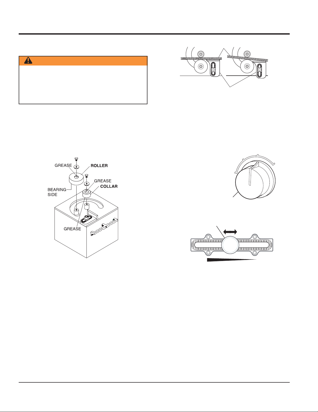
MAINTENANCE
REMOVING STEEL DEBRIS
2. Remove the rear panel and the bottom plate of the
machine so that the outer frame of the motor is visible
1. To remove steel debris from the machine, tilt it and
(Figure 9).
clear all debris from the outlet.
3. Remove the carbon brush cap of the motor outer frame
WARNING
Do not let debris or rust accumulate inside the machine
as this could lead to malfunction of the machine.
using a standard screwdriver.
4. Replace the carbon brushes with new ones.
5. Put back the cap and reinstall the rear and end panels
of the machine.
REPLACING CARBON BRUSHES
WARNING
Unplug unit from power source before replacing carbon
brushes.
When the carbon becomes less than 5 or 6 mm (1/4 inch)
the motor force deteriorates because of low rectification
(Figure 8). The carbon brushes need to be replaced.
5-6 mm
(1/4 inch)
Figure 8. Carbon Brush Size
1. Make sure that the power plug is not connected to the
power source.
CARBON BRUSH CAP
Figure 9. Replacing Carbon Brushes
PAGE 12 — MB25A REBAR BENDER • OPERATION AND PARTS MANUAL — REV. #3 (11/18/08)
Page 13

WARNING
Unplug unit from power source before troubleshooting.
MOTPMYSMELBORPELBISSOPNOITULOS
MAINTENANCE
GNITOOHSELBUORT.4ELBAT
dnetonlliwrableetS
ctulcsI.hctulcecalpeR
hctulcfoesuaceb
.gnippils
erA
?tcatnoc
odhctulcdnarotoM
ehtelihwkrowton
.nositnerruc
gnidnebniytiralugerrI
.selgna
?ssendrah
?demrofed
morfesionlamronbA
.rotom
?tuonrowh
?pordegatlovlamronbanaerehtsI .pordegatlovlamronbafoesuackcehC
?drahootsrableetserA
hctiwstengamnostisopedtsud
?tuonrowtcatnochctiwstengamsI.hctiwstengamecalpeR
?detcennocsideriwdaelsI.
?evitcefedrokaewrotomcirtcelesI.rotomriaperroecalpeR
tisopylreporpmireppotsehtsI
?hguonedenethgitton
iralugerrinaerehtsI
ocerutamraerA
rodenoi
rableetsehtniyt
ronekorbsenavgnilo
.sgniraeb
?tuonrowsgniraeberutamraerA.sgniraebwenh
tiwecalpeR
.hctiwstengamhsiloP
eriwdaeltcennoC
.ssendrahtcerrochtiwsrableetsesU
.reppotsfossenthgitdnagninoitisoptcerroC
.ssendrahtcerrochtiwsrableetsesU
stidnaerutamraevitcefedaecalpeR
?ecnalabfotuoerutamrasI .erutamrawenahtiwecalpeR
urbnobracerA.senowenhtiwecalpeR
sirotomtuptuorewoP
.tneiciffuston
MB25A REBAR BENDER • OPERATION AND PARTS MANUAL — REV. #3 (11/18/08) — PAGE 13
?tuonrowsehs
?nekorbsliocfonoitalusnisI.rotomroerutamraecalpeR
?egatlovnipordaerehtsI .
pordegatlovehtfoesuacehtkcehC
Page 14

EXPLANATION OF CODE IN REMARKS COLUMN
The following section explains the different symbols and
remarks used in the Parts section of this manual. Use the help
numbers found on the back page of the manual if there are any
questions.
The contents and part numbers listed in the parts section are
subject to change
guarantee the availibility of the parts listed.
Sample Parts List:
NO. PART NO. PART NAME QTY. REMARKS
1 12345 BOLT ...................... 1 ...... INCLUDES ITEMS W/
2
*
2*12347 WASHER, 3/8 IN. ... 1 ......
3 12348 HOSE ................... A/R ....MAKE LOCALLY
4 12349 BEARING ............... 1 ...... S/N 2345B AND ABOVE
NO. Column
Unique Symbols - All items with same unique symbol
, #, +, %, or >) in the number column belong to the same
(
*
assembly or kit, which is indicated by a note in the “Remarks”
column.
Duplicate Item Numbers - Duplicate numbers indicate
multiple part numbers are in effect for the same general
item, such as different size saw blade guards in use or a
part that has been updated on newer versions of the same
machine.
When ordering a part that has more than one
item number listed, check the remarks column for
help in determining the proper part to order.
without notice
WASHER, 1/4 IN. .............
. Multiquip does not
NOT SOLD SEPARATELY
MQ-45T ONLY
*
QTY. Column
Numbers Used - Item quantity can be indicated by a
number, a blank entry, or A/R.
A/R (As Required) is generally used for hoses or other parts
that are sold in bulk and cut to length.
A blank entry generally indicates that the item is not sold
separately. Other entries will be clarified in the “Remarks”
Column.
REMARKS Column
Some of the most common notes found in the “Remarks”
Column are listed below. Other additional notes needed to
describe the item can also be shown.
Assembly/Kit
unique symbol will be included when this item is purchased.
Indicated by:
“INCLUDES ITEMS W/(unique symbol)”
Serial Number Break
number range where a particular part is used.
Indicated by:
“S/N XXXXX AND BELOW”
“S/N XXXX AND ABOVE”
“S/N XXXX TO S/N XXX”
Specific Model Number Use
used only with the specific model number or model number
variant listed. It can also be used to show a part is NOT
used on a specific model or model number variant.
Indicated by:
“XXXXX ONLY”
“NOT USED ON XXXX”
- All items on the parts list with the same
- Used to list an effective serial
- Indicates that the part is
PART NO. Column
Numbers Used - Part numbers can be indicated by a
number, a blank entry, or TBD.
TBD (To Be Determined) is generally used to show a part
that has not been assigned a formal part number at time of
publication.
A blank entry generally indicates that the item is not sold
separately or is not sold by Multiquip. Other entries will be
clarified in the “Remarks” Column.
PAGE 14 — MB25A REBAR BENDER • OPERATION AND PARTS MANUAL — REV. #3 (11/18/08)
“Make/Obtain Locally”
purchased at any hardware shop or made out of available
items. Examples include battery cables, shims, and certain
washers and nuts.
“Not Sold Separately”
purchased as a separate item and is either part of an
assembly/kit that can be purchased, or is not available for
sale through Multiquip.
- Indicates that the part can be
- Indicates that an item cannot be
Page 15

MB25A REBAR BENDER
1 to 3 Units
Qty. P/N Description
2 ....... 6402520 ........ HOLDER CAP
2 ....... 6402510 ........ CARBON BRUSH
SUGGESTED SPARE PARTS
MB25A REBAR BENDER • OPERATION AND PARTS MANUAL — REV. #3 (11/18/08) — PAGE 15
Page 16

NAMEPLATE AND DECALS
MB25A — NAMEPLATE AND DECALS
1
1.Read owner’s manual
beforeoperating.
2.Keep unauthorized and
untrainedpeople away
frommachine during operation.
3.Keep fingers away from bending
areaduring operating.
4.Before bending, rebar must rest fully
withinbending area (between roller
andcollar).
8010780
SAFETY INSTRUCTIONS
5.If rebar is too brittle or defective, it
maybe broken during bending.
standnear the working
DO NOT
rollerside of the rebar bender.
6. considerthe safety of others
ALWAYS
whenbending.
7. disconnectAC plug from
ALWAYS
powersource when changing
accessories,such as rollers and
collarsor machine inspection.
PinchPoint
Movingparts can crush
andcut.
Keephands clear while
machineis operating.
DO NOT
8. wearlooseclothing or
jewelry.They can be caught in
movingparts.
9. operatemachine under the
NEVER
influenceof alcohol or drugs.
NEVER
10. operatethis equipment when
notfeeling well due to fatigue, illness
ortaking medicine.
11.Use only thatdoes not
graded rebar
exceedthe bending capacity of the
machine.
EyeHazard
Alwayswear safety goggles
anda full face shield when
bending.
ELECTRICAL
SHOCK
HAZARD
DANGER
Duringoperation of this equipment, there
electrocution
existsthe possibility of ,
electrical shock or burn
,which can cause
severe bodily harm DEATH!
oreven
Toavoidthese hazards:
NEVER use a worn or damaged power
cord.Replace defective cords immediately.
NEVER grab or touch a live power cord
withwet hands.
NEVER let power cords lay in water.
NEVER stand in water and touch a live
powercord.
ALWAYSconnect power cord to a grounded
outlet.
NEVER operate this equipment in damp or
wetconditions.
LiftingHazard
DO NOT lift or move
withoutassistance.
Liftwith one person at
eachend of the machine
usinglift handles.
MODEL
SERIAL NO.
2
3
6
RIGHT
B
WRONG
B
4
* Position the stopper (A) so that the rebar (B) to be bent is parallel to the
front of stopper
A
A
5
PAGE 16 — MB25A REBAR BENDER • OPERATION AND PARTS MANUAL — REV. #3 (11/18/08)
Page 17

MB25A — NAMEPLATE AND DECALS
NAMEPLATE AND DECALS
NO. PART NO. PART NAME QTY. REMARKS
1 8010780 SAFETY WARNING DECAL 1
2 NAMEPLATE ........................................................ 1 ......... CONTACT MQ PARTS DEPT.
3 8010750 ROLLER AND COLLAR DECAL 1
4 8005070 STOPPER INSTALLATION DECAL 2
5 8010770 ROLLER AND COLLAR INSTALLATION DECAL 1
6 8010760 ROLLER, COLLAR, AND TOOLS DECAL 1
MB25A REBAR BENDER • OPERATION AND PARTS MANUAL — REV. #3 (11/18/08) — PAGE 17
Page 18

BENDER ASSEMBLY
1
2
3
5
6
7
8
9
21
22
23
24
36
37
38
MB25A — BENDER ASSEMBLY
17
18
19
20
26
27
30
10
11
34
35
C
29
5
15
14
6
28
12
31
32
33
13
86
85
88
84
87
72
43
86
82
80
50
49
46
80
81
51
1
41
40
90
C
71
53
52
47
48
47
45
44
55
1
91
82
83
54
90
70
42
44
79
78
77
76
75
89
88
73
74
73
67
66
65
61
60
59
NOTES:
1
INCLUDED WITH ITEM 46.
69
68
64
A
63
62
59
60
58
57
56
1
2
5
4
16
25
39
PAGE 18 — MB25A REBAR BENDER • OPERATION AND PARTS MANUAL — REV. #3 (11/18/08)
Page 19

MB25A — BENDER ASSEMBLY
BENDER ASSEMBLY
NO. PART NO. PART NAME QTY. REMARKS
1 M5SB122000 HEX HEAD BOLT 12 X 20 2
2 M5T4273800 WASHER A 2
3 9008090 ROLLER 625 1
3 9008080 ROLLER 622 1
3 9008070 ROLLER 619 1
3 9008060 ROLLER 616 1
3 9008050 ROLLER 613 1
3 9008040 ROLLER 610 ........................................................ 1 ......... OPTIONAL
4 9008130 COLLAR 625 1
4 9008120 COLLAR 622 1
4 9008110 COLLAR 619 1
4 3510370 COLLAR 616 1
4 3510360 COLLAR 613 1
4 3510350 COLLAR 610 1
5 7550050 ALLEN HEAD SCREW 10X25 12
6 7514000 ALLEN HEAD SCREW 8X15 4
7 9009580 TABLE 1
8 H5HB103000 ALLEN HEAD SCREW 10X30 1
9 4500380 SHOCK ABSORBER 1
10 M5B2050000 ALLEN HEAD BOLT 20X50 1
11 M5T4267800 SQUARE NUT 1
12 3502090 STOPPER PLATE 1
13 H5HB082000 HEX HEAD SCREW 8X20 4
14 3251620 STOPPER 1
15 M5K1008500 STOPPER KEY 1
16 3510260 OUTPUT SHAFT 1
17 7410130 STOP RING RTW 100 1
18 7103180 BEARING 6309DDU 1
19 7411320 SNAP RING IRTW 55 1
20 C5BTAFI385 NEEDLE BEARING HMK4530 1
21 3510270 ROLLER SHAFT 1
22 3510250 ARM 1
23 7651300 WASHER, FLAT M 14 1
24 7516200 ALLEN HEAD SCREW 14X40 1
25 7200090 NEEDLE BEARING HMK3230 1
26 7103190 BEARING 6218DDU 1
27 6601090 PIN ø13 X13 2
28 M5B6205Z00 BEARING 6205Z 1
29 3252160 FRAME 1
30 3600180 GEAR WHEEL 1
MB25A REBAR BENDER • OPERATION AND PARTS MANUAL — REV. #3 (11/18/08) — PAGE 19
Page 20

BENDER ASSEMBLY
1
2
3
5
6
7
8
9
21
22
23
24
36
37
38
MB25A — BENDER ASSEMBLY
17
18
19
20
26
27
30
10
11
34
35
C
29
5
15
14
6
28
12
31
32
33
13
86
85
88
84
87
72
43
86
82
80
50
49
46
80
81
51
1
41
40
90
C
71
53
52
47
48
47
45
44
55
1
91
82
83
54
90
70
42
44
79
78
77
76
75
89
88
73
74
73
67
66
65
61
60
59
NOTES:
1
INCLUDED WITH ITEM 46.
69
68
64
A
63
62
59
60
58
57
56
1
2
5
4
16
25
39
PAGE 20 — MB25A REBAR BENDER • OPERATION AND PARTS MANUAL — REV. #3 (11/18/08)
Page 21

MB25A — BENDER ASSEMBLY
BENDER ASSEMBLY (continued)
NO. PART NO. PART NAME QTY. REMARKS
31 3508830 SPRING GUIDE 1
32 C5SW0601M0 WASHER, LOCK 6 1
33 7513070 ALLEN HEAD SCREW 6X35 1
34 H5HW100100 WASHER HW 10 10
35 7515050 ALLEN HEAD SCREW 10X35 10
36 3251290 TORSION COIL COLLAR 1
37 H6HW060100 WASHER, FLAT HW 6 10
38 7513030 SCREW 6X18 10
39 7200070 NEEDLE BEARING HK2526 1
40 7539010 SCREW W/ LOCK WASHER XR 4X16 2
41 6100060 RECTIFIER 1
42 H6HB051500 SCREW HB 5X15 4
43 3252220 GEAR CASE COVER 1
44 7101040 BEARING 6002Z 2
45 3510230 GEAR COLLAR No.6 1
46 6100040 MAGNET CLUTCH 1
47 7301130 THRUST NEEDLE ROLLER BEARING AS 1104 2
48 7301120 THRUST NEEDLE ROLLER BEARING AXK 1104 1
49 7550120 SCREW 5X12 3
50 H6HW050100 WASHER, FLAT 5 3
51 3601690 GEAR No. 5 1
52 7101220 BEARING 6004ZZ 1
53 7411040 SNAP RING RTW 42 1
54 3701250 KEY 1
55 3601700 GEAR No.6 1
56 7512100 BOLT HB 5X40 4
57 C5SW0501M0 WASHER, LOCK 5 4
58 7600100 WASHER, FLAT 5 4
59# 6402520 HOLDER CAP 2
60# 6402510 CARBON BRUSH 2
61# 6402450 MOTOR CASE 1
62# 6402420 STATOR 115V 1
63# 6402380 FAN GUIDE 1
64# 6402390 SCREW 5 X80 2
65# 7105020 BEARING 1
66# 6402370 INSULATOR WASHER 1
67 # 6402340 ARMATURE 115V 1
68 # 6402320 INSULATOR WASHER FOR BEARING 1
69 7000060 BEARING 6202VV 1
70 M5HB102500 ALLEN HEAD SCREW 10X25 4
MB25A REBAR BENDER • OPERATION AND PARTS MANUAL — REV. #3 (11/18/08) — PAGE 21
Page 22

BENDER ASSEMBLY
1
2
3
5
6
7
8
9
21
22
23
24
36
37
38
MB25A — BENDER ASSEMBLY
17
18
19
20
26
27
30
10
11
34
35
C
29
5
15
14
6
28
12
31
32
33
13
86
85
88
84
87
72
43
86
82
80
50
49
46
80
81
51
1
41
40
90
C
71
53
52
47
48
47
45
44
55
1
91
82
83
54
90
70
42
44
79
78
77
76
75
89
88
73
74
73
67
66
65
61
60
59
NOTES:
1
INCLUDED WITH ITEM 46.
69
68
64
A
63
62
59
60
58
57
56
1
2
5
4
16
25
39
PAGE 22 — MB25A REBAR BENDER • OPERATION AND PARTS MANUAL — REV. #3 (11/18/08)
Page 23

MB25A — BENDER ASSEMBLY
BENDER ASSEMBLY (continued)
NO. PART NO. PART NAME QTY. REMARKS
71 3252180 GEAR CASE 1
72 7515100 ALLEN HEAD SCREW 10 X50 3
73 7101010 BEARING 6000Z 2
74 3601660 GEAR No.2 1
75 3601680 GEAR No.4 1
76 C5T4230800 KEY D 1
77 7101340 BEARING 6003VV 1
78 7410100 SNAP RING STW 17 1
79 3601670 GEAR No.3 1
80 7101080 BEARING 6004Z 2
81 3601720 GEAR No.8 1
82 3701600 KEY FOR GEAR No.8 2
83 3601710 GEAR No.7 1
84 M5B6006Z00 BEARING 6006Z 1
85 3601730 GEAR No.9 1
86 3701200 KEY FOR SHAFT WITH GEAR 2
87 3600530 SHAFT GEAR 1
88 7515110 ALLEN HEAD SCREW 10X60 4
89 3252170 GEAR BASE 1
90 3508860 GEAR BASE PIN 4
91 7102030 BEARING 6202Z 1
A 6014110 MOTOR 115V ...................................................... 1 ......... INCLUDES ITEMS W/ #
MB25A REBAR BENDER • OPERATION AND PARTS MANUAL — REV. #3 (11/18/08) — PAGE 23
Page 24

4
153
HOUSING ASSEMBLY
MB25A — HOUSING ASSEMBLY
38
102
108
1
2
102
42
111
42
112
114
NOTES:
1
INCLUDED WITH ITEM 109
2
INCLUDED WITH ITEM 110
3
INCLUDED WITH ITEM 115
4
INCLUDED WITH ITEM 117
92
107
38
93
101
94
32
95
94
32
95
96
110
98
A
121
98
99
116
A
120
97
109
113
102
117
118
3
119
32
103
32
103
B
100
98
99
129
130
131
137
103
32
122
123
32
126
133
100
98
134
99
106
115
37
128
135
136
138
127
127
B
139
38
143
6
32
142
125
132
103
102
102
140
38
145
144
123
141
103
32
94
32
38
104
105
124
38
139
139
94
32
93
38
92
147
146
38
139
32
103
143
6
PAGE 24 — MB25A REBAR BENDER • OPERATION AND PARTS MANUAL — REV. #3 (11/18/08)
Page 25

MB25A — HOUSING ASSEMBLY
HOUSING ASSEMBLY
NO. PART NO. PART NAME QTY. REMARKS
6 7514000 ALLEN HEAD SCREW 8X15 4
32 C5SW0601M0 WASHER, LOCK 6 24
37 H6HW060100 WASHER, FLAT 6 4
38 7513030 ALLEN HEAD SCREW 6X18 12
42 H6HB051500 ALLEN HEAD SCREW 5X15 4
92 7513120 ALLEN HEAD SCREW 6 X60 2
93 3250440 HANDLE 2
94 7513010 ALLEN HEAD SCREW 6X2 8
95 7538190 BOLT W/SPRING WASHER XR 4 X 20 3
96 3000140 FRAME HOUSING 1
97 6200160 MAGNET SWITCH 1
98 7600010 WASHER, FLAT 4 4
99 7700030 HEX NUT 4 3
100 6101350 NYLON CLAMP 2
101 3301460 PANEL B 1
102 7538090 SCREW W/ LOCK WASHER XR 5 X 10 10
103 7700050 HEX NUT 6 16
104 3300610 OUTSIDE BRACKET, TORSION COIL 1
105 H6HB062000 ALLEN HEAD SCREW 6 X 20 2
106 4007570 TORSION COIL SPRING 1
107 3301480 PANEL A 1
108 6200770 POWER SWITCH 1
109 6200230 START SWITCH 1
110 6200240 EMERGENCY STOP SWITCH 1
111 7511030 SET SCREW 4 X 20 1
112 3503590 ANGLE ADJUSTING KNOB 1
113 3250600 ANGLE ADJUSTING PLATE 1
114 6101060 ANGLE SELECT DIAL 1
115 6200170 ROTARY SWITCH 1
116 7600050 WASHER, FLAT 10 1
117 6101280 FOOT SWITCH CONNECTOR F 1
118 7538000 SCREW W/ LOCK WASHER XR 3 X8 1
119 6101290 FOOT SWITCH CONNECTOR CAP 1
120 M5NM030100 HEX NUT 3 1
121 7556020 HEX NUT 5X0.9 4
122 M5NM080100 HEX NUT 8 1
123 C5SW0801M0 WASHER, FLAT 8 5
124 3510220 INSIDE BRACKET, TORSION COIL 1
125 7551020 ALLEN HEAD SCREW 10X40 1
126 3251270 CARRIER 1
127 M5SNR25S00 SNAP RING STW 25 2
128 7513050 ALLEN HEAD SCREW 6X25 4
129 7538020 SCREW W/ LOCK WASHER XR 3X18 8
130 6200190 MICRO SWITCH 4
131 4600100 MICRO SWITCH HOLDER PLATE 1
MB25A REBAR BENDER • OPERATION AND PARTS MANUAL — REV. #3 (11/18/08) — PAGE 25
Page 26

4
153
HOUSING ASSEMBLY
MB25A — HOUSING ASSEMBLY
92
38
102
108
1
2
102
42
111
42
112
114
NOTES:
1
INCLUDED WITH ITEM 109
2
INCLUDED WITH ITEM 110
3
INCLUDED WITH ITEM 115
4
INCLUDED WITH ITEM 117
107
3
113
117
38
109
118
125
132
103
102
102
140
38
145
144
123
141
103
32
94
32
94
32
104
105
124
38
139
139
38
93
38
92
147
146
38
139
32
103
143
6
93
101
94
32
95
94
32
95
96
110
98
A
121
98
99
116
A
120
97
102
119
32
103
32
103
B
100
98
99
129
130
131
137
103
32
122
123
32
126
133
100
98
134
99
106
115
37
128
135
136
138
127
127
B
139
38
143
6
32
142
PAGE 26 — MB25A REBAR BENDER • OPERATION AND PARTS MANUAL — REV. #3 (11/18/08)
Page 27

MB25A — HOUSING ASSEMBLY
HOUSING ASSEMBLY (continued)
NO. PART NO. PART NAME QTY. REMARKS
132 7410080 SNAP RING ETW 8 1
133 4007030 COIL SPRING 1
134 7532010 SCREW 4X8 1
135 3251280 MICRO SWITCH BASE 1
136 3501960 ANGLE ADJUSTING STICK 1
137 6601060 PIN ø10 X10 1
138 3510290 FIXED COLLAR 1
139 3510200 OUTPUT SHAFT GUIDE BRACKET 4
140 3510280 OUTPUT SHAFT GUIDE 1
141 7514140 ALLEN HEAD SCREW 8X18 4
142 3301470 BOTTOM PLATE 1
143 3503420 COLLAR FOR END PLATE 4
144 6301010 CORD WITH PLUG 1
145 6600030 CLAMP, CABLE 1
146 7538030 SCREW W/ LOCK WASHER XR 4X6 2
147 C5Y8411000 STRAIN RELIEF, CABLE 1
153 9002120 FOOT SWITCH ASSEMBLY 1
MB25A REBAR BENDER • OPERATION AND PARTS MANUAL — REV. #3 (11/18/08) — PAGE 27
Page 28

MB25A — TOOL BOX AND TOOLS ASSEMBLY
TOOL BOX AND TOOLS ASSEMBLY
ROLLERS
COLLARS
3
4
5
6
7
1
12
9
8
10
11
13
14
15
16
17
2
PAGE 28 — MB25A REBAR BENDER • OPERATION AND PARTS MANUAL — REV. #3 (11/18/08)
Page 29

MB25A — TOOL BOX AND TOOLS ASSEMBLY
TOOL BOX AND TOOLS ASSEMBLY
NO. PART NO. PART NAME QTY. REMARKS
1 9020120 TOOL BOX ASSY ................................................. 1 ......... INCLUDES ITEMS W/
2
3
4
5
6
7
8
9
10
11
12
13
14
15
16
17
*
*
*
*
*
*
*
*
8103050 TOOL BOX 1
9008090 ROLLER 625 (WITH BEARING) 1
9008080 ROLLER 622 (WITH BEARING) 1
9008070 ROLLER 619 (WITH BEARING) 1
9008060 ROLLER 616 (WITH BEARING) 1
9008050 ROLLER 613 (WITH BEARING) 1
9008130 COLLAR 625 (WITH BUSHING) 1
9008120 COLLAR 622 (WITH BUSHING) 1
9008110 COLLAR 619 (WITH BUSHING) 1
*
3510370 COLLAR 616 1
*
3510360 COLLAR 613 1
*
3510350 COLLAR 610 1
*
8201020 OPEN END WRENCH 17 X19 MM 1
*
8201510 SCREWDRIVER 1
*
8200020 ALLEN WRENCH M2 1
*
8200120 ALLEN WRENCH M17 1
*
*
MB25A REBAR BENDER • OPERATION AND PARTS MANUAL — REV. #3 (11/18/08) — PAGE 29
Page 30

MB25A — WIRING DIAGRAM
Power Supply
S
R
Black
White
Brown
Red
6
White
4
5
Rectifier
1
2
White
Power Switch
Model : JW-L11RRK
Light Blue
1
1b
Black
3
Black
Black
Light
Blue
Start
Emergency Stop
Orange
Orange
Orange
A1/a
Black
R/1
S/3
Orange
Red
T/5
Magnet Switch
Model : S-U12FT
V/4
Light
Blue
W/6
Brown
U/2
Black
A2/b
Foot Switch Connector
Orange
Gray
12
Dark
Blue
Light Blue
Black
3
4
0
Dark Blue
Black
White
Red
2
1
Gray
45º
90º
135º
180º
Micro Switch
White
Red
Rotary Switch
Orange
Red
Red
Red
Red
Black
M
Motor
Black
BlackBlack
MC
Magnet Clutch
PAGE 30 — MB25A REBAR BENDER • OPERATION AND PARTS MANUAL — REV. #3 (11/18/08)
Page 31

TERMS AND CONDITIONS OF SALE — PARTS
PAYMENT TERMS
Terms of payment for parts are net 30 days.
FREIGHT POLICY
All parts orders will be shipped collect or
prepaid with the charges added to the invoice.
All shipments are F.O.B. point of origin.
Multiquip’s responsibility ceases when a signed
manifest has been obtained from the carrier,
and any claim for shortage or damage must be
settled between the consignee and the carrier.
MINIMUM ORDER
The minimum charge for orders from Multiquip
is $15.00 net. Customers will be asked for
instructions regarding handling of orders not
meeting this requirement.
RETURNED GOODS POLICY
Return shipments will be accepted and credit
will be allowed, subject to the following provisions:
1. A Returned Material Authorization must
be approved by Multiquip prior to shipment.
2. To obtain a Retur n Material Authorization,
a list must be provided to Multiquip Parts
Sales that defines item numbers, quantities, and descriptions of the items to be
returned.
a. The parts numbers and descriptions
must match the current parts price
list.
b. The list must be typed or computer
generated.
c. The list must state the reason(s) for
the return.
d. The list must reference the sales
order(s) or invoice(s) under which the
items were originally purchased.
e. The list must include the name and
phone number of the person requesting the RMA.
3. A copy of the Return Material Authorization must accompany the return shipment.
4. Freight is at the sender’s expense. All
parts must be returned freight prepaid to
Multiquip’s designated receiving point.
5. Parts must be in new and resalable con-
6. The following items are not returnable:
7. The sender will be notified of any material
8. Such material will be held for five working
9. Credit on returned parts will be issued at
10. In cases where an item is accepted, for
11. Credit issued will be applied to future
PRICING AND REBATES
Prices are subject to change without prior
notice. Price changes are effective on a specific date and all orders received on or after that
date will be billed at the revised price. Rebates
for price declines and added charges for price
increases will not be made for stock on hand
at the time of any price change.
Multiquip reserves the right to quote and sell
dition, in the original Multiquip package (if
any), and with Multiquip part numbers
clearly marked.
a. Obsolete parts. (If an item is in the
price book and shows as being replaced by another item, it is obsolete.)
b. Any parts with a limited shelf life
(such as gaskets, seals, “O” rings,
and other rubber parts) that were purchased more than six months prior to
the return date.
c. Any line item with an extended dealer
net price of less than $5.00.
d. Special order items.
e. Electrical components.
f. Paint, chemicals, and lubricants.
g. Decals and paper products.
h. Items purchased in kits.
received that is not acceptable.
days from notification, pending instructions. If a reply is not received within five
days, the material will be returned to the
sender at his expense.
dealer net price at time of the original
purchase, less a 15% restocking charge.
which the original purchase document
can not be determined, the price will be
based on the list price that was effective
twelve months prior to the RMA date.
purchases only.
direct to Government agencies, and to Original
Equipment Manufacturer accounts who use
our products as integral parts of their own
products.
SPECIAL EXPEDITING SERVICE
A $35.00 surcharge will be added to the invoice
for special handling including bus shipments,
insured parcel post or in cases where Multiquip
must personally deliver the parts to the carrier.
LIMITATIONS OF SELLER’S LIABILITY
Multiquip shall not be liable hereunder for
damages in excess of the purchase price of the
item with respect to which damages are
claimed, and in no event shall Multiquip be
liable for loss of profit or good will or for any
other special, consequential or incidental dam-
ages.
LIMITATION OF WARRANTIES
No warranties, express or implied, are made
in connection with the sale of parts or trade
accessories nor as to any engine not manufac-
tured by Multiquip. Such warranties made in
connection with the sale of new, complete units
are made exclusively by a statement of war-
ranty packaged with such units, and Multiquip
neither assumes nor authorizes any person to
assume for it any other obligation or liability
whatever in connection with the sale of its
products. Apart from such written statement of
warranty, there are no warranties, express,
implied or statutory, which extend beyond the
description of the products on the face hereof.
Effective: February 22, 2006
MB25A REBAR BENDER • OPERATION AND PARTS MANUAL — REV. #3 (11/18/08) — PAGE 31
Page 32

OPERATION AND PARTS MANUAL
HERE’S HOW TO GET HELP
PLEASE HAVE THE MODEL AND SERIAL
NUMBER
UNITED STATES
Multiquip Corporate Office MQ Parts Department
18910 Wilmington Ave. Tel. (800) 421-1244 800-427-1244 Fax: 800-672-7877
Carson, CA 90746 Fax (800) 537-3927 310-537-3700 Fax: 310-637-3284
Contact: mq@multiquip.com
Mayco Parts Warranty Department
800-306-2926 Fax: 800-672-7877 800-421-1244, Ext. 279 Fax: 310-537-1173
310-537-3700 Fax: 310-637-3284 310-537-3700, Ext. 279
Service Department Technical Assistance
800-421-1244 Fax: 310-537-4259 800-478-1244 Fax: 310-631-5032
310-537-3700
MEXICO UNITED KINGDOM
MQ Cipsa Multiquip (UK) Limited Head Office
Carr. Fed. Mexico-Puebla KM 126.5 Tel: (52) 222-225-9900 Hanover Mill, Fitzroy Street, Tel: 0161 339 2223
Momoxpan, Cholula, Puebla 72760 Mexico Fax: (52) 222-285-0420 Ashton-under-Lyne, Fax: 0161 339 3226
Contact: pmastretta@cipsa.com.mx Lancashire OL7 0TL
CANADA
Multiquip
4110 Industriel Boul. Tel: (450) 625-2244
Laval, Quebec, Canada H7L 6V3 Fax: (450) 625-8664
Contact: jmartin@multiquip.com
ON-HAND
WHEN CALLING
Contact: sales@multiquip.co.uk
© COPYRIGHT 2008, MULTIQUIP INC.
Multiquip Inc. and the MQ logo are registered trademarks of Multiquip Inc. and may not be used, reproduced, or altered without written permission. All other trademarks are the
property of their respective owners and used with permission.
This manual MUST accompany the equipment at all times. This manual is considered a permanent part of the equipment and should remain with the unit if resold.
The information and specifications included in this publication were in effect at the time of approval for printing. Illustrations, descriptions, references and technical data contained in
this manual are for guidance only and may not be considered as binding. Multiquip Inc. reserves the right to discontinue or change specifications, design or the information
published in this publication at any time without notice and without incurring any obligations.
Your Local Dealer is:
 Loading...