

Page 1

OPERATION MANUAL
SERIES
MODEL C30HDGA
CONCRETE PUMP
(ZENITH 416 GAMMA GASOLINE ENGINE)
Revision #1 (09/09/19)
To find the latest revision of this publication or
associated parts manual, visit our website at:
www.multiquip.com
THIS MANUAL MUST ACCOMPANY THE EQUIPMENT AT ALL TIMES.
Page 2

PROPOSITION 65 WARNING
PAGE 2 — MAYCO C30HDGA CONCRETE PUMP • OPERATION MANUAL — REV. #1 (09/09/19)
Page 3
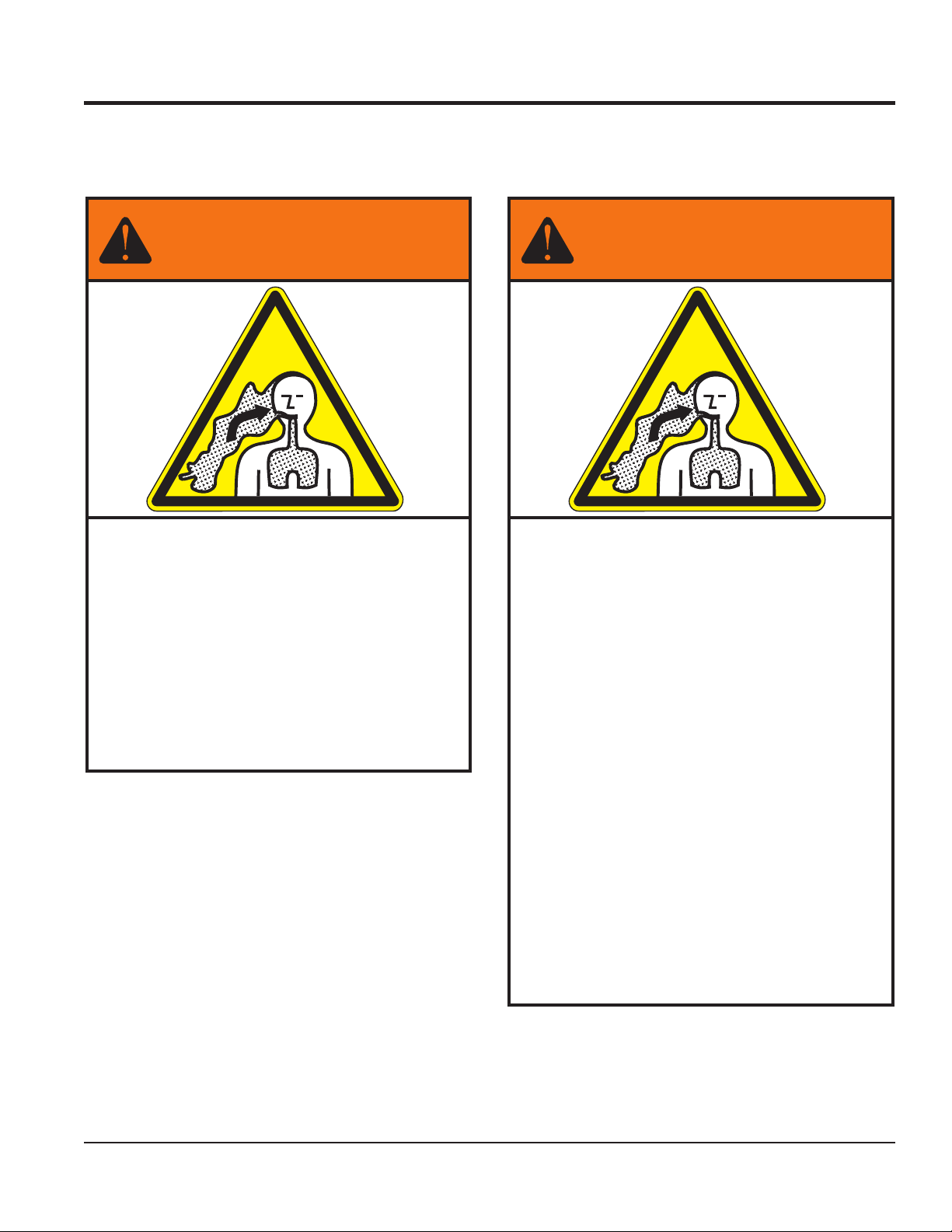
Grinding/cutting/drilling of masonry, concrete, metal and
other materials with silica in their composition may give
off dust or mists containing crystalline silica. Silica is a
basic component of sand, quartz, brick clay, granite and
numerous other minerals and rocks. Repeated and/or
substantial inhalation of airborne crystalline silica can
cause serious or fatal respiratory diseases, including
silicosis.In addition, California and some other
authorities have listed respirable crystalline silica as a
substance known to cause cancer. When cutting such
materials, always follow the respiratory precautions
mentioned above.
WARNING
Grinding/cutting/drilling of masonry, concrete, metal and
other materials can generate dust, mists and fumes
containing chemicals known to cause serious or fatal
injury or illness, such as respiratory disease, cancer,
birth defects or other reproductive harm. If you are
unfamiliar with the risks associated with the particular
process and/or material being cut or the composition of
the tool being used, review the material safety data
sheet and/or consult your employer, the material
manufacturer/supplier, governmental agencies such as
OSHA and NIOSH and other sources on hazardous
materials. California and some other authorities, for
instance, have published lists of substances known to
cause cancer, reproductive toxicity,or other harmful
effects.
Control dust, mist and fumes at the source where
possible. In this regard use good work practices and
follow the recommendations of the manufacturers or
suppliers, OSHA/NIOSH, and occupational and trade
associations.Water should be used for dust
suppression when wet cutting is feasible. When the
hazards from inhalation of dust, mists and fumes cannot
be eliminated, the operator and any bystanders should
always wear a respirator approved by NIOSH/MSHA for
the materials being used.
WARNING
SILICOSIS WARNING RESPIRATORY HAZARDS
SILICOSIS/RESPIRATORY WARNINGS
MAYCO C30HDGA CONCRETE PUMP • OPERATION MANUAL — REV. #1 (09/09/19) — PAGE 3
Page 4

C30HDGA Concrete Pump
Proposition 65 Warning ........................................... 2
Silicosis/Respiratory Warnings ................................ 3
Safety Information ............................................. 5–10
Specifications ........................................................ 11
Dimensions ............................................................ 12
Important Hand Signals ......................................... 13
General Information ......................................... 14–16
Components (Pump) ....................................... 18–19
Components (Control Box) .................................... 20
Components (Engine) ............................................ 21
Inspection ........................................................ 22–24
Startup/Shutdown .................................................. 25
Operation ......................................................... 26–30
Maintenance .................................................... 31–39
Trailer Maintenance ......................................... 40–41
Trailer Guidelines ............................................. 42–55
Troubleshooting ............................................... 56–57
Engine Fault Codes ......................................... 58–63
Appendix — Concrete Mix Information ............ 64–66
Wiring Diagram (Wiring Harness) .......................... 67
Electrical Component Locator ......................... 68–69
TABLE OF CONTENTS
NOTICE
Specifications are subject to change without notice.
PAGE 4 — MAYCO C30HDGA CONCRETE PUMP • OPERATION MANUAL — REV. #1 (09/09/19)
Page 5
SAFETY INFORMATION
Do not operate or service the equipment before reading
the entire manual. Safety precautions should be followed
at all times when operating this equipment.
Failure to read and understand the safety
messages and operating instructions could
result in injury to yourself and others.
SAFETY MESSAGES
The four safety messages shown below will inform you
about potential hazards that could injure you or others. The
safety messages specifi cally address the level of exposure
to the operator and are preceded by one of four words:
DANGER, WARNING, CAUTION
SAFETY SYMBOLS
Potential hazards associated with the operation of this
equipment will be referenced with hazard symbols which
may appear throughout this manual in conjunction with
safety messages.
DANGER
Indicates a hazardous situation which, if not avoided,
WILL result in DEATH or SERIOUS INJURY.
WARNING
Indicates a hazardous situation which, if not avoided,
COULD result in DEATH or SERIOUS INJURY.
CAUTION
Indicates a hazardous situation which, if not avoided,
COULD result in MINOR or MODERATE INJURY.
or NOTICE.
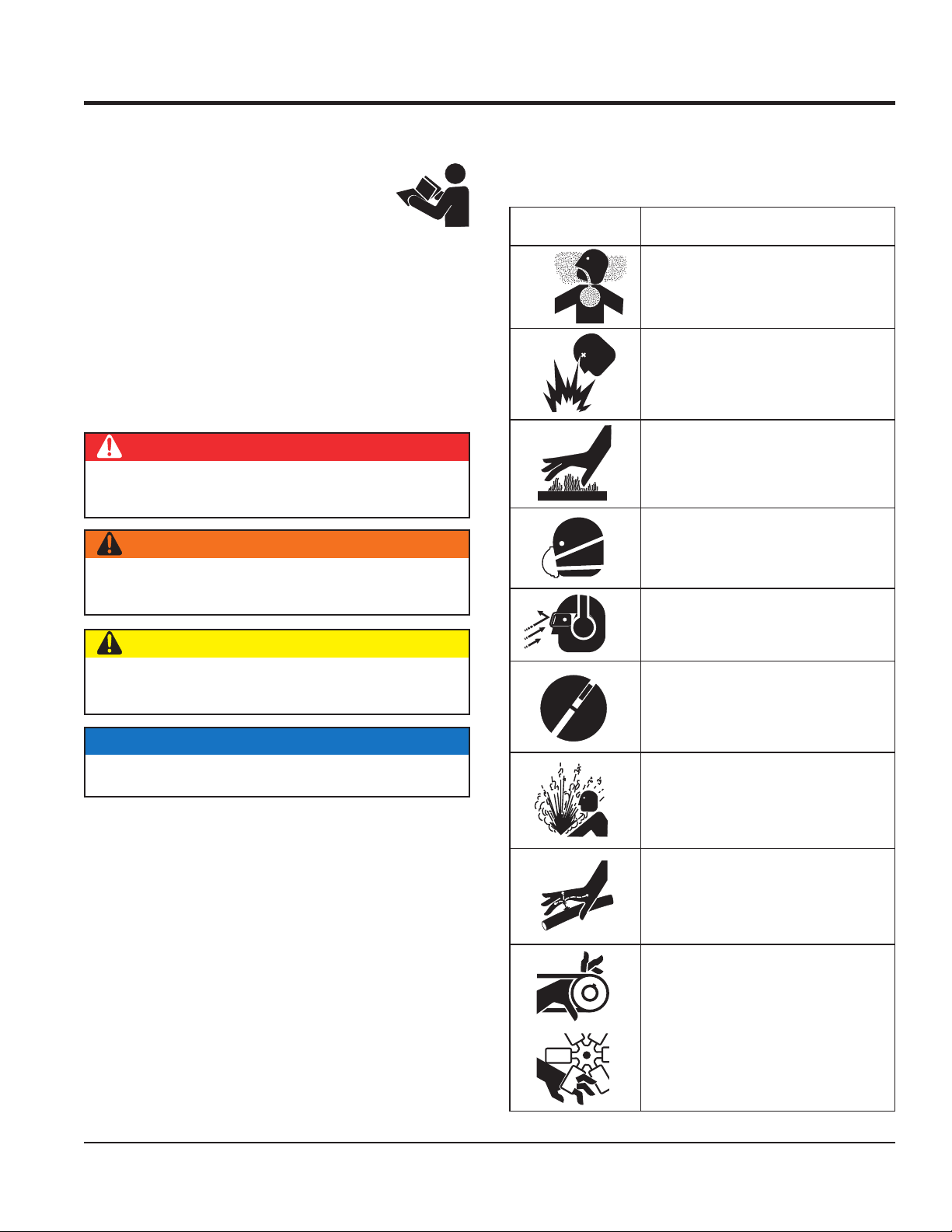
Symbol Safety Hazard
Lethal Exhaust Gas Hazards
Explosive Fuel Hazards
Burn Hazards
Respiratory Hazards
Eye and Hearing Hazards
OFF
Accidental Starting Hazards
NOTICE
Addresses practices not related to personal injury.
MAYCO C30HDGA CONCRETE PUMP • OPERATION MANUAL — REV. #1 (09/09/19) — PAGE 5
Pressure Hazards
Hydraulic Fluid Hazards
Rotating Parts Hazards
Page 6

SAFETY INFORMATION
GENERAL SAFETY
PUMP SAFETY
pump volatile, explosive, fl ammable or low fl ash
The engine fuel exhaust gases contain poisonous carbon
monoxide. This gas is colorless and odorless, and can
The engine of this equipment requires an adequate free
operate this equipment in any
pump corrosive chemicals or water containing
toxic substances. These fl uids could create serious
health and environmental hazards. Contact local
emergency or safety devices.
These devices are intended for operator safety.
severe injury,
. Disconnection of any of
CAUTION
NEVER operate this equipment without proper protective
clothing, shatterproof glasses, respiratory protection,
hearing protection, steel-toed boots and other protective
devices required by the job or city and state regulations.
NEVER operate this equipment when not
feeling well due to fatigue, illness or when
on medication.
NEVER operate this equipment under the infl uence of
drugs or alcohol.
NOTICE
This equipment should only be operated by trained and
qualifi ed personnel 18 years of age and older.
DANGER
NEVER
point fl uids. These fl uids could ignite or explode.
cause death if inhaled.
fl ow of cooling air. NEVER
enclosed or narrow area
where free fl ow of the air is
restricted. If the air fl ow is
restricted it will cause injury
to people and property and
serious damage to the
equipment or engine.
NEVER operate the equipment in an explosive
atmosphere or near combustible materials. An
explosion or fi re could result causing severe
bodily harm or even death.
WARNING
DANGEROUS
GAS FUMES
Whenever necessary, replace nameplate, operation and
safety decals when they become diffi cult read.
Manufacturer does not assume responsibility for any
accident due to equipment modifi cations. Unauthorized
equipment modifi cation will void all warranties.
NEVER use accessories or attachments that are not
recommended by Multiquip for this equipment. Damage
to the equipment and/or injury to user may result.
ALWAYS know the location of the nearest
fi re extinguisher.
ALWAYS know the location of the nearest
fi rst aid kit.
ALWAYS know the location of the nearest phone or keep
a phone on the job site. Also, know the phone numbers
of the nearest ambulance, doctor and fi re department.
This information will be invaluable in the case of an
emergency.
NEVER
authorities for assistance.
NEVER disconnect any
Disconnection of these devices can cause
bodily harm or even death
these devices will void all warranties.
PAGE 6 — MAYCO C30HDGA CONCRETE PUMP • OPERATION MANUAL — REV. #1 (09/09/19)
Page 7

CAUTION
NEVER lubricate components or attempt service on a
Refer to the Engine Owner’s Manual for engine technical
questions or information recommended by Multiquip for
this equipment. Damage to the equipment and or injury
remove the ignition key when leaving the pump
block the wheels on the unit when using on
use properly rated hoses and clamps —
allow the pump a proper amount of time to
Fix damage to machine and replace any broken parts
store equipment properly when it is not being
used. Equipment should be stored in a clean, dry location
out of the reach of children and unauthorized personnel.
place hands or fingers inside engine
operate the engine with heat shields or
running machine.
NEVER block or restrict flow from discharge hose.
Remove kinks from discharge line before starting pump.
Operation with a blocked discharge line can cause clutch
to fail.
DO NOT operate this equipment unless the hopper grate,
guards and safety devices are attached and in place.
CAUTION must be exercised while servicing this
equipment. Rotating and moving parts can cause injury
if contacted.
Keep hands out of the hopper when the engine is
running.
NOTICE
In winter drain water from the lubrication box to prevent
freezing.
ALWAYS be sure the operator is familiar with proper
safety precautions and operation techniques before
using pump.
Keep all inexperienced and unauthorized people away
from the equipment at all times.
Before start-up, check the hopper and remove all foreign
matter and debris.
DO NOT use worn or damaged hose couplings, inspect
all hoses and couplings for wear. Replace any worn or
defective hoses or couplings immediately.
Unauthorized equipment modifications will void all
warranties.
Check all fasteners periodically for tightness. Also check
towing tongue bolt, lock nut and wheel lug nuts for wear.
Test the pump’s emergency stop switch. The purpose
of this test is to shut down the engine in the event of an
emergency.
SAFETY INFORMATION
to user may result.
ALWAYS
unattended.
ALWAYS
a slope.
ALWAYS
1,500 PSI or higher.
ALWAYS
cool before servicing.
ALWAYS keep the machine in proper running condition.
ALWAYS ensure pump is on level ground before use.
immediately.
ALWAYS
ENGINE SAFETY
WARNING
DO NOT
compartment when engine is running.
NEVER
guards removed.
DO NOT remove the engine oil drain plug
while the engine is hot. Hot oil will gush
out of the oil tank and severely scald any
persons in the general area of the pump.
CAUTION
NEVER touch the hot exhaust manifold,
muffl er or cylinder. Allow these parts to cool
before servicing equipment.
Multiquip strongly encourages the operator to take the
safety training courses offered by the American Concrete
Pumping Association (www.concretepumpers.com).
MAYCO C30HDGA CONCRETE PUMP • OPERATION MANUAL — REV. #1 (09/09/19) — PAGE 7
Page 8
SAFETY INFORMATION
NOTICE
FUEL SAFETY
BATTERY SAFETY
drop the battery. There is a possibility that the
keep the battery charged. If the battery is not
charge battery if frozen. Battery can explode.
When frozen, warm the battery to at least 61°F (16°C).
recharge the battery in a well-ventilated
environment to avoid the risk of a dangerous concentration
If the battery liquid (dilute sulfuric acid) comes into
, rinse eyes immediately with plenty
of water and contact the nearest doctor or hospital to
NEGATIVE battery terminal
keep battery cables in good working condition.
NEVER run engine without an air fi lter or with a dirty air
fi lter. Severe engine damage may occur. Service air fi lter
frequently to prevent engine malfunction.
NEVER tamper with the factory settings
of the engine or engine governor. Damage
to the engine or equipment can result
if operating in speed ranges above the
maximum allowable.
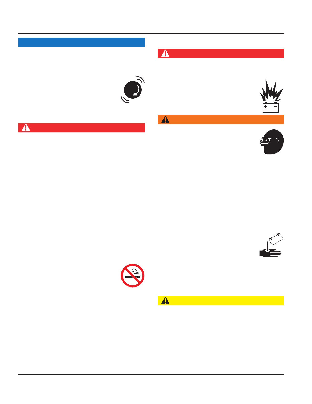
DANGER
DO NOT start the engine near spilled fuel or combustible
fl uids. Fuel is extremely fl ammable and its vapors can
cause an explosion if ignited.
ALWAYS refuel in a well-ventilated area, away from
sparks and open fl ames.
ALWAYS use extreme caution when working with
fl ammable liquids.
DO NOT fi ll the fuel tank while the engine is running
or hot.
DANGER
DO NOT
battery will explode.
DO NOT expose the battery to open fl ames,
sparks, cigarettes, etc. The battery contains
combustible gases and liquids. If these
gases and liquids come into contact with a
fl ame or spark, an explosion could occur.
WARNING
ALWAYS wear safety glasses when
handling the battery to avoid eye irritation.
The battery contains acids that can cause
injury to the eyes and skin.
Use well-insulated gloves when picking up
the battery.
ALWAYS
charged, combustible gas will build up.
DO NOT
DO NOT overfi ll tank, since spilled fuel could ignite if it
comes into contact with hot engine parts or sparks from
the ignition system.
Store fuel in appropriate containers, in well-ventilated
areas and away from sparks and fl ames.
NEVER use fuel as a cleaning agent.
DO NOT smoke around or near the
equipment. Fire or explosion could result
from fuel vapors or if fuel is spilled on a
hot engine.
To prevent leakage, tighten the fuel cap until it clicks.
Slowly open fuel cap to release pressure.
ALWAYS
of combustible gases.
If the battery liquid (dilute sulfuric acid)
comes into contact with clothing or skin,
rinse skin or clothing immediately with
plenty of water.
contact with eyes
seek medical attention.
CAUTION
ALWAYS disconnect the
before performing service on the equipment.
ALWAYS
Repair or replace all worn cables.
PAGE 8 — MAYCO C30HDGA CONCRETE PUMP • OPERATION MANUAL — REV. #1 (09/09/19)
Page 9
TRANSPORTING SAFETY
CAUTION
TOWING SAFETY
Check the tire air pressure on both towing vehicle and
Trailer tires should be infl ated to 80 psi cold.
safety
attach trailer’s safety chains to towing
make sure the vehicle and trailer directional,
backup, brake and trailer lights are connected and
• Secure portable power cables in cable tray with tie
unless
posted otherwise. Recommended off-road towing is not
Avoid sudden stops and starts. This can cause skidding
or jack-knifi ng. Smooth, gradual starts and stops will
Trailer should be adjusted to a level position at all times
Raise and lock trailer wheel stand in up position when
underneath wheels to prevent
underneath the trailer’s bumper
Use the trailer’s swivel jack to adjust the trailer height to
NEVER allow any person or animal to stand underneath
the equipment while lifting.
NOTICE
Before lifting, make sure that the equipment parts are not
damaged and screws are not loose or missing.
ALWAYS make sure forklift forks are inserted into pockets
(if applicable) as far as possible when lifting the pump.
ALWAYS shut down engine before transporting.
NEVER lift the equipment while the engine is running.
Tighten fuel tank cap securely to prevent fuel from
spilling.
Use one-point suspension hook and lift straight upwards.
DO NOT lift machine to unnecessary heights.
ALWAYS tie down equipment during transport by
securing the equipment with straps, rope or chains.
CAUTION
Check with your local county or state safety
towing regulations, in addition to meeting
Department of Transportation (DOT)
Safety Towing Regulations, before towing
your pump.
In order to reduce the possibility of an accident while
transporting the pump on public roads, ALWAYS make
sure the trailer that supports the pump and the towing
vehicle are mechanically sound and in good operating
condition.
ALWAYS shut down engine before towing.
Make sure the hitch and coupling of the towing vehicle
are rated equal to or greater than the trailer gross vehicle
weight rating.
SAFETY INFORMATION
trailer.
Also check the tire tread wear on both vehicles.
ALWAYS make sure the trailer is equipped with a
chain.
ALWAYS properly
vehicle.
ALWAYS
working properly.
DOT requirements include the following:
• Connect and test electric brake operation.
wraps.
The maximum speed for highway towing is 55 MPH
to exceed 15 MPH or less depending on type of terrain.
improve towing.
Avoid sharp turns to prevent rolling.
when towing.
towing.
Place chock blocks
rolling while parked.
Place support blocks
to prevent tipping while parked.
a level position while parked.
ALWAYS inspect the hitch and coupling for wear. NEVER
tow a trailer with defective hitches, couplings, chains, etc.
MAYCO C30HDGA CONCRETE PUMP • OPERATION MANUAL — REV. #1 (09/09/19) — PAGE 9
Page 10

SAFETY INFORMATION
ENVIRONMENTAL SAFETY/DECOMMISSIONING
Decommissioning is a controlled process used to safely
retire a piece of equipment that is no longer serviceable.
If the equipment poses an unacceptable and unrepairable
safety risk due to wear or damage, or is no longer cost
effective to maintain (beyond life-cycle reliability) and is to
be decommissioned (demolition and dismantlement), be
sure to follow the rules below.
EMISSIONS INFORMATION
The diesel engine used in this equipment has been
designed to reduce harmful levels of carbon monoxide
(CO), hydrocarbons (HC) and nitrogen oxides (NOx)
This engine has been certifi ed to meet US EPA evaporative
Attempting to modify or make adjustments to the engine
emission system by unauthorized personnel without proper
training could damage the equipment or create an unsafe
Additionally, modifying the fuel system may adversely affect
evaporative emissions, resulting in fi nes or other penalties.
The emission control label is an integral part of the emission
If a replacement emission label is needed, please contact
NOTICE
DO NOT pour waste or oil directly onto the ground, down
a drain or into any water source.
Contact your country’s Department of Public
Works or recycling agency in your area and
arrange for proper disposal of any electrical
components, waste or oil associated with
this equipment.
When the life cycle of this equipment is over, remove
battery and bring to appropriate facility for lead
reclamation. Use safety precautions when handling
batteries that contain sulfuric acid.
When the life cycle of this equipment is over, it is
recommended that the frame and all other metal parts
be sent to a recycling center.
Metal recycling involves the collection of metal from
discarded products and its transformation into raw
materials to use in manufacturing a new product.
Recyclers and manufacturers alike promote the process
of recycling metal. Using a metal recycling center
promotes energy cost savings.
NOTICE
contained in diesel exhaust emissions.
emissions requirements in the installed confi guration.
condition.
Emission Control Label
system and is strictly controlled by regulations.
The label must remain with the engine for its entire life.
your authorized engine distributor.
PAGE 10 — MAYCO C30HDGA CONCRETE PUMP • OPERATION MANUAL — REV. #1 (09/09/19)
Page 11
SPECIFICATIONS
Table 1. C30HDGA Pump Specifications
Pump Type Reciprocating Piston
Pumping Rate Up to 25 cu. yds. per hour*
Vertical Pumping Height Up to 150 ft. (45.73 m)
Horizontal Pumping Distance 400 - 500 ft. (122 - 152 m)*
Max. Concrete Piston Face Pressure 500 PSI
Maximum Aggregate Size 1/2 in. minus (12.7 mm)
Hopper Capacity 6 cu. ft. etc.
Material Hose
Weight 2,950 lbs. (1,338 Kg)
Lube oil Box 7 Gallons (26.5 Liters)
Remote Control 125 ft. cable Standard
Tire Size
* Volume output will vary depending on mix design, slump, line size used and job site conditions.
2" or 2-1/2"
(50.8 or 63.5 mm)"
7.35" x 14"
(187 x 356 mm)
Table 2. Engine Specifications
Model ZENITH 416 GAMMA
Type
Bore × Stroke
Compression Ratio 11:1
Displacement 97.1 cu. (1,591 cc)
Continuous Output 45 H.P. @2700 R.P.M.
Fuel Tank Capacity Approx. 11 U.S. Gallons (42 liters)
Fuel Type Unleaded Gasoline
Lube Oil Capacity 3.49 qts. (3.3 liters)
Engine Speed
Full Load
Engine Speed
Full Idle
Air Cleaner Air Horn Type
Engine Lubrication
Starting Method Electric Start
Spark Plug B4ES
Spark Plug Gap
Dimension (L x W x H) 20.10 x 22.50 x 25.80 in. (509.9 x 527.5 x 654.5 mm)
Dry Net Weight 178 lbs (126.3 Kg.)
4 stroke, overhead valve, single cylinder
horizontal shaft gasoline engine
3.032 in. × 3.362 in.
(77 mm × 85.4 mm)
2650 rpm ±100 (No Load 2750 rpm +/- 50)
(Load 2750 rpm +/- 100)
950 rpm ±100
SAE 10W-30 (Oil Grade)
SG or SF (Service Class)
0.8 - 0.9 in
(0.031-0.035 mm).
MAYCO C30HDGA CONCRETE PUMP • OPERATION MANUAL — REV. #1 (09/09/19) — PAGE 11
Page 12

DIMENSIONS
F
A
B
Table 3. Pump Dimensions
Reference
Letter
A 76 (1930)
B 14.5 (368)
C 16 (406)
Dimensions
in. (mm)
MAYC0
C-30HDGA
C
D
145 IN. (3.68 M) DISCHARGE
CONE IN TRAVEL
POSITION
D 161 (4089)
E 63.5 (1612)
F 59.5 (1511)
PAGE 12 — MAYCO C30HDGA CONCRETE PUMP • OPERATION MANUAL — REV. #1 (09/09/19)
E
Page 13

IMPORTANT HAND SIGNALS
DRIVE IN BACK UP
CHUTE UP CHUTE DOWN
STOP PUMP LITTLE BIT
STOP START PUMP
SPEED UP
ADD WATER
4-GALLONS
SLOW PUMP
DOWN
ALL DONE
CLEAN-UP
PULL FORWARD
Figure 1. Operation Hand Signals
BACK IN
MAYCO C30HDGA CONCRETE PUMP • OPERATION MANUAL — REV. #1 (09/09/19) — PAGE 13
Page 14

GENERAL INFORMATION
The following operating principles and operating suggestions
should prove helpful in the successful operation of your
concrete pump. Your new “small line” concrete pump has
been designed to give you many years of service when
operated properly. A study of the following paragraphs is
important to the successful operation of your new Directflow Concrete Placer.
All concrete pumps require a high level of operator skill and
more frequent service than most of the other construction
equipment. The highly abrasive nature of concrete under
pressure makes it extremely important that expendable
wear components be inspected at regular intervals between
jobs to prevent having to replace these items during a pour.
Experience has proved that inconsistency of batched
concrete mixes and frequent moving of the line requires the
operator to be readily available at all times during pumping
to stop the pump and prevent abuse to the unit which may
occur if unexpected blockages develop.
PUMP MIX GUIDELINES
When ordering concrete, be certain to advise the concrete
supplier that you require a “pump mix”. The Direct-flow
manifold will pump a wide variety of materials, but certain
basic principles must be followed to assure successful
pumping, as follows:
Generally speaking, the washed concrete sand and
#4 aggregate (pea gravel) should conform to A.S.T.M.
standards in regard to sieve analysis. Sands in some areas
are washed clean of the #100 and #200 mesh fines, which
results in separation and jamming in the manifold while
pumping under pressure.
As a general rule, the use of approximately six sacks of
cement, 70% washed concrete sand and 30% #4 pea gravel
per yard of concrete will result in a pumpable mix. The
ideal nature of sand and rock in certain areas may permit
you to increase the percentage of rock or adjust the mix
considerably to meet the job requirements. When possible,
you may experiment with various mixes in your area to
determine the degree of versatility of the Direct-flow Pump.
Uniform gradation of the washed concrete sand and the
1/2” minus aggregate along with sufficient cement content
and water are important to a successful pump operation.
A recommended pumpable mix design would be 70% sand
and 30% aggregate-cement content to be a minimum of
6 sacks. (564 lbs.)
NOTICE
Your local sand and rock engineers will give you the
S.S.D. weights of sand and rock required in your local
area which will yield one cubic yard per the above
recommendation.
Sample Design Mix - 3000 Psi 3/8 in. Slump 4- 5 in.
Type II Cement 6.49 sack/cu. yd 611 lbs.
Sand Sat. Surf. Dry 2000 lbs.
#4 Gravel Sat. Surf. Dry 864 lbs.
#3 Gravel Sat. Surf. Dry 0 lbs.
Water 48 Gallons 400 lbs.
Total Weight 3,906 lbs
Admixture WRDA-79 26 oz.
Water 7.40 gal/sack
If this condition develops, check with your concrete
suppliers engineers and get their recommendations for
supplementing the lack of the fines. The use of locally
accepted ad-mixes may be required. (For example,
Pozzolith, Bentonite Clay, Plastiments, etc.) When properly
prescribed, additives form the plastic paste sometimes
necessary to hold the cement and aggregate together.
NOTICE
If jamming conditions in the pump or hose occur for
any reason at all, do not attempt to use more power to
correct the condition.
Determine the cause of jamming, correct it and resume
pumping. Trying to force material through under jammed
conditions may result in damage to the drive system, thus
voiding any warranty services
PAGE 14 — MAYCO C30HDGA CONCRETE PUMP • OPERATION MANUAL — REV. #1 (09/09/19)
Test laboratory data has proven in many areas that the
above mix guidelines have produced concrete rated at
3000 psi (28 day test) and upwards of 5000 psi with an
increase in cement.
In some areas where the gradation of sand and rock is ideal
and sufficient cement is used along with admixtures, the
Mayco small line concrete pump will handle up to a 50-50
ratio of sand and rock.
When the mix is designed for wet gunning applications, it
is normal to increase the cement (up to 7.5 or 8 sacks) and
change the sand to rock ratio to 85% sand and 15% rock.
The Mayco concrete pump will valve efficiently when using
cellular-foam concrete mixes upwards of 70 lbs. per cubic
foot wet density. Below 70 lbs. materials (roof decks), the
valving becomes inefficient.
Page 15
GENERAL INFORMATION
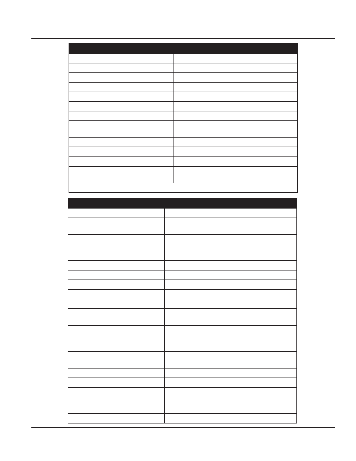
HOW IT WORKS
The C30HDGA concrete pump has one main pumping
piston which is valved by means of two ball checks. (A
inlet, and B outlet.)
The secondary piston is used as a compensator piston to
smooth out the pulsations of a single piston action. Note:
The compensator will not start operating until material is
pumped into the line and back pressure develops.
The compensator spring, which is installed on the
compensator piston rod, deflects with each piston stroke.
This “spring cushion”, in conjunction with the cam profile,
produces and uninterrupted smooth flow of material under
average pumping conditions.
The pumping cylinder (Figure 2) retracts drawing the
material past the ball (A) and filling the cylinder. The
compensator piston is pumping the material out to the
nozzle and causing ball (B) to seat preventing the material
from returning to the pumping cylinder intake.
An automatic, centrifugal clutch is installed to engage and
disengage the pumping action without stopping or starting
the engine. The centrifugal clutch is set at 1100 R.P.M. The
engine idle speed is approximately 900 R.P.M.; therefore,
the clutch is completely disengaged at idle. The throttle
settings while pumping should always maintain an engine
R.P.M. high enough to prevent the clutch from slipping and
burning the clutch lining.
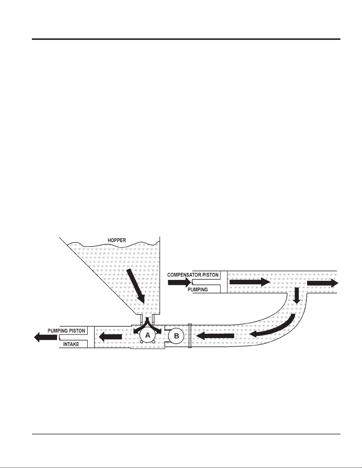
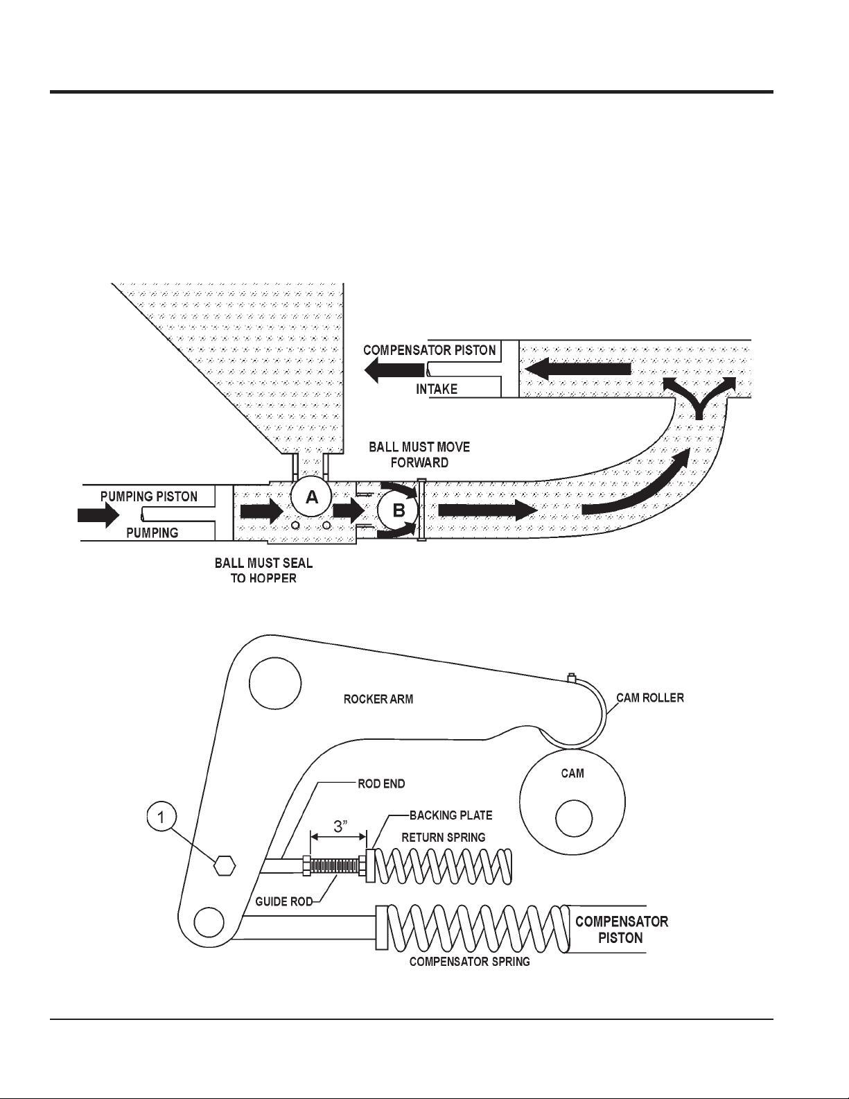
The return spring which is installed on the rocker arm, is
installed to eliminate shock and stress between the cam
roller and the cam weldment when the pump is in operation.
If the return spring is removed or replaced for any reason,
maintain the backing plate dimension of 3” as shown on
Figure 3, to produce the proper pre-loading of the spring
for a smooth performance.
Figure 2. Pumping Cylinder
MAYCO C30HDGA CONCRETE PUMP • OPERATION MANUAL — REV. #1 (09/09/19) — PAGE 15
Page 16
GENERAL INFORMATION
The pumping piston (Figure 3) is forcing the material past
ball (B) and out to the nozzle, also seating ball A so that the
material will not flow back to the hopper. This action also
fills the compensating piston for the next stroke.
Figure 4 shows the relationship between the return spring,
the compensator spring and the rocker arm to maintain a
smooth performance. DO NOT tighten the bolt (Item 1)
completely, the rod end must be able to move.
The return spring is installed to eliminate shock and stress
between the cam roller and the cam weldment when
the pump is in operation. If the return spring is removed
or replaced for any reason, maintain the backing plate
dimension (3-inches) as shown to produce proper preloading of the spring for a smooth performance.
Figure 3. Pumping Pistons
Figure 4. Return Spring, Compensator Spring and Rocker Arm Interaction
PAGE 16 — MAYCO C30HDGA CONCRETE PUMP • OPERATION MANUAL — REV. #1 (09/09/19)
Page 17
NOTES
MAYCO C30HDGA CONCRETE PUMP • OPERATION MANUAL — REV. #1 (09/09/19) — PAGE 17
Page 18
1
3
5
10
6
7 8
9
12
13
14
27
17
21
23
20
11
22
2
4
18
19
15
MAYC0
C-30HDGA
24
25
26
16
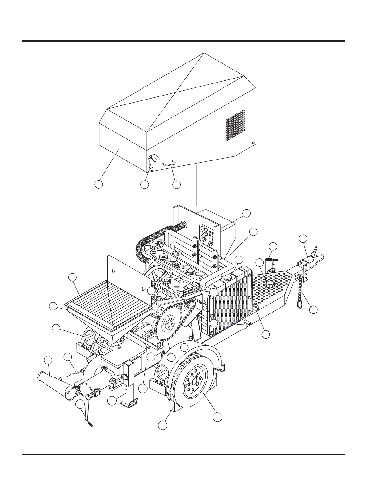
COMPONENTS (PUMP)
Figure 5. Pump Components
PAGE 18 — MAYCO C30HDGA CONCRETE PUMP • OPERATION MANUAL — REV. #1 (09/09/19)
Page 19

COMPONENTS (PUMP)
Figure 5 illustrates the location of the major components
for the C30HDGA Concrete Pump. The function of each
component is described below:
1. Discharge Cone — Connect 3" elbow to this discharge
port, then connect 3" x 2" reducer to elbow.
2. Discharge Cone Safety Latch — When towing of the
pump is required, ALWAYS secure the discharge cone
to latch located on the manifold.
3. Rear Running Lights — ALWAYS check and make
sure both the right and left running lights are functioning
correctly before towing the pump.
4. Hopper — Concrete from a Redi-Mix truck is poured into
this hopper. The hopper can hold 6.0 cu. ft of concrete.
NEVER put hands or any other parts of you body into
the hopper.
5. Safety Grill — The safety grill should be locked at all
times when the pump is being towed. Under normal
working conditions, raise and place the safety grill on
the support hooks which are located on splash guard.
6. Compartment Hood — NEVER operate the pump with
the hood removed. Installed on the pump frame is a safety
interlock device which will disable high speed if the hood
is removed or in the up position (open).
7. Hood Fastener — When the hood is in the down position,
secure the rubber latch to this fastener.
8. Hood Lift Handle — Grip this handle, pull upward then
back to raise the compartment hood.
9. Control Box — Contains the mechanical and electrical
components required to run the pump. Below is a list of
those components:
• Throttle Control Switch
• Pumping Control
• Check Engine Indicator
• Hood Open Indicator
• Engine Hour Meter
• Ignition Switch
• Remote Connector
10. Radiator/Cap — Fill with a water/anti-freeze type solution
as recommended in the maintenance section of this
manual. ALWAYS make sure that the radiator is filled to
the proper operating level before starting the engine.
11. Fuel Tank/Cap — Fill with unleaded fuel. Fuel tank (cell)
holds approximately 11 gallons (42 liters). DO NOT top
off fuel. Wipe up any spilled fuel immediately.
12. Tow End Jack Stand — Use this jack stand to level and
support the pump.
13. Tow Hitch Coupler — Requires a 2-inch ball hitch or a
3-inch pintle. Capable of towing 5,000 lbs.
14. Safety Chain — ALWAYS attach safety chain to the
towing vehicle. NEVER tow the pump with the safety
chain unattached.
15. Engine Safety Device — This device will return the
engine speed to idle if the compartment hood is in the
up position. The compartment hood must be in the down
position for the pump to operate at high rpm's.
16. Grease Port Console — This console allows for the
remote lubrication of components on the pump.
17. Access Door — There are four access doors on the
pump. Remove these door to gain access to drive and
piston assemblies when maintenance is required.
18. Drive Chain — Keep this chain properly lubricated and
aligned at all times. Lubricate this chain as specified in
the maintenance section of this maintenance.
19. Steel Latch — Secure this rubber latch to the hood
fastener whenever the pump is in use or being towed.
20. Tires Ply — The tire ply (layers) number is rated in letters;
This trailer uses 4-ply tires.
21. Chock Blocks — Place these blocks (not included as
part of your concrete pump package) under each trailer
wheel to prevent rolling.
22. Pump End Jack Stand — Use this jack stand to level
and support the pump.
23. Discharge Cone Release Lever — secures the
discharge cone to the "Y" manifold; also relieves manifold
pressure.
24. Documentation Box — Contains engine and pump
operation, parts and maintenance information.
25. Lubrication Box — This box is empty when shipped from
the factory. Please fill with 7 gallons ( 26.5 liters) of SAE
motor oil for first time use. Also check the dual clean-out
point on bottom of lubrication box for a secure tight fit.
26. Overflow Bottle — Fill with coolant. Maintain coolant at
proper level. See fluid level markings on side of bottle.
27. Cam Bearing — Felt ring must be periodically lubricated
applying 4 or 5 drops of 30 wt. motor oil until the felt
ring is moist.
MAYCO C30HDGA CONCRETE PUMP • OPERATION MANUAL — REV. #1 (09/09/19) — PAGE 19
Page 20

COMPONENTS (CONTROL BOX)
Figure 6. Pump Control Box Components
Figure 6 illustrates the location of the major components
for the C30HDGA Control Box. The function of each
component is described below:
1. Throttle Control Switch — This is a variable speed
type control. Holding the control switch to the left
increases the engine speed. To place the engine at
IDLE speed, hold the control switch to the right and
let the engine run for 3-5 minutes.
2. Emergency Stop Button — In the event of an
emergency or to shutdown the engine, push RED
emergency stop button inward. This will stop the
engine. To restart engine, emergency stop button must
be released from the stop position. Simply pull back on
the emergency stop button to release.
3. Ignition Switch — Insert the ignition key here to start
the engine. Turn the key clockwise to the ON position,
then continue turning clockwise to the START position
and release. To stop the engine turn the key fully
counter-clockwise to the STOP position.
4. Remote Control Input Connector — Insert the
remote control input cable into this connector.
5. Pumping Control Switch — This 3-position switch
controls the pumping of the pump. The left most
position is for use with the remote control unit, the
center position is for off (prevents pumping), and the
right most position is for normal pump operation.
6. Hourmeter — Display's the number of hours the pump
has been in use.
7. Hood Open Lamp — When lit (red) indicates that the
hood has been raised (open) during pumping operation.
This condition will force the engine into idle mode.
8. Check Engine Lamp — When lit (yellow) indicates that
an engine error as occurred. See Table 7 for a listing
of engine diagnostic error codes.
PAGE 20 — MAYCO C30HDGA CONCRETE PUMP • OPERATION MANUAL — REV. #1 (09/09/19)
Page 21
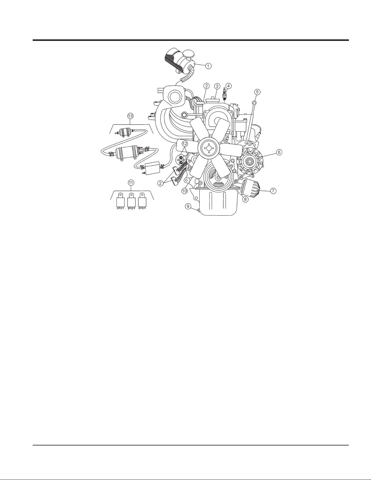
COMPONENTS (ENGINE)
Figure 7. Zenith 416 Gamma Engine Components
Figure 7 illustrates the location of the basic components
for the Zenith 416 Gamma gasoline engine. The function
of each component is described below:
1. Air Filter — Prevents dirt and other debris from
entering the fuel system. Remove wing-nut on top of air
filter cannister to gain access to filter element. Replace
only with manufacturer's recommended type air filter.
2. Fuse Connector — Contains fuses for electrical
system. Replace with only recommended type fuses.
3. Oil Filler Port Cap — Remove this cap to add engine
oil to the crankcase. Fill with recommended type oil
as specified.
4. Spark Plug — Provides spark to the ignition system.
Set spark plug gap to 0.6 - 0.7 mm (0.028 - 0.031 inch).
Clean spark plug once a week.
5. Dipstick — Remove this dipstick to determine if engine
oil is low. Maintain oil level at the "H" marking on the
dipstick. NEVER run engine with low oil.
7. Oil Filter — Replace this oil filter as recommended in
the maintenance section of this manual.
8. Fan V-Belt — ALWAYS make sure that V-belt is
properly tensioned. A loose or defective V-belt can
adversely affect the performance of the pump.
9. Crankcase Drain Plug — Remove this plug to
drain engine oil from the crankcase. Replace
with recommended engine oil as specified in the
maintenance section of this manual.
10. Cooling Fan Blades — Make sure that the blades of
the cooling fan are not bent or broken. A damaged fan
blade can cause the engine to run hot and overheat.
11. Control Relays — Includes a main relay, fuel pump
relay and starter relay. Replace only with recommended
type relays.
12. Starter Motor/Solenoid — NEVER allow concrete or
any foreign debris to come in contact with the starter
motor/solenoid.
6. Alternator — Provides power to the electrical system.
Replace only with manufacturer's recommended type
alternator.
MAYCO C30HDGA CONCRETE PUMP • OPERATION MANUAL — REV. #1 (09/09/19) — PAGE 21
13. Fuel Filter/Fuel Pump/Fuel Regulator — Replace
or clean the fuel filter, fuel pump or fuel regulator as
specified in the maintenance section of this manual.
Page 22

INSPECTION
WARNING
NEVER operate the pump in a confined
area or enclosed area structure that
does not provide ample free flow of air.
ALWAYS wear approved eye and
hearing protection when operating
the pump.
NEVER operate the engine with the
engine hood removed. The possibility
exists of hands, long hair, or clothing
becoming entangled with the V-belt,
causing injury and bodily harm.
NEVER place hands or feet inside
the hopper. ALWAYS shut down the
engine before performing any kind of
maintenance service on the pump.
FUEL CHECK
DANGER
Handle fuel safely. Motor fuels are highly flammable
and can be dangerous if mishandled. NEVER smoke
while refueling. NEVER attempt to refuel the pump
when the engine is hot or running.
DANGER
Gasoline is extremely flammable and
its vapors can cause an explosion
if ignited. NEVER start the engine
near spilled fuel or combustible fluids.
NEVER fill the fuel tank while the
engine is running or hot.
DO NOT overfill the tank, as spilled fuel can ignite if it
comes into contact with hot engine parts or sparks from
the ignition system. Store fuel in approved containers,
in well-ventilated areas, away from sparks and flames.
NEVER use fuel as a cleaning agent.
BEFORE STARTING
1. Read the safety instructions at the
beginning of this manual.
2. Remove any dirt and dust that might have accumulated
around the engine cooling air inlet, fuel injection
system.
3. Check the air filter for dirt and dust. If air filter is dirty,
replace air filter with a new one as required.
4. Check fuel injection system for external dirt and dust.
Clean with dry compressed air.
5. Check fastening nuts and bolts for tightness.
6. Connect Battery.
7. Make sure hopper is free of dirt and foreign debris.
8. Make sure radiator is filled with proper amount of antifreeze water solution (50/50).
9. Make sure all hose lines are in good condition and are
working properly.
1. Remove the gasoline cap located on top of fuel tank.
2. Handle Fuel in a safety container. If the container does
not have a spout, use a funnel.
3. Visually inspect to see if fuel level is low. If fuel is low,
replenish with unleaded fuel. When refueling, be sure
to use a strainer for filtration. DO NOT top-off fuel. Wipe
up any spilled fuel.
4. Pay attention to the fuel tank capacity when replenishing
fuel. Refer to the fuel tank capacity listed in Table 2.
ENGINE OIL CHECK
1. Make sure the pump/engine is on level ground with
the engine stopped.
2. Pull the engine oil dipstick from its holder and wipe it
clean (Figure 8).
PAGE 22 — MAYCO C30HDGA CONCRETE PUMP • OPERATION MANUAL — REV. #1 (09/09/19)
Page 23

INSPECTION
LUBRICATION BOX
The C30HDGA features a fully enclosed lubrication box,
which utilizes the "SPLASH" method of lubrication.
Before using your new pump, 7 gallons of SAE 30 motor
oil must be added directly into the lubrication box. Visually
inspect the oil in the lubrication box by making sure the
oil is at the correct operating level as indicated by the dip
stick (Figure 11).
Figure 8. Engine Oil Dipstick Removal
3. Reinsert the dipstick.
4. Pull out the dipstick and check the oil level (Figure 9).
Figure 9. Engine Oil Dipstick Check
5. If the engine oil level is low, add oil through the engine
oil filler hole (Figure 10) with the recommended oil
type (Table 4). Maximum oil capacity is 3.49 quarts
(3.3 liters).
Also reference the oil level decal (Figure 12) adjacent to
the lubrication box.
NOTICE
Make sure the pump is on a secure level surface when
checking the oil level inside the lubrication box
NOTICE
The oil level must be checked daily to ensure adequate
oil level and oil cleanliness.
Figure 11. Lubrication Box Dipstick
Figure 10. Engine Oil Filler Hole
Table 4. Oil Type
Season Temperature Oil Type
Summer 25°C or Higher SAE 10W-30
Spring/Fall 25°C~10°C SAE 10W-30/20
Winter 0°C or Lower SAE 10W-10
Figure 12. Lubrication Box Oil Caution
MAYCO C30HDGA CONCRETE PUMP • OPERATION MANUAL — REV. #1 (09/09/19) — PAGE 23
Page 24

INSPECTION
OIL-SOAKED
CHECKING ENGINE COOLANT LEVEL
1. Remove the radiator cap, and check the cooling water
level inside the radiator (Figure 13).
2. Maintain water/coolant level at top of radiator coils.
Make sure radiator overflow bottle is filled to the proper
level.
Figure 13. Radiator Coolant
WARNING
If adding coolant/antifreeze mix to the
radiator, DO NOT remove the radiator cap
until the unit has completely cooled. The
possibility of hot coolant exists which can
cause severe burns.
3. Check the radiator and hoses for any signs of leakage.
V-BELT
1. Inspect the V-belt (Figure 14) to determine if it is frayed,
peeling, full of tiny cracks, has pieces of rubber missing,
or is otherwise damaged.
GLAZED
CRACKS
SIDEWALL
WEAR
Figure 14. V-Belt Inspection
2. Inspect the V-belt to determine if it is oil-soaked or
glazed (a hard, shiny appearance on the sides of the
belt). Either of these conditions can cause overheating
of the belt, which may weaken the belt and increase
the danger of it breaking.
3. Replace the V-belt immediately if any of the
aforementioned wear conditions are observed.
4. Check the V-belt tension (Figure 15) by pushing midway
through the two pulleys. The V-belt deflection should
be between .300 to .472 inches (8 to 121.3. mm).
CORD FAILURE
WORN BACK
COVER
BROKEN
MISSING
RUBBER
4. If cooling water is dirty, flush the cooling system.
5. When using antifreeze, mix the antifreeze coolant
with water. Observe the instructions on the antifreeze
container. Usually, a 50/50 mixture is a good choice.
6. When replacing the radiator cap, be sure to fit it
securely back onto the radiator. If replaced loosely or
incorrectly, the cooling water will quickly evaporate,
causing the engine to overheat.
PAGE 24 — MAYCO C30HDGA CONCRETE PUMP • OPERATION MANUAL — REV. #1 (09/09/19)
Figure 15. V-Belt Tension
Page 25

STARTUP/SHUTDOWN
STARTING PROCEDURE
WARNING
DO NOT attempt to operate this concrete pump until
the Safety Information, General Information, and
Inspection sections have been read and understood.
1. Hold the throttle control switch fully to the RIGHT to
set the engine speed to IDLE (Figure 16).
Figure 16. Throttle Control Switch
NOTICE
During pumping operations, the engine speed should not
be reduced below 1300 RPMs to prevent the clutch from
disengaging (slipping) during operation.
2. Place the pumping control switch (Figure 17) in the
OFF position.
4. Let the engine run for 3-5 minutes before putting pump
into operational use.
5. Listen for any abnormal sounds. If any mechanical
or electrical problems exists, STOP the engine and
correct the problem.
6. To begin pumping concrete. Place the pumping control
switch (Figure 19) in the ON position.
Figure 19. Pump Switch On
SHUTDOWN
1. Place the pumping control switch in the OFF position
(Figure 17).
2. Let the engine run at idle speed for 3-5 minutes.
3. Turn the ignition key (Figure 18) to the OFF position.
Figure 17. Pumping Control Switch (OFF)
3. Insert the ignition key into the ignition switch (Figure
18), turn the key to the ON position, then to the START
position, release the key when the engine starts.
Figure 18. Ignition Switch
4. Clean pump as referenced in the maintenance section
of this manual.
MAYCO C30HDGA CONCRETE PUMP • OPERATION MANUAL — REV. #1 (09/09/19) — PAGE 25
Page 26

OPERATION
OPERATING SUGGESTIONS
1. A well-planned location of the pump and routing of
the hose before starting a pour may save subsequent
moves throughout the job.
2. Before concrete is discharged into the hopper, it is
suggested that 3 to 4 gallons of water be sprayed into
the hopper, followed by approximately 5 gallons of a
creamy cement and water slurry (1/2 bag of cement to
5 gallons of water). This procedure lubricates the hose
and prevents separation and blockages in the hose.
NOTICE
Getting the concrete to flow through the hose at the start
of the pumping cycle can be one of the most critical
operations of the pour. Manually operate the throttle
when starting, NOT remotely.
WARNING
If hoses or lines are blocked for any reason, or if the
lines are kinked when starting up or during the pumping
cycle, the pump pressure could straighten out the kink
or force out the blockage. This rapid surge of material
could cause the lines to whip or move in a manner that
could cause injury to personnel.
c. It is necessary to wait 10 minutes or more for
another load of concrete, it is wise to start the
pump and pump 6 or 8 strokes every 5 minutes to
prevent setting of the mix in the system. If waiting
time is excessive, it would be wise to wash out
the pump and hoses and start over when the new
truck arrives.
d. When pumping stiff mixes and there is waiting
time between redi-mix trucks, it is advisable to
add some water to the last hopper of material
and “hand mix” to ensure an easier start with the
following load.
When the pumping job requires a stiffer mix, the
following method is suggested for starting: Take
a water hose with a nozzle on it and apply water
with a fine spray to the concrete as it comes down
the redi-mix chute into the pump hopper after the
slurry procedure is completed and you are ready
to start pumping.
e. Using this procedure will make it easier to pump
through the clean hose. Note: Once the concrete
has reached the end of the hose, do not apply
any more water in this manner as this procedure
is used on the start only.
Inspect the lines at all times to prevent the above
conditions
3. It is important that once the slurry procedure is
completed, and you have started concrete flowing
through the hose, do not stop the pour until all the
slurry is pumped out and the concrete has reached
the end of the hose. The only time to stop the pump at
the start is if a blockage occurs.
4. When the pump is stopped for any reason during a
pour; e.g., moving hose, waiting for redi-mix truck, the
following suggestions are offered:
a. Leave the hopper full of concrete at the time of
shutdown. It is important not to let the redi-mix
driver wash too much water into the hopper, as
this could cause separation of the concrete in the
hopper.
b. If the shutdown period exceeds 2 to 3 minutes, turn
off the engine so the vibration does not separate
the mix in the hopper which can cause a blockage
in the manifold when the pump is started.
f. Hose sizing is very important: We strongly
recommend on harsh mixes, vertical pushes, stiff
concrete, shotcrete, long pushes, that a 2 -1/2”
line be used as far as possible. The advantages
of using the 2 -1/2” line are improved pumpability,
less pumping pressure and less wear on the pump.
5. Following the pump operation, proper wash out of all
materials or “build-up” within the pump manifold and
hoses will prevent problems when starting the next job.
6. A thorough inspection of the drive components and
greasing of all bearings after each job will ensure
adequate lubrication and service to the pump which
is normally operating in wet, gritty conditions.
NOTICE
Over-greasing any bearing on your Mayco pump will
not damage the bearing.
PAGE 26 — MAYCO C30HDGA CONCRETE PUMP • OPERATION MANUAL — REV. #1 (09/09/19)
Page 27

OPERATION
WARNING
If you repeatedly increase speed and try to force your
pump to push through blockages due to separation of
material in the hose or manifold, you will soon have
breakdowns and costly repairs which are not covered
under warranty.
If a blockage occurs, find where it is and clear it before
further pumping. DO NOT increase the engine speed
to clear the blockage. Increasing the engine speed will
only compound the problem.
WARNING
It will be necessary at times to move your pump from
one job site location to another. Before moving the
pump, make sure to pump the remaining concrete out
of the hopper. Moving the pump with a full hopper of
concrete can cause severe damage or bending of the
axle and axle springs, excess strain and pressure on
the hub and bearing assembly.
NEW PUMPS
All new pumps are “water pressure tested ” at the factory
before shipment. This procedure permits a thorough
inspection of the entire drive system and valving under
simulated full load conditions.
The pump owner can do the same by attaching an adaptor
couple to the end of the discharge cone; e.g., the use of
a standard 2 in. pipe cap with a 3/8 in. hole drilled in the
center, screwed on to the end of the hinged cone or reducer
at the pump.
Fill the hopper with water after making sure that all sand
and rock have been removed from the manifold. Operate the
pump at full throttle and the 3/8 in. diameter hole restriction
will create sufficient back-pressure to make a thorough
inspection of all moving parts.
Concrete starts setting by drying up through a chemical
reaction. The catalyst to this reaction is heat. When
pumping a hot load, it is important to remember that
when you have to stop pumping for any reason, add
water to the concrete in the hopper and hand mix and
move concrete in the hose every 5 minutes. If the shut
down time becomes too long, wash out immediately.
2. ADMIXTURES
Remixtures that are designed into the concrete mix by
the redi-mix company or an architectural engineering
company. This section lists common admixtures and
a brief explanation of their functions:
a. Pozzolith 300 – or the equivalent acts as a water
retarder and a lubricant. On a lean mix, long
pushes, stiff mixes, and vertical pushes, Pozzolith
300R helps pumpability.
b. MBVR – air entraining, acts as a lubricant.
c. Calcium Chloride – commonly referred to as C.C.,
is used as an accelerator. When pumping a load
with calcium chloride, it is recommended that you
wash out if the waiting time between delivery trucks
becomes too long.
d. Super Plasticizers – acts as an accelerator.
The concrete will look very wet after the super
plasticizer is added, but will begin to set up very
fast. Wash out immediately if you do not have a
truck waiting. Super plasticizers are used mainly
on commercial jobs.
e. Red Label – acts as a water retarder and an
accelerator. Red label will be used mainly on
commercial jobs.
f. Fly Ash – is used to help increase the strength of
the concrete and decrease the cement content per
yard. This is one of the most common admixtures
used.
PUMPING TIPS
1. The effects of heat and excessive time on concrete:
Hot concrete, commonly referred to as a hot load, is
concrete that has been in the redi-mix truck in excess
of 2 to 3 hours. On a hot day, this amount of time is
even less. A brief explanation of why heat and time
affect concrete:
MAYCO C30HDGA CONCRETE PUMP • OPERATION MANUAL — REV. #1 (09/09/19) — PAGE 27
NOTICE
All admixtures will be shown on the redi-mix concrete
ticket. Before starting the pumping job, ask the driver
of the redi-mix truck to see the concrete ticket and note
the admixtures that exist and take the proper action.
Page 28

OPERATION
3. When pumping long distance or pumping stiff mixes,
you can expect a drop in volume compared to shorter
lines and wetter mixes due to the change in valve
efficiency or cavitation.
4. Leaking manifold seals or hose coupling gaskets which
leak water can cause separation and subsequent
jamming at that point.
5. Damaged hoses with internal restrictions can cause
blockages.
6. If a blockage occurs in a hose, “walk the hose” until
you find the point of trouble. The hose will be soft
immediately past the blockage. If this happens at the
start, disconnect the hose at the first coupling past
the blockage.
Elevate the hose at that point with the blockage area
hanging down.
Using a hammer, you can pound the down-stream
edge of the packed area until it is free to flow. Shake
all of the sand and gravel out to the end of the hose.
Before reconnecting the hose, start the pump and run
a small amount of concrete out to the end of the hose.
This will assure that all of the separation is out of the
hose.
CAUTION
When disconnecting hoses, use extreme CAUTION!
The hose is under pressure.
7. Clearing a Plugged Manifold
The manifold is plugged if the volume at the discharge
end of the hose stops, and the hose is soft. The drive
belts will start to slip and the engine will lugdown.
Follow steps below to unplug a clogged manifold.
DANGER
Due to pressure build-up inside the manifold, great
care must be taken when clearing a plugged manifold
at least 20 feet away from the pump and turn their
heads away from the manifold.
d. The operator must position himself/herself away
from the hinged side of the manifold.
e. Wearing safety glasses, grasp the clamp arm
weldment and carefully pull it open to the primary
(safety) position. STOP count to 20. This will allow
the pressure to release.
f. After the pressure has been released, open
the clamp arm weldment and swing the hinged
discharge cone open.
g. Remove blockage with a round 2-foot length of
reinforcing steel rod. Flush the manifolds with
water. Make sure the (3” x 2”) reducer is clear of
any blockage before closing the discharge cone.
h. After the blockage has been cleared and the pump
manifold has been thoroughly flushed with water,
close the hinged discharged cone and lock into
place.
i. Before reconnecting hose to the reducer, start the
engine and pump two or three shovels of concrete
through the reducer. This will insure that all the
blockage has been cleared.
j. Shake out around 2 feet of concrete before
reconnecting hose to pump. After this is done,
connect hose to pump and resume the pumping
operation.
8. Avoiding Setting of the Mix in the System
To avoid setting of the concrete mix in the system when
waiting more than 30 minutes between concrete loads,
flush the system depending on job factors (such as
presence of accelerators and job site temperature) and
your particular mix design.
CLEARING A MIX FROM THE SYSTEM
If, for any reason, the mix should set up in the system, the
following procedure is suggested:
a. STOP the pump. Switch OFF the engine.
b. DO NOT open any of the delivery system joint
clamps.
c. The senior operator must warn all others to stand
PAGE 28 — MAYCO C30HDGA CONCRETE PUMP • OPERATION MANUAL — REV. #1 (09/09/19)
CAUTION
When disconnecting hoses, use extreme CAUTION!
The hose is under pressure.
Page 29

OPERATION
1. Disconnect the hoses from the pump and wash the
pump out immediately. For example: If you had 200 ft.
of system out, you would disconnect each hose.
2. Reconnect the first hose and fill the hopper with water.
DO NOT try to push all the concrete out of all of the
hose lines at one time.
3. Clean it out by pushing water through the first hose off
the pump, then continue progressing through all the
hoses, until all the system is clean.
4. If waiting time is excessive, it would be wise to wash
out the pump and hoses and start over when the new
truck arrives. This can be avoided by being observant
to the pump and system, also taking into consideration
the above factors affecting the mix.
DOWNHILL PUMPING
Downhill pumping can be difficult on some jobs. It is
suggested that a sponge 2”x 4”x 6” be placed in the hose
before the start of pumping. Wet the sponge before placing
it in the hose. Reference the Operating Suggestions at the
start of this section for slurry procedures.
Use a 25 ft. hose, or short section, off the pump; and for the
balance of the horizontal distance to the vertical line, use
steel pipe. This type of installation has been satisfactory on
many jobs being pumped in excess of 100 feet high. Line
pressures are always less using steel pipe as compared
to hose.
When pumping vertically using all hose, it is recommended
not to go higher than 50 feet with hose. The hose should be
tied off at intervals of 10 feet, if possible. Special attention
should be given when tieing the hose off at the top as
the hose will have a tendency to stretch when filled with
concrete. This will increase the possibility of a blockage at
the point where the hose is tied off. To avoid this, a long
radius of 90 degree elbow is recommended. The suggested
place to tie off is on the hose, under the clamp.
NOTICE
It is strongly recommended that steel pipe be used on
all vertical pumping for safety and convenience.
VALVE SEATS
The reason for using the wet sponge is to keep the slurry
from running too far ahead of the concrete and so reducing
the possibility of separation. When the pump is stopped, the
material can flow slowly down, due to gravity, and cause
the hose to collapse.
When pumping is resumed, you can expect a blockage at
the point of hose collapse. To prevent this from happening,
the hose can be “kinked off” at the discharge end when the
pump is stopped to prevent the gravity flow of the material
in the hose.
The use of stiffer mixes when pumping down-hill will
decrease gravity flow of the material in the hose and
will assure a smoother operation between the cam roller
bearing and cam plate. As with any job, make sure that
the hose and the couplings are in good workable shape.
VERTICAL PUMPING
When pumping vertically up the side of a building, above
40 feet, we would recommend the installation of steel pipe
securely fastened at intervals as necessary to support the
pipe. Ninety degree, long radius pipe sweeps should be
installed at the top and bottom of the steel line.
If the volume at the end of hose starts to decrease gradually
and eventually almost stops, it is quite likely that the valve
seats have had excessive wear and need replacement.
Once they have reached a certain wear point, they may
“channel out” rapidly and material will reciprocate past the
ball on each stroke.
The hollow steel ball should be replaced when it starts
to show dents or appears to be badly worn. Sand and
aggregate materials in some areas are extremely sharp and
hard and therefore highly abrasive. Under these conditions
when pumping stiff mixes, or to high elevations which cause
line pressures, it will be noted that valve components may
have short wear life.
If this condition exists, it is advisable to remove the manifold
only, and inspect the lower seat at the end of each day. If it
appears that the seat is beginning to “channel out", replace
before starting the next day’s pour.
The upper valve seat can be inspected after each washout
by running your finger around lower edge of seat where the
ball makes contact. You can reach this from the inside of
the hopper. Be sure that the engine is turned off.
MAYCO C30HDGA CONCRETE PUMP • OPERATION MANUAL — REV. #1 (09/09/19) — PAGE 29
Page 30

OPERATION
REMOTE CONTROL RECEIVERREMOTE CONTROL TRASMITTER
MOUNT ON PUMP
PULSATION
A slight pulsation of the hose will always be noticeable near
the pump. Excessive pulsation of the hose near the pump is
normally due to higher than average line pressures caused
by stiff, harsh mixes, or extremely long pumping distances.
The use of 2 -1/2” I.D. hose in these extreme cases reduces
line pressures or the addition of slight amounts of water
to the mix, if permissible, will permit easier pumping. The
use of certain pumping admixtures may help.
If excessive pulsation exists in the hose, it is advisable to
use burlap or some means of wear protection under the
hose at points where the hose may wear through the outer
cover; e.g. over forms, steel or sharp curbs.
CAM ROLLER
If the cam roller does not ride on the cam profile smoothly, it
may be caused by insufficient line back-pressure; e.g., a wet
mix with only 50 feet of hose. Add more hose as necessary.
It can also be caused by cavitation or the passing of oversized aggregates through the valving, causing it to skip.
SNAP-JOINT
2. On the control box, place the pumping control switch
in the REMOTE ON position (Figure 21)
Figure 21. Pumping Control Switch (Remote)
RADIO REMOTE CONTROL OPERATION
The MAYCO C30HDGA Concrete Pump has a remote
control feature (Figure 22) that allows the pump to be radio
controlled via a receiver/transmitter technique.
Contact your MAYCO representative for further information
regarding radio control pumping capability.
FRAME BODY
E-STOP ON/OFF
When using Snap-Joint couplings with gaskets to join hose,
see that they are washed clean after each job. Keeping the
hose ends clean (heavy duty) is very important for the best
job setup. A thin coat of grease on the rubber gasket or
dipping both coupling and gasket in water before coupling
the hose will make for easier installation.
REMOTE CONTROL
1. Connect the hand-held remote control cable (Figure
20) to the control box.
Figure 20. Handheld Remote Control Cable
PUMP
ON/OFF
FLOW—FLOW
+
ANTENNA INPUT
SIGNAL CABLE
Figure 22. Handheld Radio Receiver/Transmitter
PAGE 30 — MAYCO C30HDGA CONCRETE PUMP • OPERATION MANUAL — REV. #1 (09/09/19)
Page 31

MAINTENANCE
PREVENTIVE MAINTENANCE
It is extremely important to maintain this pump due to the
highly abrasive nature of concrete material.
1. Inspect all drive components for loose or worn bolts.
2. Drive belt/chain should be checked to remove all slack.
Refer to adjustment procedure.
3. ALWAYS carry extra “O” rings.
4. Keep entire pump clean of concrete to prevent build-up.
5. ALWAYS grease every fitting daily. Use only premium
grade grease.
NOTICE
Over greasing will not damage pump.
GENERAL CLEAN-UP PROCEDURE
1. Ensure that there is no blockage in the hose and line or
in the manifold. If a blockage exists, clear it to ensure
proper operation the next time it is used. At the end
of every pour, or during long delays during a pour, the
pump and delivery system must be thoroughly cleaned
by removing all concrete material.
5. It is important that the hinged discharge cone on the
pump manifold be opened and all remaining concrete
(rock and sand) be thoroughly washed out. This must
be done after each job to prevent concrete build up in
the discharge manifolds and 3” discharge elbow.
SPONGE CLEAN-OUT PROCEDURE
This section will explain the recommended procedure for
using a sponge to clean out the hose lines.
CAUTION
NEVER use muriatic acid to clear the pump. Acid will
dissolve the chrome finish on the pumping cylinder.
NEVER use compressed air to clean out the lines.
When using a clean-out hook to clean out the rear of
the redi-mix truck, use a safety chain to secure the
clean-out hook to some solid part of the redi-mix truck
to prevent the hook from jumping off the redi-mix truck’s
hopper. Run the pump at half throttle.
1. After completion of the pour, pump the remaining
concrete in the hopper through the discharge line.
Using a shovel, clean the sides of the hopper.
2. Proper wash out of all materials or build up within
the pump manifold and hoses following the pumping
operation will prevent problems when starting the next
job. After completion of the pour, pump the remaining
concrete in the hopper through the discharge line.
NOTICE
To avoid the possibility of separation during clean-up,
do not pump the concrete below the inlet ball in the
hopper. It is best to leave approximately 3 to 4 inches
of concrete above the inlet ball.
3. Turn the pump engine off before filling the hopper with
water. Engine vibration at idle may “separate” material
in the hopper, causing jamming in manifold when
pumping is resumed.
4. Fill hopper with water and resume pumping. The water
will push the concrete through the line. When the water
runs clear at the end of the hose, disconnect lines and
shake out all the sand and sediment so the lines will
be clean for the next pour.
NOTICE
The pump engine should be turned OFF, as explained
in General Clean Up Procedure.
After the sides of the hopper have been cleaned, add
a small amount of water to the remaining concrete in
the hopper and hand mix.
2. Start the pump engine and pump the hopper all the
way down.
3. Disconnect the hose from the pump. Fill the hopper
with water and pump the remaining concrete out of
the pump.
4. Open the hinged discharge cone and thoroughly wash
out all remaining concrete (sand-sediment) from the
cone and pump manifolds. Close the discharge cone
and lock in place.
MAYCO C30HDGA CONCRETE PUMP • OPERATION MANUAL — REV. #1 (09/09/19) — PAGE 31
Page 32

MAINTENANCE
5. Take a sponge (2”x 4”x 6”) and soak it with water. Take
the hose that is disconnected from the pump and shake
out the concrete so that about 2 feet of it is clear. Insert
the sponge into the hose.
6. Reconnect the hose to the pump. Fill the hopper
with water and resume pumping. Run the pump
approximately half throttle. The sponge will be
discharged at the end of the line followed by clear water.
At this point, the pump and lines will be completely
clean and ready for the next job.
7. Repeat steps 1 through 6 a few times to ensure that
the hose lines are thoroughly cleaned.
LUBRICATION BOX
The C30HDGA features a fully enclosed lubrication box,
which utilizes the "SPLASH" method of lubrication.
Visually inspect the oil in the lubrication box (Figure 11)
by making sure the oil is at the correct operating level as
indicated by the dip stick. Also reference the oil level decal
(Figure 12) adjacent to the lubrication box.
NOTICE
Make sure the pump is on a secure level surface when
checking the oil level inside the lubrication box.
NOTICE
IMPORTANT! To ensure maximum cup life, the oil level
in the lubrication box must be maintained at the proper
level. In addition the lubrication box must be cleaned
periodically.
NOTICE
There are two clean-out ports located at the bottom of
the lubrication box.
CRANKSHAFT AND CAM ASSEMBLY PROCEDURE
1. Set bearing block (P/N EM14303) into hydraulic press.
Place bearing cup into bearing block and press in
evenly. Bearing cup should be aligned equally on both
sides of bearing block.
2. Set crankshaft into hydraulic press with the long end
towards the top. Install spacer (P/N EM14322), O-ring
(P/N EM14326) and bearing cone (P/N EM14325) onto
crankshaft. Place bearing block on crankshaft until the
bearing cone is riding in the bearing cup.
3. Insert bearing cone spacer (P/N EM14323) onto
crankshaft and inside bearing block. Install second
bearing cone until it is seated inside bearing cup.
NOTICE
The oil level must be checked daily to ensure adequate
oil level and oil cleanliness.
PISTON CUP WEAR
The rubber piston cups are a natural wear component and
will require periodic replacement. The life of the rubber cups
depends on many factors, proper oil level, oil cleanliness,
abrasiveness of aggregate being pumped and material
slump etc.
As the rubber piston cups wear, fine cement particles will
accumulate in the bottom of the lubrication box. Once this
cement paste reaches 1-inch in height, it is recommended
that the lubrication box be drained (flushed) and cleaned
and the oil replaced with new SAE 30 motor oil.
4. Place O-ring and spacer (P/N EM14302) on crankshaft.
Set cam weldment on top of spacer. Install crankshaft
key and cam key on cam bushing (P/N EM14301).
5. Slide cam bushing down crankshaft and align the
bushing, cam and crankshaft. Install sleeve over
crankshaft and align with hydraulic press. Install cam
bushing bolts loosely. Press bushing down onto bearing
assembly. Leaving pressure on the bushing, tighten
cam bolts evenly to 40-50 foot pounds.
6. Release pressure on the bushing, reapply pressure to
bushing and tighten bolts evenly to 40-50 foot pounds.
Repeat procedure 3 to 4 times.
7. After bushing has been fitted tightly into cam, remove
from hydraulic press. Remove one bolt at a time, using
Loctite, install bolts and torque to 65-70 foot pounds.
Counter sink set screw hole and install dog point set
screw and second set screw both with LoctiteTM.
8. Place cam bearing onto crankshaft keeping bearing
loose.
PAGE 32 — MAYCO C30HDGA CONCRETE PUMP • OPERATION MANUAL — REV. #1 (09/09/19)
Page 33

MAINTENANCE
NOTICE
Make sure the eccentric lock is facing toward the
outside of the pumping unit.
9. Set crankshaft assembly into the pump box and align
both bearing assemblies with the pump box mountings.
10. After crankshaft assembly is securely fastened to the
pump box, place sprocket (P/N EM14307) onto the cam
side of the crankshaft assembly. Install bushing (P/N
EM14309) into sprocket. Align sprocket with sprocket
on countershafts and tighten bolts.
11. Install chain P/N EM14308. To adjust, loosen locknuts
on pusher bolts and tighten chain to approximately 1/2
in. slack in the chain. Once chain is adjusted properly,
tighten down locknuts.
BALL AND SEAT REPLACEMENT PROCEDURE
1. Remove 3”x 2” reducer and 3” elbow from the pump
outlet. Remove exhaust gate and Y-manifold (secondary
manifold). Check ball seat and ball stop pin for wear.
If any wear is detected, the part should be replaced.
Remove T-manifold (primary manifold). Check all parts
for wear. Remove hopper and hopper seat and inspect.
2. Loosen the piston nuts and remove the piston cup
assembly and cylinders. Inspect all parts for wear and
replace parts with excessive wear. Check oiler pump
for proper operation.
flange and in the leading edge of the manifold. Put the
manifold onto the primary side of the pump and install
bolts leaving them loose.
7. Check Y-manifold for wear, install all O-rings, ball
stop pin, ball and seat. Align and install Y-manifold to
T-manifold and cylinder assembly. Tighten Y-manifold
bolts first before tightening T-manifold bolts. After
manifolds are tight, check O-rings for slippage.
8. Insert seat into frame hole directly above the T-manifold.
The seat orifice should fit inside the frame itself, then
the seat sits on top of the orifice. On the dura-seat,
set the big end of the seat in the frame. The seat, or
the small part of the dura-seat, fits into the bottom of
the hopper.
9. After tightening the manifold bolts and inserting the
seats in place, set the hopper over the seat and align
the bolt holes. Tighten bolts, check O-ring and seat
for alignment.
10. Check exhaust gate for wear, install and align gate onto
Y-manifold. Insert O-ring into exhaust gate flange and
close gate. Lock down lever and adjust clamp arm.
11. Install 3 in. elbow and 3x 2 in. reducer. Fill hopper half
full and check for leaks.
3. Clean all parts thoroughly, removing all foreign material
and concrete slurry. Once parts are clean, install
concrete cylinders. Place oiler plate O-ring in place
and coat with oil. Install small O-ring on piston rod. Run
oiler line through the cylinders and connect in the oiler
fitting on the oiler plate.
4. Push oiler plate into cylinder. Install ring and felt holder,
soak felt ring in oil, then install around felt holder in
cylinder. Make sure the bronze ring is flat, then push
it up flush with the ring and felt holder.
5. Coat piston cup with oil and push it into the cylinder.
Install bushing into center of piston cup. Put small
O-ring on rod, place face plate on rod and tighten down
securely. Repeat these procedure on the opposite
cylinder.
6. Thoroughly check T-manifold, ball stoppings and
both steel balls for wear. Insert an O-ring in the top
MAYCO C30HDGA CONCRETE PUMP • OPERATION MANUAL — REV. #1 (09/09/19) — PAGE 33
Page 34

BEARING INSTALLATION
1. Install the bearing components on the crankshaft
making full contact with the back side of the crank
disc as indicated the symbol #. See Figure 23 below.
2. Install the bushing in the cam weldment and slide it
onto the crankshaft until contact is made with the
bearing spacer.
3. Tighten the 3 allen head bolts “A” while exerting
pressure on the bushing towards the bearing spacer.
NOTICE
It is important that the Bearing Assembly is installed
properly.
MAINTENANCE
Figure 23. Bearing/Cam Bushing Installation
PAGE 34 — MAYCO C30HDGA CONCRETE PUMP • OPERATION MANUAL — REV. #1 (09/09/19)
Page 35

MAINTENANCE
DETENT HOLE (3) INSTALLATION
1. After the bearing assembly has been is installed ,
remove the three “dog type” allen head set screws
(B) to allow detents to be drilled. See Figure 25 below
NOTICE
The detent holes will prevent the bushing from sliding
away from the bearing spacer when the pump is under
load.
2. Use a 9/32” drill to “detent” half (minimum 1/8” deep).
Then “chase” the threads with a 3/8-16 bottom tap and
blow out the chips after drilling, to be certain that the
“dog type” allen set screws bottom in the detents to
prevent the taper bushing from sliding laterally.
3. If this procedure is not followed closely the heavy
loading of the bearing during pumping operation
causes the Timken™ cone bearings to create lateral
forces which will move the taper bushing and allow the
Timken™ cone bearings to separate from the race and
subsequently fail.
NOTICE
Position the ‘O’ ring on the O.D. of the bearing spacer
during assembly to assure proper bearing adjustment.
4. Drill (detent) the shaft under the allen set screws “B”
to prevent the bushing from the sliding away from the
bearing spacer when the pump is under a load.
Figure 24. Detent Holes
MAYCO C30HDGA CONCRETE PUMP • OPERATION MANUAL — REV. #1 (09/09/19) — PAGE 35
Page 36

MAINTENANCE
V-BELT AND DRIVE CHAIN ADJUSTMENT
1. Loosen the pillow bearing bolts (Figure 25) only to the
point where the bolts will remain snug.
2. Unlock the two pusher bolt lock nuts.
3. Turn each pusher bolt clockwise an equal amount until
the chain is to proper adjustment of approximately 3/8
to 1/2 in. slack in the chain. It is very important that the
pulley side and the chain side (pillow block bearings)
are within 1/16” of an equal distance.
4. This distance can be checked by using a tape measure
or a straight edge ruler, measuring from the inside of
the pusher bolt bracket to the face of the pillow block
bearing.
5. The drive chain should be adjusted regularly to
remove all slack. Once all slack is removed, DO NOT
over-adjust, as this will overload the shaft bearings. A
slack chain on the crank drive creates backlash and
shock loads on the shafts and bearings which results
in shorter wear/life of the drive components.
6. Lubricate the chain regularly. It is advisable to carry
a spare chain and master links for replacement in the
field if necessary.
7. Drive belts should be regularly adjusted to prevent
slippage. To adjust the belts, loosen the engine
mounting bolts and move the engine until there is a
maximum 3/4 in. deflection in the belts, retighten the
engine mounting bolts.
8. Frequent inspections should be made on all drive
components to make certain that all bolts and nuts
remain tight.
NOTICE
Prior to adjusting the chain, place the lobe of the cam
in the down position. The chain should have 83 rivets,
Including one each, half-link and full-link.
Figure 25. V-Belt and Drive Chain Adjustment
PAGE 36 — MAYCO C30HDGA CONCRETE PUMP • OPERATION MANUAL — REV. #1 (09/09/19)
Page 37

MAINTENANCE
A properly selected, installed and maintained drive chain
(Figure 26) is an extremely versatile means of power
transmission. It is possible, however, to greatly reduce a
chain’s life and even induce failure if the chain is abused
through improper installation, operating or maintenance
procedures. In certain applications, failure can lead to
personal injury or property damage.
Figure 26. Drive Chain
Recommendations and comments on how to get the most
from your roller chain drive are given in this section.
WORKING LOADS
UTS (Ultimate Tensile Strength) is the one-time pull
required to break the chain. For single strand chain, the
load (pull) applied to the chain in service should never
exceed 1/6th of the UTS for the chain being used except
as noted below.
INSTALLATION AND DRIVE ALIGNMENT
Chain and sprockets (Figure 27) must be installed
correctly. Sprockets must be properly aligned and sprocket
shafts must be parallel so the drive will run in a plane
perpendicular to them. Axial alignment should be checked
with a straight edge which will extend across the finished
sides of the sprockets. They should be true-running with
minimum wobble and eccentricity. The higher the drive
speed, the more important these details become.
Figure 27. Shaft and Drive Sprocket Alignment
The chain should be installed so the slack span is properly
tensioned. To check chain tension (Figure 28), turn one
sprocket to tighten the upper span of the chain while holding
the other sprocket fixed. The lack span should have 4-6%
of span length in the mid-span movement for horizontal
drives and 2-3% for vertical drives.
It is possible to exceed the allowable working loads for a
limited number of cycles, but you should contact Diamond
Chain Company before this is considered. A roller chain
should never be loaded above 50% of UTS for even one
cycle. To do so will damage the chain structure and reduce
its capacity.
The UTS or one time breaking load of multiple strand chain
is the UTS of a single strand chain times the number of
strands; i.e., two strand chain is twice as strong as single.
When allowable working loads are considered, however,
the capacity of each strand in a multiple strand chain is only
65% of the single strand rating; thus, three-strand chain
would rate not three times single but only 1.95 times. This
is because the chain load cannot be exactly distributed
across all three strands of the three-strand chain.
Figure 28. Drive Chain Tension
A roller chain’s capacity can be significantly reduced if it
is twisted or bent sideways in the direction of the pin axis.
Exercise particular care in alignment of hoist or other
applications where loads are suspended near personnel.
MAYCO C30HDGA CONCRETE PUMP • OPERATION MANUAL — REV. #1 (09/09/19) — PAGE 37
Page 38

MAINTENANCE
DRIVE CHAIN LUBRICATION
As a chain articulates in entering and leaving a sprocket,
there is relative movement between pin and bushing
surfaces. These surfaces wear causing chain elongation.
If a lubricant film can be maintained between the pin and
bushing, the wear rate is very slow and the chain wear
life very long. Maintaining the oil film is relatively simple
at low speeds but becomes increasingly difficult as the
speed increases.
It is recognized that good lubrication is not possible in
many applications, so shorter wear life must be accepted
in these situations.
In general, chain wear leads to rough or unsatisfactory
service prior to actual chain breakage. Good lubrication
can help to prevent chain failure by providing protection
against rust or corrosion. Rusting can allow pits to form in
the surfaces of the chain parts causing stress concentration
points. This can lead to chain failure at relatively low loads.
The clearance between pin and bushings is very small
(Figure 29), on the order of .003 to .005 inches. A lubricant
must be thin enough to flow into the chain. SAE 30 weight
oil is about right for room temperature. Lighter oil should be
used for lower ambients and heavier for higher operating
temperatures. Grease should not be used as it cannot
penetrate chain clearances
Figure 29. Chain-Link Cross Section
PAGE 38 — MAYCO C30HDGA CONCRETE PUMP • OPERATION MANUAL — REV. #1 (09/09/19)
Page 39

MAINTENANCE
ASSEMBLING AND DISASSEMBLING DRIVE CHAIN
CAUTION
You may be seriously injured if you attempt to install
the drive chain while the pump is running. Turn off
the engine and lock out gears and sprockets before
attempting installation.
Once installed, the drive chain must be guarded to
prevent personal injury or properly damage in the event
the chain separates during operation. NEVER run pump
with drive chain guard removed.
CAUTION
The components of the drive chain are hardened
parts. Striking these parts may cause metal chips to
break off from the chain or the tools used resulting in
personal injury.
During all stages of chain disassembly and assembly,
wear safety glasses to prevent metal parts or chips
from entering your eyes and have personnel in the
immediate area do likewise.
NOTICE
Modified and Full Press Fits require some patience and
tools to assemble and/or disassemble. Use vice grips,
plumbers pliers or a small hammer to drive coversides
onto pins
INSTALLATION OF SPRING LOCKS AND COTTERPINS
After coversides have been installed, install spring locks or
cotters (depending on chain design). Avoid using bent or
worn cotters or spring locks. After spring locks (or cotters)
are installed, lightly tap pin ends to position these parts
snug against the coverside for additional support.
TIPS TO REMEMBER
Chain will break if misused or abused
Serious injury or property damage can result if chain is
installed incorrectly.
Select, install, guard and maintain chain in accordance
with equipment manufacturer and "Diamond Chain
Company's recommendations.
CHAIN-LINK PIN REMOVAL
1. If chain is of cotter pin- type construction, remove
cotters.
2. If chain is riveted type construction, grind pin heads off
so pin ends are flush with the linkplate.
3. Drive pins out of linkplate using a Diamond pin extractor
Model P/N 113 or 135. Some multiple strand chains or
large pitch models will require a hammer and punch or
a press to remove the pins.
INSTALLATION OF COVERSIDES
Diamond Chain coversides are manufactured three different
ways:
Slip Fit
Modified Press Fit
Full Press Fit
Read chain assembly instructions before attempting to
install chain on pump sprocket wheel.
Knowing more about how the chain is constructed may
help in assembly and disassembly. Further information
may be obtained by calling or writing Diamond Chain
Company™.
MAYCO C30HDGA CONCRETE PUMP • OPERATION MANUAL — REV. #1 (09/09/19) — PAGE 39
Page 40

TRAILER MAINTENANCE
2" or 2-5/16" BALL
ADJUSTABLE
NYLOC
SEAL
DUST
ADJUSTABLE CHANNEL
Your trailer may be equipped with an adjustable channel
(Figure 30) that allows the coupler to be raised or lowered
to a desired height. Periodically check the channel bolts
for damage or loosening.
NOTICE
When replacing channel mounting hardware (nuts,
bolts and washers), NEVER substitute substandard
hardware. Pay close attention to bolt length and grade.
ALWAYS use manufacturer's recommended parts
when replacing channel mounting hardware.
CHANNEL
5/8" X 11" X 5"
BOLT
ADJUSTABLE
CHANNEL
5/8" FLAT
WASHER
5/8"
NUT
COUPLER
5/8" FLAT
WASHER
5/8"
NYLOC
NUT
5/8" X 11" X 5"
BOLT
3" PINTLE EYE
RING
If the trailer has not been used for an extended amount
of time, have the bearings inspected and packed more
frequently, at least every six months and prior to use.
Follow the steps below to disassemble the wheel hub and
service the wheel bearings. See Figure 31.
BEARING
OIL
BEARING
CUP
Figure 31. Wheel Hub Components
LUG
NUT
WHEEL
HUB
SPINDLE
WASHER
BEARING
CUP
BEARING
COTTER
PIN
CAP
SPINDLE
NUT
After removing the dust cap, cotter pin, spindle nut and
spindle washer, remove the hub to inspect the bearings
for wear and damage.
Replace bearings that have flat spots on rollers, broken
roller cages, rust or pitting. Always replace bearings
and cups in sets. The inner and outer bearings are to
be replaced at the same time.
Figure 30. Adjustable Channel
Wheel Bearings
Wheel bearings (Figure 31) must be inspected and
lubricated once a year or 12,000 miles to insure safe
operation of your trailer.
If trailer wheel bearings are immersed in water, they must
be replaced.
DANGER
If trailer wheels are under water for a long period of
time, wheel bearings may fail. If this is the case, service
wheel bearings immediately.
The possibility exists of the wheels falling off causing
equipment damage and severe bodily harm even death!
Replace seals that have nicks, tears or wear.
Lubricate the bearings with a high quality EP-2
automotive wheel bearing grease.
WHEEL HUB ADJUSTMENT
Every time the wheel hub is removed and the bearings are
reassembled, follow the steps below to check the wheel
bearings for free running and adjust.
Turn the hub slowly, by hand, while tightening the spindle
nut until you can no longer turn the hub by hand.
Loosen the spindle nut just until you are able to turn it
(the spindle nut) by hand. Do not turn the hub while the
spindle nut is loose.
Install a new cotter pin through the spindle nut and axle.
Check the adjustments. Both the hub and the spindle nut
should be able to move freely (the spindle nut motion
will be limited by the cotter pin).
PAGE 40 — MAYCO C30HDGA CONCRETE PUMP • OPERATION MANUAL — REV. #1 (09/09/19)
Page 41

TRAILER MAINTENANCE
5/8”-18 X 2”
GRADE C
DANGER
NEVER crawl under the trailer unless it is on firm
and level ground and resting on properly placed and
secured jackstands.
The possibility exists of the trailer falling thus causing
equipment damage and severe bodily harm even death!
DANGER
When performing trailer inspection and maintenance
activities, you must jack up the trailer using jacks and
jackstands.
When jacking and using jackstands, place them so
as to clear wiring and suspension parts (i.e., springs,
torsion bars). Place jacks and jackstands inside of the
perimeter strip on the supporting structure to which the
axles are attached.
DANGER
Improper weld repair will lead to early failure of the
trailer structure and can cause serious injury or death.
TORSION SUSPENSION
The mounting bracket and associated components
(Figure 32) should be visually inspected every 6,000
miles for signs of excessive wear, elongation of bolt
holes, and loosening of fasteners. Replace all damaged
parts immediately.
MOUNTING
BOLT
MOUNTING
BRACKET
SPINDLE
TORSION
ARM
Figure 32. Torsion Suspension Components
TORSION
BAR
NYLOC NUT
DANGER
AXLE
TUBE
5/8”-18
DO NOT repair cracked or broken welds unless you
have a certified welder perform the repair. If not, have
the welds repaired by your dealer.
WARNING
If the trailer is involved in an accident, have it inspected
immediately by qualified personnel. In addition, the
trailer should be inspected annually for signs of wear
or deformations.
Worn or broken suspension parts can cause loss of
control, damage to equipment and severe bodily injury,
even death!
Check suspension regularly.
MAYCO C30HDGA CONCRETE PUMP • OPERATION MANUAL — REV. #1 (09/09/19) — PAGE 41
Page 42

The following guidelines are intended to assist the operator
in the operation and handling of a trailer.
DO NOT ride the brakes while descending grades, they
may get so hot that they stop working. Then you will
To conserve fuel, don’t use full throttle to climb a hill.
Slow down for bumps in the road. Take your foot off the
brake while in a curve unless absolutely
necessary. Instead, slow down before you enter the
curve and power through the curve. This way, the towing
apply the brakes to correct extreme trailer
swaying. Continued pulling of the trailer, and even slight
Anticipate the trailer “swaying.” Swaying is the trailer
reaction to the air pressure wave caused by passing
trucks and buses. Continued pulling of the trailer provides
a stabilizing force to correct swaying. DO NOT apply the
Use lower gear when driving down steep or long grades.
Use the engine and transmission as a brake. Do not
ride the brakes, as they can overheat and become
Be aware of your trailer height, especially when
Make regular stops, about once each hour. Confi rm
Safety precautions should be followed at all times when
operating a trailer. Failure to read, understand and follow
the safety guidelines could result in injury to yourself and
others. Loss of control of the trailer or tow vehicle can result
in death or serious injury.
COMMON CAUSES FOR LOSS OF TRAILER
Driving too fast for the conditions (maximum speed when
towing a trailer is 55 mph).
Trailer improperly coupled to the hitch.
Not maintaining proper tire pressure.
Not keeping lug nuts tight.
Not properly maintaining the trailer structure.
TRAILER GUIDELINES
potentially have a runaway tow vehicle and trailer.
Instead, build speed on the approach.
brake when crossing the bump.
DO NOT
vehicle remains in charge.
DO NOT
acceleration, will provide a stabilizing force.
Ensure machine is towed level to tow vehicle.
TRAILER TOWING GUIDELINES
Before towing, check coupling, safety chain, tires, wheels
and lights.
Check the lug nuts or bolts for tightness.
Check coupler tightness after towing 50 miles.
Use your mirrors to verify that you have room to change
lanes or pull into traffi c.
Use your turn signals well in advance. Allow plenty of
stopping space for your trailer and tow vehicle.
Allow plenty of stopping space for your trailer and tow
vehicle.
DO NOT drive so fast that the trailer begins to sway
due to speed.
Allow plenty of room for passing. A rule of thumb is that
the passing distance with a trailer is 4 times the passing
distance without the trailer.
brakes to correct trailer swaying.
ineffective.
approaching roofed areas and around trees.
that:
• Coupler is secure to the hitch and is locked.
• Electrical connectors are secure.
• There is appropriate slack in the safety chains.
• Tires are not visibly low on pressure.
Shift your automatic transmission into a lower gear for
city driving.
ALWAYS use lower gears for climbing and descending
grades.
PAGE 42 — MAYCO C30HDGA CONCRETE PUMP • OPERATION MANUAL — REV. #1 (09/09/19)
Page 43

TRAILER GUIDELINES
DRIVING CONDITIONS
When towing a trailer, you will have decreased acceleration,
increased stopping distance, and increased turning radius
(which means you must make wider turns to keep from
hitting curbs, vehicles, and anything else that is on the
inside corner). In addition, you will need a longer distance
to pass, due to slower acceleration and increased length.
COUPLING TO THE TOW VEHICLE
Follow all of the safety precautions and instructions in
this manual to ensure safety of persons, equipment, and
satisfactory life of the trailer. Always use an adequate tow
vehicle and hitch. If the vehicle or hitch is not properly
selected and matched to the Gross Vehicle Weight Rating
(GVWR) of your trailer, you can cause an accident that
could lead to death or serious injury.
If you already have a tow vehicle, know your vehicle tow
rating and make certain the trailer’s rated capacity is less
than or equal to the tow vehicle’s rated towing capacity. If
you already have (or plan to buy) a trailer, make certain
that the tow rating of the tow vehicle is equal to or greater
than that of the trailer.
The trailer VIN tag contains the critical safetyinformation
for the use of your trailer. Again, be sure your hitch and
tow vehicle are rated for the Gross Vehicle Weight Rating
of your trailer.
WARNING
Proper selection and condition of the coupler and hitch
are essential to safely towing your trailer. A loss of
coupling may result in death or serious injury.
Be alert for slippery conditions. You are more likely to be
affected by slippery road surfaces when driving a tow
vehicle with a trailer, than driving a tow vehicle without
a trailer.
Check rearview mirrors frequently to observe the trailer
and traffi c.
NEVER drive faster than what is safe.
WARNING
Driving too fast for severe road conditions can result in
loss of control and cause death or serious injury.
Decrease your speed as road, weather, and lighting
conditions deteriorate.
Always check for local trailer tow speed limits in your
area.
• Be sure the hitch load rating is equal to or greater
than the load rating of the coupler.
• Be sure the hitch size matches the coupler size.
• Observe the hitch for wear, corrosion and cracks
before coupling. Replace worn, corroded or cracked
hitch components before coupling the trailer to the
tow vehicle.
• Be sure the hitch components are tight before
coupling the trailer to the tow vehicle.
WARNING
An improperly coupled trailer can result in death or
serious injury.
DO NOT move the trailer until:
• The coupler is secured and locked to hitch.
• The safety chains are secured to the tow vehicle.
• The trailer jack(s) are fully retracted.
DO NOT tow the trailer on the road until:
MAYCO C30HDGA CONCRETE PUMP • OPERATION MANUAL — REV. #1 (09/09/19) — PAGE 43
• Tires and wheels are checked.
• The trailer lights are connected and checked.
WARNING
Use of a hitch with a load rating less than the load rating
of the trailer can result in loss of control and may lead
to death or serious injury.
Use of a tow vehicle with a towing capacity less than
the load rating of the trailer can result in loss of control,
and may lead to death or serious injury.
Be sure your hitch and tow vehicle are rated for the
Gross Vehicle Weight Rating of your trailer.
Page 44

TRAILER GUIDELINES
INOPERABLE LIGHTS OR MIRRORS
Be sure that all of the lights on your trailer are functioning
properly before towing your trailer. Check the trailer taillights
by turning on your tow vehicle headlights. Check the turn
signal lights. See Trailer Wiring Diagram section in this
manual.
Standard mirrors usually do not provide adequate visibility
for viewing traffi c to the sides and rear of a towed trailer.
You must provide mirrors that allow you to safely observe
approaching traffi c.
TRAILER TOWING TIPS
Driving a vehicle with a trailer in tow is vastly different
from driving the same vehicle without a trailer in tow.
Acceleration, maneuverability and braking are all diminished
with a trailer in tow.
It takes longer to get up to speed, you need more room to
turn and pass, and more distance to stop when towing a
trailer. You will need to spend time adjusting to the different
feel and maneuverability of the tow vehicle with a loaded
trailer.
Because of the signifi cant differences in all aspects of
maneuverability when towing a trailer, the hazards and risks
of injury are also much greater than when driving without
a trailer. You are responsible for keeping your vehicle and
trailer in control, and for all the damage that is caused if
you lose control of your vehicle and trailer.
As you did when learning to drive an automobile, fi nd
an open area with little or no traffi c for your fi rst practice
trailering. Of course, before you start towing the trailer, you
must follow all of the instructions for inspection, testing,
loading and coupling. Also, before you start towing, adjust
the mirrors so you can see the trailer as well as the area
to the rear of it.
Drive slowly at fi rst, 5 mph or so, and turn the wheel to
get the feel of how the tow vehicle and trailer combination
responds. Next, make some right and left hand turns. Watch
in your side mirrors to see how the trailer follows the tow
vehicle. Turning with a trailer attached requires more room.
It will take practice to learn how to back up a tow vehicle
with a trailer attached. Take it slow. Before backing up, get
out of the tow vehicle and look behind the trailer to make
Some drivers place their hands at the bottom of the steering
wheel, and while the tow vehicle is in reverse, “think” of the
hands as being on the top of the wheel. When the hands
move to the right (counterclockwise, as you would do to
turn the tow vehicle to the left when moving forward), the
rear of the trailer moves to the right. Conversely, rotating
the steering wheel clockwise with your hands at the bottom
of the wheel will move the rear of the trailer to the left while
If you are towing a bumper hitch rig, be careful not to allow
the trailer to turn too much because it will hit the rear of the
tow vehicle. To straighten the rig, either pull forward or turn
Figure A below is a sample of the Vehicle Identifi cation
Number (VIN) Tag which is typically located on the left front
The trailer VIN Tag contains the following critical safety
: The maximum gross weight that an axle cansupport.
Usually, the tire or wheel rating is lower than the axle rating,
WARNING
Improper electrical connection between the tow vehicle
and the trailer will result in inoperable lights and can
lead to collision.
Before each tow, check that the tail lights and turn
signals work.
sure that there are no obstacles.
backing up.
the steering wheel in the opposite direction.
TRAILER VIN TAG
of the trailer.
PAGE 44 — MAYCO C30HDGA CONCRETE PUMP • OPERATION MANUAL — REV. #1 (09/09/19)
Figure A. Vehicle VIN Tag
information for the use of your trailer.
GAWR
It is the lowest of axle, wheel, or tire rating.
and determines GAWR.
Page 45

GVWR: The maximum allowable gross weight of the trailer
and its contents. The gross weight of the trailer includes
the weight of the trailer and all of the items within it. GVWR
is sometimes referred to as GTWR (Gross Trailer Weight
Rating), or MGTW (Maximum Gross Trailer Weight). GVWR,
GTWR and MGTW are all the same rating.
The sum total of the GAWR for all trailer axles may be less
than the GVWR for the trailer, because some of the trailer
load is to be carried by the tow vehicle, rather than by the
trailer axle(s). The total weight of the cargo and trailer must
not exceed the GVWR, and the load on an axle must not
exceed its GAWR.
PSIC
VIN
TOW VEHICLE
The towing hitch attached to your tow vehicle must have a
capacity equal to or greater than the load rating of the trailer
you intend to tow. The hitch capacity must also be matched
to the tow vehicle capacity. Your vehicle dealer can provide
and install the proper hitch on your tow vehicle.
SUSPENSION SYSTEM
Sway bars, shock absorbers, heavy duty springs, heavy
duty tires and other suspension components may be
required to suffi ciently tow the trailer and pump.
SIDE VIEW MIRRORS
The size of the trailer that is being towed and your state
law regulations determine the size of the mirrors. However,
some states prohibit extended mirrors on a tow vehicle,
except while a trailer is actually being towed. In this
situation, detachable extended mirrors are necessary.
Check with your dealer or the appropriate state agency
for mirror requirements.
HEAVY DUTY FLASHER
A Heavy Duty Flasher is an electrical component that may
be required when your trailer turn signal lights are attached
to the tow vehicle fl asher circuit.
ELECTRICAL CONNECTOR
An Electrical Connector connects the lights on the trailer
It is wise to carry these warning devices even if you are
not towing a trailer. It is particularly important to have these
when towing a trailer because the hazard fl ashers of your
towing vehicle will not operate for as long a period of time
when the battery is running both the trailer lights and tow
If the coupler connection comes loose, the safety chains
can keep the trailer attached to the tow vehicle. With
properly rigged safety chains, it is possible to keep the
tongue of the trailer from digging into the road pavement,
A device on the trailer that is used to raise and lower the
coupler. The jack is sometimes called the “landing gear” or
Two types of coupler used with the trailer are discussed
A ball hitch coupler (Figure B) connects to a ball that is
located on or under the rear bumper of tow vehicle. This
system of coupling a trailer to a tow vehicle is sometimes
: The tire pressure (psi) measured when cold.
: The Vehicle Identifi cation Number.
TRAILER GUIDELINES
to the lights on the towing vehicle.
EMERGENCY FLARES AND TRIANGLE REFLECTORS
vehicle lights.
SAFETY CHAINS
even if the coupler-to-hitch connection comes apart.
JACKSTAND
the “tongue jack”.
COUPLER TYPES
below.
Ball Hitch Coupler
Pintel Eye Coupler
BALL HITCH COUPLER
referred to as “bumper pull.”
MAYCO C30HDGA CONCRETE PUMP • OPERATION MANUAL — REV. #1 (09/09/19) — PAGE 45
Page 46

A ball hitch trailer may be fi tted with a tongue jack that can
raise and lower the coupler. The tongue jack is mounted to
the A-frame (front or tongue) part of the trailer. By rotating
the jack handle clockwise, the jack will extend and raise
the tongue of the trailer.
Before each tow, coat the ball with a thin layer of automotive
bearing grease to reduce wear and ensure proper operation.
Check the locking device that secures the coupler to the
ball for proper operation.
If you see or feel evidence of wear, such as fl at spots,
deformations, pitting or corrosion, on the ball or coupler,
immediately have your dealer inspect them to determine
the proper action to prevent possible failure of the ball and
coupler system. All bent or broken coupler parts must be
replaced before towing the trailer.
The coupler handle lever must be able to rotate freely and
automatically snap into the latched position. Oil the pivot
points, sliding surfaces, and spring ends with SAE 30W
motor oil. Keep the ball socket and latch mechanism clean.
Dirt or contamination can prevent proper operation of the
latching mechanism.
The load rating of the coupler and the necessary ball size
are listed on the trailer tongue. You must provide a hitch and
ball for your tow vehicle where the load rating of the hitch
and ball is equal to or greater than that of your trailer.
Also, the ball size must be the same as the coupler size. If
the hitch ball is too small, too large, is underrated, is loose
or is worn, the trailer can come loose from the tow vehicle
and may cause death or serious injury.
THE TOW VEHICLE, HITCH AND BALL MUST HAVE A
RATED TOWING CAPACITY EQUAL TO OR GREATER
Gross Vehicle Weight Rating
. IT IS ESSENTIAL THAT THE HITCH BALL BE
The ball size and load rating (capacity) are marked on the
Rock the ball to make sure it is tightened to the hitch,
and visually check that the hitch ball nut is solid against
Wipe the inside and outside of the coupler. Clean and
visually inspect it for cracks and deformations. Feel the
Be sure the coupler is secured tightly to the tongue of the
trailer. All coupler fasteners must be visibly solid against
The bottom surface of the coupler must be above the top
of the hitch ball. Use the tongue jackstand to support
the trailer tongue. Wood or concrete blocks may also
TRAILER GUIDELINES
THAN THE TRAILER
(GVWR)
OF THE SAME SIZE AS THE COUPLER.
ball. Hitch capacity is marked on the hitch.
WARNING
Coupler-to-hitch mismatch can result in uncoupling,
leading to death or serious injury.
Be sure the LOAD RATING of the hitch ball is equal or
greater than the load rating of the coupler.
Figure B. Ball Hitch Coupler
Be sure the SIZE of the hitch ball matches the size of
the ball coupler.
WARNING
A worn, cracked or corroded hitch ball can fail while
towing and may result in death or serious injury.
Before coupling trailer, inspect the hitch ball for wear,
corrosion and cracks.
Replace worn or damaged hitch ball.
WARNING
A loose hitchball nut can result in uncoupling, leading
to death or serious injury.
Be sure the hitch ball is tight to the hitch before coupling
the trailer.
the lock washer and hitch frame.
inside of the coupler for worn spots and pits.
the trailer frame.
be used.
PAGE 46 — MAYCO C30HDGA CONCRETE PUMP • OPERATION MANUAL — REV. #1 (09/09/19)
Page 47

Coupling the Trailer to the Tow Vehicle (Ball Coupler)
2-INCH
COUPLER
BALL
If the coupler cannot be secured to the hitch ball, do not
tow the trailer. Call your dealer for assistance. Lower the
trailer so that its entire tongue weight is held by the hitch
and continue retracting the jack to its fully retracted position.
Visually inspect the safety chains and hooks for wear or
damage. Replace worn or damaged safety chains and
Loop around a frame member of the tow vehicle or
holes provided in the hitch system (DO NOT attach
them to an interchangeable part of the hitch assembly).
Have enough slack to permit tight turns, but not be
close to the road surface, so if the trailer uncouples, the
safety chains can hold the tongue up above the road.
NOTICE
SAFETY CHAINS
TOW
SAFETY CHAIN
MASTER LINK
TRAILER GUIDELINES
Lubricate the hitch ball and the inside of the coupler with
a thin layer of automotive bearing grease.
Slowly back up the tow vehicle so that the hitch ball is
near or aligned under the coupler.
Using the jackstand at the front of trailer (tongue), turn
the jackstand crank handle to raise the trailer. If the ball
coupler does not line up with the hitch ball, adjust the
position of the tow vehicle.
Open the coupler locking mechanism. Ball couplers have
a locking mechanism with an internal moving piece and
an outside handle. In the open position, the coupler is
able to drop fully onto the hitch ball.
Lower the trailer (Figure C) until the coupler fully engages
the hitch ball.
TRAILER
TOW
VEHICLE
Overloading can damage the tongue jack. DO NOT
use the tongue jack to raise the tow vehicle more than
one inch.
Attaching Safety Chain
hooks before towing.
Attach the safety chains so that they:
• Cross underneath the coupler. See Figure D.
VEHICL
E
2-INCH
Figure C. Ball Hitch Coupling Mechanism
Engage the coupler locking mechanism. In the engaged
position, the locking mechanism securely holds the
coupler to the hitch ball.
Insert a pin or lock through the hole in the locking
mechanism.
Be sure the coupler is all the way on the hitch ball and
the locking mechanism is engaged. A properly engaged
locking mechanism will allow the coupler to raise the rear
of the tow vehicle. Using the trailer jackstand, verify that
you can raise the rear of the tow vehicle by 1 inch after
the coupler is locked to the hitch.
Lower the trailer so that its entire tongue weight is held
by the hitch.
Raise the jackstand to a height where it will not interfere
with the road.
IMPORTANT!
CROSS BOTH
Figure D. Attaching Safety Chain (Ball Hitch)
•
•
.
WARNING
Improper rigging of the safety chains can result in
loss of control of the trailer and tow vehicle, leading
to death or serious injury, if the trailer uncouples from
the tow vehicle.
• Fasten chains to frame of tow vehicle. DO NOT fasten
chains to any part of the hitch unless the hitch has
holes or loops specifi cally for that purpose.
• Cross chains underneath hitch and coupler with
enough slack to permit turning and to hold tongue
up, if the trailer comes loose.
MAYCO C30HDGA CONCRETE PUMP • OPERATION MANUAL — REV. #1 (09/09/19) — PAGE 47
Page 48

TRAILER GUIDELINES
Connecting Trailer Lights
Connect the trailer lights to the tow vehicle’s electrical
system using the electric connectors at the front of the
trailer (tongue). Refer to the wiring diagram shown in the
trailer wiring diagram section of this manual. Before towing
the trailer check for the following:
Uncoupling the Ball Hitch
Follow these steps to uncouple ball hitch from tow
vehicle:
PINTLE HITCH COUPLER
A pintle eye coupler (Figure E) connects to a pintle-hook
hitch that is located on or under the rear bumper of the tow
vehicle. This system of coupling a trailer to a tow vehicle
is sometimes referred to as a “lunette eye, tow ring or G.I.
hitch.
”
A pintle hitch trailer may be fi tted with a tongue jackstand
that can raise and lower the coupler. The tongue jack is
mounted to the A-frame (front or tongue) part of the trailer.
By rotating the jack handle clockwise, the jack will extend
The load rating of the coupler and the necessary pintle
hitch size are listed on the trailer tongue. You must provide
a pintle hitch and pintle coupler for your tow vehicle, where
the load rating of the pintle hitch and pintle coupler is equal
Also, the pintle hitch size must be the same as the pintle
coupler size. If the hitch is too small, too large, underrated,
loose or worn, the trailer can come loose from the tow
Before each tow, check the locking device that secures the
The pintle hook lever must be able to operate freely and
automatically snap into place into the latched position.
Lightly oil the pivot points and sliding surfaces with SAE30W
motor oil to prevent rust and help ensure proper operation
If you see or feel evidence of wear, such as fl at spots,
deformations, pitting or corrosion, on the pintle hook or
coupler, immediately have your dealer inspect them to
determine the proper action to prevent possible failure of
the ball andcoupler system. All bent or broken coupler parts
Running lights (turn on tow vehicle headlights).
Backup Lights (place tow vehicle gear shift in reverse).
Turn Signals (activate tow vehicle directional signal
lever).
WARNING
Improper electrical connection between the tow vehicle
and the trailer will result in inoperable lights and electric
brakes, and can lead to collision.
Before each tow:
• Check that the taillights, brake lights and turn signals
work.
Block trailer tires to prevent the trailer from rolling, before
jacking the trailer up.
Disconnect the electrical connector.
Disconnect the breakaway brake switch cable. Promptly
replace the pullpin in the switchbox.
Figure E. Pintle Hitch Coupler
and raise the tongue of the trailer.
to or greater than that of your trailer.
vehicle, and may cause death or serious injury.
Pintle Coupler and Pintle Hook
coupler to the pintle hook assembly.
Before extending jackstand, make certain the ground
surface below the jackstand foot will support the tongue
load.
Rotate the jackstand handle (or crank) clockwise. This
will slowly extend the jack and transfer the weight of the
trailer tongue to the jack.
PAGE 48 — MAYCO C30HDGA CONCRETE PUMP • OPERATION MANUAL — REV. #1 (09/09/19)
of the latching mechanism.
must be replaced before towing the trailer.
Page 49

TRAILER GUIDELINES
THE TOW VEHICLE, PINTLE HITCH AND PINTLE
COUPLER MUST HAVE A RATED TOWING CAPACITY
EQUAL TO OR GREATER THAN THE TRAILER
Vehicle Weight Rating (GVWR)
IT IS ESSENTIAL THAT THE PINTLE HITCH BE OF THE
SAME SIZE AS THE PINTLE COUPLER.
The coupler size and load rating (capacity) are marked on
the coupler. Hitch capacity is marked on the hitch.
Slowly back up the tow vehicle so that the pintle
hitch hook is near or aligned under the pintle eye ring
Using the jackstand at the front of trailer (tongue), turn
the jackstand crank handle to raise the trailer. If the pintle
eye coupler does not line up with the pintle hitch hook,
OPEN the pintle hook locking mechanism (Figure F).
Place the hook inside the eye coupler. CLOSE the pintle
Insert a pin or lock through the hole in the locking
Be sure the pintle hook is inserted completely through
the eye ring and the locking mechanism is engaged.
A properly engaged locking mechanism will allow the
coupler to raise the rear of the tow vehicle. Using the
trailer jack, test to see that you can raise the rear of the
tow vehicle by1-inch after the coupler is locked to the
Lower the trailer so that its entire tongue weight is held
Raise the jackstand to a height where it will not interfere
TRAILER
CHAIN
LINK
CROSS BOTH
WARNING
.
WARNING
Coupler-to-hitch mismatch can result in uncoupling,
leading to death or serious injury.
Be sure the LOAD RATING of the pintle hitch hook is
equal or greater than the load rating of the pintle eye
coupler.
Be sure the SIZE of the pintle hitch hook matches the
size of the pintle eye coupler.
WARNING
A worn, cracked or corroded pintle hitch hook can fail
while towing, and may result in death or serious injury.
Gross
A defective pintle hitch not properly fastened can result
in uncoupling, leading to death or serious injury.
Be sure the pintle hook is securly tighten to the tow
vehicle before coupling the trailer.
Coupling Trailer to Tow Vehicle (Pintle Coupler)
coupler.
adjust the position of the tow vehicle.
hook mechanism.
PINTLE
TOW
VEHICLE
HOOK
TONGUE
Before coupling trailer, inspect the pintle hitch hook for
wear, corrosion and cracks.
Replace worn or damaged pintle hitch hook.
Rock the pintle eye coupler to make sure it is secured
tightly to the hitch.
Wipe the inside and outside of the pintle coupler. Clean
and inspect it visually for cracks and deformations. Feel
the inside of the coupler for worn spots and pits.
Be sure the coupler is secured tightly to the tongue of the
trailer. All coupler fasteners must be visibly solid against
the trailer frame.
Raise the bottom surface of the coupler to be above the
top of the pintle hitch hook. Use the tongue jackstand
to support the trailer tongue. Wood or concrete blocks
may also be used.
MAYCO C30HDGA CONCRETE PUMP • OPERATION MANUAL — REV. #1 (09/09/19) — PAGE 49
SAFETY
MASTER
PINTLE
RING “EYE”
SAFETY
CHAIN
Figure F. Attaching Safety Chain (Pintle Hitch)
IMPORTANT!
mechanism.
hitch.
by the hitch.
with the road.
Page 50

TIRE SAFETY
Unsafe Tires, Lug Nuts or Wheels
Trailer tires and wheels are more likely to fail than car tires
and wheels because they carry a heavier load. Therefore,
it is essential to inspect the trailer tires before each tow.
If a tire has a bald spot, bulge, cuts, is showing any cords,
or is cracked, replace the tire before towing. If a tire has
uneven tread wear, take the trailer to a dealer service
center for diagnosis.
Uneven tread wear can be caused by tire imbalance, axle
misalignment or incorrect infl ation.
Tires with too little tread will not provide adequate tracking
on wet roadways and can result in loss of control, leading
to death or serious injury.
Improper tire pressure causes an unstable trailer and
can result in a tire blowout and loss of control. Therefore,
before each tow you must also check the tire pressure. Tire
pressure must be checked when tires are cold.
Allow 3 hours cool-down after driving as much as 1 mile at
40 mph before checking tire pressure. Trailer tires will be
infl ated to higher pressures than passenger vehicle tires.
Since trailer wheels and lug nuts (or bolts) are subjected
to greater side loads than automobile wheels, they are
more prone to loosen. Before each tow, check to make
sure they are tight.
The proper tightness (torque) for lug nuts is listed in the
lug nut tightening section of this manual. Use a torque
wrench to tighten the lug nuts. If you do not have a torque
wrench, use a lug wrench (from your tow vehicle) and
tighten the nuts as much as you can. Then have a service
garage or trailer dealer tighten the lug nuts to the proper
torque.
Lug nuts are also prone to loosen after first being
assembled. When driving a new trailer (or after wheels
have been remounted), check to make sure they are tight
after the fi rst 10, 25 and 50 miles of driving and before
Failure to perform this check can result in a wheel parting
from the trailer and a crash, leading to death or serious
Use the information contained in this section to make tire
safety a regular part of your vehicle maintenance routine.
Recognize that the time you spend is minimal compared
with the inconvenience and safety consequences of a fl at
wheel(s) have been remounted after the fi rst 10, 25
TRAILER GUIDELINES
each tow thereafter.
injury.
WARNING
Lug nuts are prone to loosen after initial installation,
which can lead to death or serious injury.
Check lug nuts for tightness on a new trailer or when
and 50 miles of driving.
WARNING
Metal creep between the wheel rim and lug nuts will
cause rim to loosen and could result in a wheel coming
off, leading to death or serious injury.
WARNING
Improper lug nut torque can cause a wheel parting from
the trailer, leading to death or serious injury.
Be sure lug nuts are tight before each tow.
WARNING
Improper tire pressure can result in a blowout and loss
of control, which can lead to death or serious injury.
Be sure tires are infl ated to pressure indicated on side
wall before towing trailer.
tire or other tire failure.
Tighten lug nuts before each tow.
PAGE 50 — MAYCO C30HDGA CONCRETE PUMP • OPERATION MANUAL — REV. #1 (09/09/19)
Page 51

TRAILER GUIDELINES
TIRE FUNDAMENTALS
Federal law requires tire manufacturers to place standardized
information on the sidewall of all tires (Figure G). This
information identifies and describes the fundamental
characteristics of the tire and also provides a tire
identifi cation number for safety standard certifi cation and
in case of a recall.
P
Next number
millimeters of the tire from sidewall edge to sidewall edge.
In general, the larger the number, the wider the tire.
Next number
ratio, gives the tire’s ratio of height to width. Numbers of
70 or lower indicate a short sidewall for improved steering
response and better overall handling on dry pavement.
P
has been the industry standard for the past 20 years.
Next number
diameter in inches. If you change your wheel size, you
will have to purchase new tires to match the new wheel
diameter.
Next number
load index. It is a measurement of how much weight each
tire can support. You may fi nd this information in your
owner’s manual. If not, contact a local tire dealer.
You may not fi nd this information on all tires because it is
not required by law.
M+S
mud and snow capability. Most radial tires have these
markings; hence, they have some mud and snow capability.
Speed Rating: The speed rating denotes the speed at
which a tire is designed to be driven for extended periods
of time. The ratings range from 99 miles per hour (mph) to
186 mph. These ratings are listed in Table A. Note: You may
not fi nd this information on all tires because it is not required
: This begins with the
letters “DOT” and indicates that the tire meets all federal
standards. The next two numbers or letters are the plant
code where it was manufactured, and the last four numbers
represent the week and year the tire was built. For example,
the numbers 3197 means the 31st week of 1997. The other
numbers are marketing codes used at the manufacturer’s
discretion. This information is used to contact consumers
: The number of
plies indicates the number of layers of rubber-coated fabric
in the tire. In general, the greater the number of plies, the
more weight a tire can support. Tire manufacturers also
must indicate the materials in the tire, which include steel,
: This number indicates the
maximum load in kilograms and pounds that can be carried
: This number
is the greatest amount of air pressure that should ever be
Figure G. Standard Tire Sidewall Information
: The “P” indicates the tire is for passenger vehicles.
: This three-digit number gives the width in
: The “R” stands for radial. Radial ply construction of tires
: The “M+S” or “M/S” indicates that the tire has some
: This two-digit number, known as the aspect
: This two-digit number is the wheel or rim
: This two- or three-digit number is the tire’s
by law.
Table A. Speed Rating
Letter Rating Speed Rating
Q 99 mph
R 106 mph
S 112 mph
T 118 mph
U 124 mph
H 130 mph
V 149 mph
W 168* mph
Y 186* mph
U.S. DOT Tire Identifi cation Number
if a tire defect requires a recall.
Tire Ply Composition and Materials Used
nylon, polyester, and others.
Maximum Load Rating
by the tire.
Maximum Permissible Infl ation Pressure
Note:
put in the tire under normal driving conditions.
MAYCO C30HDGA CONCRETE PUMP • OPERATION MANUAL — REV. #1 (09/09/19) — PAGE 51
Page 52

Uniform Tire Quality Grading Standards (UTQGS)
Treadwear Number
: This number indicates the tire’s
wear rate. The higher the treadwear number is, the longer
it should take for the tread to wear down. For example, a
tire graded 400 should last twice as long as a tire graded
200.
Traction Letter:
on wet pavement. A higher graded tire should allow you
to stop your car on wet roads in a shorter distance than a
tire with a lower grade. Traction is graded from highest to
lowest as “AA”,”A”, “B”, and “C”.
Temperature Letter:
resistance to heat. The temperature grade is for a tire that
is infl ated properly and not overloaded. Excessive speed,
underinfl ation or excessive loading, either separately or
in combination, can cause heat build-up and possible tire
failure. From highest to lowest, a tire’s resistance to heat
is graded as “A”, “B”, or “C”.
Refer to Figure H for additional tire information for light
trucks.
Tires for light trucks have other markings besides those
found on the sidewalls of passenger tires.
LT
ST
Max. Load Dual
indicates the maximum load and tire pressure when the tire
is used as a dual, that is, when four tires are put on each
rear axle (a total of six or more tires on the vehicle).
Max. Load Single
information indicates the maximum load and tire pressure
when the tire is used as a single.
Load Range: This information identifi es the tire’s load-
Slow down if you have to go over a pothole or other
DO NOT run over curbs or other foreign objects in the
Check tire infl ation pressure weekly during use to insure
Inspect tires for uneven wear patterns on the tread,
cracks, foreign objects, or other signs of wear or
Remove bits of glass and foreign objects wedged in
check tire pressure on tow vehicle and trailer
before towing. Check tire pressure at least once a
overload tow vehicle. Check the tire information
and loading placard for safe allowable tire loading
The proper repair of a punctured tire requires a plug for the
hole and a patch for the area inside the tire that surrounds
the puncture hole. Punctures through the tread can be
repaired if they are not too large, but punctures to the
sidewall should not be repaired. Tires must be removed
from the rim to be properly inspected before being plugged
Replace the tire before towing the trailer if the tire treads
have less than 1/16 inch depth or the telltale bands are
visible. Check infl ation pressure weekly during use to insure
the maximum tire life and tread wear. A bubble, cut or bulge
in a side wall can result in a tire blowout. Inspect both side
walls of each tire for any bubble, cut or bulge; and replace
TRAILER GUIDELINES
carrying capabilities and its infl ation limits.
Tire Safety Tips
object in the road.
This letter indicates a tire’s ability to stop
This letter indicates a tire’s
roadway, and try not to strike the curb when parking.
the maximum tire life and tread wear.
DO NOT bleed air from tires when they are hot.
trauma.
the tread.
Make sure your tire valves have valve caps.
ALWAYS
month.
DO NOT
conditions.
Tire Repair
Figure H. UTQGS Tire Information
: The “LT” indicates the tire is for light trucks or trailers.
: An “ST” is an indication the tire is for trailer use only.
PAGE 52 — MAYCO C30HDGA CONCRETE PUMP • OPERATION MANUAL — REV. #1 (09/09/19)
kg (lbs) at kPa (psi) Cold: This information
kg (lbs) at kPa (psi) Cold: This
and patched.
Replacing Worn or Damaged Tires
a damaged tire before towing the trailer.
Page 53

Table B below will help pinpoint the causes and solutions
of tire wear problems.
Wheel Rims
If the trailer has been struck, or impacted, on or near the
wheels, or if the trailer has struck a curb, inspect the rims for
damage (i.e. being out of round); and replace any damaged
wheel. Inspect the wheels for damage every year, even if
no obvious impact has occurred.
Table B. Tire Wear Troubleshooting
Wheels, Bearings and Lug Nuts
Check wheel bearings, jack trailer and check wheels for
side-to-side looseness. If the wheels are loose, or spin
with a wobble, the bearings must be serviced or replaced.
Check infl ation pressure weekly during use to insure the
maximum tire life and tread wear. Most trailer axles are
built with sealed bearings that are not serviceable. Sealed
It is extremely important to apply and maintain proper wheel
mounting torque on the trailer. Be sure to use only the
fasteners matched to the cone angle of the wheel. Proper
Torque all lug nuts in sequence. See Figure I. DO NOT
torque the wheel lug nuts all the way down. Tighten
each lug nut in 3 separate passes as defi ned by Table
Check to see if the lug nuts are tight after the fi rst 10, 25
and 50 miles of driving and before each tow thereafter.
Wear Pattern Cause Solution
Center Wear Over infl ation.
Adjust pressure to particular
load per tire manufacturer.
Edge Wear Under infl ation.
Side Wear
Toe Wear Incorrect toe-in. Align wheels.
Cupping Out-of-balance.
Flat Spots
Loss of camber
or overloading.
Wheel lockup and
tire skidding.
Adjust pressure to particular
load per tire manufacturer.
Make sure load does not
exceed axle rating.
Align wheels.
Check bearing adjustment
and balance tires.
Avoid sudden stops when
possible and adjust brakes.
TRAILER GUIDELINES
bearings must be replaced as complete units.
NOTICE
NEVER use an pneumatic air gun to tighten wheel
lug nuts.
Over-tightening lug nuts will result in breaking the studs
or permanently deforming the mounting stud holes in
the wheels.
WARNING
WARNING
ALWAYS wear safety glasses when
removing or installing force fi tted parts. DO
NOT attempt to repair or modify a wheel.
DO NOT install an inner-tube to correct a
leak through through the rim. If the rim is
cracked, the air pressure in the inner tube may cause
pieces of the rim to explode (break off) with great force
and cause serious eye or bodily injury.
Lug nuts are prone to loosen after initial installation,
which can lead to death or serious injury. Check all
wheel lug nuts periodically.
Lug Nut Torque Requirements
procedure for attachment of the wheels is as follows:
1. Start all wheel lug nuts by hand.
2.
C.
3.
MAYCO C30HDGA CONCRETE PUMP • OPERATION MANUAL — REV. #1 (09/09/19) — PAGE 53
Page 54

TRAILER GUIDELINES
Lights and Signals
Before each tow, check the trailer taillights, stoplights, turn
Replace any broken or burned-out lamps as necessary.
Check the wire harness for cuts, fraying or other damage.
signals and any clearance lights for proper operation.
If it needs replacing, contact your dealer.
WARNING
Figure I. Wheel Lug Nuts Tightening Sequence
Table C. Tire Torque Requirements
Wheel Size
12" 20-25 35-40 50-65
13" 20-25 35-40 50-65
14" 20-25 50-60 90-120
15" 20-25 50-60 90-120
16" 20-25 50-60 90-120
First Pass
FT-LBS
Second Pass
FT-LBS
Third Pass
FT-LBS
Improper operating taillights, stoplights and turn signals
can cause collisions.
Check all lights before each tow.
PAGE 54 — MAYCO C30HDGA CONCRETE PUMP • OPERATION MANUAL — REV. #1 (09/09/19)
Page 55

TRAILER GUIDELINES
Figure J. Trailer to Tow Vehicle Wiring Diagram
MAYCO C30HDGA CONCRETE PUMP • OPERATION MANUAL — REV. #1 (09/09/19) — PAGE 55
Page 56

TROUBLESHOOTING
Table 5. Troubleshooting (Pump)
Symptom Possible Problem Solution
Material pressure build up in manifold
Worn clutch friction lining or damaged
Clutch slipping
V belt slippage Loose V Belt Adjust tension
Cam roller bearing does not
ride on cam profile smoothly.
"Knocks"
Excessive lubrication box splash
Broken chain links
Lubrication box has excessive
concrete slurry
Material cylinder piston cups
squeal
Pump output is diminished
(volcano effect in hopper)
Radio remote has diminished
range of operation
Loss of speed control, stays at
idle speed
springs
Manifold is packing with material, incorrect
mix ratio
Worn balls and seats Replace
Insufficient back pressure
Manifold cavitation
Broken spring Replace spring
Lubrication box has incorrect lubrication or
low lubrication
Bent piston rod Replace piston rod
Restricted drive rod, piston rod connecting
cross bolt too tight
Excessive oil Overfilled. Reduce oil level
Normal slurry buildup increasing oil level Cleanout lubrication box
Over-stressed
Chain/sprockets out of alignment Align chain/sprockets
Material cups are worn Replace material cups
Material cylinders are damaged or worn
beyond limit
Incorrect lubrication Verify using 30 weight motor oil
Low on lubrication Check fluid level
Oil is not level in lubrication box Level machine
Worn or dented balls and worn seats Inspect and service balls and seats
Material accumulation in manifold Inspect and clean manifold
Air entering T manifold Replace "O" Rings
Low battery power Replace battery
Too many obstacles between pump and
transmitter
Receiver and transmitter diminished
communication
Pump switch is not in the Pump ON
position
Hood is open Close hood
Faulty hood switch or wiring Troubleshoot hood switch and wiring
Delivery system is plugged. Clear obstruction from
manifold and/or delivery system
Replace clutch lining or rotor
Verify correct mix ratio
Too short delivery system, add more hose as
necessary
Passing oversized aggregate through valve seats
causing it to skip
Inspect fluid level. Verify using 30 weight motor oil
Loosen piston rod cross bolt
Remove delivery system blockage. Adjust excessive
chain (slack) deflection
Replace material cylinders
Minimize signal obstructions
Go through synching process
Place pump switch in Pump ON position
PAGE 56 — MAYCO C30HDGA CONCRETE PUMP • OPERATION MANUAL — REV. #1 (09/09/19)
Page 57

Symptom Possible Problem Solution
Engine will not start or start is delayed,
although engine can be turned over.
At low temperatures engine will not start.
Engine fires but stops soon as starter is
switched off.
Engine stops by itself during normal
operation.
Low engine power, output and speed.
TROUBLESHOOTING
Table 6. Troubleshooting (Diesel Engine)
No Fuel reaching injection pump? Add fuel. Check entire fuel system.
Defective fuel pump? Replace fuel pump.
Fuel filter clogged? Replace fuel filter and clean tank.
Faulty fuel supply line? Replace or repair fuel line.
Compression too low?
Fuel pump not working correctly? Repair or replace fuel pump.
Oil pressure too low? Check engine oil pressure.
Low starting temperature limit exceeded?
Defective battery? Charge or replace battery.
Air or water mixed in fuel system?
Engine oil too thick?
Defective battery? Replace battery.
Fuel filter blocked? Replace fuel filter.
Fuel supply blocked? Check the entire fuel system.
Defective fuel pump? Replace fuel pump.
Fuel tank empty? Add fuel.
Fuel filter blocked? Replace fuel filter.
Defective fuel pump? Replace fuel pump.
Mechanical oil pressure shutdown sensor
stops the engine due to low oil?
Fuel tank empty? Replace fuel filter.
Fuel filter clogged? Replace fuel filter.
Fuel tank venting is inadequate? Ensure that tank is adequately vented.
Leaks at pipe unions?
Engine oil level too full? Correct engine oil level.
Injection pump wear?
Check piston, cylinder and valves. Adjust
or repair per engine repair manual.
Comply with cold starting instructions
and proper oil viscosity.
Check carefully for loosened fuel line
coupling, loose cap nut, etc.
Refill engine crankcase with correct type
of oil for winter environment.
Add oil. Replace low oil shutdown sensor
if necessary.
Check threaded pipe unions tape and
tighten unions a required.
Use No. 2-D diesel fuel only. Check
the fuel injection pump element and
delivery valve assembly and replace as
necessary.
MAYCO C30HDGA CONCRETE PUMP • OPERATION MANUAL — REV. #1 (09/09/19) — PAGE 57
Page 58

ENGINE FAULT CODES
L
IGNITION
CHASSIS GROUND
MALFUNCTION INDICATOR DIAGNOSTIC SYSTEM
The C30HDGA concrete pump features an engine
malfunction indicator lamp found on the control box
(Figure 34). When a malfunction in the operation of the
engine is detected, the orange check engine light will
illuminate.
There are 2 methods of determining an engine malfunction.
The first method is to connect a computer to the test port
connector. The second method is to connect the blue/
yellow wire from the control box to ground. Use the check
engine indicator lamp on the control box to determine the
error code. The indicator lamp will flash in sequence to
indicate an error code. Use the Diagnostic Error Code Table
(Table 7) to troubleshoot the malfunction.
The second method is explained below. The following steps
use the MAP sensor as an EXAMPLE so that the user may
become familiar with the troubleshooting process.
Example:
1. Open hood and disconnect MAP sensor connector.
See Figure 33.
4. If the check engine warning lamp is on, stop engine.
Place ignition key in the OFF position. See Figure 35.
SWITCH
OFF
ON
START
PUMPING CONTRO
Figure 35. Ignition Key (Off
5. Locate the brown and blue/yellow wires joined together
at the back of the control box, tucked inside the split
loom. Remove heat shrink covering the brown and blue/
yellow wires (Figure 36).
T
H
R
O
T
T
L
E
CHECK
ENGINE
ENGINE HOURS
HIGH LOW
HOOD
OPEN
PUMPING CONTROL
REMOTE
ON
EMERGENCY
STOP
IGNITION SWITCH
OFF
ON
START
OFF
PUMP
REMOTE
ON
OUTLET
BROWN
BLUE/YELLOW
JUMPER
WIRE
Figure 33. MAP Sensor Connector
2. Close hood and start engine. Let engine run for 3 to
5 minutes.
3. Verify that check engine warning lamp on the control
box is on (lit). See Figure 34.
T
H
R
O
T
HIGHLOW
CHECK
ENGINE
WARNING
LAMP
T
L
E
CHECK
ENGINE
ENGINEHOURS
HOOD
OPEN
PUMPINGCONTROL
REMOTE
ON
OFF
PUMP
ON
EMERGENCY
STOP
IGNITION SWITCH
OFF
ON
START
REMOTE
OUTLET
RMOVE
HEAT
SHRINK
CONNECT TO
Figure 36. Ground Connection
6. Connect the brown and blue/yellow wires to chassis
ground. See Figure 36.
Figure 34. Engine Warning Lamp
PAGE 58 — MAYCO C30HDGA CONCRETE PUMP • OPERATION MANUAL — REV. #1 (09/09/19)
Page 59

ENGINE FAULT CODES
7. Close hood and place ignition key in the ON position.
See Figure 37.
IGNITION SWITCH
OFF
ON
START
Figure 37. Ignition Key (On)
8. Observe check engine warning lamp flashing 3
consecutive times and repeating 3 times. This 1-1-1
sequence is defined as the leader code (Figure 38).
Figure 38. Leader Code
9. The check engine warning lamp will flash in 3 separate
bursts as shown below. This sequence of lamp flashing
represents the MIL flash error code (Figure 39). See
Table 7 for a complete listing of error codes. In the MAP
sensor example, the error code is 127.
Figure 39. MIL Flash Error Code
10. To correct MAP sensor error, remove jumper wire,
reconnect MAP sensor connector (See Figure 33)and
restart engine. It may be necessary to restart and stop
the engine five times in order to clear the error from
the check engine warning lamp. Allow engine to run
3 to 5 minutes.
11. After error code has been corrected, insulate the end
of the brown and blue/yellow wires with electrical tape.
MAYCO C30HDGA CONCRETE PUMP • OPERATION MANUAL — REV. #1 (09/09/19) — PAGE 59
Page 60

ENGINE FAULT CODES
Table 7. GCP ECU Fault Code List for ZPP 416 Engine
NO. FAULT DESCRIPTION TURNS ON MIL? MIL FLASH CODE
Leader/Trailer Code 111
1 Lockoff open / ground short Ye s 6
2 Lockoff short to power Ye s 7
3 CRANK or CAM could not synchronize during start Yes 216
4 MAP signal low or shorted to ground Ye s 127
5 MAP signal high Ye s 128
6 IAT signal Low/Shorted to GND Ye s 112
7 IAT signal High/Open Ye s 113
8 ECT higher than warning threshold Ye s 116
9 ECT Sensor Low/Shorted Input Ye s 117
10 ECT Sensor High/Open Input Ye s 118
11 TPS 1-2 voltage difference lower than expected Ye s 120
12 TPS 1-2 voltage difference higher than expected Yes 121
13 Throttle Position Signal 1 low voltage Ye s 122
14 Throttle Position Signal 1 high voltage Ye s 123
15 Pre-Cat O2 Signal No Activity Ye s 134
16 Front O2 sensor heater control fault Ye s 135
17 Closed-loop LPG A/F is too lean Ye s 151
18 Closed-loop LPG A/F is too rich Ye s 152
19 Post-Cat O2 Signal No Activity Ye s 154
20 Closed-loop gasoline bank 1 A/F is too lean Ye s 155
21 Closed-loop gasoline bank 1 A/F is too rich Ye s 156
22 Catalyst inactive on LPG Ye s 165
23 Catalyst inactive on NG Ye s 166
24 Gasoline A/F is too lean (adaptive learn) Yes 171
25 Gasoline A/F is too rich (adaptive learn) Ye s 172
26 Gasoline Fuel Temp Low Voltage Ye s 182
27 Gasoline Fuel Temp High Voltage Ye s 183
28 LPG Fuel Temp Low Voltage Ye s 187
29 LPG Fuel Temp High Voltage Ye s 188
30 Target TPS Lower than Actual Ye s 211
31 Target TPS Higher than Actual Ye s 212
32 ECT higher than engine shutdown threshold Ye s 217
33 Engine Overspeed Condition Ye s 219
34 TPS1 voltage higher than TPS2 voltage Ye s 221
35 Throttle Position Signal 2 low voltage Ye s 222
36 Throttle Position Signal 2 high voltage Ye s 223
37 Injector 1 Low/Open Ye s 261
38 Injector 1 High/Short Ye s 262
PAGE 60 — MAYCO C30HDGA CONCRETE PUMP • OPERATION MANUAL — REV. #1 (09/09/19)
Page 61

ENGINE FAULT CODES
Table 7. GCP ECU Fault Code List for ZPP 416 Engine (continued)
NO. FAULT DESCRIPTION TURNS ON MIL? MIL FLASH CODE
39 Injector 2 Low/Open Ye s 264
40 Injector 2 High/Short Ye s 265
41 Injector 3 Low/Open Ye s 267
42 Injector 3 High/Short Ye s 268
43 Injector 4 Low/Open Ye s 269
44 Injector 4 High/Short Ye s 271
45 Injector 5 Low/Open Ye s 273
46 Injector 5 High/Short Ye s 274
47 Injector 6 Low/Open Ye s 276
48 Injector 6 High/Short Ye s 277
49 Gasoline Fuel Pressure too low Ye s 287
50 Gasoline Fuel Pressure too high Ye s 288
51 Gasoline Fuel Pressure low voltage Ye s 291
52 Gasoline Fuel Pressure high voltage Ye s 292
53 FPP1 higher than IVS limit Ye s 315
54 Knock Retard at Limit Ye s 325
55 Knock1/2 excessive signa Ye s 326
56 Knock1/2 sensor open Ye s 327
57 CRANK Sync Loss Ye s 335
58 CRANK signal noise Ye s 336
59 No CRANK signal Ye s 337
60 FPP1 lower than IVS limit Ye s 339
61 CAM signal noise Ye s 341
62 No CAM signal Ye s 342
63 Fuel (LPG or NG) run-out longer than expected Ye s 359
64 Primary Loop Open or Low-Side Short to Ground Ye s 411
65 Primary Coil Shorted Ye s 412
66 Catalyst inactive on gasoline Ye s 421
67 Engine Oil Pressure Too Low Ye s 524
68 Battery Voltage Low Ye s 562
69 Battery Voltage High Ye s 563
70 Microprocessor failure - FLASH Ye s 621
71 Microprocessor failure - RAM Ye s 624
72 Microprocessor failure - COP Ye s 626
73 Starter relay coil open Ye s 615
74 Starter relay control short to GND Ye s 616
75 Starter relay coil short to 12V Ye s 617
76 Gasoline fuel pump relay control wire open Ye s 627
77 Gasoline fuel pump relay control wire short to ground Yes 628
MAYCO C30HDGA CONCRETE PUMP • OPERATION MANUAL — REV. #1 (09/09/19) — PAGE 61
Page 62

ENGINE FAULT CODESENGINE FAULT CODES
Table 7. GCP ECU Fault Code List for ZPP 416 Engine (continued)
NO. FAULT DESCRIPTION TURNS ON MIL? MIL FLASH CODE
78 Gasoline fuel pump relay control wire short to 12 V Ye s 629
79 Pin 85 (AUX_PWM4) open/short to GND Ye s 637
80 5V Reference #1 voltage low Ye s 642
81 5V reference #1 voltage high Ye s 643
82 MIL control ground short Ye s 644
83 MIL control short to power No 645
84 Malfunction Indicator Lamp open Ye s 651
85 5V Reference #2 voltage low Ye s 652
86 5V Reference #2 voltage high Ye s 653
87 Power relay coil open Ye s 685
88 Power relay short to GND Ye s 686
89 Power relay short to 12V Ye s 687
90 Secondary fuel pressure low Ye s 1087
91 Secondary fuel pressure high Ye s 1088
92 NG Closed-loop: A/F is too lean Yes 153
93 NG Closed-loop: A/F is too rich Ye s 159
94 LPG Adaptive-learn: A/F is too lean Ye s 161
95 LPG Adaptive-learn: A/F is too rich Ye s 162
96 NG Adaptive-learn: A/F is too lean Ye s 163
97 NG Adaptive-learn: A/F is too rich Yes 164
98 EPR delivery pressure higher than expected Ye s 371
99 EPR delivery pressure lower than expected Ye s 372
100 EPR-ECU communications lost Ye s 173
101 EPR voltage supply high Ye s 174
102 EPR voltage supply low Yes 175
103 EPR internal actuator fault detected Ye s 176
104 EPR internal circuitry fault detected Ye s 177
105 EPR internal communications fault detected Ye s 178
106 EPR secondary pressure higher than expected Ye s 1271
107 EPR secondary pressure lower than expected Ye s 1272
108 EPR secondary comm lost Yes 1273
109 EPR secondary voltage supply high Ye s 1274
110 EPR secondary voltage supply low Ye s 1275
111 EPR secondary internal actuator fault Ye s 1276
112 EPR secondary internal circuitry fault Ye s 1277
113 EPR secondary internal comm fault Ye s 1278
114 Spark Plug or Coil Failure Yes 1351
115 AUX 5V ANALOG INPUT 4 open or high No 515
116 AUX 5V ANALOG INPUT 4 low No 516
PAGE 62 — MAYCO C30HDGA CONCRETE PUMP • OPERATION MANUAL — REV. #1 (09/09/19)
Page 63

ENGINE FAULT CODES
Table 7. GCP ECU Fault Code List for ZPP 416 Engine (continued)
NO. FAULT DESCRIPTION TURNS ON MIL? MIL FLASH CODE
117 AUX 5V ANALOG INPUT 3 open or high Ye s 517
118 AUX 5V ANALOG INPUT 3 low Ye s 518
AUX 5V ANALOG INPUT 1 high / Low Coolant Shutdown
119 (On units Equipped) Ye s 541
120 AUX 5V ANALOG INPUT 1 low or open Ye s 542
121 AUX 5V ANALOG INPUT 2 high or open Ye s 543
122 AUX 5V ANALOG INPUT 2 low Ye s 544
123 AUX DIGITAL INPUT 1 high Ye s 551
124 AUX DIGITAL INPUT 1 low Ye s 552
125 AUX DIGITAL INPUT 2 high Ye s 553
126 AUX DIGITAL INPUT 2 low Ye s 554
127 AUX DIGITAL INPUT 3 high Ye s 555
128 AUX DIGITAL INPUT 3 low Ye s 556
129 AUX 5V ANALOG INPUT 5 open or high Ye s 563
130 AUX 5V ANALOG INPUT 5 low Ye s 564
131 Envirotech receipt lost No 1601
132 Watchdog processor blocked outputs (RTI 1) Yes 712
133 Microprocessor failure - RTI 2 Ye s 713
134 Microprocessor failure - RTI 3 Ye s 714
135 Microprocessor failure - A/D Ye s 715
136 Microprocessor failure - Interrupt Ye s 716
137 MIL control short to GND No 644
138 MIL control short to 12V No 645
139 Calibration Configuration Error Ye s 1673
140 Hardware ID Failure Ye s 1674
Customer Auxiliary Shutdown #1 /
141 Low coolant level shutdown (428, 644) Ye s 681
142 APP1 higher than IVS Ye s 315
143 APS/IVS Conflict Ye s 321
144 APP1 signal low voltage Ye s 322
145 APP1 signal high voltage Ye s 323
146 IVS stuck at idle, APP 1/2 mismatch Ye s 332
147 IVS stuck at off-idle, APP 1/2 mismatch Ye s 331
148 APP1 lower than IVS Limit Ye s 339
149 Secondary FP low voltage Ye s 2295
150 Secondary FP high voltage Ye s 2296
MAYCO C30HDGA CONCRETE PUMP • OPERATION MANUAL — REV. #1 (09/09/19) — PAGE 63
Page 64

APPENDIX — CONCRETE MIX INFORMATION
CONCRETE MIX INFORMATION
The following information has been extracted from actual testing laboratory reports. The purpose of this printing is only
to help create a better understanding of the importance of uniform gradation and proportioning of materials which affect
pumpability of concrete mixes. These weights and proportions illustrate that when the sieve analysis is ideal, the sand/
rock ratio can be adjusted (65% sand 35% rock) and pumpability should be excellent.
EXAMPLE #1 (A California Test Lab. Report)
JOB: Building Foundations (Water Project)
Sacks per cu./yd. 6.5 designed for 2,500 lbs. in 28 days
Gallons per sack 7.1
Washed Sand-#200 wash 1.3
Organic matter OK
Specifi c gravity (SSD) Sand-2.58; Pea Gravel-2.60
SIEVE ANALYSIS-PERCENT PASSING
Material 1.5” 1” 3/4” 3/8” #4 #8 #16 #30 #50 #100 #200
W.C. Sand 100 99.7 79.1 60.4 36.5 14.3 4.0 1.1
Pea Gravel 100 3.0
% Comb. 100 66 51 39 23 9 3 1.0
DESIGN FOR ONE YARD OF CONCRETE (SATURATED & SURFACE DRY):
Absolute volume of aggregate in one cu. yard: 17.78 cu. ft.
Specifi c gravity of aggregates in one cu. yard: 2.58
Weight of aggregates in one cu. yard batch: 2850 lbs.
W.C. Sand 65 1800 2.58 11.56
PEA GRAVEL 35 1000 2.60 6.22
WATER 46 gal. 1
CEMENT 6.5 sk. 611
TOTAL 27.00
ADMIXTURE: None
SLUMP 4”
REMARKS This mix is designed for pumping
NOTE: Due to the availability of well-graded sand as shown in the above sieve analysis,
this mix pumped very successfully.
% BATCH SPEC. GRAVITY ABS. VOL.
PAGE 64 — MAYCO C30HDGA CONCRETE PUMP • OPERATION MANUAL — REV. #1 (09/09/19)
Page 65

APPENDIX — CONCRETE MIX INFORMATION
A.S.T.M. STANDARD SPECIFICATION FOR GRADING AGGREGATE
MAYCO C30HDGA CONCRETE PUMP • OPERATION MANUAL — REV. #1 (09/09/19) — PAGE 65
Page 66

SLUMP TEST PROCEDURE
1.
To obtain a representative sample (concrete), take
2.
3.
4.
5.
Remove the excess concrete (Figure Q) from the top
Slump Test (Removing Excess Concrete)
Lift the cone vertically (Figure R) with a slow even
jar the concrete or tilt the cone during
this process. Invert the withdrawn cone, and place it
Lay a straight edge (Figure S) across the top of the
slumped cone. Measure the amount of slump in inches
from the bottom of the straight edge to the top of the
slumped concrete at a point over the original center
of the base. The slump operation must be complete in
a maximum elapsed time of 1-½ minutes. Discard the
Figure S. Slump Test (Measurement)
several samples at three or more regular intervals
throughout the discharge of the mixer or truck. DO NOT
take samples at the beginning or end of the discharge.
Dampen the inside of the cone and place it on a smooth,
moist, non-absorbent, level surface large enough to
accommodate both the slumped concrete and the
slump cone. Stand on the “foot pieces” throughout the
test procedure to hold the cone fi rmly in place.
Fill the cone 1/3 full by volume (Figure N) and rod 25
times with a 1/2” dia x 24” lg. bullet-pointed steel rod.
(This is a specifi c requirement which will produce nonstandard results unless followed exactly.) Distribute
rodding evenly over the entire cross section of the
sample.
BULLET POINTED
STEEL ROD
APPENDIX — CONCRETE MIX INFORMATION
BULLET POINTED
STEEL ROD
1/2 DIAMETER
24 INCHES LONG
Figure P. Slump Test (Full-Overfl ow)
6.
of the cone, using the tamping rod as a screed.
Figure Q.
1/3 FULL
FOOT
PIECE
1/2 DIAMETER
24 INCHES LONG
1/3 FULL
FOOT
PIECE
Figure N. Slump Test (1/3 Full)
Fill cone another 1/3 (Figure O) which will make the
cone 2/3 full by volume. Rod this second layer 25 times
with the rod penetrating into, but not through, the fi rst
layer. Distribute rodding evenly over the entire cross
section of the layer.
2/3 FULL
Figure O. Slump Test (2/3 Full)
Fill cone to overfl owing (Figure P). Rod this layer 25 times
with rod penetrating into, but not through, the second
layer. Distribute rodding evenly over the entire cross
section of this layer.
7.
motion. DO NOT
next to, but not touching the slumped concrete.
Figure R. Slump Test (Cone Invert)
8.
concrete. DO NOT use it in another test.
PAGE 66 — MAYCO C30HDGA CONCRETE PUMP • OPERATION MANUAL — REV. #1 (09/09/19)
Page 67

G
EMERGENCY STOP
PUSHBUTTON
2
1
+12 VDC
12 AWG RED
WIRING DIAGRAM (WIRING HARNESS)
I
TERMINAL
BLOCK
1
2
3
4
5
6
A
IGNITION
SWITCH
B
16 AWG RED
D
L
S
HOUR METER
+12 VDC
CONTROL SWITCH
12 AWG RED
C
PUMPING
2
3
REMOTE
2
3
PUMP
O
ALTERNATOR
1
ON
1
PUMP
OFF
ON
16 AWG TAN/RED
P
25 AMP
FUSE
B
REMOTE
CONNECTOR
16 AWG
BLK
16 AWG
WHT
10 AWG RED
RED
H
THROTTLE
CONTROL SWITCH
1
3
2
REMOTE CONTROL
OPEN = PUMPING
CLOSED = IDLE
150 FT.
N
STARTER
+ –
12V DC
BATTERY
M
1
2
3
LOW
HIGH
BLK
Q
OFF
ON
K
CHASSIS
GND.
16 AWG PNK
16 AWG PNK/BLK
TAN/BLK
16 AWG
16 AWG BLU
CHECK ENGINE
P1
A
J
B
K
C
L
D
M
E
N
F
P
G
R
H
S
P2
A
J
B
K
C
L
D
M
E
N
F
P
G
R
H
S
16 AWG WHT
LAMP
16 AWG
BLU/YEL
F
BRN
+
–
GRN/YEL
16 AWG RED
HOOD OPEN
NC
3
NO
1
16 AWG TAN/BRN
16 AWG PNK/GRN
WIRE NUT
16 AWG RED
E
HOOD OPEN
LAMP
16 AWG WHT
L
SWITCH
J
FUEL PUMP
+
16 AWG
BLK
–
K
CHASSIS
GND.
221
3
MAYCO C30HDGA CONCRETE PUMP • OPERATION MANUAL — REV. #1 (09/09/19) — PAGE 67
Page 68

ELECTRICAL COMPONENT LOCATOR
G
Q
P
A
B
C
CONTROL PANEL
REAR VIEW
H
I
E
F
D
PUMP HOOD
NOT SHOWN
M
FOR CLARITY
L
PAGE 68 — MAYCO C30HDGA CONCRETE PUMP • OPERATION MANUAL — REV. #1 (09/09/19)
Page 69

ELECTRICAL COMPONENT LOCATOR
O
N
J
K
MAYCO C30HDGA CONCRETE PUMP • OPERATION MANUAL — REV. #1 (09/09/19) — PAGE 69
Page 70

OPERATION MANUAL
HERE’S HOW TO GET HELP
© COPYRIGHT 2019, MULTIQUIP INC.
Multiquip Inc
are registered trademarks of Multiquip Inc. and may not be used, reproduced, or altered without written permission. All other trademarks
are the property of their respective owners and used with permission.
This manual
The information and specifi cations included in this publication were in effect at the time of approval for printing. Illustrations, descriptions, references and technical data contained in
this manual are for guidance only and may not be considered as binding. Multiquip Inc. reserves the right to discontinue or change specifi cations, design or the information published
in this publication at any time without notice and without incurring any obligations.
PLEASE HAVE THE MODEL AND SERIAL
NUMBER ON-HAND WHEN CALLING
UNITED STATES
Multiquip Inc.
(310) 537- 3700
6141 Katella Avenue Suite 200
Cypress, CA 90630
E-MAIL: mq@multiquip.com
WEBSITE: www.multiquip.com
CANADA
Multiquip Multiquip (UK) Limited Head Offi ce
(450) 625-2244
4110 Industriel Boul.
Laval, Quebec, Canada H7L 6V3
E-MAIL : infocanada@multiquip.com
UNITED KINGDOM
0161 339 2223
Unit 2, Northpoint Industrial Estate,
Globe Lane,
Dukinfi eld, Cheshire SK16 4UJ
E-MAIL : sales@multiquip.co.uk
, the MQ logo and the Mayco logo
MUST accompany the equipment at all times. This manual is considered a permanent part of the equipment and should remain with the unit if resold.
 Loading...