

Page 1

OPERATION AND PARTS MANUAL
SERIES
WW
ALK-BEHIND TROWELALK-BEHIND TROWEL
W
ALK-BEHIND TROWEL
WW
ALK-BEHIND TROWELALK-BEHIND TROWEL
J-36/M-30 SERIES
5.5 HP, 9 HP, 9 HP HIGH SPEED
HONDA GASOLINE ENGINE
6 HP, 9 HP ROBIN GASOLINE ENGINE
Revision #0 (12/29/06)
To find the latest revision of this
publication, visit our website at:
www.multiquip.com
THIS MANUAL MUST ACCOMPANY THE EQUIPMENT AT ALL TIMES.
P/N 22073
Page 2

Page 3
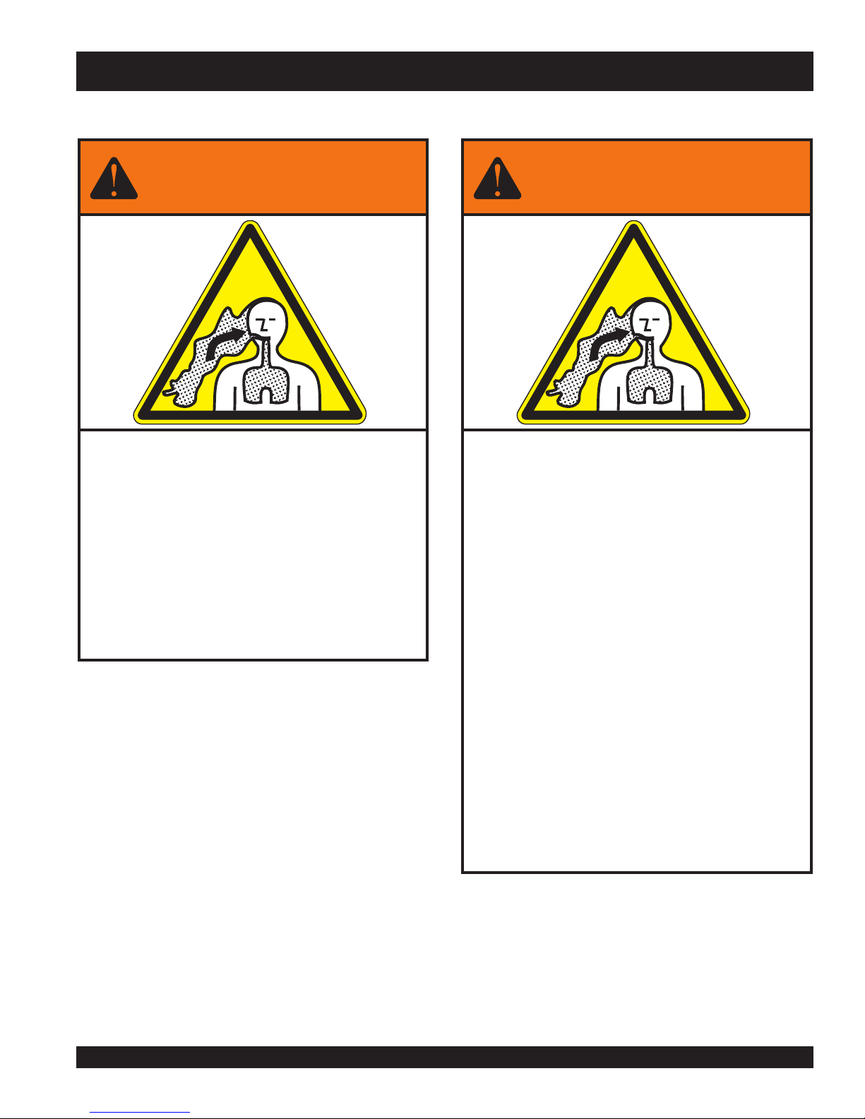
WARNING
SILICOSIS WARNING RESPIRATORY HAZARDS
Grinding/cutting/drilling of masonry, concrete, metal and
other materials with silica in their composition may give
off dust or mists containing crystalline silica. Silica is a
basic component of sand, quartz, brick clay, granite and
numerous other minerals and rocks. Repeated and/or
substantial inhalation of airborne crystalline silica can
cause serious or fatal respiratory diseases, including
silicosis. In addition, California and some other
authorities have listed respirable crystalline silica as a
substance known to cause cancer. When cutting such
materials, always follow the respiratory precautions
mentioned above.
WARNING
Grinding/cutting/drilling of masonry, concrete, metal and
other materials can generate dust, mists and fumes
containing chemicals known to cause serious or fatal
injury or illness, such as respiratory disease, cancer,
birth defects or other reproductive harm. If you are
unfamiliar with the risks associated with the particular
process and/or material being cut or the composition of
the tool being used, review the material safety data
sheet and/or consult your employer, the material
manufacturer/supplier, governmental agencies such as
OSHA and NIOSH and other sources on hazardous
materials. California and some other authorities, for
instance, have published lists of substances known to
cause cancer, reproductive toxicity, or other harmful
effects.
Control dust, mist and fumes at the source where
possible. In this regard use good work practices and
follow the recommendations of the manufacturers or
suppliers, OSHA/NIOSH, and occupational and trade
associations. Water should be used for dust
suppression when wet cutting is feasible. When the
hazards from inhalation of dust, mists and fumes cannot
be eliminated, the operator and any bystanders should
always wear a respirator approved by NIOSH/MSHA for
the materials being used.
Page 4

J-36/M-30 TROWEL— TABLE OF CONTENTS
MQ WHITEMAN J-36/M-30
WALK-BEHIND TROWEL
Table Of Contents ..................................................... 4
Parts Ordering Procedures ....................................... 5
Dimensions ............................................................... 6
Specifications ............................................................ 7
Training Checklist ...................................................... 8
Daily Pre-Operation Checklist ................................... 9
Safety Message Alert Symbols .......................... 10-11
Rules For Safe Operation .................................. 12-13
Operation And Safety Decals .................................. 14
General Information ................................................ 15
Controls and Components ................................. 16-17
Basic Engine ........................................................... 18
Assembly And Installation ..................................19-22
Pre-Inspection .................................................... 23-24
Initial Start-Up ....................................................25-26
Operation ........................................................... 27-28
Options ............................................................... 29-30
Maintenance ...................................................... 31-37
Troubleshooting (Trowel) ................................... 38-39
Troubleshooting (Engine) ........................................ 40
Explanation of Codes in Remarks Column ............. 42
Suggested Spare Parts ........................................... 43
Nameplate And Decals ...................................... 44-45
Standard Handle Assemby ................................ 46-47
Quick Pitch Handle Assembly ............................ 48-51
Basic Unit Assembly ........................................... 52-53
Gearbox Assembly ............................................. 54-55
Engine, 5.5 HP HONDA And 6 HP ROBIN Assy. 56-57
Engine, 9 HP HONDA And 9 HP ROBIN Assy. ... 58-59
Engine, M-30 Trowel, 5.5 HP HONDA Assy........ 60-61
Thrust Collar And Yoke Assembly ...................... 62-63
Spider Assembly ................................................ 64-65
Blades & Pan Assembly ..................................... 66-67
Terms And Conditions Of Sale-Parts ...................... 69
PAGE 4 — J-36/M-30 WALK-BEHIND TROWEL — OPERATION AND PARTS MANUAL — REV. #0 (12/29/06)
NOTE
Specifications and
part numbers are
subject to change
without notice.
Page 5

Effective: January 1st, 2006
Ordering parts has never been easier!
PARTS ORDERING PROCEDURES
Choose from three easy options:
Best Deal!
Order via Internet (Dealers Only):
Order parts on-line using Multiquip’s SmartEquip website!
■
View Parts Diagrams
■
Order Parts
■
Print Specification Information
Goto www.multiquip.com and click on
Order Par ts
to log in and save!
Order via Fax (Dealers Only):
All customers are welcome to order parts via Fax.
Domestic (US) Customers dial:
1-800-6-PARTS-7 (800-672-7877)
Order via Phone:
Non-Dealer Customers:
Contact your local Multiquip Dealer for
parts or call 800-427-1244 for help in
locating a dealer near you.
If you have an MQ Account, to obtain a
Username and Password, E-mail us at:
parts@multiquip.com.
To obtain an MQ Account, contact your
District Sales Manager for more information.
Use the
internet
on
Standard orders
complete part numbers.*
Fax
your order in and qualify for a 2% Discount
on
Standard orders
complete part numbers.*
Domestic (US) Dealers Call:
1-800-427-1244
and qualify for a 5% Discount
for all orders which include
for all orders which include
International Customers
their local Multiquip Representatives for
Parts Ordering information.
Note: Discounts Are Subject To Change
Note: Discounts Are Subject To Change
should contact
When ordering parts, please supply:
❒❒
❒
Dealer Account Number
❒❒
❒❒
❒
Dealer Name and Address
❒❒
❒❒
❒
Shipping Address (if different than billing address)
❒❒
❒❒
❒
Return Fax Number
❒❒
❒❒
❒
Applicable Model Number
❒❒
❒❒
❒
Quantity, Part Number and Description of Each Part
❒❒
NOTE
www.multiquip.com
All orders are treated as
and will ship the same day if received prior
to 3PM PST.
WE ACCEPT ALL MAJOR CREDIT CARDS!
J-36/M-30 WALK-BEHIND TROWEL — OPERATION AND PARTS MANUAL — REV. #0 (12/29/06) — PAGE 5
❒❒
❒
Specify Preferred Method of Shipment:
❒❒
✓
UPS/Fed Ex
■
■
■ Next Day
■
Standard Orders
Priority One
Ground
Second/Third Day
✓ DHL
✓
Tr u ck
Page 6
B
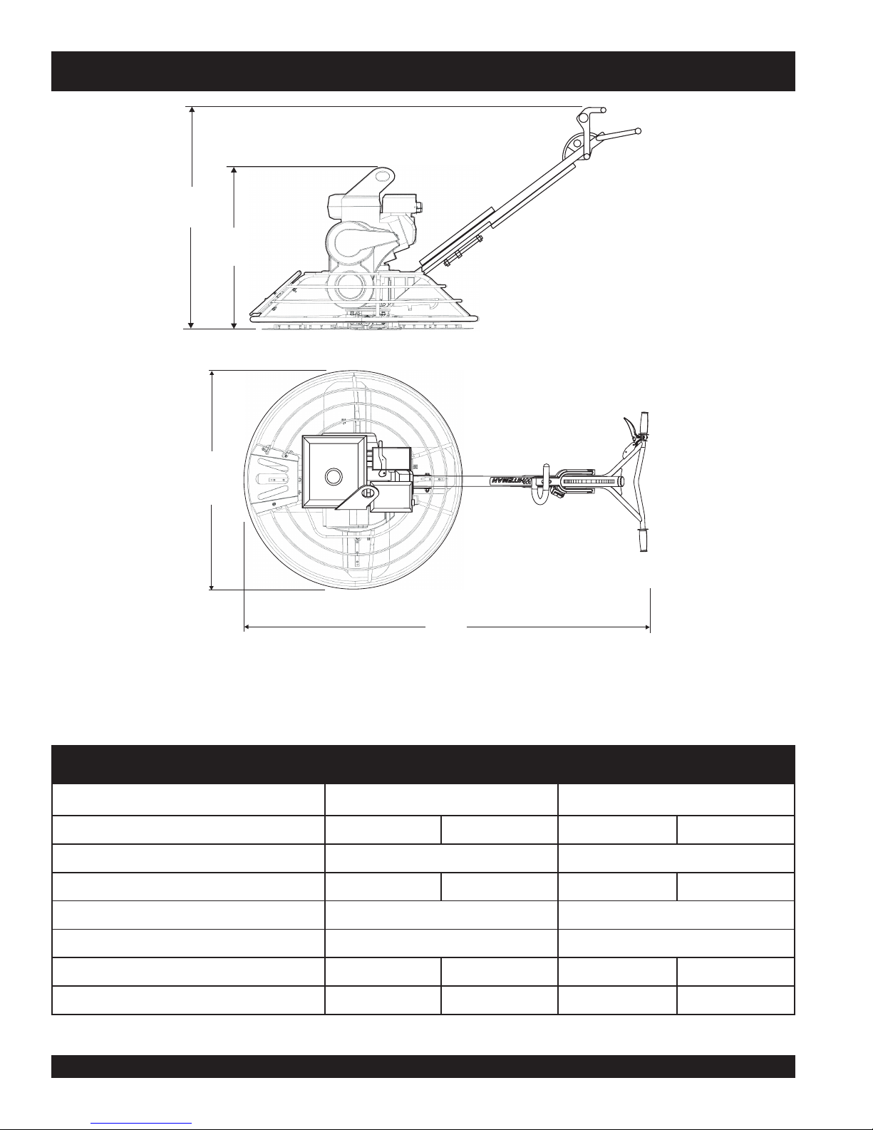
J-36/M-30 TROWEL— DIMENSIONS
A
C
D
Figure 1. J-36/M-30 Trowel Dimensions
sthgieW&snoisnemiDleworT03-M/63-J.1elbaT
63-J03-M
epyTeldnaHdradnatShctiPkciuQdradnatShctiPkciuQ
)elaBgnitfiL(thgieH-A )mm686(.ni72)mm166(.ni62
)reveLtnemegagnE(thgieH-B)mm6101(.ni04)mm7601(.ni24)mm6101(.ni04)mm7601(.ni24
htdiW-C )mm059(.ni4.73)mm708(.ni57.13
htgneL-D )mm0881(.ni47)mm0881(.ni47
niboRPH6/adnoHPH5.5-thgieWgnippihS)gK201(.bl522)gK701(.bl532)gK5.88(.bl591)gK39(.bl502
niboRPH9/adnoHPH9-thgieWgnippihS)gK701(.bl532)gK111(.bl542a/na/n
PAGE 6 — J-36/M-30 WALK-BEHIND TROWEL — OPERATION AND PARTS MANUAL — REV. #0 (12/29/06)
Page 7

J-36/M-30 TROWEL— SPECIFICATIONS
snoitacificepSleworT.2elbaT
ledoM06R63J/55H63J09R63J/09H63JdeepShgiH63-J03-M
sedalBforebmuN4444
retemaiDgniR)mm059(.ni83.73)mm059(.ni83.73)mm059(.ni83.73)mm708(.ni57.13
MPR-rotoR511-06031-06551-09031-06
htdiWhtaP)mm678(ni5.43)mm678(ni5.43)mm678(ni5.43)mm827(ni76.82
1
)mrA/dnaH(noitarbiV
2
)dethgieW(erusserPdnuoS
2
)deetnarauG(erusserPdnuoS
2
s/m0.91
2
s/m0.91
2
s/m0.91
bd901bd901bd901bd901
bd49bd49bd49bd49
2
s/m0.91
NOTE:
1. The vibration level indicated is the maximum RMS (Root
Mean Square) value obtained at the handle grip while
operating the walk-behind trowel at full throttle on steel
plate with blades partially pitched.
ledoMTU061XGADNOHD71-XENIBOR1TU072XGADNOHD72-XENIBOR
,ekorts4delooc-riA
epyT
ekortSXeroB
tnemecalpsiDcc361cc961cc072cc562
enignE
tuptuOxaMMPR0063@.P.H4.5MPR0004@.P.H7.5MPR0063@.P.H9MPR0004@.P.H9
knaTleuF
yticapaC
,VHO,rednilyCelgniS
enilosaGtfahSlatnoziroH
enignE
.ni8.1X.ni07.2
)mm54xmm86(
snollaG.S.U59.0.xorppA
)sretiL6.3(
2. Sound pressure is a weighted measure. It is measured at
the operator's ear position while the walk-behind trowel is
operating at full throttle on concrete in a manner most often
experienced in “
may vary depending upon the condition of the concrete.
enignE
)sretiL6.3(
normal
” circumstances. Sound pressure
)senignE(snoitacificepS.3elbaT
,ekorts4delooc-riA
,VHO,rednilyCelgniS
enilosaGtfahSlatnoziroH
.ni98.1X.ni46.2
)mm84xmm76(
snollaG.S.U59.0.xorppA
,ekorts4delooc-riA
,VHO,rednilyCelgniS
enilosaGtfahSlatnoziroH
enignE
.ni3.2X.ni0.3
)mm85xmm77(
snollaG.S.U95.1.xorppA
)sretiL0.6(
elgniS,ekorts4delooc-riA
latnoziroH,VHO,rednilyC
enignEenilosaGtfahS
.ni63.2X.ni59.2
)mm06xmm57(
snollaG.S.U95.1.xorppA
)sretiL0.6(
leuFenilosaGdedaelnUenilosaGdedaelnUenilosaGdedaelnUenilosaGdedaelnU
yticapaCliOebuL)sretiL6.0(.tQ36.0)sretiL6.0(.tQ36.0)sretiL1.1(.tQ60.1)sretiL0.1(.tQ60.1
lortnoCdeepS
dohteM
dohteMgnitratStratSlioceRtratSlioceRtratSlioceRtratSlioceR
)HxWxL(noisnemiD
thgieWteNyrD
J-36/M-30 WALK-BEHIND TROWEL — OPERATION AND PARTS MANUAL — REV. #0 (12/29/06) — PAGE 7
thgiew-ylFlagufirtneC
epyT
.ni2.31X3.41x3.21
)mm533X263X213(
).gK51(sbl1.33).gK51(sbl1.33).gK52(sbl1.55).gK12(sbl3.64
epyT
thgiew-ylFlagufirtneC
epyT
.ni2.31X49.31x79.11
)mm533X453X403(
thgiew-ylFlagufirtneC
epyT
.ni1.61X9.61x0.41
)mm014X034X553(
thgiew-ylFlagufirtneC
.ni41.61X45.61x28.31
)mm014X024X153(
Page 8

J-36/M-30 TROWEL— TRAINING CHECKLIST
TRAINING CHECKLIST
This checklist will list some of the minimum requirements for
machine maintenance and operation. Please feel free to detach
it and make copies. Use this checklist whenever a new operator
is to be trained or it can be used as a review for more experienced
operator’s.
.ON NOITPIRCSED ?KO ETAD
1 .yletelpmoclaunaMs’rotarepOdaeR
TSILKCEHCGNINIART
2
3 .erudecorpgnileufer,metsysleuF
4 .)gninnurtonenihcam(slortnocfonoitarepO
5 .noitarepohctulc,slortnocytefaS
6 .serudecorppotsycnegremE
7 .enihcamfoputratS
8 .gnirevuenaM
9 .gnihctiP
01 .seuqinhcetgnihsinifetercnoC
11 .enihcamfonwodtuhS
21 .enihcamfognitfiL
dnaenignefognikcehc,stnenopmocfonoitacol,tuoyalenihcaM
.leveldiulfxobraeg
31 .egarotsdnatropsnartenihcaM
Operator _________________________________________ Trainee __________________________________________
COMMENTS:
PAGE 8 — J-36/M-30 WALK-BEHIND TROWEL — OPERATION AND PARTS MANUAL — REV. #0 (12/29/06)
Page 9

J-36/M-30 TROWEL— DAILY PRE-OPERATION CHECKLIST
DAILY PRE-OPERATION CHECKLIST
TSILKCEHCNOITAREPO-ERPYLIAD
1
2
3
4
5
COMMENTS:
diulFxobraeGleveL
.leveLliOenignE
.
sedalBfonoitidnoC
.
.noitarepOhctiPedalB
.noitarepOhctulC
J-36/M-30 WALK-BEHIND TROWEL — OPERATION AND PARTS MANUAL — REV. #0 (12/29/06) — PAGE 9
Page 10
J-36/M-30 TROWEL— SAFETY MESSAGE ALERT SYMBOLS
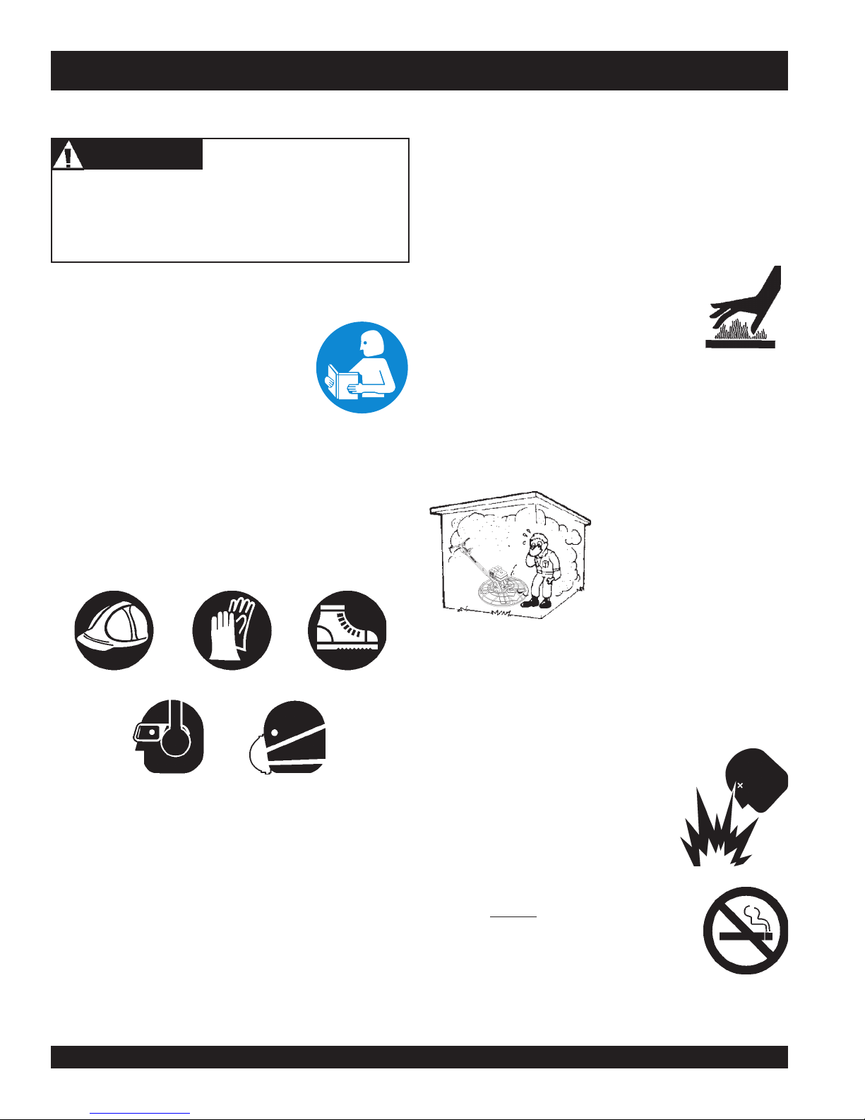
FOR YOUR SAFETY AND THE SAFETY OF OTHERS!
Safety precautions should be followed at all times when operating
this equipment. Failure to read and understand and comply with
the Safety Messages and Operating Instructions could result in
injury to yourself and others.
This Owner's Manual has been developed to provide complete
instructions for the safe and
efficient operation of the MQ
NOTE
Before using this WALK-BEHIND TROWEL, ensure that the
operating individual has read, understands, and complies
with all instructions in this manual.
Whiteman J-36/M-30 TROWEL.
For engine maintenance
information, please refer to the
engine manufacturer's instructions
for data relative to its safe
operation.
HAZARD SYMBOLS
SAFETY MESSAGE ALERT SYMBOLS
The three (3) Safety Messages shown below will inform you
about potential hazards that could injure you or others. The
Safety Messages specifically address the level of exposure to
the operator, and are preceded by one of three words: DANGER,
WARNING, or CAUTION.
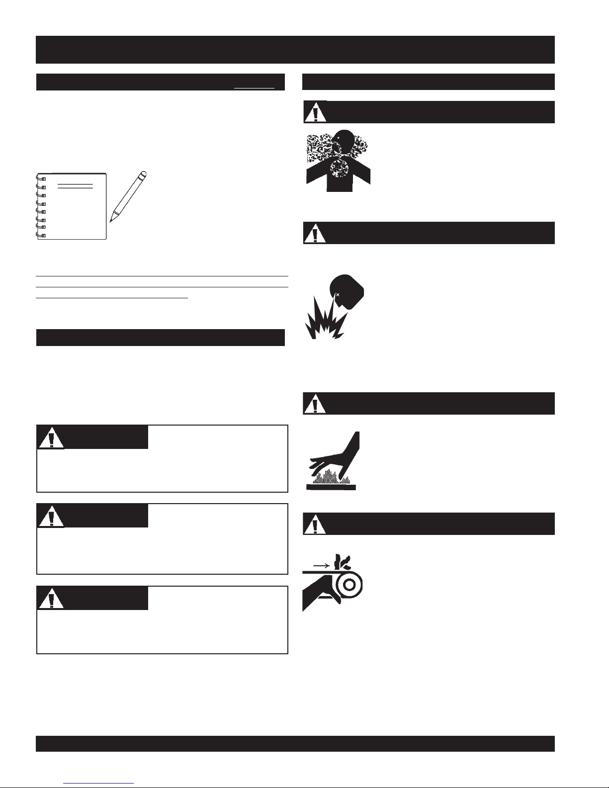
Lethal Exhaust Gases
Engine exhaust gases contain poisonous
carbon monoxide. This gas is colorless and
odorless, and can cause death if inhaled.
NEVER operate this equipment in a confined
area or enclosed structure that does not
provide ample free flow air.
Explosive Fuel
Gasoline is extremely flammable, and its
vapors can cause an explosion if ignited. DO
NOT start the engine near spilled fuel or
combustible fluids. DO NOT fill the fuel tank
while the engine is running or hot. DO NOT
overfill tank, since spilled fuel could ignite if it
comes into contact with hot engine parts or
sparks from the ignition system. Store fuel in
approved containers, in well-ventilated areas
and away from sparks and flames. NEVER
use fuel as a cleaning agent.
Burn Hazards
DANGERDANGER
DANGER
DANGERDANGER
You WILL be
if you DO NOT follow these directions.
WARNINGWARNING
WARNING
WARNINGWARNING
You CAN be KILLED or
you DO NOT follow these directions.
CAUTICAUTI
CAUTION
CAUTICAUTI
You CAN be
these directions.
Potential hazards associated with trowel operation will be
referenced with Hazard Symbols which appear throughout this
manual, and will be referenced in conjunction with Safety
Message Alert Symbols.
KILLED
INJURED
if you DO NOT follow
or
SERIOUSLY INJURED
SERIOUSLY INJURED
if
Engine components can generate extreme heat.
To prevent burns, DO NOT touch these areas
while the engine is running or immediately after
operations. NEVER operate the engine with
heat shields or heat guards removed.
Rotating Parts
NEVER operate equipment with covers, or
guards removed. Keep
and
clothing
prevent injury.
away from all moving parts to
fingers, hands, hair
PAGE 10 — J-36/M-30 WALK-BEHIND TROWEL — OPERATION AND PARTS MANUAL — REV. #0 (12/29/06)
Page 11
J-36/M-30 TROWEL— SAFETY MESSAGE ALERT SYMBOLS
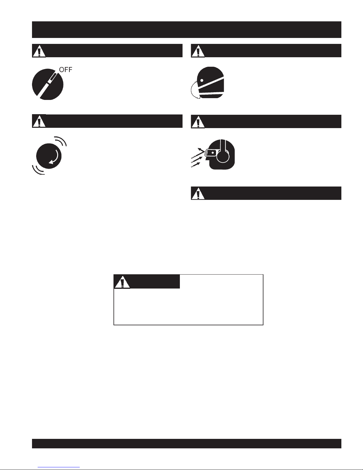
Accidental Starting
ALWAYS place the engine ON/OFF
switch in the OFF position, when the
trowel is not in use.
Over Speed Conditions
NEVER tamper with the factory settings of the
engine governor or settings. Personal injury
and damage to the engine or equipment can
result if operating in speed ranges above
maximum allowable.
Respiratory Hazard
ALWAYS wear approved respiratory protection.
Sight and Hearing hazard
ALWAYS wear approved eye and hearing
protection.
Equipment Damage Messages
Other important messages are provided throughout this manual
to help prevent damage to your trowel, other property, or the
surrounding environment.
CAUTICAUTI
CAUTION
CAUTICAUTI
This walk-behind trowel, other property, or the
surrounding environment could be damaged
if you do not follow instructions.
J-36/M-30 WALK-BEHIND TROWEL — OPERATION AND PARTS MANUAL — REV. #0 (12/29/06) — PAGE 11
Page 12
J-36/M-30 TROWEL — RULES FOR SAFE OPERATION
RULES FOR SAFE OPERATION
WARNINGWARNING
WARNING
WARNINGWARNING
Failure to follow instructions in this manual may lead to serious
injury or even death! This equipment is to be operated by
trained and qualified personnel only! This equipment is for
industrial use only.
■
NEVER operate this equipment when not feeling well due to
fatigue, illness or taking medicine.
■
NEVER operate the trowel under the influence or drugs or
alcohol.
■
Replace nameplate, operation and safety decals when they
become difficult to read.
■
ALWAYS check the trowel for loosened hardware such as
nuts and bolts before starting.
The following safety guidelines should always be used when
operating the J-36/M-30.
SAFETY
■
DO NOT operate or service this equipment
before reading this entire manual. The
manual must be kept available and accessible
to the operator.
■
This equipment should not be operated by persons under the
minimum statutory age limit.
■
NEVER use this machine for any purpose other than those
described in this manual.
■
NEVER operate the trowel without proper protective clothing,
shatterproof glasses, steel-toed boots and other protective
devices required for the job.
■
NEVER touch the hot exhaust manifold, muffler
or cylinder. Allow these parts to cool before
servicing the trowel.
■
High Temperatures – Allow the engine to cool before adding
fuel or performing service and maintenance functions. Contact
hot!
with
■
The engine of this trowel requires an adequate free flow of
cooling air. NEVER operate the trowel in any enclosed or
■
ALWAYS refuel in a well-ventilated area, away from sparks
and open flames.
components can cause serious burns.
narrow area where free flow of the
air is restricted. If the air flow is
restricted it will cause serious
damage to the engine and may
cause injury to people. Remember
the engine gives off
carbon monoxide gas.
DEADLY
■
NEVER use accessories or attachments which are not
recommended by Multiquip for this equipment. Damage to
the equipment and/or injury to user may result.
■
Manufacturer does not assume responsibility for any accident
due to equipment modifications. Unauthorized equipment
modification will void all warranties. Any modification which
could lead to a change in the original characteristics of the
machine should be made only by the manufacturer who shall
confirm that the machine is in conformity with appropriate
safety regulations.
PAGE 12 — J-36/M-30 WALK-BEHIND TROWEL — OPERATION AND PARTS MANUAL — REV. #0 (12/29/06)
■
ALWAYS use extreme caution when working with flammable
liquids. When refueling, STOP the engine and allow it to cool.
■
NEVER operate the trowel in an
explosive atmosphere where fumes
are present, or near combustible
materials. An explosion or fire could
result in severe
death.
■
NEVER
Fire or explosion could result from
vapors
■
Topping-off to filler port is dangerous, as it tends to spill fuel.
■
NEVER use fuel as a cleaning agent.
smoke
, or if fuel is spilled on a
bodily harm or even
around or near the machine.
fuel
hot!
engine.
Page 13
J-36/M-30 TROWEL — RULES FOR SAFE OPERATION
■
NEVER Run engine without air filter. Severe engine damage
may occur. Service air filter frequently to prevent carburetor
malfunction.
■
NEVER place your
while starting or operating this equipment.
■
AVOID wearing jewelry or loose fitting clothing that may snag
on the controls or moving parts as this can cause a serious
injury.
■
ALWAYS keep clear of
operating the trowel.
■
Moving Parts – Shut down the engine before performing
service or maintenance functions. Contact with moving parts
can cause serious injury.
■
ALWAYS check to make sure that the operating area is clear
before starting the engine.
■
NEVER leave the machine
■
ALWAYS be sure the operator is familiar with proper safety
precautions and operations techniques before using trowel.
feet
or
rotating
hands
inside the guard rings
or
moving parts
unattended
while running.
while
■
■
Maintenance Safety
■
■
■
■
■
■
When placing the trowel inside a truck-bed for transport,
always tie-down the trowel.
ALWAYS use proper lifting techniques when moving the
trowel.
NEVER lubricate components or attempt service on a running
trowel.
ALWAYS allow the trowel a proper amount of time to cool
before servicing.
Keep the trowel in proper running condition.
Fix damage to the trowel immediately and always replace
broken parts.
Dispose of hazardous waste properly. Examples of potentially
hazardous waste are used motor oil, fuel and fuel filters.
DO NOT use food or plastic containers to dispose of
hazardous waste.
■
ALWAYS keep the work area well organized.
■
ALWAYS clear the work area of any debris, tools, etc. that
would constitute a hazard while the trowel is in operation.
WARNINGWARNING
WARNING
WARNINGWARNING
ALWAYS check to make sure that the operating area is
clear before starting the engine.
■
No one other than the operator is to be in the working area
when the trowel is in operation.
■
Always observe all applicable compulsory regulations
relevant to environmental protection, especially, fuel storage,
the handling of hazardous substances, and the wearing of
protective clothing and equipment. Instruct the user as
necessary, or, as the user, request this information and
training.
■
ALWAYS store equipment properly when it is not being used.
Equipment should be stored in a clean, dry location out of the
reach of children.
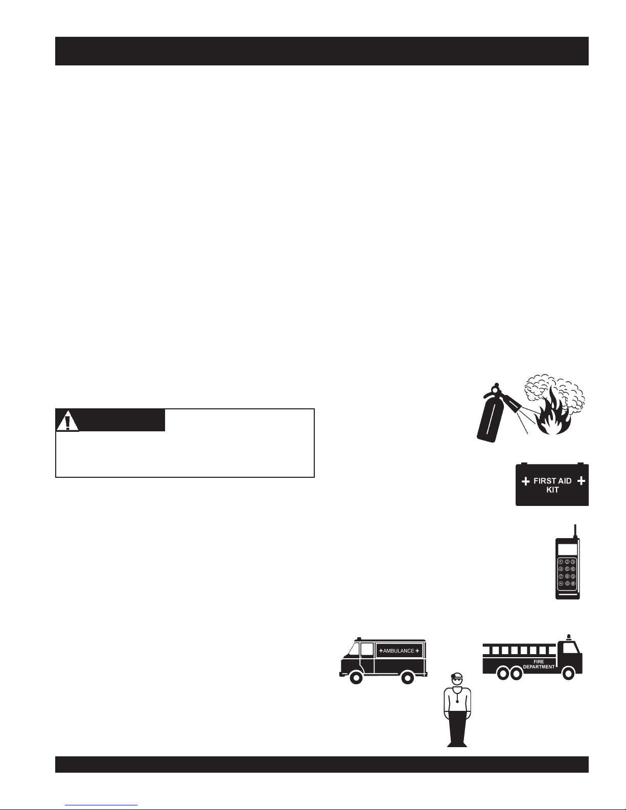
Emergencies
■
■
■
ALWAYS know the location of
the nearest
ALWAYS know the location of the
nearest
In emergencies
nearest phone or
Also know the phone numbers of the nearest
ambulance, doctor
information is invaluable in the case of an
emergency and could keep a serious situation from
becoming a tragic one .
fire extinguisher
first aid kit
.
always
keep a phone on the job site
and
.
know the location of the
.
fire department
. This
Transporting
■
ALWAYS shutdown engine before transporting.
■
Tighten fuel tank cap securely and close fuelcock to prevent
fuel from spilling.
■
Drain fuel when transporting trowel over long distances or
bad roads.
J-36/M-30 WALK-BEHIND TROWEL — OPERATION AND PARTS MANUAL — REV. #0 (12/29/06) — PAGE 13
Page 14

J-36/M-30 TROWEL— OPERATION AND SAFETY DECALS
P/N35168
OPERATION AND SAFETY DECALS
The J-36/M-30 walk-behind trowel is equipped with a number of operation, safety and maintenance decals. Should any of these
decals become unreadable, replacements can be obtained from your dealer.
R
R
SERIES
1
P/N 22070
MODEL
SERIAL NO.
CONTACT
3
PART S
DEPARTMENT
6
P/N 36099 (ISO Blue)
CAUTION
DO NOT LIFT MACHINERY BY GUARD
RING. MAY CAUSE DAMAGE TO
GUARD RING SHOCK MOUNTS
USE LIFT HANDLES ONLY
P/N 1261
9
7
P/N 35137
4
P/N 20816
2
P/N 2942 WHITE TEXT 13”
WARNING
To avoid injury,
you MUST read
and understand
operator’s manual
before using this
machine.
This machine to
be operated by
qualified
personnel only.
Ask for training
as needed.
P/N35137
5
(Quick Pitch Model)
8
U
Q
P
I
T
P/N 12405
P/N: 21455
WARNING!
DO NOT OPERATE HANDLE UNTIL IT IS
SECURELY FASTENED TO POWER TROWEL
& INSTRUCTIONS HAVE BEEN READ
I
C
K
H
C
WARNING
12
ROTATING BLADE
HAZARD
Keep hands
and feet clear
of guard rings.
Stop engine
11
before servicing.
P/N 35168
P/N35168
PAGE 14 — J-36/M-30 WALK-BEHIND TROWEL — OPERATION AND PARTS MANUAL — REV. #0 (12/29/06)
FINISH
Figure 2. Operation and Safety Decals
C
H
T
I
™
P
-
H
A
K
N
C
D
I
U
Q
BOISE, IDAHO USA
U. S. PATENT
C
O
N
P/N 1758
XXXXXXX
C
R
E
L
E
R
E
H
S
I
N
I
T
F
E
13
P/N 11092
PRELOAD TRIM INDICATOR
FINISH
COMBO
J
15
P/N 1735
B
COMBO
10
P/N 20527
14
P/N: 1492
(STANDARD MODEL)
Page 15

J-36/M-30 TROWEL— GENERAL INFORMATION
Intended Use
Operate the J-36/M-30 Trowel, tools and components in
accordance with the manufacturer's instructions. Use of any
other tools for stated operation is considered contrary to
designated use. The risk of such use lies entirely with the user.
The manufacturer cannot be held liable for damages as a result
of misuse.
J-36/M-30 Trowel Familiarization
This walk-behind trowel is designed for the
finishing
Take a walk around the trowel. Take notice of all the major
components (see Figure 3) like the engine, blades, Quick Pitch™
handle, operator presence lever, etc. Check that there is always
oil in the engine.
Read
be found throughout this manual and on the trowel. Keep all
safety information in good, readable condition. Operators should
be well trained on the operation and maintenance of the trowel.
Before using your trowel, test it on a flat watered down section of
finished concrete that is free of any debris and other objects.
This trial test run will increase your confidence in using the trowel
and at the same time it will familiarize you with the trowel’s
controls. In addition you will understand how the trowel handles
under actual conditions.
Engine
This trowel is available with a 5.5 or 9 HP
engine, or a 6 or 9 HP
engine owner’s manual for instructions regarding the operation
and maintenance of your engine. Please contact your nearest
Multiquip Dealer for a replacement should the original manual
disappear or otherwise become unusable.
of concrete slabs.
all the safety instructions carefully. Safety instructions will
ROBIN
gasoline engine. Refer to the
floating
HONDA
and
gasoline
Spider
The vertical output shaft of the gearbox connects to a cast hub
called the
that are used for attachment of blades or other accessories.
Remember as the gearbox output shaft rotates so does the spider
assembly.
Guard Ring
This unit is equipped with a safety guard ring. It is designed to
help protect items from coming into contact with the rotating
blades while in operation.
Blades
The blades of the trowel finish the concrete as they are rotated
around the surface. This trowel comes equipped with four
combination
spaced in a radial pattern and attached to vertical rotating
shaft by means of a
Safety Stop Switch
In the event of a trowel runaway condition (operator releases
the handlebars), the
stop the engine and bring the trowel to a halt
Operator Presence Lever (Optional Feature)
If equipped with the optional
the event of a trowel runaway condition (operator releases
the handle), the
stop switch
to a halt.
spider
. The spider has 4 arms that extend outward
(8 in./203mm wide) blades per rotor equally
spider assembly.
centrifugal safety stop switch
operator presence lever
operator presence lever
which will stop the engine and bring the trowel
CAUTIONCAUTION
CAUTION
CAUTIONCAUTION
signals the
will
, in
safety
Drive System
Power is transferred from the engine to the gearbox input shaft
via a V-belt pulley drive system. The pulley engages using a
centrifugal clutch. See Parts section of this manual.
Gearbox
gearbox
The
to the
of the trowel and is equipped with two shafts (input and output).
is located beneath the engine and transfers power
spider
assembly. The gearbox controls the rotational speed
J-36/M-30 WALK-BEHIND TROWEL — OPERATION AND PARTS MANUAL — REV. #0 (12/29/06) — PAGE 15
NEVER attempt to
the assistance of another person to help lift the trowel .
Training
For proper training, please use the “TRAINING CHECKLIST”
located in the front of this manual (Page 8). This checklist will
provide an outline for an experienced operator to provide training
to a new operator
lift
the trowel by yourself. ALWAYS get
Page 16
J-36/M-30 TROWEL— CONTROLS AND COMPONENTS
FINISH
COMBO
PRELOADTRIM
INDICATOR
FINISH
COMBO
12
11
6
3
5
6
2
QUICK PITCH ™
10
HANDLE
1
15
8
9
7
O
B
M
O
O
B
M
O
C
J
PRELOADTRIM INDICATOR
H
IS
IN
F
C
B
H
S
I
N
I
F
13
4
19
14
PAGE 16 — J-36/M-30 WALK-BEHIND TROWEL — OPERATION AND PARTS MANUAL — REV. #0 (12/29/06)
17
16
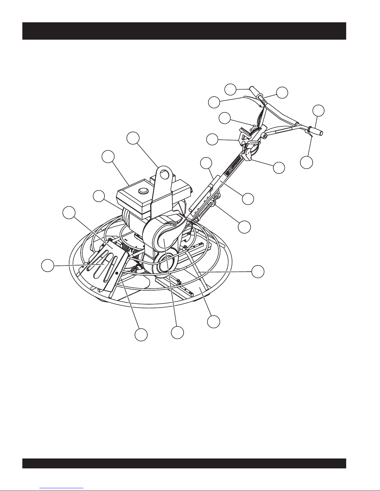
Figure 3. Controls And Components
18
Page 17

J-36/M-30 TROWEL— CONTROLS AND COMPONENTS
Figures 3 shows the location of the basic controls or components,
for the J-36/M-30 trowel. Listed below is a brief explanation of
each control or component
1. Quick Pitch™ Control Handle – To adjust the pitch of
the blades, grasp the handle then squeeze and either move
the handle forward or backward to achieve the desired
blade pitch.
2. Handlebar Adjuster – Change the angle/height of the
handle bars by loosening star wheel, adjust handlebars to
desired location, tighten starwheel firmly to hold handlebars
in that position.
3. Handle Bar – When operating the trowel, place both hands
on each grip to maneuver the trowel.
4. Recoil Starter Housing – Automatically spools the recoil
starter rope when using to start the engine.
5. Operator Presence Lever (Optional Feature) – If
equipped with the optional
in the event of a trowel runaway condition (operator
releases the handle), the
signals the
engine and bring the trowel to a halt.
safety stop switch
operator presence lever
operator presence lever
which will stop the
15. Engine – This trowel uses a Honda or a Robin gasoline
engine.
16. Trowel Arm – NEVER operate the trowel with a bent, broken
or out of adjustment trowel arm. If the blades show uneven
wear patterns or some blades wear out faster than others,
the trowel arm may need to be adjusted. Use the trowel
arm adjustment tool P/N 1817 to adjust the trowel arms.
17. Blades – This trowel is equipped with combination blades.
These blades are versatile and should take care of most
troweling needs. In addition float discs can be attached to
the trowel arms that will allow the trowel to float on "wet"
concrete.
18. V-Belt Cover – Remove this cover to gain access to the Vbelt. NEVER operate the trowel with this cover removed.
19. Pre-Load Adjuster (Quick Pitch Handle) – Handle PreLoad can be adjusted to the specific trowel that the handle
,
is affixed to. For the J-36 and M-30 Series, the adjustment
screw should be set with the arrow aligned to the letter "J".
6. Hand Grip – Replace hand grips when they become worn
or damaged.
7. Centrifugal "Kill" Switch – In the event the operator loses
control of the trowel, this switch will shut-down the engine.
8. Auxiliary Lifting Tube - Use this tube to lift the trowel onto
a slab. Tube is to be inserted into socket located in front of
the gearbox.
9. Throttle Lever – Controls engine speed. Returns engine
to idle when released.
10. Trowel Lifting Point – Insert the auxiliary lifting tube here.
See Figure 23.
11. Access Door – Hinged door allows access to the blade
area.
12. Lifting Tube Access Slot – Insert the auxillary lifting tube
here.
13. Main Tube - When disassembling components inside the
tube exercise extreme CAUTION! Tube is spring-loaded,
severe injury could result if not disassembled correctly.
14. Guard Ring- NEVER! put hands or feet inside guard ring
while the machine is running.
J-36/M-30 WALK-BEHIND TROWEL — OPERATION AND PARTS MANUAL — REV. #0 (12/29/06) — PAGE 17
Page 18
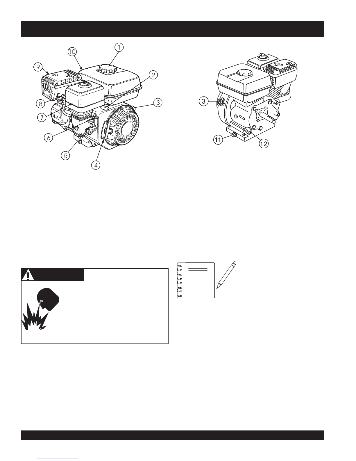
J-36/M-30 TROWEL— BASIC ENGINE
Figure 4. Engine Controls and Components
INITIAL SERVICING
The engine (Figure 4) must be checked for proper lubrication and
filled with fuel prior to operation. Refer to the manufacturer's engine
manual for instructions & details of operation and servicing. The
engine shown above is a HONDA engine, operation for other
types of engines may vary somewhat.
1. Fuel Filler Cap – Remove this cap to add unleaded
gasoline to the fuel tank. Make sure cap is tightened
securely. DO NOT over fill.
DANGER
Adding fuel to the tank should be done only
when the engine is stopped and has had an
opportunity to cool down. In the event of a fuel
spill, DO NOT attempt to start the engine until
the fuel residue has been completely wiped
up, and the area surrounding the engine is dry.
2. Throttle Lever – Used to adjust engine RPM speed (lever
SLOW
advanced forward
FAST
).
3. Engine ON/OFF Switch –
OFF
starting,
4. Recoil Starter (pull rope) – Manual-starting method. Pull
the starter grip until resistance is felt, then pull briskly and
smoothly.
position stops engine operation.
, lever back toward operator
ON
position permits engine
5. Fuel Valve Lever – OPEN to let fuel flow, CLOSE to stop
the flow of fuel.
6. Choke Lever – Used in the starting of a cold engine, or in
cold weather conditions. The choke enriches the fuel
mixture.
7. Air Cleaner – Prevents dirt and other debris from entering
the fuel system. Remove wing-nut on top of air filter
cannister to gain access to filter element.
NOTE
8. Spark Plug – Provides spark to the ignition system. Set
spark plug gap according to engine manufacturer's
instructions. Clean spark plug once a week.
9. Muffler – Used to reduce noise and emissions.
10. Fuel Tank – Holds unleaded gasoline. For additional
information refer to engine owner's manual.
11. Oil Drain Plug – Remove this plug to remove oil from the
engine's crankcase.
12. Dipstick/Oil Filler Cap – Remove this cap to determine if
the engine oil is low. Add oil through this filler port as
recommended in Table 4.
Operating the engine without an air
filter, with a damaged air filter, or a
filter in need of replacement will
allow dirt to enter the engine,
causing rapid engine wear.
PAGE 18 — J-36/M-30 WALK-BEHIND TROWEL — OPERATION AND PARTS MANUAL — REV. #0 (12/29/06)
Page 19
J-36/M-30 TROWEL — ASSEMBLY AND INSTALLATION
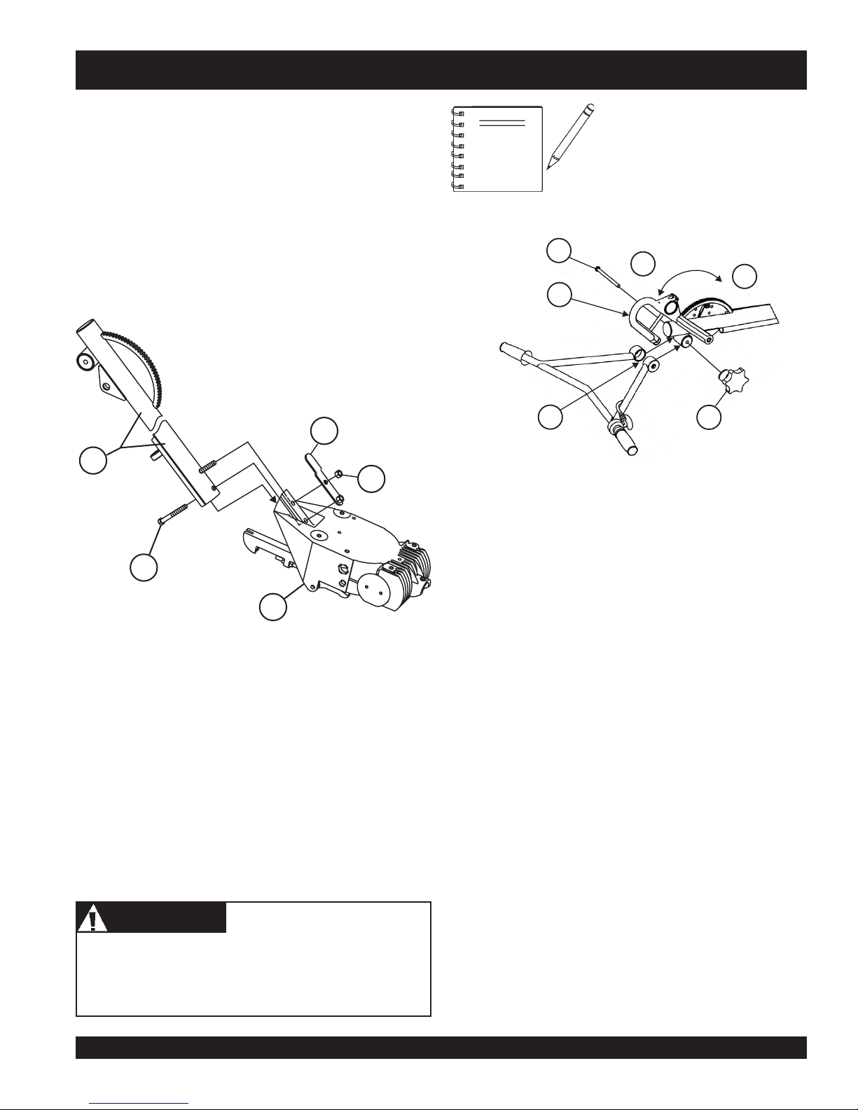
Assembly and Installation
Before the trowel can be put into operation there are some
components that must be installed before the trowel can be used.
This section provided general instructions on how to install those
components. Instruction sheet P/N 20485 provides further details
for the handle assembly.
Handle Tube Installation (All Models)
1. Install the
The mounting hardware should be contained in the shipping
container.
handle tube
to the gearbox as shown in (Figure 5).
PIVOT PITCH HANDLE
BACK AS SHOWN TO
RELIEVE SPRING TENSION
(QUICK PITCH MODEL)
NOTE
HEX SCREW 3/8-16 x 5
5
1
3
1 Pivot Pitch Handle (Pivot back to
2 Hex Screw (3/8 - 16 x 5)
3 Full Pitch
4
2
4 No Pitch
5 Spread Slightly to Install
6 Hand Wheel
Considerable force may be
required when moving the QuickPitch™ T-handle forward or
backward.
2
PITCH
1
SPREAD
5
SLIGHTLY
TO INSTALL
relieve spring tension)
FULL
3
HAND WHEEL
6
NO
4
PITCH
1 Main Handle (Tube)
2 Gearbox
3 3/8" Hex Nut
4 3/8" Hex Head Screw
Figure 5. Handle Tube Installation
2. Pivot the
relax the spring inside the handle tube. Spread the handle
bar ends just enough to engage the teeth on the handle
tube. Attach the hand wheel assembly, position handlebar
to desired location, and tighten hand wheel firmly.
The Quick-Pitch™ handle is spring loaded, personal injury
or damage could result from improper handling or
installation. Be careful when installing this component.
T-handle
CAUTIONCAUTION
CAUTION
CAUTIONCAUTION
back (full pitch) (Figure 6). This will
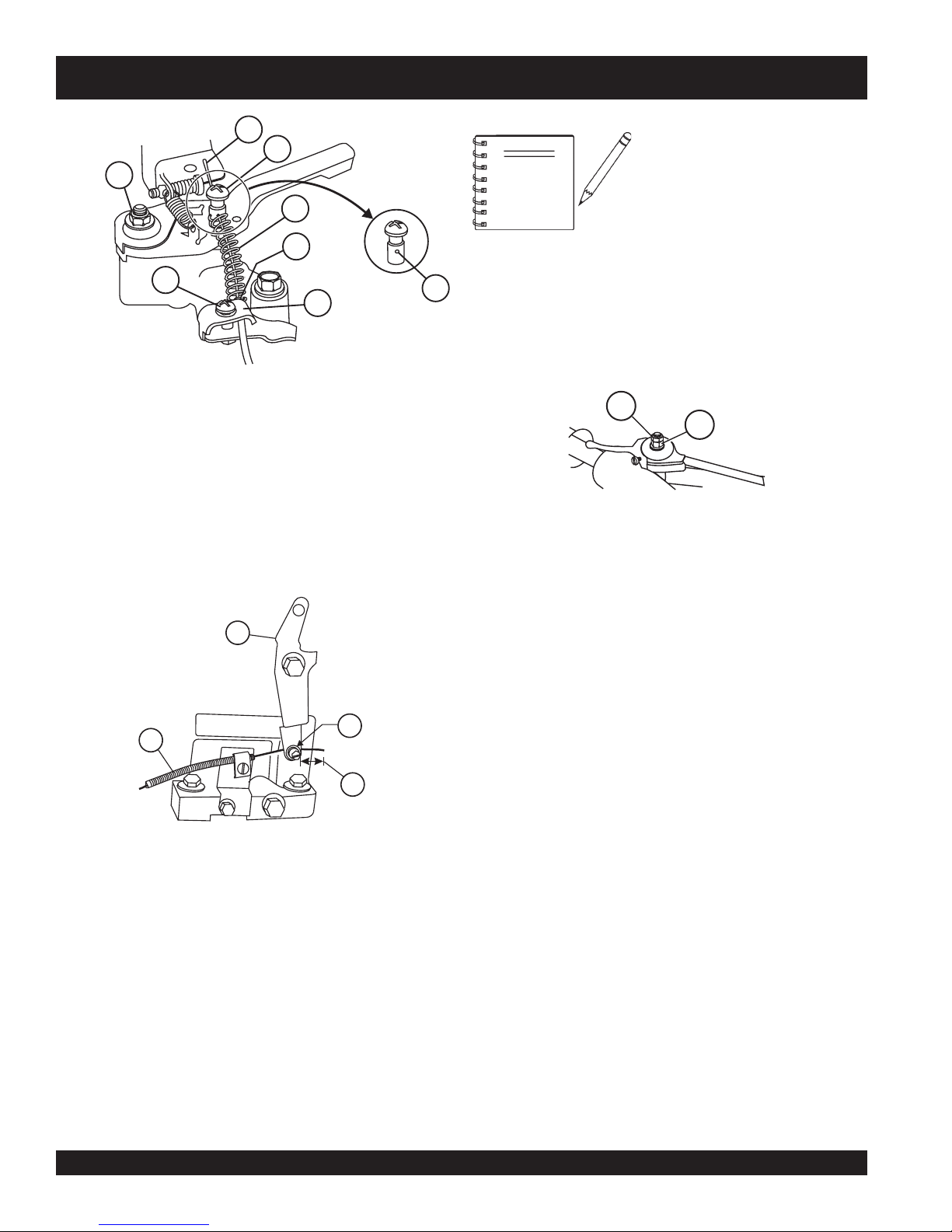
Throttle Cable Installation
1. Uncoil the throttle cable and housing.
2. Feed the throttle cable through the cable housing.
3. Connect the throttle cable to the engine. (Figure 7), HONDA
Figure 6. Handlebar Installation
and (Figure 8), ROBIN. There should be a piece of wire
installed on the trowel to show where to route the throttle
cable. Route cable end (item 2) through the spring (item 4)
and swivel stop (item 6). When connecting the cable housing,
make sure that no more than
housing (item 5) protrudes past the housing clamp (item 7)
on the engine.
1/4" (6.4mm)
of the cable
J-36/M-30 WALK-BEHIND TROWEL — OPERATION AND PARTS MANUAL — REV. #0 (12/29/06) — PAGE 19
Page 20
J-36/M-30 TROWEL — ASSEMBLY AND INSTALLATION
2
3
1
4
5
8
7
1 Adjuster Nut
2 Cable End
3 Swivel Stop
4 Idle Return Spring
5 Cable Housing (End)
6 Swivel Stop Hole
7 Cable Housing Clamp
8 Clamp Screw
Figure 7. Throttle Cable Connection (HONDA)
If the throttle lever does not return
to the "neutral" position with
NOTE
7. These are general instructions. Installation of the throttle
6
cable may vary for different engine configurations. Please
look for more detailed instructions inside the box containing
the handle. These more detailed instructions should provide
adequate guidance for installing.
throttle backed off, loosen
adjuster nut (item 1) 1/2 turn at a
time, tighten and recheck.
Readjust throttle tension as
necessary.
2
1
1 Adjusting Nut
2 Locking Nut
Figure 9. Safety Wire Connection
2
3
1
4
1 Throttle Cable
2 Engine Throttle Lever
3 Place Throttle Cable Here
4 1/4" (6.4mm) Deflection
Figure 8. Throttle Cable Connection (ROBIN)
4. Tighten cable clamp screw (item 8) and swivel stop screw
(item 3).
5. After the cable has been installed on the engine, adjust
and tighten operator position of the handle to lock the
throttle cable at the proper length.
6. Adjust cable tension. Loosen the lock nut on the throttle
cable receiver (Figure 9) and loosen or tighten the nut
below it. Retighten the lock nut.
Handle Height Adjustment
If handle height adjustment is desired, a handle wedge kit can be
purchased for your trowel by ordering P/N 2576 from your Multiquip
dealer. These wedges are placed between the handle and the
gearbox to adjust the operating height of the handle. This kit
comes complete with wedges, new bolts and installation
instructions. This will move your operating handle position up or
down approximately 3” (76mm).
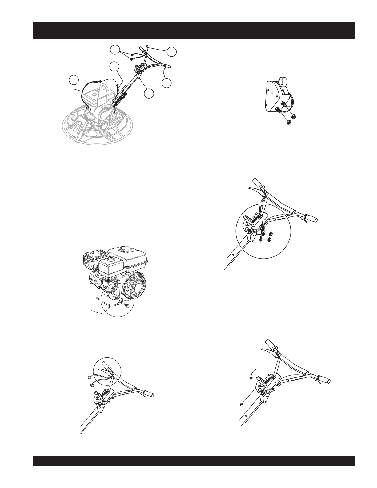
Operator Presence Switch Installation (Optional)
Your adjustable handle utilizes an "Operator Presence Switch"
that shuts the engine down once the Operator Presence Lever
is released. To install the lever, switch, and associated wiring,
perform the following procedures:
1. Ensure the handle tube is properly installed onto the
gearbox, handlebars onto the handle tube, and throttle
cable installed according to the instruction sheet provided
with the handle.
2. Connect the Safety Stop Wire from the Safety Stop Switch
to the tail wire on the engine. (Figure 10)
PAGE 20 — J-36/M-30 WALK-BEHIND TROWEL — OPERATION AND PARTS MANUAL — REV. #0 (12/29/06)
Page 21
FINISH
C
OMBO
PRELOADTRIM
INDICATOR
FINISH
COMBO
J-36/M-30 TROWEL — ASSEMBLY AND INSTALLATION
1
2
4
3
O
B
R
M
O
C
TO
A
C
I
B
D
IN
H
S
I
N
I
IM
F
R
T
O
B
D
M
O
A
C
O
L
E
J
R
P
H
S
I
N
I
F
6
5
1 Operator Presence Wiring (Option)
2 Operator Presence Lever (Option)
(Temporary Positioning for Shipping)
3 Tail Wire From Engine
4 Safety Stop Wire From Switch
5 Safety Stop Switch
6 Throttle Lever
Figure 10. Safety Wire Connection
5. Remove one 7mm nut from each of the terminals on the
Safety Stop Switch. (Leave the existing two wires to the
switch connected.) (Figure 13).
Figure 13. Safety Stop Switch Connection
6. Connect the two wires from the Operator Presence Lever
to the Safety Stop Switch terminal lugs. (one per lug; either
position). Re-install and tighten the nuts. (Figure 14).
3. Install the ground wire to the engine, (Honda engine shown,
Figure 11).
Ground Wire
from handle
Pitch Cable Installation
1. Expose the pitch cable to maximum by adjusting the handle
pitch to the "no pitch" position. Pivot the pitch handle forward
Figure 11. Ground Wire Connection
or no pitch, (Figure 15).
4. If so equipped, re-position the Operator Presence Lever
on the handlebars, (Figure 12).
Figure 14. Wiring Connection
NO PITCH
FORWARD
Figure 12. Repositioning the Lever
J-36/M-30 WALK-BEHIND TROWEL — OPERATION AND PARTS MANUAL — REV. #0 (12/29/06) — PAGE 21
Figure 15. "No Pitch" Position
Page 22

FINISH
COMBO
PRELOADTRIM
INDICATOR
FINISH
COMBO
J-36/M-30 TROWEL — ASSEMBLY AND INSTALLATION
2. Lock the spring in the compressed position, by releasing
the blade pitch adjustment trigger.
1 Yoke
2 Thread Cable End Through Yoke Eyelet
3. Remove one brass set nut from the blade pitch cable end
3 Use a Wrench to Tighten First Brass Set
as shown in (Figure 16).
4. Thread the second brass set nut towards the cable as far
4 Tighten Second Brass Set Nut Against
as possible.
Pre-load Adjustment
1. After the Quick-Pitch™ handle has been installed on the
1
trowel, spring pre-load adjustment will be required.
2. Locate the adjustment screw on the underside of the handle
tube (Figure 18).
2
3
1 Blade Pitch Cable
2 Remove First Brass "Set" Nut
3 Thread Second Brass "Set" Nut
to End of Cable
Figure 16. Blade Pitch Cable
5. Insert the cable end through the yoke eyelet (Figure 17)
Tighten the first brass set nut by hand to remove all the
slack from the cable.
Nut Against Yoke Boss
Yoke Boss
Figure 17. Cable Yoke Attachment
1
PRELOAD TRIM INDICATOR
FINISH
FINISH
COMBO
J
COMBO
B
2
O
B
M
O
C
B
H
IS
IN
F
O
B
M
O
C
J
PRELOADTRIM INDICATOR
ISH
IN
F
3
6 Using a wrench, tighten the second brass set nut up against
the yoke boss. This will lock the cable in place.
7. Use a wrench and finish tightening the first brass set nut up
against the yoke boss.
1 Alignment Decal
2 Align This Arrow With The Letter "J"
Combo On Decal
3 Adjustment Screw
Figure 18. Pre-load Adjustment
1
decal
3. A
has been placed on the side of the handle tube to
assist the user in the adjustment of the spring.
2
4
3
4. Align the
COMBO
arrow
on the
Walk-Behind trowel.
on the adjustment screw with the letter "J"
decal
. The letter "J" stands for J-36/M-30
5. Test the pitch control operation and adjust if necessary.
PAGE 22 — J-36/M-30 WALK-BEHIND TROWEL — OPERATION AND PARTS MANUAL — REV. #0 (12/29/06)
Page 23

CAUTIONCAUTION
CAUTION
CAUTIONCAUTION
ALWAYS wear approved eye and
hearing protection before operating the
trowel.
NEVER place hands or feet inside the
guard rings while the engine is running.
ALWAYS shut the engine down before
performing any kind of maintenance
service on the trowel.
J-36/M-30 TROWEL— PRE-INSPECTION
Figure 19. Engine Oil Dipstick (Removal)
3. Insert and remove the dipstick without screwing it into the filler
neck. Check the oil level shown on the dipstick.
Before Starting
1. Read safety instructions at the beginning of manual.
2. Clean the trowel, removing dirt and dust, particularly the
engine cooling air inlet, carburetor and air cleaner.
3. Check the air filter for dirt and dust. If air filter is dirty, replace
air filter with a new one as required.
4. Check carburetor for external dirt and dust. Clean with dry
compressed air.
5. Check fastening nuts and bolts for tightness.
Engine Oil Check
1. To check the engine oil level, place the trowel on secure
level ground with the engine stopped.
2. Remove the filler dipstick from the engine oil filler hole
(Figure 19) and wipe clean.
4. If the oil level is low (Figure 20), fill to the edge of the oil filler
hole with the recommended oil type (Table 4).
NOTE
Reference manufacturer engine
manual for specific servicing
instructions.
Figure 20. Engine Oil Dipstick (Oil Level)
J-36/M-30 WALK-BEHIND TROWEL — OPERATION AND PARTS MANUAL — REV. #0 (12/29/06) — PAGE 23
epyTliO.4elbaT
nosaeS erutarepmeT epyTliO
remmuS rehgiHroC°52 03-W01EAS
llaF/gnirpS C°01~C°52 02/03-W01EAS
retniW rewoLroC°0 01-W01EAS
Page 24

J-36/M-30 TROWEL— PRE-INSPECTION
V-Belt Check
DANGERDANGER
DANGER
DANGERDANGER
EXPLOSIVE FUEL!
Motor fuels are highly flammable and can
be dangerous if mishandled. DO NOT
smoke while refueling. DO NOT attempt to
hot!
refuel the trowel if the engine is
running
Fuel Check
1. Remove the gasoline cap located on top of fuel tank.
2. Visually inspect to see if fuel level is low. If fuel is low, replenish
3. When refueling, be sure to use a strainer for filtration. DO
Gearbox Oil
1. Determine if the
.
with unleaded fuel.
NOT top-off fuel. Wipe up any spilled fuel.
gearbox
plug located on the side of the gearbox. (Figure 21) This
plug will be marked by the "
of the lubrication oil should be to the bottom of the fill plug.
1
oil is low by removing the oil
check
or
" decal. The correct level
A worn or damaged V-belt can adversely affect the performance
of the trowel. If a V-belt is defective or worn simply replace the Vbelt as outlined in the maintenance section of this manual.
Belt Guard Check
Check for damage, loose or missing hardware.
Blade Check
Check for worn or damaged blades. Check to see if one blade is
worn out while the others look new. If this is the case there could
be a blade pitch problem. Refer to the maintenance section of
this manual for blade pitch adjustment procedure. Replace any
worn blades.
CONTROLS
Safety-Stop "Kill" Switches
This trowel has been equipped with a safety "kill" switch. This
switch should be tested every time the engine is started.
WARNINGWARNING
WARNING
WARNINGWARNING
NEVER disable or disconnect the safety "kill" switch. It is
provided for operator safety. Injury may result if it is disabled,
disconnected or improperly maintained.
Centrifugal Type "Kill" Switch
2
3
1 Gear Box
2 Oil Sight/Fill Plug
3 Drain Plug
Figure 21. Gearbox
2. If lubrication oil begins to seep out as the drain plug is
being removed, then it can be assumed that the gearbox
has a sufficient amount of oil.
3. If lubrication oil does not seep out as the drain plug is
being removed, fill with type ISO 680 (Whiteman P/N 10139)
gearbox lubricant oil until the oil filler hole overflows.
CAUTIONCAUTION
CAUTION
CAUTIONCAUTION
Disconnect the spark plug wire from the spark plug and
secure away from the engine before performing
maintenance or adjustments on the machine.
(Figure 22) The switching mechanism of this switch should
operate freely and should
the switch in the OFF position, the engine should not start or run.
The purpose of this switch is to stop the engine in a runaway
situation, (i.e. the operator releasing the handle during operation).
always
3
2
1 "Kill" Switch (Safety Stop)
2 "ON" Position
3 "OFF" Position
Figure 22. Centrifugal "Kill" Switch
be kept in this condition. With
1
PAGE 24 — J-36/M-30 WALK-BEHIND TROWEL — OPERATION AND PARTS MANUAL — REV. #0 (12/29/06)
Page 25

CAUTIONCAUTION
FINISH
COMBO
PRELOADTRIM
INDICATOR
FINISH
COMBO
CAUTION
CAUTIONCAUTION
J-36/M-30 TROWEL — INITIAL START-UP
This section is intended to assist the operator with the initial
start-up of the walk-behind trowel. It is extremely important
that this section be read carefully before attempting to use
the trowel in the field.
DO NOT use your trowel until this section is thoroughly
understood.
DO NOT attempt to operate the trowel until the Safety,
General Information and Inspection sections of this manual
have been read and thoroughly understood. Depending on
engine manufacturer, operating steps may vary. See engine
manufactures operating manual. The following start-up
procedure makes reference to a HONDA Engine (Manual
Start).
Lifting the Trowel Onto a Slab
Extra care should be taken when lifting the trowel off the ground.
Serious damage to the machine or personal injury could be
caused by dropping a trowel.
The trowel must be stabilized by the person carrying the
operator’s handle
CAUTIONCAUTION
CAUTION
CAUTIONCAUTION
the handle may swing around and
damage to the trowel and bodily injury.
Figure 23. Lifting the Trowel
CAUTIONCAUTION
CAUTION
CAUTIONCAUTION
(Figure 23). If it is not stabilized properly
1
2
O
B
M
R
O
C
TO
B
ICA
D
IN
H
IS
IN
F
IM
R
T
O
B
M
O
C
AD
ELO
J
R
P
H
IS
IN
F
3
flip
the trowel, thus causing
heavy
and
The trowel is
awkward
proper heavy lifting procedures and DO NOT
by the guard rings.
to move around. Use
lift the trowel
Lifting Bale
The lift bale (Item 10, page 17), provides an optimal lift point for
moving the trowel.
Auxiliary Lifting Tube
Remove the auxiliary lifting tube located on top of the main handle.
Insert the tube into the socket located on the opposite side of the
gearbox (Figure 23) from the handle.
up onto a building with a crane.
Using a
crane
recommended, and is perfectly safe for the machine. Extra care
should be taken when lifting the machine off the ground, however.
Lift bales or forklift
to move a machine with a lift bale is highly
can be used to lift a trowel
Serious damage to the machine or personal injury could be
Make sure that the hole in the tube engages with the pin in the
caused by dropping a trowel.
socket. With one person lifting from the main handle, and another
lifting from the auxiliary lifting tube pick up the machine to move
onto a slab.
J-36/M-30 WALK-BEHIND TROWEL — OPERATION AND PARTS MANUAL — REV. #0 (12/29/06) — PAGE 25
Page 26

J-36/M-30 TROWEL — INITIAL START-UP
Starting the Engine (
1. Place the engine
position.
Figure 24. Engine Fuel Valve Lever
3. Place the
position. For models that use this feature.
centrifugal "kill" switch
HONDA
fuel valve lever
engine)
(Figure 24) to the "ON"
(Figure 25) in the "ON"
4. Place the
5. Grasp the starter grip (Figure 27) and slowly pull it out. The
resistance becomes the hardest at a certain position, corresponding to the compression point. Pull the starter grip briskly
and smoothly for starting.
Choke Lever
Figure 26. Engine Choke Lever
(Figure 26) in the "
OPEN
" position
CAUTIONCAUTION
CAUTION
CAUTIONCAUTION
NEVER disable or disconnect the centrifugal kill switch. It is
provided for the operators’ safety and injury may result if it is
disabled, disconnected or improperly maintained.
OFF
6. If the engine has started, slowly return the choke lever
ON
“KILL” SWITCH
(SAFETY-STOP)
Figure 25. Centrifugal "Kill" Switch
(Figure 26) to the
started repeat steps 1 through 5.
Before the trowel is placed into operation, run the engine for
7.
several minutes. Check for fuel leaks, and noises that would
associate with a loose guard ring and/or covers.
Figure 27. Starter Grip
CLOSED
position. If the engine has not
PAGE 26 — J-36/M-30 WALK-BEHIND TROWEL — OPERATION AND PARTS MANUAL — REV. #0 (12/29/06)
Page 27

J-36/M-30 TROWEL — OPERATION
8.
To begin troweling, while holding onto the handlebar grips,
grasp and pull in the Operator Presence Lever if so equipped.
(Figure 28).
RUN
Maneuvering the Trowel
1.
Get into the operator’s position behind the handle. With a
secure foothold and a firm grasp on the handles slowly
increase the engine speed until the desired blade speed is
obtained.
2. To maneuver the trowel, gently lift up on or press down on the
STOP
Figure 28. Operator Presence Lever (Run Position)
(Optional Feature)
main trowel handle. To move the machine to the operator’s
left,
down
3. The best method for finishing concrete is to slowly walk
backwards (Figure 31) with the trowel, guiding the trowel
from side to side. This will cover all footprints on wet concrete.
4. Remember that if you let go of the trowel, just step away and
let the trowel come to a complete stop before trying to recover
the trowel.
Stopping The Engine
1. Move the throttle lever to the IDLE or SLOW position and
The following steps are intended as a basic guide to machine
operation, and are not to be considered a complete guide to
concrete finishing. We suggest that all operators (experienced
and novice) read “
Concrete Institute, Detroit, Michigan
section of this manual for more information.
Slabs on Grade
” published by the
. Read the “Training”
American
run the engine for three minutes at low speed.
2. After the engine
“OFF” position (Figure 30).
lift up
on the handle, to move machine to the right,
on the handle.
cools
, turn the engine start/stop switch to the
push
Pitching The Blades
Quick Pitch Handle
1. To pitch the blades upwards using the
T-handle
and pull the
the
, (Figure 29) simply squeeze the trigger lock
T-handle
T-handle
towards the engine will cause the blades
towards the operator. Pushing
"Quick-Pitch
™"
Figure 30. Engine ON/OFF Switch (OFF Position)
to lay flat.
3. Close the
fuel shut- off valve
(Figure 31) by moving the fuel
valve lever to the OFF position.
DECREASE
BLADE PITCH
INCREASE
BLADE PITCH
Figure 29. Quick-Pitch™ T- Handle
J-36/M-30 WALK-BEHIND TROWEL — OPERATION AND PARTS MANUAL — REV. #0 (12/29/06) — PAGE 27
Figure 31. Fuel Valve Lever (OFF Position)
Page 28

J-36/M-30 TROWEL — OPERATION
Figure 32 below illustrates a typical walk-behind trowel
application. Practice maneuvering the trowel. The trick is to let
the trowel do the work.
Continue to practice maneuvering the trowel. Try to practice as if
you were finishing a slab of concrete. Practice edging and
covering a large area. Remember a good finishing technique is
to work backwards. Be careful when moving backwards so that
hazards can be avoided. The best way to get accustomed to the
trowel is repeated use.
CAUTIONCAUTION
CAUTION
CAUTIONCAUTION
feet
or
hands
NEVER place your
while starting or operating this equipment.
PAGE 28 — J-36/M-30 WALK-BEHIND TROWEL — OPERATION AND PARTS MANUAL — REV. #0 (12/29/06)
inside the guard rings
Figure 32. Maneuvering The Trowel
CAUTIONCAUTION
CAUTION
CAUTIONCAUTION
ALWAYS keep clear of
operating this equipment.
rotating
or
moving
parts while
Page 29

J-36/M-30 TROWEL — OPTIONS
Clip-On Float Blades (Optional)
Blades should be changed when
they fail to finish concrete in a
NOTE
Blades are a vital part of finishing concrete. This trowel, or
finisher
built to stringent quality standards out of the finest trowel steel. If
you need replacement blades, consult your parts list in this
manual for part numbers and order them from your Multiquip parts
dealer or importer.
, has been designed to finish concrete and the blades are
satisfactory manner.
These blades will clip (Figure 35) on to an existing installed blade,
allowing your finisher to float on “wet” concrete so that the
troweling operation can begin as early as possible. They are
easily removable, so that after the floating operation, when the
concrete is sufficiently cured, they can be removed to expose the
finish blades for continued troweling.
Combo Blades
This trowel was equipped with combination
33) blades as original equipment. These blades have been
designed for optimum performance in both the floating and
finishing operations. These blades are versatile and should take
care of most troweling needs.
float/finish
(Figure
Float Discs (Optional)
These round discs (Figure 36) attach to the spiders and allow the
machine to “float” on “wet” concrete. The disc design allows early
floating and easy movement from wet to dry areas. They are also
very effective in embedding large aggregates and surface
hardeners.
Figure 33. Combination Blade
Finish Blades (Optional)
These blades (Figure 34) have been specifically designed for
finish operations with this trowel. They will provide a premium
surface finishing capability from your trowel. They should only be
used after the concrete has set to the point where the trowel does
not sink into the concrete when placed on it.
Figure 35. Clip-On Float Blade
Figure 36. Float Disk
Figure 34. Finish Blade
J-36/M-30 WALK-BEHIND TROWEL — OPERATION AND PARTS MANUAL — REV. #0 (12/29/06) — PAGE 29
Page 30

J-36/M-30 TROWEL — OPTIONS
Trowel Arm Adjustment Tool
If blades show uneven wear patterns or some tend to wear out
faster than others, the trowel arms may need to be adjusted. A
special tool is available (Figure 37) that will adjust all of the trowel
arms consistently. The Trowel Arm Fixture P/N is 1817.
Figure 37. Trowel Arm Adjustment Fixture
PAGE 30 — J-36/M-30 WALK-BEHIND TROWEL — OPERATION AND PARTS MANUAL — REV. #0 (12/29/06)
Page 31

J-36/M-30 TROWEL — MAINTENANCE
See the engine manual supplied
NOTE
with your machine for appropriate
engine maintenance schedule
and troubleshooting guide for
problems.
At the front of the book (Page 9) there is a “
Checklist
basis.
ALWAYS allow the engine to cool before
servicing. NEVER attempt any maintenance
work on a
Disconnect the spark plug wire from the spark plug and
secure away from the engine before performing
maintenance or adjustments on the machine.
”. Make copies of this checklist and use it on a daily
CAUTIONCAUTION
CAUTION
CAUTIONCAUTION
hot!
engine.
CAUTIONCAUTION
CAUTION
CAUTIONCAUTION
Daily Pre-Operation
Blade Pitch Adjustment Procedure
Maintenance adjustment of blade pitch is made by adjusting a
bolt (Figure 38) on the arm of the trowel blade finger. This bolt is
the contact point of the trowel arm to the lower wear plate on the
thrust collar. The goal of adjustment is to promote consistent
blade pitch and finishing quality.
Look for the following indications if blades are wearing unevenly.
If so, adjustment may be necessary.
■
■
■
■
If one blade is completely worn out while the others look
new?
Does the machine have a perceptible rolling or bouncing
motion when in use?
Look at the machine while it is running, do the guard rings
“rock up and down” relative to the ground?
Do the pitch control towers rock back and forth?
4
5
2
3
6
MAINTENANCE SCHEDULE
Daily (8-10 Hours)
1. Check the oil level in the engine crankcase and gear box,
fill as necessary.
2. Check V-belt.
Weekly (50-60 Hours)
1. Relube arms, thrust collar and clutch.
2. Replace blades if necessary.
3. Check and clean or replace the engine air filter as
necessary.
4. Replace engine oil and filter as necessary, see engine
manual.
Monthly (200-300 Hours)
1. Remove, clean, reinstall and relube the arms and thrust
collar. Adjust the blade arms.
2. Remove, clean, reinstall clutch.
Yearly (2000-2500 Hours)
1. Check and replace if necessary the arm bushings, thrust
collar bushings and shaft seals.
2. Check pitch control cables for wear.
3. Adjust blade speed.
Figure 38. Blade Pitch Adjustment Bolt
The easiest and most consistent way to make adjustments on
the trowel arm fingers is to use the Trowel Arm Adjustment Fixture
(P/N 9177) . It comes with all the hardware necessary to properly
accomplish this maintenance and instructions on how to utilize
this tool.
If a trowel arm adjustment fixture is not available and immediate
adjustment is necessary, temporary field adjustment can be made
if you can see or feel which blade is pulling harder by adjusting
the bolt that corresponds to that blade.
A better way to determine which blades need adjustment is to
place the machine on a known FLAT surface (steel metal plate)
and pitch the blades as flat as possible. Look at the adjustment
bolts. They should all barely make contact with the lower wear
plate on the spider. If you can see that one of them is not making
contact, some adjustment will be necessary.
1
1 Spider Plate
2 Trowel Lever (Finger)
3 Trowel Arm
4 Blade Pitch Adjustment Bolt
5 Jam Nut
6 Cone head set screw
J-36/M-30 WALK-BEHIND TROWEL — OPERATION AND PARTS MANUAL — REV. #0 (12/29/06) — PAGE 31
Page 32

J-36/M-30 TROWEL — MAINTENANCE
Adjust the “high” bolts down to the level of the one that is not
touching, or adjust the “low” bolt up to the level of the higher
ones. If possible, adjust the low bolt up to the level of the rest of
the bolts. This is the fastest way, but may not always work. Verify
after adjustment the blades pitch correctly.
Blades that are incorrectly adjusted often will not be able to pitch
flat. This can occur if the adjusting bolts are raised too high.
Conversely, adjusting bolts that are too low will not allow the
blades to be pitched high enough for finishing operations.
If, after making Blade Pitch adjustments the machine is still
finishing poorly, blades, trowel arms, and trowel arm bushings
Trowel Arm Adjustment
Use the following procedure to check and adjust trowel arms,
and check for worn or damaged components when it becomes
apparent that the trowel is finishing poorly or in need of routine
maintenance.
Look for the following indications. Trowel arm alignment, worn
spider bushings or bent trowel arms may the cause.
■
Are blades wearing unevenly? Is one blade completely
worn out while the others look new?
■
Does the machine have a perceptible rolling or bouncing
motion when in use?
may be suspect and should be looked at for adjustment, wear, or
■
damage. See the following sections.
Look at the machine while it is running; do the guard rings
“rock up and down” relative to the ground?
Changing Blades
1. Place the trowel in a FLAT, LEVEL area.
It is recommended that ALL the blades on the entire machine
level
, clean area to test the trowel prior to and after is essential.
are changed at the same time. If only one or some of the blades
are changed, the machine will not finish concrete consistently
and the machine may wobble or bounce.
1. Place the machine on a flat, level surface. Adjust the blade
pitch control to make the blades as flat as possible. Note
the blade orientation on the trowel arm. This is important
for ride-on trowels as the two sets of blades counter-rotate.
Lift the machine up, placing blocks under the main guard
ring to support it.
2. Remove the bolts and lock washers on the trowel arm, and
then remove the blade.
3. Scrape all concrete and debris from the trowel arm. This is
important to properly seat the new blade.
4. Install the new blade, maintaining the proper orientation
A
Any unlevel
will give an incorrect perception of adjustment. Ideally, a 5 x 5 Ft.
(1.5 x 1.5 Meter) three-quarter inch (19 mm) thick
plate should be used for testing.
2. Pitch the blades as flat as possible. The
should all barely make contact with the
the spider. If one is not making contact, adjustment will be
necessary. (Item 1, Figure 39).
Figure 39 illustrates, "
bushings or bent trowel arms
is barely touching (0.10" max. clearance) lower wear plate. All
alignment bolts should be spaced the same distance from the
lower wear plate.
for direction of rotation.
5. Reinstall the bolts and lock washers.
spots
in the floor or debris under the trowel blades
FLAT
steel
adjustment bolts
lower wear plate
incorrect alignment", worn spider
. Check that the adjustment bolt
1
on
6. Repeat steps 2-5 for all remaining blades.
Clean-Up
Never allow concrete to harden on the power trowel. Immediately
after use wash any concrete off the trowel with water, be careful
not to spray a hot engine or muffler. An old paint brush or broom
may help loosen any concrete that has started to harden.
PAGE 32 — J-36/M-30 WALK-BEHIND TROWEL — OPERATION AND PARTS MANUAL — REV. #0 (12/29/06)
Ttt
4
3
1 Adjustment Bolt
2 Lower Wear Plate
3 Surface
4 "Dished" Effect on Finished Concrete
Figure 39. Incorrect Spider Plate Alignment
Figure 40 illustrates the "
correct alignment
(as shipped from the factory).
2
" for a spider plate
Page 33

J-36/M-30 TROWEL — MAINTENANCE
1
2
6
3
4
5
3
1 Gearbox
2 Trowel Arm
3 Surface
Figure 40. Correct Spider Plate Alignment
Spider Removal
Remove the spider assembly from the gearbox shaft as follows:
1. Locate the cone point square head set screw (Figure 41) and
attached jam nut found on the side of the spider assembly.
2. Loosen the jam nut and cone point square head set screw.
3. Carefully lift the
assembly. A slight tap with a rubber mallet may be necessary
to dislodge the spider from the main shaft of the gearbox.
upper trowel assembly
4 Mounting Bar
5 Blade
6 Correct Alignment
off of the spider
1
2
4
5
6
7
9
10
8
J-36/M-30 WALK-BEHIND TROWEL — OPERATION AND PARTS MANUAL — REV. #0 (12/29/06) — PAGE 33
1 Gearbox
2 Gearbox Shaft
3 Yoke Arm
4 Thrust Collar Bearing
5 Wear Ring
6 Thrust Collar w/Bushing
7 Lower Wear Plate
8 Spider Plate
9 Set Screw, (Cone Point,
Square Head)
10 Jam Nut
Figure 41. Spider/Gearbox Removal
Page 34

J-36/M-30 TROWEL — MAINTENANCE
Trowel Blade Removal
Remove the trowel blades by removing the three hex head bolts
(Figure 42) from the trowel arm. Set blades aside.
1
2
4
3
1. Each trowel arm is held in place at the spider plate by a hex
head bolt (zerk grease fitting) and a roll pin. Remove both the
hex head bolt and the roll pin (Figure 43) from the spider
plate.
2. Remove the trowel arm from the spider plate.
3. Should the trowel arm inserts ( bushing ) come out with the
trowel arm, remove the bushing from the trowel arm and set
aside in a safe place. If the bushing is retained inside the
spider plate, carefully remove the bushing.
4. Examine the trowel arm bushing insert (Figure 44), clean if
necessary. Replace bushing if out of round or worn.
1
2
1 Trowel Arm
2 Trowel Blade
3 Blade Attachment Bar
4 Blade Attachment Screw
Figure 42. Trowel Blades
Trowel Arm Removal
3
1 Spider Plate
2 Roll Pin
3 Hex Head Bolt (Zerk Fitting)
4 Trowel Arm
1
2
4
1 Spider Plate
2 Bushing
Figure 44. Trowel Arm Bushings
2.
Wire brush
trowel arm. Repeat this for the remaining three arms.
NOTE
any build-up of concrete from all six sides of the
This trowel is shipped with durable
semi-round trowel arms. Hexagonal
arms of the same length are
interchangeable.
Figure 43. Removing Roll Pin
and Zerk Grease Fitting
PAGE 34 — J-36/M-30 WALK-BEHIND TROWEL — OPERATION AND PARTS MANUAL — REV. #0 (12/29/06)
Page 35

J-36/M-30 TROWEL — MAINTENANCE
Checking Trowel Arm Straightness
Trowel arms can be damaged by rough handling, (such as dropping
the trowel on the pad), or by striking exposed plumbing, forms, or
rebar while in operation. A bent trowel arm will not allow the trowel
to operate in a smooth fluid rotation. If bent trowel arms are suspect,
check for flatness as follows, refer to Figures 45 and 46:
3
4
6
3. Next, check the clearance between the round shaft and the
test surface as one of the flat hex sections of the arm rests on
the test surface. Rotate the arm to each of the flat hex sections
and check the clearance of the round shaft. Use a feeler
gauge of .005" (0.127 mm). Each section should have the
same clearance
and the test surface.
4. If the trowel arm is found to be
trowel arm.
5
1
2
1 Trowel Arm Round Shaft Section
2 Trowel Arm Semi-Round Shaft Section
3 Lever Mounting Slot (Left Arm Shown)
4 Roll Pin Hole
5 Blade Attachment Bolt Hole (One of Two)
6 Flat of Semi-Round Shaft (Top of Arm)
Trowel Arm Adjustment
Shown in (Figure 47) is the adjustment fixture with a trowel arm
inserted. As each trowel arm is locked into the fixture, the arm bolt
is adjusted to where it contacts a stop on the fixture. This will
consistently adjust all of the trowel arms, keeping the finisher as
flat and evenly pitched as possible.
1. Locate the trowel arm adjustment tool P/N 9177.
between the round of the trowel arm shaft
uneven
or
bent
, replace the
Figure 45. Trowel Arm
1. Use a thick steel plate, granite slab or any surface which is
true
and
flat
, to check all
flatness.
2. Check each of the six sides of the trowel arm (hex section).
A feeler gauge of .004" (0.10 mm) should not pass between
the flat of the trowel arm and the test surface along its length
on the test surface. (Figure 46 item 3) .
six sides
of each trowel arm for
1
2
Figure 47. Trowel Arm Adjustment Tool Side View
4
3
1 Trowel Arm
2 Flat Test Surface
3 Feeler Gauge (.004 in. / 0.10 mm)
4 Feeler Gauge (.005 in. / 0.127 mm)
Figure 46. Checking Trowel Arm Flatness
2. Ensure the fixture arm is in the proper setting (up or down) for
your trowel arm rotation as shown in Figure 48.
NOTE
SIDE VIEW
1 Adjustment Bolt
2 "Distance"
3 Locking Nut
4 Fixture Arm
Arms with CLOCK-WISE blade
rotation use the fixture arm in the UP
position (A in Figure 40). Arms with
COUNTER CLOCK-WISE blade
rotation use the fixture with the fixture
arm in the DOWN position. (B in
Figure 48).
J-36/M-30 WALK-BEHIND TROWEL — OPERATION AND PARTS MANUAL — REV. #0 (12/29/06) — PAGE 35
Page 36

J-36/M-30 TROWEL — MAINTENANCE
4. Use an allen wrench to tighten the locking bolts securing the
trowel arm in place.
5. Adjust the bolt "distance" shown in Figure 49 to match one
of the arms. The other arms will be adjusted to match this
distance.
6. Loosen the locking nut on the trowel arm lever, then turn the
trowel arm adjusting bolt until it barely touches (.010") the
fixture adjusting bolt.
7. Once the correct adjustment is made, tighten the lock nut on
the trowel arm to lock in place.
8. Loosen locking nuts on the adjustment fixture, and remove
trowel arm.
Figure 48. Trowel Arm Adjustment Setup
3. Unscrew the locking bolts on the adjustment tool and place
the trowel arm into the fixture channel as shown in Figure 49
A thin shim may be required to cover the blade holes on the
trowel arm. Make sure to align the trowel adjustment bolt with
the fixture adjustment bolt.
1
9
8
7
1 Arm
2 Trowel Arm Lever
3 Fixture Arm
4 Adjustment Bolt
5 Distance = .010 Inch
6 Adjustment Bolt
7 Trowel Arm Adjustment Fixture
8 Locking Bolts
9 Shim
2
3
4
6
5
9. Repeat steps for the remaining trowel arms.
Re-Assembly
1. Clean and examine the upper/lower wear plates and thrust
collar. Examine the entire spider assembly. Wire brush any
concrete or rust build-up. If any of the spider components are
found to be damaged or out of round, replace them.
2. Make sure that the bronze trowel arm bushing is not damage
or out of round. Clean the bushing if necessary. If the bronze
bushing is damaged or worn, replace it.
3. Reinstall bronze bushing onto trowel arm.
4. Repeat steps 2 -3 for each trowel arm.
5. Make sure that the spring tensioner is in the correct position
to exert tension on the trowel arm.
6. Insert all trowel arms with levers into spider plate (with bronze
bushing already installed) using care to align grease hole on
bronze bushing with grease hole fitting on spider plate.
7. Lock trowel arms in place by tightening the hex head bolt with
zerk grease fitting and jam nut.
8. Re-install the blades onto the trowel arms.
9. Install stabilizer ring onto spider assembly.
10. Reinstall lower wear plate,
ring
the spider shaft. Make sure that there is little or no lateral
movement between the thrust collar and the spider shaft.
in the
reverse order
thrust collar
that they were dis-assembled onto
and
upper wear
Figure 49. Trowel Arm Adjustment Fixture Components
PAGE 36 — J-36/M-30 WALK-BEHIND TROWEL — OPERATION AND PARTS MANUAL — REV. #0 (12/29/06)
Page 37

J-36/M-30 TROWEL — MAINTENANCE
11. Carefully lift
way on gear box main shaft and insert into spider assembly.
12. Reinstall square head cone point into spider plate and
tighten in place. Tighten jam nut. Use care in making sure
point of set screw engages groove in gear box main shaft.
13. Lubricate all grease points (zerk fittings) with premium
Lithum 12"
"
consistency.
Testing
1. Place trowel in test area, start engine and test trowel for
smoothness.
2. If trowel bounces has excessive vibration or does not run
smoothly repeat alignment procedure.
Installing Pans Onto Finisher Blades
These round discs sometimes referred to as "pans" attach to the
spiders arms and allow early floating on wet concrete and easy
movement from wet to dry areas. They are also very effective in
embedding large aggregates and surface hardeners.
the upper trowel assembly
based grease, conforming to NLG1 Grade #2
, line up the key-
1. Lift trowel just enough to slide pan under blades. Lower
finisher onto pan with blades (item #1) adjacent to Z-Clips
(item #4).
2. Rotate blades into position under Z-Clips. Ensure that the
blades are rotated in the direction of travel when the machine
is in operation or use the engine to rotate the blades into
position.
2
1 Blade Assembly
2 Knob, Tie-Down Z-Clip Pans
3 Tie-Down, Blade
4 Z-Clip, Pan
3
1
4
Figure 50. Pan Installation
3. Attach the blade tie-downs (item #3) to the far side of the ZClip brackets (item #4) with tie-down knobs (item #2) as
shown in figure 50.
4. Check to make certain that the blade edges are secured
WARNINGWARNING
WARNING
WARNINGWARNING
ALWAYS install pans either on the work area or on an area
that is next to and level with the work area. DO NOT lift the
trowel when the pans are attached.
Refer to Figure 50 when installing pans onto finisher blades.
under the Z-Clips and the tie-downs are secured completely
over the edges of the blade bar before the machine is put back
into operation.
Decommissioning Trowel/Components
Decommissioning is a controlled process used to safely retire a
piece of equipment that is no longer serviceable. If the equipment
poses an
or damage or is no longer cost effective to maintain, (beyond lifecycle reliability) and is to be decommissioned,
dismantlement), the following procedure must take place:
1. Drain all fluids completely. These may include oil, gasoline,
hydraulic oil and antifreeze. Dispose of properly in accordance with local and governmental regulations. Never pour
on ground or dump down drains or
2. The remainder can be brought to a salvage yard or metal
reclamation facility for further dismantling.
unacceptable and unrepairable safety risk due to wear
(demolition and
sewers.
J-36/M-30 WALK-BEHIND TROWEL — OPERATION AND PARTS MANUAL — REV. #0 (12/29/06) — PAGE 37
Page 38

J-36/M-30 TROWEL — TROUBLESHOOTING (TROWEL)
GNITOOHSELBUORT.5ELBAT
MOTPMYS MELBORPELBISSOP NOITULOS
"FFO"nihctiwSFFO/NOenignE
?gninoitcnuflamronoitisop
?leuF
.llatatonrohguorgninnurenignE
,etercnocsllor,secnuob“lewortfI
nislriwsnevenusekamro
.”etercnoc
?noitingI .yltcerrocninoitcnufsidnarewopsahhctiwsnoitingiehttahtkcehC
?snoitcennoceriwesooL .yrassecensariaperroecalpeR.gniriwkcehC
?noitcnuflamhctiwS"lliK"
?sedalB
.rabedalbehtotlellarap
?tnemtsujdahctiP
?smraleworttneB
?redipS
.yrassecenfihctiwsecalpeR.stcatnockcehC
.evitcefedfihctiwsecalpeR.stcatnockcehC
).tpeDstraPtcatnoC(.smralewortehtfotnemtsujda
.yletaidemmitiecalper,tnebylthgilsnevesi
.noitisop"NO"ehtsihctiwSFFO/NOenignEehttahterusekaM
otdeilppusgniebleufsierehterusekaM.metsysleufehttakooL
.deggolctonsiretlifleufehttahterusneotkcehC.enigneeht
.snoitcennoc/gniriwkcehC.noitisop"NO"ehtnisihctiwserusnE
.nrowylevissecxeton,noitidnocdoognierasedalbniatrecekaM
ehtmorf)mm05("2nahtsselonerusaemdluohssedalbhsiniF
onerusaemdluohssedalbobmoc,egdegniliartehtotrabedalb
dnathgiartsebdluohsedalbfoegdegniliarT.)mm98("5.3tahtssel
derusaemsaelgnahctipemasehttateserasedalbllatahtkcehC
thgiehrofelbaliavasiloottnemtsujdadleifA.redipsehtta
smraehtfoenofI.smraleworttnebrofylbmessaredipsehtkcehC
lewortehtgnivomybenodebnacsihT.redipsnismrafotifkcehC
talevartfo)mm2.3("8/1nahteromsierehtfI.nwoddnapusmra
.decalperebdluohssmradnaredipseht,mraehtfopiteht
?ralloctsurhT
?ralloctsurhT
?nrowgniraebtsurhT
?tfahsniaM
.gninnurelihwnoitom
gnillorelbitpecrepasahenihcaM
?ekoY
?hctiPedalB
.yrassecen
.tniop
.launam
.ralloctsurhtehtecalper
.yrassecensaekoyecalpeR.pacraeweht
ninoitcesecnanetniamreptsujdA.sedalbrehtollasahctip
fI.redipsehtnotignitatorybralloctsurhtehtfossentalfehtkcehC
.ralloctsurhtehtecalper)mm5.0("20.0nahteromybseiravti
eromtlitnactifI.redipsehtnotignikcorybralloctsurhtehtkcehC
,].D.Oralloctsurhtehttaderusaemsa[)mm4.2("23/3naht
fiecalpeR.eerfgninnipssititahteesotgniraebtsurhtehtkcehC
dekcehcebdluohsylbmessaxobraegehtfotfahstuptuoniamehT
ebtonnacdnathgiartsnurtsumtfahsniamehT.ssenthgiartsrof
tnemhcattaredipsehttadnuorfotuo)mm80.0("300.0nahterom
noylnevesserpekoyehtfosregnifhtobtahterusekamotkcehC
emasehtevahotdetsujdasiedalbhcaetahterusneotkcehC
PAGE 38 — J-36/M-30 WALK-BEHIND TROWEL — OPERATION AND PARTS MANUAL — REV. #0 (12/29/06)
Page 39

J-36/M-30 TROWEL — TROUBLESHOOTING (TROWEL)
)DEUNITNOC(GNITOOHSELBUORT.6ELBAT
MOTPMYS MELBORPELBISSOP NOITULOS
?stleb-VnroW .tleb-VecalpeR
?hctulclagufirtnecytriD .hctulcnaelcdnaelbmessasiD
hsiggulsrognippilshctulC
deepsenigneotesnopser
.egnahc
?xobraeg
tuonrowroevitcefeD
?hctulclagufirtnec
?xobraegnisgniraebnroW
nisraegnekorbronroW
.hctulceritneecalpeR
kcehc,ytluciffidhtiwsetatortfahsfI.dnahybtfahstupnietatoR
.yrassecensaecalpeR.sgniraebtfahstuptuodnatupnieht
sitfahstupniehtnehwsetatortfahsxobraegehttahtyfireV
.tesasaraegmrowdnamrowehthtobecalpeR.detator
J-36/M-30 WALK-BEHIND TROWEL — OPERATION AND PARTS MANUAL — REV. #0 (12/29/06) — PAGE 39
Page 40

J-36/M-30 TROWEL — TROUBLESHOOTING (ENGINE)
)ENIGNE(GNITOOHSELBUORT.6ELBAT
MOTPMYSESUACELBISSOPNOITULOS
?gnigdirbgulpkrapS
ontub,elbaliavasileuf",tratsottluciffiD
."gulpkrapstaKRAPS
?noitalusni
?evitcefedliocnoitingI.liocnoitingiecalpeR
dna,elbaliavasileuf",tratsottluciffiD
."gulpkrapsehttatneserpsiKRAPS
?gnitiucric
?epytleufgnorW
?gulpkrapsnotisopednobraC .gulpkrapsecalperronaelC
gulpkrapstneicifedoteudtiucrictrohS
?paggulpkrapsreporpmI.pagreporpotteS
?detrohssihctiwsFFO/NO
?ytridstniop,pagkrapsreporpmI
trohsronrownoitalusniresnednoC
?gnitiucrictrohsronekorberiwgulpkrapS
.nrowfiecalper
.hctiws
.stniopnaelc
.gniriw
ronoitalusni,pagkcehC
.gulpkrapsecalper
,noitalusnigulpkrapskcehC
ecalper,gniriwhctiwskcehC
dnapagkrapstcerrocteS
.resnednocecalpeR
gulpkrapsevitcefedecalpeR
ecalperdna,metsysleufhsulF
.leuffoepyttcerrochtiw
?metsysleufnitsudroretaW.metsysleufhsulF
kraps,elbaliavasileuf",tratsottluciffiD
."lamronsinoisserpmocdnatneserpsi
kraps,elbaliavasileuf",tratsottluciffiD
."wolsinoisserpmocdnatneserpsi
.blubgnimirpedisnitneserpleufoN
?ytridrenaelcriA .renaelcriaecalperronaelC
)dlocenignE(?nepOekohC.ekohCesolC
)mrawenignE(?desolCekohC.ekohCnepO
?nrowrednilycro/dnagnirnotsiP
tongulpkrapsro/dnadaehrednilyC
?ylreporpdenethgit
?degamad
?knatleufnielbaliavatonleuF .leuffoepyttcerrochtiwlliF
?deggolcretlifleuF.retlifleufecalpeR
?enilleufniriA.enilleufdeelB
?dedurtorprokcutsevlavtsuahxe/noitcuS.sevlavtaes-eR
teksaggulpkrapsro/dnateksagdaeH
?deggolcelohrehtaerbpacknatleuF .packnatleufecalperronaelC
rodnasgnirnotsipecalpeR
.notsip
dnastlobdaehrednilyceuqroT
.gulpkraps
gulpkrapsdnadaehecalpeR
.steksag
PAGE 40 — J-36/M-30 WALK-BEHIND TROWEL — OPERATION AND PARTS MANUAL — REV. #0 (12/29/06)
Page 41

NOTE PAGE
J-36/M-30 WALK-BEHIND TROWEL — OPERATION AND PARTS MANUAL — REV. #0 (12/29/06) — PAGE 41
Page 42

J-36/M-30 TROWEL — EXPLANATION OF CODES IN REMARKS COLUMN
The following section explains the different symbols and remarks
used in the Parts section of this manual. Use the help numbers
found on the back page of the manual if there are any questions.
QTY. Column
Numbers Used - Item quantity can be indicated by a number,
a blank entry, or A/R.
A/R (As Required) is generally used for hoses or other parts
The contents and part numbers listed in the parts section are
subject to change
without notice
. Multiquip does not
guarantee the availably of the parts listed.
that are sold in bulk and cut to length.
A blank entry generally indicates that the item is not sold
separately. Other entries will be clarified in the “Remarks”
Column.
Sample Parts List:
NO. PART NO. PART NAME QTY. REMARKS
1 12345 BOLT ....................... 1.... INCLUDES ITEMS W/
2*12346 WASHER, 1/4 IN. ...........
2*12347 WASHER, 3/8 IN. ...........
3 12348 HOSE .................... A/R .. MAKE LOCALLY
4 12349 BEARING ................ 1 .... S/N 2345B AND UP
NOT SOLD SEPARATELY
MQ-45T ONLY
NO. Column
REMARKS Column
Some of the most common notes found in the “Remarks”
*
Column are listed below. Other additional notes needed to
describe the item can also be shown.
Assembly/Kit
symbol will be included when this item is purchased.
Indicated by:
“INCLUDES ITEMS W/(unique symbol)”
Unique Symbols - All items with same unique symbol
, #, +, %, or >) in the number column belong to the same
(
*
assembly or kit, which is indicated by a note in the “Remarks”
column.
Duplicate Item Numbers - Duplicate numbers indicate
multiple part numbers are in effect for the same general item,
such as different size saw blade guards in use or a part that
has been updated on newer versions of the same machine.
Serial Number Break
range where a particular part is used.
Indicated by:
“UP TO S/N XXXXX,”
“S/N XXXX AND UP”
“S/N XXXX TO S/N XXX”
Specific Model Number Use
only with the specific model number or model number variant
listed. It can also be used to show a part is NOT used on a
NOTE
When ordering a part that has more
than one item number listed, check
the remarks column for help in
determining the proper part to order.
specific model or model number variant.
Indicated by:
“XXXXX ONLY”
“NOT USED ON XXXX”
- All items on the parts list with the same unique
- Used to list an effective serial number
- Indicates that the part is used
PART NO. Column
Numbers Used - Part numbers can be indicated by a number,
a blank entry, or TBD.
TBD (To Be Determined) is generally used to show a part that
has not been assigned a formal part number at time of
publication.
A blank entry generally indicates that the item is not sold
separately or is not sold by Multiquip. Other entries will be
clarified in the “Remarks” Column.
PAGE 42 — J-36/M-30 WALK-BEHIND TROWEL — OPERATION AND PARTS MANUAL — REV. #0 (12/29/06)
“Make/Obtain Locally”
- Indicates that the part can be
purchased at any hardware shop or made out of available
items. Examples include battery cables, shims, and certain
washers and nuts.
“Not Sold Separately”
- Indicates that an item cannot be
purchased as a separate item and is either part of an
assembly/kit that can be purchased, or is not available for
sale through Multiquip.
Page 43

J-36/M-30 TROWEL — SUGGESTED SPARE PARTS
J-36/M-30 TROWEL 1 TO 3 UNITS WITH HONDA
GX120 AND GX 240 GASOLINE ENGINE.
1 to 3 Units
Qty......... P/N .............................. Description
2 ............ 20463 .................... GRIP, RIGHT
2 ............ 20478 .................... GRIP, LEFT
1 ............ 21046 .................... GASKET/SEAL KIT
1 ............ 21047 .................... BEARING KIT
1 ............ 20301 .................... PITCH CABLE (STANDARD HANDLE)
1 ............ 20271 .................... PITCH CABLE (QPHAFC HANDLE)
1 ............ 21172 .................... THROTTLE CABLE
1 ............ 12778 .................... THRUST BEARING
1 ............ 10793 .................... THRUST COLLAR
1 ............ 1154 A .................. WEAR PLATE
3 ............ 01523 .................... V-BELT A-28 (J36H55/J36H90)
3 ............ 1243 ...................... V-BELT A-27 (J36H90H)
3 ............ 23901-036 ............ V-BELT A-27 (M3055H)
2 ............ 10065 .................... GEARBOX LUBRICANT
HONDA GX120, HONDA GX240
2 ............ 9807354776 .......... SPARK PLUG (HONDA)
2 ............ 17631ZH7003 ....... TANK CAP (HONDA)
3 ............ 17211896000 ........ AIR CLEANER ELEMENT (HONDA)
2 ............ 17218ZE2505 ....... FILTER OUTER (HONDA)
J-36 TROWEL 1 TO 3 UNITS WITH ROBIN EX-17
AND EX-27 GASOLINE ENGINE.
1 to 3 Units
Qty......... P/N .............................. Description
2 ............ 20463 .................... GRIP, RIGHT
2 ............ 20478 .................... GRIP, LEFT
1 ............ 21046 .................... GASKET/SEAL KIT
1 ............ 21047 .................... BEARING KIT
1 ............ 20301 .................... PITCH CABLE (STANDARD HANDLE)
1 ............ 20271 .................... PITCH CABLE (QPHAFC HANDLE)
1 ............ 21172 .................... THROTTLE CABLE
1 ............ 12778 .................... THRUST BEARING
1 ............ 10793 .................... THRUST COLLAR
1 ............ 1154 A .................. WEAR PLATE
3 ............ 01523 .................... V-BELT A-28 (J36R60/J36R90)
2 ............ 10065 .................... GEARBOX LUBRICANT
ROBIN EX-17
2 ............ 0650140150 .......... SPARK PLUG
2 ............ 0430430060 .......... TANK CAP
3 ............ 2773261107 .......... AIR CLEANER ELEMENT
2 ............ 2773260308 .......... OUTER FOAM FILTER
ROBIN EX-27
2 ............ 0650140150 .......... SPARK PLUG
2 ............ 0430430060 .......... TANK CAP
3 ............ 2793260707 .......... AIR CLEANER ELEMENT
2 ............ 2793260308 .......... OUTER FOAM FILTER
J-36/M-30 WALK-BEHIND TROWEL — OPERATION AND PARTS MANUAL — REV. #0 (12/29/06) — PAGE 43
Page 44

NAMEPLATE AND DECALS
P/N35168
P
O
W
E
R
T
L
E
W
O
R
1
P/N 1848
MODEL
SERIAL NO.
CONTACT
3
PART S
DEPARTMENT
J-36/M-30 TROWEL — NAMEPLATE AND DECALS
2
P/N 2942 WHITE TEXT 13”
WARNING
4
To avoid injury,
you MUST read
and understand
operator’s manual
before using this
machine.
This machine to
be operated by
qualified
personnel only.
Ask for training
as needed.
P/N 35137
P/N35137
5
(Quick Pitch Model)
I
C
U
K
Q
P
H
I
T
C
P/N 12405
6
P/N 36099 (ISO Blue)
CAUTION
DO NOT LIFT MACHINERY BY GUARD
RING. MAY CAUSE DAMAGE TO
GUARD RING SHOCK MOUNTS
USE LIFT HANDLES ONLY
P/N 1261
9
7
WARNING
12
P/N 1758
PRELOAD TRIM INDICATOR
FINISH
11
ROTATING BLADE
HAZARD
Keep hands
and feet clear
of guard rings.
Stop engine
before servicing.
P/N35168
P/N 35168
P/N 20816
C
H
T
I
P
-
K
C
I
U
Q
BOISE, IDAHO USA
U. S. PATENT
XXXXXXX
C
O
N
C
R
E
T
F
E
J
15
™
H
A
N
D
L
E
R
E
H
S
I
N
I
COMBO
P/N 1735
FINISH
8
P/N: 21455
WARNING!
DO NOT OPERATE HANDLE UNTIL IT IS
SECURELY FASTENED TO POWER TROWEL
& INSTRUCTIONS HAVE BEEN READ
P/N 20527
10
13
P/N 11092
14
B
COMBO
P/N: 1492
(STANDARD MODEL)
PAGE 44 — J-36/M-30 WALK-BEHIND TROWEL — OPERATION AND PARTS MANUAL — REV. #0 (12/29/06)
Page 45

J-36/M-30 TROWEL — NAMEPLATE AND DECALS
NAMEPLATE AND DECALS
NO. PART NO. PART NAME QTY. REMARKS
1 1848 DECAL: MQ/WHITEMAN POWER TROWEL 1
2 2942 DECAL: MQ WHITEMAN (WHITE TEXT) 1
3 NAME PLATE ........................................................ 1 ....... CONTACT MULTIQUIP
.......................................................................................... PARTS DEPARTMENT
4 35137 DECAL: WARNING, READ MANUAL .................... 1 ....... SAFETY ITEM
5 12405 DECAL: WHITEMAN QUICK PITCH 1
6 36099 DECAL: HELMET, SHOE AND GLOVE ................ 1 ....... SAFETY ITEM
7 20816 DECAL: MULTIQUIP 1
8 21455 DECAL: WARNING, LIFT/CRUSH HAZARD.......... 1 ....... SAFETY ITEM
9 1261 DECAL: CAUTION USE LIFT HANDLES .............. 1 ....... SAFETY ITEM
10 20527 DECAL: WARNING HANDLE ................................ 1 ....... SAFETY ITEM
11 35168 DECAL: WARNING, BLADE RISK ........................ 1 ....... SAFETY ITEM
12 1758 DECAL: QUICK PITCH PATENT 1
13 11092 DECAL: CE 1
14 1492 DECAL: FINISHER HANDLE 1
15 1735 DECAL: PRELOAD TRIM INDICATOR 1
J-36/M-30 WALK-BEHIND TROWEL — OPERATION AND PARTS MANUAL — REV. #0 (12/29/06) — PAGE 45
Page 46

STANDARD HANDLE ASSY.
3
4
J-36/M-30 TROWEL — STANDARD HANDLE ASSY.
40
5
21
7
6
8
9
10
16
17
18
DETAIL “A”
43
22
45
11
2
14
15
20
19
21
42
44
SEE
DETAIL “B”
22
24
SEE
DETAIL “A”
1
13
30
23
27
26
ASM
31
41
39
25
36
DETAIL “B”
34
PAGE 46 — J-36/M-30 WALK-BEHIND TROWEL — OPERATION AND PARTS MANUAL — REV. #0 (12/29/06)
37
35
38
12
29
33
2
APPLY THREAD LOCK (LOCTITE
1
242 BLUE OR EQUIVALENT).
PART OF ENGINE ASSEMBLY.
2
28
1
Page 47

J-36/M-30 TROWEL — STANDARD HANDLE ASSY.
STANDARD HANDLE
NO. PART NO. PART NAME QTY. REMARKS
1 20463 GRIP, HANDLE RIGHT 1
2 20774 COVER, PAD HANDLE 1
3 20818 DECAL, STD PITCH............................................1...OBSOLETE ON LATER MODELS
4
*
5
*
6
*
7
*
8
*
9
*
10 20478 GRIP, HANDLE LEFT 1
11 12556 HANDLE, ADJUSTABLE 1
12 21172 THROTTLE CABLE 1
13 20439 WHEEL ASM, HAND 1
14 1492 DECAL, CUSTOM 2 1/2 CHROME 1
15 20438 SCREW, HHC 3/8-16 X 5.00 1
16 0786 SCREW, BHC 1/4- 20 X 3/8 NYL PATCH, NP 1
17 0786A SPACER, .360 X 17/64 X 1/8L 1
18 20287 SLIDE BLOCK TROWEL CONTROL 1
19 20285 CABLE ASM, LENGTH 48.29” STD FINISHER 1
20 20856 SWITCH ASM, SAFETY STOP 1
21 1602 SCREW, RHM 10-24 X 3/8....................................1...COMES WITH #20 SWITCH ASM
22 20988 SCREW, FHSC PHILLIPS 8-32 X 1 1/4 1
23 20514 WIRE ASM, SAFETY STOP SWITCH 1
24 1662 TIE, CABLE TY-RAP, BLACK 1
25# 20275 BLOCK, SUPPORT 1
26# 1118 PULLEY, SUPPORT BLOCK 1
27# 20279 PIN, SUPPORT BLOCK 3/8 X 1.59 1
28 21017 SCREW, HHC 3/8-16 X 3 1/4 FULL THREAD 1
29 1493 SCREW, HHC 3/8-16 X 3 1/4 1
30 12567 HANDLE, STD 1
31 20814 DECAL, MQ MULTIQUIP, 14” 1
32 21173 HOUSING, CABLE 74” 1
33 20845 SWIVEL, THROTTLE CABLE 1
34 1116 NUT, BRASS JAM 5/16-18 2
35 10133 NUT, NYLOC 3/8-16 1
36 20392 BRACKET, LIFT TUBE 1
37 20471 HANDLE, LIFT ASM 1
38 1261 DECAL, CAUTION, LIFT HANDLE 1
39 20280 BLOCK, CABLE ASM.........................................1.........INCLUDES ITEMS W/#
40 20819 HAND WHEEL ASM, PITCH CONTROL................1.........INCLUDES ITEMS W/
41 20299 HANDLE ASM, STD FINISHERS..........................1.........CONTACT SALES DEPT.
42 20301 CABLE, CNTL 5/32 GALV AIRCRAFT 46.03" 1
43 20421 CLEVIS, BALL END CONTROL CABLE 1
44 A8638 END-BOLT, CNTL CABLE 1
45 21171 LEVER, THROTTLE 1
20817 WHEEL, HAND HANDLE 1
0281 BEARING, THRUST, NICE 607 1
20282 BEARING, TROWEL CONTROL 1
0122C SCREW, SHS 3/8-16 X 1/2 1
3615 COLLAR, SET 3/4 ID 1
1478 SHAFT, TROWEL CONTROL 1
*
J-36/M-30 WALK-BEHIND TROWEL — OPERATION AND PARTS MANUAL — REV. #0 (12/29/06) — PAGE 47
Page 48

QUICK-PITCH ™ HANDLE ASSY.
J-36/M-30 TROWEL — QUICK PITCH HANDLE ASSY.
9
1
ASM
2
4
61
3
25
55
5
18
19
14
20
21
22
26
DETAIL “A”
58
24
25
17
7
8
10
16
11
15
23
SEE
DETAIL “A”
26
27
28
60
59
SEE
DETAIL
“B”
10
54
12
13
11
49
46
45
30
29
DETAIL “B”
53
50
51
52
ASM
57
44
6
43
32
33
1
31
34
47
42
2
38
40
41
39
37
36
APPLY THREAD LOCK (LOCTITE
1
242 BLUE OR EQUIVALENT).
PART OF ENGINE ASSEMBLY.
2
35
56
PAGE 48 — J-36/M-30 WALK-BEHIND TROWEL — OPERATION AND PARTS MANUAL — REV. #0 (12/29/06)
Page 49

J-36/M-30 TROWEL — QUICK PITCH HANDLE ASSY.
QUICK-PITCH ™ HANDLE ASSY.
NO. PART NO. PART NAME QTY. REMARKS
1 20463 GRIP, HANDLE RIGHT 1
2 20774 COVER, PAD HANDLE 1
3 20478 GRIP, HANDLE LEFT 1
4 12556 HANDLE, ADJUSTABLE 1
5 20526 DECAL, LATCH WARNING 1
6 21172 CABLE, THROTTLE 1
7 20527 DECAL, Q.P. WARNING 1
8
*
9
*
10
11 1729 PIN, ROLL 3/16 X 1 1/4 3
12
13
14 4568 PIN, ROLL 3/16 X 1 1
15 1711 SHAFT, CONTROL QP 1
16 1719 BUSHING, PIVOT PLATE 1
17 20439 WHEEL ASM, HAND 1
18 20438 SCREW, HHC 3/8-16 X 5.00 1
19+ 1731 PIN, ROLL 1/4 X 3/4 1
20+ 20443 ARM, SLIDE CONTROL 1
21+ 1709 CONNECTOR, QP CONTROL ARM 1
22+ 20269 LINKAGE, QP CONTROL 1
23+ 20276 PIN, ROLL 1/4 X 1 3/4 1
24 20856 SWITCH ASM, SAFETY STOP 1
25 1602 SCREW, RHM 10-24 X 3/8 .....................................1 .................. COMES WITH #24
26 20988 SCREW, FHSC PHILLIPS 8-32 X 1 1/4 1
27 20514 WIRE ASM, SAFETY STOP SWITCH 1
28 20297 CABLE ASM, QP CONTROL, 45” 1
29 20814 DECAL, MQ MULTIQUIP, 14” 1
30 1715 SPRING, COUNTER BALANCE 1
31 20270 BLOCK, QP ADJUSTMENT 1
32 1735 DECAL, PRELOAD TRIM INDICATOR 1
33 21017 SCREW, HHC 3/8-16 X 3 1/4 FULL THREAD 1
34 1662 TIE, CABLE, TY-RAP BLACK 1
35# 20275 BLOCK, SUPPORT 1
36# 1118 PULLEY, SUPPORT BLOCK 1
37# 20279 PIN, SUPPORT BLOCK 3/8 X 1.59 1
38 1493 SCREW, HHC 3/8-16 X 3 1/4 1
39 1737 SNAP RING, TRUARC #5100-50 1
40 1733 WASHER, 1/2 X 1/32, HARDENED 2
20389 HANDLE, QUICK-PITCH™ 1
1746 TRIGGER, QP CHROMED 1
20815 DECAL, QUICK-PITCH™ 2
*
1706 SPRING, ENCLOSED QP CLAMP 1
*
20437 PIN, QP LATCH 1
*
.................................................................................................... SWITCH ASSY.
J-36/M-30 WALK-BEHIND TROWEL — OPERATION AND PARTS MANUAL — REV. #0 (12/29/06) — PAGE 49
Page 50

J-36/M-30 TROWEL — QUICK PITCH HANDLE ASSY. CONT.
QUICK-PITCH ™ HANDLE ASSY. CONT.
9
1
ASM
2
4
61
3
25
55
5
18
19
14
20
21
22
26
DETAIL “A”
58
24
25
17
7
8
10
16
11
15
23
SEE
DETAIL “A”
26
27
28
60
59
SEE
DETAIL
“B”
10
54
12
13
11
49
46
45
30
29
DETAIL “B”
53
50
51
52
ASM
57
44
6
43
32
33
1
31
34
47
42
2
38
40
41
39
37
36
APPLY THREAD LOCK (LOCTITE
1
242 BLUE OR EQUIVALENT).
PART OF ENGINE ASSEMBLY.
2
35
56
PAGE 50 — J-36/M-30 WALK-BEHIND TROWEL — OPERATION AND PARTS MANUAL — REV. #0 (12/29/06)
Page 51

J-36/M-30 TROWEL — QUICK PITCH HANDLE ASSY. CONT.
QUICK-PITCH ™ HANDLE ASSY. CONT.
NO. PART NO. PART NAME QTY. REMARKS
41 1736 DECAL, ARROW 1
42 1718 NUT, QP TRIM CTRL ADJ 1
43 1732 BOLT, STRIPPER 3/8 X 1/2 1
44 1717 SCREW, QP TRIM ADJUSTMENT 1
45 12642 TUBE, MAIN HANDLE 1
46 1758 DECAL, PATENT QP 1
47 20845 SWIVEL, ENGINE THROTTLE CABLE .................. 1.................. HONDA ENGINE ONLY
48 21173 HOUSING, THROTTLE CABLE 74” 1
49 1261 DECAL, CAUTION, LIFT HANDLE 1
50 20471 HANDLE, LIFT ASM 1
51 20392 BRACKET, LIFT TUBE 1
52 10133 NUT, NYLOC 3/8-16 1
53 1116 NUT, BRASS JAM 5/16-18 2
54 20390 TRIGGER, QP ASM ............................................... 1 .................. INCLUDES ITEMS W/
55 20293 LINKAGE, QP CONTROL ASM ............................. 1 .................. INCLUDES ITEMS W/+
56 20280 BLOCK, CABLE ASM ............................................ 1 .................. INCLUDES ITEMS W/#
57 12645 HANDLE ASM, MAIN .............................................1 .................. CONTACT SALES DEPT.
58 20421 CLEVIS, BALL END CONTROL CABLE 1
59 A8638 END-BOLT, CNTRL CABLE 1
60 20271 CABLE, CNTL 5/32 GALV AIRCRAFT 43.19" 1
61 21171 THROTTLE 1
*
J-36/M-30 WALK-BEHIND TROWEL — OPERATION AND PARTS MANUAL — REV. #0 (12/29/06) — PAGE 51
Page 52

BASIC UNIT ASSY.
J-36/M-30 TROWEL — BASIC UNIT ASSY.
4
5
3
2
7
8
6
9
10
1
PAGE 52 — J-36/M-30 WALK-BEHIND TROWEL — OPERATION AND PARTS MANUAL — REV. #0 (12/29/06)
12
11
Page 53

J-36/M-30 TROWEL — BASIC UNIT ASSY.
BASIC UNIT ASSY.
NO. PART NO. PART NAME QTY. REMARKS
1 21965 GUARD RING J36 FINISHER ........................... 1.................ALL J-36 SERIES
1 21886 GUARD RING M30 FINISHER .......................... 1................. M30H55 FINISHER
2 0205 SCREW, HHC 3/8 - 16 X 1.0 4
3 21996 SPACER, 1.00 OD X .328 ID X .438 THK ......... 4 .................J36H55/J36R60
3 21918 SPACER, FINISHER ENGINE MOUNT ............ 4 .................M30H55 FINISHER
4 22024 SCREW, HHC 5/16 - 24 X 1-3/4 GR5 ZINC ...... 4 .................J36H55/J36R60
4 10181 SCREW, HHC 5/16 - 24 X 1-1/4 GR5 ZINC ...... 4 ................. J36H90/J36H90H/J36R90
4 1391 SCREW, HHC 5/16 - 24 X 1-1/2 GR5 ZINC ...... 4 ................. M30H55 FINISHER
5 933241 WASHER, FLAT SAE 5/16 GRD 9YZ 4
6 21880 ACCESS PANEL, M & J GUARD RING 1
7 26250 SCREW, HHC 1/4 - 20 X 1-3/4 2
8 21928 STUD, OVAL PHILLIPS RECESS 1
9 21930 RETAINER CLIP, QUARTER TURN STUD 1
10 21929 RECEPTACLE, LARGE QUARTER TURN 1
11 21922 CLAMP, 0.625" ID PIPE 2
12 10024 NUT, NYLOC 1/4 - 20 2
J-36/M-30 WALK-BEHIND TROWEL — OPERATION AND PARTS MANUAL — REV. #0 (12/29/06) — PAGE 53
Page 54

GEARBOX ASSY.
J-36/M-30 TROWEL — GEARBOX ASSY.
2
1
1
15
16
10
14
2
17
11
18
19
20
12
3
4
5
6
4
7
8
9
7
6
26
5
28
G
6
GEARBOX REQUIRES
26 OZ.
OIL FOR OPERATION.
(COMES IN 22 OZ. BOTTLES)
GEARBOX ASSEMBLY
X
E
A
O
2
2
OF LUBRICATING
G
O
B
R
I
L
0
E
O
A
B
R
O
I
L
2
.
Z
2
.
Z
0
X
GASKET/SEAL KIT
22
29
BEARING KIT
30
21
13
25
19
18
23
24
27
3
PAGE 54 — J-36/M-30 WALK-BEHIND TROWEL — OPERATION AND PARTS MANUAL — REV. #0 (12/29/06)
APPLY THREAD LOCK (LOCTITE
1
242 BLUE OR EQUIVALENT).
APPLY SEALANT (LOCTITE
2
572 WHITE OR EQUIVALENT).
TORQUE TO 22 LB/FT.
3
SHIM AS NECESSARY
FOR -0.001 TO +0.001
4
INTPUT SHAFT ENDPLAY.
SHIM AS NECESSARY
FOR -0.001 TO +0.001
5
OUTPUT SHAFT ENDPLAY.
USE SPECIALLY FORMULATED
WHITEMAN GEARBOX LUBRICANT
6
P/N 10065 OR ISO 680 OIL.
Page 55

J-36/M-30 TROWEL — GEARBOX ASSY.
GEARBOX ASSY.
NO. PART NO. PART NAME QTY. REMARKS
1%* 0753 SEAL, OIL 1
2% 0131A SCREW, HHC 1/4-20 X 3/4 4
3% 12876 FLANGE, INPUT SHAFT 1
4%* 20395 RING, 2" 8032 N 1
5%* 20397 SHIM, INPUT 0.002 THICK RED POLY 1
20398 SHIM, INPUT 0.003 THICK GREEN POLY 1
20399 SHIM, INPUT 0.005 THICK BLUE POLY 1
20400 SHIM, INPUT 0.010 THICK BROWN POLY 1
20401 SHIM, INPUT 0.020 THICK YELLOW POLY 1
6%# 21466 BEARING, CUP, TIMKEN #M11910 2
7%# 20465 BEARING, CONE, TIMKEN #LM11949 2
8% 0627 KEY, SQUARE 3/16 X 1 1/4 1
9% 1851 GEAR, WORM "B" INPUT SHAFT 1
10% 12874 CASE, WORM GEAR MACHINED 1
11% 21218 VENT, AIR 1
12%* 20402 SHIM, OUTPUT 0.002 THICK RED POLY 1
20403 SHIM, OUTPUT 0.003 THICK GREEN POLY 1
20404 SHIM, OUTPUT 0.005 THICK BLUE POLY 1
20405 SHIM, OUTPUT 0.010 THICK BROWN POLY 1
20406 SHIM, OUTPUT 0.020 THICK YELLOW POLY 1
13 1238 KEY, WOODRUFF #25 1
14% 20476 SCREW, HHC 1/4-28 X 3/8 2
15% 21033 SIGHT GLASS, 3/4 M PIPE STEEL 1
16% 0121A FITTING, PLUG 3/8 MP SQ HEAD 1
17% 1138 RING, SNAP, TRUARC 5100-112 1
18%# 20475 BEARING, CUP TIMKEN #M86610 2
19%# 20474 BEARING, CONE TIMKEN #M86647 2
20% 1140 GEAR, WORM, COMPOSITE 1
21% 20470 SHAFT, OUTPUT J/B FIN 1
22% 1139 KEY, WOODRUFF #810 1
23% 12875 COVER, GEARBOX 1
24%* 0254 SEAL, OIL 1
25%* 20396 RING, O -254 BUNA N 1
26 10065 OIL, ISO 680 CYLINDER OIL 2
27% 20875 SCREW, FHSC 5/16-18 X 3/4 4
28 20407 GEARBOX ASM ..................................................... 1 .................. INCLUDES ITEMS W/ %
29 21046 GASKET/SEAL KIT..............................................1 ................. INCLUDES ITEMS W/ *
30 21047 BEARING KIT......................................................1 ................. NCLUDES ITEMS W/ #
J-36/M-30 WALK-BEHIND TROWEL — OPERATION AND PARTS MANUAL — REV. #0 (12/29/06) — PAGE 55
Page 56

J-36/M-30 TROWEL — ENGINE, 5.5 HP HONDA AND 6 HP ROBIN ASSY.
ENGINE, 5.5 HP HONDA AND 6 HP ROBIN ASSY.
1
19
2
3
18
15
16
14
17
9
7
13
11
6
10
8
5
4
12
PAGE 56 — J-36/M-30 WALK-BEHIND TROWEL — OPERATION AND PARTS MANUAL — REV. #0 (12/29/06)
Page 57

J-36/M-30 TROWEL — ENGINE, 5.5 HP HONDA AND 6 HP ROBIN ASSY.
ENGINE, 5.5 HP HONDA AND 6 HP ROBIN ASSY.
NO. PART NO. PART NAME QTY. REMARKS
1 1386 ENGINE, 5.5 HP. HONDA GX160 1
1 21563 ENGINE, 6 HP. ROBIN EX-17 1
2 1834 DEFLECTOR, HONDA 5HP EXHAUST ............... 1 ......... HONDA ENG. ONLY
3 1273 SCREW, HHST 8 - 32 X 3/8................................ 2 ......... HONDA ENG. ONLY
4 1488 WIRE, SAFETY SWITCH 1
5 1475 CONNECTOR, SPLICE TAP 1
6 21915 SPACER, C M & J LIFTING BALE 1
7 21988 LIFTING BALE ASSEMBLY 1
8 12287 SCREW, THP 1/4 - 20 X 3/4 SS 3
9 0250 CLUTCH ASSEMBLY, 3/4" CENTRIFUGAL 1
10 21994 PULLEY AK-59 X 3/4 1
11 0627 KEY, SQ 3/16 X 1-1/4 1
12 21970 BELT GUARD 1
13 21679 SPACER, 1" X .78 X 69L 1
14 933241 WASHER, FLAT SAE 5/16 GRD 9 YZ 4
15 12287 SCREW, THP 1/4 - 20 X 3/4 SS 4
16 1406 END PLUG, CLUTCH 1
17 21678 SCREW, FHSC 5/16 - 24 X 1-3/4 1
18 01523 V-BELT A28 1
19 20845 SWIVEL ASSEMBLY .......................................... 1 ......... HONDA ENG. ONLY
J-36/M-30 WALK-BEHIND TROWEL — OPERATION AND PARTS MANUAL — REV. #0 (12/29/06) — PAGE 57
Page 58

J-36/M-30 TROWEL — ENGINE, 9 HP HONDA AND 9 HP ROBIN ASSY.
ENGINE, 9 HP HONDA AND 9 HP ROBIN ASSY.
5
4
6
7
1
2
3
12
8
4
9
10
11
PAGE 58 — J-36/M-30 WALK-BEHIND TROWEL — OPERATION AND PARTS MANUAL — REV. #0 (12/29/06)
Page 59

J-36/M-30 TROWEL — ENGINE, 9 HP HONDA AND 9 HP ROBIN ASSY.
ENGINE, 9 HP HONDA AND 9 HP ROBIN ASSY.
NO. PART NO. PART NAME QTY. REMARKS
1 21980 ENGINE, 9 HP. HONDA GX270 .......................... 1 ......... J36H90/J36H90H FINISHER
1 21669 ENGINE, 9 HP. ROBIN EX-27 ............................. 1 ......... J36R90 FINISHER
2 1475 CONNECTOR, SPLICE TAP 1
3 1488 WIRE, SAFETY SWITCH 1
4 12287 SCREW, THP 1/4 - 20 X 3/4 SS 4
5 21984 LIFTING BALE ASSEMBLY B FIN 1
6 933241 WASHER, FLAT SAE 5/16 GRD 9 YZ 4
7 12287 SCREW, THP 1/4 - 20 X 3/4 SS 4
8 0255 CLUTCH ASSEMBLY 1" CENTRIFUGAL 1
9 0627 KEY, SQ 3/16 X 1-1/4 1
10 21140 PULLEY AK-54 X 3/4 .......................................... 1 ......... J36H90/J36R90 FINISHER
10 11049 PULLEY AK-49 X 3/4 .......................................... 1 ......... J36H90H FINISHER
11 01523 V-BELT A28 ........................................................ 1 ......... J36H90/J36R90 FINISHER
11 1243 V-BELT A27 ........................................................ 1 ......... J36H90H FINISHER
12 21970 BELT GUARD 1
J-36/M-30 WALK-BEHIND TROWEL — OPERATION AND PARTS MANUAL — REV. #0 (12/29/06) — PAGE 59
Page 60

M-30 TROWEL — ENGINE, 5.5 HP HONDA ASSY.
ENGINE, M20 FINISHER 5.5 HP HONDA ASSY.
19
15
16
14
7
6
1
2
3
4
5
17
8
13
9
18
11
10
12
PAGE 60 — J-36/M-30 WALK-BEHIND TROWEL — OPERATION AND PARTS MANUAL — REV. #0 (12/29/06)
Page 61

M-30 TROWEL — ENGINE, 5.5 HP HONDA ASSY.
ENGINE, M20 FINISHER 5.5 HP HONDA ASSY.
NO. PART NO. PART NAME QTY. REMARKS
1 1386 ENGINE, 5.5 HP. HONDA GX160 1
2 1834 DEFLECTOR, HONDA 5HP EXHAUST 1
3 1273 SCREW, HHST 8 - 32 X 3/8 2
4 1488 WIRE, SAFETY SWITCH 1
5 1475 CONNECTOR, SPLICE TAP 1
6 21915 SPACER, C M & J LIFTING BALE 1
7 21927 LIFTING BALE ASSEMBLY 1
8 12287 SCREW, THP 1/4 - 20 X 3/4 SS 3
9 0255 CLUTCH ASSEMBLY 1
10 21140 PULLEY AK-54 X 3/4 1
11 0627 KEY, SQ 3/16 X 1-1/4 1
12 30102-001 BELT GUARD 1
13 21679 SPACER, 1" X .78 X 69L 1
14 933241 WASHER, FLAT SAE 5/16 GRD 9 YZ 4
15 12287 SCREW, THP 1/4 - 20 X 3/4 SS 4
16 1406 END PLUG, CLUTCH 1
17 21678 SCREW, FHSC 5/16 - 24 X 1-3/4 1
18 23901-036 V-BELT A27 1
19 20845 SWIVEL ASSEMBLY 1
J-36/M-30 WALK-BEHIND TROWEL — OPERATION AND PARTS MANUAL — REV. #0 (12/29/06) — PAGE 61
Page 62

J-36/M-30 TROWEL — THRUST COLLAR AND YOKE ASSY.
THRUST COLLAR AND YOKE ASSY.
8
6
7
3
4
2
1
8
9
7
5
PAGE 62 — J-36/M-30 WALK-BEHIND TROWEL — OPERATION AND PARTS MANUAL — REV. #0 (12/29/06)
Page 63

J-36/M-30 TROWEL — THRUST COLLAR AND YOKE ASSY.
THRUST COLLAR AND YOKE ASSY.
NO. PART NO. PART NAME QTY. REMARKS
1
*
2
*
3
*
4
*
5 1150 YOKE ARM 1
6 20801 PIN, YOKE 1
7 2196 SPACER, 0.5 X 0.402 X .25L 2
8 20802 RING, SNAP TRUARC 5100-37 2
9 10968 THRUST BEARING KIT .................................................... 1 ........... INCLUDES ITEMS W/
12778 FLANGE (THRUST) BEARING 1
12208 WEAR RING 1
10793 THRUST COLLAR WITH BUSHING 1
1154 A WEAR PLATE 1
*
J-36/M-30 WALK-BEHIND TROWEL — OPERATION AND PARTS MANUAL — REV. #0 (12/29/06) — PAGE 63
Page 64

SPIDER ASSY.
J-36/M-30 TROWEL — SPIDER ASSY.
15
7
5
14
9
8
2
11
4
1
3
1
10
13
6
12
PAGE 64 — J-36/M-30 WALK-BEHIND TROWEL — OPERATION AND PARTS MANUAL — REV. #0 (12/29/06)
NOTES:
1
APPLY LOCTITE P/N 1477
SPIDER ASSEMBLY P/N 1215
2
INCLUDES ALL ITEMS WITHIN OUTLINE.
Page 65

J-36/M-30 TROWEL — SPIDER ASSY.
SPIDER ASSY.
NO. PART NO. PART NAME QTY. REMARKS
1% 0164B RADIUS HEAD 3/8 - 16 .................................................... 4 ........... FULL THREAD
2% 0166A LOCK WASHER 3/8 MED 4
3% 1157A BUSHING, TROWEL ARM 4
4% 1161 SPIDER PLATE 1
5% 1162A CAP, GREASE ZERK #2 YELLOW 4
6% 1163 LEVER, TROWEL ARM RIGHT HAND 4
7% 1316 SPRING, LS J/B ARM RETURN 4
8% 1322 RETAINING SCREW ASM 4
9% 1456 NUT, HEX FINISH 3/8-16 1
10% 1875 WASHER, INT. SHKP. 3/8” 4
11% 1876 NUT, HEX JAM 3/8 - 16 CLASS 2B 4
12% 2826 ARM, J FINISHER 4
13% 4164 ROLL PIN 5/16 x 1-3/4” 4
14% 12097 SCREW, SQHS 3/8 - 16 X 1-3/4 CONE GRD 8 PLTD 1
15 1215 SPIDER PLATE ASM ....................................................... 1 ........... INCLUDES ITEMS W/%
J-36/M-30 WALK-BEHIND TROWEL — OPERATION AND PARTS MANUAL — REV. #0 (12/29/06) — PAGE 65
Page 66

BLADES & PAN ASSY.
4
J-36/M-30 TROWEL — BLADES & PAN ASSY.
3
3
1
2
8
14
15
11
16
17
18
12
9
10
13
5
PAGE 66 — J-36/M-30 WALK-BEHIND TROWEL — OPERATION AND PARTS MANUAL — REV. #0 (12/29/06)
6
7
Page 67

J-36/M-30 TROWEL — BLADES & PAN ASSY.
BLADES & PAN ASSY.
NO. PART NO. PART NAME QTY. REMARKS
1 0844 TROWEL BLADE, 8 X 14 STANDARD........... 4 ........ (ALL EXCEPT M3055H)
2 0334 TROWEL BLADE, STANDARD...................... 4........ M30H55 ONLY
3 21906 SCREW, HHFS 5/16 - 18 X 1-1/2 GR5 ........... 8........ ALL
4 BLADE AND PAN ACCESSORIES, ALL.................... CONTACT UNIT SALES DEPT./ACC. ITEM
5 FLOAT DISC LATCH PIN ............................... 4........ CONTACT UNIT SALES DEPT./ACC. ITEM
6 TROWEL ARM ADJ. FIXTURE ASM .............. 1........ CONTACT UNIT SALES DEPT./ACC. ITEM
7 FLOAT DISC ..................................................1 ........ CONTACT UNIT SALES DEPT./ACC. ITEM
8 FLOAT BLADE ............................................... 4........ CONTACT UNIT SALES DEPT./ACC. ITEM
9 FINISH BLADE ............................................... 4........ CONTACT UNIT SALES DEPT./ACC. ITEM
9 ENDURO FINISH BLADE W/ROTATING ....... 4........ CONTACT UNIT SALES DEPT./ACC. ITEM
10 COMBO FLOAT &FINISH BLADE ................. 4 ........ CONTACT UNIT SALES DEPT./ACC. ITEM
10 ENDURO COMBO FLOAT &FINISH BLADE . 4........ CONTACT UNIT SALES DEPT./ACC. ITEM
11 UNIVERSAL FINISH BLADE ......................... 4 ....... CONTACT UNIT SALES DEPT./ACC. ITEM
11 ENDURO UNIVERSAL FINISH BLADE ......... 4 ........ CONTACT UNIT SALES DEPT./ACC. ITEM
12 UNIVERSAL COMBO BLADE ........................ 4........ CONTACT UNIT SALES DEPT./ACC. ITEM
12 ENDURO UNIVERSAL COMBO BLADE ....... 4........ CONTACT UNIT SALES DEPT./ACC. ITEM
13 REVERSIBLE COMBO BLADE ...................... 4........ CONTACT UNIT SALES DEPT./ACC. ITEM
14 UNIVERSAL MOUNTING BAR ...................... 4........ CONTACT UNIT SALES DEPT./ACC. ITEM
15 SNAP PIN 1/4"X1-3/4" .................................... 8........ CONTACT UNIT SALES DEPT./ACC. ITEM
16 1434 TROWEL LUG (FINISH BLADE ONLY) 4
17 0202 HHCS 5/16-18X1" RING 4
18 0201 GUARD RING LUG RING 4
J-36/M-30 WALK-BEHIND TROWEL — OPERATION AND PARTS MANUAL — REV. #0 (12/29/06) — PAGE 67
Page 68

NOTE PAGE
PAGE 68 — J-36/M-30 WALK-BEHIND TROWEL — OPERATION AND PARTS MANUAL — REV. #0 (12/29/06)
Page 69

Effective: February 22, 2006
TERMS AND CONDITIONS OF SALE — PARTS
PAYMENT TERMS
Terms of payment for parts are net 30 days.
FREIGHT POLICY
All parts orders will be shipped collect or
prepaid with the charges added to the invoice.
All shipments are F.O.B. point of origin.
Multiquip’s responsibility ceases when a signed
manifest has been obtained from the carrier,
and any claim for shortage or damage must be
settled between the consignee and the carrier.
MINIMUM ORDER
The minimum charge for orders from Multiquip is $15.00 net. Customers will be asked
for instructions regarding handling of orders
not meeting this requirement.
RETURNED GOODS POLICY
Return shipments will be accepted and credit
will be allowed, subject to the following provisions:
1. A Returned Material Authorization must
be approved by Multiquip prior to shipment.
2. To obtain a Return Material Authorization,
a list must be provided to Multiquip Parts
Sales that defines item numbers, quantities, and descriptions of the items to be
returned.
a. The parts numbers and descriptions
must match the current parts price
list.
b. The list must be typed or computer
generated.
c. The list must state the reason(s) for
the return.
d. The list must reference the sales
order(s) or invoice(s) under which the
items were originally purchased.
e. The list must include the name and
phone number of the person requesting the RMA.
3. A copy of the Return Material Authoriza-
tion must accompany the return shipment.
4. Freight is at the sender’s expense. All
parts must be returned freight prepaid to
Multiquip’s designated receiving point.
5. Parts must be in new and resalable con-
6. The following items are not returnable:
7. The sender will be notified of any material
8. Such material will be held for five working
9. Credit on returned parts will be issued at
10. In cases where an item is accepted, for
11. Credit issued will be applied to future
PRICING AND REBATES
Prices are subject to change without prior
notice. Price changes are effective on a specific date and all orders received on or after that
date will be billed at the revised price. Rebates
for price declines and added charges for price
increases will not be made for stock on hand
at the time of any price change.
Multiquip reserves the right to quote and sell
dition, in the original Multiquip package (if
any), and with Multiquip part numbers
clearly marked.
a. Obsolete parts. (If an item is in the
price book and shows as being replaced by another item, it is obsolete.)
b. Any parts with a limited shelf life
(such as gaskets, seals, “O” rings,
and other rubber parts) that were purchased more than six months prior to
the return date.
c. Any line item with an extended dealer
net price of less than $5.00.
d. Special order items.
e. Electrical components.
f. Paint, chemicals, and lubricants.
g. Decals and paper products.
h. Items purchased in kits.
received that is not acceptable.
days from notification, pending instructions. If a reply is not received within five
days, the material will be returned to the
sender at his expense.
dealer net price at time of the original
purchase, less a 15% restocking charge.
which the original purchase document
can not be determined, the price will be
based on the list price that was effective
twelve months prior to the RMA date.
purchases only.
direct to Government agencies, and to Original
Equipment Manufacturer accounts who use
our products as integral parts of their own
products.
SPECIAL EXPEDITING SERVICE
A $35.00 surcharge will be added to the invoice
for special handling including bus shipments,
insured parcel post or in cases where Multiquip
must personally deliver the parts to the carrier.
LIMITATIONS OF SELLER’S LIABILITY
Multiquip shall not be liable hereunder for
damages in excess of the purchase price of the
item with respect to which damages are
claimed, and in no event shall Multiquip be
liable for loss of profit or good will or for any
other special, consequential or incidental dam-
ages.
LIMITATION OF WARRANTIES
No warranties, express or implied, are made
in connection with the sale of parts or trade
accessories nor as to any engine not manufac-
tured by Multiquip. Such warranties made in
connection with the sale of new, complete units
are made exclusively by a statement of war-
ranty packaged with such units, and Multiquip
neither assumes nor authorizes any person to
assume for it any other obligation or liability
whatever in connection with the sale of its
products. Apart from such written statement of
warranty, there are no warranties, express,
implied or statutory, which extend beyond the
description of the products on the face hereof.
J-36/M-30 WALK-BEHIND TROWEL — OPERATION AND PARTS MANUAL — REV. #0 (12/29/06) — PAGE 69
Page 70

OPERATION AND PARTS MANUAL
HERE'S HOW TO GET HELP
PLEASE HAVE THE MODEL AND SERIAL
NUMBER
ON-HAND
WHEN CALLING
UNITED STATES
Multiquip Corporate Office MQ Parts Department
18910 Wilmington Ave. Tel. (800) 421-1244 800-427-1244 Fax: 800-672-7877
Carson, CA 90746 Fax (800) 537-3927 310-537-3700 Fax: 310-637-3284
Contact: mq@multiquip.com
Mayco Parts Warranty Department
800-306-2926 Fax: 800-672-7877 800-421-1244, Ext. 279 Fax: 310-537-1173
310-537-3700 Fax: 310-637-3284 310-537-3700, Ext. 279
Service Department Technial Assistance
800-421-1244 Fax: 310-537-4259 800-478-1244 Fax: 310-631-5032
310-537-3700
MEXICO UNITED KINGDOM
MQ Cipsa Multiquip (UK) Limited Head Office
Carr. Fed. Mexico-Puebla KM 126.5 Tel. (52) 222-225-9900 Hanover Mill, Fitzroy Street, Tel. 0161 339 2223
Momoxpan, Cholula, Puebla 72760 Mexico Fax (52) 222-285-0420 Ashton-under-Lyne, Fax 0161 339 3226
Contact: pmastretta@cipsa.com.mx Lancashire OL7 0TL
Contact: sales@multiquip.co.uk
CANADA BRAZIL
Multiquip Multiquip
4110 Industriel Boul. Tel. (450) 625-2244 Av. Evandro Lins e Silva, 840 - grupo 505 Tel. 011-55-21-3433-9055
Laval, Quebec, Canada H7L 6V3 Fax (450) 625-8664 Barra de Tijuca - Rio de Janeiro Fax 011-55-21-3433-9055
Contact: jmartin@multiquip.com Contact: cnavarro@multiquip.com.br, srentes@multiquip.com.br
© COPYRIGHT 2006, MULTIQUIP INC.
Multiquip Inc, the MQ logo and the Whiteman logo are registered trademarks of Multiquip Inc. and may not be used, reproduced, or altered without written permission. All
other trademarks are the property of their respective owners and used with permission.
This manual MUST accompany the equipment at all times. This manual is considered a permanent part of the equipment and should remain with the unit if resold.
The information and specifications included in this publication were in effect at the time of approval for printing. Illustrations are based on the
Walk-Behind Power Trowel.
Multiquip Inc. reserves the right to discontinue or change specifications, design or the information published in this publication at any time without notice and without
incurring any obligations.
Illustrations, descriptions, references and technical data contained in this manual are for guidance only and may not be considered as binding.
Your Local Dealer is:
MQ Whiteman J-36/M-30 Series
MULTIQUIP INC
18910 WILMINGTON AVE.
CARSON, CALIFORNIA 90746
800-421-1244 • 310-537-3700
FAX: 310-537-3927
E-mail:mq@multiquip.com
Internet:multiquip.com
..
.
..
 Loading...