

Page 1
Installation and Operating Instructions
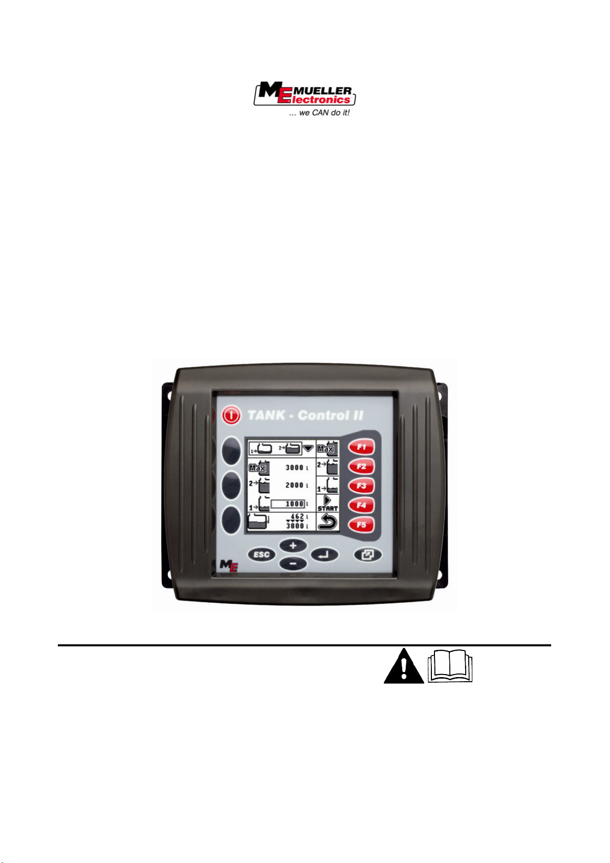
TANK-Control II
Version: V1.20130320
30252060-02-EN Read and follow these operating instructions.
Keep these operating instructions in a safe place for later
reference.
Page 2

Document
Copyright ©
Imprint
Installation and Operating Instructions
Product: TANK-Control II
Document number: 30252060-02-EN
From software version: 6.4
Original language: German
Müller-Elektronik GmbH & Co.KG
Franz-Kleine-Straße 18
33154 Salzkotten
Germany
Phone: ++49 (0) 5258 / 9834 - 0
Fax: ++49 (0) 5258 / 9834 - 90
Email: [email protected]
Homepage: http://www.mueller-elektronik.de
Page 3
Copyright © Müller-Elektronik GmbH & Co.KG
3
1
For your safety
5
1.1
Basic safety instructions
5
1.2
Intended use
5
1.3
Layout and meaning of warnings
5
1.4
Alarm messages on the screen
6
1.5
Safety stickers on the product
7
1.6
EC declaration of conformity
7
1.7
Disposal
7
2
Product description
8
2.1
System overview
8
2.2
What can TANK-Control II do?
8
2.3
Understanding the information on the nameplate
9
3
About these Operating Instructions
10
3.1
Who should use the Operating Instructions?
10
3.2
Screen shots in these Operating Instructions
10
3.3
Layout of instructions
10
3.4
Layout of references
10
4
Installation instructions
12
4.1
Safety during installation
12
4.2
System requirements
12
4.3
Installing the sensor
12
4.3.1
Step 1: Drill holes into the tank
13
4.3.2
Step 2: Install the tube socket
14
4.3.3
Step 3: Prepare the sensor tube
15
4.3.4
Step 4: Install the sensor tube
16
4.4
Installing the control unit
17
5
Explanation of the control unit
18
5.1
Functions of the control area
18
5.2
Screen structure
19
6
Switching the control unit on and off
20
7
"Service" menu - entering basic settings
21
7.1
Opening the "Service" menu
21
7.2
Setting the language
21
7.3
Setting the system of measurement
22
7.4
Deactivating CAN communication
22
7.5
Setting the date and time
23
Contents
Contents
Page 4

4
Copyright © Müller-Elektronik GmbH & Co.KG
7.6
Setting the screen brightness and contrast
24
8
"Sensors" menu - configuration and calibration
25
8.1
Opening the "Sensors" menu
25
8.2
Carrying out 100 litre calibration
26
8.3
Carrying out basic initialisation
27
8.4
Entering the tank size
28
8.5
Carrying out calibration
29
8.5.1
Planning calibration
29
8.5.2
Carrying out automatic calibration
31
8.5.3
Entering calibration values manually
35
8.6
Setting the sensor sensitivity
36
9
"Tank Control II" menu - Filling and operation
38
9.1
Opening the "Tank Control II" menu
38
9.1.1
Opening the "Tank Control II" menu on the control unit
39
9.1.2
Opening the "Tank Control II" menu on the terminal in the tractor cab
39
9.2
Calculating the volume of spray required
40
9.3
Filling the tank
41
9.4
Displaying the workable area
44
9.5
Controlling external devices
44
9.5.1
Activating and deactivating external devices
44
9.5.2
Changing the mode of the external devices
46
9.5.3
Viewing the configuration of the external devices
47
9.5.4
Using a filling pump
48
9.5.5
Using a ball valve
49
9.5.6
Using an agitator
50
10
Using two sensors
53
10.1
Adding a second sensor
53
10.2
Configuring the second sensor
54
11
Configuring external devices
55
11.1
Configuring a filling pump
55
11.2
Configuring a ball valve
56
11.3
Configuring an agitator
57
12
Maintenance and technical data
59
12.1
Simulating the fill level
59
12.2
Managing system settings
59
12.3
Technical data
61
13
Appendix
63
Contents
Page 5
Copyright © Müller-Elektronik GmbH & Co.KG
5
WARNING
bodily injury if they are not avoided.
CAUTION
injury or damage to property if they are not avoided.
1
1.1
1.2
1.3
For your safety
Basic safety instructions
For your safety
1
Please read the following safety instructions carefully before operating the product for the first time.
▪ Please read these Installation and Operating Instructions carefully and follow all the safety
instructions.
▪ Keep children away from the control unit and sensor.
▪ Do not make any unauthorized modifications to the product. Unauthorized modifications or use
may impair safety and reduce the service life or operability of the unit. Modifications are
considered unauthorized if they are not described in the product documentation.
▪ Never remove any safety mechanisms or stickers from the product.
▪ Before performing any welding operations on the tractor or a trailed machine, always disconnect
the power supply to the terminal.
Intended use
TANK-Control II is intended exclusively for use in agriculture.
Intended use also means operating and maintaining the device in accordance with the manufacturer's
specifications.
The manufacturer shall not be held responsible for any installation or use that goes beyond this.
The manufacturer cannot be held liable for any personal injury or property damage resulting from
such improper use. All risks associated with improper usage must be borne entirely by the user. Any
Basic safety instructions
unauthorized modifications made to the equipment will void the manufacturer's warranty.
Layout and meaning of warnings
All safety instructions found in these Operating Instructions follow the pattern set out below:
This signal word identifies medium-risk hazards which could potentially cause death or serious
This signal word identifies low-risk hazards which could potentially cause minor or moderate bodily
Page 6
6
Copyright © Müller-Elektronik GmbH & Co.KG
NOTICE
This signal word identifies actions which could lead to operational malfunctions if performed
These actions require you to work in a precise and careful way in order to produce optimum results.
possible solution
Example
1.4
For your safety
1
Alarm messages on the screen
incorrectly.
Some actions need to be performed in several steps. If there is a risk involved in carrying out any of
these steps, a safety warning will appear in the instructions themselves.
Safety instructions always directly precede the step involving risk and can be identified by their bold
font type and a signal word.
1. NOTICE! This is a notice. It warns that there is a risk involved in the next step.
2. Step involving risk.
Alarm messages on the screen
While working with the field sprayer, an alarm message may appear on the screen.
The purpose of the alarm messages is as follows:
▪ Warning - They warn the operator if the current state of the field sprayer could lead to a
dangerous situation.
▪ Information - They inform the operator that the current state of the field sprayer or the
configuration has changed and may lead to faults during operation.
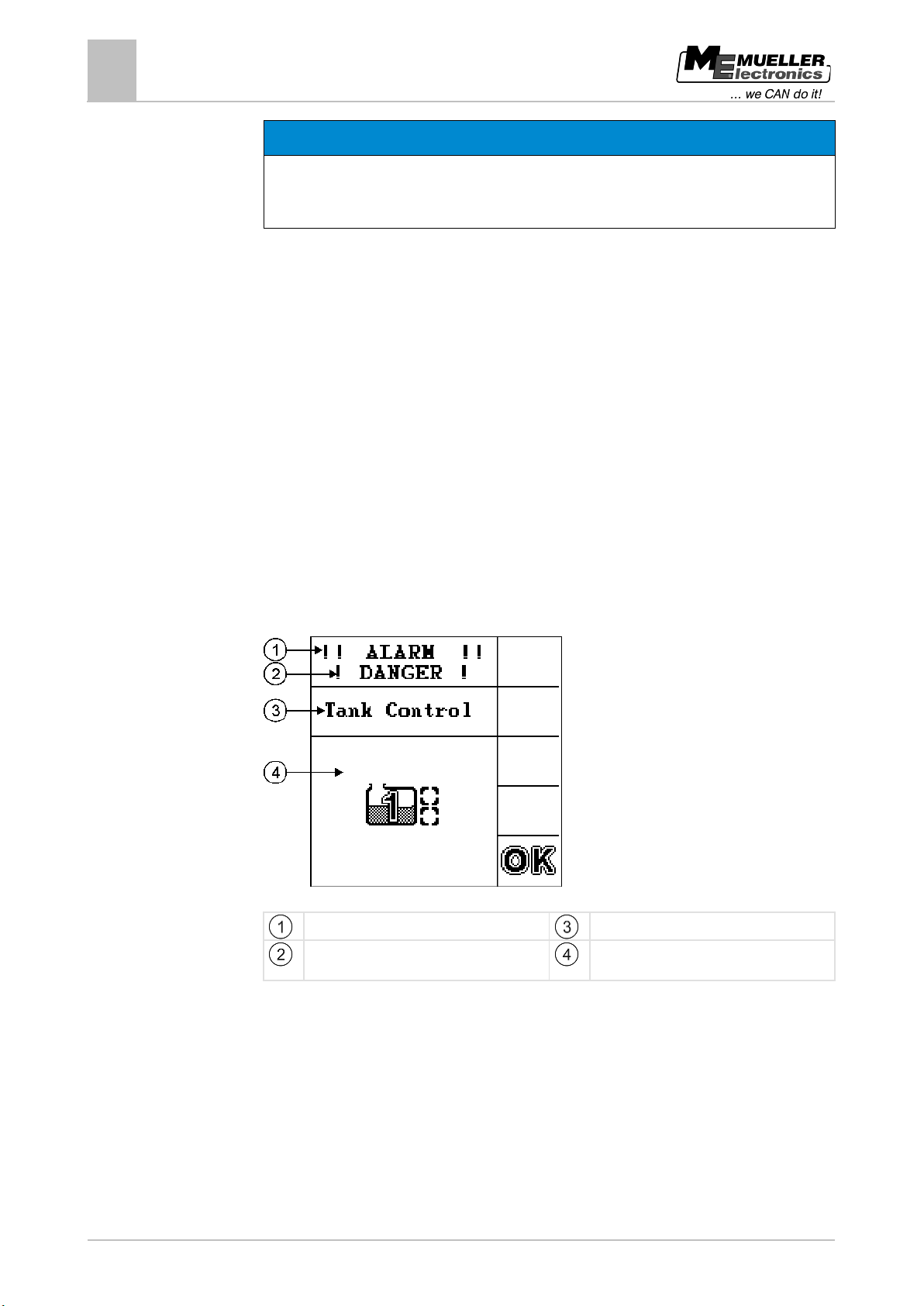
On the following screen shot, you can see how the alarm messages are structured:
Example of an alarm message
The word "ALARM" always appears
Type of alarm message
Name of the component that caused the alarm
Illustration or description of the problem and
Page 7
Copyright © Müller-Elektronik GmbH & Co.KG
7
1.5
1.6
1.7
For your safety
Safety stickers on the product
1
Safety stickers on the product
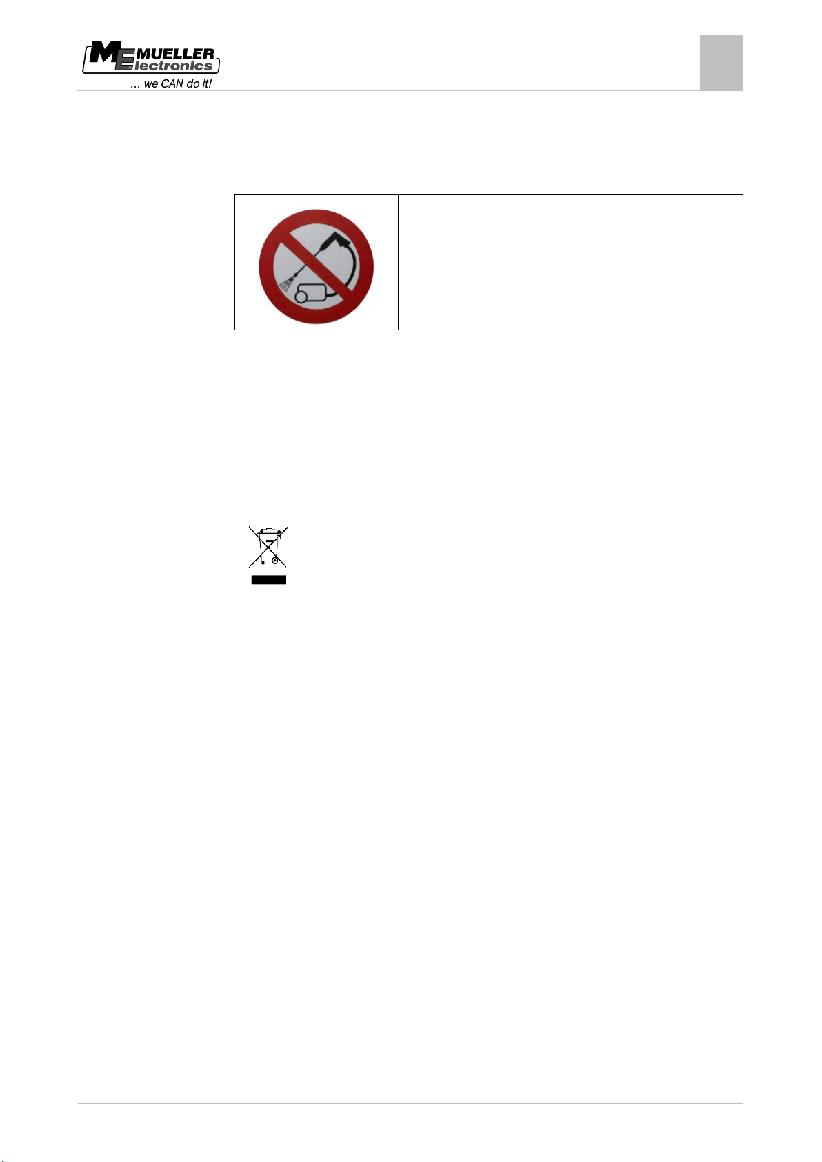
Sticker on the control unit
Do not clean with a high-pressure cleaner.
EC declaration of conformity
This product has been manufactured in conformity with the following national and harmonised
standards as specified in the current EMC Directive 2004/108/EC:
▪ EN ISO 14982
Disposal
When it has reached the end of its service life, please dispose of this product as
electronic scrap in accordance with all applicable waste management laws.
Page 8
8
Copyright © Müller-Elektronik GmbH & Co.KG
2
2.1
2.2
Product description
2
System overview
Product description
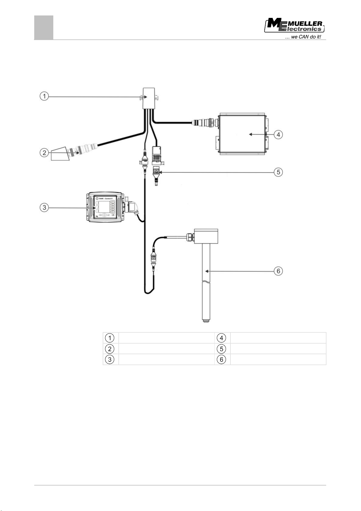
System overview
Sensor with TANK-Control II control unit
What can TANK-Control II do?
TANK-Control II is a system which consists of a computer and a sensor:
▪ The computer is an integral part of a control unit.
▪ The sensor measures the actual fill level in the tank.
Summary of TANK-Control II capabilities:
▪ Display the current fill level.
▪ Calculate the spray volume required.
▪ Calculate the workable area.
▪ TANK-Control II functions with a range of liquids.
▪ Data is displayed on the control unit and on the terminal in the tractor cab.
Cable harness
ISOBUS connector, tractor
TANK-Control II control unit
Job computer, sprayer
Termination plug
TANK-Control II sensor
Page 9
Copyright © Müller-Elektronik GmbH & Co.KG
9
number will be shown here.
longer be up-to-date.
2.3
Product description
Understanding the information on the nameplate
2
▪ TANK-Control II can control a number of components:
– Filling pumps and ball valves for filling,
– Agitators used during spraying work.
▪ You can also operate TANK-Control II with two sensors.
Understanding the information on the nameplate
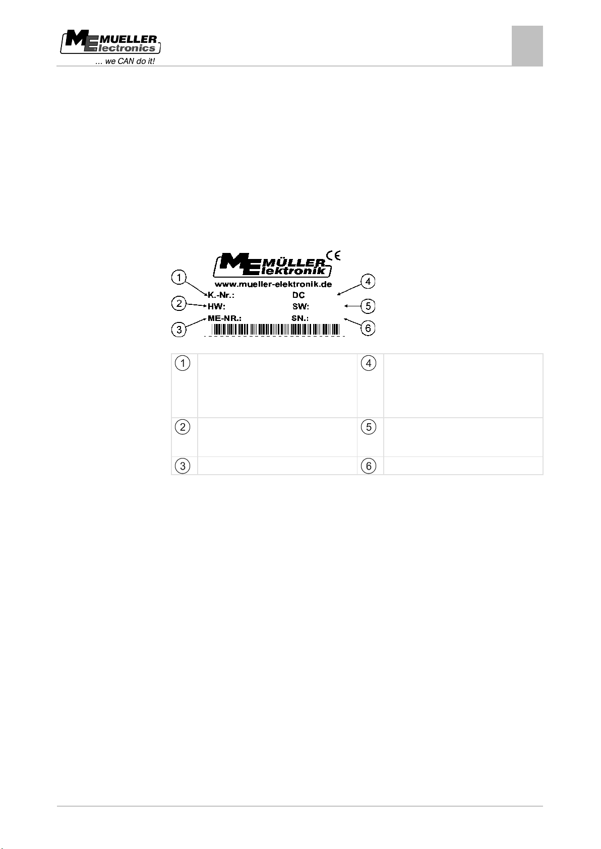
On the underside of the control unit you will find a nameplate sticker. On this sticker you can find all
the information you need to identify the product.
Have these details ready when you contact Customer Services.
Information on the nameplate
Client’s item number
If the product was manufactured for an
agricultural machinery manufacturer, the
agricultural machinery manufacturer's item
Hardware version
Operating voltage
The product may only be connected to
voltages within this range.
Software version at the time of delivery.
If you update the software, this version will no
Müller-Elektronik item number
Serial number
Page 10
10
Copyright © Müller-Elektronik GmbH & Co.KG
Type of symbol
Meaning
2.
⇨
This will happen when you perform an action.
⇨
the steps.
before an action can be performed.
3
3.1
3.2
3.3
3.4
About these Operating Instructions
3
Who should use the Operating Instructions?
About these Operating Instructions
Who should use the Operating Instructions?
These Operating Instructions are intended for:
▪ People who use the field sprayer.
▪ People who install the sensor.
▪ People who install and use the control unit.
Screen shots in these Operating Instructions
The screen shots of the software interface are presented for reference purposes. They help you to
find your way around the software screens.
The information shown on the screen is dependent on various factors:
▪ the type of field sprayer,
▪ the configuration,
▪ the status.
For this reason the information shown on the screen shots in these Operating Instructions may be
different from that displayed on the terminal.
Layout of instructions
The instructions explain step by step how to perform certain operations with the product.
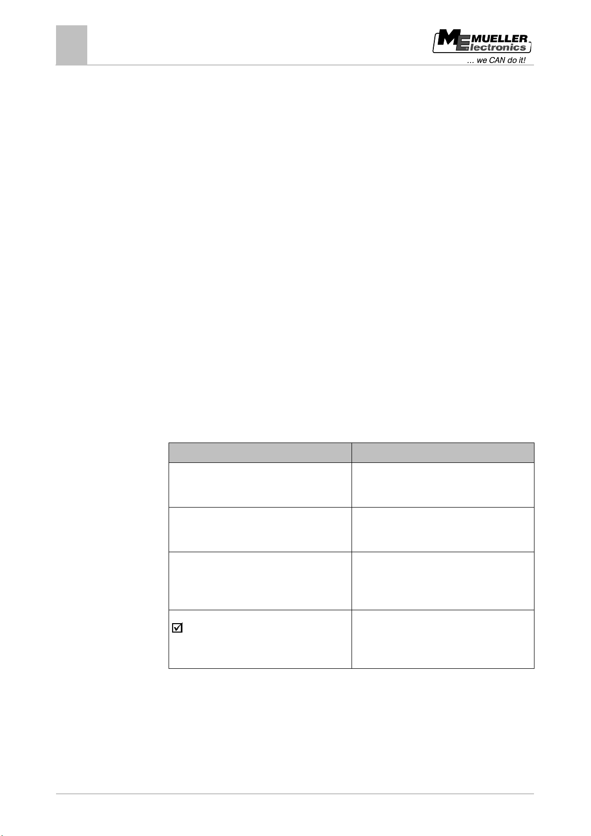
Throughout these Operating Instructions we use the following symbols to identify instructions:
1.
Actions that must be performed in succession.
Result of the action.
Result of an instruction.
This will happen when you have completed all
Requirements.
Any requirements specified must be put in place
Layout of references
If any references are given in these Operating Instructions, they will appear as follows:
Example of a reference: [➙ 10]
Page 11
Copyright © Müller-Elektronik GmbH & Co.KG
11
About these Operating Instructions
Layout of references
3
References can be identified by square brackets and an arrow. The number following the arrow
shows you the page where the chapter starts and where you can find further information.
Page 12
12
Copyright © Müller-Elektronik GmbH & Co.KG
Number
Part
Number
Part
1
Float
8
Washer A8.4 (large)
1
Flange 140
4
Washer A8.4
1
Viton gasket 140
1
Tube socket
4
Viton gasket 25x8x3
2
Viton gasket 25x6
4
Hexagonal screw M8x35
1
Nut M6 (self-locking)
4
Nut M8
1
Washer 24.2x12.2
4
Nut M8 flat
1
Washer A6.4
8
Spring washer B8
1
Locking ring
4
4.1
4.2
4.3
Installation instructions
4
Safety during installation
Installation instructions
Safety during installation
This chapter is intended for specialists and agricultural machinery manufacturers who install the
sensor and control unit.
▪ Please read these installation instructions carefully and follow all the instructions.
▪ Do not install the product unless you know how to install it on agricultural machines.
▪ Only install the sensor when the tank is new.
▪ Take safety measures to ensure that you do not fall if you climb onto the tank while installing the
sensor.
▪ If you climb into the tank, ensure that a second person is watching you and can help you in an
emergency.
System requirements
Software version 6.4 at least must be installed on the job computer for the field sprayer.
Installing the sensor
To install the sensor, you will need carry out the following steps independently of one another:
Step 1: Drill holes into the tank
Step 2: Install the tube socket
Step 3: Prepare the sensor tube
Step 4: Install the sensor tube
Before installation
Check that you have all the parts:
Page 13
Copyright © Müller-Elektronik GmbH & Co.KG
13
4.3.1
Procedure
Installation instructions
Installing the sensor
4
Step 1: Drill holes into the tank
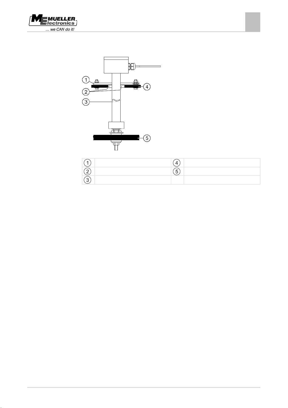
Drill holes into the tank
Flange 140
Top of tank
Opening
Base of tank
Sensor tube
The field sprayer must be standing on level ground.
1. Drill a hole (55 mm diameter) in the top of the tank for the sensor tube opening.
2. Mark the drilling positions. To do this, push the sensor tube and flange through the hole. Using
the flange 140 as a drilling template, mark the screw positions on the tank.
3. Drill 4 holes (8.5 mm diameter) at the positions marked; they will be used to attach the flange.
4. Pull the sensor tube out of the tank.
5. Use a plumb-line to identify a point directly below the hole on the base of the tank.
6. Mark the position for the hole.
7. Drill a hole (6.2 mm diameter) at the point you have marked so that you can install the tube
socket.
8. You can now install the tube socket.
Page 14
14
Copyright © Müller-Elektronik GmbH & Co.KG
4.3.2
Procedure
Installation instructions
4
Installing the sensor
Step 2: Install the tube socket
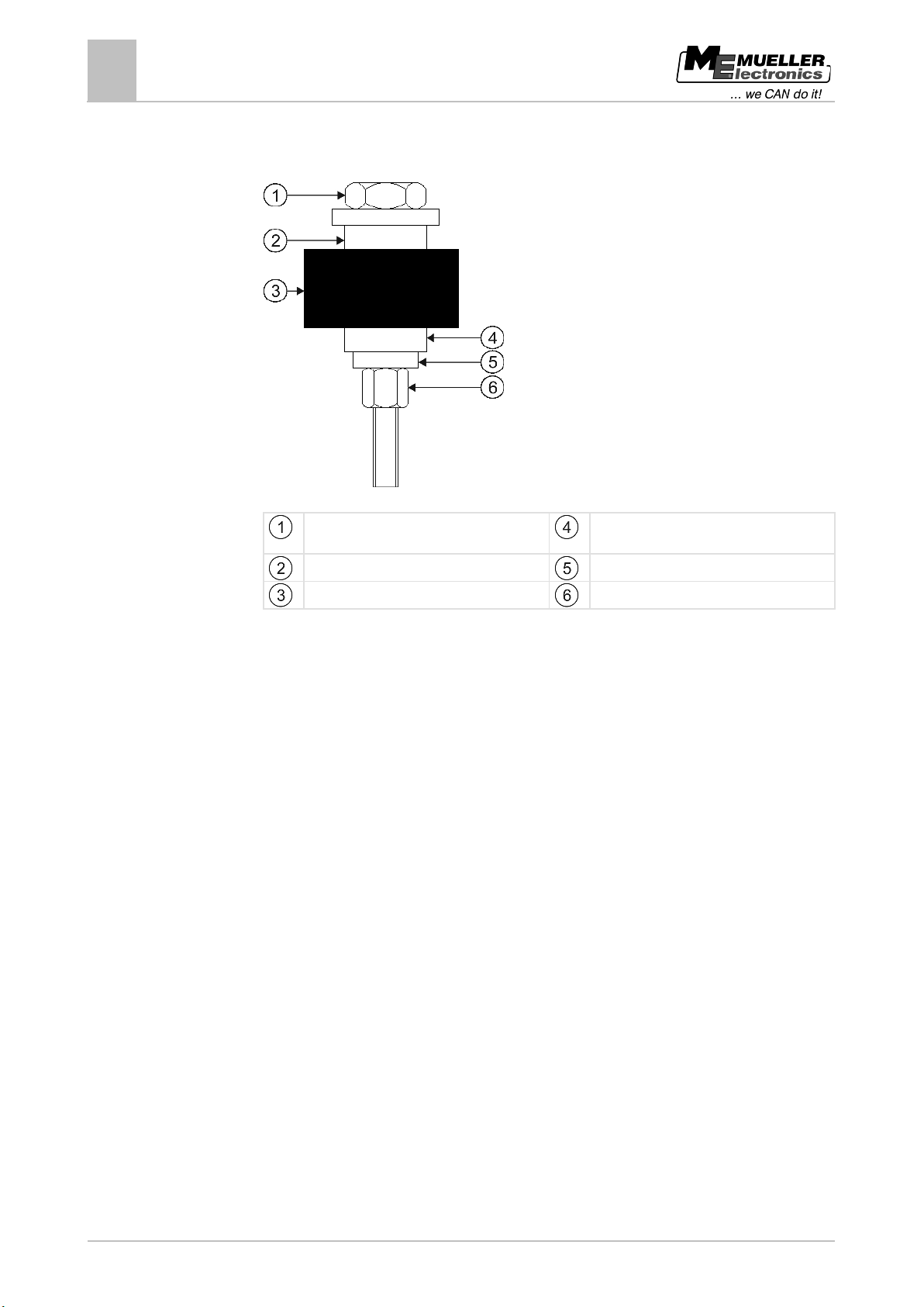
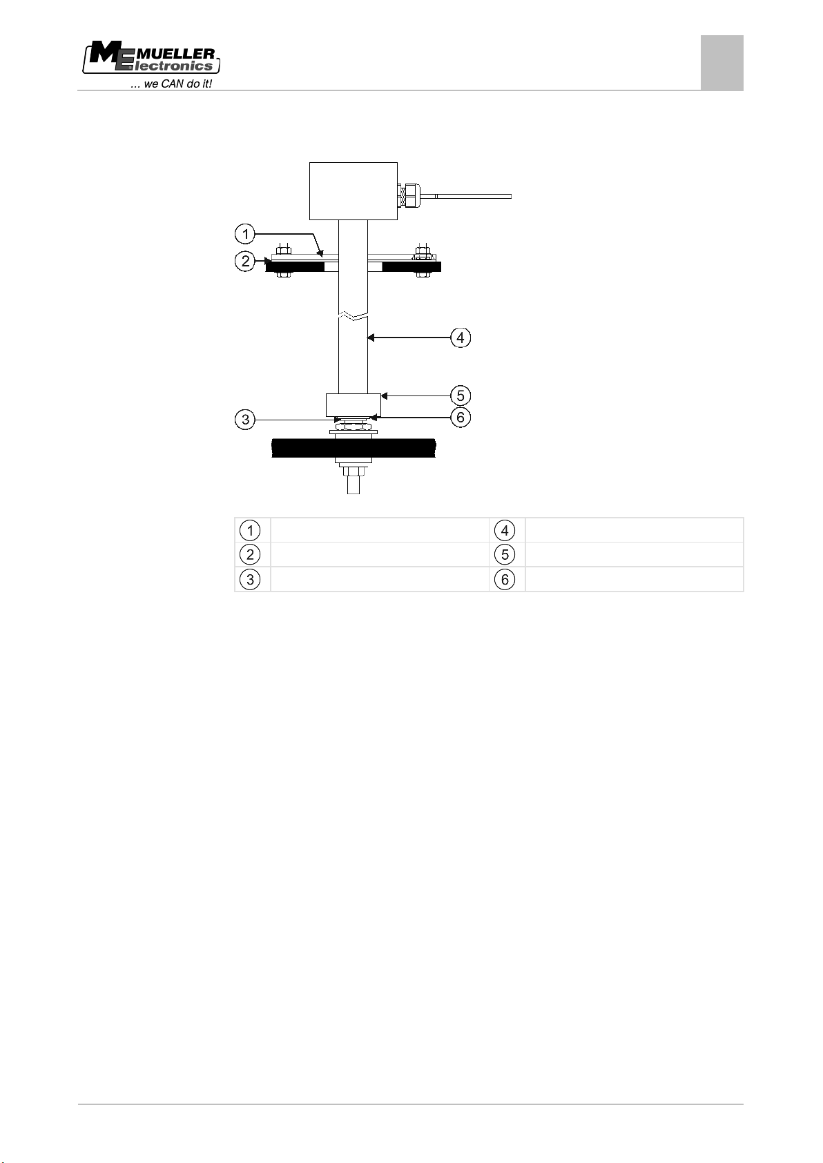
Install the tube socket
Tube socket
Viton gasket 25x6
Viton gasket 25x6
Base of tank
Washer 24.2x12.2
Nut M6
1. Push a Viton gasket 25x6 onto the tube socket.
2. Push the tube socket through the hole in the tank base from above.
3. Push the second Viton gasket 25x6 onto the tube socket from below.
4. Push the washer 24.2x12.2 onto the tube socket.
5. Fix the tube socket in place using nut M6.
6. You can now prepare the sensor tube.
Page 15
Copyright © Müller-Elektronik GmbH & Co.KG
15
Locking ring
Washer A6.4
4.3.3
Procedure
Installation instructions
Installing the sensor
4
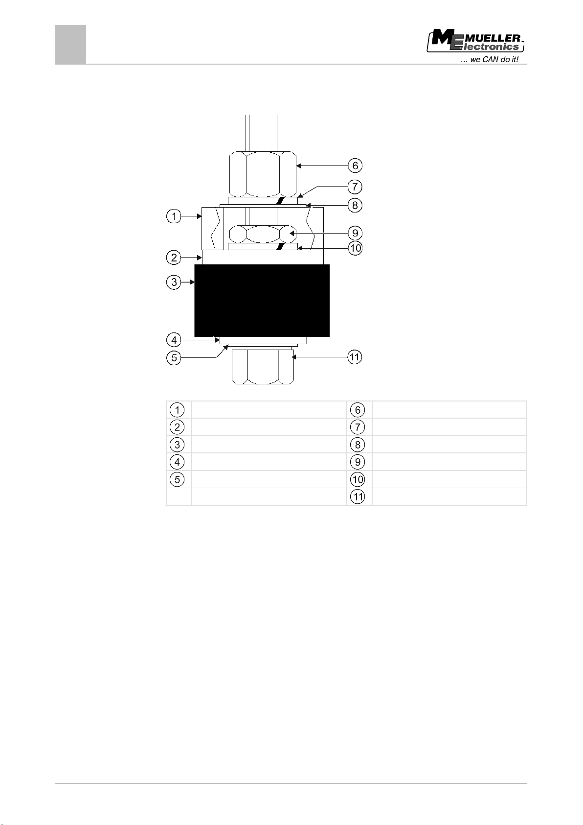
Step 3: Prepare the sensor tube
Prepare the sensor tube
Flange 140
Viton gasket 140
Sensor tube
Float
1. Push the flange 140 onto the sensor tube from below.
2. Push the Viton gasket 140 onto the sensor tube from below.
3. Push the float onto the sensor tube. The "0" marking on the float must point upwards.
4. Push washer A6.4 onto the sensor tube.
5. Secure washer A6.4 using the locking ring.
6. Carefully loosen the locking ring so that you can turn it over the thread.
7. You can now install the sensor tube.
Page 16
16
Copyright © Müller-Elektronik GmbH & Co.KG
Flange 140
Nut M8
Washer A8.4, large
Spring washer B8
4.3.4
Procedure
Installation instructions
4
Installing the sensor
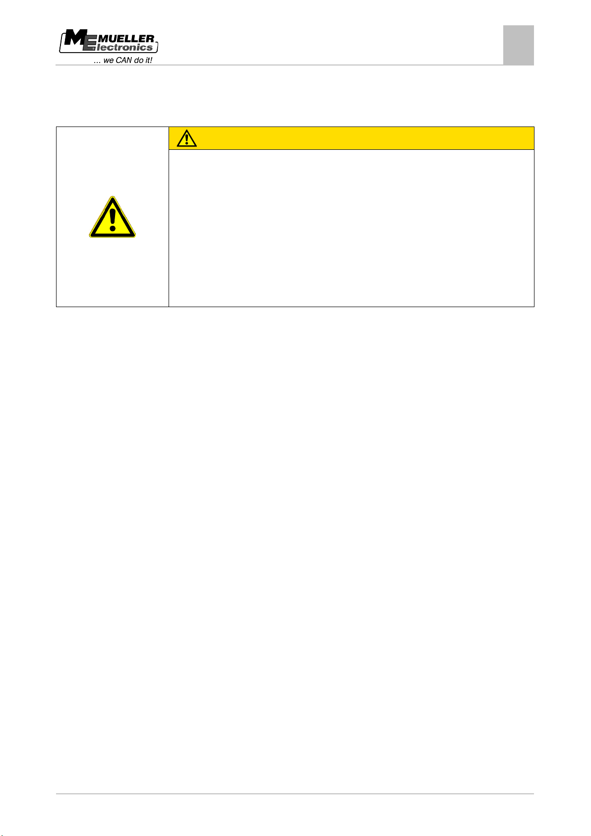
Step 4: Install the sensor tube
Install the sensor tube
Viton gasket 140
Top of tank
Viton gasket 25x8x3
Spring washer B8
Washer A8.4
Nut M8 flat
Hexagonal screw M8
1. Push the prepared sensor tube through the opening at the top of the tank.
2. Screw the sensor tube into the tube socket on the tank base.
3. Push a washer A8.4 (large) and a Viton gasket 25x8x3 onto each of the 4 hexagonal screws M8.
4. Push the screws upwards through the tank cover.
5. Push a spring washer B8 onto the screws from above.
6. Secure the screws using the nuts M8 flat.
7. Push the Viton gasket 140 and the flange downwards.
8. Push a washer A8.4 and a spring washer B8 onto the screws.
9. Secure the screws using the nuts M8.
10. You have completed the installation.
Page 17
Copyright © Müller-Elektronik GmbH & Co.KG
17
CAUTION
Damage if a corrugated pipe is not installed correctly
◦ Remove all kinks and folds from a corrugated pipe before connecting it.
4.4
Installation instructions
Installing the control unit
4
Installing the control unit
If you use a corrugated pipe and secure it incorrectly, it may deform or kink.
Vibration may then cause chafing on internal lines.
When installing a corrugated pipe:
◦ Ensure that the corrugated pipe does not kink during installation.
◦ Ensure that the corrugated pipe does not deform if secured with cable ties.
◦ Do not attach the corrugated pipe to hydraulic lines.
◦ Ensure that the corrugated pipe is fixed to solid, non-vibrating parts.
When installing the control unit you must:
▪ Use the mount provided as a template for the holes.
▪ Install the control unit so that the name "TANK-Control II" is horizontal and legible.
▪ Leave enough room for the cables.
▪ Wire the control unit to the sensor, the job computer for the field sprayer and the terminal in the
tractor cab. [➙ 8]
Page 18
18
Copyright © Müller-Elektronik GmbH & Co.KG
CAUTION
Danger if controls are pressed without care
property.
Switch control unit on and off.
screen.
Increase input values or move cursor up.
Open the start screen.
screen or cancel input.
Reduce input values or move cursor down.
5
5.1
Explanation of the control unit
5
Functions of the control area
Explanation of the control unit
The control unit consists of two parts:
▪ Control area with keys. This is where you control the device.
▪ Monitor on which various screens and functions are displayed.
Functions of the control area
When you press the keys or function keys on the control unit, parts of the machine connected to the
unit may move or be activated.
As a result, people can be injured or property damaged.
Before pressing the keys or function keys:
◦ Take all the steps described in the machine's Operating Instructions in order to avoid danger.
◦ Only press the keys or function keys when you are sure that there is no danger to people or
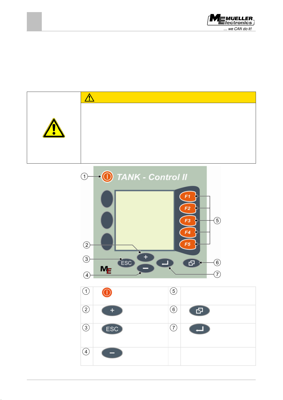
Keys on the control unit
Key
Function keys
Activate functions that are displayed on the
Key
Key
Leave current screen and open previous
Key
Key
Key
Confirm.
Page 19
Copyright © Müller-Elektronik GmbH & Co.KG
19
viewing.
you press the adjacent function key.
5.2
Explanation of the control unit
Screen structure
5
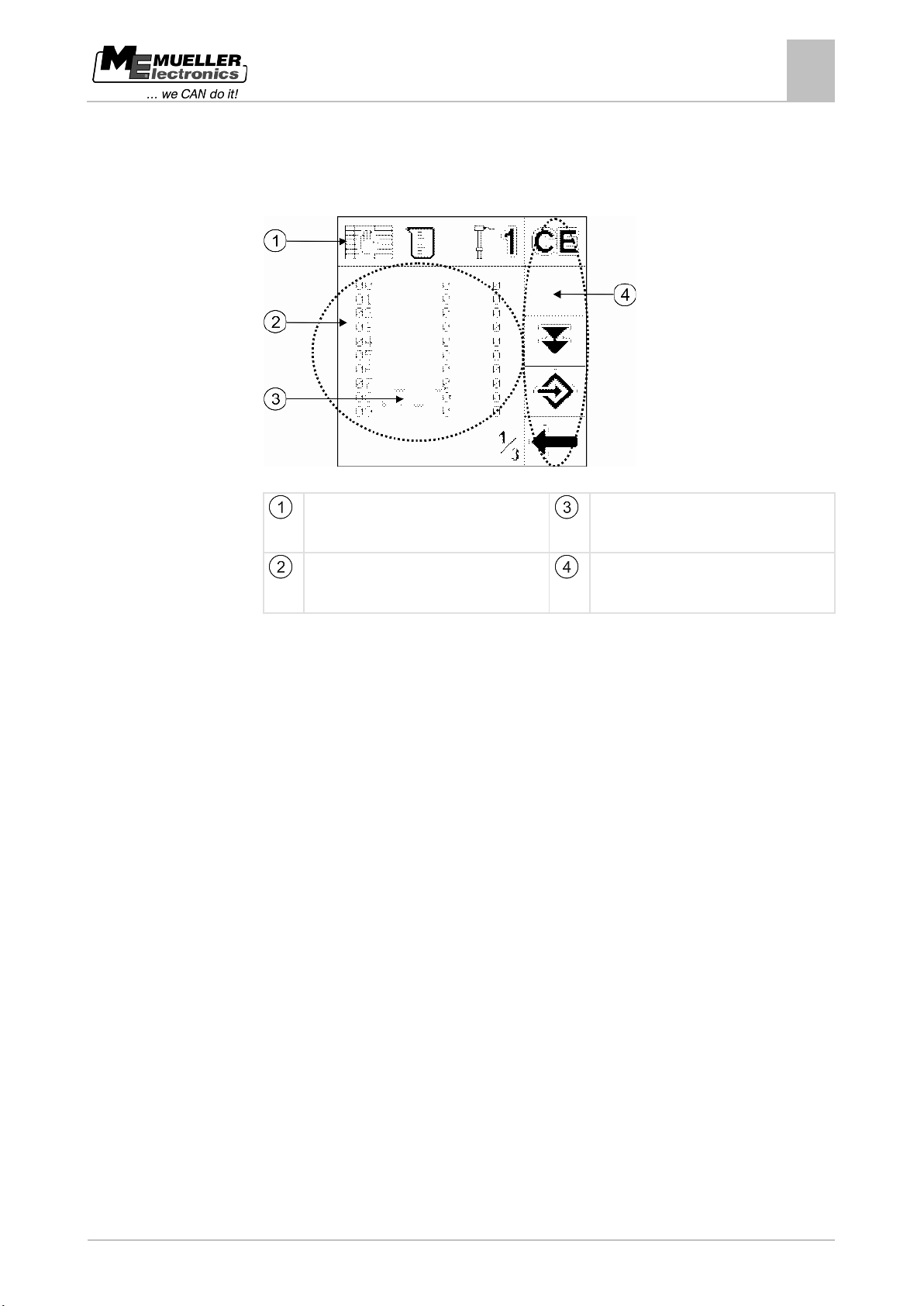
Screen structure
"Screen" means everything shown on the screen.
Elements of a screen
Screen icon
This icon shows which screen you are
Cursor
Shows which field you have selected.
Main area
Content of the screen displayed.
Function icons
Indicate which function you can carry out if
Page 20
20
Copyright © Müller-Elektronik GmbH & Co.KG
6
Procedure
Switching the control unit on and off
6
Switching the control unit on and off
Switching the control unit on
The control unit is switched on together with the terminal and the job computer for the field sprayer.
1. Switch on the terminal in the tractor cab; the control unit also starts automatically.
2. Wait approx. 15 seconds for all the functions to load.
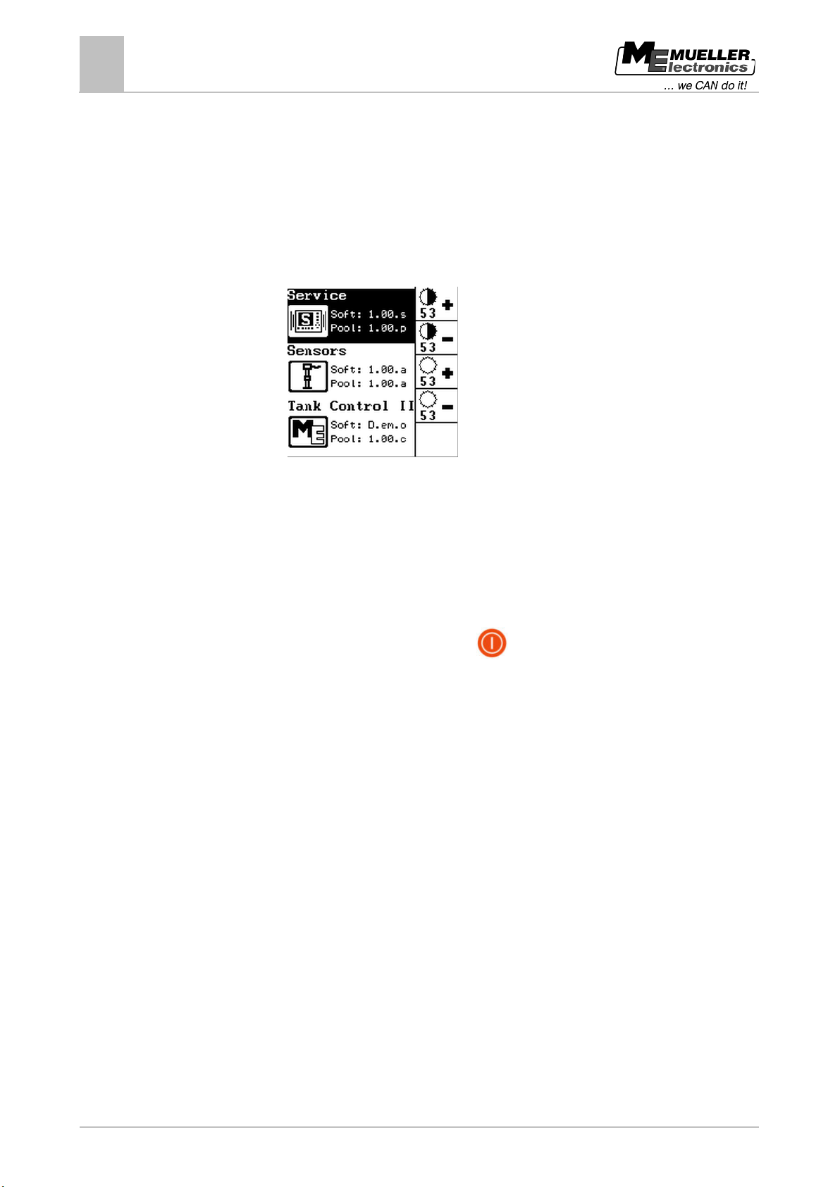
⇨ The following screen appears on the control unit:
⇨ The start screen displays three menus: "Service", "Sensors" and "Tank Control II". These
menus are all described in the next chapters.
Switching the control unit off
There are two ways of switching the control unit off:
1. By switching off the terminal in the vehicle cab.
⇨ The TANK-Control II control unit automatically switches off.
2. By switching off the control unit using the
key.
⇨ Only TANK-Control II is switched off. The terminal remains switched on.
Page 21
Copyright © Müller-Elektronik GmbH & Co.KG
21
7
7.1
Procedure
7.2
Procedure
"Service" menu - entering basic settings
Opening the "Service" menu
7
"Service" menu - entering basic settings
In the "Service" menu you can enter the following basic settings:
▪ Set the language
▪ Set the units
▪ Activate and deactivate CAN communication
▪ Set the date and time
▪ Display the voltage
On the start screen you can also set the screen brightness and contrast.
Opening the "Service" menu
To open the "Service" menu:
1. Start the control unit.
⇨ The start screen appears.
2. Select the "Service" line.
3. Press this key:
⇨ The following screen will appear:
⇨ You can now enter the basic settings.
Setting the language
You can choose from the following languages:
▪ German
▪ English
▪ French
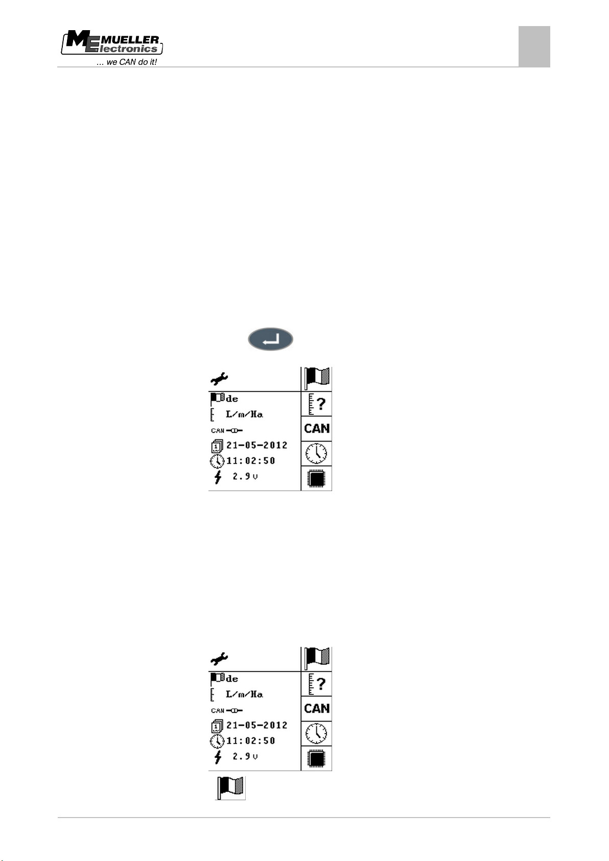
1. Open the "Service" menu.
⇨ The following screen will appear:
2. Press
until the required language is set.
Page 22
22
Copyright © Müller-Elektronik GmbH & Co.KG
7.3
Procedure
7.4
Procedure
"Service" menu - entering basic settings
7
Setting the system of measurement
⇨ The abbreviation for the language selected changes on the screen.
3. Restart the control unit.
Setting the system of measurement
You can choose one of the following systems of measurement:
▪ Metric: L/m/Ha
▪ Imperial: Gal/y/A (UK)
▪ American: Gal/y/A (US)
1. Open the "Service" menu.
⇨ The following screen will appear:
2. Press
until the required system of measurement is set.
⇨ The system of measurement on the screen changes.
3. Restart the control unit.
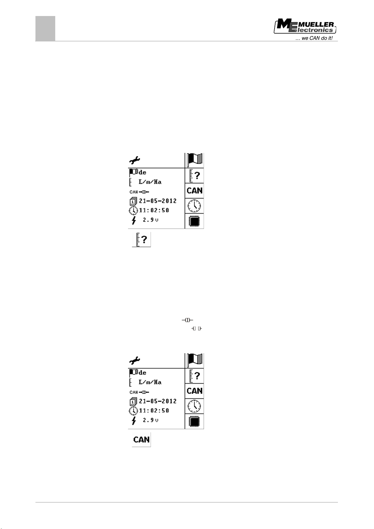
Deactivating CAN communication
You can disconnect or activate communication between TANK-Control II and the job computer for the
field sprayer:
▪ Communication is activated
▪ Communication is disconnected
1. Open the "Service" menu.
⇨ The following screen will appear:
2. Press
to disconnect or activate communication
⇨ The CAN communication icon on the screen changes.
3. Restart the control unit.
Page 23
Copyright © Müller-Elektronik GmbH & Co.KG
23
7.5
Procedure
"Service" menu - entering basic settings
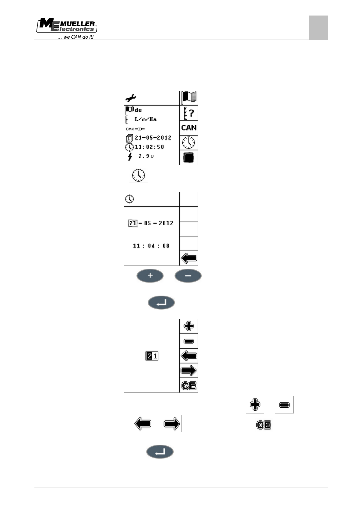
Setting the date and time
7
Setting the date and time
1. Open the "Service" menu.
⇨ The following screen will appear:
2. Press:
⇨ The following screen will appear:
3. Press the
and keys to select the position required.
⇨ The position selected is highlighted, in this case: the date 21.
4. Press this key:
⇨ The following screen will appear:
5. Enter the settings required. You have the following options:
number,
and to change the digit position, and to set all the values to
0.
and to change the
6. Press this key:
7. Repeat steps 3 to 6 for all the values you want to change.
Page 24
24
Copyright © Müller-Elektronik GmbH & Co.KG
Function icon
Meaning
7.6
Procedure
"Service" menu - entering basic settings
7
Setting the screen brightness and contrast
⇨ You have set the date and time.
Setting the screen brightness and contrast
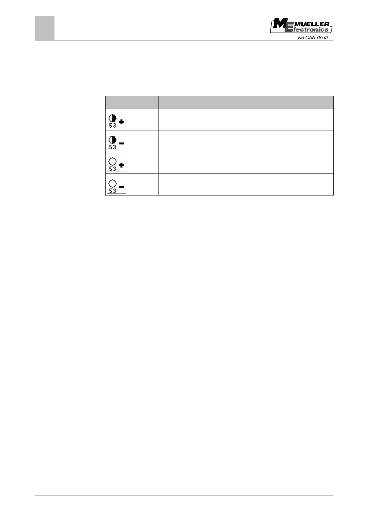
You can adjust the contrast and brightness of the display. You have the following options:
Increase contrast
Reduce contrast
Increase brightness
Reduce brightness
1. Start the control unit.
⇨ The start screen appears.
2. Use the function keys to enter the screen settings.
Page 25
Copyright © Müller-Elektronik GmbH & Co.KG
25
Configuration
Purpose
Who does it?
When?
tolerances
startup.
sensor
the sensor.
calibration
sprayer.
sensitive.
NOTICE
During calibration the tank must be filled manually. TANK-Control II cannot control filling pumps, ball
valves, etc. during calibration.
8
8.1
Procedure
"Sensors" menu - configuration and calibration
Opening the "Sensors" menu
8
"Sensors" menu - configuration and calibration
You must configure and calibrate the sensor before you use TANK-Control II for the first time.
Who configures what?
100 litre calibration Equalise installation
Basic initialisation Recognise the
Tank size Prepare tank for
Calibration Determine sensor
values
User Prior to initial
Installer After installation of
Field sprayer manufacturer Before calibration.
Field sprayer manufacturer After the first
sensor has been
installed on a new
model of field
Sensor sensitivity Set the sensitivity of
the sensor
User If the sensor
response to water
movement is too
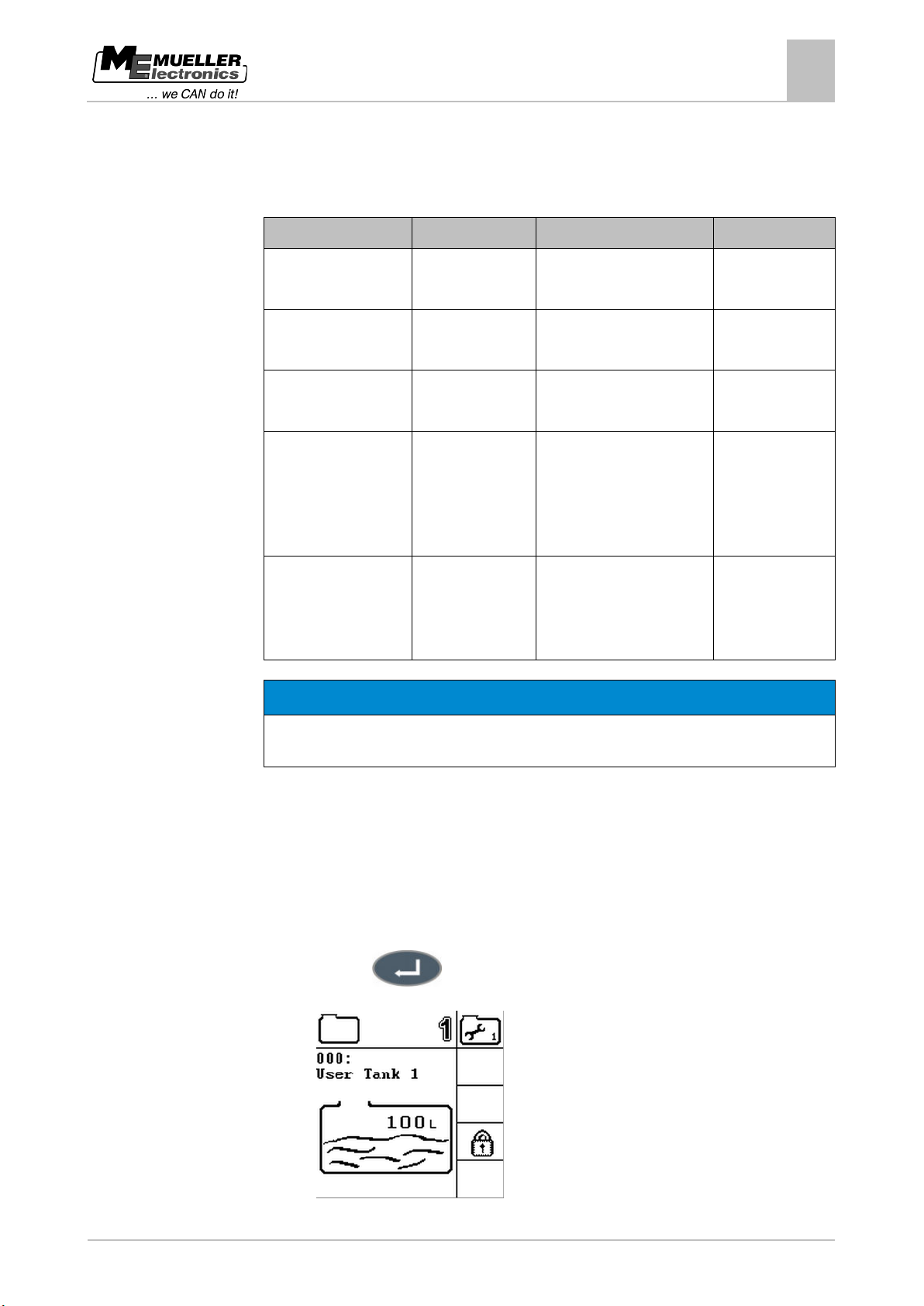
Opening the "Sensors" menu
To open the "Sensors" menu:
1. Start the control unit.
⇨ The start screen appears.
2. Select the "Sensors" line.
3. Press this key:
⇨ The following screen will appear:
Page 26
26
Copyright © Müller-Elektronik GmbH & Co.KG
WARNING
◦ Always use clean water.
NOTICE
◦ Use a flow meter or a weighbridge.
8.2
Procedure
"Sensors" menu - configuration and calibration
8
Carrying out 100 litre calibration
⇨ From this screen you can access all the other screens you need to configure the sensor.
Carrying out 100 litre calibration
Danger of poisoning from spray liquid residues
When configuring the tank:
Inaccurate calibration due to incorrect fill volume
If the configuration is wrong the fill level cannot be measured accurately. This makes all calculations
imprecise.
When calibrating the tank:
The purpose of the 100 litre calibration is:
▪ To equalise manufacturing tolerances
▪ To correct changes in accuracy over time.
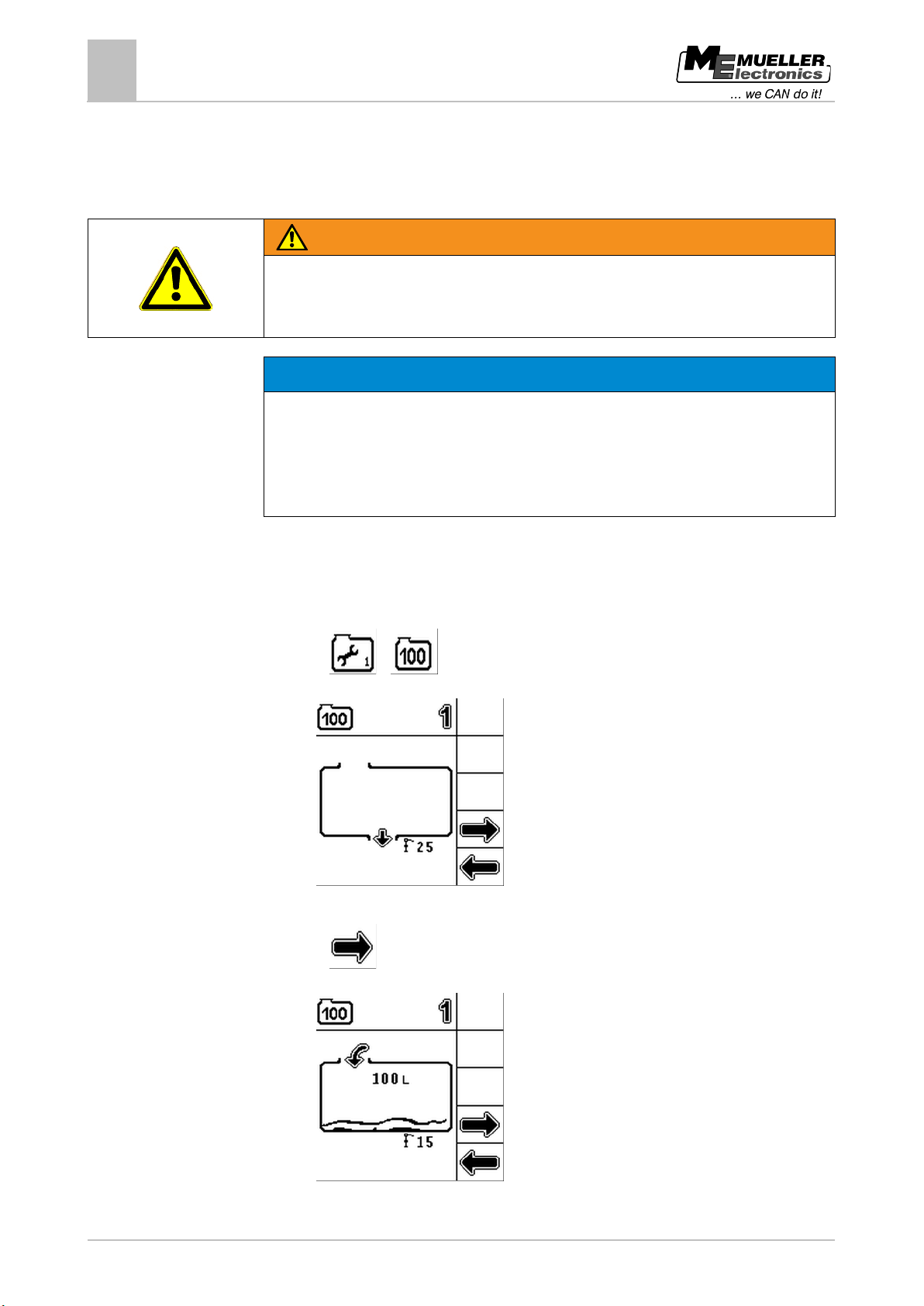
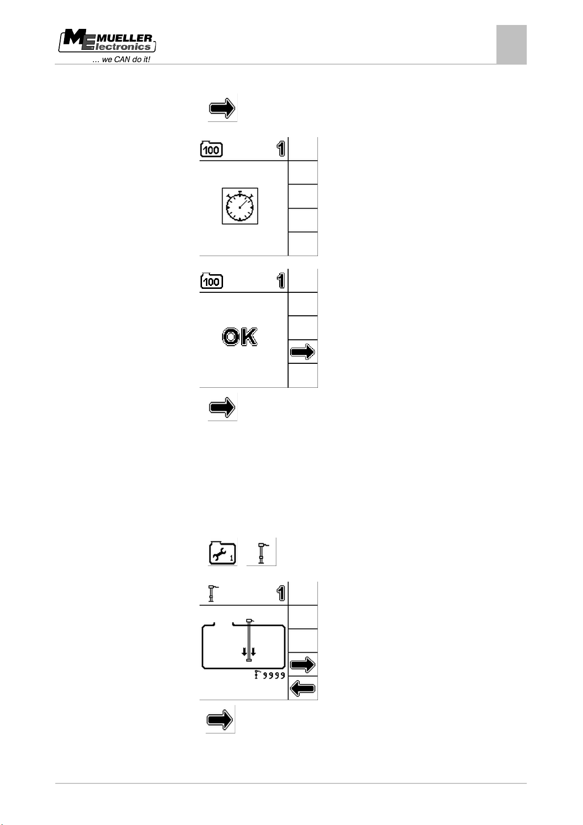
1. Open the "Sensors" menu.
2. Press:
>
⇨ The following screen will appear:
3. Empty the tank completely.
4. Press:
⇨ The following screen will appear:
5. Add exactly 100 litres of water to the tank.
Page 27
Copyright © Müller-Elektronik GmbH & Co.KG
27
8.3
Procedure
"Sensors" menu - configuration and calibration
Carrying out basic initialisation
8
6. Wait a short time until the water has settled.
7. Press:
⇨ The following screens appear one after the other:
8. Press:
⇨ You have successfully completed the 100 litre calibration.
Carrying out basic initialisation
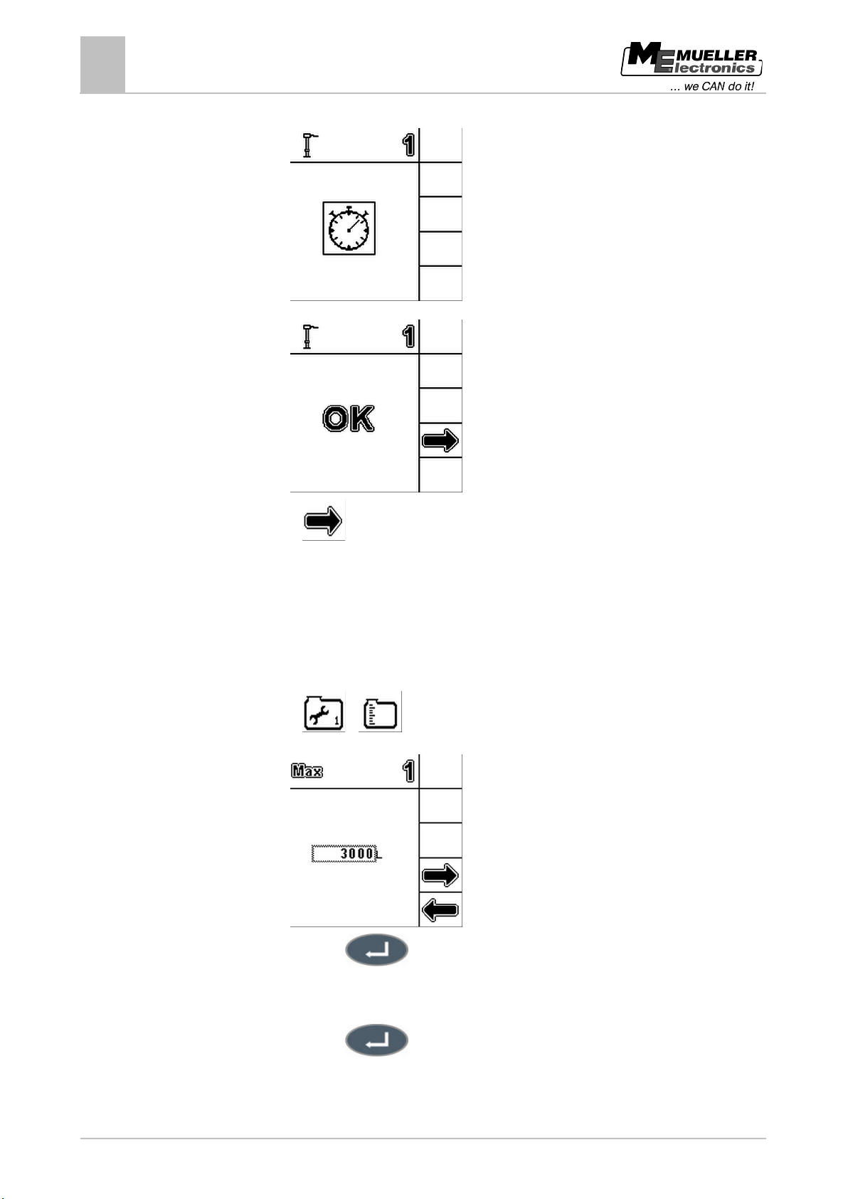
During basic initialisation the TANK-Control II control unit uses a signal to activate the sensor once in
order to ensure that all the connections are OK.
1. Open the "Sensors" menu.
2. Press:
>
⇨ The following screen will appear:
3. Press
to start basic initialisation.
Page 28
28
Copyright © Müller-Elektronik GmbH & Co.KG
8.4
Procedure
"Sensors" menu - configuration and calibration
8
Entering the tank size
⇨ The following screens appear one after the other:
4. Press:
⇨ You have initialised the sensor.
Entering the tank size
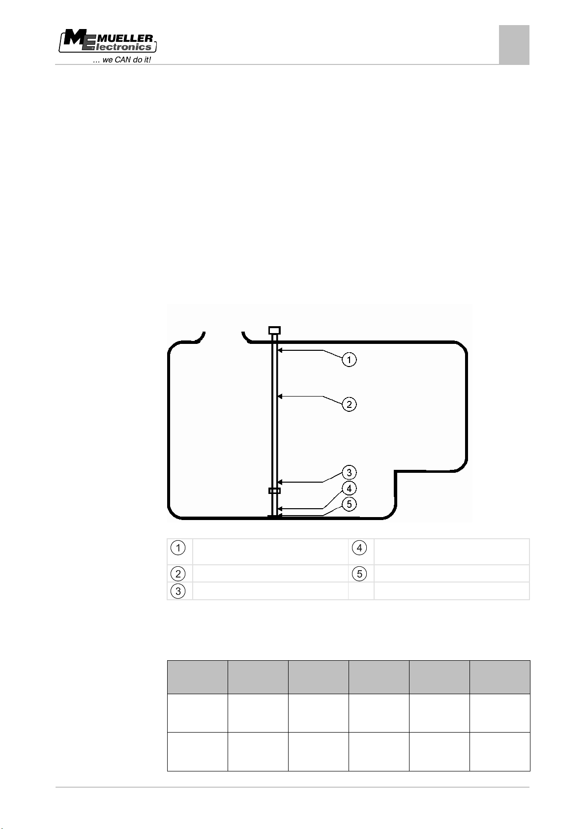
Before calibration you must enter the tank size.
1. Open the "Sensors" menu.
2. Press:
>
⇨ The following screen will appear:
3. Press this key:
⇨ The data input screen appears.
4. Enter the tank size in litres.
5. Press this key:
⇨ You have set the tank size.
Page 29
Copyright © Müller-Elektronik GmbH & Co.KG
29
Calibration point 29
Calibration
point
Float height
Possible fill
level
Calibration
point
Float height
Possible fill
level
be empty)
movement is
8.5
8.5.1
"Sensors" menu - configuration and calibration
Carrying out calibration
8
Carrying out calibration
The calibration process measures the height of the sensor float. The float height rises as the fill level
increases.
During calibration, the tank is filled with water in several steps. The exact position of the float is
measured at each step. The computer then knows the position of the float at every fill level.
These values are stored in the memory.
The following types of calibration are available:
▪ Automatic calibration.
▪ Manual input.
Planning calibration
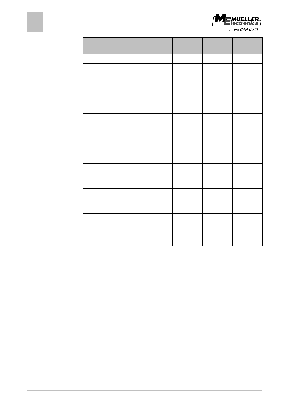
Before you start calibration, you must plan the float heights at which you want to enter the fill level.
Possible tank shape with calibration points
Maximum fill level
e.g.: Calibration point 21
Calibration point 02
Calibration point 01
Calibration point 00
The table below shows an example of what a planned calibration may look like. The values may be
different for every tank. You cannot plan the fill levels at given float heights. The fill levels depend on
the size and shape of the tank. In the example, the tank has a capacity of 7200 litres.
00 15mm 0 l (tank must
01 25mm 30 l (first float
15 750mm 3000 l
16 800mm 3200 l
Page 30
30
Copyright © Müller-Elektronik GmbH & Co.KG
point
level
Calibration
point
level
registered)
02
100mm
400 l
17
850mm
3400 l
03
15mm
600 l
18
900mm
3600 l
04
200mm
800 l
19
950mm
3800 l
05
250mm
1000 l
20
1000mm
4000 l
06
300mm
1200 l
21
1050 mm
4200 l
07
350mm
1400 l
22
1100mm
4400 l
08
400mm
1600 l
23
1200mm
4800 l
09
450mm
1800 l
24
1300mm
5200 l
10
500mm
2000 l
25
1400mm
5600 l
11
550mm
2200 l
26
1500mm
6000 l
12
600mm
2400 l
27
1600mm
6400 l
13
650mm
2600 l
28
1700mm
6800 l
reached)
"Sensors" menu - configuration and calibration
8
Carrying out calibration
Calibration
Float height Possible fill
Float height Possible fill
14 700mm 2800 l 29 1800mm 7200 l
(maximum fill
level is
This is how to plan the calibration:
1. Check whether your tank has any bulges as they can affect the float height.
2. Note that the tank must be completely empty at calibration point 00. You cannot select the float
height yourself.
3. Note that the fill level at which the float registers the first movement must be entered at
calibration point 01. You cannot select the float height yourself.
4. Note that the tank must be filled to the maximum fill level at the last calibration point. The
maximum fill level is specified by the tank manufacturer. You cannot select the float height
yourself.
5. Decide how many calibration points you want to use. You can use a maximum of 30 calibration
points.
6. Decide on the float heights at which you want to enter the fill level. If possible, use evenly spaced
intervals, e.g. every 50mm.
⇨ You can now start calibration.
Page 31
Copyright © Müller-Elektronik GmbH & Co.KG
31
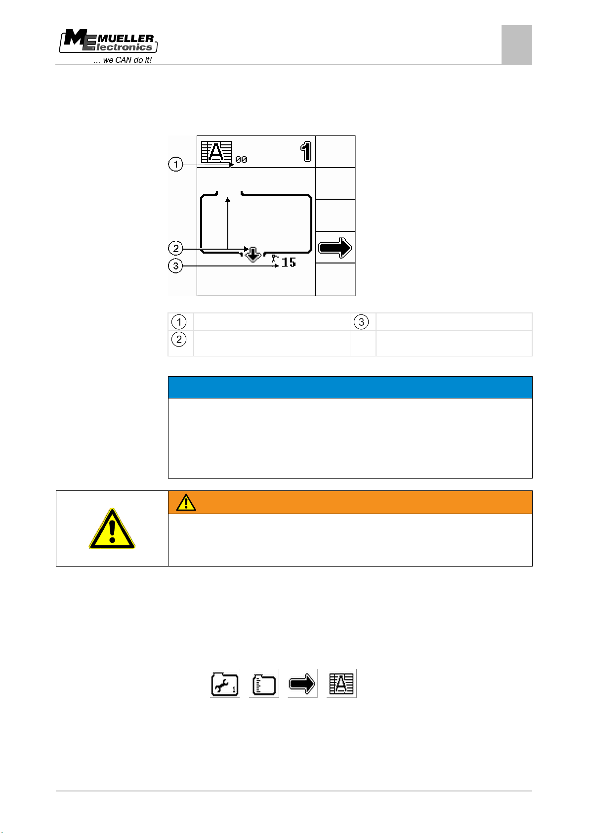
Current calibration point
Current float height in mm
drain
NOTICE
Inaccurate calibration due to incorrect fill volume
◦ Use a flow meter or a weighbridge.
WARNING
◦ Always use clean water.
8.5.2
Procedure
"Sensors" menu - configuration and calibration
Carrying out calibration
8
Carrying out automatic calibration
During automatic calibration you will often see the following screen:
Automatic Calibration screen
Next activity, either drain or fill, in this case:
If the configuration is wrong the fill level cannot be measured accurately. This makes all calculations
imprecise.
When calibrating the tank:
Danger of poisoning from spray liquid residues
When configuring the tank:
You have set the tank size.
You have completed the 100 litre calibration.
You have planned the float heights at which you want to enter the fill level.
You have pen and paper to hand to write down the fill levels.
1. Open the "Sensors" menu.
2. Press:
> > >
Page 32
32
Copyright © Müller-Elektronik GmbH & Co.KG
"Sensors" menu - configuration and calibration
8
Carrying out calibration
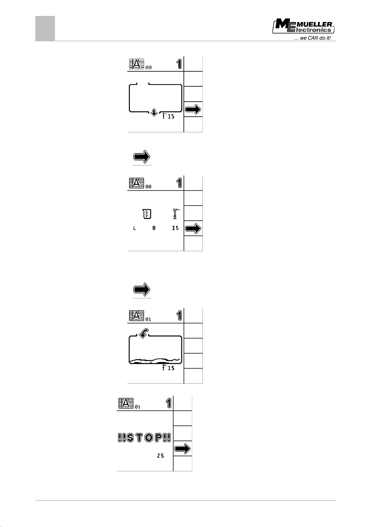
⇨ The following screen will appear:
3. Empty the tank completely.
4. Press:
⇨ The following screen will appear:
⇨ You have reached calibration point 00.
⇨ The fill level is exactly 0 litres.
⇨ The float height is 15mm.
5. Press:
⇨ The following screen will appear:
6. Fill the tank with water until the following screen appears:
7. Stop adding water.
Page 33
Copyright © Müller-Elektronik GmbH & Co.KG
33
"Sensors" menu - configuration and calibration
Carrying out calibration
8
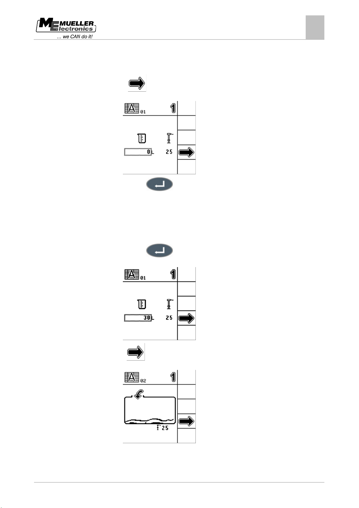
⇨ You have reached calibration point 01.
⇨ The sensor has registered the first movement.
⇨ The float height is 25mm.
8. Press:
⇨ The following screen will appear:
9. Press this key:
⇨ The data input screen appears.
10. Enter the current tank fill level. In the example, we assume a fill level of exactly 30 litres.
11. Write down the current fill level. You will then have a record of the values so you will not have to
repeat the entire calibration process if an error occurs, and can calibrate an identical tank
manually in the future.
12. Press this key:
⇨ The following screen will appear:
13. Press
to continue with calibration point 02.
⇨ The following screen will appear:
14. Fill the tank to the next planned float height. The planned level in the example is 100mm.
Page 34
34
Copyright © Müller-Elektronik GmbH & Co.KG
"Sensors" menu - configuration and calibration
8
Carrying out calibration
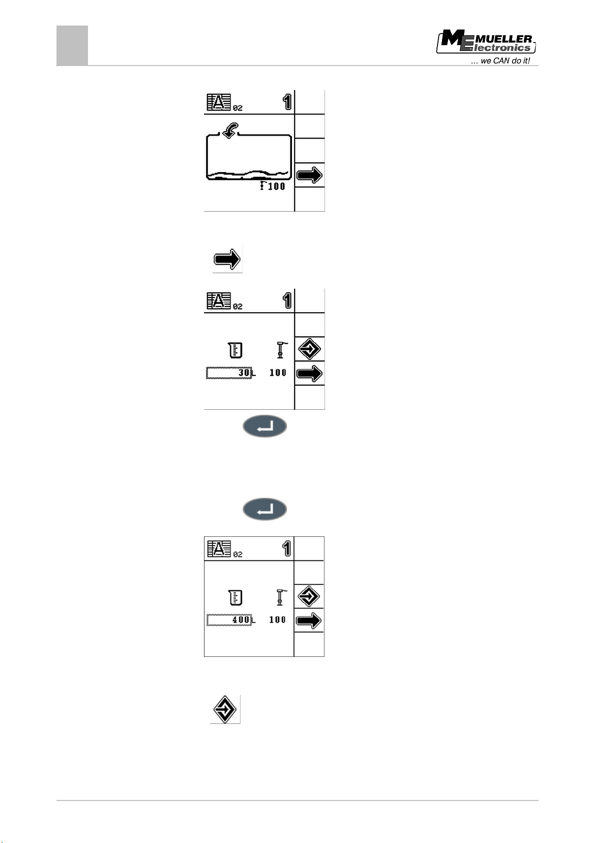
⇨ The sensor level changes:
⇨ You have reached calibration point 02.
⇨ The float height is 100mm.
15. Press:
⇨ The following screen will appear:
16. Press this key:
⇨ The data input screen appears.
17. Enter the current tank fill level. In the example, we assume a fill level of exactly 400 litres.
18. Write down the current fill level.
19. Press this key:
⇨ The following screen will appear:
⇨ You have entered the fill level for calibration point 02.
20. Repeat steps 13 to 19 for a maximum of 30 calibration points in total.
21. Press
when you have finished all the calibration points.
Page 35
Copyright © Müller-Elektronik GmbH & Co.KG
35
8.5.3
"Sensors" menu - configuration and calibration
Carrying out calibration
8
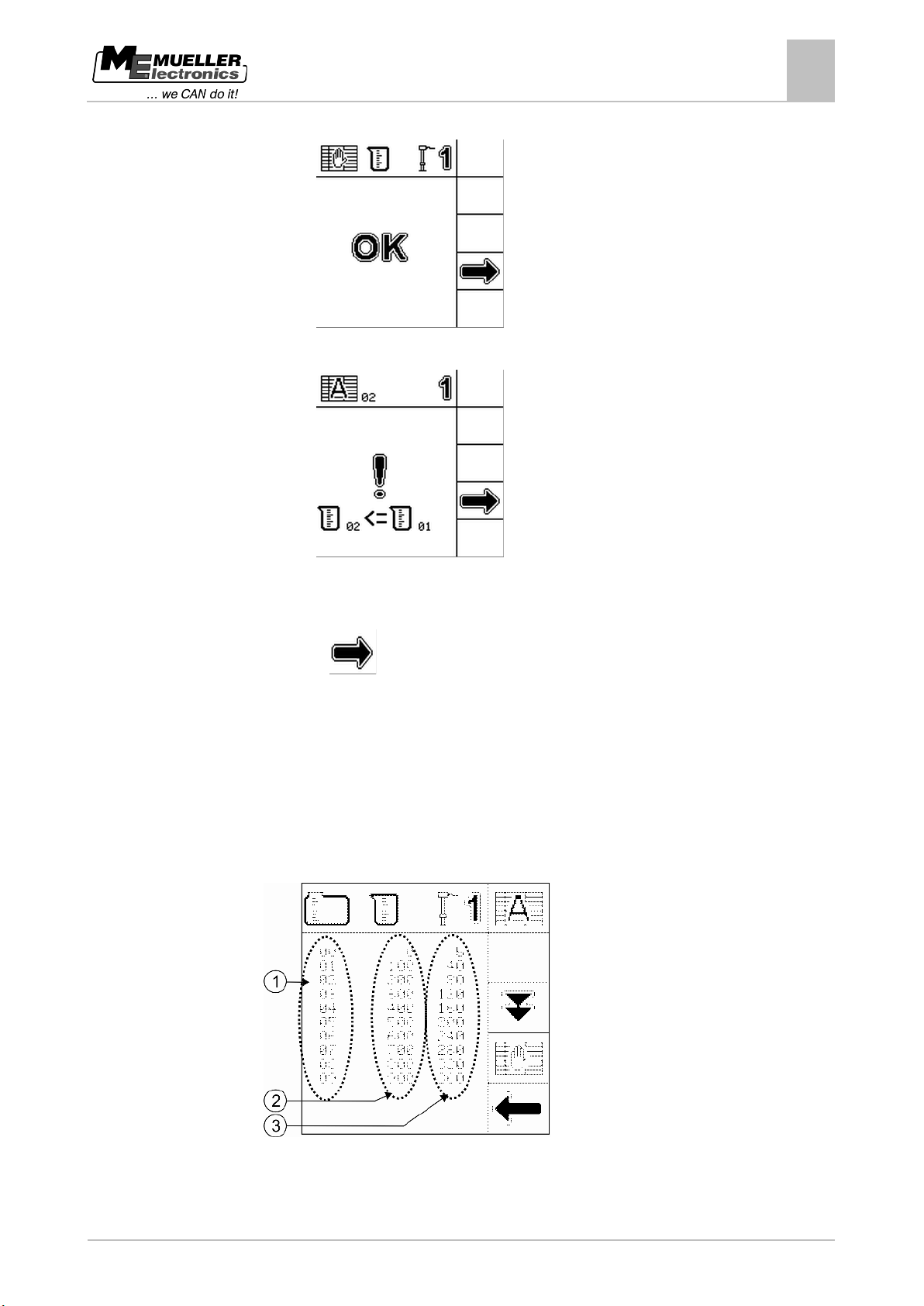
⇨ One of the following screens appears:
Calibration was successful.
⇨ OR
Calibration was not successful. In the example, the fill level at calibration point 02 is lower
than at calibration point 01.
In this case, you must check the values entered and correct them manually.
22. Press:
⇨ You have completed automatic calibration.
Entering calibration values manually
You can input calibration values manually if you have already carried out automatic calibration on an
identical tank and know the fill level at each float height.
To save time, you can enter the individual values without filling the tank.
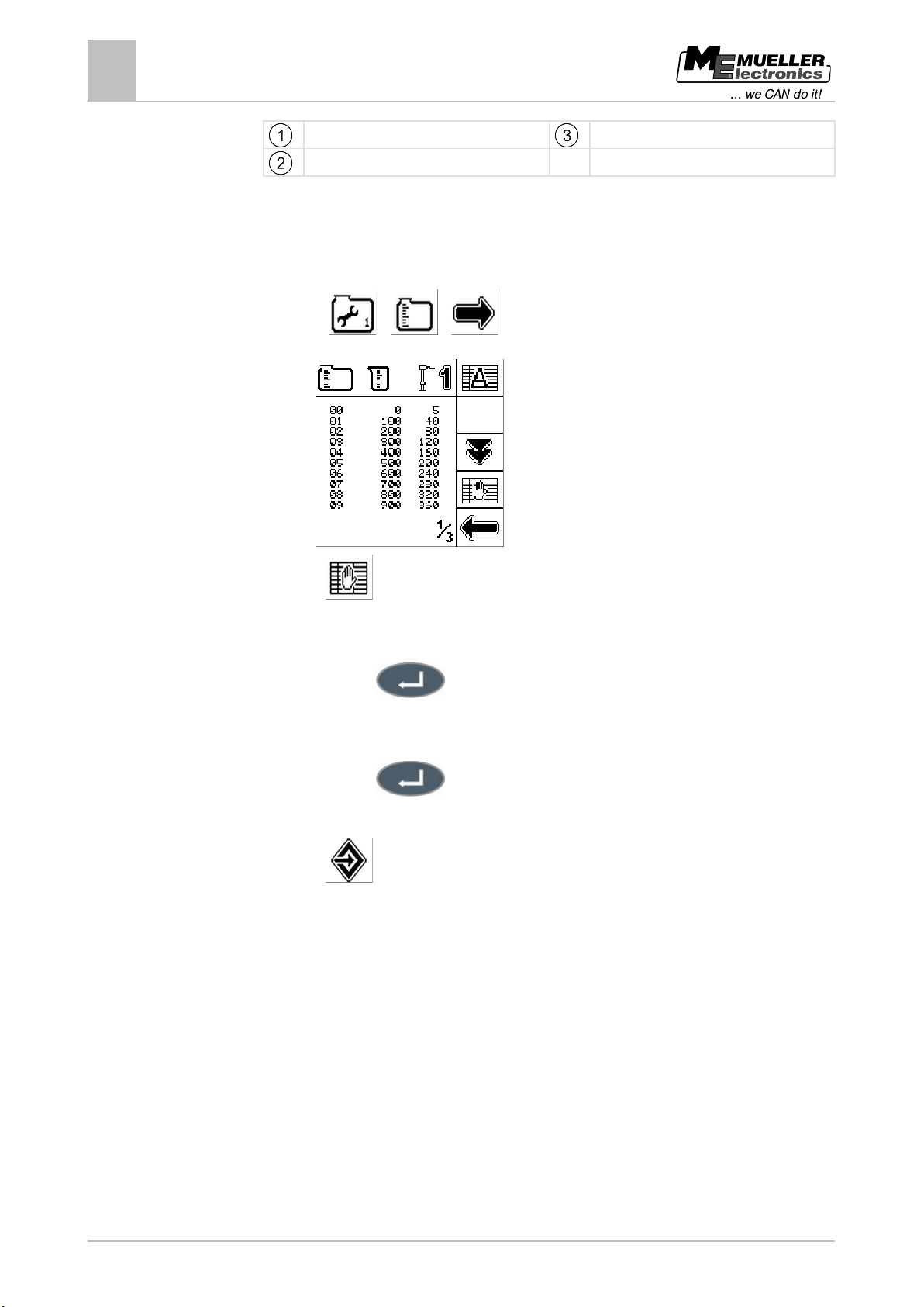
During the manual input process you will see the following screen:
Overview of calibration points with fill levels and float heights
Page 36
36
Copyright © Müller-Elektronik GmbH & Co.KG
Procedure
8.6
"Sensors" menu - configuration and calibration
8
Setting the sensor sensitivity
Calibration points
Float height in mm
Fill level in l
You have set the tank size.
You have calibrated an identical tank and have the individual values to hand.
1. Open the "Sensors" menu.
2. Press:
> >
⇨ The following screen will appear:
3. Press
to activate manual input.
⇨ A cursor appears on the screen.
4. Select the fill level or float height that you want to change.
5. Press this key:
⇨ The data input screen appears.
6. Enter the settings required. Use the values from the identical tank.
7. Press this key:
8. Repeat steps 4 to 7 for all the values you want to change.
9. Press
⇨ You have completed the manual input process.
when you have finished inputting the data.
Setting the sensor sensitivity
The liquid in the tank moves during travel. This means that the float position also changes constantly.
You will see that the fill level on the display increases and decreases all the time.
If the sensor is too sensitive to water movement, you can reduce its sensitivity.
If the sensitivity is high, the fill levels displayed are updated faster. If the sensitivity is low, the fill
levels displayed are updated more slowly.
Page 37
Copyright © Müller-Elektronik GmbH & Co.KG
37
filter
Minimum float position
Function icon
Sensitivity
Procedure
"Sensors" menu - configuration and calibration
Setting the sensor sensitivity
8
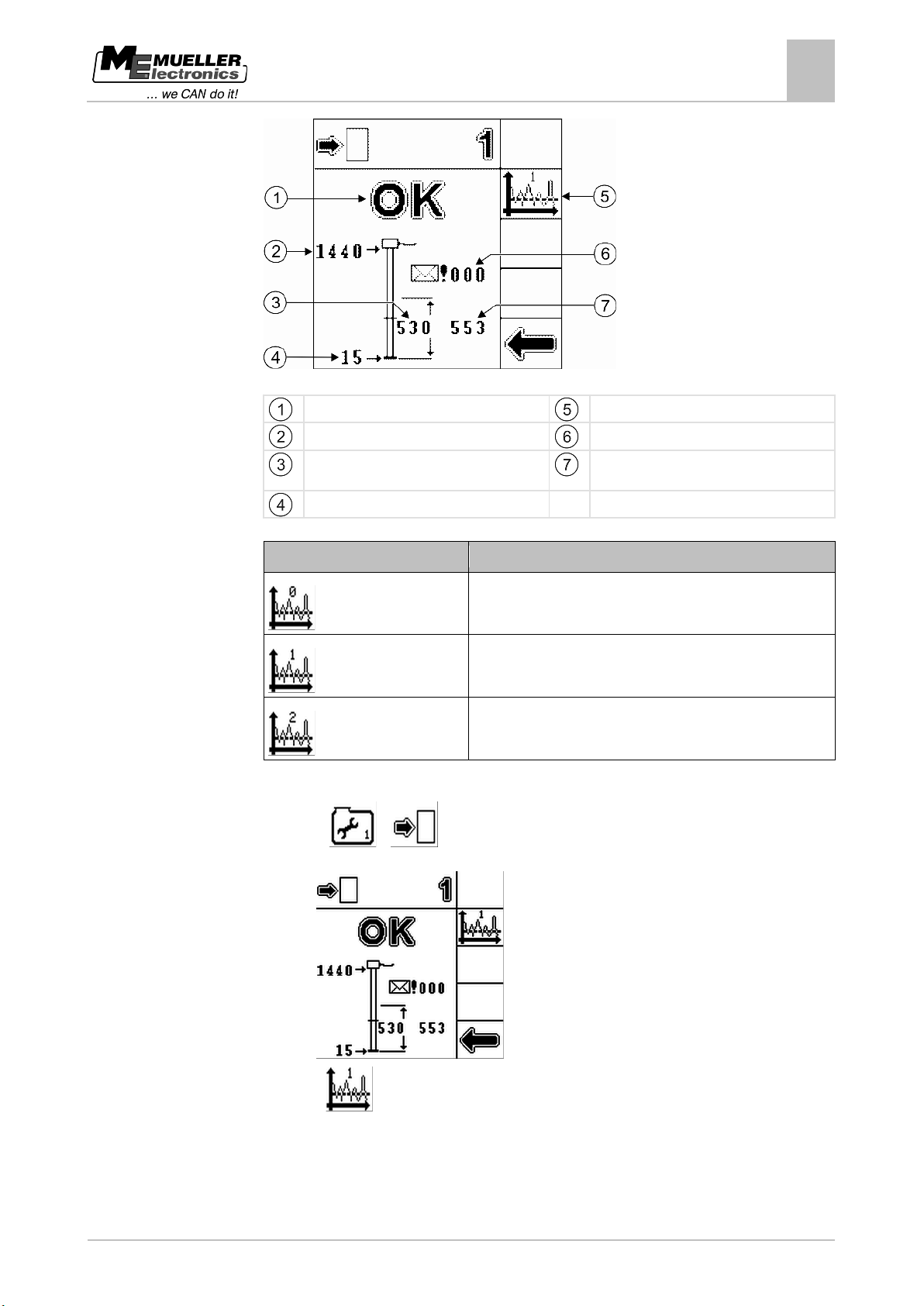
Sensor data display
Status
Sensitivity level selected
Maximum float position
Current float position
Number of errors
Current float position, taking account of the
High sensor sensitivity
Normal sensor sensitivity
Low sensor sensitivity
1. Open the "Sensors" menu.
2. Press:
>
⇨ The following screen will appear:
3. Press
to change the sensor sensitivity.
⇨ The function icon also shows which sensitivity level is currently selected.
Page 38
38
Copyright © Müller-Elektronik GmbH & Co.KG
Tank selected for calculation of workable area
Fill level of tank 2
Set filling for tank 2
9
9.1
"Tank Control II" menu - Filling and operation
9
Opening the "Tank Control II" menu
"Tank Control II" menu - Filling and operation
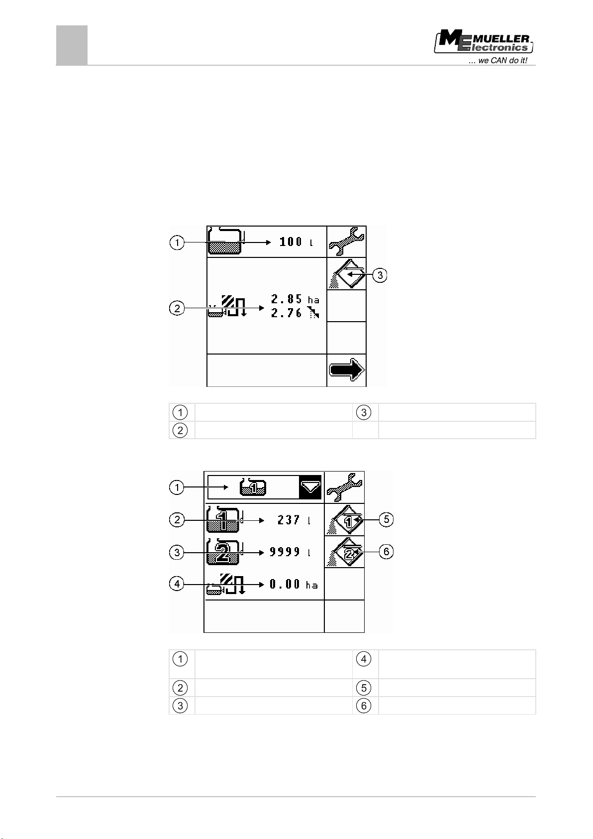
The "Tank Control II" menu will look different depending on whether you are using one tank and one
sensor or two tanks and two sensors. If you are using two tanks and two sensors you can choose
which tank you want to use.
In the "Tank Control II" menu you can:
▪ Fill the tank.
▪ Read the fill level in the tank.
▪ Calculate application rates.
If you are using one tank and one sensor, the "Tank Control II" menu looks like this:
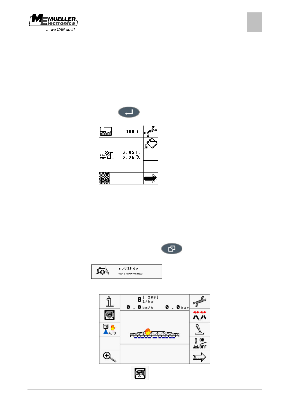
"Tank Control II" menu for one tank
Tank fill level
Workable area without and with overlaps
Set filling
If you are using two tanks and two sensors, the "Tank Control II" menu looks like this:
"Tank Control II" menu for two tanks
[➙ 44]
Fill level of tank 1
Workable area [➙ 44]
Set filling for tank 1
Opening the "Tank Control II" menu
You can open the "Tank Control II" menu:
Page 39
Copyright © Müller-Elektronik GmbH & Co.KG
39
9.1.1
Procedure
9.1.2
Procedure
"Tank Control II" menu - Filling and operation
Opening the "Tank Control II" menu
9
▪ On the control unit
▪ On the terminal in the tractor cab
Opening the "Tank Control II" menu on the control unit
To open the "Tank Control II" menu on the control unit:
1. Start the control unit.
⇨ The start screen appears.
2. Select the "Tank Control II" line
3. Press this key:
⇨ The following screen will appear:
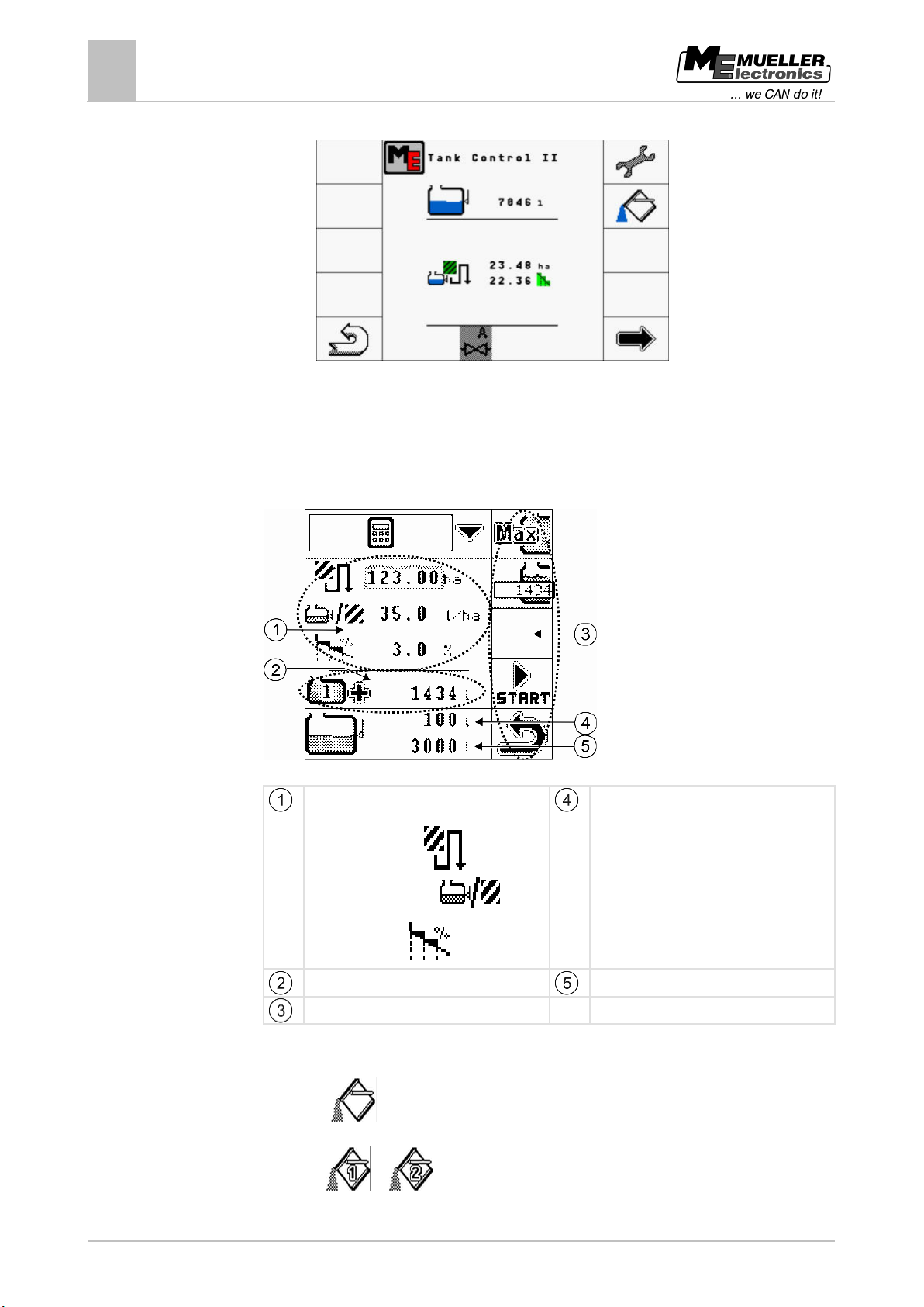
⇨ From this screen you can access all the other screens you need for filling.
Opening the "Tank Control II" menu on the terminal in the tractor cab
To open the "Tank Control II" menu on the terminal in the tractor cab:
1. Start the terminal in the tractor cab and the control unit.
2. Open the "Tank Control II" menu on the control unit.
3. On the terminal in the tractor cab press
to open the selection menu.
4. On the terminal, select the line for the job computer:
5. Open the work screen for the job computer on the terminal.
⇨ The following screen appears on the terminal:
6. On the terminal press:
Page 40
40
Copyright © Müller-Elektronik GmbH & Co.KG
- realistic overlap
9.2
Procedure
"Tank Control II" menu - Filling and operation
9
Calculating the volume of spray required
⇨ The following screen appears on the terminal:
⇨ From this screen you can access all the other screens you need for filling.
Calculating the volume of spray required
With TANK-Control II you can calculate how much spray liquid you need to spray the field and how
often you will need to fill the tank.
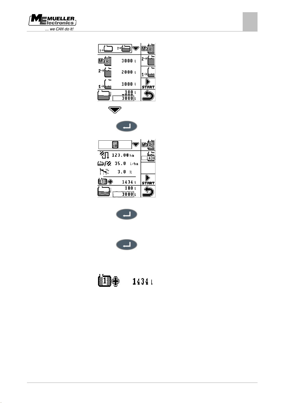
Calculator for working out the volume of spray required
Data required for the calculation. You need to
know the following information in advance:
Current fill level
- area to be sprayed
- planned application rate
Volume of spray required
Function icons
1. Open the "Tank Control II" menu.
2. Press:
OR
Press
Tank size
if you are using one tank.
or if you are using two tanks.
Page 41
Copyright © Müller-Elektronik GmbH & Co.KG
41
9.3
"Tank Control II" menu - Filling and operation
Filling the tank
9
⇨ The following screen will appear:
3. Select the
4. Press this key:
icon in the upper area of the screen.
⇨ The following screen will appear:
5. Select the value you want to change.
6. Press this key:
⇨ The data input screen appears.
7. Enter the settings required.
8. Press this key:
9. Repeat steps 5 to 8 for all the values you want to change.
⇨ The lower area of the screen shows how many full tanks you will need.
⇨ It also shows the volume that will be required in the last tank, in this case:
– one full tank + 1434l.
Filling the tank
You can fill a tank manually or with the help of external devices. If you intend to use external devices,
they must be connected to the TANK-Control II system. TANK-Control II can end filling automatically
if it is controlling external devices.
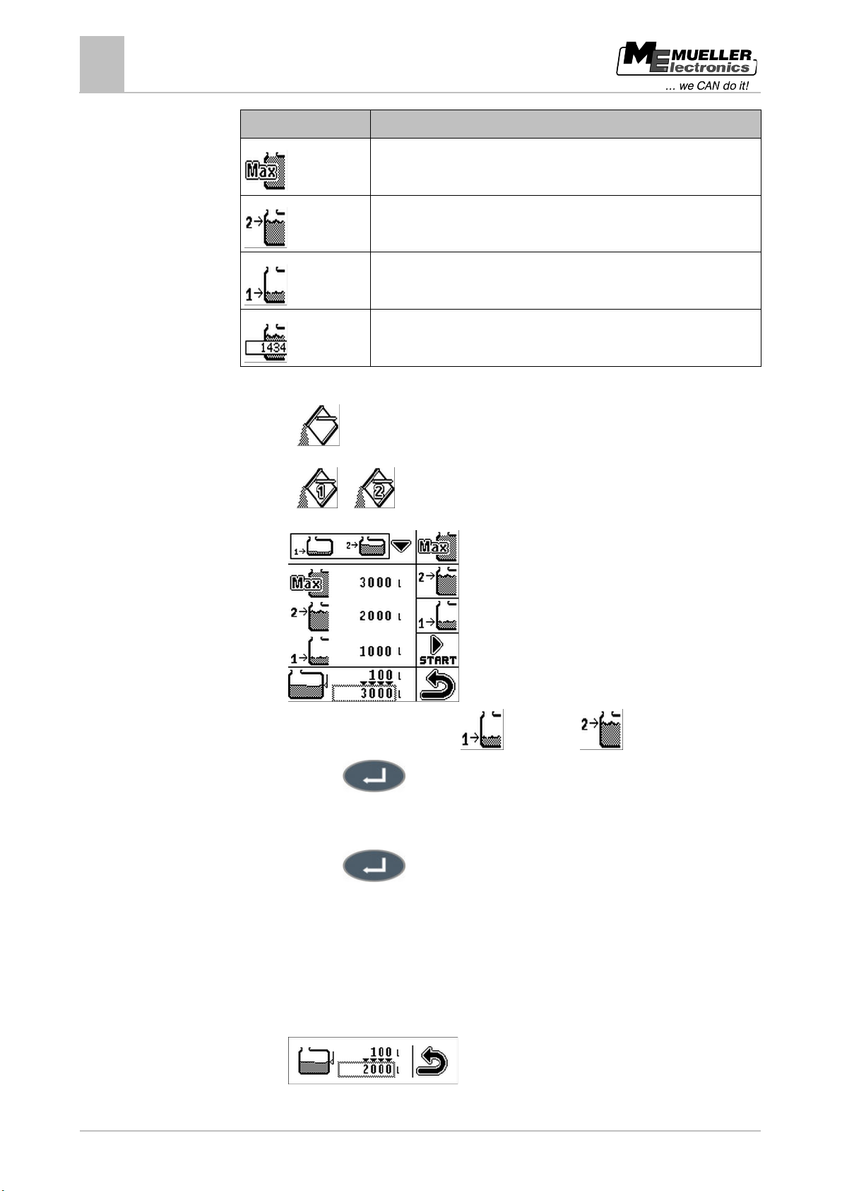
Before filling the tank, you can define two fill limits:
▪ One fill limit if you are adding one product to the tank.
▪ Two fill limits if you are adding two products to the tank.
Note that the value for fill limit 2 must always be higher than the value for fill limit 1.
During filling, you can choose between the following fill limits:
Page 42
42
Copyright © Müller-Elektronik GmbH & Co.KG
Function icon
Meaning
Procedure
"Tank Control II" menu - Filling and operation
9
Filling the tank
Set maximum fill.
Set filling up to fill limit 2
Set filling up to fill limit 1
Set the part tank volume required for the remaining area as a fill limit.
Calculate the volume of spray required before doing this.
1. Open the "Tank Control II" menu.
2. Press
if you are using one tank.
OR
Press
or if you are using two tanks.
⇨ The following screen will appear:
3. Select the fill level you want to define.
4. Press this key:
⇨ The data input screen appears.
5. Set the fill level for the fill limit selected.
– fill level 1 or – fill level 2.
6. Press this key:
7. Repeat steps 3 to 6 for the other fill level. If you are just using one product, set the maximum fill
level for fill level 2.
⇨ You have defined the fill levels.
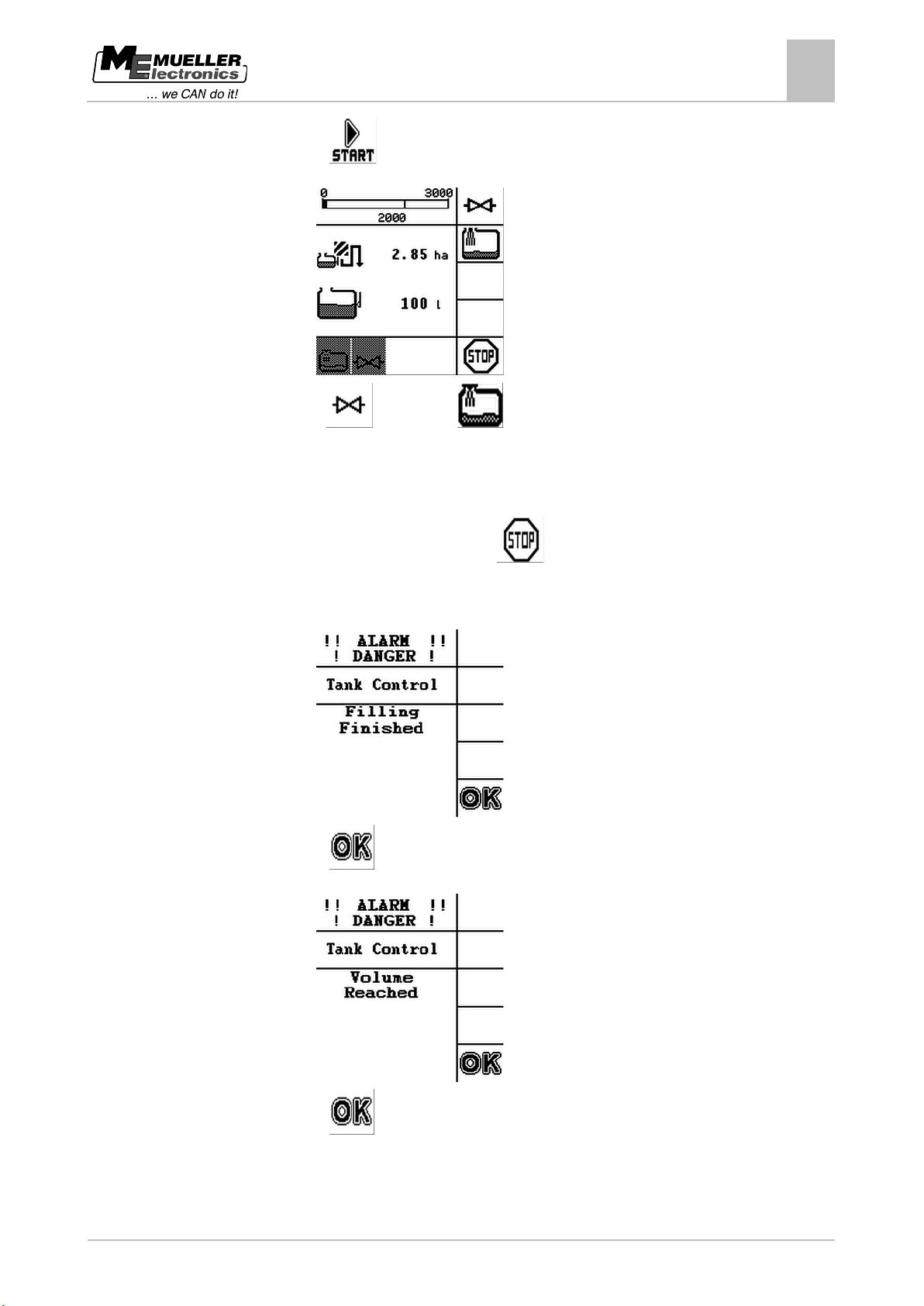
8. Press the function key with the fill limit to which you want to fill the tank. If you want to set the
part tank volume required for the remaining area as a fill limit, you need to switch to the
calculation screen.
⇨ The volume to be added to the tank, shown in the lower area of the screen, changes:
Page 43
Copyright © Müller-Elektronik GmbH & Co.KG
43
"Tank Control II" menu - Filling and operation
Filling the tank
9
9. Press:
⇨ The following screen will appear:
10. Press
– ball valve or – filling pump to activate or deactivate the external
devices.
⇨ The lower area of the screen shows whether the external devices are activated. [➙ 45]
11. Fill the tank up to the fill limit selected.
12. When you want to stop filling, press:
⇨ The main area of the screen shows the area that you can spray with the current fill level.
⇨ When the required volume has been added to the tank, you will hear a beep and the
following screen appears:
13. Press:
⇨ The following screen will appear:
14. Press:
⇨ You have filled the tank to the fill limit selected.
Page 44
44
Copyright © Müller-Elektronik GmbH & Co.KG
Display
Meaning
the spray liquid from tank 1.
the spray liquid from tank 2.
9.4
Procedure
9.5
9.5.1
"Tank Control II" menu - Filling and operation
9
Displaying the workable area
Displaying the workable area
If you are using one tank and one sensor, the workable area is displayed by default in the "Tank
Control II" menu.
If you are using two tanks and two sensors, you can display the workable area in the "Tank Control II"
menu as follows:
Area that you can spray with the fill level in tank 1. For example, if you only apply
Area that you can spray with the fill level in tank 2. For example, if you only apply
Total area that you can spray. For example, if you apply the same spray liquid
from both tanks.
To change the display if you are using TANK-Control II with two tanks and two sensors:
1. Open the "Tank Control II" menu.
2. Press the
key until you can see the tank required or both tanks for use in the
calculation.
⇨ The workable area display changes depending on what you select.
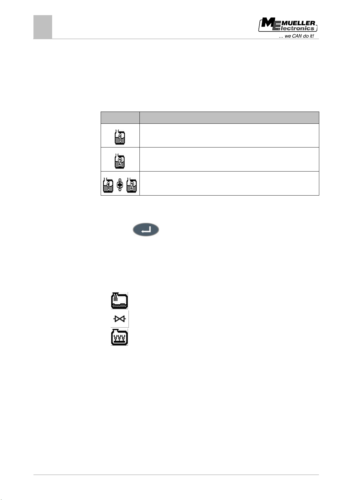
Controlling external devices
TANK-Control II can control operation of the following external devices:
▪
▪
▪
Activating and deactivating external devices
When using external devices, you can select whether the devices are activated or deactivated.
- Filling pump
- Ball valve
- Agitator
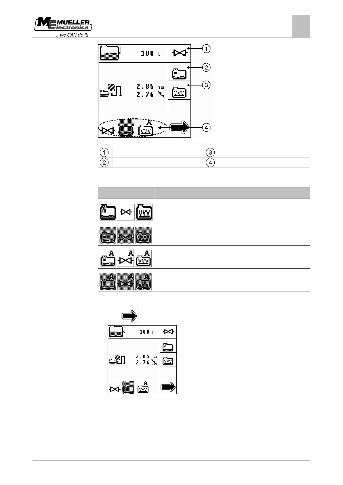
You can activate or deactivate all external devices on the following screen:
Page 45
Copyright © Müller-Elektronik GmbH & Co.KG
45
Icons
Meaning
Procedure
"Tank Control II" menu - Filling and operation
Controlling external devices
9
Screen: Activation and deactivation
Activate or deactivate ball valve.
Activate or deactivate agitator.
Activate or deactivate filling pump.
The following settings are available when using external devices:
Current external device setting.
Activated and in manual mode.
Deactivated and in manual mode.
Activated and in automatic mode.
Deactivated and in automatic mode.
1. Open the "Tank Control II" menu.
2. Press
until the following screen appears:
⇨ The screen now displays the external devices that are connected to the system.
3. Press the function icon for the external devices that you want to activate or deactivate.
⇨ The lower area of the screen shows whether the external devices are activated or deactivated.
Page 46
46
Copyright © Müller-Elektronik GmbH & Co.KG
case: not activated.
appears here.
case: activated.
here.
9.5.2
Procedure
"Tank Control II" menu - Filling and operation
9
Controlling external devices
Changing the mode of the external devices
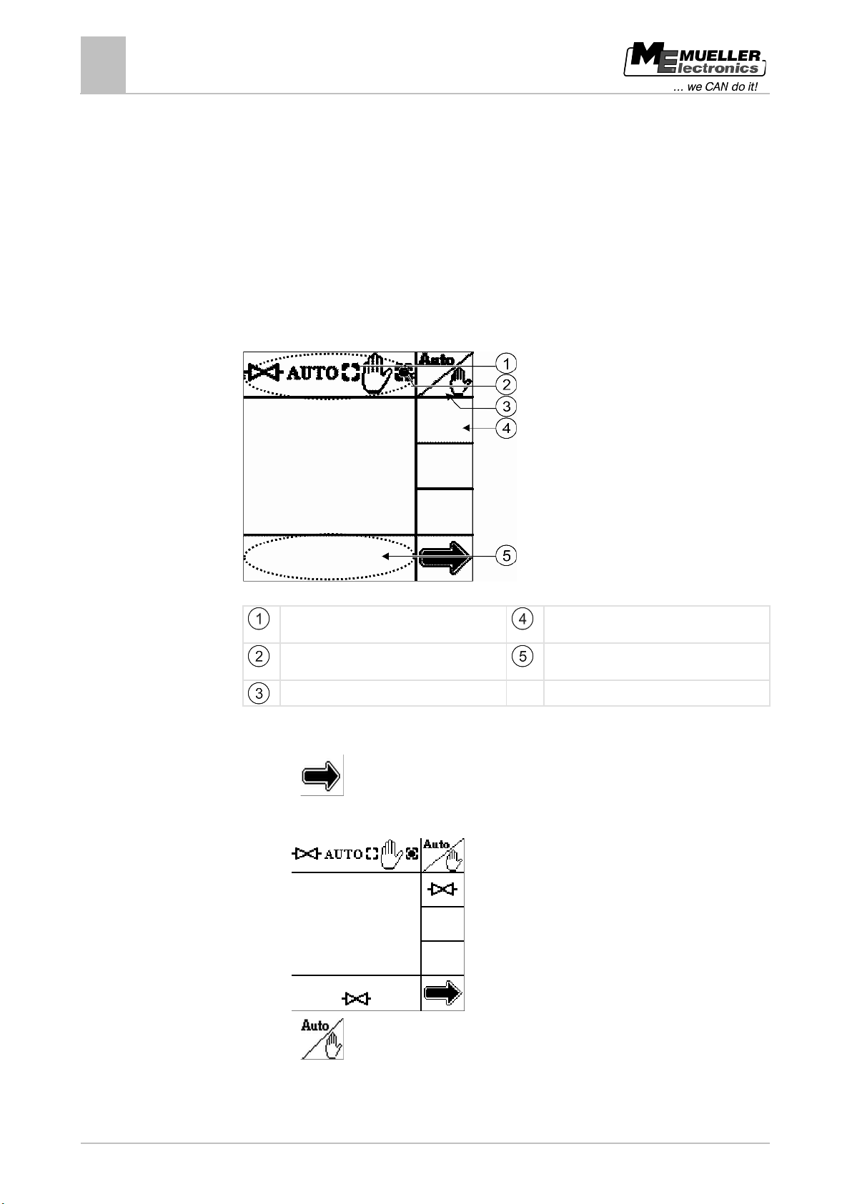
When using external devices, you can select how you use the external devices. You can choose
between two modes:
▪ Manual mode
You have to activate and deactivate the external devices manually.
▪ Automatic mode
TANK-Control II switches the external devices on and off.
– The external devices are activated when you start filling the tank.
– The external devices are deactivated when you or TANK-Control II stop filling the tank.
External devices screen
External device is in automatic mode, in this
External device is in manual mode, in this
Change mode.
The function icon for the external device
The status of the external device appears
1. Open the "Tank Control II" menu.
2. Press
until you can see the function icon for the external device that you want to control,
in this case: a ball valve.
⇨ The following screen will appear:
3. Press
to switch between manual and automatic mode.
⇨ The mode selected is displayed in the upper and lower areas of the screen. [➙ 45]
Page 47
Copyright © Müller-Elektronik GmbH & Co.KG
47
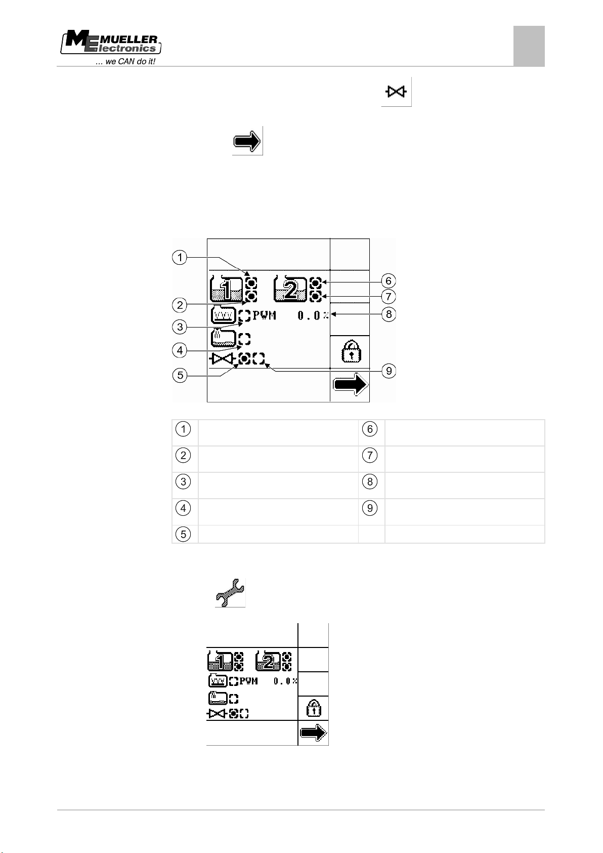
in this case: connected
in this case: connected
1, in this case: connected
2, in this case: not connected
deactivated.
control and deactivated.
9.5.3
Procedure
"Tank Control II" menu - Filling and operation
Controlling external devices
9
4. To activate or deactivate the external device, press:
⇨ The status of the external device is displayed in the lower area of the screen. [➙ 45]
⇨ Press:
⇨ You have changed the mode of the external device.
Viewing the configuration of the external devices
You can display an overview of external device configuration.
Overview of external devices
Overflow sensor from manufacturer of tank 1,
Overflow sensor from manufacturer of tank 2,
Empty tank sensor from manufacturer of tank
Agitator, in this case: with speed control and
Filling pump, in this case: without speed
Empty tank sensor from manufacturer of tank
Current agitator speed in percent.
Ball valve is open, in this case: deactivated.
Ball valve is shut, in this case: activated.
1. Open the "Tank Control II" menu.
2. Press:
⇨ The following screen will appear:
3. Check that all the external devices are connected correctly and are activated or deactivated.
Page 48
48
Copyright © Müller-Elektronik GmbH & Co.KG
key
minimum speed
filling pump.
9.5.4
"Tank Control II" menu - Filling and operation
9
Controlling external devices
Using a filling pump
There are two types of filling pump:
▪ Filling pump with on/off valve
▪ Filling pump with rotary speed control
The settings that you can enter differ according to the type of filling pump. The following settings are
available:
Function icon or
Meaning
Change mode
Change status
Increase speed
Reduce speed
Set on-time before reaching maximum speed and off-time before reaching
Filling pump with rotary speed control
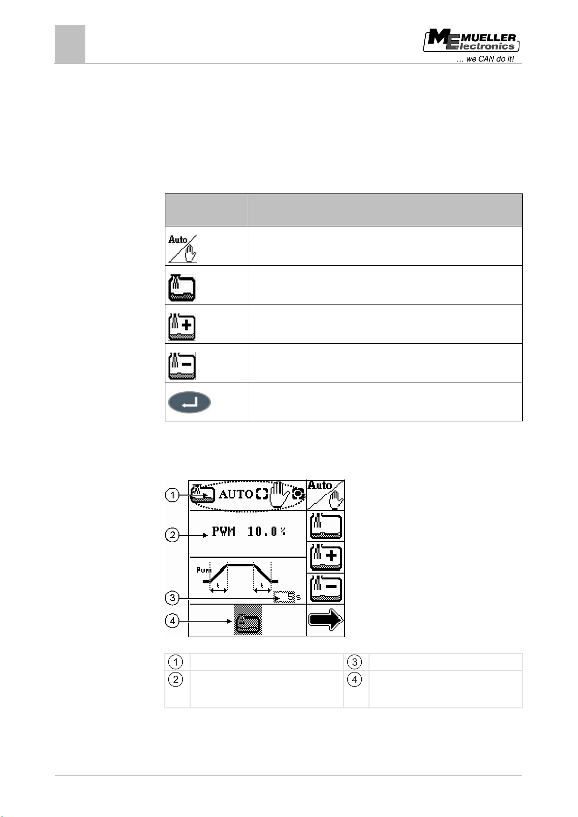
If you are using a filling pump with rotary speed control, you will see the following screen:
Screen: Filling pump with rotary speed control
Mode
PWM value
The PWM value controls the speed of the
On-time and off-time selected
Status [➙ 45]
You can enter the following settings:
Page 49
Copyright © Müller-Elektronik GmbH & Co.KG
49
key
9.5.5
"Tank Control II" menu - Filling and operation
Controlling external devices
9
▪ You can set a PWM value. The PWM value entered indicates the percentage of maximum filling
pump speed during operation, in this case: 10%.
▪ You can set the on-time that the filling pump should take to reach the specified PWM value. The
same time is used to switch the filling pump off, in this case: 5 seconds.
Using a ball valve
You can use a ball valve in two ways:
▪ Without additional filling pump
▪ With additional filling pump
The settings that you can enter differ according to the method of use of the ball valve. The following
settings are available:
Function icon or
Meaning
Change mode
Change status
Set the start time of the ball valve and filling pump relative to one another
Set the stop time of the ball valve and filling pump relative to one another
Set time-controlled start or stop
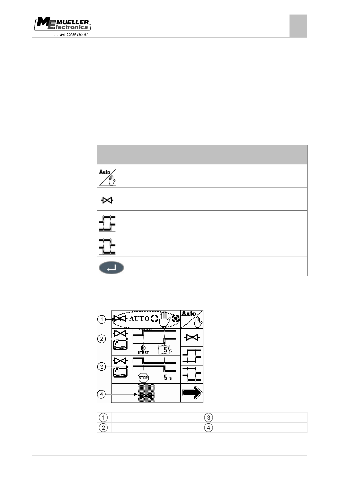
Ball valve with filling pump
If you are using a ball valve with additional filling pump, you will see the following screen:
Screen: Ball valve with filling pump
Mode
Start time
Stop time
Status [➙ 45]
Page 50
50
Copyright © Müller-Elektronik GmbH & Co.KG
Start time icon
Meaning
Stop time icon
Meaning
key
9.5.6
"Tank Control II" menu - Filling and operation
9
Controlling external devices
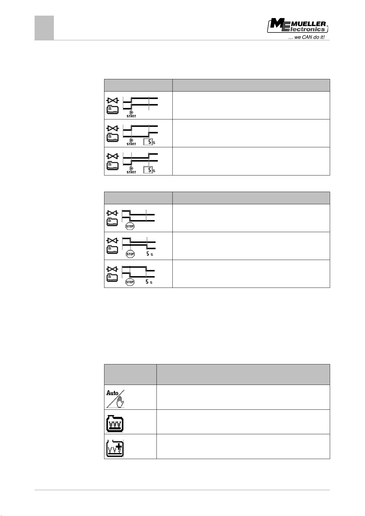
You can set the start or stop time of the two devices relative to one another. The options are shown in
the two tables below:
Set the start time
The ball valve opens when the filling pump starts.
The ball valve opens before the filling pump starts, in this case: 5
seconds earlier.
The ball valve opens after the filling pump has reached the set
speed, in this case: 5 seconds later.
Set the stop time
The ball valve shuts when the filling pump stops.
The ball valve shuts before the filling pump stops, in this case: 5
seconds earlier.
The ball valve shuts after the filling pump has switched off, in this
case: 5 seconds later.
Using an agitator
There are two types of agitator:
▪ Agitator with on/off valve
▪ Agitator with rotary speed control
The settings that you can enter differ according to the type of agitator. The following settings are
available:
Function icon or
Meaning
Change mode
Change status
Increase speed
Page 51
Copyright © Müller-Elektronik GmbH & Co.KG
51
key
"Tank Control II" menu - Filling and operation
Controlling external devices
9
Function icon or
Meaning
Reduce speed
Define minimum or maximum fill level
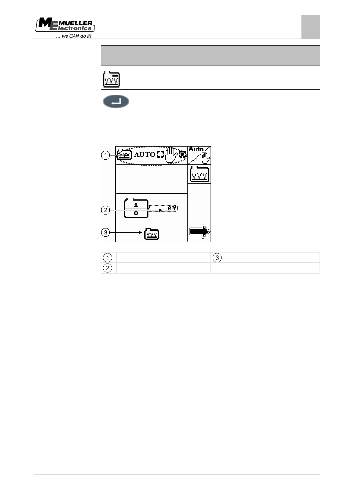
Agitator with on/off valve
If you are using an agitator with an on/off valve, you will see the following screen:
Screen: Agitator with on/off valve
Mode
Minimum fill level
Status [➙ 45]
You can enter the following settings:
▪ You can define a minimum fill level, in this case: 100l
If you have defined a minimum fill level in automatic mode, TANK-Control II takes care of the
following tasks:
– Switches the agitator off when the fill level falls below the defined minimum fill level.
– Switches the agitator on when the fill level rises above the defined minimum fill level.
Agitator with rotary speed control
If you are using an agitator with rotary speed control, you will see the following screen:
Page 52
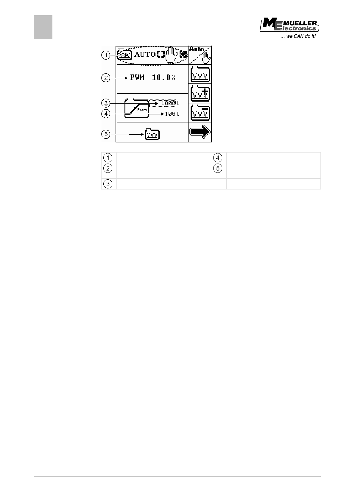
52
Copyright © Müller-Elektronik GmbH & Co.KG
The PWM value controls the agitator speed.
"Tank Control II" menu - Filling and operation
9
Controlling external devices
Screen: Agitator with rotary speed control
Mode
Minimum fill level
PWM value
Status [➙ 45]
Maximum fill level
You can enter the following settings:
▪ You can set a PWM value. The PWM value entered indicates the percentage of maximum
agitator speed during operation, in this case: 10%.
▪ You can define a minimum and a maximum fill level, in this case: 100l and 1000l.
In manual mode, the following setting is used:
– The PWM value for control of the rotary speed corresponds to the value you have entered.
In automatic mode, TANK-Control II applies the following calculations:
– The agitator is switched off when the fill level falls below the defined minimum fill level.
– The agitator operates at optimum capacity when the fill level is between the defined fill
levels.
– The agitator operates at the maximum capacity specified when the fill level is above the
defined maximum fill level.
Page 53
Copyright © Müller-Elektronik GmbH & Co.KG
53
10
10.1
Procedure
Using two sensors
Adding a second sensor
10
Using two sensors
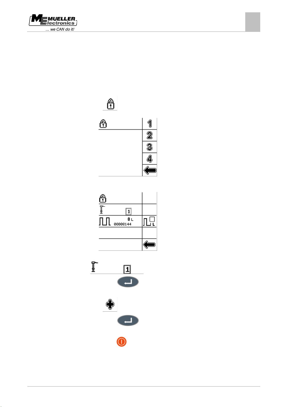
If you use two tanks on your field sprayer, you can use TANK-Control II with two sensors.
Adding a second sensor
If you want to configure a second sensor, the procedure is as follows:
1. Open the "Sensors" menu.
2. Press:
⇨ The following screen will appear:
3. Enter the password (14232314).
⇨ The following screen will appear:
4. Select:
5. Press this key:
⇨ The data input screen appears.
6. Press:
7. Press this key:
⇨ The control unit switches off.
8. Press this key
to switch the control unit on.
⇨ You have added the second sensor.
⇨ You need to configure the second sensor.
Page 54
54
Copyright © Müller-Elektronik GmbH & Co.KG
10.2
Procedure
Using two sensors
10
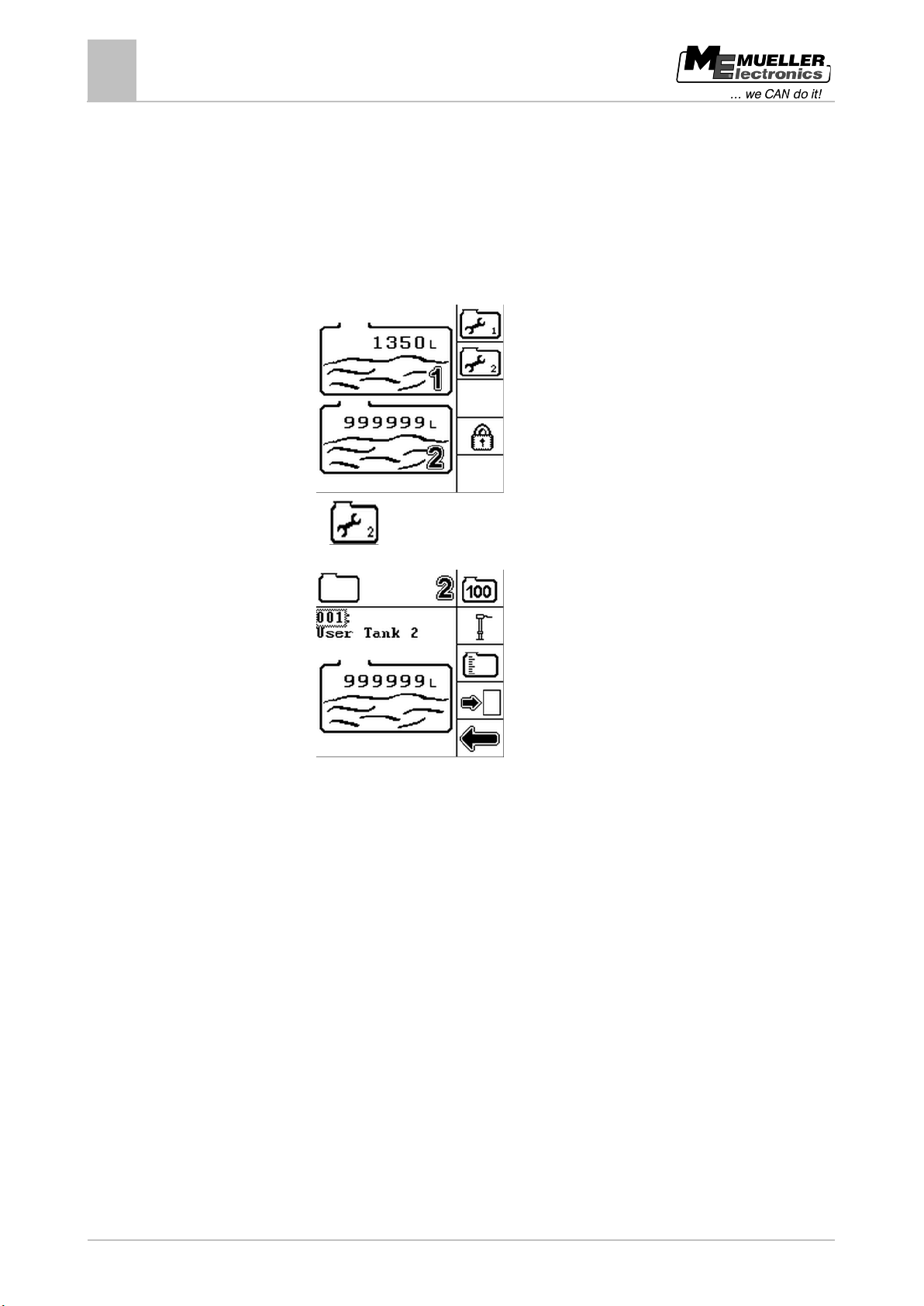
Configuring the second sensor
Configuring the second sensor
The procedure for configuring the second sensor is exactly the same as for the first sensor. You just
have to select the sensor you want to calibrate.
1. Open the "Sensors" menu.
⇨ The "Sensors" menu appears with a second tank. The menu also has a function icon for the
second configuration.
2. Press:
⇨ The following screen will appear:
3. Carry out the complete configuration and calibration process for the second tank. [➙ 25]
Page 55
Copyright © Müller-Elektronik GmbH & Co.KG
55
11
11.1
Procedure
Configuring external devices
Configuring a filling pump
11
Configuring external devices
This section of the Operating Instructions is intended for service technicians only. Expertise in
configuring filling pumps, ball valves and agitators is essential.
Configuring a filling pump
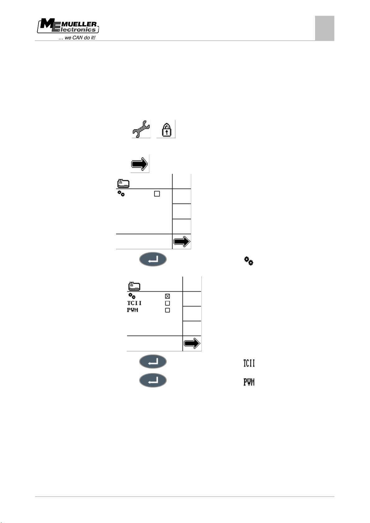
1. Open the "Tank Control II" menu.
2. Press:
>
3. Enter the password (14232314).
4. Press
until the following screen appears:
5. Press the
key to activate this selection field if a filling pump is used.
⇨ The screen changes:
6. Press the
7. Press the
key to activate this selection field .
key to activate this selection field if the filling pump has a PWM
actuator. A PWM actuator can be used to regulate the filling pump speed.
OR
Continue with step 14 if the filling pump has an on/off valve.
Page 56
56
Copyright © Müller-Elektronik GmbH & Co.KG
11.2
Procedure
Configuring external devices
11
Configuring a ball valve
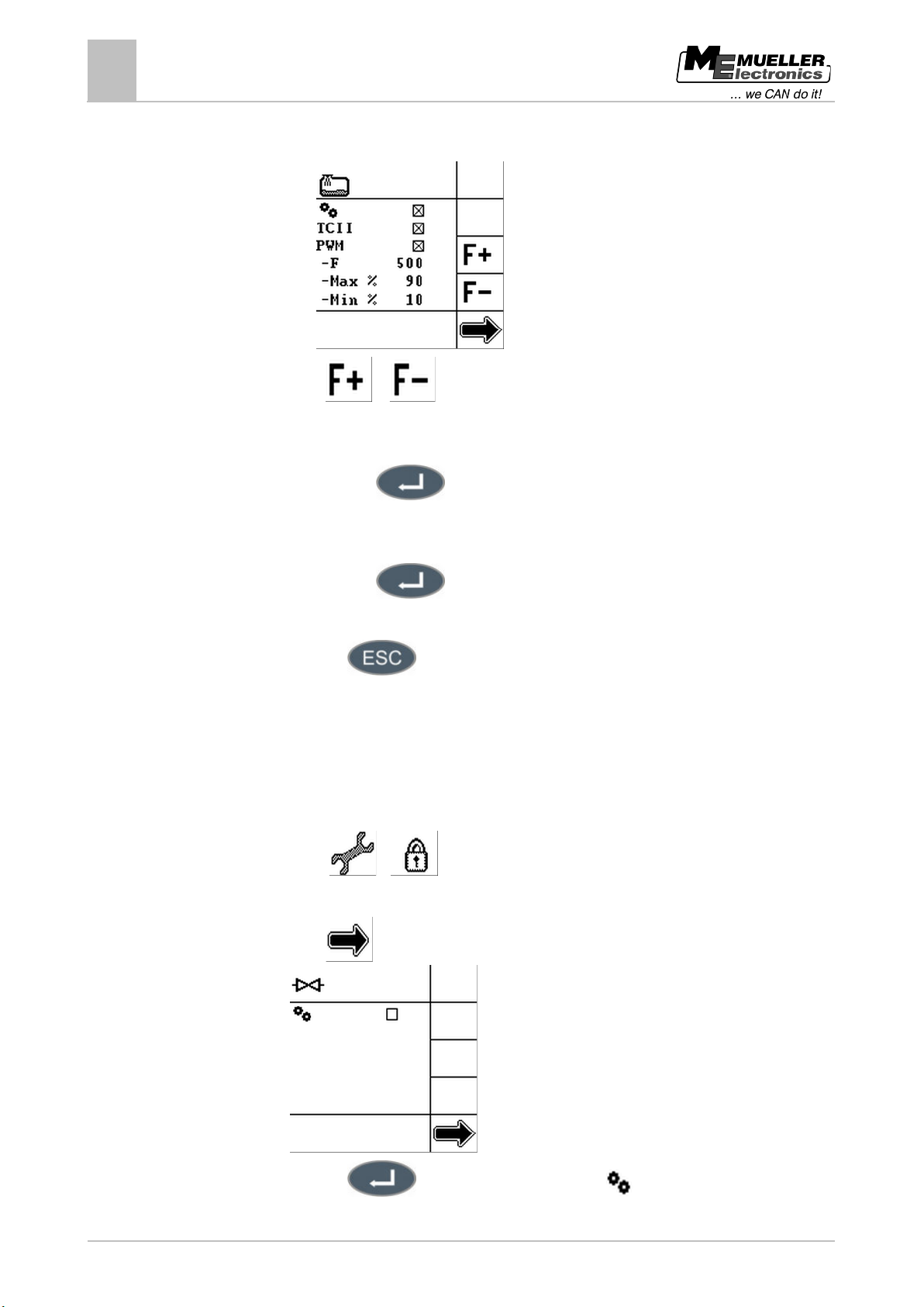
⇨ If the filling pump has a PWM actuator and you have activated the selection field, the screen
changes:
8. Press
or to set the PWM frequency. You will find the correct PWM frequency in
the technical specifications for the filling pump. In this case, the PWM frequency is 500Hz.
9. Select the relevant percentage to change the maximum or minimum filling pump speed.
10. Press this key:
⇨ The data input screen appears.
11. Enter the percentage required.
12. Press this key:
13. Repeat steps 9 to 12 for the other percentage.
14. Press the
key to save the settings.
⇨ TANK-Control II switches off.
15. Restart TANK-Control II to use the new settings.
Configuring a ball valve
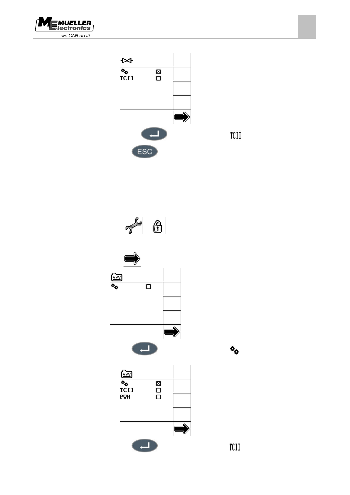
1. Open the "Tank Control II" menu.
2. Press:
>
3. Enter the password (14232314).
4. Press
until the following screen appears:
5. Press the
key to activate the selection field if a ball valve is used.
Page 57
Copyright © Müller-Elektronik GmbH & Co.KG
57
11.3
Procedure
Configuring external devices
Configuring an agitator
11
⇨ The screen changes:
6. Press this key
7. Press the
to activate the selection field .
key to save the settings.
⇨ TANK-Control II switches off.
8. Restart TANK-Control II to use the new settings.
Configuring an agitator
1. Open the "Tank Control II" menu.
2. Press:
>
3. Enter the password (14232314).
4. Press
until the following screen appears:
5. Press the
⇨ The screen changes:
6. Press the
key to activate the selection field if an agitator is used.
key to activate the selection field .
Page 58
58
Copyright © Müller-Elektronik GmbH & Co.KG
Configuring external devices
11
Configuring an agitator
7. Press the key to activate the selection field if the agitator has a PWM actuator.
A PWM actuator can be used to regulate the speed of the agitator.
OR
Continue with step 14 if the agitator has an on/off valve.
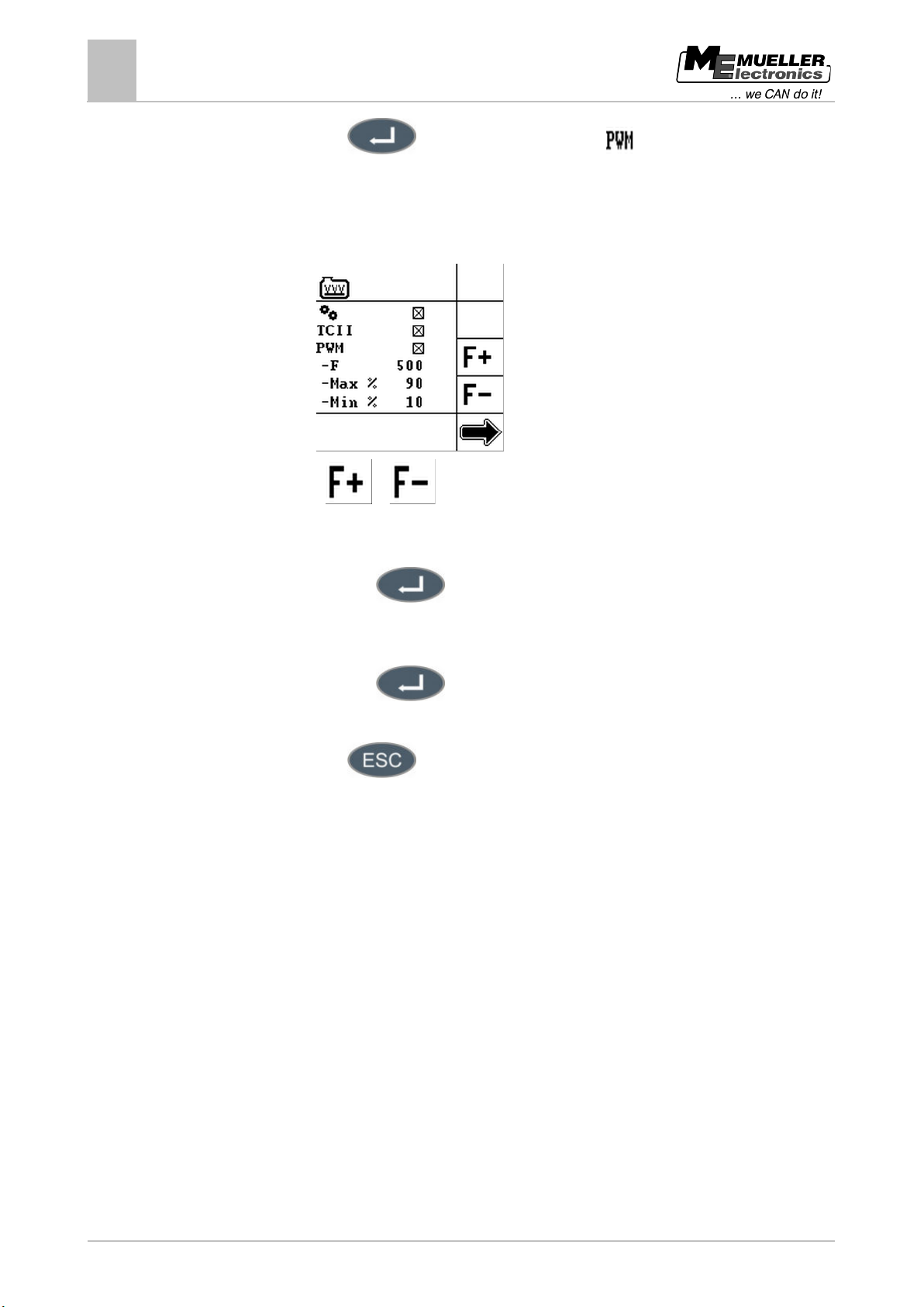
⇨ If the agitator has a PWM actuator and you have activated the selection field, the screen
changes:
8. Press
or to set the PWM frequency. You will find the correct PWM frequency in
the technical specifications for the agitator. In this case, the PWM frequency is 500Hz.
9. Select the relevant percentage to change the maximum or minimum agitator speed.
10. Press this key:
⇨ The data input screen appears.
11. Enter the percentage required.
12. Press this key:
13. Repeat steps 9 to 12 for the other percentage.
14. Press the
key to save the settings.
⇨ TANK-Control II switches off.
15. Restart TANK-Control II to use the new settings.
Page 59
Copyright © Müller-Elektronik GmbH & Co.KG
59
NOTICE
All settings are overwritten
◦ Check carefully whether you really want to overwrite all the settings.
12
12.1
Procedure
12.2
Procedure
Maintenance and technical data
Simulating the fill level
Maintenance and technical data
12
Simulating the fill level
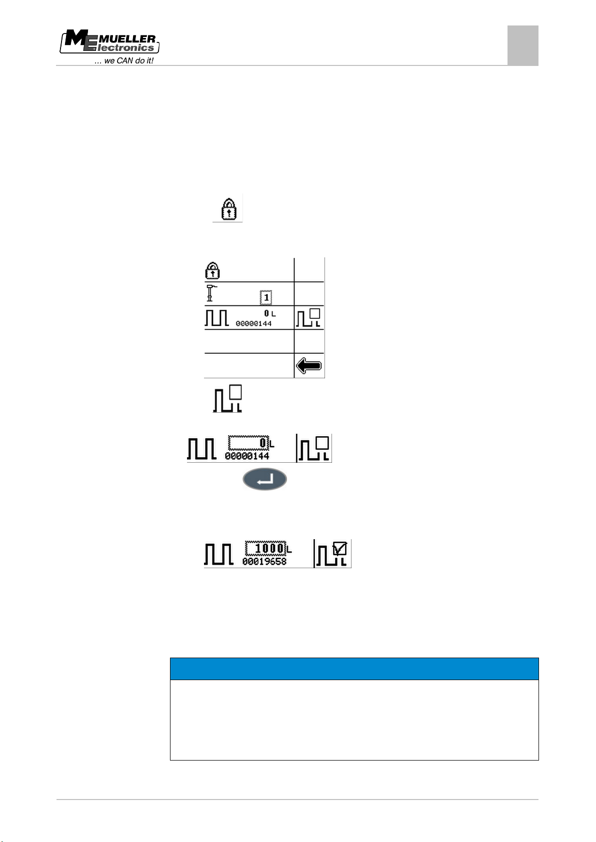
TANK-Control II uses a frequency signal to transmit fill levels. You can simulate a fill level in order to
test whether the frequency signal is being transmitted.
1. Open the "Sensors" menu.
2. Press:
3. Enter the password (14232314).
⇨ The following screen will appear:
4. Press:
5. Select:
6. Press this key:
⇨ The data input screen appears.
7. Enter the fill level that you want to simulate, in this case: 1000l
⇨ The frequency value changes:
⇨ You have successfully simulated a fill level.
Managing system settings
You can restore the pre-set system settings or save changes you have made in the system.
If you restore the pre-set system settings, you will lose all your own settings.
If you change the pre-set system settings, you will lose the manufacturer's settings.
Before restoring the system:
1. Open the "Tank Control II" menu.
Page 60
60
Copyright © Müller-Elektronik GmbH & Co.KG
Maintenance and technical data
12
Managing system settings
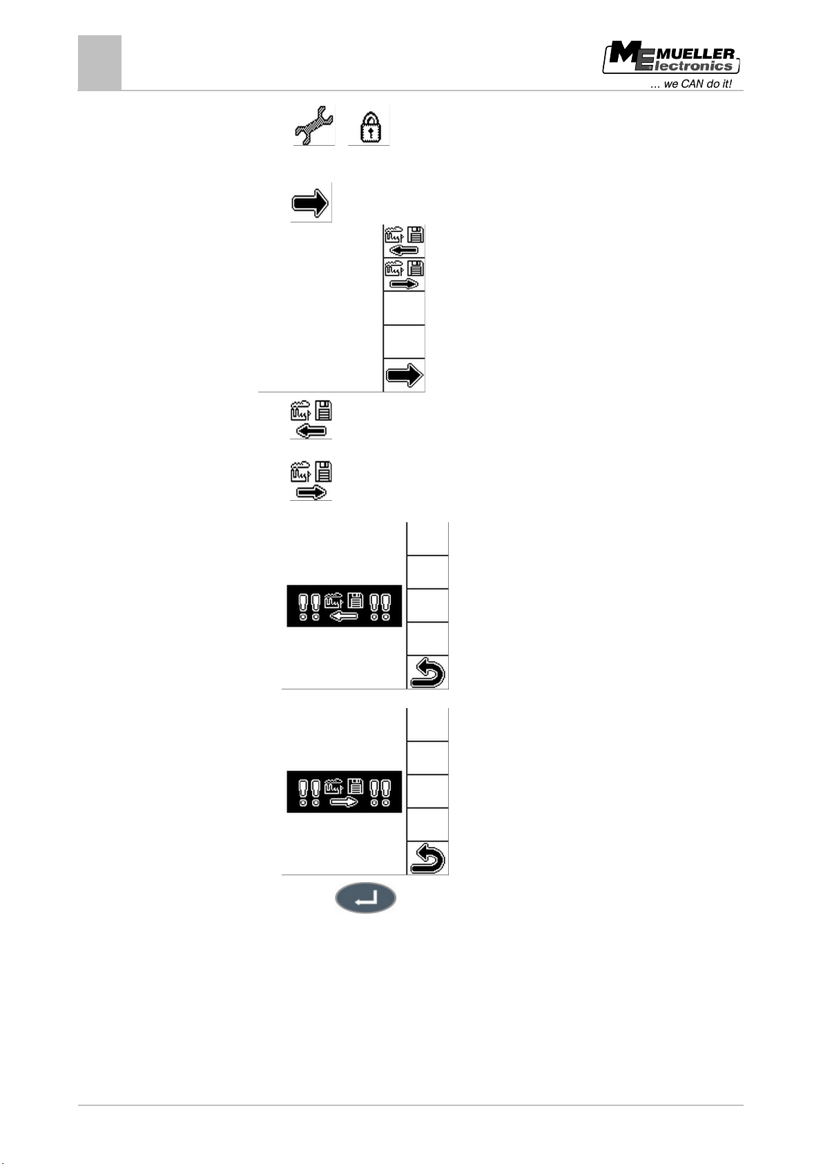
2. Press: >
3. Enter the password (14232314).
4. Press
until the following screen appears:
5. Press
to restore the system settings.
OR
Press
to save your changes in the system.
⇨ One of the following screens appears:
OR
6. Press this key:
⇨ You have restored the original system settings or saved new ones.
Page 61
Copyright © Müller-Elektronik GmbH & Co.KG
61
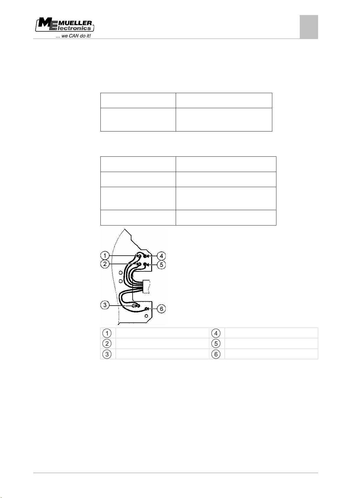
Input voltage
10.5V…16V
DIL switch on the printed circuit board)
Sensor tube
18 x 1.5
Tube material
Stainless steel 1.4571 DIN 17457
end
Length
From 32cm to 240cm (8cm in the mount)
green/yellow
white
12.3
Maintenance and technical data
Technical data
12
Technical data
CAN termination resistance 120 Ohm selectable (can be changed via
Mechanical specifications
Electrical specifications
Thread for attachment at lower
M12
black
grey
blue
brown
Page 62
62
Copyright © Müller-Elektronik GmbH & Co.KG
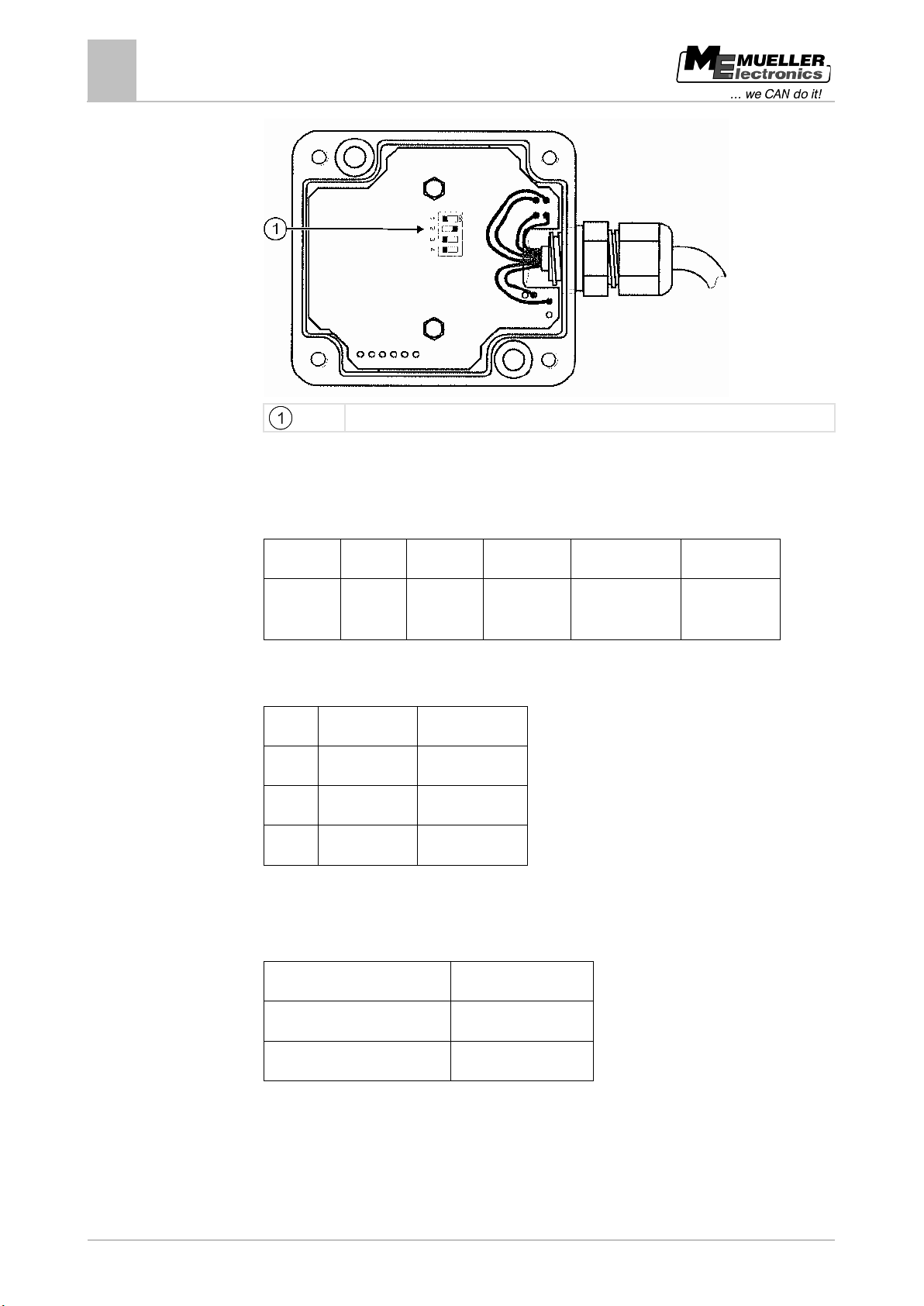
1 - brown
2 - grey
3 - blue
4 - white
5 - black
6 - green/yellow
in
Switch
OFF
ON
1
Sensor No. 1
Sensor No. 2
2
CAN open
CAN 120 Ohm
3 + 4
CAN stub
CAN loop
Operating temperature
-20°C…+70°C
Protection rating:
IP65
EMC testing
To DIN EN 14982
Maintenance and technical data
12
Technical data
DIL switch position
Connecting cable
Ölflex 100 6G0,5, 1m long with 6-pin Superseal pin contact connector
+12V Earth CAN High-
CAN Low-in CAN High-out CAN Low-out
Configuration
Switch 3 + 4 not used in this model.
Environmental conditions
Page 63
Copyright © Müller-Elektronik GmbH & Co.KG
63
Function
icon
Function
Function
icon
Function
22]
change page
48]
13
Appendix
13
Appendix
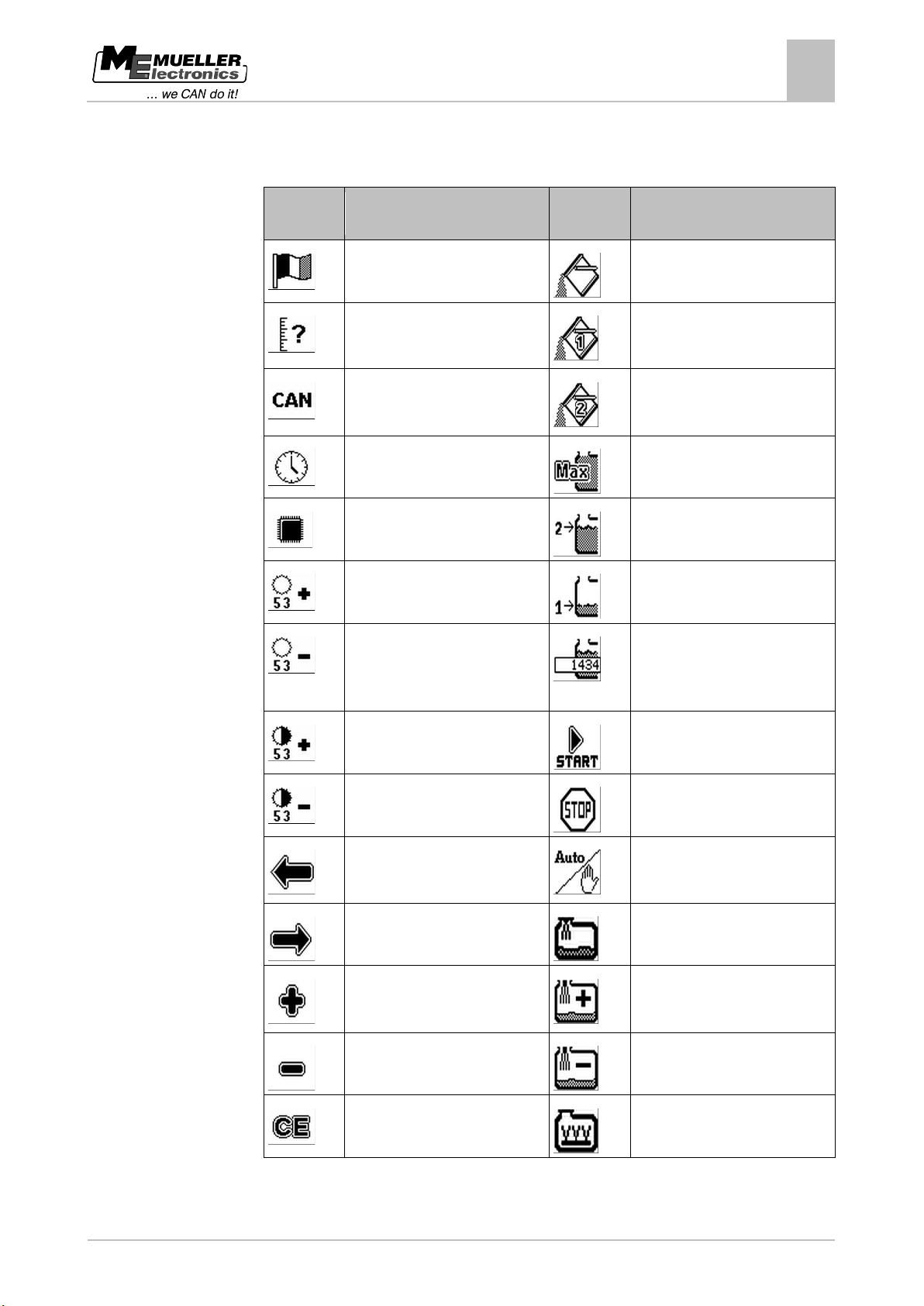
This section contains a list of all the function icons:
Set the language [➙ 21]
Set filling [➙ 38]
Set the system of measurement
[➙ 22]
Activate CAN communication [➙
Set filling for tank 1 [➙ 38]
Set filling for tank 2 [➙ 38]
Set the date and time [➙ 23]
Set maximum fill [➙ 41]
Display the voltage
Set filling up to fill limit 2 [➙ 41]
Increase screen brightness [➙ 24]
Set filling up to fill limit 1 [➙ 41]
Reduce screen brightness [➙ 24]
Increase screen contrast [➙ 24]
Reduce screen contrast [➙ 24]
Move to previous digit position or
change page
Move to next digit position or
Increase value
Reduce value
Set the part tank volume required
for the remaining area as a fill limit
[➙ 41]
Start filling [➙ 41]
Stop filling manually [➙ 41]
Change the mode of the external
devices [➙ 46]
Set the filling pump [➙ 48]
Increase filling pump speed [➙
Reduce filling pump speed [➙ 48]
Set all values to 0
Set agitator [➙ 50]
Page 64
64
Copyright © Müller-Elektronik GmbH & Co.KG
icon
icon
26]
27]
area
values
area
36]
36]
13
Appendix
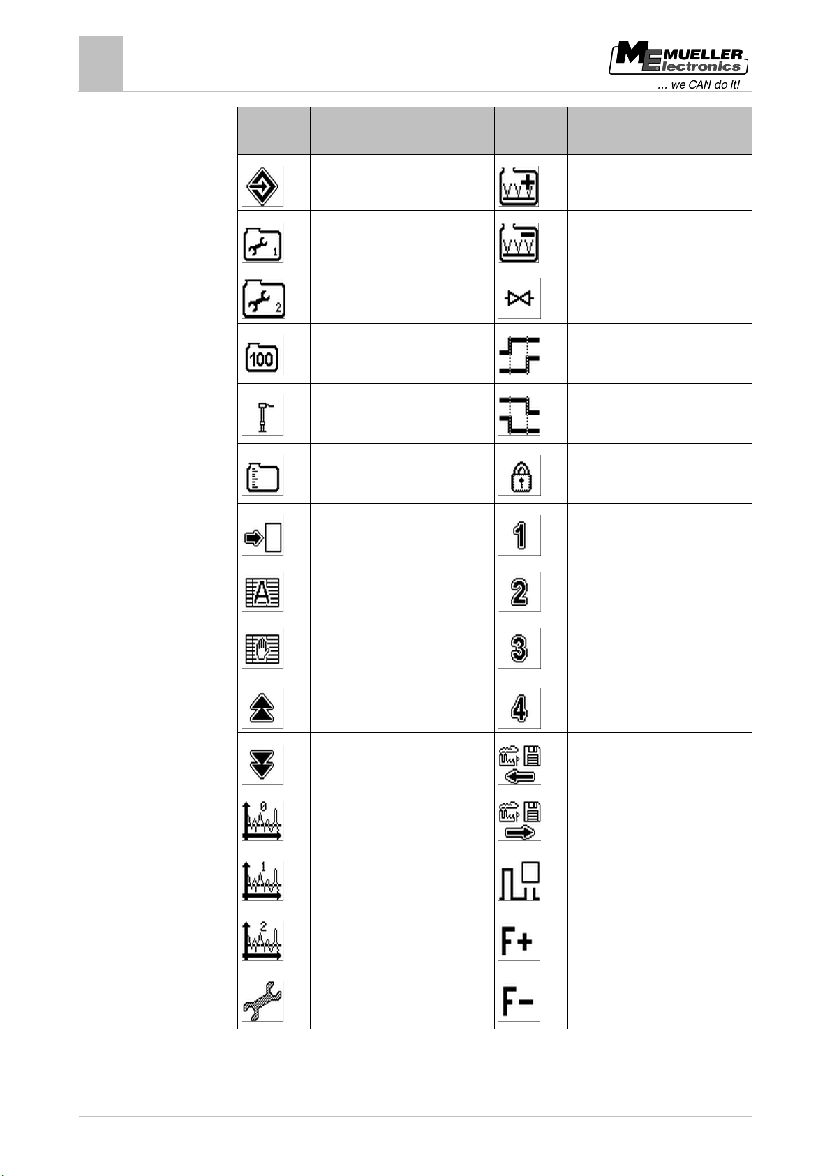
Function
Function Function
Save values
Calibrate sensor for tank 1 [➙ 25]
Calibrate sensor for tank 2 [➙ 25]
Carry out 100 litre calibration [➙
Carry out basic initialisation [➙
Calibrate tank or select tank type
[➙ 28]
Set sensor sensitivity [➙ 36]
Function
Increase agitator speed [➙ 50]
Reduce agitator speed [➙ 50]
Set ball valve [➙ 49]
Set ball valve start time [➙ 49]
Set ball valve stop time [➙ 49]
Open locked area
Enter a figure in the protected
area
Carry out automatic filling [➙ 31]
Enter calibration values manually
[➙ 35]
Scroll up through measured
Scroll down through measured
values
Set sensor sensitivity to high [➙
Set sensor sensitivity to normal
[➙ 36]
Set sensor sensitivity to low [➙
Enter a figure in the protected
Enter a figure in the protected
area
Enter a figure in the protected
Restore system settings [➙ 59]
Save new system settings [➙ 59]
Simulate the fill level [➙ 59]
Increase PWM frequency [➙ 55]
View configuration of external
Reduce PWM frequency [➙ 55]
devices [➙ 47]
 Loading...