

Page 1
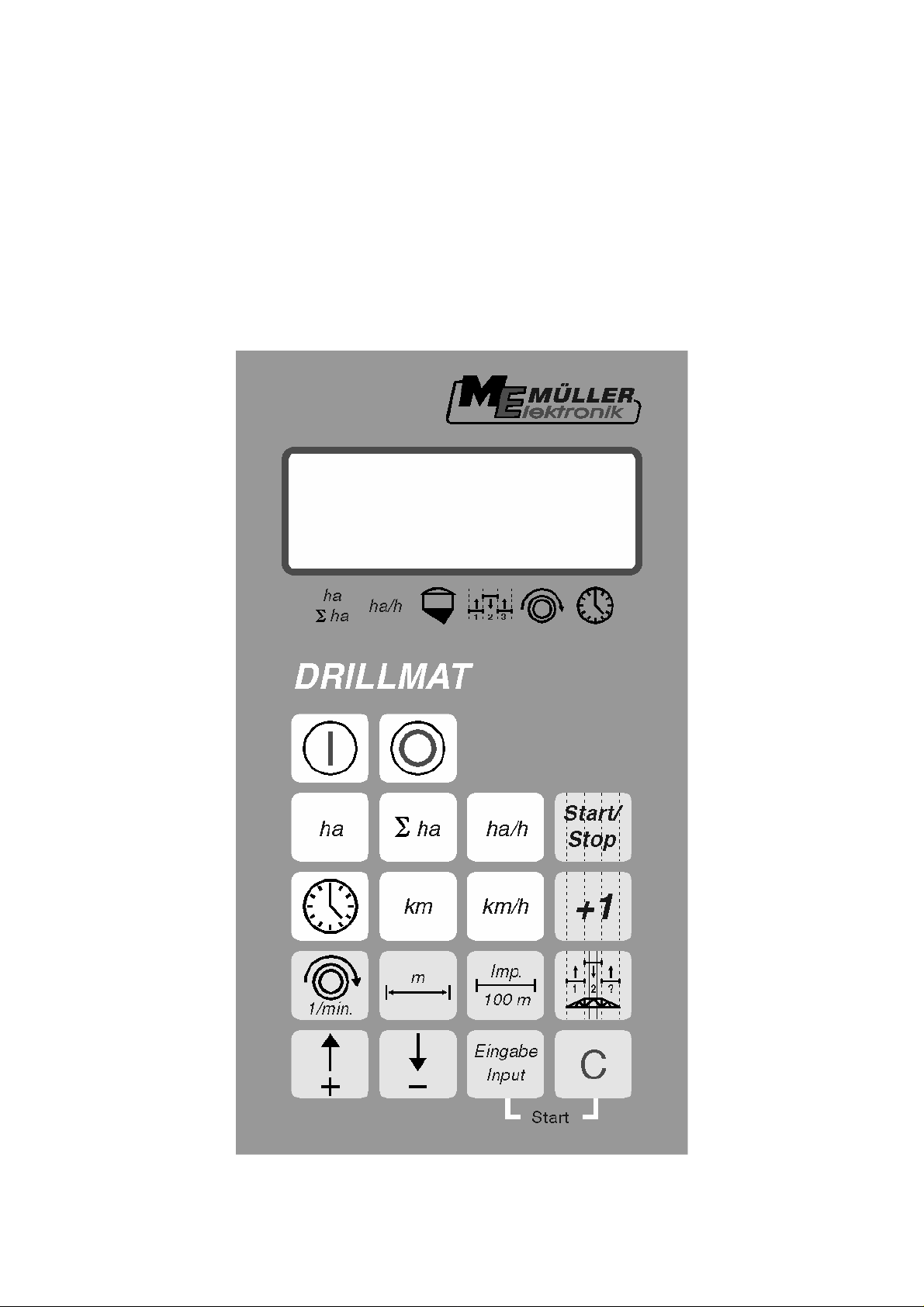
Installation and Operating Instructions
Drillmat
February 1999
-------------------------
Read carefully before initial operation !
File: 302836-02_E(ME019441) [03.12.2007]
Page 2

Contents
1 System description.................................................................................... 3
1.1 Machine distributor....................................................................................... 3
1.2 Computer..................................................................................................... 4
2 Installation instructions - Drillmat............................................................ 5
2.1 Computer..................................................................................................... 5
2.2 12V plug connection to the tractor battery.....................................................5
2.3 Signal distributor - machine.......................................................................... 5
2.4 Sensors........................................................................................................5
3 Safety.......................................................................................................... 7
3.1 Specified implementation............................................................................. 7
3.2 Safety instructions........................................................................................ 7
4 Operating instructions............................................................................... 8
4.1 Initial operation............................................................................................. 8
4.2 Description of the entry keys........................................................................8
4.2.1 Setting keys +/-............................................................................................ 8
4.2.2 "Working width" key ..................................................................................... 8
4.2.3 "Impulses/100m" key.................................................................................... 9
4.2.4 "RPM" key ".................................................................................................. 9
4.2.5 "Tram line rhythm" key............................................................................... 10
4.2.6 "+1" key...................................................................................................... 11
4.2.7 "Start/stop" key .......................................................................................... 11
4.3 Description of the function keys................................................................. 12
4.3.1 Device on/off.............................................................................................. 12
4.3.2 "Start function"........................................................................................... 12
4.3.3 "Time" key.................................................................................................. 12
4.3.4 "Area" key.................................................................................................. 12
4.3.5 "Total area" key.......................................................................................... 13
4.3.6 "Current area output" key...........................................................................13
4.3.7 "Distance" key............................................................................................ 13
4.3.8 "Speed" key ............................................................................................... 13
4.4 Operation process...................................................................................... 14
5 Maintenance............................................................................................. 14
5.1 Computer................................................................................................... 14
5.2 Sensors......................................................................................................14
6 Error recovery ........................................................................................ 15
6.1 The device does not switch on................................................................... 15
6.1.1 The computer displays HALP 00 or HALP 88 ............................................ 15
6.2 The speed is not displayed ........................................................................ 15
6.3 The area is not displayed........................................................................... 15
Page - 2 - Copyright Müller-Elektronik GmbH u. Co. Installation and Operating Instructions (02/99)
Page 3
333
r
1 System description
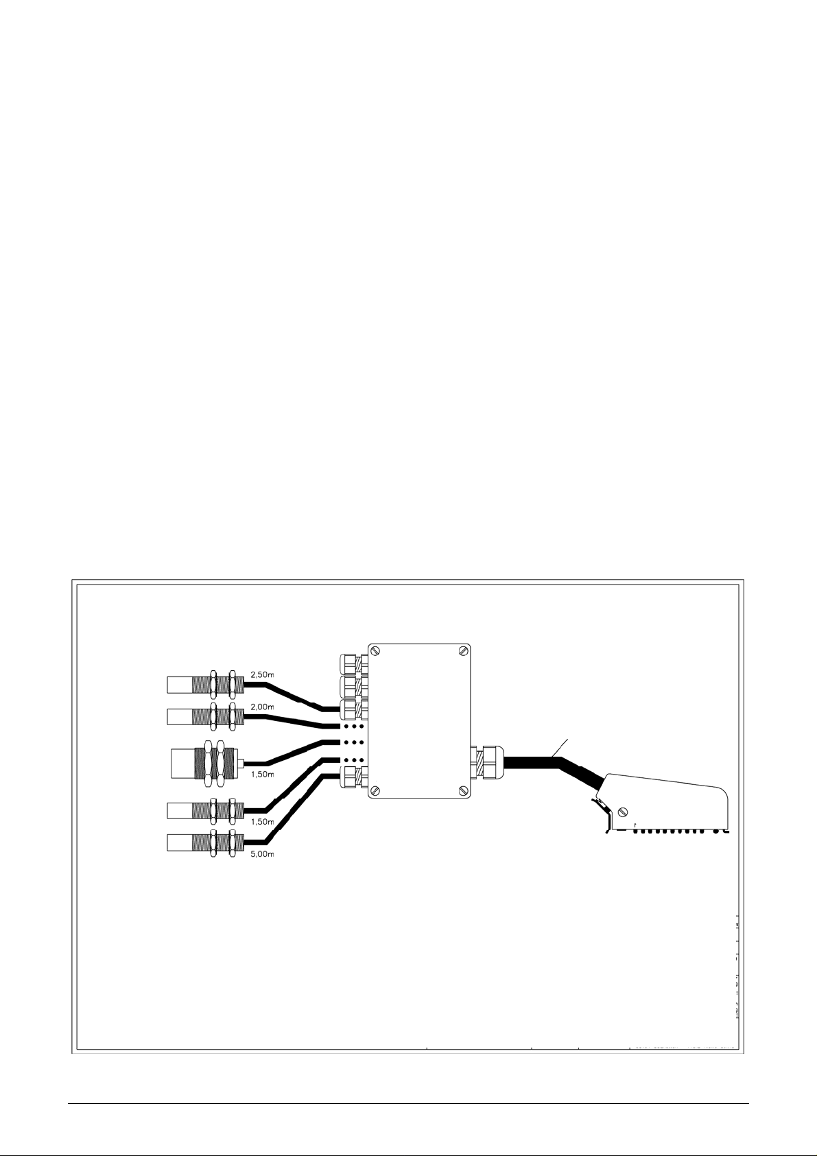
The Drillmat is used to monitor the seed drill, to establish the working data and for
tram line drilling.
The Drillmat essentially consists of:
- The board computer (installed in the cabin of the tractor) for the entry of the required
data as well as serving as a monitor. In the case of a fault, an acoustic and optical
alarm is set off.
- The machine distributor (installed on the frame of the Drillmat) with a connecting cable to the board computer.
With wheel sensor
Sensor for monitoring the drill shaft
Sensor for monitoring the fan
Level sensor
Track marker
1.1 Machine distributor
Tram line L
Hall element
Hall sensor Cable – 14x1.00qmm
Capacitive sensor
Reed contact
Reed contact
Tram line R
Wheel
Fan
Level
Drill shaft
Track marke
Lg – 6.50m
30pin multipoint plug
Copyright Müller-Elektronik GmbH u. Co. Installation and Operating Instructions Drillmat (02/99) Page - 3 -
Page 4
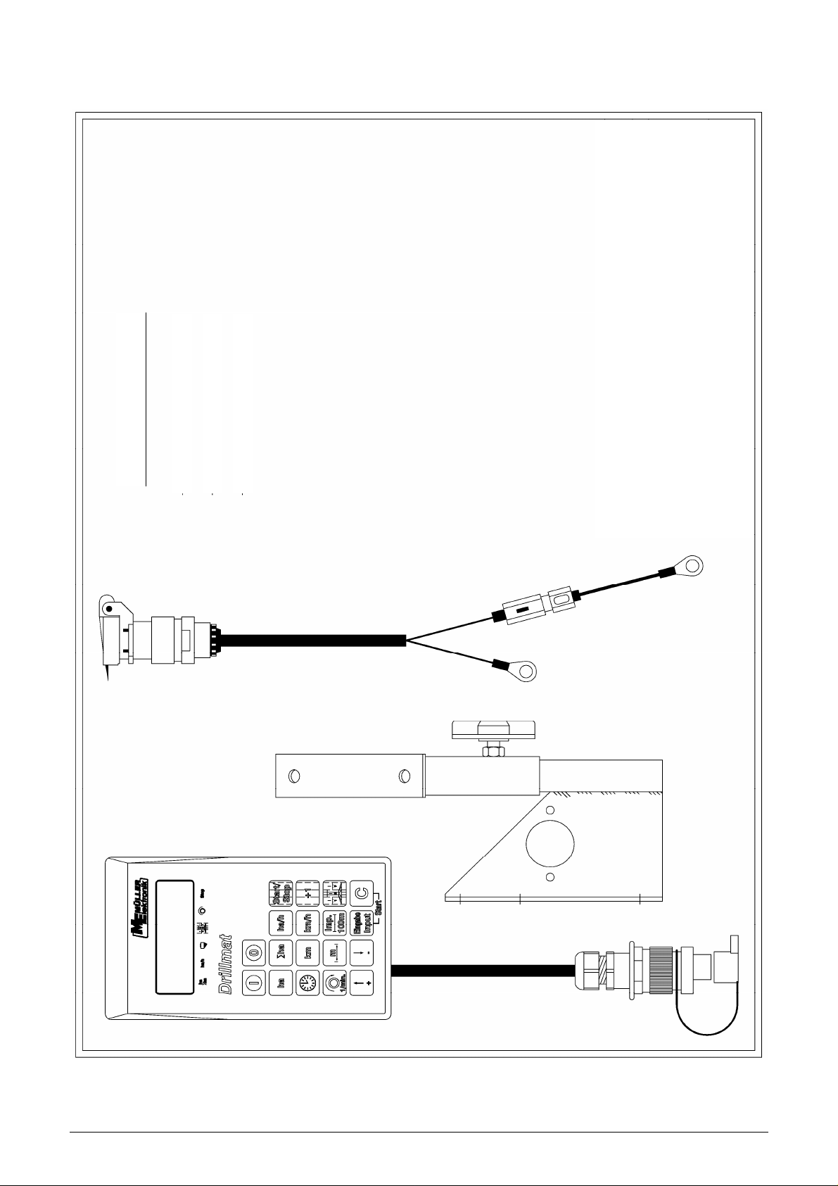
1.2 Computer
Delivery content
– ) Drillmat compter
– ) Battery cable
– ) Console
Page - 4 - Copyright Müller-Elektronik GmbH u. Co. Installation and Operating Instructions (02/99)
Page 5

2 Installation instructions – Drillmat
2.1 Computer
The computer is to be installed together with the console within the driver’s field of
visibility. The distance from the radio equipment or radio antenna should be at least
1 m.
2.2 12V socket connection to the tractor battery
For the Drillmat’s current supply (computer and sensors) the 12V socket supplied is
to be connected to the tractor battery. No second device should be connected to this
12V socket. The 12V socket must be protected by a 25A safety fuse, which is to be
found in the wire connector to the brown 12V wire.
Wire colours
brown = + 12 Volt
blue = ground
The battery’s negative pole must always be at ground (frame, chassis).
2.3 Signal distributor machine
The signal distributor and the sensors are factory installed
2.4 Sensors
- Wheel sensor (Hall element)
With the wheel sensor the device determines the distance covered as well as the
area.
The tube clip and magnet are mounted on to the wheel. The red side must point towards the sensor. The sensor is to be mounted to the fixture provided at a distance
of 5-10 mm. A terminal block is provided for each lead in the machine distributor.
Copyright Müller-Elektronik GmbH u. Co. Installation and Operating Instructions Drillmat (02/99) Page - 5 -
Page 6

- Drill shaft sensor (Reed contact)
This sensor monitors the function of the drill shaft.
The tube clip and magnet are mounted on to the drill shaft. The red side must point
towards the sensor. The sensor must be mounted to the fixture provided at a distance of approximately 20 mm.
- Level sensor (capacitive)
The sensor controls the seed bin.
As soon as the surface is no longer covered with grain, the sensor switches on and
the computer sends out an alarm.
The sensor should be placed in the seed bin, so that it switches on as soon as the
set amount of residue is reached. The end of the sensor should protrude 20 mm
from the screw fitting.
The sensitivity can be regulated at the back of the sensor. When the sensor switches
on, the lamp on the sensor lights up.
- Track marker (Reed contact)
The sensor indicates to the computer that the track markers have switched.
The sensor is to be mounted on to a static fixture opposite the switch mechanism for
the track marker. The magnet is to be mounted on to the switch mechanism opposite
the sensor at a distance of 20 mm. The magnet must momentarily be lead past the
sensor when the track indicator switches. It’s end position should not be in front of
the sensor.
The tram line meter moves on one position each time the track marker switches on.
- Seed drill without track marker
The switch impulse is picked up when the top link is raised. The magnet and sensor
should be mounted so that they approach each other in a raised position at roughly
20 mm.
In a working position the distance must be at least 40 mm.
- Fan sensor (Hall element)
Rpm monitor on the fan
Both magnets are to be mounted to the fixture provided. The red side must point towards the sensor. The sensor must be mounted at a distance of 5-10 mm to the sensors
Page - 6 - Copyright Müller-Elektronik GmbH u. Co. Installation and Operating Instructions (02/99)
Page 7

3 Safety
3.1 Specified implementation
The Drillmat is specified exclusively for use in agriculture. Any application outwith
this area is regarded as unspecified.
The manufacturer does not accept liability for damage to persons or property resulting from unspecified use. In such cases all risks are the responsibility of the user.
Specified implementation also includes adhering to the operation and maintenance
conditions stipulated by the manufacturer in the operating instructions.
Relevant accident prevention regulations as well as other generally recognized
safety, industrial-medical and road traffic rules are to be adhered to. In addition the
manufacturer accepts no liability in cases where arbitrary modifications have been
made to the Drillmat.
3.2 Safety instructions
Before working on the electrical system or carrying out any welding operations on
the tractor or on an attached implement, the battery connection must be interrupted.
Copyright Müller-Elektronik GmbH u. Co. Installation and Operating Instructions Drillmat (02/99) Page - 7 -
Page 8
4 Operating instructions
4.1 Initial operation
The device carries out a self-test when switched on. After completion the function
last used before switch-off is automatically selected.
In the case of an electronical fault the device displays:
HALP 00 or HALP 88
In this case return the device for repair.
4.2 Description of the entry keys
The keyboard has two colours:
White keys = function keys (display the recorded data)
Grey keys = entry keys (enter the machine data) and control keys
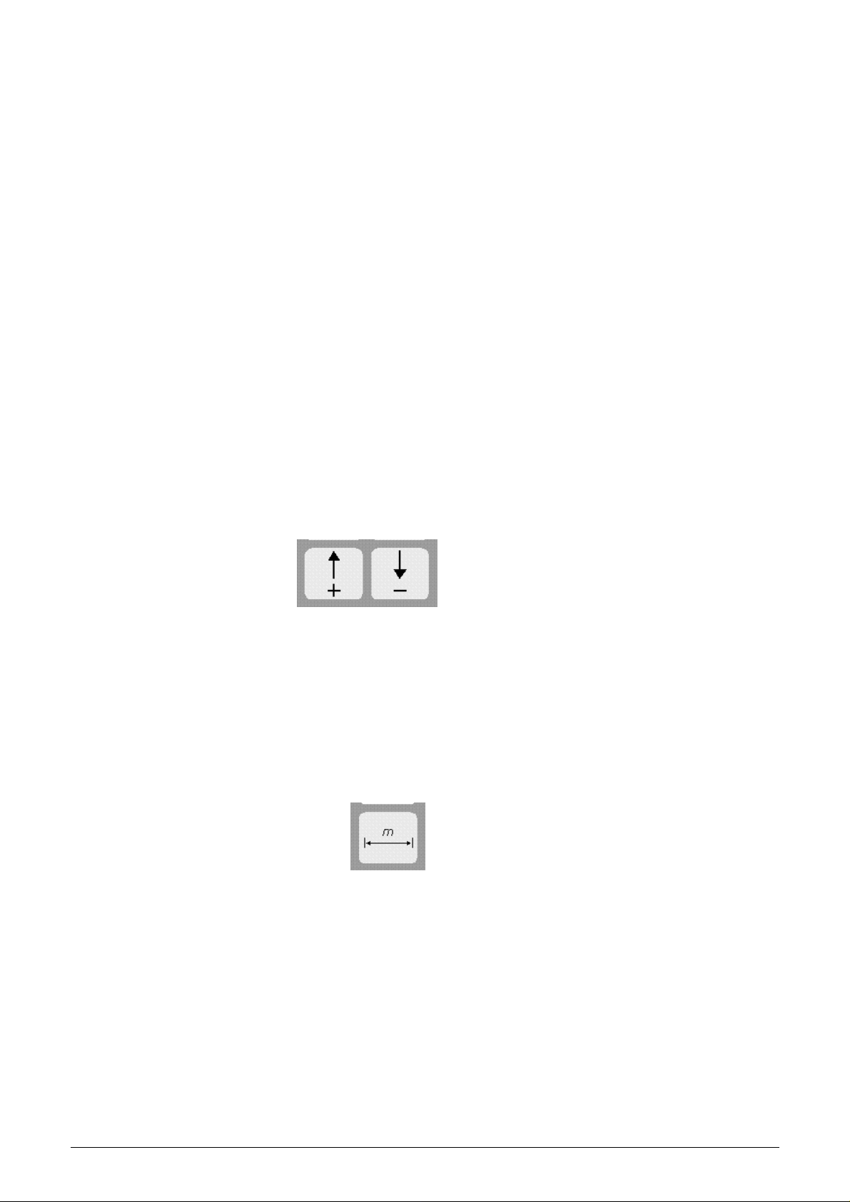
4.2.1 Setting keys +/-
When the + or – key is first pressed the display moves one poition in the required direction.
Each time the key is pressed again, the display moves on until the key is let loose.
The board computer requires following machine data in order to be able to operate
at all: Impulses/100m, working width, drill shaft rpm and the tram line rhythm.
4.2.2 " Working width " key
This key is used to enter the actual working width
- Press " working width" key
- Select value using the +/- keys
- Press "enter" (=) key
Finally the value entered should be controlled once more by pressing the " working
width" key.
Page - 8 - Copyright Müller-Elektronik GmbH u. Co. Installation and Operating Instructions (02/99)
Page 9
4.2.3 " Impulses/100 m" key
With this key the number of impulses recorded to the computer by the wheel sensor
during a journey of 100 m are entered.
There are two possibilities to enter the data:
1. The impulses/100m value is known
- Press "impulses/100m" key
- Select value using the +/- keys
- Press "enter" (=) key.
2. The impulses/100m value is not known
- Measure out and mark a distance of 100 m on the field
- Bring vehicle to the start position
- Press "impulses/100m" and " C " key simultaneously
- Travel a distance of 100 m
- Press "enter" (=) key
4.2.4 "RPM" key
With the initial operation the rated rpm must be communicated to the computer.
The entry is to be carried out as follows:
- Start up the machine
- Press the "rpm" key
(current rpm will be displayed).
- Press "enter" (=) key
The value displayed at this moment in time is saved as the rated rpm
If monitoring is to be switched off, the following entry is required:
- Press the "rpm" key (display 0)
- Press "enter" (=) key
- Rpm monitoring is so switched off
The rpm alarm is displayed by a hooting sound and a flashing of the arrow above the
rpm display every second. This occurs every 5 seconds with the drill shaft alarm.
Copyright Müller-Elektronik GmbH u. Co. Installation and Operating Instructions Drillmat (02/99) Page - 9 -
Page 10
4.2.5 "Tram line rhythm" key
Tram lines can be laid out automatically using the Drillmat. For this purpose, the corresponding shares must be closed. The working width of the seed drill and the cultivator have to be taken into account. The tram line rhythm can be calculated from
these values.
Working width of the cultivator
Tram line rhythm = --------------------------------------------- Working width of the seed drill
Example: You are using a field sprayer with a working width of 24 m and a seed drill
with a working width of 6 m. In this case the tram line rhythm is 24m : 6m = 4.
The calculation results in even (2, 4, 6 etc.) and uneven (1, 3, 5 etc.) rhythms. In the
case of even rhythms, the tram lines are usually laid out in 2 runs. As this tends to
be more inaccurate, the even rhythms can be laid out in one run (S rhythms, e.g. 4S;
6S etc.) However, it has to be taken into consideration that the first run is carried out
with half the working width of the seed drill and subsequently begins with position 1
of the rhythm.
Following rhythms are supported by the Drillmat:
No. Rhythm Tram line No. Rhythm Tram line
0 No rhythm 0 2-S 2s 1
2 2 1, 2 4-S 4s 2
3 3 2 6-S 6s 3
4 4 2, 3 8-S 8s 4
5 5 3 10-S 10s 5
6 6 3, 4 12-S 12s 6
7 7 4
8 8 4, 5
9 9 5
10 10 5, 6
11 11 6
12 12 6, 7
14 14 7, 8
Tram line
left
15 10 (20m/8m, 15/6m) be-
2; 9 4; 7
Tram line
right
ginning on the right
16 10 (20m/8m, 15/6m) be-
4; 7 2; 9
ginning on the left
18 18 (18m/4m, 27/6m) be-
3; 16 7; 12
ginning on the left
19 10 (18m/4m, 27/6m)
7; 12 3; 16
beginning on the right
Page - 10 - Copyright Müller-Elektronik GmbH u. Co. Installation and Operating Instructions (02/99)
Page 11
To adjust the tram line rhythm press the tram line rhythm key. The correct rhythm is
then set with the +/- setting keys. Finally the new rhythm is confirmed with the enter
key.
If the correct tram line rhythm has been adjusted and set to 1, the side of the field
where work is to begin still has to be taken into account. With uneven and S
rhythms, work can begin on either side of the field. With the even rhythms 4, 8 and
12, work must begin at the side where the closed share is, and with rhythms 6, 10
and 14 on the opposite side of the field.
In the case of the special rhythms, no. 15, 16, 18, 19 the side of the field where work
is to begin must be determined first. “Beginning on the left” means that the side of
the field when starting lies on the left hand side of the tractor in the direction of
travel. Consequently, “beginning on the left” is the other way round.
4.2.6 "+1" key
With this key the tram lines can be switched on further manually by one step at a
time.
4.2.7 "Start/Stop" key
With this key the automatic relaying of the tram line rhythm can be stopped and released again.
When stopped, the arrow above the tram line symbol flashes !
Copyright Müller-Elektronik GmbH u. Co. Installation and Operating Instructions Drillmat (02/99) Page - 11 -
Page 12
4.3 Description of the function keys
4.3.1 Device on/off
The device is switched on by pressing the On (I) key.
Switch off with the Off (0) key.
Should the voltage supply drop to below 9 volt, e.g. when starting the tractor, the
computer switches off automatically. It can be switched on again by pressing the On
key.
4.3.2 "Start function"
The start function is released by pressing the "=" and "C" keys simultaneously. That
means that the memory for the area, time and distance is set to 0. The time is restarted automatically by pressing this key. This function is to be carried out at the
beginning of each operation.
4.3.3 "Time" key
The operating time since carrying out the “start function” (see 4.3.2) is displayed by
pressing this key. If the tractor is switched off and the computer voltage-free, the
time data entry is stopped. It restarts once the device is switched on again. The
clock can also be stopped during operation. After the “time” key has been pressed, it
can be pressed once again to stop the clock. To restart it, the “time” key has to be
pressed yet again.
4.3.4 "Area" key
The area covered since carrying out the “start function” (see 4.3.2) is displayed by
pressing this key. Measurement is interrupted as soon as the computer stops receiving wheel impulses.
Page - 12 - Copyright Müller-Elektronik GmbH u. Co. Installation and Operating Instructions (02/99)
Page 13
4.3.5 "Total area" key
With this key the total area for a whole season can be determined. The memory is
set to 0 at the beginning of the season by pressing the “total area” and “C” keys simultaneously.
4.3.6 "Current area output" key
With this key the current area output is displayed in ha/h.
4.3.7 "Distance" key
The distance covered since carrying out the “start function” (see 4.3.2) is displayed
by pressing this key.
4.3.8 "Speed"
When this key is pressed the current speed travelled is displayed.
Copyright Müller-Elektronik GmbH u. Co. Installation and Operating Instructions Drillmat (02/99) Page - 13 -
Page 14

4.4 Operation process
Once the machine data have been entered, the following steps have to be carried
out before beginning operation. The track marker at the beginning of the field is to be
operated so that the right side is lowered.
Subsequently only the start function has to be carried out (see 4.3.2).
After that, each time the end of the field is reached and the track marker switched,
tram line drilling is continued automatically. Even when the computer is switched off
temporarily, the last position is stored. When the computer is switched on again, the
last setting is available once more. Drilling can begin again immediately.
During the operation process the area, total area, operating time, distance are determined and the speed and output displayed.
5 Maintenance
5.1 Computer
The computer is maintenance-free. During the winter it should be stored at room
temperature.
5.2 Sensors
The sensors are maintenance-free
Page - 14 - Copyright Müller-Elektronik GmbH u. Co. Installation and Operating Instructions (02/99)
Page 15
6 Error recovery
When trouble shooting keep to the intended sequence!
Error Cause Measures
6.1 The device does not switch on
6.1.1 The computer dis-
Polarity reversal of the voltage supply
Voltage supply interrupted Check battery connection
Total failure Send in device
Memory error Send in device
Check polarity
cable; control battery clamps
and fuse
plays
HALP 00 or
HALP 88
6.2 Speed is not displayed
Impulses/100m not entered Enter number of Im-
pulses/100m (see 4.2.3.)
The wheel sensor is not
sending any impulses to the
computer, the ring in the
display is not flashing during
the journey.
Sensor is defective, replace
Computer is defective, re-
Adjust the distance of the
wheel sensor to the magnet
to 5-10mm.
The red side of the magnet
must point towards the sensor.
Secure magnet with a nonmagnetic screw.
Connect cable in the distributor correctly
green = gn = signal
brown = br = + 12 volts
white = ws = 0 volt
place
6.3 The area is not displayed
Copyright Müller-Elektronik GmbH u. Co. Installation and Operating Instructions Drillmat (02/99) Page - 15 -
Distributor is defective, re-
place
Working width not entered Enter working width
(see 4.2.2.)
 Loading...