

Page 1
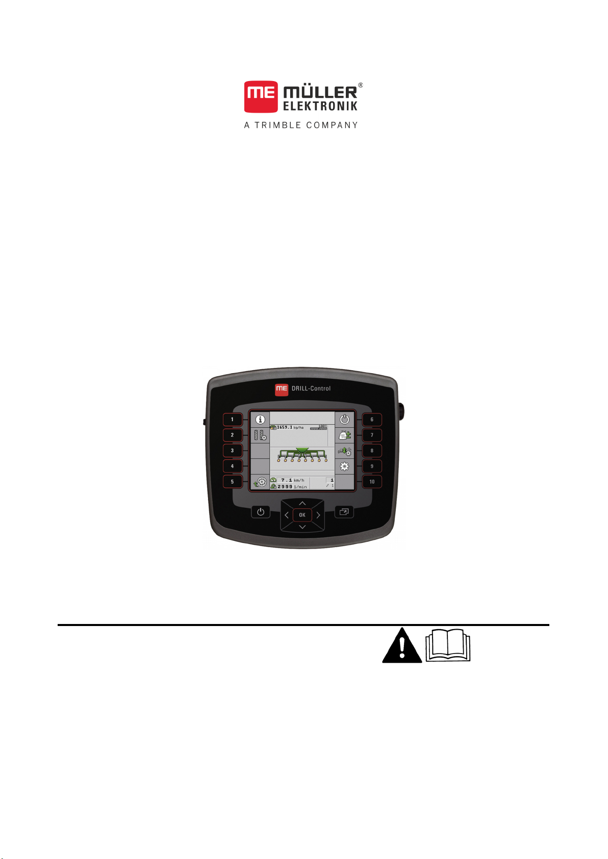
Installation and operating instructions
DRILL-Control
Version: V2.20191001
30283620-02-EN Read and follow these instructions. Keep these instructions in a
safe place for later reference. Please note that there might be a
more recent version of these instructions on the homepage.
Page 2

Document
Copyright ©
Company details
Installation and operating instructions
Product: DRILL-Control
Document number: 30283620-02-EN
As of software version: 0.0.17.0
Original instructions
Original language: German
Müller-Elektronik GmbH
Franz-Kleine-Straße 18
33154 Salzkotten
Germany
Phone: ++49 (0) 5258 / 9834 - 0
Fax: ++49 (0) 5258 / 9834 - 90
Email: [email protected]
Homepage: http://www.mueller-elektronik.de
Page 3
30283620-02-EN
V2.20191001
3
1
For your safety
6
1.1
Basic safety instructions
6
1.2
Intended use
6
1.3
Layout and meaning of warnings
6
1.4
Disposal
7
2
About the on-board integrated display/controller
8
2.1
Functions of the on-board integrated display/controller
8
2.2
System overview
8
2.3
Overview of keys
9
2.4
Information on the rating plate
10
3
About these Operating Instructions
11
3.1
Who is the target user for these Operating Instructions?
11
3.2
Scope of the instructions
11
3.3
Directional information in these instructions
11
3.4
Layout of operating instructions
11
3.5
Layout of references
12
4
Mounting and installation
13
4.1
Installing the on-board integrated display/controller
13
4.2
Installing the sensors on the implement
13
4.2.1
Installing the revolution sensors
14
4.2.2
Installing the fill level sensor
15
4.2.3
Installing the working position sensors
16
4.2.4
Installing the speed sensor
17
5
Basic control principles
18
5.1
Switching on the on-board integrated display/controller
18
5.2
Layout of the work screen
18
6
Configuring the basic settings of the on-board integrated display/controller
20
6.1
Setting the date / time
20
6.2
Setting the brightness
20
6.3
Selecting the language
20
7
Operating the implement on the field
22
7.1
Setting target rate
22
7.2
Performing a calibration
22
7.3
Filling metering cells with seed
23
7.4
Start seeding
23
7.5
Stop seeding
24
Contents
Contents
Page 4

4
V2.20191001
30283620-02-EN
7.6
Adjusting the target rate during operation
24
7.7
Using tramline control
24
7.7.1
Configuring the tramline control
26
7.7.2
Determining the machine type
26
7.7.3
Selecting tramline rhythm
27
Creating an even tramline rhythm
28
Creating uneven tramline rhythms
31
Creating special tramline rhythms
32
7.7.4
Programming individual tramline rhythms
35
7.8
Operating the hydraulic system with the job computer
35
7.8.1
Operating bout markers
36
7.8.2
Using the waterhole mode
37
7.9
Viewing results
37
7.9.1
Results
37
7.9.2
Total results
38
8
Configuring the on-board integrated display/controller for work
39
8.1
Selecting and configuring the speed source
39
8.1.1
Calibrating the speed sensor with the 100m method
39
8.1.2
Entering the simulated speed
40
8.2
Associating products with a hopper
40
9
Configuring the implement equipment
41
9.1
General information on the configuration
41
9.1.1
Performing the configuration
41
9.1.2
Layout of the configuration screen
41
9.1.3
Configuration sequence
42
9.1.4
Configuration of individual implement parts
42
9.2
Configuration of the implement
43
9.2.1
“Number of Rows” parameter
43
9.2.2
“Tramline System” parameter
43
9.2.3
"Bout marker" parameter
43
9.2.4
“Waterhole Mode” parameter
43
9.3
Configuration of the hoppers
43
9.3.1
“Upper Level Sensor” parameter
43
9.3.2
“Lower Level Sensor” parameter
43
9.4
Configuration of the metering units
43
9.4.1
“Gear Ratio” parameter
44
9.4.2
“Pre-start Time” parameter
44
9.4.3
“Early Stop Time“ parameter
44
9.5
Configuration of the rows
44
9.5.1
“Assigned Tramline” parameter
44
9.6
Configuration of the sections
44
9.6.1
"Working Width" parameter
45
10
Using the system functions of the on-board integrated display/controller
46
10.1
Creating screenshots
46
10.2
Exporting a configuration
46
Contents
Page 5
30283620-02-EN
V2.20191001
5
10.3
Importing a configuration
46
10.4
Updating the on-board integrated display/controller
47
11
Troubleshooting
48
11.1
Performing diagnostics
48
11.2
Checking the version numbers
50
11.3
Alarm messages
50
12
Technical specifications
53
12.1
Technical specifications of the on-board integrated display/controller
53
12.2
Connector pin assignment
54
12.2.1
8-pin flange socket
54
12.2.2
39-pin multipole connector
54
12.3
Hydraulic system of the implement
55
13
Explanation of the signals in the pin-out diagram
56
14
Notes
58
Contents
Page 6
6
V2.20191001
30283620-02-EN
WARNING
physical injury, if not avoided.
CAUTION
This signal word identifies low-risk hazards, which could potentially cause minor or moderate
physical injury or damage to property, if not avoided.
1
1.1
1.2
1.3
For your safety
1
Basic safety instructions
For your safety
Please read the following safety instructions carefully before using the product for the first time.
▪ Read the operating instructions to the agricultural device which you want to control by using the
product.
▪ Do not make any unauthorized modifications to the product. Unauthorized modifications or use
may impair safety and reduce the service life or operability of the unit. Modifications are
considered unauthorized if they are not described in the product documentation.
▪ Never remove any safety mechanisms or stickers from the product.
▪ The product does not include any user serviceable parts. Do not open the casing.
▪ Before you leave the vehicle cab, ensure that all automatic mechanisms are deactivated or
manual mode is activated.
▪ Before charging the tractor battery, always disconnect the tractor from the job computer.
▪ Keep children away from the implement and from the job computer.
Intended use
The job computer is intended exclusively for use in agriculture. The manufacturer cannot be held
responsible for any installation or use of the job computer that deviates from or exceeds the scope of
intended use.
The manufacturer cannot be held liable for any personal injury or property damage resulting from
such non-compliance. All risk arising from improper use lies with the user.
Basic safety instructions
Intended use also includes compliance with the conditions for operation and repairs prescribed by the
manufacturer.
All applicable accident prevention regulations and all other generally recognized safety, industrial,
and medical standards as well as all road traffic laws must be observed. Any unauthorized
modifications made to the equipment will void the manufacturer's warranty.
Layout and meaning of warnings
All safety instructions found in these Operating Instructions are composed in accordance with the
following pattern:
This signal word identifies medium-risk hazards, which could potentially cause death or serious
Page 7
30283620-02-EN
V2.20191001
7
NOTICE
This signal word identifies actions which could lead to operational malfunctions if performed
optimum work results.
Example
1.4
For your safety
Disposal
1
incorrectly.
These actions require that you operate in a precise and cautious manner in order to produce
There are some actions that need to be performed in several steps. If there is a risk involved in
carrying out any of these steps, a safety warning appears in the instructions themselves.
Safety instructions always directly precede the step involving risk and can be identified by their bold
font type and a signal word.
1. NOTICE! This is a notice. It warns that there is a risk involved in the next step.
2. Step involving risk.
Disposal
When it has reached the end of its service life, please dispose of this product as
electronic scrap in accordance with all applicable waste management laws.
Page 8
8
V2.20191001
30283620-02-EN
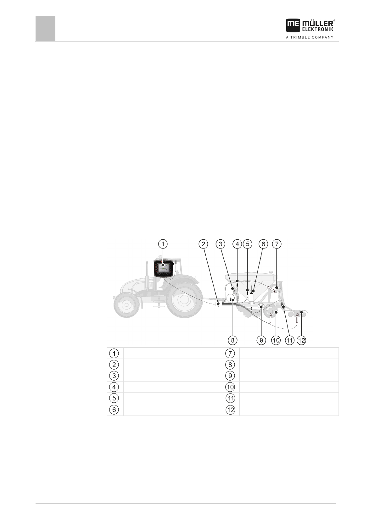
Cable harness
Revolution sensor
2
2.1
2.2
About the on-board integrated display/controller
2
Functions of the on-board integrated display/controller
About the on-board integrated display/controller
Functions of the on-board integrated display/controller
DRILL-Control is an on-board integrated display/controller.
A job computer is built into the on-board integrated display/controller, which can control the work of
seeders. When a job computer is mentioned within these instructions, it always refers to the DRILLControl on-board integrated display/controller.
Among other things, the on-board integrated display/controller can perform the following tasks:
▪ Monitoring of the metering shaft
▪ Control of the bout marker
▪ Control of the tramline valves
▪ Starting the calibration using the calibration button
▪ Control of the half width shutoff system
▪ Control of the pre-emergence marker
▪ Monitoring of the fan speed
System overview
The following diagram shows an example of how an implement can be structured:
DRILL-Control
Calibration button
Fill level sensor
Fill level sensor
Tramline valve
Radar sensor
Bout marker
Work position sensor
Electrical metering drive
Pre-emergence marker
Page 9
30283620-02-EN
V2.20191001
9
Keys
Function
display/controller on and off.
...
2.3
About the on-board integrated display/controller
Overview of keys
2
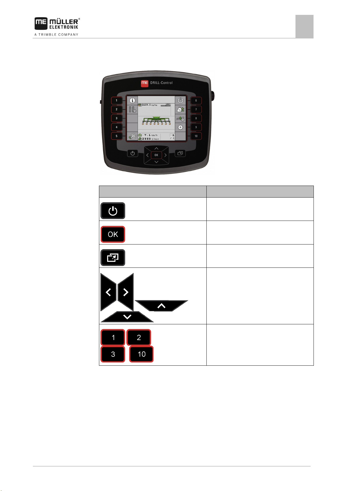
Overview of keys
DRILL-Control on-board integrated display/controller
Switches the on-board integrated
Confirms entries.
Creates screenshots.
Navigate within individual screens.
Performs the function shown on the screen.
Page 10
10
V2.20191001
30283620-02-EN
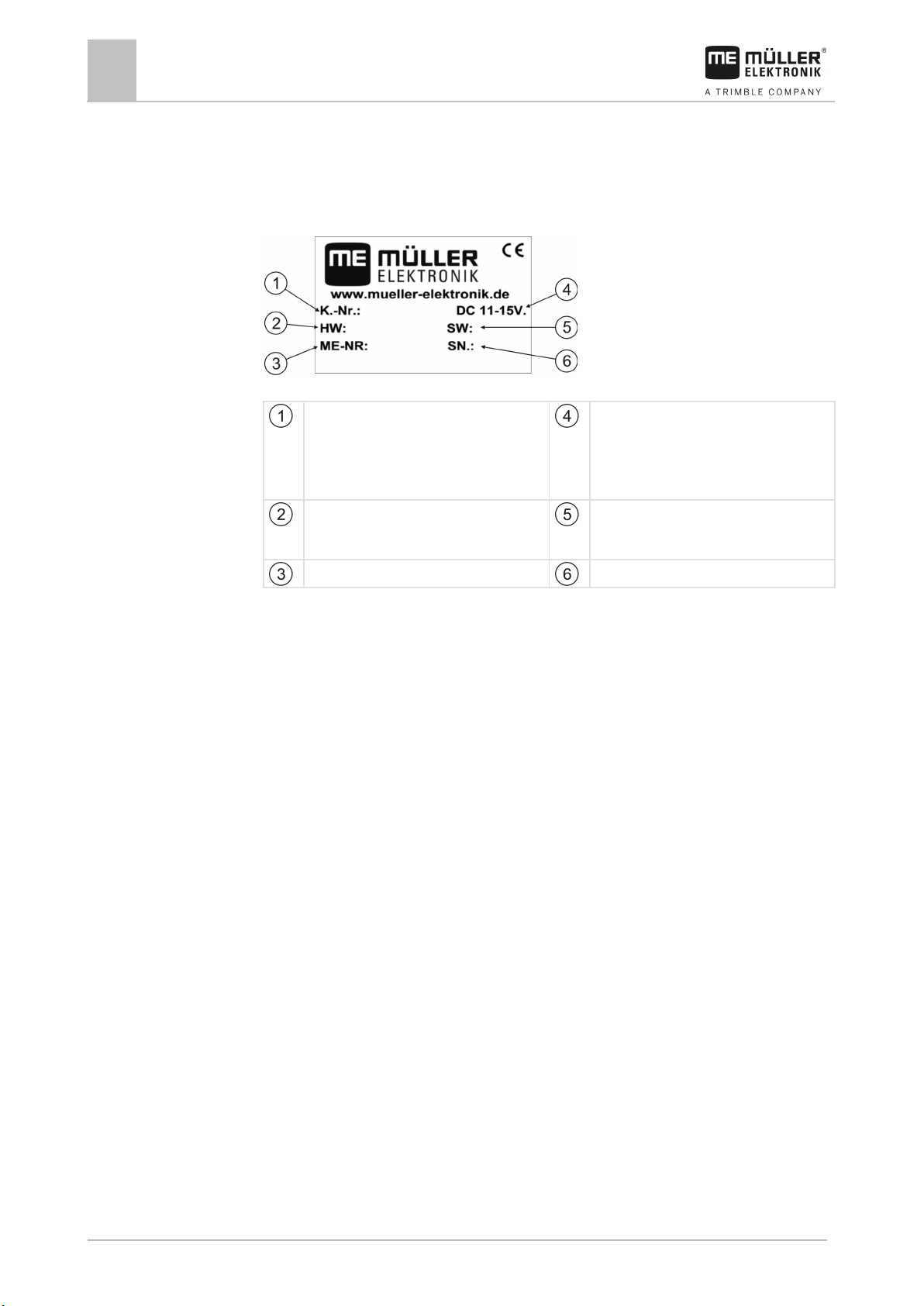
number will be shown here.
longer be up-to-date.
2.4
About the on-board integrated display/controller
2
Information on the rating plate
Information on the rating plate
A rating plate can be found on the casing of the on-board integrated display/controller. The rating
plate clearly identifies the on-board integrated display/controller.
Information on the rating plate
Client’s item number
If the product was manufactured for an
agricultural machinery manufacturer, the
agricultural machinery manufacturer's item
Operating voltage
The product may only be connected to
voltages within this range.
Hardware version
Müller-Elektronik item number
Software version at the time of delivery.
If you update the software, this version will no
Serial number
Page 11
30283620-02-EN
V2.20191001
11
Type of depiction
Meaning
2.
⇨
This will happen when you perform an action.
⇨
steps.
can be performed.
3
3.1
3.2
3.3
3.4
About these Operating Instructions
About these Operating Instructions
Who is the target user for these Operating Instructions?
3
Who is the target user for these Operating Instructions?
These Operating Instructions are intended for operators of seeders equipped with the DRILL-Control
on-board integrated display/controller manufactured by Müller-Elektronik.
Scope of the instructions
These instructions describe all of the functions that can be actuated with the on-board integrated
display/controller. This means that some chapters may not be relevant for the operation of certain
implements.
Directional information in these instructions
All directional information in these instructions, such as “left”, “right”, “forward”, “back”, is relative to
the movement direction of the vehicle.
Layout of operating instructions
The operating instructions explain step by step how you can perform certain operations with the
product.
We use the following symbols throughout these Operating Instructions to identify different operating
instructions:
1.
Actions that must be performed in succession.
Result of the action.
Result of an operating instruction.
This will happen when you have completed all
Requirements.
In the event that any requirements have been
specified, these must be met before an action
Page 12

12
V2.20191001
30283620-02-EN
3.5
About these Operating Instructions
3
Layout of references
Layout of references
If any references are given in these Operating Instructions, they appear as:
Example of a reference: [➙ 12]
References can be identified by their square brackets and an arrow. The number following the arrow
shows you on what page the section starts where you can find further information.
Page 13
30283620-02-EN
V2.20191001
13
Control.
cable.
To connect the junction box.
Purpose
Sensor type – according to the operating
mode
Revolution sensor
Hall element sensor
Fill level sensor
Capacitive sensor
Work position sensor
Reed contact sensor
Vehicle speed sensor
Radar sensor
4
4.1
Procedure
4.2
Mounting and installation
Mounting and installation
Installing the on-board integrated display/controller
4
Installing the on-board integrated display/controller
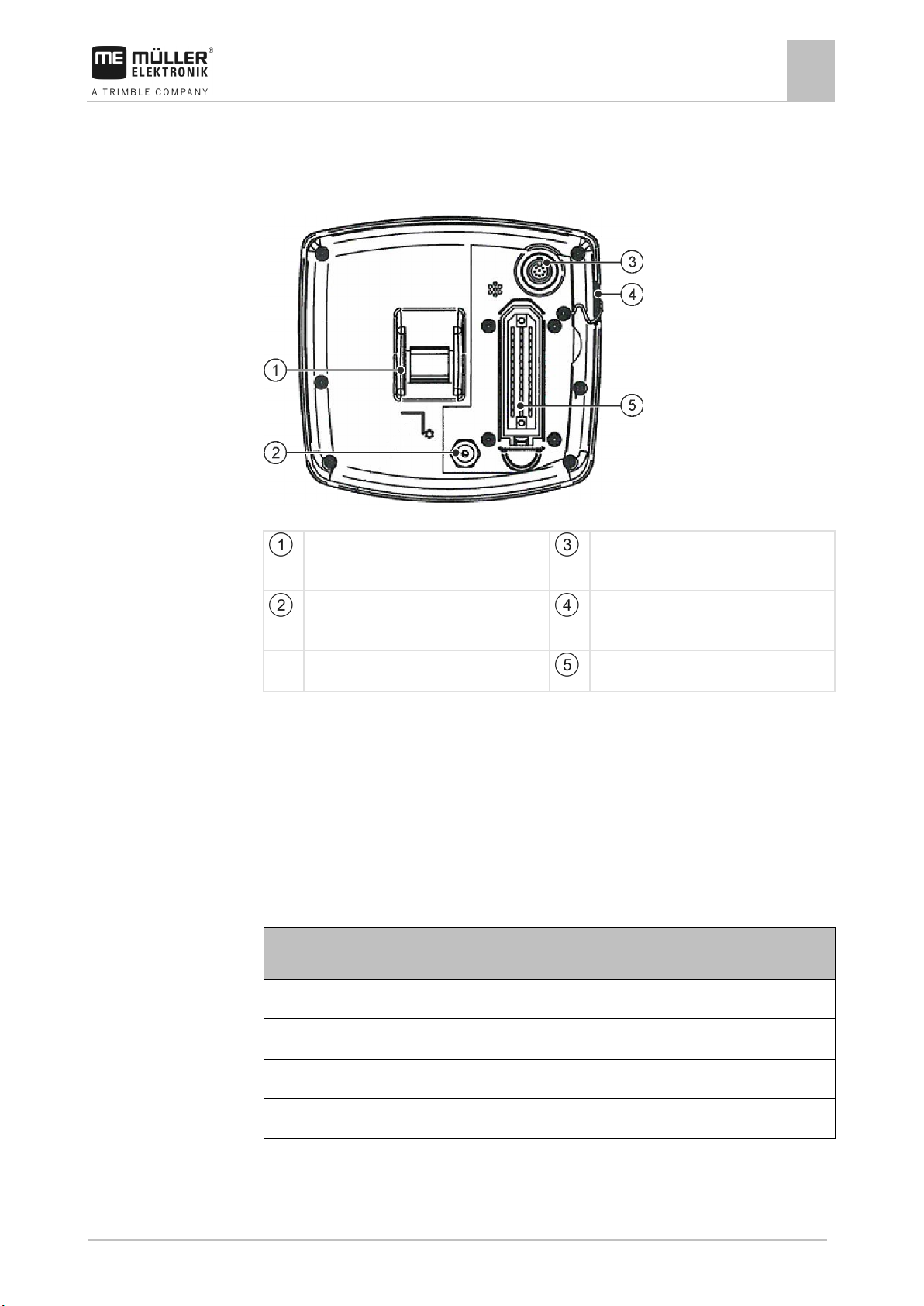
DRILL-Control - rear view
Attachment for the bracket.
Power connection cable
For connection to the battery connection
8-pin flange socket.
ASD interface for the use of SECTION-
USB port
To connect a USB memory device.
39-pin multipole connector
1. Screw the bracket onto the on-board integrated display/controller.
2. Attach the bracket with the on-board integrated display/controller in the vehicle cab
3. Connect the on-board integrated display/controller with the junction box.
4. Connect the power connection cable with the battery connection cable.
Installing the sensors on the implement
The following sensors can be installed on the implement:
Page 14
14
V2.20191001
30283620-02-EN
Pin
Cable color
Designation
1
white
0 VE
4.2.1
Mounting and installation
4
Installing the sensors on the implement
Installing the revolution sensors
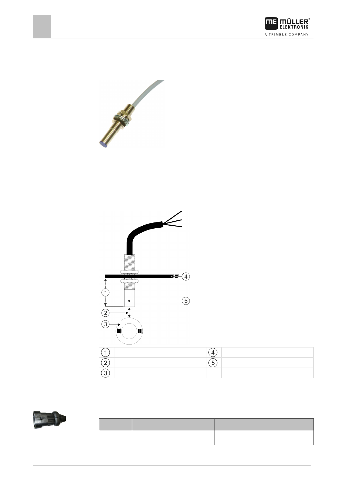
Hall element sensors are suitable as revolution sensors.
Functional principle
The Hall element establishes a connection between the green and the white cable cores. To do so,
the magnet must be held with the red side in front of the blue cap on the sensor.
Schematic overview
Min. 25 mm
Distance 5-10 mm
Ring with magnets
Attachment angle
Sensor (blue cap)
Connector pin assignment
3-pin AMP connector
Page 15
30283620-02-EN
V2.20191001
15
Pin
Cable color
Designation
2
brown
12 VE
3
green
Signal
Item number
Designation
30303623
Hall element sensor with 3-pin AMP connector, switching distance: 5-10 mm
Adjustment screw to change the reacting
distance
Pin
Cable color
Designation
1
blue
0 VE
4.2.2
Mounting and installation
Installing the sensors on the implement
4
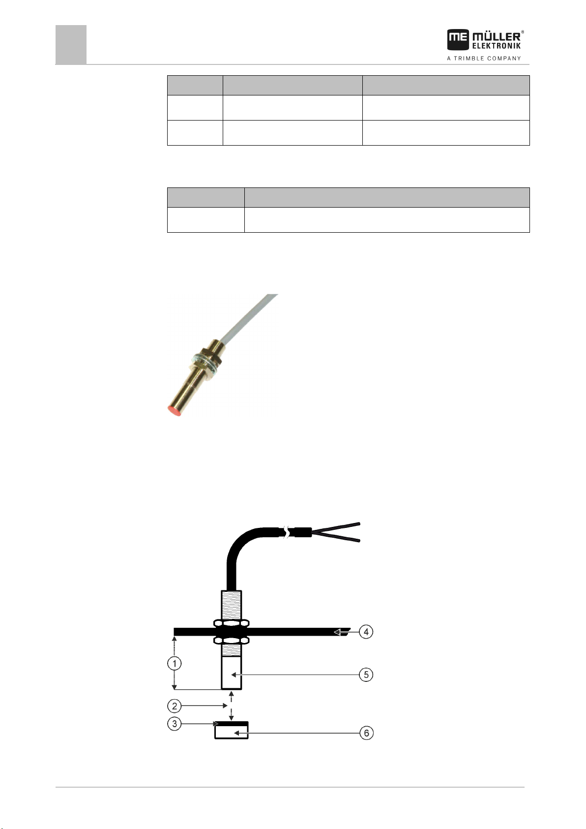
Installing the fill level sensor
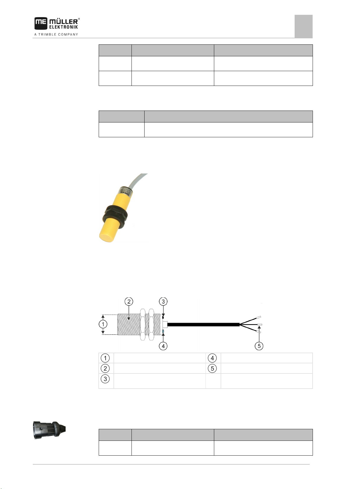
Capacitive sensors are suitable as fill level sensors.
Functional principle
A signal is sent when the flat upper side of the sensor is covered, e.g. with seed.
Spare part number
Schematic overview
Flat upper side of the sensor
Capacitive sensor
LED; shows whether the sensor reacts
Wire ferrules
Connector pin assignment
3-pin AMP connector
Page 16
16
V2.20191001
30283620-02-EN
Pin
Cable color
Designation
2
brown
12 VE
3
black
Signal
Item number
Designation
30303650
Capacitive sensor with 3-pin AMP connector
4.2.3
Mounting and installation
4
Installing the sensors on the implement
Installing the working position sensors
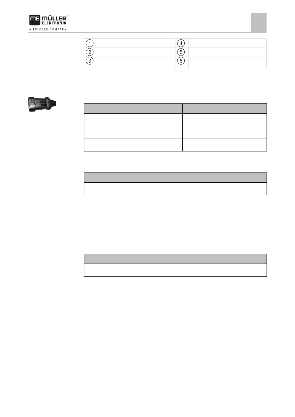
Reed contact sensors are suitable as work position sensors.
Functional principle
Spare part number
A signal is sent when the red side of a magnet is held in front of the red cap of the sensor. This
creates a connection between the signal line and the ground wire of the sensor.
Schematic overview
Page 17
30283620-02-EN
V2.20191001
17
South pole of the magnet (red side)
Magnet (nonmagnetic attachment, e.g. V2A,
copper, brass)
Pin
Cable colour
Designation
1
white
0VE
2
brown
3
green
Signal
Item number
Designation
30303615
Reed contact sensor with AMP plug
Item number
Designation
30258321
Vansco type 740 radar sensor with 1 m cable and with 3-pin AMP connector
4.2.4
Mounting and installation
Min. 25 mm
Installing the sensors on the implement
Attachment angle
4
Distance 15-25mm
Sensor (red cap)
Connector pin assignment
3-pin AMP connector
Spare part number
Installing the speed sensor
Radar sensors are suitable as speed sensors.
Consult the operating instructions for the radar sensor to find out how it has to be installed.
Spare part number
Page 18
18
V2.20191001
30283620-02-EN
5
5.1
Procedure
5.2
Basic control principles
5
Switching on the on-board integrated display/controller
Basic control principles
Switching on the on-board integrated display/controller
You have installed the on-board integrated display/controller. [➙ 13]
1.
⇨ The work screen appears.
- Switch on the on-board integrated display/controller.
Layout of the work screen
The work screen is the part of the screen where you can see the current status of the implement
based on the icons shown. Depending on the implement equipment, not all of the icons are always
shown.
Information on the metering drives
In this area you can see:
▪
indicates which metering drive is meant. The current value is always shown here.
▪
- The changed target rate you have entered.
- The seed rate for each connected metering drive. The number
Information on the rows
In this area you can see:
▪ What is being spread in each row:
–
- Seed
▪ Whether a tramline is being created on the right side or the left side of the implement:
–
- The implement is creating a tramline on the side that is marked with this icon.
Information on the additional functions
In this area, you can see if specific functions are activated.
▪
▪
▪
▪
- The waterhole mode is activated.
- The metering cells are being filled with seed.
- Both bout markers are being used.
- The left bout marker is being used.
▪
▪
- The right bout marker is being used.
- No bout marker is being used.
Page 19
30283620-02-EN
V2.20191001
19
Basic control principles
Layout of the work screen
5
▪ - The left bout marker is being used and the change mode of the bout marker is
activated.
▪
- The right bout marker is being used and the change mode of the bout marker is
activated.
▪
▪
▪
▪
- The obstacle mode is activated.
- A hopper has issued an alarm.
- The implement is in work position.
- The early stop function is activated.
Status information
In this area you can see:
▪
▪
▪
- The current speed of the implement.
- The current fan speed. The number indicates which fan is meant.
- Whether a tramline is being created.
▪
▪
- Whether tramline control is deactivated.
- Which track you are currently driving on.
Page 20
20
V2.20191001
30283620-02-EN
6
6.1
Procedure
6.2
Procedure
6.3
Procedure
Configuring the basic settings of the on-board integrated display/controller
6
Setting the date / time
Configuring the basic settings of the on-board integrated
display/controller
Setting the date / time
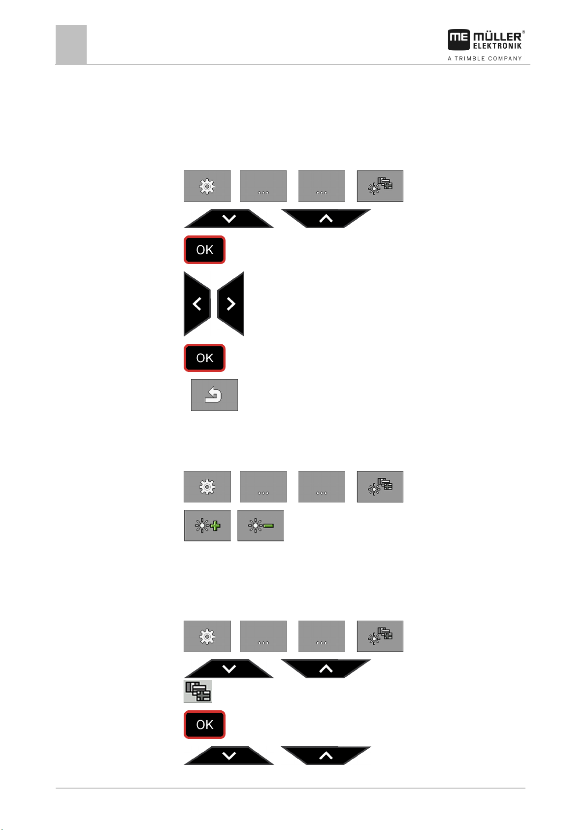
1. On the work screen, press:
> > ( ) >
2.
3.
4.
5.
- Confirm.
/ - Select the desired parameter.
- Confirm.
/ - Navigate to the date and time.
6. >
Setting the brightness
- Terminate the settings.
1. On the work screen, press:
> > ( ) >
2.
⇨ The bar in the middle of the screen shows the current brightness.
Selecting the language
/ - Increase or decrease the brightness.
1. On the work screen, press:
> > ( ) >
2.
/ - Navigate to the language settings:
3.
4.
.
- Confirm.
/ - Select the desired language.
Page 21
30283620-02-EN
V2.20191001
21
Configuring the basic settings of the on-board integrated display/controller
Selecting the language
6
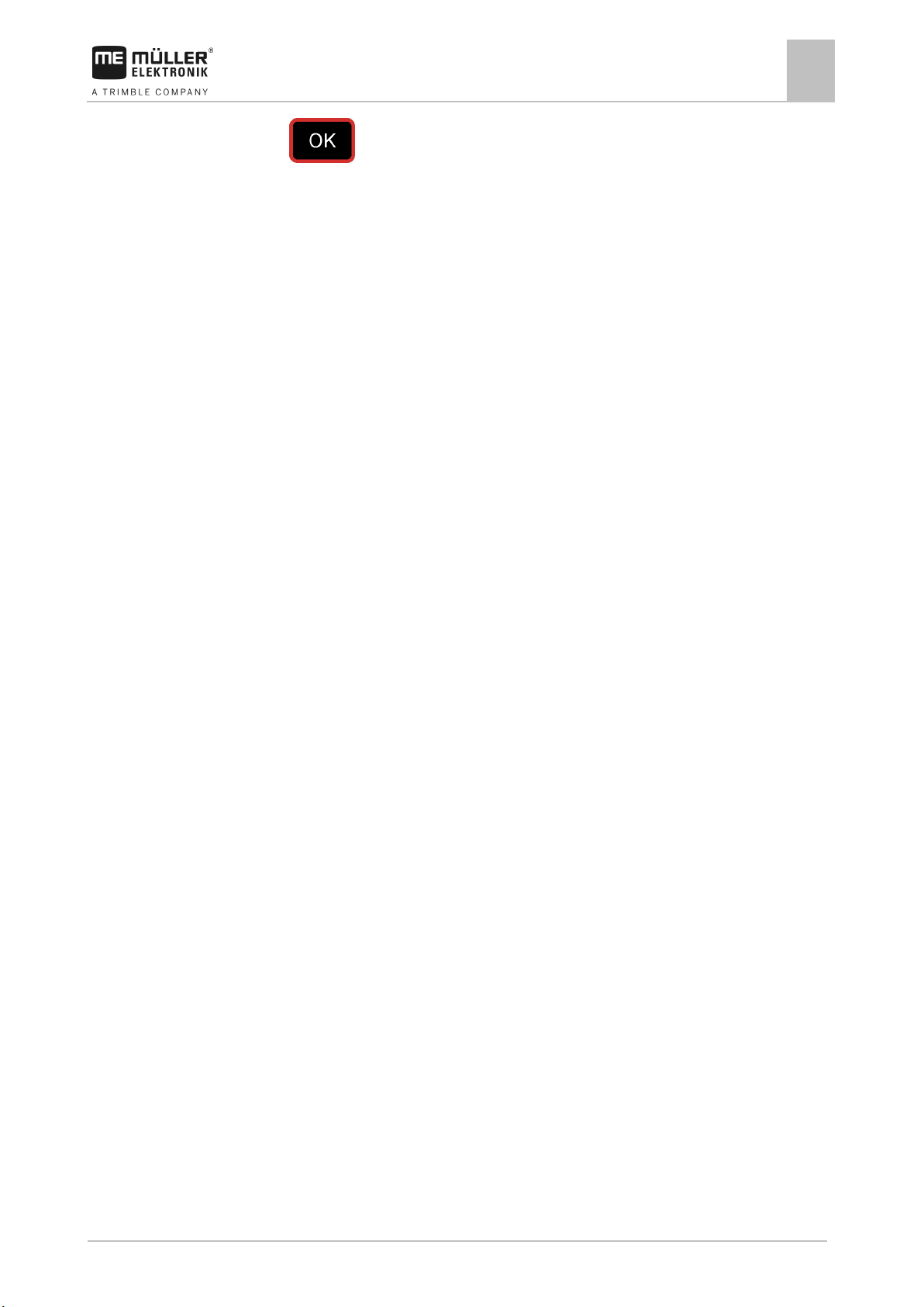
5. - Confirm.
⇨ You have selected the desired language.
⇨ When you exit the screen, the on-board integrated display/controller is restarted.
Page 22
22
V2.20191001
30283620-02-EN
7
7.1
Procedure
7.2
Procedure
Operating the implement on the field
7
Setting target rate
Operating the implement on the field
Setting target rate
On the "Settings / Metering Unit" screen, you can configure or view the following parameters for
each metering unit:
▪ "Metering Unit"
Defines the currently selected metering unit.
▪ "Min. Speed"
Defines the minimum speed that is required for application.
▪ "Max. Speed"
Defines the maximum possible speed for spreading.
▪ "Calibration Factor"
For a seeder, defines how much seed or fertilizer is spread per rotation of the metering shaft.
▪ "Adjustment"
Defines by how much percent the target rate should be changed when you change it manually
during the application. [➙ 24]
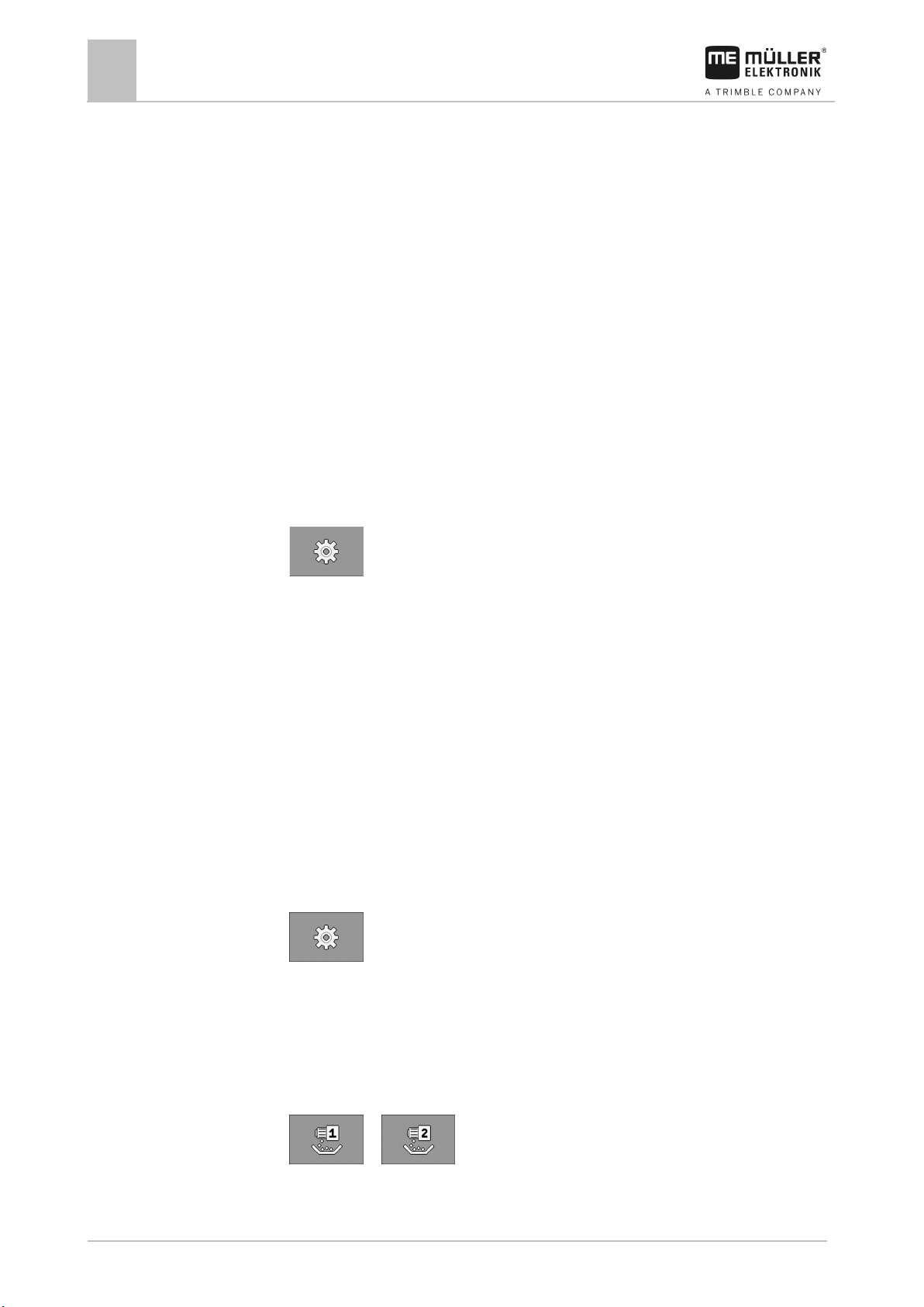
1. On the work screen, press:
⇨ The "Settings / Metering unit" screen appears.
2. Configure the parameters.
Performing a calibration
The operating instructions of the implement explain when to perform a calibration.
You can only perform a calibration when the machine is ready for operation.
You have prepared the implement and its metering drives for calibration as described in the
operating instructions from the implement manufacturer.
The hopper is filled with a sufficient quantity of seed or fertilizer. Do not fill the hopper all the
way, so that it is easier to remove or adjust a metering roll if necessary.
The implement is at a standstill.
1. On the work screen, press:
⇨ The "Settings / Metering unit" screen appears.
2. Select the metering unit for which you want to perform the calibration test.
⇨ You can see the currently selected metering unit by the number in the upper area of the
screen.
3. Enter the target rate with which you want to work later. [➙ 22]
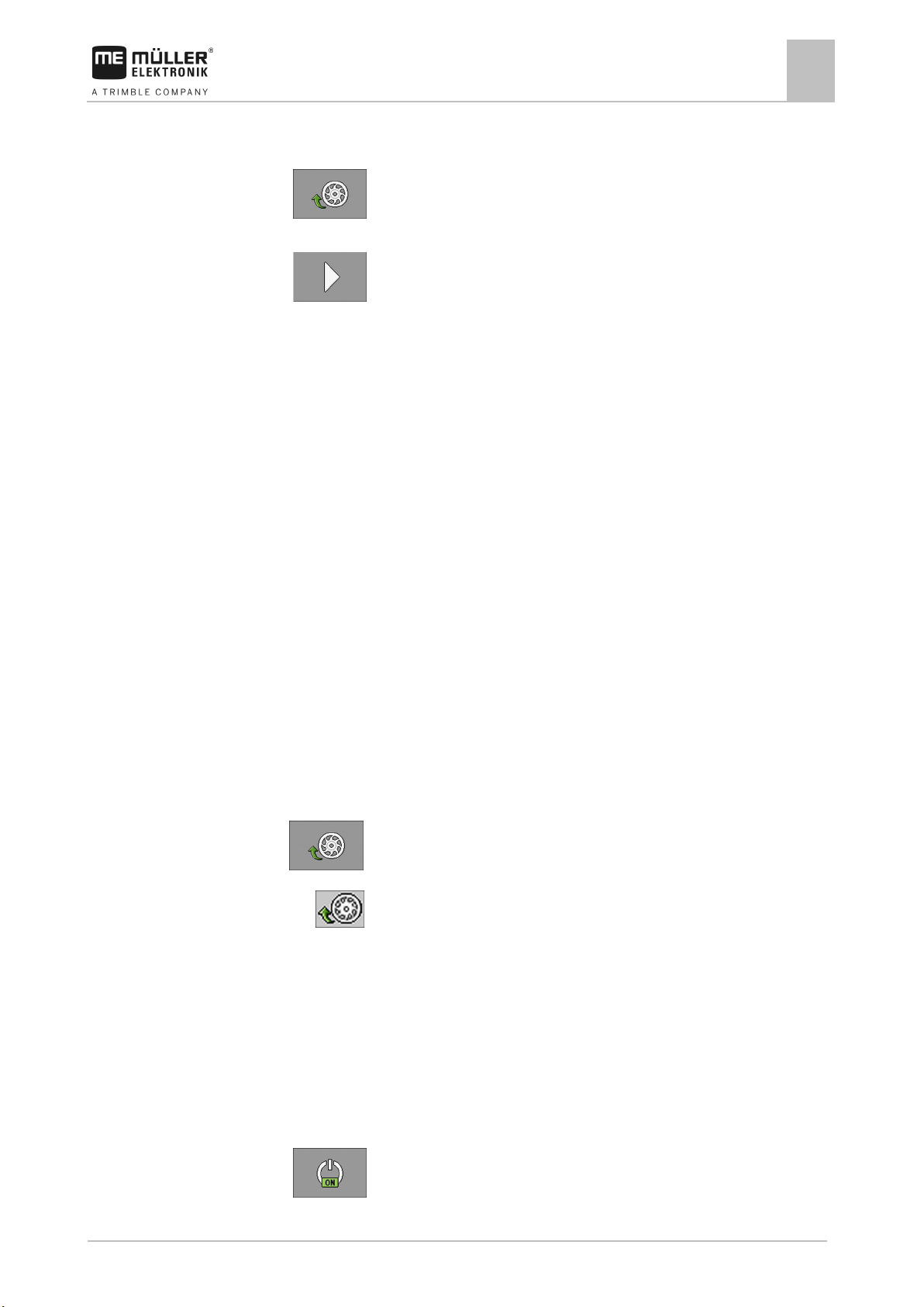
4. Press the function key of the metering drive for which you want to perform the calibration: e.g.:
or
⇨ The "Calibration" screen appears.
Page 23
30283620-02-EN
V2.20191001
23
7.3
Procedure
7.4
Procedure
Operating the implement on the field
Filling metering cells with seed
7
5. In the input box under the text "Speed correct?", enter the speed you want to use later on when
seeding.
6.
- Fill the metering cells with seed or with fertilizer.
⇨ The metering cells turn for several seconds.
7.
- Start the calibration.
8. Start the calibration on the implement. Proceed as described in the operating instructions from
the implement manufacturer.
9. Wait until the required quantity has been applied.
10. Terminate the calibration on the implement. Proceed as described in the operating instructions
from the implement manufacturer.
⇨ A screen appears on the monitor with the text: "3. Quantity".
⇨ The job computer calculates a weight from the data available and displays it in the field next
to the text "3.Quantity". It is possible that the displayed weight is different than the
calibration weight.
11. Weigh the seed that was applied during the calibration.
12. Enter the weight in the field next to the text "3. Quantity".
⇨ The job computer calculates the minimum and the maximum speed at which these target
rates are possible using the selected metering roll.
⇨ The job computer saves all of the data on the product in the product database.
Filling metering cells with seed
To be able to spread seeds from the beginning and avoid blank spots at the start of the field, you
must fill the metering cells of the seeder before you start driving. You can also use the pre-metering
function.
1. On the work screen, press
⇨ As long as the metering cells are being filled, the following icon appears on the work screen:
2. Only start driving once the icon is turned off.
Start seeding
The implement is moving.
The implement is lowered.
The metering cells are filled with seed.
The fan has reached the minimum revolution speed.
1.
- Start seeding.
Page 24
24
V2.20191001
30283620-02-EN
Function icon
Meaning
parameter. [➙ 22]
7.5
Procedure
7.6
Procedure
7.7
Operating the implement on the field
7
Stop seeding
Stop seeding
1. - Stop seeding.
⇨ On the work screen, the following message appears: "Application is stopped."
⇨ All of the metering drives are stopped.
Adjusting the target rate during operation
You can amend the target rate while working.
If you are working with several products, you can individually adjust the target rate for each product.
A number then appears on the screen and on the function icons for each product.
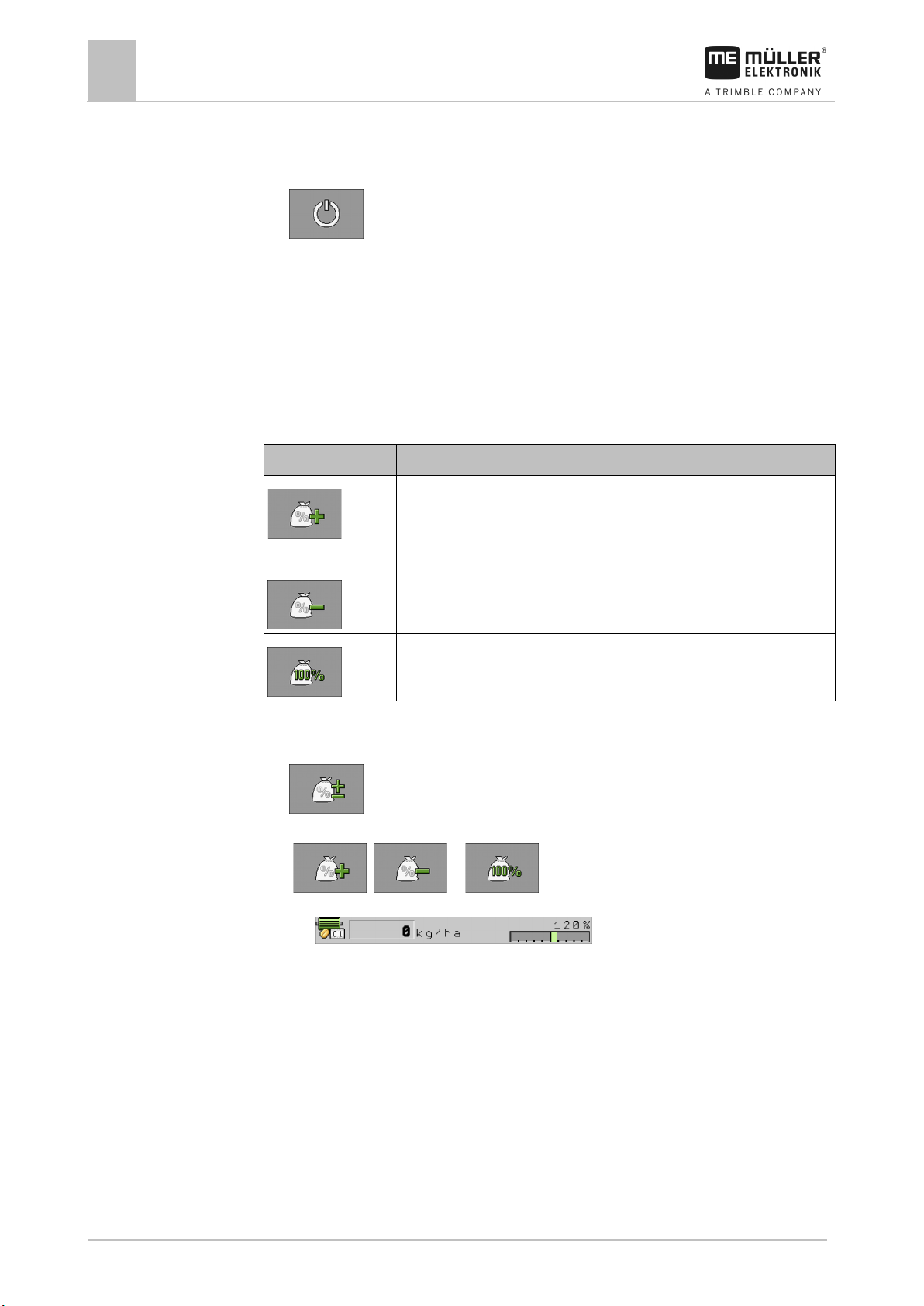
Increases the target rate.
The target rate is changed by the value that you defined in the "Adjustment"
Reduces the target rate.
Restores the target rate back to 100%.
You have defined [➙ 22] the "Target Rate" and "Adjustment" parameters.
1. On the work screen, press:
⇨ Function icons for the adjustment of the target rate appear.
2.
, or - Change the target rate.
⇨ The target rate of the metering units will be changed:
⇨ The job computer regulates the seeding according to the new target rate.
Using tramline control
The job computer can help you in creating tramlines for the tyres of other vehicles such as sprayers.
A tramline is created by closing the seed tubes to the seeding coulters. This creates an area behind
the implement where there is no seeding.
When the tramline control is activated, the tracks are counted to create the tramlines for the defined
tracks. The tracks are counted as soon as the implement is lifted out of the soil.
Page 25
30283620-02-EN
V2.20191001
25
repeated.
the implement.
created for this track. No icon appears.
Function icon
Meaning
leaving the field.
computer automatically activated the next track.
automatic mode.
Procedure
Operating the implement on the field
Using tramline control
7
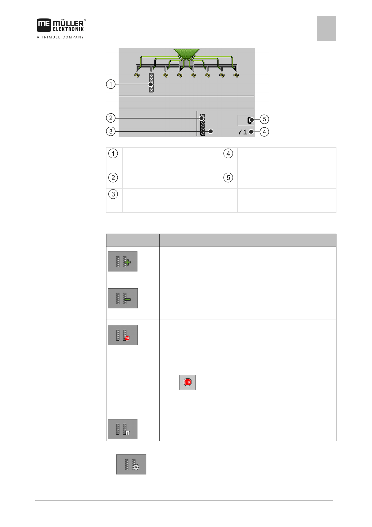
Areas on the work screen that are relevant for the creation of tramlines
A tramline is being created.
Tramline rhythm length
Number of tracks until the tramline rhythm is
A tramline is being created on the left side of
Tramline control is not active on this side of
the implement. Therefore, no tramline will be
Controls
Number of the current track
Increases the number of the track.
For example, so that you can continue working again at the same track after
Reduces the number of the track.
For example, when you have lifted the implement within a track and the job
Deactivates the tramline control.
If you deactivate the tramline control, the tracks are no longer counted. For
example, this can be used when working the headlands. The selected
tramline rhythm is then no longer relevant.
If tramline control is deactivated, the following icon appears on the work
screen:
If this icon appears, the bout markers are also not switched further in
Opens the screen for selecting a tramline rhythm for a seeder.
1. On the work screen, press:
⇨ You can change the number of the track.
Page 26
26
V2.20191001
30283620-02-EN
or
or
or
7.7.1
Procedure
7.7.2
Operating the implement on the field
7
Using tramline control
⇨ You can configure the tramline control.
Configuring the tramline control
To configure tramline control, proceed as follows:
1. Determine the implement type. [➙ 26]
2. Select a tramline rhythm. [➙ 27]
Determining the machine type
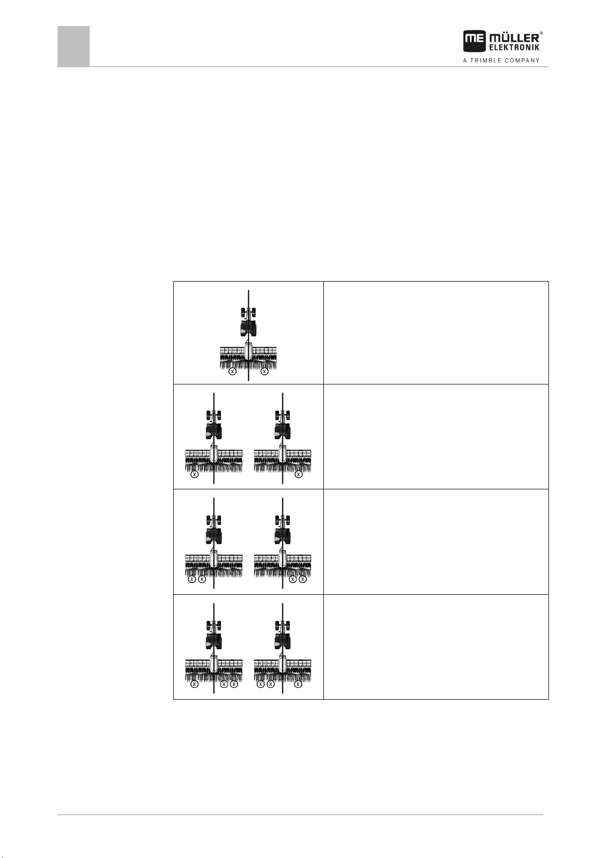
If you are working with a seeder with tramline control, you have to know where and how many
tramline mechanisms are installed on your seeder. The following overview shows how tramline
mechanisms can be installed on your seeder.
▪ One tramline mechanism on each side of the seeder.
▪ One tramline mechanism on one side of the seeder.
▪ Two tramline mechanisms on one side of the seeder.
▪ One tramline mechanism on one side and two
tramline mechanisms on the other side of the seeder.
Page 27
30283620-02-EN
V2.20191001
27
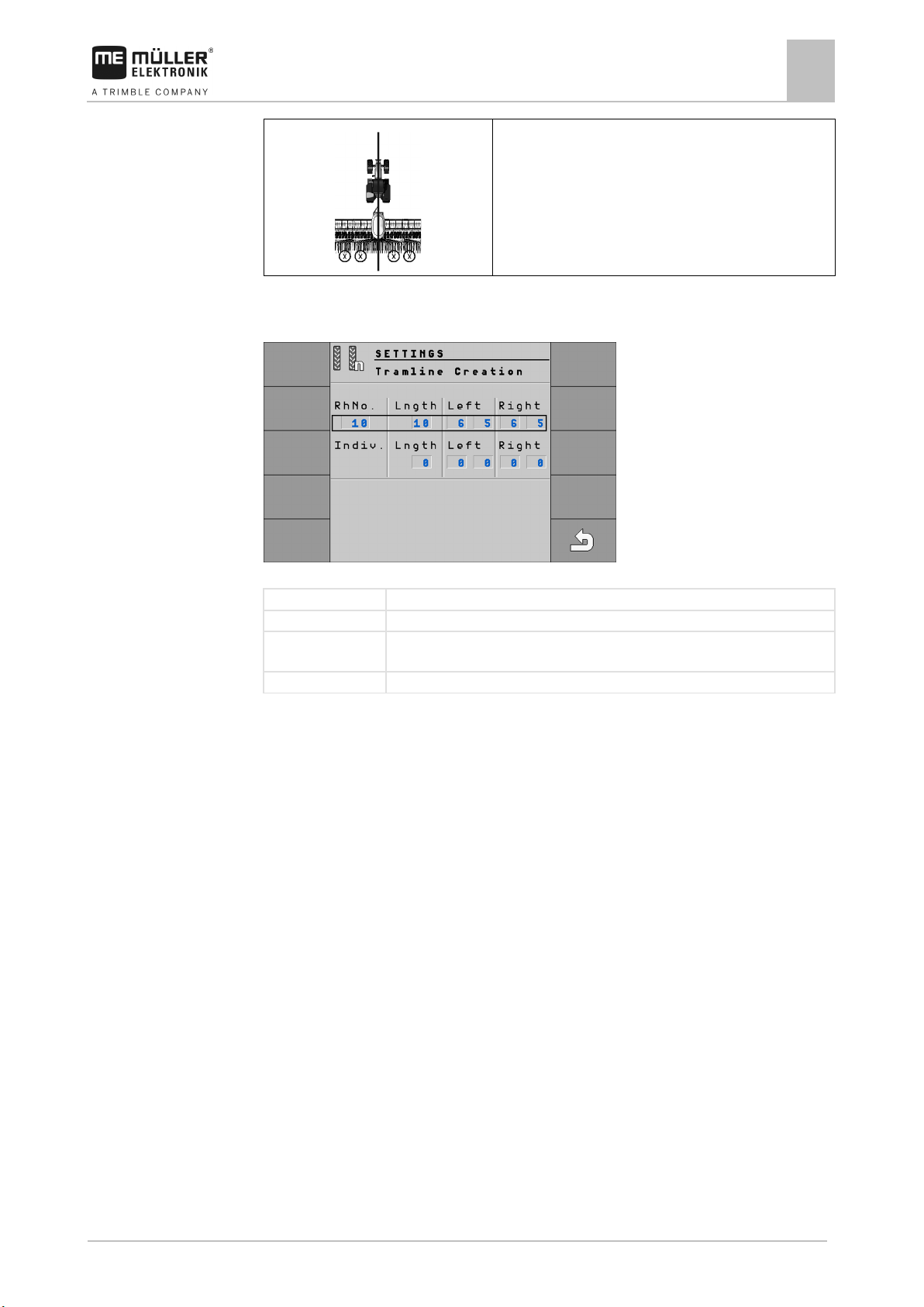
RhNo.
Number of the tramline rhythm
Length
Number of tracks until the tramline rhythm is repeated.
create a tramline. Up to two track numbers can be entered for each direction.
Indiv
Here you can define your own tramline rhythm.
7.7.3
Procedure
Operating the implement on the field
Using tramline control
7
▪ Two tramline mechanisms on each side of the seeder.
Selecting tramline rhythm
“Settings / Tramline” screen for a seeder
Left, right This shows the passes in which the “left” or “right” seed tubes are closed in order to
This is how to select the proper tramline rhythm:
You know the working width of your implement.
You know the working width of your sprayer.
You know which side of your seeder is used to create tramlines and how many tramline
mechanisms your seeder has on each side. [➙ 26]
1. Decide whether you want to start working on the left or the right field edge.
2. Perform the following calculation:
Working width of the sprayer:Working width of the seeder
e.g.: 12:3=4; 15:3=5 or 20:3=6.67
⇨ The following results are possible: Even numbers (2; 4; 6; etc.), uneven numbers (3; 5; 7;
etc.) and decimals (1.5; 4.5; 5.33; etc.)
⇨ Depending on the result, you have to select a different tramline rhythm. You can find the
results in the “Results of the calculation” column in the following sections.
3. Find out which section contains the proper tramline rhythm for you.
⇨ Even numbers - Even tramline rhythms [➙ 28]
⇨ Uneven numbers - Uneven tramline rhythms [➙ 31]
⇨ Decimal numbers - Special tramline rhythms [➙ 32]
4. Select the table with the proper rhythm numbers in the chapters mentioned in step 3. The tables
can differ depending on the side of the seeder that is used to create the tramlines, the number of
tramline mechanisms on the seeder and the working start.
Page 28
28
V2.20191001
30283620-02-EN
Possible position
of the flaps
Result of the
calculation
RhNo.
Length
Left
Right
Example
Operating the implement on the field
7
Using tramline control
5. On the work screen, press:
>
⇨ The “Settings / Tramlines” screen appears.
6. Select the proper rhythm number.
Enter an individual tramline rhythm if the rhythm number indicated in the table is “999”. [➙ 35]
⇨ You can start working.
Creating an even tramline rhythm
Two even tramline rhythms can be created during one or two passes.
▪ In one pass if the tramlines are created on both sides of the seeder.
▪ In two passes if the tramlines are created on one side of the seeder and a tramline mechanism is
installed on the side.
▪ In one pass if the tramlines are created on one side of the seeder and two tramline mechanisms
are installed on the side.
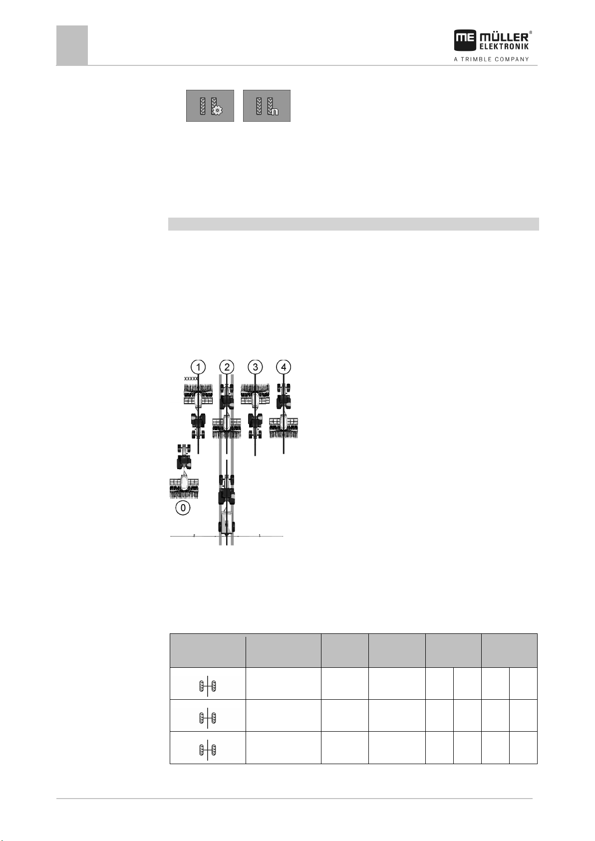
Creating tramlines on both sides of the seeder simultaneously
▪ The figure shows the 4S tramline rhythm.
▪ The tramlines are created during track 2. (ex.: working width of the sprayer = 12 m, working
width of the seeder = 3 m)
▪ Track 0 must be performed separately. To avoid overlapping, use the "Half width shutoff system"
function.
▪ The tramline control must be deactivated for track 0.
2 2S 2 1 1
4 4S 4 2 2
6 6S 6 3 3
Page 29
30283620-02-EN
V2.20191001
29
of the flaps
calculation
Possible position
of the flaps
Result of the
calculation
RhNo.
Length
Left
Right
Example
Operating the implement on the field
Using tramline control
7
Possible position
Result of the
RhNo. Length Left Right
8 8S 8 4 4
10 10S 10 5 5
12 12S 12 6 6
14 999 14 7 7
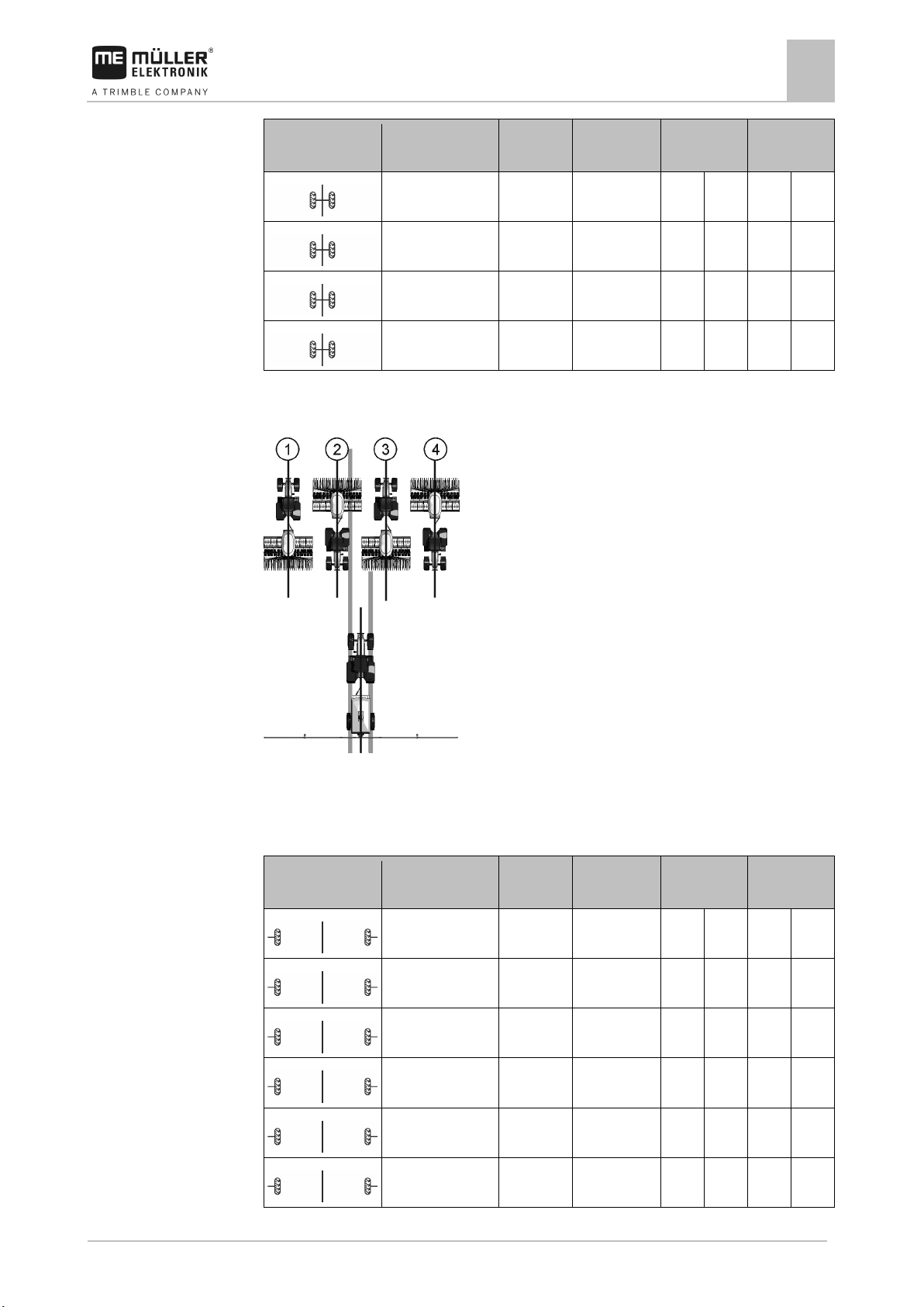
Creating tramlines on one side of the seeder and with only one tramline mechanism
▪ The figure shows an individual tramline rhythm.
▪ The tramlines are created during tracks 2 and 3. (ex.: working width of the sprayer = 12 m,
working width of the seeder = 3 m)
Working start at the left field edge
2 999 2 1 2
4 999 4 2 3
6 999 6 3 4
8 999 8 4 5
10 999 10 5 6
12 999 12 6 7
Page 30
30
V2.20191001
30283620-02-EN
of the flaps
calculation
of the flaps
calculation
Example
Operating the implement on the field
7
Using tramline control
Possible position
Result of the
RhNo. Length Left Right
14 999 14 7 8
Working start at the right field edge
Possible position
Result of the
RhNo. Length Left Right
2 999 2 1 2
4 999 4 2 3
6 999 6 3 4
8 999 8 4 5
10 999 10 5 6
12 999 12 6 7
14 999 14 7 8
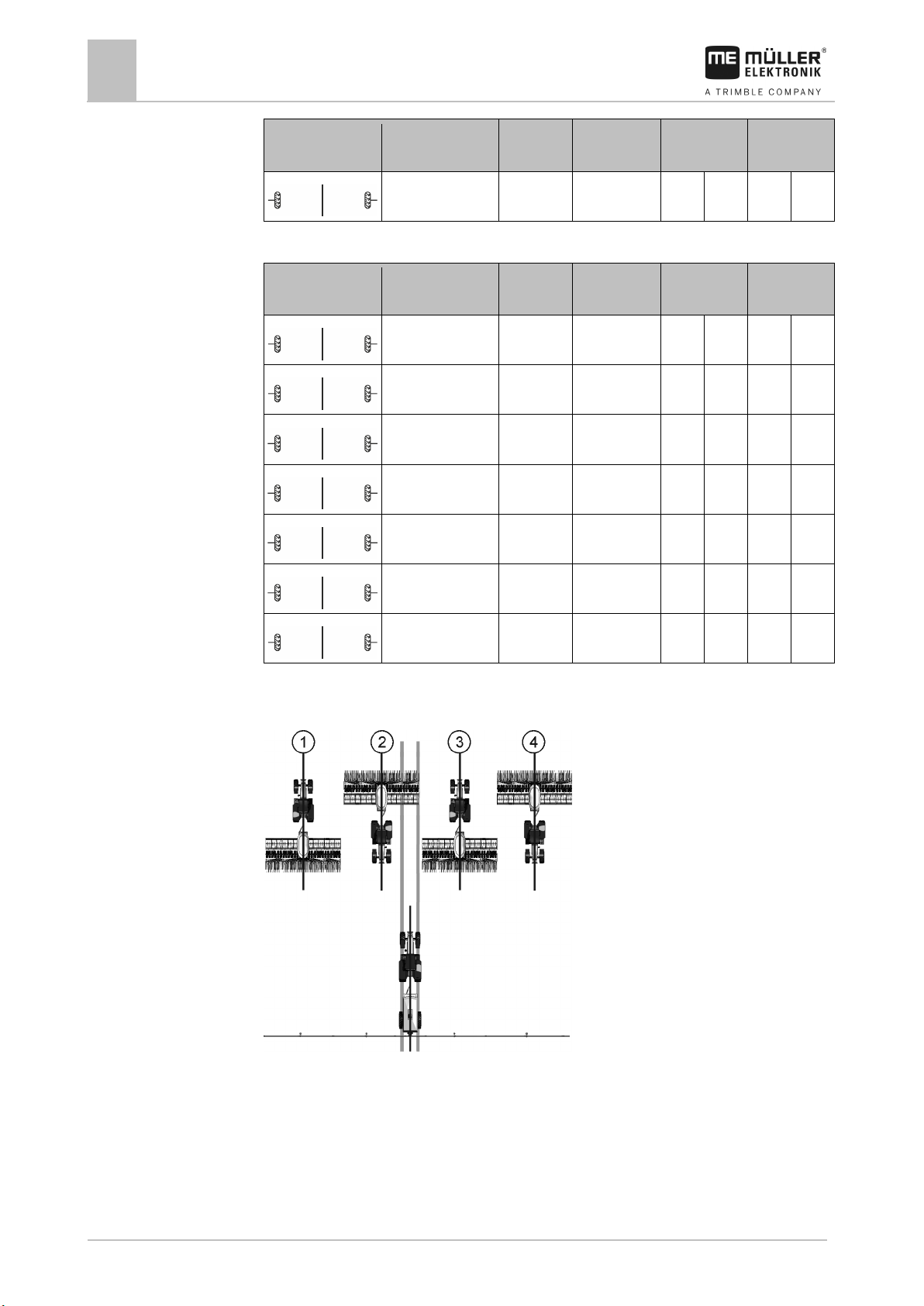
Creating tramlines on one side of the seeder and with two tramline mechanisms
▪ The figure shows an individual tramline rhythm.
▪ The tramlines are created during track 2. (ex.: working width of the sprayer = 24m, working width
of the seeder = 6m)
Page 31
30283620-02-EN
V2.20191001
31
Possible position
of the flaps
Result of the
calculation
RhNo.
Length
left
right
Possible position
of the flaps
Result of the
calculation
RhNo.
Length
left
right
Operating the implement on the field
Working start at the left field edge
Using tramline control
7
2 999 2 1
4 999 4 2
6 999 6 3
Working start at the right field edge
2 999 2 1
4 999 4 2
6 999 6 3
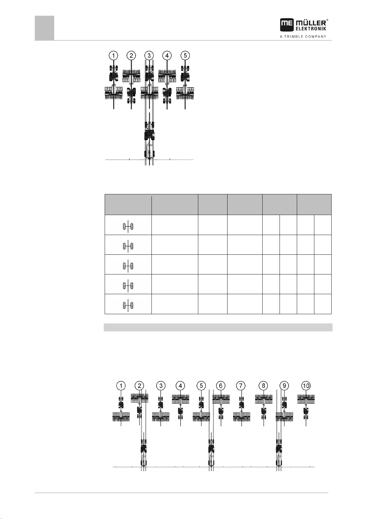
Creating uneven tramline rhythms
Uneven tramline rhythms are always created in one track. Uneven tramline rhythms can only be
created if the tramlines are created with both sides of the seeder.
Page 32
32
V2.20191001
30283620-02-EN
Possible position
of the flaps
Result of the
calculation
RhNo.
Length
left
right
Example
Example
Operating the implement on the field
7
Using tramline control
▪ The figure shows tramline rhythm 5.
▪ The tramlines are created during track 3. (ex.: working width of the sprayer = 15m, working width
of the seeder = 3 m)
3 3 3 2 2
5 5 5 3 3
7 7 7 4 4
9 9 9 5 5
11 11 11 6 6
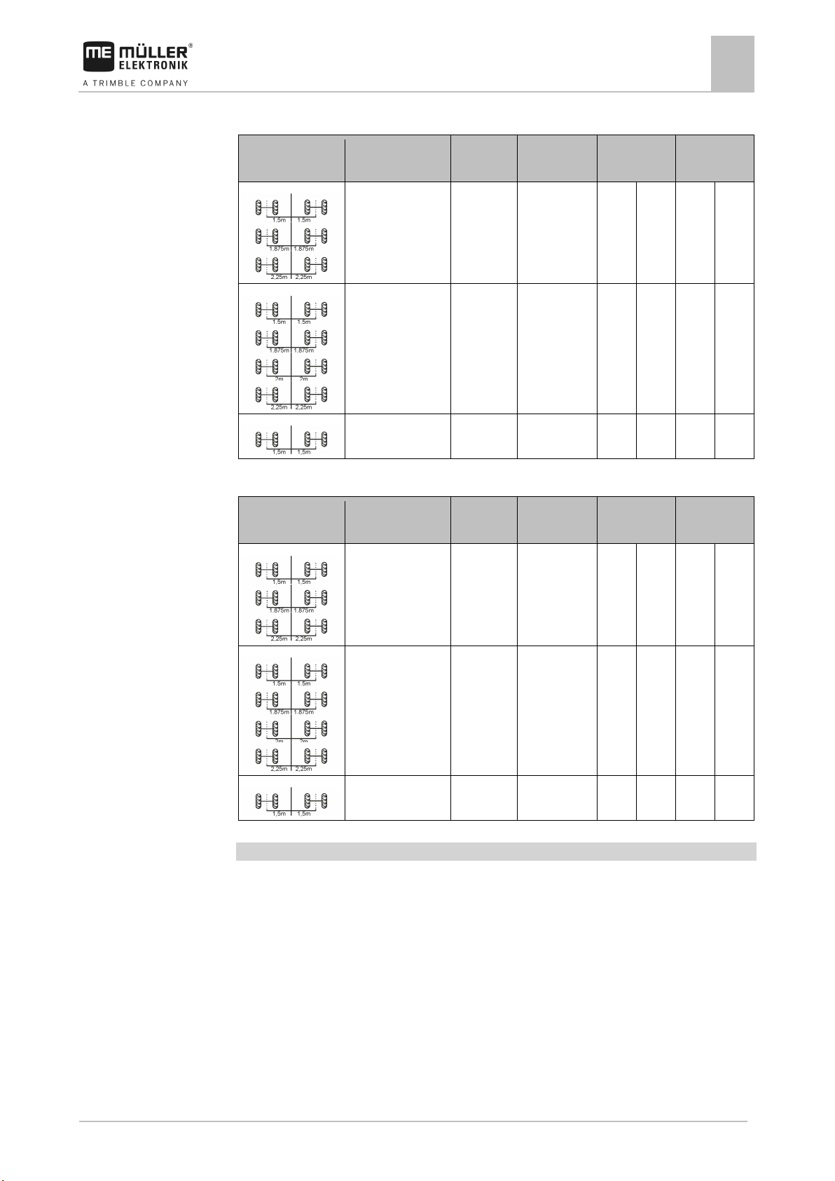
Creating special tramline rhythms
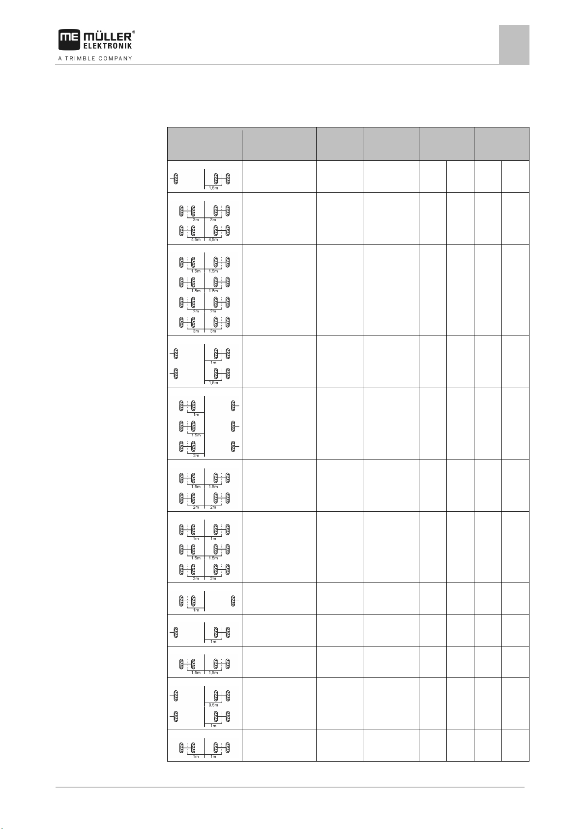
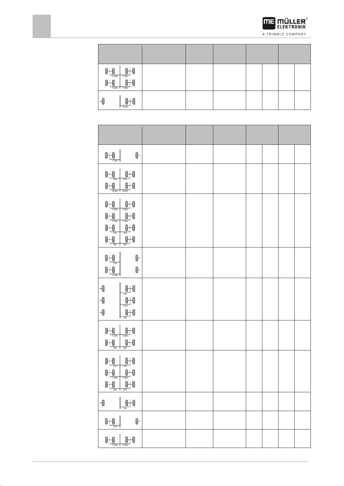
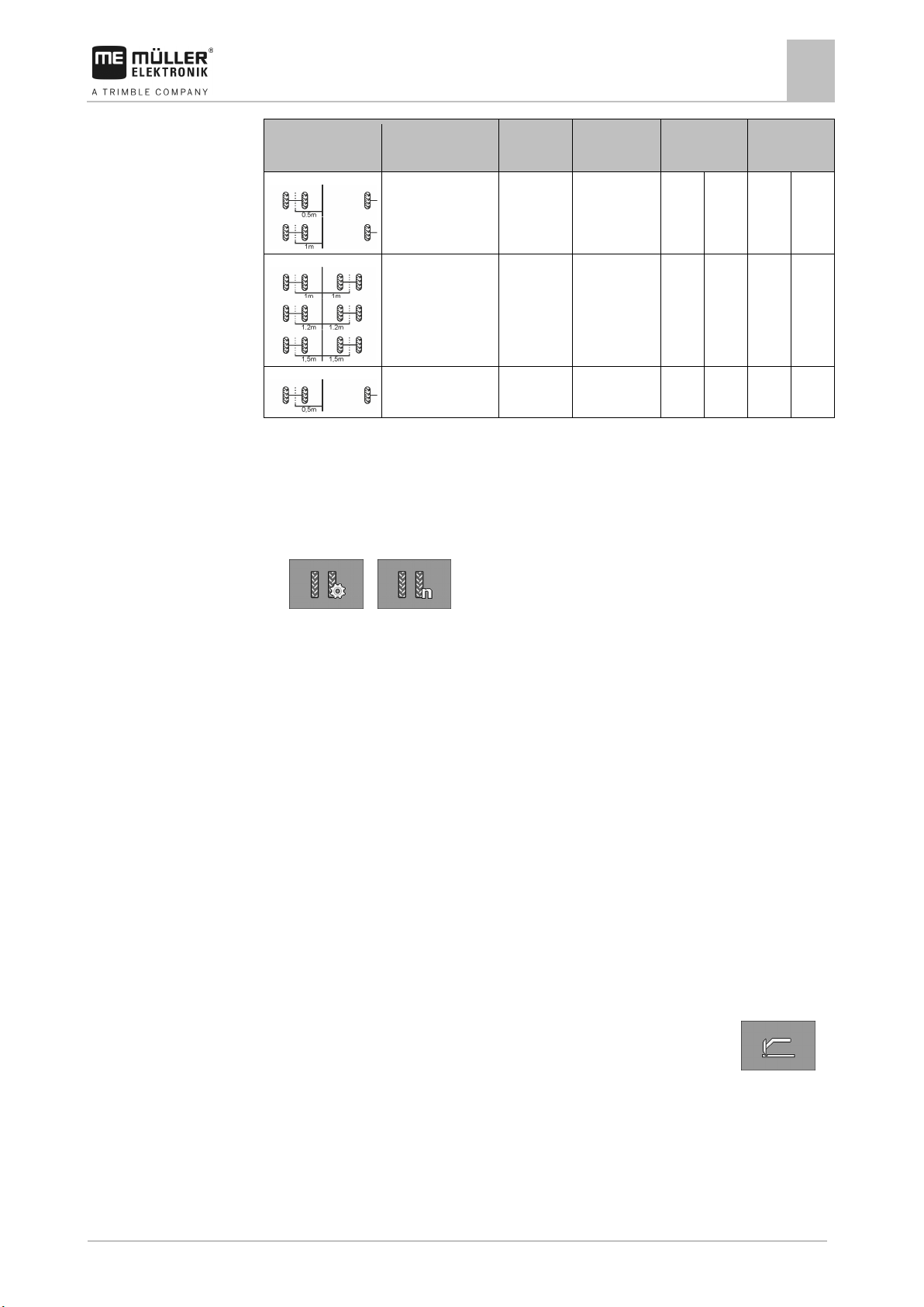
Special tramline rhythms are always created in four tracks. Special tramline rhythms can only be
created if the tramlines are created with both sides of the seeder.
▪ There is one tramline mechanism on one side of the seeder and two tramline mechanisms on
the other side of the seeder.
▪ Two tramline mechanisms are installed on both sides of the seeder.
▪ The figure shows tramline rhythm 20.
Page 33
30283620-02-EN
V2.20191001
33
Possible position
of the flaps
Result of the
calculation
RhNo.
Length
Left
Right
Operating the implement on the field
Using tramline control
7
▪ The tramlines are created during tracks 2, 5, 6 and 9. (ex.: working width of the sprayer = 20m,
working width of the seeder = 6m)
Working start at the left field edge
1.33 999 4 3 2 1 4
1.5 22 6 4 3 6 1
2.5 16 10 7 4 9 2
2.67 999 8 5 4 7 2
3.33 20 10 9 2 6 5
3.5 28 14 13 2 9 6
4.5 18 18 16 3 12 7
4.67 999 14 3 12 7 8
5.33 24 16 9 8 14 3
5.5 999 22 14 9 3 20
6.67 999 20 10 11 4 17
7.5 30 30 27 4 19 12
Page 34
34
V2.20191001
30283620-02-EN
of the flaps
calculation
Possible position
of the flaps
Result of the
calculation
RhNo.
Length
Left
Right
Operating the implement on the field
7
Using tramline control
Possible position
Result of the
RhNo. Length Left Right
9.33 999 28 14 15 2 24
Working start at the right field edge
1.33 999 4 1 4 3 2
1.5 23 6 6 1 4 3
2.5 15 10 9 2 7 4
2.67 999 8 7 2 5 4
3.33 21 10 6 5 9 2
3.5 29 14 9 6 13 2
4.5 19 18 12 7 16 3
4.67 999 14 7 8 3 12
5.33 25 16 14 3 9 8
5.5 999 22 3 20 14 9
Page 35
30283620-02-EN
V2.20191001
35
of the flaps
calculation
7.7.4
Procedure
7.8
Example
Operating the implement on the field
Operating the hydraulic system with the job computer
7
Possible position
Result of the
RhNo. Length Left Right
6.67 999 20 4 17 10 11
7.5 31 27 19 12 27 4
9.33 999 28 2 24 14 15
Programming individual tramline rhythms
If you realize that the tramline rhythms stored do not match your work method, you can program an
individual tramline rhythm.
1. On the work screen, press:
>
⇨ The “Settings / Tramlines” screen appears.
2. In the “RhNo.” field, select rhythm number “999”.
⇨ All of the parameters for the stored tramline rhythms are hidden.
3. Configure the “Length”, “Left” and “Right” parameters for individual tramline rhythm.
4. The values you have entered will remain in the screen also when you have selected some other
tramline rhythm. To use an individual tramline rhythm, you always have to select the “RhNo.”
“999”.
Operating the hydraulic system with the job computer
The Müller-Elektronik job computer is used to adjust the position of the hydraulic valves so that the oil
pressure is routed to specified parts of the seeder.
When operating the seeder with the job computer, remember that the job computer cannot control the
oil pressure.
You have to use the control unit in the tractor to generate pressure in the system.
Operation with these systems can then look like this:
1. Press a function key on the on-board integrated display/controller. For example,
the left-hand bout marker.
⇨ The function icon appears on the work screen. This confirms that the hydraulic valve is
ready and this function can now be controlled hydraulically.
2. Actuate the control unit of the hydraulic system in the tractor that is responsible for the bout
marker.
⇨ The pressure builds up.
for
Page 36
36
V2.20191001
30283620-02-EN
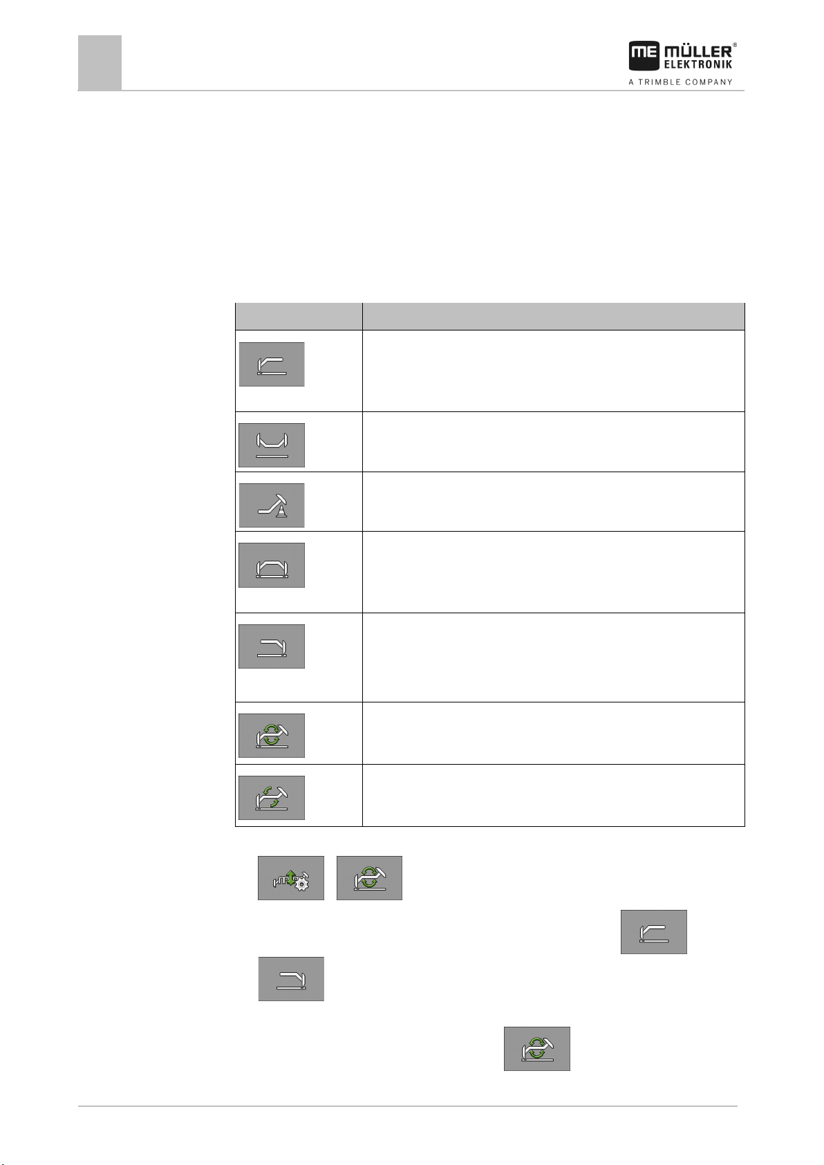
Function icon
Meaning
For example, to work on the headlands.
on the implement.
For example, to work on the headlands.
The bout marker is always changed when you lift the implement.
The bout marker is changed when you press the function key.
7.8.1
Procedure
Operating the implement on the field
7
Operating the hydraulic system with the job computer
⇨ The left bout marker is lowered.
3. If you now remove the pressure from the valve, the left-hand bout marker will be lifted.
⇨ The function icon must appear on the work screen, both when you lower the bout marker
and when you lift it.
The following sections explain which hydraulic functions can be operated with the job computer.
Operating bout markers
You can use bout markers as you work to mark a pass.
Use the left bout marker only. The bout marker is not changed when lifting
the implement.
Deactivate both bout markers.
Lift the bout marker to pass over obstacles. The implement itself is not
lifted.
Use both bout markers at the same time.
You can use this function e.g. if you do not have a pre-emergence marker
Use the right bout marker only.
The bout marker is not changed when lifting the implement.
Use the bout markers alternately.
Change the bout markers manually.
1. On the work screen, press:
>
2. Select the side on which the bout marker should be lowered first. Press:
or
⇨ The work screen shows which bout marker has been lowered.
3. To activate automatic bout marker control press:
Page 37
30283620-02-EN
V2.20191001
37
Function icon
Meaning
7.8.2
Procedure
7.9
7.9.1
Procedure
Operating the implement on the field
Viewing results
7
⇨ The left bout marker is lowered.
4. Press
⇨ Depending on the settings, an icon for the bout marker appears on the work screen.
again to switch between the left and the right bout markers.
Using the waterhole mode
You can lift or lower the implement while working without interruption. By doing so, you prevent:
▪ The implement from sinking into a puddle.
▪ A new track from being counted.
▪ The tramline from being switched.
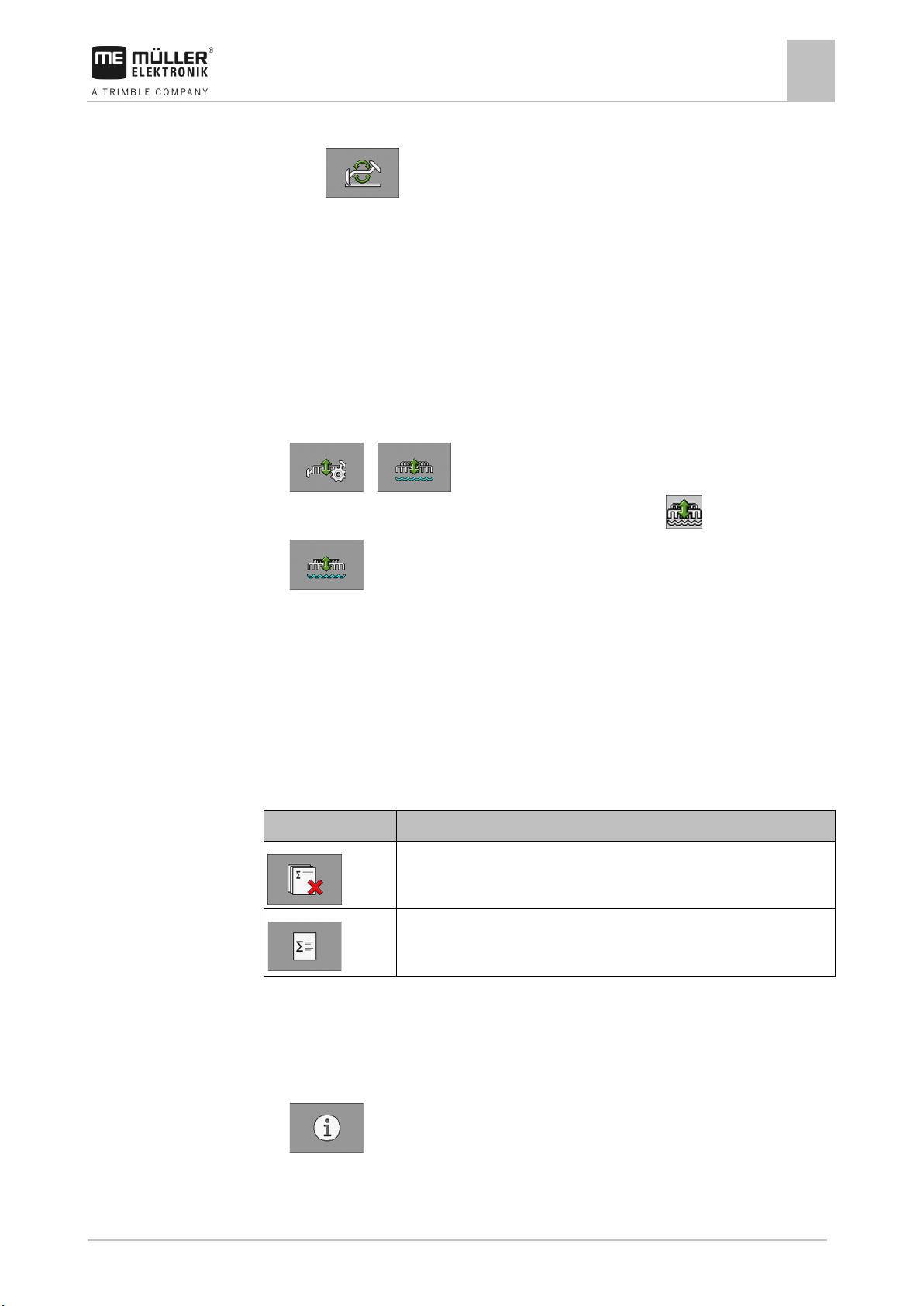
The implement is lowered.
1. On the work screen, press:
>
⇨ The icon for the waterhole mode appears on the work screen:
2.
- Terminate the waterhole mode.
⇨ The icon for the waterhole mode disappears.
Viewing results
Results
The “Results” screen shows how much of each product you have spread and on which area.
You can reset the counters on this screen before starting work.
Resets the counter.
Calls up the "Total results" screen.
The following counters are available:
▪ “Area” - Area on which the implement was in work position.
▪ “Quantity” - Applied quantity.
▪ “Area Output” - Applied area per hour.
1. On the work screen, press:
⇨ The “Results” screen appears.
Page 38
38
V2.20191001
30283620-02-EN
7.9.2
Procedure
Operating the implement on the field
7
Viewing results
Total results
On the “Total results” screen, you see the counter that documents the work performed since the
initial startup of the job computer.
The following counters are available:
▪ “Service Hours” - Time for which the job computer is switched on.
▪ “Total Time” - Time for which the job computer was spreading.
▪ “Total Distance” - Processed distance.
▪ “Total Area” - Applied area.
▪ “Area Output” - Applied area per hour.
▪ "Total Quantity" - For each metering drive.
1. On the work screen, press:
>
⇨ The “Total Results” screen appears.
Page 39
30283620-02-EN
V2.20191001
39
Source
To configure the speed source
implement
Simulated speed
Entering the simulated speed [➙ 40]
8
8.1
8.1.1
Procedure
Configuring the on-board integrated display/controller for work
Configuring the on-board integrated display/controller for work
Selecting and configuring the speed source
8
Selecting and configuring the speed source
You must enter the source from which the on-board integrated display/controller obtains the current
speed. The configuration procedure can differ depending on the speed source.
Possible speed sources
Impulse-transmitting speed
Calibrating the speed sensor using the 100m method [➙ 39]
sensor mounted on the
Calibrating the speed sensor with the 100m method
When calibrating the speed sensor with the 100m method, you determine the number of impulses
received by the speed sensor in a distance of 100m. When you know the amount of impulses, the job
computer can calculate the current speed.
After the first calibration, you can manually enter the number of impulses as the value of the
“Calibration Factor ” parameter.
1. Drive the implement onto the field.
2. Mark the tire position on the ground. For example with a stone.
3. Measure a straight route of 100 m and mark the end.
4. On the work screen, press:
> > ( )
⇨ "Settings / Speed" screen appears.
5. In the "Speed source" parameter, select the "Implement" value
6.
- Call up the "Calibration" screen.
⇨ "Calibration" screen appears.
7.
- Start the calibration.
8. Travel the marked route.
⇨ During travel, the counted impulses are displayed in the "No. of impulses" field.
9.
- Press when you have reached the end.
⇨ The calibration is terminated.
Page 40
40
V2.20191001
30283620-02-EN
CAUTION
Injury caused by working machine
If the function is activated when the implement is at a standstill, the driver can activate functions that
◦ Make sure that no one is close to the implement.
8.1.2
Procedure
8.2
Procedure
Configuring the on-board integrated display/controller for work
8
Associating products with a hopper
Entering the simulated speed
To test the proper functioning of a sensor, you can simulate a speed.
can otherwise only be activated during travel. This can cause injury to persons standing close to the
implement.
1. On the work screen, press:
> > ( )
⇨ The "Settings / Speed" screen appears.
2. In the "Speed Source" parameter, select the value "Simulation".
3. In the "Sim.Speed" parameter, enter the speed to be simulated.
⇨ The desired speed will be simulated.
⇨ When you restart the job computer, the simulated speed will automatically be set to the value
"0".
Associating products with a hopper
On the “Settings / Hopper” screen, you must assign a product to each hopper. The following
parameters are possible:
▪ “Hopper”
Defines the currently selected hopper.
▪ “Assigned Product”
Defines which product should be assigned with a hopper.
▪ "Rename"
Defines whether the product should get a new name.
▪ “Status”
Shows whether the associated product is currently activated.
1. On the work screen, press:
> > ( )
⇨ The "Settings / Hopper" screen appears.
2.
- Select the hopper to which you want to associate a product.
3. Configure the parameters.
4.
- Optionally, you can change the status of the selected product.
Page 41
30283620-02-EN
V2.20191001
41
Function icon
Implement parts
General equipment of the implement [➙ 43]
Function icon
Meaning
9
9.1
9.1.1
Procedure
9.1.2
Configuring the implement equipment
Configuring the implement equipment
General information on the configuration
9
General information on the configuration
Performing the configuration
The equipment of the implement is configured in a separate area of the application. You will find
different parameters within the area.
To perform the calibration:
1. On the work screen, press:
> > ( ) >
⇨ The "Settings" screen appears.
⇨ You will find parameters for an implement element behind each function icon. The following
section explains which function icon represents which implement element.
⇨ You can now configure the desired parameters.
Layout of the configuration screen
During the configuration, you will see the following screen:
Function icons for the implement elements
Hoppers [➙ 43]
Metering units [➙ 43]
Rows [➙ 44]
Sections [➙ 44]
Function icons for operations
Scrolls up.
Scrolls down.
Page 42
42
V2.20191001
30283620-02-EN
Function icon
Meaning
9.1.3
Procedure
9.1.4
Configuring the implement equipment
9
General information on the configuration
Starts the screen for the next part of the same type.
Starts the screen for the next part of the same type.
Password entry
Return
Configuration sequence
The configuration differs according to the machine type that you are using and the implement
equipment. This section shows a possible sequence for the configuration of a seeder.
You can see which parameters have to be set for the individual configurations in the indicated
chapters.
You have called up the configuration screen.
1. Configure the implement. [➙ 43]
2.
3.
4.
5.
- Configure the hoppers. [➙ 43]
- Configure the metering units. [➙ 43]
> - Configure the rows. [➙ 44]
- Configure the sections that you have assigned to the rows. [➙ 44]
6. > > > - Terminate the configuration.
⇨ You have configured the equipment of the implement.
Configuration of individual implement parts
If you want to configure individual implement parts, you can find out how to reach the respective
configuration screen in the chapters on the individual implement parts. For some implement parts,
there are several possible ways. Always only one possible way is mentioned.
Page 43

30283620-02-EN
V2.20191001
43
9.2
9.2.1
9.2.2
9.2.3
9.2.4
9.3
9.3.1
9.3.2
9.4
Procedure
Configuring the implement equipment
Configuration of the implement
9
Configuration of the implement
For the configuration of the implement, you must set the basic vehicle harness of the implement. The
implement must always be configured first.
“Number of Rows” parameter
Enter the number of rows that the implement works with.
Seed and fertilizer are counted separately.
Example: If you have an implement that spreads seed from 8 rows and fertilizer from 8 rows, you
must enter “16”.
“Tramline System” parameter
Select whether the implement has a tramline system.
"Bout marker" parameter
Select whether the implement has hydraulically adjustable bout markers.
“Waterhole Mode” parameter
Select whether the implement has a waterhole mode.
Configuration of the hoppers
This is how to call up the configuration screen:
1. On the “Settings / Implement” screen, press:
⇨ You can configure the hoppers.
“Upper Level Sensor” parameter
For each hopper, enter which sensor is used as the upper lever sensor. If there is no upper level
sensor mounted on a hopper, select “No”.
“Lower Level Sensor” parameter
For each hopper, enter which sensor is used as the lower lever sensor. If there is no lower level
sensor mounted on a hopper, select “No”.
Configuration of the metering units
This is how to call up the configuration screen:
Page 44
44
V2.20191001
30283620-02-EN
9.4.1
9.4.2
9.4.3
9.5
Procedure
9.5.1
9.6
Procedure
Configuring the implement equipment
9
Configuration of the rows
1. On the “Settings / Implement” screen, press:
>
⇨ You can configure the metering units.
“Gear Ratio” parameter
For each metering unit, enter the gear ratio between the metering shaft and the motor shaft.
Example: A gear ratio of 50/1 means that the metering shaft must rotate 50 times for the motor shaft
to rotate once.
“Pre-start Time” parameter
Enter the time by which the metering unit should start earlier when the pre-start function is activated.
If you start working within this time, the job computer takes over the control. If you do not start
working in this time, the metering drive switches itself off after this time.
“Early Stop Time“ parameter
Enter the time after which the metering unit should stop when the early stop function is activated.
When the function has been activated, the metering unit only stops after the entered time.
Configuration of the rows
This is how to call up the configuration screen:
1. On the “Settings / Implement” screen, press:
>
⇨ You can configure the rows.
“Assigned Tramline” parameter
Enter the tramline with which the respective row is assigned. If a row is not assigned with a tramline,
select “No”. Based on this, the metering unit reduces the percentage of the application when
switching the respective tramline.
▪ “1” – left tramline
▪ “2” – right tramline
Configuration of the sections
This is how to call up the configuration screen:
1. On the “Settings / Implement” screen, press:
⇨ You can configure the sections.
Page 45
30283620-02-EN
V2.20191001
45
9.6.1
Configuring the implement equipment
Configuration of the sections
9
"Working Width" parameter
Enter the respective working width for each section.
Page 46
46
V2.20191001
30283620-02-EN
10
10.1
Procedure
10.2
Procedure
10.3
Procedure
Using the system functions of the on-board integrated display/controller
10
Creating screenshots
Using the system functions of the on-board integrated
display/controller
Creating screenshots
1. Insert a USB memory device into the on-board integrated display/controller.
2.
- Press and hold for ca. 5 seconds to create a screenshot.
⇨ An acoustic signal is issued.
⇨ The content of the screen will be saved as an image file on the USB memory device in the "USB-
BOX\me-drill-control\export" folder.
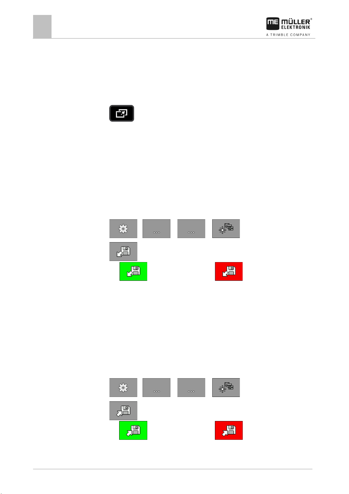
Exporting a configuration
You can export the configuration of your on-board integrated display/controller, to be able to use it
e.g. on a different DRILL-Control.
1. Insert a USB memory device into the on-board integrated display/controller.
2. On the work screen, press:
> > ( ) >
3.
⇨
- Start the export.
- The export was successful or the export has failed.
⇨ If the export was successful, the configuration will be saved as a bin file on the USB memory
device in the "USB-BOX\me-drill-control\export" folder.
Importing a configuration
You can import a configuration from a USB memory device to your DRILL-Control.
1. Save the desired configuration on a USB memory device in the folder: "USB-BOX\me-drillcontrol\import".
2. Insert the USB memory device into the on-board integrated display/controller.
3. On the work screen, press:
> > ( ) >
4.
⇨
- Start the import.
- The import was successful or the import has failed.
5. Restart the on-board integrated display/controller to work with the imported configuration.
Page 47
30283620-02-EN
V2.20191001
47
10.4
Procedure
Using the system functions of the on-board integrated display/controller
Updating the on-board integrated display/controller
10
Updating the on-board integrated display/controller
If a new software version is available for your on-board integrated display/controller, you can update
it.
You have received an update file in zip format from Müller-Elektronik.
1. Unpack the zip file on an empty USB memory device.
2. Insert the USB memory device into the on-board integrated display/controller.
⇨ The software automatically detects that a new software version is saved on the USB
memory device.
⇨ You will be asked whether you want to update the on-board integrated display/controller.
3. Confirm.
⇨ The new software will be installed on the on-board integrated display/controller.
4. Restart the on-board integrated display/controller.
Page 48
48
V2.20191001
30283620-02-EN
Number representing a specific function.
Connected cable core. You can find the
meaning of the abbreviations in this section.
Function icon
Meaning
11
11.1
Troubleshooting
11
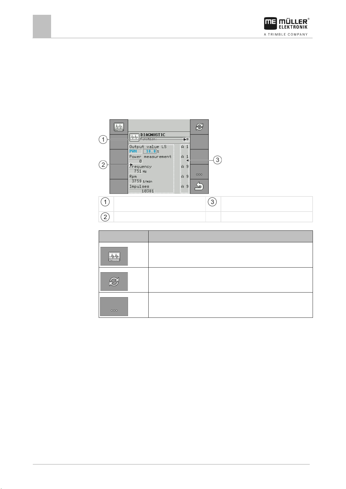
Performing diagnostics
Troubleshooting
Performing diagnostics
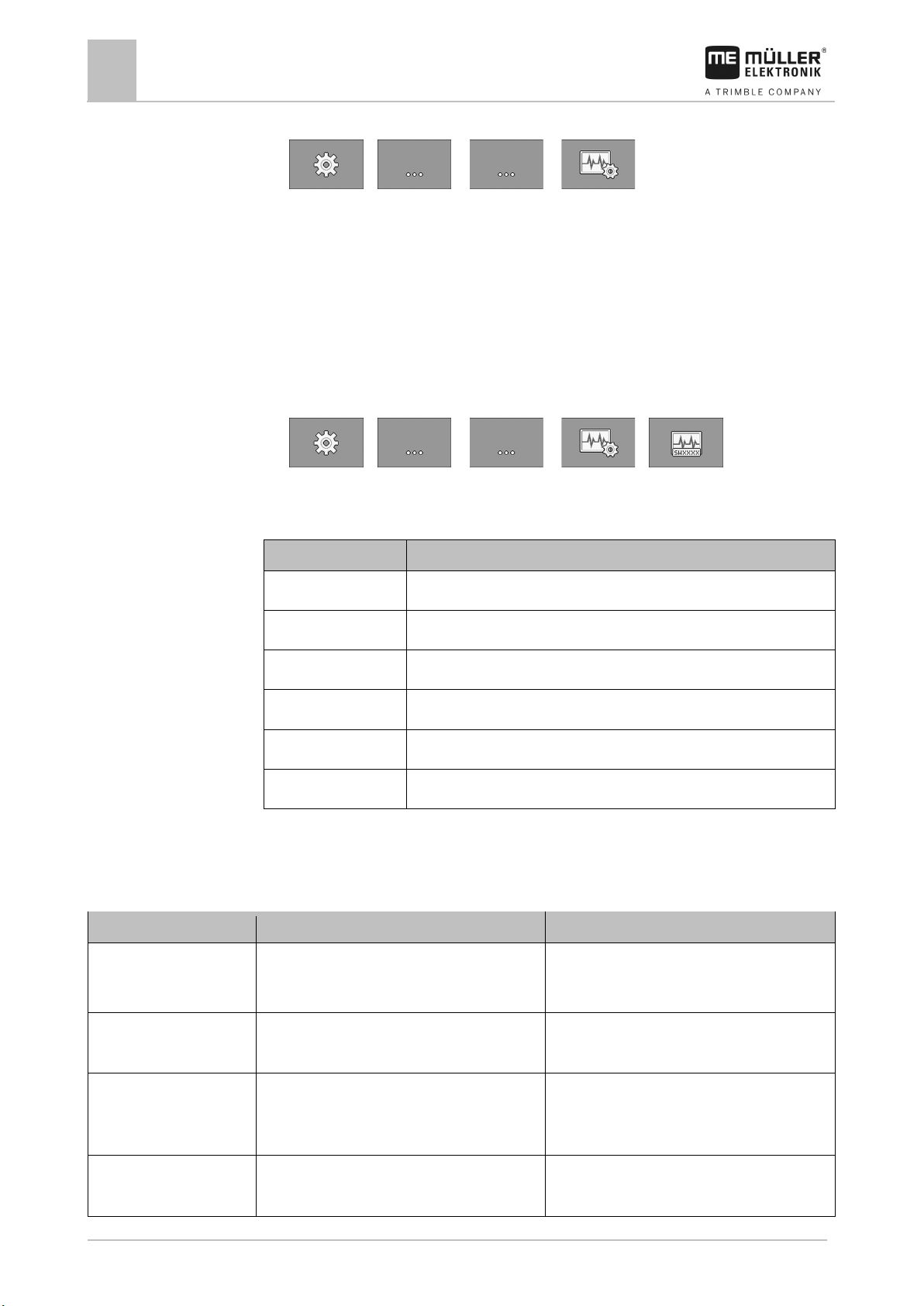
In the diagnostic, you can read the measured values for all of the pins that are connected to the
junction box. In addition, you can test whether the functions of the job computer are working as
desired.
In the diagnostic, you will see the following screen:
Parameters and measured values
Calls up the "Version numbers" screen. [➙ 50]
Sets the current measured values to "0".
Calls up the next function.
The following abbreviations are possible for the cable cores:
▪ "A", "B", "C"
The designations are analogous to the designations in the assignment plan of the junction box.
Depending on the functions of the individual components, the following measured values are
possible:
▪ “Frequency”
Current measured frequency of the function.
▪ “Rpm”
Current measured rpm of the function.
▪ “Impulses”
Current measured number of impulses of the function.
▪ “Analog Value”
Current measured analog value of the function. The analog value always increases or decreases
proportionally.
Example: The higher the position of an analog work position sensor, the higher the analog value.
▪ “Power Measurement”
Page 49
30283620-02-EN
V2.20191001
49
Procedure
Troubleshooting
Performing diagnostics
11
Currently measured current flow of the function. The value of the power measurement always
increases or decreases proportionally.
Example: The faster an electric motor is turning, the higher the value of the power measurement.
▪ “Input”
– “low”
The function is deactivated. There is no voltage at the input.
– “high”
The function is activated. There is voltage at the input.
You can enter the following settings:
▪ “Output Value LS”
– “PWM”
Depending on the entered PWM value, you can test whether an electric or hydraulic motor
is turning at the entered PWM value.
– “Rev.”
Depending on the rpm, you can test how long it takes for an electric or hydraulic motor to
reach the defined rpm.
▪ “Output Value HS”
– “low”
The function is deactivated. There is no voltage at the input.
– “high”
The function is activated. There is voltage at the input.
▪ “Output value HS/LS”
– “low”
The function is activated or deactivated. Depending on how the function is switched, there
either is voltage or not.
– “high”
– The function is activated or deactivated. Depending on how the function is switched, there
either is voltage or not.
▪ “Full Bridge”
With the respective selection, you can test the linear actuators.
– “Stop”
The function is deactivated. The linear actuator is not moving.
– “+/-”
The linear actuator is moving in one direction. The direction in which the linear actuator is
moving depends on the respective connection.
– “-/+”
The linear actuator is moving in one direction. The direction in which the linear actuator is
moving depends on the respective connection.
Seeding is stopped.
Page 50
50
V2.20191001
30283620-02-EN
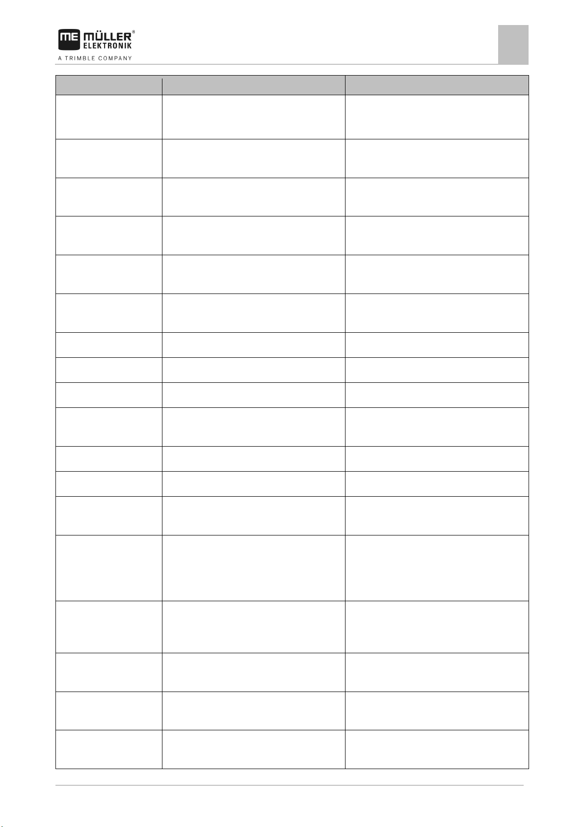
Version number
Meaning
Serial Number
Serial number of the job computer
HW Version
Hardware version of the job computer
SW (initial)
Delivered software version on the job computer
SW (current)
Current software version on the job computer
Pool Version
Version of the pool with texts and images
Hydr. Version
Version of the hydraulic system configuration
Alarm text
Possible cause
Remedial measure
Remediate the cause.
rotating too fast.
cannot work reliably at the current speed.
speed.
range exceeded.
or lower than the set speed.
metering roll.
Procedure
11.2
Procedure
11.3
Troubleshooting
11
Checking the version numbers
1. On the work screen, press:
> > ( ) >
⇨ The “Diagnostic” screen appears.
⇨ On the screen, you can see the measured values and possible settings for the individual
functions.
Checking the version numbers
To check the version numbers, proceed as follows:
1. On the work screen, press:
> > ( ) > >
⇨ The “Version number” screen appears.
⇨ All version numbers are displayed.
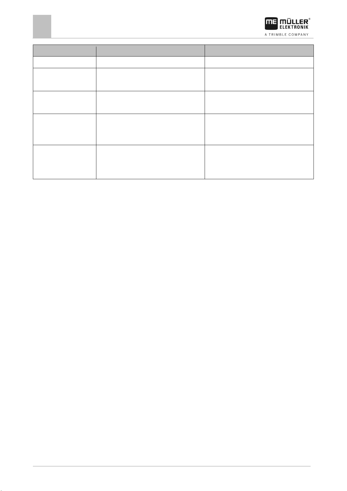
Alarm messages
Overview of the alarm messages
Metering drive is stationary. The current speed of the metering drive is lower
than the minimum speed.
The metering drive is
Metering drive cannot
maintain target rate.
Metering drive regulation
You are driving too fast. The metering drive
You are driving too fast or too slow. It is not
possible to reach the target rate at the current
The current speed of the metering drive is higher
Stop immediately!
Drive more slowly or install a larger metering roll.
Drive more slowly or faster, so that the job
computer can control the target rate.
Drive more slowly or faster or install a larger
Page 51
30283620-02-EN
V2.20191001
51
Alarm text
Possible cause
Remedial measure
Remediate the cause.
the "Min. Rotational Speed" parameter.
Rotational Speed" parameter for the fan.
the "Max. Rotational Speed" parameter.
Rotational Speed" parameter for the fan.
value for the "Maximum Value" parameter.
Value" parameter.
The pressure of a linear sensor is below the value
for the "Minimum Value" parameter.
Value" parameter.
hopper.
Hopper is empty.
There is no more seed or fertilizer in the hopper.
Fill the hopper.
Error in blockage system.
An error has occurred in the blockage system.
Check the blockage system.
Seed flow detected.
Seed flow has occurred in a tramline.
Check the tramline control.
flow.
Input is too high.
The entered value is too high.
Enter a lower value.
Input is too low.
The entered value is too low.
Enter a higher value.
charger.
Raise the implement.
Error with the initialisation of
configuration.
activated.
off.
while a task is activated in
Troubleshooting
Alarm messages
11
Metering shaft is stationary. The revolution sensor on the metering shaft does
not register any movement of the metering shaft.
Fan is rotating too slowly. The current fan speed is lower than the value for
Fan is rotating too fast. The current fan speed is higher than the value of
Pressure is too high. The pressure of a linear sensor exceeds the
Pressure is too low.
Hopper is low. There is not enough seed or fertilizer in the
Stop immediately!
Increase the fan speed or change the "Min.
Decrease the fan speed or change the "Max.
Reduce the pressure or change the "Maximum
Increase the pressure or change the "Minimum
Fill the hopper.
No seed flow detected. The blockage system has not detected any seed
Charger fault. There is a malfunction in the alternator of the
The metering was stopped
The implement is not in working position. Raise the implement.
because the working
position was not reached.
There was an error in the Control Layer
the Control Layer
Right half width is not
Right half width is not shut
configuration.
The right half width is shut off. Activate the right half width.
The right section is activated. Shut off the right half width.
Check the blockage system.
Check the alternator of the charger.
Check the configuration.
Procedure is not allowed
A task is activated in the ISOBUS-TC application. Deactivate the task.
Page 52
52
V2.20191001
30283620-02-EN
Alarm text
Possible cause
Remedial measure
the ISOBUS-TC application.
that is switched off.
has been lost.
memory or EEPROM.
A download manager has been activated.
Troubleshooting
11
Alarm messages
Seed flow detected in a row
Speed signal from CAN bus
Error with the reading or
writing of data to the flash
System has been stopped.
Reboot required.
The row is defective. Check the row.
The cable was disconnected. Check the cable connection.
An error has occurred while the job computer was
Restart the job computer.
starting.
The connection to a slave job computer has been
Reboot the job computer.
interrupted.
Page 53
30283620-02-EN
V2.20191001
53
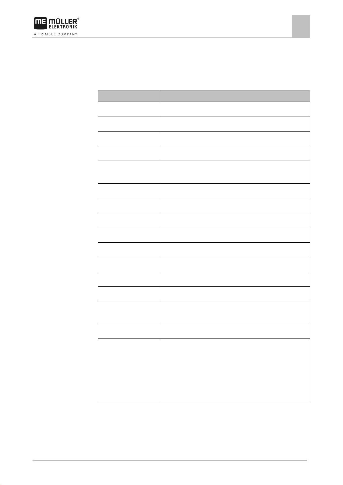
Parameter
Value
Operating voltage
10 -16 V
Operating temperature
-20°C - +60°C
Storage temperature
-30°C - +70°C
Dimensions (W x H x D)
220 x 205 x 90 mm
level 4
ESD protection
In accordance with ISO 10605 Level 4
Protection class
IP 54 (when all plugs are connected)
Power input
0.3A @ 13.6V, without connected sensors and actuators
Display
5.7" TFT QVGA
Processor
72MHz ARM7, 512kB Flash, 64kB RAM
RAM
16MB
Boot USB
32MB
Serial FRAM
-
an external power supply
Keyboard
16 keys plus on/off key, all backlit
periods
12
12.1
Technical specifications
Technical specifications
Technical specifications of the on-board integrated display/controller
12
Technical specifications of the on-board integrated
display/controller
EMC In accordance with ISO 14982 / CISPR25 Interference suppression
Real Time Clock Buffered by capacitor, keeps the time for more than 2 weeks without
Outputs 4 high-side switches with power measurement, max. 5A per high-side
3 full bridges with power measurement max. 10A per bridge
The power specifications only apply if only one high-side or one bridge
is active.
Total power consumption: max. 15A, 20A are permitted for short
Page 54
54
V2.20191001
30283620-02-EN
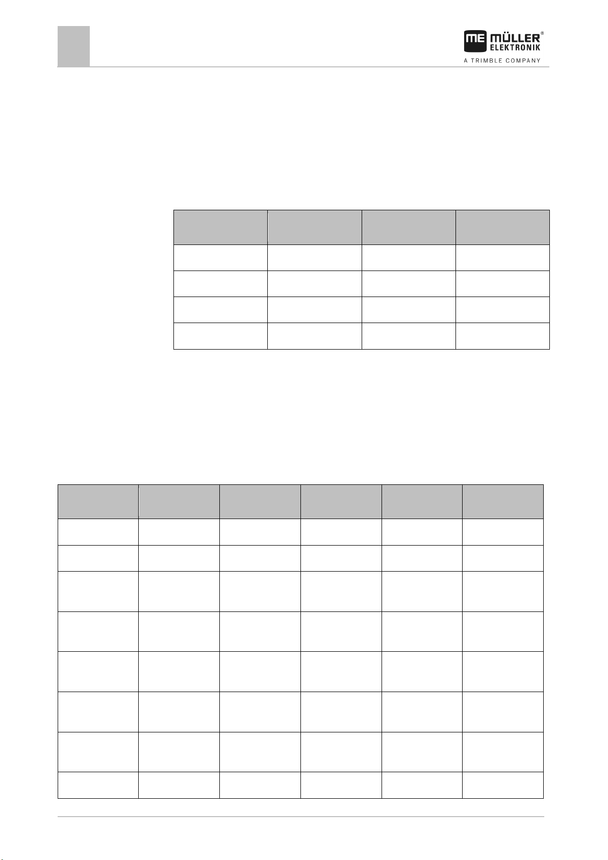
8-pin flange socket
Pin no.
Signal
8-pin flange socket
Pin no.
Signal
1
Pulses per 100 meters
5
Work position sensor
2
V sensor
6
Radar sensor
3
0VE
7
RS232 RxD
4 8
RS232 TxD
39-pin connector
Pin no.:
Signal
39-pin connector
Pin no.:
Signal
39-pin connector
Pin no.:
Signal
A1
Metering drive +
B1
Metering drive +
C1
CAN_H
A2
Metering drive -
B2
Metering drive -
C2
CAN_L
+/-
+/-
/+
/+
+/-
+/-
-/+
-/+
emergence marker
marker
A8
Metering shaft
B8 C8
0VL
12.2
12.2.1
12.2.2
Technical specifications
12
Connector pin assignment
Connector pin assignment
8-pin flange socket
These abbreviations are used in the following table:
▪ VE – Electronics voltage
▪ VL – Power voltage
39-pin multipole connector
These abbreviations are used in the following table:
▪ VE – Electronics voltage
▪ VL – Power voltage
▪ A – Series A
▪ B – Series B
▪ C – Series C
A3 Tramline valve left
A4 Tramline valve left -
A5 Tramline valve right
A6 Tramline valve right
A7 0VE B7 Radar sensor C7 Left pre-emergence
B3 Tramline valve left
B4 Tramline valve left -
B5 Tramline valve right
B6 Tramline valve right
C3 Left bout marker
C4 Right bout marker
C5 0VL
C6 Right pre-
Page 55
30283620-02-EN
V2.20191001
55
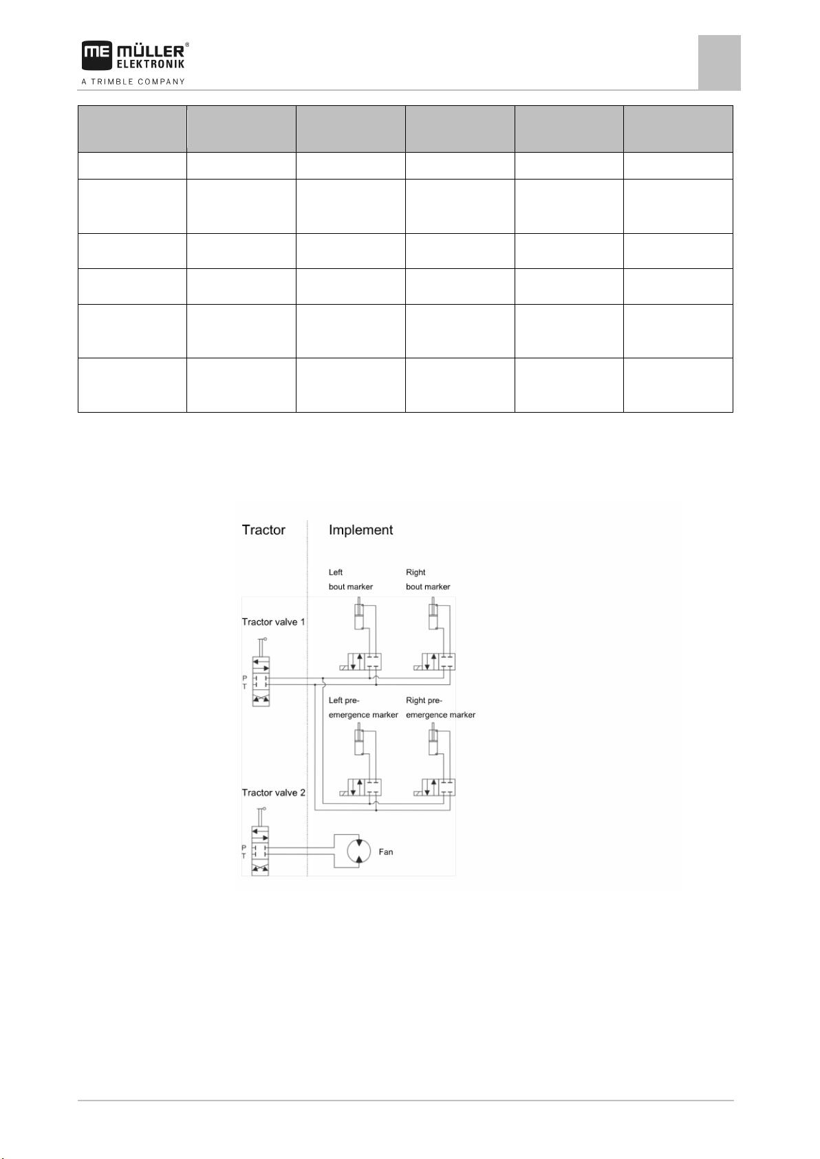
Pin no.:
Pin no.:
Pin no.:
speed sensor
sensor
A10 B10 C10
Fan speed sensor
A11
Lower level sensor
B11
Upper level sensor
C11
sensor
supply
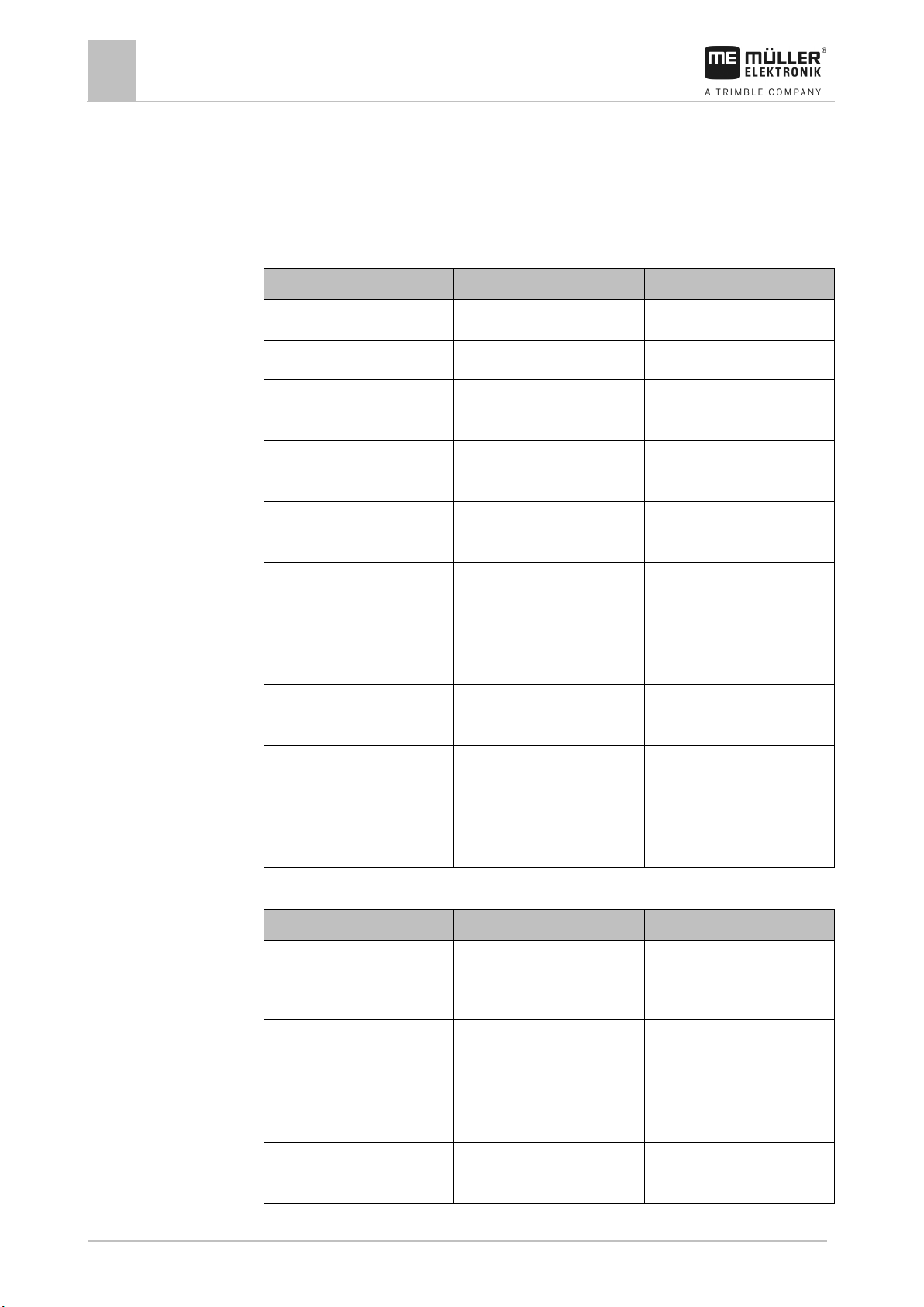
12.3
Technical specifications
Hydraulic system of the implement
12
39-pin connector
A9 Engine speed
Signal 39-pin connector
B9 12VE C9
Signal 39-pin connector
Signal
A12 Calibration switch B12 C12 Work position
A13 B13 Potentiometer
C13 V-Namur
Hydraulic system of the implement
The following figures show the standard hydraulic system of the implement:
Page 56
56
V2.20191001
30283620-02-EN
German
English
Explanation
0VE or GNDE
0VE or GNDE
0V for sensors
12VE
12VE
12V for sensors
calibration button is switched.
implement is in working position
seed in a hopper.
seed in a hopper.
speed of a metering drive.
speed of a fan.
speed of a metering shaft.
speed.
German
English
Explanation
0VL or GNDL
0VL or GNDL
0V for actuators
12VL
12VL
12V for actuators
metering unit with energy.
marker.
emergence marker.
13
Explanation of the signals in the pin-out diagram
13
Explanation of the signals in the pin-out diagram
There is an pin-out diagram for each implement model. You can obtain the pin-out diagram
corresponding to your implement from your contact person at Müller Elektronik.
In the next tables, you will find explanations for the texts that are found on the pin-out diagram.
Glossary – Input signals
Calibration button Calibration button Sensor that checks if the
Work position sensor Work position sensor Sensor that checks if the
Upper level sensor Upper level sensor Sensor that checks if there is
Lower level sensor Lower level sensor Sensor that checks if there is
Metering drive speed sensor Metering drive speed sensor Sensor that measures the
Fan speed sensor Fan speed sensor Sensor that measures the
Metering shaft speed sensor Metering shaft speed sensor Sensor that measures the
Vehicle speed sensor Vehicle speed sensor Sensor that measures the
Glossary – Output signals
Metering Drive Metering drive Actuator that supplies the
Bout marker Bout marker Actuator that controls the bout
Pre-emergence marker Pre-emergence marker Actuator that controls the pre-
Page 57
30283620-02-EN
V2.20191001
57
German
English
Explanation
tramline.
the calibration flap.
Explanation of the signals in the pin-out diagram
13
Tramline Tramline Actuator that closes the
Calibration flap Calibration flap Actuator that opens and closes
Page 58

58
V2.20191001
30283620-02-EN
14
14
Notes
Notes
 Loading...