

Page 1

YaRD-MaN)//
Operator's Manual
21" Self Starter
Rear-Discharge
Lawn Mower
Model Series
IMPORTANT: Read safety rules and instructions carefully before operating equipment.
Warning: This unit isequipped withan internalcombustionengine andshould not be used on or near any unimproved forest-
covered, brush-coveredor grass-covered land unlessthe engine's exhaust system is equipped witha spark arrester meeting
applicable local or state laws (ifany). If a spark arrester is used, it should be maintainedin effective working order by the operator.
In the State of Californiathe above isrequiredbylaw (Section4442 ofthe California Public Resources Code). Other states may have
similar laws. Federal laws apply onfederal lands.A sparkattester for the muffler is available throughyour nearest engine authorized
service dealer or contact the service department, P.O. Box 368022 Cleveland, Ohio 44136-9722.
MTD PRODUCTS INC. P.O. BOX 368022 CLEVELAND, OHIO 44136-9722
ECO#
PRINTED IN U.S.A.
FORM NO. 770-10478.fm
(1/2001)
Page 2
TABLEOFCONTENTS
Content Page
ImportantSafe OperationPractices ................................................................... 3
Slope Gauge...................................................................................................... 6
Unpacking .......................................................................................................... 7
Assembling Your Lawn Mower ........................................................................... 7
Know Your Lawn Mower .................................................................................... 10
Operating Your Lawn Mower ............................................................................. 10
Maintaining Your Lawn Mower ........................................................................... 13
Servicing Your Lawn Mower .............................................................................. 14
Making Adjustments .......................................................................................... 16
Off- Season Storage .......................................................................................... 17
Troubleshooting ................................................................................................. 18
Parts List............................................................................................................ 20
FINDINGMODELNUMBER
This Operator'sManual is an important part of your newLawn Mower. Itwill helpyou assemble, prepare
and maintain the unit for best performance. Please readand understand what it says.
Before you start assembling your new equipment, please locate the model plate onthe
equipmentand copythe informationfromit inthe space providedbelow.The informationon
the model plateisvery importantif youneedhelpfromourCustomerSupportDepartmentor
an authorized dealer.
You can locatethe model numberby standingbehind the unitinthe operatingposition and looking
down at the rear of the deck. A sample model plate is explained below. For future reference, please
copy the modesnumber and the serial number of the equipment in the space below.
Copy the model number here:
Copy the serial number here:
CALLINGCUSTOMERSUPPORT
Ifyou have difficulty assemblingthis product or have anyquestions regardingthe controls, operationor
maintenance of this unit, please call the Customer Support Department.
Call 1- (330) 220-4MTD (4683) or 1- (800)-800-7310 to reach a Customer Support
representative,Please haveyourunit'smodelnumberand serial number readywhenyou
call.See previoussectiontolocatethisinformation,You will be askedto enterthe serial
numberinordertoprocessyourcall.
2
Page 3
SECTION1: IMPORTANTSAFEOPERATIONPRACTICES
WARNING: This symbol pointsout importantsafety instructionswhich, if not followed, couldendanger
the personalsafetyand/or propertyofyourselfandothers. Read and followallinstructionsinthismanual
beforeattemptingto operatethismachine.Failuretocomplywiththeseinstructionsmay resultin personal
injury.Whenyou see thissymbol--HEED ITSWARNING.
WARNING: Engine exhaust, some of itsconstituents,and certainvehicle componentscontainor emit
chemicalsknowntoStateof Californiatocausecancerand birthdefectsor otherreproductiveharm.
WARNING: Thismachine was builtto beoperated accordingto the rulesfor safe operationinthis manual.As with
any type of power equipment, carelessness or error on the part of the operator can result in sedous injury. This
machine is capable of amputating hands and feet and throwing objects. Failure to observe the followingsafety
instructionscould result in sedousinjuryor death.
GeneralOperation
1. Read this operator's manual carefully in its entirety
before attempting to assemble this machine. Read,
understand, and follow all instructions on the machine
and in the manual(s) before operation. Ba completely
familiar with the controls and the proper use of this
machine before operating it. Keep this manual in a safe
place for future andregular reference andfor ordedng
replacament parts.
2. This machine is a precision piece of power equipment,
not aplaything. Therefore, exercise extreme caution at all
times. Your unithasbeen designedto performonejob: to
mow grass.Do notuse itfor any other purpose.
3. Never allow childrenunder 14 years oldtooperate this
machine. Children 14years oldand overshouldread and
understandthe operation instructionsandsafety rulesin
this manual and shouldbe trained and supervisedbya
parent,Only responsibleindividualswhoare famUiarwith
these safe operationrulesshoulduse thismachine.
4. Thoroughlyinspectthe area where the equipment isto
be used. Remove all stones,sticks,wire,bones,toys and
otherforeign objectswhichcould be tdppedoveror
pickedup andthrown bythe blade. Thrown objectscan
cause sehous personalinjury.Plan your mowingpattern
to avoiddischargeofmatedal toward reeds, sidewalks,
bystandersand the like. Also, avoid dischargingmatedal
againstawallorobstructionwhich may cause discharged
matedal to ricochetbacktowardthe operator.
5. To help avoid blade contact or a thrown objectinjury,stay
inthe operatorzone behind the handles and keep
bystanders,helpers,childrenand pets at least75 feet
from the machine while itisin operation. Stop machine if
anyone enters the area.
6. Always wear safetyglassesor safety goggles during
operationandwhile performingan adjustmentorrepairto
protectyoureyes. Thrownobjects which dcochetcan
cause sedous injurytothe eyes.
7. Wear sturdy, rough-soledworkshoesand close-fitting
slacksand shirts.Shirtsand pants thatcover the arms
and legsand steel-toedshoes are recommended. Never
operate this machine inbare feet, sandals,slipperyor
lightweight (e.g. canvas) shoes.
8. Do notputhandsorfeet near rotatingpartsor underthe
cuttingdeck. Contactwiththeblade can amputatehands
and feet.
9. A missingor damaged dischargecover can cause blade
contact or thrownobject injudes.
10. Manyinjuriesoccuras a resultofthe mowerbeing pulled
overthe footdudog a fall caused byslippingortripping.
Do not holdon to the mower ifyou are falling; release the
handleimmediately.
11. Neverpullthemower backtowardyouwhile you are
walking. If you mustbackthe mowerawayfroma wail or
obstructionfirstlookdown and behind to avoid tripping
and then followthese steps:
a. Step backfrom the mower tofully extend your
alTRS,
b. Be sureyou are well balancedwithsurefooting.
c. Pullthemowerbackslowly,nomorethan halfway
towardyou.
d. Repeat these stepsas needed.
12. Donotoperate the mower whileunder the influenceof
alcoholor drugs.
13. Do notengage the self-propeUedmechanism onunitsso
equippedwhilestartingengine.
14. The blade control handle isa safetydevice, Never
attemptto bypassitsoperation.Doingso makesthe
safety device inoperativeandmay resultinpersonal
injury throughcontact withthe rotatingblade.The blade
controlhandlemustoperate easily inboth directionsand
automaticallyreturnto the disengagedposition when
released.
15. Never operatethe mowerinwet grass.Always be sureof
yourfooting. A slip andfall can cause seriouspersonal
injury.Ifyoufeel you are losingyourfooting, releasethe
blade controlhandle immediately and the bladewillstop
rotatingwithinthreeseconds.
16. Mow in daylightorgood artificiallight.Walk, never ran.
17. Stop the blade when crossinggraveldrives,walkways
orroads.
18. If the equipment shouldstart to vibrate abnormally, stop
the engine and check immediately for the cause.
Vibration isgenerally a warning of trouble.
19. Shut the eogine off and wait untilthe blade comes to a
completestop before removing the grass catcher or
unclogging the chute. The cutting blade continues to
rotate for a few seconds after the engine is shut off.
Never place any part of the body in the blade area until
you are sure the blede has stopped rotating.
Page 4
20. Never operate mowerwithoutpreper trail shield, 5.
discharge cover, grass catcher, blade control handle or
other safety protective devices in place and working. 6.
Never operate mower with damaged safety devices.
Failure to do so, can result in personal injury.
21. Muffler and engine become hot and can cause a bum. Do
not touch.
22. Only use parts and accessories made forthis machine by
the original equipment manufacturer(O.E.M). Failureto Service
do so can result in personal injury.
23. Ifsituations occur which are not covered in this manual,
use care and good judgment. Contact your dealer for
assistance.Telephone 1-800-800-7310 for the name of
your nearest dealer.
SlopeOperation
Slopes are a major factor related to slipandfall accidents
whichcan resultin severe injury.Operationon slopes
requiresextra caution.Ifyou feel uneasy on aslope, donot
mow it.Before operating thisunit on a slope orhillyarea, use
the slopegaugeon page 6to measure slopes. Ifthe slope is
greaterthan 15 degrees, do not mow it.
Do:
1. Mow acrossthe face ofslopes; neverup and down.
Exercise extreme caution when changingdirection on
slopes.
2. Watchfor holes,ruts,rocks,hiddenobjects, or bumps
whichcan cause you toslipor tdp.Tall grass can hide
obstacles.
3. Always be sureofyour fuofing. A slipandfall can cause
seriouspersonal injury.If youfeel youare losingyour
balance, releasethe bladecontrolhandle immediately,
andthe bladewillstoprotatingwithin3 seconds.
DoNot:
1. Do not mow neardrop-offs,ditchesor embankments,
you could loseyourfooting or balance.
2. Do not mow slopssgreater than 15 degreesas shownon
the slope gauge.
3. Do notmowon wet grass. Unstablefootingcould cause
slipping.
Children
Tragic accidentscan occur if the operator is not alerttothe
presence of children.Children are often attractedtothe
mowerand the mowingactivity.They do not understandthe
dangers. Never assume that childrenwillremainwhere you
lastsaw them.
1. Keep childrenoutofthe mowing area and underthe
watchfulcare of a responsibleadultotherthanthe
operator.
2. Be alert and turn mower off ifachildentersthe area.
3. Before and whilemoving backwards, look behindand
downfor smallchildren.
4. Use extreme carewhen approachingblindcomers,
doorways,shrubs,trees, orotherobjectsthat may
obscureyourvisionofa childwho may runintothe
mower.
Keep childrenaway from hotor running engines. They
can suffer bums from a hot muffler.
Never allow children under 14years old to operate a
power mower. Children 14 years old and over should
read and understand the operation instructions and
safety rules in this manual and should betrained and
supervised by a parent.
SafeHandlingof Gasoline:
1. To avoid personal injury or property damage use extreme
care in handling gasoline. Gasoline is extremely
flammable and the vapors are explosive.Sedous
personal injury can occur when gasoline is spilled on
yourself or your clothes which can ignite.
2. Wash your skinandchange clothes immediately.
3. Use only an approvedgasoline container.
4. Never fill containersinside a vehicle or on a truck or
trailer bedwith aplastic liner. Always place containers on
the ground away from your vehicle before filling.
5. If possible, remove gas-powered equipment from the
truck or trailer and refuel it on the ground. If this is not
possible, then refuel such equipmenton a trailer with a
portable container, rather than from agasoline dispenser
nozzle.
Keep the nozzle incontact with the dm of the fuel tank or
container opening atall times until fueling iscomplete.Do
not use a nozzle lock-open device.
Extinguish all cigarettes, cigars, pipes and other sources
of ignition.
Never fuel machine indoors because flammable vapors
will accumulate inthe area.
Never remove gas cap or add fuel while the engine is hot
or running. Allow engine to cool at least two minutes
before refueling.
Never over fill fuel tank. Fill tank to no more than ½ inch
below bottom offiller neck to providespace for fuel
expansion.
Replace gasoline cap and tighten securely.
Ifgasoline is spilled, wipe itoff the engine and
equipment. Move unit to another area. Wait 5 minutes
before starting the engine.
Never store the machine or fuel container inside where
there is an open flame, spark or pilot light as on a water
heater, space heater, furnace, clothes dryer or other gas
appliances.
14. To reduce fire hazard, keep mower free of grass, leaves,
or other debds build-up. Clean up oil or fuel spillage and
remove any fuel soaked debds.
15. Allow a mower to cool at least 5 minutes before storing.
GeneralService:
6,
7.
8.
9.
1(3.
11.
12.
13.
1. Never runan engine indoorsorina poody ventilated
area. Engine exhaust containscarbon monoxide,an
ododessand deadly gas.
2. Before cleaning, repairing,orinspecting,makecertain
the blade and all movingparts have stopped. Disconnect
the sparkplugwireand groundagainstthe engineto
prevent unintendedstarting.
Page 5
3. Check the blade and engine mounting bolts at frequent
intervals for proper tightness. Also, visually inspect blade
for damage (e.g., bent, cracked, worn) Replace blade
with the original equipment manufacture's (O.E.M) blade
only, listed in this manual. "Use of parts which do not
meet the original equipment specifications may leadto
improper performance and compromise safety!"
4. Mower blades are sharp and can cut. Wrap the blade or
wear gloves, and use extra caution when servicing them.
5. Keep allnuts, bolts, and screws tight to be sure the
equipment is in safe working condition.
6. Never tamper with safety devices. Check their proper
operation regulady.
7. After sthking aforeign object, stop the engine, disconnect
the spark plug wire and de-energize the starter. (See
section "To De-energize Self Starter". Thoroughly inspect
the mower for any damage. Repair the damage before
starting and operating the mower.
8. Never attempt to make awheel or cutting height
adjustment while the engine is running.
9. Grass catcher components, discharge cover, and trail
10.
11.
12.
13,
shield are subjectto wearand damage whichcould
expose moving parts or allowobjects to be thrown.
For safety protection, frequently check components and
replace immediately with odginal equipment
manufacturer's (O.E.M.) parts only, listed in this manual.
"Use of parts which do not meet the odginal equipment
specifications may lead to improper performance and
compromise safety!"
Do not change the engine governor setting oroverspeed
the engine. The governor controls the maximum safe
operating speed of the engine.
Maintain or replace safety and instruction labels, as
necessary.
Observe properdisposallawsand regulations.Improper
disposal of fluidsand materials can harmthe
environment.
ALWAYS de-energize self starter priorto performingany
maintenance or servicetothe engine and or mower,
Followinstructionsboth in the manualand on the engine
and ormachine to de-enen:jizestarter.
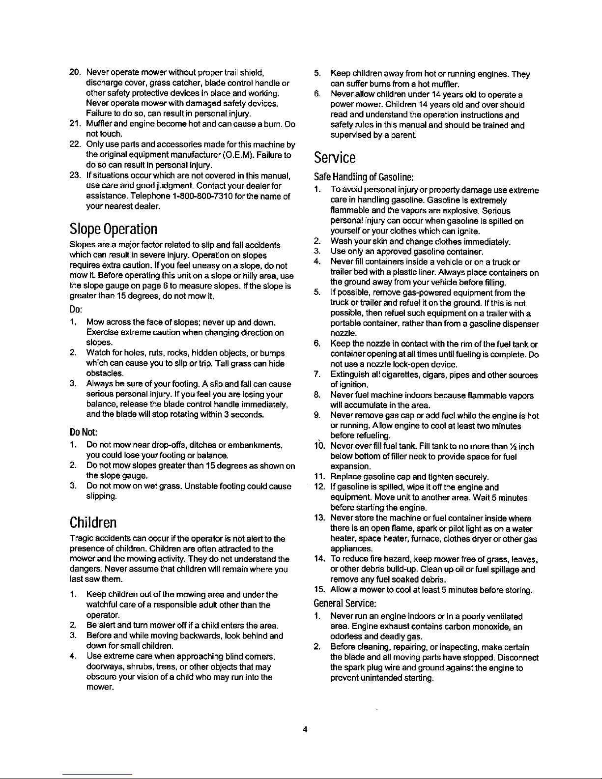
YourResponsibility
Restrict the use of this power machine to persons who read, understand and follow the warnings and instructions in
this manual and on the machine.
DANGER
5
Page 6
9
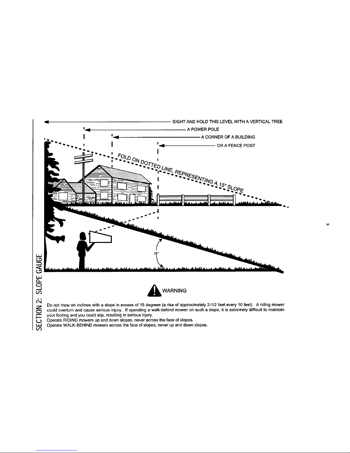
SIGHT AND HOLD THIS LEVEL WITH A VERTICAL TREE
A POWER POLE
A CORNER OF A BUILDING
OR A FENCE POST
15°
Q_
° A
o_ WARNING
Do not mow on inclines with a slope in excess of 15degrees (a rise of approximately 2-1/2 feet every 10 feet). A riding mower
Z
O could overturn and cause serious injury. If operating a walk-behind mower on such a slope, it is extremely difficult to maintain
your footing and you could slip, resulting in serious injury.
Operate RIDING mowers up and down slopes, never across the face of slopes.
(_f) Operate WALK-BEHIND mowers across the face of slopes, never up and down slopes.
Page 7
SECTION3: UNPACKING
RemovingUnitFromCarton
Remove staples, break glue on top flaps or cut tape
at carton end and peel along top flap to open
carton.
Remove loose parts if included with unit (i.e.,
operator's manual, hardware pack etc.).
Cut corners andlay cartondown flat.Remove
packing material.
Roll orslideunitout ofcarton.Check carton
thoroughlyfor looseparts.
SECTION4: ASSEMBLINGYOURLAWNMOWER
NOTE; Make sure not to crimp the cables while
removing the loose parts or the entire unit from the
carton.
NOTE: Reference to rightor left hand sideof the mower
isobserved from the operating position.
Tools Required
PairofPliers
Funnel
Set ofadjustablewrenches
WARNING: Disconnect the spark plug
wire and ground it against the engine to
preventunintendedstarting.Leave safety key
in lockedposition.
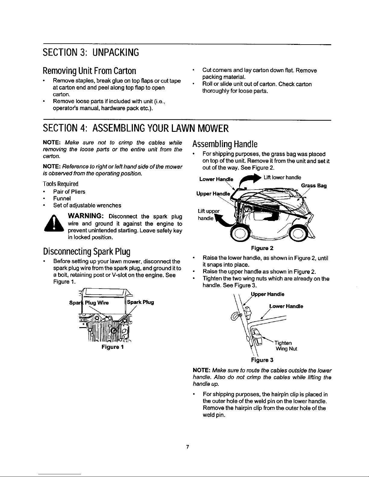
DisconnectingSparkPlug
Before setting up your lawn mower, disconnect the
spark plugwire fromthe spark plug, and ground itto
a bolt, retaining post or V-slot on the engine. See
Figure 1.
Spark Plug
Figure 1
AssemblingHandle
For shipping purposes, the grass bag was placed
on top ofthe unit. Remove it from the unit andset it
out of the way. See Figure 2.
Lift lowerhandle
GrassBag
UpperHandle
Liftu
handle
Figure 2
Raise the lower handle, as shown inFigure 2, until
it snaps into place.
Raise the upper handle as shown in Figure 2.
Tighten the two wing nuts which are already on the
handle. See Figure 3.
UpparHandle
LowerHandle
n
Nut
Figure 3
NOTE: Make sureto route thecables outside thelower
handle. Also do not crimp the cables while lifting the
handle up.
Forshipping purposes, the hairpin clip is placed in
the outer hole of the weld pin on the lower handle.
Remove the hairpin clip from the outer hole of the
weld pin.
Page 8
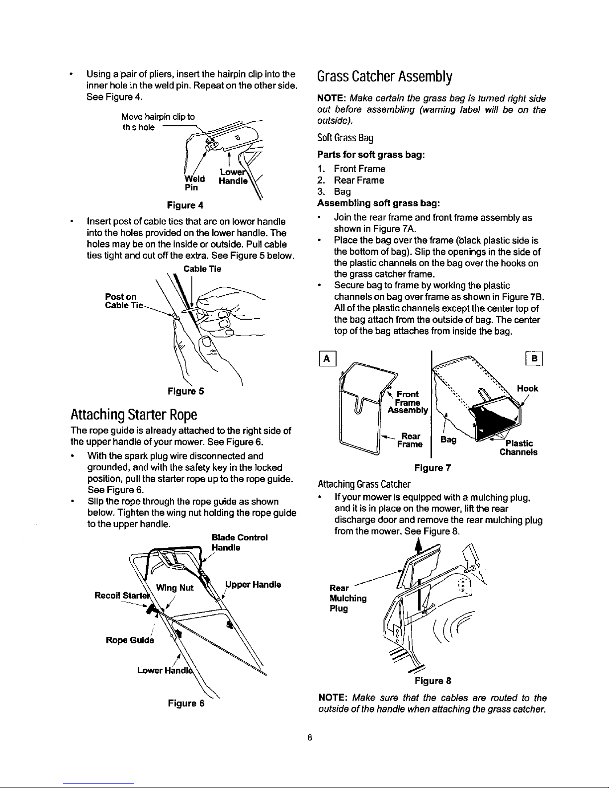
Usinga pair of pliers, insert the hairpin clip into the
inner hole inthe weld pin. Repeat on the other side.
See Figure 4.
Move hairpin clipto
this hole --
f
Weld Handle
Pin
Figure 4
Insertpost ofcable tiesthat are on lower handle
into the holes provided on the lower handle. The
holes may be on the inside or outside. Pull cable
ties tight and cut offthe extra. See Figure 5below.
Cable Tie
Post on
Figure 5
Attaching Starter Rope
The rope guide is already attached to the right side of
the upper handle ofyour mower. See Figure 6.
With the spark plug wire disconnected and
grounded, and with the safety key in the locked
position, pull the starter ropeup to the rope guide.
See Figure 6.
Slip the rope through the rope guide as shown
below. Tighten the wing nut holding the rope guide
to the upper handle.
BladeControl
Handle
GrassCatcherAssembly
NOTE: Make certain the grass bag is tumed fight side
out before assembling (warning label will be on the
outside).
SoffGrass Bag
Parts for soft grass bag:
1. Front Frame
2. Rear Frame
3. Bag
Assembling soft grass bag:
Jointherear frame and front frame assemblyas
showninFigure7A.
Place thebag over theframe (blackplasticsideis
the bottomofbag).Sliptheopeningsintheside of
the plasticchannelsonthe bagover thehookson
the grasscatcherframe.
Secure bagto frame byworkingthe plastic
channelsonbagoverframe asshowninFigure 7B.
All ofthe plasticchannelsexceptthecentertopof
the bag attachfrom the outsideof bag.The center
top ofthe bag attaches from insidethe bag.
[] []
Front Hook
rame
sembly
Rear
Frame Plastic
Channels
Figure 7
AttachingGrassCatcher
Ifyour moweris equipped witha mulchingplug,
and it is in place on the mower, lift the rear
discharge door and remove the rear mulching plug
from the mower. See Figure 8.
Recoil
Rear
Mulching
Plug
RopeGude
Figure 6
Figure 8
NOTE: Make sure that the cables are muted to the
outside of the handle when attaching the grass catcher.
Page 9

Liftthe rear discharge door.
Place the hooks of the grass catcher into the slots
in the handle bracket assemblies on both sides.
See Figure 9. Release the rear discharge door.
Figure 9
RemovingGrassCatcher
Lift the rear discharge door on the mower.
Lift the grass catcher up, out of the slots in the
handle bracket assemblies.
Reinstall the plastic rear mulching baffle.
Release the rear discharge door.
WARNING: Never operate the mower
unless the hooks on the grass catcher are
seated in the slots on the handle bracket
assemblies, and the rear discharge door
rests firmly against the top of the grass
catcher.
ChuteDeflector(ifequipped)
If your mower is equipped with the chute deflector,
assemble asfollows:
Rod
Chute
Slide the rod intothe upper edge of the chute
deflector so the tab on the rod is toward the leftside
of the chute deflector. When assembled correctly,
the rod will extend further to the ]eftsidethan the
right side. See Figure 10.
Slide the push nut onto the right side of the rodto
secure.
AttachingChuteDeflector
Lift the rear discharge door on the mower.
Placethe ends of the rod into the slots in the handle
bracket assemblies. See Figure 11.
Release the rear discharge door.
/ Rear
Discharge
_ ,,/ - Door
HandleBracket
Assemblies
Figure 11
Convertingto Mulcher
Liftthe rear discharge door.
Removethe grass bag orchute deflector.
Insert the mulch plug. See Figure 8.
Release the rear discharge door. See Figure 9.
Push
Nut
Figure 10
Page 10

SECTION5: KNOWYOURLAWNMOWER
WARNING: Be familiar with all controls
dl&
and theirproperoperation. Knowhow tostop
the machineanddisengagethem quickly.
DriveControl BladeControlHandle
Start Control Button
Recoil
Starter Upper Handle
Lower Handle
Grass Bag
Rear Discharge Door
Cutting Height
Adjustment
Figure 12
RecoilStarter
The recoil starterhandle is attached to the upper
handle. See Figure12. The recoilstarterisusedto start
the engine when theselfstarterisin thede-energized
mode.
Primer
The primer isusedto pump gas intothecarburetor.Use
it to assist in starting e cold engine, but do not use it
when restarting a warm engine after a short shutdown.
Refer to engine manual for location of the primer.
BladeControlHandle
The blade controlhandleis located onthe upper handle
ofthe mower. The blade controlhandleand starter
controlbuttonmust bedepressedin ordertooperate
the unit.Release the bladecontrolhandleto stopthe
engine andthe bladeandto energizethe self starter.
WARNING: The blade controlhandle is a
safety device. Never attempt to bypass its
operations. Doing so, may result in personal
injurythroughcontactwith the rotatingblade.
The blade rotates whenever the engine is
running and when the self starter is de-
energized.
DriveClutchControl
The ddve control lever is located on the upper handle
and is used to engage the drive. Squeeze the lever
against the upper handle to engage the drive; release
the drive control lever toslow down or stop the mower
from propelling.
SafetyKey
The safety key is located on the engine. See Figure 12.
The safety key is a safety device used to activate and
deactivate the self starter system. The self starter
system will not work without the key in its proper
position. See engine manual for further information
pertaining to the safety key.
NOTE: The safety key must be in the run position to
start the mower for both systems, either the self starter
or recoil starter.
StartControlButton
The startcontrol buttonislocatedon theupper leftside
of the handle. See Figure 12.The start control button
must be depressed fully while pulling the blade control
handle toward the upper handle for the engine to start.
The startercontrolbuttonwillautomaticallyreturntothe
off/up position once the blade control handle is
released,
NOTE: The starterbutton must be depressed to start
the engine with either the serf starter or recoil starting
system.
SECTION6: OPERATINGYOURLAWN
WARNING: Read, understand, and follow
all instructions and warnings on the machine
and inthis manual before operating.
Keep hands and feet away from the discharge area on
and from underthe cutting deck. See safety labels on
page 5.
MOWER
The operationof anylawn mowercan resultinforeign
objects being thrown into the eyes, which can result in
severe eyedamage. Always wear safety glasses oreye
shields.
NOTE: For bestresults raise the cutting position until it
is determined whichheight is best for your lawn. See
CuttingHeightAdjustment Section.
lO
Page 11

GasandOilFill-Up
WARNING: Use extreme care when
handling gasoline. Gasoline is extremely
flammable and the vapors are explosive.
Never fuel machine indoors or while the
engine is hot or running. Extinguish
cigarettes,cigars,pipes,and othersourcesof
ignition.
Service the engine withgasoline and oilas
instructedinthe separate engine manualpacked
with your mower. Readthe instructions carefully.
BeforeStartingMower
,_ WARNING: Read, understand,and follow
all instructionsandwarnings onthe machine
and inthismanualbefore operating.
Attach spark plug wire to spark plug. Make certain
the metalcap onthe end ofthe sparkplug wire
(insidethe rubberboot)isfastened securelyover
the metal tiponthe sparkplug.
Checkthe driveclutchcontrolfor proper
adjustment.If the mower does notpropelitselfor
the drivewheelshesitatewiththe driveclutch
engaged,performthedriveclutchcontrol
adjustmentas instructed on page 16.
FirstTime Starting Engine
NOTE: Use recoil starter rope to start engine for the
very firsttime. Themower isshipped withthesafetykey
in the locked position and the self starter in the de-
energized mode,followinstructionsas follows.
1. Place lawn mower on a levelsurfaceoutdoors.
2. Remove clear plasticpackagingunderfuelcap.
3. Check oillevel.
4. Add fuel.
5. Open shutoffvalve (ifequipped) 1/4turn.
6. Pushsparkplugwire firmlyonspark plug.
7. Turn safetykey 1/4turnclockwiseto RUN position.
8. Make surethatthe driveclutchcontrolis adjusted
sothe drive beltisasloose as possible.
9. Pushthe primerthree times.
10. While standinginthe operatingposition,depress
the startercontrolbuttonfullywiththe thumbof
yourrighthand.
11. Usingyourleft hand, pullthe blade controlhandle
all theway towardthe upperhandle.See Figure13.
12. Release the button.
13. Graspthe recoilrope starterhandlewithyour right
handand slowlypulltowards youuntilfeel a slight
resistance,then pullfirmly untilyourarmis fully
extended.
14. If engine does not start by the second pull, repeat
steps 8, 9,10, 11and 12.
SecondTimeStartingEngine
NOTE: Follow these instructions if the self starter is
already in the energizedmode.
WARNING: NEVER assume starter is in
the de-energized mode, even if the key is in
the locked positionand/or removed from the
engine.ALWAYS de-energize starterpriorto
performinganymaintenanceorservicetothe
engine and/or mower. Follow instructionson
the engine and/ormachinetode-energize.
Blade Control Handle
Starter Control Button
Figure 13
1. Checkoillevel andadd fuel, ifnecessary.
2. Open shutoffvalve (ifequipped)1/4 turn.
3. Turn safetykey 1/4 turnclockwiseto RUN position.
4. Firmlypushprimerbulb 3 times(fora coldengine
only!).
5. While standing at the upper handle, depress the
starter control button with the thumb of your right
hand.
6. Using your lefthand, pull the blade control handle
all the way toward the upper handle. See Figure 13.
Starter will de-energize and engine will start.
(NOTE: if engine does not start, release the blade
control handle andfollow steps 8, 9, 1O,11 and 12
in the "First Time Starting Engine instructions.
NOTE: If any problems are encountered, refer to the
Trouble Shooting Guide for helpful information.
ToStopEngineandBlade
WARNING: The blade will continue to
rotate for three seconds after the blade
controlleverisreleased.
1. Release safetyblade controlhandle (the start
controlbuttonwillautomaticallyreturntothe off/up
position),engineand bladewillstopwithina few
seconds.
11
Page 12

NOTE; Engine may stop with a racketing sound. This
sound isthe serf starterbeing reactivated/energizedfor
thenextstart.
2. Turn safety key 1/4turn counterclockwiseto LOCK
position. Remove key and store ina safe place.
ToDe-EnergizeSelfStarter
Remove spark plug wire from spark plug.
Turn safety key to RUN position (1/4 turn
clockwise).
While standing in the operating position, depress
the starter control button fully with the thumb of your
dght hand.
Using your left hand, pull the control handle all the
way toward the upper handle. (Release button and
wait until blade and starter stop rotating.)
Release safety blade control handle (the start
control button will automatically return to the off/up
position).
Remove safety key.
NOTE: Engine will crank over upon actuating
equipment startingcontrols, but willnot spark if spark
plug wire was removed from spark plug as described
above. Once enginehas stopped cranking,serf starter
is de-energized.
_k WARNING: Self Starting System: If these
instructions are not followed, amputation or
severelacerationcan result.
ALWAYS disconnect sparkplug, de-energize
starter, lock and remove safety key BEFORE
performing ANY service to the engine or mower.
DO NOT attempt any maintenance or repairs to the
self starter.
NEVER assume starter is de-energize, even if key
isin LOCK AND REMOVE position and/or removed
from engine.
BEFORE removing grass or other debris from
under mower deck; BEFORE changing oil, air filter
or spark plug; BEFORE removing blade for
servicing;BEFORE performing any other serviceto
engineormower;BEFORE transportingmower-
ALWAYS DE-ENERGIZE SELF STARTER.
ALWAYS lockand removesafetykey and storein a
safe placeuntilnext use.The safetykey is
designedand intendedto be removedfrom engine
when notinuse. Removingkey will prevent
unsupervisedorunexpectedstartingofmower by
childrenor unsuspectingadults.The safety key
mustbein thelocked positionbefore itcanbe
removed.
UsingYourlawnMower
Do not operatethe mower withoutthe mulching
cover, the grass catcherbag, or the discharge
chute propedyinstalled.
Be surethatthelawn isclear ofstones,sticks,wire,
or otherobjectswhichcoulddamagelawnmower
or engine.Such objectscouldbeaccidentlythrown
bythe mower inanydirectionand cause serious
personalinjurytothe operatorandothers.
Forbestresults,donot cut wetgrass becauseit
tendsto stickto the undersideofthe mower,
preventingproperdischargeofgrassclippings,
poor mulchingconditions,and couldcause youto
slipand fall. New grass,thickgrass, orwet grass
may requirea narrowercut.
Fora healthylawn, alwayscutoff one-thirdor less
ofthe totallengthofthegrass. Lawnshouldbe
trimmedinfall as longas there is growth.
A
WARNING: If you strike a foreign object,
stopthe engine. Remove spark plug wirefrom
spark plug, thoroughlyinspectthe mower for
any damage. Repair the damage before
restartingand operatingthe mower.Extensive
vibrationof the mower duringoperation is an
indication of damage. The unit should be
promptlyinspectedand repaired.
BaggingGrassClippings
You can use the grass catcher bag to collect clippings
while you are operating the mower. Attach the grass
catcher following instructions on page 8 of this manual.
The grass clippings will automatically collect in the bag
asyou run the mower. Operate the mower until the
grass bag is full. Do NOT allow the bag to overfill with
grass clippings.
Stop the engine completely by releasing the control
handle.
Make sure that the unit has come to a complete
stop.
Lift discharge door and pull grass bag up and away
from the mower to dispose ofthe grass clippings
See Figure 14.
Figure 14
AdjustingCuttingHeight
Refer to height adjustments section of this manual on
12
Page 13

page 17 for instruction on how to adjust the cutting
height and the handle height.
For best results in mowing, keep the cutting height
position high until you have determined which
cutting height is preferred.
SECTION7: MAINTAININGYOURLAWNMOWER
WARNING: Be sure to disconnect the
spark plug wire and DE-ENERGIZE starter
before performing any repairs or
maintenance. DO NOT attempt any
maintenance or service to the engine and/or
mower equipped with the safety key in the
unlocked and/or energized mode.
WARNING: NEVER assume starter is de-
energized, even if the key is in the locked
position and/or removed from the engine.
ALWAYS de-energize self starter prior to
performingany maintenanceorservicetothe
engine and/or mower. Follow instructionson
the engine and/or machine to de-energize
starter.
CleaningMower
Clean the underside of the mower deck after each
use to prevent any build-up ofgrass clippings. Ifthis
debris is allowed to accumulate, itwill result in rust
and corrosion.
NOTE: We do not recommend the use of pressure
washers orgardenhose to clean your unit. These may
cause damage to e/ecttic components, spindles,
pulleys, beatings or the engine. The use of water will
resultinshortened life andreduced serviceability.
Disconnect spark plug wire.
Drain the gasoline from the lawn mower, or place a
piece of plastic under the gas cap.
Tilt the mower so that the side with the air cleaner is
facing up. Hold the mower firmly.
Scrape and clean the underside ofthe deck with a
suitable tool. Do not spray with water.
Put the mower back on its wheels. If you had put
plastic under the gas cap, remove it now.
A
WARNING: Never tipthe mower more than
90 degrees in any direction and do not leave
the mower tipped for any length of time. Oil
can drain into the upper part of the engine
causingastartingproblem.
EngineMaintenance
A listof key maintenance jobs required for good
performance by the mower is given below. Follow the
accompanying engine manual for detailed listand
instructions.
Change engineoilafter the firsttwooperating
hours and every25 operatinghours thereafter.
Check theoillevel beforestartingthe engineevery
time.
Service foam filterinthe aircleaner every25 hours
ofuseand replacethe paperfiltercomponentevery
100 hours.You mayhave toservicetheair filter
more frequentlyifyouare operatingthe mower
under extremelydustyconditions.
Clean engine periodically.Removedirt and debris
witha clothorbrush.
Clean the sparkplugand resetthegap to.030"at
leastonce a seasonorevery50 hoursofoperation.
Spark plugreplacementis recommendedat the
startofeach season.
Inspectmufflerperiodically,and replaceif
necessary. Damagedmufflersorsparkarresters
can createa firehazard. Makesure toavoid muffler
and surroundingareas whilethe mowerengineis
hotbecausetemperatureofthese areasof the
engine mayexceed 1500F.
Lubrication
Wheels
Lubricatethe wheelsand bearings,ifsoequipped,
at least once a seasonwith lightoil orengineoil.
Also, ifthewheels areremovedfor any reason,
lubricatethe surfaceoftheaxle boltandthe inner
surfaceofthewheel withlightoil.
ChuteDeflector& RearDischargeDoor
Lubricate the torsion spring and the pivot point on
each end of the chute deflector and the rear
discharge door using alight oil. This will prevent
rusting and ensure that the deflector, which isa
safety device, can always work properly.
Engine
Follow the engine manual instructions and
recommended schedule for lubricating engine
components.
Transmission
The transmission is pre-lubricated and sealed at
the factory and does not require lubrication on a
regular basis as part of maintenance. However, if
you disassemble the transmission for any reason,
refill with two ounces of Alvania grease (part # 737-
0168A) as part of reassembly.
13
Page 14

Pivot Points
Lubricatethe pivot points on the blade control
handle, brake cableand the cuttingheight
adjustment lever at least once a season with light
oil. The blade control handle must operate freely in
both directions. The cutting height adjustment
levers should be able to move easily.
Figure 15
SECTION8: SERVICINGYOURLAWNMOWER
WARNING: Be sure to disconnect the
spark plug wire and DE-ENERGIZE starter
before lubricating, repairing, or servicing.DO
NOT attempt any maintenance or service to
the engine and/or mower equipped with the
safety key in the unlocked and/or energized
mode.
WARNING: NEVER assume starter is de-
energized, even if the key is in the locked
position and/or removed from the engine.
ALWAYS de-energize self starter pdor to
performingany maintenanceorservicetothe
engine and/or mower. Follow instructionson
the engine and/or machine to de-energize
starter.
BladeCare
A
WARNING: Periodically inspectthe blade
adapterand pulley for cracks,especially ifyou
strike a foreign object. Replace when
necessary.
_hb WARNING: When removing the cutting
blade for sharpeningor replacement, protect
handsby usingheavy gloves or a thick rag to
graspthe cuttingblade.
Disconnect spark plug wirefrom spark plug.
Turn mower on its side making sure that the air filter
and the carburetor are up.
ToRemoveBlade:
To
Remove the bolt and the bell washer that hold the
blade-pulley assembly to the engine crankshaft.
See Figure 16. Remove the assembly from the
crankshaft.
Remove the two bolts and lock nuts from the blade
assembly.
Remove the blade from blade adapter and pulley.
ReplaceBlade:
Before reinstalling the blade-pulley assembly to the
unit, lubricate the engine crankshaft and the inner
surface of the blade adapter with light oil.
Also lubricate the bolt holes, bolt and the inner
surfaceof the nuts.
14
Page 15

Install the blade adapter onthe pulley with the "star"
away from the pulley. See Figure 16.
LockNut Pulley
\ j semh,y
Blade _ LockNut
Adapter _ Blade
Bell
Washer
Figure 16
Place the new blade on the blade adapter with the
side marked bottom (has a part number) facing
away from the adapter.
Secure the blade to the assembly with two hex
bolts and lock nuts. Tighten the hex bolts to the
recommended torque. Refer to 'Blade Mounting
Torque' information below.
Install the blade assembly on the engine
crankshaft. Secure with the hex bolt and bell
washer (cupped side of washer to blade) and
tighten to the recommended torque. Refer to 'Blade
Mounting Torque' information below.
IMPORTANT:The bolt used tosecurethe bladeto the
engine isspeciallyheat-traated. Donot substitute, To
order replacementbolt,refer tothe partslistintheback
ofthismanual.
,_ WARNING: To ensure safe operation of
your unit, all nuts and bolts must be checked
periodicallyforcorrecttightness.
BladeMountingTorque:
Blade adapter bolts: 120 in.lbs, minimum, 150 in.lbs.
maximum.
Center bolt:450 in.lbs, minimum, 600 in.lbs, maximum.
To SharpenBlade:
The blade can besharpened with a file or on a
grinding wheel. Do not attempt to sharpen the
blade while it is still onthe mower.
Follow the original angle of gdnd as a guide. Make
sure that each cutting edge receivesan equal
amount of grinding to prevent an unbalanced blade.
An unbalanced blade will cause excessive vibration
when rotating at high speeds, may cause damage to
the mower and could break, and may causing personal
injury. Test the blade by balancing it on a round shaft
screwdriver or a blade balancar.
If theblade is notbalanced, remove metal from the
heavyside untilitbalancesevenly.
ReplacingDriveBelt
WARNING: Disconnect the spark plug wire
and ground it against the engine to prevent
unintended starting. Drain fuel into an
approvedcontaineror place a piece of plastic
film underneath the gas cap to prevent
gasolinefrom leaking.
Remove the two shoulderscrewssecuringthe front
ddve coverto the mower deck, See Figure 17.
Pressinwardon the sidesofthefront ddvecover
and releasethe tabsthatsecurethe frontddve
covertotheheightadjusterbrackets.Remove drive
coverfrom the mower.
Remove the idlerandhardwarefrom idlerbracket
using7/16"wrenchand socket.See Figure 17.
Remove the beltfromthetransmissionpulleyas
shownin Figure 17.
Bracket
Drive Belt
7 Shoulder
Front Drive Screw
Cover
Figure 17
Liftand stabilizethe front of the deck.
Loosen the canter hex bolt and lower theblade and
engine pulley until there is adequate clearance to
move the belt past the belt keeper.
Remove the belt from the engine pulley and around
the blade. See Figure 18.
Reassemble new belt (part # 754-0465). Beginidler
reassembly by inserting bolt upthrough the idler
bracket hole. Adjust the drive clutch following the
instructions below.
NOTE: Torque canter hex bolt to between 450 and 600
in. Iba.
15
Page 16

Right Front
Wheel
Engine _
Pulley _-
Figure 18
LeftFront
/Wheel
SECTION9: MAKINGADJUSTMENTS
A
WARNING: Be sure to disconnect the
spark plug wire and DE-ENERGIZE starter
beforeperforminganyadjustmentsorrepairs.
DO NOT attempt any maintenance or service
tothe engineand/or mowerequippedwiththe
safety key in the unlocked and/or energized
mode.
WARNING: NEVER assume starter is de-
energized, even if the key is in the locked
position and/or removed from the engine.
ALWAYS de-energize self starter pdor to
performingany maintenanceorservicetothe
engine and/or mower. Follow instructionson
the engine and/or machine to de-energize
starter.
AdjustingDriveClutchControl
The drive clutch adjustment wheel is located on the
drive control lever housing and is used to tighten or
loosen tension on the drive cable. Perform this
adjustment if the following exists.
a. The mower does not propelitself with the
ddve control lever engaged.
b. The mower's drive wheels hesitate withthe
drive control lever engaged.
To resolve the above problems, rotate the
adjustment wheel with your fingers: clockwise to
tighten the cable, and counter-clockwise to loosen
the cable. See Figure 19.
To loosen_
cable
Figure 19
ustment
AdjustingHandleHeight
Your mower is shipped with the handle in the higher
height position. To lower height, proceed as follows.
Remove the starter rope from the rope guide.
Remove the upper handle by removing the hand
knobs and carriage bolts. Lay the upper handle out
ofthe way, being careful not to bend or kinkthe
cables.
Remove the hairpin clips from the weld pins on the
handle brackets. Referto Figure 4. Press out on the
legs of the lower handle. Remove lower handle
from the mower.
Turn the lower handle around so the notch on the
bottom of the lower handle is facing forward as
shown in Figure 20. Reassemble, placing the
bottom holes inthe handle over the weld pins in the
handle mounting bracket.
Reassemblethe upper handle to the lower handle.
Insert hairpin clips in the inner holes of the weld
pins and attach the starter rope as instructed in the
"Assembling Your Lawn Mower" section.
16
Page 17

\
Notch
Lower
Handle
Figure 20
AdjustingCuttingHeight
IMPORTANT:All wheels must beplaced in the same
relative position. For rough or unevenlawns, move the
height adjustment lever to a higher position. This will
help stop scalping of the grass.
An adjusting plate and thumb lever at each wheel
position provides cutting height adjustment. Each
adjusting plate has nine height positions. Height of cut
will change when you move the thumb lever from one
position to another.
Simply depress the lever towards the wheel and
move the lever assembly to desired position. See
Figure 21.
AH_ijguhLent
Lever
Figure 21
AdjustingCarburetor
A
WARNING: Ifany adjustmentsare made to
the engine (e.g. carburetor)while the engineis
running, keep clear of all moving parts. Be
carefulofheated surfaceslikethe muffler.
NOTE: A dirty air cleaner may cause an engineto run
rough too. Make sure that the air cleaner is clean and
attached tothe carburetorbefore decidingto adjustthe
carburetor.
To adjust carburetor, please follow theengine manual.
SECTION10: 0FF-SEASONSTORAGE
Prepareyourlawn mowerfor storage at the end of the
season or if the unit will not be used for 30 days or
more. Store the mower in a clean, dry area.
,_ WARNING: Be sure to disconnect the
spark plug wire and DE-ENERGIZE starter
before performing any repairs or
maintenance. DO NOT attempt any
maintenance or service to the engine and/or
mower equipped with the safety key in the
unlockedand/orenergizedmode.
WARNING: NEVER assume starter is de-
energized, even if the key is in the locked
position and/or removed from the engine.
ALWAYS de-energize self starter pdor to
performingany maintenanceorservicetothe
engine and/or mower. Follow instructionson
the engine and/or machine to de-energize
starter.
WARNING: Never store the machine or
fuel continuator indoors where there is an
open flame, spark or pilot light such as on
water heater, furnace, clothesdryer or other
gas appliance.
NOTE: We do not recommend the use of pressure
washers or garden hose to clean your unit. They may
cause damage to e/ecttic components, spindles,
pulleys, beatings or the engine. The use of water will
resultinshortenedlifeand reduceserviceability.
Lubricatethe moweras instructedon page13.
You canfoldyour mower'shandlefor convenience
ofstorage:
Removethe starterropefrom the ropeguide; loosen
thetwohand knobson the sides ofthe handle,and let
theupperhandlefolddownto the rear.
Movethe hairpinclipsto theouterholeintheweld pins
onthe handlemountingbrackets.Spreadthesidesof
the lowerhandle, andpushitforward anddown.
Inspectand replace/sharpenblade,if required.
Referto page 14.
Replaceyourgasolinecan if itstartsto rust.Rust
and/ordirt inthe gasolinewill causeproblems.
Storeunitina clean, dryarea. Do notstorenextto
corrosivematerials,suchas fertilizeror rocksalt.
NOTE: If storingthemower in an unventilated or metal
storage shed, make sure to rustproof the equipment
with alight oil orsilicone.
17
Page 18

Engine
Clean engine and remove any grass clippings, dirt,
and debris from the cooling fins, air intake screen,
levers, linkage and the exterior of the engine.
Follow recommendations in the accompanying
engine manual for off-season storage of the
engine.
Change oil as stated in the engine manual.
SECTION11: TROUBLESHOOTINGGUIDE
Trouble Corrective Action
Enginefails to start
Engineruns erratic
Engineoverheats
;Occasional skip(hesitates) at
highspeed
Idles poody
Excessivevibration
Mower will not mulch grass
Uneven cut
Possible Cause(s)
Blade controlhandle disengaged.
Start controlbuttonnotdepressed.
Spark plug wire disconnected.
Safety keynot in run position.
Fueltank empty, or stale fuel.
Blockedfuel line.
Faulty spark plug.
Engine flooded.
Engine not pdmed.
Self starter already de-energized.
Spark plug wire loose.
Blockedfuel line or stale fuel.
Vent in gas cap plugged.
Water or dirt infuel system.
Dirty air cleaner.
Carburetor out of adjustment.
Engine oil level low.
Air flow restricted.
Carburetor not adjustedpropedy.
Spark plug gap too close.
Spark plug fouled, faulty or gap too
wide.
Carburetor imprepedy adjusted.
Dirty air cleaner.
Cutting blade loose or unbalanced.
Bent cutting blade.
Wet grass,
Excessively highgrass.
Dull blade.
Wheels not positioned correctly.
Dull blade.
Engage blade controlhandle.
Depress starter control button.
Connect wire to sparkplug.
Place safety key in run position.
Filltank withclean, fresh gasoline.
Clean fuel line.
Clean, adjustgap or replace.
Wait afew minutes.
Push pdmer bulb three times to pdme
engine.
Use recoil starter to start engine
Connect and tighten spark plugwire.
Clean fuel line; filltank withclean, fresh
gasoline.
Clear vent.
Drainfuel tank. Refillwith fresh fuel.
Clean air cleaner.
Adjust carburetor.
Fillcrankcase with properoil.
Remove blowerhousingand clean.
Ad ust carburetor.
Adjust gapto .030".
Reset gap to .030" or replace spark plug.
_,djust carburetor.
Clean air cleaner.
Tightenblade and adapter. Balanceblade.
Replace blade.
Do not mow when grass is wet;wait until
laterto cut.
Mow once at a highcuttingheight,then
mow again at desired heightor make a nar-
rower cuttingswath (1/2 width).
Sharpen or replace blade.
Place allfour wheels in same heightposi-
Lion.
Sharpen or replace blade.
Refer toseparate engine manual packedwithyourmowerfor more engine related information.
NOTE: For repairs beyond the minor adjustments listed above, contact your nearest authorized servicedealer.
18
Page 19

NOTES
19
Page 20

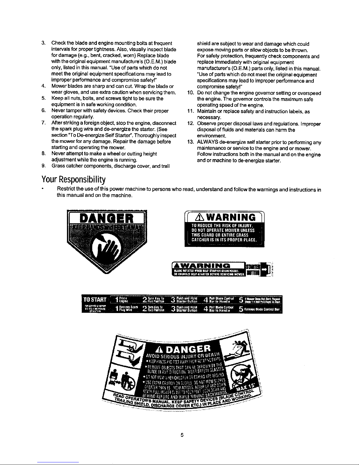
SECTION12: PARTSLISTFORMODELSERIES
74
71
\
7
\
8
12
23
2O
14
73
21
22
53
52
28
"30
31
35
4O
41
39
43_
49
2O
Page 21

ModelSeries
ReL No Pa_ No.
1 731-1057
2 731-0620
3 731-1058
4 731-1059
5 710-1667A
6 746-0960
7 647-0058
8 749-1405
9 731-2532
10 731-2533
11 720-0428
12 732-1171
13 782-0156
14 746-1141
15 710-1256
16 715-0168
17 716-0209
18 720-0279
19 710-1205
20 710-1174
21 720-0314
22 749-0928
23 710-0501
24 736-0451
25 710-0324
26 726-0240
27 732-1172
28 711-1293
29 631o0075B
30 712-0271
31 710-1008
32 782-5004
33 782-5003
34 710-1017
35 782-0080A
36 782-5002
37 712-0798
38 736-0331
39 710-0216
40 7510042824
Description
Upper Drive Cover
Drive Lever
Lower Ddve Cover
Mounting Cap
Screw #10-12:75
Ddve Cable
Control Bail Lever
Upper Handle
Control Cover LH
Control Cover RH
Button
Compression Spring
Lever
Control Cable 58.25" Lg.
Hi-Low Screw
Pin
Retention Ring
Knob
Eye Bolt 1/4-20
Carriage Bolt 5/16-18 x 2.0
Knob
Lower Handle
Hex Hd. Cap Screw
Saddle Washer
Hex Lock Nut 1/4-20
Cable Tie
Torsion Spring
Pin-Belt Keeper
Engine Spacer
Hex Nut 1/4-20 Thread
lapp Screw w/Hex Lock Wash
Rear Baffle Right
Rear Baffle Left
Scr. AB: 1/4-14.625 Trust
Deck 21" RD
FrontBaffle
BellWasher .39 x 1.13 x .062
Hex Nut 3/.8-16
Hex Screw 3/8-16 x .76
Screw #12 x .457
Ref. No
41
42
43
44
45
46
47
48
49
5O
51
52
53
54
55
56
58
59
60
61
62
63
64
65
66
67
68
69
70
71
72
73
74
75
Pa_ No.
731-1937A
754-0465
712-0324
756-1146A
748-0411
742-0741
736-0452
710-0606
710-1257
712-3005
732-0677
710-0192
720-0275
714-0104
782-7000
682-0515A
682-0516A
682-0511A
682-0512A
710-0896
14766
14765
720-0190
732-0417A
738-0507B
736-0105
734-1979
734-1983
738-0102
731-1426
732-0700
731-1236
732-0678
720-0294
782-5007A
764-0457A
764-6310
764-0311
737-0208
Descdption
FrontDrive Cover - Yellow
V-Belt
Hex Lock Nut 1/4-20
DrivePulley
Blade Adapter
21" MulchingBladew/star
BellWasher .396 I.D. x 1.140 O.D. x
HexScrew 1/4-2 0x 1.50
HexScrew 3/8-24 x 2.50
Hex Nut 3/8-16
Torsion Spdng L.H.
Scr.Tr. Mach #10-24 x .380
Knob
Cotter Pin
Rear Discharge Door
Complete Handle Brkt Ass'y - LH
CompleteHandle BrktAss'y- RH
Handle BrktAss'y- LH
Handle BrktAss'y - RH
Hex Screww/wsh. 1/4-14 x .62
PivotBar- LH
PivotBar - RH
Knob
Spring Lever
ShldrScrew .500 Dia x .434 Long
BellWasher .380 x .880 x.062
Whl. Comp. 8 x 2 PL (Rear)
Wh. Comp. 8 x 2 Fwd. (Front)
Shldr Screw .498 x 1.445
Hubcap: Radial Spoke Yellow
Wire
Rear Flap
Torsion Spdng R.H.
Foam Grip (2 required)
Mulching Plug Baffle
Soft Top Grass Bag
Grass Catcher Frame (Rear)
Grass Catcher Frame (Front)
Bottle of Oil (not shown)
21
Page 22

ModelSeries
40
°\
46
I
_25
4O
IMPORTANT: For a proper working machine, use
Factory Approved Parts.
V-BELTS are specially designed to engage and
disengage safely. A substitute(non OEM) V-Belt can be
dangerous by not d sengagng compete y. ._ /
/-
r"
52
22
Page 23

ModelSeries;.
Re_ No Pa_ No.
1. 712-3025
2. 736-0425
3. 756-1042
4. 736-0425
5. 712-0896
6. 736-0406
7. 782-7598
8. 741-0124
9. 721-0457
10. 750-1050
11. 682-0028
12. 741-0682A
13. 732-0849A
14. 710-0299
15. 736-0570
16. 741-0699
17. 721-0325
18. 618-0300A
19. 721-0329
20. 741-0673
21. 611-0105A
22. 736-0520
23. 717-1492
24. 736-0314
25. 736-0569
26. 618-0299A
27. 741-0672
28. 710-1276
29. 618-0606
30. 732-0708
Description
HexJam Nut 5/16-24
BellWasher .325 x .930 x .045
Pulley.3.82 x .313 x .68
BellWasher .325 x .930 x .645
LockNut 1/4-28
Flat Washer .442 x 1.38 x .060
Belt Keeper
BallBearing
OilSeal
Flange Spacer
Idler BracketAssembly
BearingSleeve
Flat Washer .504 x.700 x.03O
Hex Cap Screw 1/4-28 x 1.00
Flat Washer .865 x1.145 x .030
Needle Bearing .438 x.625 x .500
Plug 1/4 x .437
Upper Housing
Oil Seal .500 x .687 x .094
FlangeBearing
Output Shaft
FlatWasher .504 x .700 x .030
PinionShaft 10T
ThrustWasher .375 x .70 x .030
ThrustWasher .388 x .625 x .062
LowerHousing
FlangeBearing .378 x .531 x .370
Hex Screw w/Washer 1/4-20 x .750
TransmissionAssembly Comp.
(IncludesRef.# 1to Ref. #30)
BearingRetainer
Ref.No
31.
32.
33.
34.
35.
36.
37.
38.
39.
40.
41.
42.
43.
44.
45.
46.
47.
48.
49.
50.
51.
52.
53.
54.
55.
56.
57.
58.
59.
60.
Pa_ No.
741-0604
748-0355
736-0447
782-0512B
782-0511A
682-0509
732-0706
732-0707
720-0190
710-0216
736-0474
716-0102
782-7551
717-1762
717-1761
634-0021A
731-1426
682-0512A
682-0511A
682-0030
715-0221
736-3013
714-0101
738-1002
754-0465
716-0865
750-1165
750-1166
736-0331
712-0798
Description
BearingSleeve .50 I.D.
BearingSupport
Wave Washer 1.5 x 1.0 x .029
RH HeightAdj. Plate
LH HeightAdj. Plate
PivotPlate Assembly
RH FrontLever
LH Front Lever
Knob
Hex Cap Screw3/8-16 x .75
Washer DD 1.5"O.D.
Snap Ring 1.0 dia.
Wheel Dust Cap
Gear 14T R.H.
Gear 14T L.H.
Wheel, 8x2 x 1.75
Hubcap:Yellow
RH HeightAdj. Complete
LH HeightAdj. Complete
Cable IdlerBracket
DowelPin
FlatWasher 1/2 x 1.00 x .063
CotterPin .08 x 1.42
Screw
Belt
Snap Ring
Slev.Spacer
Slev. Spacer
BellWasher
Hex Nut 3/8-16
23
Page 24

MANUFACTURER'S LIMITED WARRANTY FOR:
YaRDMaN:)//
The limited warranty set forth below is given by MTD
PRODUCTS INC ("MTD") with respect to new merchandise
purchasedand used in the United States, its possessions
and territohes.
MTD warrants this product against defects in material and
workmanshipfor a period of two(2) years commencingon
the dateof ohginal pumhase and will, at its option,repairor
replace, free of charge, any part found to be defective in
material or workmanship. This limitedwarranty shall only
apply if this producthas been operated and maintained in
accordance with the Operator's Manual furnished with the
product,and has not been subjectto misuse, abuse, com-
memial use, neglect, accident, improper maintenance,
alteration, vandalism, theft, fire, water or damage because
of otherperilor natural disaster.Damage resultingfrom the
installation or use of any accessory or attachment not
approved by MTD Products Inc.for usewiththe product(s)
covered by this manual will void your warranty as to any
resultingdamages.
Normal wear parts or components thereof are subject to
separate terms as follows: All normalwear part or compo-
nent failures will be covered on the product for a pedod of
90 days regardless of cause. After 90 days, but within the
two year period, normal wear part failures will be covered
ONLY IF caused by defects in material or workmanship of
OTHER component parts. Normal wear parts and compo-
nents include, but are not limited to, belts, blades, blade
adapters, grass bags, dder deck wheels, seats, snow
thrower skid shoes, shave plates and tires. Battenec are
covered by a 90-day limited replacement warranty.
HOW TO OBTAIN SERVICE: Warrantyserviceis available,
WITH PROOF OF PURCHASE THROUGH YOUR LOCAL
AUTHORIZED SERVICE DEALER. To locate the dealer in
your area, please check for a listinginthe Yellow Pages or
contact the Customer Service Departmentof MTD PROD-
UCTS INC by calling 1-800-800-7310 or writingto P.O. Box
368022, Cleveland, Ohio 44136-9722.
This limited warranty does not provide coverage in the
following cases:
a, The engine or component parts thereof. These items
carry a separate manufacturer's warranty. Please refer
to the applicable manufacturer's warranty on these
items.
b.Leg splitter pumps, valves and cylinders have a sepa-
rateone year warranty.
c. Routine maintenance items such as lubricants,filters,
blade sharpening and tune-ups, or adjustments such
as brake adjustments, clutch adjustments or deck
adjustments; and normal deteriorationof the exterior
finish due to use or exposure.
d.MTD does not extend any warranty for productssold
or exported outside of the United States of America,
its possessions and territories, except those sold
through MTD's authorizedchannelsof export distribu-
tion.
No implied warranty, including any implied warranty of
merchantability or fitness for a particular purpose,
applies after the applicable period of express written
warranty above as to the parts as identified. No other
express warranty or guaranty, whether wdtten or oral,
except as mentioned above, given by any person or
entity, including a dealer or retailer, with respect to any
product shall bind MTD. During the period of the War-
ranty, the exclusive remedy is repair or replacement of
the product as set forth above. (Some states do not
allow limitationson how long an impliedwarrantylasts, so
the above limitation may not apply toyou,)
The provisions as set forth in this Warranty provide the
sole and exclusive remedy arising from the sales. MTD
shall not be liable for Incidental or consequential loss
or damages including, without limitation, expenses
incurred for substitute or replacement lawn care ser-
vices, for transportation or for related expenses, or for
rental expenses to temporarily replace a warranted
product. (Some states do notallow the exclusion or limita-
tion of incidentalor consequential damages, sothe above
exclusionor limitationmay notapply toyou.)
In no event shall recovery of any kind be greater than the
amount of the purchaseprice of the product sold. Alteration
of the safety features of the product shall void this War-
ranty. You assume the hsk and liability for loss, damage, or
injury to you and your property and/or to others and their
property arising out of the use or misuse or inability to use
the product.
This limitedwarranty shall not extend to anyoneother than
the odginal purchaser, original lessee or the person for
whom it was purchased as a gift.
How State Law Relates to this Warranty: This limited
warranty gives you specific legalrights, and you may also
have other rightswhichvary from state to state.
 Loading...