

Page 1

Operator's Manual
P R 8 F E S S | 8 N A L
Garden Tractor
Model No. 107.289850 PGT9500 30/54" CRAFTSMAN 2WD
For answers to your questions about this
product, call:
1-800-659-5917
Sears Craftsman Help Line
5 am - 5 pm, Mon- Sat
Nota: Una traducci6n en espa_ol de este Manual del
Operador puede encontrarse en la pagina 33.
Sears Brand Management Corporation, Hoffman Estates, IL 60179 U.S.A.
Visit our Craftsman website: www.craftsman.com
1750727
Revision A
Page 2

Thankyouforpurchasingthisquality-builtCRAFTSMANPROFESSIONALmower.We'repleasedthatyou've
placedyourconfidenceintheCRAFTSMANPROFESSIONALbrand.Whenoperatedandmaintainedaccordingto
theinstructionsinthismanual,yourCRAFTSMANPROFESSIONALproductwillprovidemanyyearsofdependable
service.
This manual contains safety information to make you aware of the hazards and risks associated with mowers and
how to avoid them. This product and its approved attachments/accessories are designed and intended only for lawn
work or snow removal and are not intended for any other purpose. It is important that you read and understand these
instructions thoroughly before attempting to start or operate this equipment. Save these original instructions for
future reference.
Where to Find Us
You never haveto lookfar to find supportand service for your CRAFTSMAN mower. There are authorized service dealers
worldwide who providequality service.You can contact Customer Service by phone at (800) 659-5917, or locatea dealer on the
lntemetat www.sears.com/craftsman.
Mower
Model Number
Serial Number
Engine
Model Type Trim
Date Code
Date Purchased
Copyright © 2010 All rights reserved.
2
Page 3
Identification Numbers 3
Warranty Statement 4
Emissions Statement 5
Operator Safety 6
Safety Instructions 8
Safety Decals 13
Features and Controls 14
Operation 18
Maintenance 22
Storage 28
Troubleshooting 29
Specifications 31
Spanish Operator's Manual 33
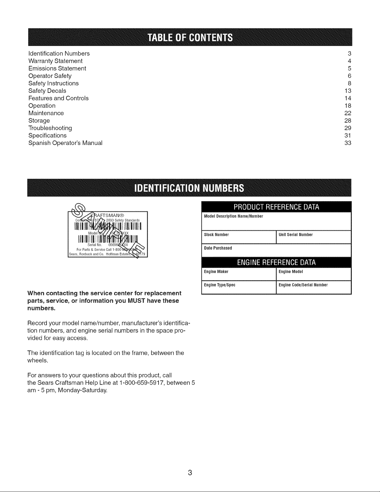
IVledelDescription Name/Number
lIHli[i[Il! xill
Sears, R0ebuck ind Cir.. ofl_l_-an E-starI_79
When contacting the service center for replacement
parts, service, or information you MUST have these
numbers.
Record your model name/number, manufacturer's identifica-
tion numbers, and engine serial numbers in the space pro-
vided for easy access.
The identification tag is located on the frame, between the
wheels.
For answers to your questions about this product, call
the Sears Craftsman Help Line at 1-800-659-5917, between 5
am - 5 pm, Monday-Saturday.
Stock Number Unit Serial Number
Date Purchased
I=1#1__ I-'I:IiI:I_leT-*Ifd
EngineMaker EngineModel
Engine Type/Spec Engine Cede/Serial Number
3
Page 4

CRAFTSMAN PROFESSIONAL FULL WARRANTY
When operated and maintained according to all supplied instructions, if any non-expendable part of this riding equip-
ment fails due to a defect in material or workmanship within two years from the date or purchase, call 1-800-659-5917 to
arrange for free in-home repair.
The frame and front axle will be repaired free of charge for five years from the date of purchase if defective in material or
workmanship.
All of the above warranty coverage applies for only 90 days from the date of purchase if this riding equipment is ever
used for commercial or rental purposes.
in all cases, if repair proves impossible, the riding equipment will be replaced free of charge with the same or an equiva-
lent model.
The battery will be replaced free of charge for 90 days from the date of purchase if defective in material or workmanship
(or testing proves that it will not hold a charge).
This warranty covers ONLY defects in material and workmanship. Sears will NOT pay for:
• Expendable items that become worn during normal use, including but not limited to blades, spark plugs, air clean-
ers, belts, and oil filters.
Standard maintenance servicing, oil changes, or tune-ups.
Tire replacement or repair caused by punctures from outside objects, such as nails, thorns, stumps, or glass.
Tire or wheel replacement or repair resulting from normal wear, accident, or improper operation or maintenance.
Repairs necessary because of operator abuse, including but not limited to damage caused by towing objects be-
yond the capability of the riding equipment, impacting objects that bend the frame or crankshaft, or over-speeding
the engine.
Repairs necessary because of operator negligence, including but not limited to, electrical and mechanical damage
caused by improper storage, failure to use the proper grade and amount of engine oil, failure to keep the deck clear
of flammable debris, or failure to maintain the riding equipment according to the instructions contained in the opera-
tor's manual.
Engine (fuel system) cleaning or repairs caused by fuel determined to be contaminated or oxidized (stale). In gen-
eral, fuel should be used within 30 days of its purchase date.
Normal deterioration and wear of the exterior finishes, or product label replacement.
This warranty applies only while this product is within the United States.
This warranty gives you specific legal rights, and you may also have other rights which vary from state to state.
Sears Brand Management Corporation, Hoffman Estates, IL 60179
4
Page 5
EmissionsControl SystemWarrantyStatement
California,UnitedStatesandCanadaEmissionsControlDefectsWarranty
Statement
The CaliforniaAir ResourceBoard (CARB),U.S.EPAadn B&Sarephased toexplainthe
EmissionsControlSystem Warrantyonyour small off-roadengine (SORE).in Califor-
nia,newsmall off-road enginesmodel year2006 and bter must bedesigned,built and
equippedto meetthe State'sstrigent anti-smog standards.Elsewhereinthe UnitedStates,
newnon-road,spark-ignition enginescertified for modelyear1997 andbter must meet
simibr standardssetforth by the U.S.EPA.B&Smust warrant the emissionscontrol sys-
tem onyour enginefor the periodsof time listed below,providedtherehas beennoabuse,
negbct or impropermaintenanceofyour small off-roadengine.
Youremissions control systemincludesparts suchas the carburetor,air cleaner,ignition
system, fuel line,muffler and catalyticconverter.Alsoincludedmay beconnectorsand
otheremissions relatedassemblies.
Wherea warrantablecondition exists,B&Swill repairyour small off-roadengineat no
cost to you including diagnosis, partsand labor.
Briggs& Stratton EmissionsControl DefectsWarranty Coverage
Smalloff-roadenginesarewarrantedrelativetoemissionscontrolpartsdefectsfor a
Owner'sWarrantyResponsibility
As thesmall off-road engineowner,you are responsiblefor the performanceofthe required
maintenancelistedin your OperatingandMaintenanceInstructions. B&S recommends
thatyou retainallyour receiptscovering maintenanceon your small off-road engine,but
B&Scannotdeny warrantysolelyfor thelack of receiptsor for your failureto ensurethe
performanceofall scheduledmaintenance.
As thesmall off-road engineowner,you should howeverbe awarethatB&S maydenyyou
warrantycoverageif your small off-roadengineor a parthasfaileddue to abuse,neglect,
impropermaintenanceor unapprovedmodifications.
You areresponsiblefor presentingyour small off-road engineto an AuthorizedB&S Service
Dealerassoon asa problemexists.The undisputedwarrantyrepairsshould becompleted
in a reasonableamount of time, notto exceed30 days.
if you haveanyquestionsregardingyour warranty rights and responsibilities,you should
contacta B&SServiceRepresentativeat (414) 259-5262.
Theemissions warrantyis a defectswarranty. Defectsarejudged on normal engineperfor-
mance.Thewarrantyis not relatedtoan in-useemissionstest.
periodoftwoyears,subjecttoprovisionssetforthbelow.If anycoveredparton your
engineisdefective,thepartwillberepairedor replacedbyB&S.
The following are specific provisions relative to your Emissions Control Defects Warranty Coverage.It is inaddition to the B&S engine warranty for non-regulated engines found
in the Operating and Maintenance Instructions.
1. Warranted Parts 3.
Coverageunder this warranty extendsonly to the parts listed below (the emissions
control systems parts) to the extent these parts were present on the engine
purchased.
a. FuelMetering System
, Coldstart enrichment system (soft choke)
Carburetor and internal parts
, Fuelpump 4.
Fuelline, fuel line fittings, clamps
Fueltank, cap and tether
Carboncanister
b. Air Induction System
Aircleaner
Intake manifold
Purgeand vent line
c. Ignition System 5.
. Sparkplug(s)
Magneto ignition system
d. Catalyst System
Catalyticconverter
Exhaust manifold
Air injection system or pulsevalve
e. Miscellaneous Items Usedin Above Systems
Vacuum,temperature, position, time sensitive valves andswitches
Connectors and assemblies
2. Length of Coverage
B&S warrants to the initial owner and eachsubsequent purchaser that the Warranted 6.
Parts shall befree from defects in materials and workmanship which caused the
failure of the Warranted parts for a period of two years from the date the engine is
delivered to a retail purchaser.
No Charge
Repair or replacement of any Warranted Part will be performed at no charge to the
owner, including diagnostic labor which leadsto thedetermination that a War-
ranted Part is defecttive, if the diagnostic work is performed at an Authorized B&S
Service Dealeras listed in the "Yellow Pages" under "Engines, Gasoline,"" Gasoline
Engines," "Lawn Mowers," or similar category.
Claims and CoverageExclusions
Warranty claims shall befiled in accordance with the provisions ofthe B&S Engine
Warranty Policy. Warranty coverageshall be excludedfor failures of Warranted Parts
which are not original B&S parts or because of abuse, neglect or improper main-
tenanceas set forth in the B&S EngineWarranty Policy. B&S is not liable to cover
failures of Warranted Parts caused by the use of add-on, non-original, or modified
parts.
Maintenance
Any Warranted Part which is not scheduled for replacementas required maintenance
or which isscheduled only for regular inspection to the effect of "repair or replace as
necessary" shall be warranted as to defects for the warranty period. Any Warranted
Part which is scheduled for replacement as required maintenance shall be warranted
as to defects only for the period of time up to the first scheduled replacement for
that part. Any replacementpart that is equivalent in performance anddurability may
be used in the performance ofany maintenance or repairs. The owner is responsible
for the performance of all requiredmaintenance, as defined in the B&SOperating
and Maintenance Instructions.
Consequential Coverage
Coveragehereunder shall extend to the failure of any engine components causedby
the failure of anyWarranted Partstill under warranty.
Enginesthat are certified to meet the California Air Resources Board (CARB)Emis-
sions Standard must display information regarding the Emissions Durability period
and the Air Index. Briggs & Stratton makes this information available to the con-
sumer on our emissions labels. The engine emissions labelwill indicate certification
information.
The Emissions gnrability Period describes the number of hours of actual running
time for which the engine is certified to beemissions compliant, assuming proper
maintenance in accordance wiht the Operating and Maintenance Instructions. The
following categories are used:
Moderate:
Engineis certified to be emissions compliant for 125hours of actual running time.
intermediate:
Engineiscertifiedto beemissionscompliantfor 250hoursofactualrunningtime.
Extended:
Engineis certified to be emissions compliant for 500 hours of actual engine running time.
For example, a typical walk-behind lawn mower is used20 to 25 hours per year. There-
fore, the Emissions Durability Period of an enginewith an intermediate rating would
equate to 10 to 12years.
Briggs & Stratton engines are certified to meet the United States Environmental Protec-
tion Agency (ESEPA)Phase2 emissions standards. For Phase 2 certified engines, the
Emissions Compliance Period referred to on the Emissions Compliance label indicates the
number of operating hoursfor which the engine has been shown to meet Federalemis-
sions requirements.
For engines less than 225 cc displacement.
Category C= 125 hours, Category B=250 hours, Category A= 500 hours
For engines of 225 cc or more displacement.
Category C=250 hours, Category B= 500 hours, Category A= 1000 hours
5
Page 6
Operating Safety
Congratulations on purchasing a superior-quality piece of lawn and gar-
den equipment. Our products are designed and manufactured to meet
or exceed all industry standards for safety.
Power equipment is only as safe as the operator. If it is misused, or not
properly maintained, it can be dangerous! Remember, you are respon-
sible for your safety and that of those around you.
Use common sense, and think through what you are doing. If you are
not sure that the task you are about to perform can be safely done with
the equipment you have chosen, ask a professional: contact your local
authorized dealer.
Read the Manual
The operator's manual contains important safety information you need
to be aware of BEFORE you operate your unit as well as DURING op-
eration.
Safe operating techniques, an explanation of the product's features and
controls, and maintenance information is included to help you get the
most out of your equipment investment.
Be sure to completely read the Safety Rules and Information found on
the following pages. Also completely read the Operation section.
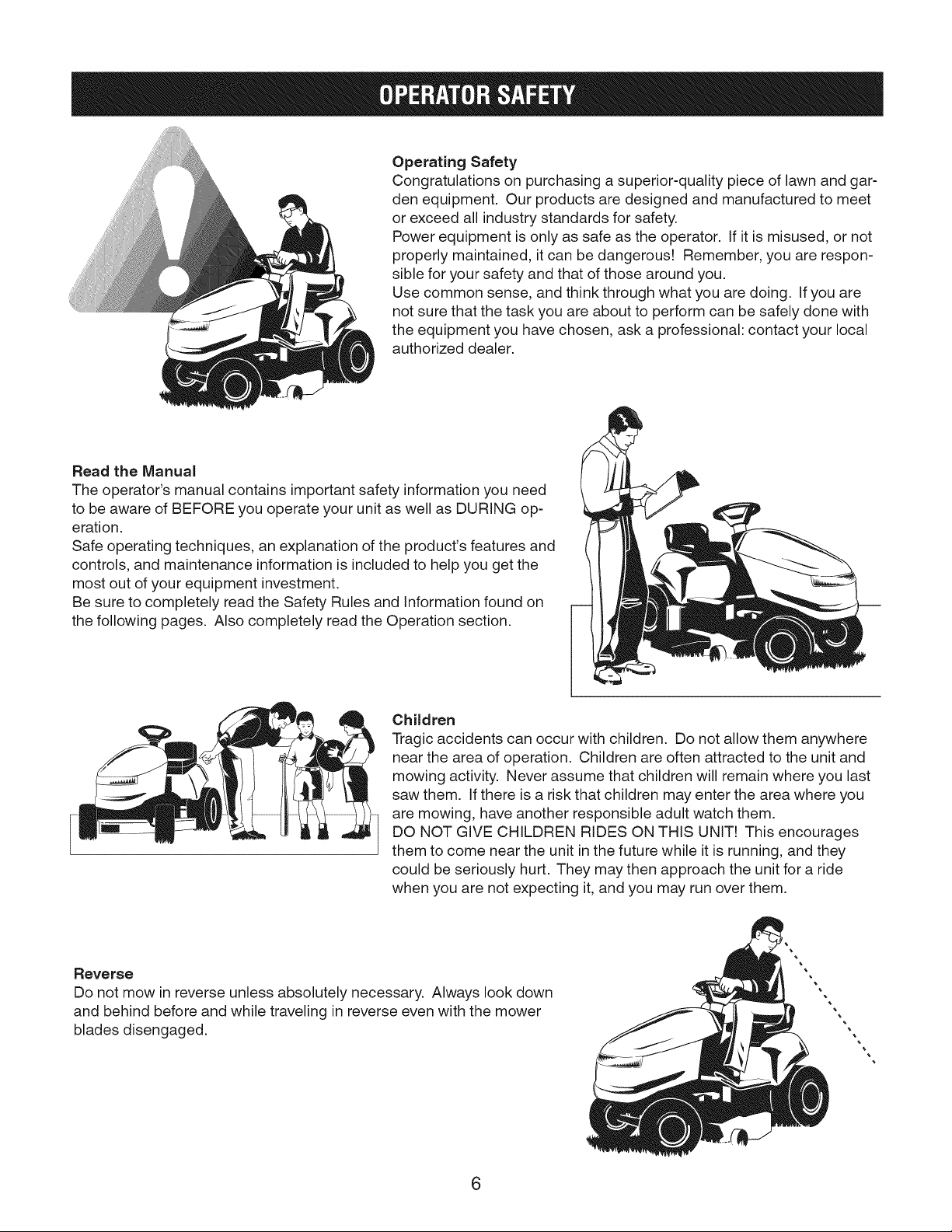
Children
Tragic accidents can occur with children. Do not allow them anywhere
near the area of operation. Children are often attracted to the unit and
mowing activity. Never assume that children will remain where you last
saw them. If there is a risk that children may enter the area where you
are mowing, have another responsible adult watch them.
DO NOT GIVE CHILDREN RIDES ON THIS UNIT! This encourages
them to come near the unit in the future while it is running, and they
could be seriously hurt. They may then approach the unit for a ride
when you are not expecting it, and you may run over them.
Reverse
Do not mow in reverse unless absolutely necessary. Always look down
and behind before and while traveling in reverse even with the mower
blades disengaged.
6
Page 7
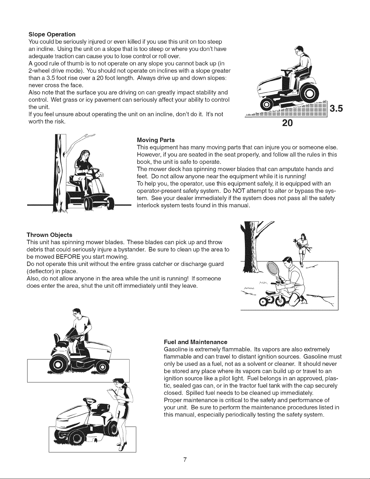
Slope Operation
You could be seriously injured or even killed if you use this unit on too steep
an incline. Using the unit on aslope that is too steep or where you don't have
adequate traction can cause you to lose control or roll over.
A good rule of thumb is to not operate on any slope you cannot back up (in
2-wheel drive mode). You should not operate on inclines with a slope greater
than a 3.5 foot rise over a 20 foot length. Always drive up and down slopes:
never cross the face.
Also note that the surface you are driving on can greatly impact stability and
control. Wet grass or icy pavement can seriously affect your ability to control
the unit.
If you feel unsure about operating the unit on an incline, don't do it. It's not
worth the risk.
Moving Parts
This equipment has many moving parts that can injure you or someone else.
However, if you are seated in the seat properly, and follow all the rules in this
book, the unit is safe to operate.
The mower deck has spinning mower blades that can amputate hands and
feet. Do not allow anyone near the equipment while it is running!
To help you, the operator, use this equipment safely, it is equipped with an
operator-present safety system. Do NOT attempt to alter or bypass the sys-
tem. See your dealer immediately ifthe system does not pass all the safety
interlock system tests found in this manual.
Thrown Objects
This unit has spinning mower blades. These blades can pick up and throw
debris that could seriously injure a bystander. Be sure to clean up the area to
be mowed BEFORE you start mowing.
Do not operate this unit without the entire grass catcher or discharge guard
(deflector) in place.
Also, do not allow anyone in the area while the unit is running! if someone
does enter the area, shut the unit off immediately until they leave.
Fuel and Maintenance
Gasoline is extremely flammable. Its vapors are also extremely
flammable and can travel to distant ignition sources. Gasoline must
only be used as a fuel, not as a solvent or cleaner. It should never
be stored any place where its vapors can build up or travel to an
ignition source like a pilot light. Fuel belongs in an approved, plas-
tic, sealed gas can, or in the tractor fuel tank with the cap securely
closed. Spilled fuel needs to be cleaned up immediately.
Proper maintenance is critical to the safety and performance of
your unit. Be sure to perform the maintenance procedures listed in
this manual, especially periodically testing the safety system.
Page 8
important Safety instructions
SAVE THESE iNSTRUCTiONS - This manual contains
important instructions that should be followed during the
initial set-up, the operation, and the maintenance of the
equipment.
WARNING The engine exhaust from this
product contains chemicals known to the State of
California to cause cancer, birth defects, or other
reproductive harm.
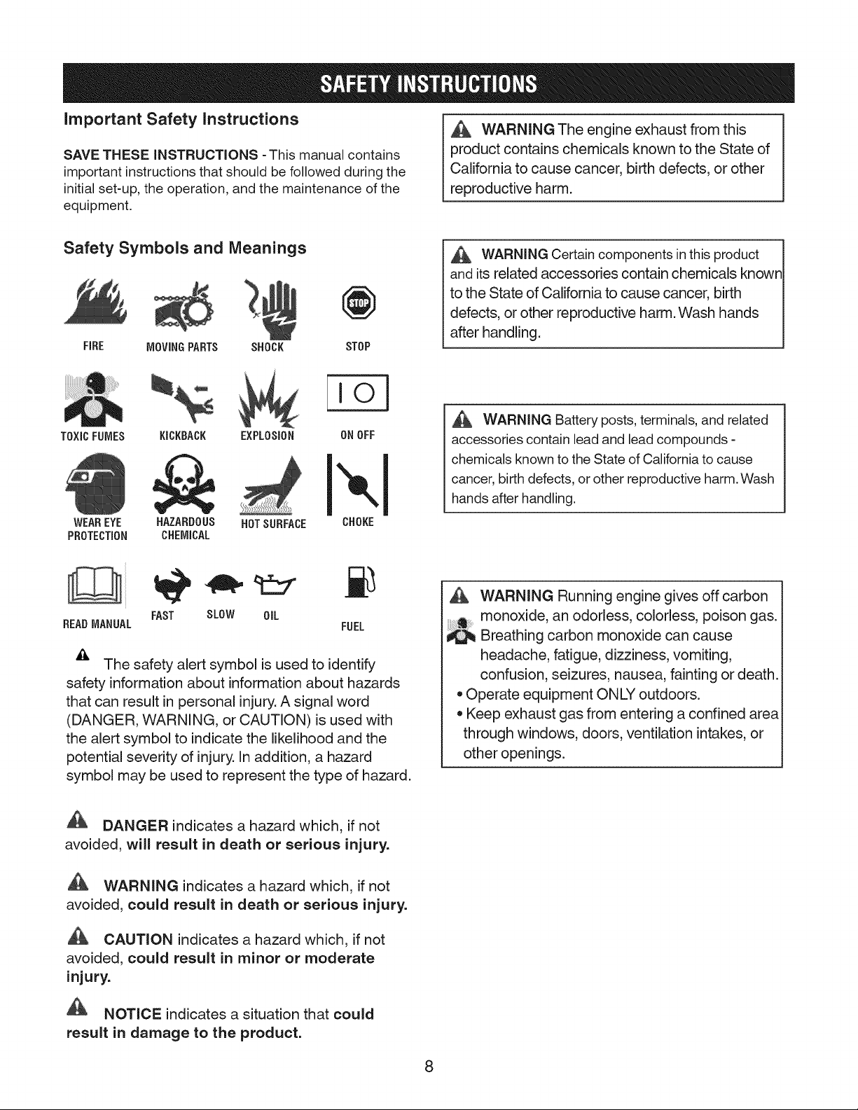
Safety Symbols and Meanings
@
FiRE MOVINGPARTS SHOCK
TOXICFUMES KICKBACK EXPLOSION
WEAREYE HAZARDOUS HOTSURFACE
PROTECTION CHEMICAL
BEADMANUAL
The safety alert symbol is used to identify
safety information about information about hazards
that can result in personal injury.A signal word
(DANGER, WARNING, or CAUTION) is used with
the alert symbol to indicate the likelihood and the
potential severity of injury. In addition, a hazard
symbol may be used to represent the type of hazard.
FAST SLOW OIL
STOP
io]
ONOFF
CHOKE
FUEL
WARNING Certain components in this product
and its related accessories contain chemicals knowr
to the State of California to cause cancer, birth
defects, or other reproductive harm. Wash hands
after handling.
WARNING Battery posts, terminals, and related
accessories contain lead and lead compounds -
chemicals known to the State of California to cause
cancer, birth defects, or other reproductive harm. Wash
hands after handling.
WARNING Running engine gives off carbon
monoxide, an odorless, colorless, poison gas.
Breathing carbon monoxide can cause
headache, fatigue, dizziness, vomiting,
confusion, seizures, nausea, fainting or death.
* Operate equipment ONLY outdoors.
* Keep exhaust gas from entering a confined area
through windows, doors, ventilation intakes, or
other openings.
DANGER indicates a hazard which, if not
avoided, will result in death or serious injury.
WARNING indicates a hazard which, if not
avoided, could result in death or serious injury.
CAUTION indicates a hazard which, if not
avoided, could result in minor or moderate
injury.
NOTICE indicates a situation that could
result in damage to the product.
8
Page 9
Readthese safety rules and followthem closely.Failuretoobeythese rulescould resultin lossof control of unit,severe
personalinjury or deathto you, or bystanders,ordamage to propertyor equipment.This mowingdeck is capable of
amputating hands and feet and throwing objects. The triangle _ intext signifiesimportantcautionsor warnings
which must befollowed.
GENERAL OPERATION
1. Read, understand, and follow all instructions in the
manual and on the unit before starting.
2. Do not put hands or feet near rotating parts or under
the machine. Keep clear of the discharge opening at
all times.
3. Only allow responsible adults, who are familiar with
the instructions, to operate the unit (local regulations
can restrict operator age).
4. Clear the area of objects such as rocks, toys, wire,
etc., which could be picked up and thrown by the
blade(s).
5. Be sure the area is clear of other people before
mowing. Stop the unit if anyone enters the area.
6. Never carry passengers.
7. Do not mow in reverse unless absolutely necessary.
Always look down and behind before and while
travelling in reverse.
8. Never direct discharge material toward anyone. Avoid
discharging material against a wall or obstruction.
Material may ricochet back toward the operator. Stop
the blade(s) when crossing gravel surfaces.
9. Do not operate the machine without the entire grass
catcher, discharge guard (deflector), or other safety
devices in place.
10. Slow down before turning.
11. Never leave a running unit unattended. Always
disengage the PTO, set parking brake, stop engine,
and remove starter insert before dismounting.
12. Disengage blades (PTO) when not mowing. Shut off
engine and wait for all parts to come to a complete
stop before cleaning the machine, removing the grass
catcher, or unclogging the discharge guard.
13. Operate the machine only in daylight or good artificial
light.
14. Do not operate the unit while under the influence of
alcohol or drugs.
15 Watch for traffic when operating near or crossing
roadways.
16. Use extra care when loading or unloading the unit into
a trailer or truck.
17. Always wear eye protection when operating this unit.
18. Data indicates that operators, age 60 years and
above, are involved in a large percentage of power
equipment-related injuries. These operators should
evaluate their ability to operate the equipment safely
enough to protect themselves and others from injury.
19. Follow the manufacturer's recommendations for wheel
weights or counterweights.
20. Keep in mind the operator is responsible for accidents
occurring to other people or property.
21. All drivers should seek and obtain professional and
practical instruction.
22. Always wear substantial footwear and trousers. Never
operate when barefoot or wearing sandals.
23. Before using, always visually check that the blades
and blade hardware are present, intact, and secure.
Replace worn or damaged parts.
24. Disengage attachments before: refueling, removing
an attachment, making adjustments (unless the
adjustment can be made from the operator's position).
25. When the machine is parked, stored, or left
unattended, lower the cutting means unless a positive
mechanical lock is used.
26. Before leaving the operator's position for any reason,
engage the parking brake (if equipped), disengage the
PTO, stop the engine, and remove the starter insert.
27. To reduce fire hazard, keep the unit free of grass,
leaves, & excess oil. Do not stop or park over dry
leaves, grass, or combustible materials.
TRANSPORTING AND STORAGE
1. When transporting the unit on an open trailer, make
sure it is facing forward, in the direction of travel, ifthe
unit is facing backwards, wind lift could damage the
unit.
2. Always observe safe refueling and fuel handling
practices when refueling the unit after transportation or
storage.
3. Never store the unit (with fuel) in an enclosed poorly
ventilated structure. Fuel vapors can travel to an
ignition source (such as afurnace, water heater, etc.)
and cause an explosion. Fuel vapor is also toxic to
humans and animals.
4. Always follow the engine manual instructions for
storage preparations before storing the unit for both
short and long term periods.
5. Always follow the engine manual instructions for
proper start-up procedures when returning the unit to
service.
6. Never store the unit or fuel container inside where
there is an open flame or pilot light, such as in a water
heater. Allow unit to cool before storing.
9
Page 10
SLOPE OPERATION
Slopes are a major factor related to loss-of-control and tip-
over accidents, which can result in severe injury or death.
Operation on all slopes requires extra caution. If you cannot
back up the slope or ifyou feel uneasy on it, do not operate
on it.
Control of a walk-behind or ride-on machine sliding on a
slope will not be regained by the application of the brake.
The main reasons for loss of control are: insufficient tire grip
on the ground, speed too fast, inadequate braking, the type
of machine is unsuitable for its task, lack of awareness of the
ground conditions, incorrect hitching and load distribution.
1. Mow up and down slopes, not across.
2. Watch for holes, ruts, or bumps. Uneven terrain could
overturn the unit. Tall grass can hide obstacles.
3. Choose a slow speed so that you will not have to stop
or change speeds while on the slope.
4. Do not mow on wet grass. Tires may loose traction.
5. Always keep unit ingear especially when traveling
down slopes. Do not shift to neutral and coast
downhill.
6. Avoid starting, stopping, or turning on a slope, if tires
lose traction, disengage the blade(s) and proceed
slowly straight down the slope.
7. Keep all movement on slopes slow and gradual. Do
not make sudden changes in speed or direction, which
could cause the machine to rollover.
8. Use extra care while operating machines with grass
catchers or other attachments; they can affect the
stability of the unit. Do not use on steep slopes.
9. Do not try to stabilize the machine by putting your foot
on the ground (ride-on units).
10. Do not mow near drop-offs, ditches, or embankments.
The mower could suddenly turn over if a wheel is over
the edge of a cliff or ditch, or if an edge caves in.
11. Do not use grass catchers on steep slopes.
12. Do not mow slopes if you cannot back up them.
13. See your authorized dealer/retailer for
recommendations of wheel weights or counterweights
to improve stability.
14. Remove obstacles such as rocks, tree limbs, etc.
15. Use slow speed. Tires may lose traction on slopes
even through the brakes are functioning properly.
16. Do not turn on slopes unless necessary, and then, turn
slowly and gradually downhill, if possible.
TOWED EQUIPMENT (RIDE-ON UNITS)
1. Tow only with a machine that has a hitch designed for
towing. Do not attach towed equipment except at the
hitch point.
2. Follow the manufacturer's recommendations for
weight limit for towed equipment and towing on slopes.
3. Never allow children or others in or on towed
equipment.
4. On slopes, the weight of the towed equipment may
cause loss of traction and loss of control.
5. Travel slowly and allow extra distance to stop.
6. Do not shift to neutral and coast down hill.
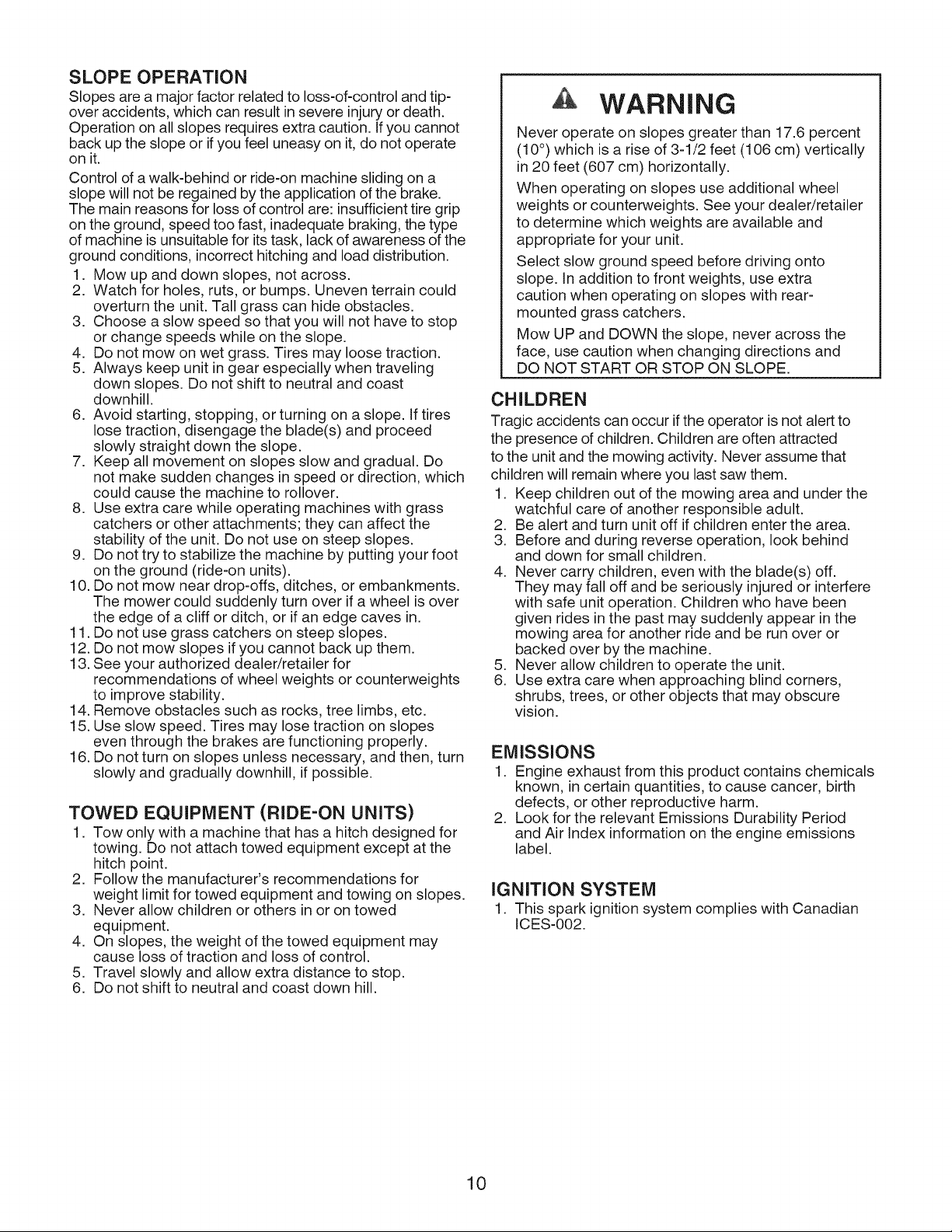
WARNING
Never operate on slopes greater than 17.6 percent
(10°) which is a rise of 3-1/2 feet (106 cm) vertically
in 20 feet (607 cm) horizontally.
When operating on slopes use additional wheel
weights or counterweights. See your dealer/retailer
to determine which weights are available and
appropriate for your unit.
Select slow ground speed before driving onto
slope. In addition to front weights, use extra
caution when operating on slopes with rear-
mounted grass catchers.
Mow UP and DOWN the slope, never across the
face, use caution when changing directions and
DO NOT START OR STOP ON SLOPE.
CHILDREN
Tragic accidents can occur if the operator is not alert to
the presence of children. Children are often attracted
to the unit and the mowing activity. Never assume that
children will remain where you last saw them.
1. Keep children out of the mowing area and under the
watchful care of another responsible adult.
2. Be alert and turn unit off if children enter the area.
3. Before and during reverse operation, look behind
and down for small children.
4. Never carry children, even with the blade(s) off.
They may fall off and be seriously injured or interfere
with safe unit operation. Children who have been
given rides in the past may suddenly appear in the
mowing area for another ride and be run over or
backed over by the machine.
5. Never allow children to operate the unit.
6. Use extra care when approaching blind corners,
shrubs, trees, or other objects that may obscure
vision.
EMISSIONS
1. Engine exhaust from this product contains chemicals
known, in certain quantities, to cause cancer, birth
defects, or other reproductive harm.
2. Look for the relevant Emissions Durability Period
and Air Index information on the engine emissions
label.
iGNITION SYSTEM
1. This spark ignition system complies with Canadian
ICES-002.
10
Page 11

SERVICE AND MAINTENANCE
Safe Handling of Gasoline
1. Extinguish all cigarettes, cigars, pipes, and other
sources of ignition.
2. Use only approved gasoline containers.
3. Never remove the gas cap or add fuel with the engine
running. Allow the engine to cool before refueling.
4. Never fuel the machine indoors.
5. Never store the machine or fuel container where there
is an open flame, spark, or pilot light such as near a
water heater or other appliance.
6. Never fill containers inside a vehicle or on a truck bed
with a plastic bed liner. Always place containers on the
ground away from your vehicle before filling.
7. Remove gas-powered equipment from the truck or
trailer and refuel it on the ground. If this is not possible,
then refuel such equipment on a trailer with a portable
container, rather than from a gasoline dispenser
nozzle.
8. Keep nozzle in contact with the rim of the fuel tank or
container opening at all times until fueling is complete.
Do not use a nozzle lock-open device.
9. If fuel is spilled on clothing, change clothing
immediately.
10. Never over-fill the fuel tank. Replace gas cap and
tighten securely.
11. Use extra care in handling gasoline and other fuels.
They are flammable and vapors are explosive.
12. If fuel is spilled, do not attempt to start the engine but
move the machine away from the area of spillage and
avoid creating any source of ignition until fuel vapors
have dissipated.
13. Replace all fuel tank caps and fuel container caps
securely.
Service & Maintenance
1. Never run the unit in an enclosed area where carbon
monoxide fumes may collect.
2. Keep nuts and bolts, especially blade attachment
bolts, tight and keep equipment in good condition.
3. Never tamper with safety devices. Check their proper
operation regularly and make necessary repairs ifthey
are not functioning properly.
4. Keep unit free of grass, leaves, or other debris build-
up. Clean up oil or fuel spillage, and remove any fuel-
soaked debris. Allow machine to cool before storage.
5. If you strike an object, stop and inspect the machine.
Repair, if necessary, before restarting.
6. Never make adjustments or repairs with the engine
running.
7. Check grass catcher components and the discharge
guard frequently and replace with manufacturer's
recommended parts, when necessary.
8. Mower blades are sharp. Wrap the blade or wear
gloves, and use extra caution when servicing them.
9. Check brake operation frequently. Adjust and service
as required.
10. Maintain or replace safety and instructions labels, as
necessary.
11. Do not remove the fuel filter when the engine is hot
as spilled gasoline may ignite. Do not spread fuel line
clamps further than necessary. Ensure clamps grip
hoses firmly over the filter after installation.
12. Do not use gasoline containing METHANOL, gasohol
containing more than 10% ETHANOL, gasoline
additives, or white gas because engine/fuel system
damage could result.
13. If the fuel tank must be drained, it should be drained
outdoors.
14. Replace faulty silencers/mufflers.
15. Use only factory authorized replacement parts when
making repairs.
16.Always comply with factory specifications on all
settings and adjustments.
17.Only authorized service locations should be utilized for
major service and repair requirements.
18. Never attempt to make major repairs on this unit
unless you have been properly trained. Improper
service procedures can result in hazardous operation,
equipment damage and voiding of manufacturer's
warranty.
19.On multiple blade mowers, take care as rotating one
blade can cause other blades to rotate.
20. Do not change engine governor settings or over-speed
the engine. Operating the engine at excessive speed
can increase the hazard of personal injury.
21. Disengage drive attachments, stop the engine,
remove the starter insert, and disconnect the spark
plug wire(s) before: clearing attachment blockages
and chutes, performing service work, striking an
object, or if the unit vibrates abnormally. After striking
an object, inspect the machine for damage and make
repairs before restarting and operating the equipment.
22. Never place hands near the moving parts, such as a
hydro pump cooling fan, when the tractor is running.
(Hydro pump cooling fans are typically located on top
of the transaxle).
23. Units with hydraulic pumps, hoses, or motors:
WARNING: Hydraulic fluid escaping under pressure
may have sufficient force to penetrate skin and cause
serious injury. If foreign fluid is injected into the skin
it must be surgically removed within afew hours by a
doctor familiar with this form of injury or gangrene may
result. Keep body and hands away from pin holes or
nozzles that eject hydraulic fluid under high pressure.
Use paper or cardboard, and not hands, to search
for leaks. Make sure all hydraulic fluid connections
are tight and all hydraulic hoses and lines are in good
condition before applying pressure to the system. If
leaks occur, have the unit serviced immediately by
your authorized dealer.
24. WARNING: Stored energy device. Improper release of
springs can result in serious personal injury. Springs
should be removed by an authorized technician.
25. Models equipped with an engine radiator: WARNING:
Stored energy device. To prevent serious bodily injury
from hot coolant or steam blow-out, never attempt to
remove the radiator cap while the engine is running.
Stop the engine and wait until it is cool. Even then, use
extreme care when removing the cap.
11
Page 12
Po
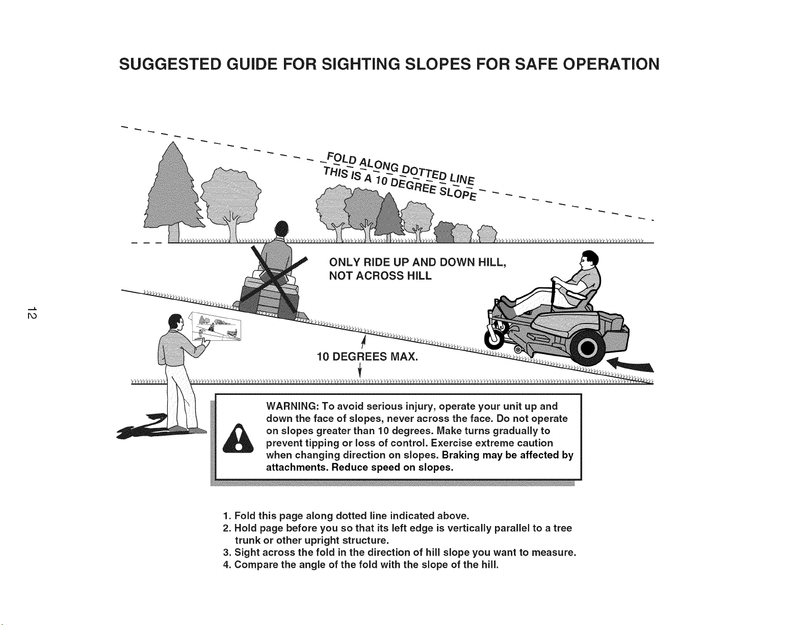
SUGGESTED GUIDE FOR SIGHTING SLOPES FOR SAFE OPERATION
ALONG
SLo
ONLY RiDE UP AND DOWN HILL,
NOT ACROSS HiLL
10 DEGREES MAX.
WARNING: To avoid serious injury, operate your unit up and
down the face of slopes, never across the face. Do not operate
on slopes greater than 10 degrees. Make turns gradually to
prevent tipping or loss of control. Exercise extreme caution
when changing direction on slopes. Braking may be affected by
attachments. Reduce speed on slopes.
1. Fold this page along dotted line indicated above,
2. Hold page before you so that its left edge is vertically parallel to a tree
trunk or other upright structure,
3. Sight across the fold in the direction of hill slope you want to measure,
4, Compare the angle of the fold with the slope of the hill.
Page 13
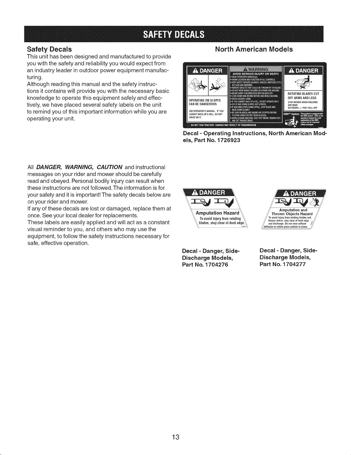
Safety Decals
This unit has been designed and manufactured to provide
you with the safety and reliability you would expect from
an industry leader in outdoor power equipment manufac-
turing.
Although reading this manual and the safety instruc-
tions it contains will provide you with the necessary basic
knowledge to operate this equipment safely and effec-
tively, we have placed several safety labels on the unit
to remind you of this important information while you are
operating your unit.
All DANGER, WARNING, CAUTION and instructional
messages on your rider and mower should be carefully
read and obeyed. Personal bodily injury can result when
these instructions are not followed. The information is for
your safety and it is important! The safety decals below are
on your rider and mower.
If any of these decals are lost or damaged, replace them at
once. See your local dealer for replacements.
These labels are easily applied and will act as a constant
visual reminder to you, and others who may use the
equipment, to follow the safety instructions necessary for
safe, effective operation.
North American lVlodels
Decal - Operating Instructions, North American Mod-
els, Part No. 1726923
"_ Amputation Hazard _,,
"\ Toavoidinjurylromrotating_
',,__lade_,0raycl0arofdock_d_e._
Decal - Danger, Side-
Discharge Models,
Part No. 1704276
/, . //
Decal- Danger, Side-
Discharge Models,
Part No. 1704277
13
Page 14
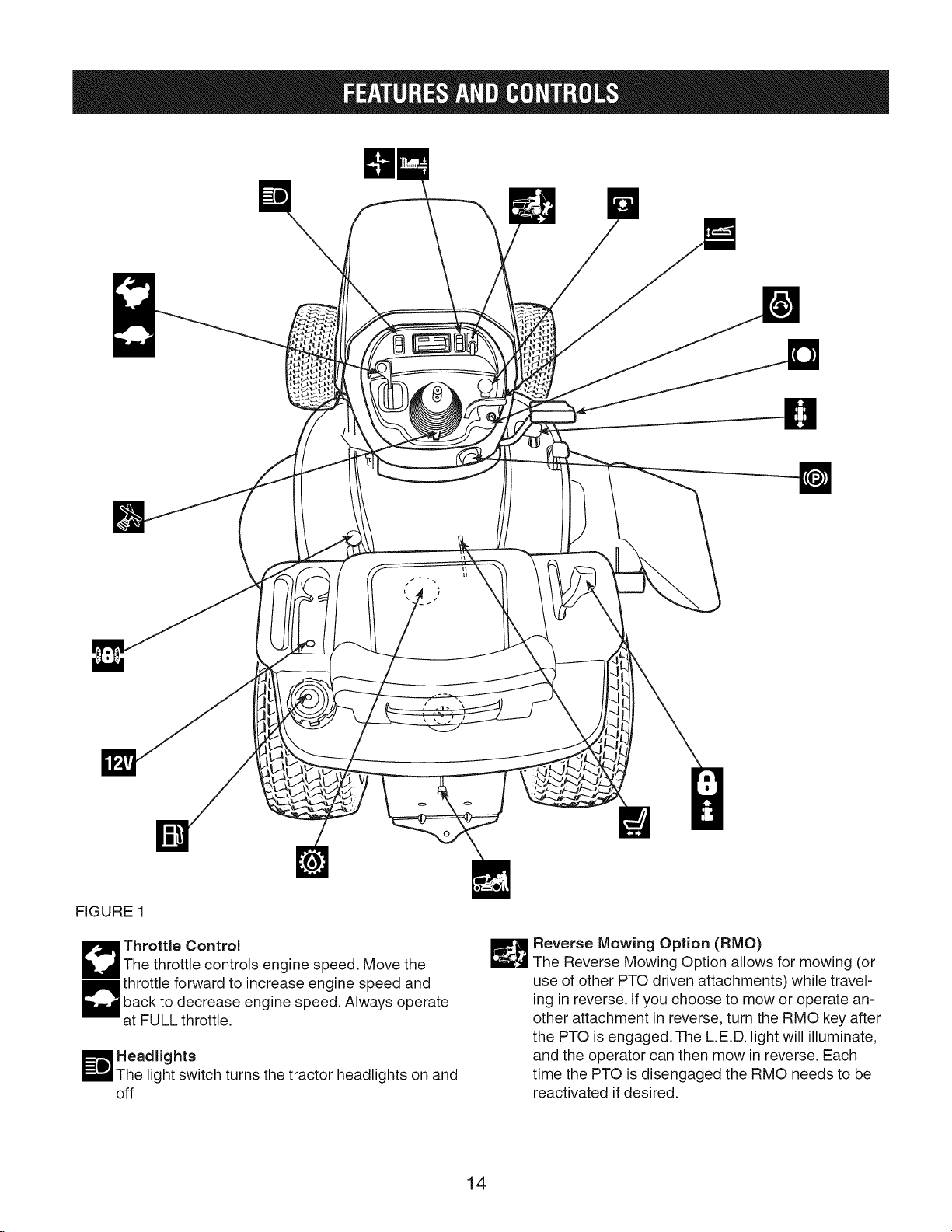
FIGURE 1
1_ Throttle Control
The throttle controls engine speed. Move the
throttle forward to increase engine speed andback to decrease engine speed. Always operate
at FULL throttle.
Headlights
light switch turns the tractor headlights on and
off
_ everse Mowing Option (RMO)
The Reverse Mowing Option allows for mowing (or
use of other PTO driven attachments) while travel-
ing in reverse. If you choose to mow or operate an-
other attachment in reverse, turn the RMO key after
the PTO is engaged.The L.E.D. light will illuminate,
and the operator can then mow in reverse. Each
time the PTO is disengaged the RMO needs to be
reactivated if desired.
14
Page 15

PTO Switch
m
The PTO (Power Take-Off) switch engages and dis-
engages attachments that use the PTO. To engage
the PTO, pull UP on the switch. Push DOWN to
disengage. Note that the operator must be seated
firmly in the tractor seat for the PTO to function.
'1 Ignition Switch
The ignition switch starts and stops the engine, it
has three positions:
OFF Stops the engine and shuts off the electri-
cal system.
RUN Allows the engine to run and powers the
electrical system.
START Cranks the engine for starting.
NOTE: Never leave the ignition switch in the RUN
position with the engine stopped-this drains the
battery.
Cruise Control
FI
The cruise control is used to lock the ground
speed control in forward. Move the lever forward
El
until the desired ground speed is reached. To
disengage the cruise control move the lever
back. In the event you need to stop quickly,
depressing the brake pedal will also return the
cruise control to neutral.
Seat Adjustment Lever
The seat can be adjusted forward and back.
Move the lever, position the seat as desired, and
release the lever to lock the seat into position.
Transmission Release Lever
The transmission release lever deactivates the
transmission so that the tractor can be pushed by
hand. See Pushing the Tractor by Hand.
Transmission Oil Expansion Chamber
Brake Pedal
pressing the brake pedal applies the tractor brake.
Ground Speed Pedals
The tractor's forward ground speed is controlled
by the forward ground speed control pedal. The
tractor's reverse ground speed is controlled by the
reverse ground speed control pedal.
Depressing either pedal will increase ground
speed. Note that the further down the pedal is de-
pressed, the faster the tractor will travel.
Parking Brake
The parking brake knob is used to lock the parking
brake when the tractor is stopped. Fully depressing
the brake pedal and pulling up on the knob engag-
es the parking brake
_ Mower Height of Cut Adjustment
The cutting height adjustment switch controls the
mower cutting height. The cutting height is infinitely
adjustable between 1.0" and 4.0" (2.5 and 10.2 cm).
Transmission oil is added through the transmis-
sion oil expansion chamber. It also serves as
extra holding capacity for oil as the transmission
heats up and the oil expands. See the Engine
Manual for oil level check and fill procedures.
Fuel Tank
I-oremove the cap, turn counterclockwise. On
models with a dashboard display, the fuel gauge is
part of the dashboard. Models without a dashboard
display have a fuel gauge located under the seat.
12-Volt Power Outlet
The power outlet is 12V-DC. Accessory must be
rated at 14 amps or less.
Differential Lock Pedal
Depressing this pedal locks the transmission dif-
ferential, locking both rear wheels into "drive".
Use this feature if the tractor is stuck because one
wheel is slipping. Engage the differential lock at
slow ground speeds only.
15
Steering Tilt Adjust
Use the tilt knob located on the bellows to release
the pivot mechanism and pivot the wheel to the
desired position. Release the tilt knob to lock in
position.
Page 16
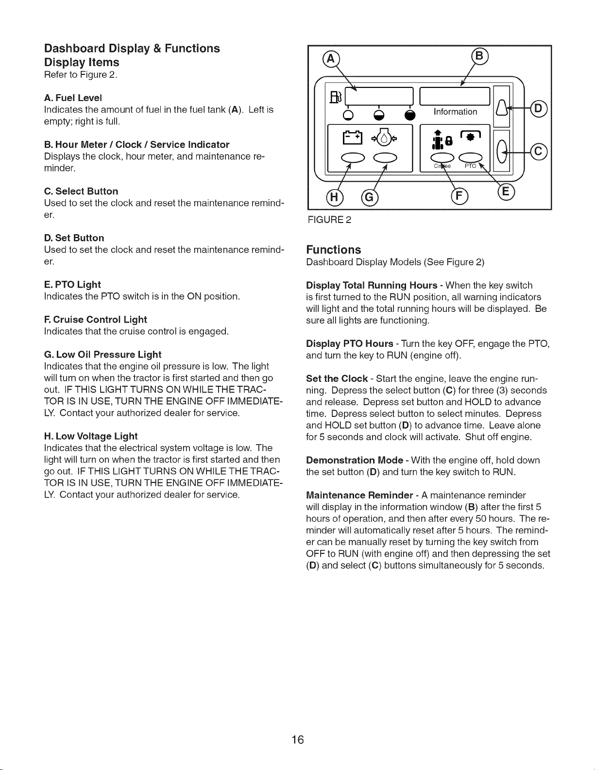
Dashboard Display & Functions
Display Items
Refer to Figure 2.
9
A. Fuel Level
Indicates the amount of fuel in the fuel tank (A). Left is
empty; right is full.
B. Hour Meter / Clock / Service Indicator
Displays the clock, hour meter, and maintenance re-
minder.
C. Select Button
Used to set the clock and reset the maintenance remind-
er.
D. Set Button
Used to set the clock and reset the maintenance remind-
er.
E. PTO Light
Indicates the PTO switch is in the ON position.
F.Cruise Control Light
Indicates that the cruise control is engaged.
G. Low Oil Pressure Light
Indicates that the engine oil pressure is low. The light
will turn on when the tractor is first started and then go
out. IF THIS LIGHT TURNS ON WHILE THE TRAC-
TOR IS IN USE, TURN THE ENGINE OFF IMMEDIATE-
LY. Contact your authorized dealer for service.
H. Low Voltage Light
Indicates that the electrical system voltage is low. The
light will turn on when the tractor is first started and then
go out. IF THIS LIGHT TURNS ON WHILE THE TRAC-
TOR IS IN USE, TURN THE ENGINE OFF IMMEDIATE-
LY. Contact your authorized dealer for service.
I[
o €
e
formation J
;i;e I
I
FIGURE 2
Functions
Dashboard Display Models (See Figure 2)
Display Total Running Hours - When the key switch
is first turned to the RUN position, all warning indicators
will light and the total running hours will be displayed. Be
sure all lights are functioning.
Display PTO Hours - Turn the key OFF, engage the PTO,
and turn the key to RUN (engine off).
Set the Clock - Start the engine, leave the engine run-
ning. Depress the select button (C) for three (3) seconds
and release. Depress set button and HOLD to advance
time. Depress select button to select minutes. Depress
and HOLD set button (D) to advance time. Leave alone
for 5 seconds and clock will activate. Shut off engine.
Demonstration Mode - With the engine off, hold down
the set button (D) and turn the key switch to RUN.
Maintenance Reminder - A maintenance reminder
will display in the information window (B) after the first 5
hours of operation, and then after every 50 hours. The re-
minder will automatically reset after 5 hours. The remind-
er can be manually reset by turning the key switch from
OFF to RUN (with engine off) and then depressing the set
(D) and select (C) buttons simultaneously for 5 seconds.
®
©
16
Page 17
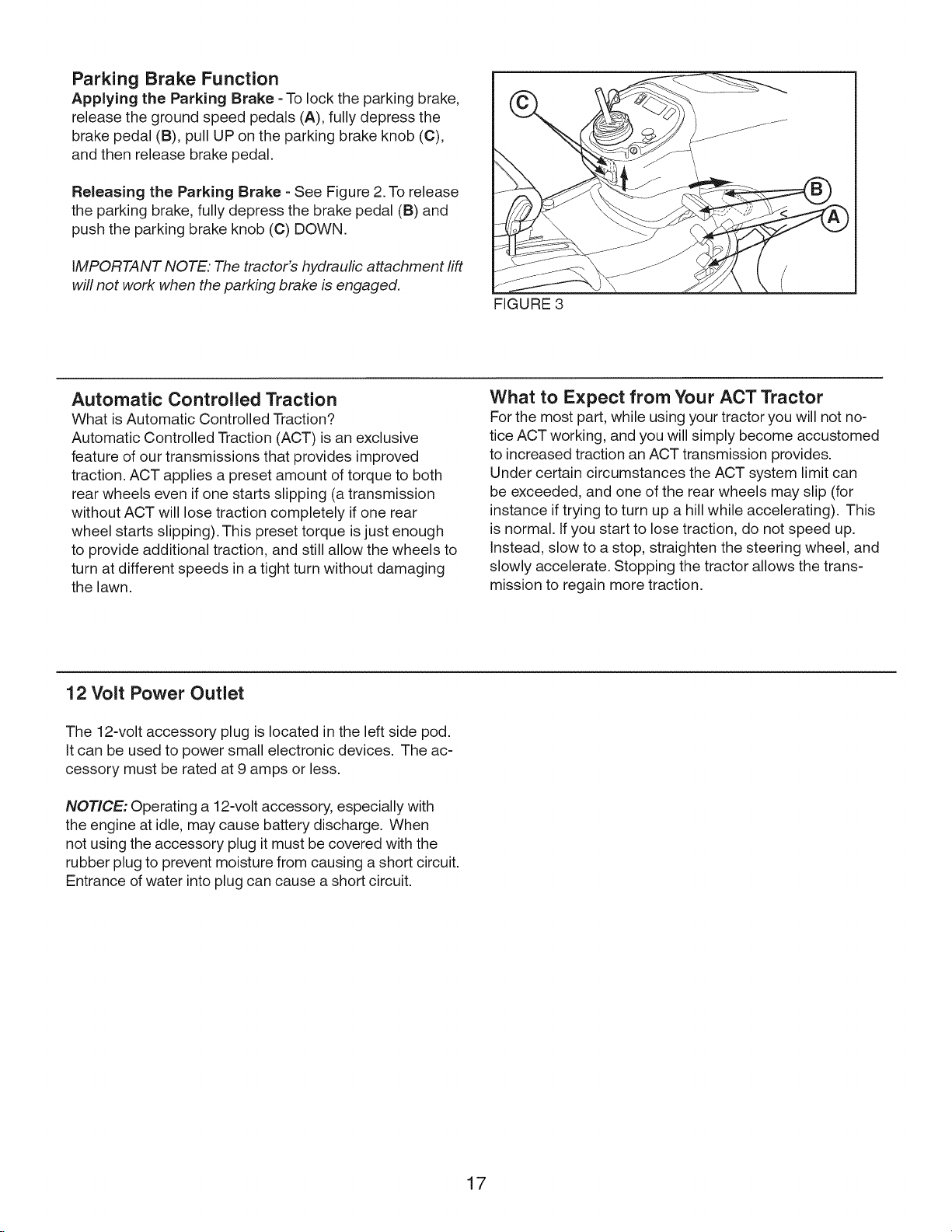
Parking Brake Function
Applying the Parking Brake - To lock the parking brake,
release the ground speed pedals (A), fully depress the
brake pedal (B), pull UP on the parking brake knob (C),
and then release brake pedal.
Releasing the Parking Brake - See Figure 2. To release
the parking brake, fully depress the brake pedal (B) and
push the parking brake knob (C) DOWN.
IMPORTANT NOTE. The tractor's hydraulic attachment lift
will not work when the parking brake is engaged.
FIGURE 3
Automatic Controlled Traction
What is Automatic Controlled Traction?
Automatic Controlled Traction (ACT) is an exclusive
feature of our transmissions that provides improved
traction. ACT applies a preset amount of torque to both
rear wheels even if one starts slipping (a transmission
without ACT will lose traction completely if one rear
wheel starts slipping). This preset torque is just enough
to provide additional traction, and still allow the wheels to
turn at different speeds in a tight turn without damaging
the lawn.
12 Volt Power Outlet
The 12-volt accessory plug is located in the left side pod.
It can be used to power small electronic devices. The ac-
cessory must be rated at 9 amps or less.
NOTICE: Operating a 12-volt accessory, especially with
the engine at idle, may cause battery discharge. When
not using the accessory plug it must be covered with the
rubber plug to prevent moisture from causing a short circuit.
Entrance of water into plug can cause a short circuit.
What to Expect from Your ACT Tractor
For the most part, while using your tractor you will not no-
tice ACT working, and you will simply become accustomed
to increased traction an ACT transmission provides.
Under certain circumstances the ACT system limit can
be exceeded, and one of the rear wheels may slip (for
instance if trying to turn up a hill while accelerating). This
is normal. If you start to lose traction, do not speed up.
Instead, slow to a stop, straighten the steering wheel, and
slowly accelerate. Stopping the tractor allows the trans-
mission to regain more traction.
17
Page 18
General Operating Safety
Be sure to read all information in the Operator Safety
section before attempting to operate this unit. Become
familiar with all of the controls and how to stop the unit.
WARNING
If the unit does not pass a safety test, do not oper-
ate it. See an authorized dealer.
Safety Interlock System Tests
This unit is equipped with a Safety Interlock System.
Do not attempt to bypass or tamper with the switches/
devices.
Test 1 -- Engine should NOT crank if:
• PTO switch is ON, OR
• Brake pedal is NOT fully depressed (parking brake
OFF), OR
• The cruise control lever is NOT in NEUTRAL.
Test 2 -- Engine SHOULD crank and start if:
• Operator is sitting in seat, AND.
• PTO switch is OFF, AND
• Brake pedal is fully depressed (parking brake ON),
AND
• The cruise control is in NEUTRAL.
Test 3 -- Engine should SHUT OFF if:
• Operator rises off seat with PTO engaged, OR
• Operator rises off seat with brake pedal NOT fully
depressed (parking brake OFF).
Test 4 -- Check Mower Blade Stopping Time
Mower blades and mower drive belt should come to a
complete stop within five seconds after electric PTO
switch is turned OFF. If mower drive belt does not stop
within five seconds, see an authorized dealer.
Test 5 -- Reverse Mow Option (RMO) Check
• Engine should shut off if reverse travel is attempted
if the PTO has been switched on and RMO has not
been activated.
• RMO light should illuminate when RMO has been
activated.
WARNING
Mowing in reverse can be hazardous to bystand-
ers. Tragic accidents can occur if the operator is not alert
to the presence of children. Never activate the RMO if
children are present. Children are often attracted to the
unit and the mowing activity.
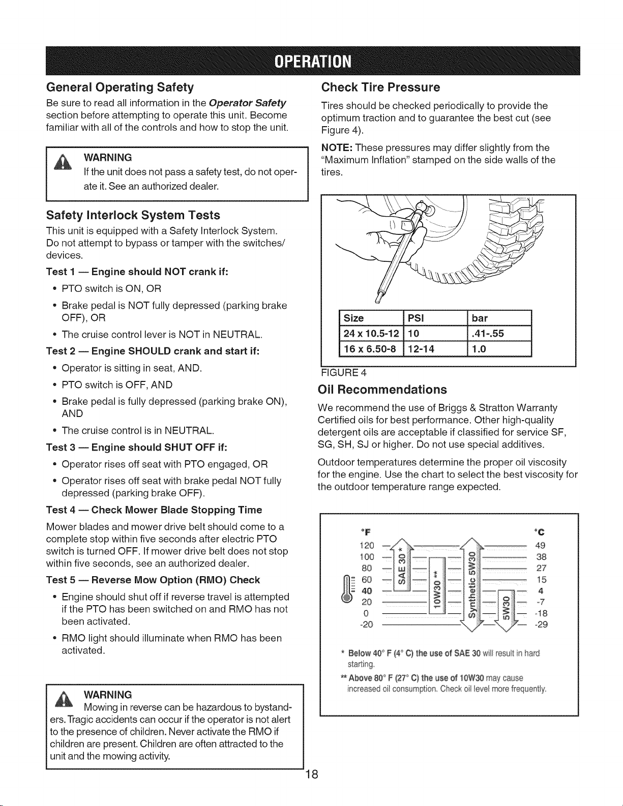
Check Tire Pressure
Tires should be checked periodically to provide the
optimum traction and to guarantee the best cut (see
Figure 4).
NOTE: These pressures may differ slightly from the
"Maximum Inflation" stamped on the side walls of the
tires.
Size PSi bar
24 x 10.5-12 10 .41-.55
16x6.50-8 12-14 1.0
FIGURE 4
Oil Recommendations
We recommend the use of Briggs & Stratton Warranty
Certified oils for best performance. Other high-quality
detergent oils are acceptable if classified for service SF,
SG, SH, SJ or higher. Do not use special additives.
Outdoor temperatures determine the proper oil viscosity
for the engine. Use the chart to select the best viscosity for
the outdoor temperature range expected.
°F
i20
_, 38
?2
4O
2O
0
-20
* Below @° F(4'_C) the #se of SAE30 willresuatn hard
staking
Above 80'_F (2T' C) the #se of 10W30maycause
increasedoil consumption Checkoi_[,eve_morefrequentty_
_ii} -7
_ q 8
°C
27
_29
18
Page 19
How to Check/Add Oil Adding Fuel
1. Remove the dipstick and wipe with a clean cloth.
2. Insert and tighten the dipstick.
3. Remove the dipstick and check the oil level. It should
be at the top of the full indicator on the dipstick.
4. If low, add oil slowly into the engine oil fill. Do not
overfill. After adding oil, wait one minute and then
recheck the oil level.
5. Replace and tighten the dipstick.
Fuel Recommendations
Fuel must meet these requirements:
• Clean, fresh, unleaded gasoline
• A minimum of 87 octane/87 AKI (91 RON). High
altitude use, see below.
• Gasoline with up to 10% ethanol (gasohol) or
up to 15% MTBE (methyl tertiary butyl ether) is
acceptable.
CAUTION: Do not use unapproved gasolines, such as
E85. Do not mix oil in gasoline or modify the engine to run
on alternate fuels. This will damage the engine compo-
nents and void the engine warranty.
To protect the fuel system from gum formation, mix a
fuel stabilizer into the fuel. See Storage. All fuel is not
the same. If starting or performance problems occur,
change the fuel providers or change brands. This engine
is certified to operate on gasoline. The emissions control
system for the engine is EM (Engine Modifications).
WARNING
Fuel and its vapors are extremely flammable
and explosive.
Fire or explosion can cause severe burns or
death.
When Adding Fuel
• Turn engine off and let engine cool at least 3
minutes before removing the fuel cap.
• Fill fuel tank outdoors or in well-ventilated area.
• Do not overfill fuel tank. To allow for expansion of
the fuel, do not fill above the bottom of the fuel tank
neck.
• Keep fuel away from sparks, open flames, pilot
lights, heat, and other ignition sources.
• Check fuel lines, tank, cap, and fittings frequently
for cracks or leaks. Replace if necessary.
• If fuel spills, wait until it evaporates before starting
engine.
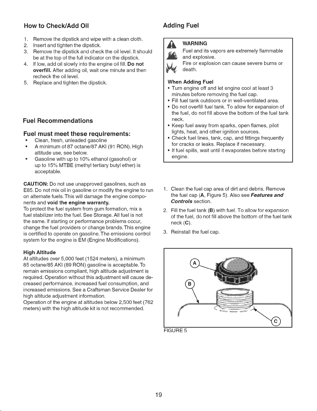
.
Clean the fuel cap area of dirt and debris. Remove
the fuel cap (A, Figure 5). Also see Features and
Controls section.
.
Fill the fuel tank (B) with fuel. To allow for expansion
of the fuel, do not fill above the bottom of the fuel tank
neck (C).
3. Reinstall the fuel cap.
High Altitude
At altitudes over 5,000 feet (1524 meters), a minimum
85 octane/85 AKI (89 RON) gasoline is acceptable. To
remain emissions compliant, high altitude adjustment is
required. Operation without this adjustment will cause de-
creased performance, increased fuel consumption, and
increased emissions. See a Craftsman Service Dealer for
high altitude adjustment information.
Operation of the engine at altitudes below 2,500 feet (762
meters) with the high altitude kit is not recommended.
FIGURE 5
19
Page 20
Starting the Engine
WARNING
Fuel and its vapors are extremely flammable
and explosive.
Fire or explosion can cause severe burns or
death.
When Starting Engine
• Ensure that spark plug, muffler, fuel cap, and air
cleaner (if equipped) are in place and secured.
• Do not crank engine with spark plug removed.
• If engine floods, set choke (if equipped) to OPEN/
RUN position, move throttle (if equipped) to FAST
position and crank until engine starts.
Driving the Tractor
1. Sit in the seat and adjust the seat so that you can
comfortably reach all the controls and see the dash-
board display.
2. Engage the parking brake.
3. Make sure the PTO switch is disengaged.
4. Start the engine (see Starting the Engine).
5. Disengage the parking brake and release the brake
pedal.
6. Depress the forward ground speed control pedal to
travel forward. Release the pedal to stop. Note that
the further down the pedal is depressed the faster the
tractor will travel.
7. Stop the tractor by releasing the ground speed control
pedals, setting the parking brake, and stopping the
engine (see Stopping the Tractor and Engine).
WARNING
Engines give off carbon monoxide, an odorless,
colorless, poison gas.
Breathing carbon monoxide can cause nausea,
fainting, or death.
Fire or explosion can cause severe burns or
_ death.
• Start and run engine outdoors.
Do not start or run engine in enclosed area, even if
doors or windows are open.
1. While sitting in the operator's seat, fully depress the
brake pedal or set the parking brake.
2. Make sure that your feet are not depressing the
ground speed control pedals and that the cruise con-
trol lever is in NEUTRAL.
3. Disengage the PTOclutch.
4. Set the throttle to FULL.
5. Insert the ignition key and turn it to START.
6. After the engine starts, move the engine throttle con-
trol to SLOW. Warm up the engine by running it for at
least a minute.
7. Set throttle to FULL.
Mowing
1. Set the mower cutting height to the desired level and
set the gauge wheels to the appropriate position (if
equipped).
2. Engage the parking brake. Make sure the PTO switch
is disengaged.
3. Start the engine (see Starting the Engine).
4. Set the throttle to FULL.
5. Engage the PTO (Mower Deck).
6. Begin mowing.
7. When finished, shut off the PTO and raise the mower
using the attachment lift control lever.
8. Stop the engine (see Stopping the Tractor and
Engine).
_ ARNING
The engine will shut off ifthe reverse ground
speed pedal is depressed while the PTO ison and
the RMO has not been activated. The operator should
always turn the PTO off prior to driving across on roads,
paths, or any area that may be used by other vehicles.
Sudden loss of drive could create a hazard.
NOTE: In the event of an emergency the engine can be
stopped by simply turning the ignition switch to STOR
Use this method only in emergency situations. For normal
engine shut down follow the procedure given in Stop-
ping the Tractor and Engine.
20
Page 21
Reverse Mowing Option (RMO TM) Stopping the Tractor and Engine
WARNING
Mowing in reverse can be hazardous to
bystanders. Tragic accidents can occur if the operator is
not alert to the presence of children. Never activate the
RMO if children are present. Children are often attracted
to the unit and the mowing activity.
The Reverse Mowing Option (RMO) allows the operator
to mow in reverse (see Features and Controls). To
activate, turn the RMO key after the PTO is engaged.
The L.E.D. light will illuminate, and the operator can then
mow in reverse. Each time the PTO is engaged the RMO
needs to be reactivated if desired. The key should be
removed to restrict access to the RMO.
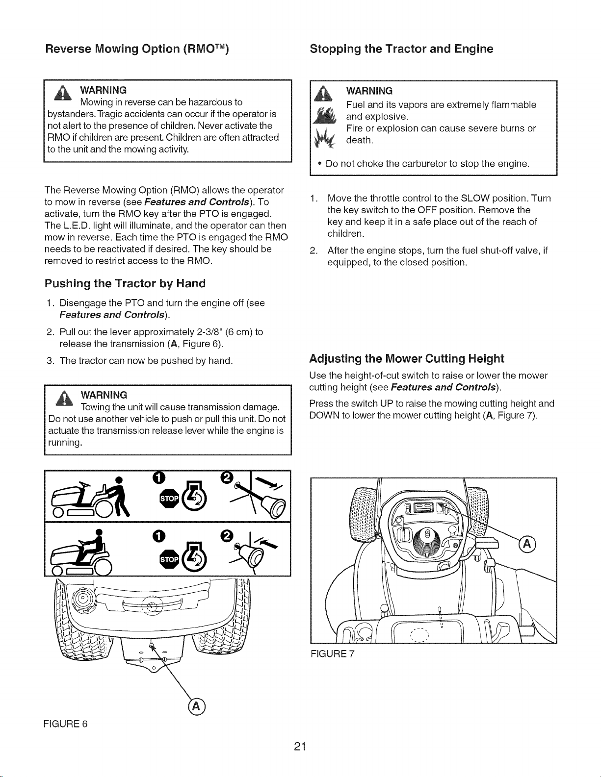
Pushing the Tractor by Hand
1. Disengage the PTO and turn the engine off (see
Features and Controls).
2. Pull out the lever approximately 2-3/8" (6 cm) to
release the transmission (A, Figure 6).
3. The tractor can now be pushed by hand.
WARNING
Towing the unit will cause transmission damage.
Do not use another vehicle to push or pull this unit. Do not
actuate the transmission release lever while the engine is
running.
WARNING
Fuel and its vapors are extremely flammable
and explosive.
Fire or explosion can cause severe burns or
death.
• Do not choke the carburetor to stop the engine.
.
Move the throttle control to the SLOW position. Turn
the key switch to the OFF position. Remove the
key and keep it in a safe place out of the reach of
children.
.
After the engine stops, turn the fuel shut-off valve, if
equipped, to the closed position.
Adjusting the Mower Cutting Height
Use the height=of=cut switch to raise or lower the mower
cutting height (see Features and Controls).
Press the switch UP to raise the mowing cutting height and
DOWN to lower the mower cutting height (A, Figure 7).
FIGURE 6
e =, I
FIGURE 7
21
Page 22
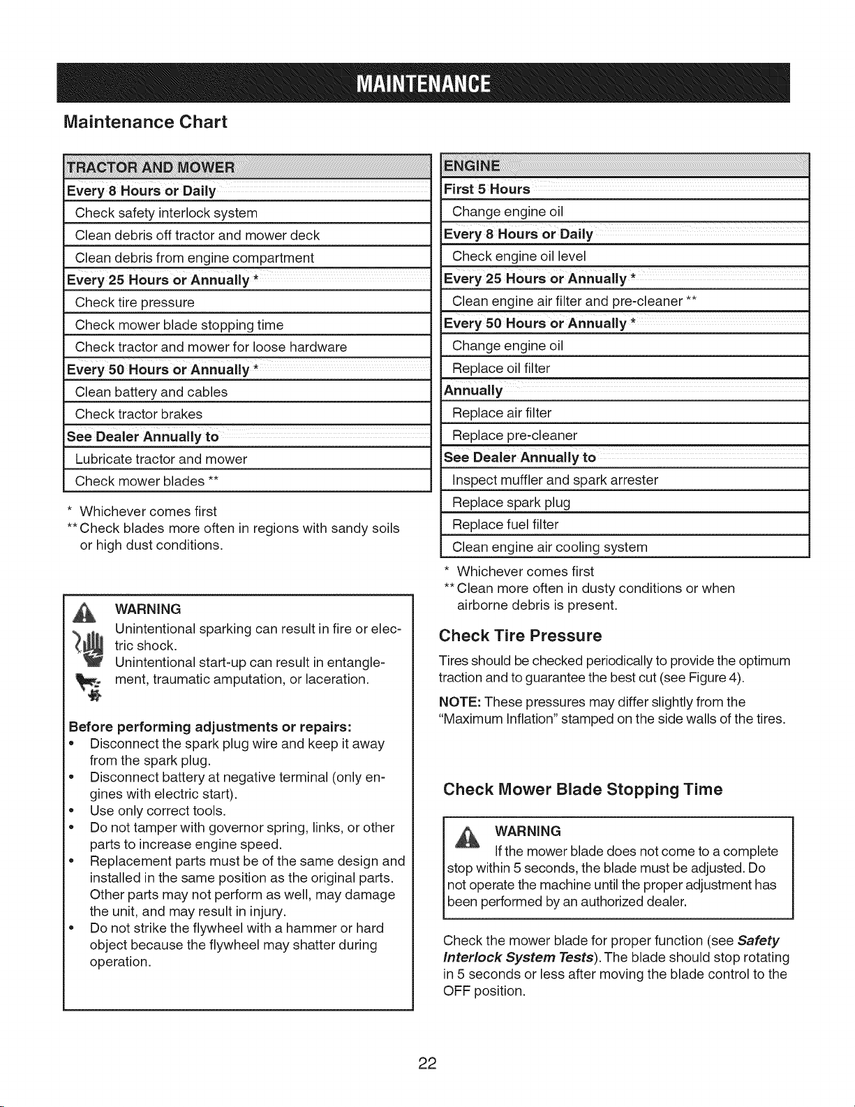
Maintenance Chart
Every 8 Hours or Daily
Check safety interlock system
Clean debris off tractor and mower deck
Clean debris from engine compartment
Every 25 Hours or Annually*
Check tire pressure
Check mower blade stopping time
Check tractor and mower for loose hardware
Every 50 Hours or Annually *
Clean battery and cables
Check tractor brakes
see Dealer Annually tO ..........
Lubricate tractor and mower
Check mower blades **
* Whichever comes first
** Check blades more often in regions with sandy soils
or high dust conditions.
WARNING
Unintentional sparking can result in fire or elec-
tric shock.
Unintentional start-up can result in entangle-
ment, traumatic amputation, or laceration.
Before performing adjustments or repairs:
• Disconnect the spark plug wire and keep it away
from the spark plug.
• Disconnect battery at negative terminal (only en-
gines with electric start).
• Use only correct tools.
• Do not tamper with governor spring, links, or other
parts to increase engine speed.
• Replacement parts must be of the same design and
installed in the same position as the original parts.
Other parts may not perform as well, may damage
the unit, and may result in injury.
• Do not strike the flywheel with a hammer or hard
object because the flywheel may shatter during
operation.
i ii !ii! ii iliiiiii ii! !!i!!i!!i!!i!......................................................................................................................................................................................................................................................................................
First 5 Hours
Change engine oil
Every 8 Hours or Daily ...........
Check engine oil level
Every 25 Hours or Annually *
Clean engine air filter and pre-cleaner **
Every 50 Hours or Annually *
Change engine oil
Replace oil filter
Annually
Replace air filter
Replace pre-cleaner
See Dealer Annually to
inspect muffler and spark arrester
Replace spark plug
Replace fuel filter
Clean engine air cooling system
• Whichever comes first
•*Clean more often in dusty conditions or when
airborne debris is present.
Check Tire Pressure
Tires should be checked periodically to provide the optimum
traction and to guarantee the best cut (see Figure 4).
NOTE: These pressures may differ slightly from the
"Maximum inflation" stamped on the side walls of the tires.
Check Mower Blade Stopping Time
WARNING
if the mower blade does not come to a complete
stop within 5 seconds, the blade must be adjusted. Do
not operate the machine until the proper adjustment has
been performed by an authorized dealer.
Check the mower blade for proper function (see Safety
interlock System Tests). The blade should stop rotating
in 5 seconds or less after moving the blade control to the
OFF position.
22
Page 23
Battery Maintenance
WARNING
A
When removing or installing battery cables,
disconnect the negative cable FIRST and recon-
nect it LAST. If not done in this order, the positive
terminal can be shorted to the frame by a tool.
WARNING
Battery posts, terminals, and related accessories
contain lead and lead compounds - chemicals known to
the State of California to cause cancer, birth defects, or
other reproductive harm. Wash hands after handling.
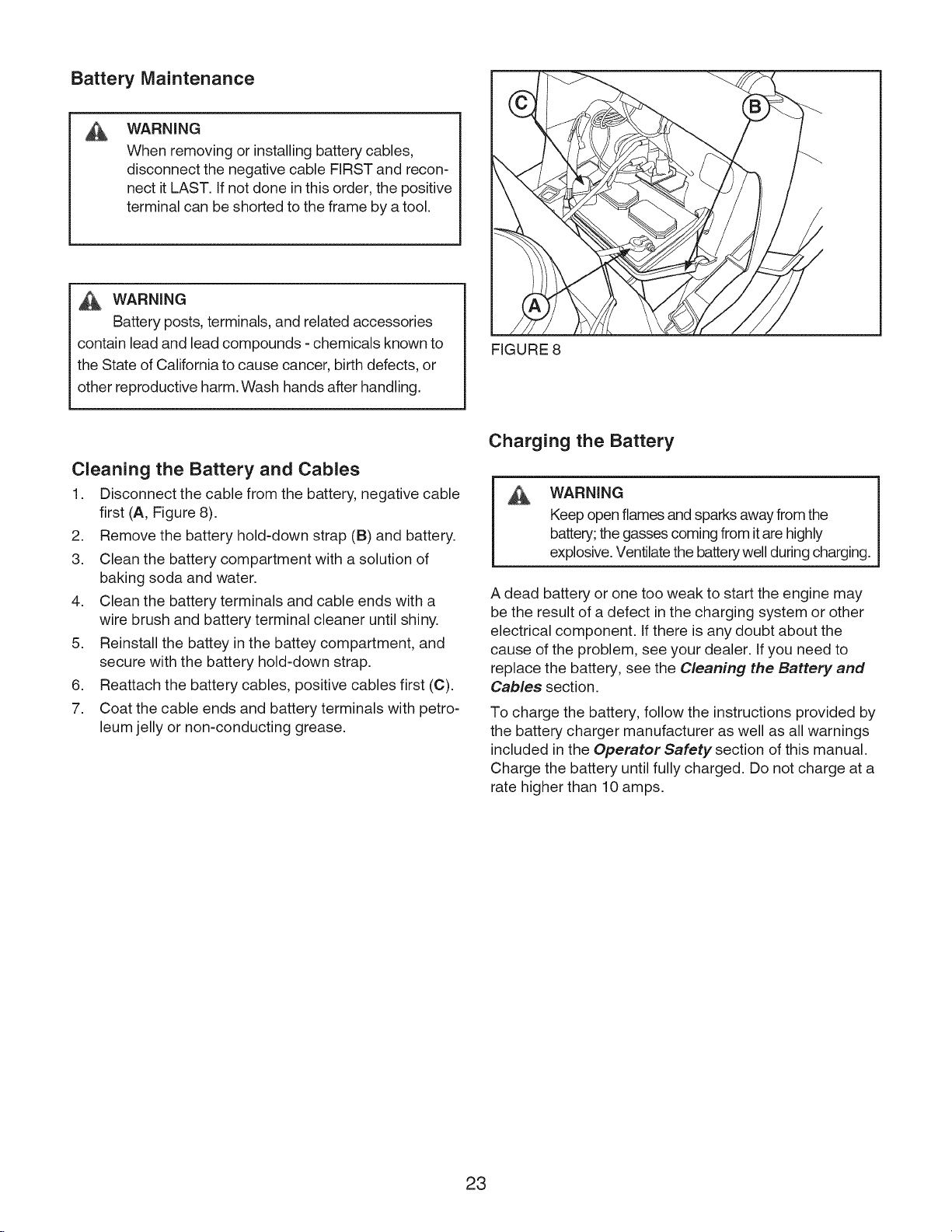
Cleaning the Battery and Cables
1. Disconnect the cable from the battery, negative cable
first (A, Figure 8).
2. Remove the battery hold-down strap (B) and battery.
3. Clean the battery compartment with a solution of
baking soda and water.
4. Clean the battery terminals and cable ends with a
wire brush and battery terminal cleaner until shiny.
5. Reinstall the battey in the battey compartment, and
secure with the battery hold-down strap.
6. Reattach the battery cables, positive cables first (C).
7. Coat the cable ends and battery terminals with petro-
leum jelly or non-conducting grease.
FIGURE 8
Charging the Battery
WARNING
Keep open flames and sparks away from the
battery;the gasses coming from itare highly
explosive. Ventilatethe battery well during charging.
A dead battery or one too weak to start the engine may
be the result of a defect in the charging system or other
electrical component. If there is any doubt about the
cause of the problem, see your dealer. If you need to
replace the battery, see the Cleaning the Battery and
Cables section.
To charge the battery, follow the instructions provided by
the battery charger manufacturer as well as all warnings
included in the Operator Safety section of this manual.
Charge the battery until fully charged. Do not charge at a
rate higher than 10 amps.
23
Page 24
Change The Oil
Used oil is a hazardous waste product and must be dis-
posed of properly. Do not discard with household waste.
Check with your local authorities, service center, or dealer
for safe disposal/recycling facilities.
Standard Oil Drain Plug
1. Remove the oil drain plug (B). Drain the oil into an
approved container.
2. After the oil has drained, install and tighten the oil
drain plug.
Remove Oil
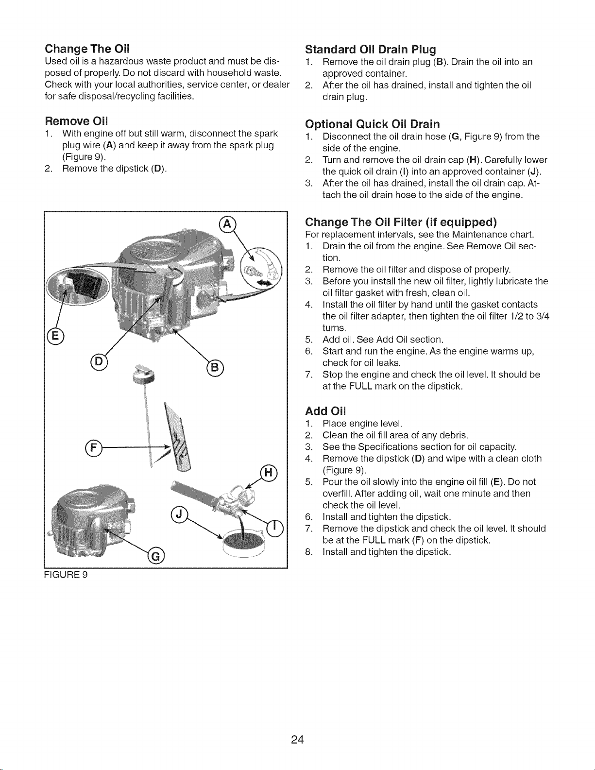
1. With engine off but still warm, disconnect the spark
plug wire (A) and keep it away from the spark plug
(Figure 9).
2. Remove the dipstick (D).
Optional Quick Oil Drain
1. Disconnect the oil drain hose (G, Figure 9) from the
side of the engine.
2. Turn and remove the oil drain cap (H). Carefully lower
the quick oil drain (I) into an approved container (J).
3. After the oil has drained, install the oil drain cap. At-
tach the oil drain hose to the side of the engine.
Change The Oil Filter (if equipped)
For replacement intervals, see the Maintenance chart.
1. Drain the oil from the engine. See Remove Oil sec-
tion.
2. Remove the oil filter and dispose of properly.
3. Before you install the new oil filter, lightly lubricate the
oil filter gasket with fresh, clean oil.
4. Install the oil filter by hand until the gasket contacts
the oil filter adapter, then tighten the oil filter 1/2 to 3/4
turns.
5. Add oil. See Add Oil section.
6. Start and run the engine. As the engine warms up,
check for oil leaks.
7. Stop the engine and check the oil level. It should be
at the FULL mark on the dipstick.
FIGURE 9
©
" ............... JJ
Add Oil
1. Place engine level.
2. Clean the oil fill area of any debris.
3. See the Specifications section for oil capacity.
4. Remove the dipstick (D) and wipe with a clean cloth
(Figure 9).
5. Pour the oil slowly into the engine oil fill (E). Do not
overfill. After adding oil, wait one minute and then
check the oil level.
6. Install and tighten the dipstick.
7. Remove the dipstick and check the oil level. It should
be at the FULL mark (F) on the dipstick.
8. Install and tighten the dipstick.
24
Page 25
Service The Air Filter Servicing the Muffler
WARNING
Fuel and its vapors are extremely flammable
and explosive.
Fire or explosion can cause severe burns or
death.
• Never start or run the engine with the air cleaner
assembly or air filter removed.
NOTICE: Do not use pressurized air or solvents to clean
the filter. Pressurized air can damage the filter and solvents
will dissolve the filter. The air filter system uses either a flat
or oval cartridge. Some models are also equipped with a
pre-cleaner that can be washed and reused.
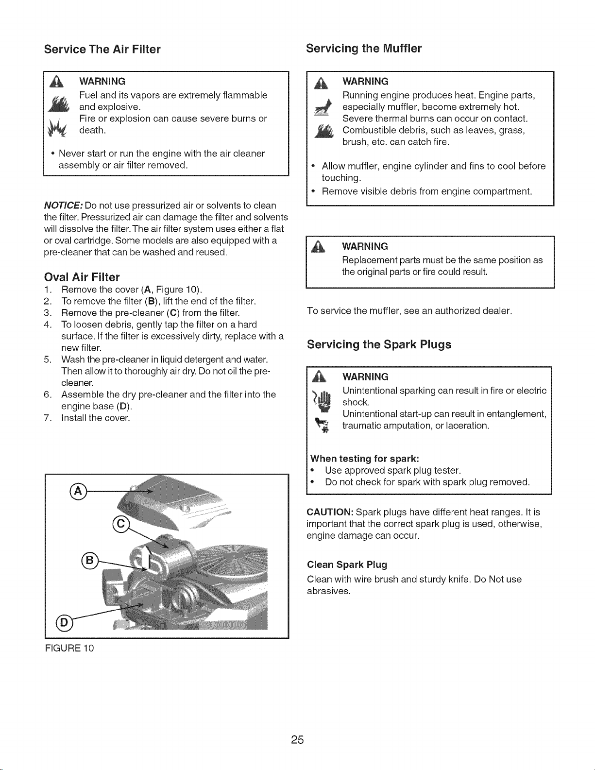
Oval Air Filter
1. Remove the cover (A, Figure 10).
2. To remove the filter (B), lift the end of the filter.
3. Remove the pre-cleaner (C) from the filter.
4. To loosen debris, gently tap the filter on a hard
surface. If the filter is excessively dirty, replace with a
new filter.
5. Wash the pre-cleaner in liquid detergent and water.
Then allow itto thoroughly air dry.Do not oil the pre-
cleaner.
6. Assemble the dry pre-cleaner and the filter into the
engine base (D).
7. Install the cover.
WARNING
Running engine produces heat. Engine parts,
especially muffler, become extremely hot.
Severe thermal burns can occur on contact.
Combustible debris, such as leaves, grass,
brush, etc. can catch fire.
Allow muffler, engine cylinder and fins to cool before
touching.
Remove visible debris from engine compartment.
WARNING
Replacement parts must be the same position as
the original parts or fire could result.
To service the muffler, see an authorized dealer.
Servicing the Spark Plugs
WARNING
Unintentional sparking can result infire or electric
shock.
Unintentional start-up can result in entanglement,
traumatic amputation, or laceration.
®
FIGURE 10
When testing for spark:
• Use approved spark plug tester.
• Do not check for spark with spark plug removed.
CAUTION: Spark plugs have different heat ranges. It is
important that the correct spark plug is used, otherwise,
engine damage can occur.
Clean Spark Plug
Clean with wire brush and sturdy knife. Do Not use
abrasives.
25
Page 26
Check Spark Plug Gap
Use a spark plug feeler gauge to check the gap between
the two electrodes. When the gap is correct, the gauge
will drag slightly as you pull it through the gap.
If necessary, use the spark plug gauge to adjust the gap
by gently bending the curved electrode without touching
the center electrode or the porcelain.
Install Spark Plug
Finger tighten, then tighten with wrench.
• 180 in-lbs (20 Nm), OR
• 1/2 turn when reinstalling the original spark plug.
1/4 turn when installing a new spark plug.
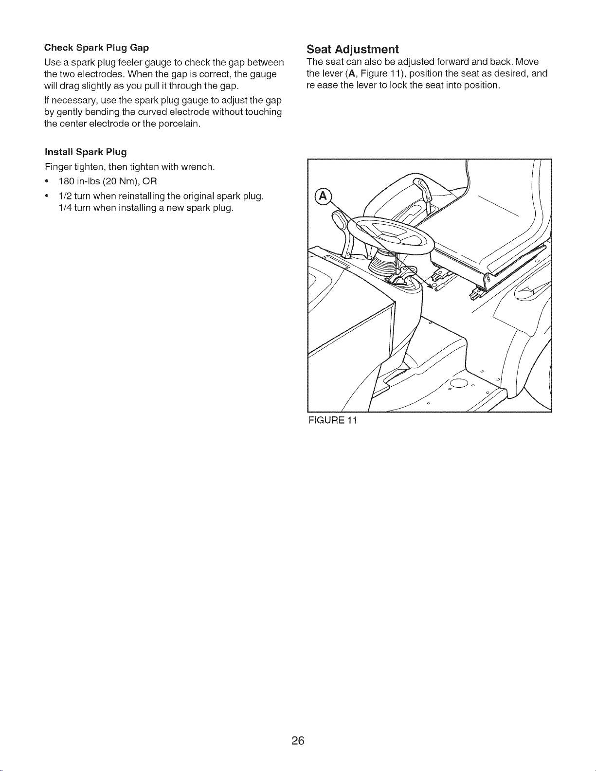
Seat Adjustment
The seat can also be adjusted forward and back. Move
the lever (A, Figure 11), position the seat as desired, and
release the lever to lock the seat into position.
FIGURE 11
26
Page 27
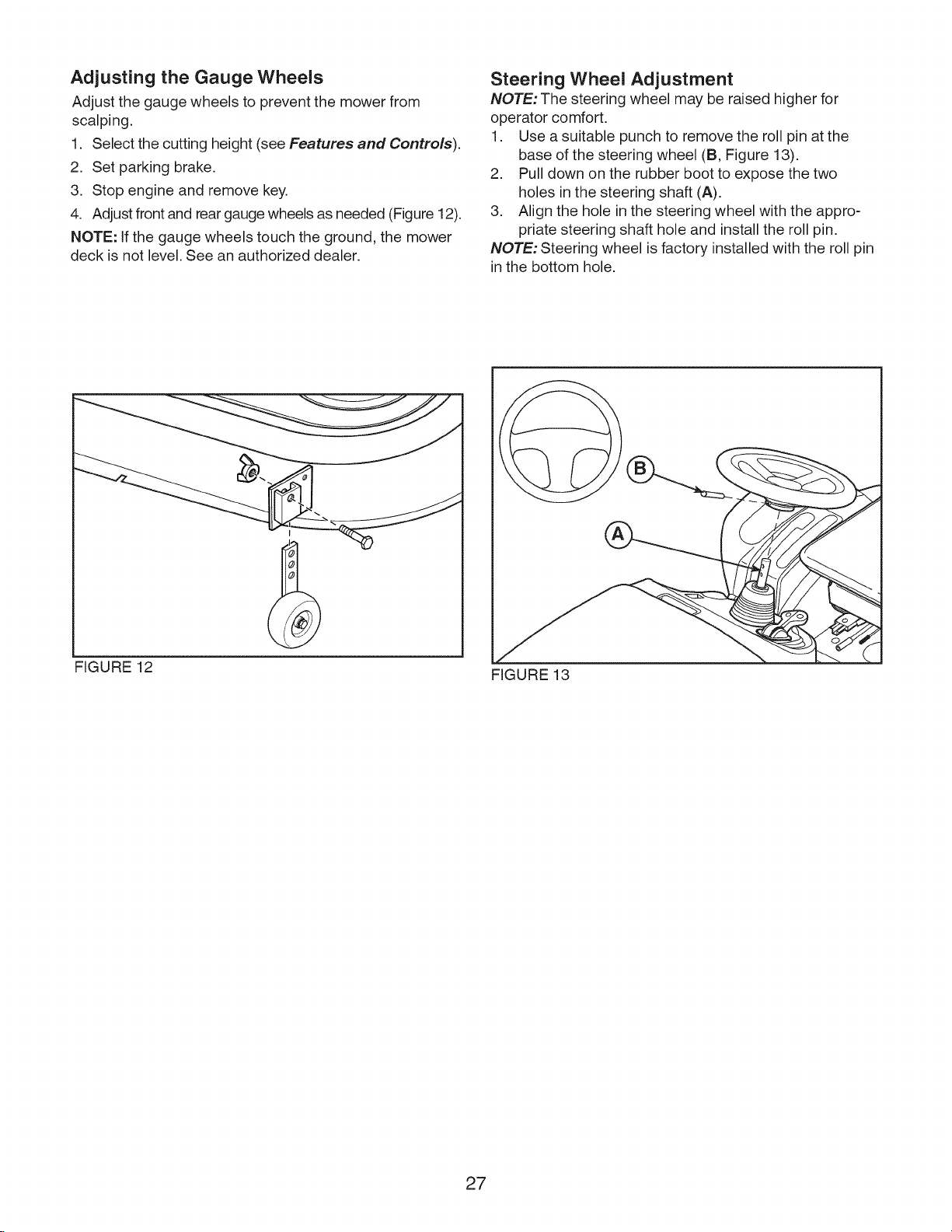
Adjusting the Gauge Wheels
Adjust the gauge wheels to prevent the mower from
scalping.
1. Select the cutting height (see Features and Controls).
2. Set parking brake.
3. Stop engine and remove key.
4. Adjust front and rear gauge wheels as needed (Figure 12).
NOTE: If the gauge wheels touch the ground, the mower
deck is not level. See an authorized dealer.
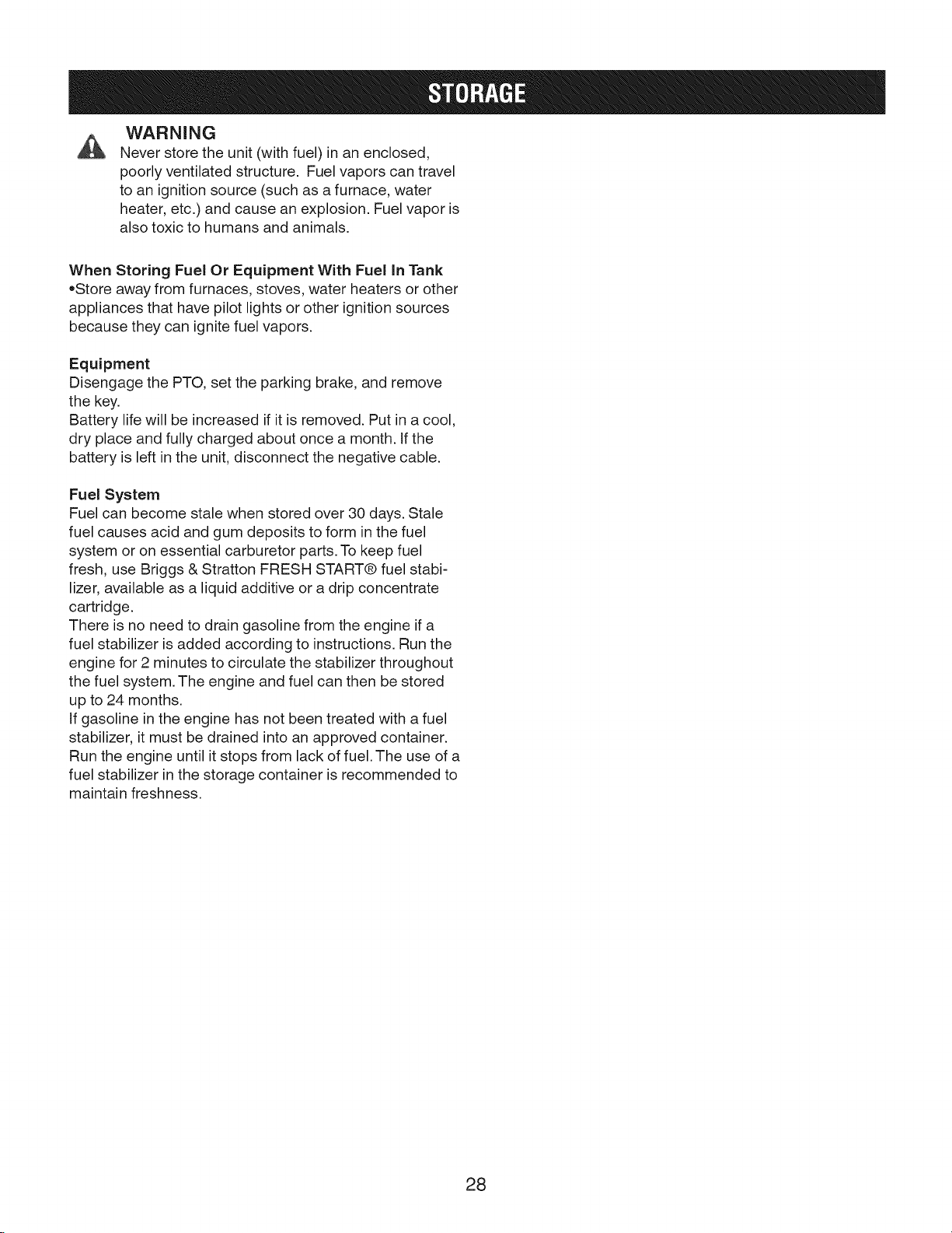
Steering Wheel Adjustment
NOTE: The steering wheel may be raised higher for
operator comfort.
1. Use a suitable punch to remove the roll pin at the
base of the steering wheel (B, Figure 13).
2. Pull down on the rubber boot to expose the two
holes in the steering shaft (A).
3. Align the hole in the steering wheel with the appro-
priate steering shaft hole and install the roll pin.
NOTE: Steering wheel is factory installed with the roll pin
in the bottom hole.
FIGURE 12
FIGURE 13
27
Page 28
WARNING
Never store the unit (with fuel) in an enclosed,
poorly ventilated structure. Fuel vapors can travel
to an ignition source (such as a furnace, water
heater, etc.) and cause an explosion. Fuel vapor is
also toxic to humans and animals.
When Storing Fuel Or Equipment With Fuel in Tank
oStore away from furnaces, stoves, water heaters or other
appliances that have pilot lights or other ignition sources
because they can ignite fuel vapors.
Equipment
Disengage the PTO, set the parking brake, and remove
the key.
Battery life will be increased if it is removed. Put in a cool,
dry place and fully charged about once a month, if the
battery is left in the unit, disconnect the negative cable.
Fuel System
Fuel can become stale when stored over 30 days. Stale
fuel causes acid and gum deposits to form in the fuel
system or on essential carburetor parts. To keep fuel
fresh, use Briggs & Stratton FRESH START@ fuel stabi-
lizer, available as a liquid additive or a drip concentrate
cartridge.
There is no need to drain gasoline from the engine if a
fuel stabilizer is added according to instructions. Run the
engine for 2 minutes to circulate the stabilizer throughout
the fuel system. The engine and fuel can then be stored
up to 24 months.
if gasoline in the engine has not been treated with a fuel
stabilizer, it must be drained into an approved container.
Run the engine until it stops from lack of fuel. The use of a
fuel stabilizer in the storage container is recommended to
maintain freshness.
28
Page 29

Troubleshooting the Tractor
PROBLEM LOOKFOR REMEDY
Brakepedalnotdepressed. Fullydepressbrakepedal.
PTO(electricclutch)switchisin PlaceinOFFposition.
ONposition.
Cruisecontrolengaged. Moveknobto NEUTRAL/OFFposition.
Outoffuel. If engineis hot,allowit tocool,thenrefill thefueltank.
Fuseis blown. Seeauthorizeddealer.
Enginewill not turnover Batteryterminalsrequire SeeCleaningthe Battery and Cablessection.
or start, cleaning.
Batterydischargedor dead. Rechargeor replacebattery.
Wiringlooseor broken. Visuallycheckwiring.Ifwiresarefrayedor broken,seeauthorizeddealer.
Solenoidor startermotorfaulty. Seeauthorizeddealer.
Safetyinterlockswitchfaulty. Seeauthorizeddealer.
Waterin fuel. Seeauthorizeddealer.
Gasisold orstale. Seeauthorizeddealer.
Enginestartshardor runs
poorly. Enginehasotherproblem. Seeauthorizeddealer.
Engineknocks.
Fuelmixturetoorich. Cleanairfilter.
Lowoil level. Check/addoil asrequired.
Usingwronggradeoil. SeeOil RecommendationsChart.
Enginerunningtoo hot. Seeauthorizeddealer.
Excessiveoil consumption. Usingwronggradeoil. See0il RecommendationsChart.
Toomuchoil in crankcase. Drainexcessoil.
Engineexhaustis black. Dirtyairfilter. SeeServicingtheAir Filter section.
Groundspeedcontrolpedals Depresspedals.
notdepressed.
Transmissionreleaseleverin MoveintoDRIVEposition.
Engine runs, but tractor will PUSHposition.
not drive. Parkingbrakeis engaged. Disengageparkingbrake.
Tractiondrivebeltisbrokenor Seeauthorizeddealer.
slipping.
Brake will not hold. Internalbrakeworn. Seeauthorizeddealer.
Steeringlinkageis loose. Seeauthorizeddealer.
Tractorsteershard or Impropertireinflation. SeeCheck Tire Pressuresection.
handlespoorly. Frontwheelspindlebearings Seeauthorizeddealer.
dry.
29
Page 30

Troubleshooting the Mower
PROBLEM LOOKFOR REMEDY
Lift linkagenotproperlyattachedSeeauthorizeddealer.
Mower will not raise, ordamaged.
Mowernotleveledproperly. Seeauthorizeddealer.
Mower cut is uneven. Tractortiresnotproperly SeeCheck Tire Pressuresection.
inflated.
Enginespeedtooslow. Setto fullthrottle.
Mower cut is rough Groundspeedtoofast. Slowdown.
looking.
Enginestalls easily with Cuttingheightsettoolow. Cuttallgrassatmaximumcuttingheightduringfirstpass.
mower engaged. Dischargechutejamming. Cutgrasswithdischargepointingtowardpreviouslycutarea.
Excessivemowervibration. Mowerhasotherproblem. Seeauthorizeddealer.
Mowerhasotherproblem. Seeauthorizeddealer.
Enginespeedtooslow. Setto fullthrottle.
Groundspeedtofast. Slowdown.
Dirtyor cloggedairfiIter. SeeServicingAir Filter section.
Enginenotuptooperating Runengineforseveralminutestowarm-up.
temperature.
Startingmowerintallgrass. Startthemowerina clearedarea.
Engineruns and tractor PTOnotengaged. EngagethePTO.
drives, but mower will not Mowerhasotherproblem. Seeauthorizeddealer.
drive.
30
Page 31

Model # 107.289850
Overall Length 75"
Overall Width 54"
Deck Size (inches) 54"
Height of Cut (infinite) 1"to 4"
Transmission Type K71 - 2WD
Tire Pressure
Front 16x8.5-8 12-14 psi
Rear 24xl 0.5-12 10 psi
Turning Radius 18"
Engine Power (hp) 30
Engine Displacement (cc) 810 cc
Fuel Tank Capacity 4 gal.
Spark Plug Gap .030"
Weight 808 Ibs.
Engine Power Rating information: The gross power rating for individual gas engine models is labeled
in accordance with SAE (Society of Automotive Engineers) code J1940 (Small Engine Power & Torque
Rating Procedure), and rating performance has been obtained and corrected in accordance with SAE
J1995 (Revision 2002-05). Torque values are derived at 3060 RPM; horsepower values are derived at 3600
RPM. Actual gross engine power will be lower and is affected by, among other things, ambient operating
conditions and engine-to-engine variability. Given both the wide array of products on which engines are
placed and the variety of environmental issues applicable to operating the equipment, the gas engine
will not develop the rated gross power when used in a given piece of power equipment (actual "on-site"
or net power). This difference is due to a variety of factors including, but not limited to, accessories (air
cleaner, exhaust, charging, cooling, carburetor, fuel pump, etc.), application limitations, ambient operating
conditions (temperature, humidity, altitude), and engine-to-engine variability. Due to manufacturing and
capacity limitations, Briggs & Stratton may substitute an engine of higher rated power for this Series engine.
31
Page 32

Your Home
For expert troubleshooting and home solutions advice:
manage
www.managemyhome.com
home
For repair - in your home - of all major brand appliances,
lawn and garden equipment, or heating and cooling systems,
no matter who made it, no matter who sold it!
For the replacement parts, accessories and
owner's manuals that you need to do-it-yourself.
For Sears professional installation of home appliances
and items like garage door openers and water heaters.
1-800-4-MY-HOME ® (1-800-4694663)
Call anytime, day or night (U.S.A. and Canada)
www.sears.com www.sears.ca
Our Home
For repair of carry-in items like vacuums, lawn equipment,
and electronics, call anytime for the location of your nearest
Sears Parts & Repair Service Center
1-800-488-1222 (U.S.A.) 1-800-469-4663 (Canada)
www.sears.com www.sears.ca
To purchase a protection agreement on a product serviced by Sears:
1-800-827-6655 (U.S.A.) 1-800-361-6665 (Canada)
Para pedir servicio de reparaci6n Au Canada pour service en fran;ais:
a domicilio, y para ordenar piezas: 1-800-LE-FOYER Mc
1-888-S U-HOGAR ® (1-800-533-6937)
(1-888-784-6427) www.sears.ca .....
® Registered Trademark / Trademark / SMService Mark of Sears Brands, LLC
® Marca Registrada / Marca de F_brica / SM Marca de Servicio de Sears Brands, LLC
MCMarque de commerce / MDMarque depos6e de Sears Brands, LLC © Sears Brands, LLC
TM
TM
32
Page 33

Manual del operador
Tractor de Jardin
Modelo N°
107.289850 PGT9500 30/54" CRAFTSMAN 2WD
Para obtener respuestas a sus preguntas
sobre este producto, Ilame al:
1-800-659-5917
Linea de ayuda de Sears Craftsman
Lunes a sAbado de 5 a.m. a 5 p.m.
Nota: Una traducci6n en espa_ol de este Manual del
Operador puede encontrarse en la pagina 33.
Sears Brands Management Corporation, Hoffman Estates, IL 60179 EE.UU.
Visite nuestro sitio Web de Craftsman: www.craftsman.com
1750727
Modificacidn A
Page 34

Gracias por haber adquirido este cortacesped CRAFTSMAN PROFESSIONAL de alta calidad. Le agradecemos
la confianza que ha depositado en la marca CRAFTSMAN PROFESSIONAL. Si usa y realiza el mantenimiento del
equipo de conformidad con las instrucciones de este manual, su producto CRAFTSMAN PROFESSIONAL le ofrecer_.
muchos aBos de funcionamiento fiable.
Este manual contiene informaci6n de seguridad para advertirle sobre los peligros y riesgos asociados con el
cortacesped y c6mo evitarlos. Este producto y sus accesorios aprobados estan diseBados solamente para cortar
cesped o retirar nieve, y no tienen otra finalidad. Es importante que lea y comprenda estas instrucciones con
detenimiento antes de proceder a arrancar o hacer funcionar este equipo. Conserve estas instrucciones originales
para consultarlas en el futuro.
D6nde encontrarnos
No tendr_tque buscarmucho para encontrarel servicio y mantenimientopara su cortacesped CRAFTSMAN. Existendistribuidores
de servicio tecnico autorizados en todo el mundo queofrecen un servicio de calidad. Puede ponerse en contactocon el Servicio al
Cliente Ilamandoal (800) 659-5917, o Iocalizar un distribuidor en lnterneten www.sears.com/craftsman.
Cortacesped
NOmerode modelo
NOmerode serie
Motor
Corte del tipo de modelo
Fecha de c6digo
Fecha de compra
Copyright © 2010
2
Page 35

NQmeros de identificaci6n
Declaraci6n de garantia
Declaraci6n de emisiones
Seguridad del operario
Caractefisticas y mandos
Operacibn
Mantenimiento
Almacenaje
Localizaci6n de fallas
Especificaciones tecnicas
Manual del operador en espaSol
'ii * iiidiiii'
IIHIT[iill!
Nombre/n_mero de descripci6n del modelo
Nhmero de inventario
Fecha de compra
3
4
5
6
8
14
18
22
29
31
33
Nhmero de sefie de la unidad
Cuando se comunique con el centro de manten=
imiento para pedir piezas de repuesto, manten=
imiento o informaci6n, el usuario DEBE tenet estos
nQmeros a su disposici6n.
Registre su nombre/numero de modelo, los numeros de
identificacion del fabricante y los numeros de serie del
motor en el espacio proporcionado para toner un acceso
f&cil.
La etiqueta de identificacion estA situada en el lado de
abajo. Incline el asiento hacia delante para acceder a la
etiqueta de identificacion.
Para obtener respuestas a sus preguntas sobre este pro-
ducto, Ilame a la linea de ayuda de Sears Craftsman en el
1-800-659-5917, de lunes a s&bado de 5 a.m. a 5 p.m.
Fabdcante del motor P!Iodelodel motor
Tipo/especiticaciones del motor Cbdigo/ntJmerode sede del motor
3
Page 36

GARANTiA COMPLETA DE FABRICACION
Cuando se opera y mantiene de acuerdo con todas las instrucciones que se proporcionan, si alguna pieza no ampli-
able de este equipo falla debido a un defecto en los materiales o en la fabricaci6n dentro de dos aSos desde la fecha
de compra, Ilame a 1-800-659-5917 para solicitar una reparaci6n gratuita en su hogar.
La cubierta y el eje delantero se repararan de manera gratuita durante cinco ahos desde la fecha de compra si se trata
de un defecto de material o de fabricaci6n.
La cobertura de la garantia anterior se aplica solo durante 90 dias desde la fecha de compra si este equipo se usa
alguna vez con prop6sitos comerciales o de arriendo.
En todos los casos, si la reparaci6n no es posible, el equipo se reemplazara de manera gratuita con el mismo modelo o
un modelo equivalente.
La bateria se reemplazara de manera gratuita durante 90 dias desde la fecha de compra si tiene defectos en los materi-
ales o en la fabricaci6n (o se comprueba que no almacena carga).
Esta garantia SOLAMENTE cubre defectos de material y fabricaci6n. Sears NO pagarb.:
• Articulos desechables que se gasten durante el uso normal, entre los que se incluyen, entre otros cuchillas, bujias,
depuradores de aire, correas y filtros de aceite.
• Servicio de mantenimiento normal, cambios de aceite o afinamientos.
• Reemplazo o reparaci6n de neumaticos debido a pinchazos pot objetos exteriores, como clavos, espinas, tocones o
vidrios.
• Reemplazo o reparaci6n de neumaticos o ruedas producto de desgaste normal, accidentes o funcionamiento o man-
tenimiento inadecuados.
• Reparaciones necesarias debido a abuso del operador, incluidos, entre otros, dahos provocados pot remolcar ob-
jetos que sobrepasen la capacidad del equipo con asiento, impactos a objetos que doblen el bastidor o cig0ehal, o
sobrepasar la velocidad del motor.
• Reparaciones necesarias debido a negligencia del operador, incluidos, entre otros, dahos electricos y mecb.nicos pro-
vocados pot almacenamiento inadecuado, no utilizar el grado ni la cantidad correcta de aceite de motor, no mantener
la cubierta libre de desperdicios inflamables o no mantener al equipo con asiento seg0n las instrucciones que se
incluyen en el manual del operador.
• Limpiezas o reparaciones al motor (sistema de combustible) provocadas pot combustible que se determine como
contaminado u oxidado (deteriorado). En general, se debe utilizar el combustible dentro de 30 dias a partir de la fecha
de compra.
• Desgaste y deterioro normal de los acabados exteriores o reemplazo de la etiqueta del producto.
Esta garantia s61ose aplica mientras este producto este dentro de los Estados Unidos.
Esta Garantia le otorga derechos legales especificos, y Ud. puede ostentar otros derechos, que pueden variar de es-
tado en estado.
Sears Brand Management Corporation, Hoffman Estates, IL 60179
4
Page 37

EmissionsControl SystemWarrantyStatement
California,UnitedStalesandCanadaEmissionsControlDefectsWarranty
Statement
TheCaliforniaAir ResourceBoard(CARB),U.S.EPAadn B&S are pleasedto explainthe
EmissionsControl SystemWarranty onyour small off-roadengine(SORE).InCalifor-
nai, newsmall off-road enginesmodelyear2006 andlatermust bedesigned,built and
equippedto meetthe State'sstrigentanti-smog standards.ElsewhereintheUnitedStates,
new non-road, spark-ignition enginescertifiedfor modelyear 1997andlatermust meet
similar standardssetforth bythe U.S.EPA.B&S must warrant the emissions control sys-
tem onyour engine for the periods oftime listedbelow,providedtherehasbeen no abuse,
neglector improper maintenanceof yoursmall off-roadengine.
Youremissionscontrol system includes parts suchas the carburetor,aircleaner,ignition
system,fuel line, muffler and catalyticconverter.Also includedmaybeconnectors and
otheremissions relatedassemblies.
Wherea warrantablecondition exists,B&Swill repair your small off-roadengineat no
cost to you including diagnosis,parts and labor.
Bfiggs & Stratton Emissions Control Defects Warranty Coverage
Small off-road engines arewarranted relative to emissions control partsdefects for a
period oftwo years, subject to provisions set forth below. If anycovered part onyour
engine isdefective, thepart will be repaired or replacedby B&S.
Thefollowing arespecific provisions relative to your Emissions Control Defects Warranty Coverage. It is in addition to the B&S engine warranty for non-regulated engines found
in the Operatingand Maintenance Instructions.
1. Warranted Parts
Coverageunder this warranty extends only to the parts listed below (the emissions
control systems parts) to the extent these parts were present on the engine
purchased.
a. FuelMetering System
. Cold start enrichment system (soft choke)
Carburetor and internal parts
, Fuel pump
Fuelline, fuel line fittings, clamps
Fueltank, cap andtether
Carbon canister
b. Air Induction System
, Air cleaner
Intake manifold
Purgeand vent line
c. Ignition System
. Spark plug(s)
Magneto ignition system
d. Catalyst System
e. Miscellaneous Items Usedin Above Systems
2. Length of Coverage
B&S warrants to the initial owner and each subsequent purchaser that the Warranted 6. Consequential Coverage
Parts shall befree from defects in materials andworkmanship which caused the Coveragehereunder shall extendto the failure of any engine components caused by
failure of the Warranted parts for a period of two years from the datethe engine is thefailure of any Warranted Partstill under warranty.
delivered to a retail purchaser.
Catalytic converter
Exhaust manifold
Air injection system or pulse valve
Vacuum, temperature, position, time sensitive valvesand switches
Connectors and assemblies
Owner's Warranty Responsibility
As thesmall off-roadengine owner,you are responsiblefor the performance ofthe required
maintenancelisted in your OperatingandMaintenanceInstructions. B&S recommends
thatyou retainallyour receiptscovering maintenanceon your small off-road engine,but
B&Scannotdenywarrantysolelyfor the lack of receiptsor for your failure to ensurethe
performanceof all scheduledmaintenance.
As thesmall off-roadengine owner,you shouldhowever be awarethat B&Smay denyyou
warrantycoverageif your small off-road engineor apart hasfaileddueto abuse,neglect,
improper maintenanceor unapprovedmodifications.
Youare responsiblefor presentingyoursmall off-road engine to an AuthorizedB&S Service
Dealerassoonasa problem exists. Theundisputedwarranty repairsshouldbe completed
in a reasonableamountof time, not to exceed30 days.
Ifyou haveanyquestions regardingyour warranty rights and responsibilities,you should
contacta B&SServiceRepresentativeat (414) 259-5262.
Theemissionswarranty isa defectswarranty. Defectsarejudgedon normal engineperfor-
mance.Thewarrantyis not relatedto an in-useemissions test.
3. No Charge
Repairor replacement of any Warranted Part will be performed at no charge to the
owner, including diagnostic labor which leadsto the determination that a War-
ranted Part is defecttive, if the diagnostic work is performed at an Authorized B&S
Service Dealeras listed in the "Yellow Pages" under "Engines, Gasoline,"" Gasoline
Engines," "Lawn Mowers," or similar category.
4. Claims and CoverageExclusions
Warranty claims shall be filed inaccordance with the provisions of the B&S Engine
Warranty Policy. Warranty coverageshall beexcluded for failures of Warranted Parts
which are not original B&S parts or because of abuse, neglect or improper main-
tenanceas set forth in the B&S Engine Warranty Policy. B&S is not liable to cover
failures of Warranted Parts caused by the use of add-on, non-original, or modified
parts.
5. Maintenance
AnyWarranted Partwhich is not scheduled for replacement as required maintenance
or which is scheduled only for regular inspection to the effect of "repair or replaceas
necessary" shall be warranted as to defects for the warranty period. Any Warranted
Partwhich is scheduled for replacementas required maintenance shall be warranted
as to defects only for the period of time up to thefirst scheduled replacementfor
that part. Any replacement part that is equivalent in performance and durability may
beused in the performance of any maintenance or repairs. Theowner is responsible
for the performance of all required maintenance, as defined in the B&S Operating
andMaintenance Instructions.
Engines that are certified to meet the California Air Resources Board (CARB) Emis-
sions Standard must display information regarding the Emissions Durability period
and theAir Index. Briggs & Stratton makes this information available to the con-
sumer on our emissions labels. The engineemissions label will indicate certification
information.
The Emissions gnrability Period describes the number of hours of actual running
time for which the engine is certified to be emissions compliant, assuming proper
maintenance in accordance wiht the Operating and Maintenance Instructions. The
following categories are used:
lVloderate:
Engine is certified to beemissions compliant for 125 hours of actual running time.
intermediate:
Engineiscertifiedto beemissionscompliantfor 250hoursofactualrunningtime.
Extended:
Engineis certified to be emissions compliant for 500 hours of actual engine running time.
For example, a typical walk-behind lawn mower is used 20 to 25 hours peryear. There-
fore, the Emissions Durability Period of an engine with an intermediate rating would
equate to 10 to 12 years.
Briggs & Stratton engines are certified to meet the United States Environmental Protec-
tion Agency (ESEPA)Phase2 emissions standards. For Phase2 certified engines, the
Emissions Compliance Period referred to onthe Emissions Compliance labelindicates the
number of operating hours for which the engine has been shown to meet Federalemis-
sions requirements.
For engines less than 225 cc displacement.
Category C= 125hours, Category B= 250 hours, Category A= 500 hours
For engines of 225 cc ormore displacement.
Category C=250 hours, Category B= 500 hours, Category A= 1000 hours
5
Page 38

Manejarelequipoconseguridad
El equipo electr6nico solamente es seguro en la medida en
Io que Io utiliza el operador. Si se utiliza de un modo incorrecto,
o no se realiza un mantenimiento correcto, ipuede ser peligroso!
Recuerde, usted es responsable de su seguridad y de aquellos que
le rodean. Utilice el sentido comQn, y piense Io que estA haciendo.
Si no esta seguro de si la tarea que va a Ilevar a cabo se puede
realizar con el equipo escogido con seguridad, pfdale consejo a un
profesionah o p6ngase en contacto con el distribuidor local.
Leael Manual
El manual del usuario contiene informaci6n de seguridad importante
que necesita conocer ANTES de manejar su unidad y MIENTRAS
la maneja.
Tecnicas de funcionamiento de seguridad, una explicaci6n de
las caracterfsticas y mandos del producto, e informaci6n sobre el
mantenimiento se incluyen para ayudarle a sacar el mejor rendimiento a
su equipo.
AsegQrese de leer totalmente la Informaci6n y Normas de seguridad
que aparecen en las siguientes paginas. Tambien lea pot completo la
secci6n de Operaci6n.
Pueden suceder accidentes trAgicos con nihos. No les permita estar
cerca del Area de operaci6n. Pot Io general los nihos se sientes
atrafdos pot la unidad y pot la actividad de cortar cesped. Nunca de pot
hecho que los ni_os vayan a permanecer en el L_ltimolugar en el que
los vio. Si hay riesgo de que los ni_os puedan entrar en la zona en la
que esta cortando el cesped, haga que otto adulto los vigile.
iNO PASEE A LOS NINOS EN ESTA UNIDAD! Esto les anima
a acercarse cerca de la unidad en un futuro mientras esta en
funcionamiento, pot Io que podrfan resultar gravemente heridos. Se
pueden acercar a la unidad para dar un paseo cuando usted no Io
espera, y los puede atropellar.
Marchaatras
No siegue en sentido contrario al normal a menos que no sea
absolutamente necesario. Mire siempre hacia abajo y hacia atras antes
y durante la marcha atras, incluso cuando se hayan desacoplado las
cuchillas del cortacesped.
Nifios
6
Page 39

Funcionamientoenpendientes
Podria lesionarse gravemente o inclusomatarse si utiliza esta unidad en
cuestas demasiado pronunciadas. El uso de la unidad en una pendiente que
es demasiado pronunciada o donde no posea la tracci6n adecuada puede
hacer que pierda el control o que vuelque.
Un buen consejo es no utilizar el cortacesped en ninguna pendiente sobre
la que no pueda ir marcha atras (en modo tracci6n a dos ruedas). No debe
usar el tractor en terrenos con una inclinaci6n superior a los 1,5 m (3,5 pies)
sobre una Iongitud de 6,0 m (20 pies). Siempre conduzca subiendo y bajando
pendientes: no de un lado a otto.
Tambien tenga en cuenta que la superficie sobre la que esta conduciendo
puede afectar en gran medida a la estabilidad y al control. La hierba hOmeda y
el pavimento helado pueden afectar gravemente su capacidad de controlar la
unidad.
Si no estb.seguro sobre c6mo operar la unidad en una pendiente, no Io haga.
No vale la pena arriesgarse.
Piezasmoviles
Este equipo tiene piezas m6viles que le pueden causar daBos a usted o
a otras personas. Sin embargo, si usted se mantiene en la posici6n del
operario, y sigue las instrucciones proporcionadas en esta manual, esta
unidad es segura.
La cubierta del cortacesped posee cuchillas en movimiento que pueden
amputar manos y pies. No permita que nadie este cerca del equipo mientras
estb. en funcionamiento.
Para ayudarle a usted, el operario, a que utilice este equipo con seguridad,
esta unidad estb. equipada con un sistema de seguridad que detecta la
presencia del usuario. NO intente alterar ni modificar el sistema. Consulte a
su distribuidor inmediatamente si el sistema no pasa todas las pruebas del
sistema de interbloqueo de seguridad que aparecen en este manual.
20
0bjet0s tirados
Esta unidad posee cuchillas en movimiento. Estas cuchillas pueden recoger
y arrojar desechos que podrfan lesionar gravemente a personas que se
encuentren en la zona. AsegOrese de limpiar la zona a sesgar ANTES de
comenzar.
No opere esta unidad sin haber instalado el recogedor de hierba o la
protecci6n posterior (deflector).
iNo permita que nadie permanezca en la zona en la que estb.manejando la
unidad! Si alguien entrase en la zona, apague inmediatamente la unidad y
espere a que se vaya.
Combustibley mantenimient0
La gasolina es extremadamente inflamable. Sus vapores tambien son
extremadamente inflamables y pueden alcanzar fuentes de ignici6n lejanas. La
gasolina solamente se puede utilizar como combustible, no como disolvente
o limpiador. Nunca debe guardarse en un lugar en el que sus vapores pueden
alcanzar una fuente de ignici6n como una luz piloto. El combustible debe
permanecer en una lata de combustible sellada o en un recipiente de pl_.stico
aprobado, o en el dep6sito de combustible del tractor con la tapa bien cerrada.
El combustible derramado ha de limpiarse inmediatamente.
Un mantenimiento adecuado es importantisimo para la seguridad y
rendimiento de su unidad. Aseg0rese de realizar los procedimientos de
mantenimiento que aparecen en este manual, y de comprobar peri6dicamente
el sistema de seguridad.
Page 40

Instrucciones de seguridad importante
CONSERVE ESTAS INSTRUCCIONES - Este manual
contiene instrucciones importantes que deberian seguir-
se durante el arranque inicial, el uso y el mantenimiento
del equipo. Conserve estas instrucciones originales
para consultarlas en el futuro.
Simbolos de seguridad y significados
FUEGO PIEZASIVIOVILES DESCABGA DETENGA
I0
VAPOBES BETBOCESO EXPLOSION
TOXICOS
UTILICE AGENTES SUPEBFICIE
PBOTECCIONES QUJIVIICOS CALIENTE
OCULARES PELIGBOSOS
ENCENDEB
APAGAB
STARTER
PELIGRO indica un peligro que, si no se Io evita,
resultar_ en muerte o lesion grave.
ADVERTENCIA indica un peligro que, si no se Io
evita, podria resultar en muerte o lesion grave.
PRECAUCION indica un peligro que, si no se
evita, podria resultar en lesion menor o moderada.
AVISO indica una situaci6n que puede provocar dahos
en el producto.
ADVERTENClA
El escape del motor de este producto contiene sus-
tancias quimicas que el estado de California sabe que
causan cancer, defectos de nacimiento u otros dahos
reproductivos.
ADVERTENClA
Algunos componentes de este producto y sus acce-
sorios relacionados contienen sustancias quimicas que
el estado de California sabe que causan cancer, defectos
de nacimiento u otros da_os reproductivos. L_.veselas
manos despues de manejar Jabateria o sus accesorios.
LEAEL
MANUAL
El simbolo de alerta de seguridad se usa para
identificar informaciOn de seguridad sobre peligros que
pueden ocasionar lesiones personales. Se usa una
palabra de sehal (PELIGRO, ADVERTENCIA o PRE-
CAUCION) con el simbolo de alerta para identificar la
probabilidad y potencial gravedad de lesiones. Ademas,
se puede usar un simbolo de peligro para representar el
tipo de peligro.
BAPIDO DESPACIO COMBUSTIBLE
ADVERTENCIA
Los bornes, las terminales de la bateria y los
accesorios de la misma contienen plomo y compuestos
de plomo, productos quimicos que el estado de Califor-
nia reconoce causar cancer, defectos de nacimiento y
otras lesiones geneticas. L_.vese las manos despues de
manejar la bateria o sus accesorios.
ADVERTENCIA
El motor expulsa monOxido de carbono, y un gas
venenoso, sin color y sin olor.
Respirar monOxido de carbono puede causar dolo-
res de cabeza, fatiga, mareos, vOmitos, confusion,
convulsiones, nauseas, desmayos o incluso la
muerte.
• Opere el equipo 0NICAMENTE al aire libre.
Evite que los gases del tubo de escape entren en un
area cerrada a traves de ventanas, puertas, tomas de
aire, u otras aberturas.
8
Page 41

I
Lea estas normas de seguridad y respetelas estrictamente. El no respetar estas normas podria resultar en
perdida del control de la unidad, lesiones personales graves o muerte para el usuario o para terceros, o
daBos en propiedades o en el equipo. La plataforma de segado puede Ilegar a amputar manos
y lanzar objetos. En el texto, el tri4ngulo_ significa precauciones o advertencias importantes que deben
seguirse.
FUNCIONAMIENTO GENERAL
1. Debera leer, comprender y seguir todas las
instrucciones que se contienen en el manual o en la
propia unidad antes de empezar a utilizarla.
2. No coloque las manos o pies cerca de componentes
giratorios ni debajo de la maquina. Mantengase lejos
en todo momento de la apertura de descarga.
3. 0nicamente adultos responsables que esten
familiarizados con las instrucciones deberan hacer
funcionar la unidad (la normativa local puede imponer
restricciones relativas a la edad del operador).
4. Despeje la zona de objetos como son piedras,
juguetes, cables, etc. Esos objetos podrian ser
cogidos y lanzados por la(s) cuchilla(s).
5. Cerci6rese de que no hay personas en la zona de
operaci6n antes de empezar a utilizar la unidad.
Detenga la unidad si alguna persona entra en la zona
de operaci6n.
6. Nunca Ileve en la unidad a nadie como pasajero.
7. No siegue en sentido contrario al normal a menos que
no sea absolutamente necesario. Mire siempre detras
y debajo antes de desplazarse hacia atras y durante
esa operaci6n.
8. No realice la descarga en ningt_n caso apuntando
hacia una persona en la operaci6n. No realice
la descarga del material contra una pared u
otros elementos obstructivos. Los materiales
pueden rebotar hacia el usuario. Detenga la(s)
cuchillas cuando cruce sobre superficies con grava.
9. No haga funcionar la maquina sin que el recogedor de
hierba, la protecci6n posterior (deflector) y los demas
dispositivos de seguridad esten en su lugar.
10. Reduzca la velocidad antes de realizar giros.
11. Nunca deje una unidad en funcionamiento sin
vigilancia. Siempre se debera desacoplar las cuchillas
(PTO), poner el freno de estacionamiento, apagar el
motor y retirar la Ilave de acceso antes de proceder a
desmontar la unidad.
12. Desacople las cuchillas (PTO) cuando no vaya a
utilizar la unidad. Apague el motor y espere hasta la
completa detenci6n de todos los componentes antes
de proceder a limpiar la ma.quina, retirar el recogedor
de hierba o desbloquear la protecci6n posterior.
13. Utilice la maquina s61ocon la luz del dia o con buena
iluminaci6n artificial.
14. No utilice la unidad mientras este bajo los efectos del
alcohol o de drogas.
15 Mantengase alerta ante el trafico cuando se halle
cerca de vias de comunicaci6n o cruce por elias.
16.Tenga especial cuidado cuando cargue o descargue
la unidad de remolques o camiones.
17. Utilice siempre protecciones oculares cuando utilice
la unidad.
18. Datos indican que operadores de 60 a_os y mas
estan involucrados en un gran porcentaje de lesiones
asociadas a equipos electricos. Estos operadores
deberan evaluar su capacidad de operar el equipo de
manera Io suficientemente segura como para evitar
lesiones, en ellos mismos o en terceros.
19.Siga las recomendaciones del fabricante sobre los
pesos y contrapesos de las ruedas.
20. Tenga presente que el operador sera el responsable
de los accidentes que puedan sufrir otras personas o
propiedades.
21. Quienes conduzcan la unidad deberan procurarse
instrucci6n practica profesional.
22. Deberan vestirse siempre calzado y pantalones
robustos. Nunca utilice la unidad con los pies
desnudos o calzando sandalias.
23. Antes de utilizar la unidad, siempre debera comprobar
visualmente que las cuchillas y los correspondientes
mecanismos estan en su sitio, intactos y bien firmes.
Sustituya los componentes gastados o daBados.
24. Desacople los elementos anexos antes de realizar
las siguientes acciones: Ilenar el dep6sito de
combustible, retirar elementos anexos o realizar
ajustes (a menos que el ajuste o ajustes puedan ser
realizados desde la posici6n del operador).
25. AI estacionar, almacenar o dejar sin vigilancia la
maquina, baje los elementos de corte, a menos que
se utilice un cierre mecanico efectivo.
26. Antes de abandonar por cualquier causa la posici6n
del operador, ponga el freno de estacionamiento (si
se tiene), desacople las cuchillas (PTO), detenga el
motor y retire la Ilave de acceso.
27. Para reducir el riesgo de incendio, mantenga la
unidad libre de hierba, hojas o exceso de lubricantes.
No detenga ni estacione la unidad sobre hojas o
hierba secas, ni sobre materiales combustibles.
TRANSPORTE Y ALMACENAIVllENTO
1. Cuando transporte la unidad sobre un remolque
abierto, cerci6rese de esterorientado hacia adelante,
en la direcci6n del viaje. Si la unidad est,. orientada en
el sentido contrario al de marcha, el empuje del viento
podria daBarla.
2. Siga siempre pr_.cticas seguras de repostaje y
manipulaci6n de combustible al cargar combustible en
la unidad despues del transporte o almacenaje.
3. Nunca guarde la unidad (con combustible) en un
lugar cerrado, o con ventilaci6n pobre. Los vapores
del combustible pueden Ilegar hasta una fuente
de ignici6n (hornos, calentadores de agua, etc.) y
producir una explosi6n. El vapor del combustible
tambien es t6xico para los humanos y los animales.
4. Siempre siga las instrucciones de manual del motor
para preparaciones para almacenaje, antes de
almacenar la unidad, tanto para periodos cortos como
largos.
5. Siempre siga las instrucciones del manual de motor
para procedimientos adecuados de arranque al
colocar la unidad nuevamente en servicio.
6. No almacene nunca la unidad o el dep6sito de
combustible en el interior de lugares en que haya
llamas expuestas o luces piloto, como es el caso
de las proximidades de un calentador de agua.
Deje que la unidad se enfrie antes de proceder a su
almacenamiento.
9
Page 42

FUNCIONAMIENTO EN PENDIENTES
Las pendientes son un factor de gran perdida en los casos
de perdida de control yen los accidentes en los que vuelca el
cortacesped, que pueden resuttar en tesiones graves o incluso
la muerte. La operaci6n en todo tipo de pendientes requiere
una precauci6n a_adida. Si no puede ir hacia atr&s sobre una
pendiente con etcortacesped o no se siente seguro sobre la
pendiente, no la utilice la unidad sobre ella.
El control de un tractor cortacesped que se deslice sobre una
pendiente no se recuperar& mediante la aplicaci6n del freno. Las
principales causas de perdida det control son: insuficiente agarre
de los neumb,ticos sobre etfirme, el exceso de vetocidad, la
apticaci6n incorrecta del freno, ta inadecuaci6n de la m&quina para
et uso concreto, la incorrecta percepci6n de lascondiciones del
piso, o el enganche o la distribuci6n de cargas incorrectos.
1. Accione el cortacesped en pendientes, en subida y bajada y
no a Io ancho.
2. Preste atenci6n ante posibles hoyos, surcos o golpes. El
terreno irregular podrfa hacer que la unidad vuetque. La
hierba alta puede ocuttar obst#,cutos.
3. Escoja una vetocidad de segado que le permita no tener que
detenerse o cambiar la velocidad mientras este recorriendo
la pendiente.
4. No utilice elcortacesped sobre hierba humeda. Los
neum_tticos poddan perder tracci6n.
5. Siempre mantenga la unidad con una marcha al bajar
las pendientes. No ponga et punto muerto para bajar por
pendientes.
6. Evite arrancar, detenerse, o girar sobre las pendientes. Si
los neumaticos pierden tracci6n, desacopte las cuchitlas y
continue lentamente en linea recta hacia abajo.
7. Todo desptazamiento en pendientes debera ser lento y
gradual. No realice cambios repentinos en lavelocidad o en
la direcci6n; la m&quina podrfa volcar.
8. Ponga la mayor atenci6n cuando haga funcionar la ma.quina
con recogedores de hierba u otros etementos acoplados;
pueden afectar a la estabilidad de la unidad. No utilice la
m&quina en pendientes pronunciadas.
9. No intente estabilizar la maquina colocando su pie sobre el
piso (en unidades en las que et conductor va montado sobre
elias).
10. No utilice el cortacesped cerca de bajadas, zanjas o
terraplenes. El cortacesped podda volcar si una rueda se
situa sobre el borde de una zanja o risco, o si el borde cede.
11. No utilice recogedores de hierba en pendientes
pronunciadas.
12. No reatice la operaci6n de segado en pendientes si no
puede ir marcha atras sobre elias.
13. Consulte a su concesionario/vendedor autorizado para
obtener recomendaciones sobre pesos y contrapesos para
las ruedas para mejorar la estabitidad.
14. Retire obstacutos como son piedras, ramas de b,rboles, etc.
15. Opere a bajas velocidades. Los neum&ticos pueden perder
traccion en pendientes incluso si los frenos funcionan
adecuadamente.
16. No realice giros en pendientes a menos que ello sea
necesario, y, en ese caso, haga giros lentos y graduales,
siempre pendiente hacia abajo si etlo es posible.
EQUIPO REMOLCADO (UNIDADES
MONTABLES)
1. Remolque solamente con una m#,quina que tenga un
enganche dise_ado para remolque. No sujete el equipo
remolcado a elementos que no sean el punto de enganche.
2. Siga las recomendaciones del fabricante en cuanto a los
limites de peso para equipos remolcados y remolque en
pendientes.
ADVERTENCIA
Nunca opere en pendientes de mas del 17,6% (10°);
esos valores equivalen a un incremento vertical de
106 cm (3-1/2 pies) en un espacio horizontal de 607
cm (20 pies).
Cuando opere en pendientes utilice pesos y
contrapesos adicionales para las ruedas. Consulte
a su concesionario/vendedor para determinar que
pesos apropiados se encuentran disponibles para su
unidad.
Seleccione una velocidad de avance lenta antes de
empezar a subir una pendiente. Adema.s de los pesos
delanteros, debe emplearse una precauci6n especial
al operar en pendientes con recogedores de hierba
de enganche posterior.
Corte el cesped SUBIENDO y BAJANDO pendientes,
nunca de un costado aotto, ponga la mayor atenci6n
3. No permita que que ni_os u otras personas se suban al
equipo remolcado.
4. Sobre las pendientes, et peso det equipo remolcado puede
causar perdida de tracci6n y perdida de control.
5. Vaya despacio y deje una distancia extra para poder parar.
6. No ponga et punto muerto para bajar por pendientes.
NI OS
Pueden ocurrir accidentes tr&gicos si el operador no est& atento
a la presencia de niSos. Los niSos suelen sentirse atraidos por la
unidad y por la actividad det cortacesped. Nunca de por hecho
que los niSos vayan a permanecer en et Ultimo lugar en et que los
rio.
1. Mantenga a los niSos fuera del &rea de corte y bajo la
vigilancia atenta de un adutto responsable.
2. Este atento y apague el equipo si entran niSos en la zona.
3. Antes y durante el avance marcha atr&s, mire atr&s y hacia
abajo para detectar la presencia de niSos.
4. Nunca Ileve niSos en la unidad, ni siquiera sin la(s)
cuchitla(s). Los niSos podrian caerse y lesionarse
gravemente, o interferir en el seguro funcionamiento de la
unidad. Los niSos que hayan montado en un cortacesped
en otros momentos pueden aparecer repentinamente en ta
zona en ta que este cortando el cesped para que los lleve y
pueden caerse o ser atropellados por la m&quina.
5. Nunca permita que niSos hagan funcionar la unidad.
6. Tenga un especial cuidado al acercarse a esquinas ciegas,
arbustos, &rboles u otros objetos que puedan dificuttar la
vision.
EMISIONES
1. El escape det motor de este producto contiene sustancias
quimicas que, en ciertas cantidades, se sabe que
causan c&ncer, defectos de nacimientos u otros da_os
reproductivos.
2. Busque informacion relevante de Periodo de Permanencia
de las Emisiones e indice en et Aire en la etiqueta sobre
emisiones del motor.
SISTEMA DE IGNICION
1. Este sistema de encendido por chispa cumple con la norma
ICEA-002 canadiense.
10
Page 43

REPARACION Y MANTENIMIENTO
Manipulaci6n segura de la gasolina
1. Apague todos los cigarrillos, puros, pipas y cualquier otra
fuente de ignici6n.
2. Utilice unicamente contenedores de gasolina homologados.
3. No retire la tapa de la gasolina ni reponga combustible con
et motor en funcionamiento. Deje que et motor se enfrfe
antes de reponer el combustible.
4. No Ilene el deposito de la m#`quina en espacios cerrados.
5. No guarde la m#`quina ni el contenedor de carburante en
lugares en los en que haya llamas expuestas, se produzcan
chispas o haya luces pilotos, como es et caso calentadores
de agua u otros dispositivos.
6. Nunca Ilene recipientes dentro de un vehicuto o sobre el
piso de un cami6n o remolque con cobertores de pl#,stico.
Siempre coloque los contenedores sobre el sueto, lejos del
vehfcuto, antes de proceder a Ilenarlos.
7. Retire det cami6n o remolque el equipamiento que se
atimente de gasolina y reponga el carburante sobre el sueto.
Si ello no es posible, entonces abastezca el vehicuto sobre
un remolque con un contenedor port#`til, no con una boquitla
de surtidor de gasolina.
8. Mantenga la boquilla en contacto con el borde de la boca
det tanque o recipiente de combustible en todo momento y
hasta haber comptetado el Ilenado. No utilice dispositivos
para bloquear y mantener abiertas boquitlas.
9. Si se derrama carburante sobre la ropa, c#`mbiese de
inmediato.
10. En ningun caso deber#` superar el Ifmite de Ilenado del
dep6sito de combustible. Vuelva a colocar la tapa det
dep6sito y ajustela firmemente.
11. Emplee la mayor precauci6n cuando manipute gasotina
uotros etementos combustibles. Los carburantes son
infiamables y sus vapores, explosivos.
12. Si se derrama combustible, no intente poner et motor en
marcha; aleje la m#`quina det #,readet derrame y evite
cualquier fuente de ignici6n hasta que se hayan disipado los
vapores del combustible.
13. Vuelva ajustar firmemente las tapas de los tanques y de los
contenedores de combustible.
ServJcio t_cnico y mantenimiento
1. Nunca haga funcionar la unidad en espacios cerrados en los
que puedan acumutarse et mon6xido de carbono.
2. Mantenga las tuercas y pernos, especialmente los pernos de
acople de las cuchillas, apretados y mantenga et equipo en
buenas condiciones.
3. Nunca fuerce los dispositivos de seguridad. Verifique
peri6dicamente su correcto funcionamiento, y realice todas
las reparaciones necesarias si no funcionan correctamente.
4. Mantenga la unidad libre de hierba, hojas u otras
acumutaciones de desechos. Limpie posibles derrames de
lubricantes o combustible y retire los desechos que puedan
resuttar impregnados de combustible. Deje que la m#`quina
se enfr[e antes de proceder a su almacenamiento.
5. Si golpea cualquier objeto con la unidad, detengase e
inspeccione la m#`quina. Antes de votver a hacer funcionar la
m#`quina, realice las reparaciones necesarias.
6. No realice ningun tipo de ajustes o reparaciones con et
motor eiq marcha.
7. Supervise con frecuencia los componentes de los
recogedores de hierba y la protecci6n posterior y,
cuando sea necesario, sustituyalos por componentes
recomendados por el fabricante.
8. Las cuchillas del cortacesped son elementos cortantes.
Retraiga la cuchitla o utilice guantes y emptee la mayor
precauci6n cuando realice operaciones de mantenimiento
en elias.
9. Verifique con frecuencia el funcionamiento de los frenos.
Haga los ajustes y reparaciones necesarios.
10. Mantenga o recambie las etiquetas de instrucciones y de
seguridad cuando sea necesario.
11. No retire el filtro de gasolina mientras el motor este caliente; la
gasolina que se derrame podrfa incendiarse. No disperse las
abrazaderas del tubo de combustible m#`sall#,de Io necesario.
Asegure firmemente las tuercas de agarre de las abrazaderas
sobre el filtro tras su instatacion.
12. No utilice gasolina que METANOL, gasohol quecontenga m#`s
de110% de ETANOL, aditivos para la gasolina, o white gas; el
motor o el sistema de atimentaci6n podrfan resuttar daSados.
13. Si el dep6sito de combustible ha de ser drenado, esa operaci6n
debe reatizarse al aire libre.
14. Reemplace los silenciadores/tapabocas defectuosos.
15. Solo use piezas de reposici6n autorizadas por la f#`bricaal hacer
reparaciones.
16. Cumpta siempre con tas especificaciones de f#`bricaen todas las
configuraciones y ajustes.
17. Unicamente se deber#`nutilizar estabtecimientos autorizados
para el mantenimiento y las reparaciones de mayor calado.
18. Nunca intente realizar reparaciones mayores en estaunidad a
no ser que tenga lacapacitaci6n necesaria. Procedimientos de
servicio incorrectos pueden resultar en funcionamiento peligroso,
da_os atequipo y anulaci6n de la garantia del fabricante.
19. En m#`quinas de cortacespedes de mOltiples cuchillas, deber#`
emptear la mayor precauci6n, ya que una cuchilla puede hacer
girar a las dem#`s.
20. No cambie los ajustes del limitador del motor ni revolucione en
exceso el motor. La operaci6n de un motor a una velocidad
excesiva puede incrementar etriesgo de que se produzcan
lesiones personales.
21. Desenganche la transmisi6n de los accesorios, detenga el
motor, retire la Ilave de acceso y desconecte elo loscables de
la bujfa antes de realizar las siguientes operaciones: despejar
obstrucciones y conductos, realizar reparaciones, tras golpear
con un objeto osi la unidad vibra anormalmente. Tras golpear
un objeto, inspeccione la m#`quinaen busca de posibles daSos
y haga las reparaciones necesarias antes de votver a porter en
marcha y hacer funcionar etequipo.
22. No coloque nunca las manos cerca de componentes m6viles,
como son elventilador de refrigeraci6n de labomba de
carburante cuando la unidad este en funcionamiento (los
ventiladores de refrigeraci6n de labomba de carburante est#`n
situadas tipicamente en taparte superior del conjunto motriz).
23. Unidades de con bombas hidr#`ulicas,mangueras o motores:
ADVERTENCIA: Los fiuidos hidr#`uticosque escapen a presi6n
puede tener fuerza suficientes para penetrar lapiel ycausar
lesiones graves. Se se inyectan fiuidos extrafios en tapiet,
deber#`nser eliminados quirergicamente en el plazo m#`ximo
de unas horas por un facuttativo que este familiarizado con esta
forma de lesiones; en caso contrario podr[a producirse un cuadro
de gangrena. Mantenga etcuerpo y las manos lejos de orificios
o boquillas de los que salgan eyectados fiuidos hidr#`uticosa
alta presi6n. Utilice papel o cart6n, no las manos, para detectar
fugas. Cerci6rese de que todas tas conexiones de los fiuidos
hidr#`ulicosest#`najustadas y que todas las mangueras y cables
se hayan en buenas condiciones antes de aplicar presi6n
sobre el sistema. Sise producen fugas, haga que la unidad
sea reparada de forma inmediata porsu centro de distribuci6n
autorizado.
24. ADVERTENCIA: Dispositivo acumulador de energ[a. La
inadecuada liberaci6n de resortes puede resuttar en graves
lesiones corporales. Los resortes deben ser retirados por un
tecnico autorizado.
25. Modelos que incluyen un radiador de motor: ADVERTENCIA:
Dispositivo acumulador de energ[a. Para evitar lesiones
corporales graves a ra[z de la exptosi6n detanticongelante o
vapor catiente, nunca intente retirar la tapa del radiador mientras
que el motor este en marcha. Detenga el motor y espere a que
se enfr[e, lnctuso despues, tenga extremo cuidado al retirar la
tapa.
11
Page 44

Po
GUIA SUGERIDA PARA EL AVISTAMIENTO DE PENDIENTES PARA
UNA OPERACION SEGURA DEL MONTABLE CON ACCESORIO
CONDUZCA SOLO HACIA ARRIBAY
HACIA ABAJO POR LA PENDIENTE
NUNCA DE UN LADO A OTRO
10 GRADOS M,AXIMO
ADVERTENCIA: Para evitar lesiones graves, opere la unidad hacia
arriba y hacia abjo por la pendiente, nunca de un lado a otro. No opere
en pendientes con una inclinaci6n mayor a 10 grados. Gire gradualmente
para evitar volcarse o perder el control. Tenga mucho cuidado al
cambiar de direcci6n en una pendiente. Los accessorios tendran un
efecto al momento de frenar. Reduzca la velocidad en las pendientes.
1.Doble la pagina a Io largo de la linea punteada como se indica arriba.
2. Sostenga la pagina frente a usted de modo que el borde izquierdo este
verticalmente paralelo al tronco de un arbol u otra estructura ventical.
3. Mire por encima del doblez en direcci6n de la pendiente que desea medir.
4. Compare el ,¢ngulo del doblez con la pendiente de la colina.
Page 45

Calcomaniasdeseguridad
Este aparato ha sido disehado y fabricado para ofrecerle
la seguridad y fiabilidad que usted esperarfa de un Ifder
de la industria en la fabricaci6n de equipos motorizados
para exterior.
Aunque la lectura de este manual y las instrucciones de
seguridad que contiene le proporcionara los conocimien-
tos bb.sicos necesarios para utilizar este equipo con
seguridad y eficacia, hemos colocado varias etiquetas
de seguridad en la unidad para recordar esta importante
informaci6n mientras esta en funcionamiento la unidad.
Todos PELIGRO, ADVERTENCIA, PRECAUCION y
mensajes de instrucci6n en elcorredor y el cortacesped
debe ser cuidadosamente lefdo y obedecido. Lesiones
personales pueden resultar cuando estas instrucciones no
son seguidas. La informaci6n es para su seguridad yes
importante! Las etiquetas de seguridad que figuran abajo
son en su jinete y segadora.
Si cualquiera de estas etiquetas se han perdido o daSado,
reemplace a la vez. Consulte a su distribuidor local para
los reemplazos.
Estas etiquetas se aplican facilmente y actuara como
un constante recordatorio visual para usted, y otros que
puedan usar el equipo, seguir las instrucciones de seguri-
dad necesarias para un funcionamiento seguro y eficaz.
Modelos de America del Norte
Decal - Instrucciones de uso, los modelos norteamerica-
nos, la pieza 1726923
Amputation
"_ Toavoidinjuryfromrotathlg
"_ blades,stayclear0f deckedg
Decal- Peligro, descarga
lateral Modelos,
Parte N o_1704276
,,/ Amputation and _"
/_ Thrown Objects Hazard /,,,"
Decal - Peligro, descarga
lateral Modelos,
Parte N o_1704277
13
Page 46

FIGURA 1
Controles del tractor
La mariposa controla la velocidad del motor. Mueva
!_Control de la mariposa
Iocidad del motor y hacia atras para disminuirla.
la mariposa hacia delante para aumentar la ve-
Siempre opere aTODA MARCHA.
_J Faros
Elinterruptorde luzenciendey apaga losfaros deltractor.
14
Opci6n de corte en marcha atr_s (RMO)
La opci6n de corte de cesped marchaatrb.s(RMO, por
sus siglas en ingles) le permite cortar cesped, o usar
otros accesorios deaccionamiento de toma de fuerza,
mientrasse mueve marcha atras. Si elige cortar el
cesped u operar otro accesorio marchaatrb.s,gire la Ilave
de opci6n de corte de cesped marcha atras despues de
accionar la toma de fuerza.La luzdel LED se encendera
y el operador podra cortar el cesped marcha atras.
Page 47

Interruptor de toma de fuerza
m
El interruptor de toma de fuerza engancha y
desengancha los accesorios que usan la toma de
fuerza. Para accionar la toma de fuerza, presione
HACIA ARRIBA en el interruptor. Presione HACIA
ABAJO para desenganchar. Tome en cuenta que
el operador debe encontrase sentado firmemente
en el asiento del tractor para que la toma de fuerza
funcione.
Interruptor de encendido
El interruptor de encendido arranca y detiene el
motor, y cuenta con tres posiciones:
_ PAGADO Detiene el motor y apaga
el sistema electrico.
_ alanca de ajuste del asiento
El asiento puede ajustarse hacia delante y hacia
atras. Mueva la palanca, coloque el asiento en la
posici6n que desee y suelte la palanca para fijar el
asiento en dicha posici6n.
Palanca de liberaci6n de la transmisi6n
palanca de liberaci6n de latransmisi6n desactiva
la transmisi6n de manera que el tractor pueda em-
pujarse manualmente. Consulte la secci6n Empuje
manual del tractor.
ENCENDIDO Permite que el motor funcione y
alimenta el sistema electrico.
l_J RRANQUE Enciende el motor para el ar-
ranque.
NOTA: Nunca deje el interruptor de encendido en
la posici6n de ENCENDIDO con el motor detenido,
ya que esto agota la bateria.
D Pedal del freno
AI presionar el pedal del freno, se activa el freno del
tractor.
H edales del acelerador
El pedal del acelerador controla la velocidad de
avance del tractor hacia delante. El pedal del acel-
erador de marcha atras controla la velocidad de
reversa del tractor.
AI presionar cualquiera de los pedales, aumentara
la velocidad de avance. Tome en cuenta que, mien-
tras mb.s presione el pedal, mas rapido avanzara el
tractor.
Freno de estacionamiento
perilla del freno de estacionamiento se usa
para bloquear el freno de estacionamiento cuando
se detiene el tractor. AI presionar por completo el
pedal del freno y al tirar hacia arriba la perilla, se
acciona el freno de estacionamiento.
C_mara de expansi6n de aceite de la
transmisi6n
Se agrega aceite de transmisi6n a traves de
la camara de expansi6n de aceite de latrans-
misi6n. Tambien sirve como capacidad adicional
del contenedor de aceite ya que al calentarse la
transmisi6n, el aceite se expande. Vea el Manual
del motor para obtener informaci6n sobre los pro-
cedimientos de medici6n de nivel y el Ilenado de
aceite.
Dep6sito de combustible
Para retirar la tapa, girela en el sentido contrario
al de las agujas del reloj. En los modelos con una
pantalla de tablero de instrumentos, el indicador
de combustible forma parte de este Oltimo. Los
modelos sin pantalla de indicador de instrumentos
tienen un indicador de combustible ubicado bajo el
asiento.
Toma corriente de 12 voltios
El tomacorriente es de 12 V CC. Los accesorios de-
ben estar clasificados para 14 amperios o menos.
_[_ Ajuste de la altura de corte del
cortac_sped
El interruptor de ajuste de la altura de corte con-
trola la altura de corte del cortacesped. La altura de
corte es infinitamente ajustable entre 2,5 y 10,2 cm
(1 pulg. y 4 pulg.).
Control de crucero
El control de crucero se usa para fijar el control
del acelerador en avance. Mueva la palanca hacia
delante hasta Ilegar a la velocidad de avance
deseada. Para desenganchar el control de crucero
mueva la palanca hacia atr_.s.Si necesita deten-
erse rapidamente, soltar el pedal de freno tambien
hara que el control de crucero vuelva a neutro.
Pedal de bloqueo del diferencial
Cuando se presiona este pedal, se bloquea el
diferencial de transmisi6n trabando ambas ruedas
traseras en "drive" (desplazamiento).
[_ Ajuste de la inclinaci6n del volante
Use la perilla de inclinaci6n ubicada en los fuelles
para liberar el mecanismo de giro y gire el volante
a la posici6n deseada. Libere la perilla de incli-
naci6n para trabarlo en esa posici6n.
15
Page 48

Pantalla y funciones del tablero de
instrumentos
Pantalla del tablero de instrumentos
Consulte la Figura 2.
A. Nivel de combustible
Indica la cantidad de combustible en el dep6sito. A la
izquierda se encuentra vacio y a la derecha se encuentra
Ileno.
B. Contador horario/Reloj/Indicador de manten =
imiento
Muestra el reloj, el contador horario y el recordatorio de
mantenimiento.
6
e
I[
information
;I;8
0
®
C. Bot6n de selecci6n
Se usa para configurar el reloj y reiniciar el recordatorio
de mantenimiento.
D. Bot6n de configuraci6n
Se usa para configurar el reloj y reiniciar el recordatorio
de mantenimiento.
E. Luz de la toma de fuerza
Indica que el interruptor de la toma de fuerza esta en la
posici6n ENCENDIDO.
F. Luz del control de crucero
Indica que el control de crucero esta activado.
G. Luz de baja presi6n del aceite
Indica que la presi6n de aceite del motor estb.baja. La luz
se enciende cuando el tractor recien se arranca y luego
se apaga. SIESTA LUZ SE ENCIENDE MIENTRAS EL
TRACTOR SE ESTA UTILIZANDO, APAGUE EL MOTOR
DE INMEDIATO. Consulte con su distribuidor autorizado
para obtener mantenimiento.
H. Luz de bajo voltaje
Indica que el voltaje del sistema electrico estb.bajo. La luz
se enciende cuando el tractor recien se arranca y luego
se apaga. SIESTA LUZ SE ENCIENDE MIENTRAS EL
TRACTOR SE EST', UTILIZANDO, APAGUE EL MOTOR
DE INMEDIATO. Consulte con su distribuidor autorizado
para obtener mantenimiento.
FIGURA 2
Funciones del tablero de instrumentos
Modelos de la pantalla del tablero de instrumentos
Mostrar el total de horas de funcionamiento: Cuando
el interruptor de la Ilave recien se gira hasta la posici6n
de ENCENDIDO, todos los indicadores de advertencia
se iluminan y se muestra el total de horas de funciona-
miento. AsegOrese de que todas las luces esten funcio-
nando.
Mostrar horas de la toma de fuerza: Gire la Ilave hasta
la posici6n de APAGADO, enganche la toma de fuerza,
y gire la Ilave hasta la posici6n de ENCENDIDO (motor
apagado).
Configurar el reloj: Arranque el motor y dejelo en fun-
cionamiento. Presione el bot6n de selecci6n (C, Figura 2)
por tres (3) segundos y sueltelo. Mantenga PRESlONA-
DO el bot6n de configuraci6n (D) para avanzar el tiempo.
Presione el bot6n de selecci6n para seleccionar los
minutos. Mantenga PRESlONADO el bot6n de configu-
raci6n (D) para avanzar el tiempo. Sueltelo por 5 segun-
dos y el reloj se activar& Apague el motor.
Modo de demostraci6n: Con el motor apagado, man-
tenga presionado el bot6n de configuraci6n (D) y gire el
interruptor de la Ilave hasta la posici6n de ENCENDIDO.
Recordatorio de mantenimiento: Se muestra un recor-
datorio de mantenimiento en la ventana de informaci6n
(B) luego de las primeras 5 horas de operaci6n y luego
cada 50 horas. El recordatorio se reinicia automatica-
mente luego de 5 horas. El recordatorio se puede reini-
ciar manualmente al girar el interruptor de la Ilave desde
la posici6n APAGADO hasta la posici6n ENCENDIDO
(con el motor apagado) y luego presionando los botones
de configuraci6n (D) y de selecci6n (C) al mismo tiempo
por 5 segundos.
16
Page 49

Freno de estacionamiento
Utilice el control del freno de estacionamiento para
accionar o desactivar el freno de estacionamiento
cuando el tractor este detenido (ver Caracterfsticas y
controles).
Accionamiento del freno de estacionamiento -
Para accionar el freno de estacionamiento, presione
el pedal del freno a fondo, tire del control del freno de
estacionamiento HAClA ARRIBA y suelte el pedal del
freno.
Desactivaci6n del freno de estacionamiento - Para
desactivar el freno de estacionamiento, presione el
pedal del freno a fondo, presione el control del freno de
estacionamiento HACIA ABAJO y suelte el pedal del
freno.
Tomacorriente de 12 voltios
El enchufe auxiliar de 12 voltios se ubica en el receptacu-
Io lateral izquierdo. Puede usarse para alimentar disposi-
tivos electr6nicos pequeSos. Los accesorios deben estar
clasificados para 9 amperios o menos.
NOTA: Hacer funcionar un accesorio de 12 voltios, en
especial con el motor en marcha lent& puede provocar la
descarga de la baterfa. Cuando no se use el enchufe aux-
iliar, debe cubrirse con el tap6n de goma a fin de evitar
que la humedad provoque un cortocircuito. El ingreso de
agua al interior del enchufe puede provocar un cortocir-
cuito.
FIGURA 3
Tracci6n de control automatico
&Qu_ es la tracci6n de control autom_tico?
La tracci6n de control automatico (ACT, por sus siglas
en ingles) es una funci6n exclusiva de nuestras transmi-
siones que brinda una tracci6n mejorada. La ACT aplica
una torsi6n uniforme preestablecida a ambas ruedas
si una de elias comienza a resbalar (una transmisi6n
sin ACT perdera la tracci6n por completo si una rueda
trasera comienza a resbalar). Esta torsi6n preestablecida
es suficiente para brindar tracci6n adicional y aun as[
permitir que las ruedas giren a distintas velocidades en
un giro pronunciado sin dahar el cortacesped.
Que se puede esperar de su tractor
con ACT
La mayorfa del tiempo no notara que la ACT esta trabajando
mientras este usando su tractor y simplemente se acostum-
brara a la tracci6n aumentada que brinda una transmisi6n
ACT.
En algunos casos se puede exceder el Ifmite del sistema
ACT y una de las ruedas traseras puede resbalar (por ejem-
plo, si intenta subir una cuesta mientras acelera). Esto es
normal. Si comienza a perder tracci6n, no acelere. En lugar
de eso, disminuya la velocidad hasta detenerse, enderece
el volante y acelere lentamente. La detenci6n del tractor
permite que la transmisi6n recupere mas tracci6n.
17
Page 50

Consideraciones generales de seguridad
de funcionamiento
Asegurese de leer toda la informaci6n en la secci6n $eguridad
del usuario antes de intentar utilizar esta unidad. Famitiarfcese
con todos los controles y con et modo de detener la unidad.
_, ADVERTENCIA
Si la unidad no pasa con _xito algOn test de seguridad,
no la ponga en funcionamiento. Consutte a un distribui-
dor autorizado.
Pruebas del sistema de interbloqueo de
seguridad
Esta unidad est& equipada con un Sistema de interbloqueo
de seguridad. No intente modificar niforzar los interruptores/
dispositivos.
Test 1 = El motor NO debeHa girar si:
• El interruptor de PTO esta. en posici6n ON (Encendido), O
Si NO se presiona completamente et pedal (freno de
estacionamiento no activado),
La palanca de controlador de velocidad de crucero NO se
encuentra en la posici6n NEUTRAL.
Test 2 = El motor DEBERJA girar y ponerse en marcha sJ:
El operador estersentado en el asiento, Y
El interruptor de PTO est#, en posici6n OFF (Apagado), Y
El pedal de freno se presiona completamente (freno de
estacionamiento activado), Y
La palanca de controlador de vetocidad de crucero se
encuentra en la posici6n NEUTRAL.
Test 3 = El motor deberl'a APAGARSE si:
El operador levanta et asiento con et PTO acoplado, O
El operador se levanta del asiento con el pedal det freno NO
completamente presionado (freno de estacionamiento no
activado).
Test 4 -- Revisar el tiempo de detenci6n de la cuchilla del
cortacesped
Las cuchitlas de la segadora y la banda de transmisi6n de la
segadora deben detenerse completamente en cinco segundos
despues de que se APAGUE el interruptor electrico det PTO. Si
la correa de transmision no se detiene antes de transcurridos
5 segundos, consutte a su agente autorizado local.
Test 5 -- Comprobaci6n de la opci6n de cortar el cesped
marcha atras (RMO)
• El motor debeda apagarse si se intenta la marcha atra.s, si
se ha activado PTO, y no se ha activado la opci6n de cortar
et cesped marcha atra.s.
• La luz de opci6n de cortar et cesped marcha atr&s se
deberia encender cuando se activa dicha opci6n.
Compruebe la presi6n de los neumaticos
Los neum_tticos se deben comprobar regutarmente para
obtener 6ptima tracci6n y garantizar et mejor corte (vease
Figura 4).
NOTA: Estas presiones pueden diferir ligeramente del infiado
m&ximo ("Maximum Inflation") que consta impreso en la
superficie lateral de los neum&ticos.
Size PSi bar
24 x 12-12 10 .41-.55
16x6.50-8 12-14 1.0
FIGURA4
Recomendaciones para el aceite
Recomendamos usar aceites certificados con garantia de
Briggs & Stratton para Iograr el mejor rendimiento. Tambien
se pueden usar aceites detergente de alta calidad si estb,n
clasificados para el servicio SF, SG, SH, SJ o superior. No
utilice aditivos especiales.
Las temperaturas exteriores determinan ta viscosidad correcta
del aceite para el motor. Use la tabla para seleccionar la mejor
viscosidad para et rango de temperaturas exteriores esperadas.
°F
i20 -- : ....... ,
'0'0'0O
_20
._!!_ 38
_i 27
_iiiiii
_iii} !
_!_ i -18
°C
49
_29
ADVERTENCIA
Etcorte marcha atras puede ser peligro para los
transe0ntes. Pueden ocurrir accidentes graves si el usuario no
esta atento ante lapresencia de niSos. Nunca active la RMO
en presencia de niSos. Los niSos suelen sentirse atraidos por la
unidad y por la actividad del cortac_sped.
18
Page 51

Verifique y agregue el aceite del motor
1. Coloque et tractor sobre una superficie lisa.
2. Detenga et motor y retire la Ilave de acceso.
3. Limpie y retire cualquier suciedad que exista en et &rea de
Ilenado del aceite.
4. Retire la varilla para medir et nivet de aceite y limpiela con
un paso limpio.
5. lnserte por completo la varilla para medir et nivel de aceite.
6. Saque la varilla y compruebe el nivel del aceite. Debe estar
en la marca de FULL (Lleno) de la varilla.
7. Siest& FULL (Lleno), inserte la varilla de medir y ajusteta
firmemente.
Si ester LLENO, inserte la varilla y aprietela bien. Si est&
BAJO et nivet de aceite, agregue aceite lentamente dentro
del tubo de Ilenado de aceite de motor (ver Reeomenda-
clones para el ace#e). No 1oIlene en exceso. Despues de
haber agregado aceite, espere un minuto y luego verifique
et nivel del aceite.
ASadir combustible
ADVERTENCIA
El combustible y sus vapores son extremamente
inflamables y exptosivos.
El fuego o las exptosiones pueden causar
quemaduras graves o incluso la muerte.
Cuando arranque el motor
• AsegOrese que la bujia, el silenciador, la tapa de Ilenado
de combustible (si se tiene) y et fittro de aire esten
colocados y fijos en su lugar.
• No encienda et motor con la bujia desenchufada.
• Si el motor se desborda, coloque et estrangutador (sise
tiene) en ta posici6n OPEN/RUN (Abrir/Marcha), coloque
et acelerador en FAST (R&pido) y gire et motor hasta que
arranque.
Recomendaciones para combustible
El combustible debe cumplir estos requisitos:
• Gasolina frescaysin plomo.
• Un minimo de 87 octanos/87 AKI (91 RON).
• La gasolina con un m#,ximo de110% de etanol (gasohol)
o un m&ximo det 15% de MTBE (acetato de metileter de
propilengticol).
PRECAUClON: No utilice gasolinas no homologadas, como
es el caso de E85. No haga mezclas con las gasolina ni realice
modificaciones en el motor para hacerlo funcionar con otros
combustibles. Hacer tal cosa daSaria los componentes del
motor y anularfa la garantl'a del motor.
Para proteger elsistema de combustible de la formaci6n
de resinas, mezcle un estabitizador de combustible en et
combustible. Consulte la secci6n Almacenaje. No todos
los combustibles son iguales. Si tiene problemas durante el
arranque o el funcionamiento, cambie de proveedor o marca de
combustible. El funcionamiento de este motor con gasolina est&
certificado. Et sistema de control de emisiones para este motor
es EM (Modificaciones de motores).
1. Limpie el &rea de la tapa del tanque de combustible. Retire
la tapa del dep6sito de combustible (A, Figura 5). Consutte
tambien la secci6n Caracterfsticas y controles.
2. Llene el deposito de combustible (B) con combustible. Para
permitir que el combustible se expanda, no lleve el dep6sito
por encima de la parte inferior del cuello del tanque de
combustible (C).
3. Vuelva a instalar la tapa del combustible.
FIGURA 5
19
Page 52

Arranque del motor
ADVERTENCIA
Et combustible y sus vapores son extremamente
infiamables y exptosivos.
El fuego o las explosiones pueden causar
quemaduras graves o incluso la muerte.
Cuando arranque el motor
• AsegOrese que la buj[a, el silenciador, la tapa de Ilenado
de combustible (si se tiene) y et fittro de aire esten
colocados y fijos en su lugar.
No encienda el motor con la buj[a desenchufada.
Si el motor se desborda, coloque et estrangutador (si se
tiene) en la posici6n OPEN/RUN (Abrir/Marcha), coloque
et acelerador en FAST (R&pido) y gire et motor hasta que
arranque.
ADVERTENClA
Et motor exputsa mon6xido de carbono, y un gas
venenoso, sin color y sin olor.
Respirar mon6xido de carbono puede causar n&u-
seas, mareos o incluso la muerte.
El fuego o las explosiones pueden causar quemadu-
ras graves o incluso la muerte.
Arranque el motor y dejelo en marcha en exteriores.
No arranque et motor ni Io deje en marcha en &reas
cerradas, aunque haya puertas o ventanas abiertas.
1. Sentado en el asiento del operador, presione el pedal
del freno a fondo o engrane el freno de estaciona-
miento.
2. AsegOrese que sus pies no presionen los pedales
de control de velocidad de desplazamiento y que la
palanca de control de crucero este en neutral.
3. Desengrane el embrague del PTO.
4. Coloque el acelerador en PLENO.
5. NOTA: Posiblemente, el motor caliente no requiera el
uso del estrangulador.
6. Inserte la Ilave de ignici6n y gfrela a ARRANCAR.
7. Despues de que el motor haya arrancado, mueva el
control de acelerador del motor a LENTO. Caliente el
motor dejandolo en marcha durante por Io menos un
minuto.
8. Coloque el acelerador en PLENO.
NOTA: En el caso de una emergencia, se puede de-
tener el motor simplemente girando el interruptor de la
ignici6n a PARAR. Use este metodo s61o en situaciones
de emergencia. Para apagar el motor normalmente siga
el procedimiento proporcionado en Detenci6n del tractor
y el motor.
Conducci6n del tractor
1. Situese en el asiento y ajusteto a fin de que pueda
atcanzar todos los controles y ver la pantalla det tabtero
c6modamente (vease Caracter[sticas y controles).
2. Accione el freno de mano. Presione et pedal del freno a
fondo, tire et control del freno de estacionamiento HACIA
ARRIBA y suelte et pedal del freno.
3. Compruebe que el interruptor PTO este desengranado.
4. Ponga en marcha et motor (vease Arranque de! motor).
5. Desacopte et freno de estacionamiento. Presione el
pedal del freno a fondo, presione et control del freno de
estacionamiento HACIA ABAJO y suelte et pedal det freno.
6. Presione el acelerador para permitir el avance. Libere el
pedal para detenerse. Note que cuanto m&s se presione et
pedal, el tractor avanzar& con mas rapidez.
7. Detenga el tractor sottando los pedates que controlan la
velocidad de avance del tractor, colocando el freno de
estacionamiento, y deteniendo el motor (vease CSmo
detener el tractor y el motor).
Cortar el cesped
1. Ajuste la altura de corte del cortacesped en et nivel
deseado utilizando et interruptor de altura de corte (ver
Caracterfsticas y controles).
2. Accione el freno de mano. Asegurese que et interruptor de
la toma de fuerza este desengranada.
3. Arranque et motor (vea CSmo arrancar el motor).
4. Coloque et acelerador en la posici6n FULL (Lleno).
5. Accione la toma de fuerza para activar las l&minas del
cortacesped.
6. Desactive et freno de estacionamiento y comience a cortar
et cesped.
7. Cuando termine de cortar et cesped, apague et PTO.
8. Presione el bot6n de arranque para DETENER et motor
(vease Cdmo detener el tractor y el motor).
ADVERTENCIA
Et motor se apagar_t si se encuentra presionado el
3edat de acelerador de reversa mientras que PTO se encuentra
activado y aQnno se ha activado la opci6n de cortar el c_sped
marcha atr_ts.Et operador siempre deber[a apagar el PTO
antes de conducir en cattes, rutas, o cualquier area que sea uti-
lizada por otros vehiculos. La p@dida de conducci6n repentina
3odr[a convertirse en un riesgo.
20
Page 53

Opci6n de corte en marcha arras (RMO TM) C6mo detener el tractor y el motor
,_ ADVERTENCIA
Etcorte marcha atras puede ser peligro para los
transeQntes. Pueden ocurrir accidentes graves si el usuario no
esta atento ante lapresencia de niSos. Nunca active la RMO
en presencia de niSos. Los niSos suelen sentirse atraidos por la
unidad y por la actividad del cortac_sped.
La opci6n de cortar el cesped en marcha atr&s (RMO)
permite al operador sesgar el cesped marcha atr&s (vease
Caracteristicas y mandos). Para activar, gire la Ilave de
opci6n de corte marcha atr&s despues de acoplar PTO. Se
encender& la luz det LED y, a continuaci6n, el usuario podr&
cortar marcha atr&s. Cada vez que se acople PTO, puede
reactivar la opci6n de corte marcha atr&s, si Iodesea. Se
deberfa retirar la Ilave para restringir et acceso a la opci6n de
cortar et cesped en marcha atr&s.
Empujar el tractor cortacesped
manualmente
1. Desacopte el PTO y apague el motor (vease
Caracterfsticas y controles).
2. Levante la palanca 6 cm (2-3/8 putg.) aproximadamente
para liberar la transmision (A, vease Figura 6).
3. Es ahora que puede empujarse et tractor manualmente.
ADVERTENCIA
El combustible y sus vapores son extremamente infia-
mables y explosivos.
El fuego o las explosiones pueden causar quemaduras
graves o incluso la muerte.
• No cebe et carburador para detener et motor.
1. Sentado en el asiento del operador, presione el pedal
del freno a fondo o engrane el freno de estaciona-
miento.
2. AsegOrese que sus pies no presionen los pedales
de control de velocidad de desplazamiento y que la
palanca de control de crucero este en neutral.
3. Desengrane el embrague del PTO.
4. Coloque el acelerador en PLENO.
5. Cierre el estrangulador.
NOTA: Posiblemente, el motor caliente no requiera el uso
del estrangulador.
_L, ADVERTENCIA
Remotcar launidad causaria daSos en la transmisi6n.
No utilice ningQn tipo de vehicuto para empujar o tirar de la uni-
dad. No utilice la palanca de liberaci6n de transmisi6n mientras
el motor est_ en funcionamiento.
• 0
Ajuste de la altura de corte del cortacesped
Utilice et interruptor de altura de corte para aumentar o reducir
la altura de corte del cortacesped (vease Caracter(sticas y
controles).
Presione el interruptor hacia ARRIBA para etevar ta altura de
corte de cesped y hacia ABAJO para bajar laaltura.
FIGURA 7
FIGURA 6
21
Page 54

Cuadro de iVlantenirniento
i i ! !!i! i i i !iiiiiiiii iii ii iiii iiii iiii iiii iiii iiii iiii iiii iiii iiii iiii iiii iiii iiii iiii iiii iiii iiii iiii iiii iiii iiii iiii iiii iiii iiii iiii iiii iiii iiii iiii iiii iiii iiii iiii iiii iiii iiii iiii iiii iiii iiii iiii iiii iiii iiii
Cada 8 horas odiariarnente
Revise el sistema de interbloqueo de seguridad
Limpie los desechos del tractor y de la plataforma del
cortacesged
Limpie los desechos del compartimiento del motor
Carla 25 horas o anualmente *
Revise la presi6n de los neumaticos
Revise el tiempo de detenci6n de las cuchillas del corta-
_ed
Revise las piezas metalicas sueltas en el tractor yen el
cortacesped
Carla 50 horas o anualmente *
Limpie la bater[a y los cables
Revise los frenos del tractor
m
Consulte al distribuidor anualmente para
Lubricar el tractor y el cortacesped
Revisar las cuchillas del cortacesped **
*Lo que suceda primero
**Revise las cuchillas mas a menudo en regiones con condiciones de suelos
arenosos o con mucha cantidad de polvo.
Verificaci6n de la presi6n de los neurnati-
cos
La presi6n de los neuma.ticos se debe revisar en forma
peri6dica y mantenerse en los niveles que aparecen en
la tabla. Tome en cuenta que dichas presiones pueden
tener leves diferencias con respecto al "inflado maximo"
que aparece en la cara lateral de los neumaticos. Las
presiones mostradas proporcionan la tracci6n adecuada,
mejoran la calidad del corte y prolongan la vida Qtildel
neumatico.
i i !6 !! ! i! i! i! i! i! ! !i i! i i ii ii ii ii ii ii ii ii ii i i i !i i iii i!i i!i!iiiiiiiiiiiiiiiiiiiiiiiiiiiiiiiiiiiiiiiiiiiiiiiiiiiiiiiiiiiiiiiiiiiiiiiiiiiiiiiiiiiiiiiiiiiiiiiiiiiiiiiii ii! iii ! i i ! i i i!!i!i i!! i !i!!iiiii!i!ii !!!! ! ! ii!! !! !!!!! !ii!i !i !!! !!!! !i ! !i! ! ! ! i! ii i i iii!iiii ! i ii i i iiii i i i i iiiiiiii i i ii iiiiiiii i i ii iiiiiiii i i ii iiiiiiii i i ii iiiiiiii i i ii iiiiiiii i i ii iiiiiiii i i ii iiiiiiii i i ii iiiiiiii i i ii iiiiiiii i i ii iiiiiiii i i ii iiiiiiii i i ii iiiiiiii i i ii iiiiiiii i i ii iiiiiiii i i ii iiiiiiii i i ii iiiiiiii i i ii iiiiiiii i i ii i iiii i i i i i ! ! ! ! y !J:!
Prirneras 5 horas
Cambie el aceite del motor
Carla 8 horas o diariarnente
Revise el nivel de aceite del motor
Carla 25 horas o anualmente *
Limpie el filtro y el predepurador de aire del motor **
Carla 50 horas o anualmente *
Cambie el aceite del motor
Cambie el filtro de aceite
Anualmente
Cambie el filtro de aire
Cambie el predepurador de aire
Consulte al distribuidor anualmente para
Inspeccionar el silenciador y el amortiguador de chispas
Reemplazar la bujfa
Reemplazar el filtro de combustible
Limpiar el sistema de refrigeraci6n de aire del motor
*Lo que suceda primero
**Limpie mas a menudo en condiciones polvorientas o cuando hayan
desechos transportados pot el aire.
Revise el tiernpo de detenci6n de las
cuchillas del cortacesped
Las cuchillas y la correa de transmisi6n del cortacesped
deben detenerse completamente dentro de cinco se-
gundos luego de apagar el interruptor de toma de fuerza
electrico.
1. Con el tractor en neutro, la toma de fuerza desacti-
vada y el operador en el asiento, arranque el motor.
2. Revise el reposapies de la izquierda en la correa
de transmisi6n del cortacesped. Accione la toma
de fuerza y espere algunos segundos. Desactive la
toma de fuerza y verifique la cantidad de tiempo que
demora la correa de transmisi6n en detenerse.
3. Si la correa de transmisi6n del cortacesped no se
detiene en cinco segundos, vuelva a ajustar el em-
brague o consulte con su distribuidor.
:T
22
Page 55

ADVERTENCIA
Cuando retire o instale los cables de la bateria,
desconecte el cable negativo EN PRIMER LUGAR
y reconectelo EN 0LTIMO LUGAR, ya que, si no
Io hace en este orden, el terminal positivo puede
hacer cortocircuito al tocar el chasis con una her-
ramienta.
ADVERTENClA
Los bornes, las terminales de la bateria y los
accesorios de la misma contienen plomo y compuestos
de plomo, productos quimicos que el estado de Califor-
nia reconoce causar cancer, defectos de nacimiento y
otras lesiones geneticas. LAvese las manos despues de
manejar la bateria o sus accesorios.
FIGURA 8
Limpieza de la bateria y de los cables
1. Desconecte los cables de la bateria, primero el cable
negativo (A, Figura 8).
2. Retire la sujeci6n de la bateria (B) y esta L_ltima.
3. Limpie el compartimiento de la bateria con una solu-
ci6n de bicarbonato de sodio y agua.
4. Limpie los terminales y extremos de cables de la
bateria con un cepillo de alambre y con un limpiador
especializado hasta que esten brillantes.
5. Vuelva a instalar la bateria en el compartimiento de la
bateria y fijela con la sujeci6n.
6. Vuelva a conectar los cables de la bateria, el cable
positivo primero (C).
7. Cubra los extremos del cable y los terminales de la
bateria con vaselina o con grasa aislante.
Carga de la bateria
ADVERTENCIA
Mantenga las llamas expuestas y las chispas lejos
de la bateria; los gases que provienen de esta son
altamente explosivos. Ventile en forma correcta la
bateria durante la carga.
Una bateria muerta o con poca carga para arrancar el
motor puede ser el resultado de un defecto en el sistema
de carga u otros componentes electricos. Si tiene alguna
duda con respecto al origen del problema, consulte con
su distribuidor. Si necesita cambiar la bateria, consulte la
secci6n Limpieza de la bateria y de los cables.
Para cargar la bateria, siga las instrucciones que brinda
el fabricante del cargador de la bateria y tambien todas
las advertencias que se incluyen en la secci6n Seguri-
dad del usuario de este manual. Cargue la bateria hasta
que este cargada completamente. Pero no Io haga a una
velocidad mayor que 10 amperios.
23
Page 56

C6mo cambiar el aceite
El aceite usado es un producto de desecho peligroso y
debe ser desechado en forma apropiada. No Iodescarte
con la basura de la casa. Verifique con sus autoridades
locales, con el centro de servicio, o con su distribuidor
para obtener informaci6n acercade las instalaciones para
su destrucci6n/reciclaje seguros.
Remoci6n del Aceite
1. Con el motor apagado pero ann caliente, desconecte
el cable de la bujia (A) y mantengalo a distancia de la
bujia (Figura 9).
2. Retire la varilla indicadora de nivel de aceite (D).
Tap6n de drenaje de aceite estandar
1.Remueva el tap6n de drenaje de aceite (B). Drene el
aceite en un recipiente
aprobado.
®
®
@
FIGURA 9
Nota: Cualquiera de los tapones de drenaje de aceite
mostrados a continuaci6n puede estar instalado en el
motor.
2. Despues de haber drenado el aceite del motor, instale
y apriete el tap6n de drenaje de aceite.
Tap6n de drenaje de aceite opcional
1. Desconecte la manguera de drenaje de aceite (G,
Figura 14) del lado del motor.
2. Gire y retire la tapa de drenaje del aceite (H). Cui-
dadosamente haga descender el drenaje rapido del
aceite(I) a un recipiente aprobado (J).
3. Despues de drenar el aceite, coloque y apriete la tapa
de drenaje de aceite. Fije a la manguera de drenaje del
aceite al lado del motor.
Cambie el Filtro de Aceite (si est,_ equi-
pado)
Para saber carla cu_nto requiere set reemplazado,
consulte el cuadro de
Mantenirniento.
1. Drene el aceite del motor. Consulte la secci6n Remo-
ci6n del Aceite.
2. Remueva el filtro de aceite y desechelo de manera
adecuada. Vea la Figura 14.
3. Antes de instalar el nuevo filtro de aceite, lubrique un
poco el empaque del filtro de aceite con aceite fresco y
limpio.
4. Instale manualmente el filtro de aceite de hasta que
el empaque haga contacto con el adaptador del filtro de
aceite, luego apriete el filtro de aceite dandole 1/2 a 3/4
de giro.
5. ABada aceite. Consulte la secci6n Aprovisionamiento
de Aceite.
6. De arranque y opere el motor. A medida que el motor
se caliente compruebe si hay fugas de aceite.
7. Detenga el motor y compruebe el nivel de aceite. El
nivel de aceite debe alcanzar la marca FULL en la varilla
indicadora de nivel de aceite.
Aprovisionarniento de Aceite
• Coloque el motor a nivel.
• Limpie el area de Ilenado de aceite de todo desecho.
Consulte la secci6n de Especificaciones para la capaci-
dad de aceite.
1. Remueva la varilla indicadora de nivel de aceite (D) y
limpiela con un trapo limpio (Figura 14).
2. Vierta el aceite lentamente pot dentro del tubo de
Ilenado de aceite (E). No Io Ilene excesivamente.
Despues de aprovisionar con aceite, espere un minuto y
vuelva a comprobar el nivel de aceite.
3. Coloque y ajuste la varilla indicadora.
4. Remueva la varilla indicadora de nivel de aceite y com-
pruebe el nivel de aceite en la varilla. El nivel de aceite
debe alcanzar la marca FULL (F) en la varilla indicadora
de nivel de aceite.
5. Coloque y ajuste la varilla indicadora.
24
Page 57

C6mo mantener el filtro de aire Mantenimiento del silenciador
ADVERTENCIA
El combustible y sus vapores son extremada-
mente inflamables y explosivos.
Un incendio o una explosi6n pueden causar
graves quemaduras o lamuerte.
• Nunca arranque L_opere el motor si removi6 el
conjunto del filtro de aire o el filtro de aire.
NOTIFICACION: No use aire a presi6n ni solventes para
limpiar el filtro. El aire a presi6n puede daBar el filtro y los
solventes pueden disolverlo. El sistema del filtro de aire
utiliza un cartucho piano u ovalado. Algunos modelos
tambien incluyen un pre-filtro que se puede lavar y utilizar
de nuevo.
Filtro de Aire
1.Retire la cubierta (A, Figura 10).
2. Remueva el filtro (C) y el pre-filtro (B).
3. Para aflojar los desechos, golpee suavemente el filtro
sobre una superficie dura. Si el filtro esta excesivamente
sucio, reemplacelo con un nuevo filtro.
4. Lave el pre-filtro en detergente liquido y agua. Luego
permita que se seque completamente al aire. No aceite el
pre-filtro.
5. Instale el pre-filtro seco y el filtro sobre la base del mo-
tor (D).
6. Instale la tapa.
®
ADVERTENCIA
El motor en marcha produce calor. Las piezas
del motor, especialmente el silenciador, se vuel-
ven sumamente calientes.
Se pueden producir quemaduras t@micas gra-
ves al contacto.
Detritos del combustible, tales como hojas, ces-
ped, maleza, etc., pueden incendiarse.
Permita que el silenciador, el cilindro y las aletas del
motor se enfrien antes de tocarlos.
Limpie los desechos visibles del compartimiento del
motor.
ADVERTENCIA
Las piezas de reemplazo deben estar en la
misma posici6n que las piezas originales o puede
originarse un incendio.
Para el mantenimiento del silenciador, consulte a un dis-
tribuidor autorizado.
Mantenimiento de las bujias
ADVERTENCIA
Las chispas no deseadas pueden causar un
incendio o una descarga electrica.
El arranque no intencional pueden resultar en
enmaraSamiento, amputaci6n traumatica o
laceraci6n.
FIGURA 10
AI realizar pruebas de chispas:
• Use un probador de bujias aprobado.
• No realice la prueba de chispas sin la bujia coloca-
da.
PRECAUClONES: Las bujias poseen distintos rangos
de calor. Es importante utilizar la bujia apropiada, de otro
modo, podria daBarse el motor.
Limpieza de la bujia
Limpie con un cepillo de alambre y un cuchillo resistente.
NO utilice abrasivos.
25
Page 58

Comprobaci6n de ia abertura de la bujia
Utilice un calibre de espesor de bujfas para comprobar el
espacio entre los dos electrodos. Cuando el espacio es
correcto, el calibre se arrastrara ligeramente hasta que
pase por el espacio.
Si es necesario, utilice el calibre de bujfa para ajustar el
espacio doblando suavemente el electrodo curvado sin
tocar el electrodo central o la porcelana.
[nstalaci6n de la bujia
Primero aprietela con los dedos y, a continuaci6n, con
una Ilave mecanica.
• 20 Nm (180 pulg.-Ibs), O
media vuelta al reinstalar la bujfa original.o cuarto de
vuelta al instalar una bujfa nueva.
Ajuste del asiento
El asiento puede ajustarse hacia delante y hacia atr&s.
Mueva la palanca (A, Figura 11), coloque el asiento en
la posici6n que desee y suelte la palanca para fijar el
asiento.
FIGURA 11
26
Page 59

Ajustar las ruedas reguladoras
Ajustar las ruedas de medici6n para evitar que el corta-
cesped realice cortes rasantes.
1. Seleccione la altura de corte (vease Caracter(sticas
y controles).
2. Coloque el freno de estacionamiento.
3. Pare el motor y retirar la Ilave.
4. Ajuste las ruedas reguladoras delanteras y traseras
segQn sea necesario (vease Figura 12).
NOTA: Si las ruedas reguladoras tocan el suelo, la pla-
taforma del cortacesped no esta nivelada. Consulte a un
distribuidor autorizado.
Ajuste del volante
1. Use un punz6n adecuado para retirar el pivote de
rodillo (A, Figura 13) en la base del volante (B).
2. Tire hacia abajo la funda de goma para exponer los
dos orificios en el b.rbol de la direcci6n (C).
3. Alinee el orificio en el volante con el orificio cor-
respondiente en el arbol de la direcci6n e instale el
pivote de rodillo.
NOTA" El volante se instala en fabrica con el pivote de
rodillo en el orificio inferior.
FIGURE 12
FIGURA 13
27
Page 60

AImacenaje
ADVERTENCIA
Nunca almacene la unidad (con combustible) en
una estructura cerrada y con poca ventilaci6n. Los
vapores del combustible pueden trasladarse a
una fuente de ignici6n (tal como una caldera, un
calentador de agua, etc.) y causar una explosi6n.
El vapor del combustible tambien es t6xico para
seres humanos y animales.
AI almacenar combustible o equipos con combus-
tible en el tanque
Almacenar lejos de calderas, estufas, calentadores de
agua u otros aparatos con luces-piloto u otras fuentes de
ignici6n, ya que pueden prender fuego a vapores de la
gasolina.
Equipo
Desengrane el PTO, desengrane el freno de estaciona-
miento y retire la Ilave.
La vida L_tilde la bateria sera superior si se la retira.
Col6quelo en un lugar fresco y seco y carguelo por com-
pleto alrededor de una vez al mes. Si se deja la bateria
en la unidad, desconecte el cable negativo.
Sistema de combustible
El combustible puede echarse a perder cuando se Io al-
macena mas de 30 dias. El combustible echado a perder
provoca la formaci6n de dep6sitos de acido y goma en el
sistema de combustible o en piezas esenciales del car-
burador. Para mantener fresco el combustible, utilice el
estabilizador de combustible FRESH START@ de Briggs
& Stratton disponible como aditivo liquido o cartucho
concentrado de goteo.
No es necesario drenar la gasolina del motor si se
agrega un estabilizador de combustible de acuerdo
con las instrucciones. Ponga en marcha el motor por 2
minutos para circular el estabilizador por todo el sistema
de combustible. Luego, se puede almacenar el motor y
el combustible por hasta 24 meses. Si no se ha tratado
a la gasolina en el motor con un estabilizador de com-
bustible, se Io debe drenar en un recipiente aprobado.
Ponga en marcha el motor hasta que se detenga por falta
de combustible. Se recomienda el uso de un estabiliza-
dor de combustible en el recipiente de almacenaje para
mantener la frescura.
28
Page 61

Resoluci6n de problemas en el tractor
PROBLEMA BUSQUE SOLUCION
IEIpedaldelfrenoest_oprimido. Levanteel piecompletamentedelpedaldefreno.
l ElinterrupterdelPTO(embragueelectrico)SitOeloenla posiciOnAPAGADO.
l est_enla posiciOnENCENDIDO.
ControladordevelocidadenacciOn. Muevael cebadoraposiciOnNEUTRAL/APAGADO.
l Nohaycombustible. Si el motorest_caliente,esperea queseenfrfey luegorepongaelcombustibledel
tanque.
Motorahogado. Desacopleelestrangulador.
l Elfusibleest_quemado. Consulteaundistribuidorautorizado.
Losterminalesdelabaterfarequieren ConsultelasecciOnLimpieza de la baterfa y de/cableado.
jEJmotor no gira o limpieza.
arranca.
jEI motor no
arranca bien o no
funcionabien. l Elmotortieneotroproblema. Consultea undistribuidorautorizado.
lEl motor da UtilizaciOndelubricantedegrade ConsulteTabladerecomendaciones de aceite.
golpes, incorrecto.
Excesivo consume UtilizaciOndelubricantedegrade ConsulteTabladerecomendaciones de aceite.
de lubricante, incorrecto.
l Labaterfaest_descargadao agotada. Recargueo sustituyalabaterfa.
l Elcableadoest_desaflojadoo rote. Inspeccionevisualmenteel cableado.Si loscablesest_ndeshilachadoso rotes,
consulteaundistribuidorautorizado.
Solenoideo starterdefectuosos. Consultea undistribuidorautorizado.
l Interrupterdeinterbloqueodeseguridad Consultea undistribuidorautorizado.
defectuoso.
Presenciadeaguaenelcombustible. Consultea undistribuidorautorizado.
Elcombustibleesviejoo sehaechadoa Consultea undistribuidorautorizado.
i perder.
Lamezcladecombustibleesdemasiado Limpieel filtro delaire.
rica.
l Bajoniveldelubricante. Compruebeyen sucaserepongael lubricante.
Elmotorsecalientademasiadoal Consultea undistribuidorautorizado.
funcionaL
Excesodelubricanteenel carter. Droneelexcesodelubricante.
lEltube de escape lElfiltrodelaireest_sucio. ConsultelasecciOnMantenimientode/filtro de aire.
iest_ enneorecido. Estranguladorcerrado. Abraelestrangulador.
j Lospedalesdecontroldevelocidadno se Piselospedales.
i hanpisado.
i EImotor arranca,
i peroel tractor no
avanza. Frenodeestacionamientopuesto. Quiteelfrenodeestacionamiento.
PalancadeliberaciOndelatransmisiOnen C_mbielaa laposiciOnIMPULSAR.
laposiciOnEMPUJAR.
JLacorreadetransmisiOndetracciOnest_ Consultea undistribuidorautorizado.
rotao resbala.
29
Page 62

Resoluci6n de problemas en el tractor (continuaci6n)
PROBLEIVlA BUSQUE SOLUCION
El frenonose Elfrenointernoest_desgastado. Consulteaun distribuidorautorizado.
sostiene.
LaconexiOndeladirecciOnest_ Consulteaundistribuidorautorizado.
El tractoroira desaflojada.
o maniobra Infladoincorrectodelosneum_ticos, iConsultelasecciOnComprobar la presidn de los neumdticos.
de manera
insuficiente. Loscojinetesdelasruedasdelanteras Consulteaun distribuidorautorizado.
Resoluci6n de problemas en el cortacesped
PROBLEMA BUSQUE SOLUCIOH
EI cortacespedno ElacopledeelevaciOnnoest_conectado Consulteaun distribuidorautorizado.
se eleva, correctamenteoest_da_ado.
El corteque hace equilibrado.
el cortacespedes Losneum_ticosdeltractornoest_n ConsultelasecciOnComprobarla presi6n de los neumdticos.
desigual, infladoscorrectamente.
El corteque hace lenta.
el cortacesped Lavelocidaddetierraes demasiado iDisminuyalavelocidad.
tiene unaspecto r_pida.
basto.
El motor se atasca Elfiltrodelaireest_suciouobstruido. Consultelasecci6nMantenimiento de/filtro de aire.
f_cilmentecon el Alturadecortedemasiadobaja. Cortelahierbaaltaconlamaximaalturaenlaprimerapasada.
cortac6speden
marcha. Conductodedescargaatascado. Hierbacortadacon ladescargaapuntandohaciaunaunazonacortadapreviamente.
Demasiada Elcortacespedtieneotro problema. Consulteaun distribuidorautorizado.
vibraci6nen el
cortac_sped.
El motor arranca
y el tractorse
desplaza,pete el Elcortacespedtieneotroproblema. Consulteaun distribuidorautorizado.
tractornoavanza.
est_nsecos.
Elcortacespednoadecuadamente iConsulteaun distribuidorautorizado.
Lavelocidaddelmotoresdemasiado JConfigurelavelocidadal m_ximodelestrangulador.
Elcortacespedtieneotroproblema. Consulteaun distribuidorautorizado.
Lavelocidaddelmotoresdemasiado JConfigurelavelocidadal m_ximodelestrangulador.
lenta.
Lavelocidaddetierraesdemasiador_pida.JDisminuyalavelocidad.
Motorno preparadoparalatemperatura JPermitaqueelmotorfuncionevariosminutosparaquesecaliente.
operativa.
Arranquedelcortacespedenhierbaalta. iArranqueel motorenunazonadespejada.
ElPTOnoest_embragado. JEmbragueel PTO.
30
Page 63

Model # 107.289850
Largo total 75"
Ancho total 54"
Cubierta tamaSo (inches) 54"
Altura de corte 1"- 4"
Trasmission tipo K71 - 2WD
Presi6n en las llantas
Frente 16×6.5-8 12-14 psi
Trasero 24×10.5-12 10 psi
Caballos de fuerza (hp) 30
Desplazamiento (cc) 810 cc
Capacidad del dep6sito de combustible 4 gal.
Entrehierro Inducido .030"
Peso 808 Ibs.
Informaci6n de clasificaci6n de potencia del motor
La clasificacion de potencia bruta para el modelo de motor de gasolina individual esta etiquetada de acuerdo con el codigo J1940
(Small Engine Power & Torque Rating Procedure) de la SAE (Society of Automotive Engineers), y la clasificacion de rendimiento ha
sido obtenida y corregida de conformidad con SAE J 1995 (Revision 2002-05) Los valores de fuerzas de torsion han sido obtenidos a
3060 rpm; los valores de caballos de fuerza han sido obtenidos a 3600 rpm. La potencia bruta efectiva del motor resultara disminuida
y se verb afectada por, entre otros elementos, las condiciones ambientales de funcionamiento y variabilidad entre motores.
Dado el amplio conjunto de productos en que se colocan los motores y la variedad de cuestiones ambientales relevantes para el
funcionamiento del equipo, el motor de gasolina no desarrollara la potencia bruta clasificada cuando se utilice en un componente
de equipamiento motorizado determinado (potencia del motor efectiva in situ e neta). Estas diferencias son debidas a una amplia
variedad de factores, incluidos, sin exclusion de otros, accesorios (limpiadores de aire, tubos de escape, carga, refrigeracion,
carburador, bomba de combustible), limitaciones de aplicacion, condiciones ambientales de funcionamiento (temperatura, humedad,
altitud), y la variabilidad entre motores. A causa de las limitaciones de fabricacion y de capacidad, Briggs & Stratton podra sustituir
una mayor potencia clasificada para este motor de serie.
31
Page 64

Your Home
For expert troubleshooting and home solutions advice:
manage
www.managemyhome.com
For repair - in your home - of all major brand appliances,
lawn and garden equipment, or heating and cooling systems,
no matter who made it, no matter who sold it!
home
For the replacement parts, accessories and
owner's manuals that you need to do-it-yourself.
For Sears professional installation of home appliances
and items like garage door openers and water heaters.
1-800-4-MY-HOME ® (1-800-469-4663)
Call anytime, day or night (U.S.A. and Canada)
www.sears.com www.sears.ca
Our Home
For repair of carry-in items like vacuums, lawn equipment,
and electronics, call anytime for the location of your nearest
Sears Parts & Repair Service Center
1-800-488-1222 (U.S.A.) 1-800-469-4663 (Canada)
www.sears.corn www.sears.ca
To purchase a protection agreement on a product serviced by Sears:
1-800-827-6655 (U.S.A.) 1-800-361-6665 (Canada)
Para pedir servicio de reparaci6n
a domicilio, y para ordenar piezas:
1-888-SU-HOGAR ®
(1-888-784-6427)
® Registered Trademark / TMTrademark / SMService Mark of Sears Brands, LLC
® Marca Registrada / TM Marca de Fabrica / SM Marca de Servicio de Sears Brands, LLC
MCMarque de commerce / MDMarque depos6e de Sears Brands, LLC © Sears Brands, LLC
Au Canada pour service en fran£ais:
1-800-LE-FOYER Mc
(1-800-533-6937)
www.sears.ca
32
Page 65

RepairParts
PTS - 1
Page 66

Frame Group - Power Steering PGT9500 - 107.289850
NOTE: Unless noted otherwise,
use the standard hardware torque
specification chart.
38
31
32
/
Torqueto
150 ft. Ibs.
(202 Nm)
I
L
1 r-__
24 I
28
9
34
I J
36
/ 18
\
j_
12 _ I /i
\ _,,\_ 41
50 _@_ 43
PTS - 2
Page 67

Frame Group - Power Steering
REF NO PART NO. QTY.
1 1733765ASM 1
2 1733139ASM 1
3 1723528ASM 1
4 1722602ASM 1
5 1722212ASM 1
6 1721805ASM 1
7 1732937ASM 1
8 1721918ASM 1
9 1732759ASM 1
10 1733044ASM 1
11 1721752SM 1
12 1611705SM 2
13 1702779SM 1
14 1719725SM 1
15 1919262SM 1
16 1930645SM 4
17 1737057YP 1
18 1931350SM 2
19 1704314SM 3
20 1930650SM 2
21 1732208SM 1
22 1927531SM 2
23 2860645SM 1
24 1960035SM 2
25 1933260SM 4
26 1664847SM 4
27 2860646SM 1
28 1923683SM 4
29 2860668SM 2
30 1928352SM 2
31 1923114SM 2
32 1921210SM 2
33 1960086SM 4
34 1724801ASM 1
35 1930591SM 2
36 1931277SM 2
37 2821133SM 2
38 1924856SM 4
39 1733912ASM 1
40 1924366SM 2
41 1960713SM 1
42 1960714SM 1
43 1930645SM 2
PGT9500 - 107.289850
DESCRIPTION
FRAME ASSEMBLY, Front & Rear
TOWER & SUPPORT ASSEMBLY
SUPPORT, Seat Deck
BACKPLATE, Hitch
PLATE, Axle Support
BUMPER
AXLE, SPINDLES & BUSHINGS ASSEMBLY (Includes Ref. Nos. 19, 21,44, 45, 46,
47, 48, 49 & 50)
HOOK, "J"
ROD, Tie, Fiat Ends
SUPPORT, Steering Unit
SPACER, Powdered Metal
SPACER
JOINT, Bali, 1/2-20 Thread
SPACER
NUT, Hex Jam, 1/2-20
NUT, Hex Flange, 3/8-16 Two-Way Lock
CYLINDER, Hydraulic Steering
CARRIAGE BOLT, 3/8-16 x 1 G5
FITTING, Lube 1/4 Drive
NUT, Hex Flange 7/16-14 Two Way Lock
SPACER, Powdered Metal
CAPSCREW, Hex Head 7/16-14 x 2 G8
CAPSCREW, Hex Head 5/8-11 x 3-1/2 G5
WASHER, 5/8
SCREW, Hex Whiz Lock Flange 3/8-16 x 3/4
SCREW, Hex Washer Head Taptite 5/16-18 x 3/4
NUT, Hex Flange 5/8-11 Two Way Lock
SCREW, Hex Washer Head Taptite 3/8-16 x 3/4
NUT, Hex Flange 1/2-13 Whiz Lock
NUT, Hex Flange 3/8-16 Whiz Lock Large
CAPSCREW, Hex Head 1/2-13 x 1 G5
CAPSCREW, Hex Head 3/8-16 x 1 G5
SCREW, Truss Head Torx Drive 5/16-18 x 7/8
PLATE, Axle "U" Form
SCREW, Hex Whiz Lock Flange 5/16-18 x 3/4
NUT, Hex Flange 5/16-18 Whiz Lock
FITTING, Lube 1/4 Drive
SCREW, Hex Washer Head Taptite 5/16-18 x 1/2
SPACER
WASHER, 5/8
CAPSCREW, Hex Head
NUT, Hex Toptock
NUT, Hex Flange, 3/8-16 Two-Way Lock
Footnotes
PTS - 3
Page 68

Frame Group - Power Steering PGT9500 - 107.289850
NOTE: Unless noted otherwise,
use the standard hardware torque
specification chart.
38
31
32
/
Torqueto
150 ft. Ibs.
(202 Nm)
I
L
1 r-__
24 I
28
9
34
I J
36
/ 18
\
j_
12 _ I /i
\ _,,\_ 41
50 _@_ 43
PTS - 4
Page 69

Frame Group - Power Steering
REF NO PART NO. QTY.
44 1733851SM 1
45 1960355SM 1
46 1732939SM 1
47 1721682SM 6
48 1919394SM 1
49 2832577SM 2
50 1734202SM 1
PGT9500 - 107.289850
DESCRIPTION
AXLE, Front Casting
NUT, Hex Lock ESNA Heavy 1/2-13
SPINDLE &ARM ASSEMBLY, R.H.
BUSHING, Axle
WASHER, 1
RING, Retaining, Extension
SPINDLE &ARM ASSEMBLY, L.H.
Footnotes
PTS - 5
Page 70

Steering Group - Tilt Steering PGT9500 - 107.289850
NOTE: Unless noted otherwise,
use the standard hardware torque
specification chart.
Torqueto 15 .....
180-240 in/Ibs. ""
(244-326 Nm) /
10
/
/
/ 1
7
4
!
!
!
8
PTS - 6
Page 71

Steering Group - Tilt Steering
REF NO PART NO. QTY.
1 1733363SM 1
4 1724685ASM 1
5 1960655SM 2
6 1725294SM 1
7 1723898SM 2
8 1933988SM 2
9 1960636SM 2
10 1734002SM 1
11 1724368SM 1
12 1725024SM 1
15 1960576SM 1
PGT9500 - 107.289850
DESCRIPTION
STEERING WHEEL
PLATE, Steering Mounting
BOLT, Carriage, 5/16-18 x 1-1/4, G5
ADAPTER
SPACER, Fiat
NUT, Push Pal
NUT, Hex Keps 5/16-18
STEERING UNIT, Tilt
BELLOWS, Tilt Steering Unit w/Stot
CAP, Steering Wheel
NUT, Hex Lock ESNA Light 5/8-18
Footnotes
PTS - 7
Page 72

Engine Group - 30HP Briggs & Stratton, Twin PGT9500 107.289850
NOTE: Unless noted otherwise,
use the standard hardware torque
specification chart
29
\
cablesto
9
t
I
I
I
I
I
I
10
8
Install betweenFrame&
Groundcableon RH
rearenginecapscrew
2o_÷
Torqueto
1923 ft Ibs 212f__'3"-
(26 31 Nm)
28
lie clutchwire 24
tokeepaway /_
frompulley. 27 ._. 25
10
16
I
45-5011. Ibs.
161 - 68 Nm)
PTS - 8
Page 73

Engine Group- 30HP Briggs & Stratton, Twin
REF NO
1 49M877-0110-E1 1
2 1751237YP 1
3 1723165SM 1
4 1722388ASM 1
5 1924856SM 2
6 1737747YP 1
7 791850 2
8 1734985SM 1
9 1701011SM 1
10 1722392ASM 2
11 1721706SM 1
12 1722390ASM 1
13 1960295SM 6
14 2834683SM 2
15 1722389ASM 1
16 1927428SM 8
17 1722414ASM 1
18 1960368SM 6
19 1935255SM 2
20 2820427SM 1
21 2830598SM 3
23 1732576SM 1
24 1708264SM 1
25 1918199SM 1
26 1960649SM 1
27 1736105SM 1
29 1925003SM 2
28 2832747SM 2
30 1737421AYP 1
31 1924940SM 2
32 2827187SM 1
34 5025299x4SM 2
35 5025126SM 2
36 1737462YP 1
37 690970 2
38 1917356SM 4
39 2860660SM 4
PART NO. QTY.
DESCRIPTION
ENGINE, 30 HP Briggs & Stratton (Engine Model: 49M877-0110-E1)
EDGING, Airduct
HOSE, Oil Drain
HEAT SHIELD
CAPSCREW, Hex Head, Taptite, 5/16-18 x 1/2
THROTTLE CONTROL
CLAMP, Hose, Wire
HOSE, Fuel
TIE, Self Locking, 7-5/16 Long
SHIELD, Side, Heat
MUFFLER ASSEMBLY
DUCT, Muffler Extension
CAPSCREW, Hex, Whiz Lock, 1/4-20 x 5/8
CLIP, Wire
DUCT, Muffler Top
CAPSCREW, Hex Head Taptite, 1/4-20 x 3/8
SHIELD, Muffler Bottom
NUT, Speed, 1/4-20
NUT, Speed, 3/8-18
WASHER, Locking, External Teeth, 3/8
CAPSCREW, Hex Head, Taptite, 3/8-16 x 1-1/2
PULLEY, Engine
WASHER, Hex, 7/16 x 1-1/2
WASHER, Locking, 7/16
CAPSCREW, Hex Head 7/16-20 x 3-1/2
CLUTCH
CAPSCREW, Hex Head Taptite, 1/4-20 x 1/2
TIE, Self Locking, 3-5/8 Long
RETAINER, Clutch
WASHER, Fiat, 3/8
CAPSCREW, Hex Head 3/8-16 x 1
SCREW, 1/4-20 X 1/2 ALLEN BH
NUT, 1/4-20 Hex Serrated Flange
HARNESS, Jumper
GASKET
LOCKWASHER, 5/16
CAPSCREW, Socket Head, 5/16-18 x 7/8, G8
PGT9500 - 107.289850
Footnotes
Note* See your local Briggs & Stratton distributorfor parts
PTS - 9
Page 74

Transmission Group PGT9500 - 107.289850
NOTE: Unless noted otherwise,
use the standard hardware torque
specification chart.
Torquenutto
3
2
28-33 ft. Ibs. B
(38-45Nm) /
7
9
39
Torquenulto
29-34ft. Ibs. 38 --
(39-46Nm)
37_
3B
4O
11
48
8
\
46
,. @ 50
31 -- @-_/ 23
Springtobecompressed 23
to2-1/2incheswith 23 Side0nly 24
brakelocked. ,, ._-_ _
3O
/
RightHand,_
PTS - 10
_20 Left Hand
21 _ Side
22
RightHand
Side
5
Page 75

Transmission Group
REF NO PART NO. QTY.
1 1960676SM 2
2 1722173SM 1
3 1722174SM 1
4 1960636SM 1
5 1704351SM 15
6 1928352SM 1
7 1931350SM 4
8 1960637SM 6
9 1960687SM 7
10 1960136SM 1
11 1721728ASM 2
12 1921969SM 1
13 1723126SM 1
14 1721622SM 1
15 1722711SM 1
16 1722430SM 1
17 1723214SM 2
18 1722468SM 1
19 1721404SM 1
20 1918267SM 2
21 1922918SM 2
22 1960653SM 2
23 1924940SM 9
24 1918447SM 2
25 2159106SM 1
26 1923114SM 1
27 1721474ASM 1
28 1721470SM 1
29 1722684SM 1
30 1729277SM 1
31 1960379SM 1
32 1726753SM 1
33 1722460SM 5
34 1722648SM 1
35 1960027SM 1
36 1721393SM 1
37 1722194SM 1
38 1722517SM 1
39 1719233SM 1
40 1933958SM 3
41 1721412ASM 1
42 1931335SM 1
43 1921973SM 1
PGT9500 - 107.289850
DESCRIPTION
SCREW, Pan Head Trox Taptite, 1/4-20 x 1-1/4
PAD, Footrest, RH
PAD, Footrest, LH, Differential Lock
NUT, Hex KEPS, 5/16-18
FASTENER, 3/4 Long Stem Plastic
NUT, Hex Flange Whiz Lock, 3/8-16, Large
CARRIAGE BOLT, 3/8-16 x 1
NUT, Hex KEPS, 3/8-16
NUT, Hex Flange ESNA, 3/8-16
CAPSCREW, Hex Head, 3/8-16 x 1
SUPPORT
CAPSCREW, Hex Head 3/8-16 x 1-1/2
KNOB, Internal Thread 1/4-20
ROD, Free Wheel, 18-3/16 Long
CAP, Expansion Tank Plastic
TANK, Oil Natural
CLAMP, Hose Worm Drive # 20 1 3/4"
HOSE, Expansion Tank Formed
TRANSMISSION ASSEMBLY, K71E
WASHER, 7/16
CAPSCREW, LH, Hex Head, 3/8-16 x 3-1/4
CAPSCREW, RH, Hex Head, 3/8-16 x 3-3/4
WASHER, 3/8
PIN, Cotter, 3/32 x 3/4
SPRING, Extension
CAPSCREW, Hex Head, 1/2-13 x 1
ARM, Brake
ROD, Brake
SPRING
SPRING
NUT, Hex Lock ESNA Light, 1/2-13, Thin
ARM & WELD, PINS ASSEMBLY, Control K71
PIN, Quick
BEARING, 1/2 x 9/16 x 11/32, Nylon
WASHER, 1/2
V-BELT, Transmission Drive
PULLEY & HUB ASSEMBLY, Transmission
NUT, Hex Flange, M12-1.75, Nylon Insert
FAN, 5 Blades, Nylon, 3-HoIes
CAPSCREW, Hex Washer Head Taptite, 1/4-20 x 1-1/8
BRACKET, Transmission
CARRIAGE BOLT, 5/16-18 x 1
CAPSCREW, Hex Head, 3/8-16 x 2-3/4
Footnotes
PTS - 11
Page 76

Transmission Group PGT9500 - 107.289850
NOTE: Unless noted otherwise,
use the standard hardware torque
specification chart.
Torquenutto
3
2
28-33 ft. Ibs. B
(38-45Nm) /
7
9
39
Torquenulto
29-34ft. Ibs. 38 --
(39-46Nm)
37_
3B
4O
11
48
8
\
46
,. @ 50
31 -- @-_/ 23
Springtobecompressed 23
to2-1/2incheswith 23 Side0nly 24
brakelocked. ,, ._-_ _
3O
/
RightHand,_
PTS - 12
_20 Left Hand
21 _ Side
22
RightHand
Side
5
Page 77

Transmission Group
REF NO PART NO, QTY,
44 1716289SM 1
45 1721360SM 1
46 1721367SM 1
47 1922130SM 1
48 1676148SM 2
49 1669105SM 1
50 1727215ASM 1
51 1924856SM 2
PGT9500 - 107.289850
DESCRIPTION
KNOB, 1 Top
ROD & TUBE ASSEMBLY, Differential Lock, Pedal
ROD, Differential Lock, K71
CAPSCREW, Hex Head 3/8-16 x 2-1/4
BUSHING, 5/8 x 3/4 x 13/32, Powder Metal
SPACER, 1 1/2" Long Hardened
ACTUATOR, Switch
CAPSCREW, Hex Head Taptite, 5/16-18 x 1/2
Footnotes
PTS - 13
Page 78

Transmission Service Parts - Tuff Torq K71E without Diff Lock PGT9500 - 107.289850
NOTE: Unless noted otherwise,
use the standard hardware torque
specification chart.
123 126
75
78
73
76
105
77
94
15
72
/
10
9
I
/
126
8O
70
\
11
25
50-_o
59 _//_
60 51
127--_
2OO
SEALKIT (Includes Rel.)
#8 #60
#10 #71
#17 #80
#23 #81
#34 #101
#36 #103
#59 #114
I
36 34
35
\
14 _
PTS - 14
13 16
Page 79

Transmission Service Parts - Tuff Torq K71E without Diff Lock
2
3
2
2
1
1
1
2
1
1
2
2
1
1
2
1
3
1
1
1
2
1
2
1
1
1
1
1
1
1
DESCRIPTION
*UPPER HOUSING, Complete *Note: See your local authorized dealership for parts
and wa
BEARING, 28 x 15
TAPER PLUG, 1/8
BORE PLUG, 17
CAP, Oil, 20
FILTER
FITTING
SEAL
BEARING
SEAL
SCREW, Tapping, 8 x 25
SCREW, Tapping, 8 x 30
*SCREW, Tapping, 8 x 45 *Note: See your local authorized dealership for parts and
wa
BOLT, 8 x 75
RING, 47
BOLT, 10 x 12
PACKING, P18
MAGNET, Complete
LOWER HOUSING, Complete
WASHER, Seal 10
PIPE, 13x 11.3
*CENTER CASE, Complete *Note: See your local authorized dealership for parts and
wa
*VALVE, (A-1 SET) *Note: See your local authorized dealership for parts and wa
*VALVE, (A-2 SET) *Note: See your local authorized dealership for parts and wa
KNOCK PIN, 15.5 x 30
PLUG, 16 x 25
PACKING
*PIN, 8 x 14 *Note: See your local authorized dealership for parts and wa
PIN, 3 x 9.8
BOLT, 10 x 75
FILTER
CAP, (M40)
PACKING
*CYLINDER BLOCK, Complete *Note: See your local authorized dealership for parts
and wa
PUMP SHAFT
RING, 17 *Note: See your local authorized dealership for parts and wa
BEARING, 6303
*HOUSING *Note: See your local authorized dealership for parts and wa
*BEARING, 51207 *Note: See your local authorized dealership for parts and wa
WASHER, 18 x 31 x 1
*SHAFT MOTOR *Note: See your local authorized dealership for parts and wa
BEARING 6004 SH2 U
*MOTOR GEAR *Note: See your local authorized dealership for parts and wa
REF NO PART NO, QTY,
1 ..... 1
2 ..... 2
3 1720758SM 1
4 ..... 1
5 1720760SM 1
6 ..... 1
7 1720762SM 1
8 1720782SM 1
9 ..... 2
10 ..... 2
11 1720785SM 2
12 ..... 18
13 ..... 1
14 .....
15 1720787SM
16 1720788SM
17 1707786SM
18 .....
20 .....
23 1720796SM
24 .....
25 .....
26 .....
27 .....
28 .....
29 .....
30 .....
31 .....
32 .....
33 .....
34 .....
35 1720807SM
36 1720808SM
37 .....
38 1723782SM
39 1720811SM
40 1720812SM
41 .....
42 .....
44 .....
45 .....
46 .....
47 .....
PGT9500 - 107.289850
Footnotes
PTS - 15
Page 80

Transmission Service Parts - Tuff Torq K71E without Diff Lock PGT9500 - 107.289850
NOTE: Unless noted otherwise,
use the standard hardware torque
specification chart.
123 126
75
78
73
76
105
77
94
15
72
/
10
9
I
/
126
8O
70
\
11
25
50-_o
59 _//_
60 51
127--_
2OO
SEALKIT (Includes Rel.)
#8 #60
#10 #71
#17 #80
#23 #81
#34 #101
#36 #103
#59 #114
I
36 34
35
\
14 _
PTS - 16
13 16
Page 81

Transmission Service Parts - Tuff Torq K71E without Diff Lock PGT9500 - 107.289850
1
2
2
2
1
1
1
2
1
1
1
1
1
2
1
1
1
1
1
1
1
2
2
1
1
1
2
1
2
1
1
1
1
1
1
2
2
2
DESCRIPTION
*RING, Snap, 20 *Note: See your local authorized dealership for parts and wa
RING, E15
*PUMP CASE, Complete *Note: See your local authorized dealership for parts and wa
*3RD CHECK, Complete *Note: See your local authorized dealership for parts and wa
*HOLDER, (Seat) *Note: See your local authorized dealership for parts and wa
*VALVE, (Imp Complete) *Note: See your local authorized dealership for parts and wa
*PLUG *Note: See your local authorized dealership for parts and wa
*VALVE, (Charge Complete) *Note: See your local authorized dealership for parts and
wa
PLUG, PT 1/8
CONNECTOR
O-RING
PACKING, 6.1
PIN, 3.2 x 21
*SWASH PLATE, Complete *Note: See your local authorized dealership for parts and
wa
*BEARING, Complete *Note: See your local authorized dealership for parts and wa
*WASHER *Note: See your local authorized dealership for parts and wa
*SPRING (N/C) *Note: See your local authorized dealership for parts and wa
*SHAFT (BYPASS) *Note: See your local authorized dealership for parts and wa
*LEVER (BYPASS) *Note: See your local authorized dealership for parts and wa
RING
SPRING
PACKING
PIN, 3.0A'20
CONTROL LEVER
BOLT
PIN, 6.0A x 50
PIN, 3.5A x 50
WASHER, 10
*SIDE COVER SET *Note: See your local authorized dealership for parts and wa
PACKING, P14
PACKING, P28
*FULCRUM, (ECCENT) *Note: See your local authorized dealership for parts and wa
WASHER
NUT 12
*PIN, 8 x 16 *Note: See your local authorized dealership for parts and wa
*FINAL GEAR *Note: See your local authorized dealership for parts and wa
DIFFERENTIAL GEAR KIT
*SHAFT, (F PINION) *Note: See your local authorized dealership for parts and wa
*REDUCTION GEAR *Note: See your local authorized dealership for parts and wa
*BUSHING, 15 *Note: See your local authorized dealership for parts and wa
*BEARING, 6203SH2 *Note: See your local authorized dealership for parts and wa
*AXLE SHAFT, Left
*AXLE SHAFT, Right *Note: See your local authorized dealership for parts and wa
THRUST WASHER
RING
*BUSHING *Note: See your local authorized dealership for parts and wa
REF NO PART NO. QTY.
48 ..... 1
49 ..... 1
51 ..... 1
52 ..... 1
53 ..... 1
54 ..... 1
55 ..... 2
56 ..... 1
57 .....
58 .....
59 .....
60 .....
61 1720832SM
63 .....
64 .....
65 .....
66 .....
67 .....
68 .....
69 .....
70 .....
71 .....
72 .....
73 1720840SM
75 1720841SM
76 1720842SM
77 1720843SM
78 1720844SM
79 .....
80 .....
81 .....
82 .....
83 1708689SM
84 1708692SM
85 .....
87 .....
88 .....
89 .....
90 .....
91 .....
92 .....
93 .....
94 .....
96 .....
97 .....
98 .....
Footnotes
PTS - 17
Page 82

Controls Group PGT9500 - 107.289850
NOTE: Unless noted otherwise,
use the standard hardware torque
specification chart.
I
29
PTS - 18
Page 83

Controls Group PGT9500 - 107.289850
REF NO PART NO. QTY.
1 1721353SM 1
2 1721891SM 1
3 1930591SM 1
4 1919326SM 2
5 1721476SM 1
6 1931353SM 2
7 1663114SM 2
8 2821133SM 1
9 1725250SM 1
10 1722460SM 3
11 1726882SM 1
12 1960020SM 1
13 1704420SM 1
14 1721134SM 1
15 1924940SM 1
16 1960687SM 2
17 1721133SM 1
18 1723237SM 2
19 1722513SM 1
20 1726763ASM 1
21 1931320SM 1
22 1918447SM 1
23 1721354ASM 1
24 1664847SM 3
25 1919438SM 1
26 1919381SM 1
27 1927557SM 2
28 1722535ASM 1
29 1721577SM 1
30 1931334SM 4
31 1921333SM 2
32 1722083ASM 1
33 1923683SM 1
34 1722070ASM 1
35 1960636SM 4
36 1721675SM 1
37 1722071ASM 1
38 1721674SM 1
39 1920397SM 1
40 1686612SM 1
41 1721995SM 1
DESCRIPTION
ROD, Brake Lock
KNOB, Push On, Red Plastic "P"
CAPSCREW, Hex Flange Whiz Lock, 5/16-18 x 3/4
WASHER, 5/16, Black
ROD, Brake
BOLT, Carriage, 3/8-16 x 1 3/4
BUSHING, 5/8 x 3/4 x 3/4, Nylon
FITTING, Lube, 1/4
SPRING, Extension
PIN, Quick
ARM & HUB ASSEMBLY, Idler
WASHER, 5/8
RING, Ctipring Extension
PULLEY, w/Bearing
WASHER, 3/8
NUT, Hex Flange ESNA, 3/8-16
PULLEY, Idler
BUSHING, 1 x 1-1/8 x 5/8, Nylon
ARM, Brake
PEDAL ASSEMBLY, Foot
BOLT, Carriage, 1/4-20 x 1-1/4
PIN, Cotter, Black
LATCH, Brake
CAPSCREW, Hex Washer Head Taptite, 5/16-18 x 3/4
NUT, Hex Lock ESNA Light, 5/16-18
WASHER, 5/16, Black
NUT, Hex Flange Whiz Lock Large, 5/16-18
PEDAL, Brake
PAD, Brake Pedal
BOLT, Carriage, 5/16-18 x 7/8
CAPSCREW, 5/16-18 x 1
ACTUATOR, Switch 2.53" Long
CAPSCREW, Hex Washer Head Taptite, 3/8-16 x 3/4
PEDAL, Forward
NUT, Hex KEPS, 5/16-18
PAD, Foot Pedal Forward
PEDAL, Reverse
PAD, Foot Pedal Reverse
NUT, Hex Lock ESNA Light, 1/4-20
CAM, Roller
SPRING, Extension
Footnotes
PTS - 19
Page 84

Controls Group- Cruise Control PGT9500- 107.289850
NOTE: Unless noted otherwise,
use the standard hardware torque
specification chart.
3
2
1 4
\
_/_ \
\
\
\
\
\
\
5
\
\
/
22
21
23
7
8
9
/
PTS - 20
Page 85

Controls Group- Cruise Control
REF NO
1
2
3
4
5
6
7
8
9
10
11
12
13
14
15
16
17
18
19
2O
21
22
23
24
PART NO.
1722314SM
1960666SM
1722303SM
1920397SM
1722003ASM
1960103SM
1931333SM
1924361SM
1709043SM
1931342SM
1960273SM
1722460SM
1722117SM
1733719SM
2159106SM
1960636SM
1960001SM
1717050SM
1722080SM
1919326SM
1919381SM
1919438SM
1677746SM
1918447SM
QTY.
1
1
1
1
1
2
1
2
1
1
1
2
1
1
1
2
2
1
1
1
1
1
1
1
PGT9500 - 107.289850
DESCRIPTION
COVER, w/Cruise Icon
SCREW, Torque Head Plus Socket Head, 1/4-20 x 7/8
KNOB, Cruise
NUT, Hex Lock ESNA Light, 1/4-20
LEVER & BRACKET ASSEMBLY, Cruise
WASHER, 3/8, Black
BOLT, Carriage, 5/16-18 x 3/4
WASHER, 1/2
SPACER, w/Flange, 11/32 x 15/32 x 3/4
BOLT, Carriage, 5/16-18 x 2-3/4
BOLT, Carriage, 5/16-18 x 2-1/4
PIN, Quick
ROD, Cruise
ROD, Return
SPRING, Cruise Return to Frame
NUT, Hex KEPS, 5/16-18
CAPSCREW, Hex Washer Head PIastite, 10-14 x 5/8
SWITCH, Push, Neutral Start, Gray
SPACER, 11/32 x 5/8 x 1-13/32
WASHER, 5/16, Black
WASHER, 5/16, Black
NUT, Hex Lock ESNA Light, 5/16-18
SPRING, Compression
PIN, Cotter
Footnotes
PTS - 21
Page 86

Electrical Group PGT9500 - 107.289850
NOTE: Unless noted otherwise,
use the standard hardware torque
specification chart.
HOOD MOUNTED
i I I
i I
ii ii
UNDER HOOD
48
Tie mainharness 23
andstarterwire
up.Wires should
nothangbelow
sidepanelwilh
hoodclosed.
ToElectric
Clutch
ToEngine
ToChargeCircuit
ToFuel To0il
Shut-0ff Pressure
Torquescrewsto 25-30in. Ibs. (2.8 - 3.3 Nm)
Usea balancedtorquesequencetoensure
proper sealbelweenluel senderandfueltank.
UNDER SEAT DECK 41
46
5O
Sensor
Switch
Seat _ 42
(NO) _ 4\4
Magneto
DASH MOUNTED
-- 4O
(See Conlrols Group
for Mounling Hardware)
39
\
38
37 _ _
22
Pedal
Switch
Pedal
Switch
15 13
2O
19 18
\ Instrument
16
17
f 23 24
\
Tie solenoid
wiresto
Tie upper
harness
to tower.
27
UNDER HOOD 52 i J
25_(_--_ _ li
33 32 TOEngine ,J_'_.>. ) l
\ 31 Starter \- i
TOEngine
Ground
35
28 26 i
\
27
34
i/
I
i
I
!
I [
51
PTS - 22
Page 87

Electrical Group PGT9500 - 107.289850
REF NO PART NO.
1 1721810SM
2 1677371SM
3 1723451SM
4 1722669SM
5 1722887SM
6 1726556SM
7 1726557SM
8 1925003SM
9 1665238SM
12 1725074SM
13 1724865SM
14 2860750SM
15 2820426SM
16 1728963SM
17 1686734SM
18 1717163SM
19 1717550SM
20 1717549SM
21 1960547SM
22 2101025SM
23 1701011SM
24 1716951SM
25 1713535SM
26 1721830SM
27 1717001SM
28 1713534SM
31 2821319SM
32 2823341SM
33 1713163SM
34 .....
35 1722009SM
37 1726810ASM
38 1732004SM
38 1704379SM
39 1732006SM
40 1717050SM
41 2860665SM
42 1917365SM
43 1722309SM
44 1737523YP
45 1685303SM
46 1960536SM
47 1718981SM
QTY.
1
4
4
1
1
1
2
4
1
1
1
2
3
1
1
1
1
1
1
1
3
1
1
1
1
1
2
2
1
1
1
1
1
1
1
1
5
5
1
1
1
2
1
DESCRIPTION
HEADLIGHT ASSEMBLY, 4 Bulb (Includes Ref. Nos. 2 & 3)
BULB, Headlight, 12.8V
SOCKET ASSEMBLY, Headlight, Sealed
HARNESS, Headlight
SWITCH, PTO Push/Pull Symbols
MODULE, RMO (Includes Ref. No. 7)
KEY, RMO Module Plastic
CAPSCREW, Hex Washer Head Taptite, 1/4-20 x 1/2, Black
BREAKER, Circuit, 12 Volt 20 Amps
PANEL, Instrument w/Fuel Gage & Hour Meter (Includes Ref. No. 13)
COVER, Instrument Panel
NUT, KEPS Lock 5/16-24
LOCKWASHER, External Tooth, 5/16
SOLENOID
SWITCH ASSEMBLY, Ignition, 6 Pin INDAK (Includes Ref. Nos. 18, 19, 20, 21 & 22)
KEYS, Set of 2
COVER, For Ignition Switch, Plastic
NUT, Hex Flange, 5/8-32, Ignition Switch
LOCKWASHER, Internal Tooth, 5/8, Thin
WASHER, Shim
TIE, Strap, 7-5/16 Long
SWITCH, Headlights, 2 Terminal
BOOT, Insulator Cable Terminal, 1-15/16 Long, Red
CABLE, #6 x 25" Long
CABLE, 26" Long
INSULATOR, Battery Terminal
WASHER, 1/4
CAPSCREW, Hex Head, 1/4-20 x 3/4
CABLE, #6 x 26 Long, Ring Terminal
BATTERY, 12 Volt, 500 CCA
STRAP, Battery, 14 Long, Rubber
BRACKET, Switch Mount
SWITCH, Reverse Pedal
SWITCH, Reverse Pedal
SWITCH, Push Button, Foot Pedal
SWITCH, Cruise Control, Grey, NO
SCREW, Pan Head Torx, #10-32 x 1/2
LOCKWASHER, 3/16 #10
PLUG, Hole 3", Round
SENDER, Fuel Tank (Includes Ref. 45)
GASKET
CAPSCREW, Hex Washer Head PIastite, 1/4 x 1/2
SWITCH, Seat, Grey, NC
Footnotes
PTS - 23
Page 88

Electrical Group PGT9500 - 107.289850
NOTE: Unless noted otherwise,
use the standard hardware torque
specification chart.
HOOD MOUNTED
i I I
i I
ii ii
UNDER HOOD
48
Tie mainharness 23
andstarterwire
up.Wires should
nothangbelow
sidepanelwilh
hoodclosed.
ToElectric
Clutch
ToEngine
ToChargeCircuit
ToFuel To0il
Shut-0ff Pressure
Torquescrewsto 25-30in. Ibs. (2.8 - 3.3 Nm)
Usea balancedtorquesequencetoensure
proper sealbelweenluel senderandfueltank.
UNDER SEAT DECK 41
46
5O
Sensor
Switch
Seat _ 42
(NO) _ 4\4
Magneto
DASH MOUNTED
-- 4O
(See Conlrols Group
for Mounling Hardware)
39
\
38
37 _ _
22
Pedal
Switch
Pedal
Switch
15 13
2O
19 18
\ Instrument
16
17
f 23 24
\
Tie solenoid
wiresto
Tie upper
harness
to tower.
27
UNDER HOOD 52 i J
25_(_--_ _ li
33 32 TOEngine ,J_'_.>. ) l
\ 31 Starter \- i
TOEngine
Ground
35
28 26 i
\
27
34
i/
I
i
I
!
I [
51
PTS - 24
Page 89

Electrical Group PGT9500 - 107.289850
REF NO PART NO.
48 1739708YP
50 1725302SM
51 1739717YP
52 2860433SM
QTY.
1
1
1
1
DESCRIPTION
HARNESS, Wiring
12-VOLT OUTLET
HARNESS, Jumper
NUT, Hex Flange M08-1.25
Footnotes
PTS - 25
Page 90

Hood, Grille & Dash Group PGT9500 - 107.289850
NOTE: Unless noted otherwise,
use the standard hardware torque
specification chart.
4
/
/
I
5
4
\
\
4
13
9
PTS - 26
Page 91

Hood, Grille & Dash Group
REF NO PART NO. QTY.
1 1721804ZYP 1
3 1722110ZYP 1
4 1960295SM 12
5 1960392SM 1
6 1726894SM 1
7 1933896SM 1
8 1723123SM 1
9 1930641SM 12
10 1721803ZYP 1
11 1721808ASM 1
12 1722391ASM 1
13 1721802ZYP 1
14 1721810SM 1
15 1677371SM 4
16 1723451SM 4
17 1721809ASM 1
PGT9500 - 107.289850
DESCRIPTION
PANEL, RH Side
HOOD, with Louvers
CAPSCREW, Hex Head Flange Lock,I/4-20 x 5/8
SCREW, Phillips Head, #10-24 x 1/2
DASHBOARD, RMO, Black
NUT, Hex NyIock,#10-24
ROD, Dash Support
NUT, Hex Flange Lock, 1/4-20
PANEL, LH Side
HINGE, LH
DUCT, Air Inlet
GRILLE
HEADLIGHT ASSEMBLY (Includes Ref. Nos. 15 & 16)
BULB, Headlight
SOCKET, Headlight
HINGE, RH
Footnotes
PTS - 27
Page 92

Seat & Seat Deck Group PGT9500 - 107.289850
NOTE: Unless noted otherwise,
use the standard hardware torque
specification chart.
3O
29
I ....
24
Torqueto
25-30 in. Ibs.
(2.8- 3.3 Nm)
1
/
f
I
l
/
26
t
!
!
!
!
t
/
/
/
17
/
32
/
18
I
PTS - 28
Page 93

Seat & Seat Deck Group PGT9500 - 107.289850
REF NO PART NO. QTY.
1 1722129ASM 1
2 1750799YP 1
3 1722128ASM 1
4 2172434SM 1
5 1709256SM 2
6 1714263SM 2
7 1919438SM 6
8 1717051SM 2
9 1930591SM 8
10 1931339SM 2
11 1931350SM 2
12 1722356SM 1
13 1935255SM 4
14 1930601SM 4
15 1722309SM 2
16 1729711SM 1
17 2860664SM 8
18 1931277SM 4
19 1715917SM 1
20 1722340SM 1
21 1654930SM 1
22 1722432SM 1
23 1960636SM 8
24 1722106ZYP 1
25 1722108SM 1
26 1722105ZYP 1
27 1960667SM 4
28 1663752SM 2
29 1930645SM 2
30 1924940SM 2
32 1727949ASM 1
DESCRIPTION
BRACKET, 1-5/8 x 1-3/4
SEAT, 15" Mid-back
SUPPORT, Seat
CLIP, Wire
WASHER, Spring, 5/16 x 1-1/4
SPRING, Compression
NUT, Hex Lock, ESNA Light, 5/16-18
SPRING, Compression
CAPSCREW, Hex Flange Whiz Lock, 5/16-18 x 3/4
BOLT, Carriage, 5/16-18 x 2
BOLT, Carriage, 3/8-16 x 1
SLIDE, Seat
NUT, Speed, 5/16-18, Lug Type
CAPSCREW, Hex Washer Head Taptite, 5/16-18 x 5/8
PLUG, Plastic
POD, with Cup Holder, LH
CAPSCREW, Hex Washer Head, 1/4-20 x 5/8
NUT, Hex Flange Whiz Lock, 5/16-18
CAP, Gas
TUBE & ELBOW ASSEMBLY
BUSHING, 3/8 x 9/16 x 5/8, Rubber
TANK, Fuel
NUT, Hex KEPS, 5/16-18
DECK, Seat
POD, RH with 2 Slots
TUNNEL
CAPSCREW, Hex Flange Whiz Lock, 5/16-18 x 1
SPACER, 25/64 x 5/8 x 3/16, Hardened
NUT, Hex Flange Two-Way Lock, 3/8-16
WASHER, 3/8
SUPPORT, Mower Hanger
Footnotes
PTS - 29
Page 94

Lift Group - Hydraulic Lift with Power Steering PGT9500 - 107.289850
NOTE: Unless noted otherwise,
use the standard hardware torque
specification chart.
49
27
1
18
Port E
\
18
\
29
16
4O
_ 43
41
37
/ 39
38
3
PTS - 30
Page 95

Lift Group - Hydraulic Lift with Power Steering
REF NO
1
2
3
4
5
6
7
8
9
11
12
13
13
14
15
16
17
18
19
21
22
23
24
25
26
27
28
29
3O
31
32
33
34
35
36
37
38
39
4O
41
42
43
PART NO.
1717558SM
1722266SM
1727436ASM
1722113ASM
1722146SM
1721901SM
1727557SM
1721904ASM
1722135SM
1722138SM
1733727SM
1733427SM
1722297SM
1719168SM
1719169SM
1722123SM
1733211SM
1733216SM
1921963SM
1920397SM
1960666SM
1921333SM
1931333SM
1919438SM
1960636SM
2828372SM
1931646SM
1722285SM
1960637SM
1722607SM
1722147SM
1723244SM
1921210SM
1960027SM
1722819SM
1722122SM
1722148SM
1722141SM
1960033SM
1931350SM
1923360SM
2156302SM
QTY.
4
2
2
2
2
2
2
2
DESCRIPTION
1
VALVE, Control
1
CYLINDER, Hydraulic
1
SHAFT ASSEMBLY, Lift
1
SUPPORT, Cylinder
1
HANDLE, Lift
1
LEVER, Hydraulic
1
ROD, Curved Link
1
SUPPORT, Control
1
TUBE, Hydraulic
1
TUBE, Hydraulic
1
TUBE, Hydraulic 3 Bends
1
TUBE, Hydraulic (Used only on 4WD Hydro Lift units)
1
TUBE, Hydraulic
1
FILTER, Oil
1
BASE, Oil Filter
FITTING, Straight
1
FITTING, Tee, 3 Ports / Hydraulic Hose
HOSE ASSEMBLY, Hydraulic
CAPSCREW, Hex Head, 1/4-20 x 2 G5
1
NUT, Hex Lock ESNA Light 1/4-20
1
SCREW, Torx Plus Socket Head 1/4-20 x 7/8
1
CAPSCREW, Hex Head 5/16-18 x 1 G5
8
BOLT, Carriage, 5/16-18 x 3/4, G5
1
NUT, Hex Lock ESNA Light 5/16-18
8
NUT, Hex KEPS 5/16-18
NUT, Hex KEPS 1/4-20
SCREW, Hex Whiz Lock Flange, 1/4-20 x 1/2
1
COVER, Dash ABS (SEE NARRATIVE)
NUT, Hex KEPS 3/8-16
1
SCREW, Pan Head Torque, #8-16 x 1/2, Plastite
1
PIN, Clevis
1
SPACER, Hydraulic Lift Pivot
1
CAPSCREW, Hex Head 3/8-16 x 1 G5
3
WASHER, 1/2
1
PIN, Fiat Head Drilled
1
FITTING, Elbow 1/2
1
SPACER
1
FITTING, Elbow 1/2
CLIP, Hair Pin
1
BOLT, Carriage, 3/8-16 x 1, G5
PIN, Cotter 5/8 x 3/4
1
SPRING, Extension
PGT9500 - 107.289850
Footnotes
PTS - 31
Page 96

Lift Group - Hydraulic Lift with Power Steering PGT9500 - 107.289850
NOTE: Unless noted otherwise,
use the standard hardware torque
specification chart.
49
27
1
18
Port E
\
18
\
29
16
4O
_ 43
41
37
/ 39
38
3
PTS - 32
Page 97

Lift Group - Hydraulic Lift with Power Steering
REF NO PART NO. QTY.
44 1701011SM 2
45 1916964SM 4
46 2860444SM 4
47 1734134SM 1
49 1733230SM 4
50 1733212SM 1
51 1733780SM 1
52 1733214SM 1
53 1733215SM 1
54 1733413SM 1
55 1732449SM 1
DESCRIPTION
TIE, Self Locking
LOCKWASHER, Spring 1/4
CAPSCREW, Hex Head
POWER STEERING ASSEMBLY, 32CC, 5 Ports (Includes Ref. Nos. 50,51,52,53,54 &
55)
FITTING, Hose Elbow Perma Push 9/16-18
HOSE ASSEMBLY, 46" Port L
HOSE ASSEMBLY, 26" Port P
HOSE ASSEMBLY, 18" Port T
HOSE ASSEMBLY, 20" Port E
HOSE ASSEMBLY, 50" Port R
POWER STEERING UNIT, 32CC, 5 Ports
PGT9500 - 107.289850
Footnotes
PTS - 33
Page 98

Wheel & Tire Group PGT9500 - 107.289850
NOTE: Unless noted otherwise,
use the standard hardware torque
specification chart.
°t.'LJ __'_
'-?.=_Y
1
/
Front Wheels
8
14
9
/
6
/
Rear Wheels
19 _ 9
PTS - 34
Page 99

Wheel & Tire Group
REF NO PART NO. QTY.
1 1722305SM 2
6 1722726SM 4
7 1919394SM 6
8 2832577SM 4
9 1722676SM 4
10 2105337SM 2
11 2860200SM 4
12 1719172SM 2
13 1721400SM 2
14 1726489SM 2
19 2177725SM 10
PGT9500 - 107.289850
DESCRIPTION
WHEEL & TIRE ASSEMBLY, Front
WASHER, Special, 1 x 2-1/2
WASHER
RING, Shaft
CAP, Hub Grey, 2-23/64
KEY, HI PRO, 1/4 x 2
WASHER
WASHER, Axle Seal
PLATE & HUB ASSEMBLY, Rear Wheel w/Studs
WHEEL & TIRE ASSEMBLY, Rear 24 x 12 x 12
NUT, Hex 7/16-20, For Wheel Bolt
Footnotes
PTS - 35
Page 100

Decals Group PGT9500 - 107.289850
NOTE: Unless noted otherwise,
use the standard hardware torque
specification chart.
2O
3
4
11
13
16
18
15
19
11
21
50" & 54" mower decks
13 __
,' • j
, ROTATINGCUTTINGBLARE
sscatcher i, piece.
ROTATINGCUTTINGBLADE:'
17
14
7
PTS - 36
 Loading...