

Page 1

Service Advisory
Edgers
MTD-003
Models Affected:
Serial Number Range:
Date:
Subject:
PURPOSE: MTD has become aware that the drive belt may experience premature wear and/or jumping off track under
some operating conditions. To address this issue a new Compression Spring, Drive Belt and Blade Adjustment Rod
have been incorporated into production as of May 1, 2003. Production units manufactured prior to May 1, 2003 may
have been reworked while in MTD warehouses. To tell if a unit has the new production hardware check the Compression Spring and Drive Belt. The new Compression Spring is gold in color and the new Drive Belt has orange paint over
the part number area.
NOTE: These materials are prepared for use by trained technicians who are experienced in the service and repair of
equipment of the kind described in this publication, and are not intended for use by untrained or inexperienced
individuals. Such individuals should seek the assistance of an authorized service technician or dealer.
NOTE: Save this Instruction Sheet. Refer to it when ordering replacement parts.
REF.
NO.
1 754-04032 1 “V” Belt, Polyester Tensile Cord (Color Code = Orange)
2 732-04169 1 Compression Spring (Gold color)
3 747-04110 1 Blade Adjustment Rod
2003 Model Year Vertical Crankshaft Engine Edgers
Models 25A-521; -550; -551; -553 and -556
November 18, 2002 (Date Code =...K182...) through
April 30th, 2003 (Date code =...D303...)
October 3, 2003
Drive Belt Wear
PART
NUMBER
QTY DESCRIPTION
Preparation for Disassembly: Refer to the Owner’s Manual for part terminology and controls location
1. Allow engine and muffler to cool before working on the unit.
2. Remove spark plug wire from spark plug and ground wire to engine block.
3. If there is fuel in the fuel tank, drain or remove the fuel cap and place a thin sheet of plastic over the opening and
replace and tighten the fuel cap.
4. Ensure that the oil plug is tight.
5. Rotate the edger blade so that both ends are within the Blade Guard. See Figure 1.
6. If so equipped - Set the Bevel Adjustment Lever to the left. Left and right are viewed from the operator’s position.
7. Set the Blade Depth Control Lever to the STARTING POSITION (H).
8. Proceed to the Disassembly Instructions on Page 2.
.
* Each unit is identified with a unique 11 digit serial number. The 2
month, day and year of production (date code). The rest of the digits should be ignored for
purposes of determining if your unit is affected. For example, in Ser. No. 3B063Z80001, the date
code is “B063”. B= February, 06= the 6
code. C= March, 21= the 21st day of the month and 3= 2003.
Warranty: Normal warranty terms apply. Indicate Service Advisory MTD-003 and 754-0465 and 732-0187 as the original failed part(s) on the claim. Repair time allowance is
SERVICE MANAGER PARTS MANAGER SALES MANAGER SERVICE TECH. SERVICE TECH.
th
day of the month and 3= 2003. In Ser. No. 3C213Z80999, “C213” is the date
Circulate and Initial
nd
through 5th digits identify the
Page 2
Disassembly Instructions:
r
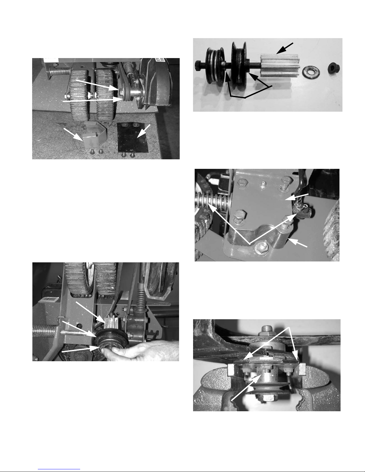
9. Remove and retain the Spindle Belt Guard and rubber
Debris Guard and their hardware. See Figure 1.
Spindle
Assembly
Blade within
Blade Guard
Spindle
Pulley
Debris
Spindle
Guard
Belt Guard
FIGURE 1
10. While an assistant holds down the Blade Control Bail
and slowly pulls the starter cord to rotate the spindle,
carefully work the belt off of the spindle pulley.
11. Rotate the blade so that both ends are within the
blade guard.
12. With a 9/16” box wrench and 9/16” socket and ratchet
remove and retain the two Pulleys and Pulley Mount
Spacer from the frame. Retain the washer and nut. See
Figure 2.
NOTE: There are several different pulley configurations
used during production.The photo represents only one of
these configurations.
Pulley Mount
Spacer
Taller shoulders
of the pulleys
must face towards
Pulley Mount Space
FIGURE 3
15. With a 1/2” box wrench and 1/2” socket and ratchet
remove and save the four (4) nuts and lock washers from
the bolts that hold the plastic Bearing Block/Spindle
Assembly to the frame. See Figure 4. Do not remove
bolts from Bearing Block and Spindle Assembly at
this time.
Index
Bracket
Blade Plate Assembly Rod
f the Spindle
Assembly
Bearing
Block
Pulley Mount
Spacer
“V” Idler
Spindle
Pulley
Belt
Debris
Guard
Guard
Flat Idler
Pulley
FIGURE 2
13. Remove and discard the original belt.
14. Refer to Figure 3. Remove the Pulley Mount Spacer
and both pulleys from the mounting bolt. Reassemble the
two pulleys and spacer as shown in Figure 3. Note the
position of the pulleys’ taller shoulders. Set the dual pulley stack assembly aside. It will be re-installed later.
FIGURE 4
16. Carefully remove the Bearing Block/Spindle Assembly
from the edger frame keeping the Bearing Block, Index
Bracket and the 4 bolts together.
17. Set the Bearing Block/Spindle Assembly in a vise as
shown in Figure 5. Note that the vise jaws are grabbing
the edge of the Blade Plate Assembly.
Blade Plate Assembly
Spindle
Assembly
FIGURE 5
18. Keeping the Bearing Block in position on the Blade
Plate Assembly Rod and releasing the tension on the
2
Page 3

Index Bracket from the Blade Adjustment Rod remove
the 4 bolts and Index Bracket. See Figure 6.
Blade Adjustment Rod
Blade Plate
Assembly Rod
Bearing
Block
FIGURE 6
19. Carefully remove the Bearing Block from the Blade
Plate Assembly Rod. CAUTION! The Bearing Block is
held in position by the Compression and Double Torsion
Springs.
20. Refer to Figure 7. Remove the cotter pin retaining the
Blade Adjustment Rod. Remove the Double Torsion
Spring from the Blade Plate Assembly Rod and Blade
Adjustment Rod. Discard the Blade Adjustment Rod.
NOTE: Observe how the Double Torsion Spring and
Blade Adjustment Rod interlock. You will need to
reassemble in the same manner later.
24. Re-install the flat washer onto the Blade Plate
Assembly Rod.
25. With the new Blade Adjustment Rod (Item 3) reassemble the Double Torsion Spring and new Blade
Adjustment Rod onto the Blade Plate Assembly Rod.
See Figure 8 for Double Torsion Spring orientation.
Blade Adjustment Rod
shown not fully through
Double Torsion Spring
for clarity
FIGURE 8
26. Re-install the cotter pin in the end of the Blade Control Rod.
27. Position the Bearing Block onto the Blade Plate
Assembly Rod as shown in Figure 9.
21. Remove the flat washer and gray colored Compression Spring from the Blade Plate Assembly Rod. Do not
remove the silver spacer from the rod. Discard the gray
colored Compression Spring.
Blade
Cotter Pin Removed
Adjustment
Rod
Washer
Double
Compression
Spring
Torsi on
Spring
FIGURE 7
22. This completes the disassembly of the edger.
Reassembly of Edger with New Parts:
23. Refer to Figure 7. Install the new Compression
Spring (gold colored) (Item 2) onto the Blade Plate
Assembly Rod.
FIGURE 9
28. Re-install the Index Bracket onto the Bearing Block
ensuring that the Blade Adjustment Rod is within the
Index Bracket cutout. Re-install the 4 bolts through the
Index Bracket and Bearing Block. See Figure 10.
3
Page 4

Smaller
Bottom
Pulley
FIGURE 10
29. Remove Bearing Block/Spindle Assembly from vise.
With a 1/2” box wrench and 1/2” socket and ratchet reinstall the Bearing Block/Spindle Assembly onto the
edger frame with the four (4) nuts and lock washers previously removed in Step 15. Tighten nuts securely.
30. Position the edger so that you can install the new “V”
Belt (Item 1) and reconfigured Pulley/Spacer Stack from
Step 14.
31. Install the new “V” Belt (Color Code- Orange) (Item 1)
by first installing the belt around the blade spindle pulley.
32. Keep the belt next to the Bearing Block as shown in
Figure 11.
Blade
Spindle
Pulley
FIGURE 12
36. The upper leg of the belt coming from the blade spindle pulley goes to the larger top idler pulley with the V of
the belt against the upper idler pulley. This also results in
a quarter turn twist in the belt between the spindle pulley
and the larger top idler pulley.
37. Keeping the belt correctly oriented against the top
and bottom idler pulleys dress the belt around the engine
pulley. To facilitate this final step of the belt installation
use a 9/16” open end wrench to rotate the engine pulley
as you work the belt around and on.
38. The belt leg coming off the larger top idler pulley goes
to the rear side of the engine pulley. See Figure 13.
NOTE: There should be no twist in either leg of the belt
between the engine pulley and idler pulleys.
Bearing Block
FIGURE 11
33. With a 9/16” box wrench and 9/16” socket and ratchet
re-install the the re-configured dual idler pulley stack from
Step 14. Ensure that both legs of the belt run along next
to the Bearing Block.
34. It is critical that the flat back of the belt goes against
the smaller bottom idler pulley and the V of the belt goes
against the larger top idler pulley.
35. The bottom leg of the belt coming from the bottom of
the blade spindle pulley goes to the smaller bottom pulley
with the back of the belt against the idler pulley. This will
result in a quarter turn twist in the belt between the spindle pulley and the smaller bottom idler pulley. See Figure
12.
Coming
off top
idler
pulley
Rear of Edger
FIGURE 13
39. Re-install the Debris Guard and Spindle Belt Guard
removed in Step 9. Securely tighten all hardware.
40. Remove the plastic sheet from under the fuel cap.
41. Pull the engine through with the starter cord the blade
should rotate in counterclockwise direction when looking
at the blade through the open (left) side of the blade
guard.
41. This completes the upgrade and reassembly of the
edger.
4
 Loading...