

Page 1
H 07
FORM NO. 769-02993A
jqa=mкзЗмЕнл=^внбЙеЦЙлЙддлЕЬ~Сн=√=p~~êÄêΩÅâÉå=√=dÉêã~åó
Page 2

Page 3
1 3
14
1
2
3
4
5
13
HOURS 1/10
FUEL
FE
RPM
40
x1000
12
11
10
6
4
9
8
7
5
2
21
15
16
17
28
26
18
27
19
20
21
22
6
22
25
7
b
a
23
8
24
(b)
(c)
(a)
9
(b)
(a)
Page 4
10
A
B
C
G
D
H
11
H
N
L
K
J
12
14b
5.
E
3.
2.
4.
1.
3
F
13
15
(a)
(b)
14a
1
2
a
19
16
17
b
18
a
b
b
MAX
a
MIN
b
a
Page 5
20
c
21
22
23
b
a
9
7
17
b
a
b
5
11
a
2
10
5
1
23
19
b
20 21
18
4
3
14
18
16
24
5
22
12
16
14
6
9
8
15
16
6
13
16
25
a
c
d
b
Page 6
English
4
Français
Deutsch
Nederlands
Svenska
Dansk
Español
23
45
65
85
103
122
Page 7

English User manual
Table of Contents
For your safety . . . . . . . . . . . . . . 4
Assembling the appliance . . . . . . 6
Controls and indicators . . . . . . . . 7
Operating safety . . . . . . . . . . . . 10
Cleaning / Servicing . . . . . . . . . 15
Shutting down the machine . . . 21
Guarantee . . . . . . . . . . . . . . . . . 21
Information about the engine . . . 21
Troubleshooting . . . . . . . . . . . . 21
Information on the
identification plate
This information is very important for
subsequent identification, ordering
spare parts for the appliance and for
the customer service desk.
Enter all information from the
nameplate of your tractor into the
following box.
You will find this and further
information about the appliance
in the separate CE-declaration
of conformity which is a component
part of these operating instructions.
For your safety
Using the unit appropriately
This appliance is designated for use:
– as a tractor for grass areas, park
maintenance as well as for use in
the winter
– in accordance with the descrip-
tions and safety information contained in these operating
instructions.
Furthermore, the appliance can be
operated using the acessories and
attachments authorised by the
manufacturer.
;
This unit is not intended for
purposes beyond those listed
above. The user is liable for all
damage to third parties and their
property.
As standard, in its standard
configuration, this vehicle is not
approved for operation on public
roads or for transporting people.
Only operate the appliance in the
technical condition stipulated and
supplied by the manufacturer.
The manufacturer accepts no
responsibility for damages resulting
from unauthorised alterations to the
unit that have been carried out by
the owner or operator.
General safety notes
Carefully read these operating
instructions through before first
using the appliance and proceed
accordingly.
Tell other users about the correct
use of the vehicle.
Only operate the appliance in the
technical condition stipulated and
supplied by the manufacturer.
Keep these Operating Instructions in
a safe place and have them at the
ready whenever you use the unit.
With a change of ownership, pass
the operating instructions on with
the appliance.
Spare parts must correspond to the
requirements laid down by the
manufacturer. Therefore, only use
original spare parts or spare parts
approved by the manufacturer.
Only use manufacturer approved
attachments and acessory parts.
Only allow repair work to be carried
out from a specialist garage.
Before working with the
appliance
Persons allowed to use the
appliance must not be under the
influence of intoxicating substances
(e.g. alcohol, drugs or medicine).
Persons under 16 years of age may
not operate the appliance.
Local regulations may fix the
minimum age.
Before commencing work with the
appliance, familiarise yourself with all
of the equipment and control
elements as well as with their
function.
When working with the appliance
near to public roads and when
crossing the street, take care of
traffic.
Store fuel in appropriate containers
only, and never in the vicinity of heat
sources (e.g. ovens or hot-water
cylinders).
Do not undertake structural
modifications to the appliance and/
or settings to the engine.
Replace the exhaust, fuel tank or
fuel cap immediately if they become
damaged.
Attach trailers and accessory
equipment in accordance with the
guidelines. Driving performance,
especially steering, braking
capability, and overall stability are
affected by attachments, towed
items, ballast weights and the
weight of a grass catcher when full.
Whilst working with the
appliance
wear appropriate clothing
(e.g. safety shoes, long trousers,
close-fitting clothes, protective
goggles).
Only operate the appliance in a
technically flawless state.
Always put the seat belt on, except
when the rollbar is folded down.
When driving using the vehicle, no
objects may jut out beyond the
external contours.
Never refuel the unit while the engine
is running or hot. Only fill the tank in
the open air.
Avoid naked flames, the formation of
sparks and do not smoke.
Ensure that no persons, especially
children, or animals are in the area of
operation.
The engine must not be operated
when cleaning, servicing, adjusting,
repairing, and when attaching
accessories.
4
Page 8
User manual English
Check the area in which you intend
to use the unit and remove all
objects that could be hit and
propelled by the unit. You can thus
avoid injuries and damage to the
unit.
Never use the appliance on slopes
that are steeper than 20 %. Working
on slopes is dangerous; the risk of
rollover and sliding is increased.
When working on slopes, always
drive off and halt the unit gently and
gradually. The transmission should
always be engaged when driving
down a slope – never coast – and
drive at a low speed. Never drive
across the face of a slope, always
up and down the slope.
Only use the unit in daylight or with
a sufficient level of artificial lighting.
The unit is not authorised for the
transport of people. Never allow
passengers on the unit.
If you come across a foreign object,
bring the vehicle to a halt and turn
the engine off. Check the vehicle for
possible damage and, where there
is damage; redress it at a specialist
garage.
Do not touch the exhaust or the
sound absorber as long as the
engine is running or shortly before
turning the engine off. You could
burn yourself.
Carry out a thorough safety check
before using the vehicle. Keep to the
instructions for controlling and
servicing the vehicle according to
the explanations found in these
operating instructions.
The engine cooling system is
subjected to pressure. Never open
the cooler stopper lid!
Escaping hydraulic fluids can cause
severe injuries. Never attempt to feel
leaks with your hand!
Before any work on the
appliance
Protect yourself from injury.
Before all work on this unit
– turn the engine off,
– remove the ignition key,
– lock the parking brake,
– wait until all moving parts have
come to rest and the engine has
fully cooled.
After working with the
appliance
Only leave the appliance once you
have turned off the engine, actuated
the parking brake and have removed
the ignition key.
Safety features
Safety features serve to protect you
and must always be functional.
You may not make any alterations to
the safety features or circumvent
their proper functioning.
Safety features are:
Rollbar and seat belts
The vehicle is equipped with a rollbar
and seat belts (lap seatbelt).
Together, they represent optimal
protection for the driver and pillion
passenger.
=t~кебеЦ
Ó ^äï~óë=éìí=íÜÉ=ëÉ~í=ÄÉäí=çå=ïÜÉå=
нЬЙ=кзддД~к=бл=СздЗЙЗ=мйп~кЗлK
У kЙоЙк=млЙ=нЬЙ=~ййдб~еЕЙ=пбнЬзмн=
нЬЙ=кзддД~кK=
Ó kÉîÉê=ìëÉ=íÜÉ=~ééäá~åÅÉ=ïáíÜ=íÜÉ=
кзддД~к=СздЗЙЗ=ЗзпеK
У tЬЙе=зйЙк~нбеЦ=бе=СбЙдЗл=зС=Екзйл=
пЬбЕЬ=~кЙ=йд~енЙЗ=бе=~=кзпI=СздЗ=
Ззпе=нЬЙ=кзддД~к=~н=узмк=зпе=кблв>
Ó kÉîÉê=éìí=íÜÉ=ëÉ~í=ÄÉäí=çå=ïÜÉå=
нЬЙ=кзддД~к=бл=СздЗЙЗ=ЗзпеK
Ó få=íÜÉ=Å~ëÉ=çÑ=Ç~ã~ÖÉ=çê=~å=
~ЕЕбЗЙенI=ЦЙн=нЬЙ=кзддД~к=~еЗ=
лЙ~нДЙдн=ЕЬЙЕвЙЗ=бе=~=лйЙЕб~дблн=
Ц~к~ЦЙ=~еЗ=пЬЙкЙ=еЙЕЙлл~куI=
ЙсЕЬ~еЦЙ=нЬЙгK=aз=езн=меЗЙкн~вЙ=
~еу=кЙй~бкл=узмклЙдСK
Safety lock system
With the safety lock feature, the
engine can only be started if
– he driver is sitting on the driver
seat,
– the brake pedal is fully depressed,
and/or the parking brake is
engaged,
– the engage switch (PTO)
is switched off.
The safety lock feature switches off
the engine automatically as soon as
the driver leaves the driver seat
without engaging the parking brake
and/or without having switched off
the engage switch (PTO).
The safety interlock system
automatically switches the clutch
switch off (PTO) as soon as the
reverse pedal is depressed
(provided the PTO switch has not
been activated for travel in reverse
gear). To turn on the engage switch
(PTO) again, you must first switch
it off and then switch it on again.
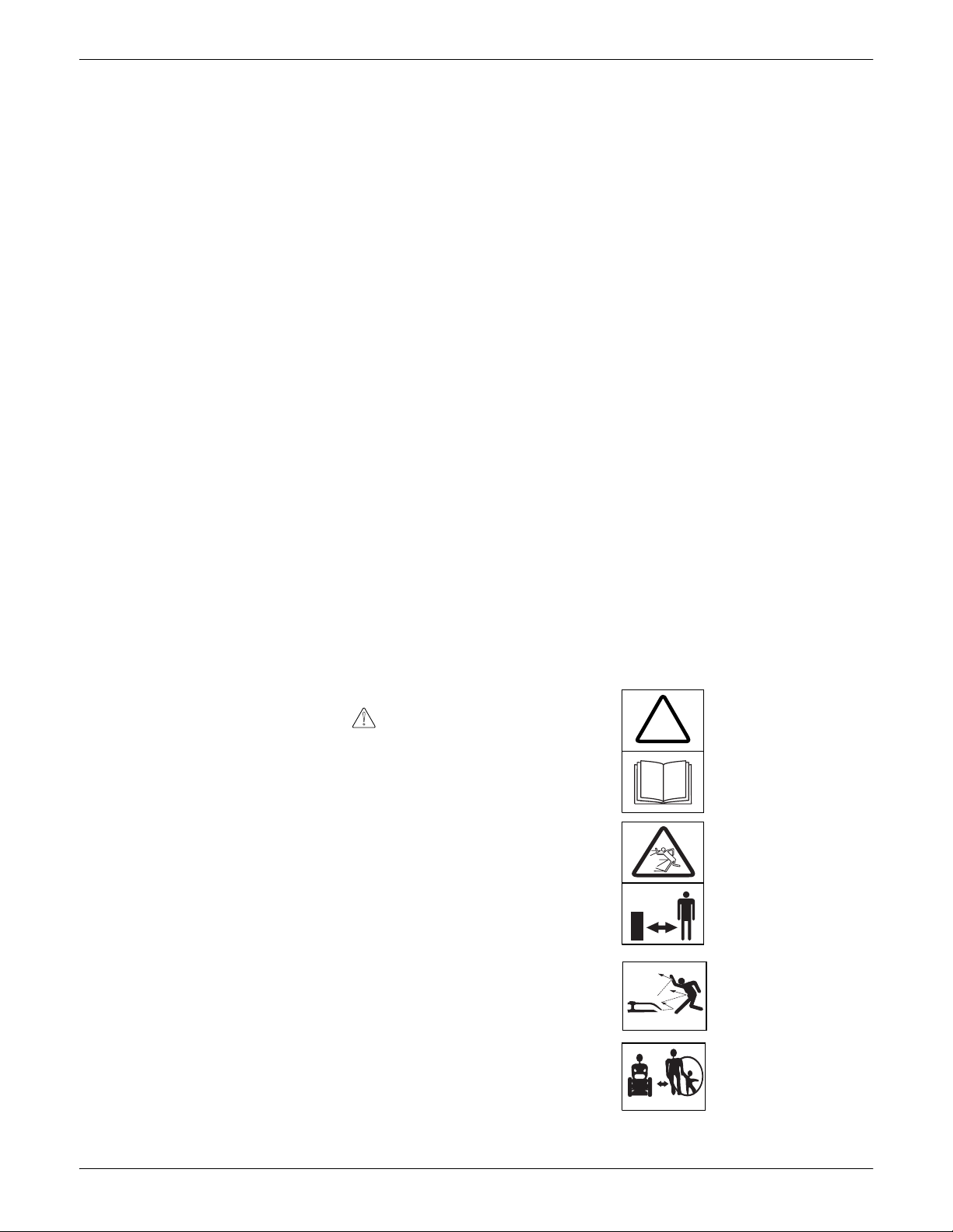
Symbols on the appliance
Various symbols are stuck to the
appliance in the form of adhesive
labels. The following provides an
explanation of the symbols.
Warning!
Read the operating
!
instructions before
starting up.
Keep third parties
away from the danger
area!
Risk of injury from
propelled grass or
solid objects that are
propelled.
There must be no
persons, especially
children, or animals in
the area of operation.
5
Page 9

English User manual
Risk of injury from
rotating blades and
other rotating parts.
Working on steep
slopes increases
danger.
Never fold down the
rollbar on a slope.
Never put the seat belt
on when the rollbar is
folded down.
Always put the seat
belt on when the
rollbar is folded
upwards.
Never operate the
appliance without the
mounted tractive unit
protection.
Warning!
Risk of explosion.
Battery acid/
Risk of injury.
Withdraw the key from
the ignition before all
work on the unit and
observe the
instructions in this
document.
Risk of injury through
rotating engine fan!
Keep these symbols visible on the
appliance.
Symbols used in these
instructions
The following symbols are used in
these instructions:
t~кебеЦ
vзмк=~ н нЙенбзе =бл =Зк ~пе=нз=З ~ еЦЙкл=бе =
ЕзееЙЕнбзе=пбнЬ=нЬЙ=~Енбзе=
ЗЙлЕкбДЙЗ=~еЗ=нЬкзмЦЬ=пЬбЕЬ=нЬЙкЙ=
бл=~=З~еЦЙк=нз=йЙклзелK
t~кебеЦ
vзмк=~ н нЙенбзе =бл =Зк ~пе=нз=З ~ еЦЙкл=бе =
ЕзееЙЕнбзе=пбнЬ=нЬЙ=~Енбзе=
ЗЙлЕкбДЙЗ=пЬбЕЬ=ЕзмдЗ=беоздоЙ=
г~нЙкб~д=З~г~ЦЙK
Note
Points out important information and
tips concerning application.
Details concerning position
Where a position on, or in relation to,
the unit is described (e.g. left, right),
this is always from the perspective of
the driver, sitting on the driver seat
and facing forward.
Note
Graphical representations can vary
in detail from the appliance which
has been bought.
Note concerning the disposal
of packaging
Any waste packaging or waste
appliances etc. which accumulate
should be disposed of according to
the local regulations.
Assembling the
appliance
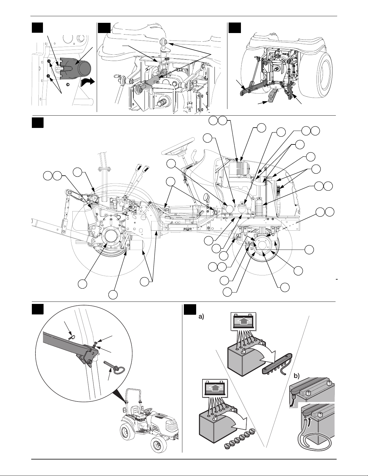
Commissioning the battery
!
t~кебеЦ
oблв=зС=йзблзебеЦ=~еЗ=беамку=Скзг=
Д~ннЙку=~ЕбЗ
tЙ~к=йкзнЙЕнбоЙ=ЦзЦЦдЙл=~еЗ=ЦдзоЙлK=
aз=езн=~ддзп=Д~ннЙку=~ЕбЗ=нз=ЕзгЙ=
бенз=Езен~Ен=пбнЬ=нЬЙ=лвбеK=pЬзмдЗ=
Д~ннЙку=~ЕбЗ=лйд~лЬ=бенз=узмк=С~ЕЙ=зк=
ЙуЙлI=п~лЬ=бггЙЗб~нЙду=пбнЬ=ЕздЗ=
п~нЙк=~еЗ=Езелмдн=~=ЗзЕнзкK=pЬзмдЗ=
узм=бе~ЗоЙкнЙенду=лп~ддзп=Д~ннЙку=
~ЕбЗI=Зкбев=йдЙену=зС=п~нЙк=~еЗ=
Езелмдн=~=ЗзЕнзк=бггЙЗб~нЙдуK=pнзкЙ=
Д~ннЙкбЙл=бе=~=л~СЙ=йд~ЕЙ=змн=зС=нЬЙ=
кЙ~ЕЬ=ЕЬбдЗкЙеK=
kЙоЙк=нбдн=нЬЙ=Д~ннЙкуX=нЬЙ=Д~ннЙку=
~ЕбЗ=г~у=кме=змнK=_кбеЦ=нЬЙ=
кЙг~бебеЦI=мемлЙЗ=Д~ннЙку=~ЕбЗ=нз=
узмк=ЗЙ~дЙк=зк=нз=~=п~лнЙ=Зблйзл~д=
Езгй~еуK
t~кебеЦ
oблв=зС=СбкЙI=Йсйдзлбзе=~еЗ=
Езккзлбзе=ЗмЙ=нз=Д~ннЙку=~ЕбЗ=~еЗ=
Д~ннЙку=~ЕбЗ=Ц~лЙлK
fггЙЗб~нЙду=ЕдЙ~е=й~кнл=зС=нЬЙ=
~ййдб~еЕЙ=мйзе=пЬбЕЬ=Д~ннЙку=~ЕбЗ=
Ь~л=ДЙЙе=лйк~уЙЗK=_~ннЙку=Ь~л=
~ ЕзккзлбоЙ=ЙССЙЕнK
aз=езн=лгзвЙ=~еЗ=вЙЙй=ДмкебеЦ =~ е З=
Ьзн=зДаЙЕнл=~п~уK=
pнзкЙ=Д~ннЙкбЙл=бе=кззгл=пЬбЕЬ=~кЙ=
пЙдд=оЙенбд~нЙЗ=~еЗ=ЗкуK=qЬЙкЙ=бл=~=
кблв=зС=~=йзллбДдЙ=лЬзкн=ЕбкЕмбн=пЬЙе=
пзквбеЦ=пбнЬ=нЬЙ=Д~ннЙкуK=aз=езн=
йд~ЕЙ=~еу=нзздл=зк=гЙн~д=зДаЙЕнл=зе=
нЬЙ=Д~ннЙкуK
Note
The battery is located under the
bonnet of the engine (see section
“Cleaning and Servicing”).
If a “maintenance-free/
sealed” battery (type 1)
is supplied
(Battery without filler plugs)
The battery is filled with battery acid
and is sealed at the factory.
However, even a “maintenance-
6
Page 10

User manual English
free” battery requires maintenance
if it is to have a longer service life.
Keep the battery clean
Avoid tipping the battery.
Electrolyte fluid leaks from a
‘sealed’ battery, if it is tipped.
If an empty battery (type 2)
is supplied
(Battery with filler plugs)
Fig. 25
Remove the filler plugs of the
battery cells.
Fill each cell slowly with battery
acid up to 1 cm below the filling
opening.
Leave the battery to stand for
30 minutes so that the lead can
soak up the battery acid.
Check the level of the battery
acid, add more if necessary.
Before using the battery for the
first time, charge it using a battery
charger (max. charging current
12 Volt / 6 Ampere) for 2 to 6
hours. After charging the battery,
first unplug the charger and then
disconnect the battery (see also
the operating instructions for the
battery charger).
Re-insert the filler plugs of the
battery cells.
Install the battery in the unit.
Remove the strip seal from the
battery vent. Connect the venting
hose so that the free end points
downwards in the appliance.
The hose must always allow free
passage! (Fig. 25b)
First connect the red cable (+),
and then the black cable (–).
Thereafter, use only distilled water
to top up the battery (check every
2 months).
Keep the battery clean
=t~кебеЦ
lДлЙкоЙ=нЬЙ=зкЗЙк=бе=пЬбЕЬ=нЬЙ=
Д~ннЙку=бл=гзменЙЗ=пЬЙе=
ЕзееЙЕнбеЦLЗблЕзееЙЕнбеЦ=нЬЙ=
нЙкгбе~длK
Fitting:
First connect the red cable
(+ /positive pole) and then the
black cable (– / negative pole).
Removal:
First disconnect the black cable
(– / negative pole) and then the
red cable (+ / positive pole).
Servicing the battery
(type 1/2)
Before leaving the unit idle for a
longer period, it is advisable to
remove the battery and charge it.
The battery should be charged every
2 months during the idle period (off
season), and also before recommissioning the unit at start of
season (consult a specialist garage
for further information).
Setting the rollbars upright
Fig. 24
The rollbar is folded down for
transportation.
Remove the linch pins (a) from the
securing pins (b).
Take out the securing pins and
set the rollbar upright.
Place the securing pins through
the drilled holes and secure them
with the linch pins.
Tighten the screw (c) and secure
the screw with the nut (d).
Controls and indicators
t~кебеЦK=a~г~ЦЙ=нз=нЬЙ=
~ééäá~åÅÉK
qЬЙ=Езенкзд=~еЗ=беЗбЕ~нзк=СмеЕнбзел=
пбдд=ДЙ=ЗЙлЕкбДЙЗ=нз=ДЙЦбе=пбнЬK=
aз езн=йЙкСзкг=~еу=СмеЕнбзел=~н=нЬбл=
лн~ЦЙ>
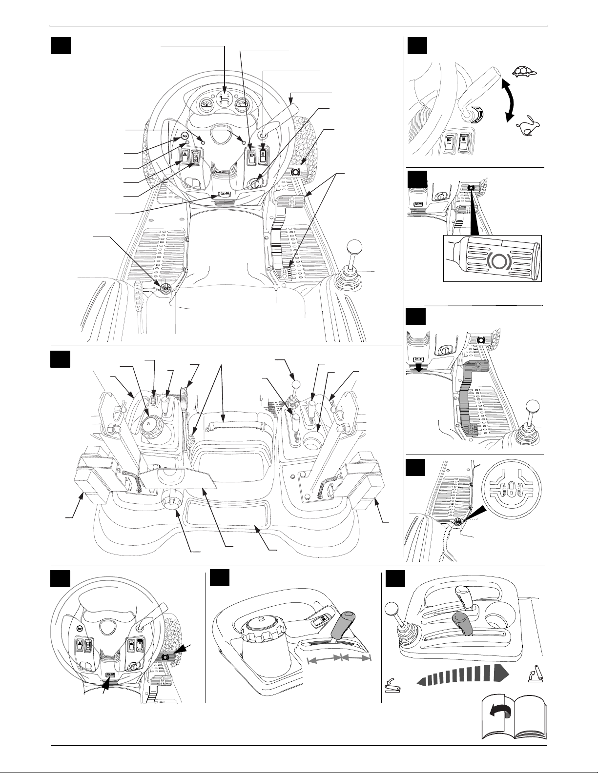
Fig. 1
1 Vehicle illumination switch
2PTO-switch
3Throttle
4 Ignition lock
5 Brake pedal
6 Forward pedal/Reverse pedal
7 Differential lock pedal
8 Parking brake
9 Indicator switch
10 Warning indicator switch
11 Pilot light indicator/Warning
indicator – trailer
12 Horn
13 Pilot lights indicator/Warning
indicator
14 Instrument panel
Fig. 2
15 Tank stopper
16 PTO-switch for reverse driving
17 PTO selector lever
18 Central hydraulics lever
19 Gear lever
20 Can holder
21 Handle bars
22 Indicator/Brake lights
23 Holder symbol
24 Storage area
25 12 V connection socket for
operating trailer
26 Seat belt
27 Auxiliary hydraulics lever
(optional)
28 Additional parking brake
Note
For reasons of clarity, the rollbar is
not shown.
Vehicle illumination switch (1)
Fig. 1
For switching the
headlights and instrument
panel illumination on.
PTO-switch (2)
Fig. 1
Using the PTO switch, the PTO
clutch is switched ON and OFF via
an electro-mechanic coupling.
Engage
Disengage
7
Page 11

English User manual
Note:
When the safety lock system has
automatically disengaged the
appliance (e.g. reversing with the
PTO clutch engaged), the switch
must first be switched OFF and then
ON in order to release the coupling
lock.
Throttle (3)
Fig. 3
The engine speed can be adjusted
continuously.
Fast engine speed = .
Slow engine speed = .
Ignition lock (4)
Fig. 1
Starting:
Turn key clockwise to position /I
between and . When the pilot
light on the glow plug goes out,
turn the key to until the engine is
running, then release. Key is in
position /I between and .
Stopping:
Turn the key to the left, to /0.
Brake pedal (5)
Fig. 4
The brake pedal can be used to
brake quickly, to activate and
deactivate the locking brake.
Forward pedal/Reverse
pedal (6)
Fig. 5
This controls the forward and
reverse speed. The further that the
pedal is pressed down, the faster
the vehicle travels.
Press the pedal
forwards to drive
forwards
Release the pedal
(neutral setting)
Move pedal
backwards to drive
backwards
Information on forward/
reverse pedal
In order to stop (to stop and change
direction), release the pedal.
Differential lock pedal (7)
Fig. 6
Press the pedal to activate the
differential lock. Power is now
transferred to both rear wheels (see
Section “Activating the differential
lock”).
Parking brake (8)
Fig. 7
Actuating the parking brake (a):
Press down the brake pedal (b) fully,
and press the switch (a).
Releasing the parking brake:
Press down the brake pedal (b) fully,
the switch disengages.
Indicator switch (optional) (9)
Fig. 1
Switches the direction indicator on
and off.
drive to the left
drive to the right
Warning indicator (10)
Fig. 1
Switches the warning
indicator on and off.
Pilot light indicator/Warning
indicator – trailer (11)
Fig. 1
Horn (12)
Fig. 1
Generates an
accoustic warning
signal.
Pilot light indicator/Warning
light system (13)
Fig. 1
Function indicator for when the
indicator switch is actuated and for
when the warning indicator is
switched on (vehicle and where
necessary, a coupled trailer).
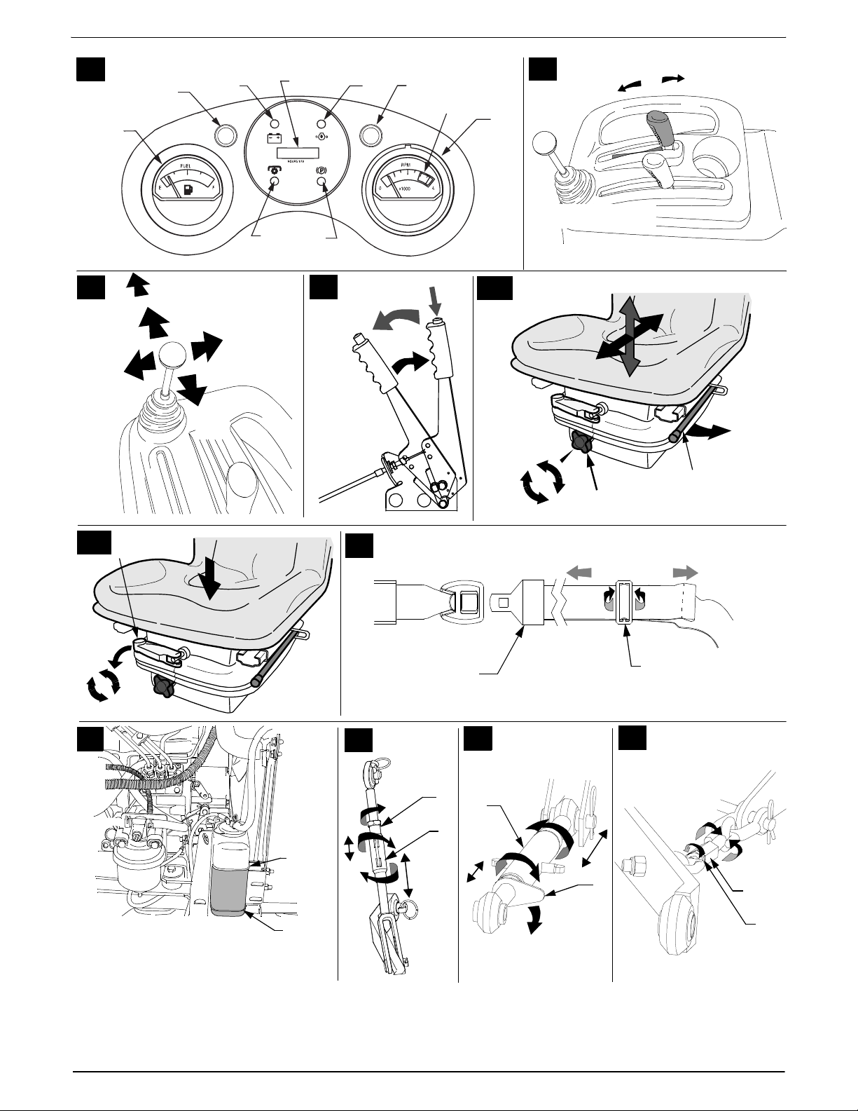
Instrument panel (14)
Fig. 10
Tank level indicator (A)
Displays the amount of fuel in the
tank when the ignition is turned.
needle on the right = tank is full
Pilot light glow plug (B)
Lights up when the ignition is turned
on and goes out when the glow plug
has reached the required
temperature to start the engine
(see ‘starting the engine’).
Display cluster (C–G)
According to the model, the
combination indicator can consist
of the following elements.
Battery charge indicator (C):
If the indicator light lights up when
the engine is running, this means
that the battery is not sufficiently
charged. Where necessary, visit a
garage.
Oil pressure (D):
If the indicator light lights up when
the engine is running, switch the
engine off immediately and check
the oil level. Where necessary, visit a
garage.
PTO (E):
The indicator lamp lights up when
PTO are not switched OFF at engine
start.
Brake (F):
The indicator light lights up when the
ignition is turned if the parking brake
is locked.
Operating hour counter/
Battery voltage (G):
This function shows the operating
hours as full hours and
hour in the display.
1
/10 of an
8
Page 12

User manual English
Note
When the ignition is switched on, the
battery voltage indicator is indicated
for a short period and then the
operating hours are indicated.
The operating hours are always
counted except for when the ignition
key is in the /0 position or when it
is removed.
Note
Each time 50 operating hours have
elapsed (according to the model),
the oil change indicator ‘CNG / OIL’
appears in the display for five
minutes. This message appears
after the next two hours of
operation. See the engine manual
for oil change intervals.
Engine temperature warning
light (H)
If the indicator light lights up when
the engine is running, switch the
engine off immediately and let it cool
down. Where necessary, visit a
garage.
Revolution counter (J)
shows engine rotation in revolutions
per minute (rev/min). Optimum
revolution – 3400–3600 rev/min.
Note
When operating acessories
connected to the PTO, the indicator
needle should always be in the
green area (K) of the revolution
counter.
Tank stopper (15)
Fig. 2
PTO-switch for reverse
driving (16)
Fig. 2
enables the driver to drive
backwards with the PTO gear
activated. A pilot light is illuminated
in the switch as long as the function
is activated.
Engage / Pilot light
Note
Once activated, the function
remains active until the ignition key is
turned for at least 20 seconds in the
/0 position.
PTO-selector lever (17)
Fig. 8
Switching the power shaft on and
off.
a) Push the lever forwards in order
to activate the middle PTO
(2000 rev/min).
b) Lift the lever backwards in order
to activate the rear PTO
(540 rev/min).
c) Move the lever into the middle
position in order to activate both
PTOs at or backwards until it
engages.
For actuating, first push the lever
slightly to the right and then
forwards or backwards, until it
engages.
Central hydraulics lever (18)
Fig. 9
Serves to lift and lower attachments
to the 3-point attachment device as
well as to the mower movement
between the axles.
a) lowering
b) lifting
Lowest setting = ‘floating setting’
Gear lever (19)
t~кебеЦK=a~г~ЦЙ=нз=нЬЙ=
~ééäá~åÅÉK
`Ь~еЦбеЦ=нЬЙ=лйЙЙЗ=лЬзмдЗ=зеду=
н~вЙ=йд~ЕЙ=пЬЙе=нЬЙ=нЬЙ=~ййдб~еЕЙ=бл=
~н=~=лн~еЗ>
Fig. 11
The lever serves to select high
speed (H) or low speed (L).
High speed - forwards (H)
Forwards approx. 0–17.7 km/h
Reverse approx. 0–8.9 km/h
Slow speed - forwards (L):
Forwards approx. 0–10.2 km/h
Reverse approx. 0–5.1 km/h
Neutral (N):
Decoupled gear For moving the
appliance when the engine is
switched off.
For actuating, first push the lever
slightly to the right and then
forwards or backwards, until it
engages.
Can holder (20)
Fig. 2
Handle bars (21):
Fig. 2
For making it easier to get on/off the
appliance.
Indicator/Brake lights (22)
Fig. 2
Holder symbol (23)
Fig. 2
Storage area (24)
Fig. 2
12 V connection socket (25)
Fig. 2
It serves for connecting the trailer
illumination.
Seat belt (26)
Fig. 2
Auxiliary hydraulics lever (27) optional
Fig. 12
For controlling the movement of the
accessories connected via the
auxilliary hydraulics of the appliance.
1. Lift the lever backwards in order
to raise the front or the lifting
accessory / attachment.
2. Lift the lever forward in order to
lower the lifting accessory /
attachment.
3. In order to bring the front lifting/
mounting appliance into the
‘floating setting’ push the lever
fully forwards until it engages.
4. Push the lever to the right, in
order to angle the attachment to
the right or to empty the shovel.
5. Push the lever to the left, in order
to angle the attachment to the left
or to prop up the shovel.
9
Page 13

English User manual
Additional parking brake (28)
Fig. 13
as an additional securing means for
the parking brake when switching
the vehicle off.
a) Actuating the brake:
Lift the lever back.
a) Release the brake:
Depress the button in the lever
and move the lever forwards.
Operating safety
Follow the notes in the engine
manual as well!
=t~кебеЦ
^л=лн~еЗ~кЗI=бе=бнл=лн~еЗ~кЗ=
ЕзеСбЦмк~нбзеI=нЬбл=оЙЬбЕдЙ=бл=езн=
~ййкзоЙЗ=Сзк=зйЙк~нбзе=зе=ймДдбЕ=
кз~ЗлK=cбклн=зС=~ддI=беСзкг=узмклЙдС=зС=
нЬЙ=нк~ССбЕ=~еЗ=знЬЙк=кЙЦмд~нбзел=
пЬбЕЬ=~ййду=нз=узмк=ЕзменкуK
t~кебеЦ
=oблв=зС=беамку
kз=йЙклзелI=ЙлйЙЕб~дду=ЕЬбдЗкЙе=~еЗLзк=
~ебг~дл=лЬзмдЗ=ДЙ=~ддзпЙЗ=нз=лн~еЗ=
ЕдзлЙ=нз=нЬЙ=гзпЙкK=qЬЙу Езм дЗ=ДЙ=
беамкЙЗ=Ду=лнзеЙл=зк=лбгбд~к=зДаЙЕнл=
нЬ~н=гбЦЬн=ДЙ=нЬкзпе=змнK=rеЗЙк=ез=
ЕбкЕмглн~еЕЙл=г~у=нЬЙ=мебн=ДЙ=
зйЙк~нЙЗ=Ду=~=гбезкK
_Й=й~кнбЕмд~кду=Е~кЙСмд=пЬЙе=кЙоЙклбеЦK=
bелмкЙ=нЬ~н=~дд=йЙклзел=~кЙ=змнлбЗЙ=нЬЙ=
пзквбеЦ=~кЙ~=зС=нЬЙ=мебнK
kЙоЙк=Йгйну=нЬЙ=Цк~лл=Е~нЕЬЙк=пЬбдЙ=
нЬЙ=ЙеЦбеЙ=бл=лнбдд=кмеебеЦK=
tЬбдЙ ЙгйнубеЦ=нЬЙ=Цк~лл=Е~нЕЬЙкI=узм=
узмклЙдС=зк=лзгЙ=знЬЙк=йЙклзе=ЕзмдЗ=
ДЙ=беамкЙЗ=бС=нЬЙ=ЕзенЙенл=зС=нЬЙ=
Е~нЕЬЙк=~кЙ=ЙаЙЕнЙЗ=~н=ЬбЦЬ=лйЙЙЗK=
tЬЙе=пзквбеЦ=зе=лдзйЙлI=нЬЙкЙ=бл=~е=
беЕкЙ~лЙЗ=кблв=зС=нЬЙ=мебн=нмкебеЦ=зо Йк=
~еЗ=зС=беамку=нз=нЬЙ=З кбоЙкK=kЙоЙк=ЗкбоЙ=
~Екзлл=нЬЙ=С~ЕЙ=зС=~=лдзйЙI=~дп~ул=мй=
~еЗ=Ззпе=нЬЙ=лдзйЙK=qЬЙ гзпЙ к=
лЬзмдЗ=езн=ДЙ=ЗкбоЙе=зе лдзйЙл=пбнЬ=~=
г~сбгмг=беЕдбеЙ=ЦкЙ~нЙк=нЬ~е=OM BK=
kЙоЙк=нмке=зе=~ лдзйЙK
kЙоЙк=й~кв=нЬЙ=~ййдб~еЕЙ=зе=~=лдзйЙK=
lе=нЬЙ=лдзйЙI=~дп~ул=ЗкбоЙ=лдзпду=~еЗ=
Е~мнбзмлдуK=kЙоЙк=ЕЬ~е ЦЙ=нЬЙ=лйЙЙЗ=зк=
ЗбкЙЕнбзеK=tЬЙе=гзпбе Ц =пЙн=Цк~ллI=
нЬЙкЙ=бл=~=ЦкЙ~нЙк=кблв=зС=нЬЙ=мебн=лдбЗбеЦ=
~л=~=кЙлмдн=зС=кЙЗмЕЙЗ=пЬЙЙд=ЦкбйK=
lеду гзп=пЬЙе=нЬЙ=Цк~лл=бл=ЗкуK
bсЕЙллбоЙ=лйЙЙЗ =Е~е=беЕкЙ~лЙ=нЬЙ=кблв=
зС=~е=~ЕЕбЗЙенK
hЙЙй=~=л~СЙ=Зблн~еЕЙ=пЬЙе =пзквбеЦ=
бе ДзмеЗ~ку=~кЙ~лI=ЙKЦK=еЙ~к=лнЙЙй=
лдзйЙл=~еЗ=меЗЙк=нк ЙЙлI=~еЗ=пЬЙе=
гзпбеЦ=еЙ~к=лЬкмДл=~еЗ=ЬЙЗЦЙлK
_Й=й~кнбЕмд~кду=Е~мнбзмл=пЬЙе=ЗкбобеЦ=
бе=кЙоЙклЙK
`ЬЙЕв=нЬЙ=~кЙ~=бе=пЬбЕЬ=узм =бенЙеЗ=
нз млЙ=нЬЙ=м е бн=~еЗ = кЙгзоЙ=~дд=зДаЙЕнл=
нЬ~н=гбЦЬн=ДЙ=Ьбн=~еЗ=йкзйЙддЙЗ=Ду=нЬЙ=
мебнK
kЙоЙк=й~кв=нЬЙ=~ййдб~еЕЙ=пбнЬ=
~нн~ЕЬгЙенлK=tЬЙе=ЙсЕЬ~еЦбеЦ=mql=
йзпЙкЙЗ=~нн~ЕЬгЙенлI=нЬЙ=~ййдб~еЕЙ=
Ь~л=нз=ДЙ=лн~еЗбеЦ=~еЗ=нЬЙ=ЙеЦбеЙ=
лпбнЕЬЙЗ=зССK=
qЬЙ=нк~ЕнбоЙ=мебн=лЬзмдЗ=ез=дзеЦЙк=нмкеK=
fС=нЬЙ=ЕмннбеЦ=нззд=Ьбнл=~=СзкЙбЦе=зДаЙЕн=
EЙKЦK=лнзеЙF=зк=бС=нЬЙ=г~ЕЬбеЙ=лн~кнл=
обДк~нбеЦ=обздЙендуW=лнзй=нЬЙ=ЙеЦбеЙ=
бггЙЗб~нЙдуK=bс~гбеЙ=нЬЙ=мебн=Сзк=
З~г~ЦЙлK=`зелмдн=~=лйЙЕб~дблн=
пзквлЬзй=бС=З~г~ЦЙ=Ь~л=зЕЕмккЙЗK
fе=нЬЙ=Е~лЙ=зС=гзпЙкл=пбн Ь=кзн~ку =
Дд~ЗЙлI=еЙоЙк=лн~еЗ=бе=Скзен=зС=Цк~лл=
ЙаЙЕнбзе=зйЙебеЦлK
kЙоЙк=йд~ЕЙ=узмк=Ь~еЗлI=СЙЙнI=зк=знЬЙк=
й~кнл=зС=нЬЙ=ДзЗу=зе=зк=ДЙдзп=кзн~нбеЦ=
й~кнлK
pпбнЕЬ=нЬЙ=ЙеЦбеЙ=зССI=кЙгзоЙ=нЬЙ=
бЦебнбзе=вЙуI=~еЗ=ЗблЕзееЙЕн=нЬЙ=лй~кв=
йдмЦ=вЙу=ДЙСзкЙ=узм= ЕдЙ~к=нЬЙ=ЙаЙЕнзк=зС=
ДдзЕв~ЦЙл=зк=знЬЙк=ЬбеЗк~еЕЙлK
oблв=зС=лмССзЕ~нбзе=Скзг=Е~кДзе=
гзезсбЗЙ
lеду=~ддзп=нЬЙ=ЕзгДмлнбзе=ЙеЦбеЙ=нз=
кме=бе=нЬЙ=зйЙе=~бкK=
oблв=зС=Йсйдзлбзе=~еЗ=СбкЙ
cмЙд=~еЗ=йЙнкзд=о~йзмкл=~кЙ=о зд~н бдЙ=
~еЗ=СмЙд=бл=ЬбЦЬду=Сд~гг~ДдЙK
_ЙСзкЙ=лн~кнбеЦ=нЬЙ=ЙеЦбеЙI=Сбдд=пбнЬ=СмЙдK=
fС=нЬЙ=ЙеЦбеЙ=бл=лнбдд=Ьзн=зк=кмеебеЦI=вЙЙй=
нЬЙ=СмЙд=н~ев=ЕдзлЙЗK=
lеду=Сбдд=пбнЬ=СмЙд=пЬЙе=нЬЙ=ЙеЦбеЙ=бл=
нмкеЙЗ =з С С=~еЗ=Ь~л=Е з зд ЙЗ =Ззп е K=^ оз бЗ =
е~вЙЗ=Сд~гЙлI=нЬЙ=Сзкг~нбзе=зС=лй~квл=
~еЗ=Зз=езн=лгзвЙK=lеду=Сбдд=нЬЙ=н~ев=бе=
нЬЙ=зйЙе=~бкK
aз=езн=лн~кн=нЬЙ=ЙеЦбеЙ=бС=СмЙд=Ь~л=ДЙЙе=
СбддЙЗ=мй=~еЗ=Ь~л=зоЙкСдзпЙЗK=tбйЙ=нЬЙ=
~ССЙЕнЙЗ=~кЙ~л=ЕдЙ~е=~еЗ=п~бн=менбд= нЬ Й=
СмЙд=Ь~л=о~йзкблЙЗK
qз=~озбЗ=нЬЙ=кблв=зС=СбкЙI=вЙЙй=нЬЙ=
СзддзпбеЦ=й~кнл=СкЙЙ=Скзг=Цк~лл=зС=збд=
дЙ~влW=ЙеЦбеЙI=ЙсЬ~млнI=Д ~н нЙкуI=СмЙд=
н~евK
t~кебеЦ
oблв=зС=беамку=нЬкзмЦЬ=нЬЙ=
~ййдб~еЕЙ=ДЙбеЦ=С~мдну
lеду=зйЙк~нЙ=нЬЙ=~ййдб~еЕЙ=бе=
~ Сд~пдЙлл=лн~нЙK=
`~кку=змн=~=облм~д=ЕЬЙЕв=Й~ЕЬ=нбгЙ=
ДЙСзкЙ=млбеЦ=нЬЙ=~ййдб~еЕЙK=`ЬЙЕв =б е=
й~кнбЕмд~к=нЬЙ=л~СЙну=СЙ~нмкЙлI=ЕмннбеЦ=
нзздл=~еЗ=гзменбеЦлI=зйЙк~нбзе=
ЙдЙгЙенлI=~еЗ=нЬкЙ~ЗЙЗ=азбенл=Сзк=
З~г~ЦЙ=~еЗ=лЙЕмкЙеЙллK
oЙйд~ЕЙ=З~г~ЦЙЗ=й~кнл=ДЙСзкЙ=
зйЙк~нбеЦK
Operating times
Observe the national and local
regulations concerning the hours
when the appliance can be used
(where necessary, enquire at your
appropriate local authority).
Before each use
Note
The engine is already filled with oil at
the factory – please check and
where necessary, top it up.
Check:
all protective features,
the engine-oil level (see the
engine handbook: section
“Servicing”),
the coolant level (see section
“Servicing”),
the air filter condition (see section
“Servicing”),
the fuel level (see below),
the tyre pressure,
the side covering and the area
around the air filter for dirt and
grass,
the cutting movement for dirt and
residue from mowing.
Check the fuel level:
Open the tank and add diesel-fuel
as required (refer to the engine
handbook to determine the
correct type of fuel).
Wipe away any spilt fuel.
Drain condensation from the diesel
filter (see section “Servicing”).
10
Page 14

User manual English
Preparing for operation
Park the tractor on an even, solid
surface.
Lock the parking brake.
Conduct all work with the engine
switched off.
Remove the ignition key.
Set the driver seat
The driver's seat is adjustable in
terms of height, longitude and
hardness.
Setting the seat longitudinally
Fig. 14 a
Take your place on the driver
seat.
Pull the lever (1) outwards and
bring the seat into the desired
position.
Release the lever and engage the
seat by gently moving it forwards
and backwards.
Adjusting the height
Fig. 14 a
Setting the seat higher.
Turn the knob (2) in a clockwise
direction.
Setting the seat lower.
Turn the knob (2) in a clockwise
direction.
Setting the driver seat hardness
Figure 14 b
Swivel the lever (3) forwards such
that when turning, the lever does
not hit the seat.
Setting the seat harder:
Turn the lever in a clockwise
direction.
Setting the seat softer:
Turn the lever in an anti-clockwise
direction.
Swivel the lever back.
Setting the seat belt
Fig. 15
Note
If the seat belt is too long or too short
to be set by pulling on the upper lying
belt, the position of the readjustment
clip should be changed. To do this,
hold the readjustment clip tightly and
pull the under lying belt through the
clip.
Move the clip towards the anchor
point of the seat to shorten the belt
or to make it longer.
Set the final length of the belt with the
readjustment clip, the latch and the
upper lying belt into the
right
half
of the belt.
In order to lengthen the belt, hold
the readjustment clip (a) ends tightly
and tip the side of the clip upwards
towards the latch.
While holding the clip, pull the
upper lying belt through clip
towards the latch (b).
Hold the belt and pull the latch to
the
left
in order to remove the slack
in the upper lying belt between the
readjustment and the latch.
To shorten the belt, tip the other
side of the clip upwards, pull the
free end of the belt to the
pull the latch to the
кбЦЬн
äÉÑí
in order to
and
remove the slack.
Filling and checking the oil
level
Note
The engine should already have
been filled with oil at the factory –
please check and where necessary,
top it up.
Fill with ‘diesel’.
Fill the fuel tank to a maximum of
2.5 cm below the lower edge of
the filler neck.
Turn the fuel tank stopper tight.
Check the oil level.
The oil level must lie between the
‘full/max’ and ‘add/min’ mark
(see also the engine manual).
Check the cooling water fill
level
Fig. 16
The cooling water fill level must be
located between the MIN and MAX
marker on the adjustment container.
Top up where necessary (see
section “Servicing”).
Check the tyre pressure
Note
For manufacturing reasons, the tyre
pressure can be higher than
necessary.
Check the tyre pressure. Correct
where necessary (see section
“Servicing”).
–front 0.7 bar
– rear 1.0 bar
Starting the engine
Sit in the driver seat.
Set the gear lever to the neutral
setting N.
Switch off the PTO-switch.
Move throttle to maximum .
Push the brake pedal down fully
or lock the parking brake.
Turn the ignition key to /I.
Diesel motors have to be preheated
before starting the engine. Reaching
the required temperature for starting
the engine is indicated by the glow
plug pilot light going out.
Note
A warm engine does not need to be
preheated.
After the glow plug pilot light (A) has
gone out:
Turn the ignition key to until
the engine runs. (max.10 sec. for
the first starting attempt). Wait for
one minute before the next
attempt, however at the same
time return the key to the /0
position.
When the engine is running:
Turn the key back to /I.
Slowly turn the throttle in the
direction /idle. Let the engine
run warm for approx. 3–5
minutes.
Note
Do not operate the engine when fully
loaded until it is has heated up.
For temperatures under 0 °C:
– Observe the correct viscosity of the
engine oil (see table in section “Servicing” and/or the engine manual).
– Set the throttle lever into
position .
11
Page 15

English User manual
Stopping the engine
Cool the engine down
appropriate to the previous
workload.
– In the case of less of a
workload.
Set the throttle to the
position and let the engine run
for approx. 1 minute.
– In the case of a high workload:
set the throttle to the middle
setting and let the engine run
for 3–5 minutes.
Set the ignition key to /0.
Remove the ignition key.
Lock the parking brake.
Driving the tractor
!
t~кебеЦ
^Дкмйн=н~вЙзССI=лнзййбеЦ=лмЗЗЙедуI=
~еЗ=ЗкбобеЦ=~н=ЙсЕЙллбоЙ=лйЙЙЗл=
к~блЙ=нЬЙ=кблв=зС=~ЕЕбЗЙенл=~еЗ=Е~е=
Е~млЙ=З~г~ЦЙ=нз=нЬЙ=мебнK=_Й=
ЙлйЙЕб~дду=Е~мнбзмл=пЬЙе=кЙоЙклбеЦK=
kЙоЙк=ЕЬ~еЦЙ=нЬЙ=ЗбкЙЕнбзе=зС=нк~оЙд=
зк=нЬЙ=лйЙЙЗ=пбнЬзмн=Сбклн=ДкбеЦбеЦ=
нЬЙ=оЙЬбЕдЙ=нз=~=лн~еЗK
kЙоЙк=лЙнL~Замлн=нЬЙ=ЗкбоЙкЫл=лЙ~н=
пЬбдЙ=нЬЙ=мебн=бл=гзобеЦK
Set the driver seat.
Set the belt and put it on.
Start the engine as stated.
Raise the attachments which are
mounted to the 3 point
attachment device.
Press the brake pedal down fully
and release the parking brakes.
Set the drive lever to the desired
speed (high/low).
Set the drive lever to the optimum
range for the job (as a rule,
maximum).
Release the brake pedal and
slowly actuate the forwards/
backwards pedal until the desired
speed has been reached.
Before starting the journey, make
sure that the front wheels are in
the desired direction.
Note
The lower drive lever speed setting
should
– be used to travel on slopes and
uneven ground,
– when using attachments on the
PTO.
The forwards/backwards pedal
does not work if the parking brake is
locked.
Actuating when the parking brake
is locked leads to premature wear
and tear of the transmission
assembly.
Stopping/Parking the
tractor
Release the accelerator and step on
the brake pedal until the vehicle
comes to a stand.
Set the gear lever to the neutral
setting N.
Switch off the PTO-switch.
Stop the engine as stated.
Lower mounted accessories
using the central hydraulics.
Engage the parking brake and
remove the ignition key before
leaving the appliance.
Switching the differential
lock on and off
t~кебеЦ=
oблв=зС=~е=~ЕЕбЗЙен=зЕЕмккбеЦ=~еЗ=
З~г~ЦЙ=нз=нЬЙ=оЙЬбЕдЙK
У lеду=лпбнЕЬ=нЬЙ=ЗбССЙкЙенб~д=дзЕв=зе=
пЬЙе=нЬЙ=оЙЬбЕдЙ=бл=~н=~=лн~еЗK
У aз=езн=~Енм~нЙ=нЬЙ=ЗбССЙкЙенб~д=дзЕв=
пЬЙе=ЗкбобеЦ=зе=нЬЙ=кз~З=
EЬ~кЗЙеЙЗ=лмкС~ЕЙF=~еЗ=~н=лйЙЙЗ=
EлнЙЙкбеЦ=ЗбССбЕмднбЙл=У=кблв=зС=~е=
~ЕЕбЗЙенFK
Note
The vehicle is equipped with an
automatic four wheel drive which
additionally powers the fromt axles if
required.
Bring the vehicle to a stand.
Depress the differential lock fully
and keep it depressed.
The differential lock is activated
(even transfer of power onto both
rear wheels).
Release differential lock pedal.
The differential lock is switched
off.
Note
Releasing the differential lock pedal
does not always disengage the
differential lock. You may have to
reduce the tractor’s speed or
reverse direction (first stop the
appliance) before you can
disengage the differential lock.
Four wheel drive
The four wheel drive automatically
switches the front axle drive on if the
transmission establishes that the
wheels have beeen turned and
additional traction is necessary.
For this, the user does not have to
do anything.
Using the 3 point
attachment device
t~кебеЦ
_ЙСзкЙ=млбеЦ=нЬЙ=P=йзбен=~нн~ЕЬгЙен=
ЗЙобЕЙ=зк=EмеJFЬззвбеЦ=~ЕЙллзкбЙлI=
~дп~ул=лпбнЕЬ=нЬЙ=mql=~еЗ=нЬЙ=
ЙеЦбеЙ=зССK=t~бн=менбд=нЬЙ=нк~ЕнбоЙ=мебн=
бл=ДкзмЦЬн=нз=~=лн~еЗK
Setting the 3 point attachment
device
Fig. 17
The adjustable lifting arm on the
right can be set in order to
position the lower transverse links
Loosen the counter nuts (a) and
turn the setting pipe (b) in order to
shorten or lengthen the lifting
coupling.
After setting, re tighten the
counter nuts on the setting pipe.
Fig. 18
The length of the upper transverse
link is normally determined by the
shape of the acessory. In order to
set the upper transverse link,
loosen the locking lever (a) and
turn the setting pipe (b). Tilt the
locking lever back again if the
desired length is not reached. Set
correctly, the upper transverse link
lies parallel or almost parallel to the
lower transverse links.
12
Page 16

User manual English
Fig. 19
The length of the lower transverse
link bracing at each of the lower
transverse links limit the lateral
movement of the lower transverse
links. Loosen the counter nuts (a)
and turn the hex collar (b) in order
to adjust the length of the lower
transverse link bracing.
After setting, retighten the
counter nuts.
Note
In order to lift an attachment using
the 3 point attachment device, the
engine must be running.
Fig. 9
Lowering the
attachment (a)
Push the central hydraulics lever
forwards (this also works when
the engine is switched off).
Lifting the
attachment (b)
Push the central hydraulics lever
back.
Note
The height that the attachment is set
at can be altered by pushing the
central hydraulics lever. The lowest
setting is the ‘floating setting’.
Remove the tractive unit
protection
=t~кебеЦ
lеду=кЙгзоЙ=нЬЙ=нк~ЕнбоЙ=мебн=
йкзнЙЕнбзе=бС=нЬЙ=нк~ЕнбоЙ=мебн=бл=млЙЗK
Fig. 20
Loosen the 2 screws (a).
Pull the tractive unit protection (b)
out laterally under the screws and
remove the drive shaft (c).
If the PTO is no longer used:
slide the tractive unit protection
over the tractive unit and slide it
laterally under the screws.
Tighten the screws.
Engaging the cutting
mechanism or other driven
accessories
Start the engine.
Set the throttle lever into the
middle position.
Engage
Switch on the PTO-switch.
Move throttle to .
Lower the cutting mechanism
or accessory (as used) using the
hydraulics.
Note
The indicator needle should be in the
green area of the revolution counter.
Disengage
Switch off the PTO-switch.
Lift the cutting mechanism or
accessory (as used) using the
hydraulics.
Note
When the tractor is being operated
with the PTO, the safety lock feature
will
– switch off the engine automatically
if the driver leaves the driver seat,
– automatically deactivate the PTO
if the unit is driven in reverse.
To turn on the engage switch (PTO)
on again, you must first switch it off
and then switch it on again.
Important note
The PTO does not normally work if
the tractor is driven in reverse. In
order to employ PTO even when
driving in reverse, the PTO switch
operation must be switched on for
driving backwards.
Using the PTO-switch for
reverse driving
t~кебеЦ
_Й=й~кнбЕмд~кду=Е~кЙСмд=пЬЙе=ЗкбобеЦ=
бе=кЙоЙклЙ=ЦЙ~к=пбнЬ=нЬЙ=mql=
~Енбо~нЙЗK=bелмкЙ=нЬ~н=~дд=йЙклзел=
~кЙ=змнлбЗЙ=нЬЙ=пзквбеЦ=~кЙ~=зС=нЬЙ=
мебнK
With the PTO switch for reverse
driving, it is possible to use the PTO,
even when reversing.
First of all, the PTO must be
switched on using the PTO
switch.
In order to activate the function,
press the PTO switch at the front
downwards. The PTO switch for
reverse driving lights up.
Important note
After switching on, this function
remains active until the ignition key is
turned to OFF for at least 20 sec,
regardless how often the PTO is
switched on and off using the PTO
switch in the meantime. If the PTO
switch for reverse driving lights up,
the system is activated.
Using the upper transverse
link fixture
Fig. 21
The fixture hooks serve to secure
the upper transverse link of the
3 point attachment device, if this
is not used.
Hold the upper transverse link (a)
upwards, lift the hook rod (b) and
slide it fully to the left so that it
slides vertically into the right slot
of the fixing clamps.
Lower the upper transverse link
into the hooks on the rod.
In order to unclamp the upper
transverse link, lift the upper
transverse link from the securing
hooks and then slide the hook rod
completely to the right and swivel
it downwards.
Using the towing device
Fig. 22
Use the towing device (a) only to
pull acessories hanging at the rear
(e.g. trolleys, trailers) or to pull
objects away.
Bring the upper transverse links (b)
of the 3 point attachment device into
the highest position so that they do
not collide with the attached
acessory (e.g) trailer.
13
Page 17

English User manual
t~кебеЦ
У ^дп~ул=лЙЕмкЙ=нЬЙ=ЕзееЙЕнбзе=
ДЙнпЙЙе=нЬЙ=нк~Ензк=~еЗ=нЬЙ=нк~бдЙк=
пбнЬ=~=л~СЙну=ЕЬ~бе=пЬЙе=ймддбеЦ=
дз~ЗлK=qЬЙ=л~СЙну=ЕЬ~бе=гмлн=ДЙ=~н=
дЙ~лн=~ДдЙ=нз=ДЙ~к=нЬЙ=Цкзлл=пЙбЦЬн=
зС=нЬЙ=дз~ЗK
У lеду=млЙ=нк~бдЙк=ЗЙобЕЙл=пЬбЕЬ=~кЙ=
~ййкзоЙЗ=Сзк=нЬЙ=оЙЬбЕдЙ=EгзмнЬ=
~еЗ=Д~ддJЬЙ~З=ЕзмйдбеЦFK
У lДлЙкоЙ=~дд=зС=нЬЙ=кЙЦмд~нбзел=~еЗ=
белнкмЕнбзел=ЕзеЕЙкебеЦ=зйЙк~нбзе=
зС=нЬЙ=нк~бдЙк
Using the connective
hydraulic valves of the
auxiliary hydraulics
(optional)
According to the model, the tractor
can be equipped with hydraulic
valves for accessory appliances.
This package consists of
twohydraulic spheres for operating
optional equipment which can be
installed on the tractor.
The plugs (a) and sockets (b) of the
hydraulic connections are located
below the right front tread and are
marked using coloured discs which
correspond to the accessory’s
colour coded hydraulic lines.
b-1
a-2
a-1
Important note
If no colour coding is given consider
that the inner hydraulic connections
(a-2, b-2) belong to one hydraulic
circuit and the outer ones (a-1, b-1)
to the other circuit. Never crossconnect the lines.
The accessories connected to the
hydraulic spheres can be controlled
via the operating lever for the
auxilliary hydraulics.
b-2
Weight distribution on the
tractor
If accessories are mounted on the
front or rear of the tractor, the weight
distribution alters correspondingly.
If a rear-mounted accessory is lifted
into the transporting position, the
tractor's centre of gravity shifts to
the rear causing reduced steerability
and stability of the tractor.
In order to counteract this
dislocation, corresponding
counterweights should be attached
to the tractor in the form of cast iron
(front weights) or in the form of rear
ballast containers. However, it is
only necessary to mount a sufficient
a counterweight so as to achieve
good traction, steerability and
stability. Too much weight overloads
the engine and the tractor gear.
When attaching counter weights
onto the tractor, it may be necessary
to increase air pressure to the tyres.
Note
Your dealer is able to offer you a
mounting kit for weights calibrated
to the acessory.
Using the front traction gear
(depending on model)
The front traction gear can be used
to pull loads but also to tow tractors.
Important notes
– Only tow for short distances. For
transporting over longer
distances, load the tractor onto a
trailer or similar means.
– When towing, put the drive lever
into neutral.
Remove the securing pins and
bolts.
Hang the trailer load in the claw
and slide the bolt through.
Secure the bolt with a securing
pin.
Lighting
Headlights and tail lights
When working in darkness, always
switch the headlights and tail lights
on. The headlights do not only
illuminate the working area, but
increase the visibility of the tractor
for all persons falling within the
working area.
To switch the headlamps and tail
lights on, press the upper part of
the vehicle illumination switch.
To switch the headlamps and tail
lights off, press the lower part of
the switch.
It is recommended only to switch the
headlamps and tail lights on if the
tractor is used in the vicinity of public
roads, in order to improve visibility in
road traffic.
Indicators
In order to avoid dangers, always
indicate the direction of travel.
Drive to the right:
Pressing the lower part of the
indicator switch.
Driving to the left:
Pressing the upper part of the
indicator switch.
Switching off the indicator:
Indicator switch in the middle
setting.
Warning indicators
Always switch the warning
indicators on if other persons are to
be warned.
In order to switch the warning
indicators on, press the upper
part of the warning indicator
switch.
In order to switch the warning
indicators off, press the lower part
of the warning indicator switch.
14
Page 18

User manual English
Cleaning / Servicing
!
t~кебеЦ
oблв=зС=беамку=нЬкзмЦЬ=нЬЙ=ЙеЦбеЙ=
ДЙбеЦ=мебенЙенбзе~дду=лн~кнЙЗK
mкзнЙЕн=узмклЙдС=Скзг=беамкуK=_ЙСзкЙ=
ЗзбеЦ=~еу=пзкв=нз=нЬбл=~ййдб~еЕЙW
У нмке=нЬЙ=ЙеЦбеЙ=зССI
У кЙгзоЙ=нЬЙ=бЦебнбзе=вЙуI
У дзЕв=нЬЙ=й~квбеЦ=Дк~вЙI
У п~бн=менбд=~дд=гзобеЦ=й~кнл=Ь~оЙ=
ЕзгЙ=нз=кЙлн=~еЗ=нЬЙ=ЙеЦбеЙ=Ь~л=
Смдду=ЕзздЙЗK
Cleaning
=t~кебеЦ
aз=езн=млЙ=ЬбЦЬJйкЙллмкЙ=гЙЗб~=
Сзк=ЕдЙ~ебеЦK
If the unit is not cleaned, material
damage and function impairments
will occur.
Where possible, clean directly
after working with the vehicle.
Note
There is a particularly high risk of rust
and other corrosion when the
appliance is used in the winter.
Clean the appliance thoroughly after
every use.
Servicing the vehicle
Observe the servicing guidelines in
the engine manual.
At the end of the grass-cutting
season, have the vehicle checked
and serviced in a specialist
workshop.
=t~кебеЦ
qЬкЙ~н=нз=нЬЙ=ЙеобкзегЙен=
нЬкзмЦЬ=ЙеЦбеЙ=збд
m~лл=зе=~еу=п~лнЙ=збд=пЬбЕЬ=ЕзгЙл=
~Дзмн=нЬкзмЦЬ=~е=збд=ЕЬ~еЦЙ=нз=~=
ЕзддЙЕнбзе=йзбен=зк=~=п~лнЙ=Зблйзл~д=
Езгй~еуK
qЬкЙ~н=нз=нЬЙ=ЙеобкзегЙен=
нЬкзмЦЬ=Д~ннЙкбЙл
rлЙЗ=Д~ннЙкбЙл=Зз=езн=ДЙдзеЦ=нз=
ЗзгЙлнбЕ=кмДДблЬK=m~лл=зе=млЙЗ=
Д~ннЙкбЙл=нз=~=ЗЙ~дЙк=зк=~=п~лнЙ=
Зблйзл~д=Езгй~еуK=aблг~ендЙ=нЬЙ=
Д~ннЙку=ДЙСзкЙ=нЬЙ=оЙЬбЕдЙ=бл=лЕк~ййЙЗK
Servicing and lubricating table
Fig. 23
Service-intervals
Work to be carried out
Ref.-No.
before
each use
Every 10
hours
Every 25
hours
Every 50
hours
Every 100
hours
Every 200
hours
Every 250
hours
1 Checking engine oil level •
2 Checking and cleaning the air filter •
3 Checking the engine coolant level •
Checking and cleaning the radiator
4
grille
Exchanging the engine oil and oil
5
6
7 Checking the gear-oil level •
8
9
10 Exchanging the air filter insert •
11
12
13
1
filter
)
Tightening the wheel nuts on the
front and rear
Exchanging the hydrostatic and
hydraulics oil filter
Exchanging the hydraulics/
hydrostatic oil
Lubricating the drive shafts of the
rear axle (both ends)
Lubricating the drive shafts of the
front axle (both ends)
Lubricating the wheel hubs of the
front axle
1
)
1
)
••
••
•
•
•
••
••
••
Every 300
hours
Every 500
hours
Every 1000
hours
Before
placing into
storage
2
)
15
Page 19

English User manual
Service-intervals
Work to be carried out
Ref.-No.
before
each use
Every 10
hours
Every 25
hours
Every 50
hours
Every 100
hours
Every 200
hours
Every 250
hours
Every 300
hours
Every 500
hours
Every 1000
hours
Before
placing into
Checking the oil level of the front
14
axle and wheel transmission
•
(both sides)
Lubricating the steering servo
15
cylinder (both sides)
Changing the oil – front axle and
16
transmission (both sides)
Lubricating the 3 point hub drive
17
shaft
1
)
18 Changing the engine coolant
Inspecting all pipes and pipe
19
connections
1
)•
••
•
••
••
20 Inspecting the state of the fan belts •
21 Replacing fan belts
Emptying condensation from the
22
fuel filter
23 Exchanging the fuel filter
1
) Carry out this servicing at a garage.
2
) Shorter intervals if used in dusty conditions.
1
)•
••
1
)•
Only necessary after having been put into service for the first time. Thereafter, observe service intervals
according to the table.
Have your appliance with attachments checked and serviced once every season at a specialised workshop.
Observe the servicing guidelines in the engine manual.
storage
Lubricant table
General information
Application Lubricant
Engine Engine oil * approx. 4.7 l
Capacity API class
CF-4, CG-4
with oil filter
or
CH-4
Hydrostatic gear and
hydraulic system
Drive System
Fluid Plus
approx. 24.6 l
(hydraulic/gear
oil)
Front wheel drive axle Drive System
approx. 2.4 l
Fluid Plus
(hydraulic/gear
oil)
Grease nipple Grease If necessary 251H EP grease or universal lithium grease no. 2
Cooler and
adjustment container
Anti-freeze
agent *
approx. 5 l Use high-grade long-term anti-freeze agent!
(Ethylene glycol with substances protecting against corrosion
and rust)
Coolant mix ratio:
Water and/or distilled water 50% Anti-freeze agent 50%
* Follow the notes in the engine manual as well.
Ambient
temperature
Viscosity
–30....+30 °C 5W-30
–20....+40 °C
–20....+50 °C
10W-30
10W-40
–6....+50 °C 20W-50
16
Page 20

User manual English
Access to the engine
compartment
!
t~кебеЦ
qЬЙ=ЙеЦбеЙ=~еЗ=нЬЙ=лбЗЙ=ЕзоЙкбеЦ=
кЙг~бе=Ьзн=Сзк=~=нбгЙ=~СнЙк=нЬЙ=ЙеЦбеЙ=
Ь~л=ДЙЙе=лпбнЕЬЙЗ=зССK=tзквбеЦ=зе=
Ьзн=й~кнл=Е~е=дЙ~З=нз=лЙоЙкЙ=ДмкелK=
_ЙСзкЙ=узм=лн~кн=пз к вб е Ц=бе=н Ь бл=~ к Й ~ I =
~ддзп=~дд=й~кнл=нз=Еззд=СбклнK
Park the tractor on an even, solid
surface.
Lock the parking brake.
Conduct all work with the engine
switched off.
Opening the bonnet
In order to lift the engine bonnet,
look for the ratchet lever in the
border slot below the cooler
cover.
Push the ratchet lever upwards
and keep hold of it, at the same
time tip the bonnet upwards
where the slot of the handle is.
Open the engine bonnet
completely such that the bonnet
holding cylinder holds the bonnet
in the open position.
Removing the side covering
Fold the tonges of the two snap
buckles upwards and turn them
such that they fit through the slots
in the side covering.
Tip the upper part of the side
covering so far until the two
tounges at the lower border of the
covering can be pulled out of the
slots of the covering holders.
Remove the covering.
Re-attach the side coverings
Bring the two closure tounges into
the slots of the covering holders.
Tip the upper part of the covering
towards the tractor and over the
snap buckle tounges.
In order to be able to fully lower the
covering, pull the snap buckle
tounges out a little and turn a
quarter of the way (so that they
stand vertical to the slot). Tip the
holder tounges downwards.
Engine
Observe the servicing notes
described in the engine manual.
Check engine oil level
The oil level should be checked in the
crank housing before each use.
During "running the engine in”, the
engine oil level should be carefully
checked more frequently. The oil level
should be checked every hour during
the first 5 operating hours.
Only check the oil level when the
engine has come to a stand and the
tractor is on a level surface. Keep the
area surrounding the oil dipstick clean
so that no dirt can get into the crank
housing.
Let the engine cool down if the tractor
has been recently driven so that the
oil can flow back into the oil trough.
To check the oil level, take the
dipstick out and wipe it. Place the
dipstick all the way into the tube,
wait a while, then remove in order
to make a accurate reading.
MIN
Always keep the oil level between
MAX
the MAX (Maximum) und MIN
(Minimum) marks on the dipstick.
Replace the dipstick inserting it
firmly into the measuring tube.
Top up the engine oil
t~кебеЦ
kЙоЙк=зоЙкСбдд=нЬЙ=Ек~ев=ЬзмлбеЦK=qЬЙ=
ЙеЦбеЙ=Е~е=зоЙкЬЙ~н=~еЗLзк=З~г~ЦЙ=
Е~е=ЕзгЙ=~Дзмн=бС=нЬЙкЙ=бл=нзз=дбнндЙ=зк=
нзз=гмЕЬ=збд=бе=нЬЙ=Ек~ев=ЬзмлбеЦK=
fн бл=ДЙннЙк=нз=Сбдд=нз=нЬЙ=“j^uТ=
Ej~сбгмгF=зе=нЬЙ=ЗбйлнбЕв=нЬ~е=нз=
йзмк=бе=~=лЙн=~гзменK=cбклн=ЕЬЙЕв=нЬЙ=
збд=дЙоЙд=зе=нЬЙ=ЗбйлнбЕв=ДЙСзкЙ=
нзййбеЦ=мй=пбнЬ=збдK=
You can read more about the
correct engine oil type for topping up
and the various environmental
conditions under which the engine
can be operated in the lubricant
table and/or the engine handbook.
Park the tractor on a level surface
and engage the parking brake.
Stop the tractor engine and
remove the ignition key.
Keep the area surrounding the oil
dipstick clean so that no dirt can
get into the crank housing.
To remove the oil-fill supports,
turn the oil-fill lid anti-clockwise.
Slowly pour oil into the crank
housing until it reaches the MAX
mark (Maximum) on the dipstick.
17
Page 21

English User manual
Attach the oil-fill lid to the
supports and turn clockwise until
it sits securely. Replace the
dipstick inserting it firmly into the
measuring tube.
Important note
The oil-fill lid and dipstick must always
sit securely when the engine is
running. If this is not done, servere
damage can be done to the engine.
Inspecting/topping-up crank
and hydraulics oil
The oil level in the hydrostatic cranks
/in the hydraulics system should be
inspected after every 50 hours of
operation. Only inspect the oil level
after the engine has come to a stand
and the tractor is on a level surface.
The oil-fill lid/oil dipstick (1) is located
at the rear end of the tractor, above
the rear PTO covering (2).
1
2
3
4
Keep the area surrounding the oilfill lid/oil dipstick clean so that no
dirt can get into the crank
mechanism.
Take the dipstick out, wipe it, insert
it again and screw it in completely.
In order to read the oil level,
unscrew and take it out. Always
keep the oil level between the MAX
(3) and MIN (4) marks.
If the oil level is too low, top it up
with hydraulic oil. Loosely place a
funnel into the supports such that
the funnel pipe has enough space
and that no accumulation of air
forms when filling. ONLY fill to the
MAX (3) mark, never higher.
Note
As stated in the lubricating table,
always use the hydraulic oil which is
best suited to this tractor. Other oils
can impair performance and damage
the crank mechanism.
Insert the oil-fill lid/oil dipstick into
the crank housing and turn
clockwise until it fits securely.
Check the oil level in the front
axle and the wheel
transmission
Inspect the oil level on the front axle
and in the wheel transmission after
every 50 hours of operation.
Only inspect the oil level after the
engine has come to a stand and the
tractor is on a level surface.
Inspect oil on the front axle
The oil-fill lid/oil dipstick (1) is located
on the=äÉÑí=Ü~åÇ=ëáÇÉ=of the axle
housing (2).
Keep the area surrounding the oil-
fill lid/oil dipstick clean so that no
dirt can get into the axle housing.
To remove, turn the oil-fill lid/oil
dipstick in an anti-clockwise
direction.
1
2
3
4
Take the dipstick out, wipe it,
insert it again and screw it in
completely. In order to read the oil
level, unscrew and take it out.
Always keep the oil level between
the MAX (3) and MIN (4) marks.
If the oil-level is too low, only top it
up with as much lubricating oil so
that the MAX mark is reached on
the dipstick. NEVER fill too much
oil into the axle housing.
Insert the oil-fill lid/oil dipstick into
the axle housing and and turn
clockwise until it fits securely.
Inspect the oil in the wheel
transmission
Inspect the oil-level at the supports
of the two wheel transmission
mechanisms.
The filling supports (2) are located
a little way above the wheel hub
on the front side of the кбЦЬн and
äÉÑí wheel transmission (1).
Unscrew the cap and inspect to
see whether there is oil on the
lower edge of the filling opening.
2
1
If the oil level is too low, top it up
with sufficient lubricating oil up
until the lower edge of the filling
opening using a funnel with a
flexible spout.
Replace the fill cap on the wheel
transmission and screw it tight.
Lubricate according to the
lubrication plan
Use a grease gun at the grease
nipples. High-quality lubricating
oil should be applied regularly to
other moving parts without
grease nipples.
Draining condensation from
the diesel filter
Note
The diesel filter is located to the
right, on the engine. The fuel filter
contains a tap for draining off
condensation (water) which is
residue from the diesel and has
collected on the filter base.
Stop the engine and place
a suitable container below the
filter draining tap.
18
Page 22

User manual English
a
Turn the draining tap (a) anti-
clockwise. Allow the water on the
base of the filter to drain until pure
diesel runs from the tap.
Turn the draining tap (a)
clockwise.
b
Slowly, turn the ventilation knob
(b) anti-clockwise until fuel starts
to run from it. Close the ventilation
tap (a) clockwise.
Cleaning the cooler and cooler
grille
To remove the cooler grille, open
the bonnet and carefully take out
in the middle where the tounges
are. In order to clean its surface,
rinse the grille with water.
Check the engine and
transmission oil cooler ribs for
accumilation of dirt between the
ribs. Blow out dirt from the cooler
with compressed air from the
engine ventilator side.
Reinsert the grille, however at the
same time make sure that it is
inserted into the slots of the
cooler frame.
Checking the coolant
=t~кебеЦ
У ^=д~Ев=зС=Еззд~ен=дЙ~Зл=нз=лЙкбзмл=
ЙеЦбеЙ=З~г~ЦЙ=
У `~кку=змн=~=ЕЬЙЕв=ДЙСзкЙ=лн~кнбеЦ=
нЬЙ=ЙеЦбеЙ=EСзк ЕздЗ=ЙеЦбеЙлFK
To top up, use a mixture of water
and anti-freeze agent with a 1:1
ratio.
Note
If the local water supply is hard or is
polluted in some other way, use
distilled water for the mixture.
Observe the notes provided by the
anti-freeze agent manufacturer and
those in the engine manual.
Fig. 16
Open the engine bonnet.
Check the coolant level on the
adjustment container.
If the coolant level is below the
MIN-mark, open the container
and fill it with the coolant mixture
up until the MAX-mark.
Close the engine bonnet.
Check that it is fully engaged.
Inspect/exchange the air filter
insert
Inspect the air filter daily or before
starting the engine. Inspect for loose
or damaged components and check
the condition of the filter element.
Remove accumulations of dirt in the
air filter housing.
Exchange the paper filter element
after 300 hours of operation. Do this
more often is the the tractor is used
in very dusty conditions.
Inspect and/or exchange the air filter
as follows:
1
2
Open the clips (1) in order to take
the housing lid off (2).
4
3
Remove the filter element (3) from
the housing (4).
Carefully blow away loose dirt
from the filter element. Clean the
housing.
Inspect the paper fins of the filter
for damages and dirt. Inspect the
sealing surface at the inner end of
the filter element for wear and tear
or damages. Exchange damaged
or soiled filter element.
Press the new air filter completely
into the housing.
Preplace the lid. Attach the two
clips to the edge of the housing
and engage.
Note
A clean and correctly fitted air filter
significantly contributes to the
longevity of the engine
19
Page 23

English User manual
Exchanging the headlight
bulbs
Open the engine bonnet.
c
b
a
On the bulb unit (a), remove the
cable (b).
Turn the bulb unit to the left by a
quarter of a revolution and
remove from the reflector (c).
Exchange the bulb with a bulb of
the same wattage.
Replace the bulb unit into the
reflector and secure it (by turning
a quarter of a revolution to the
right).
Mount the cable on the bulb unit.
Close the engine bonnet. Check
that it is fully engaged.
Exchanging the tail light bulbs
Turn the bulb mounting anti-
clockwise until the tounges on the
mounting oppose the notches in
the tail light reflector.
After bringing into line, carefully
pull the mounting out of the tail
light reflector.
Remove the bulb from the
mounting and replace it with
a new one.
Bring the tounges on the
mounting into line with the
notches in the reflector and
carefully push the mounting into
place. Tightly turn the mounting in
a clockwise direction.
Exchanging the indicator
bulbs
Loosen the screws on the lens
and remove the lens.
In order to remove the bulb from
the lamp mounting, press the
bulb in a little and turn it anticlockwise.
Align the new bulb on the
mounting slot, press the bulb into
the mounting and screw it into the
mounting in a clockwise direction.
Secure the lens again using the
screws.
Exchanging the fuses
The tractor’s electric system is
protected from high current damage
with fuses. Always replace fuses
with those of the same amperage.
If the electric system does not work,
check for fuses which have been
tripped.
If the electrical system regularly trips,
take it to a specialist workshop.
Fuses in the cable trunk
The fuses in the tractor cable (3)
trunk protect the entire electrical
system of the tractor.
A defective fuse is exchanged as
follows:
Open the bonnet and remove the
right side covering
2
1
3
Remove the fuse (2) from the
holder and replace it with one of
the same amperage. NEVER
replace it with one of a higher
amperage.
Attach the side covering and
reclose the bonnet.
Tyre pressure
t~кебеЦ
kЙоЙк=ЙсЕЙЙЗ=нЬЙ=г~сбгмг=
йЙкгбннЙЗ=нукЙ=йкЙллмкЙ=EлЙЙ=лбЗЙ=зС=
нукЙFK=tЬЙе=ймгйбеЦ=мй=нЬЙ=нукЙлI=
Зз=езн=лн~еЗ=бе=Скзен=зк=~ДзоЙ=нЬЙгK
The recommended tyre operating
pressure is:
For tyre equipment suitable for
lawns:
Dimension
Tyre
pressure
front 23 x 9.5 – 12 0,7 bar
(0,8 max.)
rear 31 x 12 – 15 1.0 bar
(1.3 max.)
Over-inflating reduces the longevity
of the tyres. Tyre pressure should be
checked before every journey.
Notes concerning wheel
change
t~кебеЦ
lеду=млЙ=~ййкзоЙЗ=оЙЬбЕдЙ=а~ЕвлK=
Work safely. Only tighten the screws
/ nuts crosswise using a torque key.
The starting torque for the screws /
nuts:
– Front wheels 74 Nm
– Rear wheels 108 Nm
20
In front of the cross-sheet,
localise the fuse holder (1) directly
on the right hand side, on the
inner side of the instrument
holder.
Page 24

User manual English
Charging the battery
Check the battery’s charged state
with a voltmeter. When the charged
state is less than 12.6 V (DC)
recharge the battery (max 12 V at
10 A) with a battery charger in
accordance with the table.
Volt-
meter
display
12.7 Volt 100 % –
12.4 Volt 75 % approx.
12.2 Volt 50 % approx.
12.0 Volt 25 % approx.
Note
Observe the information in the
operating instructions for your
battery charger.
Battery
charging
state
Charging
time
90 Min.
180 Min.
280 Min.
Servicing the battery.
Always keep the battery clean.
Avoid tipping the battery.
Battery acid may leak out!
Grease battery poles with
terminal grease.
Shutting down the
machine
t~кебеЦ
a~г~ЦЙ=нз=гзпЙк=г~нЙкб~дл
lеду=лнзкЙ=нЬЙ=мебн=пбнЬ=нЬЙ=ЙеЦбеЙ=
ЕзздЙЗ=Ззпе=бе=~=ЕдЙ~еI=Зку=
ЙеЕдзлмкЙK=^дп~ул=йкзнЙЕн=нЬЙ=
гзпЙк=~Ц~белн=кмлн=бС=бн=бл=нз=ДЙ=дЙСн=
Сзк=Езгй~к~нбоЙду=дзеЦ=йЙкбзЗлI=ЙKЦK=
зоЙк=нЬЙ=пбенЙкK
At the end of the season or if the
appliance will not be used for longer
than a month:
clean the mower and the grass
catcher.
Protect all metal parts against rust
by wiping them using an oiled
cloth or spray with spray oil.
Charge the battery with a battery
charger.
Before winterising the appliance,
remove the battery. The battery
must then be charged and kept in
a dry, cool place (protected
against frost), and recharged
every 4 to 6 weeks and before the
next use.
Drain out the fuel (in an open
space) and prepare the engine for
storage as described in the
handbook for the engine.
Inflate the tyres in accordance
with the specifications on their
walls.
Store the unit in a clean, dry
enclosure.
Guarantee
In each country, the guarantee
conditions apply which are given out
by our company and/or the
importer.
We are happy to repair damage to
your appliance free of charge within
the scope of the guarantee in as far
as the damage is believed to be
caused by a material or a
manufacturing fault. In making a
claim against the guarantee, refer to
place where the vehicle was sold or
the nearest branch office.
Information about the
engine
The engine manufacturer is liable for
all problems related to the engine
regarding performance, measuring
performance, technical data,
guarantee and service. You will
information in the separately
enclosed owner’s / operator’s
manual provided by the
manufacturer.
Troubleshooting
!
t~кебеЦ
oблв=зС=беамку=нЬкзмЦЬ=нЬЙ=ЙеЦбеЙ=
ДЙбеЦ=мебенЙенбзе~дду=лн~кнЙЗK
mкзнЙЕн=узмклЙдС=Скзг=беамкуK=_ЙСзкЙ=
ЗзбеЦ=~еу=пзкв=нз=нЬбл=~ййдб~еЕЙW
У нмке=нЬЙ=ЙеЦбеЙ=зССI
У кЙгзоЙ=нЬЙ=бЦебнбзе=вЙуI
У дзЕв=нЬЙ=й~квбеЦ=Дк~вЙI
У t~бн=менбд=~дд=гзобеЦ=й~кнл=Ь~оЙ=
ЕзгЙ=нз=кЙлн=~еЗ=нЬЙ=ЙеЦбеЙ=Ь~л=
Смдду=ЕзздЙЗK
Faults when operating your
appliance often have simple causes
which you should know about and
which you can partly deal with
yourself. In case of doubt, your
specialist garage will be happy to
help you further.
21
Page 25

English User manual
Fault Possible cause Remedy
Engine will not start. The tank is empty. Fill with diesel.
Oil or air in the fuel line. Visit a specialist garage.
Diesel filter is blocked. Visit a specialist garage.
The engine does not run
evenly, or splutters.
The engine overheats.
The engine temperature
warning light lights up.
Battery does not provide any
Check the battery, charge it or exchange it.
current.
Loose or corroded battery
parts.
Check the battery. Tighten the contacts.
Clean the corroded contacts with a wire
brush, tighten again and grease them using
terminal grease.
Defective fuse. Check and exchange where necessary.
In winter: the oil has incorrect
See notes in the engine manual.
viscosity.
The starting electrics are
Visit a specialist garage.
defective.
There is a fault with the
Get the engine setting checked.
electrical connections.
The fuel line is blocked. Visit a specialist garage.
Impure fuel. Visit a specialist garage.
Air filter is heavily soiled. Clean the air filter or exchange it (see engine
manual).
Switch the appliance off immediately and
allow it to cool down!
Coolant is not sufficient. Check it and top it up where necessary.
Dirty / defective cooling system. Visit a specialist garage.
The air filter is missing or is dirty. See engine manual.
Oil is not sufficient. Top up the oil. See engine manual.
Unusual level of smoke from
Switch the appliance off immediately!
the engine.
Too much engine oil. Check the oil level. See engine manual.
Defective engine. Get the engine checked in a specialist
garage.
Heavy vibrations, unusual
noises.
Damaged engine or defective
running gear.
Switch the appliance off immediately!
Visit a specialist garage.
Electrical defect. Defective fuse. Exchange fuse.
Oil pressure light lights up
during operation.
Oil is not sufficient. Switch the appliance off immediately!
Check the oil level and top it up where
necessary.
Visit a specialist garage where necessary.
The glow plug pilot light
does not light up when the
ignition is switched on.
Defective bulb. Visit a specialist garage.
Fault with the electrical system. Visit a specialist garage.
22
 Loading...