


CC4125

Operator’s Manual
4-Cycle Gasoline Trimmers
CC4125 / CC4175
All information, illustrations, and specifications in this manual
are based on the latest product information available at the
time of printing. We reserve the right to make changes at any
time without notice.
Copyright© 2006 MTD SOUTHWEST INC, All Rights Reserved.
WARNING: When using the unit, you must follow
the safety rules. Please read these instructions
before operating the unit in order to ensure the
safety of the operator and any bystanders. Please
keep these instructions for later use.
P/N 769-02674 (12/06)
WARNING
THE ENGINE EXHAUST FROM THIS PRODUCT CONTAINS
CHEMICALS KNOWN TO THE STATE OF CALIFORNIA TO
CAUSE CANCER, BIRTH DEFECTS OR OTHER
REPRODUCTIVE HARM.
SAVE THESE INSTRUCTIONS
For service call 1-877-282-8684 in the United States, or
1-800-668-1238 in Canada to obtain a list of authorized service
dealers near you. For more details about your unit, visit our
website at www.cubcadet.com.
DO NOT RETURN THE UNIT TO THE RETAILER. PROOF OF
PURCHASE WILL BE REQUIRED FOR WARRANTY
SERVICE.
THIS PRODUCT IS COVERED BY ONE OR MORE U.S.
PATENTS. OTHER PATENTS PENDING.
Service on this unit both within and after the warranty period
should be performed only by an authorized and approved
service dealer.
SPARK ARRESTOR NOTE
NOTE: For users on U.S. Forest Land and in the states of
California, Maine, Oregon and Washington. All U.S. Forest
Land and the state of California (Public Resources Codes 4442
and 4443), Oregon and Washington require, by law that certain
internal combustion engines operated on forest brush and/or
grass-covered areas be equipped with a spark arrestor,
maintained in effective working order, or the engine be
constructed, equipped and maintained for the prevention of
fire. Check with your state or local authorities for regulations
pertaining to these requirements. Failure to follow these
requirements could subject you to liability or a fine. This unit is
factory equipped with a spark arrestor. If it requires
replacement, ask your LOCAL SERVICE DEALER to install the
Accessory Part #753-05297 Spark Arrestor Kit.
CALIFORNIA PROPOSITION 65 WARNING
TABLE OF CONTENTS
Service Information . . . . . . . . . . . . . . . . . . . . . . . . . . . . . .1
Rules for Safe Operation . . . . . . . . . . . . . . . . . . . . . . . . . .2
Know Your Unit . . . . . . . . . . . . . . . . . . . . . . . . . . . . . . . . .3
Assembly Instructions . . . . . . . . . . . . . . . . . . . . . . . . . . . .4
Oil and Fuel Information . . . . . . . . . . . . . . . . . . . . . . . . . . .5
Starting/Stopping Instructions . . . . . . . . . . . . . . . . . . . . . .6
Operating Instructions . . . . . . . . . . . . . . . . . . . . . . . . . . . .7
Maintenance and Repair Instructions . . . . . . . . . . . . . . . .8
Cleaning and Storage . . . . . . . . . . . . . . . . . . . . . . . . . . .13
Troubleshooting Chart . . . . . . . . . . . . . . . . . . . . . . . . . . .14
Specifications . . . . . . . . . . . . . . . . . . . . . . . . . . . . . . . . .15
Warranty Information . . . . . . . . . . . . . . . . . . . . . . . . . . . .16

2
READ ALL INSTRUCTIONS BEFORE OPERATING
• Read the instructions carefully. Be familiar with the controls
and proper use of the unit.
• Do not operate this unit when tired, ill, or under the influence
of alcohol, drugs, or medication.
• Children and teens under the age of 15 must not use the
unit, except for teens guided by an adult.
• All guards and safety attachments must be installed properly
before operating the unit.
• Inspect the unit before use. Replace damaged parts. Check
for fuel leaks. Make sure all fasteners are in place and secure.
Replace parts that are cracked, chipped, or damaged in any
way. Do not operate the unit with loose or damaged parts.
• Carefully inspect the area before starting the unit. Remove
all debris and hard or sharp objects such as glass, wire, etc.
• Be aware of the risk of injury to the head, hands and feet.
• Clear the area of children, bystanders, and pets. At a minimum,
keep all children, bystanders, and pets outside a 50 feet (15
m.) radius; there still may be a risk to bystanders from thrown
objects. Bystanders should be encouraged to wear eye
protection. If you are approached, stop the unit immediately.
• Use only 0.105 inch (2.67 mm) diameter original equipment
manufacturer replacement line. Never use metal-reinforced
line, wire or rope. These can break off and become
dangerous projectiles.
• Squeeze the throttle control and check that it returns
automatically to the idle position. Make all adjustments or
repairs before using unit.
SAFETY WARNINGS FOR GAS UNITS
• Store fuel only in containers specifically designed and
approved for the storage of such materials.
• Avoid creating a source of ignition for spilled fuel. Do not
start the engine until fuel vapors dissipate.
• Always stop the engine and allow it to cool before filling the fuel
tank. Never remove the fuel tank cap or add fuel when the engine is
hot. Never operate the unit without the fuel cap securely in place.
Loosen the fuel tank cap slowly to relieve any pressure in the tank.
• Add fuel in a clean, well-ventilated outdoor area where there
are no sparks or flames. Remove the fuel cap slowly, and
only after the engine stops. Do not smoke while fueling.
Wipe up any spilled fuel from the unit immediately.
• Avoid creating a source of ignition for spilled fuel. Do not
start the engine until fuel vapors dissipate.
• Move the unit at least 30 feet (9.1 m) from the fueling source
and site before starting the engine. Do not smoke. Keep
sparks and open flames away from the area while adding
fuel or operating the unit.
WHILE OPERATING
• Never start or run the unit inside a closed room or building.
Breathing exhaust fumes can be fatal. Operate this unit only
in a well-ventilated outdoor area.
• Wear safety glasses or goggles that meet ANSI Z87.1
standards and are marked as such. Wear ear/hearing
protection when operating this unit. Wear a face or dust
mask if the operation is dusty.
• Wear heavy long pants, boots, gloves and a long sleeve
shirt. Do not wear loose clothing, jewelry, short pants,
sandals or go barefoot. Secure hair above shoulder level.
• The cutting attachment shield must always be in place while
operating the unit as a trimmer. Do not operate unit without
both trimming lines extended, and the proper line installed. Do
not extend the trimming line beyond the length of the shield.
• This unit has a clutch. The cutting attachment remains
stationary when the engine is idling. If it does not, have the
unit adjusted by an authorized service technician.
• Adjust the handle to your size in order to provide the best grip.
• Be sure the cutting attachment is not in contact with
anything before starting the unit.
• Use the unit only in daylight or good artificial light.
• Avoid accidental starting. Be in the starting position whenever
pulling the starter rope. The operator and unit must be in a stable
position while starting. Refer to Starting/Stopping Instructions.
• Use the right tool. Only use this tool for its intended purpose.
• Do not overreach. Always keep proper footing and balance.
• Always hold the unit with both hands when operating. Keep
a firm grip on both handles or grips.
• Keep hands, face, and feet at a distance from all moving parts.
Do not touch or try to stop the cutting attachment when it rotates.
• Do not touch the engine, gear housing or muffler. These parts get
extremely hot from operation, even after the unit is turned off.
• Do not operate the engine faster than the speed needed to
cut, trim or edge. Do not run the engine at high speed when
not cutting.
• Always stop the engine when cutting is delayed or when
walking from one cutting location to another.
• If you strike or become entangled with a foreign object, stop
the engine immediately and check for damage. Do not
operate before repairing damage. Do not operate the unit
with loose or damaged parts.
• Stop the unit, switch the engine to off, and disconnect the
spark plug for maintenance or repair.
• Use only original equipment manufacturer replacement parts
and accessories for this unit. These are available from your
authorized service dealer. Use of any unauthorized parts or
accessories could lead to serious injury to the user, or
damage to the unit, and void your warranty.
• Keep unit clean of vegetation and other materials. They may
become lodged between the cutting attachment and shield.
• To reduce fire hazard, replace a faulty muffler and spark
arrestor. Keep the engine and muffler free from grass,
leaves, excessive grease or carbon build up.
OTHER SAFETY WARNINGS
• Never store a fueled unit inside a building where fumes may
reach an open flame or spark.
• Allow the engine to cool before storing or transporting. Be
sure to secure the unit while transporting.
• Store the unit in a dry area, locked up or up high to prevent
unauthorized use or damage, out of the reach of children.
• Never douse or squirt the unit with water or any other liquid.
Keep handles dry, clean and free from debris. Clean after
each use, see Cleaning and Storage instructions.
• Keep these instructions. Refer to them often and use them
to instruct other users. If you loan someone this unit, also
loan them these instructions.
SAVE THESE INSTRUCTIONS
RULES FOR SAFE OPERATION
• IMPORTANT SAFETY INSTRUCTIONS •
WARNING:
When using the unit, you must follow
the safety rules. Please read these instructions before
operating the unit in order to ensure the safety of the
operator and any bystanders. Please keep these
instructions for later use.
WARNING: Gasoline is highly flammable, and its
vapors can explode if ignited. Take the following
precautions:
3
RULES FOR SAFE OPERATION
SAFETY AND INTERNATIONAL SYMBOLS
This operator's manual describes safety and international symbols and pictographs that may appear on this product. Read the
operator's manual for complete safety, assembly, operating and maintenance and repair information.
SYMBOL MEANING
• ON/OFF STOP CONTROL
ON / START / RUN
• WARNING - READ OPERATOR'S MANUAL
Read the operator’s manual(s) and follow all warnings
and safety instructions. Failure to do so can result in
serious injury to the operator and/or bystanders.
• ON/OFF STOP CONTROL
OFF or STOP
SYMBOL MEANING
• SAFETY ALERT SYMBOL
Indicates danger, warning or caution. May be used
in conjunction with other symbols or pictographs.
• WEAR EYE AND HEARING PROTECTION
WARNING: Thrown objects and loud noise can
cause severe eye injury and hearing loss. Wear eye
protection meeting ANSI Z87.1 standards and ear
protection when operating this unit. Use a full face
shield when needed.
• KEEP BYSTANDERS AWAY
WARNING: Keep all bystanders, especially
children and pets, at least 50 feet (15 m) from the
operating area.
• THROWN OBJECTS AND ROTATING CUTTER
CAN CAUSE SEVERE INJURY
WARNING: Do not operate without the cutting
attachment shield in place. Keep away from the
rotating cutting attachment.
• HOT SURFACE WARNING
Do not touch a hot muffler, gear housing or cylinder.
You may get burned. These parts get extremely hot
from operation. They remain hot for a short time after
the unit is turned off.
• UNLEADED FUEL
Always use clean, fresh unleaded fuel
• OIL
Refer to operator’s manual for the proper type of
oil.
• SHARP BLADE
WARNING: Sharp blade on cutting attachment
shield. To prevent serious injury, do not touch the
line cutting blade.
• PRIMER BULB
Push primer bulb, fully and slowly, 10 times.
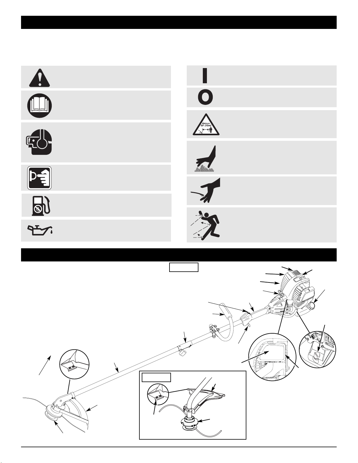
KNOW YOUR UNIT
Primer
Bulb
Oil Fill
Plug/
Dipstick
Spark Plug
Air Filter Cover
CC4175
Cutting
Attachment
Shield
CC4125
Line
Cutting
Blade
Cutting
Attachment
Shield
Fuel
Cap
Throttle
Control
J-Handle
Cutting Attachment
Shaft Grip
On/Off Stop
Control
Shaft
Housing
Starter Rope Grip
Line
Cutting
Blade
APPLICATIONS
As a trimmer:
• Cutting grass and light weeds
• Edging
• Decorative trimming around trees, fences, etc.
Other optional accessories may be used with your unit.
Refer to Operating the Rapid-Link System for a list of add-
ons.
NOTE: The below illustration may differ slightly from your
unit. For example, the picture shows a straight shaft.
Your unit may have a curved shaft.
Muffler
Spark Arrestor
Cutting
Attachment
Muffler Guard
Rapid-Link™
4
WARNING: OVERFILLING OIL CRANKCASE
MAY CAUSE SERIOUS PERSONAL INJURY. Check
and maintain the proper oil level in the crank case; it
is important and cannot be overemphasized. Check
the oil before each use and change it as needed.
See Changing the Oil.
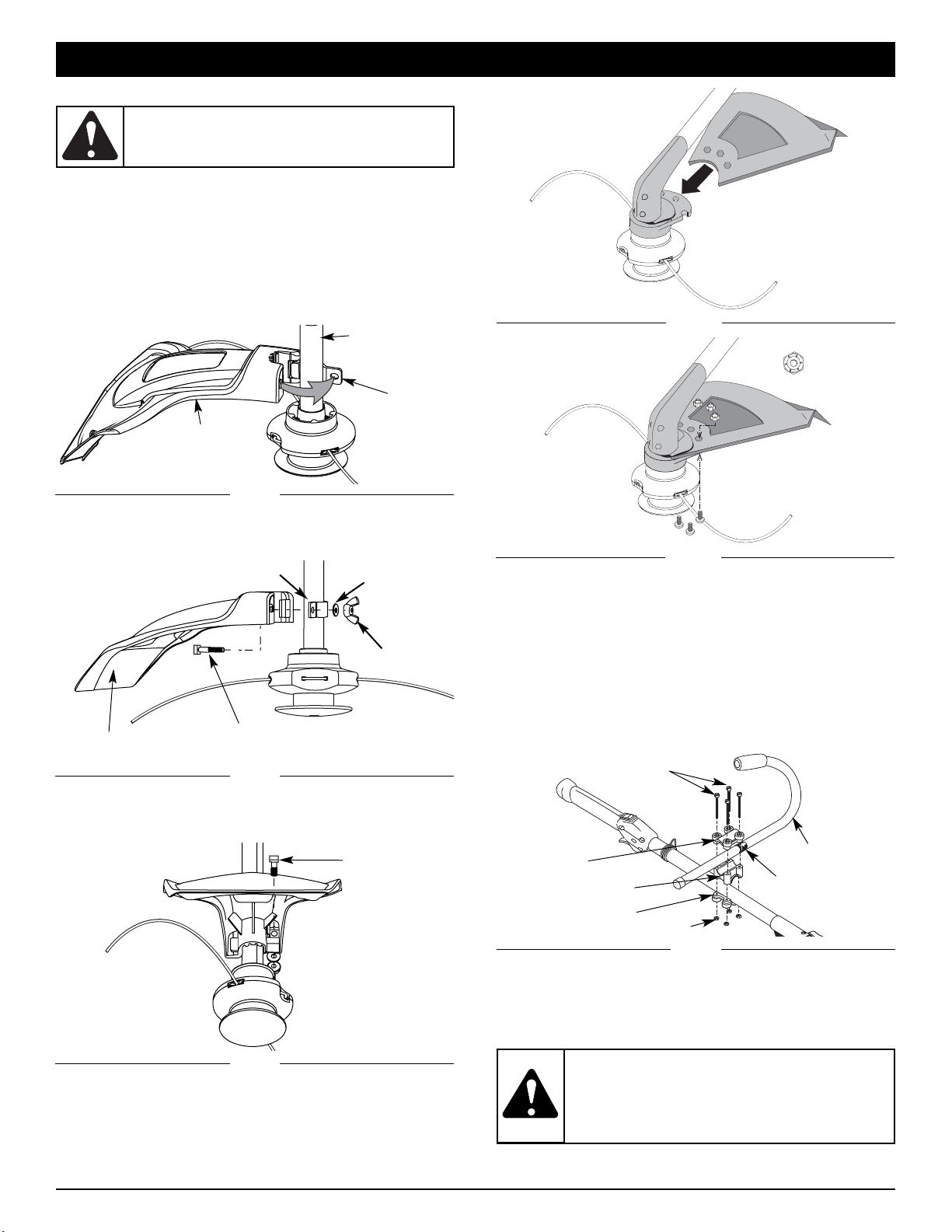
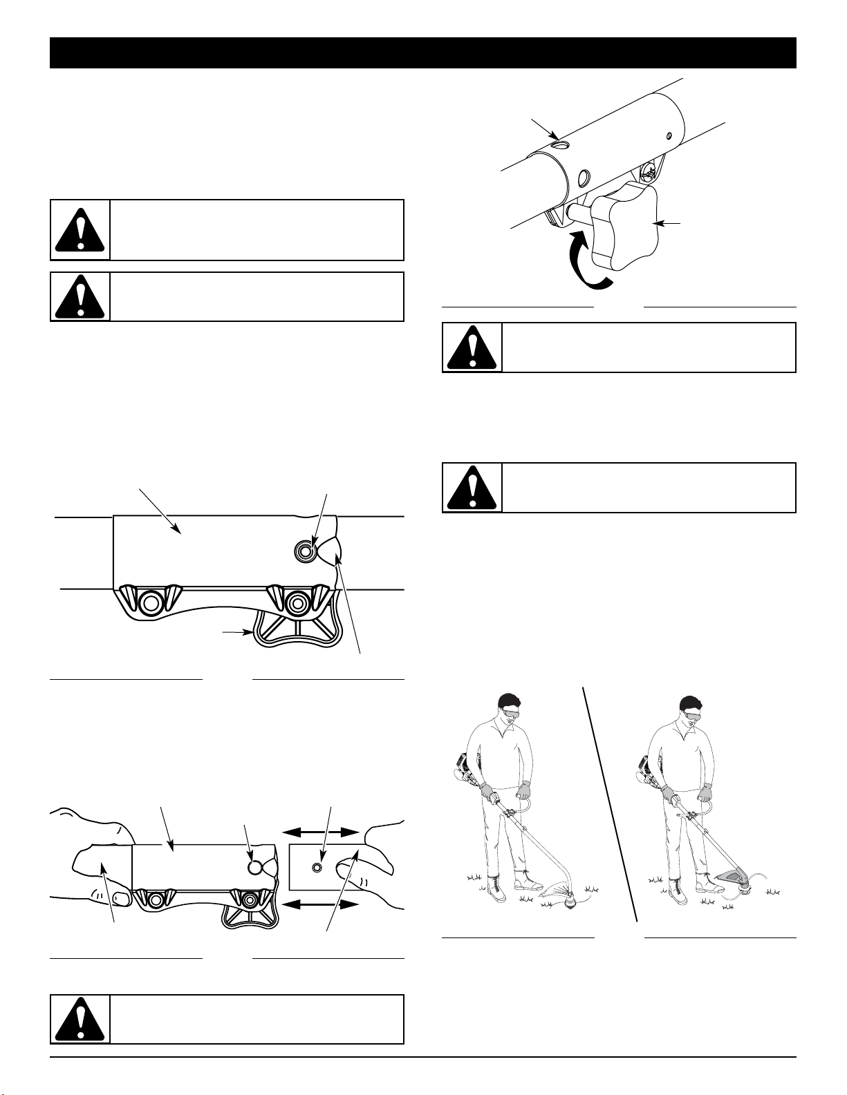
ADJUST THE J-HANDLE
1. Loosen the screws.
2.
Slide the J-handle in or out until the arrow/white line on the
decal touches the clamp assembly (Fig. 6). You must first
loosen the screws if the handle is pre-installed.
3. While holding the unit in the operating position (Fig. 18),
position the J-handle to the location that provides you the
best grip.
4. Tighten the clamp screws evenly, until the J-handle is secure.
ASSEMBLY INSTRUCTIONS
CC4175
1. Slide the cutting attachment shield into the shield mount on
the cutting attachment. Align the screw holes in the shield
with the holes in the cutting attachment (Fig. 4).
2. Place a hex lock nut into one of the three recessed holes on
the top of the cutting attachment shield (Fig 5).
Fig. 4
INSTALL CUTTING ATTACHMENT SHIELD
Use the following instructions if the cutting attachment shield
on your unit is not installed. Use only the instructions that apply
to the type of shaft and shield that your unit is equipped with.
CC4125
1. Place the cutting attachment shield onto the shaft housing.
Be sure the guard mounting bracket slides into the slot on
the edge of the cutting shield. Rotate the shield into place,
counterclockwise. The holes in the guard mounting bracket
and cutting attachment shield will line up (Fig. 1).
3. Put the washer on the bolt, then screw the wing nut onto
the bolt and tighten. Figure 3 shows the installation
process from underneath the unit.
Fig. 1
Fig. 2
Shaft Housing
Fig. 3
Bolt
Guard
Mounting
Bracket
Cutting
Attachment
Shield
Cutting Attachment
Shield
Square
Blot
Fig. 5
3. Install a screw into the hole from the bottom of the cutting
attachment shield and screw it into the nut installed in step
2 (Fig. 5). Do not tighten.
4. Repeat steps 2 and 3 until all three screws have been
started, then tighten securely.
WARNING: To prevent serious personal injury,
never operate the trimmer without the cutting
attachment shield in place.
Wing Nut
Washer
Guard Mounting Bracket
Fig. 6
Decal
(4) Screws
Top Clamp
J-Handle
Middle Clamp
Bottom Clamp
Nuts
2. From inside the cutting attachment shield, push the square
bolt through the hole until the threaded end protrudes through
the guard mounting bracket (Fig. 2).
5
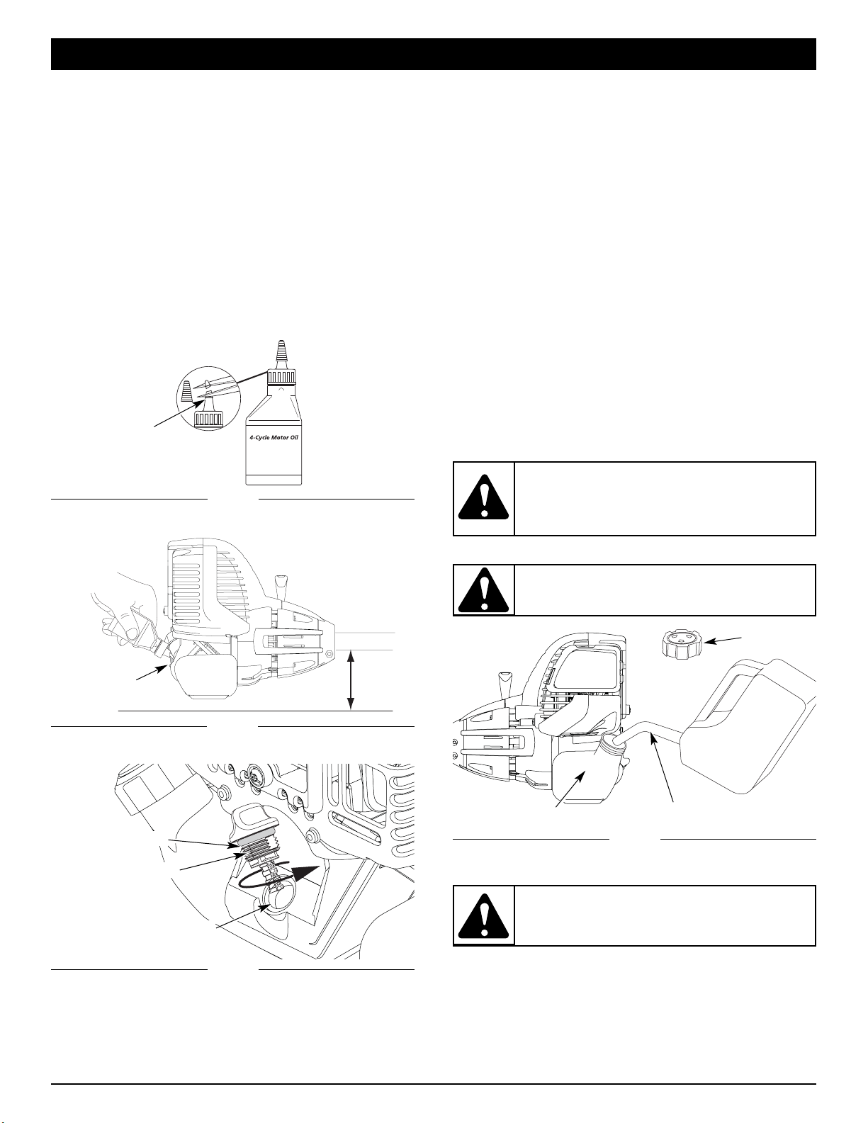
RECOMMENDED OIL TYPE
Using the proper type and weight of oil in the crankcase is extremely
important. Check the oil before each use and change the oil regularly.
Failure to use the correct oil, or using dirty oil, can cause premature
engine wear and failure. Use a high-quality SAE 30 weight oil of API
(American Petroleum Institute) service class SF, SG, SH.
ADDING OIL TO CRANKCASE: INITIAL USE
NOTE: This unit is shipped without oil. In order to avoid
damage to the unit, put oil in the crankcase before you
attempt to start the unit.
Your unit is supplied with one 3.04 fluid oz. (90 ml.)
bottle of SAE 30 SF, SG, SH oil (Fig. 7).
NOTE: Save the bottle of oil. It can be used to measure the
correct amount during future oil changes. See
Changing the Oil.
1. Unscrew the top of the bottle of oil and remove the paper
seal covering the opening. Replace the top. Next, cut the
tip off the funnel spout (Fig. 7).
2. Place the unit on a flat level surface (Fig. 8).
Fig. 7
Fig. 8
Oil Fill
Oil Fill Plug/Dipstick
Oil Fill Hole
Fig. 9
4. Pour the entire bottle of oil into the oil fill hole (Fig. 8).
NOTE: Never add oil to the fuel or fuel tank.
5. Wipe up any oil that may have spilled and reinstall the oil
fill plug / dipstick.
Check oil before each use and change as needed. Refer to
Changing the Oil.
O-Ring
Funnel Spout
OIL AND FUEL INFORMATION
RECOMMENDED FUEL TYPE
Old fuel is the primary reason for improper unit performance.
Be sure to use fresh, clean, unleaded gasoline.
NOTE: This is a four cycle engine. In order to avoid damage
to the unit, do not mix oil with gasoline.
Definition of Blended Fuels
Today's fuels are often a blend of gasoline and oxygenates such
as ethanol, methanol or MTBE (ether). Alcohol-blended fuel
absorbs water. As little as 1% water in the fuel can make fuel
and oil separate or form acids when stored. Use fresh fuel (less
than 60 days old), when using alcohol-blended fuel.
Using Blended Fuels
If you choose to use a blended fuel, or its use is unavoidable,
follow recommended precautions:
• Always use fresh unleaded gasoline
• Use the fuel additive STA-BIL
®
or an equivalent
• Drain tank and run the engine dry before storing unit
Using Fuel Additives
The use of fuel additives, such as STA-BIL
®
Gas Stabilizer or an
equivalent, will inhibit corrosion and minimize the formation of
gum deposits. Using a fuel additive can keep fuel from forming
harmful deposits in the carburetor for up to six (6) months. Add
0.8 oz. (23 ml.) of fuel additive per gallon of fuel according to the
instructions on the container. NEVER add fuel additives directly
to the unit's gas tank.
FUELING THE UNIT
1. Remove the fuel cap (Fig. 10).
Fig. 10
Fuel Tank
Gas Can Spout
2. Place the gas container’s spout into the fill hole on the fuel
tank (Fig. 10) and fill the tank.
NOTE: Do not overfill the tank.
3. Wipe up any gasoline that may have spilled.
4. Reinstall the fuel cap.
5. Move the unit at least 30 ft. (9.1 m) from the fueling source
and site before starting the engine.
NOTE: Dispose of the old gasoline in accordance to Federal,
State and Local regulations.
Unleaded
Gasoline
WARNING:
Remove fuel cap slowly to avoid
injury from fuel spray. Never operate the unit without
the fuel cap securely in place
.
WARNING: Gasoline is extremely flammable.
Ignited vapors may explode. Always stop the engine
and allow it to cool before filling the fuel tank. Do
not smoke while filling the tank. Keep sparks and
open flames at a distance from the area.
WARNING: Add fuel in a clean, well ventilated
outdoor area. Wipe up any spilled fuel immediately.
Avoid creating a source of ignition for spilt fuel. Do
not start the engine until fuel vapors dissipate.
Gas Cap
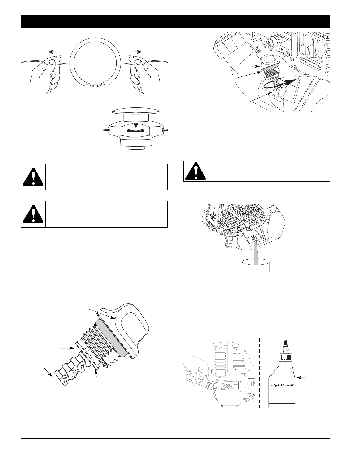
3. Remove the oil plug / dipstick from the crankcase (Fig. 9).
6
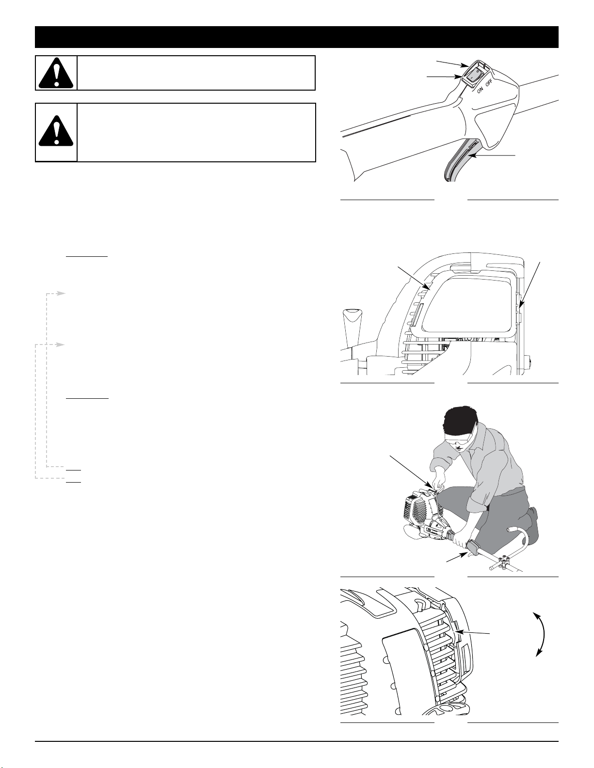
STARTING INSTRUCTIONS
STOPPING INSTRUCTIONS
1. Release your hand from the throttle control. Allow the engine to
cool down by idling.
2. Put the On/Off Stop Control in the OFF (O) position.
Primer
Bulb
Starter Rope
Throttle Control
Cold Weather
Start Lever
Cold
Weather
Start Lever
Run/ Open
Close/ Start
Fig. 11
Fig. 14
Fig. 13
Fig. 12
1. Check the oil level in the crankcase. Refer to Checking the
Oil Level.
2. Fill the fuel tank with fresh, clean unleaded gasoline. Refer
to Fueling the Unit.
NOTE: There is no need to turn the unit on. The On/Off Stop
Control is in the ON (I) position at all times (Fig. 11).
IF COLD...
For cold weather conditions (below 40°F), flip the
Cold Weather Start Lever (Fig. 14) down to the start/closed
position and continue to step 3. DO NOT flip this lever
down if the temperature is above 40°F.
3. Fully press and release the primer bulb 10 times, slowly.
Some amount of fuel should be visible in the primer bulb
and fuel lines (Fig. 12). If you can’t see fuel in the bulb,
press and release the bulb as many times as it takes before
you can see fuel in it.
4. With the unit in the starting position, do not squeeze the
throttle control (Fig. 13). Pull the starter rope out a short
distance, until you feel some resistance. This is usually
around 2-4 inches. Then pull the rope smoothly and briskly.
Repeat this 5 times. The engine should start.
IF COLD...
For cold weather conditions (below 40°F), flip the
Cold Weather Start Lever back up to the run/open
position after the unit has started and before squeezing
the throttle control.
5. Squeeze the throttle control to warm up the engine for 15 to
30 seconds. In cold weather, let the engine warm up for 30
to 60 seconds.
IF...
The engine does not start, go back to step 3.
IF...
The engine stops while you are squeezing the throttle, go
back to step 4.
STARTING / STOPPING INSTRUCTIONS
Start/On ( I )
Throttle
Control
Stop/Off (O)
WARNING: Avoid accidental starting. Make sure you are
in the starting position when pulling the starter rope
(Fig. 13).
To avoid serious injury, the operator and unit must
be in a stable position while starting.
Make sure that any
Add-On item is installed correctly and secure before
starting the unit.
WARNING:
Operate this unit only in a well- ventilated
outdoor area. Carbon monoxide exhaust fumes can be lethal
in a confined area.
7
HOLDING THE TRIMMER
Before operating the unit, stand in the operating position (Fig.
18). Check for the following:
• The operator is wearing eye protection and proper clothing
• With a slightly-bent right arm, the operator’s right hand is
holding the shaft grip
• The operator’s left arm is straight, the left hand holding the
handle
• The unit is at waist level
• The cutting attachment is parallel to the ground and easily
contacts the grass without the need to bend over
Fig. 18
Some line breakage will occur from:
• Entanglement with foreign matter
• Normal line fatigue
• Attempting to cut thick, stalky weeds
• Forcing the line into objects such as walls or fence posts
WARNING: Always wear eye, hearing, foot and
body protection to reduce the risk of injury when
operating this unit.
For edging (when using the line head cutting attachment with
Rapid-Link™ models), lock the release button of the cutting
attachment into the
90° edging hole (Fig. 17).
OPERATING THE RAPID-LINK
™
SYSTEM
The Rapid-Link™ system enables the use of this optional Add-
On:
Blower/Trimmer . . . . . . . . . . . . . . . . . . . . . . . . . . . . . . . .CCBT*
* Do NOT use this attachment with an electric powered
unit.
Removing the Cutting Attachment or Add-On
1. Turn the knob counterclockwise to loosen (Fig. 15).
2. Press and hold the release button (Fig. 15).
3. While firmly holding the upper shaft housing, pull the
cutting attachment or add-on straight out of the Rapid-
Link™ coupler (Fig. 16).
Installing the Cutting Attachment or Add-On
NOTE: Place the unit on the ground or on a work bench to
make add-on installation or removal easier.
1. Turn knob counterclockwise to loosen (Fig. 15).
Fig. 15
Rapid-Link™ Coupler
Release Button
Guide Recess
Knob
Primary Hole
Upper Shaft Housing
Rapid-Link™ Coupler
2. While firmly holding the add-on, push it straight into the
Rapid-Link™ coupler (Fig. 16).
NOTE: Aligning the release button with the guide recess will
help installation (Fig. 15).
3. Turn the knob clockwise to tighten (Fig. 17).
Fig. 16
Fig. 17
Knob
Lower Shaft Housing
Release Button
90˚ Edging Hole
(Trimmer Only)
OPERATING INSTRUCTIONS
CAUTION: Add-ons are to be used in the
primary hole only. Using the wrong hole could
lead to personal injury or damage to the unit.
WARNING: To avoid serious personal injury and
damage to the unit, shut the unit off before
removing or installing add-ons.
CAUTION: Lock the release button in the
primary hole and securely tighten the knob before
operating this unit.
WARNING: Before you begin using any
attachment, read and understand the manual that
came with the attachment. Follow all safety
information contained within.
8
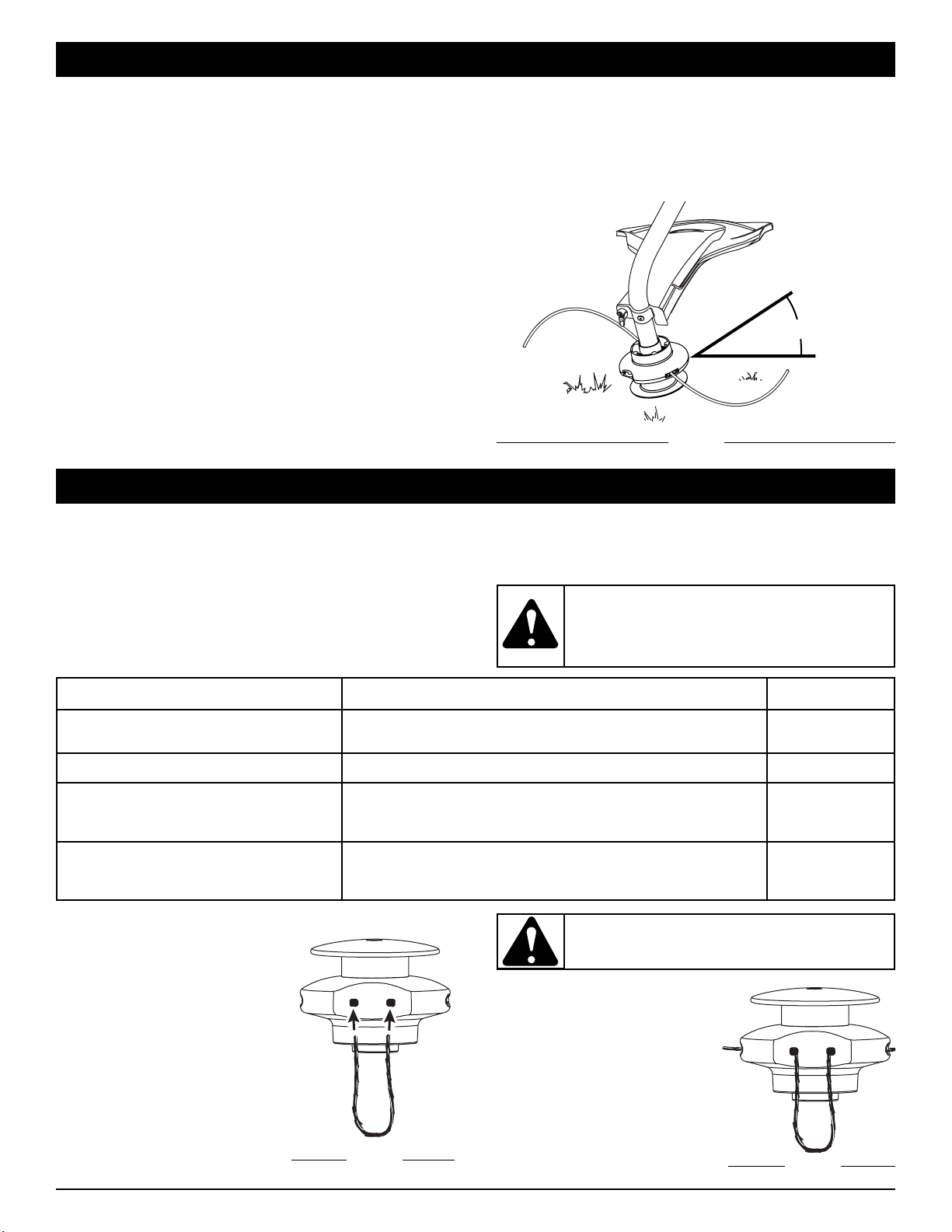
DECORATIVE TRIMMING
Decorative trimming is accomplished by removing all
vegetation around trees, posts, fences and more.
Rotate the whole unit so that the cutting attachment is at a 30°
angle to the ground (Fig. 19).
OPERATING INSTRUCTIONS
Fig. 19
30°
MAINTENANCE SCHEDULE
Perform these required maintenance procedures at the
frequency stated in the table. These procedures should also be
a part of any seasonal tune-up.
NOTE: Some maintenance procedures may require special
tools or skills. If you are unsure about these
procedures take your unit to any non-road engine
repair establishment, individual or authorized service
dealer.
NOTE: Maintenance, replacement, or repair of the emission
control devices and system may be performed by any
non-road engine repair establishment, individual or
authorized service dealer.
FREQUENCY MAINTENANCE REQUIRED REFER TO
Before starting engine
Fill fuel tank with fresh fuel
Check oil
Page 5
Page 9
Every 10 hours Clean and re-oil air filter Page 10
First change at 10 hours
At 25 hours
Every 25 hours thereafter
Change oil
Change oil
Clean spark arrestor
Page 9
Page 9
Page 13
10 hours on new engine
Every 25 hours
Every 25 hours
Check rocker arm to valve clearance and adjust
Check rocker arm to valve clearance and adjust
Check spark plug condition and gap
Page 11
Page 11
Page 13
MAINTENANCE AND REPAIR INSTRUCTIONS
WARNING: To prevent serious injury, never
perform maintenance or repairs with unit running.
Always service and repair a cool unit. Disconnect
the spark plug wire to ensure that the unit cannot
start.
TIPS FOR BEST TRIMMING RESULTS
• For best trimming results, operate unit at full throttle.
• Keep the cutting attachment parallel to the ground.
• Do not force the cutting attachment. Allow the tip of the line
to do the cutting, especially along walls. Cutting with more
than the tip will reduce cutting
efficiency and may overload the engine.
• Cut grass over 8 inches (200 mm) by working from top to
bottom in small increments to avoid premature line wear or
engine drag.
• Slowly move the trimmer into and out of the cutting area at the
desired height. Move either in a forward-backward or side-to-
side motion. Cutting shorter lengths produces the best results.
• Trim only when grass and weeds are dry.
• The life of your cutting line is dependent upon:
• Proper adherence of explained trimming techniques
• What vegetation is cut
• Where vegetation is cut
For example, the line will wear faster when trimming against a
foundation wall as opposed to trimming around a tree.
FIXED LINE INSTALLATION
Always use original equipment
manufacturer 0.105 inch (2.67 mm)
replacement line. Lines other than
those specified may make the
engine overheat or fail.
To install the trimming line:
1. Insert each end of the
replacement line into the holes
on either side of retention
hook (Fig. 20).
2. Push the ends through until
they stick out of the sides of
the head (Fig. 21).
Fig. 20
Fig. 21
WARNING: Never use metal-reinforced line, wire,
chain, or rope. These can break off and become
dangerous projectiles.
3. Pull the ends through making
sure that the ends are of
equal length and the middle
of the line is centered
between the insertion holes
(Fig. 22).
4. If the ends are not of equal
length, push the longer end
back through the head part
way and pull the shorter end to
compensate. Repeat until both
ends are the same length.
9
CHANGING THE OIL
For a new engine, change the oil after the first 10 hours of operation.
Change the oil while the engine is still warm. The oil will flow freely
and carry away more impurities.
1. Unplug spark plug boot to prevent accidental starting.
2. Remove the oil fill plug/dipstick.
3. Pour the oil out of the oil fill hole and into a container by
tipping the unit to a vertical position (Fig. 26). Allow ample
time for complete drainage.
Fig. 26
6. Replace the oil fill plug/dipstick.
7. Reconnect the spark plug boot.
4. Wipe up any oil residue on the unit and clean up any oil that
may have spilled. Dispose of the oil according to Federal,
State and local regulations.
5. Refill the crankcase with 3.04 fluid ounce (90 ml) of SAE 30
SF, SG, SH oil.
NOTE: Use the bottle and spout saved from initial use to measure
the correct amount of oil. The top of the label on the bottle
measures approximately 3.4 ounces (100 ml) (Fig. 27).
Check the level with the dipstick. If the level is low, add a
small amount of oil and recheck. Do not overfill (Fig. 27).
Fill Level
Fig. 27
CAUTION:
Wear gloves to prevent injury when
handling the unit.
CHECKING THE OIL LEVEL
The importance of checking and maintaining the proper oil level in the
crankcase cannot be overemphasized. Check oil before each use:
1. Stop the engine and allow oil to drain into the crankcase.
2. Place the unit on a flat, level surface to get a proper oil
level reading.
3. Keep dirt, grass clippings and other debris out of the
engine. Clean the area around the oil fill plug/dipstick
before removing it.
4. Remove the oil fill plug/dipstick and wipe off oil. Reinsert it
all the way back in.
5. Remove the oil fill plug/dipstick and check the oil level. Oil
should be up to the top of the dipstick (Fig. 24).
6. If the level is low, add a small amount of oil to the oil fill
hole and recheck (Fig. 25). Repeat this procedure until the
oil level reaches the top of the dipstick.
NOTE: Do not overfill the unit.
NOTE: Make sure the O-ring is in place on the oil fill plug/dipstick
when checking and changing the oil (Fig. 25).
Top of Dipstick
O-Ring
Oil Fill Plug/Dipstick
Fig. 24
Fig. 25
Oil Fill Plug/Dipstick
Oil Fill Hole
O-Ring
Full
Add 1.4-1.5 Oz.
(41-44 ml)
WARNING: To prevent extensive engine wear
and damage to the unit, always maintain the proper
oil level in the crankcase. Never operate the unit
with the oil level below the bottom of the dipstick.
WARNING: Always use the correct line length when
installing trimming line on the unit. If the two lengths of
cutting line are not of equal length, the unit may develop
a vibration.
Fig. 22
Fig. 23
5. Push the trimmer line until it
lies flat against the cutting
head (Fig. 23). Make sure the
two lengths of cutting line are
of equal length. If they are
not, adjust until they are.
MAINTENANCE AND REPAIR INSTRUCTIONS
10
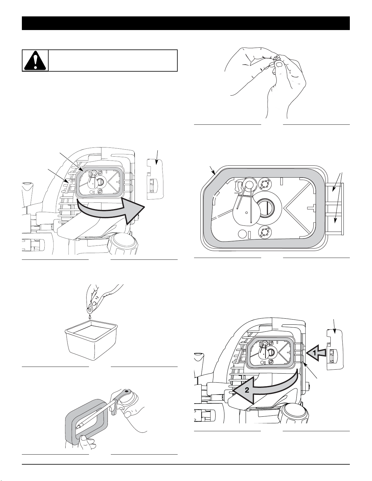
3. Wash the filter in detergent and water (Fig. 29). Rinse the
filter thoroughly and allow it to dry.
Fig. 29
AIR FILTER MAINTENANCE
Cleaning the Air Filter
Clean and re-oil the air filter every 10 hours of operation. It is an
important item to maintain. Failure to maintain your air filter
properly can result in poor performance or can cause
permanent damage to your engine.
1. Open the air filter cover. Push the tab on the left side of the
cover inward. Then pull the air filter cover out and to the
right (Fig. 28).
NOTE: It may be necessary to remove the fuel cap to
completely remove the air filter cover.
2. Remove the air filter (Fig. 28).
Air Filter
Air Filter Cover
Tab
Fig. 28
MAINTENANCE AND REPAIR INSTRUCTIONS
WARNING: To avoid serious personal injury,
always turn the unit off and allow it to cool before
you clean or service it.
4. Apply enough clean SAE 30 motor oil to lightly coat the
filter (Fig. 30).
5. Squeeze the filter to spread and remove excess oil (Fig. 31).
Fig. 32
Slots
6. Replace the filter (Fig. 32).
NOTE: If the unit is operated without the air filter, you will
VOID the warranty.
Back Plate
Fig. 31
Fig. 30
7. Reinstall the air filter cover. Position the hooks on the right
side of the air filter cover into the slots at the right side of
the back plate (Fig. 33, no.1).
8. Swing the cover to the left until the tab on the air filter
cover snaps into place in the slot on the back plate (Fig.
33, no. 2).
Cover
Hinge
Fig. 33
Air Filter Cover
11
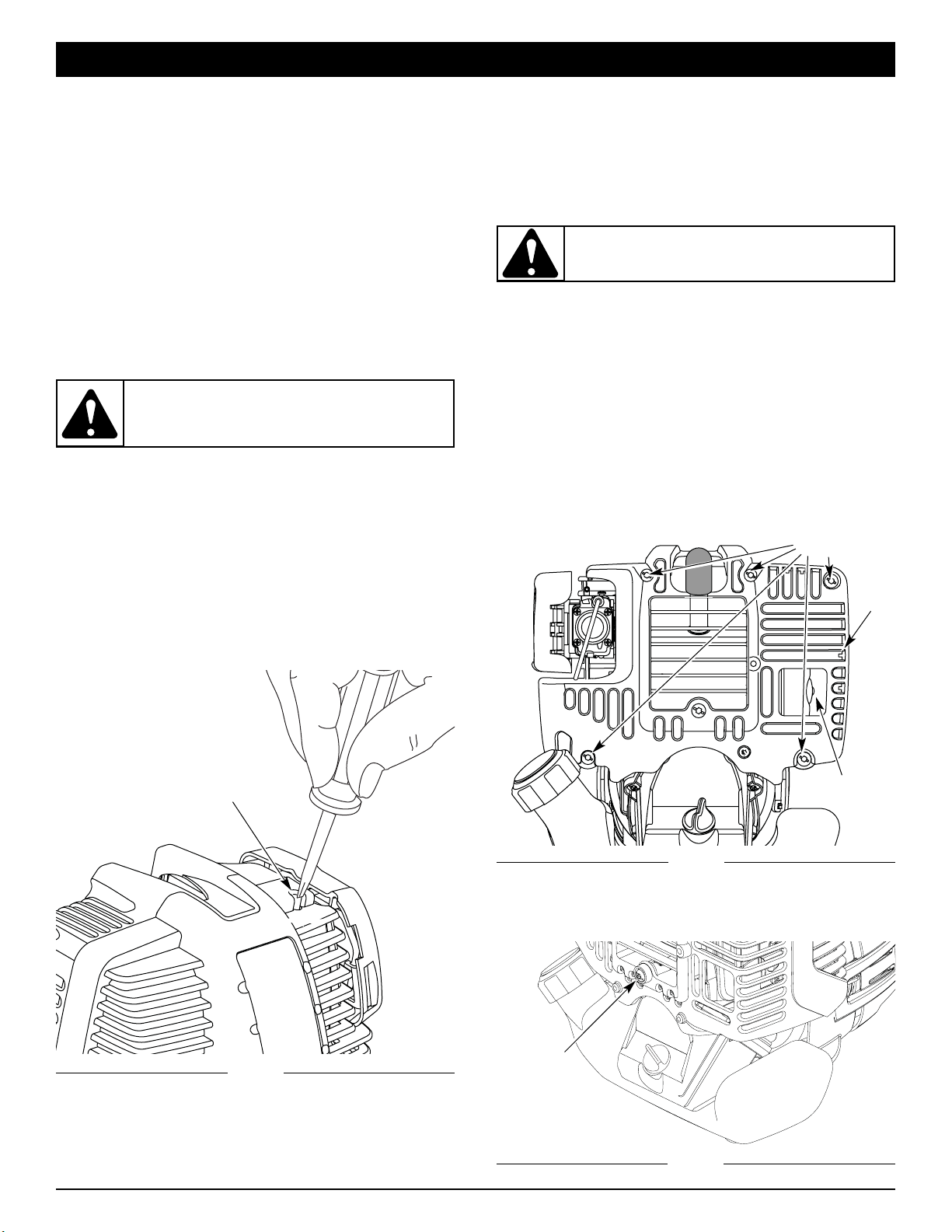
2. Remove the screw behind the engine cover with a Flat-
head or T-25 Torx screwdriver (Fig. 36).
Screw
Fig. 36
Clean Air Filter
The condition of the air filter is important to the operation of the
unit. A dirty air filter will restrict air flow. This is often mistaken
for an out of adjustment carburetor. Check the condition of the
air filter before adjusting the idle speed screw. Refer to Air
Filter Maintenance.
Adjust Idle Speed Screw
If, after checking the fuel and cleaning the air filter, the engine
still will not idle, adjust the idle speed screw as follows:
1. Start the engine and let it run at a high idle for a minute to
warm up. Refer to Starting/Stopping Instructions.
2. Release the throttle trigger and let the engine idle. If the
engine stops, insert a small phillips or flat blade screwdriver
into the hole in the air filter/muffler cover (Fig. 34). Turn the
idle speed screw in, clockwise, 1/8 of a turn at a time (as
needed) until the engine idles smoothly.
NOTE: The cutting attachment should not rotate when the
engine idles.
Fig. 34
Remove
Screws
Engine
Cover
Fig. 35
Muffler
ROCKER ARM CLEARANCE
This requires disassembly of the engine. If you feel unsure or
unqualified to perform this, take the unit to an authorized
service center.
NOTE: Inspect the valve to rocker arm clearance with a feeler
gauge after the first 10 hours of operation and then
every 25 hours of operation thereafter.
• The engine must be cold when checking or adjusting the
valve clearance.
• This task should be performed inside in a clean, dust free
area.
1. Remove the five (5) screws on back of the engine cover with
a Flat-head or T-20 Torx screwdriver (Fig. 35).
WARNING: To prevent serious personal injury,
make sure the cutting attachment has stopped
rotating before you turn it off and set it down.
WARNING: The cutting attachment may spin
during idle speed adjustments. Wear protective
clothing and observe all safety instructions to
prevent serious personal injury.
Idle Ajustment
Screw
MAINTENANCE AND REPAIR INSTRUCTIONS
CARBURETOR ADJUSTMENT
The idle speed of the engine is adjustable. An idle adjustment
screw is reached though a hole in the top of the engine cover
(Fig. 34).
NOTE: Careless adjustments can seriously damage your unit.
An authorized service dealer should make carburetor
adjustments.
Check Fuel
Old fuel is usually the reason for improper unit performance.
Drain and refill the tank with fresh fuel prior to making any
adjustments. Refer to Oil and Fuel Information.
3. If the cutting attachment rotates when the engine idles, turn
the idle speed screw counterclockwise 1/8 of a turn at a time
(as needed), to reduce idle speed.
Checking the fuel, cleaning the air filter, and adjusting the idle
speed should solve most engine problems. If not and all of the
following are true:
• the engine will not idle
• the engine hesitates or stalls on acceleration
• there is a loss of engine power
Have the carburetor adjusted by an authorized service dealer.
12
3. Disconnect the spark plug wire.
4. Clean dirt from around the spark plug. Remove the spark
plug from the cylinder head by turning a 5/8 in. socket
counterclockwise.
5. Remove the engine cover (Fig. 35 & 36).
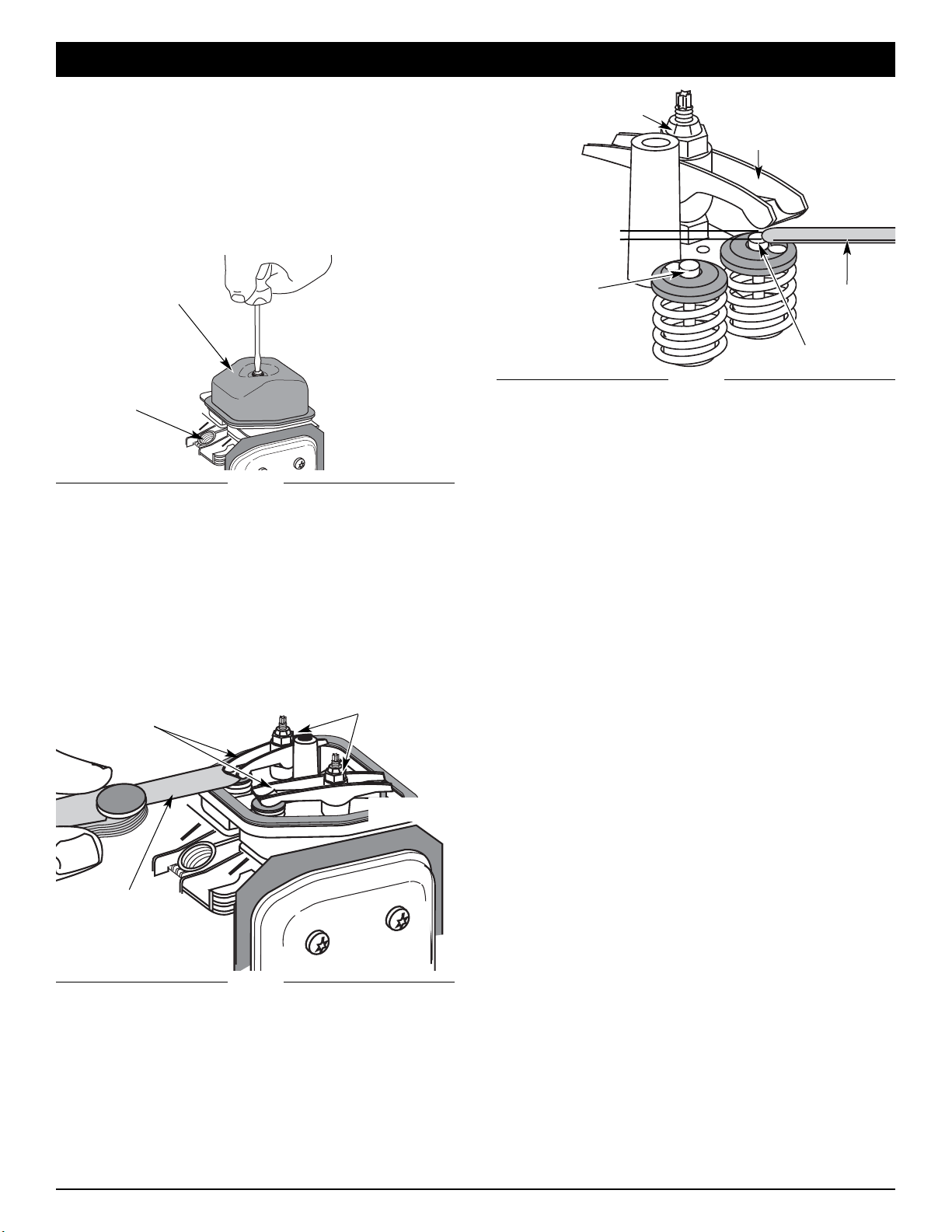
6. Clean dirt from around the rocker arm cover. Remove the
screw holding the rocker arm cover with a large flat blade
screwdriver or Torx T-25 bit (Fig. 37). Remove the rocker
arm cover and gasket.
MAINTENANCE AND REPAIR INSTRUCTIONS
Rocker Arm Cover
Fig. 37
Spark Plug Hole
7. Pull the starter rope slowly to bring the piston to the top of its
travel, (known as top dead center). Check that:
• The piston is at the top of its travel while looking in the
spark plug hole (Fig. 37)
• Both rocker arms move freely, and both valves are closed
If these statements are not true, repeat this step.
8. Slide the feeler gauge between the rocker arm and the
valve return spring. Measure the clearance between the
valve stem and rocker arm (Fig. 38). Measure both the
intake and exhaust valves.
Adjusting Nuts
Feeler Gauge
Rocker Arms
Fig. 38
9. If the clearance is not within specification:
a. Turn the adjusting nut using a 5/16 inch (8 mm) wrench or
nut driver (Fig. 39).
• To increase clearance, turn the adjusting nut
counterclockwise.
• To decrease clearance, turn the adjusting nut
clockwise.
b. Recheck both clearances, and adjust as necessary.
10. Reinstall the rocker arm cover using a new gasket. Torque
the screw to 20–30 in•lb (2.2–3.4 N•m).
11. Reinstall the engine cover. Check alignment of the cover
before tightening the screws. Tighten screws.
12. Reinstall the muffler cover. Slip the rear tab on the muffler
cover into the engine cover rear slot. Then slide the
remaining slots into the tabs until they snap into place
(Fig. 33).
13. Check the spark plug and reinstall. See Replacing the
Spark Plug.
14. Replace the spark plug wire.
INTAKE
EXHAUST
Fig. 39
Feeler Gauge
Exhaust
Adjusting Nut
Exhaust
Rocker Arm
Exhaust Valve Stem
Intake Valve
Stem
0.003–0.006 in.
(0.076–0.152 mm)
The recommended clearance for both intake and exhaust is
.003 – .006 in. (.076 – 0.152 mm). Use a standard automotive
.005 in. (0.127 mm) feeler gauge. The feeler gauge should slide
between the rocker arm and valve stem with a slight amount of
resistance, without binding. Figure 38 and 39 show how to
measure the clearance.
13
CLEANING
Use a small brush to clean off the outside of the unit. Do not
use strong detergents. Household cleaners that contain
aromatic oils such as pine and lemon, and solvents such as
kerosene, can damage plastic housing or handle. Wipe off any
moisture with a soft cloth.
STORAGE
• Never store the unit with fuel in the tank where fumes may
reach an open flame or spark.
• Allow the engine to cool before storing.
• Lock up the unit to prevent unauthorized use or damage.
• Store the unit in a dry, well-ventilated area.
• Store the unit out of the reach of children.
LONG TERM STORAGE
1. Drain all gasoline from the gas tank into a container. Do not
use gas that has been stored for more than 60 days.
Dispose of the old gasoline in accordance to Federal,
State, and Local regulations.
2. Start the engine and allow it to run until it stalls. This
ensures that all gasoline has been drained from the
carburetor.
3. Allow the engine to cool. Remove the spark plug and put 5
drops of high quality motor oil into the cylinder. Pull the
starter rope slowly to distribute the oil. Reinstall the spark
plug.
NOTE: Remove the spark plug and drain all of the oil from the
cylinder before attempting to start the trimmer after
storage.
4. Change the oil, referring to Changing the Oil. Dispose of
the old oil in accordance to Federal, State and Local
regulations.
5. Thoroughly clean the unit and inspect for any loose or
damaged parts. Repair or replace damaged parts and
tighten loose screws, nuts or bolts. The unit is ready for
storage.
TRANSPORTING
• Allow the engine to cool before transporting.
• Secure the unit while transporting.
• Drain the gas tank before transporting.
• Tighten gas cap before transporting.
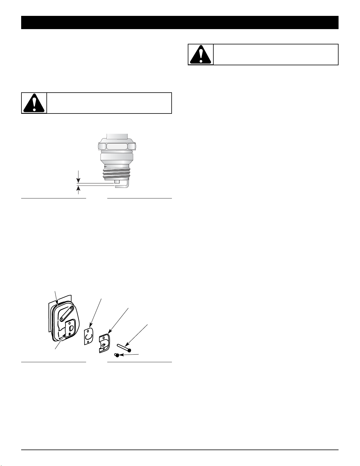
0.025 in.
(0.635 mm.)
REPLACING THE SPARK PLUG
Use a replacement part number 791-180852B spark plug. The
correct air gap is 0.025 in. (0.635 mm.). Remove the plug after
every 25 hours of operation and check its condition.
1. Stop the engine and allow it to cool. Grasp the plug wire
firmly and pull the cap from the spark plug.
2. Clean dirt from around the spark plug. Remove the spark
plug from the cylinder head by turning a 5/8 in. socket
counterclockwise.
3. Replace cracked, fouled or dirty spark plug. Set the air gap at
0.025 in. (0.635 mm.) using a feeler gauge (Fig. 40).
Fig. 40
4. Install a correctly-gapped spark plug in the cylinder head.
Turn the 5/8 in. socket clockwise until snug.
If using a torque wrench torque to:
110-120 in.•lb. (12.3-13.5 N•m)
Do not over tighten.
SPARK ARRESTOR MAINTENANCE
1. Remove the muffler cover. See Rocker Arm Clearance.
2. With a flat blade screwdriver or Torx T-20 bit and a T-25
bit, remove the screws attaching the spark arrestor
diverter to the muffler (Fig. 41).
3. Pull the tab on the spark arrestor cover out of the muffler.
Remove the spark arrestor cover.
4. Remove the spark arrestor screen from the spark arrestor
cover.
5. Clean the spark arrestor screen with a wire brush or
replace it.
6. Reinstall the spark arrestor screen, spark arrestor cover
and screw.
MAINTENANCE AND REPAIR INSTRUCTIONS
WARNING: Do not sand blast, scrape or clean
electrodes. Grit in the engine could damage the
cylinder.
WARNING: To avoid serious personal injury,
always turn your unit off and allow it to cool before
you clean or service it.
Fig. 41
Muffler
Spark Arrestor Screen
Diverter
T-20 Screw
Slot
T-25 Screw

14
CAUSE ACTION
Empty fuel tank Fill fuel tank with fuel
Primer bulb wasn't pressed enough Press primer bulb fully and slowly 10 times
Old fuel Drain gas tank and add fresh fuel
Fouled spark plug Replace or clean the spark plug
Plugged spark arrestor Clean or replace spark arrestor
When it is above 40°F outside & the Cold Weather Start Lever
is in the CLOSED / START position
Flip the Cold Weather Start Lever to RUN / OPEN
When it is below 40°F outside & the Cold Weather Start Lever
is in the RUN / OPEN position
Flip the Cold Weather Start Lever to CLOSED / START and
follow the Starting Instructions
ENGINE WILL NOT START
ENGINE WILL NOT ACCELERATE
TROUBLESHOOTING
CAUSE ACTION
Air filter is plugged Replace or clean the air filter
Old fuel Drain gas tank and add fresh fuel
Improper carburetor adjustment Adjust according to the Carburetor Adjustments section or take
to an authorized service dealer for an adjustment
CAUSE ACTION
Old fuel Drain gas tank and add fresh fuel
Improper carburetor adjustment Adjust according to the Carburetor Adjustments section or take
to an authorized service dealer for an adjustment
Fouled spark plug Replace or clean the spark plug
Plugged spark arrestor Clean or replace spark arrestor
CAUSE ACTION
Old fuel Drain gas tank and add fresh fuel
Improper carburetor adjustment Adjust according to the Carburetor Adjustments section or take
to an authorized service dealer for an adjustment
Cutting attachment bound with grass Stop the engine and clean the cutting attachment
Dirty air filter Clean or replace the air filter
Plugged spark arrestor Clean or replace spark arrestor
If further assistance is required, contact your authorized service dealer.
ENGINE LACKS POWER OR STALLS WHEN CUTTING
ENGINE WILL NOT IDLE

15
* All specifications are based on the latest product information available at the time of printing. We reserve the right to make changes
at any time without notice.
Drive Shaft Housing............................................................................................................................................ Steel Tube (Rapid-Link™)
Throttle Control ............................................................................................................................................................... Finger-Tip Trigger
Approximate Unit Weight (No fuel, with handle, shield and cutting attachment) CC4125............................................... 11.7 lbs (6 kg)
CC4175..............................................14.5 lbs (6.5 kg)
Cutting Mechanism ............................................................................................................................................... Fixed Line Cutting Head
Line Spool Diameter: .................................................................................................................................................... 3 inches (76.2 mm)
Trimming Line Diameter: ....................................................................................................................................... 0.105 inches (2.67 mm)
Cutting Path Diameter .............................................................................................................................................. 16 inches (406.4 mm)
Engine Type................................................................................................................................................................. Air-Cooled, 4-Cycle
Displacement................................................................................................................................................................ 1.6 cu. in. (26.2 cc)
Clutch Type ................................................................................................................................................................................ Centrifugal
Operating RPM............................................................................................................................................................... 6,800 - 9,300 rpm
Idle Speed RPM ............................................................................................................................................................. 2,800 - 3,600 rpm
Ignition Type................................................................................................................................................................................. Electronic
Ignition Switch .......................................................................................................................................................................Rocker Switch
Valve clearance..................................................................................................................................... 0.003–0.006 in. (0.076–0.152 mm)
Spark Plug Gap ....................................................................................................................................................... 0.025 inch (0.635 mm)
Lubrication .................................................................................................................................................................................. SAE 30 Oil
Crankcase Oil Capacity....................................................................................................................................................... 3.04 oz (90 ml)
Fuel.............................................................................................................................................................................................. Unleaded
Carburetor.............................................................................................................................................................. Diaphragm, All-Position
Starter...................................................................................................................................................................................... Auto Rewind
Muffler ............................................................................................................................................................................ Baffled with Guard
Throttle...................................................................................................................................................................... Manual Spring Return
Fuel Tank Capacity............................................................................................................................................................... 18 oz (532 ml)
SPECIFICATIONS
DRIVE SHAFT AND CUTTING ATTACHMENT*
ENGINE*
 Loading...