

Page 1
Service Manual
NOTE: These materials are for use by trained technicians experienced in the service and repair of outdoor power equipment of
the kind described in this publication, and are not intended for use by untrained or inexperienced individuals. These materials
are intended to provide supplemental information to assist the trained technician. Untrained or inexperienced individuals should
seek the assistance of an experienced and trained professional. Read, understand, and follow all instructions and use common
sense when working on power equipment. This includes the contents of the product’s Operators Manual, supplied with the
equipment. No liability can be accepted for any inaccuracies or omission in this publication, although care has been taken to
make it as complete and accurate as possible at the time of publication. However, due to the variety of outdoor power
equipment and continuing product changes that occur over time, updates will be made to these instructions from time to time.
Therefore, it may be necessary to obtain the latest materials before servicing or repairing a product. The company reserves the
right to make changes at any time to this publication without prior notice and without incurring an obligation to make such
changes to previously published versions. Instructions, photographs and illustrations used in this publication are for reference
use only and may not depict actual model and component parts. © Copyright 2005 MTD Products Inc. All Rights Reserved.
SELF PROPELLED CHIPPER VAC - CSV 070
MTD Products LLC - Product Training and Education Department
FORM NUMBER 769-01422
5/2004
Page 2

Page 3

TABLE OF CONTENTS
Safety Switch ..............................................................................................................................1
Inspection of the Drive System ...................................................................................................3
Transmission Removal ...............................................................................................................5
Impeller and Belt Removal .........................................................................................................8
Chipper Blade Removal ...........................................................................................................11
0
Page 4

Page 5
Self-propelled Chipper Shredder Vacuum
Self-propelled Chipper Shredder Vacuum
ABOUT THIS SECTION:
In model year 2000, MTD introduced a vertical crankshaft lawn vacuum with a 22” clearing width and the
capacity to shred small yard debris. Since it’s introduction, the product has been enhanced with a removable
vacuum hose. The latest product improvement is the
addition of a self-propell feature.
NOTE: The equipment that was used to write
this section was a prototype. There may be subtle differences between prototypes and production equipment.
1. SAFETY SWITCH
The safety switch is located at the rear of the unit. The
intent is to make sure that it will not run without a collection bag or blower chute in place. The safety switch
is a normally closed switch. This means that when the
bag or chute are not present, the plunger will be up,
and the contacts within the switch will be closed.
The switch is mounted to the upper impeller housing
assembly. A magneto primary wire connects to one terminal of the safety switch. The other terminal of the
safety switch is connected to a ground wire. When the
collection bag or blower chute is on the unit, the safety
switch plunger will be depressed, and the contacts will
be separated.
NOTE: A multimeter or continuity tester can be
used for this section.
1.1. Confirm that the metal tab on the collection bag
or chute depress the plunger far enough to open
the contacts in the switch.
1.2. Disconnect the switch from the magneto primary
wire at the bullet connector.
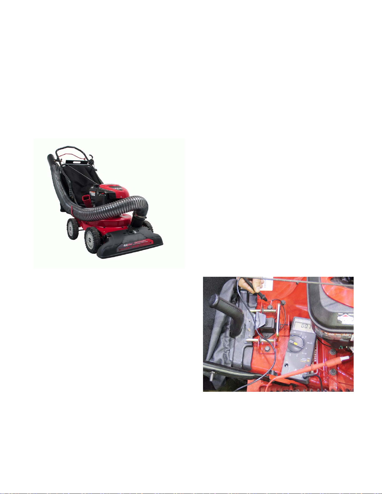
1.3. Check for continuity through the switch, from the
bullet connector to ground. See Figure 1.3.
For the sake of orientation:
• All engine controls are located on the
engine.(i.e. choke and throttle)
• The variable speed lever is on the left side of the
handle. This is NOT a throttle control.
• The variable speed lever will not move easily
unless the engine crankshaft is rotating. Do NOT
force the lever.
• The control Bail mounted to the handlebar
engages the drive system. It does NOT turn-off
the engine like the blade control handle on a
mower.
Figure 1.3
NOTE: In figure 1.3, the meter shows continuity
(near 0 ohms). This engine will not start even
though the bag is in place.
1
Page 6

Self-propelled Chipper Shredder Vacuum
1.4. If slight pressure on the tab breaks continuity,
adjusting the tab by bending it downward will
enable the switch to work correctly.
See Figure 1.4.
Figure 1.4
1.5. If the switch does not break the ground path
(meter reading: near 1.0 ohms, or “OL” indicates
open contacts, breaking ground path) when the
plunger is pressed, replace the switch.
1.8. If the switch fails to ground the magneto, identify
if the switch itself is at fault, or if a bad connection exists between the switch and ground.
NOTE: A lock tab secures the plug to the switch.
The switch must be removed to reach the lock
tab.
1.9. Remove the switch from the frame using a 5/16”
wrench or driver. See Figure 1.9.
Figure 1.9
1.6. The switch should complete a path from the
magneto to ground when the plunger is up.
See Figure 1.6.
Figure 1.6
NOTE: If the switch fails to ground out the mag-
neto when the plunger is up, it would be possible
to run the engine without a blower chute or collector bag in place. This is unsafe.
1.10. Test the switch independently. It should show
continuity with the plunger up. See Figure 1.10.
Figure 1.10
1.7.
2
Page 7

Self-propelled Chipper Shredder Vacuum
1.11. The switch should not show continuity when the
plunger is pressed. See Figure 1.11.
Figure 1.11
NOTE: “OL” meter reading in Figure 1.11 indi-
cates no continuity. Other meters may read near
1 ohm.
2. INSPECTION OF THE DRIVE SYSTEM
2.1. Begin with an operational test. Does the drive
system operate over the full range of speeds?
2.2. Remove belt cover using a 3/8” wrench.
See Figure 2.2.
Mounting Bolts
for Belt Cover
Belt Cover
Figure 2.2
1.12. If the switch works correctly, but does not ground
the magneto, the problem lies in the wiring or the
ground connection.
1.13. Do not return a machine to service unless this
safety feature works correctly.
2.3. Inspect variable speed pulley for full movement.
Run the self propel mechanism though its full
range of speeds. See Figure 2.3.
NOTE: clutch cable
connects to front
hole in bail.
Self propel
clutch bail
Speed control lever
Figure 2.3
• The crankshaft must be turning for the variable
speed mechanism to respond to the control
lever.This can be done with the engine running
or by pulling the engine through manually.
• The belt and pulley system operates whenever
the engine is running. The variable speed function can be tested without pulling up the self-propel bail to engage the clutch.
3
Page 8

Self-propelled Chipper Shredder Vacuum
2.4. Watch the travel of the variable speed sheave
(pulley) on the input shaft. It may be necessary
to remove the belt to confirm that the variable
speed sheave has full travel. See Figure 2.4.
Low speed position: High speed position:
Sheaves together Sheaves apart
Figure 2.4
NOTE: Belt removed for clarity in figure 2.4
2.5. Confirm that the belt is routed properly.
2.6. Watch the reaction of the two idler pulleys. If the
bracket that they are mounted to does not pivot
freely in response to the changes in belt tension
created by the movement of the variable speed
sheaves, the full range of speeds will not be
available, and accelerated component wear will
result. See Figure 2.6.
2.7. If the idler pulleys do not react properly, confirm
that the spring is properly attached to tension
bracket and spring anchor bolt. See Figure 2.7.
Spring anchor bolt
Spring
Figure 2.7
2.8. If the belt and pulley system works properly,
turning the variable speed sheave on the transmission input shaft, but fails to drive the wheels
when the self propel bail is lifted, then there may
be a problem in one of three areas:
• The cable that connects the bail to the clutch
mechanism.
• The final drive gears within the wheels.
• There may be an internal problem with the dog
clutch in the transmission. If there is an internal
transmission problem, replace the transmission.
Spring
Belt tensioner
2.9. To check the final drive gears, remove both rear
hubcaps. Remove the rear wheels using a 9/16”
wrench and a 1/2” wrench.
2.10. Check the condition of the teeth on the back of
the wheel.
Safety switch
Figure 2.6
4
Page 9

Self-propelled Chipper Shredder Vacuum
2.11. Confirm that the drive gears are installed on the
correct side. See Figure 2.11.
Right hand drive gear
Figure 2.11
NOTE: There is an “R” on the right side gear and
an “L” on the left side gear.
2.12. Remove retaining ring and gear to assure dowel
pin is in place. See Figure 2.12.
3. TRANSMISSION REMOVAL
3.1. Disconnect the H.T. lead from the spark plug.
3.2. Remove collection bag or blower chute.
3.3. Remove vacuum hose if attached.
3.4. Using a 3/8” socket, remove the 3 self tapping
screws securing the belt cover. See Figure 3.4.
Self tapping screws
Figure 3.4
Right side gear
Drive axle
Pin
Figure 2.12
NOTE: The pin must be free to slide back and
forth. This provides a ratcheting action.
NOTE: Apply anti-sieze to pin to ensure proper
ratcheting action.
3.5. Insert a 3/8” breaker bar and extension into the
square hole of the tensioner arm.
See Figure 3.5.
Tensioner
Arm
Square hole
Figure 3.5
3.6. Pull the breaker bar rearward until the drive belt
can be slipped over the variable pulley easily
5
Page 10

Self-propelled Chipper Shredder Vacuum
3.7. Safely support rear of the unit so that the rear
wheels are off the ground, and remove rear hub
caps. See Figure 3.7.
4X4 supports
Figure 3.7
3.8. Using a 1/2” wrench and a 9/16” wrench remove
the shoulder bolts, washers, and rear wheels.
See Figure 3.8.
3.10. Remove retaining ring holding drive gear and
dowel pin on axle. See Figure 3.10.
Dust cover
Right hand drive gear
Figure 3.10
NOTE: There are right hand and left hand drive
gears
3.11. Remove dust cover
NOTE: Rim on dust cover faces outboard
Dust cover
Heavy washer
Figure 3.8
NOTE: A heavy washer goes between wheel
and outside of frame.
3.9. Cross-bar is also secured by the rear wheel
shoulder bolts. It can be removed as the rear
wheels are removed.
NOTE: The rear cross bar is shorter than the
front cross bar.
3.12. Remove E-clip and flat washer from axle.
See Figure 3.12.
E-clip
Flat washer
Bushing
Figure 3.12
6
Page 11

Self-propelled Chipper Shredder Vacuum
3.13. Remove three self tapping screws holding transmission brace to the frame using an 3/8 socket.
3.14. Remove the two phillips screws holding the
transmission to the brace. See Figure 3.14.
Self tapping screws
Phillips screw
Figure 3.14
3.15. Remove barbed fitting holding the variable
speed cable to the transmission bracket.
See Figure 3.15.
3.17. Remove spring from transmission actuating arm.
(This is the self propel clutch cable)
See Figure 3.17.
Actuating arm
Self propel clutch cable
Figure 3.17
3.18. Push the hexagonal drive axle bushings out of
each side of frame. See Figure 3.18.
Bushing
Variable speed cable
Barbed
fitting
Figure 3.15
3.16. Disconnect Z-fitting from transmission using
needle nose pliers (This is the variable speed
cable).
NOTE: Rotating the collar counter-clockwise will
aid in removal.
NOTE: Z-fitting must be installed from the bottom of the speed control collar.
Figure 3.18
7
Page 12

Self-propelled Chipper Shredder Vacuum
3.19. Pivot transmission rearward while sliding it to the
right. See Figure 3.19.
Self propelled transmission
Figure 3.19
3.20. Once the left side comes out, slide the transmission to the left. At this point the transmission will
be solely in your hands
3.21. Install new transmission in opposite order that
was taken out.
4. IMPELLER AND BELT REMOVAL
4.1. Disconnect the H.T. lead from the spark plug.
4.2. Remove the transmission as described in the
TRASMISSION REMOVAL section of this manual.
4.3. Safely tilt and support the front of unit to provide
access to the front wheel and nozzle mounting
hardware.
4.4. Remove the hub caps.
4.5. Remove front wheels using an 1/2 wrench.
4.6. Using a 15/16” wrench and a 9/16” wrench
remove height adjusters and cross bar.
See Figure 4.6.
Height adjuster
Cross bar
Figure 4.6
NOTE: The front cross bar is longer than the
rear cross bar
8
Page 13

Self-propelled Chipper Shredder Vacuum
4.7. Use a 1/4” wrench to remove the three Screws
securing the black plastic nozzle to the lower
housing. They are accessible from underneath.
See Figure 4.7.
Black plastic nozzle
1/4” Screws
Figure 4.7
4.8. Four phillips head screws secure the front of the
nozzle to the frame. Remove them.
See Figure 4.8.
4.9. Tilt top of black plastic nozzle toward the engine
to remove. This will allow the safety gate to pass
by the hose opening freely. See Figure 4.9.
Nozzle
Engine
Safety gate within
vacuum tube
Figure 4.9
4.10. Remove all of the fasteners holding the lower
housing to the upper housing. See Figure 4.10.
Nozzle Mounting
Screws
Figure 4.8
Lower housing
Nut & bolt
Figure 4.10
NOTE: There is a variety of nuts, bolts, and self-
tapping screws holding the two housings
together.
9
Page 14

Self-propelled Chipper Shredder Vacuum
4.11. Block the impeller with a chock, to keep it from
rotating. Using a 9/16” socket, remove the bolt,
lock washer, and flat washer securing the impeller to the crankshaft. See Figure 4.11.
Bolt
Impeller
Chock
Figure 4.11
4.12. Lubricate the impeller removal tool (part number
753-0638). Thread the tool into the crankshaft
until the impeller assembly can easily slide off
the crankshaft.
4.15. In servicing the impeller:
• The pulley hub can be pried off and replaced or
reused.
• The Chipper blade can be replaced with out
removing the impeller. Refer to CHIPPER
BLADE REMOVAL section of the manual.
• The roll pins secure the clevis pins that mount
the flails. The roll pins are shielded by pin clips.
4.16. Pull belt though hole surrounding the crankshaft
to remove it.
Drive belt
NOTE: Push the belt forward to create slack,
releasing the belt from the groove in the pulley
hub.
4.13. Inspect impeller, pulley hub, chipper blade, and
flails for any damage, replace as needed.
Pulley hub
Chipper blade
Figure 4.13
Figure 4.16
4.17. Install a new belt though the hole surrounding
the crankshaft.
NOTE: When installing impeller make certain
belt is seated in the pulley groove.
NOTE: Torque the impeller bolt to 375 to 425
inch pounds.
4.14. Do not use an impeller that shows any signs of
damage. A burst hazard will result.
10
Page 15

Self-propelled Chipper Shredder Vacuum
5. CHIPPER BLADE REMOVAL
5.1. Disconnect H.T. lead from the spark plug.
5.2. Remove the three bolts holding the chipper
chute to the upper housing. See Figure 5.2.
Chipper chute
Figure 5.2
5.3. Remove the black plastic nozzle as described in
the BELT AND IMPELLER REMOVAL section
of this manual. See Figure 5.3.
5.4. Using 3/16” allen wrench, remove the flat head
cap screw that holds the chipper blade to the
impeller. It is accessible through the opening
created by removing the chipper chute.
See Figure 5.4.
3/16 allen wrench
Figure 5.4
5.5. The nuts on the flat head cap screws can be
reached using a 1/2” socket, universal, and
extension. See Figure 5.5.
Figure 5.3
Engine
Impeller
Figure 5.5
NOTE: On installation, torque the chipper blade
to 210 - 250 inch pounds.
11
 Loading...