

MTD A"", \""B\"" Professional Shop Manual

Professional Shop Manual
“A” and “B” Series Mowers
NOTE: These materials are for use by trained technicians who are experienced in the service and repair of outdoor power
equipment of the kind described in this publication, and are not intended for use by untrained or inexperienced individuals.
These materials are intended to provid e su pp lem ental information to assist the trained technician. Untrained or inexperienced individuals should seek the assistance of an experienced and tr ained professional. Read, understand, a nd follow all
instructions and use common sense when working on power equipment. This includes the contents of the product’s Operators Manual, supplied with the equipment. No liability can be accepted for any inaccuracies or omission in this publication,
although care has been taken to make it as complete a nd accura te as possib le at the time of publica tion. However, due to
the variety of outdoor power equipment and continuing product changes that occur over time, updates will be made to these
instructions from time to time. Therefore, it may be necessary to obtain the latest materials before servicing or repairing a
product. The company reserves the right to make changes at any time to this publication without prior notice and without
incurring an obligation to make such changes to previously published versions. Instructions, photographs and illustrations
used in this publication are for reference use only and may not depict actual model and component parts.
© Copyright 2010 MTD Products Inc. All Rights Reserved
MTD Products Inc - Product Training and Education Department
FORM NUMBER - 769-05615A
03/2010


Chapter 1: Introduction ......................................................................................................1
About the text format . . . . . . . . . . . . . . . . . . . . . . . . . . . . . . . . . . . . . . . . . . . . . . . . . . . .1
Safety . . . . . . . . . . . . . . . . . . . . . . . . . . . . . . . . . . . . . . . . . . . . . . . . . . . . . . . . . . . . . . . .2
Fasteners . . . . . . . . . . . . . . . . . . . . . . . . . . . . . . . . . . . . . . . . . . . . . . . . . . . . . . . . . . . . .3
Assembly instructions . . . . . . . . . . . . . . . . . . . . . . . . . . . . . . . . . . . . . . . . . . . . . . . . . . .3
The “A” series mower . . . . . . . . . . . . . . . . . . . . . . . . . . . . . . . . . . . . . . . . . . . . . . . . . . 4
The “B” series mower . . . . . . . . . . . . . . . . . . . . . . . . . . . . . . . . . . . . . . . . . . . . . . . . . . .4
Understanding model and serial numbers . . . . . . . . . . . . . . . . . . . . . . . . . . . . . . . . . . . .5
Maintenance chart . . . . . . . . . . . . . . . . . . . . . . . . . . . . . . . . . . . . . . . . . . . . . . . . . . . . . .6
Chapter 2: Blade and Belt....................................................................................................7
Blades . . . . . . . . . . . . . . . . . . . . . . . . . . . . . . . . . . . . . . . . . . . . . . . . . . . . . . . . . . . . . . .7
Blade removal . . . . . . . . . . . . . . . . . . . . . . . . . . . . . . . . . . . . . . . . . . . . . . . . . . . . . . . . .7
Blade sharpening . . . . . . . . . . . . . . . . . . . . . . . . . . . . . . . . . . . . . . . . . . . . . . . . . . . . . . .9
Belt removal/replacement . . . . . . . . . . . . . . . . . . . . . . . . . . . . . . . . . . . . . . . . . . . . . . .10
Chapter 3: Cables ..............................................................................................................13
Engine Control Cable . . . . . . . . . . . . . . . . . . . . . . . . . . . . . . . . . . . . . . . . . . . . . . . . . .13
Drive Control Cable (variable speed) . . . . . . . . . . . . . . . . . . . . . . . . . . . . . . . . . . . . . .14
Drive cable adjustment (variable speed) . . . . . . . . . . . . . . . . . . . . . . . . . . . . . . . . . . . .16
Drive Control Cable (single speed) . . . . . . . . . . . . . . . . . . . . . . . . . . . . . . . . . . . . . . . .17
Chapter 4: Wheels, Non-drive Axles and Doors .............................................................19
Wheels . . . . . . . . . . . . . . . . . . . . . . . . . . . . . . . . . . . . . . . . . . . . . . . . . . . . . . . . . . . . . .19
Non-drive axles . . . . . . . . . . . . . . . . . . . . . . . . . . . . . . . . . . . . . . . . . . . . . . . . . . . . . . .19
Trail shield . . . . . . . . . . . . . . . . . . . . . . . . . . . . . . . . . . . . . . . . . . . . . . . . . . . . . . . . . . .20
Side discharge door . . . . . . . . . . . . . . . . . . . . . . . . . . . . . . . . . . . . . . . . . . . . . . . . . . . .20
Rear discharge door . . . . . . . . . . . . . . . . . . . . . . . . . . . . . . . . . . . . . . . . . . . . . . . . . . . .21
Chapter 5: Transmission Removal................................................................................... 23
To remove/replace the transmission: . . . . . . . . . . . . . . . . . . . . . . . . . . . . . . . . . . . . . . .23
Drive bushings . . . . . . . . . . . . . . . . . . . . . . . . . . . . . . . . . . . . . . . . . . . . . . . . . . . . . . . .26
Chapter 6: Electric Start ...................................................................................................29
Battery . . . . . . . . . . . . . . . . . . . . . . . . . . . . . . . . . . . . . . . . . . . . . . . . . . . . . . . . . . . . . .29
Battery testing . . . . . . . . . . . . . . . . . . . . . . . . . . . . . . . . . . . . . . . . . . . . . . . . . . . . . . . .30
Battery removal . . . . . . . . . . . . . . . . . . . . . . . . . . . . . . . . . . . . . . . . . . . . . . . . . . . . . . .31
Fuse . . . . . . . . . . . . . . . . . . . . . . . . . . . . . . . . . . . . . . . . . . . . . . . . . . . . . . . . . . . . . . . .32
Key switch . . . . . . . . . . . . . . . . . . . . . . . . . . . . . . . . . . . . . . . . . . . . . . . . . . . . . . . . . . .32
Wiring harness . . . . . . . . . . . . . . . . . . . . . . . . . . . . . . . . . . . . . . . . . . . . . . . . . . . . . . . .33
Schematic . . . . . . . . . . . . . . . . . . . . . . . . . . . . . . . . . . . . . . . . . . . . . . . . . . . . . . . . . . . .34
I

II

Introduction
CHAPTER 1: INTRODUCTION
Professional Service Manual Intent: This manual is intended to provide service dealers with repair and overhaul
procedures for the “A” and “B” series mowers.
Disclaimer: The information contained in this manual is co rrect at the time of writing. Both the product and the infor-
mation about the product are subject to change without notice.
About the text format
Certain flags and key words are used to indicate the nature of the text that accompanies them. They are as follows:
! CAUTION! CAUTION
! WARNING! WARNING
! DANGER! DANGER
NOTE: “NOTE” is used to point-out helpful information that may not fit as a step in a procedure.
1. Numbered steps
1a. Sub steps
the actions required to complete a step.
indicate specific things that should be done, and the orde r in whic h th ey sh ou ld be do ne.
will be lettered and nested within steps. Two or more sub steps may be combined to describe
CAUTION: Indicates a potentially hazardous situation that, if not avoided, may result
in minor or moderate injury. It may also be used to alert against unsafe practices.
WARNING: Indicates a potentially hazardo us situa tion th at, if not avoided, could
result in death of serious injury.
DANGER: Indicates an imminently hazardous situation that, if not avoided, will result
in death or serious injury. This signal word is to be limited to the most extreme situations.
• Bullet points: Indicate sub-steps or points of interest, without implying order or relative importance.
Disclaimer: This manual is intended for use by trained, professional technicians.
• Common sense in operation and safety is assumed.
• In no event shall MTD be liable for poor text interpretation, or poor execution of the pr ocedu res describ ed
in the text.
• If the person using this manual is uncomfortable with any procedures they encounter, they should seek
the help of a qualified technician.
1
A and B series mowers
Safety
This Service Manual is meant to be used along with the Operator’s Manual. Read the Operator’s Manual and
familiarize yourself with the safety and operational instructions for the equipment being worked on. Keep a copy of
the Operator’s Manual for quick reference. Operato r’s manuals may be viewed for free at the br and support website.
It will be necessary to have the complete model and serial number for the equipment.
• Be prepared in case of emergency:
! CAUTION! CAUTION
! WARNING! WARNING
Keep a fire extinguisher nearby
Keep a first aid kit nearby
Keep emergency contact numbers handy
• Replace any missing or damaged safety labels on shop equipment.
• Replace any missing or damaged safety labels on equipment being serviced.
• Grooming and attire:
Do not wear loose fitting clothing that may become entangled in equipment.
Long hair should be secured to prevent entanglement in equipment.
Jewelry is best removed.
• Protective gear: includes, but is not limited to
Clear eye protection
Protective gloves
Armored footwear
Hearing protection
Chemically resistant gloves
Respirator
while working around any machinery
where necessary
when working around any machinery
in noisy environments
when working with chemicals or solvents
when working with chemical or solvents
! CAUTION! CAUTION
! DANGER! DANGER
2
Appropriate tinted eye protection
• Remember that some hazards have a cumulative effect. A single exposure may
cause little or no harm, but continual or repeated exposure may cause very serious harm.
• Clean spills and fix obviously dangerous conditions as soon as they are noticed.
• Lift and support heavy objects safely and securely.
• Be aware of your surroundings and potential hazards that are inherent to all
power equipment. All the labels in the world cannot protect a tech nician from a n
instant of carelessness.
Exhaust fumes from running engines contain carbon monoxide (CO). Carbon monoxide is a colorless odorless gas that is fatal if inhaled in sufficient quantity. Only run engines
in well ventilated areas. If running engines indoors, use an exhaust evacuation system with
adequate make-up air ventilated into the shop.
when cutting or welding

Introduction
Fasteners
• The fasteners used on the equipment described in this ma nual, and the e ngine that power s it are a combination of metric and fractional inch. For this reason, wrench sizes are frequently identified in the text, and
measurements are given in U.S. and metric scales.
• If a fastener has a locking feature that has worn, replace the fastener or apply a small amount of releasable thread locking compound such as Loctite® 242 (blue).
• Some fasteners like cotter pins are single-use items that are not to be reused. Other fasteners such as
lock washers, retaining rings, and internal cotter pins (hairpin clips) may be reused if they do not show
signs of wear or damage. This manual leaves that decision to the judgement of the technician.
Assembly instructions
• Torque specifications may be noted in the part of the text that covers assembly. They may be summarized in tables along with special instructions regarding locking or lubrication. Whichever method is more
appropriate will be used. In many cases, both will be used so that the manual is handy as a quick-reference guide as well as a step-by-step procedure guide that does not require the user to hunt for information.
• Lubricant quantity and specification may be noted in the part of the text that covers maintenance, and
again in the section that covers assembly. They may also be summarized in tables along with special
instructions. Whichever method is more appropriate will be used. In many cases, the information will be
found in several places in the manual so that the manual is handy as a quick-r eference g uide as we ll as a
step-by-step procedure guide that does not require the user to hunt for information.
• The level of assembly instructions provided will be determined by the complexity of reassembly, and by
the potential for damage or unsafe conditions to arise from mistakes made in assembly.
• Some instructions may refer to other parts of the manual for subsidiary procedur es. This avoid s repe ating
the same procedure two or three times in the manual.
3

A and B series mowers
The “A” series mower
The “A” series mower is a 21” platform introduced for
the 2010 season. The “A” series is produced in a variety of
configurations.
• A push version.
• A front wheel drive single speed version.
• A front wheel drive variable speed version
• A side discharge and mulch version.
• A rear discharge and mulch version.
• A rear discharge, side discharge and mulch
version.
• Dual point height adjusters.
• 7” front wheels and 8” rear wheels
The “B” series mower
The “B” series mower is a high wheel version of the
“A” series mower . It has 11” rear wheels and is made in the
same variety of configurations as the “A” series.
See Figure 1.2.
Figure 1.1
Figure 1.2
These mowers are built in a variety of brands. Identify the mower by the 11-digit model number and the serial
number when ordering parts.
NOTE: Use only the correct OEM parts when making repairs to the mower or its engine.
4

Understanding model and serial numbers
A sample model number of an “A” series mower is 12A-A26M011.
Introduction
The break down of what the model number
• 12 . . . . . . . . . . . . . . . . indicates that this is a self propelled mower
• . . .A . . . . . . . . . . . . . . indicates the sales revision
• . . . . . “-” . . . . . . . . . . . indicates the starter and wheel drive
• . . . . . . . A . . . . . . . . . indicates the series
• . . . . . . . . . 2 . . . . . . . . indicates the type of discharge (0 = mulch/side discharge, 1 = mulch/rear dis-
charge, 2 = 3-in-1 mower ).
• . . . . . . . . . . 6M. . . . . . indicates the engine
• . . . . . . . . . . . . . . 011 . indicates the retailer
The serial number is 1J059P10005. The serial number
• 1 . . . . . . . . . . . . . . . . . engineering level
• . J . . . . . . . . . . . . . . . . month of production (J = October)
• . . 05 . . . . . . . . . . . . . . day of the month
• . . . . .9. . . . . . . . . . . . . last digit of the year
• . . . . . . P . . . . . . . . . . . plant it was built in
• . . . . . . . 1 . . . . . . . . . . assembly line number
• . . . . . . . . 0005 . . . . . . number of unit built
means is as follows:
reads as follows:
Additional technical and service information may also be available to our company authorized service center personnel through our company corporate offices, regional parts distributors and regional service center field support
personnel. Please contact the designated support office in your area or our corporate offices directly should further
service information be needed.
MTD Products LLC
P.O. Box 368022
Cleveland, OH 44136
Telephone: (800) 800-7310
www.mtdproducts.com
5

A and B series mowers
Maintenance chart
Maintenance item Each use Each 25 hrs. use Each 50 hrs. use
Check engine oil
Check air filter
Check for loose/bent blade
Check & gap spark plug Replace if worn
Check cooling fins After prolonged storage
Check/clean spark arrestor
Change oil
Note on oil: Change oil after first 5 hrs of use and before prolonged storage
Change air filter
Note on air filter Air filter and pre-filter life vary dramatically with operating conditions
Drain or preserve fuel Before prolonged storage
Fog or lube cylinder Before prolonged storage
Rotate engine to TDC Before prolonged storage
*
*
*
*
*
*
*
NOTE: Refer to the engine manufacturer’s manual for complete engine service information. MTD engines are
covered by form #769-03354A.
6
Blade and Belt
CHAPTER 2: BLADE AND BELT
Blades
The condition of the blades will greatly effect the quality of the cut.
The blades should be sharpened and balanced after every hour of cutting, depending on local conditions. A dull
blade tears the grass instead of cutting it. Torn grass blades leaves a rough look and makes the grass vulnerable to
diseases.
Blades need to be examined for damage before sharpening. Blades must be balanced after sharpening to
reduce the vibrations felt from the deck.
Bent blades are a sign of a blade impact. The blades must be replaced and the engine inspected for a bent
crankshaft if a bent blade is found.
Blades come in a variety of styles; side discharge, mulching, bagging, combination, there are even de-thatching
blades on the market. The A and B Series mowers come equippe d with a 3-in-1 blade from the factor y. The outer part
of the leading edge cuts the grass. A wing on the back edge lifts the grass for the next blade and propels clippings
toward the bag or side discharge chute if the path to either is open. A stepped-up cutting edge just in-board of the
outer cutting edge mulches clippings as they fall, if the side and/or rear discharge chute(s) are closed and the mulch
plug is in place.
The air flow in the cutting deck is generated by the spinning blades. If the blades are mounted upside down, the
air flow will be reversed pushing the grass down instead of standing up.
NOTE: Blades that are mounted upside down, increase the risk of impacting an object.
! CA UTION! CA UTION
Blade removal
To remove the cutting blade :
490-850-0005
An incorrect or improperly mounted blade can crate a thrown object hazard.
Allow the engine to cool.
! WARNING! WARNING
Drain the fuel into an approved container.
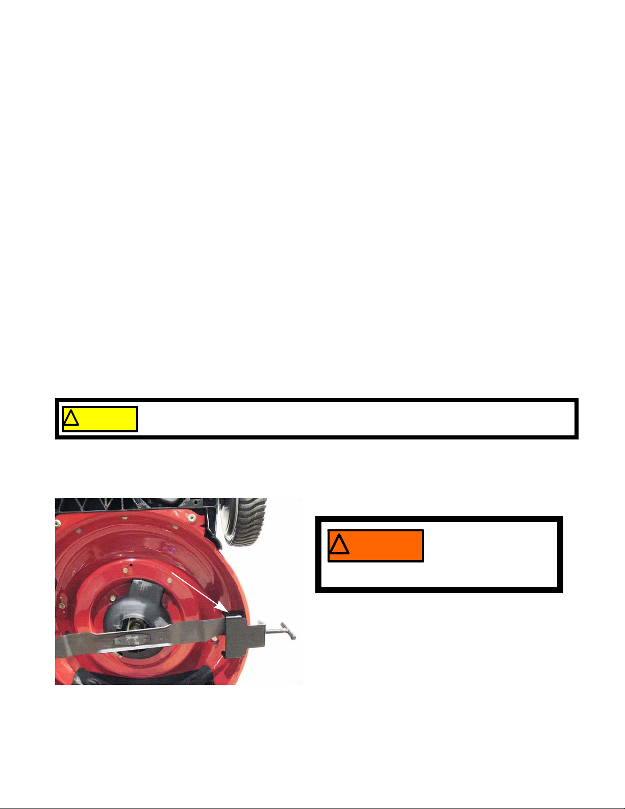
1. Tip the mower with the muffler side down, or tilt the
mower back on a work bench, with the front wheels
up. See Figure 2.1.
Disconnect and ground
the spark plug wire.
Figure 2.1
2. Block the blade from rotating using a block of wood
or a blade holder tool.
NOTE: MTD blade holding tool, part number 490-850-
0005, can be used block the blade. See Figure 2.1.
7
A and B series mowers
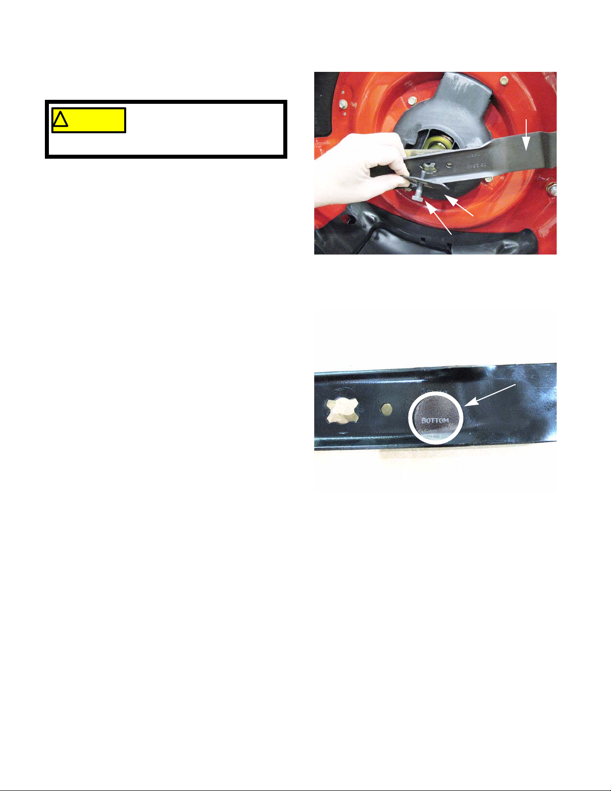
3. Remove the blade bolt and diamond-shaped
Belleville blade spring using a 5/8” wrench.
Use care around the blade
! CA UTION! CA UTION
cause injury.
4. Lift away the blade. See Figure 2.2.
5. Inspect the blade. If it is bent or worn beyond proper
sharpening, replace it with a new blade.
6. Sharpen and balance the blade if it is not badly
worn.
7. Check the blade adapter, crankshaft and hardware
for damage.
8. Install the blade with the blade adapter and
Belleville spring washer properly positioned. Tighten
the blade bolt to a torque of 38-50 ft.-lb. (51-68 Nm).
NOTE: OEM blades manufactured by MTD are
while removing or tightening the
bolt. The blade can spin and
stamped with the part number and the word
“BOTTOM”. The word bottom should face
the ground when the mower is in its normal
operating position. See Figure 2.3.
Blade
Belleville spring
Bolt
Figure 2.2
Bottom stamped in blade
Figure 2.3
8
 Loading...