

MSI Z370 GODLIKE GAMING User Manual
1
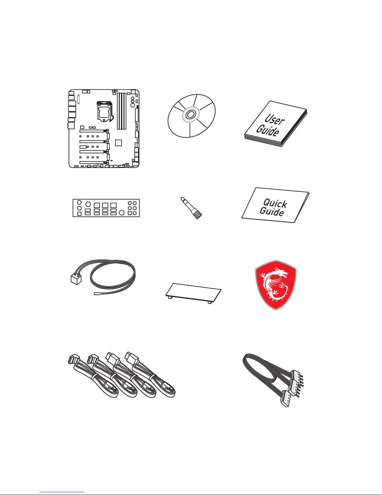
Unpacking
Unpacking
Thank you for buying the MSI® Z370 GODLIKE GAMING motherboard. Check to make
sure your motherboard box contains the following items. If something is missing,
contact your dealer as soon as possible.
SATA Cable x4
SLI Bridge
Connector
Thermistor
Cable x3
Drivers & Utilities
Disc
Motherboard User
Guide
I/O Shield
Motherboard
Case Badge
Quick Guide
6.3mm - 3.5mm
headphone Jack
1 to 2 RGB LED Extension
Y Cable 80cm x1
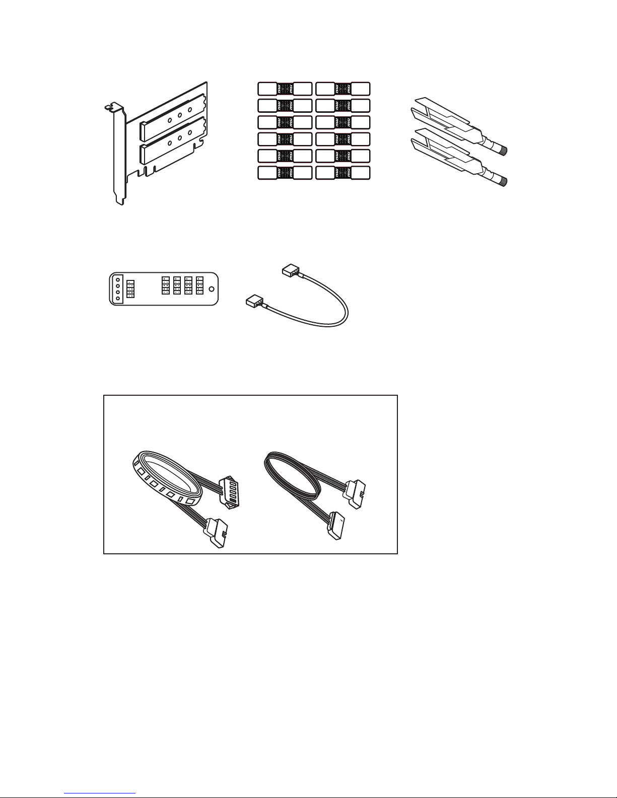
2
Unpacking
SATA Cable Labels
Antenna x2
C D 5V GND
Rainbow 5050 RGB LED strip set (5V)
M.2 Xpander-Z
USB Xpander
USB Xpander Cable

3
Safety Information
Safety Information
y The components included in this package are prone to damage from electrostatic
discharge (ESD). Please adhere to the following instructions to ensure successful
computer assembly.
y Ensure that all components are securely connected. Loose connections may cause
the computer to not recognize a component or fail to start.
y Hold the motherboard by the edges to avoid touching sensitive components.
y It is recommended to wear an electrostatic discharge (ESD) wrist strap when
handling the motherboard to prevent electrostatic damage. If an ESD wrist strap is
not available, discharge yourself of static electricity by touching another metal object
before handling the motherboard.
y Store the motherboard in an electrostatic shielding container or on an anti-static pad
whenever the motherboard is not installed.
y Before turning on the computer, ensure that there are no loose screws or metal
components on the motherboard or anywhere within the computer case.
y Do not boot the computer before installation is completed. This could cause
permanent damage to the components as well as injury to the user.
y If you need help during any installation step, please consult a certified computer
technician.
y Always turn off the power supply and unplug the power cord from the power outlet
before installing or removing any computer component.
y Keep this user guide for future reference.
y Keep this motherboard away from humidity.
y Make sure that your electrical outlet provides the same voltage as is indicated on the
PSU, before connecting the PSU to the electrical outlet.
y Place the power cord such a way that people can not step on it. Do not place anything
over the power cord.
y All cautions and warnings on the motherboard should be noted.
y If any of the following situations arises, get the motherboard checked by service
personnel:
Liquid has penetrated into the computer.
The motherboard has been exposed to moisture.
The motherboard does not work well or you can not get it work according to user
guide.
The motherboard has been dropped and damaged.
The motherboard has obvious sign of breakage.
y Do not leave this motherboard in an environment above 60°C (140°F), it may damage
the motherboard.
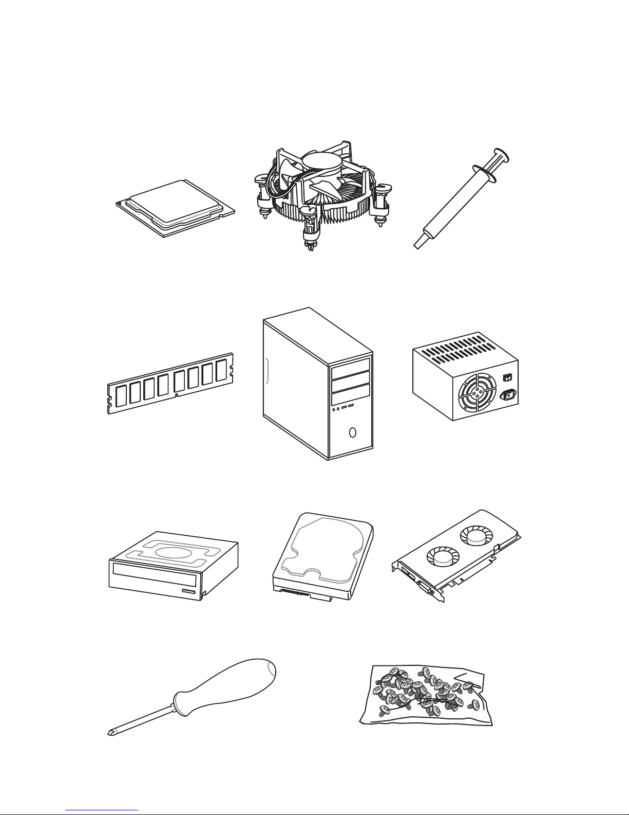
4
Quick Start
DDR4 Memory
Graphics Card
SATA Hard Disk Drive
SATA DVD Drive
A Package of Screws
Phillips Screwdriver
Chassis
Power Supply Unit
Thermal Paste
Quick Start
Preparing Tools and Components
Intel® LGA 1151 CPU
CPU Fan

5
Quick Start
http://youtu.be/bf5La099urI
Installing a Processor
1
2
3
6
4
5
7
8
9
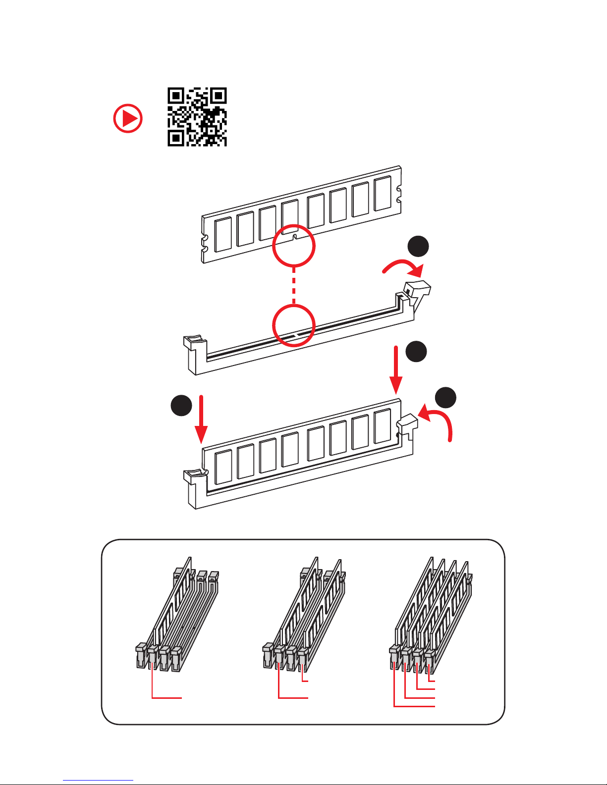
6
Quick Start
Installing DDR4 memory
http://youtu.be/T03aDrJPyQs
1
2
2
3
DIMMB2 DIMMB2
DIMMB1
DIMMA2 DIMMA2 DIMMA2
DIMMA1
7
Quick Start
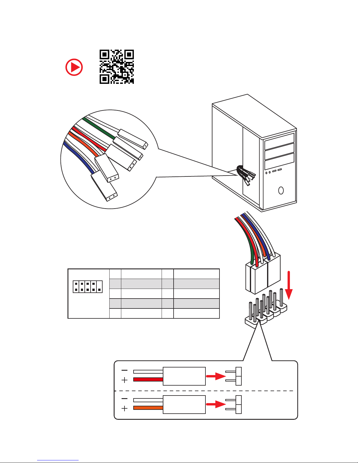
Connecting the Front Panel Header
http://youtu.be/DPELIdVNZUI
1
2 10
9
JFP1
1 HDD LED + 2 Power LED +
3 HDD LED - 4 Power LED -
5 Reset Switch 6 Power Switch
7 Reset Switch 8 Power Switch
9 Reserved 10 No Pin
RESET SW
POWER SW
POWER LED+
POWER LED-
HDD LED
HDD LED
RESET SW
JFP1
HDD LED
HDD LED HDD LED +
POWER LED POWER LED +
POWER LED
8
Quick Start
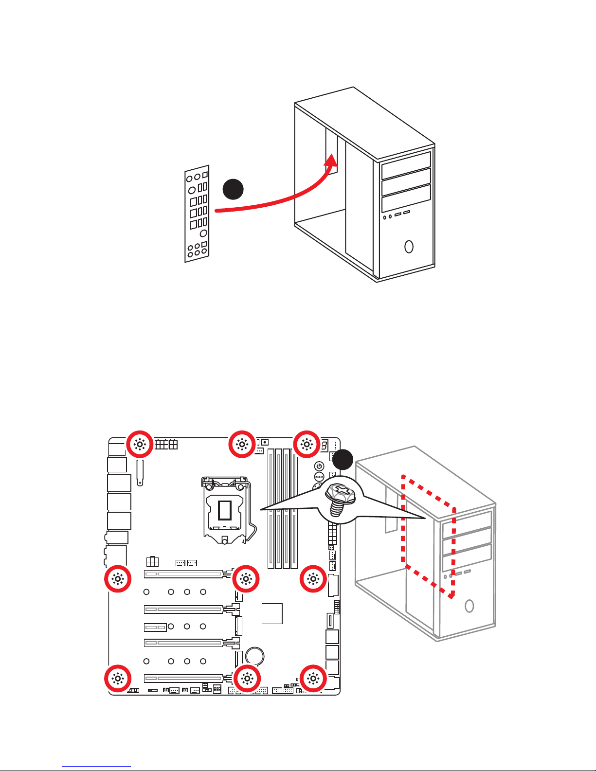
BAT1
Installing the Motherboard
1
2
9
Quick Start
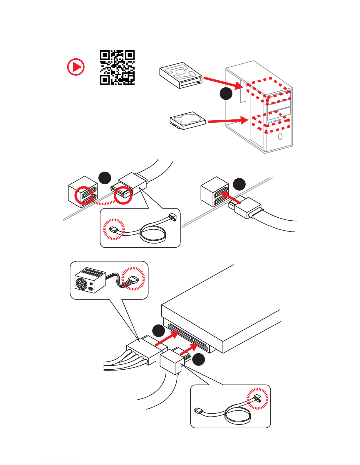
Installing SATA Drives
http://youtu.be/RZsMpqxythc
1
2
3
4
5
10
Quick Start
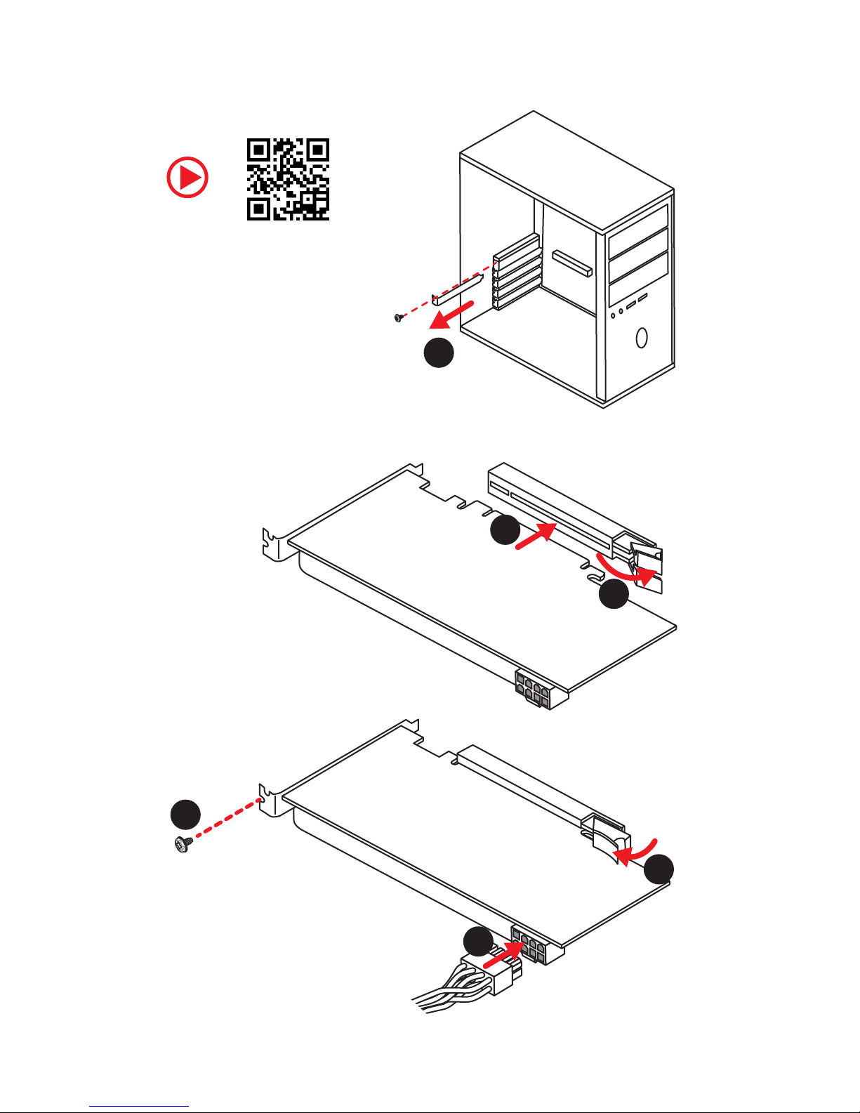
1
Installing a Graphics Card
http://youtu.be/mG0GZpr9w_A
2
3
4
5
6
11
Quick Start
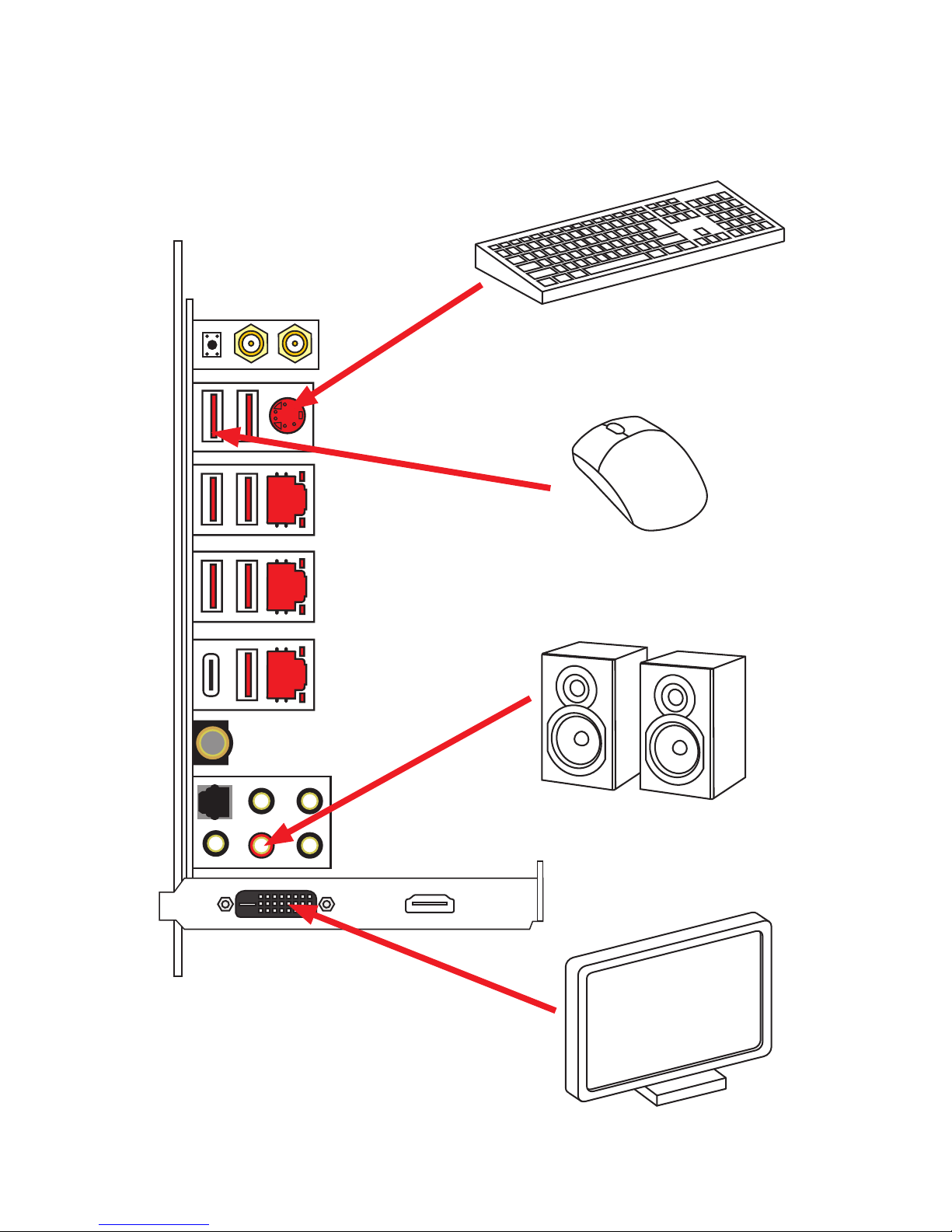
Connecting Peripheral Devices
12
Quick Start
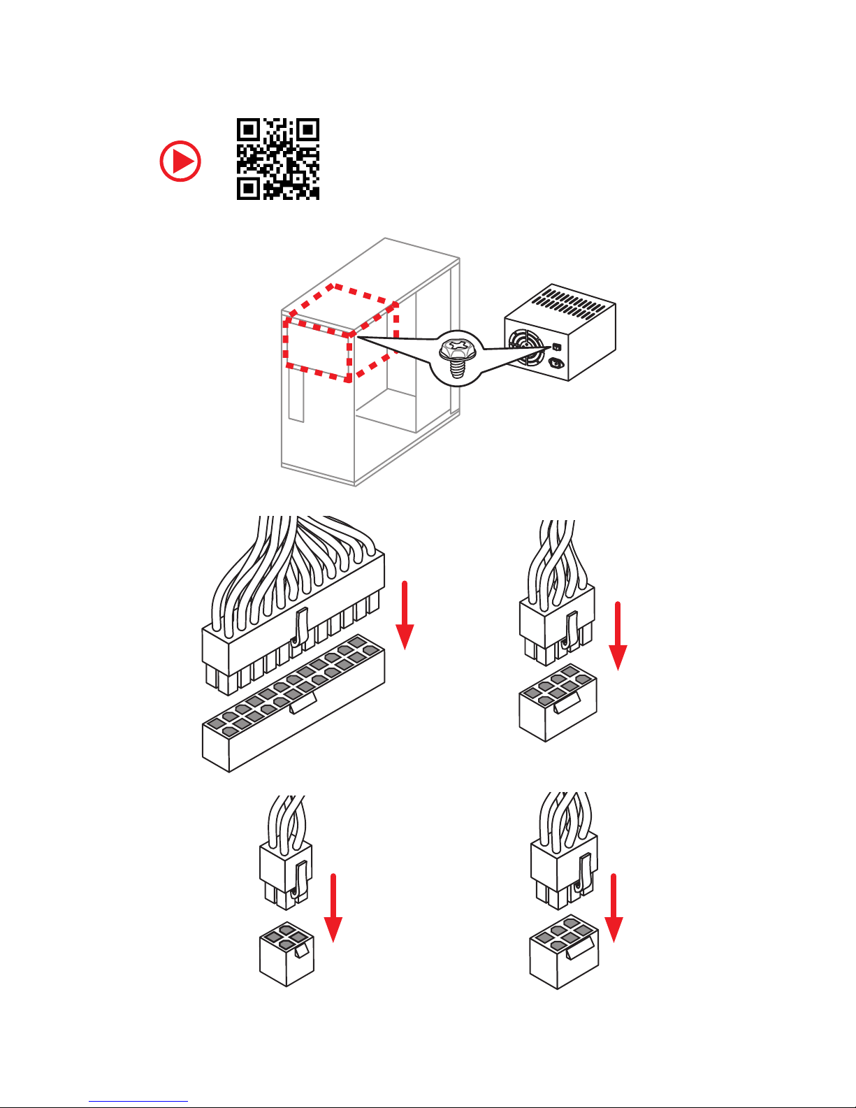
Connecting the Power Connectors
http://youtu.be/gkDYyR_83I4
ATX_PWR1
CPU_PWR1
CPU_PWR2
PCIE_PWR1
13
Quick Start
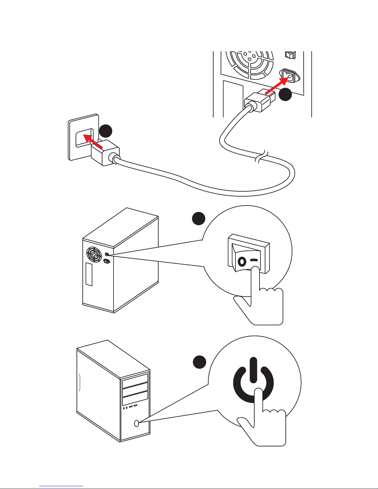
Power On
1
4
2
3

14
Contents
Contents
Unpacking .............................................................................................................. 1
Safety Information ................................................................................................. 3
Quick Start ............................................................................................................. 4
Preparing Tools and Components .......................................................................... 4
Installing a Processor ............................................................................................. 5
Installing DDR4 memory ........................................................................................ 6
Connecting the Front Panel Header ....................................................................... 7
Installing the Motherboard ..................................................................................... 8
Installing SATA Drives............................................................................................. 9
Installing a Graphics Card .................................................................................... 10
Connecting Peripheral Devices ............................................................................ 11
Connecting the Power Connectors ....................................................................... 12
Power On............................................................................................................... 13
Specifications ....................................................................................................... 17
Block Diagram .................................................................................................... 24
Rear I/O Panel ..................................................................................................... 25
LAN Port LED Status Table................................................................................... 25
Audio Ports Configuration .................................................................................... 25
Realtek HD Audio Manager .................................................................................. 26
Installing Antennas ............................................................................................... 28
FLASHB1: BIOS FLASHBACK+ Button ................................................................. 28
Overview of Components .................................................................................... 29
CPU Socket ........................................................................................................... 31
DIMM Slots ............................................................................................................ 32
PCI_E1~5: PCIe Expansion Slots .......................................................................... 33
PEGSW1: PCIe CeaseFire Switch ......................................................................... 34
U2_1: U.2 Connector ............................................................................................. 36
M2_1~3: M.2 Slots (Key M) ................................................................................... 37
Installing the M.2 Xpander-Z ............................................................................... 38
SATA1~6: SATA 6Gb/s Connectors ....................................................................... 39
JFP1, JFP2: Front Panel Connectors ................................................................... 41
OC1: GAME BOOST Knob ..................................................................................... 42
JSLOW1: Slow Mode Booting Jumper .................................................................. 43
CPU_PWR1~2, ATX_PWR1, PCIE_PWR1: Power Connectors .............................. 44
JUSB3~5: USB 2.0 Connectors ............................................................................. 45
JUSB2: USB 3.1 Gen2 Type-C Connector ............................................................. 46
JUSB1, JUSB6: USB 3.1 Gen1 Connectors........................................................... 46

15
Contents
T_SEN1~3: Thermal Sensor Connectors ............................................................. 47
CPU_FAN1, PUMP_FAN1, SYS_FAN1~8: Fan Connectors ................................... 48
JAUD1: Front Audio Connector ............................................................................ 49
JCI1: Chassis Intrusion Connector ....................................................................... 49
JTPM1: TPM Module Connector ........................................................................... 50
JBAT1: Clear CMOS (Reset BIOS) Jumper ........................................................... 50
BIOS_SW1: Multi-BIOS Switch ............................................................................. 51
POWER1, RESET1: Power Button, Reset Button ................................................. 52
OC_FS1: OC Force Enter BIOS Button .................................................................. 52
OC_RT2: OC Retry Button ..................................................................................... 52
JRGB1, JRAINBOW1: RGB LED connectors ......................................................... 53
Onboard LEDs ...................................................................................................... 54
EZ Debug LED ....................................................................................................... 54
PCIe x16 slot & M.2 slot LEDs .............................................................................. 54
DIMM LEDs ........................................................................................................... 54
XMP LED ............................................................................................................... 54
Fan LEDs ............................................................................................................... 55
Fan Speed Indicators ............................................................................................ 55
Multi-BIOS LEDs ................................................................................................... 55
GAME BOOST LEDs .............................................................................................. 55
Debug Code LED ................................................................................................... 56
Hexadecimal Character Table .............................................................................. 56
Boot Phases .......................................................................................................... 56
Debug Code LED Table ......................................................................................... 56
ACPI States Codes ................................................................................................ 58
CPU Temperature ................................................................................................. 58
BIOS Setup ........................................................................................................... 59
Entering BIOS Setup ............................................................................................. 59
Resetting BIOS ...................................................................................................... 60
Updating BIOS ....................................................................................................... 60
EZ Mode ................................................................................................................ 62
Advanced Mode .................................................................................................... 64
SETTINGS .............................................................................................................. 65
Advanced ............................................................................................................... 65
Boot ....................................................................................................................... 70
Security ................................................................................................................. 71
Save & Exit ............................................................................................................ 72
OC .......................................................................................................................... 73
M-FLASH .............................................................................................................. 83
OC PROFILE .......................................................................................................... 84

16
Contents
HARDWARE MONITOR .......................................................................................... 85
Software Description ........................................................................................... 86
Installing Windows® 10 ......................................................................................... 86
Installing Drivers .................................................................................................. 86
Installing Utilities ................................................................................................. 86
APP MANAGER ..................................................................................................... 87
LIVE UPDATE 6 ...................................................................................................... 88
COMMAND CENTER ............................................................................................. 90
GAMING APP ......................................................................................................... 94
X-BOOST ............................................................................................................... 99
MYSTICLIGHT ...................................................................................................... 101
MSI SMART TOOL ............................................................................................... 103
RAMDISK............................................................................................................. 105
Killer Control Center .......................................................................................... 106
DRAGON EYE ...................................................................................................... 107
Nahimic 2 ............................................................................................................ 108
XSplit Gamecaster V2 ......................................................................................... 112
SteelSeries Engine 3 .......................................................................................... 116
Intel
®
Extreme Tuning Utility .............................................................................. 118
CPU-Z.................................................................................................................. 119
TriDef VR ............................................................................................................. 120
TriDef SmartCam ................................................................................................ 123
RAID Configuration ............................................................................................ 124
Using Intel® Rapid Storage Technology Option ROM ......................................... 124
Degraded RAID Array ......................................................................................... 127
M.2 PCIe SSD RAID ............................................................................................. 129
Intel® Optane™ Memory Configuration ............................................................ 132
System Requirements ....................................................................................... 132
Installing the Intel
®
Optane™ memory .............................................................. 132
Removing the Intel
®
Optane™ memory ............................................................. 134
Troubleshooting .................................................................................................. 135
Troubleshooting ................................................................................................ 136
Regulatory Notices ............................................................................................ 137
17
Specifications
Specifications
CPU
Supports 8th Generation Intel
®
Core™ Processors, and Intel®
Pentium
®
and Celeron® Processors for Socket LGA1151
Chipset Intel
®
Z370 Chipset
Memory
y 4x DDR4 memory slots, support up to 64GB
y Supports DDR4 4133+(OC)/ 4000(OC)/ 3866(OC)/ 3733(OC)/
3600(OC)/ 3466(OC)/ 3400(OC)/ 3333(OC)/ 3300(OC)/
3200(OC)/ 3000(OC) /2800(OC)/ 2667/ 2400/ 2133 MHz*
y Dual channel memory architecture
y Supports Intel
®
Extreme Memory Profile (XMP)
* For the latest information about memory, please visit http://www.msi.com
Expansion Slots
y 4x PCIe 3.0 x16 slots*
y 1x PCIe 3.0 x1 slot
* Please refer to page 33 for details.
Multi-GPU
y Supports 2-Way NVIDIA
®
SLI™ Technology
y Supports 4-Way AMD
®
CrossFire™ Technology
Storage
Intel
®
Z370 Chipset
y 6x SATA 6Gb/s ports*
y 3x M.2 slots (Key M)*
Supports up to PCIe 3.0 x4 and SATA 6Gb/s
M2_1, M2_3 slots support 2242/ 2260 /2280/ 22110
storage devices
M2_2 slot supports 2242/ 2260 /2280 storage devices
Intel
®
Optane™ Memory Ready**
y 1x U.2 port
Supports PCIe 3.0 x4 NVMe storage
* M.2 slots, U.2 port and SATA ports share the bandwidth. Please refer to page
39 for details.
** Please refer to page 132 for Intel
®
Optane™ Memory Configuration.
Continued on next page
18
Specifications
Continued from previous page
RAID
Intel
®
Z370 Chipset
y Supports RAID 0, RAID1, RAID 5 and RAID 10 for SATA
storage devices
y Supports RAID 0, RAID 1 and RAID5 for M.2 PCIe storage
devices*
* M.2 PCIe RAID volume can be created with M.2 GENIE. Please refer to page 129
for details.
LAN y 3x Killer® E2500 Gigabit LAN controller
Wirsless LAN &
Bluetooth
®
Killer® 1535
y The Wireless module is pre-install in the M2_4 (Key-E) slot.
y Supports Wi-Fi 2x2 802.11 AC
y Supports Bluetooth
®
4.1, 3.0+HS
USB
y ASMedia
®
ASM3142 Chipset
3x USB 3.1 Gen2 (SuperSpeed USB 10Gbps) ports
(1 Type-A port and 1 Type-C port on the back panel,
1 Type-C port available through the internal USB
connector)
y ASMedia
®
ASM1074 Chipset
4x USB 3.1 Gen1 (SuperSpeed USB) ports on the back
panel
y Intel
®
Z370 Chipset
6x USB 3.1 Gen1 (SuperSpeed USB) ports (2 Type-A
ports on the back panel, 4 ports available through the
internal USB connectors)
6x USB 2.0 (High-speed USB) ports available through
the internal USB connectors
Audio
y Realtek
®
ALC1220 Codec
7.1-Channel High Definition Audio
Supports S/PDIF output
y ESS
®
E9018 Codec
Supports 6.3mm Gold-plated stereo headphone out
Continued on next page

19
Specifications
Continued from previous page
Back Panel
Connectors
y 1x Clear CMOS button
y 2x Wi-Fi Antenna connectors
y 1x PS/2 keyboard/ mouse combo port
y 6x USB 3.1 Gen1 Type-A ports
y 3x LAN (RJ45) ports
y 1x USB 3.1 Gen2 Type-A port
y 1x USB 3.1 Gen2 Type-C port
y 1x 6.3mm Gold-plated stereo headphone jack
y 5x OFC audio jacks
y 1x Optical S/PDIF OUT connector
Internal Connectors
y 1x 24-pin ATX main power connector
y 1x 8-pin ATX 12V power connector
y 1x 4-pin ATX 12V power connector
y 1x 6-pin ATX PCIe power connector
y 6x SATA 6Gb/s connectors
y 4x M.2 slots (M Key x3 ,E Key x1)
y 1x U.2 port
y 1x USB 3.1 Gen2 Type-C port
y 2x USB 3.1 Gen1 connectors (supports additional 4 USB 3.1
Gen1 ports)
y 3x USB 2.0 connectors (supports additional 6 USB 2.0
ports)
y 1x 4-pin CPU fan connector
y 1x 4-pin Water Pump connector
y 8x 4-pin system fan connectors
y 2x Front panel connectors
y 1x Front panel audio connector
y 1x TPM module connector
y 1x Chassis Intrusion connector
y 3x 2-pin Thermal Sensors connectors
y 1x 5050 RGB LED 12V connector (JRGB1)
y 1x Rainbow 5050 RGB LED 5V connector (JRAINBOW1)
Continued on next page
20
Specifications
Continued from previous page
Internal Buttons
y 1x GAME BOOST knob
y 1x Power button
y 1x Reset button
y 1x OC retry button
y 1x OC force enter BIOS button
y 1x BIOS FLASHBACK+ button
Switches
y 1x Multi-BIOS switch
y 1x PCIe CeaseFire switch
Jumper
y 1x Clear CMOS jumper
y 1x Slow mode jumper
Debug LED y 1x 2-Digit Debug Code LED
I/O Controller NUVOTON NCT6795 Controller Chip
Hardware Monitor
y CPU/System temperature detection
y CPU/System fan speed detection
y CPU/System fan speed control
Form Factor
y E-ATX Form Factor
y 12 in. x 10.7 in. (30.5 cm x 27.2 cm)
BIOS Features
y Dual BIOS
y 2x 128 Mb flash
y UEFI AMI BIOS
y ACPI 6.0, SM BIOS 3.0
y Multi-language
Continued on next page

21
Specifications
Continued from previous page
Software
y Drivers
y APP MANAGER
y SUPER CHARGER
y COMMAND CENTER
y LIVE UPDATE 6
y SMART TOOL
y RAMDISK
y DPC LATENCY TUNER
y FAST BOOT
y X-BOOST
y DRAGON EYE
y GAMING APP
y MYSTIC LIGHT
y Nahimic Audio
y Killer Control Center
y XSplit Gamecaster V2
y TriDef
®
VR & SmartCam
y SteelSeries Engine 3
y WTFast*
y CPU-Z MSI GAMING
y Intel Extreme Tuning Utility
y Norton™ Internet Security Solution
y Google Chrome™ ,Google Toolbar, Google Drive
* This offer is valid for a limited period only, for more information please visit
www.msi.com
Continued on next page

22
Specifications
Continued from previous page
Special Features
y Audio
Xtreme Audio DAC
Nahimic 2
y Network
Killer xTend
GAMING LAN with Killer LAN Manage
Killer WiFi
y Storage
Turbo U.2
Triple Turbo M.2
y Fan
Pump Fan
Smart Fan Control
y LED
Mystic Light
Mystic Light Extension (RGB)
Mystic Light Extension (RAINBOW)
Mystic light SYNC
EZ DEBUG LED
y Protection
DDR4 Steel Armor
M.2 Shield
PCI-E Steel Armor
U.2 Steel Armor
Continued on next page

23
Specifications
Continued from previous page
Special Features
y Performance
Multi GPU – SLI Technology
Multi GPU – CrossFire Technology
DDR4 Boost
GAME Boost(go to 11)
OC Engine(Clock gen)
USB with Type A+C
Lightning USB
Front Lightning USB
y Stability
Military Class 5
y VR
VR Ready
y Gamer Experience
GAMING HOTKEY
GAMING MOUSE Control
y BIOS
Click BIOS 5
BIOS FLASHBACK+
Dual BIOS
y Certification
Quadro SLI Ready
Quadro Ready
SteelSeries Certified
24
Block Diagram
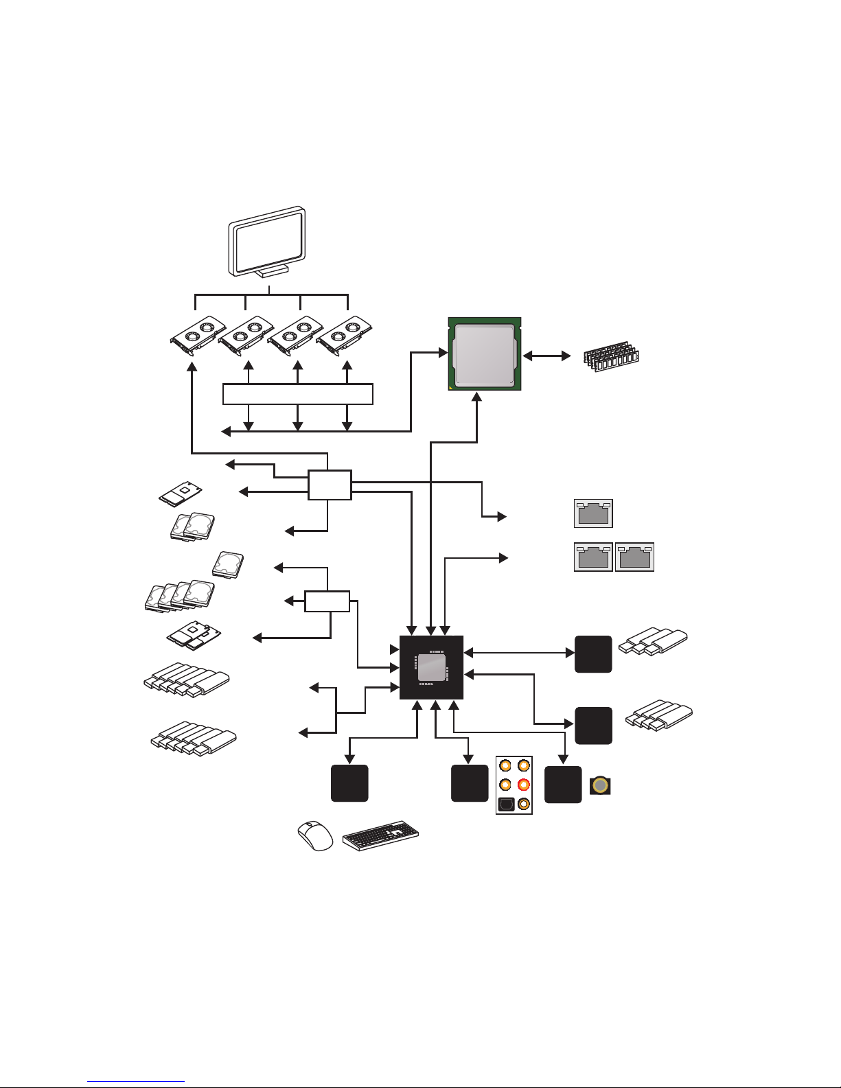
Block Diagram
x2
(Rear + Front)
4x USB 3.1 Gen1
2 Channel DDR4 Memory
3x USB 3.1 Gen2
PCIE Bus
PCIE Bus
PCIE Bus
DMI 3.0
PCI Express Bus
PCH
Processor
NV6795
Super I/O
Realtek
ALC1220
ASMEDIA
ASM1074
6x USB 3.1 Gen1
6x USB 2.0
ESS
E9018
1x U.2
PCIe x1 slot
ASMEDIA
ASM3142
Audio Jacks
P/S2 Mouse / Keyboard
2x M.2
Switch
1x M.2
Switch
2x Killer 2500
1x Killer 2500
Switch
4x SATA 6Gb/s
2x SATA 6Gb/s
25
Rear I/O Panel
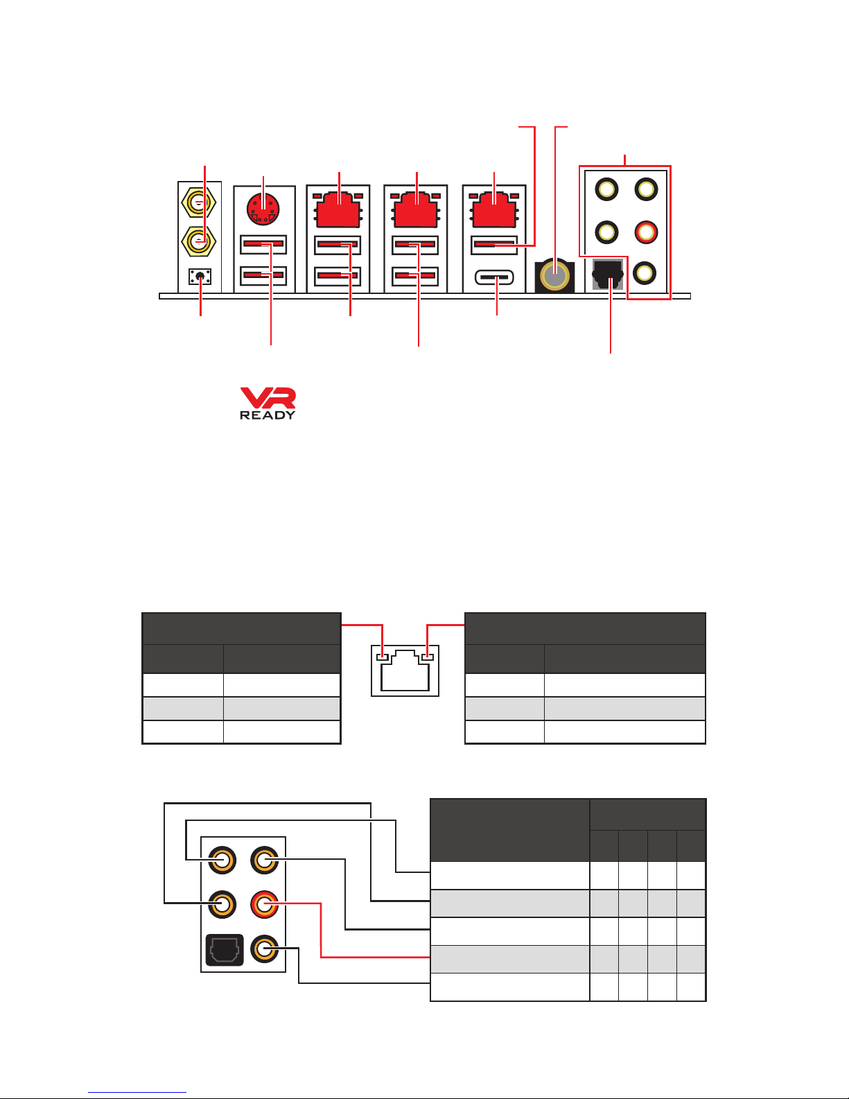
Rear I/O Panel
PS/2
Clear CMOS
Wi-Fi Antenna
connectors
LAN1
(WAN)
LAN2 LAN3*
Audio Ports
6.3mm headphone
Optical S/PDIF-Out
USB 3.1 Gen1
USB 3.1 Gen2 Type-A
USB 3.1 Gen2 Type-C
Link/ Activity LED
Status Description
Off No link
Yellow Linked
Blinking Data activity
Speed LED
Status Description
Off 10 Mbps connection
Green 100 Mbps connection
Orange 1 Gbps connection
LAN Port LED Status Table
Audio Ports Configuration
Audio Ports
Channel
2 4 6 8
Center/ Subwoofer Out ● ●
Rear Speaker Out ● ● ●
Line-In/ Side Speaker Out ●
Line-Out/ Front Speaker Out ● ● ● ●
Mic In
(●: connected, Blank: empty)
y Clear CMOS button - Power off your computer. Press and hold the Clear CMOS
button for about 5-10 seconds to reset BIOS to default values.
y BIOS FLASHBACK+ port - Please refer to page 61 for Updating BIOS with BIOS
FLASHBACK+.
y 6.3mm headphone port - This port is used for connecting the headphone.
* LAN3 will be unavailable when installing the PCIe device in the PCI_E5 slot.
USB 3.1 Gen1/
BIOS FLASHBACK+
port
USB 3.1 Gen1
26
Rear I/O Panel
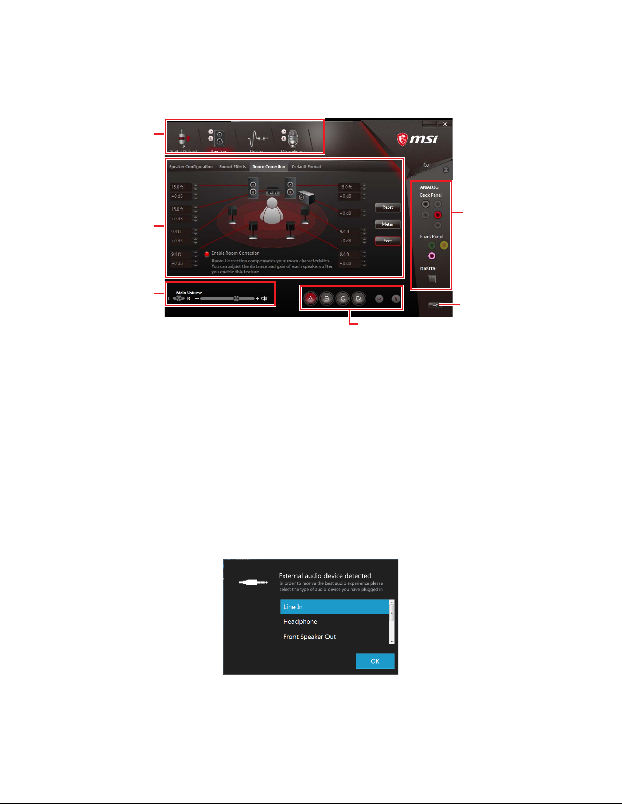
Realtek HD Audio Manager
After installing the Realtek HD Audio driver, the Realtek HD Audio Manager icon will
appear in the system tray. Double click on the icon to launch.
y Device Selection - allows you to select a audio output source to change the related
options. The check sign indicates the devices as default.
y Application Enhancement - the array of options will provide you a complete guidance
of anticipated sound effect for both output and input device.
y Main Volume - controls the volume or balance the right/left side of the speakers that
you plugged in front or rear panel by adjust the bar.
y Profiles - toggles between profiles.
y Jack Status - depicts all render and capture devices currently connected with your
computer.
y Connector Settings - configures the connection settings.
Auto popup dialog
When you plug into a device at an audio jack, a dialogue window will pop up asking you
which device is current connected.
Each jack corresponds to its default setting as shown on the next page.
Jack Status
Device
Selection
Connector
Settings
Profiles
Main Volume
Application
Enhancement
27
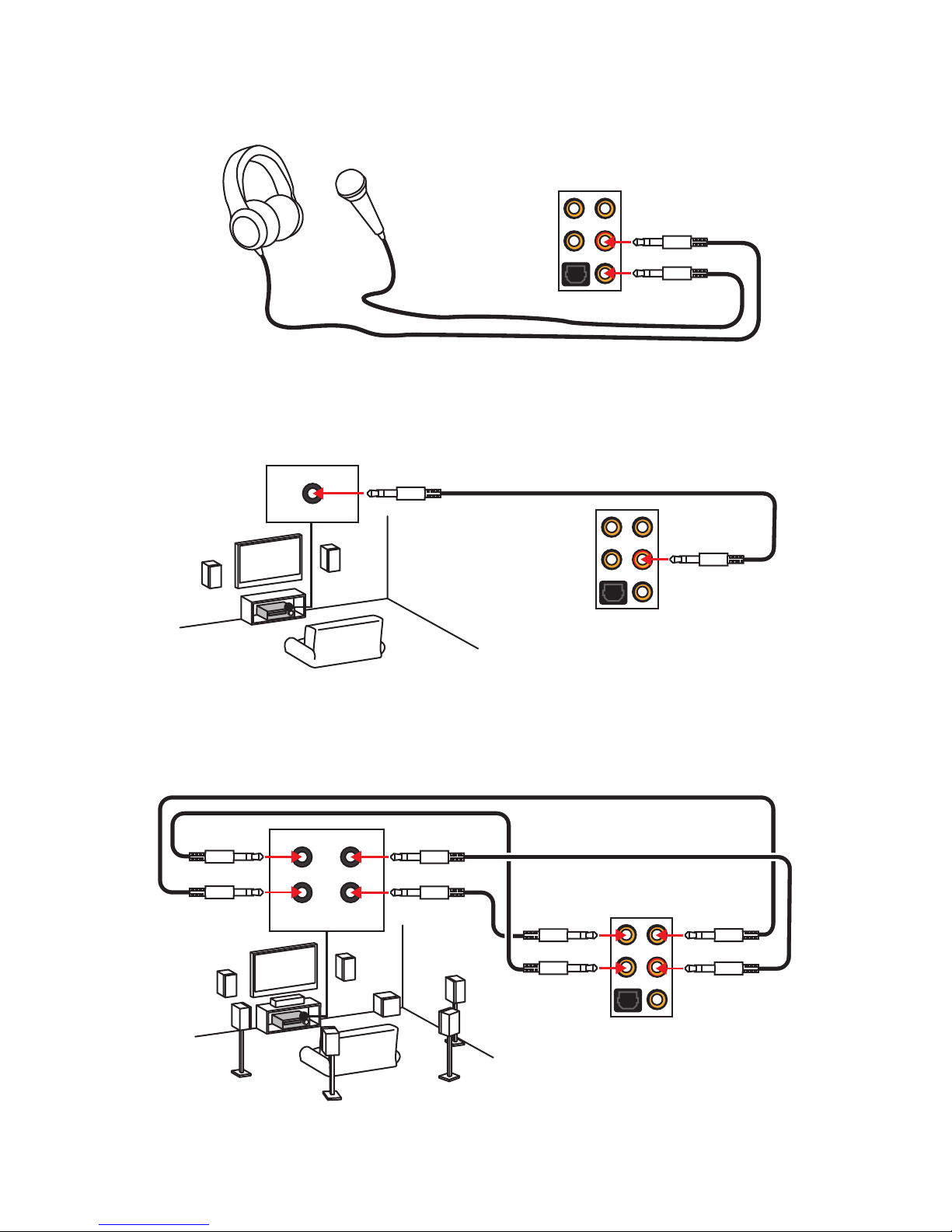
Rear I/O Panel
AUDIO INPUT
Rear Front
Side Center/
Subwoofer
Audio jacks to headphone and microphone diagram
Audio jacks to stereo speakers diagram
Audio jacks to 7.1-channel speakers diagram
AUDIO INPUT

28
Rear I/O Panel
Installing Antennas
1. Screw one antenna tight to the WiFi antenna connector as shown.
2. Adjust the orientations of antennas for better reception.
3. Follow the step1 & 2 to install another antenna.
1
2
FLASHB1: BIOS FLASHBACK+ Button
This button is used to activate the BIOS FLASHBACK+ function. Please refer to page 61
for Updating BIOS with BIOS FLASHBACK+.
29
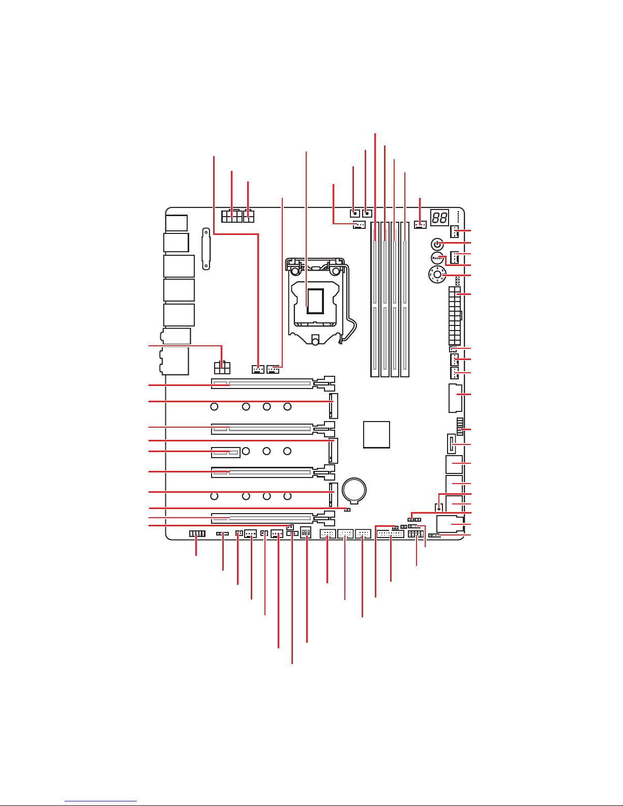
Overview of Components
Overview of Components
DIMMA1
CPU_PWR2
CPU_PWR1
CPU Socket
CPU_FAN1
OC_FS1
OC_RT2
SYS_FAN1
SYS_FAN2
JFP1
POWER1
RESET1
OC1
PUMP_FAN1
SYS_FAN3
SYS_FAN4
T_SEN1
JUSB2
JTPM1
JUSB1
JFP2
JUSB6
JCI1
JUSB5
JUSB4
JUSB3
PCIE_PWR1
PCI_E1
M2_1
PCI_E2
M2_2
PCI_E3
M2_3
JBAT1
PCI_E4
PCI_E5
JPWRLED1
BIOS_SW1
SYS_FAN7
T_SEN3
SYS_FAN8
T_SEN2
JRGB1
JAUD1
PEGSW1
SATA▼1▲2
SATA▼3▲4
SATA▼5▲6
U2_1
JSLOW1
JRAINBOW1
FLASHB1
ATX_PWR1
DIMMA2
DIMMB1
DIMMB2
BAT1
SYS_FAN5
SYS_FAN6
30
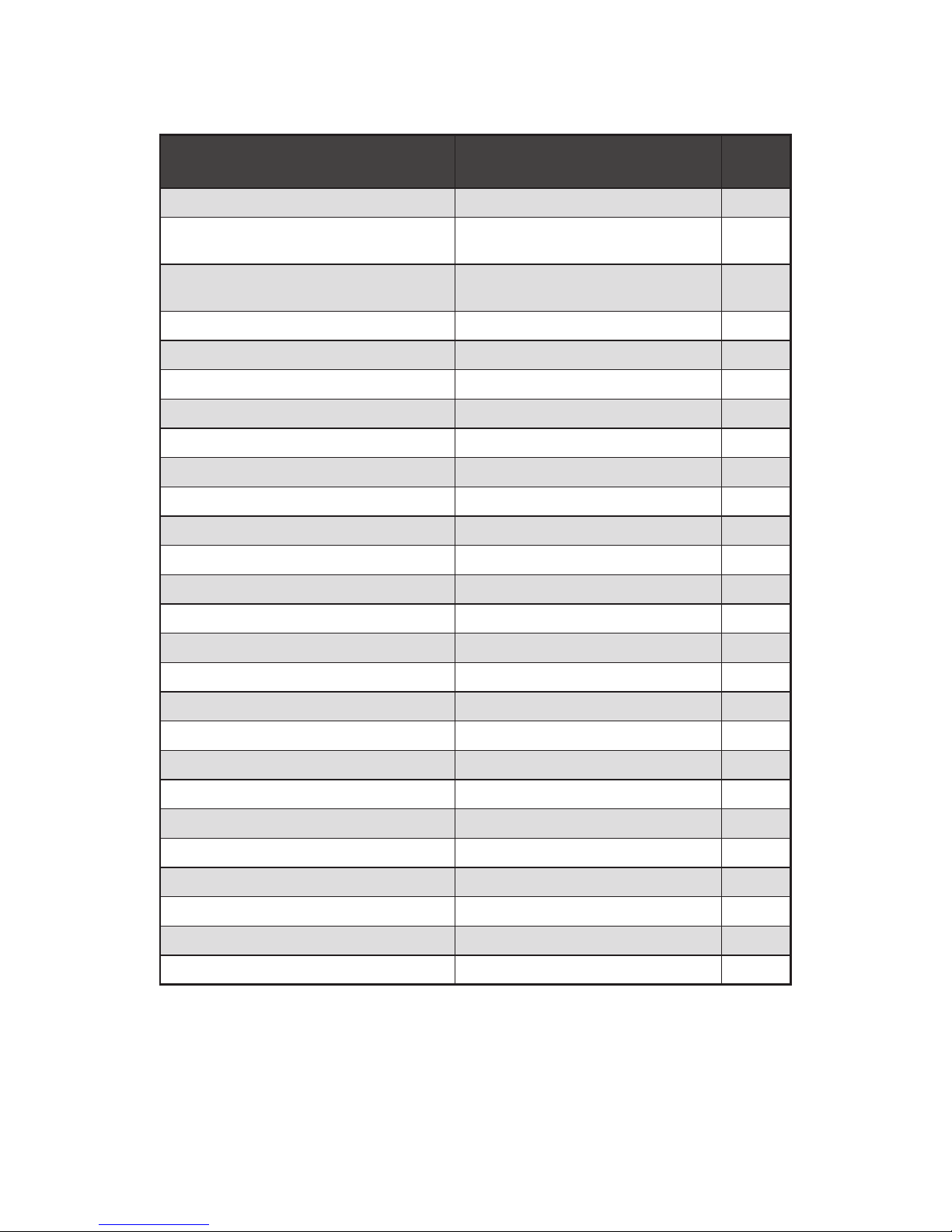
Overview of Components
Component Contents
Port Name Port Type Page
BIOS_SW1 Multi-BIOS Switch 51
CPU_FAN1, PUMP_FAN1,
SYS_FAN1~8
Fan Connectors 48
CPU_PWR1~2, ATX_PWR1,
PCIE_PWR1
Power Connectors 44
CPU Socket LGA1151 CPU Socket 31
DIMMA1/A2/B1/B2 DIMM Slots 32
FLASHB1 BIOS FLASHBACK+ Button 28
JAUD1 Front Audio Connector 49
JBAT1 Clear CMOS (Reset BIOS) Jumper 50
JCI1 Chassis Intrusion Connector 49
JFP1, JFP2 Front Panel Connectors 41
JRGB1, JRAINBOW1 RGB LED connectors 53
JSLOW1 Slow Mode Booting Jumper 43
JTPM1 TPM Module Connector 50
JUSB1, JUSB6 USB 3.1 Gen1 Connectors 46
JUSB2 USB 3.1 Gen2 Type-C Connector 46
JUSB3~5 USB 2.0 Connectors 45
M2_1~3 M.2 Slots (Key M) 37
OC1 GAME BOOST Knob 42
OC_FS1 OC Force Enter BIOS Button 52
OC_RT2 OC Retry Button 52
PCI_E1~5 PCIe Expansion Slots 33
PEGSW1 PCIe CeaseFire Switch 34
POWER1, RESET1 Power Button, Reset Button 52
SATA1~6 SATA 6Gb/s Connectors 39
T_SEN1~3 Thermal Sensor Connectors 47
U2_1 U.2 Connector 36
 Loading...