

Page 1
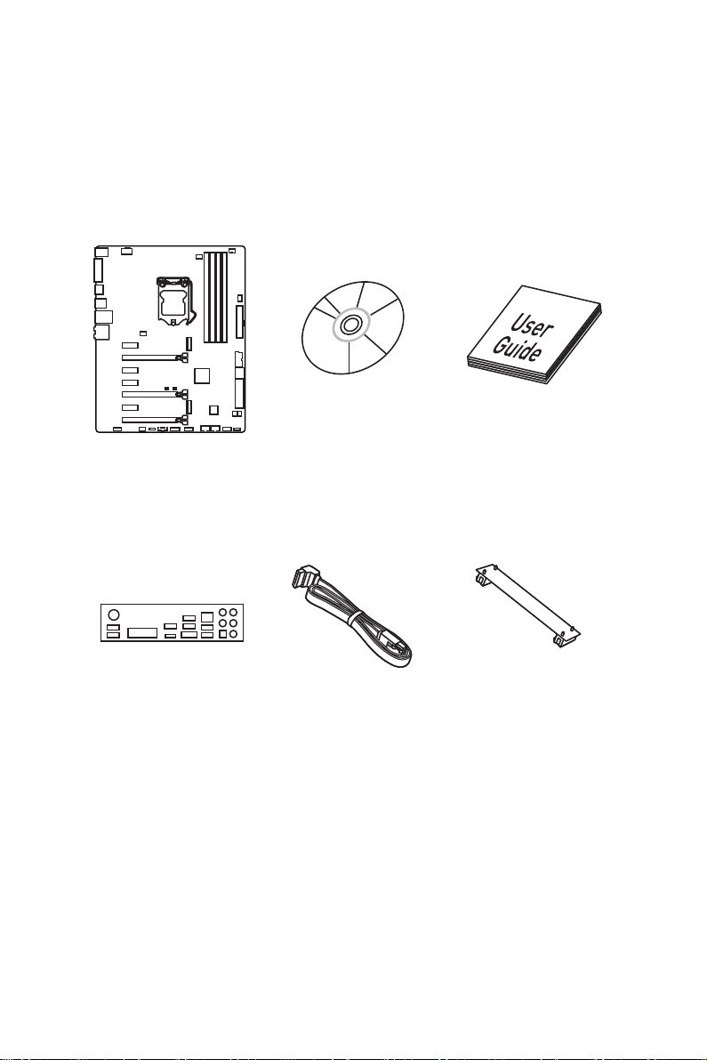
Unpacking
Thank you for buying the MSI® Z170A GAMING M5 motherboard. Check to make sure
your motherboard box contains the following items. If something is missing, contact
your dealer as soon as possible.
Motherboard
I/O Shield
Drivers & Utilities
Disc
SATA Cable
Motherboard User
Guide
SLI Bridge
Connector
Unpacking
1
Page 2

Safety Information
● The components included in this package are prone to damage from electrostatic
discharge (ESD). Please adhere to the following instructions to ensure successful
computer assembly.
● Ensure that all components are securely connected. Loose connections may cause
the computer to not recognize a component or fail to start.
● Hold the motherboard by the edges to avoid touching sensitive components.
● It is recommended to wear an electrostatic discharge (ESD) wrist strap when
handling the motherboard to prevent electrostatic damage. If an ESD wrist strap is
not available, discharge yourself of static electricity by touching another metal object
before handling the motherboard.
● Store the motherboard in an electrostatic shielding container or on an anti-static pad
whenever the motherboard is not installed.
● Before turning on the computer, ensure that there are no loose screws or metal
components on the motherboard or anywhere within the computer case.
● Do not boot the computer before installation is completed. This could cause
permanent damage to the components as well as injury to the user.
● If you need help during any installation step, please consult a certified computer
technician.
● Always turn off the power supply and unplug the power cord from the power outlet
before installing or removing any computer component.
● Keep this user guide for future reference.
● Keep this motherboard away from humidity.
● Make sure that your electrical outlet provides the same voltage as is indicated on
the PSU, before connecting the PSU to the electrical outlet.
● Place the power cord such a way that people can not step on it. Do not place
anything over the power cord.
● All cautions and warnings on the motherboard should be noted.
● If any of the following situations arises, get the motherboard checked by service
personnel:
▶ Liquid has penetrated into the computer.
▶ The motherboard has been exposed to moisture.
▶ The motherboard does not work well or you can not get it work according to user
guide.
▶ The motherboard has been dropped and damaged.
▶ The motherboard has obvious sign of breakage.
● Do not leave this motherboard in an environment above 60°C (140°F), it may
damage the motherboard.
Safety Information
2
Page 3
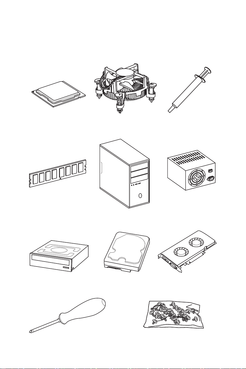
Quick Start
Preparing Tools and Components
Intel® LGA 1151 CPU
DDR4 Memory
SATA DVD Drive
CPU Fan Thermal Paste
Chassis
SATA Hard Disk Drive
Power Supply Unit
Graphics Card
Phillips Screwdriver
A Package of Screws
Quick Start
3
Page 4
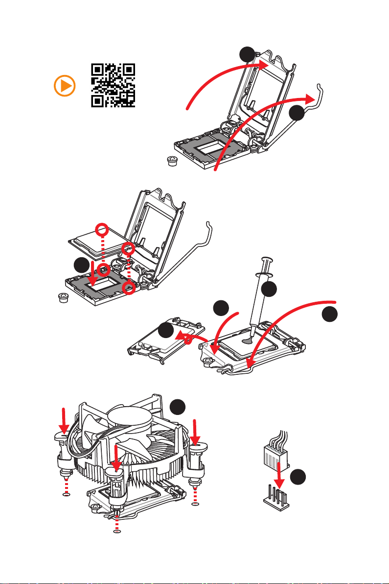
Installing a Processor
2
http://youtu.be/bf5La099urI
3
1
7
4
5
6
Quick Start
4
8
9
Page 5
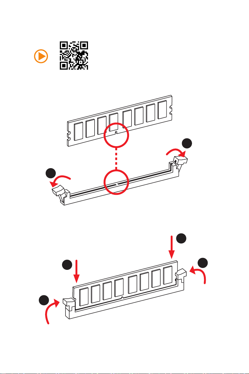
Installing DDR4 memory
http://youtu.be/T03aDrJPyQs
1
1
2
2
3
3
Quick Start
5
Page 6
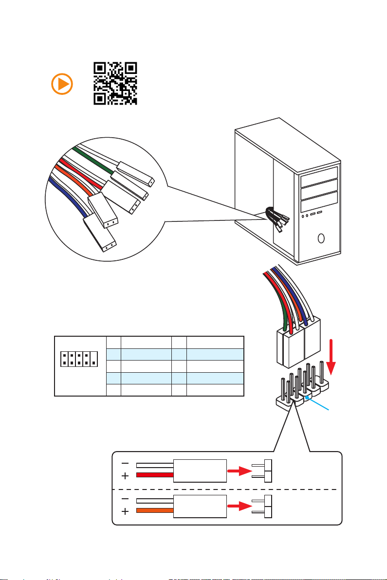
Connecting the Front Panel Header
RESET SW
POWER SW
POWER LED+
POWER LED-
HDD LED
http://youtu.be/DPELIdVNZUI
Quick Start
6
2 10
1
JFP1
1 HDD LED + 2 Power LED +
3 HDD LED - 4 Power LED -
5 Reset Switch 6 Power Switch
9
7 Reset Switch 8 Power Switch
9 Reserved 10 No Pin
HDD LED
POWER LED
RESET SW
HDD LED
JFP1
HDD LED HDD LED +
POWER LED POWER LED +
Page 7
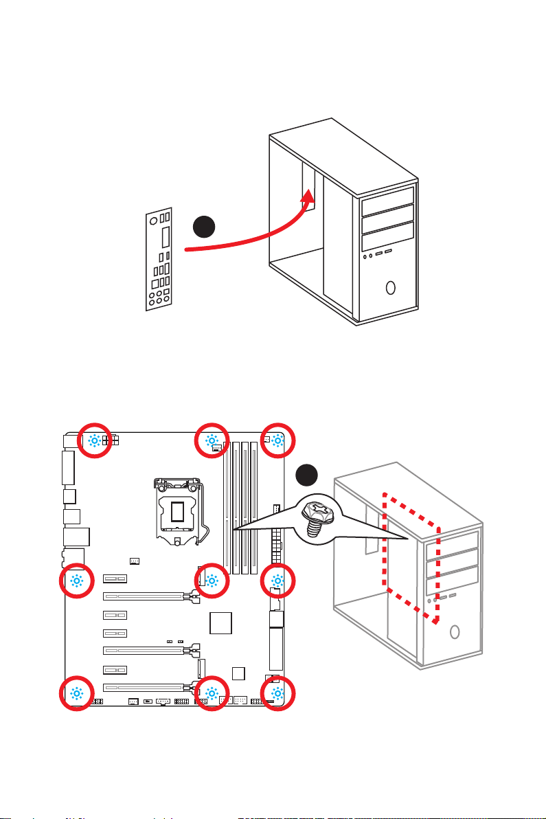
Installing the Motherboard
1
2
Quick Start
7
Page 8
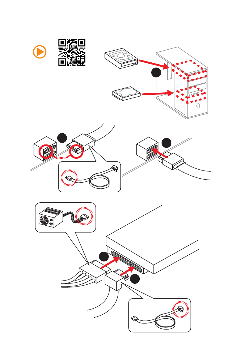
Installing SATA Drives
http://youtu.be/RZsMpqxythc
2
1
3
Quick Start
8
5
4
Page 9
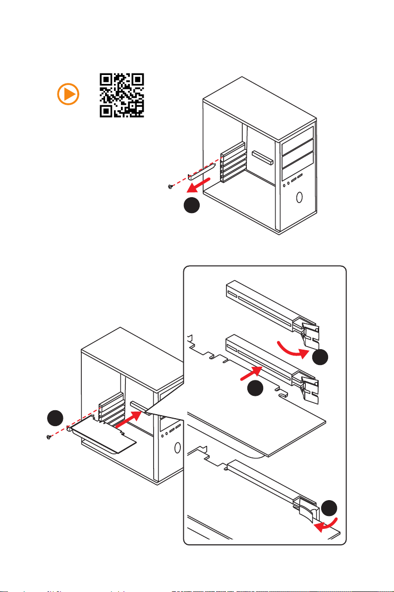
Installing a Graphics Card
http://youtu.be/mG0GZpr9w_A
1
2
3
5
4
Quick Start
9
Page 10
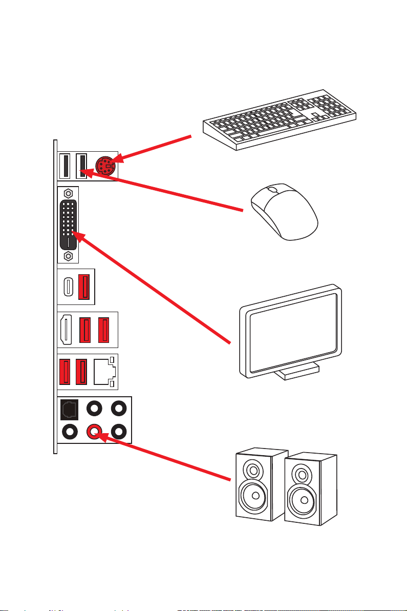
Connecting Peripheral Devices
10
Quick Start
Page 11
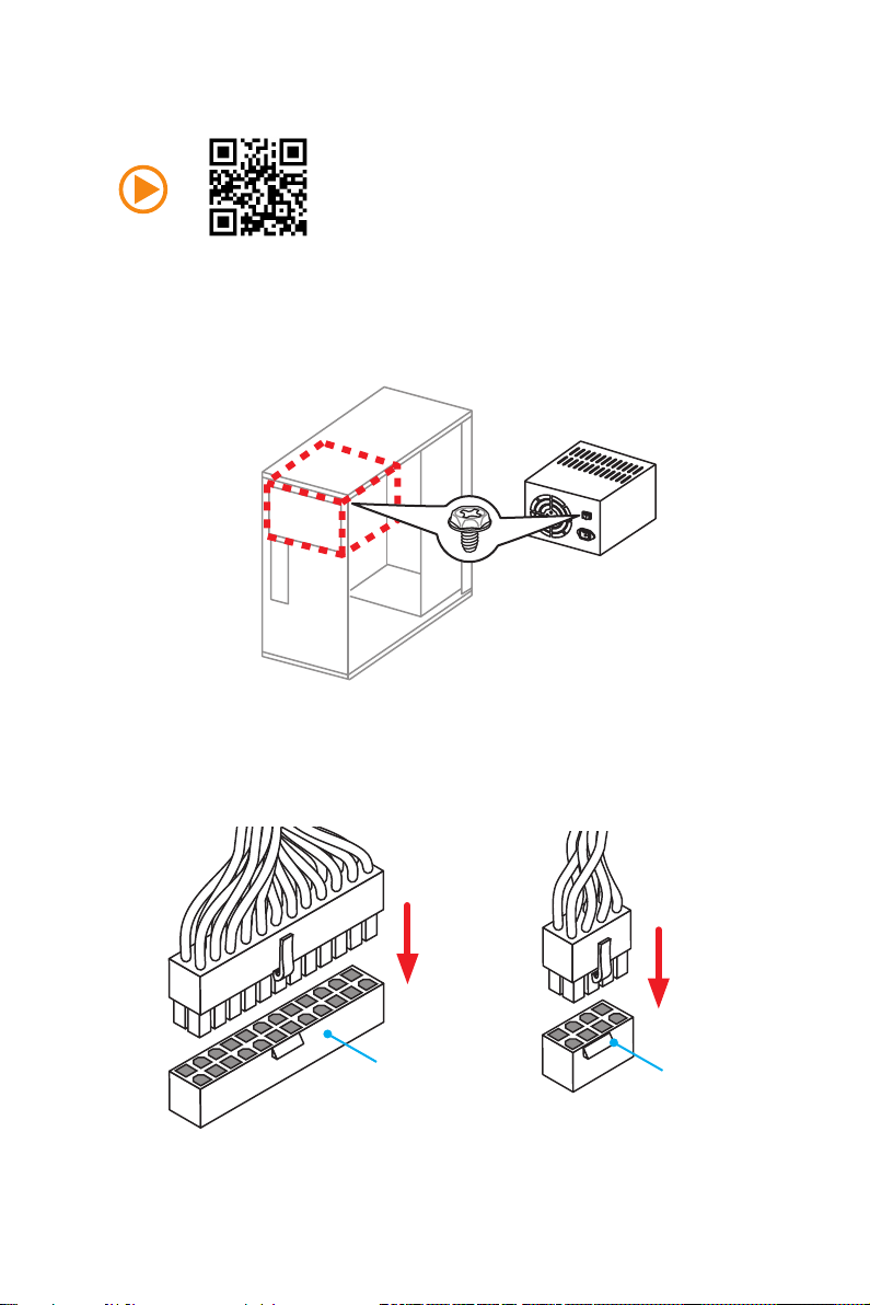
Connecting the Power Connectors
http://youtu.be/gkDYyR_83I4
JPWR1
JPWR2
Quick Start
11
Page 12
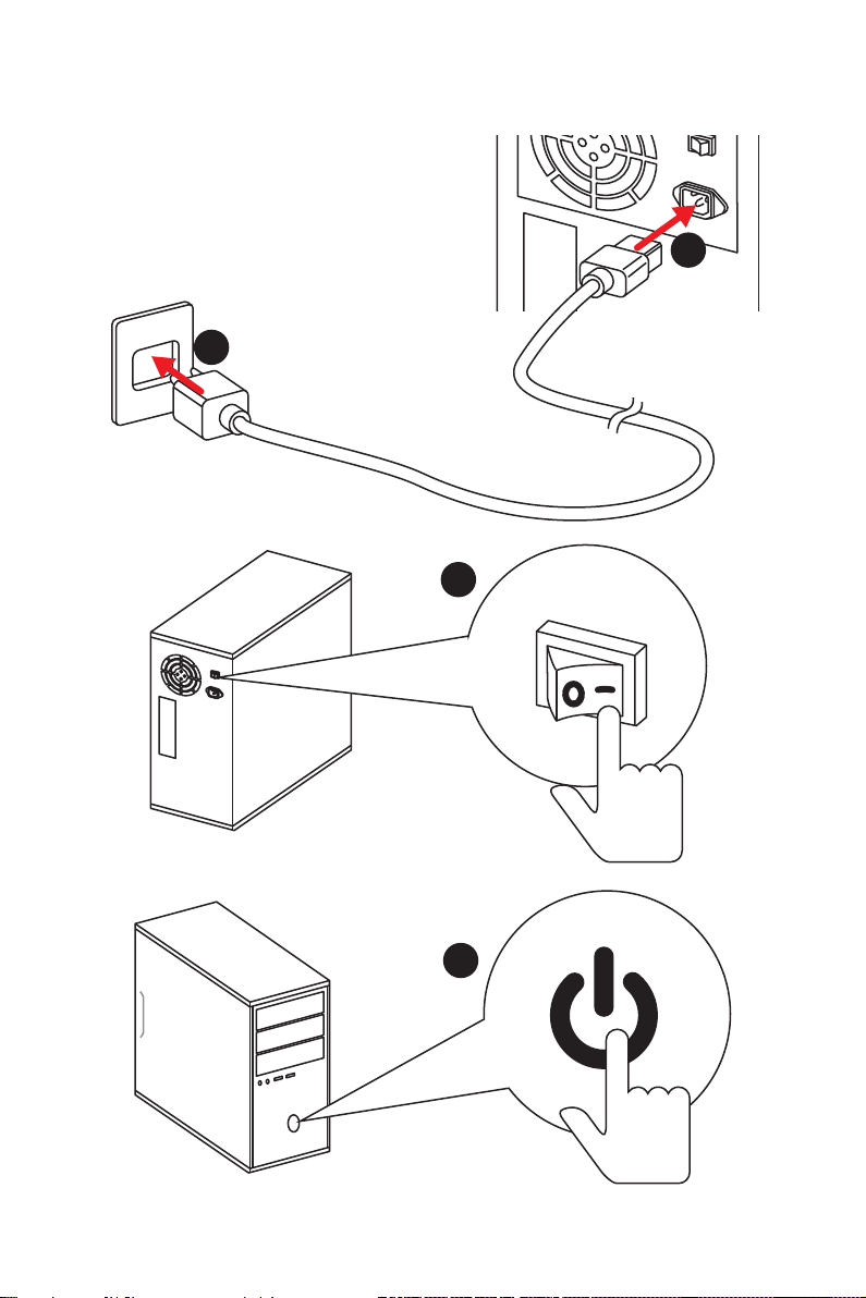
Power On
1
2
3
12
4
Quick Start
Page 13

Contents
Unpacking ................................................................................................................1
Safety Information ...................................................................................................2
Quick Start................................................................................................................3
Preparing Tools and Components ....................................................................... 3
Installing a Processor .......................................................................................... 4
Installing DDR4 memory ...................................................................................... 5
Connecting the Front Panel Header .................................................................... 6
Installing the Motherboard ................................................................................... 7
Installing SATA Drives ......................................................................................... 8
Installing a Graphics Card ................................................................................... 9
Connecting Peripheral Devices ......................................................................... 10
Connecting the Power Connectors .................................................................... 11
Power On ........................................................................................................... 12
Specifications ........................................................................................................15
Block Diagram ......................................................................................................22
Rear I/O Panel ........................................................................................................23
LAN Port LED Status Table ............................................................................... 23
Audio Ports Configuration .................................................................................. 23
Realtek HD Audio Manager ............................................................................... 24
Overview of Components ....................................................................................26
CPU Socket ....................................................................................................... 28
DIMM Slots ........................................................................................................ 29
PCI_E1~7: PCIe Expansion Slots...................................................................... 30
SATA1~6: SATA 6Gb/s Connectors .................................................................. 32
SE1_43-SE2_65: SATAe Connectors ............................................................... 32
M2_1~2: M.2 Slots ............................................................................................. 33
JPWR1~2: Power Connectors ........................................................................... 36
JUSB1~2: USB 2.0 Connectors......................................................................... 37
JUSB3: USB 3.1 Gen1 Connector ..................................................................... 37
JFP1, JFP2: Front Panel Connectors ................................................................ 38
JAUD1: Front Audio Connector ......................................................................... 38
JTPM1: TPM Module Connector ....................................................................... 38
JCOM1: Serial Port Connector .......................................................................... 39
JCI1: Chassis Intrusion Connector .................................................................... 39
CPUFAN1~2, SYSFAN1~3: Fan Connectors .................................................... 40
SLOW_1: Slow Mode Booting Switch ................................................................ 41
Contents
13
Page 14

JBAT1: Clear CMOS (Reset BIOS) Jumper ...................................................... 41
POST: Debug Code LED ................................................................................... 42
BIOS Setup .............................................................................................................43
Entering BIOS Setup ......................................................................................... 43
Resetting BIOS .................................................................................................. 44
Updating BIOS ................................................................................................... 44
Advanced Mode ................................................................................................ 47
SETTINGS ......................................................................................................... 48
Advanced ........................................................................................................... 48
Boot ................................................................................................................... 54
Security .............................................................................................................. 55
Save & Exit ........................................................................................................ 56
OC ..................................................................................................................... 57
M-FLASH ........................................................................................................... 65
OC PROFILE ..................................................................................................... 66
HARDWARE MONITOR .................................................................................... 67
Software Description ............................................................................................68
Installing Windows® 7/ 8.1/ 10 ........................................................................... 68
Installing Drivers ................................................................................................ 68
Installing Utilities ................................................................................................ 68
COMMAND CENTER ........................................................................................ 69
LIVE UPDATE 6 ................................................................................................ 73
GAMING APP .................................................................................................... 75
M-CLOUD .......................................................................................................... 79
RAMDISK .......................................................................................................... 82
Killer Network Manager ..................................................................................... 83
Nahimic .............................................................................................................. 84
XSplit Gamecaster V2 ....................................................................................... 86
®
Intel
Extreme Tuning Utility .............................................................................. 90
RAID Configuration ...............................................................................................91
Using Intel® Rapid Storage Technology Option ROM ....................................... 91
Degraded RAID Array ........................................................................................ 94
M.2 PCIe SSD RAID .......................................................................................... 96
Troubleshooting ...................................................................................................98
Regulatory Notices ...............................................................................................99
Contents
14
Page 15

Specifications
CPU
Supports 6th Gen Intel® Core™ i3/i5/i7 processors, and Intel®
Pentium® and Celeron® processors for Socket LGA1151
Chipset Intel
● 4x DDR4 memory slots, support up to 64GB
Memory
● Dual channel memory architecture
● Supports ECC, un-buffered memory
● Supports Intel
● 3x PCIe 3.0 x16 slots (support x16, x8/x8, x8/x8/x4 or x8/
Expansion Slots
● 4x PCIe 3.0 x1 slots
● 1x HDMI
Onboard Graphics
Multi-GPU
● 1x DVI-D port, support a maximum resolution of
● Supports 3-Way AMD
● Supports 2-Way NVIDIA
Intel
● 6x SATA 6Gb/s ports* (4 ports reserved for SATA
● 2x M.2 slots
Storage
● 2x SATAe ports (PCIe 3.0 x2)***
● Supports Intel
* M.2, SATA and SATAe ports maximum support 1x M.2_PCIe + 6x SATAs
** The Turbo U.2 Host Card is not included, please purchase separately.
*** SATAe port is backward compatible with SATA.
®
Z170 Express Chipset
▶ Supports DDR4 3600(OC)/ 3200(OC)/ 3000(OC)/
2800(OC)/ 2600(OC)/ 2400/ 2133 MHz
®
Extreme Memory Profile (XMP)
x8/x1 modes)
™
port, support a maximum resolution of
4096x2160@24Hz, 2560x1600@60Hz
1920x1200@60Hz
®
CrossFire™ Technology
®
SLI™ Technology
®
Z170 Express Chipset
Express port)
▶ Supports PCIe 3.0 x4 and SATA 6Gb/s standards,
4.2cm/ 6cm/ 8cm length M.2 SSD cards
▶ Supports PCIe 3.0 x4 NVMe Mini-SAS SSD with Turbo
U.2 Host Card**
®
Smart Response Technology for Intel
Core™ processors
or 1x M.2_SATA + 1x M.2_PCIe + 4x SATAs. Please refer to page 34 for
M.2 slots with examples of various combination possibilities.
Continued on next page
Specications
15
Page 16

Continued from previous page
®
Z170 Express Chipset
Intel
● Supports RAID 0, RAID1, RAID 5 and RAID 10 for SATA
RAID
storage devices
● Supports RAID 0 and RAID1 for M.2 PCIe storage
devices*
* M.2 PCIe RAID volume can be created with UEFI BIOS
● ASMedia
▶ 1x USB 3.1 Gen2 (SuperSpeed USB 10Gbps) port on
the back panel
▶ 1x USB 3.1 Gen2 Type-C port on the back panel
● Intel
USB
▶ 6x USB 3.1 Gen1 (SuperSpeed USB) ports (4 ports on
the back panel, 2 ports available through the internal
USB connector)
▶ 6x USB 2.0 (High-speed USB) ports (2 ports on the
back panel, 4 ports available through the internal USB
connectors)
● Realtek
Audio
● 7.1-Channel High Definition Audio
● Supports S/PDIF output
LAN 1x Killer
● 1x PS/2 keyboard/ mouse port
● 2x USB 2.0 ports
● 1x DVI-D port
● 1x USB 3.1 Gen2 port
Back Panel
Connectors
● 1x USB 3.1 Gen2 Type-C port
● 4x USB 3.1 Gen1 ports
● 1x HDMI
● 1x LAN (RJ45) port
● 1x Optical S/PDIF OUT connector
● 5x OFC audio jacks
®
ASM1142 Chipset
®
Z170 Express Chipset
®
ALC1150 Codec
™
E2400 Gigabit LAN controller
™
port
Specications
16
Continued on next page
Page 17

Continued from previous page
● 1x 24-pin ATX main power connector
● 1x 8-pin ATX 12V power connector
● 6x SATA 6Gb/s connectors
● 2x SATAe connectors
● 2x USB 2.0 connectors (supports additional 4 USB 2.0
ports)
● 1x USB 3.1 Gen1 connector (supports additional 2 USB
3.1 Gen1 ports)
Internal Connectors
I/O Controller NUVOTON NCT6793 Controller Chip
Hardware Monitor
● 2x 4-pin CPU fan connectors
● 3x 4-pin system fan connectors
● 1x Front panel audio connector
● 2x Front panel connectors
● 1x TPM module connector
● 1x Serial port connector
● 1x Chassis Intrusion connector
● 1x Slow mode switch
● 1x Clear CMOS jumper
● 1x 2-Digit Debug Code LED
● CPU/System temperature detection
● CPU/System fan speed detection
● CPU/System fan speed control
Form Factor
BIOS Features
● ATX Form Factor
● 12 in. x 9.6 in. (30.5 cm x 24.4 cm)
● 1x 128 Mb flash
● UEFI AMI BIOS
● ACPI 5.0, PnP 1.0a, SM BIOS 2.8
● Multi-language
Continued on next page
Specications
17
Page 18

Software
Continued from previous page
● Drivers
● COMMAND CENTER
● LIVE UPDATE 6
● FAST BOOT
● SUPER CHARGER
● GAMING APP
● M-CLOUD
● RAMDISK
● Killer Network Manager
● Nahimic Audio
● XSplit Gamecaster V2
®
● Intel
Extreme Tuning Utility
™
● Norton
● Google Chrome
Internet Security Solution
™
,Google Toolbar, Google Drive
● SteelSeries Engine 3
● CPU-Z
Continued on next page
Specications
18
Page 19

Enthusiast GAMING
Features
Continued from previous page
● AUDIO BOOST 3
▶ Isolated Audio PCB
▶ EMI Shielding
▶ Dual Headphone Amplifiers
▶ High Quality Audio Capacitors
▶ Golden Audio Connectors
● GAME BOOST
▶ Easy Overclocking
● GAMING LAN
▶ Killer E2400 Ethernet
▶ Killer Network Manager
▶ EMI Shielding
▶ Electric Wave Surge
● GAMING APP
▶ System Mode Switching: OC/Gaming/Silent
▶ Gaming Hotkey
▶ Gaming Mouse Control
● Optimized Thermal Design
▶ Dual Touch Thermal Design
● Nahimic
▶ Sound Effect Equalizer
▶ Microphone Noise Reduction
▶ HD Audio Recorder
● XSplit
▶ XSplit Gamecaster
▶ XSplit Broadcaster
● GAMING CERTIFIED
Continued on next page
Specications
19
Page 20

MSI Exclusive
Features
Continued from previous page
● CLICK BIOS 5
▶ EZ Mode & Advanced Mode Switching
▶ Board Explorer
▶ Hardware Monitor
● MILITARY CLASS 5
▶ Military Class Component
▶ Military Class Stability and Reliability
- ESD Protection
- EMI Protection
- Humidity Protection
- Circuit Protection
- High Temperature Protection
- Steel Armor PCIe Slots
- VGA Armor Slot
● COMMAND CENTER
▶ System Monitor
▶ Smart Fan Control
● RAMDISK
● LIVE UPDATE 6
● M-CLOUD
● CPU-Z
Continued on next page
Specications
20
Page 21

Specification
Highlights
Continued from previous page
● DDR4 Boost Support
▶ Dual-Channel DDR4 Memory Support
▶ Isolated DDR4 Circuit Design
▶ DDR4 XMP Ready
● PCI Express 3.0 Support
▶ 2-Way Nvidia SLI
▶ 3-Way AMD CrossFire
TM
Support
TM
Support
● USB 3.1 Gen2 Ready
▶ USB 3.1 Gen2 (10 Gb/s) Type-C Ready
▶ USB 3.1 Gen2 (10 Gb/s) Type-A Ready
● Twin Turbo M.2 Ready
▶ Dual M.2 RAID Support
▶ PCIe 3.0 x4 (32 Gb/s) Support
▶ PCIe / SATA Dual Mode Support
● SATA Express Support
● NVMe / AHCI Driver Support
● U.2 Support (Optional)
Specications
21
Page 22
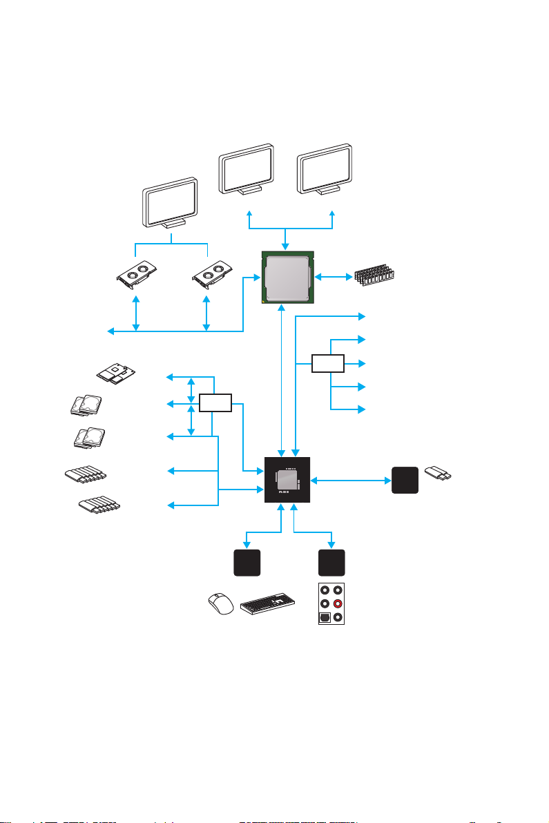
Block Diagram
x16x8
PCI Express Bus
x4
2 x M.2
2 x SATA Express
(4 x SATA 6Gb/s)
2 x SATA 6Gb/s
x2
HDMI DVI-D
DMI 3.0
Switch
PCI Express Bus
CPU
PCI Express Bus
2 Channel DDR4 Memory
x1
x1
x1
Switch
x1
x4
PCIe x1
PCIe x1
PCIe x1
PCIe x1
PCIe x4
Block Diagram
22
6 x USB 3.1 Gen1
6 x USB 2.0
LPC Bus
NV6793
Super I/O
P/S2 Mouse / Keyboard
Z170
PCI Express Bus
Realtek
ALC1150
Audio Jacks
x2
ASMEDIA
ASM1142
2 x USB 3.1 Gen2
Page 23
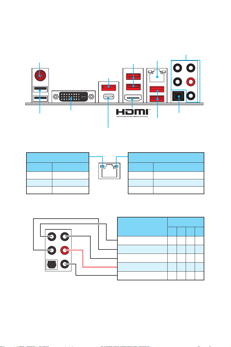
Rear I/O Panel
PS/2
USB 3.1 Gen2
USB 2.0
DVI-D
USB 3.1 Gen2 Type-C
LAN Port LED Status Table
Link/ Activity LED
Status Description
Off No link
Yellow Linked
Blinking Data activity
Audio Ports Configuration
USB 3.1 Gen1
LAN
USB 3.1 Gen1
Speed LED
Status Description
Off 10 Mbps connection
Green 100 Mbps connection
Orange 1 Gbps connection
Audio Ports
Optical S/PDIF-Out
Audio Ports
Center/ Subwoofer Out ● ●
Rear Speaker Out ● ● ●
Line-In/ Side Speaker Out ●
Line-Out/ Front Speaker Out ● ● ● ●
Mic In
Channel
2 4 6 8
(●: connected, Blank: empty)
Rear I/O Panel
23
Page 24
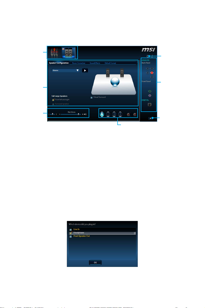
Realtek HD Audio Manager
After installing the Realtek HD Audio driver, the Realtek HD Audio Manager icon will
appear in the system tray. Double click on this icon to launch.
Device
Selection
Advanced
Settings
Application
Enhancement
Main Volume
Profiles
Jack Status
Connector
Strings
● Device Selection - allows you to select a audio output source to change the related
options. The check sign indicates the devices as default.
● Application Enhancement - the array of options will provide you a complete
guidance of anticipated sound effect for both output and input device.
● Main Volume - controls the volume or balance the right/left side of the speakers
that you plugged in front or rear panel by adjust the bar.
● Profiles - toggles between profiles.
● Advanced Settings - provides the mechanism to deal with 2 independent audio
streams.
● Jack Status - depicts all render and capture devices currently connected with your
computer.
● Connector Settings - configures the connection settings.
Auto popup dialog
When you plug into a device at an audio jack, a dialogue window will pop up asking
you which device is current connected.
Each jack corresponds to its default setting as shown on the next page.
Rear I/O Panel
24
Page 25
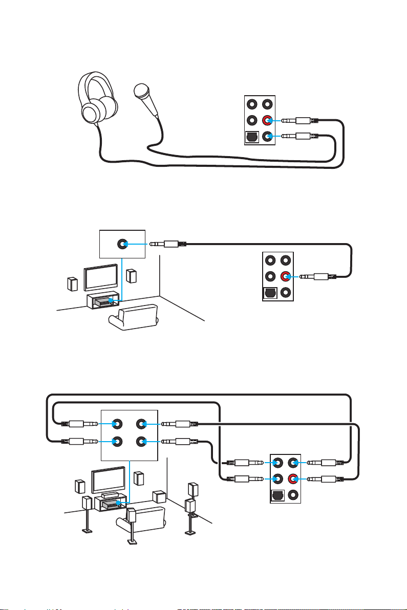
Audio jacks to headphone and microphone diagram
Audio jacks to stereo speakers diagram
AUDIO INPUT
Audio jacks to 7.1-channel speakers diagram
AUDIO INPUT
Rear Front
Side Center/
Subwoofer
Rear I/O Panel
25
Page 26
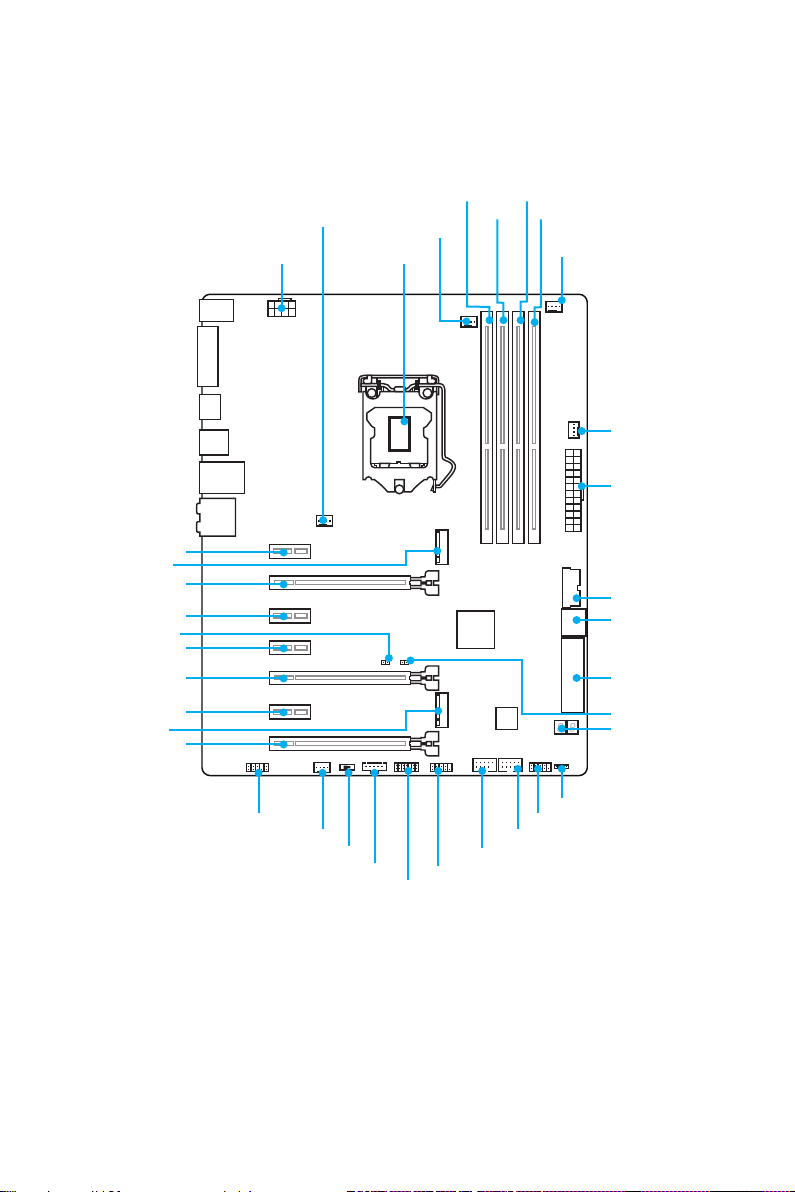
Overview of Components
PCI_E1
M2_1
PCI_E2
PCI_E3
JBAT1
PCI_E4
PCI_E5
PCI_E6
M2_2
PCI_E7
SYSFAN1 DIMM2
CPUFAN1
CPU SocketJPWR2
DIMM1
DIMM3
DIMM4
CPUFAN2
SYSFAN3
JPWR1
JUSB3
SATA1_2
SE1_43-SE2_65
JCI1
POST
* JTBT1 is used to connect a specific card.
Overview of Components
26
JAUD1
SYSFAN2
SLOW_1
JTBT1*
JTPM1
JCOM1
JUSB2
JUSB1
JFP1
JFP2
Page 27

Component Contents
Port Name Port Type Page
CPUFAN1~2, SYSFAN1~3 Fan Connectors 40
CPU Socket LGA1151 CPU Socket 28
DIMM1~4 DIMM Slots 29
JAUD1 Front Audio Connector 38
JBAT1 Clear CMOS (Reset BIOS) Jumper 41
JCI1 Chassis Intrusion Connector 39
JCOM1 Serial Port Connector 39
JFP1, JFP2 Front Panel Connectors 38
JPWR1~2 Power Connectors 36
JTPM1 TPM Module Connector 38
JUSB1~2 USB 2.0 Connectors 37
JUSB3 USB 3.1 Gen1 Connector 37
M2_1~2 M.2 Slots 33
PCI_E1~7 PCIe Expansion Slots 30
POST Debug Code LED 42
SATA1~6 SATA 6Gb/s Connectors 32
SE1_43-SE2_65 SATAe Connectors 32
SLOW_1 Slow Mode Booting Switch 41
Overview of Components
27
Page 28
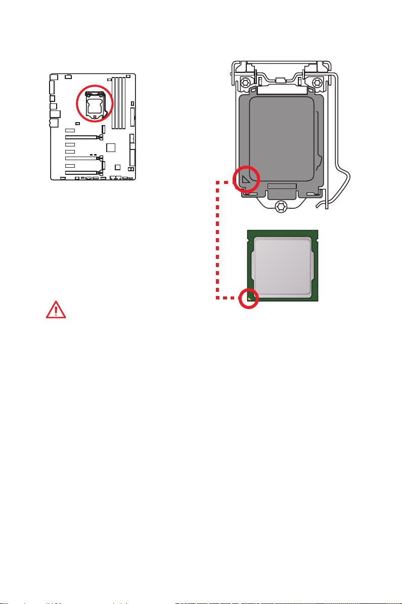
CPU Socket
Introduction to the LGA 1151 CPU
The surface of the LGA 1151 CPU has
two notches and a golden triangle to
assist in correctly lining up the CPU for
motherboard placement. The golden
triangle is the Pin 1 indicator.
Important
●
Always unplug the power cord from the power outlet before installing or removing
the CPU.
●
Please retain the CPU protective cap after installing the processor. MSI will deal
with Return Merchandise Authorization (RMA) requests if only the motherboard
comes with the protective cap on the CPU socket.
●
When installing a CPU, always remember to install a CPU heatsink. A CPU
heatsink is necessary to prevent overheating and maintain system stability.
●
Confirm that the CPU heatsink has formed a tight seal with the CPU before booting
your system.
●
Overheating can seriously damage the CPU and motherboard. Always make sure
the cooling fans work properly to protect the CPU from overheating. Be sure to
apply an even layer of thermal paste (or thermal tape) between the CPU and the
heatsink to enhance heat dissipation.
●
Whenever the CPU is not installed, always protect the CPU socket pins by covering
the socket with the plastic cap.
●
If you purchased a separate CPU and heatsink/ cooler, Please refer to the
documentation in the heatsink/ cooler package for more details about installation.
●
This motherboard is designed to support overclocking. Before attempting to
overclock, please make sure that all other system components can tolerate
overclocking. Any attempt to operate beyond product specifications is not
recommended. MSI® does not guarantee the damages or risks caused by
inadequate operation beyond product specifications.
Overview of Components
28
Page 29
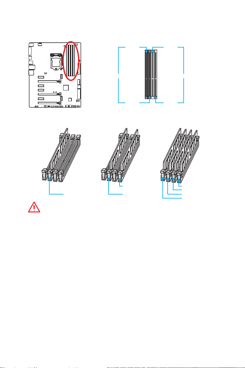
DIMM Slots
DIMM1 DIMM3
Channel A Channel B
DIMM2 DIMM4
Memory module installation recommendation
DIMM4 DIMM4
DIMM2 DIMM2 DIMM2
DIMM3
DIMM1
Important
●
Always insert memory modules in the DIMM2 slot first.
●
Due to chipset resource usage, the available capacity of memory will be a little less
than the amount of installed.
●
Based on Intel CPU specification, the Memory DIMM voltage below 1.35V is
suggested to protect the CPU.
●
Please note that the maximum capacity of addressable memory is 4GB or less
for 32-bit Windows OS due to the memory address limitation. Therefore, we
recommended that you to install 64-bit Windows OS if you want to install more than
4GB memory on the motherboard.
●
Some memory may operate at a lower frequency than the marked value when
overclocking due to the memory frequency operates dependent on its Serial
Presence Detect (SPD). Go to BIOS and find the Memory Try It! to set the
memory frequency if you want to operate the memory at the marked or at a higher
frequency.
●
It is recommended to use a more efficient memory cooling system for full DIMMs
installation or overclocking.
●
The stability and compatibility of installed memory module depend on installed CPU
and devices when overclocking.
Overview of Components
29
Page 30
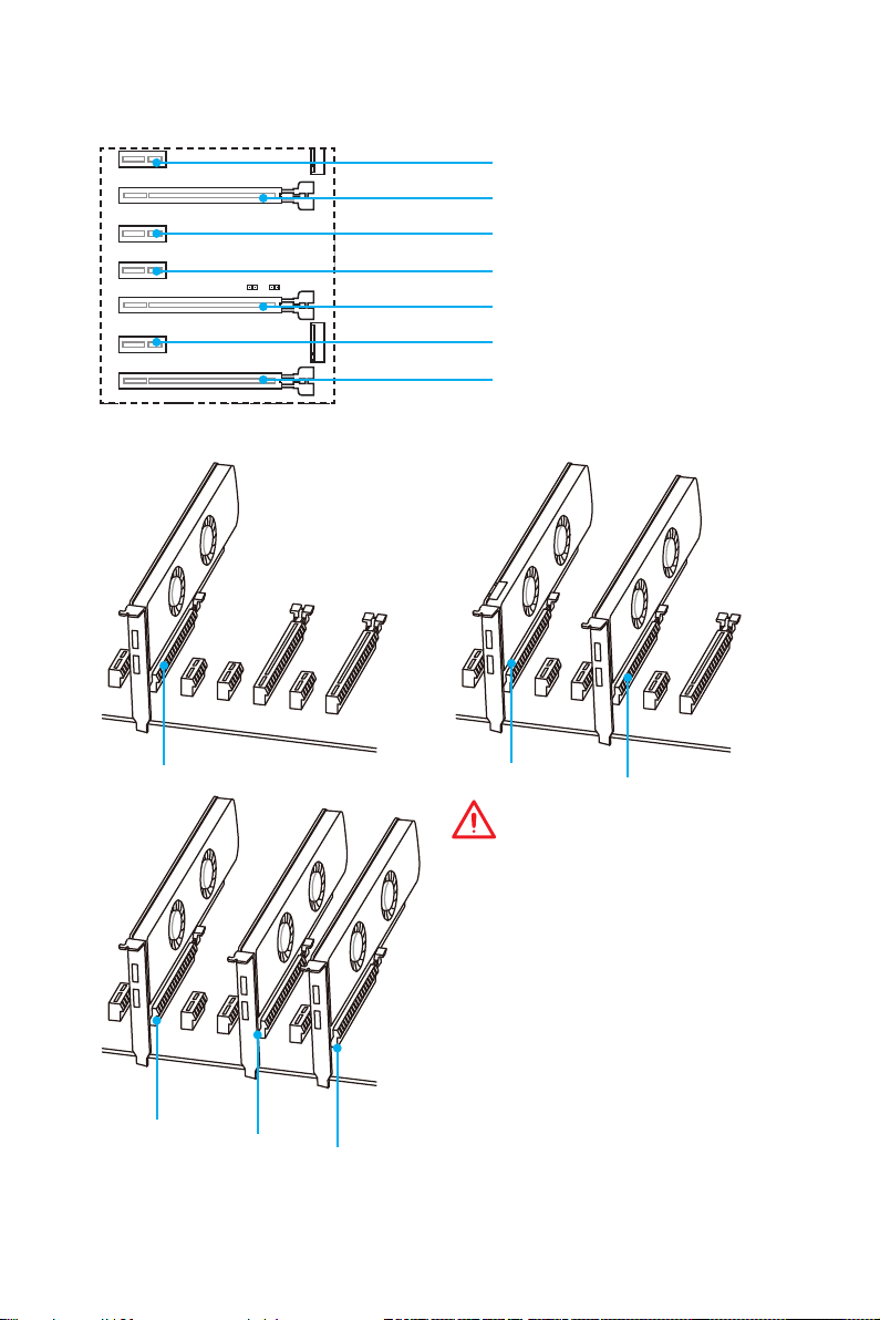
PCI_E1~7: PCIe Expansion Slots
PCI_E1: PCIe 3.0 x1 slot
PCI_E2: PCIe 3.0 x16/ x8 slot
PCI_E3: PCIe 3.0 x1 slot
PCI_E4: PCIe 3.0 x1 slot
PCI_E5: PCIe 3.0 x8 slot
PCI_E6: PCIe 3.0 x1 slot
PCI_E7: PCIe 3.0 x4/ x1 slot
Multiple graphics cards installation recommendation
x16
x8
Overview of Components
30
x8
x4
x8
x8
Important
●
PCI_E7 will only run x1 mode, when an
extension card is installed in PCI_E3/
PCI_E4/ PCI_E6 slot.
●
For a single PCIe x16 expansion
card installation with optimum
performance, using the PCI_E2 slot is
recommended.
●
When adding or removing expansion
cards, always turn off the power supply
and unplug the power supply power
cable from the power outlet. Read the
expansion card’s documentation to
check for any necessary additional
hardware or software changes.
Page 31

Installing SLI graphics cards
For power supply recommendations for SLI configurations, please refer to the user
guide of your graphics card to make sure you meet all the system requirements.
To install SLI graphics cards:
1. Turn off your computer and disconnect the power cord, install two graphics cards
into the PCI_E2 and PCI_E5 slots.
2. Connect the two cards together using the SLI Bridge Connector.
3. Connect all PCIe power connectors of the graphics cards.
4. Reconnect the power cord, power up the computer and install the drivers and
software included in your graphics card package.
5. Right-click the Windows desktop and select NVIDIA Control Panel from the
menu, click on Configure SLI, Surround, PhysX in the left task pane and select
Maximize 3D performance in the SLI configuration menu, and then click Apply.
Overview of Components
31
Page 32

SATA1~6: SATA 6Gb/s Connectors
These connectors are SATA 6Gb/s interface ports. Each connector can connect to
one SATA device.
SATA2
SATA1
SATA5
SATA3
SATA6
SATA4
SE1_43-SE2_65: SATAe Connectors
These connectors are SATAe (SATA Express) interface ports. Each SATAe connector
can be used with a single SATAe device or two legacy SATA devices.
SATA6
SATA5
SATA3
SATA4
SE2_65
(SATA_EX2)
SE1_43
(SATA_EX1)
Important
●
Please do not fold the SATA or SATAe cable at a 90-degree angle. Data loss may
result during transmission otherwise.
●
SATA or SATAe cables have identical plugs on either sides of the cable. However,
it is recommended that the flat connector be connected to the motherboard for
space saving purposes.
Overview of Components
32
Page 33

M2_1~2: M.2 Slots
M.2_1
M.2_2
Installing M.2 module
1. Remove the screw from
the base screw.
2. Remove the base
screw.
Important
●
Intel® RST only supports PCIe M.2 SSD with UEFI
ROM, does not support Legacy ROM.
Video Demonstration
Watch the video to learn how to Install
M.2 module.
http://youtu.be/JCTFABytrYA
1
2
3. Tighten the base screw
into the hole of the
distance to the M.2 slot
as the length your M.2
module.
4. Insert your M.2 module
into the M.2 slot at a
30-degree angle.
5. Put the screw in the
notch on the trailing edge
of your M.2 module and
tighten it into the base
screw.
4
3
30°
5
Overview of Components
33
Page 34

M.2/ SATA & SATAe combination table
Slot Available SATA/ SATAe connectors
M2_1 Empty SATA PCIe PCIe SATA Empty SATA PCIe
M2_2 PCIe PCIe PCIe SATA SATA SATA Empty Empty
SATA_EX1 ✓ ✓ ✓ ✓ ✓ ✓ ✓ ✓
SATA_EX2 ─ ─ ─ ─ ─ ─ ✓ ✓
SATA1 ✓ ─ ✓ ✓ ─ ✓ ─ ✓
SATA2 ✓ ─ ✓ ✓ ─ ✓ ─ ✓
SATA3 ✓ ✓ ✓ ✓ ✓ ✓ ✓ ✓
SATA4 ✓ ✓ ✓ ✓ ✓ ✓ ✓ ✓
SATA5 ─ ─ ─ ─ ─ ─ ✓ ✓
SATA6 ─ ─ ─ ─ ─ ─ ✓ ✓
(SATA: M.2 SATA SSD, PCIe: M.2 PCIe SSD, ✓: available, ─: unavailable)
M.2 slots with examples of various combination possibilities
1xM.2 PCIe SSD + 6xSATA HDDs
SATA2SATA5SATA6
PCIe
SATA1SATA3SATA4
1xM.2 PCIe SSD + 2xSATAe HDDs +
2xSATA HDDs
SATA2
SATA1SATA_EX1
SATA_EX2
1xM.2 PCIe SSD + 1xSATAe HDD +
4xSATA HDDs
SATA1SATA_EX1SATA3SATA4
PCIe
SATA2SATA5SATA5 SATA6SATA6
1xM.2 SATA SSD + 4xSATA HDDs
SATAPCIe
Overview of Components
34
Page 35

1xM.2 SATA SSD + 1xSATAe HDD +
2xSATA HDDs
SATA5SATA6
SATA_EX1
1xM.2 SATA SSD + 2xSATAe HDDs
SATASATA
SATA_EX1
SATA_EX2
2xM.2 SATA SSDs + 1xSATAe HDD2xM.2 SATA SSDs + 2xSATA HDDs
SATA
SATA3SATA4
SATA
2xM.2 PCIe SSDs + 4xSATA HDDs
SATA2
PCIe
PCIe
SATA1
SATA3
SATA4
1xM.2 PCIe SSD + 1xM.2 SATA SSD +
4xSATA HDDs
SATA2
PCIe
SATA
SATA1
SATA3
SATA4
SATA
SATA
SATA_EX1
2xM.2 PCIe SSDs + 1xSATAe
HDD+2xSATA HDDs
PCIe
PCIe
SATA_EX1SATA_EX1
1xM.2 PCIe SSD + 1xM.2 SATA SSD +
2xSATA HDDs + 1xSATAe HDD
SATA2 SATA2
PCIe
SATA
SATA1 SATA1
Overview of Components
35
Page 36

JPWR1~2: Power Connectors
These connectors allow you to connect an ATX power supply.
8
4 1
1 Ground 5 +12V
2 Ground 6 +12V
3 Ground 7 +12V
4 Ground 8 +12V
1 +3.3V 13 +3.3V
2 +3.3V 14 -12V
3 Ground 15 Ground
24
12
JPWR1
131
4 +5V 16 PS-ON#
5 Ground 17 Ground
6 +5V 18 Ground
7 Ground 19 Ground
8 PWR OK 20 Res
9 5VSB 21 +5V
10 +12V 22 +5V
11 +12V 23 +5V
12 +3.3V 24 Ground
5
JPWR2
Important
Make sure that all the power cables are securely connected to a proper ATX power
supply to ensure stable operation of the motherboard.
Overview of Components
36
Page 37

JUSB1~2: USB 2.0 Connectors
These connectors allow you to connect USB 2.0 ports on the front panel.
2 10
1
1 VCC 2 VCC
3 USB0- 4 USB1-
5 USB0+ 6 USB1+
7 Ground 8 Ground
9 No Pin 10 NC
9
Important
●
Note that the VCC and Ground pins must be connected correctly to avoid possible
damage.
●
In order to recharge your iPad,iPhone and iPod through USB ports, please install
MSI® SUPER CHARGER utility.
JUSB3: USB 3.1 Gen1 Connector
This connector allows you to connect USB 3.1 Gen1 ports on the front panel.
10 11
1
20
1 Power 11 USB2.0+
2 USB3_RX_DN 12 USB2.0-
3 USB3_RX_DP 13 Ground
4 Ground 14 USB3_TX_C_DP
5 USB3_TX_C_DN 15 USB3_TX_C_DN
6 USB3_TX_C_DP 16 Ground
7 Ground 17 USB3_RX_DP
8 USB2.0- 18 USB3_RX_DN
9 USB2.0+ 19 Power
10 Ground 20 No Pin
Important
Note that the Power and Ground pins must be connected correctly to avoid possible
damage.
Overview of Components
37
Page 38

JFP1, JFP2: Front Panel Connectors
These connectors connect to the switches and LEDs on the front panel.
2 10
JFP1
1
1 HDD LED + 2 Power LED +
3 HDD LED - 4 Power LED -
5 Reset Switch 6 Power Switch
7 Reset Switch 8 Power Switch
9 Reserved 10 No Pin
9
1
JFP2
1 Speaker - 2 Buzzer +
3 Buzzer - 4 Speaker +
JAUD1: Front Audio Connector
This connector allow you to connect audio jacks on the front panel.
2 10
1
1 MIC L 2 Ground
3 MIC R 4 NC
5 Head Phone R 6 MIC Detection
7 SENSE_SEND 8 No Pin
9 Head Phone L 10 Head Phone Detection
9
JTPM1: TPM Module Connector
This connector is for TPM (Trusted Platform Module). Please refer to the TPM security
platform manual for more details and usages.
2 14
1
1 LPC Clock 2 3V Standby power
3 LPC Reset 4 3.3V Power
5 LPC address & data pin0 6 Serial IRQ
7 LPC address & data pin1 8 5V Power
9 LPC address & data pin2 10 No Pin
11 LPC address & data pin3 12 Ground
13 LPC Frame 14 Ground
13
Overview of Components
38
Page 39

JCOM1: Serial Port Connector
This connector allows you to connect the optional serial port with bracket.
2 10
1
9
1 DCD 2 SIN
3 SOUT 4 DTR
5 Ground 6 DSR
7 RTS 8 CTS
9 RI 10 No Pin
JCI1: Chassis Intrusion Connector
This connector allows you to connect the chassis intrusion switch cable.
Normal
(default)
Trigger the chassis
intrusion event
Using chassis intrusion detector
1. Connect the JCI1 connector to the chassis intrusion switch/ sensor on the
chassis.
2. Close the chassis cover.
3. Go to BIOS > Settings > Security > Chassis Intrusion Configuration.
4. Set Chassis Intrusion to Enabled.
5. Press F10 to save and exit and then press the Enter key to select Yes.
6. Once the chassis cover is opened again, a warning message will be displayed on
screen when the computer is turned on.
Resetting the chassis intrusion warning
1. Go to BIOS > Settings > Security > Chassis Intrusion Configuration.
2. Set Chassis Intrusion to Reset.
3. Press F10 to save and exit and then press the Enter key to select Yes.
Overview of Components
39
Page 40

CPUFAN1~2, SYSFAN1~3: Fan Connectors
Fan connectors can be classified as PWM (Pulse Width Modulation) Mode and
Voltage Mode. PWM Mode fan connectors provide constant 12V output and adjust fan
speed with speed control signal. Voltage Mode fan connectors control fan speed by
changing voltage. Therefore, when you plug a 3-pin (Non-PWM) fan to a PWM Mode
fan connector, the fan speed will be always maintained at 100%, and that could be
noisy.
PWM Mode fan connector
1
CPUFAN1/ CPUFAN2
1 Ground 2 +12V
3 Sense 4 Speed Control Signal
Voltage Mode fan connector
1
SYSFAN1/ SYSFAN2
1 Ground 2 Voltage Control
3 Sense 4 NC
Controlling the fan speed
There are two ways to manage fan speed. One is to go to BIOS > HARDWARE
MONITOR. The other is to use COMMAND CENTER application.
1
SYSFAN3
BIOS > HARDWARE MONITOR COMMAND CENTER
Both methods offer gradient points of the fan speed that allow you to adjust fan speed
in relation to CPU temperature.
Overview of Components
40
Page 41

SLOW_1: Slow Mode Booting Switch
This switch is used for LN2 cooling solution, that provides the extreme overclocking
conditions, to boot at a stable processor frequency and to prevent the system from
crashing.
Normal
(Default)
Enabled
Important
Users will try extreme low temperature overclocking at their own risks. The
overclocking results will vary according to the CPU version.
JBAT1: Clear CMOS (Reset BIOS) Jumper
There is CMOS memory onboard that is external powered from a battery located on
the motherboard to save system configuration data. If you want to clear the system
configuration, set the jumpers to clear the CMOS memory.
Keep Data
(default)
Resetting BIOS to default values
1. Power off the computer and unplug the power cord.
2. Use a jumper cap to short JBAT1 for about 5-10 seconds.
3. Remove the jumper cap from JBAT1.
4. Plug the power cord and power on the computer.
Clear CMOS/
Reset BIOS
Overview of Components
41
Page 42

POST: Debug Code LED
Debug code LED table
Post Status
02,07 Power on CPU Initialization
03,08 Power on North Bridge Initialization
04,09 Power on South Bridge Initialization
0B Power on Cache Initialization
11~14,32~36,56~5A Early CPU Initialization
15~18,37~3A Early North Bridge Initialization
19~1C,3B~3E Early South Bridge Initialization
1D~2F,31,3F~4E,50~55 Early Memory Initialization
63~67,D0 Late CPU Initialization
69~6F,D1 Late North Bridge Initialization
70~77,D2 Late South Bridge Initialization
92~96,B5,D4 PCI bus Initialization
97,98,99,B2,D5~D7
9A~A7,B4
A8,A9,AB Start of Setup. BIOS setup if needed/ requested.
Console Output/Input devices/Console initialization and
Load Option ROM (VGA, RAID, parallel ports, serial
ports……)
Onboard devices Initialize and Detect (USB/ SATA/
SCSI……)
AD/AE Ready To Boot event/Legacy Boot event
CPU temperature Fully boot
Overview of Components
42
Page 43

BIOS Setup
The default settings offer the optimal performance for system stability in normal
conditions. You should always keep the default settings to avoid possible system
damage or failure booting unless you are familiar with BIOS.
Important
●
BIOS items are continuously update for better system performance. Therefore,
the description may be slightly different from the latest BIOS and should be for
reference only. You could also refer to the HELP information panel for BIOS item
description.
●
The pictures in this chapter are for reference only and may vary from the product
you purchased.
Entering BIOS Setup
Please refer the following methods to enter BIOS setup.
● Press Delete key, when the Press DEL key to enter Setup Menu, F11 to enter
Boot Menu message appears on the screen during the boot process.
● Use MSI FAST BOOT application. Click on GO2BIOS button and choose OK. The
system will reboot and enter BIOS setup directly.
Click on GO2BIOS
● Enable the GO2BIOS item (SETTING > Boot > GO2BIOS) in BIOS setup
Advanced mode (F7). It allows the system to enter BIOS setup directly by pressing
the power button for 4 seconds upon bootup.
Function key
Key Function Key Function
F1 General Help F3 Enter Favorites menu
F4 Enter CPU Specifications menu F5 Enter Memory-Z menu
F6 Load optimized defaults F8 Load Overclocking Profile
F9 Save Overclocking Profile F10 Save Change and Reset*
* When you press F10, a confirmation window appears and it provides the modification
information. Select between Yes or No to confirm your choice.
BIOS Setup
43
Page 44

Resetting BIOS
You might need to restore the default BIOS setting to solve certain problems. There
are several ways to reset BIOS:
● Go to BIOS and press F6 to load optimized defaults.
● Short the Clear CMOS jumper on the motherboard.
● Press the Clear CMOS button, on the rear I/O panel. (Only for the motherboard
with clear CMOS button.)
Updating BIOS
Updating BIOS with M-FLASH
Before updating:
Please download the latest BIOS file that matches your motherboard model from MSI
website. And then save the BIOS file into the USB flash drive.
Updating BIOS:
1. Press Del key to enter the BIOS Setup during POST.
2. Insert the USB flash drive that contains the update file into the computer.
3. Select the M-FLASH tab and click on Yes to reboot the system and enter the flash
mode.
4. Select a BIOS file to perform the BIOS update process.
5. After the flashing process is 100% completed, the system will reboot
automatically.
Updating the BIOS with Live Update 6
Before updating:
Make sure the LAN driver is already installed and the internet connection is set
properly.
Updating BIOS:
1. Install and launch MSI LIVE UPDATE 6.
2. Select Manual scan.
3. Check MB BIOS box and click on Scan button.
4. Select the MB BIOS and click on
file.
5. Click Next and choose In Windows mode. And then click Next and Start to start
updating BIOS.
6. After the flashing process is 100% completed, the system will restart
automatically.
icon to download and install the latest BIOS
44
BIOS Setup
Page 45

EZ Mode
At EZ mode, it provides the basic system information and allows you to configure the
basic setting. To configure the advanced BIOS settings, please enter the Advanced
Mode by pressing the Setup Mode switch or F7 function key.
XMP switch
Favorites ScreenshotSetup Mode switch
Language
System
information
GAME BOOST
toggle
Information
display
M-Flash
Favorites
Hardware
Monitor
Boot device
priority bar
Function
buttons
● Function buttons - enable or disable the LAN Option ROM, Fast Boot, HD audio
controller, AHCI, RAID, CPU Fan Fail Warning Control and BIOS Log Review
by clicking on their respective button.
● Hardware Monitor - click on this button to display the Hardware Monitor menu
that allows you to manually control the fan speed by percentage.
● M-Flash - click on this button to display the M-Flash menu that provides the way to
update BIOS with a USB flash drive.
● Information display - click on the CPU, Memory, Storage, Fan Info and Help
buttons on left side to display related information.
● Boot device priority bar - you can move the device icons to change the boot
priority. The boot priority from high to low is left to right.
● System information - shows the CPU/ DDR speed, CPU/ MB temperature, MB/
CPU type, memory size, CPU/ DDR voltage, BIOS version and build date.
● Language - allows you to select the language of BIOS setup.
● Screenshot - press this tab or the F12 key to take a screenshot and save it to USB
flash drive (FAT/ FAT32 format only).
● Setup Mode switch - press this tab or the F7 key to switch between Advanced
mode and EZ mode.
● XMP switch - click on the inner circle to enable/ disable the X.M.P. (Extreme
Memory Profile). Switch the outer circle to select the X.M.P. profile. This switch will
only be available if the X.M.P. supported memory module is installed.
BIOS Setup
45
Page 46

● GAME Boost toggle - click on it to toggle the GAME BOOST for OC.
Important
Please don’t make any changes in OC menu and don’t load defaults to keep the
optimal performance and system stability after activating the GAME Boost function.
● Favorites - press any Favorites tab or the F3 key to enter Favorites menu. It
allows you to create personal BIOS menu where you can save and access favorite/
frequently-used BIOS setting items.
▶ Default HomePage - allows you to select a BIOS menu (e.g. SETTINGS,
OC...,etc) as the BIOS home page.
▶ Favorite1~5 - allows you to add the frequently-used/ favorite BIOS setting items in
one page.
▶ To add a BIOS item to a favorite page (Favorite 1~5)
1. Select a BIOS item in SETTINGS or OC menu.
2. Right-click or press F2 key.
3. Choose a favorite page and click on OK.
▶ To delete a BIOS item from favorite page
1. Select a BIOS item in favorite page (Favorite 1~5)
2. Right-click or press F2 key.
3. Choose Delete and click on OK.
46
BIOS Setup
Page 47

Advanced Mode
Press Setup Mode switch or F7 function key can switch between EZ Mode and
Advanced Mode in BIOS setup.
GAME BOOST
toggle
XMP switch
Favorites ScreenshotSetup Mode switch
Language
System
information
Boot device
priority bar
BIOS menu
selection
Menu display
BIOS menu
selection
● GAME BOOST toggle / XMP switch/ Setup Mode switch/ Screenshot/
Favorites/ Language/ System information/ Boot device priority bar - please
refer to the descriptions of EZ Mode Overview section.
● BIOS menu selection - the following options are available:
▶ SETTINGS - allows you to specify the parameters for chipset and boot devices.
▶ OC - allows you to adjust the frequency and voltage. Increasing the frequency may
get better performance.
▶ M-FLASH - provides the way to update BIOS with a USB flash drive.
▶ OC PROFILE - allows you to manage overclocking profiles.
▶ HARDWARE MONITOR - allows you to set the speeds of fans and monitor
voltages of system.
▶ BOARD EXPLORER - provides the information of installed devices on this
motherboard.
● Menu display - provides BIOS setting items and information to be configured.
BIOS Setup
47
Page 48

SETTINGS
System Status
▶System Date
Sets the system date. Use tab key to switch between date elements.
The format is <day> <month> <date> <year>.
<day> Day of the week, from Sun to Sat, determined by BIOS. Read-only.
<month> The month from Jan. through Dec.
<date> The date from 1 to 31 can be keyed by numeric function keys.
<year> The year can be adjusted by users.
▶System Time
Sets the system time. Use tab key to switch between time elements.
The time format is <hour> <minute> <second>.
▶SATA PortX
Shows the information of connected SATA device.
Important
If the connected SATA device is not displayed, turn off computer and re-check SATA
cable and power cable connections of the device and motherboard.
▶System Information
Shows detailed system information, including CPU type, BIOS version, and Memory
(read only).
▶DMI Information
Shows system information, desktop Board Information and chassis Information. (Read
only).
Advanced
▶PCI Subsystem Settings
Sets PCI, PCI express interface protocol and latency timer. Press <Enter> to enter the
sub-menu.
BIOS Setup
48
Page 49

▶PEG X - Max Link Speed [Auto]
Sets PCI Express protocol of PCIe x16 slots for matching dierent installed
devices.
[Auto] This item will be congured automatically by BIOS.
[Gen1] Enables PCIe Gen1 support only.
[Gen2] Enables PCIe Gen2 support only.
[Gen3] Enables PCIe Gen3 support only.
▶PCI Latency Timer [32]
Sets latency timer of PCI interface device.
[Options: 32, 64, 96, 128, 160, 192, 224, 248 PCI Bus clocks]
▶ACPI Settings
Sets ACPI parameters of onboard power LED behaviors. Press <Enter> to enter the
sub-menu.
▶Power LED [Blinking]
Sets shining behaviors of the onboard Power LED.
[Dual Color] The power LED turns to another color to indicate the S3 state.
[Blinking] The power LED blinks to indicate the S3 state.
▶Integrated Peripherals
Sets integrated peripherals' parameters, such as LAN, HDD, USB and audio. Press
<Enter> to enter the sub-menu.
▶Onboard LAN Controller [Enabled]
Enables or disables the onboard LAN controller.
▶LAN Option ROM [Disabled]
Enables or disables the legacy network Boot Option ROM for detailed settings.
This item will appear when Onboard LAN Controller is enabled.
[Enabled] Enables the onboard LAN Boot ROM.
[Disabled] Disables the onboard LAN Boot ROM.
▶Network Stack [Disabled]
Sets UEFI network stack for optimizing IPv4 / IPv6 function.
[Enabled] Enables UEFI network stack.
[Disabled] Disables UEFI network stack.
▶Ipv4 PXE Support [Disabled]
When “Enabled”, the system UEFI network stack will support Ipv4 protocol. This
item will appear when “Network Stack” is enabled.
[Enabled] Enables the Ipv4 PXE boot support.
[Disabled] Disables the Ipv4 PXE boot support.
BIOS Setup
49
Page 50

▶Ipv6 PXE Support [Disabled]
When “Enabled”, the system UEFI network stack will support Ipv6 protocol. This
item will appear when “Network Stack” is enabled.
[Enabled] Enables the Ipv6 PXE boot support.
[Disabled] Disables the Ipv6 PXE boot support.
▶SATA Mode [AHCI Mode]
Sets the operation mode of the onboard SATA controller.
[AHCI Mode] Specify the AHCI mode for SATA storage devices. AHCI (Advanced
[RAID Mode] Enables RAID function for SATA storage devices.
▶M2_1/ M2_2-RST Pcie Storage Remapping [Disabled]
Enables or disables Intel Rapid Storage Technology for M.2 PCIe/ SATAe device.
This item will appear when SATA Mode is set to RAID Mode and Windows
8.1/10 WHQL Support is enabled.
▶SATAx Hot Plug [Disabled]
Allows user to enable or disable the SATA hot plug support.
[Enabled] Enables hot plug support for the SATA ports.
[Disabled] Disables hot plug support for the SATA ports.
▶HD Audio Controller [Enabled]
Enables or disables the onboard High Denition Audio controller.
▶HPET [Enabled]
Enables or disables the HPET (High Precision Event Timers) support.
▶Integrated Graphics Conguration
Adjusts integrated graphics settings for optimum system. Press <Enter> to enter the
sub-menu.
▶Initiate Graphic Adapter [PEG]
Selects a graphics device as the primary boot device.
[IGD] Integrated Graphics Display.
[PEG] PCI-Express Graphics Device.
▶Integrated Graphics Share Memory [64M]
Selects a xed amount of system memory allocated to the onboard graphics. This
item will appear when IGD Multi-Monitor is enabled.
▶IGD Multi-Monitor [Disabled]
Enables or disables the multi-screen output from integrated graphics and external
graphics card.
[Enabled] Enables multi-screen function for both integrated and external
[Disabled] Disables this function.
Host Controller Interface) oers some advanced features to enhance
the speed and performance of SATA storage device, such as Native
Command Queuing (NCQ) and hot-plugging.
graphics cards.
50
BIOS Setup
Page 51

▶USB Conguration
Sets the onboard USB controller and device function. Press <Enter> to enter the submenu.
▶USB Controller [Enabled]
Enables or disables all USB controller.
▶XHCI Hand-off [Enabled]
Enables or disables XHCI hand-o support for the operating system without XHCI
hand-o feature. This item will appear when USB Controller is enabled.
▶Legacy USB Support [Enabled]
Sets Legacy USB function support.
[Auto] The system will automatically detect if any USB device is connected
[Enabled] Enable the USB support under legacy mode.
[Disabled] The USB devices will be unavailable under legacy mode.
▶Super IO Conguration
Sets system Super I/O chip parameters. Press <Enter> to enter the sub-menu.
▶Serial (COM) Port 0 Configuration
Sets detailed conguration of serial(COM) port. Press <Enter> to enter the sub-
menu.
▶Serial (COM) Port 0 [Enabled]
Enables or disables serial (COM) port 1.
▶Serial (COM) Port 0 Settings [Auto]
Sets serial port (COM). If set to Auto, BIOS will optimize the IRQ automatically or
you can set it manually.
▶Power Management Setup
Sets system Power Management of EuP2013 and AC Power Loss behaviors. Press
<Enter> to enter the sub-menu.
▶EuP 2013 [Disabled]
Enables or disables the system power consumption according to EuP2013
regulation.
[Enabled] Optimize the system power consumption according to EuP 2013
[Disabled] Disables this function.
▶Restore after AC Power Loss [Power Off]
Sets the system behaviors while encountering the AC power loss.
[Power O] Leaves the system in power o state after restoring AC power.
[Power On] Boot up the system after restoring AC power.
[Last State] Restores the system to the previous state (power on/ power o)
and enable the legacy USB support.
regulation. It will not support S4 & S5 wake up by USB, PCI and
PCIe devices.
before AC power loss.
BIOS Setup
51
Page 52

▶On board LED Control [On]
Enables or disables the actions of onboard LEDs.
[On] Enables the actions of onboard LEDs.
[O] Disables the actions of power, reset, PCH, audio LEDs.
▶Windows OS Conguration
Sets Windows 8/ 8.1 detailed conguration and behaviors. Press <Enter> to enter
the sub-menu.
▶Windows 8.1/ 10 WHQL Support [Disabled]
Enables the supports for Windows 8.1/ 10 or disables for other operating systems.
Before enabling this item, make sure all installed devices & utilities (hardware &
software) should meet the Windows 8.1/ 10 requirements.
[Enabled] The system will switch to UEFI mode to meet the Windows
[Disabled] Disables this function.
▶MSI Fast Boot [Disabled]
MSI Fast Boot is the fastest way to boot the system. It will disable more devices to
speed up system boot time which is faster than the boot time of Fast Boot.
[Enabled] Enables the MSI Fast Boot function to speed up booting time. And
[Disabled] Disables MSI Fast Boot.
equirement.
the following Fast Boot eld will be disabled and xed.
Important
When MSI Fast Boot is enabled, you can use MSI FAST BOOT application to enter
BIOS setup if needed. Please refer Entering BIOS Setup section for details.
▶Fast Boot [Disabled/ windows7, Enabled/ windows 8.1/ 10]
Enables or disables the fast boot feature for Windows 8.1/ 10. This item will only be
available when MSI Fast Boot is disabled.
[Enabled] Enables the Fast Boot conguration to accelerate system boot time.
[Disabled] Disables the Fast Boot conguration.
▶Internal GOP Configuration
Manages the onboard Graphics Output Protocol (GOP). Press <Enter> to enter the
sub-menu. This sub-menu will appear when Windows 8.1/ 10 WHQL Support is
enabled.
▶Secure Boot
Sets the Windows secure boot to prevent the unauthorized accessing. Press
<Enter> to enter the sub-menu. This sub-menu will appear when Windows 8.1/ 10
WHQL Support is enabled.
▶Secure Boot Support [Disabled]
Enables or disables secure boot support.
[Enabled] Enables the secure boot function and allow you to set the secure
[Disabled] Disables this function.
boot settings.
52
BIOS Setup
Page 53

▶Secure Boot Mode [Standard]
Selects the secure boot mode. This item is to select how the secure boot keys be
loaded. This item appears when Secure Boot Support is enabled.
[Standard] The system will automatically load the secure keys from BIOS.
[Custom] Allows user to congure the secure boot settings and manually load
▶Key Management
Manages the secure boot keys. Press <Enter> to enter the sub-menu. This submenu will appear when Secure Boot Mode sets to [Custom].
▶Wake Up Event Setup
Sets system wake up behaviors for different sleep modes. Press <Enter> to enter the
sub-menu.
▶Wake Up Event By [BIOS]
Selects the wake up event by BIOS or operating system.
[BIOS] Activates the following items, set wake up events of these items.
[OS] The wake up events will be dened by OS.
▶Resume By RTC Alarm [Disabled]
Disables or enables the system wake up by RTC Alarm.
[Enabled] Enables the system to boot up on a scheduled time/ date.
[Disabled] Disables this function.
▶Date (of month) Alarm/ Time (hh:mm:ss) Alarm
Sets RTC alarm date/ Time. If Resume By RTC Alarm is set to [Enabled], the
system will automatically resume (boot up) on a specied date/hour/minute/second
in these elds (using the <+> and <-> to select the date & time settings).
▶Resume By PCI-E Device [Disabled]
Enables or disables the system wake up by PCI express devices.
[Enabled] Enables the system to be awakened from the power saving modes
[Disabled] Disables this function.
▶Resume by USB Device [Disabled]
Enables or disables the system wake up by USB devices.
[Enabled] Enables the system to be awakened from sleep state when activity
[Disabled] Disables this function.
▶Resume From S3/S4/S5 by PS/2 Mouse [Disabled]
Enables or disables the system wake up by PS/2 mouse.
[Enabled] Enables the system to be awakened from S3/ S4/ S5 state when
[Disabled] Disables this function.
the secure keys.
when activity or input signal of PCIe device is detected. Note:
enables this Item to support Resume by USB Device with third party
USB 3.0 port.
of USB device is detected.
activity of PS/2 mouse is detected.
BIOS Setup
53
Page 54

▶Resume From S3/S4/S5 by PS/2 Keyboard [Disabled]
Enables or disables the system wake up by PS/2 keyboard.
[Any Key] Enables the system to be awakened from S3/ S4/ S5 state when
[Hot Key] Enables the system to be awakened from S3/ S4/ S5 state when
[Disabled] Disables this function.
activity of any key on PS/2 keyboard is detected.
activity of hot key on PS/2 keyboard is detected.
Boot
Sets the sequence of system boot devices.
▶Full Screen Logo Display [Enabled]
Enables or disables to show the full screen logo while system POST.
[Enabled] Shows the logo in full screen.
[Disabled] Shows the POST messages.
▶GO2BIOS [Disabled]
Allows system to enter BIOS setup directly by pressing the Power button for 4 sec
upon bootup.
[Enabled] The system boots straight to the BIOS setup by long pressing the power
[Disabled] Disables this function.
▶Bootup NumLock State [On]
Select the keyboard NumLock state upon bootup.
▶AUTO CLR_CMOS [Disabled]
Enables or disables the CMOS data to be resumed automatically when the booting
process hang-up over 5 seconds.
▶Boot Mode Select [LEGACY+UEFI]
Sets the system boot mode from legacy or UEFI architecture depending on OS
installation requirement. This item will become un-selectable and will be configured
automatically by BIOS when Windows 8.1/ 10 WHQL Support is enabled.
[UEFI] Enables UEFI BIOS boot mode support only.
[LEGACY+UEFI] Enables both Legacy BIOS boot mode and UEFI BIOS boot
▶FIXED BOOT ORDER Priorities
Sets device priority for system boot.
▶Boot Option Priorities
These items are used to prioritize the installed boot devices.
button about 4 seconds when the system is off.
mode.
54
BIOS Setup
Page 55

Security
▶Administrator Password
Sets administrator password for system security. User has full rights to change the
BIOS items with administrator password. After setting the administrator password, the
state of this item will show “Installed”.
▶User Password
Sets User Password for system security. User has limited rights to change the BIOS
items with user password. This item will be available when administrator password is
set. After setting the user password, the state of this item will show “Installed”.
▶Password Check [Setup]
Selects a condition that will request the password.
[Setup] A password will be requested for entering the BIOS Setup.
[Boot] A password will be requested for booting the system.
▶Password Clear [Enabled]
Enables or disables the clear CMOS behavior to clear a set password.
[Enabled] The password will be erased after clear CMOS.
[Disabled] The password will always be kept.
Important
When selecting the Administrator / User Password items, a password box will appear
on the screen. Type the password then press <Enter>. The password typed now will
replace any previous set password from CMOS memory. You will be prompted to
confirm the password. You may also press <Esc> to abort the selection.
To clear a set password, press <Enter> when you are prompted to enter a new
password. A message will confirm the password is being disabled. Once the password
is disabled, you can enter the setup and OS without authorization.
▶Trusted Computing
Sets TPM (Trusted Platform Module) function.
▶TPM Device Selection [PTT]
Selects TPM device: PTT or dTPM.
[PTT] Select it for Intel Platform Trust technology
[dTPM] Select it for installed TPM device.
▶Device select [Auto]
Selects TPM 1.2 or TPM 2.0 technology for installed TPM device. If set to Auto,
BIOS will detect it automatically.
▶Security Device Support [Enabled]
Enables or disables the TPM function to build the endorsement key for accessing
the system.
▶Chassis Intrusion Conguration
Press <Enter> to enter the sub-menu.
BIOS Setup
55
Page 56

▶Chassis Intrusion [Disabled]
Enables or disables recording messages when the chassis is opened. This function
is ready for the chassis equips a chassis intrusion switch.
[Enabled] Once the chassis is opened, the system will record and issue a
[Reset] Clear the warning message. After clearing the message, please
[Disabled] Disables this funcion.
warning message.
return to Enabled or Disabled.
Save & Exit
▶Discard Changes and Exit
Exit BIOS setup without saving any change.
▶Save Changes and Reboot
Save all changes and reboot the system.
▶Save Changes
Save current changes.
▶Discard Changes
Discard all changes and restore to the previous values.
▶Restore Defaults
Restore or load all default values.
▶Boot Override
The installed bootable devices will appear on this menu, you can select one of them to
be the boot device.
56
BIOS Setup
Page 57

OC
Important
●
Overclocking your PC manually is only recommended for advanced users.
●
Overclocking is not guaranteed, and if done improperly, it could void your warranty
or severely damage your hardware.
●
If you are unfamiliar with overclocking, we advise you to use GAME BOOST
function for easy overclocking.
▶OC Explore Mode [Normal]
Enables or disables to show the normal or expert version of OC settings.
[Normal] Provides the regular OC settings in BIOS setup.
[Expert] Provides the advanced OC settings for OC expert to configure in BIOS
Note: We use * as the symbol for the OC settings of Expert mode.
▶CPU Ratio Apply Mode [All Core]*
Sets applied mode for CPU ratio. This item only appears when a CPU that supports
Turbo Boost is installed.
[All Core] Activate the CPU Ratio field. All CPU cores will run the same CPU ratio
[Per Core] Activate the X-Core Ratio Limit field. Sets each CPU core ratio
▶CPU Ratio [Auto]
Sets the CPU ratio that is used to determine CPU clock speed. This item can only be
changed if the processor supports this function.
▶1/2/3/4-Core Ratio Limit [Auto]
Allows you to set the CPU ratios for different number of active cores. These items only
appear when a CPU that support this function is installed.
▶Adjusted CPU Frequency
Shows the adjusted CPU frequency. Read-only.
setup.
that be set in CPU Ratio.
separately in X-Core Ratio Limit.
BIOS Setup
57
Page 58

▶CPU Ratio Mode [Dynamic Mode]*
Selects the CPU Ratio operating mode. This item will appear when you set the CPU
ratio manually.
[Fixed Mode] Fixes the CPU ratio.
[Dynamic Mode] CPU ratio will be changed dynamically according to the CPU
loading.
▶Ring Ratio [Auto]
Sets the ring ratio. The valid value range depends on the installed CPU.
▶Adjusted Ring Frequency
Shows the adjusted Ring frequency. Read-only.
▶GT Ratio [Auto]
Sets the integrated graphics ratio. The valid value range depends on the installed
CPU.
▶Adjusted GT Frequency
Shows the adjusted integrated graphics frequency. Read-only.
▶Misc Setting*
Press Enter, + or - key to open or close the following 3 items related to CPU features.
▶EIST [Enabled]*
Enables or disables the Enhanced Intel
®
SpeedStep Technology.
[Enabled] Enables the EIST to adjust CPU voltage and core frequency
dynamically. It can decrease average power consumption and
average heat production.
[Disabled] Disables EIST.
▶Intel Turbo Boost [Enabled]*
Enables or disables the Intel
®
Turbo Boost. This item appears when the installed
CPU supports this function.
[Enabled] Enables this function to boost CPU performance automatically above
rated specications when system request the highest performance
state.
[Disabled] Disables this function.
▶Enhanced Turbo [Auto]
Enables or disables Enhanced Turbo function for all CPU cores to boost CPU
performance.
[Auto] This setting will be congured automatically by BIOS.
[Enabled] All CPU cores would be increased to maximum turbo ratio.
[Disabled] Disables this function.
▶CPU Base Clock (MHz) [Default]
Sets the CPU Base clock. You may overclock the CPU by adjusting this value. Please
note that overclocking behavior and stability is not guaranteed. This item appears
when a CPU that support this function is installed.
58
BIOS Setup
Page 59

▶CPU Base Clock Apply Mode [Auto]*
Sets the applying mode for adjusted CPU base clock.
[Auto] This setting will be configured automatically by BIOS.
[Next Boot] CPU will run the adjusted CPU base clock at next boot.
[Immediate] CPU runs the adjusted CPU base clock immediately.
[During Boot] CPU will run the adjusted CPU base clock during boot.
▶Clockgen Features
Press <Enter> to enter the sub-menu. Controls the settings related to CPU clock.
▶Dynamic Frequency Control [Disabled]
When enabled, it allows CPU to run dierent base clock frequency steps
dynamically according to CPU loading. This item will be disabled when the
Dynamic Frequency Search is enabled.
▶DFC Baseline (MHz) [Auto]
Manual set initial base clock frequency for Dynamic Frequency Control. This item
will be available when the Dynamic Frequency Control is enabled.
▶Threshold 1~3 (A) [Auto]
Sets the CPU loading threshold for Dynamic Frequency Control. When the CPU
loading reach to a set value of Threshold 1/ 2/ 3, and the CPU will run the base
clock that set in the Level 1/ 2/ 3 BCLK eld. These items will appear when the
Dynamic Frequency Control is enabled.
▶Level 1~3 BCLK (MHz) [Auto]
Sets the base clock frequency for Dynamic Frequency Control function. When
the CPU loading reach to a set value in Threshold 1/ 2/ 3 eld, and the CPU
will run the base clock of Level 1/ 2/ 3 BCLK. These items will appear when the
Dynamic Frequency Control is enabled.
▶Dynamic Frequency Search [Disabled]
Enables or disables the base clock optimization for CPU. This item will be disabled
when the Dynamic Frequency Control is enabled.
[Enabled] Run the CPU BCLK optimization.
[Disabled] Disables this function.
▶Dynamic Frequency Search Mode [Once]
Allows CPU to run base clock optimization either once or every booting. This item
will be available when the Dynamic Frequency Search is enabled.
[Once] Run CPU BCLK optimization once only on next boot.
[Each Power On] Always run CPU BCLK optimization on every boot.
▶Dynamic Frequency Search Step (MHz) [Auto]
Sets a increment/ value for each step of base clock optimization. If set to Auto,
BIOS will congure this setting automatically. This item will be available when the
Dynamic Frequency Search is enabled.
BIOS Setup
59
Page 60

▶BCLK Amplitude [Auto]
Sets the value for BCLK Amplitude for overclocking. Higher value might benefit to
get higher overclocking values.
▶BCLK Slew Rate [Auto]
Sets the value for BCLK Slew Rate for overclocking. The value might vary
depending on the actual overclocking scenario.
▶BCLK ORT Duration [Auto]
Sets the value for BCLK ORT duration for overclocking. The value might vary
depending on the actual overclocking scenario.
▶Extreme Memory Prole (X.M.P.) [Disabled]
X.M.P. (Extreme Memory Profile) is the overclocking technology by memory module.
This item will be available when the memory modules that support X.M.P. is installed.
[Disabled] Disables this function.
[Profile 1] Uses profile1 settings of XMP memory module.
[Profile 2] Uses profile2 settings of XMP memory module.
▶DRAM Frequency [Auto]
Sets the DRAM frequency. Please note the overclocking behavior is not guaranteed.
▶Adjusted DRAM Frequency
Shows the adjusted DRAM frequency. Read-only.
▶Memory Try It ! [Disabled]
It can improve memory compatibility or performance by choosing optimized memory
preset.
▶DRAM Timing Mode [Link]
Selects the memory timing mode.
[Link] Allows user to configure the DRAM timing for all memory channel.
[UnLink] Allows user to configure the DRAM timing for respective memory
▶Advanced DRAM Conguration
Press <Enter> to enter the sub-menu. User can set the memory timing for each/ all
memory channel. The system may become unstable or unbootable after changing
memory timing. If it occurs, please clear the CMOS data and restore the default
settings. (Refer to the Clear CMOS jumper/ button section to clear the CMOS data,
and enter the BIOS to load the default settings.)
channel.
60
BIOS Setup
Page 61

▶Memory Fast Boot [Auto] *
Enables or disables the initiation and training for memory every booting.
[Auto] The setting will be configured automatically by BIOS.
[Enabled] System will completely keep the archives of first intiation and training for
[Disabled] The memory will be initialed and trained every booting.
▶CPU Core/ GT Voltage Mode [Auto]*
Selects the control mode for CPU Core/ GT voltages.
[Auto] This setting will be configured automatically by BIOS.
[Adaptive Mode] Sets the adaptive voltage automatically for optimizing the system
[Override Mode] Allows you to set the voltage manually.
[Offset Mode] Allows you to set the offset voltage and select the voltage offset
[Adaptive + Offset ] Sets the adaptive voltage automatically and allows you to set the
[Override + Offset ] Allows you to set the voltage and the offset voltage manually.
▶CPU Voltages control [Auto]
These options allows you to set the voltages related to CPU. If set to Auto, BIOS will
set these voltages automatically or you can set it manually.
▶DRAM Voltages control [Auto]
These options allows you to set the voltages related to memory. If set to Auto, BIOS
will set these voltages automatically or you can set it manually.
▶PCH Voltages control [Auto] (optional)
These options allows you to set the voltages related to PCH. If set to Auto, BIOS will
set these voltages automatically or you can set it manually.
▶CPU Memory Changed Detect [Enabled]*
Enables or disables the system to issue a warning message during boot when the
CPU or memory has been replaced.
[Enabled] The system will issue a warning message during boot and then you
[Disabled] Disables this function and keeps the current BIOS settings.
▶OC Quick View Timer [3 Sec]*
Sets a time to allow the BIOS to show the variations of CPU base clock, CPU ratio,
Ring ratio and DRAM ratio if any. If set to Disabled, BIOS will not show the variations
when you change the CPU base clock, CPU ratio, Ring ratio and DRAM ratio.
▶CPU Specications
Press <Enter> to enter the sub-menu. This sub-menu displays the information of
installed CPU. You can also access this information menu at any time by pressing
[F4]. Read only.
memory. So the memory will not be initialed and trained when booting
to accelerate the system booting time.
performance.
mode.
offset voltage.
have to load the default settings for new devices.
BIOS Setup
61
Page 62

▶CPU Technology Support
Press <Enter> to enter the sub-menu. The sub-menu shows the key features of
installed CPU. Read only.
▶MEMORY-Z
Press <Enter> to enter the sub-menu. This sub-menu displays all the settings and
timings of installed memory. You can also access this information menu at any time by
pressing [F5].
▶DIMM1~4 Memory SPD
Press <Enter> to enter the sub-menu. The sub-menu displays the information of
installed memory. Read only.
▶CPU Features
Press <Enter> to enter the sub-menu.
▶Hyper-Threading [Enabled]
Intel Hyper-Threading technology treats the multi cores inside the processor as
multi logical processors that can execute instructions simultaneously. In this way,
the system performance is highly improved. This item appears when the installed
CPU supports this technology.
[Enable] Enables Intel Hyper-Threading technology.
[Disabled] Disables this item if the system does not support HT function.
▶Active Processor Cores [All]
Allows you to select the number of active CPU cores.
▶Limit CPUID Maximum [Disabled]
Enables or disables the extended CPUID value.
[Enabled] BIOS limits the maximum CPUID input value to circumvent boot
[Disabled] Use the actual maximum CPUID input value.
▶Execute Disable Bit [Enabled]
Intel’s Execute Disable Bit functionality can prevent certain classes of malicious
buer overow attacks where worms attempt to execute code to damage the
system. It is recommended that keeps this item enabled always.
[Enabled] Enables NO-Execution protection to prevent the malicious attacks
[Disabled] Disables this function.
▶Intel Virtualization Tech [Enabled]
Enables or disables Intel Virtualization technology.
[Enabled] Enables Intel Virtualization technology and allows a platform to run
[Disabled] Disables this function.
▶Intel VT-D Tech [Disabled]
Enables or disables Intel VT-D (Intel Virtualization for Directed I/O) technology.
problems with older operating system that do not support the
processor with extended CPUID value.
and worms.
multiple operating systems in independent partitions. The system
can function as multiple systems virtually.
62
BIOS Setup
Page 63

▶Hardware Prefetcher [Enabled]
Enables or disables the hardware prefetcher (MLC Streamer prefetcher).
[Enabled] Allows the hardware prefetcher to automatically pre-fetch data
[Disabled] Disables the hardware prefetcher.
▶Adjacent Cache Line Prefetch [Enabled]
Enables or disables the CPU hardware prefetcher (MLC Spatial prefetcher).
[Enabled] Enables adjacent cache line prefetching for reducing the cache
[Disabled] Enables the requested cache line only.
▶CPU AES Instructions [Enabled]
Enables or disables the CPU AES (Advanced Encryption Standard-New
Instructions) support. This item appears when a CPU supports this function.
▶Intel Adaptive Thermal Monitor [Enabled]
Enables or disables the Intel adaptive thermal monitor function to protect the CPU
from overheating.
[Enabled] Throttles down the CPU core clock speed when the CPU is over the
[Disabled] Disables this function.
▶Intel C-State [Auto]
Enables or disables the Intel C-state. C-state is a processor power management
technology dened by ACPI.
[Auto] This setting will be congured automatically by BIOS.
[Enabled] Detects the idle state of system and reduce CPU power consumption
[Disabled] Disable this function.
▶C1E Support [Disabled]
Enables or disables the C1E function for power-saving in halt state. This item
appears when Intel C-State is enabled.
[Enabled] Enables C1E function to reduce the CPU frequency and voltage for
[Disabled] Disables this function.
▶Package C State limit [Auto]
This item allows you to select a CPU C-state level for power-saving when system is
idle. The options of C-state depend on the installed CPU. This item appears when
Intel C-State is enabled.
and instructions into L2 cache from memory for tuning the CPU
performance.
latency time and tuning the performance to the specic application.
adaptive temperature.
accordingly.
power-saving in halt state.
BIOS Setup
63
Page 64

▶CFG Lock [Enabled]
Lock or un-lock the MSR 0xE2[15], CFG lock bit.
[Enabled] Locks the CFG lock bit.
[Disabled] Un-locks the CFG lock bit.
▶EIST [Enabled]
Enables or disables the Enhanced Intel
®
SpeedStep Technology. This item will
appear when OC Explore Mode is set to Normal.
[Enabled] Enables the EIST to adjust CPU voltage and core frequency
dynamically. It can decrease average power consumption and
average heat production.
[Disabled] Disables EIST.
▶Intel Turbo Boost [Enabled]
Enables or disables the Intel
®
Turbo Boost. This item is for Normal mode and
appears when a CPU that support Turbo Boost is installed.
[Enabled] Enables this function to boost CPU performance automatically over
specication when system request the highest performance state.
[Disabled] Disables this function.
▶Long Duration Power Limit (W) [Auto]
Sets the long duration TDP power limit for CPU in Turbo Boost mode.
▶Long Duration Maintained (s) [Auto]
Sets the maintaining time for Long duration power Limit(W).
▶Short Duration Power Limit (W) [Auto]
Sets the short duration TDP power limit for CPU in Turbo Boost mode.
▶CPU Current Limit (A) [Auto]
Sets maximum current limit of CPU package in Turbo Boost mode. When the
current is over the specied value, the CPU will automatically reduce the core
frequency for reducing the current.
▶FCLK Frequency [Auto]
Sets FCLK frequency. Lower FCLK frequency may help you to set higher base
clock frequency.
▶DMI Link Speed [Auto]
Sets DMI speed.
64
BIOS Setup
Page 65

M-FLASH
M-FLASH provides the way to update BIOS with a USB flash drive. Please download
the latest BIOS file that matches your motherboard model from MSI website, save the
BIOS file into your USB flash drive. And then follow the steps below to update BIOS.
1. Insert the USB flash drive that contains the update file into the computer.
2. Click on M-FLASH tab, a demand message will be prompted. Click on Yes to
reboot and enter the flash mode.
3. The system will enter the flash mode and a file selection menu will appear after
rebooting.
4. Select a BIOS file to perform the BIOS update process.
5. After the flashing process is 100% completed, the system will reboot
automatically.
BIOS Setup
65
Page 66

OC PROFILE
▶Overclocking Prole 1/ 2/ 3/ 4/ 5/ 6
Overclocking Profile 1/ 2/ 3/ 4/ 5/ 6 management. Press <Enter> to enter the submenu.
▶Set Name for Overclocking Profile 1/ 2/ 3/ 4/ 5/ 6
Name the current overclocking prole.
▶Save Overclocking Profile 1/ 2/ 3/ 4/ 5/ 6
Save the current overclocking prole.
▶Load Overclocking Profile 1/ 2/ 3/ 4/ 5/ 6
Load the current overclocking prole.
▶Clear Overclocking Profile 1/ 2/ 3/ 4/ 5/ 6
Clear the current overclocking prole.
▶OC Prole Load from ROM
Load OC profile from BIOS ROM.
▶OC Prole Save to USB
Save OC profile to the USB flash drive. The USB flash drive should be FAT/ FAT32
format only.
▶OC Prole Load from USB
Load OC profile from the USB flash drive. The USB flash drive should be FAT/ FAT32
format only.
66
BIOS Setup
Page 67

HARDWARE MONITOR
Current Temperature & Speed information
Fan control
field
Setting
Buttons
Voltage
display
▶Current Temperature & Speed information
Shows the current CPU temperature, system temperature and fans' speeds.
▶Fan control eld
This motherboard provides a fan speed control feature call Smart Fan. Please check
the Smart Fan Mode box to enable the Smart Fan. It automatically controls fan speed
depending on the current CPU temperature and to keep it with a specific operating
speed. When the current CPU temperature is over/ under the setting temperature,
the CPU/ system fan will run at the corresponding speed. In this field, drag the color
buttons to configure the fan speeds and the target temperatures of CPU for four level.
Important
The changing will achieve after you save the changes and reboot the system.
▶Function Buttons
[All Full Speed] Configures CPU and system fans to run at full operating speed.
[All Set Default] Configures CPU and system fans to run at default operating
speed.
[All Set Cancel] Discards current changes and restores previous operating speeds
to CPU and system fans .
▶Voltage display
Shows the current voltages of CPU, system and memory.
BIOS Setup
67
Page 68

Software Description
Installing Windows® 7/ 8.1/ 10
1. Power on the computer.
2. Insert the Windows
3. Press the Restart button on the computer case.
4. For windows 8.1/ 10, skip this step. For Windows 7, access the BIOS menu
SETTING > Advanced > Windows OS Configuration > Windows 7 Installation
and set the item to enabled, save changes and restart.
5. Press F11 key during the computer POST (Power-On Self Test) to get into Boot
Menu.
6. Select your optical drive from the Boot Menu.
7. Press any key when screen shows Press any key to boot from CD or DVD...
message.
8. Follow the instructions on the screen to install Windows
Note: It is suggested to plug in your USB Keyboard/USB Mouse to the leftmost USB
port when installing Windows 7.
Installing Drivers
1. Start up your computer in Windows® 7/ 8.1/ 10.
2. Insert MSI
3. The installer will automatically appear and it will find and list all necessary drivers.
4. Click Install button.
5. The software installation will then be in progress, after it has finished it will prompt
you to restart.
6. Click OK button to finish.
7. Restart your computer.
®
®
7/ 8.1/ 10 disc into your optical drive.
Driver Disc into your optical drive.
®
7/ 8.1/ 10.
Installing Utilities
Before you install utilities, you must complete drivers installation.
1. Insert MSI
2. The installer will automatically appear.
3. Click Utilities tab.
4. Select the utilities you want to install.
5. Click Install button.
6. The utilities installation will then be in progress, after it has finished it will prompt
you to restart.
7. Click OK button to finish.
8. Restart your computer.
Software Description
68
®
Driver Disc into your optical drive.
Page 69

COMMAND CENTER
COMMAND CENTER is an user-friendly software and exclusively developed by MSI,
helping users to adjust system settings and monitor status under OS. With the help
of COMMAND CENTER, making it possible to achieve easier and efficient monitoring
process and adjustments than that under BIOS. In addition, the COMMAND CENTER
can be a server for mobile remote control application.
Feature Menu
Feature Title
Feature
Control Panel
Previous
Feature
Option Buttons
Profile Buttons
● Default - load the default values for the current feature.
● Apply - apply your changes.
● Save - store values in the file with individual file extension.
● Load - load the values from the file.
CPU TemperatureSystem Information
Profile
Buttons
Next Feature
Page Indicator
Resize Corner
Important
Every time you shut down the system, the configured setting will be restored to the
factory default. If you want to use the saved settings, you have to load it every time by
clicking the Load and Apply buttons.
CPU Frequency
CPU Frequency control panel allows you to change
CPU Ratio and Base clock. You can see the current
frequency of each CPU core on the top of the panel.
Software Description
69
Page 70

CPU Fan
CPU Fan control panel provides Smart mode and
Manual Mode. You can switch the control mode by
clicking the Smart Mode and Manual Mode buttons
on the top of the CPU Fan control panel.
● Manual Mode - allows you to manually control the
CPU fan speed by percentage.
● Smart Mode - a linear fan speed control feature.
The control panel contains 4 dots allows you to
drag and adjust the Smart Speed slopes. The fan
speed will be changed along these lines with CPU
temperature. The white dot will create strip chart in
real time.
● System Fan Button - to open the system fan
control panel in new window.
● Fan Tune Button - to automatically optimize the
smart fan setting.
CPU Voltage
CPU Voltage control panel allows you to control the
CPU voltage.
Manual Mode
Smart Mode
DRAM Frequency & DRAM Voltage
● DRAM Frequency - Shows the DRAM clock, ratio
and frequency.
● DRAM Voltage - Allows you to adjust the DRAM
voltage. The risky values are displayed in red.
IGP Frequency & GT Voltage
● IGP Frequency - Allows you to adjust the
IGP ratio, and shows the IGP clock, ratio and
frequency.
● GT Voltage - Allows you to adjust the GT voltage.
The risky values are displayed in red.
Software Description
70
Page 71

GAME BOOST
GAME BOOST provides a specified CPU frequency
for overclocking the CPU.
Option Buttons - Advanced
When click the Advanced button, The Voltage, Fan and DRAM icons will appear.
● Voltage - allows you to adjust advanced voltage values of CPU and chipset.
●
Fan - allows you to control the system fans speed.
●
DRAM - shows the current Advanced DRAM parameters, and allows you to change
the settings by selecting values from the drop-down menu on the right hand side.
●
Sensor - allows you to monitor your motherboard temperature and fan speed with
the virtual thermal image. You can drag and drop the fan icons to new locations.
When you press the Cooling button, all fans will run at full speed.
Option Buttons - Setting
When click the Setting button, The Record, Warning and Mobile Control icons will
appear.
● Record - allows you to monitor the status of voltage, fan speed and temperature in
real time.
▶ To filter record charts, select the check box next to the items.
▶ When click the Play button, the chart pane will start to show the recording chart.
If you want to check the value of a specific spot on chart, please move the orange
vertical line to the spot.
▶ History Record stores the data and names with date and time.
▶ To make a history record: Select items and click the Record button. When
finished, click the Record button again. The data will be stored in the drop-down
menu.
▶ To load a record, click the drop-down menu and select one from the list.
▶ To delete a record, select the record that you want to delete, and click the Trash
Can icon.
Software Description
71
Page 72

● Warning - contains fields of voltage, fan speed and temperature for you to set the
threshold values. When system detects the status over your settings, a warning
message will pop-up.
● Mobile Control - is only available for the motherboard with the built-in WiFi module.
It allows you to enable/disable the COMMAND CENTER Remote Server. Please
refer to the instruction on the Mobile Control control panel.
● To start remote control: (optional)
1. Download and install MSI
®
COMMAND CENTER APP to your mobile device.
2. Enable COMMAND CENTER Remote Server on the Mobile Control panel.
3. Enable SoftAP Management.
4. Enter SSID and Password, and then click the Apply button.
5. Activate Wi-Fi
6. Run MSI
7. Find the IP address on the SoftAP Management Setting area, and enter the IP
address on your MSI
8. Press Refresh on the MSI
®
on your mobile device and connect to SoftAP with the SSID.
®
COMMAND CENTER APP on your mobile device.
®
COMMAND CENTER APP to link your system.
®
COMMAND CENTER APP to verify that monitoring
and OC functions are working properly.
Option Buttons - Information
When click the Information button, The Motherboard, CPU, Memory and HW
monitor icons will appear.
You can click the icons to open the related information.
Gadget Mode
COMMAND CENTER provides a gadget mode to
monitor the system status. You can switch between
gadget mode and full mode by clicking the arrow
icon
1. Click the Spanner icon
2. Select the check box next to the items.
3. Click the Close button.
Software Description
72
on the top left.
● To arrange gadgets:
on the Gadget
mode, a configuration panel will slide out.
Page 73

LIVE UPDATE 6
LIVE UPDATE 6 is an application for the MSI® system to scan and download the latest
drivers, BIOS and utilities. With LIVE UPDATE 6, you don’t need to search the drivers
on websites, and don’t need to know the models of motherboard and graphics cards.
LIVE UPDATE 6 will download the appropriate drivers automatically.
Download Options
Download List
Scan / Download / Total
Installer button
System Information
Last Scanned Date
There are Live Update, History, Setting and System Information tabs at the top.
You can click the tab to switch the control panel.
● Live Update - When you launch LIVE UPDATE 6, you will see the Live update
tab at first. This tab allows you to select files to download. You can also read the
relevant information by clicking the information icon
listed.
● History - shows the downloading history.
● Setting - allows you to specify the frequency that LIVE UPDATE 6 remind you to
update.
● System Information - displays the information of the system.
on the right of the item
Updating The System
This section describes how to update your system with LIVE UPDATE 6. Please follow
the steps below:
1
2
4
5
3
Software Description
73
Page 74

1. Select the Live Update tab.
2. Choose Automatic scan, system will automatically scan all the items and search
for the latest update files. Or you can choose Manual scan and select the items
you wish to scan.
3. Click the Scan button at the bottom. It may take several moments to complete the
process.
4. When the download list appears, please select the items you intend to update.
5. Click Download button at the bottom.
6. When Save Path prompt, you can specify a download directory.
7. When downloading you will see the screen below. It may take several moments to
complete the process.
8. To install the applications, simply unpack the packages and install.
Total Installer
Total Installer is a convenient feature to simplify frequent installing procedure. To use
Total Installer:
2
3
1
1. Scan updates in Live Update tab.
2. Check the Select All check-box you intend to update.
3. Click the Total Installer button. LIVE UPDATE 6 will automatically install them.
4. When prompted, click OK to complete the Total Installer procedure.
5. Reboot your system.
Software Description
74
Page 75

GAMING APP
GAMING APP is an application designed to quickly control your system for improving
gaming performance.
Setting Button
Display Mode Button
CPU Frequency
GPU Frequency
Full Speed GPU Fan
Control Mode Buttons
Information Button
Gaming Function
Buttons
● Setting Button - allows you to run GAMING APP when Windows starts.
● Information Button - shows the information of this application.
● Display Mode Button - allows you to switch between CPU clock display mode
and Status bar display mode.
● CPU Frequency - shows the current CPU frequency.
● Control Mode Buttons
▶ OC Mode - automatically overclock the CPU.
▶ Gaming Mode - force the CPU to stay at maximum clock speed limited by CPU
specification.
▶ Silent Mode - sets the CPU clock to the default value.
● Gaming Function Buttons - allows you to use Eye Rest, OSD, Gaming Hotkey
and Gaming Mouse Control functions.
Software Description
75
Page 76

Eye Rest
Eye Rest allows you to optimize the display on your monitor.
● EyeRest - reduces blue-light of your LED backlit screen, in order to protect your
eyes.
● Gaming - automatically increase contrast ratio of your screen.
● Movie - automatically increase dynamic contrast ratio of your screen.
● Customize - allows you to adjust gamma, contrast and color balance for your
screen.
● Default - loads the default settings.
OSD Setting Panel
Use the OSD setting panel to specify information within on-screen display (OSD).
● Apply Button - allows you to accept selections.
Software Description
76
Page 77

Gaming Hotkey
Gaming Hotkey provides instant control of the system through user defined hotkeys.
Hotkey Manager
Current Hotkeys
● Gaming Hotkey ON/OFF - allows you to turn ON/OFF the Gaming Hotkey function.
● Categories Toggle - allows you to toggle over the Hotkey categories .
▶ Windows Keys - allows you to define hotkeys to replace Windows default
keyboard shortcuts.
▶ Login Keys - provides hotkey login function.
▶ MSI Smart Keys - allows you to define hotkeys for MSI Smart Keys.
● Hotkey Manager - allows you to create, edit and delete hotkeys.
● Current Hotkeys - shows all existing hotkeys.
Categories Toggle
Gaming Hotkey ON/OFF
Important
●
The Caps Lock, Num Lock, Scroll Lock, Window Home, Application and
BackSpace keys can not be used as hot-keys.
●
Some key combinations are reserved for use by Microsoft Windows and can not be
assigned as a hotkey.
Software Description
77
Page 78

Gaming Mouse Control
Gaming Mouse Control provides mouse macro function. You can also use it to change
DPI of your mouse.
Delay Time
Macro Hot Key
Mouse Action
Action List
Edit Buttons
Load Button
Save Button
DPI Setting
Defalut Button
DPI Hot Key
Test Area
Clear Button
● Delay Time - allows you to input delay time and click the Add button to insert a
delay in the macro.
● Macro Hot Key - allows you to assign a hotkey from A to Z to activate the macro.
● Mouse Action - assigns mouse actions to the macro.
▶ New - captures the mouse coordinate and add to the macro.
▶ Left - add a left-click to the macro.
▶ Middle - add a middle-click to the macro.
▶ Left - add a left-click to the macro.
● Action List - shows the actions of the current macro.
● Edit Buttons - there 3 buttons for editing the macro.
▶ Run - activates the macro.
▶ Delete - removes the selected action from the macro.
▶ Clear - removes all actions from the macro.
● Load Button - allows you to load a macro.
● Save Button - allows you to save the macro to a file.
● DPI Setting - allows you select the mouse DPI from the drop-down menu.
● Default Button - reverts to the default DPI setting.
● DPI Hot Key - allows you to assign a hotkey from A to Z to activate the DPI setting.
Please note that you muse hold the hotkey to keep the DPI setting. When you
release the hotkey, the DPI setting will be reverted to default.
● Test Area - allows you to test the mouse movement.
● Clear Button - clears the test area.
Software Description
78
Page 79

M-CLOUD
M-CLOUD is an application of MSI network sharing. It allows you to turn your
computer into Wi-Fi AP. It can also transfer files between your MSI computers.
Server
Information
Soft AP
ON/OFF
History
Users &
Permissions
Local
Directory
File Transfer
Server
Directory
● Soft AP ON/OFF - click on the Soft AP ON/OFF button to enable virtual Wi-Fi AP.
● Server Information - indicate information of current server connection.
● History - click on the History button to view le transfer history.
● Users & Permissions - click on the Users & Permissions button to open the
Users & Permissions Management window.
● Local/ Server Directory - you can upload or download les between the local and
the server. There 5 icons on the toolbar at the top of Local/ Server Directory.
▶
Refresh - refresh the local/ server directory.
Delete - you needs delete permission to delete les.
▶
▶
Root Folder- navigate to root folder.
Up a Level - navigate up one directory level.
▶
New Folder - you needs delete permission to create a new folder.
▶
● File Transfer - click > button to upload les from the local to the server. Click <
button to download les from the server to the local.
Software Description
79
Page 80

Setting up Soft AP (optional)
The Soft AP function is only available for the motherboard with the built-in WiFi
module. You can share your network connection to your smartphones, tablets and
laptops with the Soft AP function.
Important
●
You must have an active network connection and an installed Wi-Fi moudle to
enable Soft AP.
●
If you connect to Internet by using PPPoE, you should check Allow other people
to use this connection when set up a new connection.
To use Soft AP:
1
2
3
4
1. Click the Soft AP button to ON and the Soft AP dialogue will pop up.
2. Select an existing network connection.
3. Fill in Wi-Fi network name (SSID) and network password.
4. Click Apply button to complete.
Installing Cloud Storage
M-CLOUD needs a connection to Google Drive or Dropbox in order to detect your
available servers.
Cloud Storage
Server Detection
File Transfer
If you haven’t installed either Google Drive or Dropbox software yet, you can
download and install it from below web address, and please follow the direction on the
web page.
Google Drive: https://www.google.com/drive/download/
Dropbox: https://www.dropbox.com/downloading/
Software Description
80
Page 81

Managing User Accounts
This section describes how to create/ remove a user account and configure individual
access permissions.
1
2
5
3
4
1. Click the Users & Permissions button and the Users & Permissions
Management window will pop up.
2. Click Add Account button create a new user account.
3. Fill in user’s ID, password and Confirm Password fields.
4. Select permission for the user account.
5. Click Apply button to complete.
Once you create an account 3 management icons will appear on the right hand side.
▶
Delete - delete the user account.
▶
/ Unlock/ Lock - unlock/ lock the user account.
▶
Edit - change the user password and permission.
Transferring Files
This section describes how to transfer files between your local computer and a server.
Important
●
Before using the M-CLOUD to transfer files, you need to connect both the local
computer and the server to either Google Drive or Dropbox properly with the same
user account.
●
To allow your computers to communicate through the firewall with M-CLOUD, you
have to open ports 24680~24780.
1. Activate M-CLOUD both on the local computer and the server.
2. Select a server from the bar
3. Enter User ID and Password and click the Login button.
4. You can select files from Local/ Server Directory and then click the File
Transfer button to upload or download them. You can also drag the files from one
side and drop them on the other side.
Software Description
81
Page 82

RAMDISK
RAMDISK creates a virtual RAM drive using the available memory in your computer,
the performance of the RAMDISK is faster than an SSD and hard drive. RAMDISK
allows you to store any temporary information on it. Furthermore, using the RAMDISK
will extend your SSD’s life by sparing it from excessive reading and writing.
Creating a RAM Disk
When RAMDISK is started, it will create a default RAM disk. If you want to change
settings, refer to following instructions.
Setting
Backup
Management
Option
Apply
Button
● Setting - specify Letter, Name, Size and Format of the RAM disk.
● Option - select browser temporary files to save/load on the RAM disk. You can also
add software files to improve reading speed.
● Backup - specify backup and restore settings to prevent data loss. All files will be
lost each time the RAMDISK is stopped if you do not backup.
▶ Browse Button - set the path to the image file.
▶ Backup Right Now Button - manually backup files.
▶ Restore On Boot - check this box to have the image file loaded automatically
when RAMDISK starts.
▶ Auto Backup - check this box to backup automatically over a period of time.
● Apply Button - allows you to apply changes.
● Management - shows RAMDISK information and allows you to delete files.
Remove the RAM disk
Software Description
82
Dislpay
information
Delete files
in the RAM
disk.
Page 83

Killer Network Manager
The Killer Network Manager software installs with the Killer LAN driver. Once installed,
the Killer Network Manager icon shows on system tray (the right bottom corner of the
screen). Mouse right click on the tray icon to show the application window.
In case no icon is shown on the system tray, it is possible to activate Killer Network
Manager manually by clicking Start > Programs > MSI > Killer Network Manager.
● Applications - displays currently using network bandwidth applications.
● Performance - shows top 5 applications by total trac, allows you to monitor
network bandwidth usage.
● Network - allows you to setup bandwidth.
● Killer Ethernet - shows your ethernet setting information.
Configuring Bandwidth
Before using the Killer network for the first time, you should configure default Internet
upload and download speed.
To configure bandwidth:
1. Select the Network block in Killer Network Manager.
2. Enter a value into the Upload Speed field.
3. Enter a value into the Download Speed field.
4. Check Enable Bandwidth Control to allow the Killer Network Manager to
manage the bandwidth.
Software Description
83
Page 84

Nahimic
Nahimic is designed to offer the best audio experience it contains 6 audio effects, 3
microphone effects and HD Audio Recorder.
Installation and Update
Nahimic is included in the audio driver. If you need to install it or update it, please
use the Driver Disc with your motherboard or download the driver from MSI’s official
website.
Audio Tab
From this tab, you can access all of Nahimic’s audio effects, audio profiles and
settings.
Profiles
Audio Effects
Reset Button
On/Off Button
● Profiles - allows you to adjust the 6 audio effects to your current listening
experience.
▶ Music profile applies for any kind of mono or stereo music.
▶ Gaming profile applies for any kind of stereo or multichannel video game.
▶ Movie profile applies for any kind of stereo or multichannel video content.
● Audio Effects - allows you to separately control any of the 6 audio effects.
▶ Bass Boost - increases the energy in low frequencies up to +12 dB.
▶ Virtual Surround - virtualizes the multichannel audio stream and downmixes it in
order to retrieve a multichannel listening experience over your stereo headphones
or speakers.
▶ Reverb - increases the feeling of space by applying different types of reverbs
corresponding to different room sizes.
▶ Frequency Leveler - levels the energy of sub-bass, bass, medium and treble to a
given threshold in order to maintain a constant level of each type of frequency.
▶ Volume Boost - controls extra gain up to +6 dB.
▶ Voice Clarity - boosts the speech in movies, video games and incoming
communication up to +6 dB.
● Reset Button - restores the current profile to its default values.
● On/Off Button - allows you to turn on and off all Nahimic’s effects in one click.
Software Description
84
Page 85

Microphone Tab
From this tab, you can access all of Nahimic’s microphone effects and settings.
Listen to your
MIC
Micphone
Effects
Automatic
Calibration
● Listen to your MIC - turns the microphone loopback On/Off.
● Automatic Calibration - dynamically adjusts the Noise Gate threshold and the
Noise Reduction level by estimating the noise VS. signal rate.
● Microphone Effects - allows you to separately control any of the 3 microphone
effects.
▶ Voice Leveler - levels the volume of your voice in order to avoid any saturation
and maintains a constant and clear communication.
▶ Noise Gate - removes the background and the digital noise between segments of
speech during your voice communication.
▶ Noise Reduction - removes the remaining sound that the Noise Gate has left on
top of your words and sentences.
HD Audio Recorder
From this tab, you can access all of Nahimic’s HD Audio Recorder explanations and
settings. XSplit Gamecaster, XSplit Broadcaster and Open Broadcaster Software
are currently the only softwares supported by HD Audio Recorder.
The HD Audio Recorder is automatically launched when a recording session is
detected. The launch of the HD Audio Recorder enables HD audio processing over a
recording without any need for adjustments. You can disable the HD Audio Recorder
by unchecking the Start with a recording option in the HD Audio Recorder tab.
Software Description
85
Page 86

XSplit Gamecaster V2
XSplit Gamecaster is the newest product from SplitmediaLabs, the creators of XSplit
Broadcaster, the world’s most popular streaming application.
XSplit Gamecaster was designed to provide gamers with the simplest and most
uncomplicated way to create high quality gameplay recordings and live streams. By
utilizing the revolutionary in-game overlay, streamlined encoding, and social network
features, you’ll be sharing your gameplay to your family, friends, and followers in no
time!
System Requirement
● Hardware specifications:
▶ For HD 720p Recording/Streaming - Core i5 CPU or equivalent
▶ For HD 1080p Recording/Streaming - Core i7 CPU or equivalent
▶ 4 GB RAM minimum
▶ 8 GB free hard disk space
▶ GeForce/Radeon Class Graphics card, minimum Direct X hardware level 10.1
● Software specifications:
▶ Windows
▶ .NET Framework 3.5
▶ DirectX 10.1 or better
Logging
After installing and activating XSplit Gamecaster V2, it will display a login dialogue. If
you already have an account and password, fill your email and password into the form
and click the Login button.
®
7 SP1 32bit/ 64bit, Windows® 8.1 32bit/ 64bit
Important
When starting XSplit Gamecaster V2 on select MSI® gaming laptops, all-in ones or on
machines that contain select MSI® motherboards or graphics cards, you will receive a
free 6 month XSplit premium license that you can apply to an existing free account or
to a new account. If you already have an XSplit account with a personal or premium
license, then you can instead add 6 months to your license duration.
Registering an Account
If you don’t have an XSplit account yet, click “Register now” on the login dialogue.
When the user registration form appears, complete all the fields.
Software Description
86
Page 87

Learning stream and record
Refer to the Start page of XSplit Gamecaster V2 to learn how to stream and record
your gameplay.
Tool Tip
When you click the question mark next to a feature name on the panel, a tooltip will
show, describing the particular function of that item.
Question mark
Inside the XSplit Gamecaster Overlay
1. Streaming/Recording Buttons - Press Stream to start live streaming or Record
to start recording.
2. Microphone/System Sound Control - Pressing the microphone or system sound
button will enable or disable the microphone or system sound.
3. Webcam Controls - To enable webcam controls, you must first select a camera/
webcam in the Settings Tab. Once you have selected a webcam, you can activate
it by clicking on its icon in the XSplit Gamecaster V2 overlay.
4. Twitch Chat Controls - If you’ve signed in to your Twitch.tv account, you’ll see a
Twitch icon in the overlay. When you click on this icon, a window will open. This
window is XSplit Gamecaster’s integrated chat system.
5. Share Button - If you authorize your Facebook, Twitter, and/or Google+
Software Description
87
Page 88

accounts, you can quickly share your stream URL and status update within the
overlay.
6. Annotations - This feature of XSplit Gamecaster V2 allows you to draw directly
onto your game play. You can activate annotation mode by clicking on the pencil
button in the overlay.
Accounts Tab
● Live Streaming Services - allows you to stream to a variety of live streaming
services such as YouTube, Twitch, Ustream, Dailymotion, Niconico and also
allows for custom RTMP streaming.
● Video Sharing Services - allows you to directly upload recordings to YouTube
from within the software.
● Social Network Services - allows you to share your live stream or YouTube
links to friends & followers on Google+, Facebook, and Twitter. To allow XSplit
Gamecaster to post on your desired social network, click on the Authorize To Post
On... button of your desired social network and enter your username and password
to authorize.
Setti ngs Tab
● Stream Settings - The default setting is Automatic mode. In Automatic mode, your
stream settings are automatically determined by XSplit Gamecaster based on your
computer and internet resources (this includes resolution, bitrate, codec, but frame
is always set to 30). You can change to a different resolution by clicking on the
drop-down arrow.
● Record Settings - The default setting for recording is Original Resolution. This
refers to the resolution of the game that’s been set inside the game’s video/graphics
settings. You can change to a different resolution by clicking on the drop-down
arrow.
● Microphone Settings - In this region, you can select your desired microphone.
What is shown in the list depends on what you have connected to your PC. If you
Software Description
88
Page 89

don’t see your desired device in the list, please make sure that it is detected and it
is not disabled in your recording devices list in the Windows® Sound Menu (Start >
Control Panel > Sound > Recording).
● Camera Settings - In this region, you can select your desired camera. What is
shown in the list depends on the cameras you have connected to your PC (Control
Panel > Device Manager > Imaging Devices).
● BRB Graphics (Be-Right-Back Graphics) - BRB Graphics are activated when you
alt-tab or minimize your game. BRB Graphics will not work in Console Viewer mode.
You can enter the BRB Graphics editor by clicking on the gear icon next to the BRB
Graphics preview.
Hotkeys Tab
● Setting and Deleting Hotkeys - You can use virtually any keyboard key as a hot
key along with using Ctrl, Shift, and Alt as modiers for hot keys. To set a hotkey,
click on the function you wish to set (e.g. Stream, Record, etc.) and hen press the
key(s) you wish to use as its hot key(s).
To remove a hot key, click on the function and press Delete or click on the X symbol
at the end of the box of the hot key.
Important
You cannot use the following keys individually because they are used for creating
annotations: C, S, T, Del and Esc.
Recordings Tab
● Arranging Recordings - In the Recordings Tab, you can view your recordings as
thumbnails or in a listed format by clicking on the
the window. You can sort your recordings by name, date, length, and size by right
clicking in the Recordings Tab.
● Opening Recordings Folder - To open your recordings folder in Windows
Explorer, click on Open Folder.
● Changing Recordings Location - To change the location of where your videos will
be saved, click on the recordings folder location.
● Uploading video recordings to YouTube - To upload to YouTube, you must
first authorize your account in the Accounts Tab. After you have authorized your
account, click on a recording and then click on the YouTube logo in the bottom
right corner. A window will open and you will be able to fill out the title, description,
category, tags, privacy, and you will be able to choose to allow or disallow
embedding. Once you have entered the details for YouTube, press the Upload Now
button.
● Sharing on Social Media - Once a video has been uploaded, you can share
the YouTube link on any social media accounts you have connected to XSplit
Gamecaster. Simply click on the icon of the social media site you wish to share,
and a window will appear where you can enter some details about your post before
publishing your link. When you are done entering the details of your post, click
Share Video to post it to your selected social media account.
button in the top right corner of
®
Software Description
89
Page 90

Intel® Extreme Tuning Utility
Intel® Extreme Tuning Utility (Intel XTU) is a simple overclocking software for you to
tune, test and monitor your system.
Tuning Controls
Views
Settings
Help
Navigation
System
Graphs
System
Table
System
Monitors
● Views Settings Help
▶ Views - toggles to switche between Monitoring and Show All view.
▶ Settings - opens the General Settings window.
▶ Help - displays the help content for Intel XTU in a separate window.
● Navigation - lists all of the major functions of Intel XTU.
▶ System Information - shows the details about your system.
▶ App-Profile Pairing - tunes automatically based on active application.
▶ Manual Tuning - changes system settings in a free form.
▶ Stress Test - tests the stability of your system.
▶ Benchmarking - analyzes and compares your system’s performance against
other system profiles.
▶ Profiles - manages sets of system settings.
● Tuning Controls - displays the controls for changing the system settings in manual
tuning. For stress tests and profiles, this area displays the settings for these
features.
● System Table - displays information about the current system settings and a
summary of your changes.
● System Graphs - shows measured system values over a period of time. The
system graphs update live as changes are detected in the system. You can
customize the system graphs to show the data you need for your overclocking
strategy in the system graphs preferences.
● System Monitors - shows the range of the value, averages, and the current value.
The monitors change color if the monitored values fall into warning or critical zones.
Software Description
90
Page 91

RAID Configuration
Below are the different types of a RAID.
RAID 0 breaks the data into blocks which are written to separate hard drives.
RAID 1 provides data redundancy by mirroring data between the hard drives and
RAID 5 provides data striping at the byte level and also stripe error correction
RAID 10 uses four hard drives to create a combination of RAID 0 and 1 by forming a
RAID level comparison
Using Intel® Rapid Storage Technology Option ROM
First, you need to set the SATA mode to RAID in BIOS to create, delete and reset
RAID volumes. To enter the IRST Option ROM, reboot and press Ctrl + I keys to enter
the IRST Option ROM during the POST, the following window will appear.
Spreading the hard drive I/O load across independent channels greatly
improves I/O performance.
provides enhanced read performance.
information. This results in excellent performance and good fault tolerance.
RAID 0 array from two RAID 1 arrays.
RAID 0 RAID 1 RAID 5 RAID 10
Minimum # drives 2 2 3 4
Data protection None Excellent Excellent Excellent
Read performance Excellent OK Good OK
Write performance Excellent Good OK Good
Capacity utilization 100% 50% 67%~(1-1/n) 50%
MAIN MENU
[ ]
[ ]
MAIN MENU
1. Create RAID Volume
2. Delete RAID Volume
3. Reset Disks to Non-RAID
RAID Volumes :
None dened.
Physical Devices :
Port Device Model Serial # Size Type/Status (Vol ID)
1 XXXX-XXXXXXXX XXXXXXXXXXXXXX XXX.XGB Non-RAID Disk
2 XXXX-XXXXXXXX XXXXXXXXXXXXXX XXX.XGB Non-RAID Disk
[ ↑↓] - Select [ESC] - Exit [ENTER] - Select Menu
DISK / VOLUME INFORMATION
[ ]
4. Recovery Volume Options
5. Acceleration Options
6. Exit
Important
The following procedure is only available with a newly-built system or if you are
reinstalling your OS. It should not be used to migrate an existing system to RAID.
RAID Conguration
91
Page 92

Creating s RAID Volume
1. Select option Create RAID Volume and press Enter key. The following screen
appears.
[ ]
CREATE VOLUME MENU
Name :
RAID Level :
Disks :
Strip Size :
Capacity :
Sync :
RAID 1 : Mirrors data (redundancy) .
[ ↑↓] - Change [TAB] - Next [ESC] - Previous Menu [ENTER] - Select
2. Specify a RAID Volume name and then press the Tab or Enter key to go to the
next field
3. Use the ↑↓←→ arrow keys to select the RAID level best suited to your usage
model in RAID Level.
4. In the Disk field, press Enter key and use Space key to select the disks you want
to create for the RAID volume, then click Enter key to finish selection. This field
will become available according to the selected RAID level.
5. Select the strip size for the RAID array by using the ↑ upper arrow or ↓ down
arrow keys to scroll through the available values, and pressing the Enter key
to select and advance to the next field. The available values range from 4KB to
128 KB in power of 2 increments. The strip size should be chosen based on the
planned drive usage. Here are some typical values:
RAID0 -128KB / RAID10 - 64KB / RAID5 - 64KB.
6. Select the capacity of the volume in the Capacity field. The default value is the
maximum volume capacity of the selected disks.
Volume0
RAID1(Mirror)
Select Disks
N / A
XXX.X GB
N / A
Create Volume
HELP
[ ]
Important
Since you want to create two volumes, this default size (maximum) needs to be
reduced. Type in a new size for the first volume. As an example: if you want the
first volume to span the first half of the two disks, re-type the size to be half of what
is shown by default. The second volume, when created, will automatically span the
remainder of two hard drives.
7. Go to the Create Volume field and press Enter, a WARNING message will
appear for you to confirm if you are sure to create the RAID volume. Press Y to
continue.
RAID Conguration
92
Page 93

Removing a RAID Volume
Here you can delete the RAID volume, but please be noted that all data on RAID
drives will be lost.
Important
If your system currently boots to RAID and you delete the RAID volume in the IRST
Option ROM, your system will become unbootable.
Select option Delete RAID Volume from the main menu screen and press Enter key
to select a RAID volume for deletion. Then press Delete key to delete the selected
RAID volume. The following screen appears.
[ ]
Name Level Drives Capacity Status Bootable
Volume0 RAID1(Mirror) 2 XXX.XGB Normal Yes
(This does not apply to Recovery volumes)
Are you sure you want to delete “Volume0”? (Y / N) :
Deleting a volume will reset the disks to non-RAID.
[ ↑↓] - Select [ESC] - Previous Menu [DEL] - Delete Volume
DELETE VOLUME MENU
[ ]
DELETE VOLUME VERIFICATION
ALL DATA IN THE VOLUME WILL BE LOST!
HELP
[ ]
WARNING : ALL DISK DATA WILL BE DELETED.
(This does not apply to Recovery volumes)
Press Y key to accept the volume deletion.
Resetting Disks to Non-RAID
Select option Reset Disks to Non-RAID from the main menu screen and press Enter
to delete the RAID volume and remove any RAID structures from the drives. Use
the Space key to select the disks and press Enter key. A confirmation sentence will
appear below, and then press Y key to accept the selection
1. Create RAID Volume
2. Delete RAID Volume
Resetting RAID disk will remove its RAID structures
and revert it to a non-RAID disk.
RAID Volumes :
None dened.
Physical Devices :
Port Device Model Serial # Size Type/Status (Vol ID)
1 XXXX-XXXXXXXX XXXXXXXXXXXXXX XXX.XGB Non-RAID Disk
2 XXXX-XXXXXXXX XXXXXXXXXXXXXX XXX.XGB Non-RAID Disk
WARNING : Resetting a disk causes all data on the disk to be lost.
(This does not apply to Recovery volumes)
Port Drive Model Serial # Size Status
1 XXXX-XXXXXXXX XXXXXXXXXXXXXX XXX.XGB Member Disk
2 XXXX-XXXXXXXX XXXXXXXXXXXXXX XXX.XGB Member Disk
[ ↑↓] - Previous/ Next [SPACE] - Selects [ENTER] - Selection Complete
MAIN MENU
[ ]
[ ]
RESET RAID DATA
DISK / VOLUME INFORMATION
[ ]
Select the disks that should be reset.
4. Recovery Volume Options
4. Recovery Volume Options
5. Exit
[ ↑↓] - Select [ESC] - Exit [ENTER] - Select Menu
RAID Conguration
93
Page 94

Important
●
You will lose all data on the RAID drives and any internal RAID structures when you
perform this operation.
●
Possible reasons to Reset Disks to Non-RAID could include issues such as
incompatible RAID configurations or a failed volume or failed disk.
Recovery Volume Options
Select option Recovery Volume Options from the main menu screen and press
Enter to change recovery volume mode. The following screen appears:
[ ]
RECOVERY VOLUME OPTIONS
1. Enable Only Recovery Disk
2. Enable Only Master Disk
HELP
[ ]
Enable Only Recovery Disk - enables recovery disk if available and
Enable Only Master Disk - enables master disk if available and
Actions will result in change from Continuous Update mode to On-Request.
[ ↑↓] - select [ESC] - Previous Menu [ENTER] - Select
disables master disk.
disables recovery disk.
Recovery mode will change from Continuous Update to On-Request after you enable
Only Recovery Disk or Only Master Disk.
Degraded RAID Array
A RAID 1, RAID 5 or RAID 10 volume is reported as degraded when one of its hard
drive members fails or is temporarily disconnected, and data mirroring is lost. As a
result, the system can only utilize the remaining functional hard drive member. To
re-establish data mirroring and restore data redundancy, refer to the procedure below
that corresponds to the current situation.
RAID Volumes
ID Name Level Strip Size Status Bootable
0 Volume0 RAID 1(Mirror) N/A XXX.XGB Degraded Yes
Physical Disks:
Port Device Model Serial # Size Type/Status(Vol ID)
1 XXXXXXXXXXXXX XXXXXXXXXXXXX XXX.XGB Member Disk (0)
2 XXXXXXXXXXXXX XXXXXXXXXXXXX XXX.XGB Member Disk (0)
Press <CTRL-I> to enter Conguration Utility..
Missing Hard Drive Member
1. Power off.
2. Reconnect the hard drive.
RAID Conguration
94
Page 95

3. Reboot to Windows®; the rebuild will occur automatically.
Failed Hard Drive Member
1. Power off.
2. Replace the failed hard drive with a new one that is of equal or greater capacity.
3. Reboot the system to IRST Option ROM by press Ctrl + I keys during the POST.
4. Select the port of the destination disk for rebuilding, and then press Enter.
1. Create RAID Volume
2. Delete RAID Volume
“Degraded” volume and disk available for rebuilding detected. Selecting
a disk initiates a rebuild. Rebuild completes in the operating system.
RAID Volumes :
None dened.
Physical Devices :
Port Device Model Serial # Size Type/Status (Vol ID)
1 XXXX-XXXXXXXX XXXXXXXXXXXXXX XXX.XGB Non-RAID Disk
2 XXXX-XXXXXXXX XXXXXXXXXXXXXX XXX.XGB Non-RAID Disk
Select the port of the destination disk for rebuilding (ESC to exit):
Port Drive Model Serial # Size
1 XXXX-XXXXXXXX XXXXXXXXXXXXXX XXX.XGB
[ ↑↓] - Previous/ Next [ENTER] - Select [ESC] - Exit
[ ↑↓] - Select [ESC] - Exit [ENTER] - Select Menu
5. Exit IRST Option ROM, reboot to Windows®.
6. When prompted to rebuild the RAID volume, click Yes.
7. The Intel
®
Rapid Storage Technology application will be launched. Right-click
the new hard drive and select Rebuild to this Disk. The Rebuild Wizard will be
launched which will guide you through the process of rebuilding to the new hard
drive.
MAIN MENU
[ ]
[ ]
DEGRADED VOLUME DETECTED
DISK / VOLUME INFORMATION
[ ]
4. Recovery Volume Options
4. Recovery Volume Options
5. Exit
RAID Conguration
95
Page 96

M.2 PCIe SSD RAID
You can create M.2 PCIe SSD RAID volume with UEFI BIOS.
Creating a M.2 PCIe SSD RAID Volume
1. Access the BIOS setup
2. Switch to Advanced Mode by pressing F7 key.
3. Go to Settings > Advanced > Windows OS Configuration.
4. Set Windows 8.1/10 WHQL Support to Enabled.
5. Go to Settings > Advanced > Integrated Peripherals.
Setting\Advanced\Integrated Peripherals
SATA Conguration
SATA Mode [RAID Mode]
M2_1 Pcie Storage Remapping [Enabled]
M2_2 Pcie Storage Remapping [Enabled]
6. Set SATA Mode to RAID Mode.
7. Set both M2_1 Storage Remapping and M2_2 Pcie Storage Remapping to
Enabled.
8. Press F10 to save and exit and then press the Enter key to select Yes.
9. Reboot the system and access the BIOS setup again.
10. Switch to Advanced Mode by pressing F7 key.
11. Go to Settings > Advanced > Intel(R) Rapid Storage Technology.
12. Select Create RAID Volume and press Enter key.
...\Intel(R) Rapid Storage Technology\
Create RAID Volume
Create RAID Volume
Name: Volume1
RAID Level: [RAID0(Stripe)]
Select Disks:
PCIe, XXXXX XXXXXXXX-XXXX, XXXGB [X]
PCIe, XXXXX XXXXXXXX-XXXX, XXXGB [X]
Strip Size: [XXKB]
Capacity (MB): XXXXXX
Create Volume
13. Enter in a volume name.
14. Select the RAID level.
15. Use Space key to select the both PCIe SSDs.
16. If creating RAID 0, select the Strip Size; it is recommended that it be left at the
default value.
17. Go to the Create Volume field and press Enter.
RAID Conguration
96
Page 97

Removing a M.2 PCIe SSD RAID Volume
Here you can delete the M.2 PCIe SSD RAID volume, but please be noted that all
data on M.2 PCIe SSDs will be lost.
Important
If your system currently boots to M.2 PCIe SSD RAID and you delete the RAID volume
in the UEFI BIOS, your system will become unbootable.
To remove the M.2 PCIe SSD RAID volume:
1. Access the BIOS setup.
2. Switch to Advanced Mode by pressing F7 key.
3. Go to Settings > Advanced > Intel(R) Rapid Storage Technology.
4. Select a RAID volume and press Enter key.
5. Go to the Delete field and press Enter. The following screen appears
...\RAID VOLUME INFO\
Delete
Delete
Delete the RAID volume?
ALL DATA ON VOLUME WILL BE LOST!
Yes
No
6. Go to the Yes field and press Enter key to accept the volume deletion.
RAID Conguration
97
Page 98

Troubleshooting
Before sending the motherboard for RMA
repair, try to go over troubleshooting
guide first to see if your got similar
symptoms as mentioned below.
The power is not on.
● Connect the AC power cord to an
electrical outlet securely.
● Check if all ATX power connectors
like JPWR1~2 is connected from the
power supply to the motherboard?
● Some power supply units have a
power button on the rear side, make
sure the button is turned on.
● Check if the power switch cable
is connected to JFP1 pin header
properly.
● Verify the Clear CMOS jumper JBAT1
is set to Keep DATA.
● Test with another known working
power supply of equal or greater
wattage.
The power is on, but no signal to
monitor
● Connect the monitor power cord to a
electrical outlet securely.
● Make sure the monitor is turned on.
● Select different inputs on the monitor.
● If 3 long beeps are heard, remove all
memory modules and try to install only
one memory module in the DIMM2 slot
first and then restart the computer.
● If 1 long 2 short beeps are heard,
remove and reinstall the graphics card
and then restart the computer.
● Test with another known working
graphics card.
Lost BIOS password
● Clear the CMOS, but that will cause
you to lose all customized settings in
the BIOS.
There is no audio
● Adjust the volume.
● Connect the speakers/headphones to
audio ports on the motherboard rear
IO panel.
● Remove secondary speakers/
headphones, HDMI cables, USB audio
devices.
● Test with another known working
speaker or headphone.
There is no network
● Make sure the network chipset driver
has been installed.
● Verify if the network cable is properly
connected and make sure the LAN port
LEDs are properly illuminated.
● Verify your TCP/IP settings.
● Restart or reset your router.
● Test with another known working LAN
cable.
The USB device is not working
● Make sure your USB drive driver has
been installed.
● Verify if USB device is listed in
Windows
● Connect the USB device to other USB
port on the motherboard rear IO panel.
®
Device Manager.
The computer does not boot after
updating the BIOS
● Clear the CMOS.
● Use the secondary BIOS to bootup
the system (Only for motherboard with
Dual BIOS)
Troubleshooting
98
Page 99

Regulatory Notices
FCC Compliance Statement
Note: This equipment has been tested and found to
comply with the limits for a Class B digital device,
pursuant to part 15 of the FCC Rules. These limits
are designed to provide reasonable protection against
harmful interference in a residential installation. This
equipment generates, uses and can radiate radio
frequency energy and, if not installed and used in
accordance with the instructions, may cause harmful
interference to radio communications. However, there
is no guarantee that interference will not occur in a
particular installation. If this equipment does cause
harmful interference to radio or television reception,
which can be determined by turning the equipment
off and on, the user is encouraged to try to correct the
interference by one or more of the following measures:
● Reorient or relocate the receiving antenna.
● Increase the separation between the equipment
and receiver.
● Connect the equipment into an outlet on a
circuit different from that to which the receiver is
connected.
● Consult the dealer or an experienced radio/TV
technician for help.
Caution: Changes or modifications not expressly
approved by the party responsible for compliance could
void the user’s authority to operate the equipment.
Tested to comply with FCC standards
FOR HOME OR OFFICE USE
This device complies with part 15 of the FCC Rules.
Operation is subject to the following two conditions:
(1) This device may not cause harmful interference,
and (2) this device must accept any interference
received, including interference that may cause
undesired operation.
CE Conformity
Hereby, Micro-Star International CO., LTD
declares that this device is in compliance
with the essential safety requirements and
other relevant provisions set out in the European
Directive.
C-Tick Compliance
Battery Information
European Union:
Taiwan:
California, USA:
For further information please visit:
http://www.dtsc.ca.gov/hazardouswaste/perchlorate/
CAUTION: There is a risk of explosion, if battery is
incorrectly replaced.
Replace only with the same or equivalent type
recommended by the manufacturer.
Batteries, battery packs, and accumulators
should not be disposed of as unsorted
household waste. Please use the public
collection system to return, recycle, or
treat them in compliance with the local
regulations.
廢電池請回收
For better environmental protection, waste
batteries should be collected separately
for recycling or special disposal.
The button cell battery may contain
perchlorate material and requires special
handling when recycled or disposed of in
California.
Chemical Substances Information
In compliance with chemical substances regulations,
such as the EU REACH Regulation (Regulation EC
No. 1907/2006 of the European Parliament and the
Council), MSI provides the information of chemical
substances in products at:
http://www.msi.com/html/popup/csr/evmtprtt_pcm.html
B급 기기 (가정용 방송통신기자재)
이 기기는 가정용(B급) 전자파적합기기로서 주
로 가정에서 사용하는 것을 목적으로 하며, 모
든 지역에서 사용할 수 있습니다.
クラスB情報技術 装置
この装置は、クラスB情報技術装置です。
この装置は、家庭環境で使用することを目
的としていますが、この装置がラジオやテ
レビジョン受信機に近接して使用されると、受信障害
を引き起こすことがあります。取扱説明書に従って
正しい取り扱いをして下さい
VCCI-B
Regulatory Notices
99
Page 100

WEEE (Waste Electrical and
Electronic Equipment) Statement
ENGLISH
To protect the global environment and
as an environmentalist, MSI must remind
you that...
Under the European Union (“EU”)
Directive on Waste Electrical and
Electronic Equipment, Directive 2002/96/
EC, which takes effect on August 13,
2005, products of “electrical and electronic equipment”
cannot be discarded as municipal wastes anymore,
and manufacturers of covered electronic equipment will
be obligated to take back such products at the end of
their useful life. MSI will comply with the product take
back requirements at the end of life of MSI-branded
products that are sold into the EU. You can return
these products to local collection points.
DEUTSCH
Hinweis von MSI zur Erhaltung und Schutz unserer
Umwelt
Gemäß der Richtlinie 2002/96/EG über Elektro- und
Elektronik-Altgeräte dürfen Elektro- und ElektronikAltgeräte nicht mehr als kommunale Abfälle entsorgt
werden. MSI hat europaweit verschiedene Sammelund Recyclingunternehmen beauftragt, die in die
Europäische Union in Verkehr gebrachten Produkte,
am Ende seines Lebenszyklus zurückzunehmen.
Bitte entsorgen Sie dieses Produkt zum gegebenen
Zeitpunkt ausschliesslich an einer lokalen
Altgerätesammelstelle in Ihrer Nähe.
FRANÇAIS
En tant qu’écologiste et afin de protéger
l’environnement, MSI tient à rappeler ceci...
Au sujet de la directive européenne (EU) relative aux
déchets des équipement électriques et électroniques,
directive 2002/96/EC, prenant effet le 13 août 2005,
que les produits électriques et électroniques ne
peuvent être déposés dans les décharges ou tout
simplement mis à la poubelle. Les fabricants de ces
équipements seront obligés de récupérer certains
produits en fin de vie. MSI prendra en compte cette
exigence relative au retour des produits en fin de
vie au sein de la communauté européenne. Par
conséquent vous pouvez retourner localement ces
matériels dans les points de collecte.
РУССКИЙ
Компания MSI предпринимает активные
действия по защите окружающей среды, поэтому
напоминаем вам, что....
В соответствии с директивой Европейского
Союза (ЕС) по предотвращению загрязнения
окружающей среды использованным электрическим
и электронным оборудованием (директива
WEEE 2002/96/EC), вступающей в силу 13
августа 2005 года, изделия, относящиеся к
электрическому и электронному оборудованию,
не могут рассматриваться как бытовой мусор,
поэтому производители вышеперечисленного
электронного оборудования обязаны принимать
его для переработки по окончании срока службы.
MSI обязуется соблюдать требования по
приему продукции, проданной под маркой MSI
на территории EC, в переработку по окончании
срока службы. Вы можете вернуть эти изделия в
специализированные пункты приема.
ESPAÑOL
MSI como empresa comprometida con la protección
del medio ambiente, recomienda:
Bajo la directiva 2002/96/EC de la Unión Europea
en materia de desechos y/o equipos electrónicos,
con fecha de rigor desde el 13 de agosto de 2005,
los productos clasificados como “eléctricos y
equipos electrónicos” no pueden ser depositados
en los contenedores habituales de su municipio, los
fabricantes de equipos electrónicos, están obligados
a hacerse cargo de dichos productos al termino de
su período de vida. MSI estará comprometido con los
términos de recogida de sus productos vendidos en
la Unión Europea al final de su periodo de vida. Usted
debe depositar estos productos en el punto limpio
establecido por el ayuntamiento de su localidad o
entregar a una empresa autorizada para la recogida de
estos residuos.
NEDERLANDS
Om het milieu te beschermen, wil MSI u eraan
herinneren dat….
De richtlijn van de Europese Unie (EU) met betrekking
tot Vervuiling van Electrische en Electronische
producten (2002/96/EC), die op 13 Augustus 2005
in zal gaan kunnen niet meer beschouwd worden als
vervuiling. Fabrikanten van dit soort producten worden
verplicht om producten retour te nemen aan het
eind van hun levenscyclus. MSI zal overeenkomstig
de richtlijn handelen voor de producten die de
merknaam MSI dragen en verkocht zijn in de EU. Deze
goederen kunnen geretourneerd worden op lokale
inzamelingspunten.
SRPSKI
Da bi zaštitili prirodnu sredinu, i kao preduzeće koje
vodi računa o okolini i prirodnoj sredini, MSI mora da
vas podesti da…
Po Direktivi Evropske unije (“EU”) o odbačenoj
ekektronskoj i električnoj opremi, Direktiva 2002/96/EC,
koja stupa na snagu od 13. Avgusta 2005, proizvodi
koji spadaju pod “elektronsku i električnu opremu” ne
mogu više biti odbačeni kao običan otpad i proizvođači
ove opreme biće prinuđeni da uzmu natrag ove
proizvode na kraju njihovog uobičajenog veka trajanja.
MSI će poštovati zahtev o preuzimanju ovakvih
proizvoda kojima je istekao vek trajanja, koji imaju MSI
oznaku i koji su prodati u EU. Ove proizvode možete
vratiti na lokalnim mestima za prikupljanje.
POLSKI
Aby chronić nasze środowisko naturalne oraz jako
firma dbająca o ekologię, MSI przypomina, że...
Zgodnie z Dyrektywą Unii Europejskiej (“UE”)
dotyczącą odpadów produktów elektrycznych i
elektronicznych (Dyrektywa 2002/96/EC), która
wchodzi w życie 13 sierpnia 2005, tzw. “produkty
oraz wyposażenie elektryczne i elektroniczne “ nie
mogą być traktowane jako śmieci komunalne, tak
więc producenci tych produktów będą zobowiązani
do odbierania ich w momencie gdy produkt jest
wycofywany z użycia. MSI wypełni wymagania UE,
przyjmując produkty (sprzedawane na terenie Unii
Europejskiej) wycofywane z użycia. Produkty MSI
będzie można zwracać w wyznaczonych punktach
zbiorczych.
Regulatory Notices
100
 Loading...