

Page 1
RS480M/ RS482M
MS-7145 (v2.X) M-ATX Mainboard
G52-M7145X2
i
Page 2
Manual Rev: 2.1
Release Date: Aug. 2005
FCC-B Radio Frequency Interference Statement
This equipment has been tested
and found to comply with the
limits for a class B digital device,
pursuant to part 15 of the FCC
rules. These limits are designed
to provide reasonable protection against harmful interference in a residential installation.
This equipment generates, uses and can radiate radio frequency energy and, if not
installed and used in accordance with the instruction manual, may cause harmful
interference to radio communications. However, there is no guarantee that interference
will not occur in a particular installation. If this equipment does cause harmful
interference to radio or television reception, which can be determined by turning the
equipment off and on, the user is encouraged to try to correct the interference by one
or more of the measures listed below.
=Reorient or relocate the receiving antenna.
=Increase the separation between the equipment and receiver.
=Connec the equipment into an outlet on a circuit different from that to which the
receiver is connected.
=Consult the dealer or an experienced radio/television technician for help.
Notice 1
The changes or modifications not expressly approved by the party responsible for
compliance could void the user’s authority to operate the equipment.
Notice 2
Shielded interface cables and A.C. power cord, if any, must be used in order to
comply with the emission limits.
VOIR LA NOTICE D’INSTALLATION AVANT DE RACCORDER AU RESEAU.
Micro-Star International
MS-7145
ii
Page 3

This device complies with Part 15 of the FCC Rules. Operation is subject to the
following two conditions:
(1) this device may not cause harmful interference, and
(2) this device must accept any interference received, including interference that
may cause undesired operation
Copyright Notice
The material in this document is the intellectual property of MICRO-STAR
INTERNATIONAL. We take every care in the preparation of this document, but no
guarantee is given as to the correctness of its contents. Our products are under
continual improvement and we reserve the right to make changes without notice.
Trademarks
All trademarks are the properties of their respective owners.
AMD, Athlon™ 64 and Athlon™ FX are registered trademarks of AMD Corporation.
Intel® and Pentium® are registered trademarks of Intel Corporation.
PS/2 and OS®/2 are registered trademarks of International Business Machines
Corporation.
Microsoft is a registered trademark of Microsoft Corporation. Windows® 98/2000/NT/
XP are registered trademarks of Microsoft Corporation.
NVIDIA, the NVIDIA logo, DualNet, and nForce are registered trademarks or trademarks of NVIDIA Corporation in the United States and/or other countries.
Netware® is a registered trademark of Novell, Inc.
Award® is a registered trademark of Phoenix Technologies Ltd.
AMI® is a registered trademark of American Megatrends Inc.
Kensington and MicroSaver are registered trademarks of the Kensington Technology
Group.
PCMCIA and CardBus are registered trademarks of the Personal Computer Memory
Card International Association.
Revision History
Revision Revision History Date
V2.1 Update for PCB 2.X Aug. 2005
with RS480/ RS482 & SB400
iii
Page 4

Technical Support
If a problem arises with your system and no solution can be obtained from the user’ s
manual, please contact your place of purchase or local distributor. Alternatively,
please try the following help resources for further guidance.
† Visit the MSI homepage & FAQ site for technical guide, BIOS updates, driver
updates, and other information: http://www.msi.com.tw & http://www.msi.
com.tw/program/service/faq/faq/esc_faq_list.php
† Contact our technical staff at: support@msi.com.tw
Safety Instructions
1. Always read the safety instructions carefully.
2. Keep this User’s Manual for future reference.
3. Keep this equipment away from humidity.
4. Lay this equipment on a reliable flat surface before setting it up.
5. The openings on the enclosure are for air convection hence protects the equipment from overheating. Do not cover the openings.
6. Make sure the voltage of the power source and adjust properly 110/220V before connecting the equipment to the power inlet.
7. Place the power cord such a way that people can not step on it. Do not place
anything over the power cord.
8. Always Unplug the Power Cord before inserting any add-on card or module.
9. All cautions and warnings on the equipment should be noted.
10. Never pour any liquid into the opening that could damage or cause electrical
shock.
11. If any of the following situations arises, get the equipment checked by a service
personnel:
† The power cord or plug is damaged.
† Liquid has penetrated into the equipment.
† The equipment has been exposed to moisture.
† The equipment has not work well or you can not get it work according to
User’s Manual.
† The equipment has dropped and damaged.
† The equipment has obvious sign of breakage.
12. Do not leave this equipment in an environment unconditioned, storage
temperature above 600 C (1400F), it may damage the equipment.
CAUTION: Danger of explosion if battery is incorrectly replaced.
Replace only with the same or equivalent type recommended by the
manufacturer.
iv
Page 5
WEEE Statement
v
Page 6
vi
Page 7
vii
Page 8

CONTENTS
FCC-B Radio Frequency Interference Statement..........................................................ii
Copyright Notice..............................................................................................................iii
Revision History..............................................................................................................iii
Technical Support..........................................................................................................iv
Safety Instructions.........................................................................................................iv
WEEE Statement........................................................................................................v
Chapter 1. Getting Started....................................................................................1-1
Mainboard Specifications...................................................................................1-2
Mainboard Layout................................................................................................1-5
Packing Checklist.................................................................................................1-6
MSI Special Feature............................................................................................1-7
PC Alert™ 4..................................................................................................1-7
Live Update..................................................................................................1-8
Chapter 2. Hardware Setup..................................................................................2-1
Quick Components Guide...................................................................................2-2
Central Processing Unit: CPU.............................................................................2-3
CPU Installation Procedures for Socket 754.............................................2-4
Installing AMD Athlon64 CPU Cooler Set....................................................2-5
Memory.................................................................................................................2-7
DIMM Module Combination...........................................................................2-7
Installing DDR Modules................................................................................2-8
Power Supply......................................................................................................2-9
ATX 24-Pin Power Connector: ATX1.........................................................2-9
ATX 12V Power Connector: JPW1............................................................2-9
Back Panel.........................................................................................................2-10
Mouse/Keyboard Connector....................................................................2-10
Serial Port Connector.................................................................................2-11
VGA Connector..........................................................................................2-11
IEEE 1394 Port............................................................................................2-12
USB Connectors........................................................................................2-12
Audio Port Connectors..............................................................................2-12
RJ-45 LAN Jack: 10/100 LAN (8100C) /Giga-bit LAN (8110S)(Optional)2-13
Parallel Port Connector: LPT1...................................................................2-14
Connectors........................................................................................................2-15
Floppy Disk Drive Connector: FDD1........................................................2-15
Fan Power Connectors: CPUFAN1 / SYSFAN1......................................2-15
viii
Page 9

ATA133 Hard Disk Connectors: IDE1 & IDE2...........................................2-16
Serial ATA Connectors: SATA1~SATA4...................................................2-17
Front Panel Audio Connector: JAUDIO1..................................................2-18
Serial Port Header: JCOM2 (Optional).....................................................2-18
CD-In Connector: JCD_IN1........................................................................2-19
SPDIF-Out Connector: JSP1 (Optional)....................................................2-19
IrDA Infrared Module Header: JIR1...........................................................2-19
Front Panel Connectors: JFP1/ JFP2.......................................................2-20
Front USB Connectors: JUSB1 / JUSB2..................................................2-20
IEEE 1394 Connectors: J1394_1 (Optional)............................................2-21
Chassis Intrusion Switch Connector: JCASE1.......................................2-21
TV-Out Connector: JTV1 (Optional).........................................................2-22
Jumpers..............................................................................................................2-23
Clear CMOS Jumper: JBAT1.....................................................................2-23
BIOS Writh Protect Jumper: JBIOS_WP1 (Optional)...............................2-23
Slots....................................................................................................................2-24
PCI Express Slots......................................................................................2-24
PCI (Peripheral Component Interconnect) Slots......................................2-24
PCI Interrupt Request Routing...................................................................2-24
Chapter 3. BIOS Setup............................................................................................3-1
Entering Setup.....................................................................................................3-2
Selecting the First Boot Device..................................................................3-2
Control Keys................................................................................................3-3
Getting Help..................................................................................................3-3
Main Menu....................................................................................................3-3
Default Settings...........................................................................................3-3
The Main Menu.....................................................................................................3-4
Standard CMOS Features...................................................................................3-6
Advanced BIOS Features...................................................................................3-8
Advanced Chipset Features.............................................................................3-11
Integrated Peripherals.......................................................................................3-13
Power Management Setup...............................................................................3-16
PNP/PCI Configurations.....................................................................................3-19
H/W Monitor........................................................................................................3-21
Cell Menu............................................................................................................3-23
Load Fail-Safe/Optimized Defaults..................................................................3-25
BIOS Setting Password....................................................................................3-26
Chapter 4. ATI SATA RAID Setup Guide.............................................................4-1
ix
Page 10

SATA RAID Features...........................................................................................4-2
Disk Striping (RAID 0)..................................................................................4-2
Disk Mirroring (RAID 1)................................................................................4-3
Creating RAID Sets.............................................................................................4-4
BIOS RAID Utility Screen Description........................................................4-5
Description of RAID Setup Operations......................................................4-5
Installing RAID Drivers (for Windows 2000/XP only).......................................4-8
Installing RAID Drivers during OS Install....................................................4-8
Updating Previously Installed RAID Drivers..............................................4-8
Configuring RAID 0 Set(s) with Windows Disk Manager...............................4-11
Chapter 5. Introduction to Realtek ALC655.....................................................5-1
Installing the Audio Driver...................................................................................5-2
Installation for Windows 98SE/ME/2000/XP..............................................5-2
Using 4- or 6-Channel Audio Function...............................................................5-4
Using the Back Panel..................................................................................5-4
Testing the Connected Speakers.......................................................................5-9
Testing Each Speaker.................................................................................5-9
Playing KaraOK...................................................................................................5-11
Chapter 6. Introduction to ATI SURROUNDVIEWTM.........................................6-1
Getting Started....................................................................................................6-2
System Requirements................................................................................6-3
Installing a Graphics Card..................................................................................6-4
Before You Begin........................................................................................6-4
Basic Graphics Card Installation................................................................6-4
Enabling SURROUNDVIEWTM.............................................................................6-6
Enabling SURROUNDVIEW™ ......................................................................6-6
Frequently Asked Questions......................................................................6-7
Using Multiple Displays........................................................................................6-8
Setting Up Multiple Displays........................................................................6-8
Using SURROUNDVIEWTM...............................................................................6-10
Business Applications...............................................................................6-10
Games........................................................................................................6-12
x
Page 11

Getting Started
Chapter 1. Getting
Started
Getting Started
Thank you for choosing the RS480M/ RS482M Series (MS7145 v2.X) Micro ATX mainboard. The RS480M/ RS482M Series
mainboards are based on ATi® RS480/ RS482 & ATi® SB400 chipsets
for optimal system efficiency. Designed to fit the advanced AMD® K8
Athlon 64 processor, the RS480/ RS482M Series deliver a high performance and professional desktop platform solution.
1-1
Page 12

MS-7145 M-ATX Mainboard
Mainboard Specifications
CPU
† Supports 64-bit AMD® Athlon 64 and Sempron processor (Socket 754)
† Supports up to 3700+ Athlon 64, or higher CPU
(For the latest information about CPU, please visit http://www.msi.com.tw/program/products/mainboard/mbd/pro_mbd_cpu_support.php)
Chipset
† ATI® RS480/ RS482 Chipset
- HyperTransportTM connection to AMD K8 Athlon64 processor
- 8 or 16 bit control/address/data transfer both directions
- 800 MHz “Double Data Rate” operation both direction
- Compliant with PCI Express 1.0a specifications (one x16 graphics interface,
which can be divided into two smaller links for use by other devices)
- Graphic integrated
† ATI® SB400 Chipset
- Supports SATA controller up to 150MB/s with RAID 0 or RAID 1
- Integrated Hardware Sound Blaster/Direct Sound AC97 audio
- Ultra DMA 66/100/133 master mode PCI EIDE controller
- ACPI & PC2001 compliant enhanced power management
- Supports USB2.0 up to 8 ports
Main Memory
† Supports four memory banks DDR 333/400, using four 184-pin DDR DIMMs
† Supports a maximum memory size up to 2GB without ECC
† Supports 2.5v DDR SDRAM DIMM
(For the updated supporting memory modules, please visit http://www.msi.com.
tw/program/products/mainboard/mbd/pro_mbd_trp_list.php.)
Slots
† One PCI Express x16 slot (supports PCI Express Bus specification v1.0a compliant)
† Three 32-bit Master 3.3V/5V PCI Bus slots
Onboard IDE
† An IDE controller on the ATI® SB400 chipset provides IDE HDD/CD-ROM with PIO,
Bus Master and Ultra DMA 133/100/66 operation modes
† Can connect up to 4 IDE devices
Onboard Serial ATA
† Supports 4 SATA ports with up to 150MB/s transfer rate
† Supports RAID 0 and RAID 1
1-2
Page 13

Getting Started
MSI Reminds You...
1.Please note that users cannot install OS, either WinME or Win98,
in their SATA hard drives. Under these two OSs, SATA can only be
used as an ordinary storage device.
2.To create a bootable RAID volume for a Windows 2000 environment,
Microsoft’s Windows 2000 Service Pack 4 (SP4) is required. As
the end user cannot boot without SP4, a combination installation
CD must be created before attempting to install the operating system onto the bootable RAID volume.
To create the combination installation CD, please refer to the following website:
http://www.microsoft.com/windows2000/downloads/
servicepacks/sp4/HFdeploy.htm
USB Interface
† 8 USB ports
- 4 ports in the rear I/O, 4 ports via the external bracket
LAN
† Realtek® 8100C (10/100 Mb/s) or 8110S (10/100/1000 Mb/s) chip
- Integrated Fast Ethernet MAC and PHY in one chip
- Supports 10Mb/s, 100Mb/s and the 8110S supports up to 1000Mb/s
- Compliance with PCI v2.2
- Supports ACPI Power Management
IEEE 1394 (Optional)
† VIA® 6307 IEEE 1394 controller
- Supports up to two 1394 ports (rear panel x 1, pinheader x 1).
- Transfer rate is up to 400Mbps
Audio
† AC97 link controller integrated in ATi SB400.
† 6 channels S/W audio codec Realtek ALC655 codec
- Compliance with AC97 2.3 Spec
- Meets PC2001 audio performance requirement
On-Board Peripherals
† On-Board Peripherals include:
- 1 floppy port supports 1 FDD with 360K, 720K, 1.2M, 1.44M and 2.88Mbytes
- 2 serial port (rear*1/ front*1)
- 1 VGA port
- 1 parallel port supporting SPP/EPP/ECP mode
- 8 USB2.0 ports (Rear*4/Front*4)
1-3
Page 14
MS-7145 M-ATX Mainboard
- 1 Audio (Line-In/Line-Out/MIC) port
- 1 RJ-45 LAN Jack
- 2 IEEE1394s (Rear * 1 / Front * 1) (Optional)
- 1 SPDIF out header (optional)
- 1 TV-out header (optional)
- 1 IrDA header (optional)
BIOS
† The mainboard BIOS provides “Plug & Play” BIOS which detects the peripheral
devices and expansion cards of the board automatically.
† The mainboard provides a Desktop Management Interface (DMI) function which
records your mainboard specifications.
† Supports boot from LAN, USB Device 1.1 & 2.0, and SATA HDD.
Dimension
† Micro-ATX Form Factor: 24.4cm X 24.4cm
Mounting
† 8 mounting holes
1-4
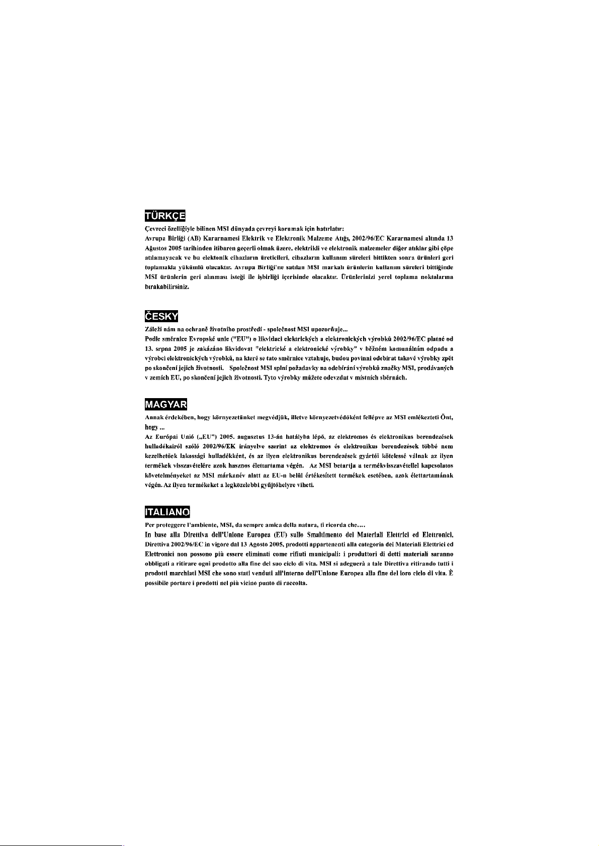
1394 GUID address
Label (optional)
MSI Reminds You...
1. Each board will be given a unique 1394 GUID from the
manufacturer’s default settings in the system BIOS.
2. Use the flash utility or Live Update from MSI’s website for BIOS
update. The 1394 GUID address is burnt in the BIOS core. If the 1394
GUID address is lost due to an unpredictable event, such as replacing a new BIOS chip, users can use the utility from MSI’s website by
entering the 1394 GUID address to recover its original one.
Page 15
PCI1
ALC655
J1394_1 (optional)
TA3
BIO
S
I
DE2ATX1FD
D1J
IR(op
tio
n
a
l)1
Winbond
W83627THF
Top : mouse
JPW1
SYSFAN1
RS480/RS482
JSP1(optional)
Bottom: keyboard
Top : Parallel Port
Bottom:
COM 1
VGA port
Top:1394 port(optional)
Buttom: USB ports
Top: LAN Jack
Bottom: USB
ports
Line-In
BATT
Line-Out
Mic
+
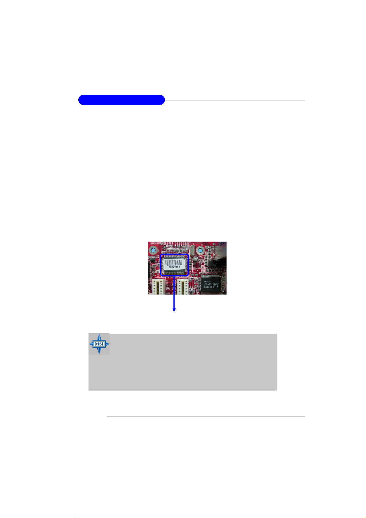
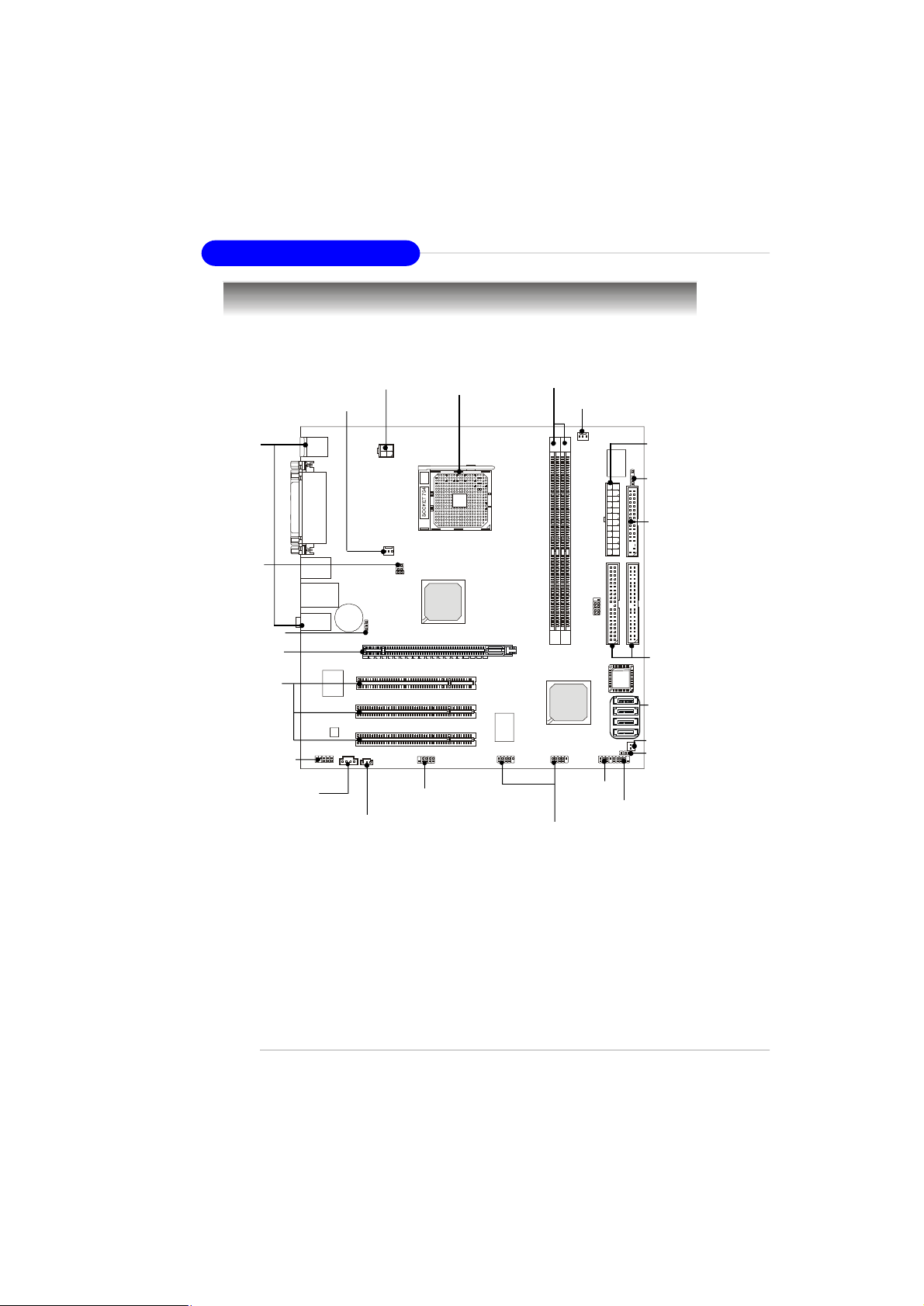
Mainboard Layout
JTV1
(optional)
JBAT1
PCIE16X1
ATI
Getting Started
CPUFAN1
1
2
R
R
D
D
D
D
JCOM2
(optional)
1
E
D
I
JAUDI01
JCD_IN1
PCI2
PCI3
VIA
VT6307
JUSB1
JUSB2
ATI
SB400
JBIOS_WP1
JFP2 JFP1
JCASE1
A
S
4
A
T
A
S
1
A
T
A
S
2
A
T
A
S
RS480M/ RS482M Series (MS-7145 v2.X) M-ATX Mainboard
1-5
Page 16
MS-7145 M-ATX Mainboard
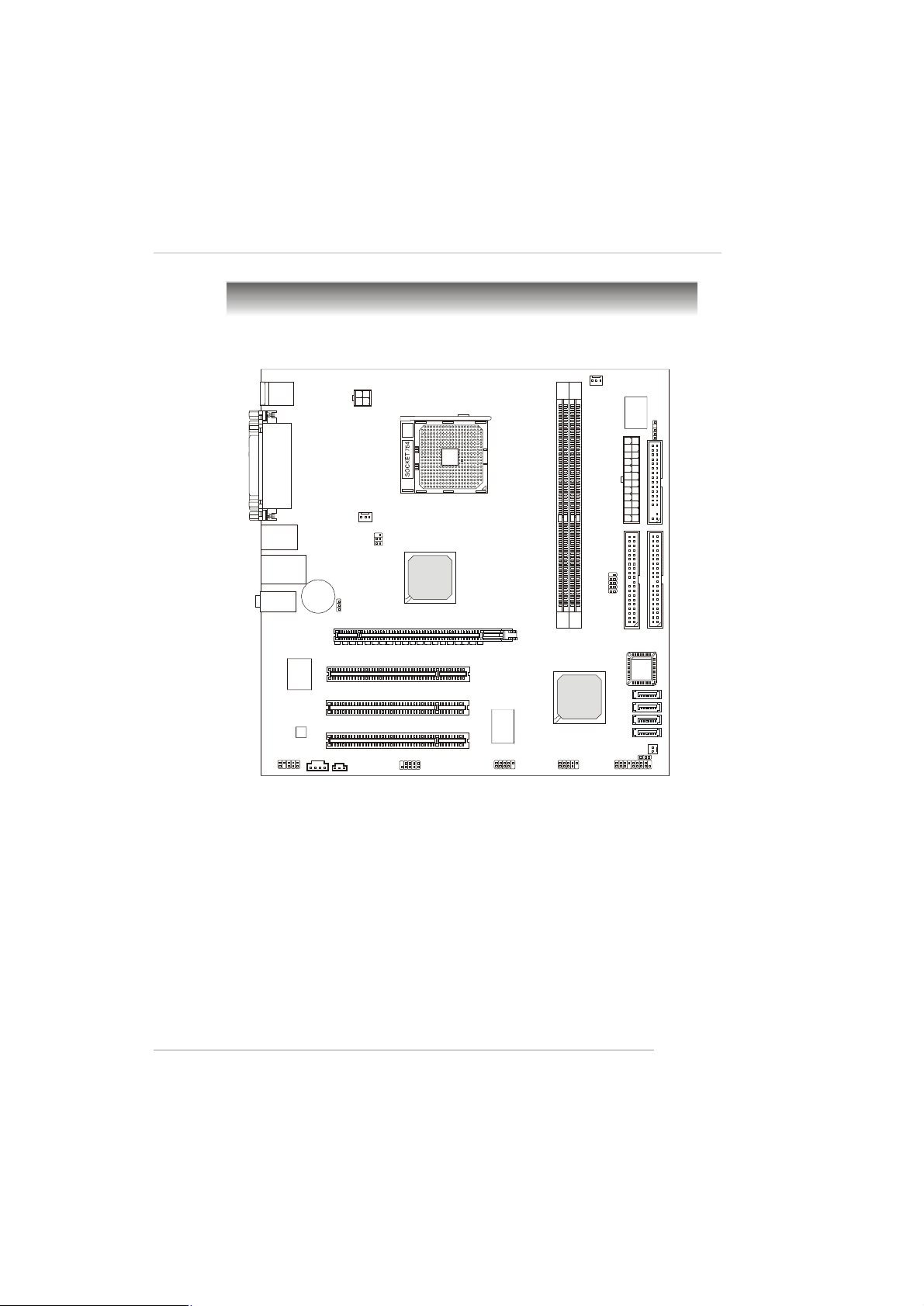
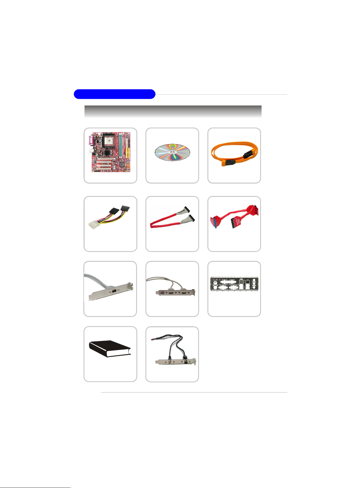
Packing Checklist
MSI motherboard
Power Cable
1394 Bracket (Optional)
MSI Driver/Utility CD
Round Cable of
Floppy Disk
USB Bracket (Optional)
SATA Cable (Optional)
Round Cable of
IDE Devices
Back IO Shield
1-6
User’ s Guide
TV-out Bracket
(Optional)
* The pictures are for
reference only and may
vary from the packing
contents of the product
you purchased.
Page 17
Getting Started
MSI Special Feature
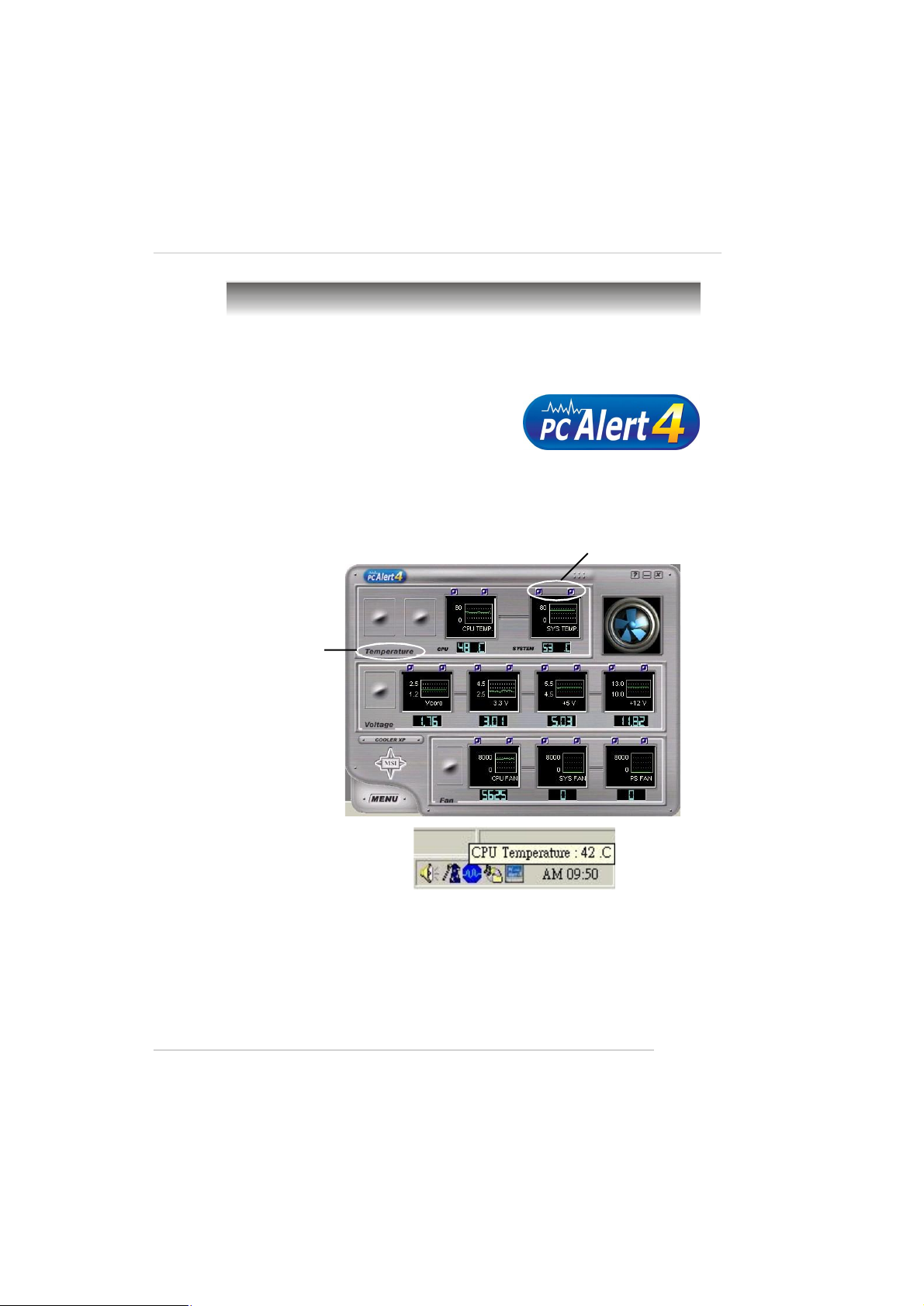
PC Alert™ 4
The PC AlertTM 4 is a utility you can find in the CD-ROM disk. The utility is just like
your PC doctor that can detect the following PC hardware status during real time
operation:
ö monitor CPU & system temperatures
ö monitor fan speeds
ö monitor system voltages
If one of the items above is abnormal, the program main screen will be immediately shown on the screen, with the abnormal item highlighted in red. This will
continue to be shown until the condition returns to the normal status.
Adjusting Keys
Temperature
Modes
Users can use the Adjusting Keys to change the minimum and maximum threshold
of each item for the system to send out a warning message. Click Temperature to
select the temperature modes of either Fahrenheit (oF) or Celsius (oC). The PC Alert™
4 icon on the Status Area will show the current CPU temperature.
1-7
Page 18
MS-7145 M-ATX Mainboard
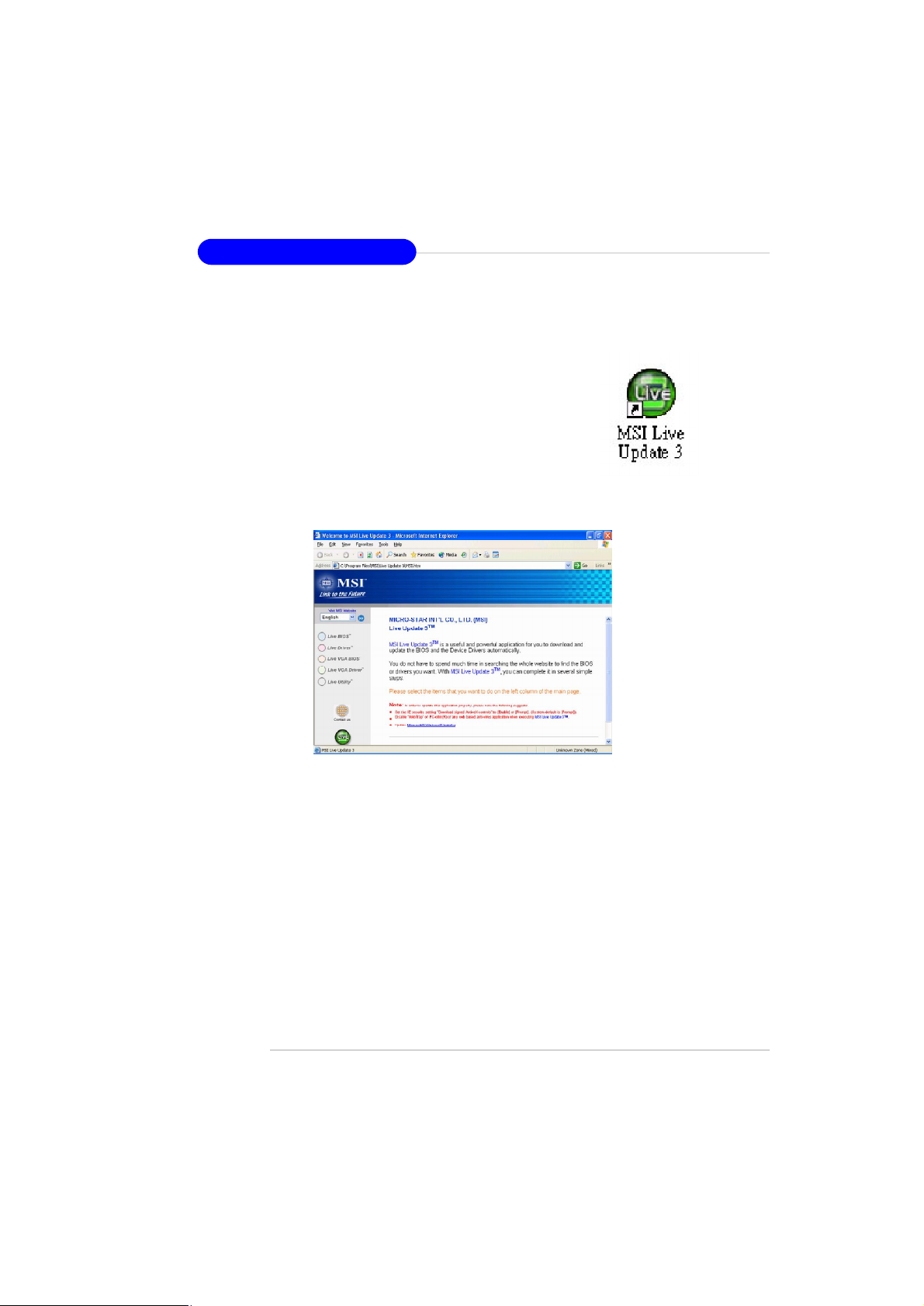
Live Update
The Live Update 3™ is a tool used to detect and update your
BIOS/drivers/VGA BIOS/VGA Driver/Utility online so that you
don’t need to search for the correct BIOS/driver version
throughout the whole Web site. To use the function, you need
to install the “MSI Live Update 3” application. After the
installation, the “ MSI Live Update 3” icon (as shown on the right)
will appear on the screen.
Double click the “ MSI Live Update 3” icon, and the following
screen will appear:
Several buttons are placed on the left column of the screen. Click the desired
button to start the update process.
Live BIOS – Updates the BIOS online.
Live Driver – Updates the drivers online.
Live VGA BIOS – Updates the VGA BIOS online.
Live VGA Driver – Updates the VGA driver online.
Live Utility – Updates the utilities online.
If the product you purchased does not support any of the functions listed above, a
“sorry” message is displayed. For more information on the update instructions,
insert the companion CD and refer to the “ Live Update Guide” under the “Manual”
Tab.
1-8
Page 19

Hardware Setup
Chapter 2. Hardware
Setup
Hardware Setup
This chapter tells you how to install the CPU, memory modules,
and expansion cards, as well as how to setup the jumpers on the
mainboard. Also, it provides the instructions on connecting the peripheral devices, such as the mouse, keyboard, etc.
While doing the installation, be careful in holding the components and follow the installation procedures.
2-1
Page 20
MS-7145 M-ATX Mainboard
W83627THF
Quick Components Guide
Back Panel
I/O, p.2-10
JTV1,
p.2-22
JBAT1, p.2-23
PCI Express
Slot, p.2-24
PCI Slots,
JAUDIO1,
p.2-18
JCD_IN1, p.2-19
p.2-24
JPW1, p.2-9
SYSFAN1,
p.2-15
JSP1, p.2-19
CPU, p.2-3
J1394_1, p.2-21
DDR DIMMs, p.2-7
CPUFAN1, p.2-15
JFP2,
p.2-20
JUSB1, JUSB2, p.2-20
ATX1, p.2-9
JIR1, p.2-19
FDD1, p.2-15
IDE1/2, p.2-16
SATA1~4,
p.2-13
JCASE1,p.2-21
JBIOS_WP1,
p.2-23
JFP1,
p.2-20
2-2
Page 21

Hardware Setup
Central Processing Unit: CPU
The mainboard supports AMD® Athlon64/ Sempron processor. The mainboard
uses a CPU socket called Socket-754 for easy CPU installation. When you are installing the CPU, make sure the CPU has a heat sink and a cooling fan attached on
the top to prevent overheating. If you do not have the heat sink and cooling fan,
contact your dealer to purchase and install them before turning on the computer.
For the latest information about CPU, please visit http://www.msi.com.tw/program/products/mainboard/mbd/pro_mbd_cpu_support.php.
MSI Reminds You...
Overheating
Overheating will seriously damage the CPU and system, always make
sure the cooling fan can work properly to protect the CPU from
overheating.
Replacing the CPU
While replacing the CPU, always turn off the ATX power supply or
unplug the power supply’s power cord from grounded outlet first to
ensure the safety of CPU.
2-3
Page 22
MS-7145 M-ATX Mainboard
Gold arrow
Gold arrow
Gold arrow
Correct CPU placement
Incorrect CPU placement
Close
Press down
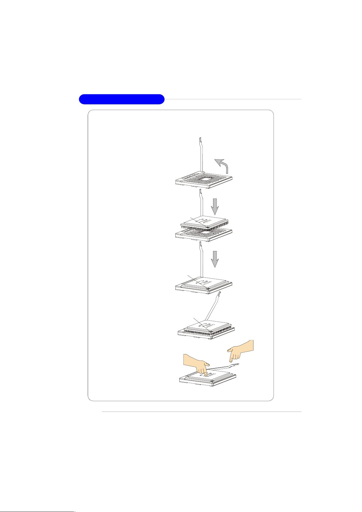
CPU Installation Procedures for Socket 754
1.Please turn off the power and
unplug the power cord before
installing the CPU.
Open Lever
2.Pull the lever sideways away
from the socket. Make sure to
raise the lever up to a 90-degree angle.
3.Look for the gold arrow of the
CPU. The gold arrow should point
as shown in the picture. The CPU
can only fit in the correct
orientation.
4.If the CPU is correctly installed,
the pins should be completely
embedded into the socket and
can not be seen. Please note
that any violation of the correct
installation procedures may
cause permanent damages to
your mainboard.
5. Press the CPU down firmly into
the socket and close the lever.
As the CPU is likely to move while
the lever is being closed, always close the lever with your
fingers pressing tightly on top of
the CPU to make sure the CPU is
properly and completely embedded into the socket.
Sliding
Plate
90 degree
O
X
the CPU
Lever
2-4
Page 23
Hardware Setup
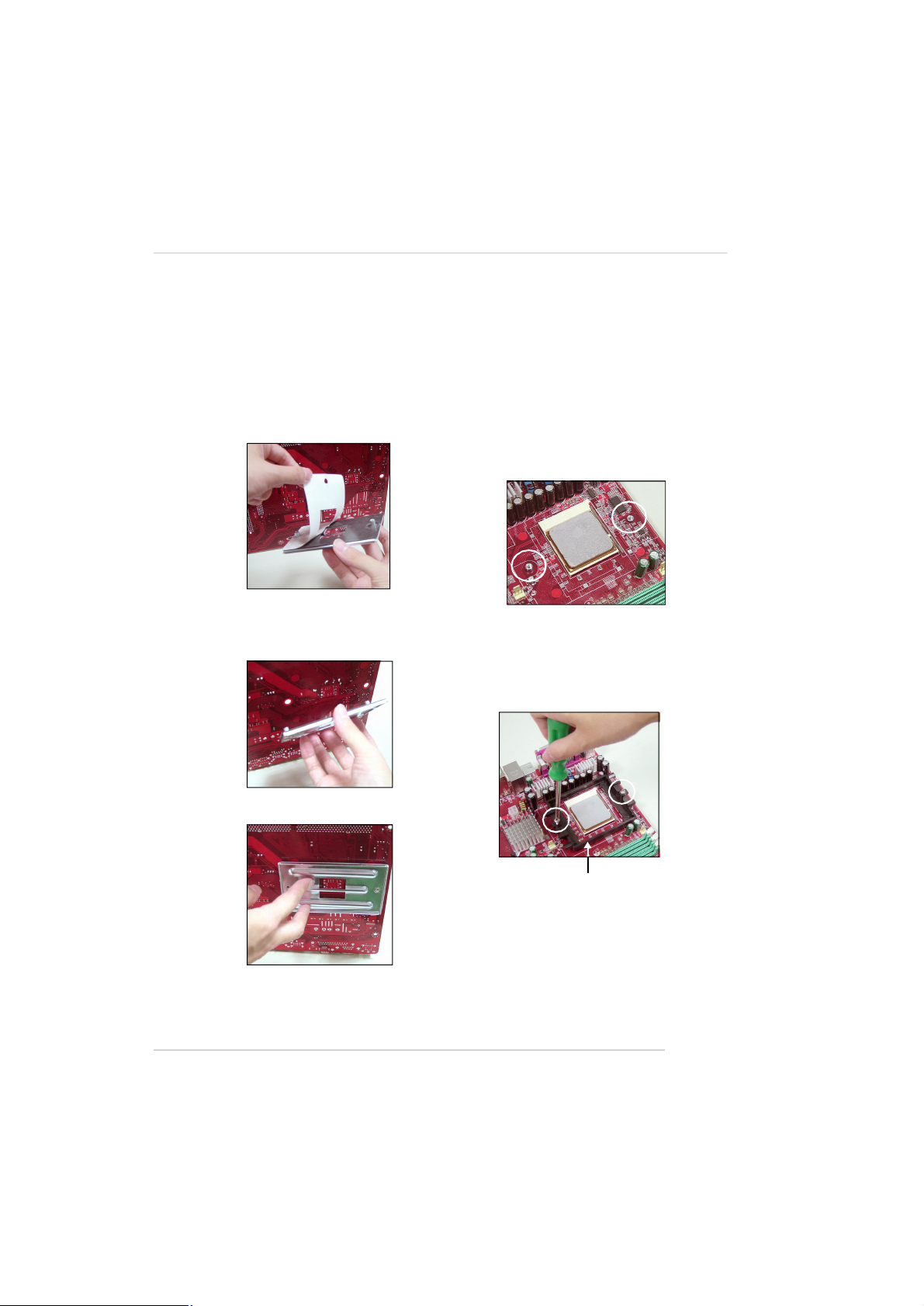
Installing AMD Athlon64 CPU Cooler Set
When you are installing the CPU, make sure the CPU has a heat sink and
a cooling fan attached on the top to prevent overheating. If you do not have
the heat sink and cooling fan, contact your dealer to purchase and install them before
turning on the computer.
1.Detach the shield of the
backplate’s paster.
2.Turn over the mainboard, and
install the backplate to the
proper position.
3.Turn over the mainboard
again and place the
mainboard on the flat surface.
Locate the two screw holes
of the mainboard.
4.Align the retention mechanism
and the backplate. Fix the retention mechanism and the
backplate with two screws.
retention mechanism
2-5
Page 24
MS-7145 M-ATX Mainboard
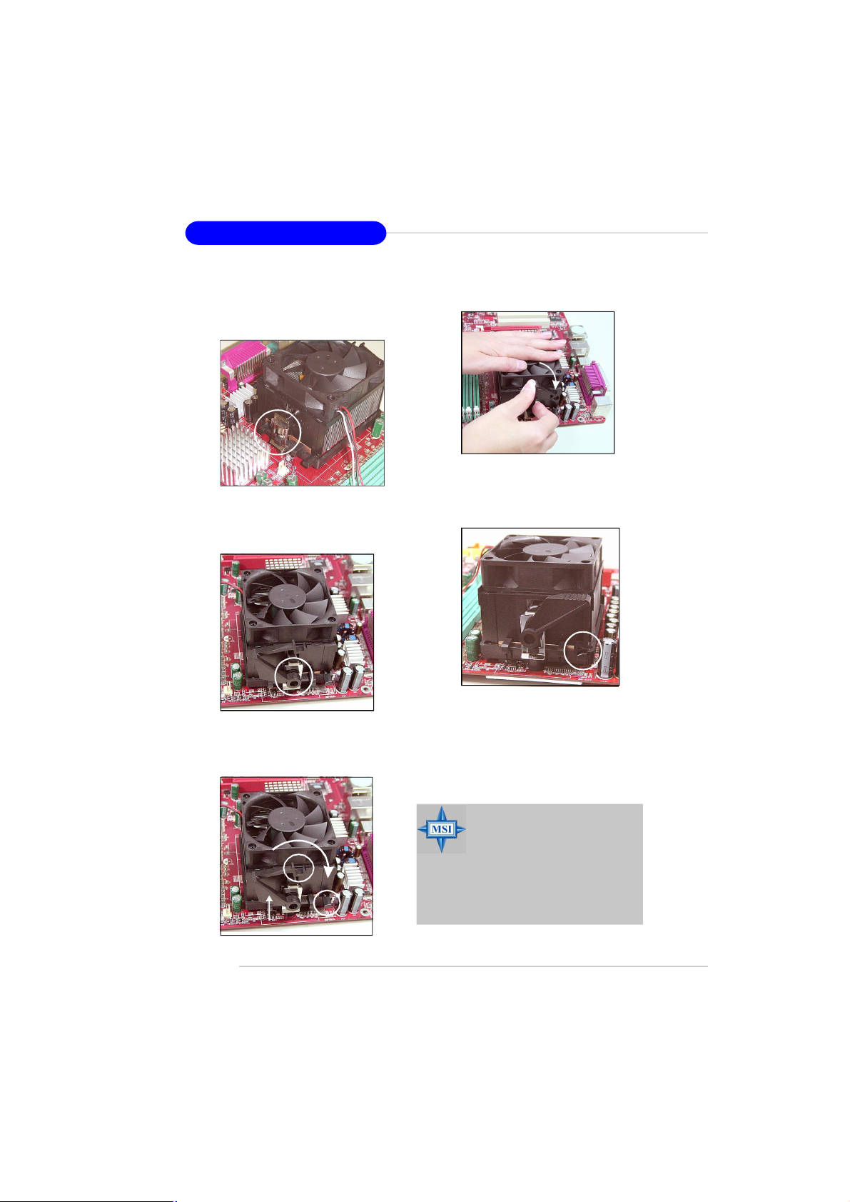
5.Position the cooling set onto the
retention mechanism. Hook one
end of the clip to hook first.
6.Press down the other end of the
clip to fasten the cooling set on
the top of the retention
mechanism.
8.Fasten down the lever.
9.Make sure the safety hook
completely clasps the fixed
bolt of the retention
mechanism.
7.Locate the Fix Lever, Safety Hook
and the Fixed Bolt. Lift up the intensive fixed lever.
Safety Hook
Fixed Lever
Fixed Bolt
2-6
MSI Reminds You...
While disconnecting the Safety
Hook from the fixed bolt, it is
necessary to keep an eye on
your fingers, because once the
Safety Hook is disconnected
from the fixed bolt, the fixed
lever will spring back instantly.
Page 25
Hardware Setup
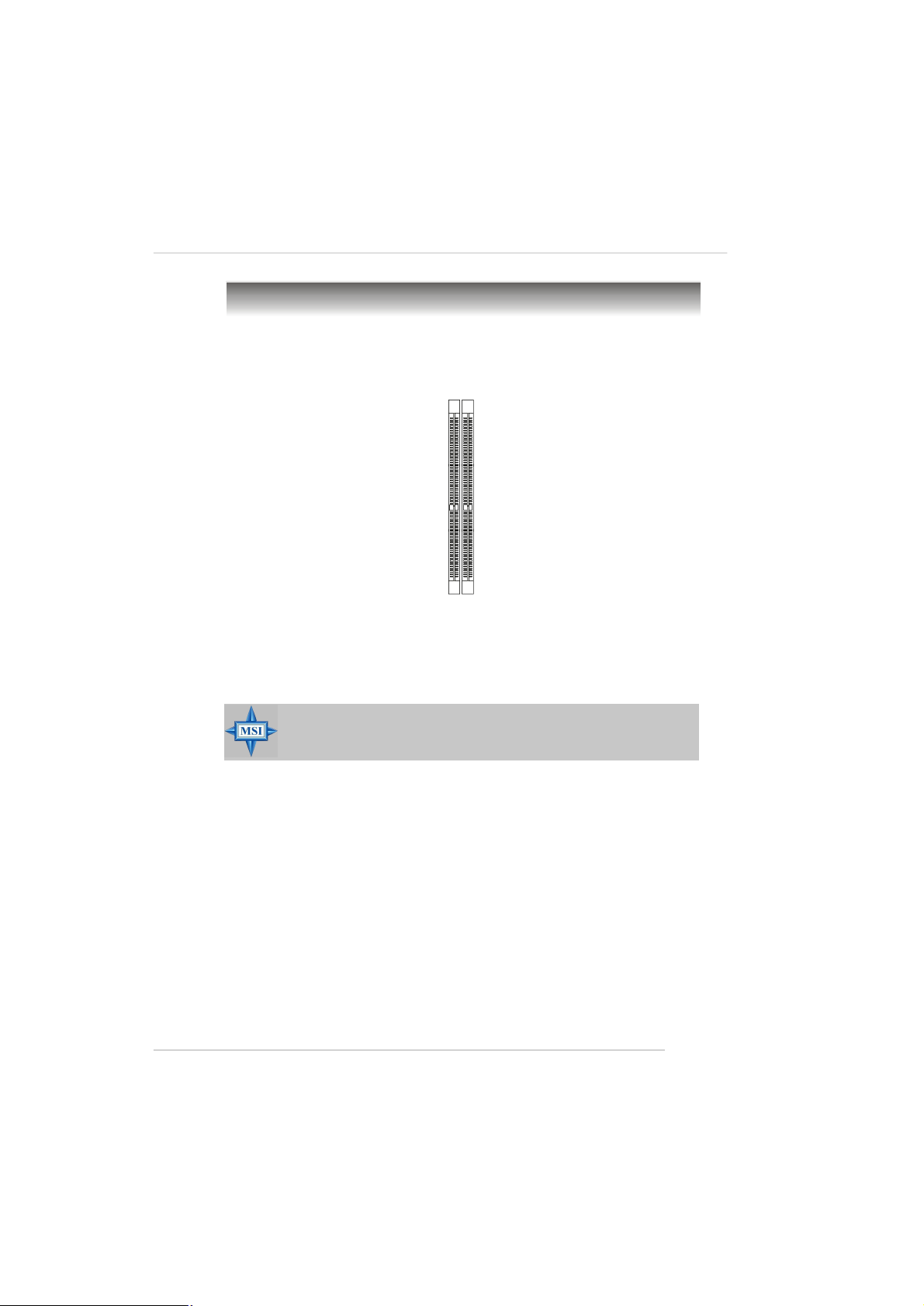
Memory
The mainboard provides 2 slots for 184-pin DDR DIMM (Double In-Line Memory
Module) modules and supports the memory size up to 2GB. You can install DDR 333/
400 modules on the DDR DIMM slots (DDR1/DDR2).
DDR1 DDR2
DIMM Module Combination
Install at least one DIMM module on the slots. Each DIMM slot supports up to a
maximum size of 1GB. Users can install either single- or double-sided modules to
meet their own needs.
MSI Reminds You...
- This mainboard DO NOT support the memory module installed
with more than 18 pieces of IC (integrated circuit).
2-7
Page 26
MS-7145 M-ATX Mainboard
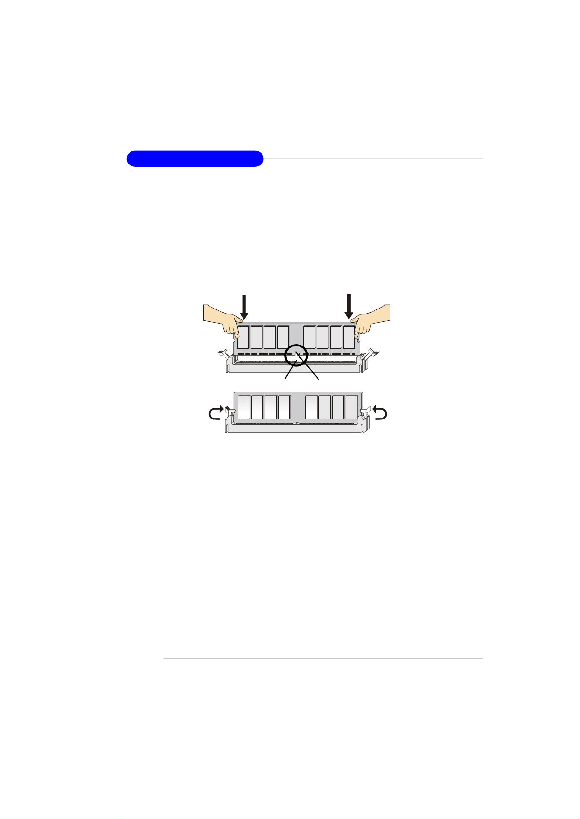
Installing DDR Modules
1. The DDR DIMM has only one notch on the center of module. The module will
only fit in the right orientation.
2. Insert the DIMM memory module vertically into the DIMM slot. Then push it in
until the golden finger on the memory module is deeply inserted in the socket.
3. The plastic clip at each side of the DIMM slot will automatically close.
2-8
Volt
Notch
Page 27
Hardware Setup
Power Supply
The mainboard supports ATX power supply for the power system. Before
inserting the power supply connector, always make sure that all components are
installed properly to ensure that no damage will be caused.
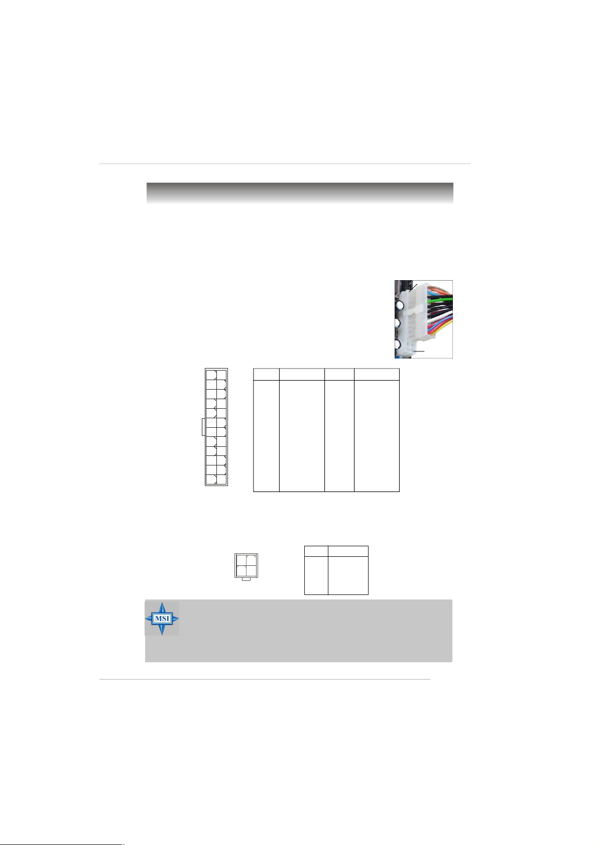
ATX 24-Pin Power Connector: ATX1
This connector allows you to connect an ATX 24-pin power supply. To connect the ATX 24-pin power supply, make sure the plug of the power
supply is inserted in the proper orientation and the pins are aligned.
Then push down the power supply firmly into the connector.
You may use the 20-pin ATX power supply as you like. If
you’d like to use the 20-pin ATX power supply, please plug your
power supply along with pin 1 & pin 13 (refer to the image at the
right hand). There is also a foolproof design on pin 11, 12, 23 & 24
to avoid wrong installation.
Pin Definition
13
ATX1
24
1
12
PIN SIGNAL
1 +3.3V
2 +3.3V
3 GND
4 +5V
5 GND
6 +5V
7 GND
8 PWR OK
9 5VSB
10 +12V
11 +12V
12 +3.3V
PIN SIGNAL
13 +3.3V
14 -12V
15 GND
16 PS-ON#
17 GND
18 GND
19 GND
20 Res
21 +5V
22 +5V
23 +5V
24 GND
pin 13
pin 12
ATX 12V Power Connector: JPW1
This 12V power connector is used to provide power to the CPU.
JPW1
2
1
34
MSI Reminds You...
1. These two connectors connect to the ATX power supply and have to
work together to ensure stable operation of the mainboard.
2. Power supply of 350 watts (and above) is highly recommended for
system stability.
3. ATX 12V power connection should be greater than 18A.
Pin Definition
PIN SIGNAL
1 GND
2 GND
3 12V
4 12V
2-9
Page 28
MS-7145 M-ATX Mainboard
Mouse
Parallel
Back Panel
(optional)
1394 Port
L-In
LAN
Keyboard
COM Port
VGA Port
USB Ports
L-Out
Mic
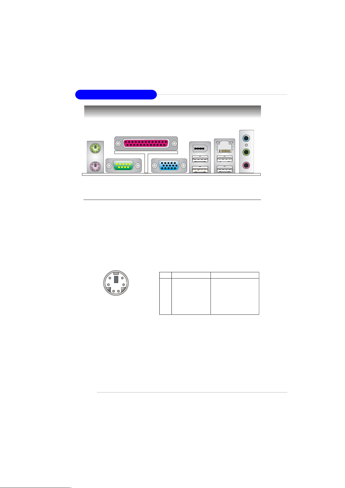
Mouse/Keyboard Connector
The mainboard provides a standard PS/2® mouse/keyboard mini DIN connector for attaching a PS/2® mouse/keyboard. You can plug a PS/2® mouse/keyboard
directly into this connector. The connector location and pin assignments are as
follows:
Pin Definition
6
4
2
PS/2 Mouse / Keyboard
(6-pin Female)
5
3
1
PIN SIGNAL DESCRIPTION
1 Mouse/Keyboard Data Mouse/Keyboard data
2 NC No connection
3 GND Ground
4 VCC +5V
5 Mouse/Keyboard Clock Mouse/Keyboard clock
6 NC No connection
2-10
Page 29
Hardware Setup
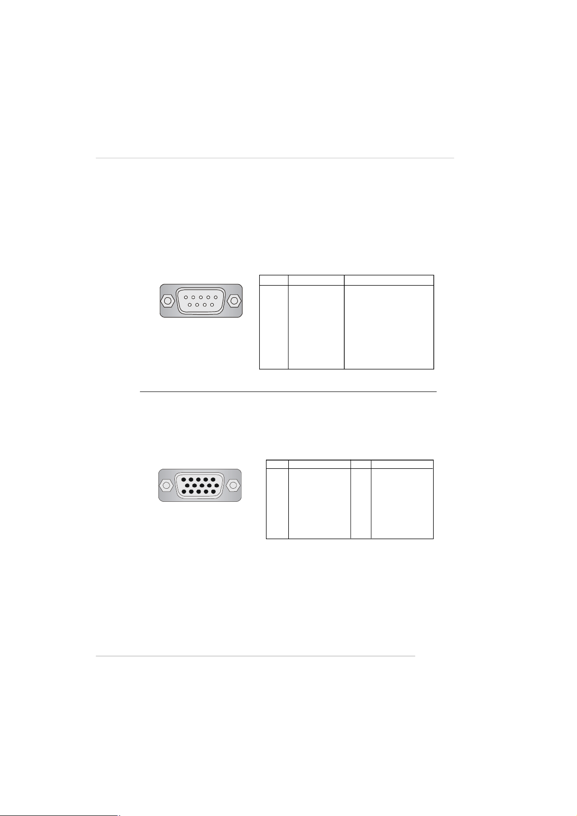
Serial Port Connector
The mainboard offers one 9-pin male DIN connector as the serial port. The port
is a 16550A high speed communication port that sends/receives 16 bytes FIFOs. You
can attach a serial mouse or other serial devices directly to the connector.
Pin Definition
1 2 3 4 5
6 7 8 9
9-Pin Male DIN Connector
PIN SIGNAL DESCRIPTION
1 DCD Data Carry Detect
2 SIN Serial In or Receive Data
3 SOUT Serial Out or Transmit Data
4 DTR Data Terminal Ready)
5 GND Ground
6 DSR Data Set Ready
7 RTS Request To Send
8 CTS Clear To Send
9 RI Ring Indicate
VGA Connector
The mainboard provides a DB 15-pin female connector to connect a VGA
monitor.
5
15
1
11
VGA Connector
(DB 15-pin)
Pin Definition
Pin Signal Description Pin Signal Description
1 RED 2 GREEN
3 BLUE 4 N/C
5 GND 6 GND
7 GND 8 GND
9 +5V 10 GND
11 N/C 12 SDA
13 Horizontal Sync 14 Vertical Sync
15 SCL
2-11
Page 30
MS-7145 M-ATX Mainboard
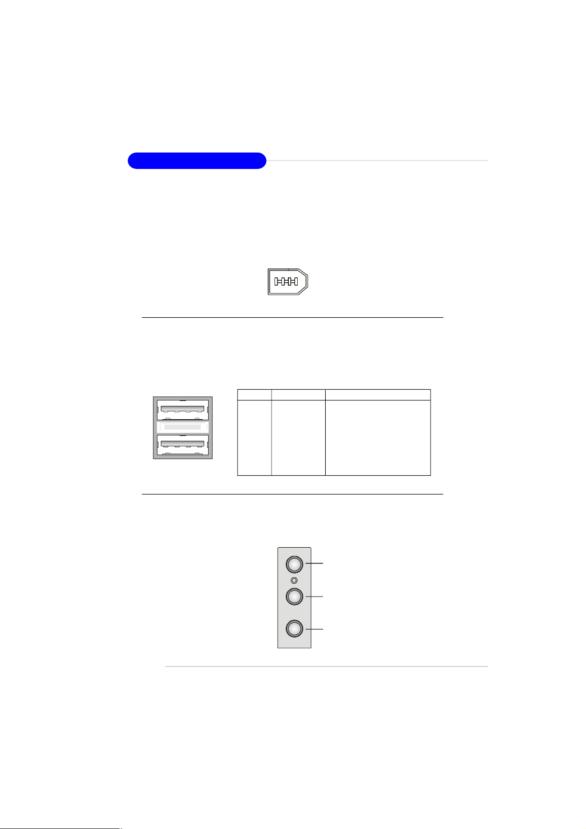
IEEE 1394 Port (Optional)
The back panel provides one standard IEEE 1394 port. The standard IEEE1394
port connects to IEEE1394 devices without external power. The IEEE1394 highspeed serial bus complements USB by providing enhanced PC connectivity for a
wide range of devices, including consumer electronics audio/video (A/V) appliances,
storage peripherals, other PCs, and portable devices.
IEEE1394 Port
USB Connectors
The mainboard provides an OHCI (Open Host Controller Interface) Universal
Serial Bus root for attaching USB devices such as keyboard, mouse or other USBcompatible devices. You can plug the USB device directly into the connector.
USB Port Definition
1 2 3 4
5 6 7 8
USB Ports
PIN SIGNAL DESCRIPTION
1 VCC +5V
2 -Data 0 Negative Data Channel 0
3 +Data0 Positive Data Channel 0
4 GND Ground
5 VCC +5V
6 -Data 1 Negative Data Channel 1
7 +Data 1 Positive Data Channel 1
8 GND Ground
Audio Port Connectors
Line Out is a connector for Speakers or Headphones. Line In is used for
external CD player, Tape player, or other audio devices. Mic is a connector for
microphones.
Line In
Line Out
MIC
2-12
Page 31

Hardware Setup
RJ-45 LAN Jack: 10/100 LAN (8100C) /Giga-bit LAN (8110S) (Optional)
The mainboard provides two standard RJ-45 jacks for connection to Local
Area Network (LAN). Giga-bit LAN enables data to be transferred at 1000, 100 or
10Mbps. You can connect a network cable to either LAN jack.
Activity Indicator
Link Indicator
8 1
RJ-45 LAN Jack
LED Color LED State Condition
Left Orange On (steady state) LAN link is established.
Right On 100 Mbit/sec data rate is selected.
Off LAN link is not established.
On (brighter & pulsing) The computer is communicating with another
computer on the LAN.
Green Off 10 Mbit/sec data rate is selected.
Orange On 1000 Mbit/sec data rate is selected.
The pin assignments vary depending on the transfer rates: 10/100Mbps or
1000Mbps. Note that Pin 1/2, 3/6, 4/5, 7/8 must work in pairs. Please refer
to the following for details:
10/100 LAN Pin Definition Giga-bit LAN Pin Definition
PIN SIGNAL DESCRIPTION
1 TDP Transmit Differential Pair
2 TDN Transmit Differential Pair
3 RDP Receive Differential Pair
4 NC Not Used
5 NC Not Used
6 RDN Receive Differential Pair
7 NC Not Used
8 NC Not Used
PIN SIGNAL DESCRIPTION
1 D0P Differential Pair 0+
2 D0N Differential Pair 0 3 D1P Differential Pair 1+
4 D2P Differential Pair 2+
5 D2N Differential Pair 2 6 D1N Differential Pair 1 7 D3P Differential Pair 3+
8 D3N Differential Pair 3-
2-13
Page 32

MS-7145 M-ATX Mainboard
Parallel Port Connector: LPT1
The mainboard provides a 25-pin female centronic connector as LPT. A
parallel port is a standard printer port that supports Enhanced Parallel Port (EPP) and
Extended Capabilities Parallel Port (ECP) mode.
13 1
25
14
Pin Definition
PIN SIGNAL DESCRIPTION
1 STROBE Strobe
2 DATA0 Data0
3 DATA1 Data1
4 DATA2 Data2
5 DATA3 Data3
6 DATA4 Data4
7 DATA5 Data5
8 DATA6 Data6
9 DATA7 Data7
10 ACK# Acknowledge
11 BUSY Busy
12 PE Paper End
13 SELECT Select
14 AUTO FEED# Automatic Feed
15 ERR# Error
16 INIT# Initialize Printer
17 SLIN# Select In
18 GND Ground
19 GND Ground
20 GND Ground
21 GND Ground
22 GND Ground
23 GND Ground
24 GND Ground
25 GND Ground
2-14
Page 33

Hardware Setup
Connectors
Floppy Disk Drive Connector: FDD1
The mainboard provides a standard floppy disk drive connector that supports
360K, 720K, 1.2M, 1.44M and 2.88M floppy disk types.
FDD1
Fan Power Connectors: CPUFAN1 / SYSFAN1
The fan power connectors support system cooling fan with +12V. When
connecting the wire to the connectors, always take note that the red wire is the
positive and should be connected to the +12V, the black wire is Ground and should
be connected to GND. If the mainboard has a System Hardware Monitor chipset onboard, you must use a specially designed fan with speed sensor to take advantage
of the CPU fan control.
SENSOR
CPUFAN1
+12V
GND
SENSOR
+12V
GND
SYSFAN1
MSI Reminds You...
Please refer to the recommended CPU fans at AMD® official website
or consult the vendors for proper CPU cooling fan.
2-15
Page 34

MS-7145 M-ATX Mainboard
ATA133 Hard Disk Connectors: IDE1 & IDE2
The mainboard has a 32-bit Enhanced PCI IDE and Ultra DMA 66/100/133 controller that provides PIO mode 0~4, Bus Master, and Ultra DMA 66/100/133 function.
You can connect up to four hard disk drives, CD-ROM and other IDE devices.
The Ultra ATA133 interface boosts data transfer rates between the computer
and the hard drive up to 133 megabytes (MB) per second. The new interface is onethird faster than earlier record-breaking Ultra ATA/100 technology and is backwards
compatible with the existing Ultra ATA interface.
IDE1IDE2
IDE1 (Primary IDE Connector)
The first hard drive should always be connected to IDE1. IDE1 can connect a Master
and a Slave drive. You must configure second hard drive to Slave mode by setting the
jumper accordingly.
IDE2 (Secondary IDE Connector)
IDE2 can also connect a Master and a Slave drive.
MSI Reminds You...
If you install two hard disks on cable, you must configure the second
drive to Slave mode by setting its jumper. Refer to the hard disk documentation supplied by hard disk vendors for jumper setting instructions.
2-16
Page 35

Hardware Setup
Serial ATA Connectors: SATA1~SATA4
The ATI SB400 SouthBridge supports four serial ATA connectors SATA1~SATA4.
SATA1~SATA4 are high-speed Serial ATA interface ports. Each supports 1st generation serial ATA data rates of 150MB/s and is fully compliant with Serial ATA 1.0
specifications. Each Serial ATA connector can connect to 1 hard disk device. The ATI
SB400 also supports SATA RAID 0 or SATA RAID 1.
SATA3
SATA4
SATA1
SATA1~ SATA4 Pin Definition
PIN SIGNAL PIN SIGNAL
1 GND 2 RXP
3 RXN 4 GND
5 TXN 6 TXP
7 GND
SATA2
71
Serial ATA cable
Take out the dust cover and
connect to the hard disk
devices
Connect to SATA1/2/3/4
MSI Reminds You...
Please do not fold the Serial ATA cable into 90-degree angle. Otherwise,
data loss may occur during transmission.
2-17
Page 36

MS-7145 M-ATX Mainboard
Serial Port Header: JCOM2 (Optional)
The mainboard offers one 9-pin header as serial port. The port is a 16550A
high speed communication port that sends/receives 16 bytes FIFOs. You can attach
a serial mouse or other serial device directly to it.
Pin Definition
JCOM2
9
6
5
1
PIN SIGNAL DESCRIPTION
1 DCD Data Carry Detect
2 SIN Serial In or Receive Data
3 SOUT Serial Out or Transmit Data
4 DTR Data Terminal Ready)
5 GND Ground
6 DSR Data Set Ready
7 RTS Request To Send
8 CTS Clear To Send
9 RI Ring Indicate
Front Panel Audio Connector: JAUDIO1
The JAUD1 front panel audio connector allows you to connect to the front
panel audio and is compliant with Intel® Front Panel I/O Connectivity Design Guide.
JAUDIO1
9
10
Pin Definition
PIN SIGNAL DESCRIPTION
1 AUD_MIC Front panel microphone input signal
2 AUD_GND Ground used by analog audio circuits
3 AUD_MIC_BIAS Microphone power
4 AUD_VCC Filtered +5V used by analog audio circuits
5 AUD_FPOUT_R Right channel audio signal to front panel
6 AUD_RET_R Right channel audio signal return from front panel
7 HP_ON Reserved for future use to control headphone amplifier
8 KEY No pin
9 AUD_FPOUT_L Left channel audio signal to front panel
10 AUD_RET_L Left channel audio signal return from front panel
1
2
2-18
MSI Reminds You...
If you don’t want to connect to the front audio header,
pins 5 & 6, 9 & 10 have to be jumpered in order to have
signal output directed to the rear audio ports. Otherwise,
the Line-Out connector on the back panel will not
function.
9
5
10
6
Page 37

Hardware Setup
CD-In Connector: JCD_IN1
This connector is provided for CD-ROM audio.
JCD_IN1
L
R
GND
SPDIF-Out Connector: JSP1 (Optional)
This connector is used to connect SPDIF (Sony & Philips Digital Interconnect
Format) interface for digital audio transmission.
VCC
SPDIF
Connected to JSP1
GND
JSP1
SPDIF Bracket (Optional)
IrDA Infrared Module Header: JIR1 (Optional)
The connector allows you to connect to IrDA Infrared module. You must configure the setting through the BIOS setup to use the IR function.
JIR1 Pin Definition
JIR1
1
Pin Signal
1 VCC5
2 NC
3 IRRX
4 GND
5 IRTX
2-19
Page 38

MS-7145 M-ATX Mainboard
Front Panel Connectors: JFP1/ JFP2
The mainboard provides two front panel connectors for electrical connection
to the front panel switches and LEDs. JFP1 is compliant with Intel® Front Panel I/O
Connectivity Design Guide.
JFP1 Pin Definition
PIN SIGNAL DESCRIPTION
1 HD_LED_P Hard disk LED pull-up
2 FP PWR/SLP MSG LED pull-up
3 HD_LED_N Hard disk active LED
4 FP PWR/SLP MSG LED pull-up
10
5 RST_SW_N Reset Switch low reference pull-down to GND
9
6 PWR_SW_P Power Switch high reference pull-up
7 RST_SW_P Reset Switch high reference pull-up
8 PWR_SW_N Power Switch low reference pull-down to GND
9 RSVD_DNU Reserved. Do not use.
JFP1
Power
Power
Switch
LED
2
1
Reset
HDD
Switch
LED
JFP2 Pin Definition
PIN SIGNAL PIN SIGNAL
1 GND 2 SPK3 SLED 4 NC
5 PLED 6 NC
7 NC 8 SPK+
JFP2
2
1
Speaker
Power
LED
8
7
Front USB Connectors: JUSB1 / JUSB2
The mainboard provides two standard USB 2.0 pin headers JUSB1 & JUSB2 .
USB 2.0 technology increases data transfer rate up to a maximum throughput of
480Mbps, which is 40 times faster than USB 1.1, and is ideal for connecting highspeed USB interface peripherals such as USB HDD, digital cameras, MP3 players,
printers, modems and the like.
2 10
1
JUSB1, JUSB2
Connected to JUSB1 or JUSB2
9
(USB 2.0)
JUSB1 & JUSB2 Pin Definition
PIN SIGNAL PIN SIGNAL
1 VCC 2 VCC
3 USB0- 4 USB15 USB0+ 6 USB1+
7 GND 8 GND
9 Key (no pin) 10 USBOC
USB 2.0 Bracket
(Optional)
2-20
Page 39

Hardware Setup
MSI Reminds You...
Note that the pins of VCC and GND must be connected correctly to
avoid possible damage.
IEEE 1394 Connectors: J1394_1 (Optional)
The mainboard provides one 1394 pin header that allows you to connect IEEE
1394 ports via an external IEEE1394 bracket (optional).
Pin Definition
9
10
J1394_1
Connected to J1394_1
1
2
PIN SIGNAL PIN SIGNAL
1 TPA+ 2 TPA3 Ground 4 Ground
5 TPB+ 6 TPB7 Cable power 8 Cable power
9 Key (no pin) 10 Ground
IEEE1394 Bracket (Optional)
Foolproof
design
Chassis Intrusion Switch Connector: JCASE1
This connector is connected to a 2-pin chassis switch. If the
chassis is opened, the switch will be short. The system will record
this status and show a warning message on the screen. To clear
the warning, you must enter the BIOS utility and clear the record.
GND
CINTRU
JCASE1
2
1
2-21
Page 40

MS-7145 M-ATX Mainboard
TV-Out Connector: JTV1 (Optional)
The mainboard optionally provides a TV-Out connector for you to attach a TVOut bracket. The TV-Out bracket offers two types of TV-Out connectors: S-Video
and RCA Composite connector. Select the appropriate one to connect to the television and the television will be able to display PC’s information.
TV-Out Bracket
3
5
2
1
4
JTV1
TV-Out Connector
(S-Video)
JTV1 Pin Definition
Pin Description Pin Description
1 GND 4 COMP
2 Y 5 GND
3 C
TV-Out Connector
(RCA Composite)
2-22
Page 41

Hardware Setup
Jumpers
The motherboard provides the following jumper for you to set the computer’s
function. This section will explain how to change your motherboard’s function through
the use of jumpers.
Clear CMOS Jumper: JBAT1
There is a CMOS RAM on board that has a power supply from external battery
to keep the system configuration data. With the CMOS RAM, the system can automatically boot OS every time it is turned on. If you want to clear the system configuration,
use the JBAT1 (Clear CMOS Jumper ) to clear data. Follow the instructions below to
clear the data:
1
JBAT1
1
3
Keep Data
1
3
Clear Data
MSI Reminds You...
You can clear CMOS by shorting 2-3 pin while the system is off.
Then return to 1-2 pin position. Avoid clearing the CMOS while the
system is on; it will damage the mainboard.
BIOS Writh Protect Jumper: JBIOS_WP1 (Optional)
This jumper is used to lock or unlock the boot block area on BIOS. When
unlocked, the BIOS boot block area can be updated. When locked, the BIOS boot
block area cannot be updated.
1
JBIOS_WP1
31 3
Unlocked
(Enable BIOS Flash)
1
Locked
(Disable BIOS Flash)
2-23
Page 42

MS-7145 M-ATX Mainboard
Slots
The motherboard provides one PCI Express x16 slot and three 32-bit PCI bus
slots.
PCI Express Slots
The PCI Express slot, as a high-bandwidth, low pin count, serial, interconnect
technology, supports Intel highest performance desktop platforms utilizing the Intel
Pentium 4 processor with HT Technology.
PCI Express architecture provides a high performance I/O infrastructure for
Desktop Platforms with transfer rates starting at 2.5 Giga transfers per second over
a PCI Express x1 lane for Gigabit Ethernet, TV Tuners, 1394 controllers, and general
purpose I/O. Also, desktop platforms with PCI Express Architecture will be designed
to deliver highest performance in video, graphics, multimedia and other sophisticated
applications. Moreover, PCI Express architecture provides a high performance graphics
infrastructure for Desktop Platforms doubling the capability of existing AGP8x designs with transfer rates of 4.0 GB/s over a PCI Express x16 lane for graphics
controllers.
You can insert the expansion cards to meet your needs. When adding or
removing expansion cards, make sure that you unplug the power supply first.
PCI Express x16 slot
PCI (Peripheral Component Interconnect) Slots
The PCI slots allow you to insert the expansion cards to meet your needs.
When adding or removing expansion cards, make sure that you unplug the power
supply first. Meanwhile, read the documentation for the expansion card to make any
necessary hardware or software settings for the expansion card, such as jumpers,
switches or BIOS configuration.
PCI Slots
PCI Interrupt Request Routing
The IRQ, acronym of interrupt request line and pronounced I-R-Q, are hardware lines over which devices can send interrupt signals to the microprocessor. The
PCI IRQ pins are typically connected to the PCI bus pins as follows:
Order 1 Order 2 Order 3 Order 4
PCI Slot 1 INT E# INT F# INT G# INT H#
PCI Slot 2 INT F# INT G# INT H# INT E#
PCI Slot 3 INT G# INT H# INT E# INT F#
2-24
Page 43

BIOS Setup
Chapter 3. BIOS Setup
BIOS Setup
This chapter provides information on the BIOS Setup program and
allows you to configure the system for optimum use.
You may need to run the Setup program when:
² An error message appears on the screen during the sys-
tem booting up, and requests you to run SETUP.
² You want to change the default settings for customized
features.
MSI Reminds You...
1. The items under each BIOS category described in this chapter are
under continuous update for better system performance.
Therefore, the description may be slightly different from the latest
BIOS and should be held for reference only.
2. While booting up, the BIOS version is shown in the 1st line appearing after the memory counting. It is usually in the format:
example: A7145AMS V1.0 032405
where:
1st digit refers to BIOS maker as A=AMI(R); W=AWARD(R)
2nd - 5th digit refers to the model number.
6th digit refers to the ATi chipset,
MS=all standard customers.
V1.0 refers to the BIOS version.
032405 refers to the date this BIOS is released.
3-1
Page 44

MS-7145 M-ATX Mainboard
Entering Setup
Power on the computer and the system will start POST (Power On Self Test) process.
When the message below appears on the screen, press <DEL> key to enter Setup.
DEL: Setup Menu TAB: Logo F11: Boot Menu
If the message disappears before you respond and you still wish to enter Setup,
restart the system by turning it OFF and On or pressing the RESET button. You may
also restart the system by simultaneously pressing <Ctrl>, <Alt>, and <Delete> keys.
Selecting the First Boot Device
You are allowed to select the 1st boot device without entering the BIOS setup utility
by pressing <F11>. When the same message as listed above appears on the screen,
press <F11> to trigger the boot menu.
The POST messages might pass by too quickly for you to respond in time. If so,
restart the system and press <F11> after around 2 or 3 seconds to activate the boot
menu similar to the following.
Select First Boot Device
Floppy : 1st Floppy
IDE-0 : IBM-DTLA-307038
CDROM : ATAPI CD-ROM DRIVE 40X M
[Up/Dn] Select [RETURN] Boot [ESC] cancel
The boot menu will list all the bootable devices. Select the one you want to boot from
by using arrow keys and then pressing <Enter>. The system will boot from the
selected device. The selection will not make changes to the settings in the BIOS setup
utility, so next time when you power on the system, it will still use the original first
boot device to boot up.
3-2
Page 45

BIOS Setup
Control Keys
<↑> Move to the previous item
<↓> Move to the next item
<←> Move to the item in the left hand
<→> Move to the item in the right hand
<Enter> Select the item
<Esc> Jumps to the Exit menu or returns to the main menu from a
submenu
<+> Increase the numeric value or make changes
<-> Decrease the numeric value or make changes
<F6> Load Optimized Defaults
<F7> Load Fail-Safe Defaults
<F10> Save all the CMOS changes and exit
Getting Help
After entering the Setup utility, the first screen you see is the Main Menu.
Main Menu
The main menu displays the setup categories the BIOS supplies. You can use the
arrow keys to select the item. The on-line description for the selected setup category
is displayed at the bottom of the screen.
Default Settings
The preset Optimal Defaults of the BIOS setup program provide optimal performance
settings for all devices and the system.
MSI Reminds You...
The items under each BIOS category described in this chapter are
under continuous update for better system performance. Therefore, the
description may be slightly different from the latest BIOS and should be
held for reference only.
3-3
Page 46

MS-7145 M-ATX Mainboard
The Main Menu
Once you enter AMIBIOS CMOS SETUP UTILITY, the Main Menu will appear on the
screen. Use arrow keys to move among the items and press <Enter> to enter the
sub-menu.
Standard CMOS Features
Use this menu for basic system configurations, such as time, date etc.
Advanced BIOS Features
Use this menu to setup the items of AWARD® special enhanced features.
Advanced Chipset Features
Use this menu to change the values in the chipset registers and optimize your system’s performance.
Integrated Peripherals
Use this menu to specify your settings for integrated peripherals.
Power Management Setup
Use this menu to specify your settings for power management.
PNP/PCI Configurations
This entry appears if your system supports PnP/PCI.
H/W Monitor
This entry shows your PC health status.
Cell Menu
This menu shows the frequency of CPU.
3-4
Page 47

BIOS Setup
Load Fail-Safe Defaults
Use this menu to load the default values set by the BIOS vendor for stable system
performance.
Load Optimized Defaults
Use this menu to load the default values set by the mainboard manufacturer specifically for optimal performance of the mainboard.
BIOS Setting Password
Use this menu to set the password for BIOS.
Save & Exit Setup
Save changes to CMOS and exit setup.
Exit Without Saving
Abandon all changes and exit setup.
3-5
Page 48

MS-7145 M-ATX Mainboard
Standard CMOS Features
The items in Standard CMOS Features Menu includes some basic setup items.
Use the arrow keys to highlight the item and then use the <PgUp> or <PgDn> keys to
select the value you want in each item.
Date (MM:DD:YY)
This allows you to set the system to the date that you want (usually the current date).
The format is <day><month> <date> <year>.
day Day of the week, from Sun to Sat, determined by
month The month from Jan. through Dec.
date The date from 1 to 31 can be keyed by numeric
year The year can be adjusted by users.
BIOS. Read-only.
function keys.
Time(HH:MM:SS)
This allows you to set the system time that you want (usually the current time). The
time format is <hour> <minute> <second>.
Primary/Secondary IDE Master/Slave (for IDE Devices)
Third/Fourth/Fifth/Sixth IDE Master (for SATA Devices)
Press <+> or <-> to select the hard disk drive type. The specification of hard disk
drive will show up on the right hand according to your selection. Press <Enter> for
the sub-menu of each item:
3-6
Page 49

BIOS Setup
Device
This item shows the information about the specified item. Read-only.
LBA/Large Mode
This item allows you to enable or disable the LBA (Logical Block Address, the
logical block size in hard disk) mode. Setting options: [Auto], [Disabled].
DMA Mode
This item allows you to enable or disable the DMA (Direct Memory Access) mode.
Setting options: [Auto], [Disabled], [UDMA0], [UDMA1], [UDMA2], [UDMA3],
[UDMA4], [UDMA5].
Hard Disk S.M.A.R.T.
This allows you to activate the S.M.A.R.T. (Self-Monitoring Analysis & Reporting
Technology) capability for the hard disks. S.M.A.R.T is a utility that monitors your
disk status to predict hard disk failure. This gives you an opportunity to move
data from a hard disk that is going to fail to a safe place before the hard disk
becomes offline. Settings: [Auto], [Enabled], [Disabled].
Floppy A
This item allows you to set the type of floppy drive installed. Available options: [None],
[360K, 5.25 in.], [1.2M, 5.25 in.], [720K, 3.5 in.], [1.44M, 3.5 in.], [2.88M, 3.5 in.].
Halt On
The setting determines whether the system will stop if an error is detected at boot.
Available options are:
[No Errors] The system doesn’t stop for any detected error.
[All, But Keyboard] The system doesn’t stop for a keyboard error.
3-7
Page 50

MS-7145 M-ATX Mainboard
Advanced BIOS Features
Quick Booting
Setting the item to [Enabled] allows the system to boot within 5 seconds since it will
skip some check items. Available options: [Enabled], [Disabled].
Boot Sector Protection
This function protects the BIOS from accidental corruption by unauthorized users or
computer viruses. When enabled, the BIOS’ data cannot be changed when attempting to update the BIOS with a Flash utility. To successfully update the BIOS, you’ll
need to disable this Flash BIOS Protection function.
You should enable this function at all times. The only time when you need to disable
it is when you want to update the BIOS. After updating the BIOS, you should immediately re-enable it to protect it against viruses. Setting options: [Enabled], [Disabled].
Boot to OS/2
This allows you to run the OS/2® operating system with DRAM larger than 64MB.
When you choose [No], you cannot run the OS/2® operating system with DRAM
larger than 64MB. But it is possible if you choose [Yes].
IOAPIC Function
This field is used to enable or disable the APIC (Advanced Programmable Interrupt
Controller). Due to compliance with PC2001 design guide, the system is able to run in
APIC mode. Enabling APIC mode will expand available IRQ resources for the system.
Settings: [Enabled], [Disabled].
MPS Table Version
This field allows you to select which MPS (Multi-Processor Specification) version to
be used for the operating system. You need to select the MPS version supported by
your operating system. To find out which version to use, consult the vendor of your
operating system. Settings: [1.4], [1.1].
3-8
Page 51

BIOS Setup
Full Screen LOGO Display
This item enables you to show the company logo on the bootup screen. Settings are:
[Enabled] Shows a still image (logo) on the full screen at boot.
[Disabled] Shows the POST messages at boot.
Boot Sequence
Press <Enter> and the following sub-menu appears.
1st/2nd/3rd Boot Device
These items allow you to set the sequence of boot devices where AMIBIOS
attempts to load the operating system.
Boot From Other Device
Setting the option to [Yes] allows the system to try to boot from other device if
the system fails to boot from the 1st/2nd/3rd/4th/5th/6th boot device. Setting
options: [Yes], [No].
Hard Disk/ Removable & CD/DVD Drives
Press “Enter” and you will see the sub-menu that shows you the Hard Disk /
Removable & CD/DVD devices information. Read-only.
MSI Reminds You...
Available settings for “1st/2nd/3rd Boot Device” vary depending on
the bootable devices you have installed. For example, if you did not
install a floppy drive, the setting “Floppy” will not show up.
3-9
Page 52

MS-7145 M-ATX Mainboard
Advanced Chipset Features
MCT Timing Mode
This field has the capacity to automatically detect all of the DRAM timing. If you set this
field to [SPD], the following field will be selectable. The settings are: [Auto], [SPD].
CAS Latency (CL)
When the MCT Timing Mode is set to [Manual], the field is adjustable. This controls
the timing delay (in clock cycles) before SDRAM starts a read command after receiving it. Setting options: [2.0], [2.5], [3.0] (clocks). 2 (clocks) increases the system
performance the most while 3 (clocks) provides the most stable performance.
Burst Length
This setting allows you to set the size of Burst-Length for DRAM. Bursting feature is
a technique that DRAM itself predicts the address of the next memory location to be
accessed after the first address is accessed. To use the feature, you need to define
the burst length, which is the actual length of burst plus the starting address and
allows internal address counter to properly generate the next memory location. The
bigger the size, the faster the DRAM performance. Setting options: [2/ 4/ 8 Beats]
VGA Share Memory Size
The system shares memory to the onboard VGA card. This setting controls the exact
memory size shared to the VGA card. Setting options: [16MB], [32MB], [64MB], [128MB],
[256MB].
Surround View
This setting allows you to enable or disable the Surround View function. Setting
options: [Disabled], [Enabled].
3-10
Page 53

BIOS Setup
Integrated Peripherals
USB Controller
The field is used to enable/disable the onboard USB controller. Setting options:
[Disabled], [Enabled].
USB Device Legacy Support
Set to [Enabled] if you need to use any USB 1.1/2.0 device in the operating system
that does not support or have any USB 1.1/2.0 driver installed, such as DOS. Set to
[Disabled] only if you want to use any USB device other than the USB mouse. Setting
options: [Disabled], [Enabled], [Auto].
Onboard LAN Controller
The field enables or disables the onboard LAN controller. Setting options: [Enabled],
[Disabled].
Onboard LAN Option ROM
This setting is used to enable/disable the onboard LAN option ROM. Setting options:
[Enabled], [Disabled].
Onboard IEEE1394 Controller
The field enables or disables the onboard IEEE1394 controller. Setting options:
[Enabled], [Disabled].
AC97 Controller
The field enables or disables the AC97 controller. Setting options: [Enabled], [Disabled].
IDE Devices Configuration
Press <Enter> to enter the sub-menu and the following screen appears:
3-11
Page 54

MS-7145 M-ATX Mainboard
On-Chip IDE Controller
This field allows you to enable or disable on-chip IDE Controller. Settings options:
[Disabled], [Primary], [Secondary], [Both].
PCI IDE BusMaster
Set this option to [Enabled] to specify that the IDE controller on the PCI local bus
has bus mastering capability. Settings options: [Disabled], [Enabled].
I/O Devices Configuration
Press <Enter> to enter the sub-menu and the following screen appears:
COM Port 1/ Port2
Select an address and corresponding interrupt for these two serial ports. The
settings are: [3F8/IRQ4], [2E8/IRQ3], [3E8/IRQ4], [2F8/IRQ3], [Disabled], [Auto].
COM Port 2 Mode
This setting allows you to specify the operation mode for serial port 2. Setting
options:
[Noamal] RS-232C Serial Port
[IrDA] IrDA-compliant Serial Infrared Port
[ASKIR] Amplitude Shift Keyed Infrared Port
Parallel Port
This field specifies the base I/O port address of the onboard parallel port. Selecting [Auto] allows AMIBIOS to automatically determine the correct base I/O port
address. Settings: [378], [278], [3BC] and [Disabled].
3-12
Page 55

Parallel Port Mode
This item selects the operation mode for the onboard parallel port. Setting options:
[ECP], [Normal] or [Bi-Directional].
SATA Devices Configuration
Press <Enter> to enter the sub-menu and the following screen appears:
OnChip SATA Channel
This field allows you to enable or disabled the SATA controllers. Settings options:
[Both], [Disabled], [Single].
OnChip SATA Type
This allows you to specify the function type for SATA devices. Settings options:
[SATA As RAID], [SATA As Storage], [Enable SATA As IDE].
BIOS Setup
3-13
Page 56

MS-7145 M-ATX Mainboard
Power Management Setup
MSI Reminds You...
S3-related functions described in this section are available only when
your BIOS supports S3 sleep mode.
ACPI Function
This item is to activate the ACPI (Advanced Configuration and Power Management
Interface) Function. If your operating system is ACPI-aware, such as Windows 98SE/
2000/ME/XP, select [Enabled]. Settings: [Enabled] and [Disabled].
ACPI Standby State
This item specifies the power saving modes for ACPI function. If your operating
system supports ACPI, such as Windows 98SE, Windows ME, Windows 2000 and
Windows XP, you can choose to enter the Standby mode in S1 (POS) or S3 (STR)
fashion through the setting of this field. Options are:
[S1/POS] The S1 sleep mode is a low power state. In this state, no
[S3/STR] The S3 sleep mode is a lower power state where the infor
[Auto] BIOS determines the best setting automatically.
system context is lost (CPU or chipset) and hardware main
tains all system context.
mation of system configuration and open applications/files is
saved to main memory that remains powered while most other
hardware components turn off to save energy. The informa
tion stored in memory will be used to restore the system
when a “ wake up” event occurs.
3-14
Page 57

BIOS Setup
Suspend Time Out (Minute)
If system activity is not detected for the length of time specified in this field, all
devices except CPU will be shut off. Setting options: [Disabled], [1], [2], [3], [4], [5],
[10], [15], [32], [64].
Power Button Function
This feature allows users to configure the Power Button function. Settings are:
[Power Off] The power button functions as a normal power-on/-off button.
[Suspend] When you press the power button, the computer enters the
Restore on AC Power Loss
This setting specifies whether your system will reboot after a power failure or
interrupt occurs. Setting options:
[Off] Leaves the computer in the power off state.
[On] Leaves the computer in the power on state.
[Last State]
Wakeup Event Setup
Press <Enter> and the following sub-menu appears.
suspend/sleep mode, but if the button is pressed for more
than four seconds, the computer is turned off.
Resume From S3 by USB Device
The item allows the activity of the USB device to wake up the system from S3
(Suspend to RAM) sleep state. Setting options: [Disabled], [Enabled].
Resume by PS/2 Keyboard
This setting specifies how the system will be awakened from power saving
mode when input signal of the keyboard is detected. Setting options: [Any Key],
[Specific Key], [Disabled].
Keyboard Password
If Resume by PS/2 Keyboard is set to Specific Key, then you can set a
password in the field for the PS/2 keyboard to power on the system.
Resume by PS/2 Mouse
The setting determines whether the system will be awakened from what power
saving modes when input signal of the PS/2 mouse is detected. Setting options:
[Disabled], [Enabled].
3-15
Page 58

MS-7145 M-ATX Mainboard
Resume by PCI Device (PME#)
This controls how and whether the system can be powered on by the devices
installed on PCI/PCI-E slots. Setting options: [Disabled], [Enabled].
Resume by RTC Alarm
This is used to enable or disable the feature of booting up the system on a
scheduled time/date from the S3, S4, and S5 power off state. Setting options:
[Disabled], [Enabled].
3-16
Page 59

BIOS Setup
PNP/PCI Configurations
This section describes configuring the PCI bus system and PnP (Plug & Play)
feature. PCI, or Peripheral Component Interconnect, is a system which allows I/O
devices to operate at speeds nearing the speed the CPU itself uses when communicating with its special components. This section covers some very technical items
and it is strongly recommended that only experienced users should make any changes
to the default settings.
Clear ESCD
The ESCD (Extended System Configuration Data) NVRAM (Non-volatile Random Access Memory) is where the BIOS stores resource information for both PNP and nonPNP devices in a bit string format. When the item is set to [Yes], the system will reset
ESCD NVRAM right after the system is booted up and then set the setting of the item
back to [No] automatically.
Primary Display
This setting specifies which graphics card is your primary graphics adapter. Setting
options are:
[Auto] The system initializes the PCIe VGA card first.
[Internal GFX] The system initializes the internal GFX port first.
[PCI Mode] The system initializes the installed PCI VGA card first.
PCI Latency Timer
This item controls how long each PCI device can hold the bus before another takes
over. When set to higher values, every PCI device can conduct transactions for a
longer time and thus improve the effective PCI bandwidth. For better PCI performance,
you should set the item to higher values. Setting options: [32], [64], [96], [128].
3-17
Page 60

MS-7145 M-ATX Mainboard
IRQ Resource Setup
Press <Enter> and the following sub-menu appears.
IRQ 3/4/5/7/9/10/11/14/15
These items specify the bus where the specified IRQ line is used.
The settings determine if AMIBIOS should remove an IRQ from the pool of available IRQs passed to devices that are configurable by the system BIOS. The
available IRQ pool is determined by reading the ESCD NVRAM. If more IRQs must
be removed from the IRQ pool, the end user can use these settings to reserve
the IRQ by assigning an [Reserved] setting to it. Onboard I/O is configured by
AMIBIOS. All IRQs used by onboard I/O are configured as [Available]. If all IRQs
are set to [Reserved], and IRQ 14/15 are allocated to the onboard PCI IDE, IRQ 9
will still be available for PCI and PnP devices. Available settings: [Reserved] and
[Available].
DMA Resource Setup
Press <Enter> and the following sub-menu appears.
DMA Channel 0/1/3/5/6/7
These items specify the bus that the system DMA (Direct Memory Access)
channel is used.
The settings determine if AMIBIOS should remove a DMA from the available
DMAs passed to devices that are configurable by the system BIOS. The available DMA pool is determined by reading the ESCD NVRAM. If more DMAs must be
removed from the pool, the end user can reserve the DMA by assigning [Reserved]
setting to it.
3-18
Page 61

BIOS Setup
H/W Monitor
This section shows the status of your CPU, fan, overall system status, etc.
Monitor function is available only if there is hardware monitoring mechanism onboard.
CPU Shutdown Temperature
If the CPU temperature reaches the upper limit preset in this setting, the system will be
shut down automatically. This helps you to prevent the CPU overheating problem.
Setting options: [75OC], [80OC], [85OC], [Disabled].
CPU Fan Failure Warning
When enabled, the system will automatically monitor the CPU fan during boot-up. If it
detects that the CPU fan is not rotating, the system will show an error message on
the screen and halt the boot-up process. The function is built with CPU fan power
connector (CFAN1) only and enables you to protect the CPU form possible overheating problem. If you don’t connect the CPU fan to the CPU fan power connector,
we recommend disabling the feature. Settings: [Enabled], [Disabled].
Smart Fan
When the current temperature of the CPU fan reaches the value you specify here,
the CPU fan will speed up for cooling down to avoid the CPU damage; on the contrary,
if the CPU fan current temperature is lower than the specified value, the CPU fan will
slow down its speed to keep the temperature stable. Setting options: [Disabled],
[40OC], [50OC], [60OC].
Smart Fan Tolerance
You can select a fan tolerance value here for the specific range for the Smart Fan
item. If the current temperatures of CPU fan reach to the maximum threshold (the
temperatures set in the Smart Fan plus the tolerance values you set here), the fans
will speed up for cooling down. On the contrary if the current temperatures reach to
the minimum threshold (the set temperatures minus the tolerance values), the fans
will slow down to keep the temperatures stable. Setting options: [1OC ~ 5OC].
3-19
Page 62

MS-7145 M-ATX Mainboard
PC Health Status
Press <Enter> and the following sub-menu appears.
CPU/System Temperature, CPU/SYSTEM FAN Speed, Vcore, +3.3 V, +5.0
V, +12.0V, +5VSB, Battery
These items display the current status of all of the monitored hardware devices/
components such as CPU voltages, temperatures and all fans’ speeds.
3-20
Page 63

Cell Menu
The items in Cell Menu includes some important settings of CPU, PCIE, DRAM.
MSI Reminds You...
Change these settings only if you are familiar with the chipset.
Current CPU Clock
This field shows the current clocks of CPU. Read-only.
BIOS Setup
Cool’n’Quiet
This feature is especially desiged for AMD Athlon processor, which provides a CPU
temperature detecting function to prevent your CPU’s from overheading due to the
heavy working loading. Setting options: [Disabled], [Auto].
MSI Reminds You...
For the purpose of ensuring the stability of Cool'n'Quiet function, it is
always recommended to have the memories plugged in DIMM1.
Adjust DDR Memory Frequency
Setting to Auto, the system will auto detect the memory clock. Setting to Manual, the
“DDR Memory Frequency” item will appear and allows you to select the memory
clockk. Setting options: [Auto], [Manual].
DDR Memory Frequency
When the Adjust DDR Memory Frequency is set to Limit, this field is selectable.
Setting options: [100], [133], [166], [200].
3-21
Page 64

MS-7145 M-ATX Mainboard
Ratio Change
This field allows you to select the CPU Ratio. Setting to [Auto] enables CPU Ratio
automatically to be determined by SPD. Setting options: [Auto], [Manual].
Adjust CPU Ratio
When the Ratio Change is set to [Manual], the field is adjustable. This item allows
you to adjust the CPU ratio. It is available only when the processor supports this
function.
Auto Disable PCI Clock
This item is used to auto detect the PCI slots. When set to [Enabled], the system will
remove (turn off) clocks from empty PCI slots to minimize the electromagnetic interference (EMI). Settings: [Enabled], [Disabled].
Spread Spectrum
When the motherboard’s clock generator pulses, the extreme values (spikes) of the
pulses creates EMI (Electromagnetic Interference). The Spread Spectrum function
reduces the EMI generated by modulating the pulses so that the spikes of the pulses
are reduced to flatter curves. Setting options: [Disabled], [Enabled].
MSI Reminds You...
1.If you do not have any EMI problem, leave the setting at [Disabled] for
optimal system stability and performance. But if you are plagued by
EMI, select the Enabled of Spread Spectrum for EMI reduction.
2.Remember to disable Spread Spectrum if you are overclocking because even a slight jitter can introduce a temporary boost in clock
speed which may just cause your overclocked processor to lock up.
3-22
Page 65

BIOS Setup
Load Fail-Safe/Optimized Defaults
The two options on the main menu allow users to restore all of the BIOS
settings to the default Fail-Safe or Optimized values. The Optimized Defaults are the
default values set by the mainboard manufacturer specifically for optimal performance
of the mainboard. The Fail-Safe Defaults are the default values set by the BIOS
vendor for stable system performance.
When you select Load Fail-Safe Defaults, a message as below appears:
Pressing Y loads the BIOS default values for the most stable, minimal system
performance.
When you select Load Optimized Defaults, a message as below appears:
Pressing Y loads the default factory settings for optimal system performance.
3-23
Page 66

MS-7145 M-ATX Mainboard
BIOS Setting Password
When you select this function, a message as below will appear on the screen:
Type the password, up to six characters in length, and press <Enter>. The
password typed now will replace any previously set password from CMOS memory.
You will be prompted to confirm the password. Retype the password and press
<Enter>. You may also press <Esc> to abort the selection and not enter a password.
To clear a set password, just press <Enter> when you are prompted to enter the
password. A message will show up confirming the password will be disabled. Once
the password is disabled, the system will boot and you can enter Setup without
entering any password.
When a password has been set, you will be prompted to enter it every time you try
to enter Setup. This prevents an unauthorized person from changing any part of your
system configuration.
3-24
Page 67

ATI SATA RAID Setup Guide
Chapter 4. ATI SATA RAID Setup Guide
ATI SATA RAID Setup
Guide
Two major challenges facing the storage industry today are (1): keep
pace with increasing performance demands of computer systems by im
proving disk I/O throughput, and (2): provide data accessibility in the event of
hard disk failure.
To meet these two challenges, ATI south bridge SB400 supports four
SATA ports and incorporates Silicon Image’s SiI 3112 Serial ATA host controller,
together with Silicon Image’s Serial ATA RAID Management Software
(SATARaid™).
SATARaid software provides support for RAID Striping and RAID
Mirroring. RAID Striping greatly improves hard disk I/O performance by con
currently striping data across multiple drives. RAID Mirroring makes sure data
is not lost if a drive fails as data is simultaneously written to two drives.
Drives configured for RAID Striping are said to form a RAID 0 set, while
drives configured for RAID Mirroring are said to form a RAID 1 set.
The SATARaid software includes a Graphical User Interface (GUI)
that provides continuous monitoring of the RAID set(s) supported.
4-1
Page 68

MS-7145 M-ATX Mainboard
SATA RAID Features
u RAID 0 and RAID 1
u On-line Mirror Rebuilding
u RAID GUI Monitoring Utility:
- Displays/Logs/Alerts Users to Vital RAID Set Information
- Manages RAID Set Functions (configures, rebuilds, etc.)
u RAID Set accommodates multiple size HDDs
u HDDs function normally when not in RAID Sets
u Adjustable stripe size for RAID 0
u Automatically selects highest available transfer speed for all ATA and ATAPI
devices
u Supports:
- UDMA up to 150MB/Sec.
- All UDMA and PIO Modes
- Up to 4 SATA devices
- ACPI and ATA/ATAPI6
RAID (Redundant Array of Independent Disks) technology manages multiple disk
drives to enhance I/O performance and to provide redundancy in order to withstand
the failure of any individual member, without loss of data.
SATARaid™ provides two RAID Set types: Striped Set (RAID 0) and Mirrored Set
(RAID 1).
Disk Striping (RAID 0)
Striping is a performance-oriented, non-redundant data mapping technique. It does
not provide fault tolerance. With modern SATA and ATA bus mastering technology,
multiple I/O operations can be performed in parallel, enhancing performance. Striping
arrays use multiple disks to form a larger virtual disk.
4-2
Page 69

ATI SATA RAID Setup Guide
Disk Mirroring (RAID 1)
Disk mirroring creates an identical twin for a selected disk by having the data simultaneously written to two disks. This redundancy provides protection from a single
disk failure. If a read failure occurs on one drive, the system reads the data from the
other drive.
4-3
Page 70

MS-7145 M-ATX Mainboard
Creating RAID Sets
Creating and deleting RAID sets and performing other RAID setting up operations are
done in the BIOS. During bootup, a screen similar to the one below will appear for
about 5 seconds. Press CTRL+S or the F4 key to enter the BIOS RAID Utility.
The BIOS RAID Utility menu screen will appear. A brief description of each item on the
screen is given on the next page.
4-4
Page 71

ATI SATA RAID Setup Guide
BIOS RAID Utility Screen Description
u Main Menu
The Main Menu in the upper left corner is used to choose the operation to be performed.
The selections are:
1. Create RAID Set is used to create a new RAID Set (RAID 0 or RAID 1).
2. Delete RAID Set is used to delete a RAID Set.
3. Rebuild Mirrored Set is used to initiate the rebuild of a RAID 1 set after, for
example, a drive in the Set has been replaced.
4. Resolve Conflicts is used to automatically find the member drives of a RAID
set which has been disrupted (physical drives swapped around, for example)
and restore the Set to proper operation.
5. Low Level Format allows a single drive to have its data completely wiped
out. Drives assigned to Sets cannot be low level formatted.
These operations are described in the pages that follow.
u Help Window
This window displays context-sensitive help and status messages.
u Physical Drive Properties
This window displays the model number and capacities of the drives physically
attached to the SATA host adapter.
Description of RAID Setup Operations
u Creating RAID Sets
As previously discussed, the SATA host controller supports RAID 0 and RAID 1
configurations. The selection of the RAID configuration should be based upon factors including performance, data security, and the number of drives available. It is
best to carefully consider the long-term role of the system and plan the data storage
strategy. RAID sets can be created either automatically, or to allow the greatest
flexibility, manually.
4-5
Page 72

MS-7145 M-ATX Mainboard
1. Select “Create RAID Set.”
2. Choose a RAID 0 Striped, or a RAID 1 Mirrored set.
3. Select if you want the utility to Automatically Configure or if you want to
manually configure the RAID Set.
4. If you chose manual configuration, for Striped Sets, you can change the
chunk size. For Mirrored Sets, you assign which drive is the Source and
which is the Target.
5. The message “ Are You Sure?” will display before completing the configuration.
Answer “N” to abort the creation of the new RAID set, or “Y” to proceed with
the RAID set creation.
u Deleting RAID Sets
1. To remove one or more RAID sets, select “Delete RAID Set.”
2. Select the desired set and press Enter.
3. Press “Y” when asked “Are You Sure?”
4. The drives will be returned to the selection of logical drives from which a
new RAID set can be created
u Rebuild RAID 1 Set
This menu selection is used to initiate the copying of data from an existing drive to a
replacement drive that has been installed in a RAID 1 set after the failure of one of the
members.
1. Select “Rebuild RAID1 set.”
2. Select the desired set and press Enter.
3. Press “Y” when asked “Are You Sure?”
4. The set will be rebuilt. The status of the rebuild is displayed in the MAIN MENU
window.
u Resolving Conflicts
When a RAID set is created, the metadata written to the disk includes drive connection information including the channel on the host controller to which it is connected.
If after a drive failure the replacement drive was previously part of a RAID set or
used in another system, it may have conflicting metadata, specifically in reference to
the drive connection information. If so, this will prohibit the RAID set from being either
created or rebuilt. In order for the RAID set to function properly, this old metadata
must be first overwritten with the new metadata. To correct this, select “Resolve
Conflict”, and the correct metadata, including the correct drive connection information,
will automatically be written to the replacement drive.
1. Select “Resolve Conflicts ”
2. Select the “Invalid RAID drive” entry in the Logical Drive Status window and
press Enter.
4-6
Page 73

ATI SATA RAID Setup Guide
3. Follow the prompts to resolve the conflict.
Note that some conflict resolutions may result in the drive letter assignment changing;
for example the RAID set may have been drive D: but after the conflict resolution, it
may become drive E:. To maintain the same drive lettering, you may need to swap the
SATA cable connected to the drive, or in the case of a SATA-based removable drive
unit, you may need to change the order of the drives within the chassis.
u Low Level Formatting
The Low Level Format item selection allows you to completely erase the data on a
hard drive. However this is a very drastic process and not typically needed. Formatting the drive under Windows is usually sufficient to delete the data.
4-7
Page 74

MS-7145 M-ATX Mainboard
Installing RAID Drivers (for Windows 2000/XP only)
Installing RAID Drivers during OS Install
Follow the instructions in this section if you are performing a new installation of the
OS (Windows 2000/XP), and wish to boot from a RAID drive connected to the SATA
controller.
1. Install the new SATA drives
a. Power off the system.
b. Connect the hard drives to the SATA ports.
c. Insert your Windows 2000/XP CD into the CD-ROM/DVD drive, or the
2000/XP boot diskette #1 in the floppy drive if your system cannot boot
from the CD.
d. Power up the system.
2. Install the driver during OS boot
a. Press F6 for third party SCSI or driver installation at the beginning of the
text mode installation.
b. Press ‘s’ when setup asks if you want to specify an additional device,
and insert the diskette or CD labelled ‘ATI SATARaid Driver Installation
Disk’. (You’ll have to remove the OS installation CD first.)
c. Press ‘Enter’ and select ‘ATI Serial ATA Controller’
d. Press ‘Enter’ to continue with text mode setup.
3. Partition and format the Master RAID drive
a. Follow the setup instructions to select your choice of partition and file
system.
4. Install OS on the Master RAID drive
a. After setup has examined your drives, it will copy files to Windows
installation folders and restart the system.
b. The setup program will continue and finish the installation after restart.
c. Wait until Windows 2000/XP finishes installing devices, regional settings,
networking settings, components, and final set of tasks, reboot the sys-
tem if it is required.
5. Verify driver installation under Windows 2000 and XP
a. Right click on ‘My Computer’ icon, select ‘Properties’, left click on ‘Hard-
ware’ tab, and then on ‘Device Manager’ button.
b. Double click on ‘SCSI and RAID Controllers’, If there is no yellow ‘! ‘ or ‘ ?
‘ in front of ‘ATI Serial ATA Controller’, the driver is installed correctly.
Updating Previously Installed RAID Drivers
1. Insert your Windows 2000/XP ATI driver CD into the CD-ROM/DVD drive. The
ATI driver installation Wizard will start.
2. Follow the setup instructions to complete the driver installation.
4-8
Page 75

ATI SATA RAID Setup Guide
The following screen shots are taken from the ATI driver installation
wizard.
4-9
Page 76

MS-7145 M-ATX Mainboard
4-10
Page 77

ATI SATA RAID Setup Guide
Configuring RAID 0 Set(s) with Windows Disk Manager
Note: This section is only applicable to non-initiated drives. It is not applicable if the
drives have been set up as RAID 0 with the BIOS utility.
The Windows XP built-in Disk Manager can be used to set up installed SATA drives in
Disk Striping (RAID 0) configuration.
The difference between using the Disk Manager and using the BIOS utility is that the
former can select the size of the Striped Disk, while the latter assigns the entire
volume of the SATA drives to RAID 0.
Right clicking on the My Computer icon will access Computer Management. The
following screen will appear when Computer Management is started. Select Disk
Management under the Storage tree.
4-11
Page 78

MS-7145 M-ATX Mainboard
If SATA drives had not been initialized, initialize the disk as Dynamic.
Right click on Disk 0 and select ‘New Volume’. At ‘New Volume Wizard’ select Striped
for type of volume.
4-12
Page 79

Total size of disk set for striping is set next.
ATI SATA RAID Setup Guide
4-13
Page 80

MS-7145 M-ATX Mainboard
4-14
Page 81

ATI SATA RAID Setup Guide
4-15
Page 82

Introduction to Realtek ALC 655
Chapter 5. Intel ICH6R RAID Introduc-
tion
Introduction to
Realtek ALC655
The motherboard is equipped with Realtek ALC655 chip, which provides support for 6-channel audio output, including 2 Front, 2 Rear, 1 Center
and 1 Subwoofer channel. ALC655 allows the board to attach 4 or 6 speakers
for better surround sound effect. The section will tell you how to install and
use 4-/6-channel audio function on the board.
5-1
Page 83

MS-7145 M-ATX Mainboard
Installing the Audio Driver
You need to install the driver for Realtek ALC655 chip to function properly before you
can get access to 4-/6-channel audio operations. Follow the procedures described
below to install the drivers for different operating systems.
Installation for Windows 98SE/ME/2000/XP
For Windows® 2000, you must install Windows® 2000 Service Pack2 or later before
installing the driver.
The following illustrations are based on Windows® XP environment and could look
slightly different if you install the drivers in different operating systems.
1. Insert the companion CD into the CD-ROM drive. The setup screen will automatically
appear. (Please note the screen below might be different depending on the
different mainboard you purchased.)
2. Click Realtek AC97 Audio Drivers.
5-2
MSI Reminds You...
The AC97 Audio Configuration software utility is under continuous update to enhance audio applications. Hence, the program screens
shown here in this appendix may be slightly different from the latest
software utility and shall be held for reference only.
Page 84

Introduction to Realtek ALC 655
3. Click Next to start installing files into the system.
4. Click Finish to restart the system.
Select this
option
5-3
Page 85

MS-7145 M-ATX Mainboard
Using 4- or 6-Channel Audio Function
After installing the audio driver, you are able to use the 4-/6-channel audio
feature now. To enable 4- or 6-channel audio operation, first connect 4 or 6 speakers
to the appropriate audio connectors, and then select 4- or 6-channel audio setting in the
software utility.
Using the Back Panel
In addition to a default 2-channel analog audio output function, the audio connectors on the Back Panel also provide 4- or 6-channel analog audio output function if a
proper setting is made in the software utility.
Read the following steps to have the Multi-Channel Audio Function properly set
in the software utility, and have your speakers correctly connected to the Back Panel.
Configuration in the Software Utility
1. Click the audio icon from the window tray at the lower-right corner of
the screen.
2. Select a desired surround sound effect from the “ Environment” drop-down
menu.
3. Click the Speaker Configuration tab.
4. Select Synchronize the phonejack switch with the settings.
5. Select a desired multi-channel operation from No. of Speakers.
a.Headphone
b.2-Channel Mode for Stereo-Speaker Output
c.4-Channel Mode for 4-Speaker Output
d.6-Channel Mode for 5.1-Speaker Output
6. Click OK to close this window.
5-4
Page 86

Introduction to Realtek ALC 655
3
2
4
5
6
5-5
Page 87

MS-7145 M-ATX Mainboard
Connecting the Speakers
When you have set the Multi-Channel Audio Function mode properly in the software
utility, connect your speakers to the correct phone jacks in accordance with the setting
in software utility.
n 2-Channel Mode for Stereo-Speaker Output
Refer to the following diagram and caption for the function of each phone jack on the
back panel when 2-Channel Mode is selected.
1 MIC
2 Line In
3 Line Out (Front channels)
Back Panel
2
3
1
5-6
Page 88

Introduction to Realtek ALC 655
n 4-Channel Mode for 4-Speaker Output
The audio jacks on the back panel always provide 2-channel analog audio output
function, however these audio jacks can be transformed to 4- or 6- channel analog
audio jacks by selecting the corresponding multi-channel operation from No. of
Speakers.
Refer to the following diagram and caption for the function of each jack on the back
panel when 4-Channel Mode is selected.
1 MIC
2 *Line In (Rear channels)
3 Line Out (Front channels)
Back Panel
2
3
1
* Line In function is converted to
Line Out function when 4-Channel
Mode for 4-Speaker Output is
selected.
5-7
Page 89

MS-7145 M-ATX Mainboard
n 6-Channel Mode for 6-Speaker Output
Refer to the following diagram and caption for the function of each jack on the back
panel when 6-Channel Mode is selected.
Back Panel
1 Line Out (Center and
Subwoofer channel)
2 *Line Out (Rear channels)
3 *Line Out (Front channels)
2
3
* Both Line In and MIC function
are converted to Line Out function when 4-Channel Mode for
6-Speaker Output is selected.
1
5-8
MSI Reminds You...
If the Center and Subwoofer speaker exchange their audio channels
when you play video or music on the computer, a converter may be
required to exchange center and subwoofer audio signals. You can
purchase the converter from a speaker store.
Page 90

Introduction to Realtek ALC 655
Testing the Connected Speakers
To ensure that 4- or 6-channel audio operation works properly, you may need to
test each connected speaker to make sure every speaker work properly. If any
speaker fails to make sound, then check whether the cable is inserted firmly to the
connector or replace the bad speakers with good ones.
Testing Each Speaker
1. Click the audio icon from the window tray at the lower-right corner of the
screen.
2. Click the Speaker Test tab.
3. The following window appears. Select the speaker which you want to test by
clicking it.
Front Left
Rear Left
Center
MSI Reminds You...
6 speakers appear on the “Speaker Test” window only when you select
“6-Channel Mode” in the “No. of Speakers” column. If you select “4-
Channel Mode”, only 4 speakers appear on the window.
Front Right
Rear Right
Subwoofer
5-9
Page 91

MS-7145 M-ATX Mainboard
4. While you are testing the speakers in 6-Channel Mode, if the sound coming from the
center speaker and subwoofer is swapped, you should select Swap Center/
Subwoofer Output to readjust these two channels.
Select this function
5-10
Page 92

Introduction to Realtek ALC 655
Playing KaraOK
The KaraOK function will automatically remove human voice (lyrics) and leave
melody for you to sing the song. Note that this function applies only for 2-channel audio
operation.
Playing KaraOK
1. Click the audio icon from the window tray at the lower-right corner of the
screen.
2. In the Sound Effect tab, select Voice Cancellation under “KaraOK.”
3. Click OK to close this window.
2
3
5-11
Page 93

ATI SURROUNDVIEW
Chapter 5. Intel ICH6R RAID Introduction
Introduction to
TM
ATI SURROUNDVIEW
ATI SURROUNDVIEW™ is an integrated feature supported by the
onboard ATI northbridge chipset. It provides the power and convenience of
multi-adapter, multi-monitor support for computers that use an PCI Express®based graphics card in conjunction with specific ATI integrated graphics
processors (IGPs).
TM
6-1
Page 94

MS-7145 M-ATX Mainboard
Getting Started
SURROUNDVIEW™ provides the power and convenience of multi-adapter, multimonitor support for computers that use an AGP- or PCI Express®-based graphics
card in conjunction with the following ATI integrated graphics processors (IGPs):
u RADEON® XPRESS 200
u RADEON® 9100 Pro
u RADEON® 9100
u RADEON® 9000
SURROUNDVIEW ™ enables support for up to three independent monitors.
Multi-monitor capability increases productivity, allowing you to read e-mail on one
screen, work on a spreadsheet on another, and create a document on yet another.
SURROUNDVIEW™ is also ideal for an office environment. For example, a brokerage
can monitor trades, place orders, and sell—each on a different display.
When the home-office computer is not being used for work, it can be used to play the
latest games, several of which can take advantage of SURROUNDVIEW ™’s multimonitor display capabilities. For example, with Microsoft® Flight Simulator, cyber
pilots can move different views to separate monitors.
Enabling the SURROUNDVIEW ™ feature requires only a few steps:
1. Installing a graphics card in the motherboard’s PCIe™ slot.
2. Enabling the integrated graphics processor (if necessary).
3. Enabling SURROUNDVIEW™ in the BIOS.
6-2
Page 95

System Requirements
ATI SURROUNDVIEW
TM
Supported ATI Products Integrated graphics processors (enabled by system BIOS):
Expansion Slot • AGP 2X, 8X, or 2X/4X/8X
Operating System
• RADEON® XPRESS 200
• RADEON® 9100 Pro
• RADEON® 9100 IGP
• RADEON® 9000 IGP
AGP/PCIe™ graphics cards:
• RADEON® X800 series
• RADEON® X700 series
• RADEON® X600 series
• RADEON® X300 series
• RADEON® 9800 SE / PRO / XT
• RADEON® 9600 Series
• RADEON® 9500 / PRO
• RADEON® 9200 / SE / PRO
• RADEON® 9000 Series
• All All-in-Wonder® cards
• PCIe™ X16
• Windows® 2000
• Windows® XP (Home or Pro)
CPU Pentium® 4 2.0 GHz or equivalent; 3.0 GHz recommended.
System Memory 256 MB minimum; 512 MB recommended.
AGP Aperture (for AGP-based
cards)
128 MB minimum; 256 MB recommended.
UMA Frame Buffer 64 MB minimum; 128 MB recommended.
6-3
Page 96

MS-7145 M-ATX Mainboard
Installing a Graphics Card
MSI Reminds You...
This section provides generic installation instructions only. In most
cases a graphics card will come with specific installation
instructions, in which case users should consult their graphics card
manual and follow the instructions therein.
Before You Begin
Before you begin installing your graphics card, please do the following:
1. Record any serial numbers printed on the card itself.
2. Update your PCIe™ chipset drivers to the latest version. Consult your
motherboard manual or manufacturer’s Web site for more information.
3. Uninstall the graphics drivers for any previously installed graphics card if
you are installing a new ATI graphics card.
MSI Reminds You...
Your integrated graphics processor will have separate drivers from your
PCIe™ graphics card. Do not uninstall the drivers for your IGP.
Basic Graphics Card Installation
u To install a graphics card
1. Turn off the computer, monitor, and other peripheral devices.
2. Unplug the computer’s power cord and disconnect all cables from the back
of your computer.
MSI Reminds You...
WARNING - Wait approximately 20 seconds after unplugging the power
cord before disconnecting a peripheral or removing a component from
the motherboard to avoid possible damage to the motherboard.
3. Remove the computer cover. If necessary, consult your computer’s manual
for help in removing the cover.
MSI Reminds You...
WARNING - Remember to discharge your body’s static electricity by
touching the power supply or the metal surface of the computer chassis.
6-4
Page 97

ATI SURROUNDVIEW
4. Unscrew or unfasten and remove any existing graphics card from your
computer.
5. Locate the appropriate slot and, if necessary, remove the metal back-plate
cover.
6. Align your graphics card with the slot and press it in firmly until the card is
fully seated.
7. Screw in or fasten the graphics card securely and replace the computer
cover.
8. Reconnect any cables you have disconnected and plug in the computer’s
power cord.
9. Turn on the monitor and then your computer. If you have properly installed
your graphics card, operating system messages will appear once the boot
procedure is finished.
Your monitor will be running in a basic video mode. Higher refresh rates are not
available at this stage of the installation. Once you have installed the proper drivers
and software, you can use the Display Properties control panel to adjust the video
settings and configure multiple monitors.
TM
6-5
Page 98

MS-7145 M-ATX Mainboard
Enabling SURROUNDVIEW
TM
Enabling SURROUNDVIEW™
To enable SURROUNDVIEW™, you must first alter your computer’s BIOS settings.
1. Restart your system, and enter CMOS setup. CMOS is part of your system’ s
BIOS (Basic Input/Output System). When restarting, press DEL key to enter
Setup. The CMOS Setup screen appears.
2. Use the arrow keys to navigate to Advanced Chipset Features, and
then press Enter. The Advanced Chipset Features screen appears.
3. Use the arrow keys to navigate to Surronnd View and set it to Enabled.
4. Press F10 to Save your changes. When the Save to CMOS and Exit prompt
appears, press Y.
6-6
Page 99

Frequently Asked Questions
Using SURROUNDVIEW™
Question Answer
ATI SURROUNDVIEW
TM
Does the Windows® “Standby” function work when
SURROUNDVIEW™ is enabled?
Do all ATI cards support SURROUNDVIEW™?
Can SURROUNDVIEW™ run with other manufacturers’ graphics
cards?
If the integrated graphics processor (IGP) is enabled and I install
a PCI graphics card, is SURROUNDVIEW™ available?
Yes, Standby should work properly with SURROUNDVIEW™ .
No, only the ATI graphics cards noted in System Requirements will
support SURROUNDVIEW™.
No, this function is called “dual adaptor,” and functions similarly to using
two, discrete graphics cards. SURROUNDVIEW™ requires an AGP- or
PCIe-based graphics card.
6-7
Page 100

MS-7145 M-ATX Mainboard
Using Multiple Displays
Setting Up Multiple Displays
To use SURROUNDVIEW ™, connect display devices to the output connections of
both your integrated graphics processor (IGP) and your PCI Express® graphics card.
There will normally be three connections: one from the IGP and two from the graphics
card.
u To connect your monitors
1. Power off your computer and monitors.
2. Plug the monitor cables into their appropriate connectors.
3. Power on your monitors first, and then restart your computer so that Win-
dows® can detect the new hardware settings.
Once your monitors are connected, you can configure them for a multi-monitor display using SURROUNDVIEW™.
6-8
Windows® Display Properties Dialog with Multiple Monitors
 Loading...