


RS482M4/ RX480M4 Series
MS-7191 (v1.X) Micro-ATX Mainboard
G52-M7191X5
i
FCC-B Radio Frequency Interference Statement
This equipment has been tested and found to comply with the limits for a class B digital device, pursuant to part 15 of the FCC rules. These limits are designed
to provide reasonable protection against harmful interference in a residential installation. This equipment generates, uses and can radiate radio frequency energy and, if not installed and used in accordance with the instruction manual, may cause harmful interference to radio communications. However, there is no guarantee that interference will not occur in a particular installation. If this equipment does cause harmful interference to radio or television reception, which can be determined by turning the equipment off and on, the user is encouraged to try to correct the interference by one or more of the measures listed below.
=Reorient or relocate the receiving antenna.
=Increase the separation between the equipment and receiver.
=Connect the equipment into an outlet on a circuit different from that to which the receiver is connected.
=Consult the dealer or an experienced radio/television technician for help.
Notice 1
The changes or modifications not expressly approved by the party responsible for compliance could void the user’s authority to operate the equipment.
Notice 2
Shielded interface cables and A.C. power cord, if any, must be used in order to comply with the emission limits.
VOIR LA NOTICE D’INSTALLATION AVANT DE RACCORDER AU RESEAU.
Micro-StarInternational
MS-7191
This device complies with Part 15 of the FCC Rules. Operation is subject to the following two conditions:
(1)this device may not cause harmful interference, and
(2)this device must accept any interference received, including interference that may cause undesired operation
ii

Copyright Notice
The material in this document is the intellectual property of M ICRO-STAR INTERNATIONAL. We take every care in the preparation of this document, but no guarantee is given as to the correctness of its contents. Our products are under continual improvement and we reserve the right to make changes without notice.
Trademarks
All trademarks are the properties of their respective owners.
AMD, Athlon™64 and Athlon™ FX are registered trademarks of AMD Corporation. Intel® and Pentium® are registered trademarks of Intel Corporation.
PS/2 and OS®/2 are registered trademarks of International Business Machines Corporation.
Microsoft is a registered trademark of Microsoft Corporation. Windows® 98/2000/NT/ XP are registered trademarks of Microsoft Corporation.
NVIDIA, the NVIDIA logo, DualNet, and nForce are registered trademarks or trademarks of NVIDIA Corporation in the United States and/or other countries.
Netware® is a registered trademark of Novell, Inc.
Award® is a registered trademark of Phoenix Technologies Ltd. AMI® is a registered trademark of American Megatrends Inc.
Kensington and MicroSaver are registered trademarks of the Kensington Technology Group.
PCMCIA and CardBus are registered trademarks of the Personal Computer Memory Card International Association.
Revision History
Revision |
Revision History |
Date |
V1.0 |
First release for PCB 1.X |
Aug. 2005 |
|
with ATi RS482/ RX480 & SB450 |
|
V1.2 |
Revise for PCB 1.X |
December 2005 |
|
with ATi RS482/ RX480 & SB450 |
|
iii

Technical Support
If a problem arises with your system and no solution can be obtained from the user’s manual, please contact your place of purchase or local distributor. Alternatively, please try the following help resources for further guidance.
†Visit the MSI homepage & FAQ site for technical guide, BIOS updates, driver updates, and other information: http://www.msi.com.tw & http://www.msi. com.tw/program/service/faq/faq/esc_faq_list.php
†Contact our technical staff at: support@msi.com.tw
Safety Instructions
1.Always read the safety instructions carefully.
2.Keep this User’s Manual for future reference.
3.Keep this equipment away from humidity.
4.Lay this equipment on a reliable flat surface before setting it up.
5.The openings on the enclosure are for air convection hence protects the equipment from overheating. Do not cover the openings.
6.Make sure the voltage of the power source and adjust properly 110/220V before connecting the equipment to the power inlet.
7.Place the power cord such a way that people can not step on it. Do not place anything over the power cord.
8.Always Unplug the Power Cord before inserting any add-on card or module.
9.All cautions and warnings on the equipment should be noted.
10.Never pour any liquid into the opening that could damage or cause electrical shock.
11.If any of the following situations arises, get the equipment checked by a service personnel:
†The power cord or plug is damaged.
†Liquid has penetrated into the equipment.
†The equipment has been exposed to moisture.
†The equipment has not work well or you can not get it work according to User’s Manual.
†The equipment has dropped and damaged.
†The equipment has obvious sign of breakage.
12.Do not leave this equipment in an environment unconditioned, storage
temperature above 600 C (1400F), it may damage the equipment.
CAUTION: Danger of explosion if battery is incorrectly replaced. Replace only with the same or equivalent type recommended by the manufacturer.
iv

WEEE Statement
v

v i

vii
CONTENTS
FCC-B Radio Frequency Interference Statement .......................................................... |
ii |
Copyright Notice .............................................................................................................. |
iii |
Technical Support .......................................................................................................... |
iv |
Safety Instructions ......................................................................................................... |
iv |
WEEE Statement .............................................................................................................. |
v |
Chapter 1. Getting Started .................................................................................... |
1-1 |
Mainboard Specifications ................................................................................... |
1-2 |
Mainboard Layout ................................................................................................ |
1-5 |
Packing Checklist ................................................................................................. |
1-6 |
Chapter 2. Hardware Setup .................................................................................. |
2-1 |
Quick Components Guide ................................................................................... |
2-2 |
Central Processing Unit: CPU ............................................................................. |
2-3 |
CPU Installation Procedures for Socket 939 ............................................. |
2-4 |
Installing AMD Athlon64 CPU Cooler Set .................................................... |
2-5 |
Memory................................................................................................................. |
2-7 |
DIMM Module Combination ........................................................................... |
2-7 |
Installing DDR Modules ................................................................................ |
2-9 |
Power Supply ...................................................................................................... |
2-9 |
ATX 24-Pin Power Connector: ATX1 ......................................................... |
2-9 |
ATX 12V Power Connector: JPW1 ............................................................ |
2-9 |
Back Panel ......................................................................................................... |
2-10 |
Mouse/Keyboard Connector .................................................................... |
2-10 |
VGA Connector ( for RS482 only) .......................................................... |
2-10 |
Digital Panel Connector (for RS482 only)(optional) ................................. |
2-11 |
USB Connectors ......................................................................................... |
2-11 |
LAN (RJ-45) Jack:10/100 LAN (8100C) or Giga-bit LAN (8110S => optional) |
|
............................................................................................................... |
2-12 |
Audio Port Connectors & Audio Header (J1) .......................................... |
2-13 |
IEEE 1394 Port (optional) ........................................................................... |
2-13 |
Parallel Port Connector: LPT1 ................................................................... |
2-14 |
Connectors ........................................................................................................ |
2-15 |
Floppy Disk Drive Connector: FDD1 ........................................................ |
2-15 |
Fan Power Connectors: CPU_FAN / SYS_FAN ...................................... |
2-15 |
ATA133 Hard Disk Connectors: IDE1 & IDE2 ........................................... |
2-16 |
Serial ATA Connectors: SATA1~SATA4 ................................................... |
2-17 |
CD-In Connector: JCD1 ............................................................................. |
2-18 |
viii
Front Panel Audio Connector: JAUD1 ...................................................... |
2-18 |
Chassis Intrusion Switch Connector: JCI1 .............................................. |
2-18 |
SPDIF-Out/ SPDIF-In Connector: SPDOUT/SPDIN (SPDIF-In is optional) 2-19 |
|
Audio-out Connector: J1 ........................................................................... |
2-19 |
Serial Port Header: JCOM2 (Optional) ..................................................... |
2-20 |
IEEE 1394 Connectors: J1394_1 (Optional) ............................................ |
2-20 |
Front Panel Connector: JFP1 .................................................................... |
2-21 |
Front USB Connectors: JUSB1/ JUSB2 ................................................... |
2-21 |
TV-Out Connector: JTV1 (Optional) ......................................................... |
2-22 |
Jumpers .............................................................................................................. |
2-23 |
Clear CMOS Jumper: JCMOS .................................................................... |
2-23 |
Slots .................................................................................................................... |
2-24 |
PCI Express Slots ...................................................................................... |
2-24 |
PCI (Peripheral Component Interconnect) Slots ...................................... |
2-24 |
PCI Interrupt Request Routing ................................................................... |
2-24 |
Chapter 3. BIOS Setup ............................................................................................ |
3-1 |
Entering Setup ..................................................................................................... |
3-2 |
Control Keys ................................................................................................ |
3-2 |
Getting Help .................................................................................................. |
3-3 |
The Main Menu ..................................................................................................... |
3-4 |
Standard CMOS Features ................................................................................... |
3-6 |
Advanced BIOS Features ................................................................................... |
3-8 |
Advanced Chipset Features ............................................................................ |
3-10 |
Integrated Peripherals ....................................................................................... |
3-12 |
Power Management Setup ............................................................................... |
3-15 |
PNP/PCI Configurations ..................................................................................... |
3-18 |
PC Health Status ................................................................................................ |
3-21 |
Cell Menu ............................................................................................................ |
3-23 |
Load Fail-Safe/ Optimimed Defaults ................................................................ |
3-25 |
BIOS Setting Password .................................................................................... |
3-26 |
Chapter 4. Introduction to DigiCell ..................................................................... |
4-1 |
Main ...................................................................................................................... |
4-2 |
Introduction: ................................................................................................. |
4-2 |
H/W Diagnostic .................................................................................................... |
4-4 |
Communication ..................................................................................................... |
4-5 |
Software Access Point ....................................................................................... |
4-6 |
Terminology .................................................................................................. |
4-6 |
ix
Access Point Mode ..................................................................................... |
4-7 |
WLAN Card Mode ........................................................................................ |
4-8 |
Live Update .......................................................................................................... |
4-9 |
MEGA STICK ....................................................................................................... |
4-10 |
Basic Function ........................................................................................... |
4-10 |
Non-Unicode programs supported ........................................................... |
4-12 |
PC Alert ............................................................................................................... |
4-14 |
Power on Agent ................................................................................................. |
4-15 |
Power Off / Restart ................................................................................... |
4-16 |
Start With .................................................................................................... |
4-16 |
Auto Login .................................................................................................. |
4-17 |
Appendix A: Using 2-, 4-, 6- & 8- Channel Audio Function ........................... |
A-1 |
Installing the Audio Driver ................................................................................... |
A-2 |
Installation for Windows 2000/XP .............................................................. |
A-2 |
Software Configuration ...................................................................................... |
A-4 |
Sound Effect ................................................................................................ |
A-5 |
Mixer ............................................................................................................. |
A-8 |
AudioIO ....................................................................................................... |
A-12 |
S/PDIF ......................................................................................................... |
A-15 |
Microphone ................................................................................................ |
A-17 |
3D Audio Demo........................................................................................... |
A-18 |
Information ................................................................................................. |
A-19 |
Using 2-, 4-, 6- & 8- Channel Audio Function ................................................. |
A-20 |
Appendix B: ATI SATA RAID Setup Guide .......................................................... |
B-1 |
SATA RAID Features ........................................................................................... |
B-2 |
Disk Striping (RAID 0) .................................................................................. |
B-2 |
Disk Mirroring (RAID 1) ................................................................................ |
B-3 |
Creating RAID Sets ............................................................................................. |
B-4 |
BIOS RAID Utility Screen Description ........................................................ |
B-5 |
Description of RAID Setup Operations ...................................................... |
B-5 |
Installing RAID Drivers (for Windows 2000/XP only) ....................................... |
B-8 |
Installing RAID Drivers during OS Install .................................................... |
B-8 |
Updating Previously Installed RAID Drivers .............................................. |
B-8 |
Installing SATARaid Utility ................................................................................. |
B-11 |
SATARaid GUI ............................................................................................ |
B-13 |
Configuring RAID 0 Set(s) with Windows Disk Manager .............................. |
B-24 |
Appendix C: ATI SURROUNDVIEWTM ........................................................................................................ |
C-1 |
x
Getting Started .................................................................................................... |
C-2 |
System Requirements ................................................................................ |
C-3 |
Installing a Graphics Card .................................................................................. |
C-4 |
Before You Begin ........................................................................................ |
C-4 |
Basic Graphics Card Installation ................................................................ |
C-4 |
EnablingSURROUNDVIEWTM ............................................................................. |
C-6 |
Frequently Asked Questions ...................................................................... |
C-7 |
Using Multiple Displays ........................................................................................ |
C-8 |
Setting Up Multiple Displays ........................................................................ |
C-8 |
UsingSURROUNDVIEWTM ............................................................................... |
C-10 |
Business Applications ............................................................................... |
C-10 |
Games ........................................................................................................ |
C-12 |
Appendix D: Using the TV-Out Function (HDTV-Out Integrated) ................. |
D-1 |
Installing the TV-Out Bracket .............................................................................. |
D-2 |
Connecting S-Video/ RCA & HDTV Cables ....................................................... |
D-3 |
Display Setup ....................................................................................................... |
D-6 |
x i

Getting Started
Getting Started
Thank you for choosing the RS482M4/RX480M4 Series (MS7191 v1.X) Micro ATX mainboard. The RS482M4/RX480M4 Series mainboards are based on ATi® RS482/ RX480 & ATi® SB450 chipsets for optimal system efficiency. Designed to fit the advanced AMD® K8 Athlon 64 FX processor, the RS482M4/ RX480M4 Series deliver a high performance and professional desktop platform solution.
1-1

MS-7191 M-ATX Mainboard
Mainboard Specifications
CPU
†Supports 64-bit AMD® Athlon 64 and Athlon 64 FX/ Athlon 64 X2 (dual core) processor (Socket 939)
†Supports up to 4000+ Athlon 64/ 64 FX, or higher CPU
(For the latest information about CPU, please visit http://www.msi.com.tw/program/products/mainboard/mbd/pro_mbd_cpu_support.php)
Chipset
†ATI® RS482/ RX480 Chipset
-HyperTransportTM connection to AMD K8 Athlon64 processor
-8 or 16 bit control/address/data transfer both directions
-1000/800 MHz “Double Data Rate” operation both direction
-Compliant with PCI Express 1.0a specifications (one x16 graphics interface, which can be divided into two smaller links for use by other devices)
-Graphic integrated (for RS482 only)
†ATI® SB450 Chipset
-Supports dual channel native SATA controller up to 150MB/s with RAID 0 or 1
-Supports HD Audio
-Ultra DMA 66/100/133 master mode PCI EIDE controller
-ACPI & PC2001 compliant enhanced power management
-Supports USB2.0 up to 8 ports
Main M emory
†Supports dual channel, eight memory banks DDR 333/400, using four 184-pin DDRDIMMs
†Supports a maximum memory size up to 4GB without ECC
†Supports 2.5v DDR SDRAM DIMM
(For the updated supporting memory modules, please visit http://www.msi.com. tw/program/products/mainboard/mbd/pro_mbd_trp_list.php.)
Slots
†One PCI Express x16 slot (supports PCI Express Bus specification v1.0a compliant)
†One PCI Express x1 slot (supports PCI Express Bus specification v1.0a compliant)
†Two 32-bit Master 3.3V/5V PCI Bus slots
Onboard IDE
†An IDE controller on the ATI® SB450 chipset provides IDE HDD/CD-ROM with PIO, Bus Master and Ultra DMA 133/100/66 operation modes
†Can connect up to 4 IDE devices
Onboard Serial ATA
† Supports 4 SATA ports with up to 150MB/s transfer rate
1-2

Getting Started
MSI Reminds You...
1.Please note that users cannot install OS, either WinME or Win98, in their SATA hard drives. Under these two OSs, SATA can only be used as an ordinary storage device.
2.To create a bootable RAID volume for a Windows 2000 environment, Microsoft’s Windows 2000 Service Pack 4 (SP4) is required. As the end user cannot boot without SP4, a combination installation CD must be created before attempting to install the operating system onto the bootable RAID volume.
To create the combination installation CD, please refer to the following website:
ht tp :/ /w ww .m ic ro so ft .c om /w in do ws 20 00 /d ow nl oa ds / servicepacks/sp4/HFdeploy.htm
USB Interface
†8 USB ports
- 4 ports in the rear I/O, 4 ports via the external bracket
LAN
†Realtek® 8100C or 8110S LAN chip
-Integrated Fast Ethernet MAC and PHY in one chip
-Supports 10Mb/s, 100Mb/s and 8110S supports up to 1000Mb/s.
-Compliance with PCI v2.2
-Supports ACPI Power Management
IEEE 1394 (Optional)
†VIA® 6307 IEEE 1394 controller
-Supports up to two 1394 ports (rear panel x 1, pinheader x 1).
-Transfer rate is up to 400Mbps
Audio
†Azalia link controller integrated in SB450 chipset.
†8-channel audio codec Realtek ALC880
- Compliance with HD Audio (Azalia) 1.0 spec
On-Board Peripherals
†On-Board Peripherals include:
-1 floppy port supports 1 FDD with 360K, 720K, 1.2M, 1.44M and 2.88Mbytes
-1 serial pinheader (Optional)
-1 VGA port (for RS482 only)
-1 DVI port (for RS482 only) (optional)
-1 JTV1 pinheader (for RS482 only)
1-3
MS-7191 M-ATX Mainboard
-1 parallel port supporting SPP/EPP/ECP mode
-8 USB2.0 ports (Rear*4/Front*4)
- 1 Audio (Line-In/Line-Out/MIC 3 in 1) connector
-1 RJ-45 LAN Jack
-2 IEEE1394 Ports (Rear * 1 / Front * 1) (Optional)
BIOS
†The mainboard BIOS provides “Plug & Play” BIOS which detects the peripheral devices and expansion cards of the board automatically.
†The mainboard provides a Desktop Management Interface (DMI) function which records your mainboard specifications.
†Supports boot from LAN, USB Device 1.1 & 2.0, and SATA HDD.
Dimension
† Micro-ATX Form Factor: 24.4cm X 24.4cm
Mounting
† 8 mounting holes
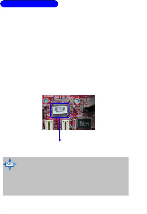
1394 GUID address Label (optional)
MSI Reminds You...
1. Each board will be giv en a unique 1394 G UID from the manufacturer’s default settings in the system BIOS.
2. Use the flash utility or Live Update from MSI’s website for BIOS update. The 1394 GUID address is burnt in the BIOS core. If the 1394 GUID address is lost due to an unpredictable event, such as replacing a new BIOS chip, users can use the utility from MSI’s website by entering the 1394 GUID address to recover its original one.
1-4
Getting Started
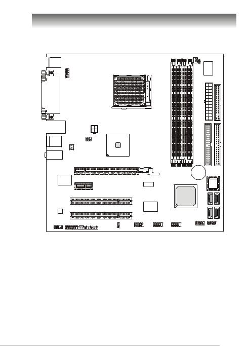
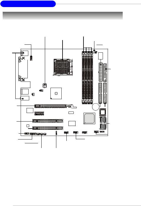
Mainboard Layout
|
|
|
|
|
|
|
|
CPU_FAN |
|
|
Top : mouse |
|
|
|
|
|
|
|
|
|
|
Bottom: keyboard |
|
|
|
|
|
|
|
JCI2 |
|
|
|
|
|
|
|
|
|
|
|
|
|
JCOM2 |
|
|
|
DIMM1 |
DIMM2 |
|
DIMM3 |
DIMM4 |
|
|
|
|
|
|
|
|
|
|
|
||
Top : |
|
|
|
|
|
|
|
|
|
|
Parallel Port |
|
|
|
|
|
|
|
|
|
|
Bottom: |
|
|
|
|
|
|
|
|
|
|
DVI port (for RS482)(optional) |
|
|
|
|
|
|
|
|
||
VGA port (for Rs482) |
|
|
|
|
|
|
|
|
||
|
|
|
|
|
|
|
|
|
ATX 1 |
FD D 1 |
Top: LAN jack |
|
JPW1 |
|
|
|
|
|
|
|
|
|
|
|
|
|
|
|
|
|
|
|
Bottom: USB ports |
|
|
|
|
|
|
|
|
|
|
Top: 1394 port (optional) |
ATI |
|
|
|
|
|
|
|
||
RS482/ RX480 |
|
|
|
|
|
|
|
|||
Bottom: USB ports |
JTV1(for RS482) |
|
|
|
|
|
|
|
|
|
T:Line-In |
SYS_FAN |
|
|
|
|
|
|
|
|
|
M:LineOut |
|
|
|
|
|
|
|
|
|
|
B:Mic-In |
|
|
|
|
|
|
|
|
IDE 2 |
IDE 1 |
|
|
PCIE16X1 |
|
|
|
|
|
|
||
|
|
|
|
|
|
|
|
|
|
|
|
|
|
|
|
|
|
|
BATT |
|
|
LAN |
|
|
|
|
|
|
|
|
+ |
|
|
PCIE1X1 |
|
|
|
|
|
|
|
|
|
Chip |
|
|
|
|
|
|
|
|
|
|
|
|
|
|
|
|
|
|
|
BIOS |
|
|
|
|
|
|
|
|
|
|
|
|
|
|
PCI1 |
|
|
|
|
|
ATI |
SATA4 |
SATA3 |
|
|
|
|
|
|
|
SB450 |
|||
|
|
|
|
|
|
|
|
|||
|
|
|
|
|
|
|
|
|
||
|
|
|
|
|
VIA |
|
|
|
|
|
|
|
PCI 2 |
|
|
VT6307 |
|
|
|
SATA2 |
SATA1 |
ALC880 |
|
|
|
|
|
|
|
|||
|
|
|
|
|
|
|
|
|
||
|
|
|
|
(optional) |
|
|
|
|
|
|
|
|
|
JCMOS |
J1394_1 |
JUSB1 |
|
JUSB2 |
JFP1 |
JLPC1 |
|
JAUD1 |
J1 |
JCD1 SPDOUT SPDIN |
|
|
|
|
||||
|
|
|
|
|
|
|
||||
|
|
|
|
|
|
|
|
|||
RS482M4/ RX480M4 Series (MS-7191 v1.X) |
|
|||||||||
|
|
|
M-ATX Mainboard |
|
|
|
|
|
||
1-5
MS-7191 M-ATX Mainboard
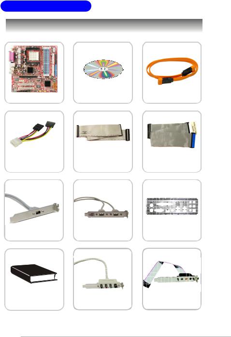
Packing Checklist
MSI motherboard |
MSI Driver/Utility CD |
SATA Cable (Optional) |
|
|
Power Cable |
Standard Cable for |
Standard Cable for |
|
Floppy Disk |
IDE Devices |
||
|
1394 Bracket (Optional) |
USB Bracket (Optional) |
Back IO Shield |
User’s Guide |
TV-out Bracket |
Audio-out Bracket |
|
(Optional) |
(Optional) |
||
|
* The pictures are for reference only. Your packing contents may vary depending on the model you purchased.
1-6

Hardware Setup
Hardware Setup
This chapter tells you how to install the CPU, memory modules, and expansion cards, as well as how to setup the jumpers on the mainboard. Also, it provides the instructions on connecting the peripheral devices, such as the mouse, keyboard, etc.
While doing the installation, be careful in holding the components and follow the installation procedures.
2-1
MS-7191 M-ATX Mainboard
Quick Components Guide
JPW1, p.2-9 |
|
DDR DIMMs, p.2-7 |
|
JTV1, |
CPU, p.2-3 |
CPU_FAN, p.2-15 |
|
p.2-22 |
|
|
|
JCOM2, p.2-20 |
|
JCI2, p.2-18 |
|
Back Panel |
|
|
|
I/O, p.2-10 |
|
|
|
|
|
ATX1, p.2-9 |
|
|
|
FDD1, p.2-15 |
|
SYS_FAN, |
|
|
|
p.2-15 |
|
|
|
PCI Express |
|
IDE1/2, p.2-16 |
|
Slot, p.2-24 |
|
||
PCI Slots, |
|
SATA1~4, |
|
p.2-24 |
|
||
|
|
p.2-17 |
|
JAUD1, p.2-18 |
|
JFP1, p.2-21 |
|
|
|
||
J1, p.2-19 |
|
|
|
JCD1, p.2-18 |
J1394_1, p.2-20 |
||
SPDOUT, p.2-19 |
|
JUSB1, JUSB2, p.2-21 |
|
JCMOS, p.2-23 |
|||
|
|||
SPDIN, p.2-19 |
|
||
2-2

Hardware Setup
Central Processing Unit: CPU
The mainboard supports AMD® Athlon64 processor. The mainboard uses a CPU socket called Socket-939 for easy CPU installation. When you are installing the CPU, make sure the CPU has a heat sink and a cooling fan attached on the top to prevent overheating. If you do not have the heat sink and cooling fan, contact your dealer to purchase and install them before turning on the computer.
For the latest information about CPU, please visit http://www.msi.com.tw/program/products/mainboard/mbd/pro_mbd_cpu_support.php.
MSI Reminds You...
Overheating
Overheating will seriously damage the CPU and system, always make sure the cooling fan can work properly to protect the CPU from overheating.
Replacing the CPU
While replacing the CPU, always turn off the ATX power supply or unplug the power supply’s power cord from grounded outlet first to ensure the safety of CPU.
2-3
MS-7191 M-ATX Mainboard
CPU Installation Procedures for Socket 939
1. Please turn off the power and |
|
|
unplug the power cord before |
|
Open Lever |
installing the CPU. |
|
|
|
Sliding |
90 degree |
|
Plate |
|
|
|
2. Pull the lever sideways away from the socket. Make sure to raise the lever up to a 90-de- gree angle.
Gold arrow
3. Look for the gold arrow of the CPU. The gold arrow should point as shown in the picture. The CPU c an only f it i n the c orrec t orientation.
4.If the CPU is correctly installed, the pins should be completely embedded into the socket and can not be seen. Please note that any violation of the correct installation proc edures may cause permanent damages to your mainboard.
5.Press the CPU down firmly into the socket and close the lever. As the CPU is likely to move while the lever is being closed, always close the lever with your fingers pressing tightly on top of the CPU to make sure the CPU is properly and completely embedded into the socket.
Correct CPU placement
Gold arrow |
O |
|
Gold arrow
2-4
Hardware Setup
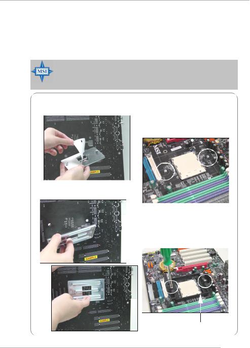
Installing AMD Athlon64 CPU Cooler Set
When you are installing the CPU, make sure the CPU has a heat sink and a cooling fan attached on the top to prevent overheating. If you do not have the heat sink and cooling fan, contact your dealer to purchase and install them before turning on the computer.
MSI Reminds You...
Mainboard photos shown in this section are for demonstration of the cooler installation for Socket 939 CPUs only. The appearance of your mainboard may vary depending on the model you purchase.
1.Detach the shield off the backplate’s paster.
2.Turn over the mainboard, and install the backplate to the proper position.
3.Turn over the mainboard again, and plac e the mainboard on the f lat surface. Locate the two screw holes of the mainboard.
4.Align the retention mechanism and the backplate.
Fix the retention mechanism and the backplate with two screws.
retention mechanism
2-5
MS-7191 M-ATX Mainboard
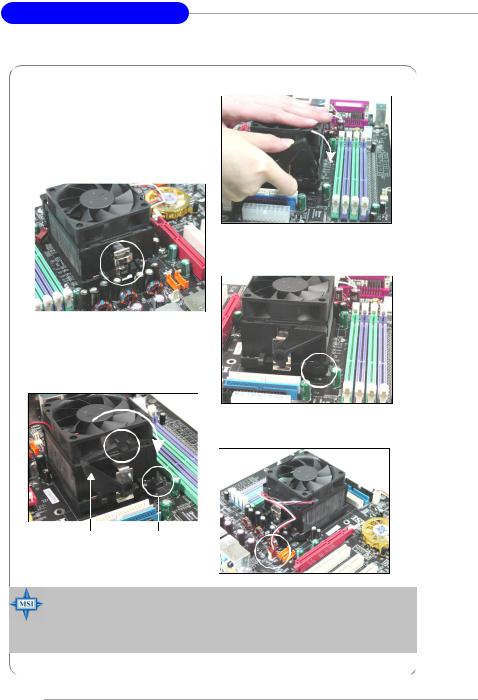
5.Position the cooling set onto the retention mechanism.
Hook one end of the clip to hook first, and then press down the other end of the clip to fasten the cooling set on the top of the retention mechanism.
6.Locate the Fix Lever, Safety Hook and the Fixed Bolt.
Lift up the intensive fixed lever.
Safety Hook
7. Fasten down the lever.
8.Make sure the safety hook completely clasps the fixed bolt of the retention mechanism.
9.Attach the CPU Fan cable to the CPU fan connector on the mainboard.
Fixed Lever |
Fixed Bolt |
MSI Reminds You...
While disconnecting the Safety Hook from the fixed bolt, it is necessary to keep an eye on your fingers, because once the Safety Hook is disconnected from the fixed bolt, the fixed lever will spring back instantly.
2-6
Hardware Setup
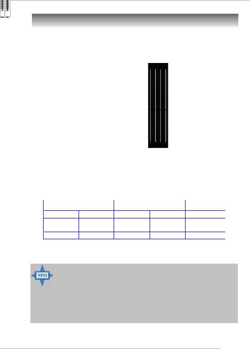
Memory
The mainboard provides 4 slots for 184-pin DDR DIMM (Double In-Line Memory Module) modules and supports the memory size up to 4GB. You can install DDR 333/ 400 modules on the DDR DIMM slots (DIMM 1~4).
DIMM1~DIMM4 (from left to right)
DIMM Module Combination
Install at least one DIMM module on the slots. Each DIMM slot supports up to a maximum size of 1GB. Users can install either singleor double-sided modules to meet their own needs. Users may install memory modules of different type and density on different-channel DDR DIMMs. However, memory modules of the same type and density are required while using dual-channel DDR, or instability may happen.
GREEN Slots |
PURPLE Slots |
|
||
DIMM1 (CH A) |
DIMM3 (CH A) |
DIMM2 (CH B) |
DIMM4 (CH B) |
Mode |
128MB~1GB |
|
128MB~1GB |
|
Dual Channel |
|
128MB~1GB |
|
128MB~1GB |
Dual Channel |
128MB~1GB |
128MB~1GB |
128MB~1GB |
128MB~1GB |
Dual Channel |
MSI Reminds You...
-In dual-channel mode, make sure that you install memory modules of the same type and density on DDR DIMMs.
-To enable successful system boot-up, always insert the memory modules into the DIMM1 slots first.
-This mainboard DO NOT support the memory module installed with more than 18 pieces of IC (integrated circuit).
-Do not support three memory modules.
2-7
MS-7191 M-ATX Mainboard
Recommended Memory Combination List |
|
|||
|
DIMM Slots |
|
|
|
Green |
Purple |
Green |
Purple |
Max Speed |
DIMM1 |
DIMM2 |
DIMM3 |
DIMM4 |
DDR400 |
S |
- |
- |
- |
|
- |
- |
S |
- |
DDR400 |
D |
- |
- |
- |
DDR400 |
- |
- |
D |
- |
DDR400 |
S |
- |
S |
- |
DDR400 |
D |
- |
D |
- |
DDR333 |
S |
S |
- |
- |
DDR400 |
- |
- |
S |
S |
DDR400 |
D |
D |
- |
- |
DDR400 |
- |
- |
D |
D |
DDR400 |
S |
S |
S |
S |
DDR400 |
D |
D |
D |
D |
DDR333 |
|
S: Single Side |
D: Double Side |
||
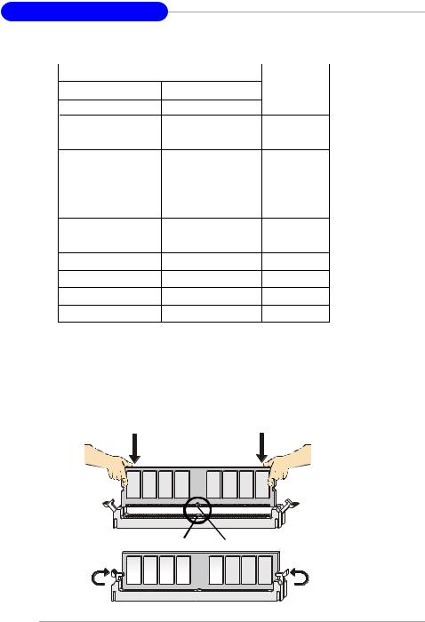
Installing DDR Modules
1.The DDR DIMM has only one notch on the center of module. The module will only fit in the right orientation.
2.Insert the DIMM memory module vertically into the DIMM slot. Then push it in until the golden finger on the memory module is deeply inserted in the socket.
3.The plastic clip at each side of the DIMM slot will automatically close.
Volt Notch
2-8
Hardware Setup
Power Supply
The mainboard supports ATX power supply for the power system. Before inserting the power supply connector, always make sure that all components are installed properly to ensure that no damage will be caused.
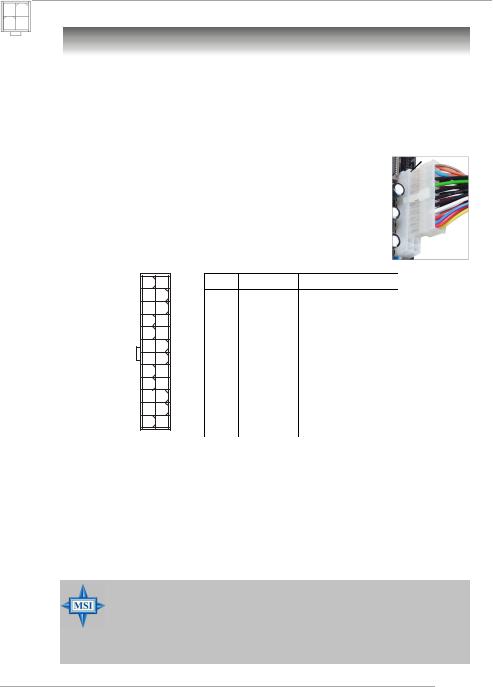
ATX 24-Pin Power Connector: ATX1
This connector allows you to connect an ATX 24-pin power supply. To connect the ATX 24-pin power supply, make sure the plug of the power
supply is inserted in the proper orientation and the pins are aligned. Then push down the power supply firmly into the connector.
You may use the 20-pin ATX power supply as you like. If you’d like to use the 20-pin ATX power supply, please plug your power supply along with pin 1 & pin 13 (refer to the image at the right hand). There is also a foolproof design on pin 11, 12, 23 & 24 to avoid wrong installation.
Pin Definition
13 |
1 |
ATX1 |
|
24 |
12 |
PIN |
SIGNAL |
PIN |
SIGNAL |
1 |
+3.3V |
13 |
+3.3V |
2 |
+3.3V |
14 |
-12V |
3 |
GND |
15 |
GND |
4 |
+5V |
16 |
PS-ON# |
5 |
GND |
17 |
GND |
6 |
+5V |
18 |
GND |
7 |
GND |
19 |
GND |
8 |
PWROK |
20 |
Res |
9 |
5VSB |
21 |
+5V |
10 |
+12V |
22 |
+5V |
11 |
+12V |
23 |
+5V |
12 |
NC |
24 |
GND |
ATX 12V Power Connector: JPW1
This 12V power connector is used to provide power to the CPU.
Pin Definition
|
JPW1 |
|
|
|
|
PIN |
SIGNAL |
||
2 |
1 |
|||
1 |
GND |
|||
4 |
3 |
|||
2 |
GND |
|||
|
|
3 |
12V |
|
|
|
4 |
12V |
MSI Reminds You...
1.These two connectors connect to the ATX power supply and have to work together to ensure stable operation of the mainboard.
2.Power supply of 350 watts (and above) is highly recommended for system stability.
3.ATX 12V power connection should be greater than 18A.
2-9
MS-7191 M-ATX Mainboard
Back Panel
Parallel |
|
L-In |
LAN |
1394 Port |
|
M ouse |
|
(Optional) |
Keyboard |
DVI Port |
VGA Port |
USB |
USB |
L-Out |
|
|
|
(for RS482) |
(for RS482) |
Ports |
Ports |
Mic |
|
|
(optional) |
|
|
|
|
Mouse/Keyboard Connector
The mainboard provides a standard PS/2® mouse/keyboard mini DIN connector for attaching a PS/2® mouse/keyboard. You can plug a PS/2® mouse/keyboard directly into this connector. The connector location and pin assignments are as follows:
|
|
|
Pin Definition |
||
6 |
5 |
PIN |
SIGNAL |
DESCRIPTION |
|
4 |
3 |
1 |
Mouse/Keyboard Data |
Mouse/Keyboard data |
|
|
|
2 |
NC |
Noconnection |
|
2 |
1 |
3 |
GND |
Ground |
|
4 |
VCC |
+5V |
|||
|
|
||||
PS/2 Mouse / Keyboard |
5 |
Mouse/KeyboardClock |
Mouse/Keyboardclock |
||
(6-pin Female) |
6 |
NC |
Noconnection |
||
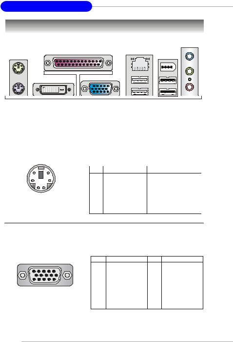
VGA Connector ( for RS482 only)
The mainboard provides a DB 15-pin female connector to connect a VGA monitor.
5 |
1 |
Pin |
Signal Description |
Pin |
Signal Description |
|
1 |
RED |
2 |
GREEN |
|||
|
|
|||||
|
|
3 |
BLUE |
4 |
N/C |
|
|
|
5 |
GND |
6 |
GND |
|
|
|
7 |
GND |
8 |
GND |
|
15 |
11 |
9 |
+5V |
10 |
GND |
|
VGA Connector |
11 |
N/C |
12 |
SDA |
||
13 |
Horizontal Sync |
14 |
Vertical Sync |
|||
(DB 15-pin) |
15 |
SCL |
|
|
||
2-10
Hardware Setup
Digital Panel Connector (for RS482 only) (optional)
The mainboard provides a DVI (Digital Visual Interface) connector which allows you to connect an LCD monitor. The DVI connector provides a high-speed digital interconnection between the computer and its display device. To connect a LCD monitor, simply plug your monitor cable into the DVI connector, and make sure that the other end of the cable is properly connected to your monitor. (refer to your monitor manual for more information.)
|
1 |
8 |
|
|
17 |
24 |
|
|
DVI Connector |
||
Pin |
Signal Assignment |
Pin |
Signal Assignment |
1 |
T.M.D.S.* Data2- |
13 |
T.M.D.S. Data3+ |
2 |
T.M.D.S. Data2+ |
14 |
+5V |
3 |
T.M.D.S. Data2/4 Shield |
15 |
GND (for +5V) |
4 |
T.M.D.S. Data4- |
16 |
Hot Plug Detect |
5 |
T.M.D.S. Data4+ |
17 |
T.M.D.S. Data0- |
6 |
DDC Clock |
18 |
T.M.D.S. Data0+ |
7 |
DDC Data |
19 |
T.M.D.S. Data0/5 Shield |
8 |
N/C |
20 |
T.M.D.S. Data5- |
9 |
T.M.D.S. Data1- |
21 |
T.M.D.S. Data5+ |
10 |
T.M.D.S. Data1+ |
22 |
T.M.D.S. Clock Shield |
11 |
T.M.D.S. Data1/3 Shield |
23 |
T.M.D.S. Clock+ |
12 |
T.M.D.S. Data3- |
24 |
T.M.D.S. Clock- |
MSI Reminds You...
Please note that the DVI connector doesn’t support to connect the D- Sub to DVI converter.
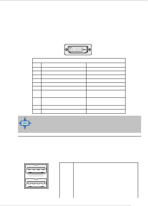
USB Connectors
The mainboard provides an OHCI (Open Host Controller Interface) Universal Serial Bus root for attaching USB devices such as keyboard, mouse or other USBcompatible devices. You can plug the USB device directly into the connector.
1 |
2 |
3 |
4 |
5 |
6 |
7 |
8 |
USB Ports
USB Port Description
PIN |
SIGNAL |
DESCRIPTION |
1 |
VCC |
+5V |
2 |
-Data 0 |
Negative Data Channel 0 |
3 |
+Data0 |
Positive Data Channel 0 |
4 |
GND |
Ground |
5 |
VCC |
+5V |
6 |
-Data 1 |
Negative Data Channel 1 |
7 |
+Data 1 |
Positive Data Channel 1 |
8 |
GND |
Ground |
2-11
MS-7191 M-ATX Mainboard
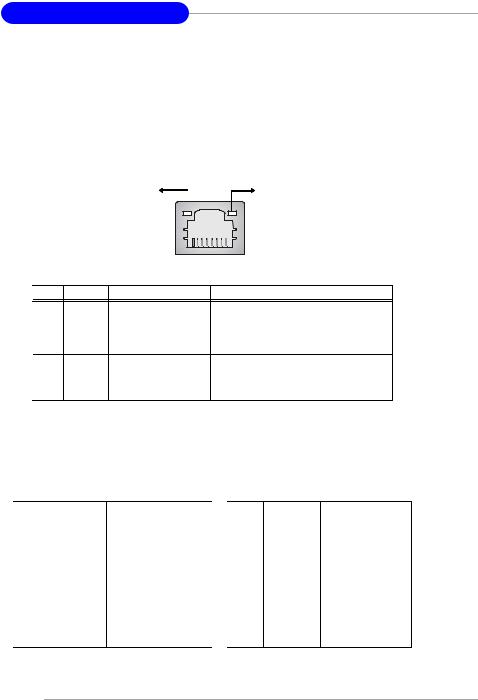
LAN (RJ-45) Jack:10/100 LAN (8100C) or Giga-bit LAN (8110S => optional)
The mainboard provides 1 standard RJ-45 jack for connection to single Local Area Network (LAN). This LAN enables data to be transferred at 10/ 100Mbps or (1000Mbps => for 8110S only). You can connect a network cable to it.
Activity Indicator |
Link Indicator |
|
|
8 |
1 |
|
|
|
|
RJ-45 LAN Jack |
|||
LED |
Color |
LED State |
Condition |
||
|
|
Off |
LAN link is not established. |
||
Left |
Orange |
On (steady state) |
LAN link is established. |
||
|
|
On (brighter & pulsing) |
The computer is communicating with another |
|
|
|
|
|
computer on the LAN. |
||
Right |
Green |
Off |
10 Mbit/sec data rate is selected. |
||
|
On |
100 Mbit/sec data rate is selected. |
|
||
|
Orange |
On |
1000 Mbit/sec data rate is selected. |
|
|
The pin assignments vary depending on the transfer rates: 10/100Mbps or 1000Mbps. Note that Pin 1/2, 3/6, 4/5, 7/8 must work in pairs. Please refer to the following for details:
|
10/100 LAN Pin Definition |
|
Giga-bit LAN Pin Definition |
||
PIN |
SIGNAL |
DESCRIPTION |
PIN |
SIGNAL |
DESCRIPTION |
1 |
TDP |
Transmit Differential Pair |
1 |
D0P |
Differential Pair 0+ |
2 |
TDN |
Transmit Differential Pair |
2 |
D0N |
Differential Pair 0- |
3 |
RDP |
Receive Differential Pair |
3 |
D1P |
Differential Pair 1+ |
4 |
NC |
Not Used |
4 |
D2P |
Differential Pair 2+ |
5 |
NC |
Not Used |
5 |
D2N |
Differential Pair 2- |
6 |
RDN |
Receive Differential Pair |
6 |
D1N |
Differential Pair 1- |
7 |
NC |
Not Used |
7 |
D3P |
Differential Pair 3+ |
8 |
NC |
Not Used |
8 |
D3N |
Differential Pair 3- |
2-12
Hardware Setup
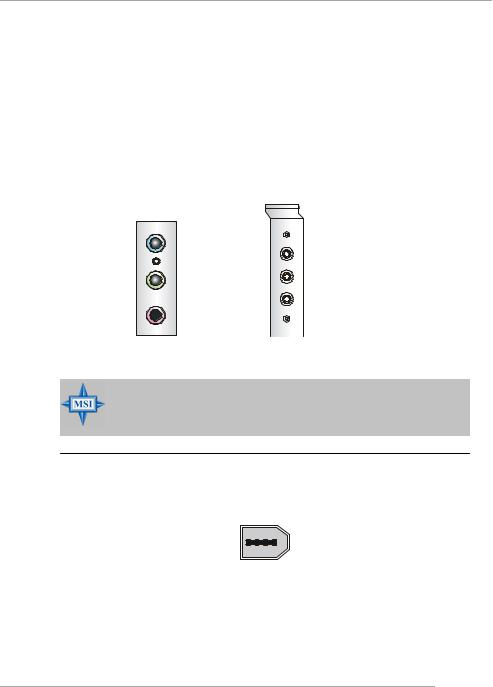
Audio Port Connectors & Audio Header (J1)
The 3 audio jacks are for 2-channel mode for stereo speaker output: Line Out is a connector for Speakers or Headphones. Line In is used for external CD player, Tape player, or other audio devices. Mic is a connector for microphones.
However, there is an advanced audio application provided by Realtek ALC880 to offer support for 7.1-channel audio operation. You can use the external audio cable and the rear audio connectors to function the 2-/4-/5.1-/7.1- channel audio.
Line In
Rear Out
Line Out |
Center and Subwoofer Out |
Side Surround Out
MIC
MSI Reminds You...
For the advanced functions of the audio codec, please refer to Appendix A: Introduction to Realtek ALC880 Audio Codec for details.
IEEE 1394 Port (optional)
There is one 1394 port on the back panel providing the connection for 1394 devices.
1394 port
2-13
 Loading...