

MSI RG54GS2 User Manual

MSI RG54GS2
Wireless 11g Broadband Router Plus
USB Print Server
User Manual

FCC Caution
1. The device complies with Part 15 of the FCC rules. Operation is subject to
the following two conditions:
(1) This device may not cause harmful interference, and
(2) This device must accept any interference received, including interference
that may cause undesired operation.
2. FCC RF Radiation Exposure Statement: The equipment complies with FCC
RF radiation exposure limits set forth for an uncontrolled environment.
This equipment should be installed and operated with a minimum
distance of 20 centimeters between the radiator and your body.
3. This Transmitter must not be co-located or operating in conjunction with
any other antenna or transmitter.
4. Changes or modifications to this unit not expressly approved by the
party responsible for compliance could void the user authority to operate
the equipment.
Copyright Notice
The material in this document is the intellectual property of MICRO-STAR INTERNATIONAL.
We take every care in the preparation of this document, but no guarantee is given as to the
correctness of its contents. Our products are under continual improvement and we reserve the
right to make changes without notice.
Trademarks
Microsoft Windows and Internet Explorer are registered trademarks or trademarks of Microsoft
Corporation.
All brand names, icons, and trademarks used in this manual are the sole property of their
respective owners.
Revision History
Revision History Date
V 1.0 First Release May 2005

Important Safety Precautions
Always read and follow these basic safety precautions carefully when handling any
piece of electronic component.
1. Keep this User Manual for future reference.
2. Keep this equipment away from humidity.
3. Lay this equipment on a reliable flat surface before setting it up.
4. The openings on the enclosure are for air convection hence protects the
equipment from overheating.
5. All cautions and warnings on the equipment should be noted.
6. Never pour any liquid into the opening that could damage or cause electrical
shock.
7. If any of the following situations arises, get the equipment checked by a
service personnel:
•Liquid has penetrated into the equipment
•The equipment has been exposed to moisture
•The equipment has not work well or you can not get it work according to
User Manual
•The equipment has dropped and damaged
•If the equipment has obvious sign of breakage
8. DO NOT LEAVE THIS EQUIPMENT IN AN ENVIRONMENT
UNCONDITIONED, STORAGE TEMPERATURE ABOVE 60°C OR
BELOW -20°C, IT MAY DAMAGE THE EQUIPMENT.

Contents
Chapter 1 Introduction..........................................................................................................1
Functions and Features.....................................................................................................1
Packing List.....................................................................................................................3
Chapter 2 Hardware Installation............................................................................................4
2.1 Panel Layout..............................................................................................................4
2.2 Procedure for Hardware Installation...........................................................................6
Chapter 3 Network Settings and Software Installation...........................................................7
3.1 Make Correct Network Settings of Your Computer.....................................................7
Chapter 4 Configuring Wireless Broadband Router...............................................................8
4.1 Start-up and Log in.....................................................................................................9
4.2 Wizard........................................................................................................................9
4.3 Setup........................................................................................................................10
4.4 Advanced.................................................................................................................21
4.5 Administration..........................................................................................................41
4.6 Status.......................................................................................................................46
Chapter 5 Print Server.........................................................................................................50
5.1 Configuring on Windows 95/98 Platforms................................................................50
5.2 Configuring on Windows NT Platforms....................................................................52
5.3 Configuring on Windows 2000 and XP Platforms.....................................................53
5.4 Configuring on Unix-like based Platforms................................................................57
5.5 Configuring on Apple PC.........................................................................................62
Appendix A TCP/IP Configuration for Windows 95/98......................................................63
Appendix B 802.1x Setting.................................................................................................68
Appendix C WPA-PSK and WPA.......................................................................................74
Appendix D FAQ and Troubleshooting...............................................................................87
Reset to factory Default..................................................................................................87
Appendix E Product Specification.......................................................................................88

1
C
h
a
p
t
e
r
1
I
n
t
r
o
d
u
c
t
i
o
n
C
h
a
p
t
e
r
1
I
n
t
r
o
d
u
C
h
a
p
t
e
r
1
I
n
t
r
Congratulations on your purchase of this outstanding Wireless Broadband Router. This product is specifically
designed for Small Office and Home Office needs. It provides a complete SOHO solution for Internet surfing, and is
easy to configure and operate even for non-technical users. Instructions for installing and configuring this product
can be found in this manual. Before you install and use this product, please read this manual carefully for fully
exploiting the functions of this product.
Functions and Features
Router Basic functions
l Auto-sensing Ethernet Switch
Equipped with a 4-port auto-sensing Ethernet switch.
l WAN type supported
The router supports some WAN types, Static, Dynamic, PPPoE , PPTP ,L2TP, Dynamic IP with Road
Runner.
o
d
u
c
c
t
i
o
n
t
i
o
n
l Firewall
All unwanted packets from outside intruders are blocked to protect your Intranet.
l DHCP server supported
All of the networked computers can retrieve TCP/IP settings automatically from this product.
l Web-based configuring
Configurable through any networked computer’s web browser using Netscape or Internet Explorer.
l Virtual Server supported
Enable you to expose WWW, FTP and other services on your LAN to be accessible to Internet users.
l User-Definable Application Sensing Tunnel
User can define the attributes to support the special applications requiring multiple connections, like
Internet gaming, video conferencing, Internet telephony and so on, then this product can sense the
application type and open multi-port tunnel for it.
l DMZ Host supported
Lets a networked computer be fully exposed to the Internet; this function is used when special application
sensing tunnel feature is insufficient to allow an application to function correctly.
l Statistics of WAN Supported
Enables you to monitor inbound and outbound packets

2
Wireless functions
l High speed for wireless LAN connection
Up to 54Mbps data rate by incorporating Orthogonal Frequency Division Multiplexing (OFDM).
l Roaming
Provides seamless roaming within the IEEE 802.11b (11M) and IEEE 802.11g (54M) WLAN
infrastructure.
l IEEE 802.11b compatible (11M)
Allowing inter-operation among multiple vendors.
l IEEE 802.11g compatible (54M)
Allowing inter-operation among multiple vendors.
l Auto fallback
54M, 48M, 36M, 24M, 18M, 12M, 6M data rate with auto fallback in 802.11g mode.
11M, 5.5M, 2M, 1M data rate with auto fallback in 802.11b mode.
Security functions
l Packet filter supported
Packet Filter allows you to control access to a network by analyzing the incoming and outgoing packets
and letting them pass or halting them based on the IP address of the source and destination.
l Domain Filter Supported
Let you prevent users under this device from accessing specific URLs.
l URL Blocking Supported
URL Blocking can block hundreds of websites connection by simply a keyword.
l VPN Pass-through
The router also supports VPN pass-through.
l 802.1X supported
When the 802.1X function is enabled, the Wireless user must authenticate to this router first to use the
Network service.
l Support WPA-PSK and WPA
When the WPA function is enabled, the Wireless user must authenticate to this router first to
use the Network service
l SPI Mode Supported
When SPI Mode is enabled, the router will check every incoming packet to detect if this packet is valid.
l DoS Attack Detection Supported
When this feature is enabled, the router will detect and log the DoS attack comes from the Internet.

3
Advanced functions
l System time Supported
Allow you to synchronize system time with network time server.
l E-mail Alert Supported
The router can send its info by mail.
l Dynamic dns Supported
At present,the router has 3 ddns.dyndns,TZO.com and dhs.org.
l SNMP Supported
The router supports basic SNMP function.
l Routing Table Supported
Now, the router supports static routing.
l Schedule Rule supported
Customers can control some functions, like virtual server and packet filters when to access or when to
block.
Other functions
l UPNP (Universal Plug and Play)Supported
The router also supports this function. The applications: X-box, Msn Messenger.
Packing List
l Wireless broadband router unit
l Installation CD-ROM
l Power adapter
l CAT-5 UTP Fast Ethernet cable

4
C
h
a
p
t
e
r
2
C
h
a
p
h
a
p
t
t
C
2.1 Panel Layout
2.1.1. Front Panel
e
r
2
e
r
2
H
a
r
d
w
a
r
e
I
n
s
t
a
l
l
a
t
i
o
n
H
a
r
d
w
a
r
e
I
n
s
t
a
l
l
H
a
r
d
w
a
r
e
I
n
s
a
t
a
l
l
a
t
i
o
n
t
i
o
n
Figure 2-1 Front Panel
LED Function Color Status Description
POWER
Power
indication
System
Status
status
USB port
USB
activity
WAN port
WAN
activity
Wireless
WLAN
activity
Link/Act.
Link status Green
1~4
Green On Power is being applied to this product.
Green Blinking M1 is flashed once per second to indicate system is alive.
Green On The USB port is linked.
On The WAN port is linked.
Green
Blinking The WAN port is sending or receiving data.
Green Blinking Sending or receiving data via wireless
An active station is connected to the corresponding LAN
On
port.
Blinking The corresponding LAN port is sending or receiving data.
RESET
Reset
Settings
To reset system settings to factory defaults

5
2.1.2. Rear Panel
the port where you will connect your cable (or DSL) modem or
the ports where you will connect networked computers and other
Antenna
LAN Ports 1~4
PWR
Port Description
PWR
WAN
Port 1-4
Power inlet
Ethernet router.
devices.
WAN Port
USB
Figure 2-2 Rear Panel
USB
Connect the USB printer.

6
2.2 Procedure for Hardware Installation
2. Decide where to place your Wireless Broadband Router
You can place your Wireless Broadband Router on a desk or other flat surface, or you can mount it on a wall.
For optimal performance, place your Wireless Broadband Router in the center of your office (or your home) in a
location that is away from any potential source of interference, such as a metal wall or microwave oven. This
location must be close to power and network connection.
2. Setup LAN connection
a. Wired LAN connection: connects an Ethernet cable from your computer’s Ethernet port to one of the LAN
ports of this product.
b. Wireless LAN connection: locate this product at a proper position to gain the best transmit performance
Figure 2-3 Setup of LAN and WAN connections for this product.
3. Setup WAN connection
Prepare an Ethernet cable for connecting this product to your cable/xDSL modem or Ethernet backbone. Figure
2-3 illustrates the WAN connection.
4. Power on
Connecting the power cord to power inlet and turning the power switch on, this product will automatically enter
the self-test phase. When it is in the self-test phase, the indicators M1 will be lighted ON for about 10 seconds,
and then M1 will be flashed 3 times to indicate that the self-test operation has finished. Finally, the M1 will be
continuously flashed once per second to indicate that this product is in normal operation.

7
C
h
a
p
t
e
r
3
N
e
t
w
o
r
k
S
e
t
t
i
n
g
s
a
n
d
S
o
f
t
w
a
r
e
I
n
s
t
a
l
l
a
t
i
o
n
C
h
a
p
t
e
r
3
N
e
t
w
o
r
k
S
e
t
t
i
n
g
s
a
n
d
S
o
f
t
w
a
r
e
I
n
s
t
a
l
l
C
h
a
p
t
e
r
3
N
e
t
w
o
r
k
S
e
t
t
i
n
g
s
a
n
d
S
o
f
t
w
a
r
e
I
n
s
To use this product correctly, you have to properly configure the network settings of your computers and install the
attached setup program into your MS Windows platform (Windows 95/98/NT/2000).
3.1 Make Correct Network Settings of Your Computer
The default IP address of this product is 192.168.1.254, and the default subnet mask is 255.255.255.0. These
addresses can be changed on your need, but the default values are used in this manual. If the TCP/IP environment of
your computer has not yet been configured, you can refer to Appendix A to configure it. For example,
1. configure IP as 192.168.1.1, subnet mask as 255.255.255.0 and gateway as 192.168.1.254, or more easier,
2. configure your computers to load TCP/IP setting automatically, that is, via DHCP server of this product.
After installing the TCP/IP communication protocol, you can use the ping command to check if your computer has
successfully connected to this product. The following example shows the ping procedure for Windows 95 platforms.
First, execute the ping command
a
t
a
l
l
a
t
i
o
n
t
i
o
n
ping 192.168.1.254
If the following messages appear:
Pinging 192.168.1.254 with 32 bytes of data:
Reply from 192.168.1.254: bytes=32 time=2ms TTL=64
a communication link between your computer and this product has been successfully established. Otherwise, if you
get the following messages,
Pinging 192.168.1.254 with 32 bytes of data:
Request timed out.
There must be something wrong in your installation procedure. You have to check the following items in sequence:
1. Is the Ethernet cable correctly connected between this product and your computer?
Tip: The LAN LED of this product and the link LED of network card on your computer must be lighted.
2. Is the TCP/IP environment of your computers properly configured?
Tip: If the IP address of this product is 192.168.1.254, the IP address of your computer must be 192.168.1.X
and default gateway must be 192.168.1.254.

8
C
h
a
p
t
e
r
4
C
o
n
f
i
g
u
r
i
n
g
W
i
r
e
l
e
s
s
B
r
o
a
d
b
a
n
d
R
o
u
t
e
r
C
h
a
p
t
e
r
4
C
o
n
f
i
g
u
r
i
n
g
W
i
r
e
l
e
s
s
B
r
o
a
d
b
a
n
d
R
o
C
h
a
p
t
e
r
4
C
o
n
f
i
g
u
r
i
n
g
W
i
r
e
l
e
s
s
B
r
o
a
d
b
a
n
d
This product provides Web based configuration scheme, that is, configuring by your Web browser, such as Netscape
Communicator or Internet Explorer. This approach can be adopted in any MS Windows, Macintosh or UNIX based
platforms.
R
o
u
u
t
e
r
t
e
r
9
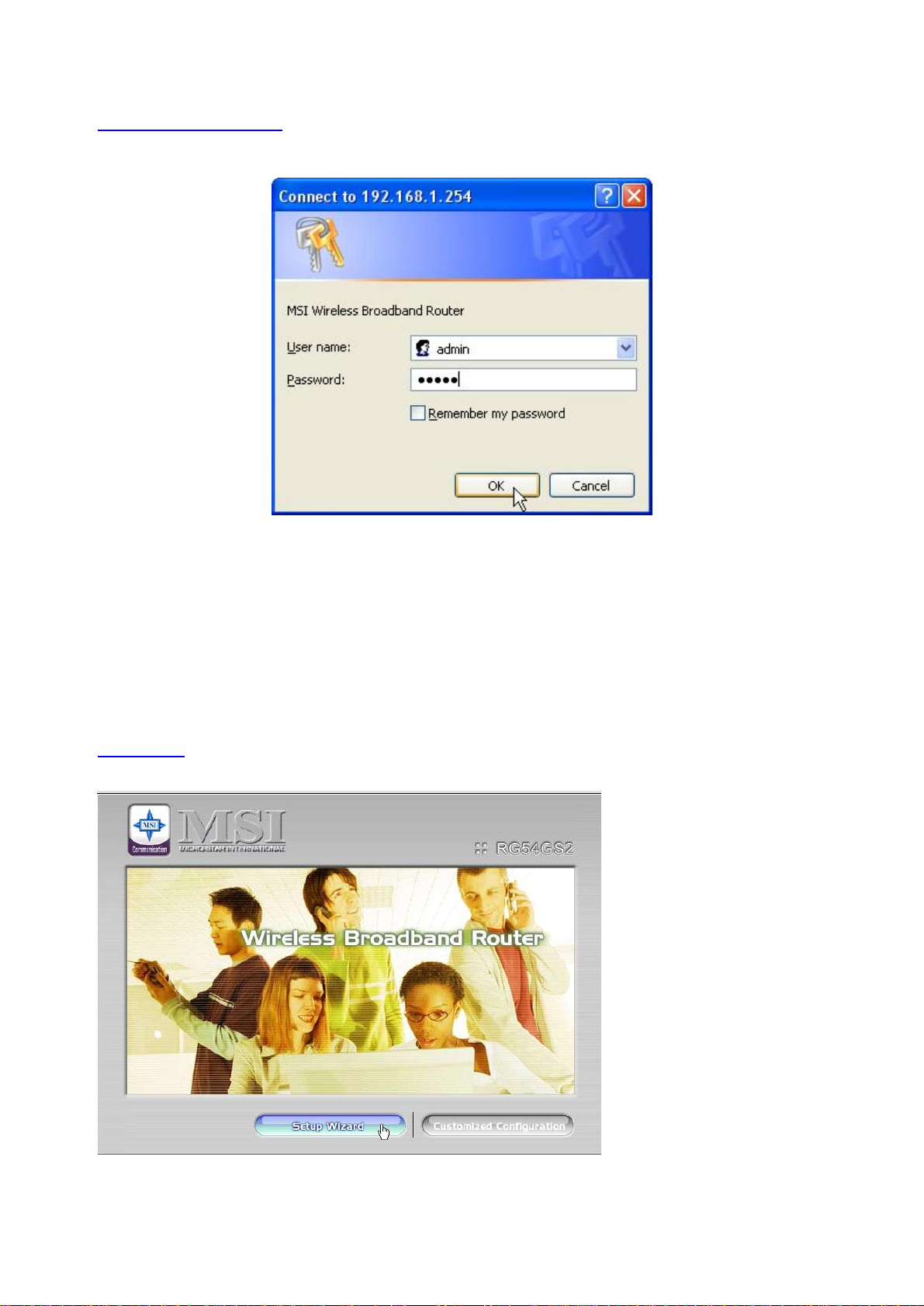
4.1 Start-up and Log in
Activate your browser, and disable the proxy or add the IP address of this product into the exceptions. Then,
type this product’s IP address in the Location (for Netscape) or Address (for IE) field and press ENTER. For
example: http://192.168.1.254.
After the connection is established, you will see the web user interface of this product. To log in as an administrator,
enter the system password (the factory setting is ”admin”) in the Password field and click on the OK button. If
the password is correct, the web appearance will be changed into administrator configure mode. As listed in its main
menu, there are several options for system administration.
4.2 Wizard
Setup Wizard will guide you through a basic configuration procedure step by step.Press ”Next >”

10
Setup Wizard - Select WAN Type: For detail settings, please refer to 4.3.1 IP Setting.
4.3 Setup

11
4.3.1 IP Setting – WAN Type, IP Mode
Press “Change”
This option is primary to enable this product to work properly. The setting items and the web appearance depend on

12
the WAN type. Choose correct WAN type before you start.
1. LAN IP Address: the local IP address of this device. The computers on your network must use the LAN IP
address of your product as their Default Gateway. You can change it if necessary.
2. WAN Type: WAN connection type of your ISP. You can click Change button to choose a correct one from the
following four options:
A. Static IP Address: ISP assigns you a static IP address.
B. Dynamic IP Address: Obtain an IP address from ISP automatically.
C. Dynamic IP Address with Road Runner Session Management.(e.g. Telstra BigPond)
D. PPP over Ethernet: Some ISPs require the use of PPPoE to connect to their services.
E. PPTP: Some ISPs require the use of PPTP to connect to their services.
F. L2TP: Some ISPs require the use of L2TP to connect to their services
4.3.1.1 Static IP Address
WAN IP Address, Subnet Mask, Gateway, Primary and Secondary DNS: enter the proper setting provided by your
ISP.
4.3.1.2 Dynamic IP Address
1. Host Name: optional. Required by some ISPs, for example, @Home.
2. Renew IP Forever: this feature enables this product to renew your IP address automatically when the lease time
is expiring-- even when the system is idle.
4.3.1.3 Dynamic IP Address with Road Runner Session Management.(e.g. Telstra BigPond)
1. LAN IP Address is the IP address of this product. It must be the default gateway of your
computers.
2. WAN Type is Dynamic IP Address. If the WAN type is not correct, change it!
3. Host Name: optional. Required by some ISPs, e.g. @Home.
4. Renew IP Forever: this feature enable this product renew IP address automatically when the lease time is
being expired even the system is in idle state.
4.3.1.4 PPP over Ethernet
1. PPPoE Account and Password: the account and password your ISP assigned to you. For security,
this field appears blank. If you don't want to change the password, leave it empty.
2. PPPoE Service Name: optional. Input the service name if your ISP requires it. Otherwise, leave
it blank.
3. Maximum Idle Time: the amount of time of inactivity before disconnecting your PPPoE session.

13
Set it to zero or enable Auto-reconnect to disable this feature.
4. Maximum Transmission Unit (MTU): Most ISP offers MTU value to users. The most common MTU value is
1492.
5. Connection Control:There are 3 modes to select:
Connect-on-demand:The device will link up with ISP when the clients send outgoing packets.
Auto-Reconnect(Always-on):The device will link upw with ISP until the connection is established.
Manually:The device will not make the link until someone clicks the connect-button in the Staus-page.
4.3.1.5 PPTP
1. My IP Address and My Subnet Mask: the private IP address and subnet mask your ISP assigned
to you.
2. Server IP Address: the IP address of the PPTP server.
3. PPTP Account and Password: the account and password your ISP assigned to you. If you don't
want to change the password, keep it empty.
3. Connection ID: optional. Input the connection ID if your ISP requires it.
4. Maximum Idle Time: the time of no activity to disconnect your PPTP session. Set it to zero or
enable Auto-reconnect to disable this feature. If Auto-reconnect is enabled, this product will
connect to ISP automatically, after system is restarted or connection is dropped.
5. Connection Control:There are 3 modes to select:
Connect-on-demand:The device will link up with ISP when the clients send outgoing packets.
Auto-Reconnect(Always-on):The device will link upw with ISP until the connection is established.
Manually:The device will not make the link until someone clicks the connect-button in the Staus-page.

14
4.3.1.6 L2TP
First,Please check your ISP assigned and Select Static IP Address or Dynamic IP Address.
For example:Use Static
1. My IP Address and My Subnet Mask: the private IP address and subnet mask your ISP assigned
to you.
2. Server IP Address: the IP address of the PPTP server.
3. PPTP Account and Password: the account and password your ISP assigned to you. If you don't
want to change the password, keep it empty.
3. Connection ID: optional. Input the connection ID if your ISP requires it.
4. Maximum Idle Time: the time of no activity to disconnect your PPTP session. Set it to zero or
enable Auto-reconnect to disable this feature. If Auto-reconnect is enabled, this product will
connect to ISP automatically, after system is restarted or connection is dropped.

15
6. Connection Control:There are 3 modes to select:
Connect-on-demand:The device will link up with ISP when the clients send outgoing packets.
Auto-Reconnect(Always-on):The device will link upw with ISP until the connection is established.
Manually:The device will not make the link until someone clicks the connect-button in the Staus-page.
4.3.2 Wireless Setting, and 802.1X setting

16
Wireless settings allow you to set the wireless configuration items.
1. Network ID (SSID): Network ID is used for identifying the Wireless LAN (WLAN). Client stations can roam
freely over this product and other Access Points that have the same Network ID. (The factory setting is
“default”)
2. Channel: The radio channel number. The permissible channels depend on the Regulatory Domain.
The factory setting is as follow: channel 6 for North America; channel 7 for European (ETSI); channel 7 for
Japan.
3. WEP Security: Select the data privacy algorithm you want. Enabling the security can protect your data while it
is transferred from one station to another. The standardized IEEE 802.11 WEP (128 or 64-bit) is used here.
4. WEP Key 1, 2, 3 & 4: When you enable the 128 or 64 bit WEP key security, please select one WEP key to be
used and input 26 or 10 hexadecimal (0, 1, 2…8, 9, A, B…F) digits.
5. Pass-phrase Generator: Since hexadecimal characters are not easily
remembered, this device offers a conversion utility to convert a simple
word or phrase into hex.
6. 802.1X Setting
802.1X
Check Box was used to switch the function of the 802.1X. When the 802.1X function is enabled, the Wireless user
must authenticate to this router first to use the Network service.
RADIUS Server
IP address or the 802.1X server’s domain-name.
RADIUS Shared Key
Key value shared by the RADIUS server and this router. This key value is consistent with the key value in the
RADIUS server.

17
WPA-PSK
1. Select Preshare Key Mode
If you select HEX,you have to fill in 64 hexadecimal (0, 1, 2…8, 9, A, B…F) digits
If ASCII,the length of preshare key is from 8 to 63.
2. Fill in the key, Ex 145678
WPA
Check Box was used to switch the function of the WPA. When the WPA function is enabled, the Wireless user must
authenticate to this router first to use the Network service. RADIUS Server
IP address or the 802.1X server’s domain-name.
RADIUS Shared Key
Key value shared by the RADIUS server and this router. This key value is consistent with the key value in the
RADIUS server.

18
4.3.3 WDS
The Wireless Distribution System (WDS) supports peer-to-peer AP communication. Select
Enable to allow Bridge (WDS) mode between routers or Disable to block communication
between routers.
To enable WDS, set the Wireless Bridging (WDS) function to Enable. Enter the Wireless MAC
address of the router to communicate with in the form of two characters separated by a colon and
click Save.
4.3.4 Dynamic DNS
To host your server on a changing IP address, you have to use dynamic domain name service (DDNS).
So that anyone wishing to reach your host only needs to know the name of it. Dynamic DNS will map the name of
your host to your current IP address, which changes each time you connect your Internet service provider.
Before you enable Dynamic DNS, you need to register an account on one of these Dynamic DNS servers that we list
in provider field.
To enable Dynamic DNS click the check box next to Enable in the DDNS field.
Next you can enter the appropriate information about your Dynamic DNS Server.

19
You have to define:
Provider
Host Name
Username/E-mail
Password/Key
You will get this information when you register an account on a Dynamic DNS server.
4.3.5 DHCP Server
Press “More>>”
The settings of a TCP/IP environment include host IP, Subnet Mask, Gateway, and DNS configurations. It is not easy
to manually configure all the computers and devices in your network. Fortunately, DHCP Server provides a rather
simple approach to handle all these settings. This product supports the function of DHCP server. If you enable this
product’s DHCP server and configure your computers as “automatic IP allocation” mode, then when your computer
is powered on, it will automatically load the proper TCP/IP settings from this product. The settings of DHCP server
include the following items:

20
1. DHCP Server: Choose “Disable” or “Enable.”
2. Lease Time: Define the period of time for the IP address leased.
3. IP pool starting Address/ IP pool starting Address: Whenever there is a request, the DHCP
server will automatically allocate an unused IP address from the IP address pool to the requesting computer.
You must specify the starting and ending address of the IP address pool.
4. Domain Name: Optional, this information will be passed to the client.
5. Primary DNS/Secondary DNS: This feature allows you to assign DNS Servers
6. Primary WINS/Secondary WINS: This feature allows you to assign WINS Servers
7. Gateway: The Gateway Address would be the IP address of an alternate Gateway.
This function enables you to assign another gateway to your PC, when DHCP server
offers an IP to your PC.
4.3.6 Print Server
This item shows the print is ready or not.

21
4.4 Advanced
4.4.1 Basic Setting
22
Discard PING from WAN side
When this feature is enabled, any host on the WAN cannot ping this product.
SPI Mode
When this feature is enabled, the router will record the packet information pass through the router like IP address,
port address, ACK, SEQ number and so on. And the router will check every incoming packet to detect if this packet
is valid.
DoS Attack Detection
When this feature is enabled, the router will detect and log the DoS attack comes from the Internet. Currently, the
router can detect the following DoS attack: SYN Attack, WinNuke, Port Scan, Ping of Death, Land Attack etc.
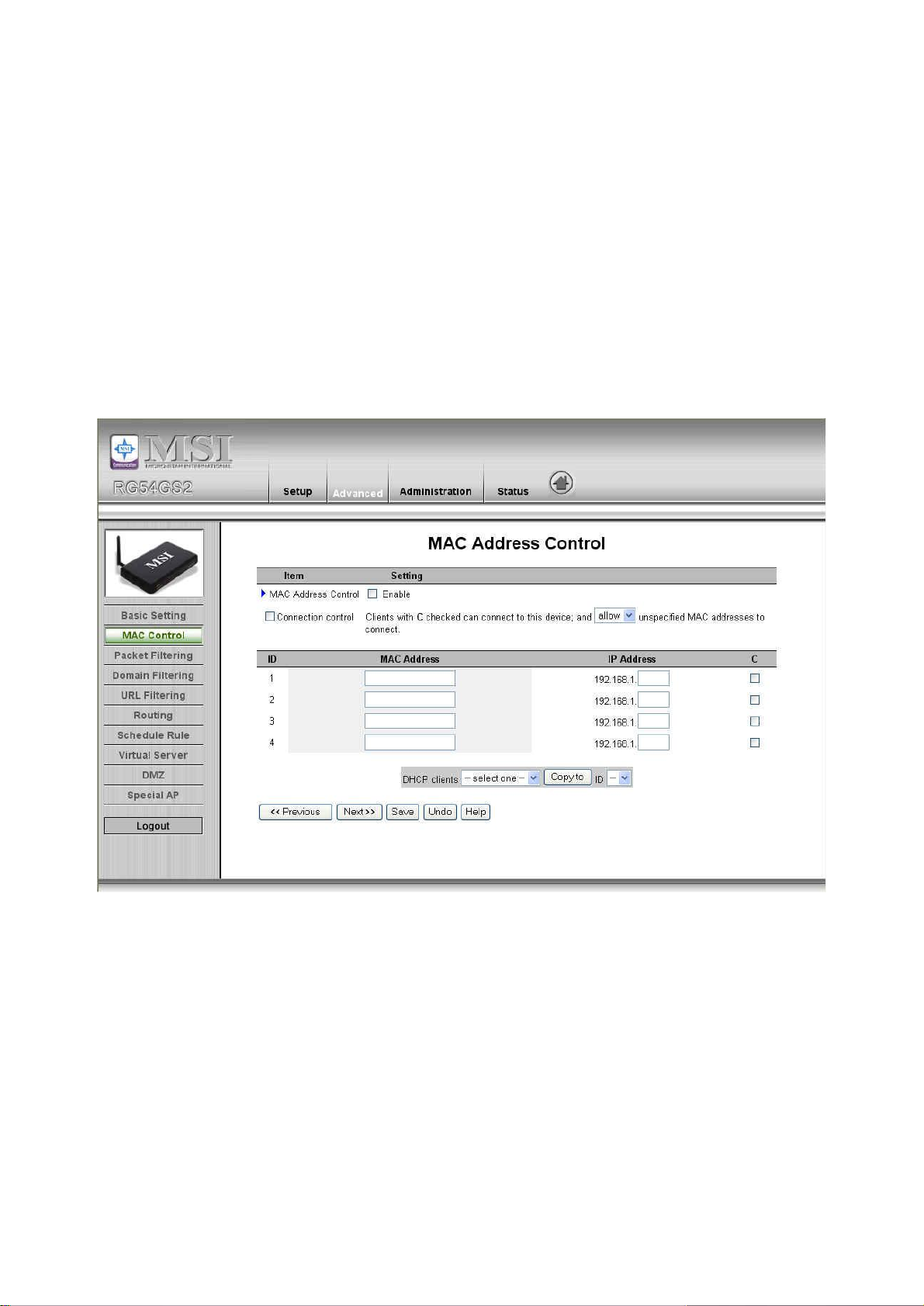
4.4.2 MAC Address Control
MAC Address Control allows you to assign different access right for different users and to assign a specific IP
address to a certain MAC address.
MAC Address Control Check “Enable” to enable the “MAC Address Control”. All of the settings in this page
will take effect only when “Enable” is checked.
Connection control Check "Connection control" to enable the controlling of which wired and wireless
clients can connect to this device. If a client is denied to connect to this device, it
means the client can't access to the Internet either. Choose "allow" or "deny" to allow
or deny the clients, whose MAC addresses are not in the "Control table" (please see
below), to connect to this device.
Association control Check "Association control" to enable the

23
Control table
controlling of which wireless client can
associate to the wireless LAN. If a client is
denied to associate to the wireless LAN, it
means the client can't send or receive any data
via this device. Choose "allow" or "deny" to
allow or deny the clients, whose MAC
addresses are not in the "Control table", to
associate to the wireless LAN.
"Control table" is the table at the bottom of the "MAC Address Control" page. Each
row of this table indicates the MAC address and the expected IP address mapping of a
client. There are four columns in this table:
MAC Address
IP Address
C
A
MAC address indicates a specific client.
Expected IP address of the corresponding
client. Keep it empty if you don't care its IP
address.
When "Connection control" is checked,
check "C" will allow the corresponding client
to connect to this device.
When "Association control" is checked,
check "A" will allow the corresponding client
to associate to the wireless LAN.
In this page, we provide the following Combobox and button to help you to input the MAC address.
You can select a specific client in the “DHCP clients” Combobox, and then click on the “Copy to” button to copy the

24
MAC address of the client you select to the ID selected in the “ID” Combobox.
Previous page and Next Page To make this setup page simple and clear, we have divided the “Control table”
into several pages. You can use these buttons to navigate to different pages.
4.4.3 Packet Filtering
Packet Filter enables you to control what packets are allowed to pass the router. Outbound filter applies on all
outbound packets. However, Inbound filter applies on packets that destined to Virtual Servers or DMZ host only. You
can select one of the two filtering policies:
1. Allow all to pass except those match the specified rules
2. Deny all to pass except those match the specified rules
You can specify 8 rules for each direction: inbound or outbound. For each rule, you can define the following:
• Source IP address
• Source port address
• Destination IP address
• Destination port address
• Protocol: TCP or UDP or both.
• Use Rule#
 Loading...