

Page 1

MSI RG54G2 (MS-6848)
Wireless 11g Broadband Router
User’s Guide
Page 2

FCC Caution
1. The device complies with Part 15 of the FCC rules. Operation is subject to
the following two conditions:
(1) This device may not cause harmful interference, and
(2) This device must accept any interference received, including interference
that may cause undesired operation.
2. FCC RF Radiation Exposure Statement: The equipment complies with FCC
RF radiation exposure limits set forth for an uncontrolled environment.
This equipment should be installed and operated with a minimum
distance of 20 centimeters between the radiator and your body.
3. This Transmitter must not be co-located or operating in conjunction with
any other antenna or transmitter.
4. Changes or modifications to this unit not expressly approved by the
party responsible for compliance could void the user authority to operate
the equipment.
Copyright Notice
The material in this document is the intellectual property of MICRO-STAR INTERNATIONAL. We take every care in the preparation of this document, but no guarantee is
given as to the correctness of its contents. Our products are under continual improvement and we reserve the right to make changes without notice.
Trademarks
Microsoft Windows and Internet Explorer are registered trademarks or trademarks of
Microsoft Corporation.
All brand names, icons, and trademarks used in this manual are the sole property of their
respective owners.
Revision History
Revision History Date
V 1.0 First Release May 2004
Page 3

Important Safety Precautions
Always read and follow these basic safety precautions carefully when handling any
piece of electronic component.
1. Keep this User’s Guide for future reference.
2. Keep this equipment away from humidity.
3. Lay this equipment on a reliable flat surface before setting it up.
4. The openings on the enclosure are for air convection hence protects the
equipment from overheating.
5. All cautions and warnings on the equipment should be noted.
6. Never pour any liquid into the opening that could damage or cause electrical
shock.
7. If any of the following situations arises, get the equipment checked by a
service personnel:
Liquid has penetrated into the equipment
The equipment has been exposed to moisture
The equipment has not work well or you can not get it work
according to User’s Manual
The equipment has dropped and damaged
If the equipment has obvious sign of breakage
8. DO NOT LEAVE THIS EQUIPMENT IN AN ENVIRONMENT
UNCONDITIONED, STORAGE TEMPERATURE ABOVE 60O C OR
BELOW -20OC, IT MAY DAMAGE THE EQUIPMENT.
Page 4

How to Use This Guide
This User’s Guide provides instructions and illustrations on how to install and use your
MSI RG54G2 - the Wireless 11g Broadband Router.
Chapter 1, Introduction, provides general information on the Router.
Chapter 2, Knowing Your Router, introduces physical features of the
Router.
Chapter 3, Connecting Your Router, tells you how to install the Router
into your system.
Chapter 4, Configuring Your PC, instructs how to configure each of your
computers to communicate with this Router.
Chapter 5, Configuring Your Router - Basic, explains how to use the Web
Configuration Utility to manage basic settings of this Router.
Chapter 6, Configuring Your Router - Advanced, details how to intelli-
gently manage advanced features of this Router.
Please note that the setting diagrams or values in this guide are FOR YOUR REFER-
ENCE ONLY. The actual settings and values depend on your system and network. If
you are not sure about these information, please ask your network administrator or MIS
staff for help.
Technical Support
Visit the MSI website for FAQ, technical guide, driver and software updates,
and other information: http://www.msi.com.tw/.
Contact our technical staff at: support@msi.com.tw.
Page 5

Table of Contents
1. Introduction ......................................................................................................... 1
1.1 MSI RG54G2 - Wireless 11g Broadband Router ........................................... 1
1.2 Networking Options ....................................................................................... 3
1.3 Features and Benefits ..................................................................................... 5
1.4 Package Contents ............................................................................................ 6
1.5 System Requirements ..................................................................................... 6
1.6 Specifications .................................................................................................. 7
2. Knowing Your Router ......................................................................................... 11
2.1 Product View .................................................................................................. 11
2.2 Connections Ports .......................................................................................... 12
2.3 LEDs ............................................................................................................... 13
3. Connecting Your Router .................................................................................... 14
4. Configuring Your PC .......................................................................................... 16
4.1 Configuring Windows 98SE/ME .................................................................... 16
4.2 Configuring Windows 2000/XP ...................................................................... 18
5. Configuring Your Router - Basic ...................................................................... 20
5.1 Web Configuration Utility .............................................................................. 20
5.2 Typical Configuration ..................................................................................... 22
6. Configuring Your Router - Advanced ............................................................... 28
6.1 System Settings .............................................................................................. 29
6.2 Internet Settings .............................................................................................. 37
6.3 LAN Settings .................................................................................................. 41
6.4 Wireless Settings ............................................................................................. 46
6.5 NAT Settings .................................................................................................. 59
6.6 Firewall Settings ............................................................................................. 63
Page 6

1
Introduction
>>> 1.1 MSI RG54G2 - Wireless 11g
Broadband Router
Thank you for purchasing MSI Wireless 11g Broadband Router RG54G2. MSI Wireless 11g Broadband Router RG54G2, based
on the cutting-edge IEEE 802.11g wireless technology, is a high
quality and reliable Internet routing and security device, capable
of wirelessly transferring bandwidth-consuming applications with
enhanced security and privacy. With inherently NitroTM technology enhancement, MSI RG54G2 performance is significantly
increased in 802.11b and 802.11g mixed networks.
A multi-functional and versatile device, MSI RG54G2 provides
the most flexibility to your network set-up. Simply install the
RG54G2 Router, connect to Cable/DSL modem, and surf Internet
without extra efforts. Also, it supports WDS (Wireless Distribution System) that could repeat wireless signal and easily extend your network coverage. Acting as a 10/100Mbps 4-port
Ethernet switch as well, MSI RG54G2, with all ports supporting MDI/MDI-X, allows you to use CAT5 cable to uplink to
other routers/switches.
The MSI RG54G2 is featured with most advanced security
technology, supporting WPA (Wi-Fi Protected Access), TKIP,
AES, and 802.1x. With MSI RG54G2, your network is armed
with the highest levels of protection.
1
Page 7

2
Built with all-in-one functionality, MSI RG54G2 Broadband
Router combines a wireless access point, a wireless bridge, an
Internet-sharing router, and a 4-port wired switch into a single
device. It provides you the ultimate in networking flexibility.
Wireless Access Point
MSI RG54G2 acts as a communication hub for users of wireless
11b/g devices connected to a wired infrastructure, and relays
data between devices on each side. It also connects all wireless
devices together to create a wireless local area network, enabling
wireless data transmission with one another.
Wireless Bridge
Supporting WDS (Wireless Distribution System), MSI RG54G2
can talk directly to other access points or routers. Acting as a
WLAN-to-WLAN bridge, it efficiently extends wired infrastructure to locations where cabling is difficult or inefficient to
implement.
Internet-Sharing Router
MSI RG54G2 functions as a gateway to route inbound and outbound data between local area network and the Internet, and
enables all home network computers sharing the access. Incorporating firewall and NAT, MSI RG54G2 builds up an Internet
connection with network protection.
4-Port Ethernet Switch
Featured four LAN ports with MDI/MDI-X support, MSI
RG54G2 allows physical link of up to four Ethernet devices,
such as PCs or hubs.
Page 8
3
>>> 1.2 Networking Options
MSI RG54G2 Broadband Router serves as a central station of
your network. It not only bridges communication between
computers, access points, and routers, but also connects them to
the Internet.
You can take most out of the RG54G2 router in the following
applications (see the figure in the following page):
Home device connectivity: ( )
MSI RG54G2 performs as a central point of your local area
network, connecting your wireless and wired devices together to
form a Basic Service Set (BSS). As shown in the middle part of
the below diagram, the out-of-the-box operation mode of the
RG54G2 allows your client stations to share files or printers as
well as to play multiplayer games. Adding a wireless computer is
as easy as inserting a wireless client adapter and configuring the
computer with the same Network Name and Key.
Broadband access sharing: (
)
As shown in the diagram, MSI RG54G2 acts as a gateway to
your network, controlling and routing information to its required
destination on the Internet while protecting your network from
the public access.
Network coverage extension: (
)
With WDS support, MSI RG54G2 router functions as a wireless bridge, directly connecting between multiple WLAN through
wireless communications instead of wired connectivity. It helps
extend network range to form a Extend Service Set (ESS) without
tangling wires and cables.
Page 9
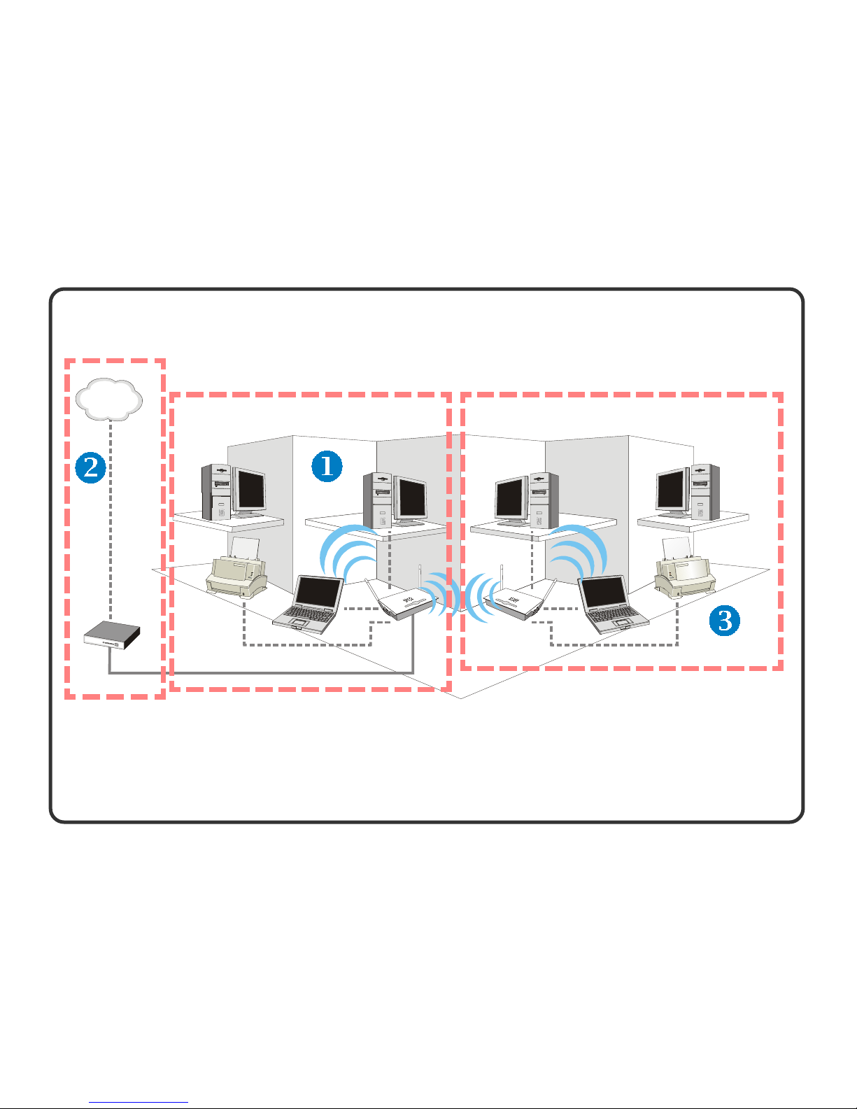
Application of RG54G2 in Your Wireless Network
INTERNET
BSS (Basic Service Set) ESS (Extend Service Set)
4
Page 10

5
>>> 1.3 Features and Benefits
PRISM NitroTM support: enhance performance for 50% greater
throughput in 11g only network and 300% in mixed network coexisting 11g and 11b devices
Enhanced security: authenticate and encrypt with advanced
WPA, 802.1x, AES, TKIP and 64/128-bit WEP
WDS support: extend wireless network coverage by functioning as a bridge
Auto MDI/MDI-X support: simplify wired network setup by
using either standard or crossover CAT-5 cables
Instant-off security button: easy to disable RF access by pushing
a button.
Antenna diversity support: automatically switch association
between two antennae as to receive the best signal quality
Firewall protection: NAT default and SPI option, Access Control List, IP and MAC address filtering
Built-in DHCP server: assign IP addresses to each computer
automatically so there is no need for a complicated networking
setup.
UPnP compatibility: offers seamless operation of voice
messaging, video messaging, games, and other applications that
are UPnP-compliant.
Page 11

6
>>> 1.4 Package Contents
>>> 1.5 System Requirements
After installing the RG54G2, you need the followings to configure respective network settings:
- Laptop or desktop PC with a wireless 11b or 11g client card
installed.
- Microsoft® Windows® 98SE/ME/2000/XP.
- 200MHz or faster processor recommended.
- Internet browser for web-based configuration.
Unpack the package and check all the items carefully. If any
item contained is damaged or missing, please contact your local
dealer immediately. Also, keep the box and packing materials in
case you need to ship the unit in the future. The package
should contain the following items:
- One Wireless 11g Broadband Router - RG54G2
- One AC Power Adapter, 12VDC/1A output
- One Ethernet cable (RJ-45)
- One Quick Start Guide
- One CD-ROM including manual files
Page 12

7
>>> 1.6 Specifications
Wireless Data Rates - IEEE802.11b (auto-fallback)
CCK: 11, 5.5Mbps
DQPSK: 2Mbps
DBPSK: 1Mbps
- IEEE802.11g (auto-fallback)
OFDM: 54, 48, 36, 24, 18, 12, 9, and
6Mbps
Standard Compliance - IEEE802.11g
- IEEE802.11b
- IEEE802.3/802.3u
- IEEE802.3x
Dimension 180 x 127.2 x 32 mm
Antenna Requirement - Peak Gain = 2dBi
- Average Gain = 1.08dBi
(@ 2.45GHz, H-Plan)
Antenna Specification Dual dipole external antennae
LEDs - Power LED x 1
- WAN LED x 1
- LAN LED x 4
- WLAN LED x 1
SDRAM Memory 8MB
Flash Memory 2MB
Power Consumption - Max loading 7W
- Standby Mode 650mA
- Transmit Mode 810mA (RF
Continuous Mode)
General
Hardware
<
_
<
_
<
_
Page 13

8
AGC (Auto Gain Yes
Control)
Antenna Diversity Yes
Channel Frequency - 2.4 ~ 2.4835GHz
- 14 channels
Output Power - 11b Mode: 17 ± 1dBm (before antenna)
- 11g Mode: 13.5 ± 1dBm (before antenna)
Receive Minimum - 54Mbps OFDM @ 10% PER = -67dBm
Input Level Sensitivity - 48Mbps OFDM @ 10% PER = -70dBm
- 36Mbps OFDM @ 10% PER = -75dBm
- 24Mbps OFDM @ 10% PER = -79dBm
- 18Mbps OFDM @ 10% PER = -82dBm
- 12Mbps OFDM @ 10% PER = -84dBm
- 11Mbps CCK @ 8% PER = -82dBm
- 9Mbps OFDM @ 10% PER = -87dBm
- 6Mbps OFDM @ 10% PER = -85dBm
- 5.5Mbps CCK @ 8% PER = -85dBm
- 2Mbps QPSK @ 8% PER = -86dBm
- 1Mbps BPSK @ 8% PER = -89dBm
Throughput - 54Mbps OFDM Throughput > 21Mbps
- 48Mbps OFDM Throughput > 20Mbps
- 36Mbps OFDM Throughput > 17Mbps
- 24Mbps OFDM Throughput > 10Mbps
- 18Mbps OFDM Throughput > 9Mbps
- 12Mbps OFDM Throughput > 5.5Mbps
- 11Mbps CCK Throughput > 5Mbps
- 9Mbps OFDM Throughput > 3.5Mbps
- 6Mbps OFDM Throughput > 3Mbps
- 5.5Mbps CCK Throughput > 2Mbps
- 2Mbps QPSK Throughput > 0.8Mbps
- 1Mbps BPSK Throughput > 0.4Mbps
Page 14

9
Numbers of PCs Up to 253
Supported
Numbers of Ports Four RJ-45 10/100 switched Ethernet ports
Auto Crossover Yes
Detection
Numbers of Ports One RJ-45 port for a Cable/xDSL modem
Management Tools Web-based browser; Event log; Login
password
Auto Crossover Yes
Detection
LAN
WAN
- DHCP Server
- Static IP
- MAC Filter
- uPnP
- Static IP
- DHCP Client
- PPPoE
- PPTP
- Clone MAC
- Radio & Channel setting
- Data Rate
- 64/128 bits WEP
- 802.1x
- WPA
- Wireless Bridge
- Association Control & List
LAN
Software
WAN
Wireless
Page 15

10
Gateway
0 ~ 45OC @ 90% Humidity (non-condensing)
-40 ~ 75
O
C @ 95% Humidity (non-condensing)
Operational Temp.
Environment
Storage Temp.
- NAPT (one to many)
- NAT
- Firewall: Virtual DMZ, IP Filter, ICMP Blocking, DoS, SPI,
VPN pass-through
- DNS Relay
- DDNS
- Remote Management
- Password Management
- Time Zone Management & NTP Client
- Firmware upgradeable
- Status and Statistics
- Event Log
- Email Alarm
- Reset Factory Default
Page 16
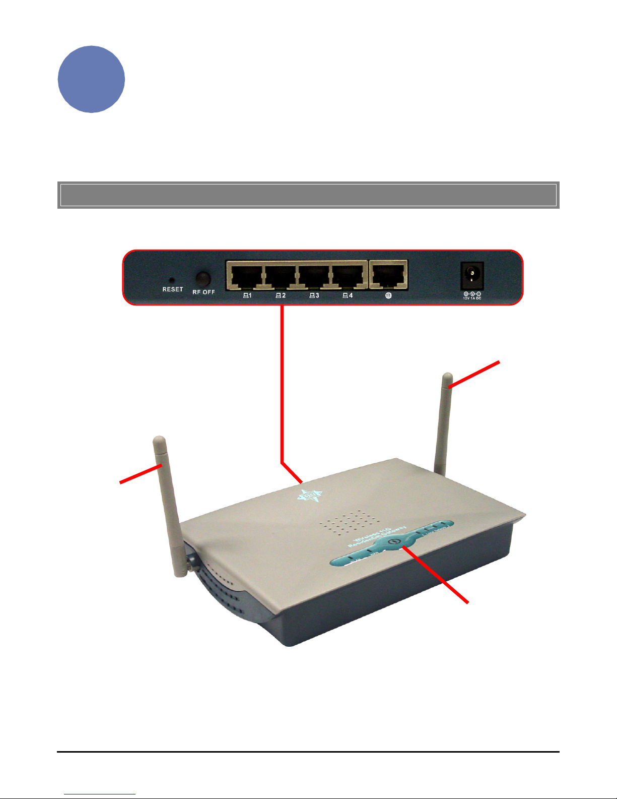
11
This chapter provides a quick introduction on the physical
features of your RG54G2.
Knowing Your Router
>>> 2.1 Product View
RG54G2
Connection Ports
LEDs
Antenna
Antenna
2
Page 17
12
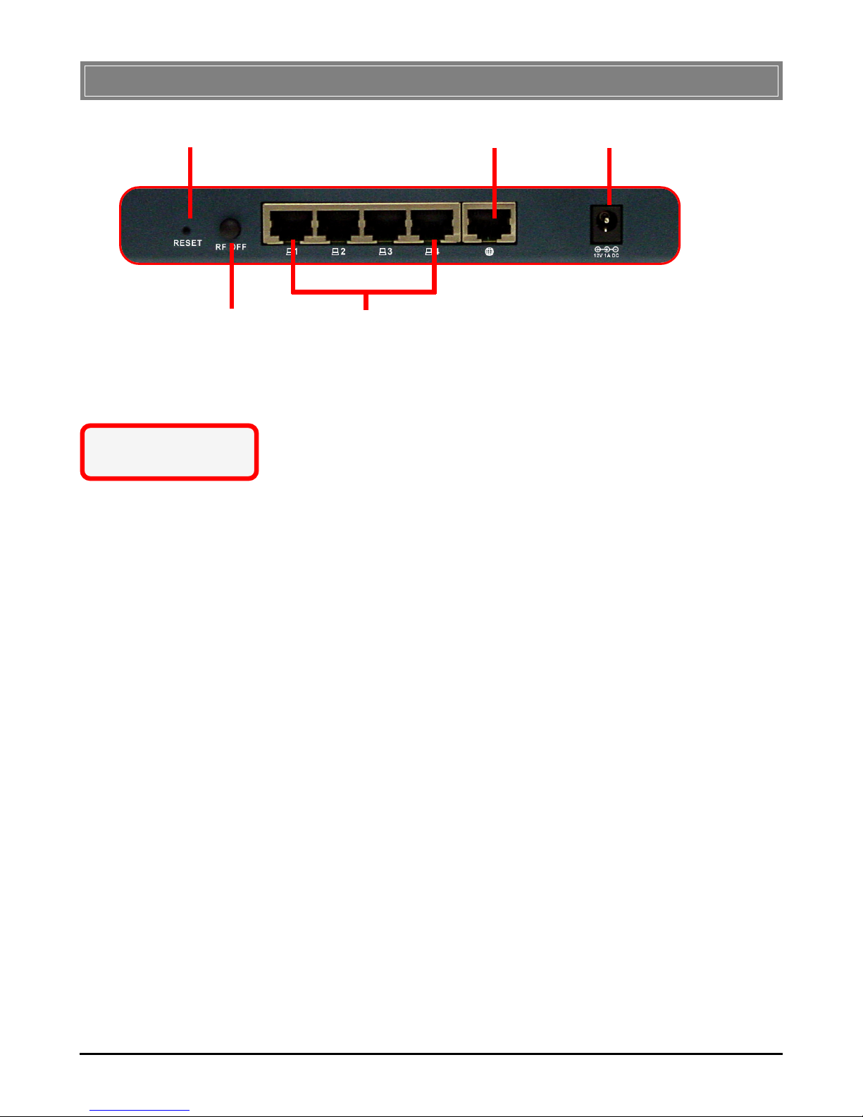
>>> 2.2 Connection Ports
LAN Ports 1~4
RF Off Button
Reset Button WAN Port Power Connector
Reset Button
1. Press and hold* this button longer than 1 second
to restart the router.
2. Press and hold* this button longer than 5 seconds
to reload factory default settings of the router.
RF Off Button
1. Push down this button to turn off RF functionality.
2. Push up this button to turn on RF functionality.
(Default)
LAN Ports 1~4
Those ports are used to connect your computers and other
network devices with auto-sensing.
WAN Port
This port is used to connect your xDSL/Cable Modem for
Internet connection.
Power Connector
This connector is used to connect the enclosed AC power
adapter.
* Use a pointed object
(e.g. a stretched clip)
Page 18

13
>>> 2.3 LEDs
Power
1. Off - no power.
2. Steady Blue - the router is powered up.
LAN 1~4
1. Off - no LAN connection.
2. Steady Green - a computer/device is successfully
connected to the port.
3. Blinking Green - data is transmitted or received over
the port.
WA N
1. Off - no WAN connection.
2. Steady Green - a device is successfully connected to
the port.
3. Blinking Green - data is transmitted or received over
the port.
Wireless Status
1. Off - no wireless connection.
2. Steady Green - a wireless connection is ready.
3. Blinking Green - data is transmitted or received over
wireless network.
Page 19
14
Connecting the Router
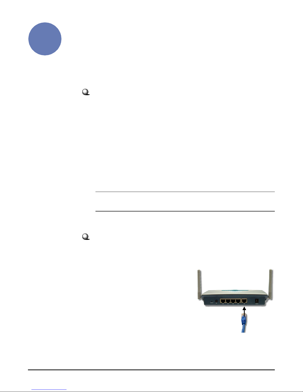
1. Ensure both of your RG54G2 and Cable/DSL modem are
powered off before connecting.
2. Connect one end of an
Ethernet cable to the WAN
port of RG54G2, and the
other end to your Cable/DSL
modem.
Selecting a Location
Before connecting the RG54G2 to your devices, please note the
RG54G2 should be placed in a location where is:
- A flat surface, and do not put any heavy object on it.
- Easy to access; therefore, you can easily connect Cable/
DSL modem to its WAN port and connect computers or
other devices to its LAN ports.
- Easily to read LEDs clearly, so that you may monitor
real-time networking status and take instant measures as
problems arise.
Connecting Your Router
3
Tip: The location of RG54G2 should be the optimum position to obtain
best signal quality; sometimes, you may adjust the direction of antennae.
Page 20
15
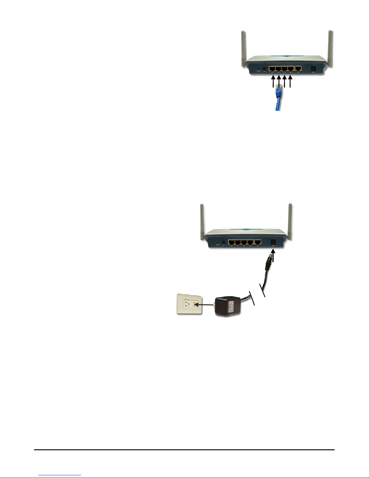
3. To build up wired Internet
connection, plug one end of
another Ethernet cable to the
LAN port (1~4) of RG54G2,
and the other end to your
computers. It does not matter
which numbered LAN port is
chosen.
4. Power on your Cable/DSL modem by turning on power
switch or re-connecting its power adapter.
5. Power up the RG54G2 by plugging the DC end of
power adapter into the power receptor of RG54G2 and
the AC end to an electrical outlet.
6. Verify LEDs on the top panel light up to indicate
proper connection:
- Power LED should be ON to show power
connection
- WAN LED should be ON if your modem is
correctly connected to the router.
- LAN 1~4 LED should be ON correspondent to
the numbered ports your computers are
connecting to.
Page 21

16
4
Configuring Your PC
This chapter details how to configure your Windows clients for
Internet connection through MSI RG54G2 Router.
>>> 4.1 Configuring Windows 98SE/ME
1. Go to Start -> Settings -> Control Panel.
2. Double-click the Network icon.
3. The Network window appears as below. Select
TCP/IP -> (your Wireless LAN adapter model), and
click Properties to bring up the TCP/IP Properties
window.
Select this
Click
Your Wireless LAN adapter model
Page 22

17
4.a To configure a dynamic IP address, choose IP
Address tab and check the Obtain an IP Address
Automatically option.
4.b To configure a fixed IP address, choose IP Address
tab and check the Specify an IP Address option.
Then, enter an IP address into the empty field.
Suggested IP Address Range is 192.168.1.1 to
192.168.1.253, and suggested Subnet Mask is
255.255.255.0.
Check this
Enter a fixed IP address
and Subnet Mask
5. Click OK. Then, click Yes when prompted to reboot
the computer.
4.a Configuring a dynamic IP address
4.b Configuring a fixed IP address
Check this
Page 23
18
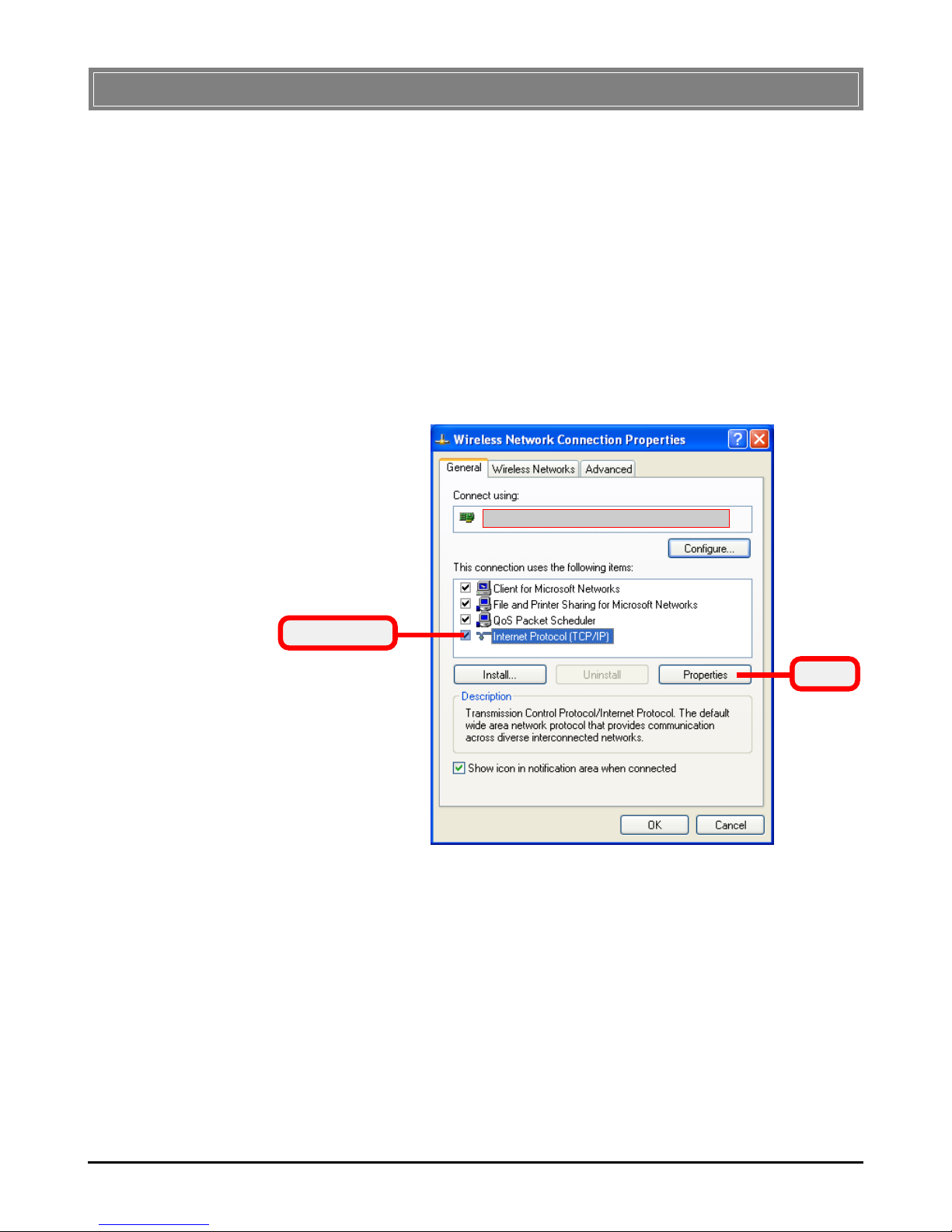
>>> 4.2 Configuring Windows 2000/XP
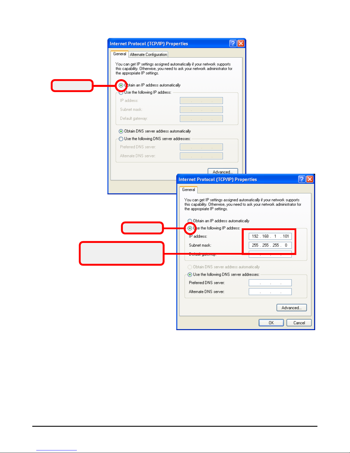
5.a To configure a dynamic IP address, check the
Obtain an IP Address Automatically option.
5.b To configure a fixed IP address, check the Use the
following IP address option. Then, enter an IP
address into the empty field. Suggested IP Address
Range is 192.168.1.1 to 192.168.1.253, and
suggested Subnet Mask is 255.255.255.0.
1. Go to Start -> Settings -> Control Panel.
2. Double-click the Network Connection icon to open
the Network Connection window.
3. Right-click the IEEE802.11g Wireless PCI Adapter
icon and click Properties from the shortcut menu.
4. When the Wireless Network Connection Proper-
ties window appears, choose General tab and select
Internet Protocol [TCP/IP], and click Properties to
bring up the Internet Protocol [TCP/IP] Properties window.
Select this
Click
Your Wireless LAN adapter model
Page 24
19
6. Click OK to complete the configuration.
5.a Configuring a dynamic IP address
5.b Configuring a fixed IP address
Enter a fixed IP address
and Subnet Mask
Check this
Check this
Page 25

20
Configuring Your
Router - Basic
>>> 5.1 Web Configuration Utility
The MSI RG54G2 provides you with a convenient utility to
customize the network settings. Whenever you want to configure
the respective settings, open your web browser (e.g. Internet
Explorer), and type the default IP address 192.168.1.254 in the
Address bar and press [Enter]. When the password page appears,
type admin* in the Password box and click LOGIN.
Click
Enter the Password
Open the web browser and
enter the IP Address of the
router.
5
* admin is the default password setting of the router, and can be
changed in the Configuration Utility. Refer to Section 6.1 for details.
Page 26

21
The Home window of the Configuration Utility will appear as
below, which provides three options to select: Typical
Configuration, Customized Configuration, and Logout.
Home Window of the Configuration Utility
- Typical Configuration: Provides a step-by-step
Setup Wizard to guide you through the basic settings of
the router. Generally, after completing the four steps
in this option, your router can connect to the ISP.
- Customized Configuration: Allows you to customize the network settings of your router for some specific purposes, such as changing password, updating
firmware, and configuring other network settings.
- Logout: Allows you to exit the utility and return to
the login page.
Note: Since the RG54G2 supports DHCP Server and which is enabled
by default, the computer connected to it is automatically assigned a
dynamic IP address that is allowed to enter the Configuration Utility.
Otherwise, you have to assign a fixed IP address to this computer
within the IP address range of the RG54G2. For example, you can
assign a fixed IP address of 192.168.1.253 with a Subnet Mask of 255.
255.255.0
Page 27

22
For a basic network setup, click Typical Configuration in the
Home page. The Setup Wizard will appear to guide you through
Typical Configuration steps one by one. You can return to Home
page by clicking HOME button that is available in every page of
the Utility, or exit the Utility by clicking Logout whenever you
want.
The Menu Bar
>>> 5.2 Typical Configuration
STEP
11
11
1
Click Next to continue Step 2.
Setting the Time Zone
First, you should choose your Time Zone from the pull-down
menu. For system management purpose, a correct time zone
setting will let you have accurate time stamps on the system log.
If you are in the area within the daylight saving period, please
also check the Daylight Saving option.
Step 1. Setting the Time Zone
The Menu Bar
Choose your
Time Zone.
On each screen,
click "Help" button
will bring up a help
window.
Page 28

23
STEP
22
22
2
Setting the Connection Type
According to the connection type your ISP provides, select an
appropriate option.
Choose your
Connection Type.
Cable Modem: If your broadband access is through a cable
modem, or if your ISP supports DHCP (Dynamic Host Configuration Protocol), select this type.
Fixed IP XDSL: If your broadband access is through an xDSL
modem and use a fixed IP address, select this type.
xDSL-PPPoE: If your broadband access is through an xDSL
modem and use PPPoE (Point-to-Point Protocol over Ethernet),
select this type. The IP address is usually allocated automatically.
xDSL-PPTP: If your broadband access is through an xDSL
modem and use PPTP (Point-to-Point Tunneling Protocol), select this type. The service is used mostly in Europe.
BigPond Cable: If your broadband access is through BigPond
Cable, select this type. The service is used in Australia only.
Page 29

24
STEP
33
33
3
Setting the Connection Type (continued)
Based on the preceding selection, you will be further asked for
different configuration settings.
Cable Modem: If you are required by ISP to use a particular
Host Name or MAC Address, enter the data into the fields
accordingly. Mostly, leave them blank will work. Click Next to
continue.
Fixed IP xDSL: Fill in the data provided by your ISP in the
fields of IP, Subnet Mask, Default Gateway, and DNS
(Domain Name Server), followed by clicking Next to continue.
Page 30

25
xDSL-PPPoE: Fill in the data in the User Name and Password
fields, which are supplied by your ISP. Optionally, you might
need to specify Service Name if your ISP provide it; otherwise,
leave that field blank. Click Next to continue.
xDSL-PPTP: Fill into the required fields with the data supplied by your ISP. Then click Next to continue.
- User Name: the user name of your ISP account.
- Password: the password of your ISP account.
- Confirmed Password: re-enter your ISP account pass-
word.
Page 31

26
- Service IP Address: the IP address on remote side of
PPTP tunnel supplied by your ISP.
- My IP Address: the IP address on local side of PPTP
tunnel supplied by your ISP.
- My Subnet Mask: the Subnet Mask on local side of
PPTP tunnel supplied by your ISP.
BigPond: Fill into the required fields with the data supplied
by your ISP. Then, click Next to continue.
- User Name: the user name of your ISP account.
- Password: the password of your ISP account.
- Confirmed Password: re-enter your ISP account
password.
- Host Name: the host name of your router. Some ISPs,
usually cable ISPs, require the host name as
identification. In most cases, leaving it blank will work.
- Auth Server: select your state from the pull-down
menu. This will automatically fill in your login Server
IP Address in the last field.
- Manual Server: if you are in the state that is not listed
in the menu here, select Enable in this field and type in
the Server IP Address in the next field.
- Server IP Address: the IP address of BigPond server
supplied by your ISP.
Page 32

27
STEP
44
44
4
Configuring the Wireless Network Settings
You will now see two basic wireless settings: SSID and Channel.
- SSID: SSID (Service Set Identifier) is the network
name (by default: RG54G2). It is case-sensitive and
must not exceed 32 characters. To communicate, all
wireless devices in the network should share the same
SSID.
- Channel: Select the channel in the pop-up menu (by
default: 7). All wireless devices in the network must be
set at the same channel. If you are running into interference problem, you may need to experiment on different
channels to see which channel is of the best signal
quality.
Click Next to continue.
STEP
55
55
5
Summary
In this last step in Typical Configuration, a summary page appears to show you all configurations you have set. Click Finish
to complete your basic network set up.
After clicking Finish, you are brought to Home page. You may
select Logout to exit or select Customized Configuration continuing to more advanced configuration settings.
Setting SSID
and Channel.
Page 33

28
Although your RG54G2 Broadband Router will function fine
using the Typical Configuration from Chapter 5, you may
wish to explore more advanced options. This chapter explains each parameter and setting procedures for advanced
network setup.
Click Customized Configuration in the Home window, and
the main window appears as below. You can return to Home
page by clicking HOME button that is available in every page of
the Utility, or exit the Utility by clicking Logout whenever you
want.
Main Window of Customized Configuration
The Menu Bar
Configuring Your
Router - Advanced
6
The Customized Configuration is divided into six tabs: System,
Internet, LAN, Wireless, NAT, and Firewall. Each tab pro-
vides you access to advanced feature settings, and is explained
details in the following sections.
Page 34

29
Click System tab on the main menu to reach the screen as
below, which lists a submenu of all advanced features relating
to general system settings.
> Time Zone
Select Time Zone from the drop-down menu. For system management purpose, a correct time zone setting can provide accurate time stamps on the system log. If you are in an area within
daylight saving period, please also select Enable in the Daylight
Saving option as to automatically adjust for daylight saving time.
Click Apply to save your changes, or click Cancel to abandon
your changes.
This window includes:
> Time Zone
> Password Setting
> Remote Management
> Firmware Upgrade
> Restart
> Factory Default
> System Status
> Statistics
> Event Log
> Diagnostic
> Use as Access Point
> Backup Settings
>>> 6.1 System Settings
On each screen,
click "Help" button
will bring up a help
window.
Page 35

30
> Password Setting
- Password: This option allows you to change the default
password. The RG54G2 router is shipped with the default
password admin. To change the setting, enter the old password followed by the new password twice.
- Authentication Expire: This option allows you to change
your login idle time, which is the amount of idle time that
elapses before the router automatically logs off the user. Select Enable to turn on this function or Disable to turn it off.
Specify your preferred duration of idle time into Expire Time
field (by default: 10 minutes).
Click Apply to save your changes, or click Cancel to abandon
your changes.
> Remote Management
The remote management screen allows you to log into your
RG54G2 router remotely via Internet. To enable remote access,
select Enable (by default: Disable) in Remote Management
field. Then, specify the port number (by default: 8080) that will
be open to remote access in Remote Management WAN Port
field.
Page 36

31
> Firmware Upgrade
This screen enables you to update the firmware.
1. Download the latest firmware file to your computer
from MSI website.
2. Click Browse button to locate your latest firmware file.
3. Click Upgrade button to upgrade your RG54G2 router
with the selected file.
4. You are prompted with a dialogue window. Click OK
to go on the firmware upgrade or Cancel to abandon it.
5. A dialogue window appears to reveal the upgrade is
going on. Please wait and you will be brought to login
page as soon as the upgrade is completed.
Page 37

32
2. A dialogue window appears to reveal the rebooting is
going on. Please wait and you will be brought to login
page as soon as the rebooting is done.
> Factory Default
In addition to press RESET button for five seconds, this screen
allows you to reset all configuration settings into factory default
values via Utility.
1. Click Restore button to initiate your router restoring.
2. You are prompted with a dialogue window to make
certain your intention in restoring factory default.
Click OK to go on or Cancel to abandon.
> Restart
In addition to press RESET button for one second or unplug the
power adapter, this screen provides you with another way to
restart your RG54G2 router in the case you are unable to reach
the hardware.
1. Click Restart button to initiate your router rebooting.
Page 38

33
3. A dialogue window appears to reveal the restoring is
going on. Please wait and you will be brought to login
page as soon as the restoring is done.
> System Status
The System Status screen displays the router’s all configuration
settings, containing respectively in General, Internet, LAN, and
Wireless setting tables. Click Refresh to reload your router’s
most updated status data.
In the column of WAN IP Address, there are two buttons: Re-
lease and Renew. If you are using a Dynamic IP address connecting to Internet, you can click Release to break your Internet
connection and release IP address, or click Renew to retrieve a
new IP for your connection.
> Statistics
This Statistics screen displays all necessary statistics of the
RG54G2 router, providing you a full monitoring and control of
this router’s performance. Click Refresh to reload your router’s
most updated statistics data.
> Event Log
The Event Log screen records the last 128 events (network
activities) that occur on your RG54G2 router. This data is
useful for monitoring and troubleshooting your network, but
recording a big volume of logs might adversely affect the router’s
performance.
Page 39

34
- Save button: Since only a limited of system log entries
can be stored in RG54G2 router, you can save the log file
into your computer by clicking this button.
- Clear button: You can remove all bug entries from your
RG54G2 router by clicking this button.
- Refresh button: You can update the bug entry record by
clicking this button.
> Diagnostic
This Diagnostic screen provides you with two ways to check
your network connections.
- Ping: Enter into the field with the IP address of the
device you would like to ping. The device could be
either on LAN or on the Internet; then, click Ping button
to initiate Ping procedure. The results will be displayed
in the following pop-up window.
- Connection: Click the Test Connection button to start
trying to access the Internet through your router.
Page 40

35
2. A dialogue window appears to reveal the configuration
is resetting. Please wait and you will be brought to
login page as soon as the resetting is done.
> Use as Access Point
MSI RG54G2 Broadband Router could be configured into Access Point mode, only acting as a bridge between the computers
attached to all Ethernet ports (LAN) and the clients on the wireless LAN (WLAN). To operate at AP mode, your RG54G2 has
to be configured to share the same subnet mask as other LAN and
WLAN devices.
1. Check the Enable AP Mode option. Click Apply to
save your changes or Cancel to abandon the changes.
At AP mode, the internal NAT, Firewall, and DHCP server will
be disabled; one WAN port and four LAN ports are bridged
together. The menu bar turns out to appear with only two tabs:
System and Wireless.
Page 41

36
> Backup Settings
This option allows you to save the current configuration profile
of your RG54G2 router onto your computer. In time of need,
you can restore an earlier profile onto your RG54G2 router.
- Save Settings: Click Save to download a copy of cur
rent configuration profile and save that file to your
computer.
- Restore Settings:
1. If you want to restore an earlier configuration profile
back to the RG54G2 router, click Browse to select the
file you want, followed by clicking Restore to upload
the configuration file.
2. You are prompted with a dialogue window to make
certain your intention in restoring the profile. Click
OK to go on or Cancel to abandon.
3. Following is the dialogue window reveals the restoring
is going on. Please wait and you will be brought to
login page as soon as the restoring is done.
Page 42

37
This window includes:
> Connection Type
> MAC Clone
> DNS
> Dynamic DNS
>>> 6.2 Internet Settings
Click Internet tab on the main menu to reach the screen as
below, which lists a submenu of all advanced features relating to
Internet settings.
Click each item in the submenu and follow the instructions to
manage advanced Internet settings of your RG54G2 broadband
router.
> Connection Type
This screen provides you with a selection of Internet connection
types. According to the connection type your ISP provides,
select an appropriate option.
For detailed instructions on how to set your connection type,
please refer to Step 2 and Step 3 in Section 5.2.
Page 43

38
> MAC Clone
A MAC address is a 12-digit code assigned to a unique piece of
hardware for identification. You can find the MAC address of
your RG54G2 router on the label on its bottom case.
The MAC Address on this screen refers to the address on the
Internet (WAN) interface. If you need to provide your ISP with
a MAC address for registration, provide the default MAC address indicated on the label.
If you have already registered a MAC address in your ISP, you
can change your RG54G2 router’s MAC address to match the
address recorded by your ISP.
1. Enter the MAC address into the MAC Address field
that is registered in your ISP.
2. Click Clone MAC Automatically button. Next, click
Apply to actually change the address used or Cancel to
abandon the change.
Sample of MAC
address.
Page 44

39
> Dynamic DNS
MSI RG54G2 router supports Dynamic DNS (DDNS) feature,
which allows you to assign a fixed host and domain name to a
dynamic Internet IP address. Each time the MSI RG54G2 router
is booted, it will re-register its domain-name-to-IP-address
mapping with DDNS service provider. This is the reason Internet
users can access your router using the domain name, but not the
IP address.
Note: Before using this feature, you need to sign up for DDNS service
with service providers.
> DNS
MSI RG54G2 router offer DNS (Domain Name System) feature.
DNS is able to translate Internet domain names to IP addresses.
This DNS screen can be used to add the mappings between a
Private Static IP and a Domain Name. Such a feature is helpful
for setting up devices like FTP server.
1. Enter Domain Name and Private IP into the respective fields.
2. Click Add to apply the setting. Then, the data entry
will appear in the below DNS table.
3. Click Delete if you want to remove the data entry from
the table.
Page 45

40
1. First, check Enable in the Dynamic DNS field to
activate the feature.
2. Select your Dynamic DNS Provider in the drop-
down menu.
3. Enter the Host Name that you are used to register
with your DDNS provider.
4. Enter your User Name that is required to log into
your DDNS account.
5. Enter your Password that is required to log into your
DDNS account.
6. My IP Address is showing your router’s current IP ad
dress assigned.
7. Click Update Now button if you want to remove the
original settings. Otherwise, skip this field.
8. Status field displays the status of DDNS connection,
which is returned by DDNS server.
Click Apply to save the DDNS settings, or Cancel to abandon the
settings.
Page 46

41
Click LAN tab on the main menu to reach the screen as below,
which lists a submenu of all advanced features relating to LAN
settings.
This window includes:
> IP Setting
> DHCP Server
> DHCP IP-MAC mapping
> DHCP Client List
> MAC Filter
> UPnP Setting
>>> 6.3 LAN Settings
Click each item in the submenu and follow the instructions to
manage advanced LAN settings of your RG54G2 broadband
router.
> IP Setting
This option allows you to create your own private network.
1. Enter an IP address string that you will use for your
private network, you can choose any string you prefer.
(By default: 192.168.1.254)
2. Enter a Subnet Mask address that you will use for
your network. (By default: 255.255.255.0)
Page 47

42
> DHCP Server
A DHCP (Dynamic Host Control Protocol) server automatically
assigns IP address to all the clients on your network. This screen
allows you to configure the DHCP server settings of your
RG54G2 router.
1. Check Enable option to enable DHCP function in
your RG54G2 router. If you already have a DHCP
server running on your network or you do not want to
enable it, select Disable option.
2. Specify a numerical value in IP Pool Starting Address
field as the first address being assigned by DHCP
server. (By default, it is 192.168.1.1.)
3. Specify a numerical value in IP Pool Ending Address
field as the last address being assigned by DHCP
server. The numbers from 1 to 253 are available for
use. (By default, it is 192.168.1.32.)
4. Specify a numerical value in Lease Time field to
define the lease duration a network user will be
allowed connecting to the router with their current
dynamic IP address.
Click Apply to save the changes, or Cancel to abandon.
Page 48

43
> DHCP IP-MAC Mapping
If you require specifying an IP address for a certain network
device, you can use this feature to create a mapping table.
1. Enter a specific IP Address you like to reserve and the
MAC Address of that device’s network card.
2. Following by pressing Add button.
3. The reserved IP address along with its associated MAC
address is displayed in Current Settings field.
4. You can add more reservations, or click Delete to
remove the correspondent entry.
> DHCP Client List
This screen is used to show you the current clients on your
network that have been assigned IP addresses by your RG54G2
DHCP server.
Click Refresh to obtain an updated list, or click Release to delete
a certain client from the list or Release All to delete the entire
listed clients.
Page 49

44
> MAC Filter
This option enables you to define a list of MAC addresses,
controlling which device is permitted to access to your network.
Select one rule from LAN MAC Filter Control field:
1. Disable: Select to disable MAC Filter function if you
do not want to filter users by MAC address. Or,
2. Allow: Select to allow only the devices in the MAC
Address list to access to your network. Or,
3. Deny: Select to deny the devices in the MAC Address
list to access to your network.
Click Apply to save your changes after selecting a rule.
To add a MAC Address to your list:
1. Enter a MAC Address into the field.
2. Click Add to add the entry to the MAC Address List.
3. Click the Delete button next to the desired MAC
address to remove it from the list.
Select one entry.
Page 50

45
> UPnP Setting
UPnP (Universal Plug-and-Play) is a technology that offers seamless operation of voice messaging, video messaging, games, and
other applications that are UPnP-compliant. Those applications usually require the router’s firewall to be configured a specific way to operate properly. With UPnP support, those applications have the ability to communicate with router, basically
“telling” the router which way it needs the firewall configured.
1. UPnP Service:
Enable Turn on UPnP function in RG54G2.
Disable Turn off UPnP function in RG54G2.
2. UPnP Internet Gateway Device Status:
Enable PC will keep polling router’s status and
display packet information. Be noted, this will
increase network loads, affect router’s
performance, and have a compromized
security.
Disable PC will not poll router’s status and no packet
information is displayed. No extra loads on
your network.
3. UPnP Internet Gateway Device Control:
Enable The PC running with UPnP application is
allowed to configure the settings of your
router.
Disable The PC running with UPnP application is
blocked to configure the settings of your router
if any security concern.
Page 51

46
>>> 6.4 Wireless Settings
Click Wireless tab on the main menu to reach the screen as
below, which lists a submenu of all advanced features relating to
Wireless settings.
This window includes:
> SSID & Channel
> Radio Setting
> Authentication &
Encryption
> Wireless Bridge
> Associated Client List
Click each item in the submenu and follow the instructions to
manage advanced Wireless settings of your RG54G2 broadband
router.
> SSID & Channel
In this screen, you can make changes to your SSID and Channel.
Page 52

47
1. SSID: SSID (Service Set Identifier) is the network
name (by default: RG54G2). It is case-sensitive and
must not exceed 32 characters. To communicate, all
wireless devices in the network should share the same
SSID.
2. Channel: Select the channel in the pop-up menu (by
default: 7). All wireless devices in the network must be
set at the same channel. If you are running into
interference problem, you may need to experiment on
different channels to see which channel is of the best
signal quality. The settings of Channel 1, 6 and 11 are
non-overlapping.
3. Accept Broadcast SSID: Check this option if you
want to broadcast your router’s SSID, which enable all
the devices on your network to detect the SSID
broadcast by the RG54G2 router. Remove the check
mark if you do not want to broadcast your router’s
SSID.
Click Apply to save the setting, or Cancel to cancel the changes.
> Radio Setting
This screen is used to set up your router’s advanced radio features.
If you do not know how to configure these parameters, we recommend you keep the default values preventing from impacting
on your router’s performance.
Page 53

48
1. Beacon Period (TUs, Time Units): The default value
is 100 milliseconds. This value refers to the frequency
interval that your router broadcasts a beacon to syn chronize the wireless network. As broadcasting beacon
do use additional bandwidth, lowering beacon period
too much might adversely affect the wireless
performance.
2. RTS Threshold (0-2347): The default value is 2347
bytes. This value refers to the packet size at which the
router issues an RTS (Request To Send) frame to a
receiving wireless station. Any frames larger than
specified RTS threshold must be transmitted following
the RTS/CTS handshake exchange mechanism. After
receiving an RTS, the wireless station responses with a
CTS (Clear To Send) frame to acknowledge the right to
begin data transmission. The RTS/CTS mechanism is
used to minimize collisions among wireless stations.
3. Fragmentation Threshold (800-2346): The default
value is 2346 bytes. This value refers to the size at
which a packet is divided into smaller pieces that are
transmitted separately to receiving wireless station. If
there is a high packet error rate, you may need to
experiment on different fragmentation values to find
the best performance.
4. DTIM Period (1-255): The default value is 1 beacon
period. This value refers to the time interval at which
the router broadcasts a DTIM (Delivery Traffic
Indication Message) to inform clients in power saving
mode to wake up for listening to broadcast and
multicast messages.
5. Mode: The default wireless mode is Auto. If you have
both 11b and 11g clients on your network, keep the
factory default mode, Auto. You can also select 802.
11g Only mode from the pull-down menu if you want
to prevent 11b clients accessing to your network, or
802.11b Only mode if you want to work with 11b
clients only.
Page 54

49
6. Basic Rate: The default rate is Default. The Basic
Rate is not the same as the Transmission Rate, but a
series of rates that the router broadcasts to clients to
make them aware of over what rate they can transmit.
With Default Basic Rate, the router will broadcast that
it will automatically transmit at the best rate. You can
also select another option (1,2,5.5,11,6,12,24Mbps) to
broadcast only slower rate available.
7. Transmit Rate: The default rate is Auto. With the
default setting, your router will enable Auto-Fallback
feature and automatically select the best possible data
rate for transmission. From the pull-down menu, a
range of other fixed transmission rates are also
selectable.
8. PRISM NitroTM: The default is Disable. Enabling this
NitroTM mode should improve your network
performance, either 3 times faster data rates in mixed
environment where both 11g and 11b clients exist, or
50% more data throughput in 11g-only environment.
Click Apply to save the setting, or Cancel to cancel the changes.
> Authentication & Encryption
This feature enables you to manage your wireless network security with different authentication and encryption methods.
Authentication Encryption WEP key 1~4
Open or shared key None Not required
WEP-64 bits 10 hex
WEP-128 bits 26 hex
Shared key WEP-64 bits 10 hex
WEP-128 bits 26 hex
WPA TKIP Not required
802.1x None Not required
WEP-64 bits 10 hex
WEP-128 bits 26 hex
Page 55

50
Method 1:
1. Select Both from the drop-down menu of Network
Authentication field. With this setting, your router
will switch between two authentication subtypes,
Open and Shared Key, based on your client’s
request.
- Open: Under this, it allows any wireless stations to
access to the router without asking a shared secret key,
but the wireless station can communicate only if its
WEP key matches with the router’s.
- Shared Key: It works only if the WEP Key option
is on. It requires a wireless station providing a shared
key to be authenticated by the router. Once its shared
key is proved as correct, the wireless station is allowed
to communicate with the router.
2. Select None from the drop-down menu of Encryption
Type field. With this setting, no encryption mecha-
nism is enabled.
Example 1: Authentication - Both, Encryption - None.
Or,
3. Select WEP from the drop-down menu of Encryption
Type field. With WEP enabled, you can further choose
low-level (64-bit) or high-level (128-bit) encryption
schemes for each of your encryptions keys. It is
possible to enter up to four (4) WEP Keys.
- 64-bit WEP Key: Under this, it allows you to
manually enter five (5) digits of alphanumeric
characters, ex. “1gmi4”.
Page 56

51
- 128-bit WEP Key: Under this, it allows you to
manually enter thirteen (13) digits of alphanumeric
characters, ex. “1k8gf40kj1”.
Click Apply to save the settings, or Cancel to cancel the changes.
Example 2: Authentication - Both, Encryption - WEP.
Page 57

52
Method 2:
1. Select Shared Key from the drop-down menu of
Network Authentication field; then your router will
use shared key mechanism to process all authentication
requests.
2. WEP encryption is automatically enabled.
3. Enter your 64-bit or 128-bit WEP keys into the entries.
Click Apply to save the settings, or Cancel to cancel the changes.
Example 3: Authentication - Shared Key, Encryption - WEP.
Page 58

53
Method 3:
1. Select 802.1X from the drop-down menu of Network
Authentication field, only if there is a Radius Server
on your network for centralized authentication. It is
typically used in business environment.
2. Enter into RADIUS Server IP field with IP address of
the Radius server used for 802.1x wireless
authentication.
3. Enter port number into RADIUS Server Port field.
The default is 1812.
4. Enter the RADIUS Server Key twice for
confirmation. The key is shared between the Radius
server and your router.
5. Select None not to enable WEP function.
Example 4: Authentication - 802.1X, Encryption - None.
Or,
6. Select WEP to enable WEP function; then, set the
encryption level and the WEP Keys.
Page 59

54
Click Apply to save the settings, or Cancel to cancel the changes.
Example 5: Authentication - 802.1X, Encryption - WEP.
Page 60

55
Method 4:
1. Select WPA from the drop-down menu of Network
Authentication field, only if there is a Radius Server
on your network for centralized authentication. WPA
(WiFi-Protected Access) is typically used in business
environment.
2. Enter into RADIUS Server IP field with IP address of
the Radius server used for WPA authentication.
3. Enter port number into RADIUS Server Port field.
The default is 1812.
4. Enter the RADIUS Server Key twice for
confirmation. The key is shared between the Radius
server and your router.
5. Enter a numerical value into WPA Group Rekey
Interval, which specifies the time duration (in
seconds) after which your router changes a new group
key. The default is 3600.
6. TKIP feature in Encryption Type field is automati-
cally selected.
Click Apply to save the settings, or Cancel to cancel the changes.
Example 6: Authentication - WPA, Encryption - TKIP.
Page 61

56
> >
> >
> Wireless Bridge
Wireless Bridge (also known as WDS, Wireless Distribution
System) allows you to extend the range of your network infrastructure by connecting RG54G2 with each other wirelessly. It
offers you great flexibility to configure your network in numerous ways.
- WDS: Star Topology (Figure 1.)
In this star topology, an RG54G2 router acts as a central
point and talks with several other RG54G2 routers as
depicted below. The satellite RG54G2 routers are positioned to extend the wireless range, and each of them can
serve their own wired and wireless infrastructure network.
- WDS: Chain Topology (Figure 2.)
In this chain topology, the satellite RG54G2 routers are
chained together starting from a root RG54G2 router as
illustrated below.
Note: All RG54G2 routers in Wireless Bridge mode must be set at the
same channel as to communicate with each other.
Note: An RG54G2 router in Wireless Bridge mode can maintain up to
four different wireless connections to other routers.
Method 5:
Example 6: Authentication - WPA-PSK, Encryption - TKIP.
Page 62

57
RG54G2
RG54G2
RG54G2
RG54G2
INTERNET
Cable/DSL Modem
RG54G2
RG54G2
RG54G2
RG54G2
INTERNET
Cable/DSL Modem
Figure 1. Star Configuration
Figure 2. Chain Configuration
Page 63

58
> Association Client List
This screen displays a list of wireless stations, which are associated with your RG54G2 router, by their MAC addresses. Click
Refresh to update the list.
To configure the WDS settings of your RG54G2 routers,
1. Select Enable in Wireless Bridge field if you want
your RG54G2 router performs as a bridge/repeater.
2. Check Enable in WDS Only field if you want set up
this router dedicatedly connecting with only other
routers. (Wireless clients are not allowed to associate
with it.) Otherwise, remove check from the box.
3. Click Apply to save the settings, or Cancel to cancel
the changes.
4. Enter MAC Addresses of other RG54G2 routers that
are allowed to talk with this RG54G2 router as
partners in the WDS network.
5. Click Add button to add the specified MAC Address
into the WDS MAC Address list. Click Delete
whenever you want to remove a specified device.
Page 64

59
>>> 6.5 NAT Settings
Click NAT tab on the main menu to reach the screen as below,
which lists a submenu of all advanced features relating to NAT
settings. NAT (Network Address Translation) translates multiple private IP address to single public IP address.
This window includes:
> Static NAT Setting
> Virtual Server
> Special Applications
Click each item in the submenu and follow the instructions to
manage advanced NAT settings of your RG54G2 broadband
router.
> Static NAT Setting
This option allows you to configure your router’s virtual server
setting based on IP forwarding. With IP forwarding setting, all
Internet requests for a specified public IP will be forwarded to a
certain PC with the correspondent private IP.
Page 65

60
1. Input a Private IP, ex. 192.168.1.251, and a Public IP,
ex. 213.18.18.253, into the respective fields.
2. Click Add button to continue.
3. Your new data entry will be displayed in the Current
Settings list. Click Delete if you want to remove it.
> Virtual Server
This option allows you to configure your router’s virtual server
setting based on Port forwarding. Virtual Server feature helps
you set up a server on your private network accessible by Internet
users. With port forwarding setting, all Internet requests for a
specified public IP, based on their ports, will be forwarded to a
certain PC with the correspondent private port.
To choose a known server:
1. You can select a Popular Server (ex. HTTP, Net-
Meeting, POP3 etc.) from the drop-down menu. All
fields except Private IP are automatically filled in data.
2. Specify the IP address of your PC into Private IP field.
3. Click Add button to continue.
4. Your new data entry will be displayed in the Virtual
Server list. Click Delete if you want to remove it.
To choose a custom server:
1. Service Name: Manually define a name for the server
you want to configure.
Page 66

61
2. Private IP: Manually input a private IP address for
your server
3. Start Private Port: Manually enter a private port
number, where the forwarded requests will arrive at.
4. Type: Select from the drop-down menu of either TCP
or UDP protocol
5. Start Public Port: Manually enter a public port
number, the requests from which should be forwarded.
6. Number of Ports: Manually enter the number of ports
setting for virtual server.
7. Click Add button to continue.
8. Your new data entry will be displayed in the Virtual
Server list. Click Delete if you want to remove it.
> Special Applications
This option is used for special applications, such as instant
messaging or some Internet games, whose outgoing ports should
differ from incoming ports.
Commonly, you run a PC application to access the Internet. It
typically initiates communications with a computer on the
Internet. In some special applications, the computer on the
Internet also initiates communications with your PC. If you use
such applications through a PC behind your router, you need to
configure your router to support Port Triggering as to perform
those special applications in proper manner.
To choose a known application:
1. You can select a Popular Application (ex WarCraft)
from the drop-down menu. All fields are automatically
filled in data.
2. Click Add button to continue.
3. Your new data entry will be displayed in the Special
Applications list. Click Delete if you want to remove
the entry.
Page 67

62
To choose a custom application:
1. Trigger Port: Manually specify the range of the port
numbers used by your application, opened for
outbound data. Check the instructions in your
application’s user manual.
2. Trigger Type: Select UDP, TCP, or Both for the
Trigger Port.
3. Public Port: Manually specify the range of the port
numbers used by your application, opened for
inbound data. Check the instructions in your application’s user manual.
4. Public Type: Select UDP, TCP, or Both for the
Public Port.
5. Click Add button to continue.
6. Your new data entry will be displayed in the Special
Applications list. Click Delete if you want to remove
the entry.
Page 68

63
This window includes:
> Basic Setting
> Service Filters
> Polices
> Notification
> Virtual DMZ
Click Firewall tab on the main menu to reach the screen as
below, which lists a submenu of all advanced features relating to
Firewall settings.
>>> 6.6 Firewall Settings
Click each item in the submenu and follow the instructions to
manage advanced Firewall settings of your RG54G2 broadband
router.
> Basic Setting
This screen helps you configure basic rules of the firewall equipped
with your router.
Page 69

64
1. Firewall Protection:
High Check High box only if your broadband
bandwidth is > 2Mbps. It protects your
network in high-level security, yet causes
heavy network loads on your router.
Low Check Low box if your broadband bandwidth
is < 2Mbps. It protects your network in lowlevel security, yet causes only small network
loads on your router.
Disable Check Disable box to turn off the firewall
function, if needed.
2. Inbound Traffic:
Pass Check Pass box if all inbound traffic is
permitted.
Deny Check Deny box if all inbound traffic is denied.
3. Outbound Traffic:
Pass Check Pass box if all outbound traffic is
permitted.
Deny Check Deny box if all outbound traffic is
denied.
4. ICMP Error Message:
Pass Check Pass box if all ICMP error messages are
permitted.
Deny Check Deny box if all ICMP error messages
are denied.
5. WAN ICMP Blocking:
Pass Check Pass box to allow ICMP packets
received from the Internet.
Deny Check Deny box to ignore ICMP packets
received from the Internet.
Page 70

65
Your configuration of the firewall will be displayed in the below
Basic Setting List, depending on the parameters you set in the
preceding steps.
> Service Filters
This screen provides you with the ability to add custom service
filters, up to 32 entries, which are not listed in the Well-Known
Services list and are pre-set in your RG54G2 router already.
To define a custom filter:
1. Specify Name of the custom service filter.
2. Input port number in either TCP Port field, or UDP
Port field, or in both fields.
3. Enter a short description of the service in Descriptions
field.
4. Click Add button to add the new entry, which will be
displayed in Custom Services table.
Page 71

66
To modify a defined custom filter:
1. Click Service Name field of that particular custom
service filter; then, the current entry data is automatically shown on Service Filter screen.
2. Change data into the necessary fields.
3. Click Edit button to confirm your changes; then the
corresponding data entry in Custom Services list will
be changed accordingly.
> Policies
This option allows you to define different firewall polices, up to
32 entries, to control and monitor any inbound and outbound
packets on your network.
To define a WAN to LAN policy:
1. Select WAN to LAN from the drop-down menu of
Direction field. Here, WAN to LAN is defined as
Inbound data control policy.
2. Enter a descriptive name in Policy Name field.
3. Select the service you want to configure from Avail-
able Services list, and click “>” button to transfer it
to Selected Services list. (To remove a service from
Selected Services list, select it and click “<” button to
return it back to Available Services list.) This determines which packets are covered by this rule.
Page 72

67
5. Select from the drop-down menu of Source IP field.
This defines the packets from which sources are
covered by this policy based on their source IP(WAN)
addresses.
Any Select Any if all WAN IP addresses
should be covered by this policy.
Single Select Single if only a specific IP
address is covered by this policy.
Enter that required WAN IP address
into the following blank box.
Range Select Range if a range of IP address is
covered by this policy. Enter the range
of WAN IP addresses into the
following blank boxes.
4. Select the desired action covered by this policy in
Policy Action field.
Deny Check Deny option to block the data
that meets the selected settings.
Pass Check Pass option to permit the data
that meets the selected settings.
Page 73

68
6. Select from the drop-down menu of Destination IP
field. This defines the packets to which PCs or
servers are covered by this policy based on their
destination IP (LAN) addresses.
Any Select Any if all LAN IP addresses
should be covered by this policy.
Single Select Single if only a specific IP
address is covered by this policy.
Enter that required LAN IP address
into the following blank box.
Range Select Range if a range of IP address is
covered by this policy. Enter the
range of LAN IP addresses into the
following blank boxes.
7. Select the time plan in Take Effect field as to
designate when to execute the firewall policy.
Always Select Always to execute the firewall
policy every day.
Schedule Select Schedule to set your desired
time duration of executing the policy.
Following is to select the desired days
of a week in Day field and designate a
specific time period in Time field.
Disable Select Disable to suspend the firewall
policy.
Setting up the Schedule
8. Click Add button to save the settings and transfer the
entry into Policies List.
Page 74

69
Any Select Any if all LAN IP addresses
should be covered by this policy.
Single Select Single if only a specific IP
address is covered by this policy.
Enter that required LAN IP address
into the following blank box.
Range Select Range if a range of IP address is
covered by this policy. Enter the
range of LAN IP addresses into the
following blank boxes.
4. Select from the drop-down menu of Destination IP
field. This defines the packets to which destinations
are covered by this policy based on their destination
IP (WAN) addresses.
Any Select Any if all WAN IP addresses
should be covered by this policy.
Single Select Single if only a specific IP
address is covered by this policy.
Enter that required WAN IP address
into the following blank box.
Range Select Range if a range of IP address is
covered by this policy. Enter the
range of WAN IP addresses into the
following blank boxes.
To define a LAN to WAN policy:
1. Select LAN to WAN from the drop-down menu of
Direction field. Here, LAN to WAN is defined as
Outbound data control policy.
2. Execute the step 2, 3, and 4 mentioned in “to define
WAN to LAN policy” paragraph.
3. Select from the drop-down menu of Source IP field.
This defines the packets from which PCs or servers
are covered by this policy based on their source IP
(LAN) addresses.
5. Execute the step 7 and 8 mentioned in “to define WAN
to LAN policy” paragraph.
Page 75

70
To modify a defined firewall policy:
1. Click Policy Name field of that particular policy
listed in Policies List screen; then, the current entry
data is automatically shown on Policies screen.
2. Change data into the necessary fields.
3. Click Edit button to confirm your changes; then the
corresponding data entry in Policies List will be
updated accordingly.
To delete a defined firewall policy:
Click the right-side icon of the specified entry to remove
it.
> Notification
This feature allows you to send out logs by Email.
1. Click Enable in Email Notification Status field to
turn on Log Email Notification.
Page 76

71
Enable Check Server require authentica-
tion feature if you want to implement
authentication mechanism to keep
from unauthorized access. You are
required to log in to send a mail. Set
your User Name and Password in the
following fields.
Disable Uncheck Server require authentica-
tion if you have no security concern.
2. Select the desired schedule from the drop-down menu
in Send Notification field, defining sending Email
notification by Daily, Weekly, Monthly, or When
the log is full.
3. Enter the IP address of the SMTP Server in Mail
Server field. It defines the server used for this E-mail
notification.
4. Specify the port number in Port field, which allows
for the outgoing Email. The default port is 25.
5. Enter the Subject description that will be shown in
the subject field of every Email notification.
6. Enter Sender Email address that the recipients can
reply to.
7. Enter Recipient’s Email address that the email
notification is sent to.
8. Choose if you want to enable server authentication.
9. Click Send Test Mail button, trying out the setting
and checking if it works in your way.
Click Apply to save the changes, or Cancel to cancel the changes.
Enabling Server Authentication
Page 77

72
> Virtual DMZ
This feature enables the PC/server on your LAN network to be
exposed to all users on the Internet, allowing unrestricted 2-way
communication between the PC/server and other Internet PC/
servers. The PC/server in DMZ (De-militarized Zone) will receive all connections and requests without any restrictions.
1. Select Enable in Virtual DMZ Status field to enable
this function.
2. The public IP you are using is automatically displayed
in Public IP Address field.
3. Enter the Private IP Address of the PC/server you
want to expose to Internet.
Click Apply to save the changes, or Cancel to cancel the changes.
 Loading...