

Page 1

RC410M Series
MS-7173 (v1.X) M-ATX Mainboard
English Version
G52-M7173X1
i
Page 2

Copyright Notice
The material in this document is the intellectual property of MICRO-STAR
INTERNATIONAL. We take every care in the preparation of this document, but no
guarantee is given as to the correctness of its contents. Our products are under
continual improvement and we reserve the right to make changes without notice.
Trademarks
All trademarks are the properties of their respective owners.
Intel® and Pentium® are registered trademarks of Intel Corporation.
AMD, Athlon™ , Athlon™ XP, Thoroughbred™, and Duron™ are registered trademarks of AMD Corporation.
PS/2 and OS®/2 are registered trademarks of International Business Machines
Corporation.
Windows® 95/98/2000/NT/XP are registered trademarks of Microsoft Corporation.
Netware® is a registered trademark of Novell, Inc.
Award® is a registered trademark of Phoenix Technologies Ltd.
AMI® is a registered trademark of American Megatrends Inc.
Revision History
Revision Revision History Date
V1.0 First release November 2005
Technical Support
If a problem arises with your system and no solution can be obtained from the user’ s
manual, please contact your place of purchase or local distributor. Alternatively,
please try the following help resources for further guidance.
Visit the MSI website for FAQ, technical guide, BIOS updates, driver updates,
and other information: http://www.msi.com.tw/program/service/faq/
faq/esc_faq_list.php
Contact our technical staff at: support@msi.com.tw
ii
Page 3
Safety Instructions
1. Always read the safety instructions carefully.
2. Keep this User’s Manual for future reference.
3. Keep this equipment away from humidity.
4. Lay this equipment on a reliable flat surface before setting it up.
5. The openings on the enclosure are for air convection hence protects the equipment from overheating. DO NOT COVER THE OPENINGS.
6. Make sure the voltage of the power source and adjust properly 110/220V before connecting the equipment to the power inlet.
7. Place the power cord such a way that people can not step on it. Do not place
anything over the power cord.
8. Always Unplug the Power Cord before inserting any add-on card or module.
9. All cautions and warnings on the equipment should be noted.
10. Never pour any liquid into the opening that could damage or cause electrical
shock.
11. If any of the following situations arises, get the equipment checked by a service
personnel:
† The power cord or plug is damaged.
† Liquid has penetrated into the equipment.
† The equipment has been exposed to moisture.
† The equipment has not work well or you can not get it work according to
User’s Manual.
† The equipment has dropped and damaged.
† The equipment has obvious sign of breakage.
12. DO NOT leave this mainboard in an unconditioned environment with storage
temperature above 70oC (158oF) or operating temperature above 35oC (95oF); it
may damage the mainboard.
CAUTION: Danger of explosion if battery is incorrectly replaced.
Replace only with the same or equivalent type recommended by the
manufacturer.
iii
Page 4

FCC-B Radio Frequency Interference Statement
This equipment has been
tested and found to comply
with the limits for a Class B
digital device, pursuant to Part
15 of the FCC Rules. These limits are designed to provide reasonable protection
against harmful interference in a residential installation. This equipment generates,
uses and can radiate radio frequency energy and, if not installed and used in accordance with the instructions, may cause harmful interference to radio communications.
However, there is no guarantee that interference will not occur in a particular
installation. If this equipment does cause harmful interference to radio or television
reception, which can be determined by turning the equipment off and on, the user is
encouraged to try to correct the interference by one or more of the measures listed
below.
† Reorient or relocate the receiving antenna.
† Increase the separation between the equipment and receiver.
† Connect the equipment into an outlet on a circuit different from that to
which the receiver is connected.
† Consult the dealer or an experienced radio/television technician for help.
Notice 1
The changes or modifications not expressly approved by the party responsible for
compliance could void the user’s authority to operate the equipment.
Notice 2
Shielded interface cables and A.C. power cord, if any, must be used in order to
comply with the emission limits.
VOIR LA NOTICE D’ INSTALLATION AVANT DE RACCORDER AU RESEAU.
Micro-Star International
MS-7173
This device complies with Part 15 of the FCC Rules. Operation is subject to the
following two conditions:
(1) this device may not cause harmful interference, and
(2) this device must accept any interference received, including interference that
may cause undesired operation.
iv
Page 5
WEEE (Waste Electrical and Electronic Equipment) Statement
v
Page 6
vi
Page 7
vii
Page 8

CONTENTS
Copyright Notice..............................................................................................................ii
Trademarks.......................................................................................................................ii
Revision History..............................................................................................................ii
Technical Support...........................................................................................................ii
Safety Instructions..........................................................................................................iii
FCC-B Radio Frequency Interference Statement........................................................iv
WEEE (Waste Electrical and Electronic Equipment) Statement....................................v
Chapter 1. Getting Started....................................................................................1-1
Mainboard Specifications...................................................................................1-2
Mainboard Layout................................................................................................1-5
Packing Checklist.................................................................................................1-6
Chapter 2. Hardware Setup..................................................................................2-1
Quick Components Guide....................................................................................2-2
Central Processing Unit: CPU.............................................................................2-3
Introduction to LGA 775 CPU......................................................................2-3
CPU & Cooler Installation.............................................................................2-4
Memory.................................................................................................................2-7
Memory Population Rules............................................................................2-7
Installing DDR II Modules..............................................................................2-8
Power Supply......................................................................................................2-9
ATX 24-Pin Power Connector: ATX1.........................................................2-9
ATX 12V Power Connector: JPW1............................................................2-9
Back Panel..........................................................................................................2-10
Connectors........................................................................................................2-12
Floppy Disk Drive Connector: FDD1..........................................................2-12
Fan Power Connectors: CPU_FAN1 / CPU_FAN2...................................2-12
ATA133 Hard Disk Connectors: IDE1 & IDE2...........................................2-13
Serial ATA Connectors: SATA1~SATA4...................................................2-14
CD-In Connector: JCD1.............................................................................2-15
Front Panel Audio Connector: JAUD1......................................................2-15
IEEE 1394 Connectors: J1394_1 (Optional)............................................2-16
Front Panel Connectors: JFP1..................................................................2-17
Front USB Connectors: JUSB1 / JUSB2..................................................2-17
TV-Out Connector: JTV1 (Optional)........................................................2-18
SPDIF-Out Connector: SPDOUT (Optional)..............................................2-19
Clear BIOS Password Jumper: JPWD1....................................................2-20
Jumpers..............................................................................................................2-20
Clear CMOS Jumper: JCMOS1..................................................................2-20
viii
Page 9

Slots....................................................................................................................2-21
PCI (Peripheral Component Interconnect) Express Slots.......................2-21
PCI (Peripheral Component Interconnect) Slots......................................2-21
PCI Interrupt Request Routing...................................................................2-21
Chapter 3. BIOS Setup............................................................................................3-1
Entering Setup.....................................................................................................3-2
Control Keys................................................................................................3-2
Getting Help..................................................................................................3-3
The Main Menu.....................................................................................................3-4
Standard CMOS Features...................................................................................3-6
Advanced BIOS Features...................................................................................3-8
Advanced Chipset Features.............................................................................3-11
Integrated Peripherals.......................................................................................3-12
Power Management Setup...............................................................................3-15
PNP/PCI Configurations.....................................................................................3-18
H/W Monitor.......................................................................................................3-19
Load Optimized Defaults...................................................................................3-21
BIOS Setting Password.....................................................................................3-21
Appendix A: Realtek ALC880 8-Channel Audio Function.............................A-1
Installing the Realtek HD Audio Driver................................................................A-2
Installation for Windows 2000/XP..............................................................A-2
Software Configuration......................................................................................A-4
Sound Effect................................................................................................A-5
Mixer.............................................................................................................A-8
Audio I/O.....................................................................................................A-13
Microphone................................................................................................A-18
3D Audio Demo...........................................................................................A-19
Information..................................................................................................A-20
Using 2-, 4-, 6- & 8- Channel Audio Function.................................................A-22
Appendix B: ATI SATA RAID Setup Guide..........................................................B-1
SATA RAID Features...........................................................................................B-2
Disk Striping (RAID 0)..................................................................................B-2
Disk Mirroring (RAID 1)................................................................................B-3
Creating RAID Sets..............................................................................................B-4
BIOS RAID Utility Screen Description.........................................................B-5
Description of RAID Setup Operations......................................................B-5
Installing RAID Drivers (for Windows 2000/XP only).......................................B-8
ix
Page 10

Installing RAID Drivers during OS Install.....................................................B-8
Updating Previously Installed RAID Drivers...............................................B-8
Installing SATARaid Utility.................................................................................B-11
SATARaid GUI.............................................................................................B-13
Configuring RAID 0 Set(s) with Windows Disk Manager...............................B-24
Appendix C: ATI SURROUNDVIEWTM...................................................................C-1
Getting Started....................................................................................................C-2
System Requirements................................................................................C-3
Installing a Graphics Card...................................................................................C-4
Before You Begin........................................................................................C-4
Basic Graphics Card Installation.................................................................C-4
Enabling SURROUNDVIEWTM.............................................................................C-6
Enabling the Integrated Graphics Processor.............................................C-6
Enabling SURROUNDVIEW™ ......................................................................C-6
Frequently Asked Questions......................................................................C-7
Using Multiple Displays........................................................................................C-8
Setting Up Multiple Displays........................................................................C-8
Using SURROUNDVIEWTM................................................................................C-10
Business Applications...............................................................................C-10
Games.........................................................................................................C-12
x
Page 11

Getting Started
Chapter 1. Getting
Started
Getting Started
Thank you for choosing the RC410M Series (MS-7173 v1.X) Micro
ATX mainboard. The RC410M Series mainboards are based on ATI
RC410/RC410L & SB450 chipsets for optimal system efficiency. Designed to fit the advanced Intel® Pentium 4 Cedar Mill processor,
the RC410M Series deliver a high performance and professional desktop platform solution.
®
1-1
Page 12

MS-7173 M-ATX Mainboard
Mainboard Specifications
CPU
† Supports Intel® Pentium 4 Cedar Mill in LGA 775 package
† Supports 1066/800/533MHz FSB
† Supports 2005 mainstream FMB 05A CPU VR design
(For the latest information about CPU, please visit http://www.msi.com.tw/program/products/mainboard/mbd/pro_mbd_cpu_support.php)
Chipset
† ATI® RC410/RC410L Chipset
- Supports single channel DDR II 667/533 SDRAM
- Graphics integrated
† ATI® SB450 Chipset
- Supports dual channel native SATA controller up to 150MB/s with RAID 0 or 1
- Integrated Hardware Sound Blaster/Direct Sound AC97 audio
- Ultra DMA 66/100/133 master mode PCI EIDE controller
- ACPI & PC2001 compliant enhanced power management
- Supports USB2.0 up to 8 ports
- Supports HD audio / AC97 audio
Main Memory
† Supports single channel 64-bit DDR II
† Available bandwidth up to 5.3 GB/s (DDR II 667)
† Supports a maximum memory size of 2GB
(For the updated supporting memory modules, please visit http://www.msi.com.
tw/program/products/mainboard/mbd/pro_mbd_trp_list.php.)
Slots
† One PCI Express x1 slot (PCI Express Bus specification v1.0a compliant)
† One PCI Express x16 slot (PCI Express Bus specification v1.0a compliant)
† Two 32-bit Master 3.3V/5V PCI Bus slots
Onboard IDE
† An IDE controller on the ATI® SB450 chipset provides IDE HDD/CD-ROM with PIO,
Bus Master and Ultra DMA 133/100/66 operation modes
† Can connect up to 4 IDE devices
Onboard Serial ATA
† Supports 4 SATA ports with up to 150MB/s transfer rate
MSI Reminds You...
1.Please note that users cannot install OS, either WinME or Win98,
in their SATA hard drives. Under these two OS’s, SATA can only be
used as an ordinary storage device.
1-2
Page 13

2.To create a bootable RAID volume for a Windows 2000 environment,
Microsoft’s Windows 2000 Service Pack 4 (SP4) is required. As the
end user cannot boot without SP4, a combination installation CD
must be created before attempting to install the operating system
onto the bootable RAID volume.
To create the combination installation CD, please refer to the following website:
http://www.microsoft.com/windows2000/downloads/
servicepacks/sp4/HFdeploy.htm
LAN
† Realtek RTL8100C / 8110S (Optional)
- Integrated Fast Ethernet MAC and PHY in one chip
- Supports 10/100 Mbps (8100C)
- Supports 10/100/1000 Mbps (8110S)
- Compliance with PCI v2.2
- Supports ACPI Power Management
IEEE 1394 (Optional)
† VIA® 6307 IEEE 1394 controller
- Supports up to two 1394 ports (rear panel x 1, pinheader x 1).
- Transfer rate is up to 400Mbps
Getting Started
Audio
† High Definition link controller integrated in SB450
† Realtek ALC880 8-channel HD audio codec
- Compliance with AC97 v2.3 Spec.
- Meets PC2001 audio performance requirement
On-Board Peripherals
† On-Board Peripherals include:
- 1 floppy port supports 1 FDD with 360K, 720K, 1.2M, 1.44M and 2.88Mbytes
- 1 parallel port supporting SPP/EPP/ECP mode
- 1 serial port
- 1 VGA port
- 2 IEEE1394s (Rear * 1 / Front * 1) (Optional)
- 8 USB2.0 ports (Rear*4/Front*4)
- 1 SPDIF-Out connector
- 1 TV-out header
- 1 Line-In/Line-Out/MIC/Center Speaker Out/Rear Speaker Out/Side Surround
audio port
- 1 RJ-45 LAN Jack
- 2 IDE ports support 4 IDE devices
- 4 serial ATA ports
1-3
Page 14
MS-7173 M-ATX Mainboard
BIOS
† The mainboard BIOS provides “Plug & Play” BIOS which detects the peripheral
devices and expansion cards of the board automatically.
† The mainboard provides a Desktop Management Interface (DMI) function which
records your mainboard specifications.
† Supports boot from LAN, USB Device 1.1 & 2.0, and SATA HDD
Dimension
† Micro-ATX Form Factor: 24.4cm X 23.0cm
Mounting
† 6 mounting holes
1-4
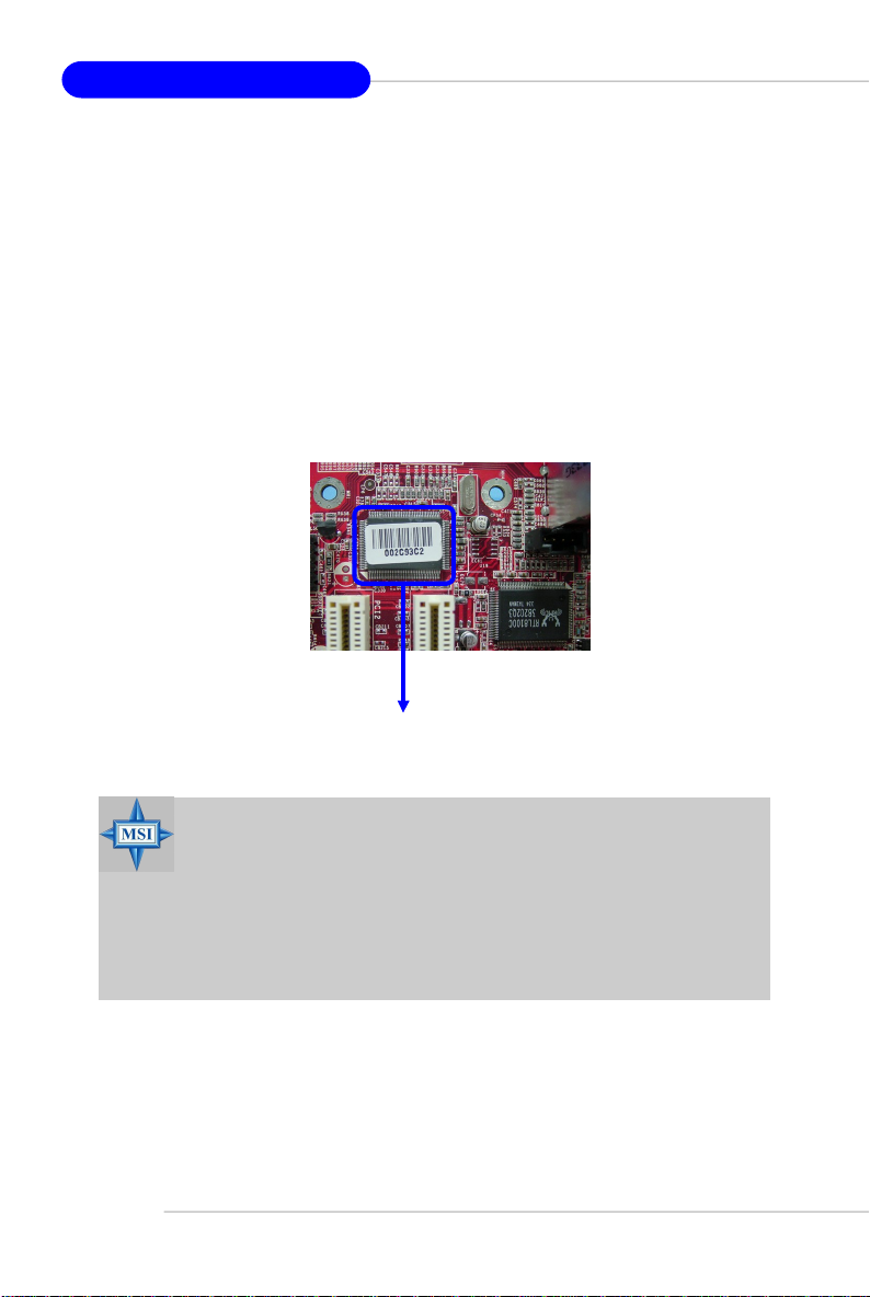
1394 GUID address
Label (optional)
MSI Reminds You...
1. Each board will be given a unique 1394 GUID from the
manufacturer’s default settings in the system BIOS.
2. Use the flash utility or Live Update from MSI’s website for BIOS
update. The 1394 GUID address is burnt in the BIOS core. If the 1394
GUID address is lost due to an unpredictable event, such as replacing a new BIOS chip, users can use the utility from MSI’s website by
entering the 1394 GUID address to recover its original one.
Page 15
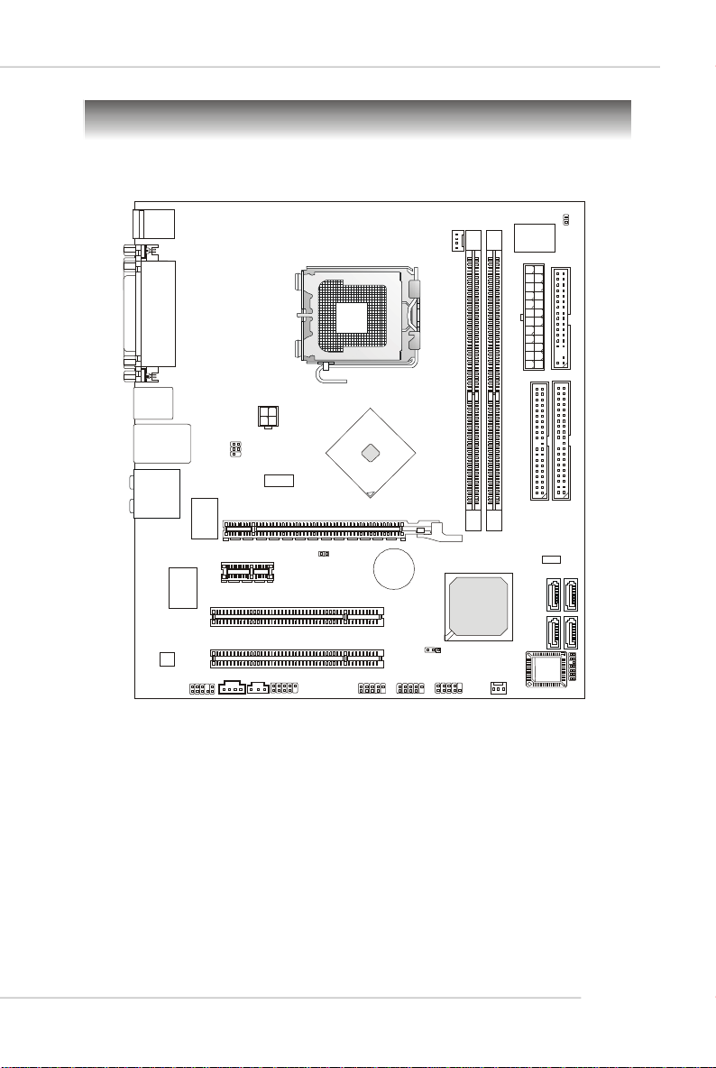
Mainboard Layout
PCIE 1X1
CPU_FAN1
PCIE16X1
BATT
JUSB1
JUSB2
CPU_FAN2
IDE 1
JCMOS1
FDD 1
BIOS
ATI RC410/RC410L
Getting Started
Top: Mouse
Bottom: Keyboard
Top:
Parallel Port
Bottom:
COM 1
VGA Port
Top: 1394 Port
USB PBottom:orts
Top: LAN Jack
Bottom: USB ports
T: C
S-Out
M: RS
-Out
B:
Side Surround
T:
Line-In
M:
Line-Out
B:
Mic
VIA
VT6307
ALC880
JAUD1
JPWD1
DIMM1
DIMM2
ATX1
JPW1
JTV1
IDE 2
RT L 811 0SB
JCD1
PCI1
PCI 2
SPDOUT
JPWD2
J1394_1
+
ATI SB450
JFP1
SATA2
SATA3 SATA1
SATA4
JLPC1
RC410M Series (MS-7173 v1.X) M-ATX Mainboard
1-5
Page 16
MS-7173 M-ATX Mainboard
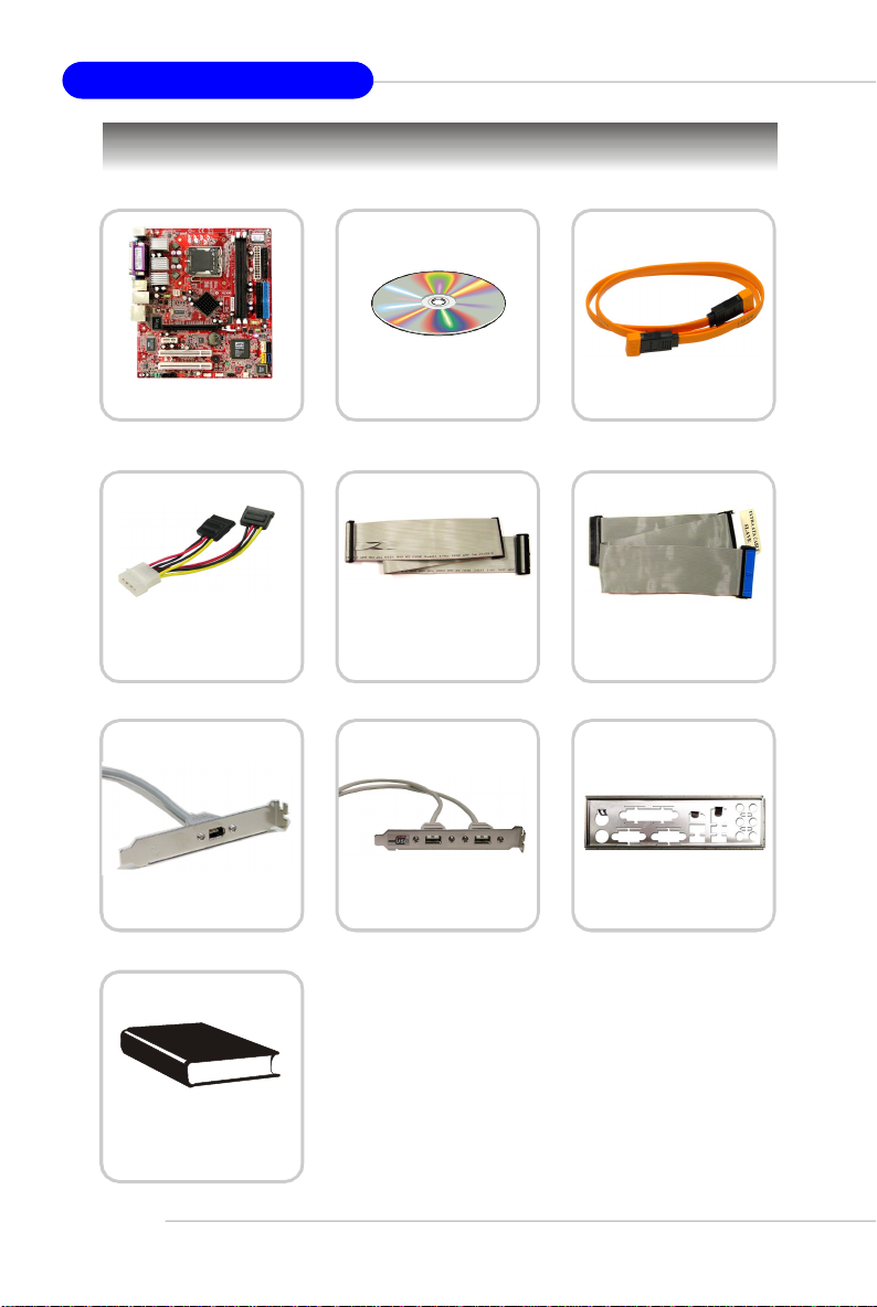
Packing Checklist
MSI motherboard
Power Cable
1394 Bracket (Optional) USB Bracket (Optional)
MSI Driver/Utility CD
Standard Cable for
Floppy Disk
* The pictures are for reference only. Your packing
contents may vary depending on the model you
purchased.
SATA Cable (Optional)
Standard Cable for
IDE Devices
Back IO Shield
1-6
User’ s Guide
Page 17

Hardware Setup
Chapter 2. Hardware
Setup
Hardware Setup
This chapter provides you with the information about hardware setup
procedures. While doing the installation, be careful in holding the
components and follow the installation procedures. For some
components, if you install in the wrong orientation, the components
will not work properly.
Use a grounded wrist strap before handling computer components.
Static electricity may damage the components.
2-1
Page 18
MS-7173 M-ATX Mainboard
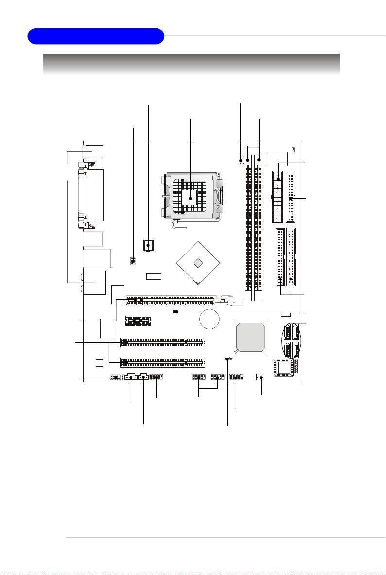
Quick Components Guide
Back Panel
I/O, p.2-10
PCI Express
Slots, p.2-21
PCI Slots,
p.2-21
JAUD1, p.2-15
JPW1, p.2-9
JTV1, p.2-18
CPU, p.2-3
CPU_FAN1, p.2-12
DDR DIMMs, p.2-7
ATX1, p.2-9
FDD1, p.2-12
IDE1/2, p.2-13
JPWD1,p.2-20
SATA1~4,
p.2-14
2-2
JCD1, p.2-15
SPDOUT, p.2-19
J1394_1,
p.2-16
JUSB1,
JUSB2,
p.2-17
JFP1, p.2-17
JCMOS1,
p.2-20
CPU_FAN2, p.2-12
Page 19
Hardware Setup
Central Processing Unit: CPU
This mainboard supports Intel® Pentium 4 Cedar Mill processor in LGA 775 package.
When you are installing the CPU, make sure to install the cooler to prevent
overheating. If you do not have the CPU cooler, contact your dealer to purchase
and install them before turning on the computer.
For the latest information about CPU, please visit http://www.msi.com.tw/program/
products/mainboard/mbd/pro_mbd_cpu_support.php.
MSI Reminds You...
Overheating
Overheating will seriously damage the CPU and system, always make
sure the cooling fan can work properly to protect the CPU from
overheating.
Replacing the CPU
While replacing the CPU, always turn off the ATX power supply or
unplug the power supply’s power cord from grounded outlet first to
ensure the safety of CPU.
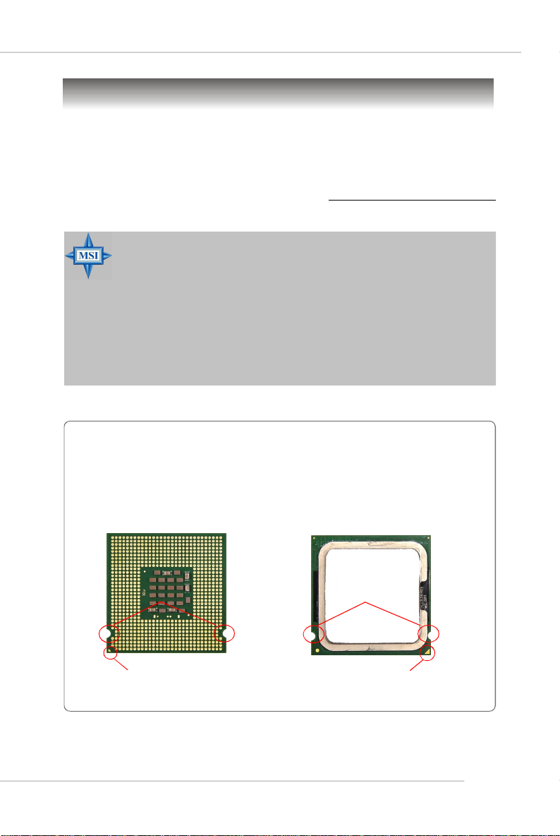
Introduction to LGA 775 CPU
The pin-pad side of LGA 775
CPU.
Alignment Key Alignment Key
Yellow triangle is the Pin 1 indicator
The surface of LGA 775 CPU.
Remember to apply some silicone heat transfer compound on
it for better heat dispersion.
Yellow triangle is the Pin 1 indicator
2-3
Page 20
MS-7173 M-ATX Mainboard
CPU & Cooler Installation
When you are installing the CPU, make sure the CPU has a cooler attached on
the top to prevent overheating. If you do not have the cooler, contact your dealer
to purchase and install them before turning on the computer. Meanwhile, do not
forget to apply some silicon heat transfer compound on CPU before installing the heat
sink/cooler fan for better heat dispersion.
Follow the steps below to install the CPU & cooler correctly. Wrong installation will
cause the damage of your CPU & mainboard.
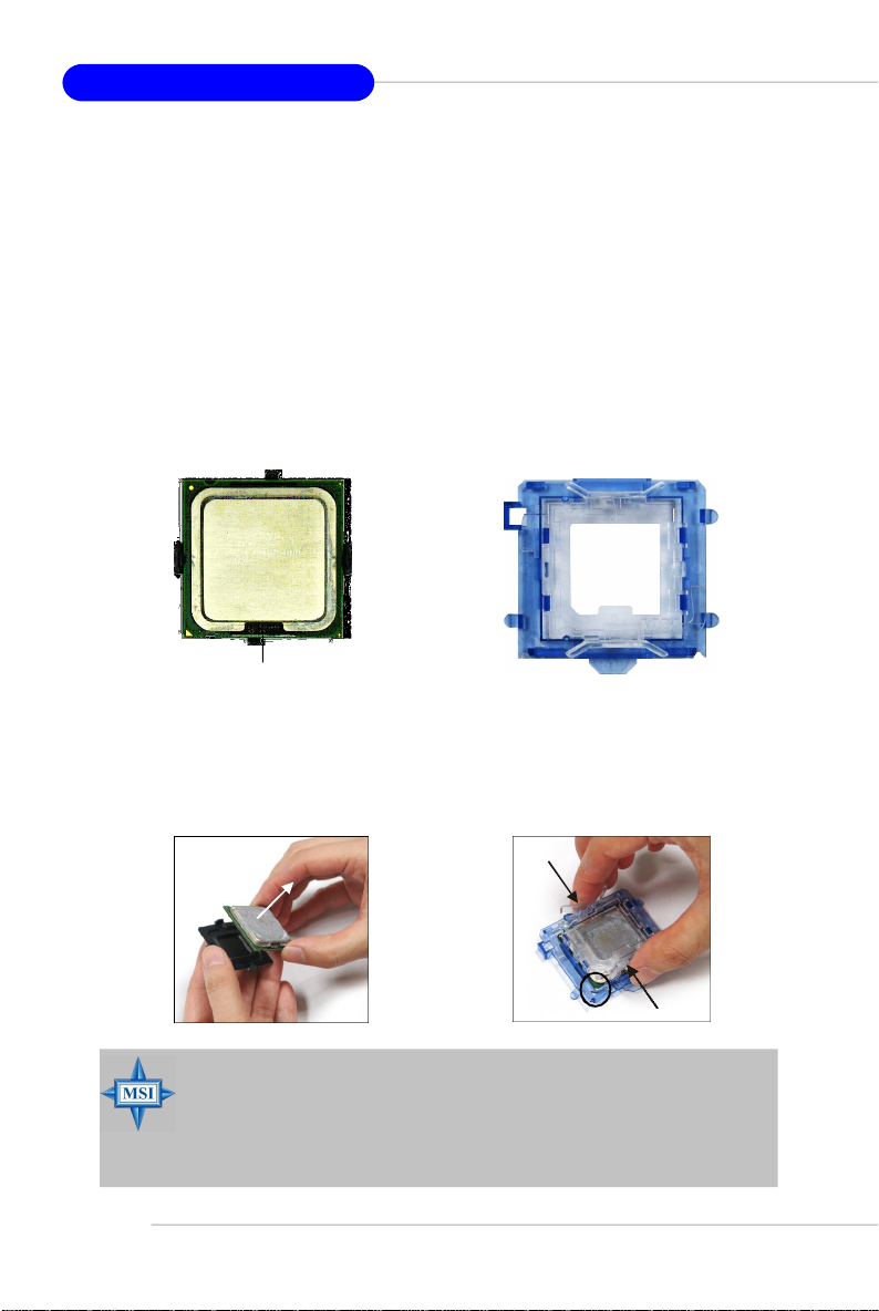
1.The CPU has a land side cover on the
bottom to protect the CPU contact from
damage. Rotate it to make the pin 1
indicator (yellow triangle) in the rightbottom corner.
land side cover
3.Use 2 hands to remove the land side
cover (if any). Please note not to touch
the pins.
2.Take out the accompanying CPU Clip
and rotate it for the same direction
as the CPU (Pin 1 indicator is in the
left-bottom corner).
4.Align the two pin 1 indicators (the
triangles on the CPU & the CPU Clip),
and use the CPU Clip to clip the CPU
up, pressing the clips on both sides
to the center, as the arrows shown.
2-4
MSI Reminds You...
1.Confirm if your CPU cooler is firmly installed before turning on your
system.
2.Do not touch the CPU socket pins to avoid damaging.
3. The availability of the CPU land side cover depends on your CPU
packing.
Page 21
Hardware Setup
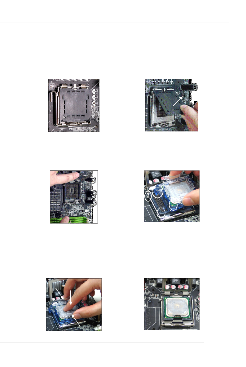
5.The CPU has a plastic cap on it to
protect the contact from damage.
Before you have installed the CPU,
always cover it to protect the socket
pin.
7.Lift the load lever up and open the
load plate.
6.Remove the cap from lever hinge side
(as the arrow shows). The pins of
socket reveal.
8.Correctly align the triangle of CPU Clip
with the CPU chamfer, and the square
on the CPU Clip to the hook of the
socket.
9.Use your thumb and the middle fingers to push the clips to release the
CPU, then press down the CPU with
your index finger to allow the whole
module to be installed onto the CPU
socket.
10.The CPU is installed well on the CPU
socket.
2-5
Page 22
MS-7173 M-ATX Mainboard
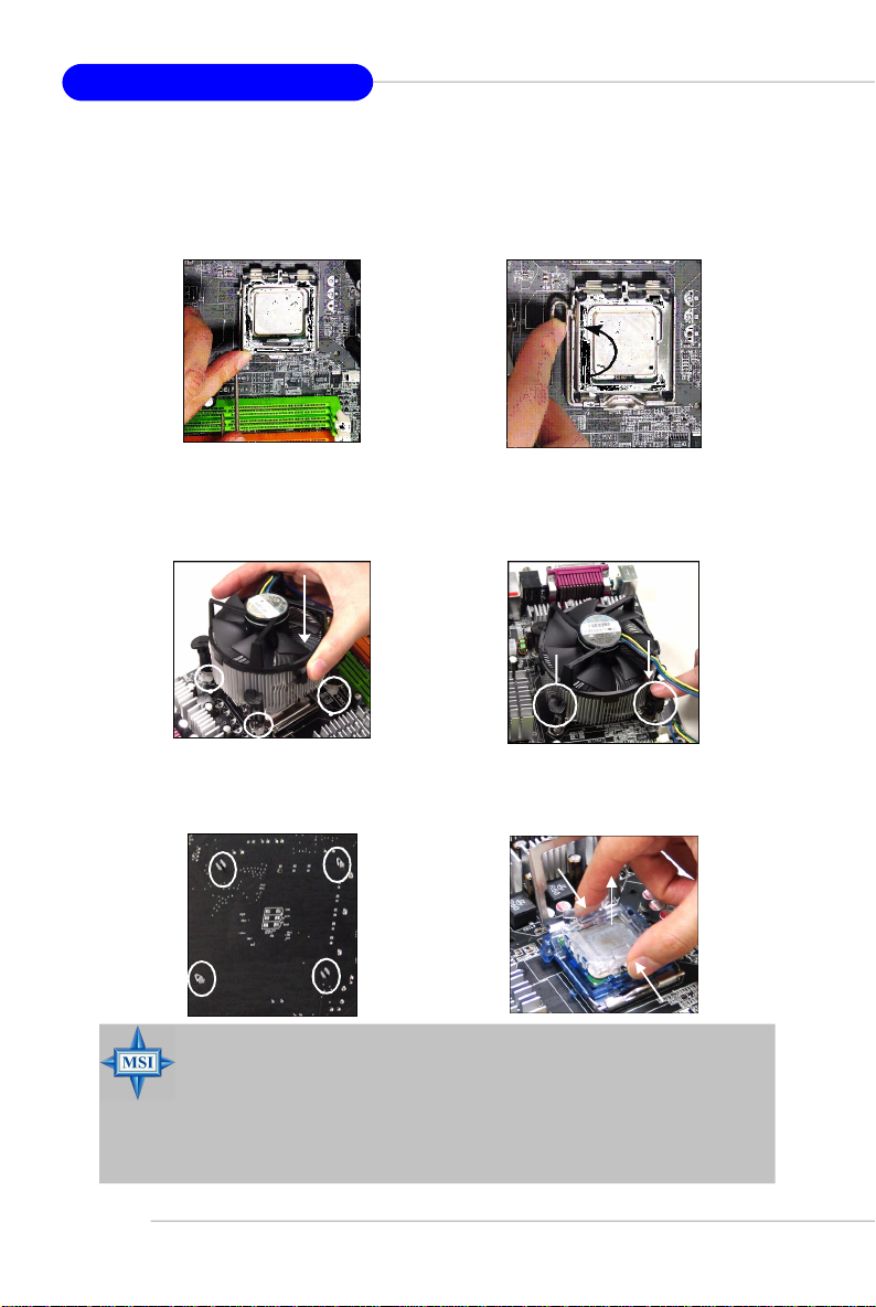
11.Visually inspect if the CPU is seated
well into the socket, then remove the
CPU Clip with 2 fingers. Then cover
the load plate onto the package.
13. Align the holes on the mainboard with
the cooler. Push down the cooler until
its four clips get wedged into the
holes of the mainboard.
15.Turn over the mainboard to confirm
that the clip-ends are correctly
inserted.
12. Press down the load lever lightly
onto the load plate, and then secure
the lever with the hook under retention tab.
14.Press the four hooks down to fasten
the cooler. Then rotate the locking
switch (refer to the correct direction
marked on it) to lock the hooks.
locking
switch
Note:If you want to uninstall the CPU,
align the 4 points (see Point 8 for
details) again and push the clip to
lift up the CPU.
2-6
MSI Reminds You...
1.Check the information in PC Health Status of H/W Monitor in BIOS
(Chapter 3) for the CPU temperature.
2. Whenever CPU is not installed, always protect your CPU socket pin
with the plastic cap covered (shown in Figure 1) to avoid damaging.
3. Please note that the mating/unmating durability of the CPU is 20 cycles.
Therefore we suggest you do not plug/unplug the CPU too often.
Page 23
Hardware Setup
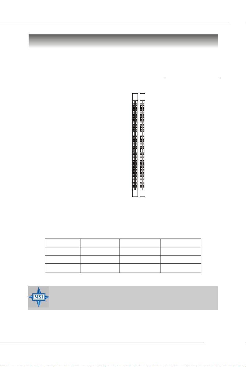
Memory
The mainboard provides two 240-pin non-ECC DDR II 667 DIMMs and supports up to
2GB system memory.
For more information on compatible components, please visit http://www.msi.com.tw/
program/products/mainboard/mbd/pro_mbd_trp_list.php.
DIMM1~DIMM2
(from left to right)
Memory Population Rules
This mainboard supports DDR II 667 memory interface.
Each DIMM slot supports up to a maximum size of 2GB. Users can install either single-
or double-sided modules depending on their needs.
Slot Combination 1 Combination 2 Combination 3
DIMM1 64MB~1GB 2GB 0
DIMM2 64MB~1GB 0 2GB
Total Memory 128MB~2GB 2GB 2GB
MSI Reminds You...
Make sure that you install memory modules of the same type and
density on DDR II DIMMs.
2-7
Page 24
MS-7173 M-ATX Mainboard
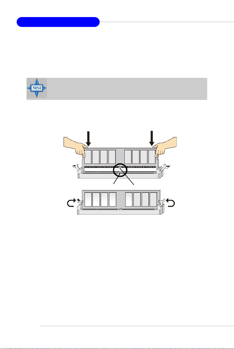
Installing DDR II Modules
1. The DDR II DIMM has only one notch on the center of module. The module will only
fit in the right orientation.
2. Insert the DIMM memory module vertically into the DIMM slot. Then push it in until the
golden finger on the memory module is deeply inserted in the socket.
MSI Reminds You...
You can barely see the golden finger if the module is properly inserted
in the socket.
3. The plastic clip at each side of the DIMM slot will automatically close.
2-8
Volt
Notch
Page 25
Hardware Setup
Power Supply
The mainboard supports ATX power supply for the power system. Before inserting
the power supply connector, always make sure that all components are installed
properly to ensure that no damage will be caused.
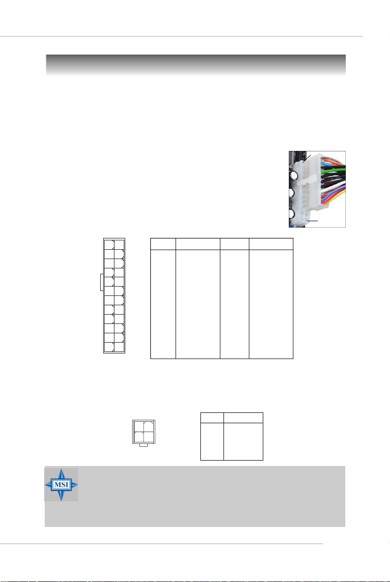
ATX 24-Pin Power Connector: ATX1
This connector allows you to connect an ATX 24-pin power supply. To connect the
ATX 24-pin power supply, make sure the plug of the power supply
is inserted in the proper orientation and the pins are aligned. Then
push down the power supply firmly into the connector.
You may use the 20-pin ATX power supply as you like. If you’d like
to use the 20-pin ATX power supply, please plug your power supply along with pin 1 & pin 13 (refer to the image at the right hand).
There is also a foolproof design on pin 11, 12, 23 & 24 to avoid
wrong installation.
Pin Definition
13
ATX1
24
1
PIN SIGNAL
1 +3.3V
2 +3.3V
3 GND
4 +5V
5 GND
6 +5V
7 GND
8 PWR OK
9 5VSB
10 +12V
11 +12V
12
12 NC
PIN SIGNAL
13 +3.3V
14 -12V
15 GND
16 PS-ON#
17 GND
18 GND
19 GND
20 Res
21 +5V
22 +5V
23 +5V
24 GND
pin 13
pin 12
ATX 12V Power Connector: JPW1
This 12V power connector is used to provide power to the CPU.
JPW1
1
2
34
MSI Reminds You...
1. These two connectors connect to the ATX power supply and have to
work together to ensure stable operation of the mainboard.
2. Power supply of 350 watts (and above) is highly recommended for
system stability.
3. ATX 12V power connection should be greater than 18A.
JPW1 Pin Definition
PIN SIGNAL
1 GND
2 GND
3 12V
4 12V
2-9
Page 26
MS-7173 M-ATX Mainboard
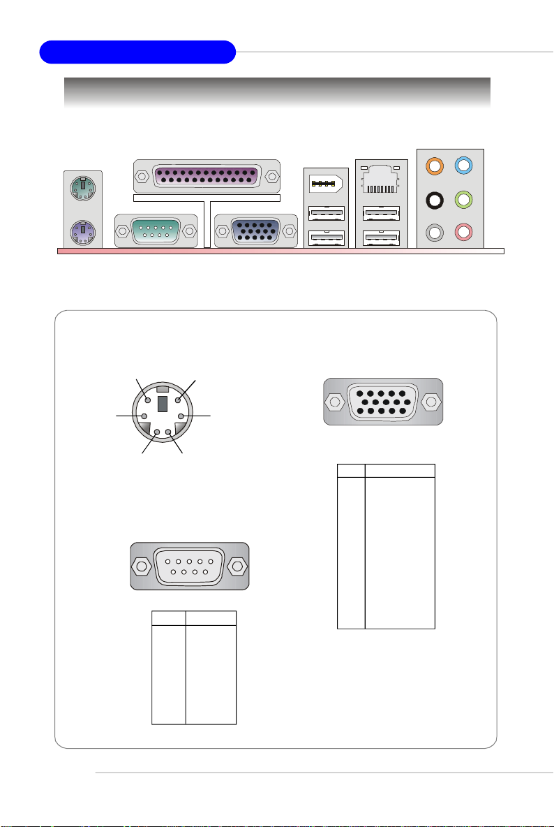
Back Panel
Mouse
Keyboard USB Ports
Parallel
VGA PortSerial Port
Mouse/Keyboard Connector
Pin5
Pin6 NC
Pin2 NC
Mouse/KBD Clock
Pin3 GNDPin4 VCC
Pin1
Mouse/KBD
DATA
Serial Port
1 2 3 4 5
6 7 8 9
PIN SIGNAL
1 DCD
2 SIN
3 SOUT
4 DTR
5 GND
6 DSR
7 RTS
8 CTS
9 RI
1394 Port
(Optional)
VGA Port
LAN
5
15
PIN SIGNAL
1 RED
2 GREEN
3 BLUE
4 N/C
5 GND
6 GND
7 GND
8 GND
9 +5V
10 GND
11 N/C
12 SDA
13 Horizontal Sync
14 Vertical Sync
15 SCL
CS-Out
RS-Out
Side
Surround
1
11
L-In
L-Out
Mic
2-10
Page 27
Hardware Setup
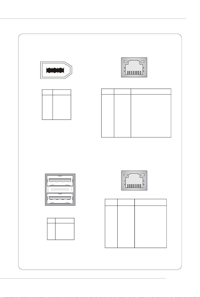
IEEE 1394 Port (Optional)
6
12345
PIN SIGNAL
1 PWR
2 GND
3 TPB4 TPB+
5 TPA6 TPA+
USB Ports
1 2 3 4
10/100 LAN Jack (Optional)
8 1
10/100 LAN
PIN SIGNAL DESCRIPTION
1 TDP Transmit Differential Pair
2 TDN Transmit Differential Pair
3 RDP Receive Differential Pair
4 NC Not Used
5 NC Not Used
6 RDN Receive Differential Pair
7 NC Not Used
8 NC Not Used
Gigabit LAN Jack (Optional)
8 1
PIN SIGNAL
1 VCC
2 -Data
3 +Data
4 GND
PIN SIGNAL DESCRIPTION
1 D0P Differential Pair 0+
2 D0N Differential Pair 03 D1P Differential Pair 1+
4 D2P Differential Pair 2+
5 D2N Differential Pair 26 D1N Differential Pair 17 D3P Differential Pair 3+
8 D3N Differential Pair 3-
2-11
Page 28
MS-7173 M-ATX Mainboard
Connectors
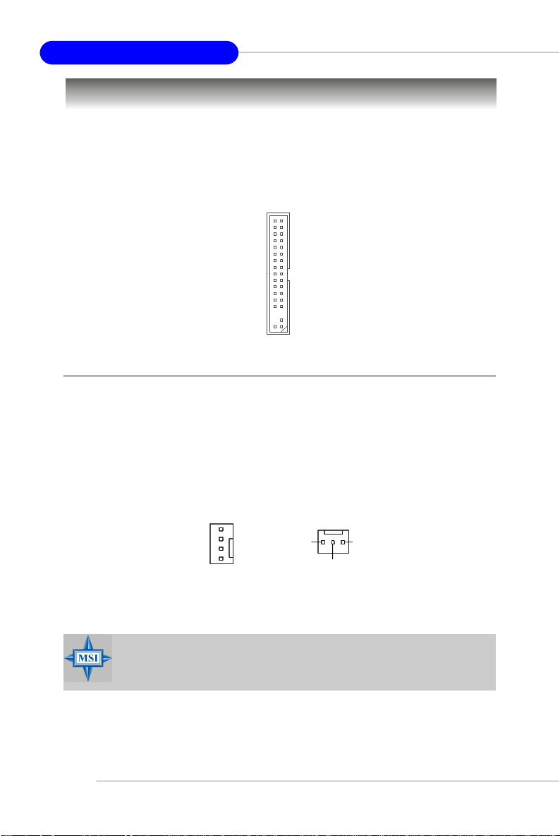
Floppy Disk Drive Connector: FDD1
The mainboard provides a standard floppy disk drive connector that supports 360K,
720K, 1.2M, 1.44M and 2.88M floppy disk types.
FDD1
Fan Power Connectors: CPU_FAN1 / CPU_FAN2
The fan power connectors support system cooling fan with +12V. When connecting
the wire to the connectors, always take note that the red wire is the positive and
should be connected to the +12V, the black wire is Ground and should be connected
to GND. If the mainboard has a System Hardware Monitor chipset on-board, you must
use a specially designed fan with speed sensor to take advantage of the CPU fan
control.
2-12
CONTROL
SENSOR
+12V
GND
CPU_FAN1
SENSOR
CPU_FAN2
GND
+12V
MSI Reminds You...
Please refer to the recommended CPU fans at Intel® official website
or consult the vendors for proper CPU cooling fan.
Page 29
Hardware Setup
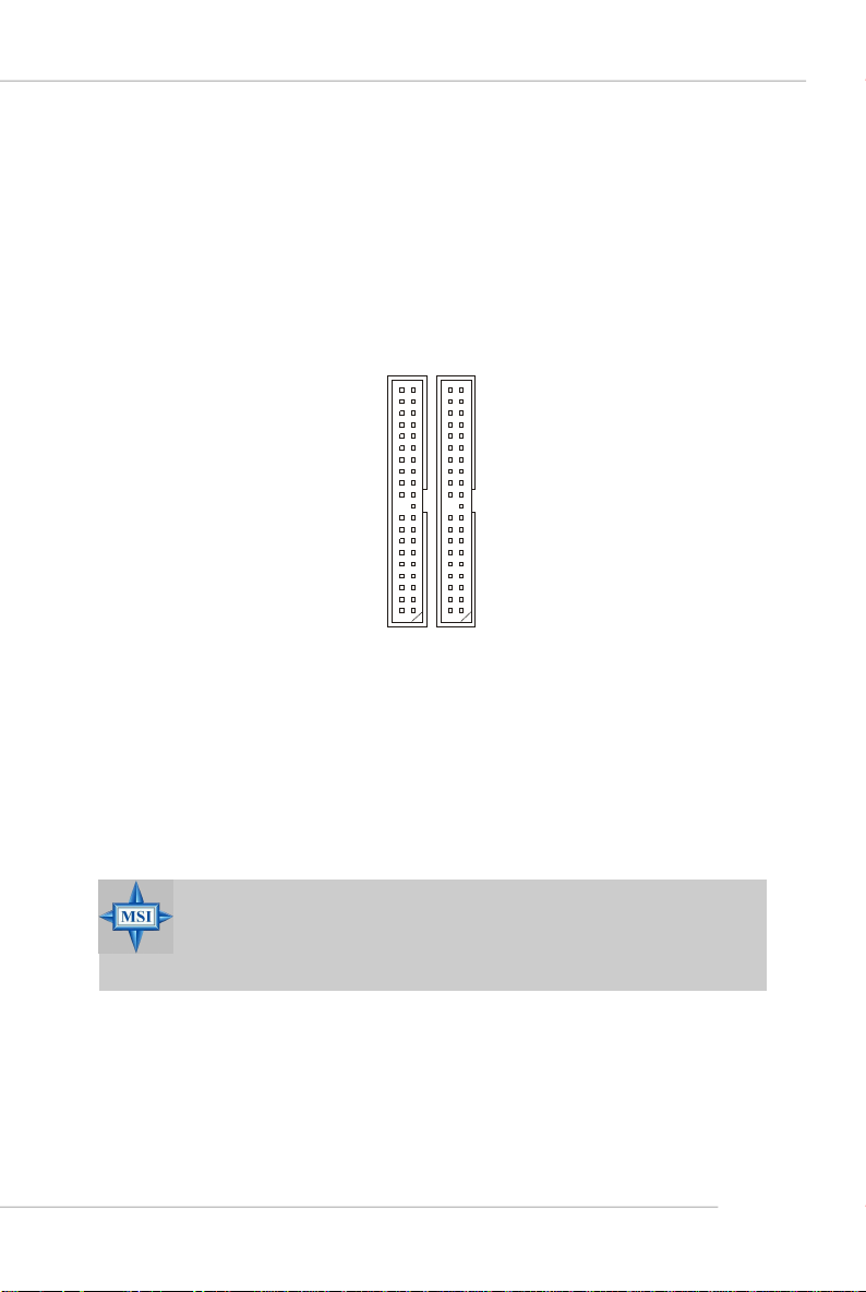
ATA133 Hard Disk Connectors: IDE1 & IDE2
The mainboard has a 32-bit Enhanced PCI IDE and Ultra DMA 66/100/133 controller
that provides PIO mode 0~4, Bus Master, and Ultra DMA 66/100/133 function. You can
connect up to four hard disk drives, CD-ROM and other IDE devices.
The Ultra ATA133 interface boosts data transfer rates between the computer and the
hard drive up to 133 megabytes (MB) per second. The new interface is one-third
faster than earlier record-breaking Ultra ATA/100 technology and is backwards
compatible with the existing Ultra ATA interface.
IDE2IDE1
IDE1 (Primary IDE Connector)
The first hard drive should always be connected to IDE1. IDE1 can connect a Master
and a Slave drive. You must configure second hard drive to Slave mode by setting the
jumper accordingly.
IDE2 (Secondary IDE Connector)
IDE2 can also connect a Master and a Slave drive.
MSI Reminds You...
If you install two hard disks on cable, you must configure the second
drive to Slave mode by setting its jumper. Refer to the hard disk documentation supplied by hard disk vendors for jumper setting instructions.
2-13
Page 30
MS-7173 M-ATX Mainboard
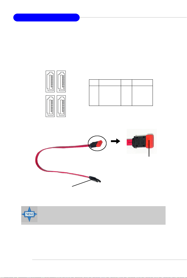
Serial ATA Connectors: SATA1~SATA4
The ATI SB450 SouthBridge supports four serial ATA connectors SATA1~SATA4.
SATA1~SATA4 are high-speed Serial ATA interface ports. Each supports 1st generation serial ATA data rates of 150MB/s and is fully compliant with Serial ATA 1.0
specifications. Each Serial ATA connector can connect to 1 hard disk device.
SATA1SATA2
7
1
7
1
SATA1~ SATA4 Pin Definition
PIN SIGNAL PIN SIGNAL
1 GND 2 TXP
3 TXN 4 GND
5 RXN 6 RXP
7 GND
SATA3SATA4
Serial ATA cable
Take out the dust cover and
connect to the hard disk
devices
Connect to SATA1/2/3/4
MSI Reminds You...
Please do not fold the Serial ATA cable into 90-degree angle. Otherwise,
data loss may occur during transmission.
2-14
Page 31

Hardware Setup
CD-In Connector: JCD1
This connector is provided for CD-ROM audio.
CD1
R
L
GND
Front Panel Audio Connector: JAUD1
The JAUD1 front panel audio connector allows you to connect to the front panel
audio and is compliant with Intel® Front Panel I/O Connectivity Design Guide.
JAUD1
2
1
10
9
Pin Definition
PIN SIGNAL DESCRIPTION
1 AUD_MIC Front panel microphone input signal
2 AUD_GND Ground used by analog audio circuits
3 AUD_MIC_BIAS Microphone power
4 AUD_VCC Filtered +5V used by analog audio circuits
5 AUD_FPOUT_R Right channel audio signal to front panel
6 AUD_RET_R Right channel audio signal return from front panel
7 HP_ON Reserved for future use to control headphone amplifier
8 KEY No pin
9 AUD_FPOUT_L Left channel audio signal to front panel
10 AUD_RET_L Left channel audio signal return from front panel
MSI Reminds You...
If you don’t want to connect to the front audio header,
pins 5 & 6, 9 & 10 have to be jumpered in order to have
signal output directed to the rear audio ports. Otherwise,
the Line-Out connector on the back panel will not
function.
6
10
5
9
2-15
Page 32

MS-7173 M-ATX Mainboard
IEEE 1394 Connectors: J1394_1 (Optional)
The mainboard provides one 1394 pin header that allows you to connect IEEE 1394
ports via an external IEEE1394 bracket (optional).
PIN SIGNAL PIN SIGNAL
1 TPA+ 2 TPA3 Ground 4 Ground
5 TPB+ 6 TPB7 Cable power 8 Cable power
9 Key (no pin) 10 Ground
Connected to J1394_1
2
1
J1394_1
Pin Definition
9
10
2-16
IEEE1394 Bracket (Optional)
Foolproof
design
Page 33

Hardware Setup
Front Panel Connectors: JFP1
The mainboard provides one front panel connector for electrical connection to the
front panel switches and LEDs. The JFP1 is compliant with Intel® Front Panel I/O
Connectivity Design Guide.
JFP1 Pin Definition
PIN SIGNAL DESCRIPTION
1 HD_LED_P Hard disk LED pull-up
2 FP PWR/SLP MSG LED pull-up
3 HD_LED_N Hard disk active LED
10
9
4 FP PWR/SLP MSG LED pull-up
5 RST_SW_N Reset Switch low reference pull-down to GND
6 PWR_SW_P Power Switch high reference pull-up
7 RST_SW_P Reset Switch high reference pull-up
8 PWR_SW_N Power Switch low reference pull-down to GND
9 RSVD_DNU Reserved. Do not use.
JFP1
Power
LED
2
1
HDD
LED
Power
Switch
Reset
Switch
Front USB Connectors: JUSB1 / JUSB2
The mainboard provides two standard USB 2.0 pin headers JUSB1 & JUSB2 . USB 2.
0 technology increases data transfer rate up to a maximum throughput of 480Mbps,
which is 40 times faster than USB 1.1, and is ideal for connecting high-speed USB
interface peripherals such as USB HDD, digital cameras, MP3 players, printers,
modems and the like.
2 10
1
JUSB1, JUSB2
(USB 2.0)
9
JUSB1 & JUSB2 Pin Definition
PIN SIGNAL PIN SIGNAL
1 VCC 2 VCC
3 USB0- 4 USB15 USB0+ 6 USB1+
7 GND 8 GND
9 Key (no pin) 10 USBOC
Connected to JUSB1 or JUSB2
MSI Reminds You...
Note that the pins of VCC and GND must be connected correctly to
avoid possible damage.
USB 2.0 Bracket
(Optional)
2-17
Page 34

MS-7173 M-ATX Mainboard
TV-Out Connector: JTV1 (Optional)
The mainboard optionally provides a TV-Out connector for you to attach a TV-Out
bracket. The TV-Out bracket offers two types of TV-Out connectors: S-Video and
RCA Composite connector. Select the appropriate one to connect to the television
and the television will be able to display PC’s information.
JTV1 Pin Definition
4
1
2
3
TV-Out Bracket
(Optional)
5
JTV1
Pin Description Pin Description
1 GND 4 COMP
2 Y 5 GND
3 C
2-18
TV-Out Connector
(S-Video)
TV-Out Connector
(RCA Composite)
Page 35

Hardware Setup
SPDIF-Out Connector: SPDOUT (Optional)
This connector is used to connect SPDIF (Sony & Philips Digital Interconnect Format)
interface for digital audio transmission.
SPDOUT
Connect to SPDOUT
VCC
GND
SPDIF
SPDIF Bracket (Optional)
2-19
Page 36

MS-7173 M-ATX Mainboard
Jumpers
The motherboard provides the following jumpers for you to set the computer’s function.
This section will explain how to change your motherboard’s function through the use
of jumpers.
Clear BIOS Password Jumper: JPWD1
The jumper is used to clear the BIOS password. To clear the password, open the
jumper and restart your computer.
JPWD1
NormalClear
Clear CMOS Jumper: JCMOS1
There is a CMOS RAM onboard that has a power supply from external battery to keep
the data of system configuration. With the CMOS RAM, the system can automatically
boot OS every time it is turned on. If you want to clear the system configuration, set
the JCMOS1 (Clear CMOS Jumper ) to clear data.
2-20
JCMOS1
3
1
Keep Data Clear Data
3
1
1
MSI Reminds You...
To clear CMOS you should:
1. switch off the system and short 2-3 pin of the JCMOS1;
2. switch on the system again and the message “CMOS checksum
error” should appear;
3. switch off the system and return to 1-2 pin (Keep Data) position;
4. switch on again for operation.
Please avoid clearing CMOS while the system is on; it will damage
the mainboard.
Page 37

Hardware Setup
Slots
The motherboard provides one PCI Express x1 slot, one PCI Express x16 slot, and
two 32-bit/33MHz PCI slots.
PCI (Peripheral Component Interconnect) Express Slots
The PCI Express slots support high-bandwidth, low pin count, and serial interconnect
technology. You can insert the expansion cards to meet your needs. When adding or
removing expansion cards, make sure that you unplug the power supply first.
PCI Express architecture provides a high performance I/O infrastructure for Desktop
Platforms with transfer rates starting at 2.5 Giga transfers per second over a PCI
Express x1 lane for Gigabit Ethernet, TV Tuners, 1394 controllers, and general purpose I/O. Also, desktop platforms with PCI Express Architecture will be designed to
deliver highest performance in video, graphics, multimedia and other sophisticated
applications. Moreover, PCI Express architecture provides a high performance graphics
infrastructure for Desktop Platforms doubling the capability of existing AGP 8x designs with transfer rates of 4.0 GB/s over a PCI Express x16 lane for graphics
controllers, while PCI Express x1 supports transfer rate of 250 MB/s.
PCI Express x16 slot
PCI Express x1 slot
PCI (Peripheral Component Interconnect) Slots
The PCI slots allow you to insert the expansion cards to meet your needs. When
adding or removing expansion cards, make sure that you unplug the power supply
first. Meanwhile, read the documentation for the expansion card to make any necessary hardware or software settings for the expansion card, such as jumpers,
switches or BIOS configuration.
PCI Slot
PCI Interrupt Request Routing
The IRQ, acronym of interrupt request line and pronounced I-R-Q, are hardware lines
over which devices can send interrupt signals to the microprocessor. The PCI IRQ
pins are typically connected to the PCI bus pins as follows:
Order 1 Order 2 Order 3 Order 4
PCI Slot 1 INT E# INT F# INT G# INT H#
PCI Slot 2 INT F# INT G# INT H# INT E#
2-21
Page 38

BIOS Setup
Chapter 3. BIOS Setup
BIOS Setup
This chapter provides information on the BIOS Setup program and
allows you to configure the system for optimum use.
You may need to run the Setup program when:
² An error message appears on the screen during the system boot-
ing up, and requests you to run SETUP.
² You want to change the default settings for customized features.
MSI Reminds You...
1. The items under each BIOS category described in this chapter
are under continuous update for better system performance.
Therefore, the description may be slightly different from the latest BIOS and should be held for reference only.
2. Upon boot-up, the 1st line appearing after the memory count is
the BIOS version. It is usually in the format:
A7173MS V1.0 221105 where:
1st digit refers to BIOS maker as A = AMI, W = AWARD,
and P = PHOENIX.
2nd - 5th digit refers to the model number.
6th - 7th digit refers to the customer as MS = all standard
customers.
V1.0 refers to the BIOS version.
221105 refers to the date this BIOS was released.
3-1
Page 39

MS-7173 M-ATX Mainboard
Restore the previous CMOS value from CMOS, only for
Entering Setup
Power on the computer and the system will start POST (Power On Self Test) process.
When the message below appears on the screen, press <DEL> key to enter Setup.
Press DEL to enter SETUP
If the message disappears before you respond and you still wish to enter Setup,
restart the system by turning it OFF and On or pressing the RESET button. You may
also restart the system by simultaneously pressing <Ctrl>, <Alt>, and <Delete> keys.
Control Keys
3-2
<↑>
<↓>
<←>
<→>
<Enter> Select the item
<Esc> Jumps to the Exit menu or returns to the main menu
<+/PU> Increase the numeric value or make changes
<-/PD> Decrease the numeric value or make changes
<F1> General help, only for Status Page Setup Menu and
<F5>
<F7> Load Optimized defaults
<F10> Save all the CMOS changes and exit
Move to the previous item
Move to the next item
Move to the item in the left hand
Move to the item in the right hand
from a submenu
Option Page Setup Menu
Option Page Setup Menu
Page 40

BIOS Setup
Getting Help
After entering the Setup menu, the first menu you will see is the Main Menu.
Main Menu
The main menu lists the setup functions you can make changes to. You can use the
control keys ( ↑↓ ) to select the item. The on-line description of the highlighted setup
function is displayed at the bottom of the screen.
Sub-Menu
If you find a right pointer symbol (as shown in the right view) appears to the left of
certain fields that means a sub-menu containing additional options can be launched from this field. You can
use control keys ( ↑↓ ) to highlight the field and press
<Enter> to call up the sub-menu. Then you can use the
control keys to enter values and move from field to
field within a sub-menu. If you want to return to the
main menu, just press <Esc >.
General Help <F1>
The BIOS setup program provides a General Help screen. You can call up this screen
from any menu by simply pressing <F1>. The Help screen lists the appropriate keys
to use and the possible selections for the highlighted item. Press <Esc> to exit the
Help screen.
3-3
Page 41

MS-7173 M-ATX Mainboard
The Main Menu
Once you enter BIOS CMOS Setup Utility, the Main Menu (Figure 1) will appear on the
screen. The Main Menu allows you to select from twelve setup functions and two
exit choices. Use arrow keys to select among the items and press <Enter> to accept
or enter the sub-menu.
Standard CMOS Features
Use this menu for basic system configurations, such as time, date etc.
Advanced BIOS Features
Use this menu to setup the items of BIOS special enhanced features.
Advanced Chipset Features
Use this menu to change the values in the chipset registers and optimize your system’s
performance.
Integrated Peripherals
Use this menu to specify your settings for integrated peripherals.
Power Management Features
Use this menu to specify your settings for power management.
PNP/PCI Configurations
This entry appears if your system supports PnP/PCI.
3-4
Page 42

BIOS Setup
H/W Monitor
This entry shows your PC health status.
Load Optimized Defaults
Use this menu to load the default values set by the mainboard manufacturer specifically for optimal performance of the mainboard.
BIOS Setting Password
Use this menu to set the password for BIOS.
Save & Exit Setup
Save changes to CMOS and exit setup.
Exit Without Saving
Abandon all changes and exit setup.
3-5
Page 43

MS-7173 M-ATX Mainboard
Standard CMOS Features
The items in Standard CMOS Features Menu are divided into several categories.
Each category includes no, one or more than one setup items. Use the arrow keys to
highlight the item and then use the <PgUp> or <PgDn> keys to select the value you
want in each item.
Date
This allows you to set the system to the date that you want (usually the current date).
The format is <day><month> <date> <year>.
day Day of the week, from Sun to Sat, determined by
month The month from Jan. through Dec.
date The date from 1 to 31 can be keyed by numeric function keys.
year The year can be adjusted by users.
Time
This allows you to set the system time that you want (usually the current time). The
time format is <hour> <minute> <second>.
Primary IDE Master/Slave, Secondary IDE Master/Slave, Third/Fourth/Fifth/
Sixth IDE Master
Press PgUp/<+> or PgDn/<-> to select [Manual], [None] or [Auto] type. Note that the
specifications of your drive must match with the drive table. The hard disk will not
work properly if you enter improper information for this category. If your hard disk
BIOS. Read-only.
3-6
Page 44

BIOS Setup
drive type is not matched or listed, you can use [Manual] to define your own drive
type manually.
If you select [Manual], related information is asked to be entered to the following
items. Enter the information directly from the keyboard. This information should be
provided in the documentation from your hard disk vendor or the system manufacturer.
[Access Mode] The settings are [CHS], [LBA], [Large], [Auto].
[Capacity] The formatted size of the storage device.
[Cylinder] Number of cylinders.
[Head] Number of heads.
[Precomp] Write precompensation.
[Landing Zone] Cylinder location of the landing zone.
[Sector] Number of sectors.
Floppy A
This item allows you to set the type of floppy drives installed.
System Information
The items in this sub-menu show the CPU type, BIOS version and memory status of
your system (read only).
3-7
Page 45
MS-7173 M-ATX Mainboard
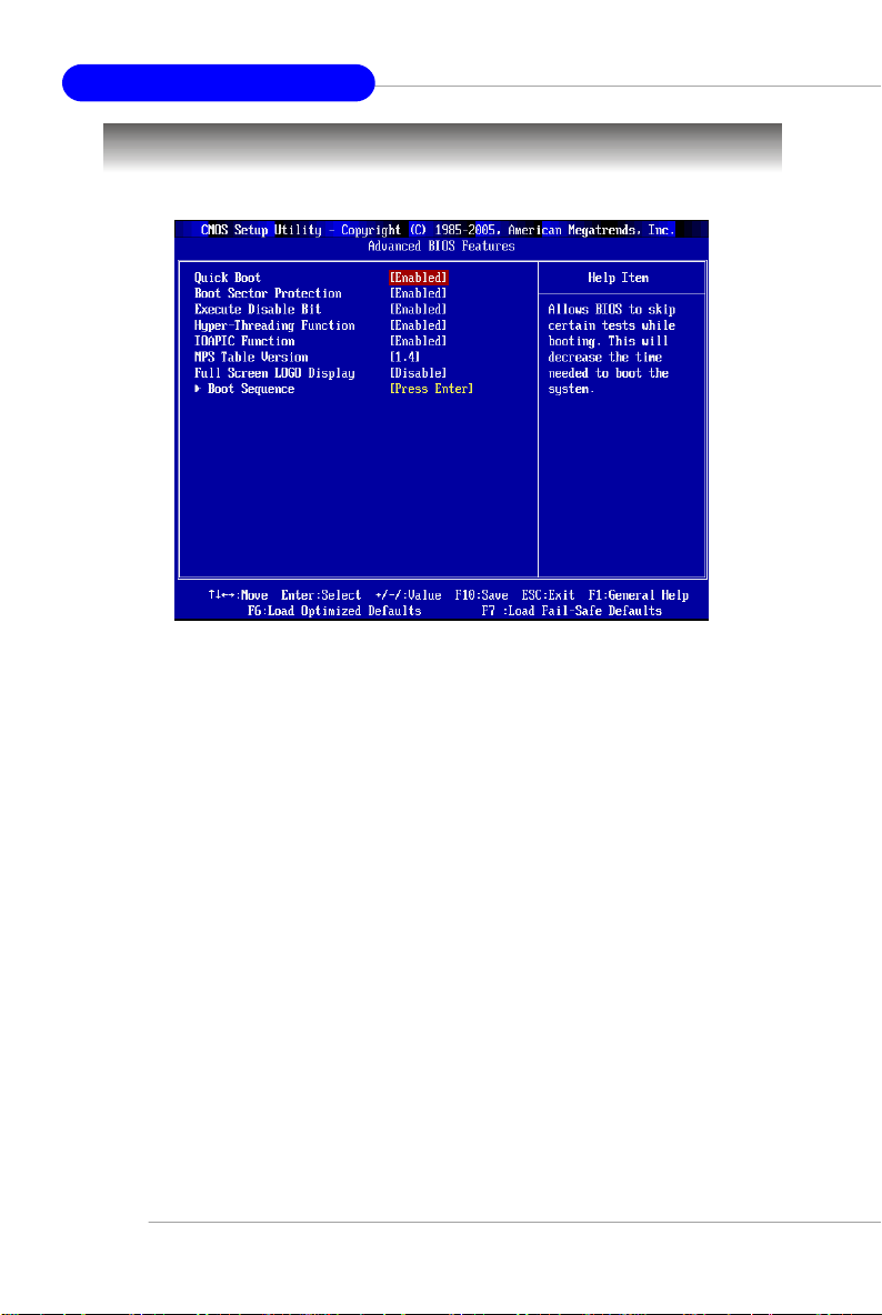
Advanced BIOS Features
Quick Boot
Setting the item to [Enabled] allows the system to boot within 5 seconds since it will
skip some check items. Available options: [Enabled], [Disabled].
Boot Sector Protection
This function protects the BIOS from accidental corruption by unauthorized users or
computer viruses. When enabled, the BIOS’ data cannot be changed when attempting to update the BIOS with a Flash utility. To successfully update the BIOS, you’ll
need to disable this Flash BIOS Protection function.
Execute Disable Bit
Intel's Execute Disable Bit functionality can prevent certain classes of malicious
"buffer overflow" attacks when combined with a supporting operating system. This
functionality allows the processor to classify areas in memory by where application
code can execute and where it cannot. When a malicious worm attempts to insert
code in the buffer, the processor disables code execution, preventing damage or
worm propagation.
Hyper-Threading Function
The processor uses Hyper-Threading technology to increase transaction rates and
reduces end-user response times. The technology treats the two cores inside the
processor as two logical processors that can execute instructions simultaneously.
In this way, the system performance is highly improved. If you disable the function,
3-8
Page 46

BIOS Setup
the processor will use only one core to execute the instructions. Please disable
this item if your operating system doesn’t support HT Function, or
unreliability and instability may occur.Settings: [Enabled], [Disabled].
MSI Reminds You...
Enabling the functionality of Hyper-Threading Technology for your
computer system requires ALL of the following platform Components:
* CPU: An Intel® Pentium® 4 Processor with HT Technology;
* Chipset: An Intel® Chipset that supports HT Technology;
* BIOS: A BIOS that supports HT Technology and has it
* OS: An operating system that supports HT Technology.
For more information on Hyper-threading Technology, go to:
www.intel.com/info/hyperthreading
IOAPIC Function
This field is used to enable or disable the APIC (Advanced Programmable Interrupt
Controller). Due to compliance with PC2001 design guide, the system is able to run in
APIC mode. Enabling APIC mode will expand available IRQ resources for the system.
Settings: [Enabled], [Disabled].
MPS Table Version
This field allows you to select which MPS (Multi-Processor Specification) version to
be used for the operating system. You need to select the MPS version supported by
your operating system. To find out which version to use, consult the vendor of your
operating system. Settings: [1.4], [1.1].
enabled;
Full Screen LOGO Display
This item enables you to show the company logo on the bootup screen. Settings are:
[Enabled] Shows a still image (logo) on the full screen at boot.
[Disabled] Shows the POST messages at boot.
Boot Sequence
Press <Enter> to enter the sub-menu and the following screen appears:
3-9
Page 47

MS-7173 M-ATX Mainboard
1st/2nd/3rd Boot Device
The items allow you to set the sequence of boot devices where BIOS attempts
to load the disk operating system.
Boot From Other Device
Setting the option to [Enabled] allows the system to try to boot from other device
if the system fails to boot from the 1st/2nd/3rd boot device.
Hard Disk Drives, Removable Drives, CD/DVD Drives
Press <Enter> to enter the sub-menu. Then you may use the arrow keys ( ↑↓ )
to select the desired device, then press <+>, <-> or <PageUp>, <PageDown>
key to move it up/down in this priority list.
3-10
Page 48

BIOS Setup
Advanced Chipset Features
MSI Reminds You...
Change these settings only if you are familiar with the chipset.
DRAM Timing
This field has the capacity to automatically detect all of the DRAM timing. If you set this
field to [Manual], the following fields will be selectable. The settings are: [Auto],
[Manual].
UMA Frame Buffer Size
Frame Buffer is the video memory that stores data for video display (frame). This field
is used to determine the memory size for Frame Buffer. Larger frame buffer size
increases video performance.
Surround View Function
SURROUNDVIEW™ provides the power and convenience of multi-adapter, multimonitor support for computers that use an AGP- or PCI Express®-based graphics
card in conjunction with ATI integrated graphics processors (IGPs). Setting options:
[Enabled], [Disabled].
A-Link & GPP Configuration
This setting controls the A-Link & GPP configuration.
3-11
Page 49

MS-7173 M-ATX Mainboard
Integrated Peripherals
USB Controller
This setting disables/enables the onchip USB controller. Setting options: [Enabled],
[Disabled].
USB Device Legacy Support
Set to [Enabled] if your need to use any USB 1.1/2.0 device in the operating system
that does not support or have any USB 1.1/2.0 driver installed, such as DOS and SCO
Unix. Set to [Disabled] only if you want to use any USB device other than the USB
mouse. Setting options: [Disabled], [Enabled].
Onboard LAN Controller
This setting allows you to enable/disable the onboard LAN controller. Setting options:
[Enabled], [Disabled].
Onboard LAN Option ROM
This setting enables/disables the initialization of the onboard LAN Boot ROM during
bootup. Selecting [Disabled] will speed up the boot process.
HD Audio Azalia Device
Azalia is the codename of “High Definition Audio.” This setting allows users to dis-
able/enable the High Definition Audio interface integrated in ICH6 / ICH6R southbridge.
3-12
Page 50

BIOS Setup
IDE Device Configuration
Press <Enter> to enter the sub-menu and the following screen appears:
On-Chip IDE Controller
The integrated peripheral controller contains an IDE interface with support for
two IDE channels. Select [Disabled] to disable the integrated IDE controller,
[Primary] to enable only the primary IDE controller, [Secondary] to enable only
the secondary IDE controller, or [Both] to enable both IDE controllers. Setting
options: [Disabled], [Primary], [Secondary], [Both].
PCI IDE BusMaster
Set this option to [Enabled] to specify that the IDE controller on the PCI local bus
has bus mastering capability. Settings options: [Disabled], [Enabled].
I/O Device Configuration
Press <Enter> to enter the sub-menu and the following screen appears:
COM Port 1
Select an address and corresponding interrupt for Serial Port 1. The settings
are: [3F8/IRQ4], [2E8/IRQ3], [3E8/IRQ4], [2F8/IRQ3], [Disabled], [Auto].
3-13
Page 51

MS-7173 M-ATX Mainboard
Parallel Port
This specifies the I/O port address and IRQ of the onboard parallel port.
Parallel Port Mode
[SPP] : Standard Parallel Port
[EPP] : Enhanced Parallel Port
[ECP] : Extended Capability Port
[ECP + EPP]: Extended Capability Port + Enhanced Parallel Port
[Normal]
SPP/EPP/ECP/ECP+EPP
To operate the onboard parallel port as Standard Parallel Port only, choose
[SPP]. To operate the onboard parallel port in the EPP mode simultaneously,
choose [EPP]. By choosing [ECP], the onboard parallel port will operate in
ECP mode only. Choosing [ECP + EPP] will allow the onboard parallel port to
support both the ECP and EPP modes simultaneously. Choose [Normal] to
use Standard Parallel Port + Bi-Directional Mode simultaneously.
SATA Device Configuration
Press <Enter> to enter the sub-menu and the following screen appears:
OnChip SATA Channel
This setting controls the onchip SATA channel (SATA & PATA).
OnChip SATA Type
This setting specifies the operation mode of SATA devices.
3-14
Page 52

BIOS Setup
Power Management Setup
MSI Reminds You...
S3-related functions described in this section are available only
when your BIOS supports S3 sleep mode.
ACPI Function
This item is to activate the ACPI (Advanced Configuration and Power Management
Interface) Function. If your operating system is ACPI-aware, such as Windows 98SE/
2000/ME, select [Enabled]. Settings: [Enabled] and [Disabled].
ACPI Standby State
This item specifies the power saving modes for ACPI function. If your operating
system supports ACPI, such as Windows 98SE, Windows ME and Windows 2000,
you can choose to enter the Standby mode in S1(POS) or S3(STR) fashion through
the setting of this field. Options are:
S1/POS The S1 sleep mode is a low power state. In this state, no
S3/STR The S3 sleep mode is a lower power state where the in
S1 & S3 The system will decide when to enter S1 or S3 state.
system context is lost (CPU or chipset) and hardware
maintains all system context.
formation of system configuration and open applications/
files is saved to main memory that remains powered
while most other hardware components turn off to save
energy. The information stored in memory will be used
to restore the system when a “wake up” event occurs.
3-15
Page 53

MS-7173 M-ATX Mainboard
Re-Call VGA BIOS from S3
When ACPI Standby State is set to [S3/STR], users can select the options in this
field. Selecting [Enable] allows BIOS to call VGABIOS to initialize the VGA card when
system wakes up (resumes) from S3 sleep state. The system resume time is shortened when you disable the function, but system will need an AGP driver to initialize
the VGA card. Therefore, if the AGP driver of the card does not support the initialization feature, the display may work abnormally or not function after resuming from S3.
Suspend Time Out (Minute)
If system activity is not detected for the length of time specified in this field, all
devices except CPU will be shut off. Settings: [Disabled], [1], [2], [4], [8], [10], [20],
[30], [40], [50], [60].
Power Button Function
This feature sets the function of the power button. Settings are:
[Power Off] The power button functions as normal power off button.
[Suspend] When you press the power button, the computer enters the
Restore On AC Power Loss
This item specifies whether your system will reboot after a power failure or interrupt
occurs. Available settings are:
[Off] Always leaves the computer in the power off state.
[On] Always leaves the computer in the power on state.
[Last State] Restores the system to the status before power failure
suspend/sleep mode, but if the button is pressed for more
than four seconds, the computer is turned off.
or interrupt occurred.
Wakeup Event Setup
Press <Enter> and the following sub-menu appears.
Resume From S3 By USB Device
This setting allows the activities of USB devices to wake up the system from S3
sleep state. Settings: [Enabled], [Disabled].
Resume by PS/2 Keyboard, Resume by PS/2 Mouse
These fields allow the activity of the PS2 (keyboard and mouse) to wake up the
system from S3 sleep state. Settings: [Enabled], [Disabled].
3-16
Page 54

BIOS Setup
Resume By PCI Device (PME#), Resume By PCIE Device (PME#)
When set to [Enabled], the feature allows your system to be awakened from the
power saving modes through any event on PCI/PCIE PME (Power Management
Event). Settings: [Enabled], [Disabled].
Resume By RTC Alarm
The field is used to enable or disable the feature of booting up the system on
a scheduled time/date. Settings: [Enabled], [Disabled].
Date
The field specifies the date for Resume By RTC Alarm. Settings: [0]~[31].
Time (HH:MM:SS)
The field specifies the time for Resume By RTC Alarm. Format is <hour>
<minute><second>.
MSI Reminds You...
If you have changed this setting, you must let the system boot up until it
enters the operating system, before this function will work.
3-17
Page 55
MS-7173 M-ATX Mainboard
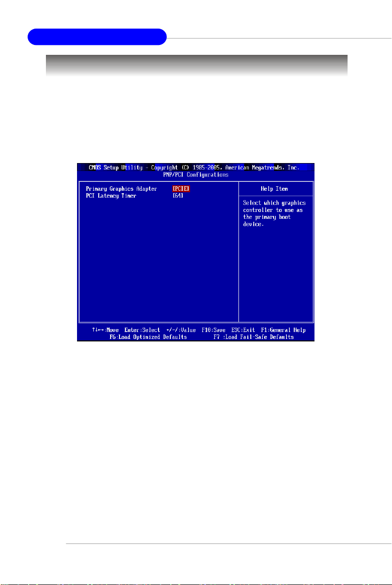
PNP/PCI Configurations
This section describes configuring the PCI bus system and PnP (Plug & Play) feature.
PCI, or Peripheral Component Interconnect, is a system which allows I/O devices to
operate at speeds nearing the speed the CPU itself uses when communicating with
its special components. This section covers some very technical items and it is
strongly recommended that only experienced users should make any changes to the
default settings.
Primary Graphics Adapter
This setting specifies which VGA card is your primary graphics adapter.
PCI Latency Timer
This feature controls how long each PCI device can hold the bus before another
takes over. The larger the value, the longer the PCI device can retain control of the
bus. As each access to the bus comes with an initial delay before any transaction
can be made, low values for the PCI Latency Timer will reduce the effective PCI
bandwidth while higher values improve it. Key in a DEC number between [0] and
[255].
3-18
Page 56

BIOS Setup
H/W Monitor
This section shows the status of your CPU, fan, overall system status, etc. Monitor
function is available only if there is hardware monitoring mechanism onboard.
Spread Spectrum
When the motherboard’s clock generator pulses, the extreme values (spikes) of the
pulses creates EMI (Electromagnetic Interference). The Spread Spectrum function
reduces the EMI generated by modulating the pulses so that the spikes of the pulses
are reduced to flatter curves.
MSI Reminds You...
1.If you do not have any EMI problem, leave the setting at [Disabled]
for optimal system stability and performance. But if you are plagued
by EMI, select the value of Spread Spectrum for EMI reduction.
2.The greater the Spread Spectrum value is, the greater the EMI is
reduced, and the system will become less stable. For the most
suitable Spread Spectrum value, please consult your local EMI
regulation.
3.Remember to disable Spread Spectrum if you are overclocking
because even a slight jitter can introduce a temporary boost in
clock speed which may just cause your overclocked processor to
lock up.
3-19
Page 57

MS-7173 M-ATX Mainboard
Auto Disable PCI Clock
This item is used to auto detect the PCI slots. When set to [Enabled], the system will
remove (turn off) clocks from empty PCI slots to minimize the electromagnetic interference (EMI). Settings: [Enabled], [Disabled].
CPU Shutdown Temperature
If the CPU temperature reaches the limit preset in this setting, the system will shotdown
automatically.
Smart FAN
Smart Fan is an excellent feature which will adjust the CPU fan speed automatically
depending on the CPU current temperature, preventing your system from being
damaged by overheating.
CPU Fan Failure Warning
When enabled, the system will automatically monitor the CPU fan during boot-up. If it
detects that the CPU fan is not rotating, the system will show an error message on
the screen and halt the boot-up process. The function is built with CPU fan power
connector (CFAN1) only and enables you to protect the CPU from possible overheating problem. If you don’t connect the CPU fan to the CPU fan power connector,
we recommend disabling the feature. Settings: [Enabled], [Disabled].
PC Health Status
Press <Enter> and the following sub-menu appears.
CPU/System Temperature, System/CPU Fan Speed, CPU Vcore, +3.3V,
+5V, +12V
These items display the current status of all of the monitored hardware devices/components such as CPU voltage, temperatures and all fans’ speeds.
3-20
Page 58

BIOS Setup
Load Optimized Defaults
The Optimized Defaults are the default values set by the mainboard manufacturer
specifically for optimal performance of the mainboard.
When you select Load Optimized Defaults, a message as below appears:
Pressing Y loads the default factory settings for optimal system performance.
BIOS Setting Password
When you select this function, a message as below will appear on the screen:
Type the password, up to 8 characters in length, and press <Enter>. The password
typed now will replace any previously set password from CMOS memory. You will
be prompted to confirm the password. Retype the password and press <Enter>. You
may also press <Esc> to abort the selection and not enter a password.
To clear a set password, just press <Enter> when you are prompted to enter the
password. A message will show up confirming the password will be disabled. Once
the password is disabled, the system will boot and you can enter Setup without
entering any password.
When a password has been set, you will be prompted to enter it every time you try
to enter Setup. This prevents an unauthorized person from changing any part of your
system configuration.
3-21
Page 59

Realtek ALC880 8-Channel Audio
Appendix A: Realtek ALC880 8-Channel Audio Function
The mainboard is equipped with Realtek ALC880 chip, which provides support for
8-channel audio output, including 2 Front, 2 Rear, 1 Center and 1 Subwoofer channel.
ALC880 allows the board to attach 2, 4, 6 or 8 speakers for better surround sound
effect. The section will tell you how to install and use 2-, 4-, 6- or 8-channel audio
function on the board.
A-1
Page 60

MS-7173 M-ATX Mainboard
Installing the Realtek HD Audio Driver
You need to install the driver for Realtek ALC880 codec to function properly before
you can get access to 2-, 4-, 6- or 8- channel audio operations. Follow the procedures described below to install the drivers for different operating systems.
Installation for Windows 2000/XP
For Windows® 2000, you must install Windows® 2000 Service Pack4 or later before
installing the driver. And for Windows® XP, you must install Windows® XP Service
Pack1 or later before installing the driver.
The following illustrations are based on Windows® XP environment and could look
slightly different if you install the drivers in different operating systems.
1. Insert the companion CD into the CD-ROM drive. The setup screen will automatically appear.
2. Click Realtek HD Audio Driver .
A-2
Click here
MSI Reminds You...
The HD Audio Configuration software utility is under continuous
update to enhance audio application. Hence, the program screens
shown here in this appendix may be slightly different from the latest
software utility and shall be held for reference only.
Page 61

Realtek ALC880 8-Channel Audio
3. Click Next to install the Realtek High Definition Audio Driver.
Click here
4. Click Finish to restart the system.
Select this
option
Click here
A-3
Page 62

MS-7173 M-ATX Mainboard
Software Configuration
After installing the audio driver, you are able to use the 2-, 4-, 6- or 8- channel audio
feature now. Click the audio icon from the system tray at the lower-right corner of
the screen to activate the HD Audio Configuration. It is also available to enable the
audio driver by clicking the Azalia HD Sound Effect Manager from the Control
Panel.
Double click
A-4
Page 63

Realtek ALC880 8-Channel Audio
Sound Effect
Here you can select a sound effect you like from the Environment list.
Load EQ Setting
Reset EQ Setting
EQ Setting On/Off
Save Preset
Delete EQ
Setting
You may choose the provided sound effects, and the equalizer will adjust automatically.
If you like, you may also load an equalizer setting or make an new equalizer setting to
save as an new one by using the “ Load EQ Setting” and “Save Preset ” button,
click “Reset EQ Setting” button to use the default value, or click “Delete EQ Set-
ting” button to remove a preset EQ setting.
There are also other pre-set equalizer models for you to choose by clicking “Others”
under the Equalizer part.
Environment Simulation
You will be able to enjoy different sound experience by pulling down the arrow,
totally 23 kinds of sound effect will be shown for selection. Realtek HD Audio Sound
Manager also provides five popular settings “Stone Corridor” , “Bathroom”, “Sewer
pipe”, “Arena” and “Audio Corridor” for quick enjoyment.
A-5
Page 64

MS-7173 M-ATX Mainboard
Equalizer Selection
Equalizer frees users from default settings; users may create their own preferred
settings by utilizing this tool.
10 bands of equalizer, ranging from 100Hz to 16KHz.
Save
The settings are
saved permanently for
future use
Enable / Disable
To disable, you can temporarily stop the sound
effect without losing the
settings
Delete
To delete the pre-saved settings which are created from previous steps.
Reset
10 bands of equalizer
would go back to the
default setting
Load
Whenever you would like
to use preload settings,
simply click this, the whole
list will be shown for your
selection.
A-6
Page 65

Realtek ALC880 8-Channel Audio
Frequently Used Equalizer Setting
Realtek HD Audio Sound Manager provides you certain optimized equalizer settings
that are frequently used for your quick enjoyment.
[How to Use It]
Other than the buttons “Pop” “Live” “Club” & “Rock” shown on the page, to pull down
the arrow in “Others” , you will find more optimized settings available to you.
Karaoke Mode
Karaoke mode brings Karaoke fun back home. Simply using the music you usually
play, Karaoke mode can help you eliminate the vocal of the song or adjust the key to
accommodate your range.
1. Vocal Cancellation: Single click on “Voice Cancellation” , the vocal of the song
wouldbe eliminated, while the background music is still in place, and you
can be that singer!
2. Key Adjustment: Using “Up / Down Arrow” to find a key which better fits your
vocal range.
Remove the
human voice
Raise the key
Lower the key
A-7
Page 66

MS-7173 M-ATX Mainboard
Mixer
In the Mixer part, you may adjust the volumes of the rear and front panels individually.
1. Playback
You can adjust the volume of the speakers that you pluged in front or rear panel by
select the Realtek HD Audio rear output or Realtek HD Audio front output
items.
MSI Reminds You...
Before set up, please make sure the playback devices are well plugged
in the jacks on the rear or front panel. The Realtek HD Audio front
output item will appear after you pluging the speakers into the jacks
on the front panel.
2. Multi-Stream Function
ALC880 supports an outstanding feature called Multi-Stream, which means you may
play different audio sources simultaneously and let them output respectively from the
indicated real panel or front panel. This feature is very helpful when 2 people are
using the same computer together for different purposes.
Click the button and the Mixer ToolBox menu will appear. Then check the Enable
playback multi-streaming and click OK to save the setup.
MSI Reminds You...
We strongly recommend that you plug the speakers into the audio jacks
on the back & front panels before enabling the multi-stream function.
A-8
Page 67

Realtek ALC880 8-Channel Audio
When you are playing the first audio source (for example: use Windows Media Player
to play DVD/VCD), the output will be played from the rear panel, which is the default
setting.
Then you must to select the Realtek HD Audio front output from the scroll list
first, and use a different program to play the second audio source (for example: use
Winamp to play MP3 files). You will find that the second audio source (MP3 music) will
come out from the Line-Out audio jack of Front Panel.
A-9
Page 68

MS-7173 M-ATX Mainboard
3. Playback control
Tool Mute
Playback device
This function is to let you freely decide which ports to
output the sound. And this is essential when multistreaming playback enabled.
Mute
You may choose to mute single or multiple volume controls or to completely mute sound
output.
Tool
Show the following volume control
This is to let you freely decide which volume control items to be displayed, total 13 items
to be chosen.
Advanced controls
Enable playback multi-streaming
With this function, you will be able to have an audio chat with your friends via head-
phone (stream 1 from front panel) while still have music (stream 2 from back panel) in
play. At any given period, you can have maximum 2 streams operating simultaneously.
A-10
Page 69

4. Recording control
Realtek ALC880 8-Channel Audio
Tool
Recording device
Back Line In/Mic, Front Line In
Realtek HD Audio Digital Input
Tool
Show the following volume controls
This is to let you freely decide which volume control items to be displayed.
Advanced controls.
Advanced control is a “Microphone Boost” icon.
Once this item is checked, you will find “advanced” icon beside “ Front Pink In” & “Mic
Volume”. With this, the input signal into “Front Pink In” & “Mic Volume” will be
strengthen.
Enable recording multi-streaming
At any given period, you can have maximum 2 streams operating simultaneously.
A-11
Page 70

MS-7173 M-ATX Mainboard
5. Recording
If you want to use microphone to record, usually the microphone is connected to the
MIC jack (the pink one) in the rear panel. You can start recording in this case. If you’d
like to connect your microphone to the front audio panel.
You may control the microphone volume by Mic Volume or front mic-in on the
mixer.
MSI Reminds You...
Only the speakers that plugged into the Line-Out jack (the green ne)
on the back panel will be functional when you intend to listen to the
audio that has been recorded from the microphone.
A-12
Page 71

Realtek ALC880 8-Channel Audio
Audio I/O
In this tab, you can easily configure your multi-channel audio function and speakers.
You can choose a desired multi-channel operation here.
a. Headphone for the common headphone
b. 2CH Speaker for Stereo-Speaker Output
c. 4CH Speaker for 4-Speaker Output
d. 6CH Speaker for 5.1-Speaker Output
e. 8CH Speaker for 8-Speaker Output (default setting)
Realtek HD Audio Manager frees you from default speaker settings. Different from
before, for each jack, they are not limited to perform certain functions. Instead, now
each jack is able to be chosen to perform either output (i.e. playback) function or input
(i.e. Recording) function, we call this “Retasking”.
Audio I/O aims to help you set jacks right. Moreover, other than blue to blue, pink to pink,
the way that you used to do, Audio I/O would guide you to other right jacks that can also
serve as microphone / speaker / headphone.
Speaker Configuration
1
Step 1: Plug in the device in any available jack.
Step 2: Dialogue “connected device” will pop up for your selection. Please select the
device you are trying to plug in.
If the device is being plugged into the correct jack, you will be able to find the icon
beside the jack changed to the one that is same as your device.
If not correct, Realtek HD Audio Manager will guide you to plug the device into the
correct jack.
A-13
Page 72

MS-7173 M-ATX Mainboard
Correct Message
Assume to plug a headphone in the Green jack at back panel. The icon beside
green jack become visible and the dialogue “ connected device” pops up.
Check the headphone, then click OK. As soon as OK is clicked, the icon
beside green jack becomes “headphone” as your selection.
Error Message
Assume to plug a headphone in the Blue jack at back panel. The icon beside
Blue jack becomes visible and the dialogue “ connected device” pops up (the
default setting of blue jack is “Line-in”. Check the headphone anyway, then
click OK. You should notice the icon beside blue jack remains the same
without any change and the error message pops.
Pop-screen check list
2CH Speakers configutaion - check the Front Speaker Out anyway.
4CH Speakers configuration - check the Front Speaker Out & Rear Speaker
6CH Speakers configuraion - check the Front Speaker Out / Rear Speaker
anyway.
8CH Speakers configuraion - check the Front Speaker Out / Rear Speaker
Speaker Out anyway.
Out anyway.
Out & Center/ Subwoofer Speaker out
Out / Center/Subwoofer Speaker out & Side
A-14
Page 73

Realtek ALC880 8-Channel Audio
Global Connector Settings
Click to access global connector settings.
1. Mute rear panel output when front headphone plugged in
Once this item is checked, whenever front headphone is plugged, the music that is
playing from the back panel, will be stopped.
2. Disable front panel jack detection (option)
Find no function on front panel jacks? Please check if front jacks on your system are
so-called AC’97 jacks. If so, please check this item to disable front panel jack
detection.
3. Enable auto popup dialogue, when device has been plugged in
Once this item is checked, the dialog “Connected device” would not automatically
pop up when device is plugged in.
A-15
Page 74

MS-7173 M-ATX Mainboard
S/PDIF
Short for Sony/Philips Digital Interface, a standard audio file transfer format. S/PDIF
allows the transfer of digital audio signals from one device to another without having to
be converted first to an analog format. Maintaining the viability of a digital signal prevents the quality of the signal from degrading when it is converted to analog.
1. Output Sampling Rate
44.1KHz: This is recommended while playing CD
48KHz: This is recommended while playing DVD or Dolby.
96KHz: This is recommended while playing DVD-Audio.
2. Output Source
Output digital audio source: The digital audio format (such as .wav, .mp3,.midi etc)
will come out through S/PDIF-Out.
S/PDIF-in to S/PDIF -out pass though mode: The data from S/PDIF-In can be real-time
played from S/PDIF-Out.
A-16
Page 75

Realtek ALC880 8-Channel Audio
Test Speakers
You can select the speaker by clicking it to test its functionality. The one you select
will light up and make testing sound. If any speaker fails to make sound, then check
whether the cable is inserted firmly to the connector or replace the bad speakers
with good ones. Or you may click the auto test button to test the sounds of
each speaker automatically.
Center
Front Left
Side Left
Rear Left
Front Right
Side Right
Subwoofer
Rear Right
A-17
Page 76

MS-7173 M-ATX Mainboard
Microphone
In this tab you may set the function of the microphone. Select the Noise Suppression to remove the possible noise during recording, or select Acoustic Echo
Cancelltion to cancel the acoustic echo druing recording.
Also, please use the drop-down list to choose the recording source from Realtek
HD Audio real input or Realtek HD Audio front input.
A-18
Page 77

Realtek ALC880 8-Channel Audio
3D Audio Demo
In this tab you may adjust your 3D positional audio before playing 3D audio applications like gaming. You may also select different environment to choose the most
suitable environment you like.
A-19
Page 78
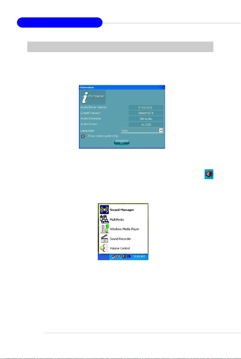
MS-7173 M-ATX Mainboard
Information
In this tab it provides some information about this HD Audio Configuration utility,
including Audio Driver Version, DirectX Version, Audio Controller & Audio Codec. You
may also select the language of this utility by choosing from the Language list.
Also there is a selection Show icon in system tray. Switch it on and an icon
will show in the system tray. Right-click on the icon and the Audio Accessories
dialogue box will appear which provides several multimedia features for you to take
advantage of.
A-20
Page 79

Realtek ALC880 8-Channel Audio
Before you begin using the front panel function, please complete the following steps:
1. Please install the pinheaders of the front panel according to Chapter 2.
2. Select AC97 or Azalia in the BIOS setting (Chapter 3).
3. If you are using Azalia setting, the microphone function on the front panel is
fixed, but the headphone jack will auto detect the device you connect and
pop-up the selection window.
4. If you are using AC97 setting, both microphone and headphone on the front
panel are fixed.
A-21
Page 80

MS-7173 M-ATX Mainboard
Using 2-, 4-, 6- & 8- Channel Audio Function
Connecting the Speakers
When you have set the Multi-Channel Audio Function mode properly in the software
utility, connect your speakers to the correct phone jacks in accordance with the
setting in software utility.
n 2-Channel Mode for Stereo-Speaker Output
Refer to the following diagram and caption for the function of each phone jack on the
back panel when 2-Channel Mode is selected.
Back Panel
1
5
4
2
6
3
1 Line In
2 Line Out (Front channels)
3 MIC
4 Line Out (Rear channels, but no functioning in this mode)
5 Line Out (Center and Subwoofer channel, but no functioning in this mode)
6 Side Surround (in 7.1CH / 5.1CH)
A-22
Page 81

n 4-Channel Mode for 4-Speaker Output
5
4
6
4-Channel Analog Audio Output
Realtek ALC880 8-Channel Audio
Back Panel
1
2
3
Description:
Connect two speakers to back
panel’ s Line Out connector and
two speakers to the real-channel Line Out connector.
1 Line In
2 Line Out (Front channels)
3 MIC
4 Line Out (Rear channels)
5 Line Out (Center and Subwoofer channel, but no functioning in this mode)
6 Side Surround (in 7.1CH / 5.1CH)
A-23
Page 82

MS-7173 M-ATX Mainboard
n 6-Channel Mode for 6-Speaker Output
6-Channel Analog Audio Output
1 Line In
2 Line Out (Front channels)
3 MIC
4 Line Out (Rear channels)
5 Line Out (Center and Subwoofer channel)
6 Side Surround (in 7.1CH / 5.1CH)
Back Panel
1
5
4
2
6
3
Description:
Connect two speakers to back
panel’ s Line Out connector, two
speakers to the rear-channel
and two speakers to the center/subwoofer-channel Line Out
connectors.
A-24
Page 83

n 8-Channel Mode for 8-Speaker Output
5
4
6
8-Channel Analog Audio Output
1 Line Out (Side channels)
2 Line Out (Front channels)
3 MIC
4 Line Out (Rear channels)
5 Line Out (Center and Subwoofer channel)
6 Side Surround (in 7.1CH / 5.1CH)
Realtek ALC880 8-Channel Audio
Back Panel
1
2
3
Description:
Connect two speakers to back
panel’s Line Out connector, two
speakers to the rear-channel,
two speakers to the center/
subwoofer-channel Line Out
connectors, and two speakers
to the side-channel Line Out
connectors.
A-25
Page 84

ATI SATA RAID Setup Guide
Appendix B: ATI SATA RAID Setup
Guide
Two major challenges facing the storage industry today are (1): keep pace with
increasing performance demands of computer systems by improving disk I/O
throughput, and (2): provide data accessibility in the event of hard disk failure.
To meet these two challenges, ATI south bridge SB400 supports four SATA ports and
incorporates Silicon Image’s SiI 3112 Serial ATA host controller, together with Silicon
Image’s Serial ATA RAID Management Software (SATARaid™).
SATARaid software provides support for RAID Striping and RAID Mirroring. RAID
Striping greatly improves hard disk I/O performance by concurrently striping data
across multiple drives. RAID Mirroring makes sure data is not lost if a drive fails as
data is simultaneously written to two drives. Drives configured for RAID Striping are
said to form a RAID 0 set, while drives configured for RAID Mirroring are said to form
a RAID 1 set.
The SATARaid software includes a Graphical User Interface (GUI) that provides
continuous monitoring of the RAID set(s) supported.
B-1
Page 85

MS-7173 M-ATX Mainboard
SATA RAID Features
u RAID 0 and RAID 1
u On-line Mirror Rebuilding
u RAID GUI Monitoring Utility:
- Displays/Logs/Alerts Users to Vital RAID Set Information
- Manages RAID Set Functions (configures, rebuilds, etc.)
u RAID Set accommodates multiple size HDDs
u HDDs function normally when not in RAID Sets
u Adjustable stripe size for RAID 0
u Automatically selects highest available transfer speed for all ATA and ATAPI
devices
u Supports:
- UDMA up to 150MB/Sec.
- All UDMA and PIO Modes
- Up to 4 SATA devices
- ACPI and ATA/ATAPI6
RAID (Redundant Array of Independent Disks) technology manages multiple disk
drives to enhance I/O performance and to provide redundancy in order to withstand
the failure of any individual member, without loss of data.
SATARaid™ provides two RAID Set types: Striped Set (RAID 0) and Mirrored Set
(RAID 1).
Disk Striping (RAID 0)
Striping is a performance-oriented, non-redundant data mapping technique. It does
not provide fault tolerance. With modern SATA and ATA bus mastering technology,
multiple I/O operations can be performed in parallel, enhancing performance. Striping
arrays use multiple disks to form a larger virtual disk.
B-2
Page 86

ATI SATA RAID Setup Guide
Disk Mirroring (RAID 1)
Disk mirroring creates an identical twin for a selected disk by having the data simultaneously written to two disks. This redundancy provides protection from a single
disk failure. If a read failure occurs on one drive, the system reads the data from the
other drive.
B-3
Page 87

MS-7173 M-ATX Mainboard
Creating RAID Sets
Creating and deleting RAID sets and performing other RAID setting up operations are
done in the BIOS. During bootup, a screen similar to the one below will appear for
about 5 seconds. Press CTRL+S or the F4 key to enter the BIOS RAID Utility.
The BIOS RAID Utility menu screen will appear. A brief description of each item on the
screen is given on the next page.
B-4
Page 88

ATI SATA RAID Setup Guide
BIOS RAID Utility Screen Description
u Main Menu
The Main Menu in the upper left corner is used to choose the operation to be performed.
The selections are:
1. Create RAID Set is used to create a new RAID Set (RAID 0 or RAID 1).
2. Delete RAID Set is used to delete a RAID Set.
3. Rebuild Mirrored Set is used to initiate the rebuild of a RAID 1 set after, for
example, a drive in the Set has been replaced.
4. Resolve Conflicts is used to automatically find the member drives of a RAID
set which has been disrupted (physical drives swapped around, for example)
and restore the Set to proper operation.
5. Low Level Format allows a single drive to have its data completely wiped
out. Drives assigned to Sets cannot be low level formatted.
These operations are described in the pages that follow.
u Help Window
This window displays context-sensitive help and status messages.
u Physical Drive Properties
This window displays the model number and capacities of the drives physically
attached to the SATA host adapter.
Description of RAID Setup Operations
u Creating RAID Sets
As previously discussed, the SATA host controller supports RAID 0 and RAID 1
configurations. The selection of the RAID configuration should be based upon factors including performance, data security, and the number of drives available. It is
best to carefully consider the long-term role of the system and plan the data storage
B-5
Page 89

MS-7173 M-ATX Mainboard
strategy. RAID sets can be created either automatically, or to allow the greatest
flexibility, manually.
1. Select “Create RAID Set.”
2. Choose a RAID 0 Striped, or a RAID 1 Mirrored set.
3. Select if you want the utility to Automatically Configure or if you want to
manually configure the RAID Set.
4. If you chose manual configuration, for Striped Sets, you can change the
chunk size. For Mirrored Sets, you assign which drive is the Source and
which is the Target.
5. The message “ Are You Sure?” will display before completing the configuration.
Answer “N” to abort the creation of the new RAID set, or “Y” to proceed with
the RAID set creation.
u Deleting RAID Sets
1. To remove one or more RAID sets, select “Delete RAID Set.”
2. Select the desired set and press Enter.
3. Press “Y” when asked “Are You Sure?”
4. The drives will be returned to the selection of logical drives from which a
new RAID set can be created
u Rebuild RAID 1 Set
This menu selection is used to initiate the copying of data from an existing drive to a
replacement drive that has been installed in a RAID 1 set after the failure of one of the
members.
1. Select “Rebuild RAID1 set.”
2. Select the desired set and press Enter.
3. Press “Y” when asked “Are You Sure?”
4. The set will be rebuilt. The status of the rebuild is displayed in the MAIN MENU
window.
u Resolving Conflicts
When a RAID set is created, the metadata written to the disk includes drive connection information including the channel on the host controller to which it is connected.
If after a drive failure the replacement drive was previously part of a RAID set or
used in another system, it may have conflicting metadata, specifically in reference to
the drive connection information. If so, this will prohibit the RAID set from being either
created or rebuilt. In order for the RAID set to function properly, this old metadata
must be first overwritten with the new metadata. To correct this, select “Resolve
Conflict”, and the correct metadata, including the correct drive connection information,
will automatically be written to the replacement drive.
B-6
Page 90

ATI SATA RAID Setup Guide
1. Select “Resolve Conflicts”
2. Select the “ Invalid RAID drive” entry in the Logical Drive Status window and
press Enter.
3. Follow the prompts to resolve the conflict.
Note that some conflict resolutions may result in the drive letter assignment changing;
for example the RAID set may have been drive D: but after the conflict resolution, it
may become drive E:. To maintain the same drive lettering, you may need to swap the
SATA cable connected to the drive, or in the case of a SATA-based removable drive
unit, you may need to change the order of the drives within the chassis.
u Low Level Formatting
The Low Level Format item selection allows you to completely erase the data on a
hard drive. However this is a very drastic process and not typically needed. Formatting the drive under Windows is usually sufficient to delete the data.
B-7
Page 91

MS-7173 M-ATX Mainboard
Installing RAID Drivers (for Windows 2000/XP only)
Installing RAID Drivers during OS Install
Follow the instructions in this section if you are performing a new installation of the
OS (Windows 2000/XP), and wish to boot from a RAID drive connected to the SATA
controller.
1. Install the new SATA drives
a. Power off the system.
b. Connect the hard drives to the RAID controller ports.
c. Insert your Windows 2000/XP CD into the CD-ROM/DVD drive, or the
2000/XP boot diskette #1 in the floppy drive if your system cannot boot
from the CD.
d. Power up the system.
2. Install the driver during OS boot
a. Press F6 for third party SCSI or driver installation at the beginning of the
text mode installation.
b. Press ‘s’ when setup asks if you want to specify an additional device,
and insert the diskette or CD labelled ‘ATI SATARaid Driver Installation
Disk’. (You’ll have to remove the OS installation CD first.)
c. Press ‘Enter’ and select ‘ATI Serial ATA Controller’
d. Press ‘Enter’ to continue with text mode setup.
3. Partition and format the Master RAID drive
a. Follow the setup instructions to select your choice of partition and file
system.
4. Install OS on the Master RAID drive
a. After setup has examined your drives, it will copy files to Windows
installation folders and restart the system.
b. The setup program will continue and finish the installation after restart.
c. Wait until Windows 2000/XP finishes installing devices, regional settings,
networking settings, components, and final set of tasks, reboot the sys-
tem if it is required.
5. Verify driver installation under Windows 2000 and XP
a. Right click on ‘My Computer’ icon, select ‘Properties’, left click on ‘Hard-
ware’ tab, and then on ‘Device Manager’ button.
b. Double click on ‘SCSI and RAID Controllers’, If there is no yellow ‘! ‘ or ‘ ?
‘ in front of ‘ATI Serial ATA Controller’, the driver is installed correctly.
Updating Previously Installed RAID Drivers
1. Insert your Windows 2000/XP ATI driver CD into the CD-ROM/DVD drive. The
ATI driver installation Wizard will start.
2. Follow the setup instructions to complete the driver installation.
B-8
Page 92

ATI SATA RAID Setup Guide
The following screen shots are taken from the ATI driver installation
wizard.
B-9
Page 93

MS-7173 M-ATX Mainboard
B-10
Page 94

ATI SATA RAID Setup Guide
Installing SATARaid Utility
Insert your Windows 2000/XP ATI driver CD into the CD-ROM/DVD drive.
Run the setup.exe program on the CD and follow the setup instructions to complete
the installation.
The following screen shots are taken from the installation of SATARaid.
B-11
Page 95

MS-7173 M-ATX Mainboard
B-12
Page 96

ATI SATA RAID Setup Guide
SATARaid GUI can be launched from the Task Bar
SATARaid GUI
The SATARaid GUI offers the user the ability to easily monitor the RAID Set. To launch
the GUI, simply double-click on the icon located in the bottom right hand corner of the
Desktop. If the icon does not appear in the bottom right hand corner of the desktop,
find where the SATARaid application was saved and launch from there. Upon launching the GUI, the main window, which identifies the computer running SATARaid,
should look the following:
Note: You must have created RAID set(s) in the BIOS as described earlier before you
can see the set(s) in the GUI.
B-13
Page 97

MS-7173 M-ATX Mainboard
A RAID 1 Set Monitoring Example
B-14
Page 98

ATI SATA RAID Setup Guide
B-15
Page 99

MS-7173 M-ATX Mainboard
B-16
Page 100
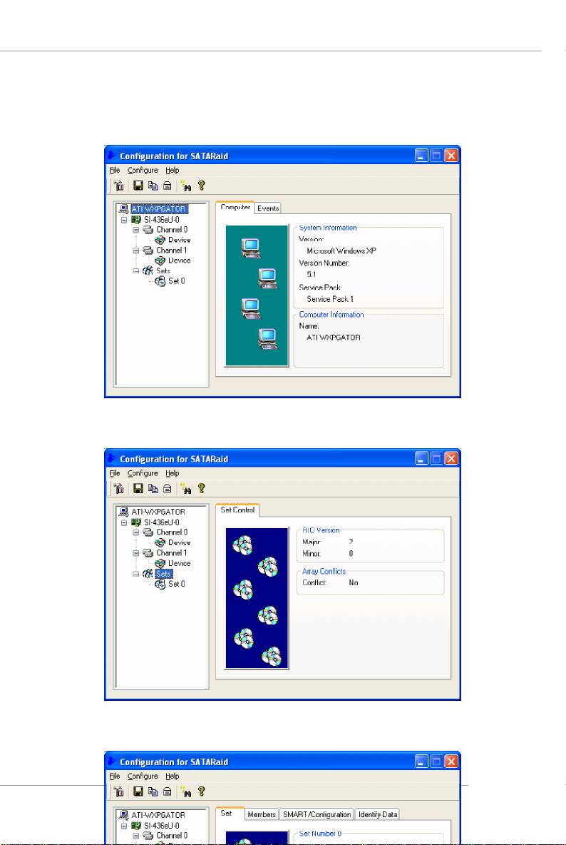
A RAID 0 Set Monitoring Example
ATI SATA RAID Setup Guide
B-17
 Loading...