

MSI P7N DIAMOND - Motherboard - ATX User Manual
P7N Diamond Series
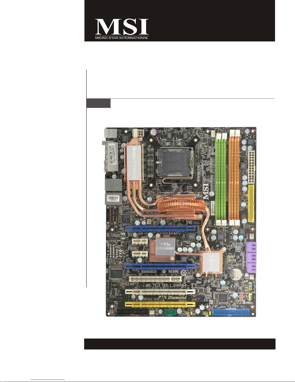
MS-7510 (V1.X) Mainboard
G52-75101X2
i

Copyright Notice
The material in this document is the intellectual property of MICRO-STAR
INTERNATIONAL. We take every care in the preparation of this document, but no
guarantee is given as to the correctness of its contents. Our products are under
continual improvement and we reserve the right to make changes without notice.
Trademarks
All trademarks are the properties of their respective owners.
NVIDIA, the NVIDIA logo, DualNet, and nForce are registered trademarks or trade-
marks of NVIDIA Corporation in the United States and/or other countries.
AMD, Athlon™, Athlon™ XP, Thoroughbred™, and Duron™ are registered trade-
marks of AMD Corporation.
Intel® and Pentium® are registered trademarks of Intel Corporation.
PS/2 and OS®/2 are registered trademarks of International Business Machines
Corporation.
Windows® 95/98/2000/NT/XP are registered trademarks of Microsoft Corporation.
Netware® is a registered trademark of Novell, Inc.
Award® is a registered trademark of Phoenix Technologies Ltd.
AMI® is a registered trademark of American Megatrends Inc.
Revision History
Revision Revision History Date
V1.0 First release February 2008
Technical Support
If a problem arises with your system and no solution can be obtained from the user’s
manual, please contact your place of purchase or local distributor. Alternatively,
please try the following help resources for further guidance.
Visit the MSI website for FAQ, technical guide, BIOS updates, driver updates,
and other information: http://global.msi.com.tw/index.php?
func=faqIndex
Contact our technical staff at: http://support.msi.com.tw/
ii
Safety Instructions
1. Always read the safety instructions carefully.
2. Keep this User’s Manual for future reference.
3. Keep this equipment away from humidity.
4. Lay this equipment on a reliable flat surface before setting it up.
5. The openings on the enclosure are for air convection hence protects the equipment from overheating. DO NOT COVER THE OPENINGS.
6. Make sure the voltage of the power source and adjust properly 110/220V before connecting the equipment to the power inlet.
7. Place the power cord such a way that people can not step on it. Do not place
anything over the power cord.
8. Always Unplug the Power Cord before inserting any add-on card or module.
9. All cautions and warnings on the equipment should be noted.
10. Never pour any liquid into the opening that could damage or cause electrical
shock.
11. If any of the following situations arises, get the equipment checked by a service
personnel:
† The power cord or plug is damaged.
† Liquid has penetrated into the equipment.
† The equipment has been exposed to moisture.
† The equipment has not work well or you can not get it work according to
User’s Manual.
† The equipment has dropped and damaged.
† The equipment has obvious sign of breakage.
12. DO NOT LEAVE THIS EQUIPMENT IN AN ENVIRONMENT UNCONDITIONED, STORAGE TEMPERATURE ABOVE 600 C (1400F), IT MAY DAMAGE THE EQUIPMENT.
CAUTION: Danger of explosion if battery is incorrectly replaced.
Replace only with the same or equivalent type recommended by the
manufacturer.
iii
FCC-B Radio Frequency Interference Statement
This equipment has been
tested and found to comply
with the limits for a Class B
digital device, pursuant to Part
15 of the FCC Rules. These limits are designed to provide reasonable protection
against harmful interference in a residential installation. This equipment generates,
uses and can radiate radio frequency energy and, if not installed and used in accor-
dance with the instructions, may cause harmful interference to radio communications.
However, there is no guarantee that interference will not occur in a particular
installation. If this equipment does cause harmful interference to radio or television
reception, which can be determined by turning the equipment off and on, the user is
encouraged to try to correct the interference by one or more of the measures listed
below.
† Reorient or relocate the receiving antenna.
† Increase the separation between the equipment and receiver.
† Connect the equipment into an outlet on a circuit different from that to
which the receiver is connected.
† Consult the dealer or an experienced radio/television technician for help.
Notice 1
The changes or modifications not expressly approved by the party responsible for
compliance could void the user’s authority to operate the equipment.
Notice 2
Shielded interface cables and A.C. power cord, if any, must be used in order to
comply with the emission limits.
VOIR LA NOTICE D ’INSTALLATION AVANT DE RACCORDER AU RESEAU.
Micro-Star International
MS-7510
This device complies with Part 15 of the FCC Rules. Operation is subject to the
following two conditions:
(1) this device may not cause harmful interference, and
(2) this device must accept any interference received, including interference that
may cause undesired operation.
iv
WEEE (Waste Electrical and Electronic Equipment) Statement
v
vi
vii

CONTENTS
Copyright Notice.........................................................................................................ii
Trademarks..................................................................................................................ii
Revision History.........................................................................................................ii
Technical Support......................................................................................................ii
Safety Instructions...................................................................................................iii
FCC-B Radio Frequency Interference Statement.............................................iv
WEEE (Waste Electrical and Electronic Equipment) Statement.......................v
English......................................................................................................................En-1
Specifications....................................................................................................En-2
Central Processing Unit: CPU...........................................................................En-5
Memory...............................................................................................................En-7
Connectors, Jumpers, Slots.............................................................................En-9
Back Panel........................................................................................................En-19
LED Status indicators......................................................................................En-21
BIOS Setup.......................................................................................................En-22
Software Information......................................................................................En-26
Deutsch....................................................................................................................De-1
Spezifikationen..................................................................................................De-2
Hauptprozessor: CPU.......................................................................................De-5
Speicher.............................................................................................................De-7
Anschlüsse, Steckbrücken und Slots.............................................................De-9
Hinteres Anschlusspaneel.............................................................................De-19
LED Statusdikatoren........................................................................................De-21
BIOS Setup.......................................................................................................De-22
Software-Information......................................................................................De-26
Français.....................................................................................................................Fr-1
Spécificités.........................................................................................................Fr-2
Central Processing Unit: CPU............................................................................Fr-5
Mémoire...............................................................................................................Fr-7
Connecteurs, Cavaliers, Slots..........................................................................Fr-9
Panneau Arrière...............................................................................................Fr-19
Indicateur d’état LED........................................................................................Fr-21
Configuration du BIOS......................................................................................Fr-22
Information de Logiciel.....................................................................................Fr-26
Русский ....................................................................................................................Ru-1
Характеристики ...............................................................................................Ru-2
Центральный процессор (CPU).....................................................................Ru-5
Память ..............................................................................................................Ru-7
Коннекторы, перемычки, разъемы..............................................................Ru-9
Задняя панель ...............................................................................................Ru-19
Состояние идикаторов LED........................................................................Ru-21
Настройка BIOS..............................................................................................Ru-22
Сведения о программном обеспечении ...................................................Ru-26
viii

P7N Diamond
User’s Guide
English
English
En-1
MS-7510 Mainboard
Specifications
Processor Support
- Core 2 Extreme, Core 2 Quad, Core 2 Duo, Pentium 4, Pentium D
9XX, Pentium D 8XX,
- Supports 3/4 pin CPU Fan Pin-Header
- Supports EIST Technology
- Supports Hyper-Threading (HT) Technology
- Supports Intel Quad/ Dual/ Core Technology to 1333 MHz
(For the latest information about CPU, please visit
http://global.msi.com.tw/index.php?func=cpuform)
Chipset
- North Bridge: NVIDIA® nForce 780i SLI chipset
- South Bridge: NVIDIA® nForce 570i SLI chipset
Memory Support
- DDR2 533/667/800/1066 SDRAM (8GB Max)
- 4 DDR2 DIMMs (240pin / 1.8V)
(For more information on compatible components, please visit http://
global.msi.com.tw/index.php?func=testreport)
LAN
- Supports 10/100/1000 Fast Ethernet by Realtek® RTL8211BL
IEEE 1394
- Chip integrated by JMB 381
- Transfer rate is up to 400Mbps
- Supports up to 2 ports (rear x 1, front x 1)
Audio
Creative® SB X-Fi Xtreme H/W Audio Card (MS-4132)
- 24-bit / 96KHz audio quality
- 100dB SNR clarity
- Up to 7.1 CH EAX 5.0 Surround Sound
IDE
- 2 IDE controllers (IDE1 by NVIDIA nForce570i SLI, IDE2 by JMB363)
- PIO Bus Master Support Ultra DMA133/100/66 operation modes
- Supports up to 4 IDE devices
SATA
- 6 SATA II ports by nForce 570i SLI
- Supports transfer rate up to 300 MB/s
RAID
- SATA1~6 support RAID 0/ 1/ 5/ 0+1/ JBOD
En-2
Floppy
- 1 floppy port
- Supports 1 FDD with 360KB, 720KB, 1.2MB, 1.44MB and 2.88MB
Connectors
Back panel
- 1 PS/2 mouse port
- 1 PS/2 keyboard port
- 2 eSATA ports
- 6 USB 2.0 Ports
- 2 LAN jacks (10/100/1000)
- 1 1394 port
- 1 Clear CMOS button
On-Board Pinheaders/ Connectors
- 2 USB 2.0 pinheaders (4 ports)
- 1 chassis intrusion
- 1 1394 pinheader
- 6 SATAII connectors
- 1 serial port pinheader (COM1)
- 1 TPM pinheader
Slots
- 4 PCI Express x16 slots
* PCIE_1/4 supports Gen2 X16 band width
* PCIE_5 it supports Gen1 X16 band width
* PCIE_6 it supports Gen1 X8 band width
- 2 PCI Express x1 slots
- 1 PCI slot (Support 3.3V/ 5V PCI bus Interface)
English
Form Factor
- ATX (30.4cm X 24.5cm)
Mounting
- 9 mounting holes
En-3
MS-7510 Mainboard
3
En-9
C
En-19
D
En-19
2
En-7
En-12
12
D
En-19
En-19
A
En-12
B
En-19
3
13
En-9
En-20
1
En-5
F
E
En-20
18 En-18
En-13
17
En-12
14
En-11
11
4
En-9
3
En-9
8
En-10
9
En-11
5
En-9
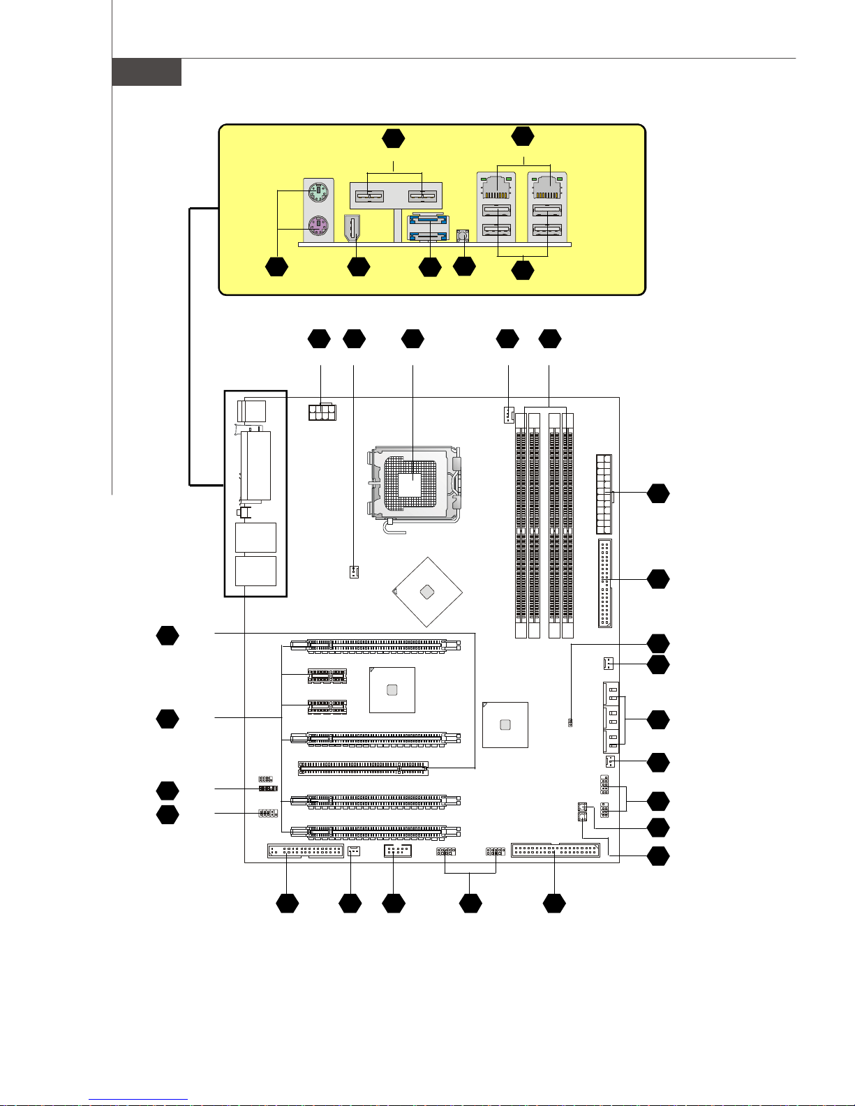
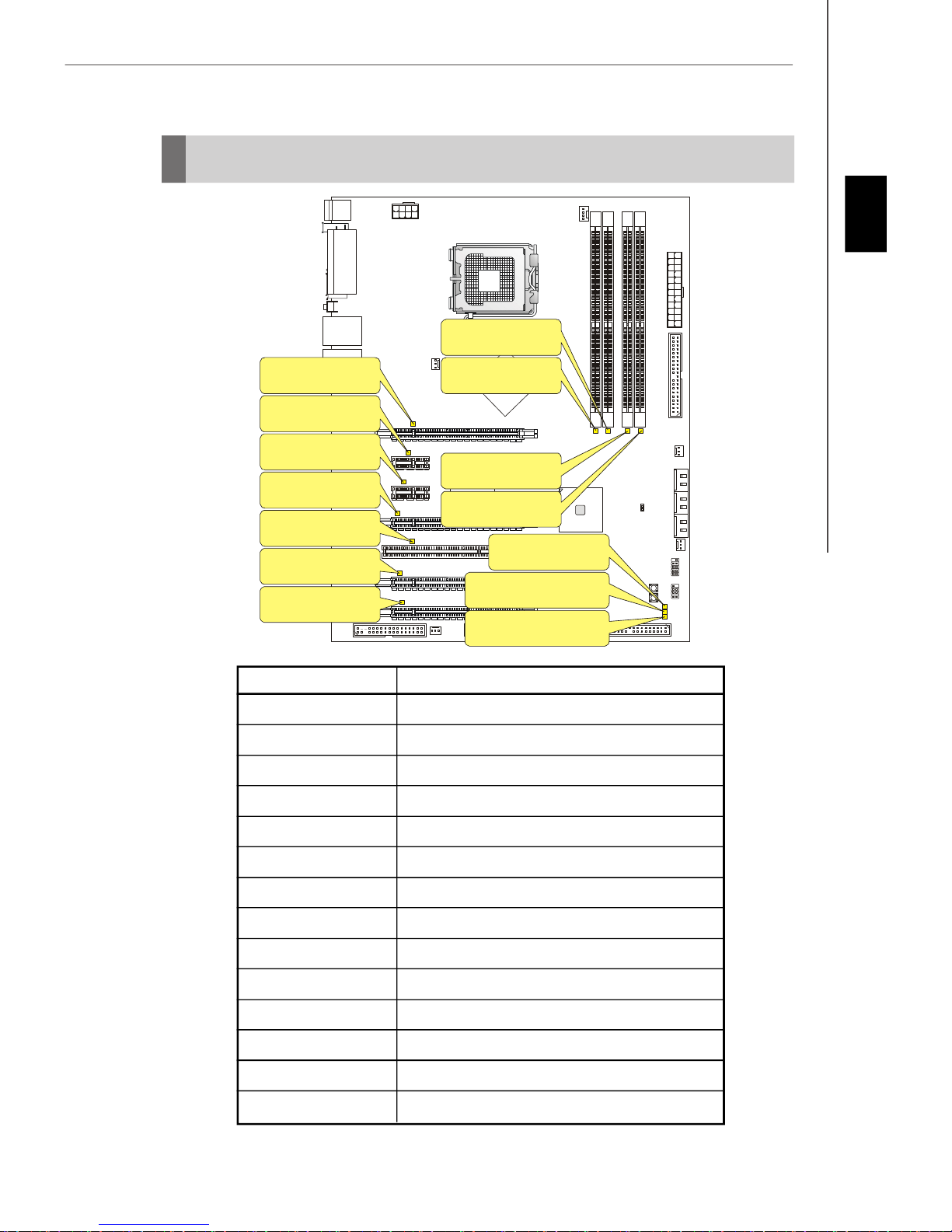
Quick Components Guide of P7N Diamond Series
(MS-7510 v1.X) Mainboard
En-9
5
10 En-11
3 En-9
En-10
6
3 En-9
En-10
7
En-13
16
15 En-13
En-4

Central Processing Unit: CPU
1
The mainboard supports Intel® processor. The mainboard uses a CPU socket called
Socket 775 for easy CPU installation. If you do not have the CPU cooler, consult your
dealer before turning on the computer.
For the latest information about CPU, please visit http://global.msi.com.tw/index.php?
func=cpuform
Important
Overheating
Overheating will seriously damage the CPU and system. Always make sure the
cooling fan can work properly to protect the CPU from overheating. Make sure
that you apply an even layer of thermal paste (or thermal tape) between the CPU
and the heatsink to enhance heat dissipation.
Replaceing the CPU
While replacing the CPU, always turn off the ATX power supply or unplug the
power supply’s power cord from the grounded outlet first to ensure the safety of
CPU.
Overclocking
This mainboard is designed to support overclocking. However, please make
sure your components are able to tolerate such abnormal setting, while doing
overclocking. Any attempt to operate beyond product specifications is not
recommended. We do not guarantee the damages or risks caused by inad-
equate operation or beyond product specifications.
English
En-5
MS-7510 Mainboard
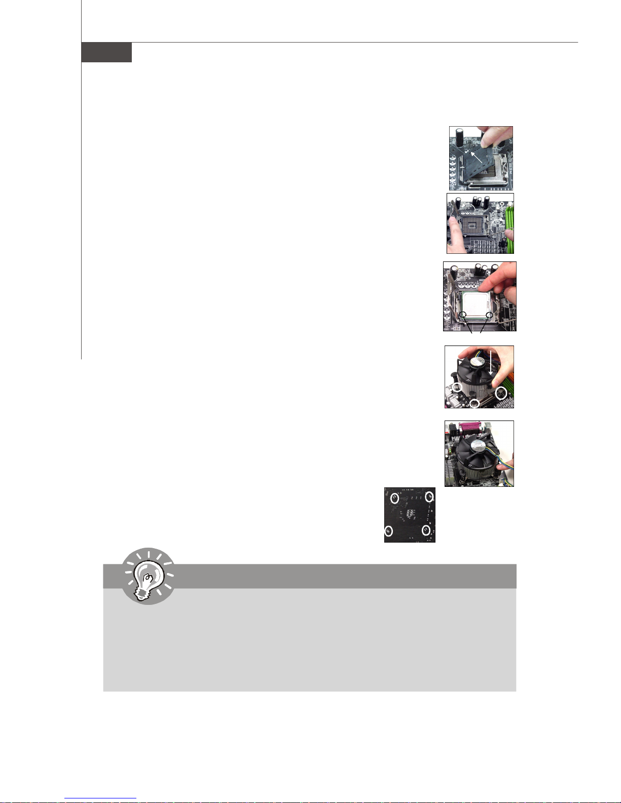
CPU & Cooler Installation Procedures for Socket 775
1. The CPU socket has a plastic cap on it to protect the contact from
damage. Before you have installed the CPU, always cover it to protect the socket pin.
2. Remove the cap from lever hinge side.
3. The pins of socket reveal.
4. Open the load lever.
5. Lift the load lever up and open the load plate.
6. After confirming the CPU direction for correct mating, put down the
CPU in the socket housing frame. Be sure to grasp on the edge of the
CPU base. Note that the alignment keys are matched.
7. Visually inspect if the CPU is seated well into the socket. If not, take
out the CPU with pure vertical motion and reinstall.
alignment key
8. Cover the load plate onto the package.
9. Press down the load lever lightly onto the load plate, and then
secure the lever with the hook under retention tab.
10.Align the holes on the mainboard with the cooler. Push down the
cooler until its four clips get wedged into the holes of the mainboard.
11.Press the four hooks down to fasten the cooler. Then rotate the
locking switch (refer to the correct direction marked on it) to lock the
hooks.
12.Turn over the mainboard to confirm that the clip-ends
are correctly inserted.
Important
1. Read the CPU status in BIOS.
2. Whenever CPU is not installed, always protect your CPU socket pin with the
plastic cap covered to avoid damaging.
3. Mainboard photos shown in this section are for demonstration of the CPU/
cooler installation only. The appearance of your mainboard may vary depending on the model you purchase.
En-6
Memory
2
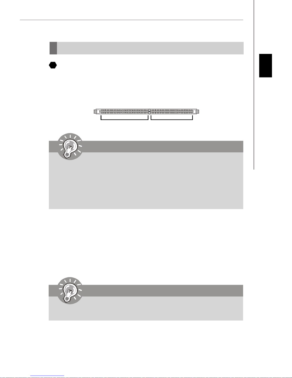
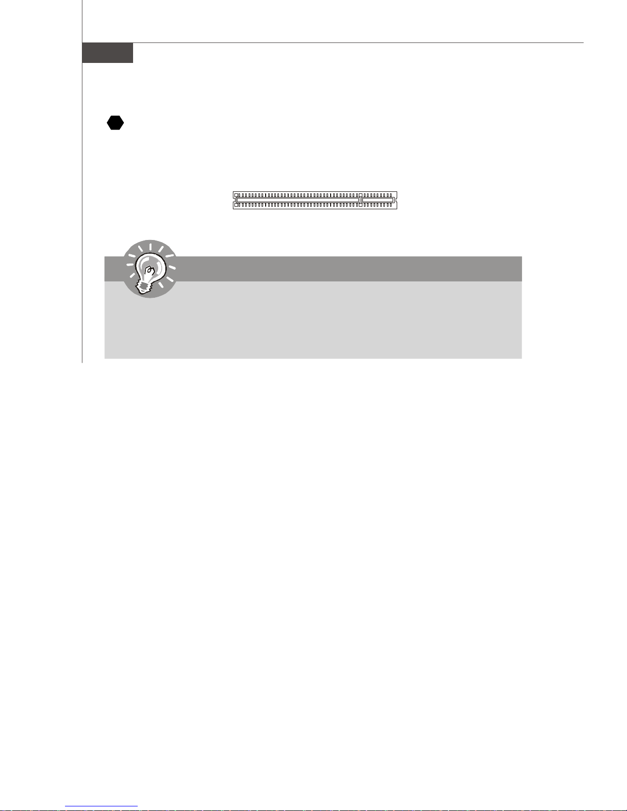
DDR2
Specification : 240-pin, 1.8v.
Single channel definition : All DIMM slots are GREEN color.
Dual channels definition : DIMM slot(s) on Channel A are marked in GREEN color.
DIMM slot(s) on Channel B are marked in Orange color.
64x2=128 pin 56x2=112 pin
Important
- DDR2 memory modules are not interchangeable with DDR and the DDR2 stan
dard is not backwards compatible. You should always install DDR2 memory
modules in the DDR2 DIMM slots.
- In Dual-Channel mode, make sure that you install memory modules of the same
type and density in different channel DIMM slots.
- To enable successful system boot-up, always insert the memory modules into the
DIMM1 first.
English
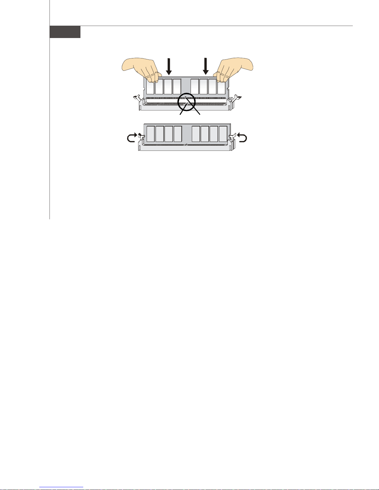
Installing Memory Modules
You can find the notch on the memory modules and the volt on the DIMM slots whether
DDR or DDR2. Follow the procedures below to install the memory module properly.
1.The memory modules has only one notch on the center and will only fit in the right
orientation.
2.Insert the memory module vertically into the DIMM slot. Then push it in until the
golden finger on the memory module is deeply inserted in the DIMM slot.
Important
You can barely see the golden finger if the memory module is properly inserted in
the DIMM slot.
3.The plastic clip at each side of the DIMM slot will automatically close.
En-7
MS-7510 Mainboard
Volt
Notch
En-8
Connectors, Jumpers, Slots
3
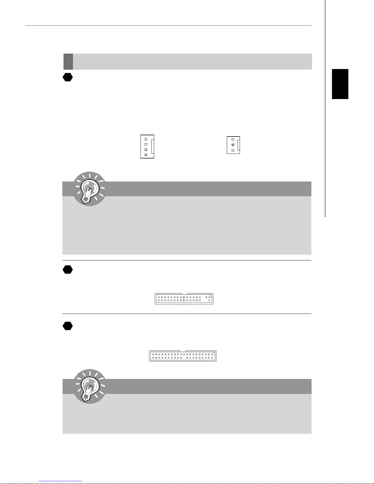
Fan Power Connectors
The fan power connectors support system cooling fan with +12V. The CPU FAN supports
Smart FAN function. When connect the wire to the connectors, always take note that the
red wire is the positive and should be connected to the +12V, the black wire is Ground
and should be connected to GND. If the mainboard has a System Hardware Monitor
chipset on-board, you must use a specially designed fan with speed sensor to take
advantage of the fan control.
English
Control
SENSOR
+12V
GND
CPU FAN
SENSOR or NC
+12V
GND
SYS FAN/ NB FAN/
POWER FAN
Important
1.Please refer to the recommended CPU fans at processor’s official website or
consult the vendors for proper CPU cooling fan.
2.CPUFAN supports fan control. You can install Dual Core Center utility that
will automatically control the CPU fan speed according to the actual CPU
temperature.
3. Fan cooler set with 3 or 4 pins power connector are both available for CPUFAN.
4
Floppy Disk Drive Connector
This connector supports 360KB, 720KB, 1.2MB, 1.44MB or 2.88MB floppy disk drive.
5
IDE connector
This connector supports IDE hard disk drives, optical disk drives and other IDE devices.
Important
If you install two IDE devices on the same cable, you must configure the drives
separately to Master/ Slave mode by setting jumpers. Refer to IDE device’s docu-
mentation supplied by the vendors for jumper setting instructions.
En-9
MS-7510 Mainboard
6
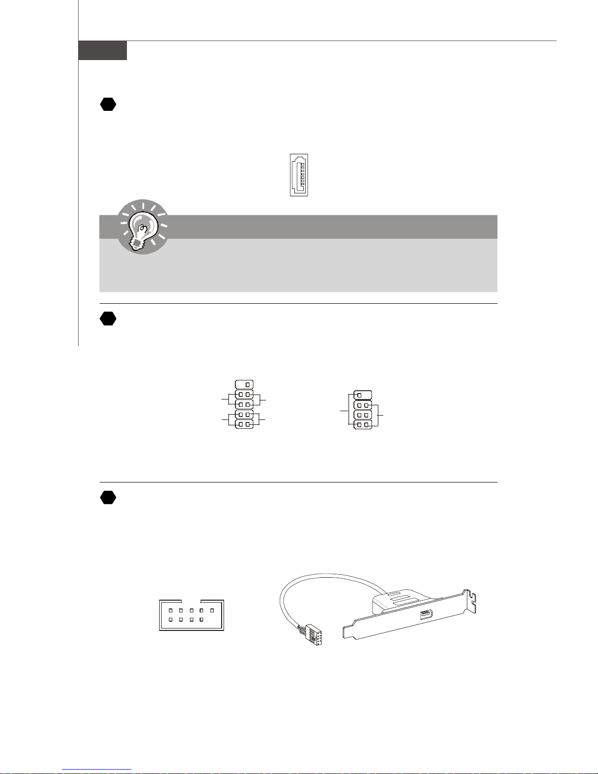
Serial ATA Connector
This connector is a high-speed Serial ATA interface port. Each connector can connect to
one Serial ATA device.
Important
Please do not fold the Serial ATA cable into 90-degree angle. Otherwise, data
loss may occur during transmission.
7
Front Panel Connectors
These connectors are for electrical connection to the front panel switches and LEDs.
The JFP1 is compliant with Intel® Front Panel I/O Connectivity Design Guide.
910
Power
Switch
Power
LED
8
IEEE1394 Connector (Green)
2
JFP1
Reset
Switch
HDD
LED
1
Speaker
78
Power LED
12
JFP2
This connector allows you to connect the IEEE1394 device via an optional IEEE1394
bracket.
IEEE1394 Bracket
(Optional)
Ground
TPB-
TPA-
2
1
TPA+
Ground
Ground
Cable power
10
9
TPB+
Key (no pin)
Cable power
En-10
9
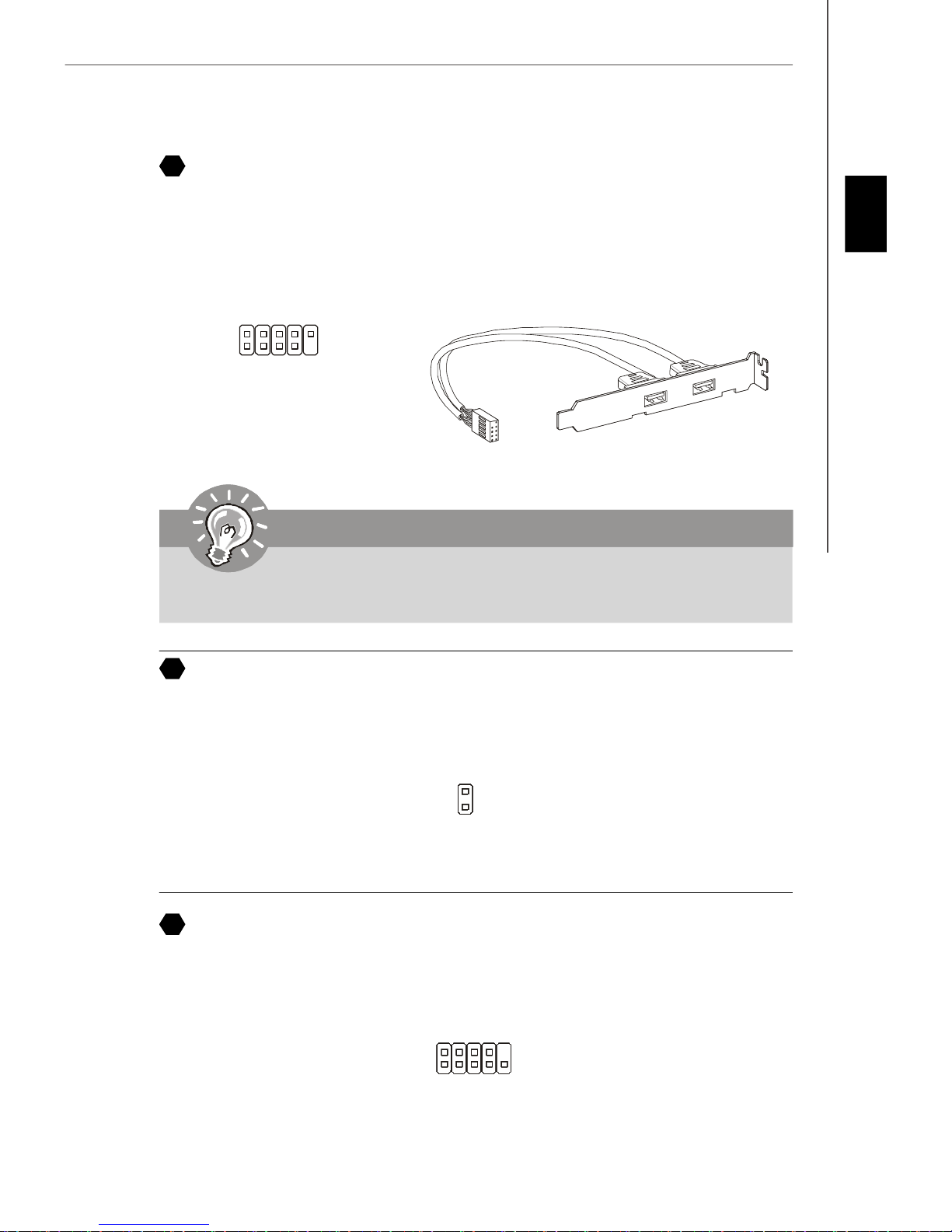
Front USB Connector (Yellow)
This connector, compliant with Intel® I/O Connectivity Design Guide, is ideal for connecting high-speed USB interface peripherals such as USB HDD, digital cameras, MP3
players, printers, modems and the like.
USB 2.0 Bracket
(Optional)
2
1
VCC
USB1-
USBOC
USB1+
GND
10
9
English
VCC
GND
USB0-
USB0+
Key (no pin)
Important
Note that the pins of VCC and GND must be connected correctly to avoid possible
damage.
10
Chassis Intrusion Connector
This connector connects to the chassis intrusion switch cable. If the chassis is opened,
the chassis intrusion mechanism will be activated. The system will record this status and
show a warning message on the screen. To clear the warning, you must enter the BIOS
utility and clear the record.
CINTRU
1
GND
2
11
Serial Port Connector
This connector is a 16550A high speed communication port that sends/receives 16
bytes FIFOs. You can attach a serial device.
SIN
CTS
DSR
2
1
DC D
SOUT DT R
10
9
RI
RTS
Ground
En-11

MS-7510 Mainboard
Power Supply Attachment
Before inserting the power supply connector, always make sure that all components are
installed properly to ensure that no damage will be caused. All power connectors on
the mainbnoard have to connect to the ATX power supply and have to work together to
ensure stable operation of the mainboard.
12
ATX 24-Pin Power Connector
This connector allows you to connect an ATX 24-pin power supply. To connect the ATX
24-pin power supply, make sure the plug of the power supply is inserted in the proper
orientation and the pins are aligned. Then push down the power supply firmly into the
connector.
You may use the 20-pin ATX power supply as you like. If you’d like to use the 20-pin ATX
power supply, please plug your power supply along with pin 1 & pin 13.
12
24
+3.3V
+12V
+12V
5VSB
PWR OK
GND
+5V
GND
+5V
GND
+3.3V
+3.3V
GND
+5V
+5V
+5V
NC
GND
GND
GND
PS-ON#
GND
-12V
+3.3V
1
13
13
ATX 12V Power Connector (2x4-Pin)
This 12V power connector is used to provide power to the CPU.
+12V
5
1
27
14
TPM module Connector
8
4
GND
This connector connects to a TPM (Trusted Platform Module) module (optional). Please
refer to the TPM security platform manual for more details and usages.
3V dual / 3 V_S TB
VCC3
SIRQ
VCC5
Key(no pi n)
GN D
GN D
2
1
LCLK
LRST#
14
13
LAD0
LAD1
LAD2
LAD3
LF RA ME#
En-12
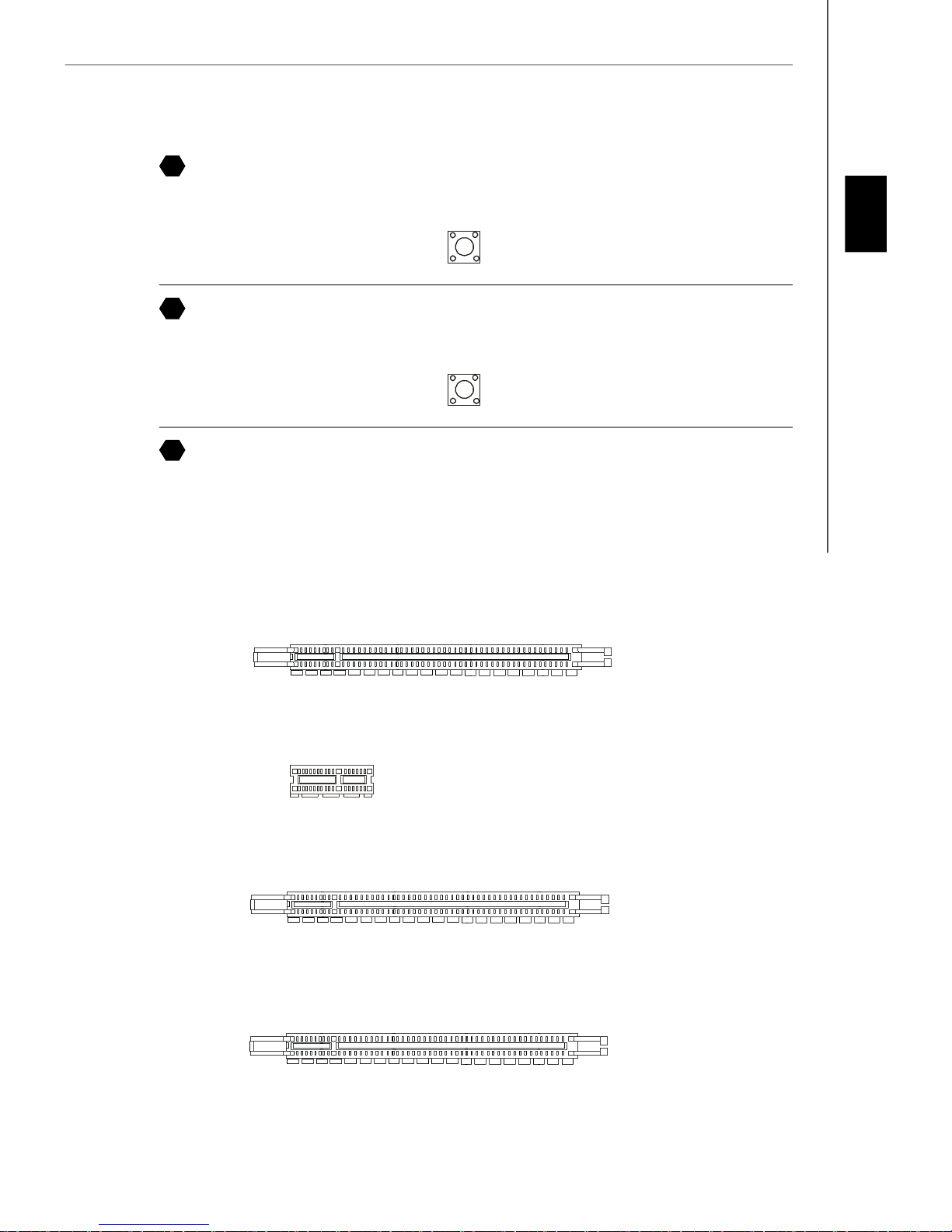
15
Power Button
This power button is used to turn-on or turn-off the system. Press the button to turn-on or
turn-off the system.
16
Reset Button
This reset button is used to reset the system. Press the button to reset the system.
17
PCI (Peripheral Component Interconnect) Express Slot
The PCI Express slot supports the PCI Express interface expansion card.
The PCI Express 2.0x 16 supports up to 8.0 GB/s transfer rate.
The PCI Express x 16 supports up to 4.0 GB/s transfer rate.
The PCI Express x 8 supports up to 2.0 GB/s transfer rate.
The PCI Express x 1 supports up to 250 MB/s transfer rate.
English
Mazarine PCI Express x16 Slots support
PCI Express 2.0x 16 speed (PCI_E1 & PCI_E4)
White PCI Express x 1 Slots support
PCI Express x 1 speed (PCI_E2 & PCI_E3)
White PCI Express x 16 Slots support
PCI Express x 16 speed (PCI_E5)
Yellow PCI Express x 16 Slots support
PCI Express x 8 speed (PCI_E6)
En-13
MS-7510 Mainboard
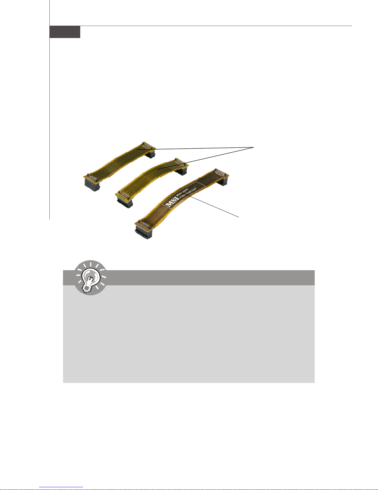
NV 3-Way SLI Technology
NVIDIA 3-Way SLI (Scalable Link Interface) technology allows three GPUs to run in
sequence within a system to achieve up to triple the performance of a single graphics
card. To utilize this technology, the three GPU cards must be connected by 3-Way SLI
bridge cables. Please refer to the following illustrations for enabling the 3-Way SLI
technology.
3-Way SLI bridge
short cable
3-Way SLI bridge
long cable
Important
Before you configure the 3-SLI platform hardware, please make sure that:
1. The three graphics cards have to support 3-Way SLI technology and they are
of the same brand and specifications;
2. The 3-Way SLI platform requires specific power supply requirement which
provide the minimum 1000W peak power to support the needs of three
graphics cards in the system;
3. The 3-Way SLI platform also requires a chassis that meet the qualifictions
for running 3-way NVIDIA SLI.
4. To visit the NVIDIA official website and find the GPUs, power supply and
chassis that should be approved for 3-Way SLI.
En-14
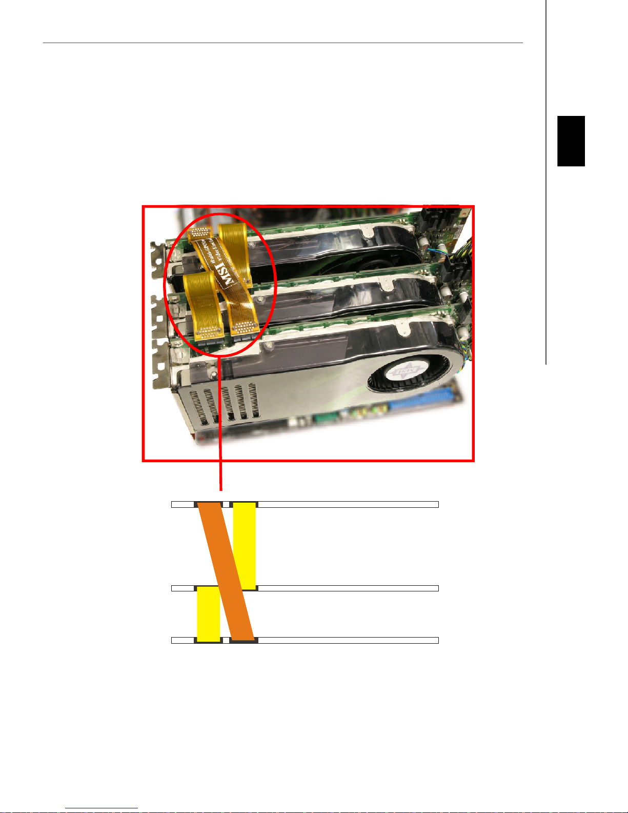
1.Installing three graphics cards which support 3-Way SLI technology on PCI Express
x16 slots. After three cards installed, SLI Bridge cables are required to connect the
golden fingers on the top of these three graphics cards (fig.1). Please note that
although you have installed three graphics cards, only the video outputs on the first
card (which be installed in PCI_E1 slot) will work. Hence, you only need to connect a
monitor to the first PCI Express card.
English
Fig.1 3-Way SLI Bridge cables connection
En-15
MS-7510 Mainboard
Important
1.Mainboard photos shown in this section are for demonstration only. The
appearance of your mainboard may vary depending on the model you purchase.
2.If you intend to install only ONE x16 graphics card, please install this
graphics card in mazarine PCIE x16 (PCI_E1) slot to run full x16 speed.
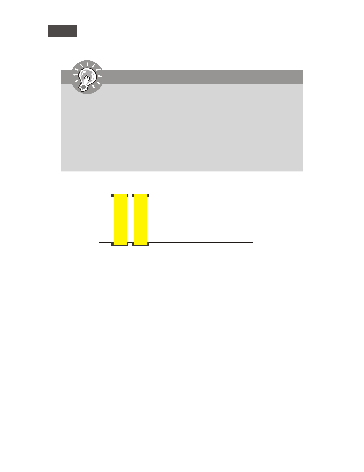
3.If you wish to use 2-way SLI, you must install the two graphics cards in
mazarine PCIE x16 slots (PCI_E1 & PCE_E4). Then, connect two graphics cards together using the 2 SLI bridge short cables (Fig.2). And remember to enable the SLI technology function as the following step 2 & step 3.
4.3-Way SLI technology supports Windows® Vista only.
Fig.2 2-Way SLI Bridge cables connection
En-16
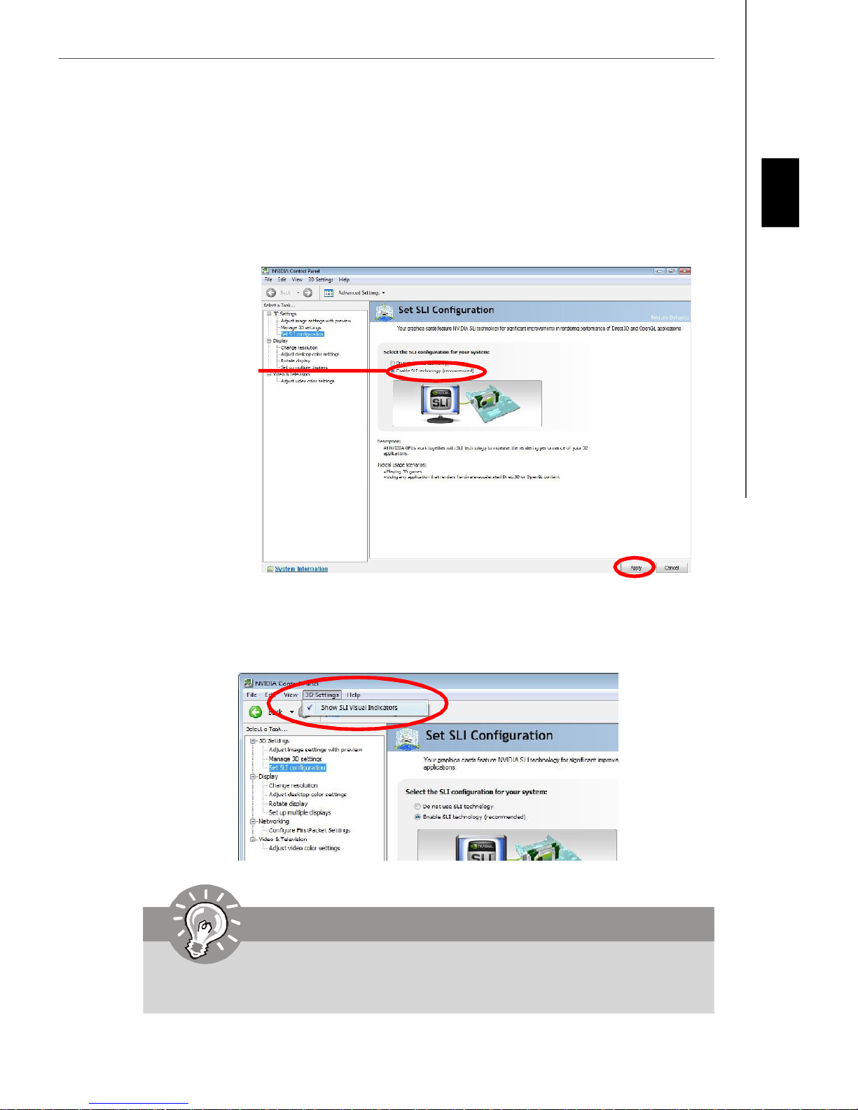
2.After the hardware installation is completed, power on the system and install the
NVIDIA ForceWare Windows Vista driver. Reboot the system, a NVIDIA Control Panel
will be provided for Multi-GPU control. Right click on windows desktop and select
NVIDIA Control Panel. Go to 3D Settings --> Set SLI configuration and check Enable
SLI technology (recommended). Then press Apply. (concerning the details of multi-
GPU settings, please refer to your graphics card manual).
Check the box
English
3.Go to 3D Settings on the top menu options, and check the Show SLI Visual
Indicators. It will show the SLI x3 lable and a scaling bar in fullscreen 3D
applications.
Important
If you want to quit the SLI function, make sure that you disable the "SLI
technology" function.
En-17
MS-7510 Mainboard
18
PCI (Peripheral Component Interconnect) Slot
The PCI slot supports LAN card, SCSI card, USB card, and other add-on cards that
comply with PCI specifications.
Important
When adding or removing expansion cards, make sure that you unplug the power
supply first. Meanwhile, read the documentation for the expansion card to configure
any necessary hardware or software settings for the expansion card, such as
jumpers, switches or BIOS configuration.
En-18
Back Panel
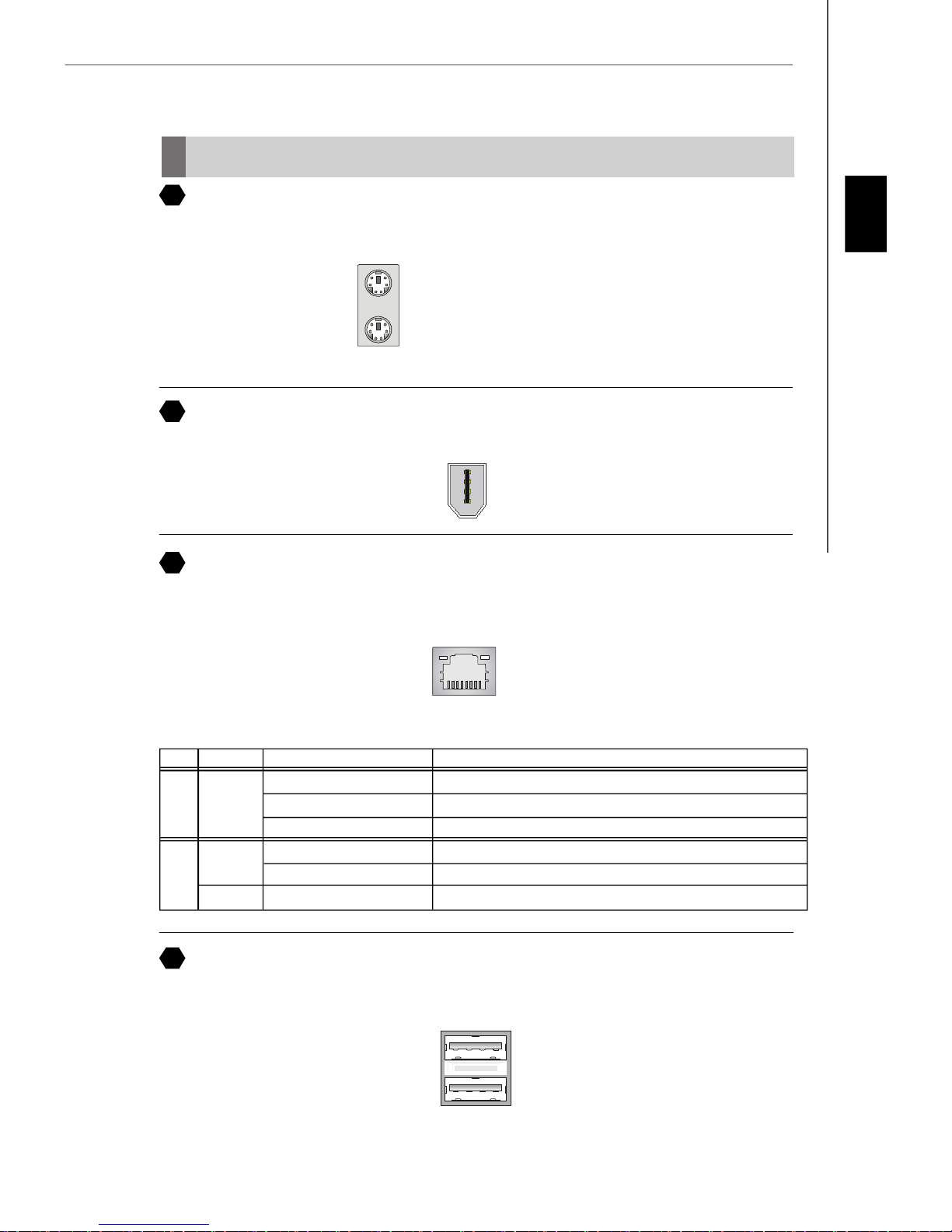
A
Mouse/Keyboard
The standard PS/2® mouse/keyboard DIN connector is for a PS/2® mouse/keyboard.
PS/2 Mouse connector (Green/ 6-pin female)
PS/2 Keyboard connector (Purple/ 6-pin female)
B
1394 Port
The IEEE1394 port on the back panel provides connection to IEEE1394 devices.
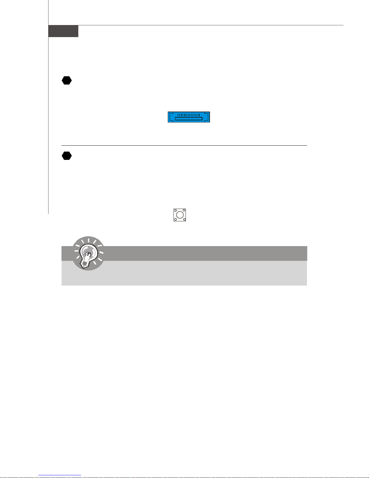
C
LAN
The standard RJ-45 LAN jack is for connection to the Local Area Network (LAN). You can
connect a network cable to it.
English
LED Color LED State Condition
Off LAN link is not established.
Left Orange On (steady state) LAN link is established.
On (brighter & pulsing) The computer is communicating with another computer on the LAN.
Green Off 10 Mbit/sec data rate is selected.
Right On 100 Mbit/sec data rate is selected.
Orange On 1000 Mbit/sec data rate is selected.
D
USB Port
The USB (Universal Serial Bus) port is for attaching USB devices such as keyboard,
mouse, or other USB-compatible devices.
En-19
MS-7510 Mainboard
E
External SATA Port
This eSATA (External Serial ATA) port is used to connect the external SATA device. You
can also use the optional external SATA cable to connect SATA device and eSATA port.
F
Clear CMOS Button
The CMOS RAM onboard has a power supply from external battery to keep the data of
system configuration. With the CMOS RAM, the system can automatically boot OS
every time it is turned on. If you want to clear the system configuration, use the button
to clear data. Press the button to clear the data.
Important
Make sure that you power off the system before clearing CMOS data.
En-20
PCIE5_LED1
PCIE6_LED1
HDD_LED1
DIMM2_LED1
DIMM3_LED1
DIMM4_LED1
POWER_LED1
STANDBY_LED1
LED Status Indicators
PCIE1_LED1
PCIE2_LED1
PCIE3_LED1
PCIE4_LED1
PCI_LED1
English
DIMM1_LED1
Name Status
PCIE1_LED1 Lights when PCI_E1 slot is functional.
PCIE2_LED1 Lights when PCI_E2 slot is functional.
PCIE3_LED1 Lights when PCI_E3 slot is functional.
PCIE4_LED1 Lights when PCI_E4 slot is functional.
PCI_LED1 Lights when PCI1 slot is functional.
PCIE5_LED1 Lights when PCI_E5 slot is functional.
PCIE6_LED1 Lights when PCI_E6 slot is functional.
DIMM1_LED1 Lights when DIMM1 slot is functional.
DIMM2_LED1 Lights when DIMM2 slot is functional.
DIMM3_LED1 Lights when DIMM3 slot is functional.
DIMM4_LED1 Lights when DIMM4 slot is functional.
HDD_LED1 Lights when HDD is functional.
POWER_LED1 Lights when system is power-on.
STANDBY_LED1 Lights when system is in standby mode.
En-21

MS-7510 Mainboard
BIOS Setup
This chapter provides basic information on the BIOS Setup program and allows you to
configure the system for optimum use. You may need to run the Setup program when:
* An error message appears on the screen during the system booting up, and requests
you to run BIOS SETUP.
* You want to change the default settings for customized features.
Important
1.The items under each BIOS category described in this chapter are under continuous update for better system performance. Therefore, the description may
be slightly different from the latest BIOS and should be held for reference only.
2.Upon boot-up, the 1st line appearing after the memory count is the BIOS
version. It is usually in the format:
A7510IMS V1.0 010108 where:
1st digit refers to BIOS maker as A = AMI, W = AWARD, and P = PHOENIX.
2nd - 5th digit refers to the model number.
6th refers to the Chipset vender as A = ATi, I = Intel, V = VIA, N = Nvidia, U = ULi.
7th - 8th digit refers to the customer as MS = all standard customers.
V1.0 refers to the BIOS version.
010108 refers to the date this BIOS was released.
En-22
 Loading...