

MSI P35 NEO2-FR - Motherboard - ATX, P35 Platinum Combo, P35 Neo2 User Manual
P35 Neo2 series
MS-7345 (v1.X) Mainboard
i

Copyright Notice
The material in this document is the intellectual property of MICRO-STAR
INTERNATIONAL. We take every care in the preparation of this document, but no
guarantee is given as to the correctness of its contents. Our products are under
continual improvement and we reserve the right to make changes without notice.
Trademarks
All trademarks are the properties of their respective owners.
NVIDIA, the NVIDIA logo, DualNet, and nForce are registered trademarks or trade-
marks of NVIDIA Corporation in the United States and/or other countries.
AMD, Athlon™ , Athlon™ XP, Thoroughbred™, and Duron™ are registered trademarks of AMD Corporation.
Intel® and Pentium® are registered trademarks of Intel Corporation.
PS/2 and OS®/2 are registered trademarks of International Business Machines
Corporation.
Windows® 95/98/2000/NT/XP/Vista are registered trademarks of Microsoft
Corporation.
Netware® is a registered trademark of Novell, Inc.
Award® is a registered trademark of Phoenix Technologies Ltd.
AMI® is a registered trademark of American Megatrends Inc.
Revision History
Revision Revision History Date
V1.0 First release for G33 March 2007
V1.1 First release for P35 March 2007
V1.2 First release for P35 Neo2 April 2007
V1.3 First release for P35 LT April 2007
Technical Support
If a problem arises with your system and no solution can be obtained from the user’s
manual, please contact your place of purchase or local distributor. Alternatively,
please try the following help resources for further guidance.
ii
Safety Instructions
1. Always read the safety instructions carefully.
2. Keep this User’s Manual for future reference.
3. Keep this equipment away from humidity.
4. Lay this equipment on a reliable flat surface before setting it up.
5. The openings on the enclosure are for air convection hence protects the equipment from overheating. DO NOT COVER THE OPENINGS.
6. Make sure the voltage of the power source and adjust properly 110/220V before connecting the equipment to the power inlet.
7. Place the power cord such a way that people can not step on it. Do not place
anything over the power cord.
8. Always Unplug the Power Cord before inserting any add-on card or module.
9. All cautions and warnings on the equipment should be noted.
10. Never pour any liquid into the opening that could damage or cause electrical
shock.
11. If any of the following situations arises, get the equipment checked by a service
personnel:
† The power cord or plug is damaged.
† Liquid has penetrated into the equipment.
† The equipment has been exposed to moisture.
† The equipment has not work well or you can not get it work according to
User’s Manual.
† The equipment has dropped and damaged.
† The equipment has obvious sign of breakage.
12. DO NOT LEAVE THIS EQUIPMENT IN AN ENVIRONMENT UNCONDITIONED, STORAGE TEMPERATURE ABOVE 600 C (1400F), IT MAY DAMAGE THE EQUIPMENT.
CAUTION: Danger of explosion if battery is incorrectly replaced.
Replace only with the same or equivalent type recommended by the
manufacturer.
iii
FCC-B Radio Frequency Interference Statement
This equipment has been
tested and found to comply
with the limits for a Class B
digital device, pursuant to Part
15 of the FCC Rules. These limits are designed to provide reasonable protection
against harmful interference in a residential installation. This equipment generates,
uses and can radiate radio frequency energy and, if not installed and used in accordance with the instructions, may cause harmful interference to radio communications.
However, there is no guarantee that interference will not occur in a particular
installation. If this equipment does cause harmful interference to radio or television
reception, which can be determined by turning the equipment off and on, the user is
encouraged to try to correct the interference by one or more of the measures listed
below.
† Reorient or relocate the receiving antenna.
† Increase the separation between the equipment and receiver.
† Connect the equipment into an outlet on a circuit different from that to
which the receiver is connected.
† Consult the dealer or an experienced radio/television technician for help.
Notice 1
The changes or modifications not expressly approved by the party responsible for
compliance could void the user’s authority to operate the equipment.
Notice 2
Shielded interface cables and A.C. power cord, if any, must be used in order to
comply with the emission limits.
VOIR LA NOTICE D’ INSTALLATION AVANT DE RACCORDER AU RESEAU.
Micro-Star International
MS-7345
This device complies with Part 15 of the FCC Rules. Operation is subject to the
following two conditions:
(1) this device may not cause harmful interference, and
(2) this device must accept any interference received, including interference that
may cause undesired operation.
iv
WEEE (Waste Electrical and Electronic Equipment) Statement
v
vi
vii

CONTENTS
Copyright Notice..............................................................................................................ii
Trademarks.......................................................................................................................ii
Revision History..............................................................................................................ii
Technical Support...........................................................................................................ii
Safety Instructions.........................................................................................................iii
FCC-B Radio Frequency Interference Statement........................................................iv
WEEE (Waste Electrical and Electronic Equipment) Statement....................................v
Chapter 1. Getting Started....................................................................................1-1
Mainboard Specifications...................................................................................1-2
Mainboard Layout................................................................................................1-4
Packing Checklist.................................................................................................1-4
Chapter 2. Hardware Setup..................................................................................2-1
Quick Components Guide....................................................................................2-2
CPU (Central Processing Unit)............................................................................2-2
Memory.................................................................................................................2-7
Power Supply......................................................................................................2-8
Back Panel...........................................................................................................2-11
Connectors........................................................................................................2-12
Jumper................................................................................................................2-19
Button.................................................................................................................2-20
Slots....................................................................................................................2-21
LED Status Indicators........................................................................................2-23
Chapter 3 BIOS Setup.............................................................................................3-1
Entering Setup.....................................................................................................3-2
The Main Menu.....................................................................................................3-4
Standard CMOS Features...................................................................................3-6
Advanced BIOS Features...................................................................................3-9
Integrated Peripherals.......................................................................................3-12
Power Management Setup...............................................................................3-14
PNP/PCI Configurations.....................................................................................3-17
H/W Monitor........................................................................................................3-19
Cell Menu............................................................................................................3-20
Load Fail-Safe/ Optimized Defaults.................................................................3-26
BIOS Setting Password.....................................................................................3-27
Appendix A Realtek ALC888/888T Audio..........................................................A-1
Installation for Windows 2000/XP......................................................................A-2
Installing the Realtek HD Audio Driver................................................................A-2
Software Configuration......................................................................................A-4
viii

Hardware Setup................................................................................................A-18
Appendix B Dual Core Center..............................................................................B-1
Activating Dual Core Center...............................................................................B-2
Main......................................................................................................................B-2
DOT (Dynamic OverClocking).............................................................................B-5
Clock.....................................................................................................................B-6
Voltage.................................................................................................................B-7
FAN Speed...........................................................................................................B-8
Temperature.........................................................................................................B-9
User Profile........................................................................................................B-10
Appendix C Intel ICH9R SATA RAID (optional)..................................................C-1
ICH9R Introduction...............................................................................................C-2
BIOS Configuration..............................................................................................C-3
Installing Driver....................................................................................................C-9
Installing Software............................................................................................C-11
RAID Migration Instructions...............................................................................C-15
Degraded RAID Array........................................................................................C-22
ix
Getting Started
Chapter 1
Getting Started
Thank you for choosing the P35 Neo2 Series (MS-7345
v1.X) ATX mainboard. The P35 Neo2 Series mainboards
are based on Intel® P35 & ICH9/ICH9R chipsets for
optimal system efficiency. Designed to fit the advanced
Intel® Core 2 Quad/Core 2 Duo/Pentium/Celeron
LGA775 processor, the P35 Neo2 Series deliver a high
performance and professional desktop platform
solution.
1-1
MS-7345 Mainboard
Mainboard Specifications
Processor Support
- Intel® Core 2 Quad/Core 2 Duo/Pentium/Celeron processors in the
LGA775 package
- Support Intel® Yorkfield, Wolfdale
(For the latest information about CPU, please visit http://global.msi.
com.tw/index.php?func=cpuform)
Supported FSB
- 1333/ 1066/ 800 MHz
Chipset
- North Bridge: Intel® P35 chipset
- South Bridge: Intel® ICH9/ICH9R Base chipset
Memory Support
- DDR2 800/667 SDRAM (8GB Max)
- 4 DDR2 DIMMs (240pin / 1.8V)
(For more information on compatible components, please visit
http://global.msi.com.tw/index.php?func=testreport)
LAN
- Supports PCIE LAN 10/100/1000 Fast Ethernet by Realtek 8111B
Audio
- Chip integrated by Realtek® ALC888/ALC888T
- Flexible 8-channel audio with jack sensing
- Compliant with Azalia 1.0 Spec
- Meet Microsoft Vista Premium spec
- Supports VoIP Card (only for ALC888T)
IDE
- 1 IDE port by Marvell 88SE6111
- Supports Ultra DMA 66/100/133 mode
- Supports PIO, Bus Master operation mode
SATA
-About ports of SATAII please check Intel website and based on PCB
version.
-About ports of e-SATA please check Intel website and be based on
PCB version.
- Supports storage and data transfers at up to 300 MB/s
1394
- Supports 1394 by VIA VT6308 (optional)
FDD
- 1 floppy port
- Supports 1 FDD with 360KB, 720KB, 1.2MB, 1.44MB and 2.88MB
1-2
Getting Started
Connectors
Back panel
- 1 PS/2 mouse port
- 1 PS/2 keyboard port
- 2 eSATA ports (optional) (eSATA functionality depends on Intel
ICH9/ICH9R support)
- 6 USB 2.0 Ports
- 1 LAN jack (10/100/1000)
- 6 flexible audio jacks
- 1 1394 port (optional)
On-Board Pinheaders / Connectors
- 3 USB 2.0 pinheaders
- 1 1394 pinheader (optional)
- 1 chasis intrusion connector
- 1 SPDIF-out pinheader
- 1 CD-in connector
- 2 HW OC pinheaders (optional)
- 1 front audio pinheader
- 1 serial pinheader
Slots
- 1 PCI Express x16 slot
- 2 PCI Express x1 slots
- 1 PCI Express x4 slot
- 2 PCI slots
- Support 3.3V/ 5V PCI bus Interface
Form Factor
- ATX (30.5cm X 24.5cm)
Mounting
- 9 mounting holes
1-3
MS-7345 Mainboard
M
M
_
A
1
M
M
_
B
1
M
M
_
A
2
M
M
_
B
2
Intel
PCI_E2
I/O Chip
SYSFAN1
SYSFAN2
J1394_1(optional)
JCI1
PCI_E4
JSLIC1(optional)
SYSFAN5
S
ATA4(op
t
ional
)
S
ATA3(op
t
ional
)
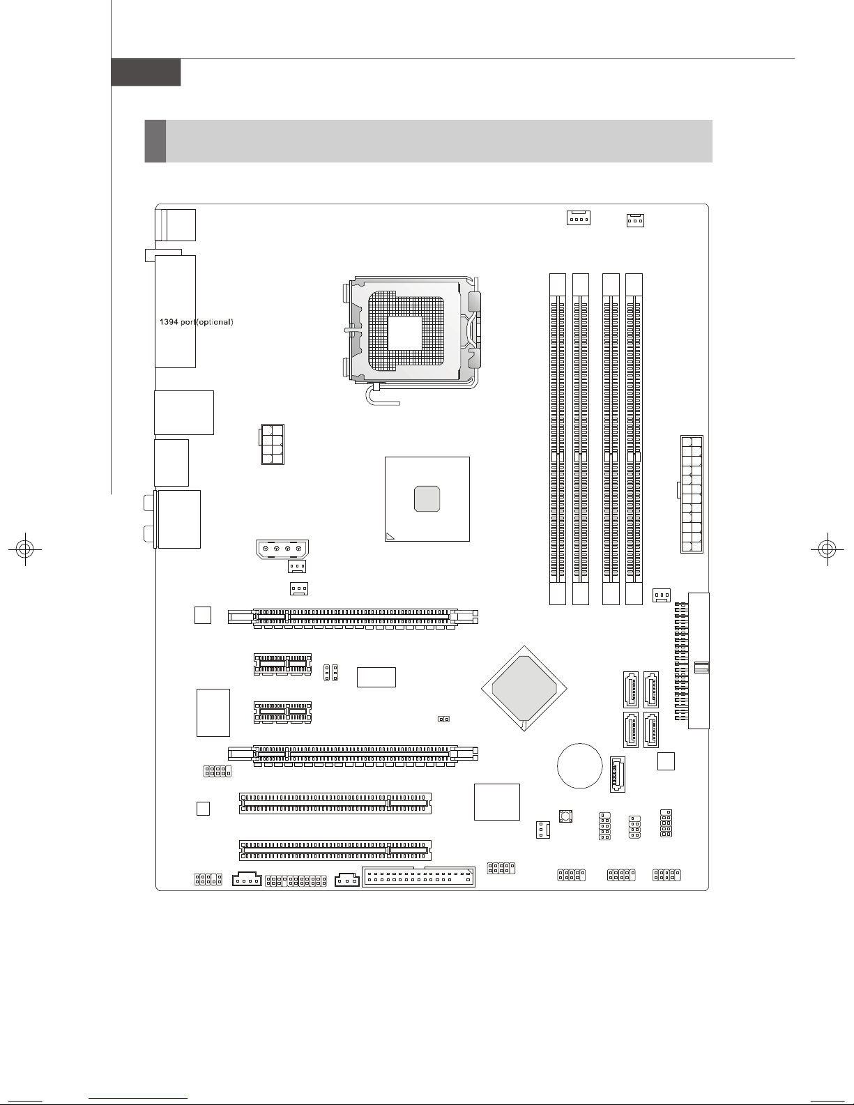
Mainboard Layout
Top : mouse
Bottom:
keyboard
Top :
USB Ports
Bottom:
Top : LAN jack
Bottom:
USB ports
eSATA ports
(optional)
T:
Line-In
M:
Line-Out
B:
Mic
T:RS-Out
M:CS-Out
B:SS-Out
POWER1
JPWR1
SYSFAN4
PCI_E3
P35
CPUFAN
1
X
T
A
3
N
A
F
S
Y
S
1-4
JCOM1
Codec
JAUD1
JCD3
PCI_E1
)
l
a
n
2
1
o
B
B
i
t
J
J
p
o
(
I
PCI 1
PCI 2
SPDO
FDD1
P35 Neo2 Series
(MS-7345 v1.X) ATX Mainboard
I
D
R
l
9
e
H
t
n
C
I
I
/
9
H
C
BATT
SW1
JUSB3 JUSB2 JUSB1
I
D
+
I
D
6
A
T
A
S
JDB1
(optional)
I
D
7
A
T
A
S
JFP2 JFP1
5
A
T
A
IDE1
S
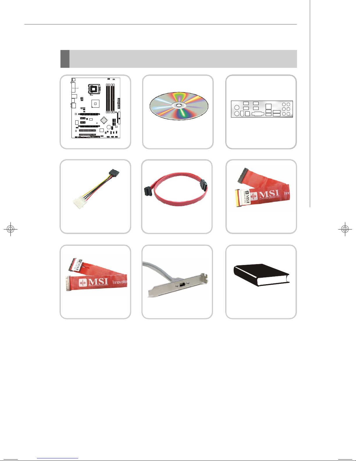
Packing Checklist
I
MM_A1
I
MM_B1
I
MM_A2
I
MM_B2
Intel
PCI_E2
I/O Chip
SYSFAN1
SYSFAN2
J1394_1(optional)
JCI1
PCI_E4
JSLIC1(optional)
SYSFAN5
SATA4(optional)SA
TA3(o
ption
a
l
)
Top : mouse
Bottom:
keyboard
Top :
USB Ports
Bottom:
Top : LAN jack
Bottom:
USB ports
eSATA ports
(optional)
POWER1
T:
Line-In
M:
Line-Out
B:
Mic
T:RS-Out
JPWR1
M:CS-Out
B:SS-Out
SYSFAN4
PCI_E3
PCI_E1
)
l
a
1
2
n
o
B
B
i
t
J
J
p
o
(
JCOM1
PCI 1
Codec
PCI 2
JCD3
SPDO
JAUD1
MSI motherboard
CPUFAN
1
X
T
l
e
t
H
n
C
I
I
/
9
H
C
I
D
D
R
9
BATT
+
SW1
JDB1
(optional)
JUSB3 JUSB2 JUSB1
A
3
N
A
F
S
Y
S
D
D
6
5
A
A
T
T
A
A
IDE1
S
S
7
A
T
A
S
JFP2 JFP1
P35
FDD1
MSI Driver/Utility CD
Getting Started
Back IO Shield
Power Cable
Floppy Cable
1394 Bracket (Optional)
SATA Cable
IDE Cable
User’s Guide
and Quick Guide
* The pictures are for reference only and may vary from the packing contents of the
product you purchased.
1-5

Hardware Setup
Chapter 2
Hardware Setup
This chapter provides you with the information about
hardware setup procedures. While doing the installation,
be careful in holding the components and follow the
installation procedures. For some components, if you
install in the wrong orientation, the components will not
work properly.
Use a grounded wrist strap before handling computer
components. Static electricity may damage the
components.
2-1
MS-7345 Mainboard
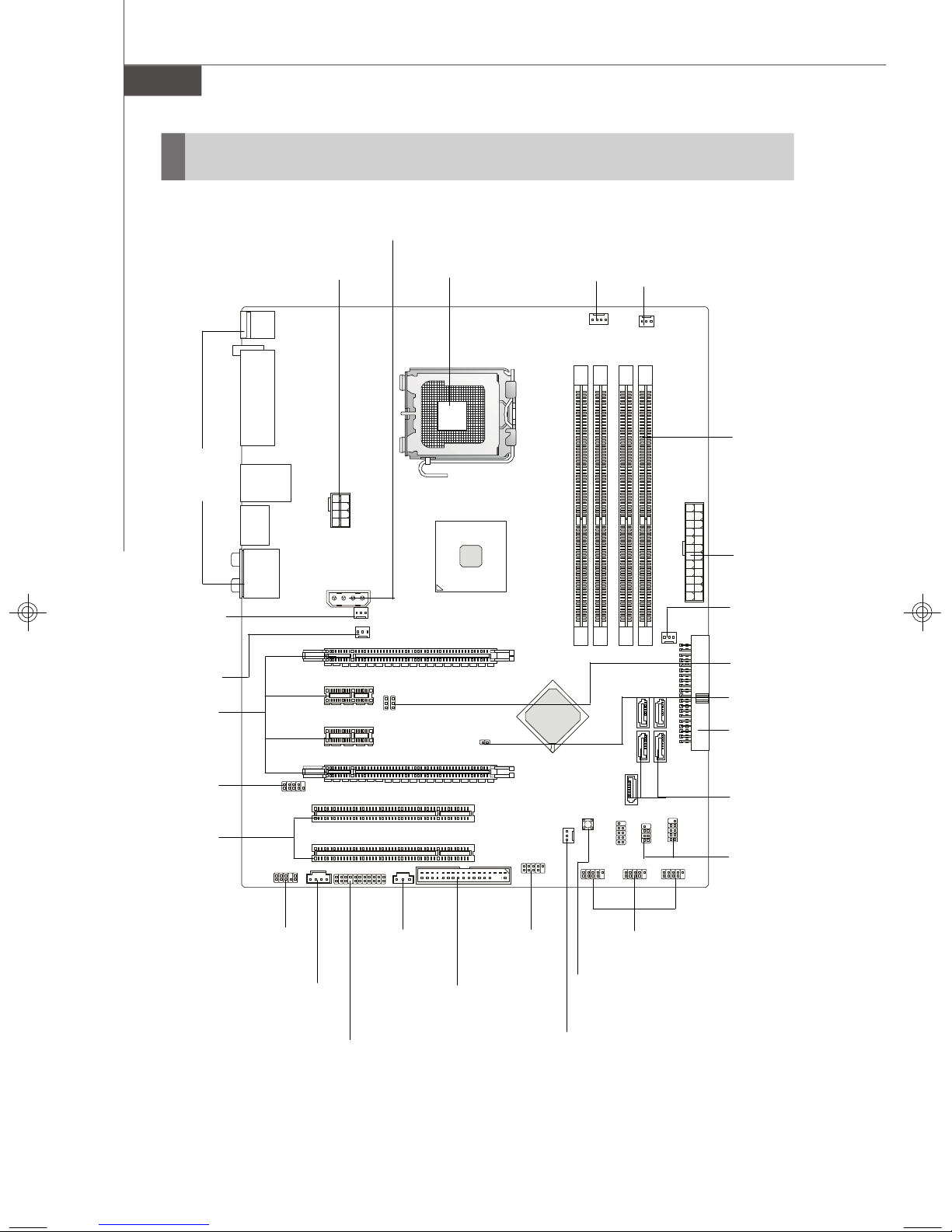
Quick Components Guide
Back Panel,
p.2-10
POWER1,
p.2-9
JPWR1,
p.2-9
CPU, p.2-3
CPUFAN,
p.2-14
SYSFAN5,
p.2-14
DDR2,
p.2-7
SYSFAN1,
p.2-14
SYSFAN4,
p.2-14
PCI_E,
p.2-21
JCOM1,
p.2-18
PCI,
p.2-21
JAUD1,
p.2-17
JCD3,
p.2-17
SPDO,
p.2-15
FDD1,
p.2-12
J1394_1,
p.2-15
ATX1,
p.2-9
SYSFAN3,
p.2-14
JB1,JB2,
p.2-19
JCI1,
p.2-14
IDE1,
p.2-12
SATAII,
p.2-13
JFP1,2,
p.2-16
JUSB1~3,
p.2-18
SW1,
p.2-20
2-2
JSLIC1,
p.2-13
SYSFAN2,
p.2-14
Hardware Setup
CPU (Central Processing Unit)
When you are installing the CPU, make sure to install the cooler to prevent
overheating. If you do not have the CPU cooler, consult your dealer before turning
on the computer.
Important
Overheating
Overheating will seriously damage the CPU and system. Always make sure
the cooling fan can work properly to protect the CPU from overheating. Make
sure that you apply an even layer of thermal paste (or thermal tape) between
the CPU and the heatsink to enhance heat dissipation.
Replaceing the CPU
While replacing the CPU, always turn off the ATX power supply or unplug the
power supply’s power cord from the grounded outlet first to ensure the safety
of CPU.
Overclocking
This mainboard is designed to support overclocking. However, please make
sure your components are able to tolerate such abnormal setting, while
doing overclocking. Any attempt to operate beyond product specifications is
not recommended. We do not guarantee the damages or risks caused
by inadequate operation or beyond product specifications.
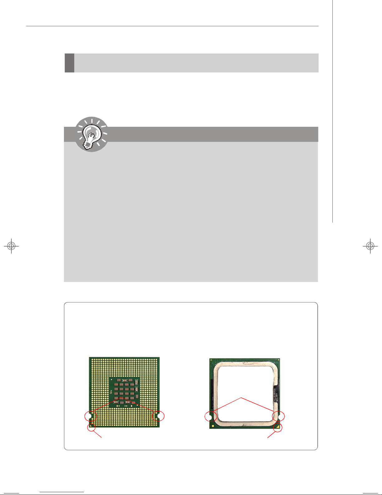
Introduction to LGA 775 CPU
The pin-pad side of LGA 775
CPU.
Alignment Key Alignment Key
Yellow triangle is the Pin 1 indicator
The surface of LGA 775 CPU.
Remember to apply some thermal paste on it for better heat
dispersion.
Yellow triangle is the Pin 1 indicator
2-3
MS-7345 Mainboard
CPU & Cooler Installation
When you are installing the CPU, make sure the CPU has a cooler attached on
the top to prevent overheating. Meanwhile, do not forget to apply some thermal
paste on CPU before installing the heat sink/cooler fan for better heat dispersion.
Follow the steps below to install the CPU & cooler correctly. Wrong installation will
cause the damage of your CPU & mainboard.
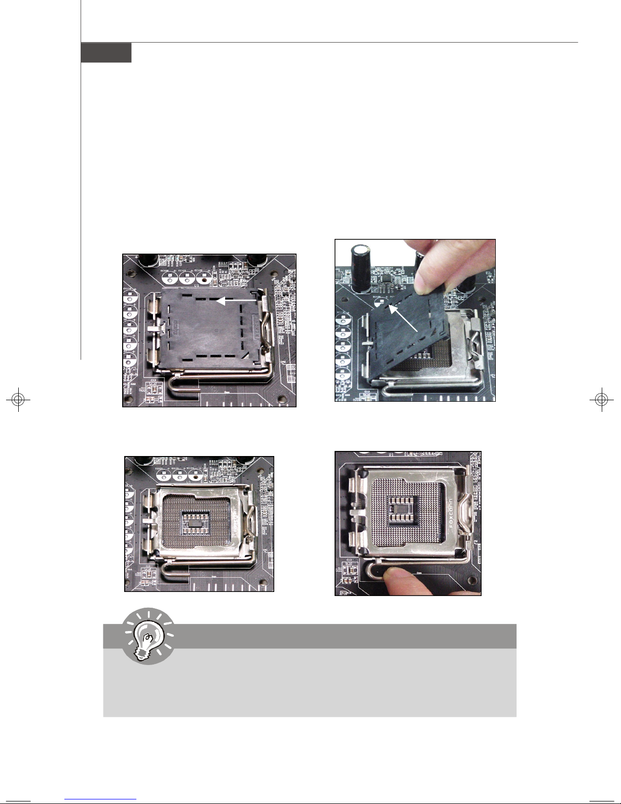
1.The CPU socket has a plastic cap on
it to protect the contact from damage.
Before you install the CPU, always
cover it to protect the socket pin.
3.The pins of socket reveal.
2.Remove the cap from lever hinge
side (as the arrow shows).
4.Open the load lever.
Important
1.Confirm if your CPU cooler is firmly installed before turning on your system.
2. Do not touch the CPU socket pins to avoid damaging.
3. The availability of the CPU land side cover depends on your CPU packing.
2-4
Hardware Setup
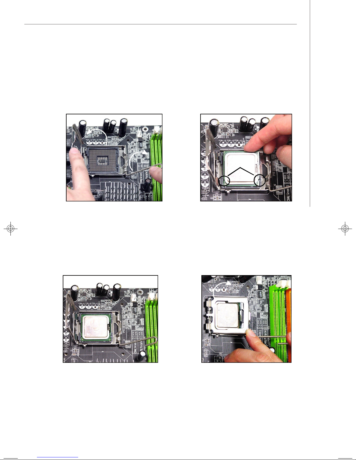
5.Lift the load lever up and open the
load plate.
6.After confirming the CPU direction
for correct mating, put down the
CPU in the socket housing frame.
Be sure to grasp on the edge of
the CPU base. Note that the alignment keys are matched.
alignment
key
7.Visually inspect if the CPU is
seated well into the socket. If not,
take out the CPU with pure vertical
motion and reinstall.
8.Cover the load plate onto the
package.
2-5
MS-7345 Mainboard
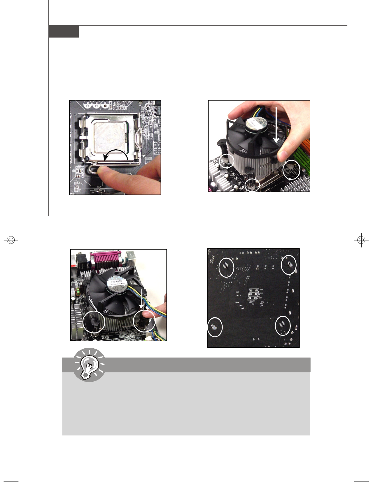
9.Press down the load lever lightly
onto the load plate, and then secure the lever with the hook under
retention tab.
11.Press the four hooks down to fas-
ten the cooler. Then rotate the locking switch (refer to the correct direction marked on it) to lock the
hooks.
10. Align the holes on the mainboard
with the heatsink. Push down the
cooler until its four clips get
wedged into the holes of the
mainboard.
12.Turn over the mainboard to confirm that the clip-ends are correctly inserted.
locking
switch
Important
1. Read the CPU status in BIOS (Chapter 3).
2. Whenever CPU is not installed, always protect your CPU socket pin with the
plastic cap covered (shown in Figure 1) to avoid damaging.
3. Mainboard photos shown in this section are for demonstration of the CPU/
cooler installation only. The appearance of your mainboard may vary depending on the model you purchase.
2-6
Hardware Setup
1
2
3
Empty
Installed
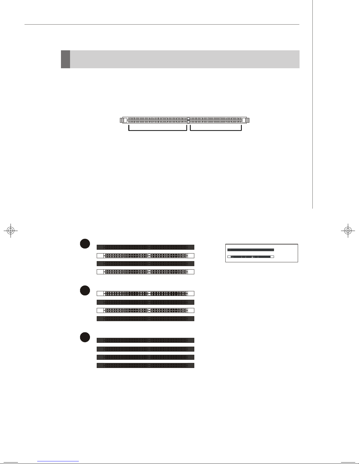
Memory
These DIMM slots are used for installing memory modules.
DDR2
240-pin, 1.8V
64x2=128 pin 56x2=112 pin
Single-Channel: All DIMMs in GREEN
Dual-Channel: Channel A in GREEN; Channel B in ORANGE
Dual-Channel mode Population Rule
In Dual-Channel mode, the memory modules can transmit and receive data with two
data bus lines simultaneously. Enabling Dual-Channel mode can enhance the system
performance. Please refer to the following illustrations for population rules under
Dual-Channel mode.
DIMM_A1
DIMM_A2
DIMM_B1
DIMM_B2
DIMM_A1
DIMM_A2
DIMM_B1
DIMM_B2
DIMM_A1
DIMM_A2
DIMM_B1
DIMM_B2
2-7
MS-7345 Mainboard
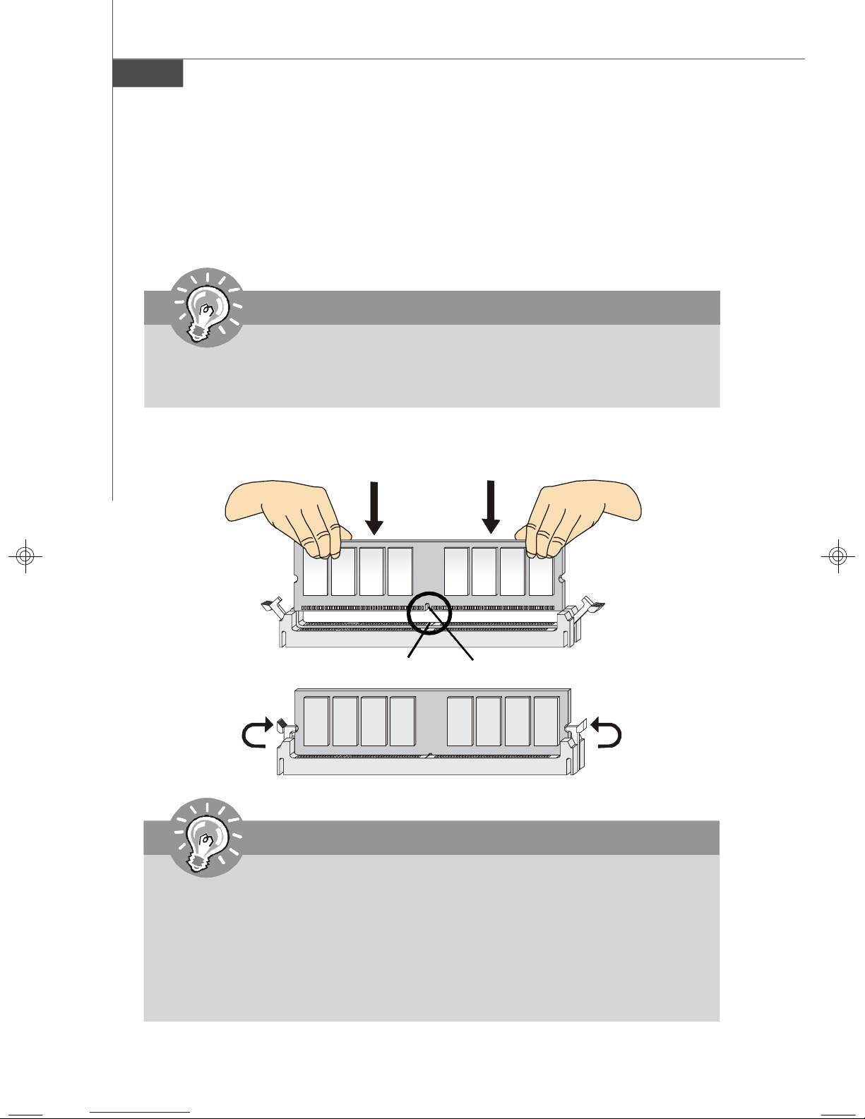
Installing Memory Modules
1. The memory module has only one notch on the center and will only fit in the right
orientation.
2. Insert the memory module vertically into the DIMM slot. Then push it in until the
golden finger on the memory module is deeply inserted in the DIMM slot.
Important
You can barely see the golden finger if the memory module is properly inserted
in the DIMM slot.
3. The plastic clip at each side of the DIMM slot will automatically close.
Volt
Notch
Important
-DDR2 memory modules are not interchangeable with DDR and the DDR2
standard is not backwards compatible. You should always install DDR2
memory modules in the DDR2 DIMM slots.
-In Dual-Channel mode, make sure that you install memory modules of the
same type and density in different channel DIMM slots.
-To enable successful system boot-up, always insert the memory modules
into the DIMM_A1 first.
2-8
Hardware Setup
Power Supply
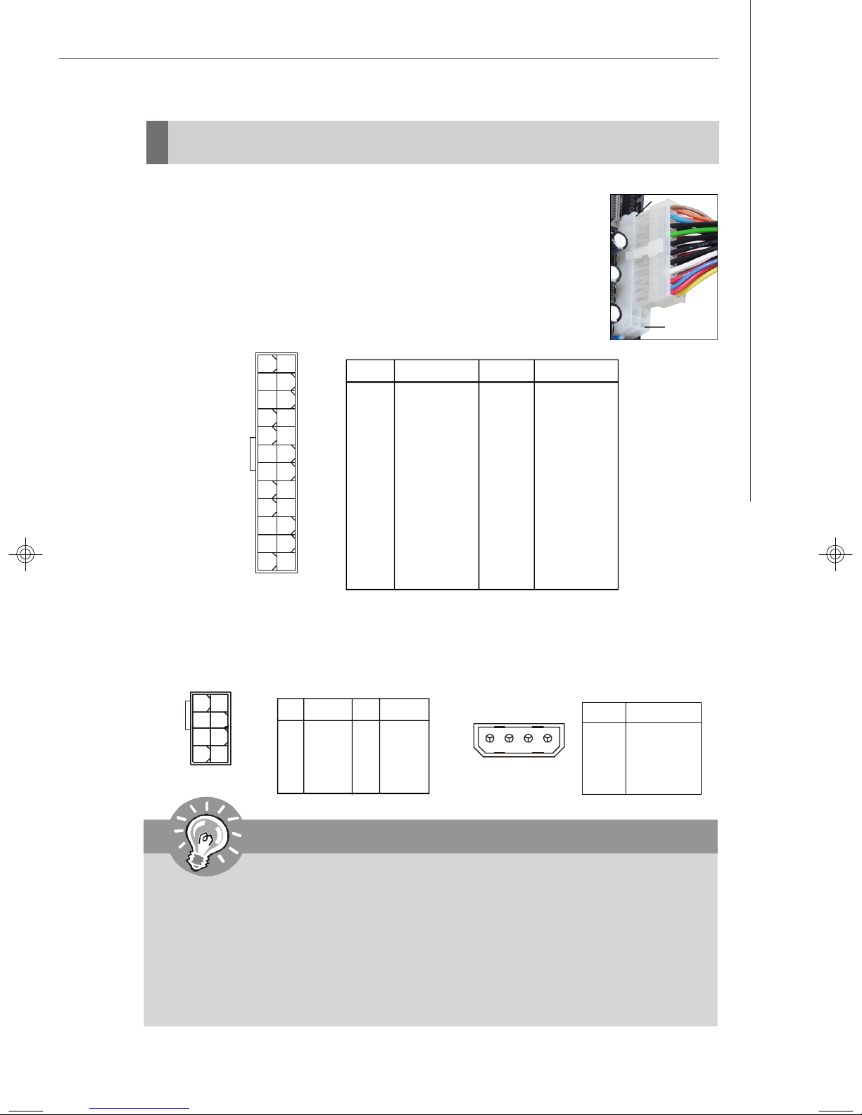
ATX 24-Pin Power Connector: ATX1
This connector allows you to connect an ATX 24-pin power supply.
To connect the ATX 24-pin power supply, make sure the plug of the
power supply is inserted in the proper orientation and the pins are
aligned. Then push down the power supply firmly into the connector.
You may use the 20-pin ATX power supply as you like. If you’d like
to use the 20-pin ATX power supply, please plug your power supply along with pin 1 & pin 13 (refer to the image at the right hand).
Pin Definition
13
ATX1
24
1
12
PIN SIGNAL
1 +3.3V
2 +3.3V
3 GND
4 +5V
5 GND
6 +5V
7 GND
8 PWR OK
9 5VSB
10 +12V
11 +12V
12 +3.3V
PIN SIGNAL
13 +3.3V
14 -12V
15 GND
16 PS-ON#
17 GND
18 GND
19 GND
20 Res
21 +5V
22 +5V
23 +5V
24 GND
pin 13
pin 12
ATX 12V Power Connector: POWER1 / JPWR1
The POWER1 12V power connector is used to provide power to the CPU. And the
JPWR1 12V power connector is used to provide power to the PCIEX16 graphics
card.
5
8
POWER1
1
4
Pin Definition
PINSIGNAL
1 GND
2 GND
3 GND
4 GND
PINSIGNAL
5 +12V
6 +12V
7 +12V
8 +12V
JPWR1
Pin Definition
1
PIN SIGNAL
1 5V
2 GND
3 GND
4 12V
Important
1. Make sure that all the connectors are connected to proper ATX power supplies to ensure stable operation of the mainboard.
2. Power supply of 350 watts (and above) is highly recommended for system
stability.
3. ATX 12V power connection should be greater than 18A.
4. If the POWER1 connector too closes the heatpipe and plug inconveniently.
You could use the bundled ATX Extender to increase connector height. It can
prevent the power cable to touch the heatpipe as well.
2-9
MS-7345 Mainboard
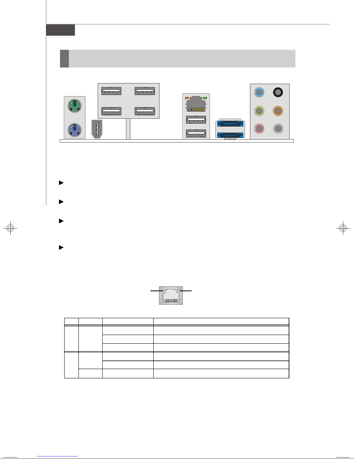
Back Panel
Mouse
USB Ports
LAN
L-In
RS-Out
eSATA Port
(optional)
Keyboard
1394 Port
L-Out
USB Ports Mic
CS-Out
SS-Out
(Optional)
Mouse/Keyboard
The standard PS/2® mouse/keyboard DIN connector is for a PS/2® mouse/keyboard.
1394 Port (Optional)
The IEEE1394 port on the back panel provides connection to IEEE1394 devices.
USB Port
The USB (Universal Serial Bus) port is for attaching USB devices such as keyboard,
mouse, or other USB-compatible devices.
LAN
The standard RJ-45 LAN jack is for connection to the Local Area Network (LAN). You
can connect a network cable to it.
Green / OrangeYellow
LED Color LED State Condition
Off LAN link is not established.
Left Yellow On (steady state) LAN link is established.
On (brighter & pulsing)The computer is communicating with another computer on the LAN.
Green Off 10 Mbit/sec data rate is selected.
Right On 100 Mbit/sec data rate is selected.
Orange On 1000 Mbit/sec data rate is selected.
2-10
Hardware Setup
Audio Ports
These audio connectors are used for audio devices. You can differentiate the color
of the audio jacks for different audio sound effects.
Line-In (Blue) - Line In is used for external CD player, tapeplayer or
other audio devices.
Line-Out (Green) - Line Out, is a connector for speakers or headphones.
Mic (Pink) - Mic, is a connector for microphones.
RS-Out (Black) - Rear-Surround Out in 4/ 5.1/ 7.1 channel mode.
CS-Out (Orange) - Center/ Subwoofer Out in 5.1/ 7.1 channel mode.
SS-Out (Gray) - Side-Surround Out 7.1 channel mode.
eSATA Port (optional)
The eSATA port is for attaching the eSATA external hard drive.
(about specification content please refer to Intel website)
2-11
MS-7345 Mainboard
Connectors
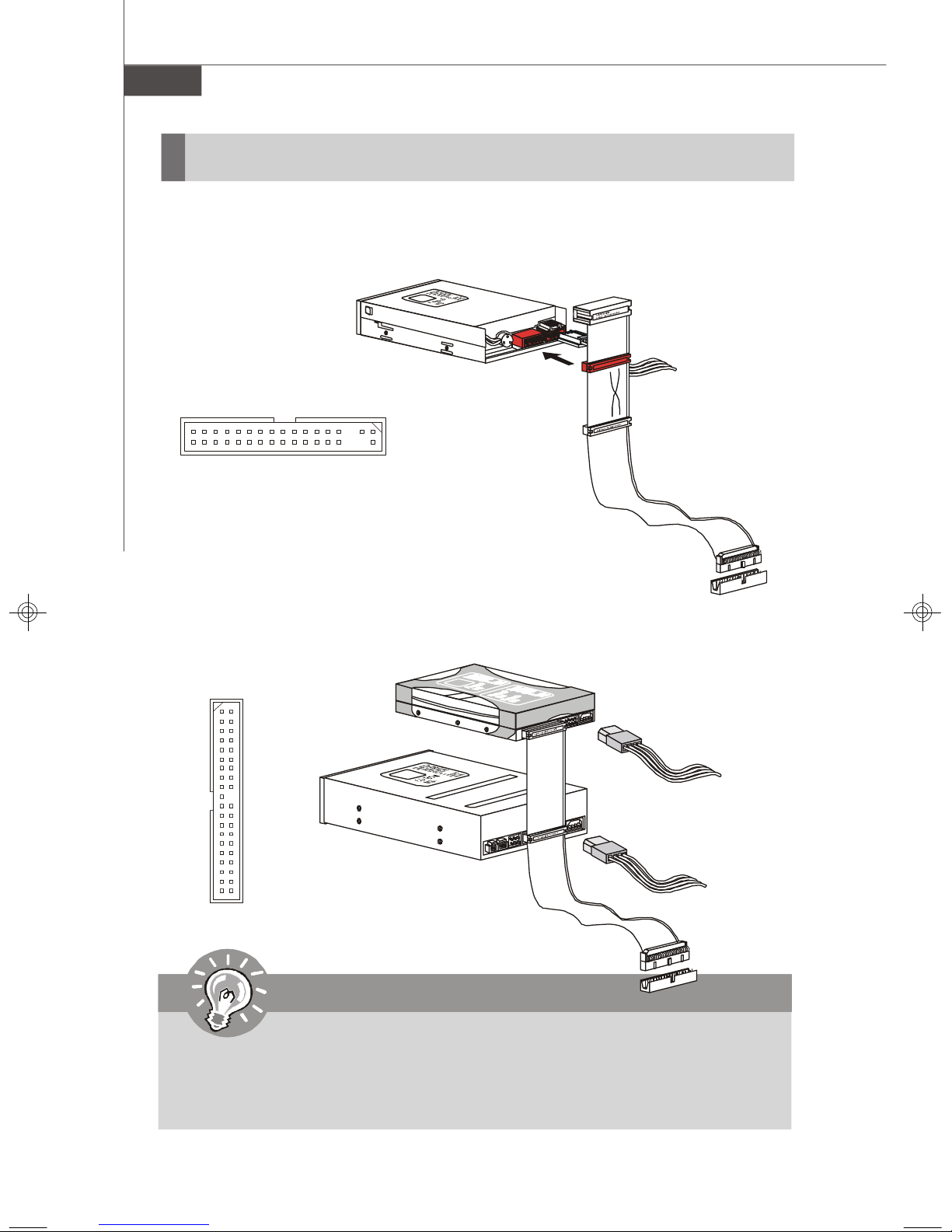
Floppy Disk Drive Connector: FDD1
This connector supports 360KB, 720KB, 1.2MB, 1.44MB or 2.88MB floppy disk drive.
FDD1
IDE Connector: IDE1
This connector supports IDE hard disk drives, optical disk drives and other IDE devices.
IDE1
Important
If you install two IDE devices on the same cable, you must configure the
drives separately to master / slave mode by setting jumpers. Refer to IDE
device’s documentation supplied by the vendors for jumper setting
instructions.
2-12
Hardware Setup
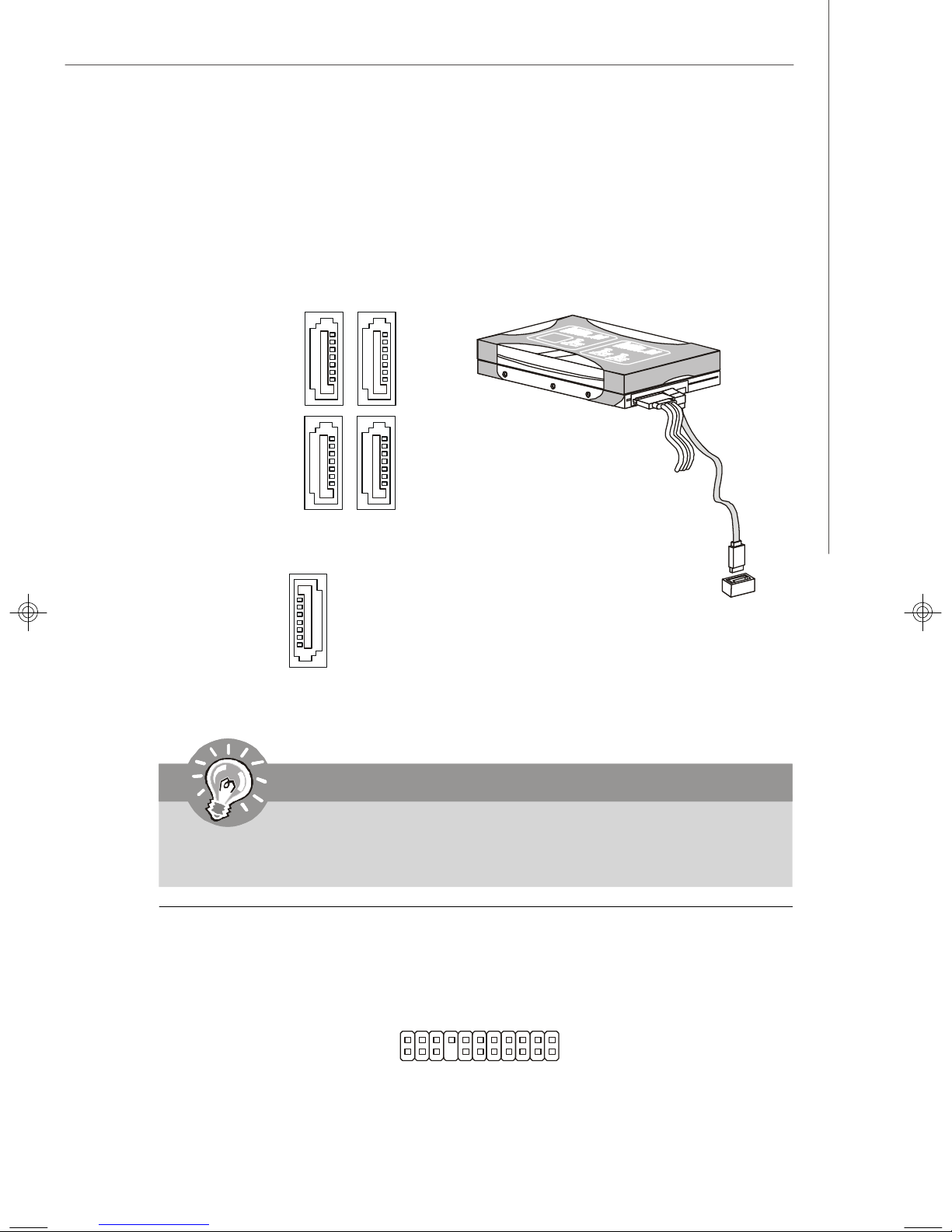
Serial ATA Connector: SATA3 ~ SATA7
This connector is a high-speed Serial ATA interface port. Each connector can connect
to one Serial ATA device.
SATA4
(optional)
SATA3
(optional)
SATA5SATA6
supported by Intel ICH9
SATA7
supported by Marvell 88SE6111
Important
Please do not fold the Serial ATA cable into 90-degree angle. Otherwise,
data loss may occur during transmission.
VoIP Card Connector: JSLIC1 (Only for ALC888T)
This connector connects to the VoIP card. Please refer to the instruction of the VoIP
card.
2
1
JSLIC1
22
21
2-13
MS-7345 Mainboard
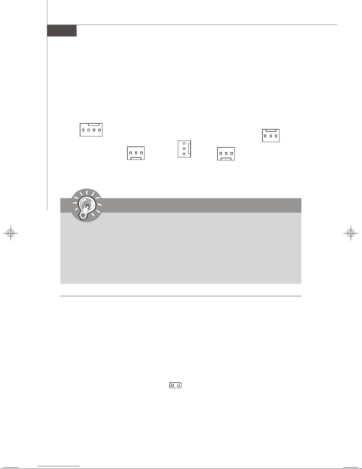
Fan Power Connectors: CPUFAN, SYSFAN1~5
The fan power connectors support system cooling fan with +12V. When connecting
the wire to the connectors, always note that the red wire is the positive and should
be connected to the +12V; the black wire is Ground and should be connected to GND.
If the mainboard has a System Hardware Monitor chipset on-board, you must use a
specially designed fan with speed sensor to take advantage of the CPU fan control.
GND
+12V
SENSOR
CONTROL
CPUFAN
+1 2V
GND
SYSFAN1
SENSOR
SE NS OR
+12V
GND
SYSFAN2
+1 2V
SE NSOR
GND
SYSFAN3/4
+1 2V
GND
SE NS OR
SYSFAN5
Important
1.Please refer to the recommended CPU fans at processor’s official website
or consult the vendors for proper CPU cooling fan.
2.CPUFAN supports fan control. You can install Dual Core Center utility that
will automatically control the CPU fan speed according to the actual CPU
temperature.
3. Fan cooler set with 3 or 4 pins power connector are both available for
CPUFAN.
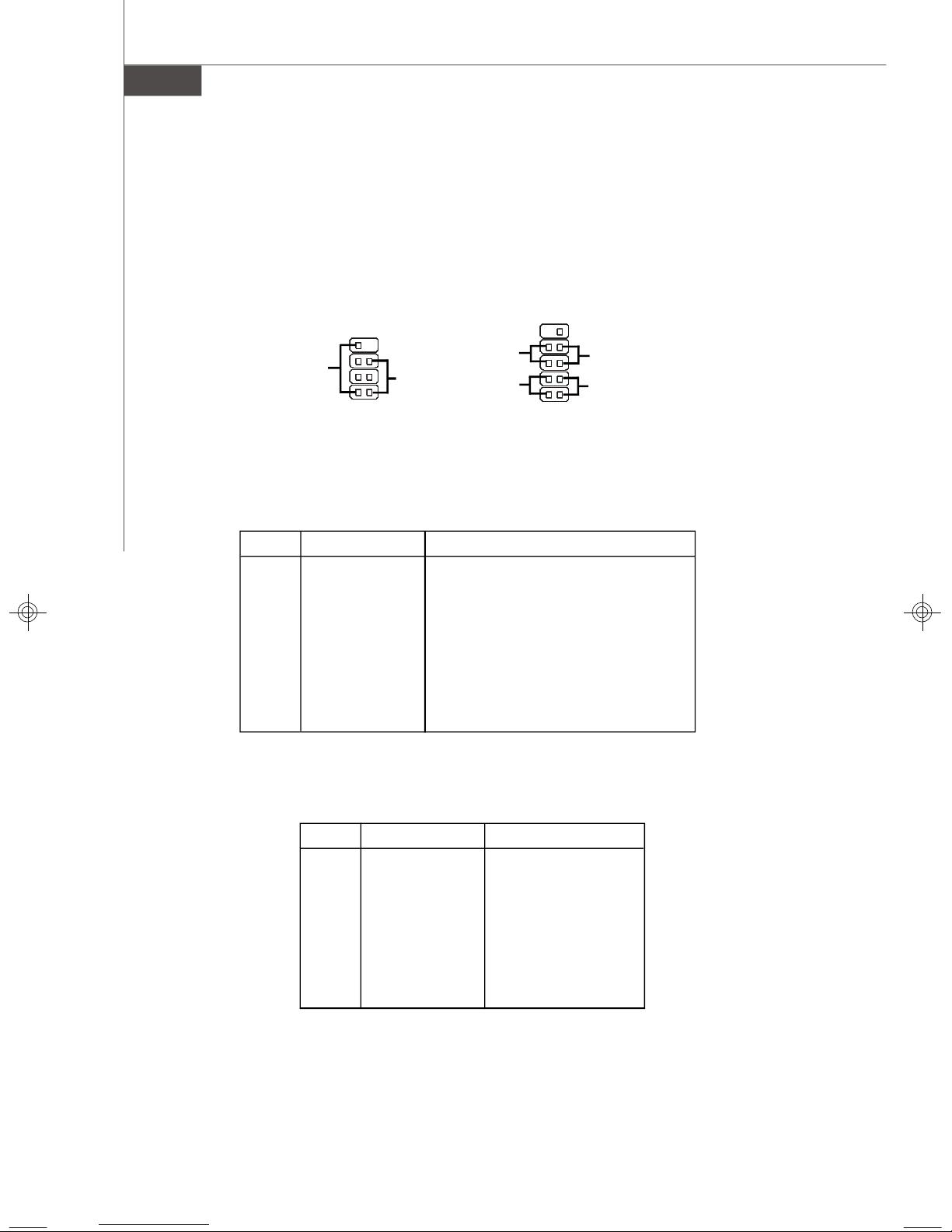
Chassis Intrusion Connector: JCI1
This connector connects to the chassis intrusion switch cable. If the chassis is
opened, the chassis intrusion mechanism will be activated. The system will record
this status and show a warning message on the screen. To clear the warning, you
must enter the BIOS utility and clear the record.
2-14
2
C
I
N
G
T
N
R
D
U
JCI1
1
Hardware Setup
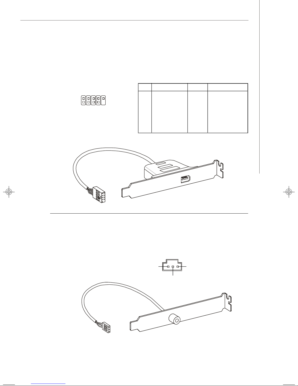
IEEE1394 Connector: J1394_1(Optional)
This connector allows you to connect the IEEE1394 device via an optional IEEE1394
bracket.
Pin Definition
PIN SIGNAL PIN SIGNAL
2
1
10
9
J1394_1
1 TPA+ 2 TPA3 Ground 4 Ground
5 TPB+ 6 TPB7 Cable power 8 Cable power
9 Key (no pin) 10 Ground
IEEE1394 Bracket (Optional)
S/PDIF-Out Connector: SPDO
This connector is used to connect S/PDIF (Sony & Philips Digital Interconnect Format)
interface for digital audio transmission.
SPDO
VCC
SPDIF
GND
S/PDIF Bracket (Optional)
2-15
MS-7345 Mainboard
Front Panel Connectors: JFP1, JFP2
These connectors are for electrical connection to the front panel switches and LEDs.
The JFP1 is compliant with Intel® Front Panel I/O Connectivity Design Guide.
10
-
2
JFP1
9
1
+
Reset
-
Switch
-
HDD
LED
Speaker
+
-
JFP2
8
+
2
7
Power
LED
1
Power
Switch++
Power
LED
JFP1 Pin Definition
PIN SIGNAL DESCRIPTION
1 HD_LED + Hard disk LED pull-up
2 FP PWR/SLP MSG LED pull-up
3 HD_LED - Hard disk active LED
4 FP PWR/SLP MSG LED pull-up
5 RST_SW - Reset Switch low reference pull-down to GND
6 PWR_SW + Power Switch high reference pull-up
7 RST_SW + Reset Switch high reference pull-up
8 PWR_SW - Power Switch low reference pull-down to GND
9 RSVD_DNU Reserved. Do not use.
PIN SIGNAL DESCRIPTION
1 GND Ground
2 SPK- Speaker3 SLED Suspend LED
4 BUZ+ Buzzer+
5 PLED Power LED
6 BUZ- Buzzer7 NC No connection
8 SPK+ Speaker+
2-16
JFP2 Pin Definition
 Loading...