

Page 1
MS-96E0
(v1.X) Server Board
G52-96E01X1
i
Page 2
Preface
MS-96E0
▍
Copyright Notice
The material in this document is the intellectual property of MICRO-STAR INTERNATIONAL. We take every care in the preparation of this document, but no guarantee is given as to the correctness of its contents. Our products are under continual improvement and we reserve the right to make changes without notice.
Trademarks
All trademarks are the properties of their respective owners.
MSI® is registered trademark of Micro-Star Int’l Co.,Ltd.
■
NVIDIA® is registered trademark of NVIDIA Corporation.
■
ATI® is registered trademark of ATI Technologies, Inc.
■
AMD® is registered trademarks of AMD Corporation.
■
Intel® is registered trademarks of Intel Corporation.
■
Windows
■
AMI® is registered trademark of Advanced Micro Devices, Inc.
■
Award® is a registered trademark of Phoenix Technologies Ltd.
■
Sound Blaster® is registered trademark of Creative Technology Ltd.
■
Realtek® is registered trademark of Realtek Semiconductor Corporation.
■
JMicron
■
Netware® is a registered trademark of Novell, Inc.
■
®
is registered trademarks of Microsoft Corporation.
®
is registered trademark of JMicron Technology Corporation.
Revision History
Revision Revision History Date
V1.0 First release February 2010
Technical Support
If a problem arises with your system and no solution can be obtained from the
user’s manual, please contact your place of purchase or local distributor. Alternatively, please try the following help resources for further guidance.
◙
Visit the MSI website for FAQ, technical guide, BIOS updates,
driver updates, and other information: http://www.msi.com/index.
php?func=service
◙
Contact our technical staff at: http://ocss.msi.com
ii
Page 3
MS-96E0
Safety Instructions
Always read the safety instructions carefully.
■
Keep this User’s Manual for future reference.
■
Keep this equipment away from humidity.
■
Lay this equipment on a reliable at surface before setting it up.
■
The openings on the enclosure are for air convection hence protects the
■
equipment from overheating. DO NOT COVER THE OPENINGS.
Make sure the voltage of the power source and adjust properly 110/220V
■
before connecting the equipment to the power inlet.
Place the power cord such a way that people can not step on it. Do not place
■
anything over the power cord.
Always Unplug the Power Cord before inserting any add-on card or mod
■
ule.
All cautions and warnings on the equipment should be noted.
■
Never pour any liquid into the opening that could damage or cause electrical
■
shock.
If any of the following situations arises, get the equipment checked by ser
■
vice personnel:
The power cord or plug is damaged.
◯
Liquid has penetrated into the equipment.
◯
The equipment has been exposed to moisture.
◯
The equipment does not work well or you can not get it work according
◯
to User’s Manual.
The equipment has dropped and damaged.
◯
The equipment has obvious sign of breakage.
◯
DO NOT LEAVE THIS EQUIPMENT IN AN ENVIRONMENT UNCONDI-
■
TIONED, STORAGE TEMPERATURE ABOVE 60oC (140oF), IT MAY DAMAGE THE EQUIPMENT.
MS-96E0
-
-
CAUTION: Danger of explosion if battery is incorrectly replaced. Replace only
with the same or equivalent type recommended by the manufacturer.
警告使用者:
這是甲類資訊產品,在居住的環境中使用時,可能會造成無線電干擾,在這種情
況下,使用者會被要求採取某些適當的對策。
廢電池請回收
For better environmental protection, waste batteries should be col
lected separately for recycling special disposal.
iii
-
Page 4
Preface
MS-96E0
▍
FCC-B Radio Frequency Interference Statement
This equipment has been tested and
found to comply with the limits for a
Class B digital device, pursuant to Part
15 of the FCC Rules. These limits are
designed to provide reasonable protection against harmful interference in a residential installation. This equipment
generates, uses and can radiate radio frequency energy and, if not installed and
used in accordance with the instructions, may cause harmful interference to radio
communications. However, there is no guarantee that interference will not occur
in a particular installation. If this equipment does cause harmful interference to
radio or television reception, which can be determined by turning the equipment
off and on, the user is encouraged to try to correct the interference by one or more
of the measures listed below.
Reorient or relocate the receiving antenna.
◯
Increase the separation between the equipment and receiver.
◯
Connect the equipment into an outlet on a circuit different from that to
◯
which the receiver is connected.
Consult the dealer or an experienced radio/television technician for help.
◯
Notice 1
The changes or modications not expressly approved by the party responsible for
compliance could void the user’s authority to operate the equipment.
Notice 2
Shielded interface cables and A.C. power cord, if any, must be used in order to
comply with the emission limits.
VOIR LA NOTICE D’INSTALLATION AVANT DE RACCORDER AU RESEAU.
Micro-Star International
MS-96E0
This device complies with Part 15 of the FCC Rules. Operation is subject to the
following two conditions:
this device may not cause harmful interference, and
1)
this device must accept any interference received, including interference that
2)
may cause undesired operation.
iv
Page 5
MS-96E0
MS-96E0
WEEE Statement
ENGLISH
To protect the global environment and as an environmentalist, MSI must
remind you that...
Under the European Union (“EU”) Directive on Waste Electrical and
Electronic Equipment, Directive 2002/96/EC, which takes effect on Au
gust 13, 2005, products of “electrical and electronic equipment” cannot
be discarded as municipal waste anymore and manufacturers of covered electronic
equipment will be obligated to take back such products at the end of their useful life.
MSI will comply with the product take back requirements at the end of life of MSIbranded products that are sold into the EU. You can return these products to local
collection points.
DEUTSCH
Hinweis von MSI zur Erhaltung und Schutz unserer Umwelt
Gemäß der Richtlinie 2002/96/EG über Elektro- und Elektronik-Altgeräte dürfen
Elektro- und Elektronik-Altgeräte nicht mehr als kommunale Abfälle entsorgt werden.
MSI hat europaweit verschiedene Sammel- und Recyclingunternehmen beauftragt,
die in die Europäische Union in Verkehr gebrachten Produkte, am Ende seines Leb
enszyklus zurückzunehmen. Bitte entsorgen Sie dieses Produkt zum gegebenen
Zeitpunkt ausschliesslich an einer lokalen Altgerätesammelstelle in Ihrer Nähe.
FRANÇAIS
En tant qu’écologiste et an de protéger l’environnement, MSI tient à rappeler
ceci...
Au sujet de la directive européenne (EU) relative aux déchets des équipement élec
triques et électroniques, directive 2002/96/EC, prenant effet le 13 août 2005, que les
produits électriques et électroniques ne peuvent être déposés dans les décharges
ou tout simplement mis à la poubelle. Les fabricants de ces équipements seront
obligés de récupérer certains produits en n de vie. MSI prendra en compte cette
exigence relative au retour des produits en n de vie au sein de la communauté
européenne. Par conséquent vous pouvez retourner localement ces matériels dans
les points de collecte.
-
-
-
РУССКИЙ
Компания MSI предпринимает активные действия по защите окружающей
среды, поэтому напоминаем вам, что....
В соответствии с директивой Европейского Союза (ЕС) по предотвращению
загрязнения окружающей среды использованным электрическим и электронным
оборудованием (директива WEEE 2002/96/EC), вступающей в силу 13
августа 2005 года, изделия, относящиеся к электрическому и электронному
оборудованию, не могут рассматриваться как бытовой мусор, поэтому
производители вышеперечисленного электронного оборудования обязаны
принимать его для переработки по окончании срока службы. MSI обязуется
соблюдать требования по приему продукции, проданной под маркой MSI на
территории EC, в переработку по окончании срока службы. Вы можете вернуть
эти изделия в специализированные пункты приема.
v
Page 6

Preface
MS-96E0
▍
ESPAÑOL
MSI como empresa comprometida con la protección del medio ambiente, recomienda:
Bajo la directiva 2002/96/EC de la Unión Europea en materia de desechos y/o equi
pos electrónicos, con fecha de rigor desde el 13 de agosto de 2005, los productos
clasicados como “eléctricos y equipos electrónicos” no pueden ser depositados en
los contenedores habituales de su municipio, los fabricantes de equipos electrónicos, están obligados a hacerse cargo de dichos productos al termino de su período
de vida. MSI estará comprometido con los términos de recogida de sus productos
vendidos en la Unión Europea al nal de su periodo de vida. Usted debe depositar
estos productos en el punto limpio establecido por el ayuntamiento de su localidad o
entregar a una empresa autorizada para la recogida de estos residuos.
NEDERLANDS
Om het milieu te beschermen, wil MSI u eraan herinneren dat….
De richtlijn van de Europese Unie (EU) met betrekking tot Vervuiling van Electrische
en Electronische producten (2002/96/EC), die op 13 Augustus 2005 in zal gaan kun
nen niet meer beschouwd worden als vervuiling. Fabrikanten van dit soort producten
worden verplicht om producten retour te nemen aan het eind van hun levenscyclus.
MSI zal overeenkomstig de richtlijn handelen voor de producten die de merknaam
MSI dragen en verkocht zijn in de EU. Deze goederen kunnen geretourneerd worden op lokale inzamelingspunten.
SRPSKI
Da bi zaštitili prirodnu sredinu, i kao preduzeće koje vodi računa o okolini i prirodnoj
sredini, MSI mora da vas podesti da…
Po Direktivi Evropske unije (“EU”) o odbačenoj ekektronskoj i električnoj opremi, Di-
rektiva 2002/96/EC, koja stupa na snagu od 13. Avgusta 2005, proizvodi koji spadaju
pod “elektronsku i električnu opremu” ne mogu više biti odbačeni kao običan otpad
i proizvođači ove opreme biće prinuđeni da uzmu natrag ove proizvode na kraju
njihovog uobičajenog veka trajanja. MSI će poštovati zahtev o preuzimanju ovakvih
proizvoda kojima je istekao vek trajanja, koji imaju MSI oznaku i koji su prodati u EU.
Ove proizvode možete vratiti na lokalnim mestima za prikupljanje.
-
-
POLSKI
Aby chronić nasze środowisko naturalne oraz jako rma dbająca o ekologię, MSI
przypomina, że...
Zgodnie z Dyrektywą Unii Europejskiej (“UE”) dotyczącą odpadów produktów elektrycznych i elektronicznych (Dyrektywa 2002/96/EC), która wchodzi w życie 13 sierpnia 2005, tzw. “produkty oraz wyposażenie elektryczne i elektroniczne “ nie mogą
być traktowane jako śmieci komunalne, tak więc producenci tych produktów będą
zobowiązani do odbierania ich w momencie gdy produkt jest wycofywany z użycia.
MSI wypełni wymagania UE, przyjmując produkty (sprzedawane na terenie Unii Europejskiej) wycofywane z użycia. Produkty MSI będzie można zwracać w wyznac-
zonych punktach zbiorczych.
vi
Page 7

MS-96E0
MS-96E0
TÜRKÇE
Çevreci özelliğiyle bilinen MSI dünyada çevreyi korumak için hatırlatır:
Avrupa Birliği (AB) Kararnamesi Elektrik ve Elektronik Malzeme Atığı, 2002/96/EC
Kararnamesi altında 13 Ağustos 2005 tarihinden itibaren geçerli olmak üzere, elektrikli ve elektronik malzemeler diğer atıklar gibi çöpe atılamayacak ve bu elektonik
cihazların üreticileri, cihazların kullanım süreleri bittikten sonra ürünleri geri toplamakla yükümlü olacaktır. Avrupa Birliği’ne satılan MSI markalı ürünlerin kullanım
süreleri bittiğinde MSI ürünlerin geri alınması isteği ile işbirliği içerisinde olacaktır.
Ürünlerinizi yerel toplama noktalarına bırakabilirsiniz.
ČESKY
Záleží nám na ochraně životního prostředí - společnost MSI upozorňuje...
Podle směrnice Evropské unie (“EU”) o likvidaci elektrických a elektronických
výrobků 2002/96/EC platné od 13. srpna 2005 je zakázáno likvidovat “elektrické
a elektronické výrobky” v běžném komunálním odpadu a výrobci elektronických
výrobků, na které se tato směrnice vztahuje, budou povinni odebírat takové výrobky
zpět po skončení jejich životnosti. Společnost MSI splní požadavky na odebírání
výrobků značky MSI, prodávaných v zemích EU, po skončení jejich životnosti. Tyto
výrobky můžete odevzdat v místních sběrnách.
MAGYAR
Annak érdekében, hogy környezetünket megvédjük, illetve környezetvédőként fellépve az MSI emlékezteti Önt, hogy ...
Az Európai Unió („EU”) 2005. augusztus 13-án hatályba lépő, az elektromos és elektronikus berendezések hulladékairól szóló 2002/96/EK irányelve szerint az elektro-
mos és elektronikus berendezések többé nem kezelhetőek lakossági hulladékként,
és az ilyen elektronikus berendezések gyártói kötelessé válnak az ilyen termékek
visszavételére azok hasznos élettartama végén. Az MSI betartja a termékvisszavétellel kapcsolatos követelményeket az MSI márkanév alatt az EU-n belül értékesített
termékek esetében, azok élettartamának végén. Az ilyen termékeket a legközelebbi
gyűjtőhelyre viheti.
ITALIANO
Per proteggere l’ambiente, MSI, da sempre amica della natura, ti ricorda che….
In base alla Direttiva dell’Unione Europea (EU) sullo Smaltimento dei Materiali
Elettrici ed Elettronici, Direttiva 2002/96/EC in vigore dal 13 Agosto 2005, prodotti
appartenenti alla categoria dei Materiali Elettrici ed Elettronici non possono più es
sere eliminati come riuti municipali: i produttori di detti materiali saranno obbligati
a ritirare ogni prodotto alla ne del suo ciclo di vita. MSI si adeguerà a tale Direttiva
ritirando tutti i prodotti marchiati MSI che sono stati venduti all’interno dell’Unione
Europea alla ne del loro ciclo di vita. È possibile portare i prodotti nel più vicino
punto di raccolta.
vii
-
Page 8

Preface
▍
TABLE OF CONTENTS
▍
Copyright Notice �����������������������������������������������������������������������������������ii
Trademarks ������������������������������������������������������������������������������������������� ii
Revision History ����������������������������������������������������������������������������������� ii
Technical Support ��������������������������������������������������������������������������������ii
Safety Instructions ������������������������������������������������������������������������������ iii
FCC-B Radio Frequency Interference Statement ����������������������������� iv
WEEE Statement�����������������������������������������������������������������������������������v
Chapter 1 Overview ���������������������������������������������������������������������������1-1
Mainboard Specications ............................................................................ 1-2
Mainboard Layout
.......................................................................................1-4
Chapter 2 Hardware Setup����������������������������������������������������������������2-1
Quick Components Guide ........................................................................... 2-2
CPU (Central Processing Unit)
Memory ....................................................................................................... 2-6
Power Supply .............................................................................................. 2-8
Rear Panel I/O ............................................................................................2-9
Connector .................................................................................................. 2-10
Jumper ...................................................................................................... 2-16
Slot ............................................................................................................ 2-18
...................................................................2-3
Chapter 3 BIOS Setup �����������������������������������������������������������������������3-1
Entering Setup ............................................................................................3-2
The Menu Bar .............................................................................................3-4
Main
............................................................................................................3-5
Advanced .................................................................................................... 3-6
Boot ...........................................................................................................3-17
Security
..................................................................................................... 3-19
Chipset
...................................................................................................... 3-20
Exit
............................................................................................................ 3-23
Appendix A Intel ICH10R SATA RAID ���������������������������������������������� A-1
Introduction .................................................................................................A-2
BIOS Conguration .....................................................................................A-3
Installing Driver
Installing Software
RAID Migration Instructions
.........................................................................................A-10
.....................................................................................A-12
......................................................................A-16
viii
Page 9

MS-96E0
Recovery Volume Creation ......................................................................A-23
Degraded RAID Array ..............................................................................A-27
Appendix B LSI SAS RAID (Optional) �������������������������������������������� B-1
1. Introduction to Integrated RAID ..............................................................B-2
2. Integrated Mirroring Overview
3. Creating Integrated Mirroring Volumes
4. Integrated Striping Overview
5. Creating Integrated Striping Volumes
................................................................B-3
..................................................B-9
................................................................B-16
..................................................B-19
Appendix C LCM Front Panel Control (Optional) ������������������������� C-1
The LCM Control Utility ..............................................................................C-2
LCM Function Menu
...................................................................................C-7
Page 10

Page 11

Chapter 1
Overview
Thank you for choosing the MS-96E0 v1.X, an excellent
server board from MSI.
Based on the innovative Intel
for optimal system efciency, the MS-96E0 accommodates the latest Intel® Nehalem and Westmere processors (up to 130W) in LGA1366 package and supports
up to 6 DDR3 800/1066/1333 DIMM slots to provide the
maximum of 96GB memory capacity.
In the advanced-level and mid-range market segment,
the MS-96E0 can provide a high-performance solution
for today’s front-end and general purpose server, as well
as in the future.
®
5500 & ICH10R chipsets
1-1-1
Page 12

Overview
MS-96E0
▍
Mainboard SpecificationS
Processor
Intel Nehalem & Westmere processors (up to 130W) in LGA1366 package
■
Supported QPI
Up to 6.4 GT/s
■
Chipset
North Bridge: Intel 5500 chipset
■
South Bridge: Intel ICH10R chipset
■
Memory
6 DDR3 800/1066/1333 DIMM slots (240pin / 1.5V)
■
Supports the maximum of 96GB Registered DIMM or 48GB Unbuffered DIMM
■
System Management
Aspeed AST1100 BMC controller with IPMI 2.0 compliance
■
LAN
Supports Gigabit LAN by Intel 82574L Gb Ethernet controller (JLAN1 for IPMI)
■
SATA
6 SATA 3Gb/s ports by Intel ICH10R
■
SAS (Optional)
Optionally supported through MS-95X4 SAS card:
■
Option 1: 8 mini SAS ports by LSI Logic SAS1068E Host Controller with
-
RAID0, 1, 10 and optional RAID5 with i-Button
Option 2: 4 mini SAS ports by LSI Logic SAS1064E Host Controller with
-
RAID0, 1, 10 and optional RAID5 with i-Button
Data transfer rate at up to 3Gb/s
■
IDE
1 IDE port by ITE IT8213F
■
Supports Ultra DMA 66/100/133 mode
■
Supports PIO, Bus Master operation mode
■
LCM (Optional)
LCM panel is optionally supported in the following operating systems:
■
Windows: 2000/ XP/ 2003 32/64 bits
-
Linux: RedHat/ SuSE/ Fedora kernel >= 2.6
-
Graphics
Aspeed AST1100 graphics controller
■
1-2
Page 13

MS-96E0
Onboard Input/Output
Back Panel
■
1 PS/2 mouse port
-
1 PS/2 keyboard port
-
2 USB 2.0 ports
-
1 serial port
-
1 D-Sub VGA port
-
2 RJ-45 LAN jacks
-
Onboard Connectors
■
2 USB 2.0 pinheaders (4 ports)
-
1 serial port connector
-
1 SMBus connector
-
1 SPI Flash ROM pinheader (for debugging)
-
1 chassis intrusion connector
-
1 TPM connector
-
Slot
1 PCI Express 2.0 x16 slot
■
1 PCI-Express 2.0 x4 slot
■
1 PCI-Express 2.0 x4 slot (for LSI 1068E/1064 SAS Riser Card)
■
1 PCI-Express 1.0 x4 slot
■
1 32-bit/33MHz PCI slot
■
Dimension
12” x 10.2” SSI CEB form factor
■
Mounting
8 mounting holes
■
MS-96E0
1-3
Page 14

Overview
▍
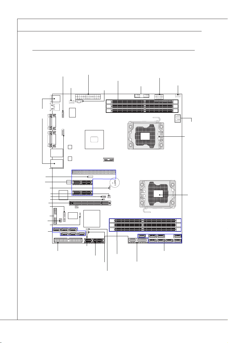
Mainboard Layout
1-4
Page 15

Chapter 2
Hardware Setup
This chapter provides you with the information about
hardware setup procedures. While doing the installation, be careful in holding the components and follow the
installation procedures. For some components, if you
install in the wrong orientation, the components will not
work properly.
Use a grounded wrist strap before handling computer
components. Static electricity may damage the compo
nents.
-
2-2-1
Page 16
Hardware Setup
MS-96E0
▍
Quick coMponentS Guide
Rear Panel
I/O, p. 2-9
COM2, p. 2-13
JIPMB1, p. 2-14
PCI Express
Slots, p. 2-18
CLR_CMOS, p. 2-17
INTRUDER, p. 2-14
J2, p. 2-14
JBIOS_WP, p. 2-16
PCI Slot, p. 2-18
JFRONT1, p. 2-12
JUSB2~3, p. 2-13
JSGPIO1, p. 2-12
RECOVERY, p. 2-16
SATA0~5, p. 2-10
JTPM1, p. 2-15
SY S_FA N4,
p. 2-11
JPWR2, p. 2-8
JSMBU S2 ,
p. 2-14
DIMM Slots, p. 2-6
SYS_FAN1/2, p. 2-11
JPWR1, p. 2-8
SYS_FAN3, p. 2-11
CPU0 /1_FAN,
p. 2-11
CPU, p. 2-3
CPU, p. 2-3
2-2
JIDE1, p. 2-11
JSASID1, p. 2-17
PCI Express Slot, p. 2-18
JLCD1, p. 2-15
JGPIO33, p. 2-12
DIMM Slots,
p. 2-6
PCI Express Slot,
p. 2-18
SAS_1~8, p. 2-10
Page 17
MS-96E0
MS-96E0
cpu (centraL proceSSinG unit)
When you are installing the CPU, make sure that you install the cooler to prevent
overheating. If you do not have the CPU cooler, consult your dealer before turn-
ing on the computer.
Important
Overheating
Overheating will seriously damage the CPU and system. Always make sure the
cooling fan can work properly to protect the CPU from overheating. Make sure
that you apply an even layer of thermal paste (or thermal tape) between the CPU
and the heatsink to enhance heat dissipation.
Replacing the CPU
While replacing the CPU, always turn off the power supply or unplug the power
supply’s power cord from the grounded outlet rst to ensure the safety of CPU.
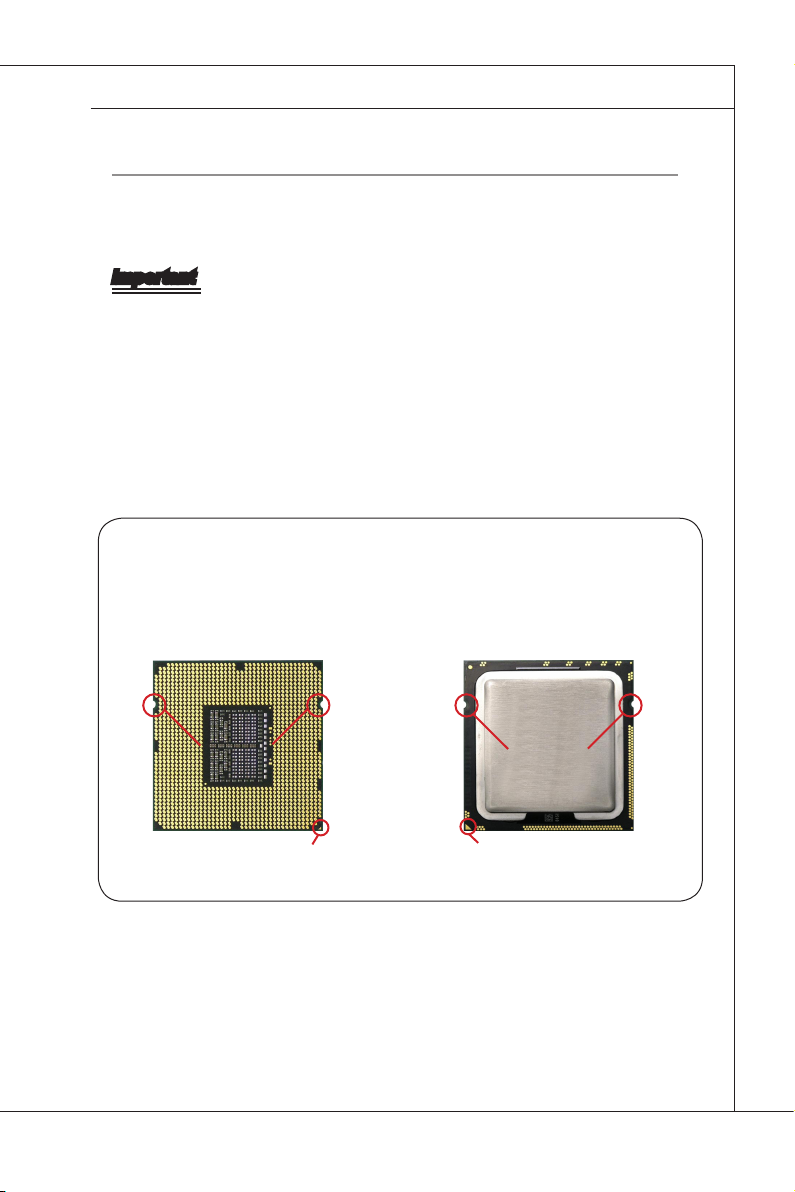
Introduction to LGA 1366 CPU
The pin-pad side of LGA 1366 CPU. The surface of LGA 1366 CPU. Re-
member to apply some thermal paste
on it for better heat dispersion.
Alignment Key
Yellow triangle is the Pin 1 indicator
Alignment Key
Yellow triangle is the Pin 1 indicator
2-3
Page 18
Hardware Setup
MS-96E0
▍
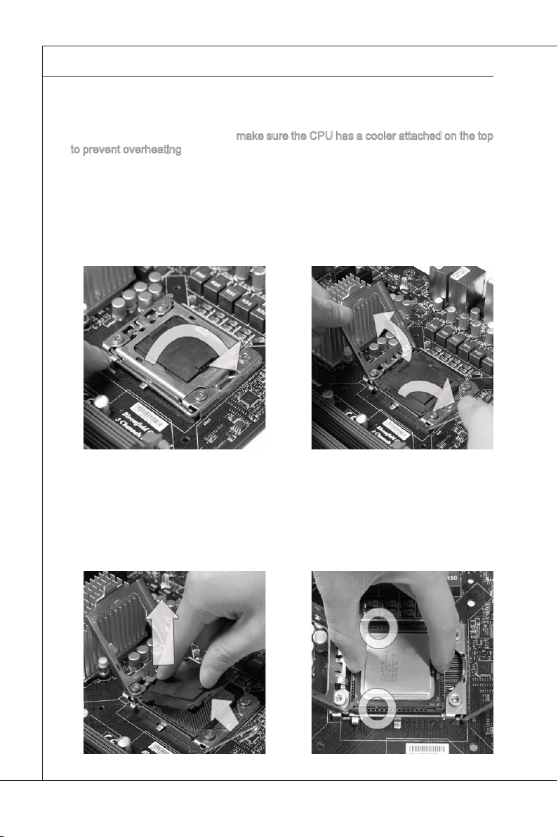
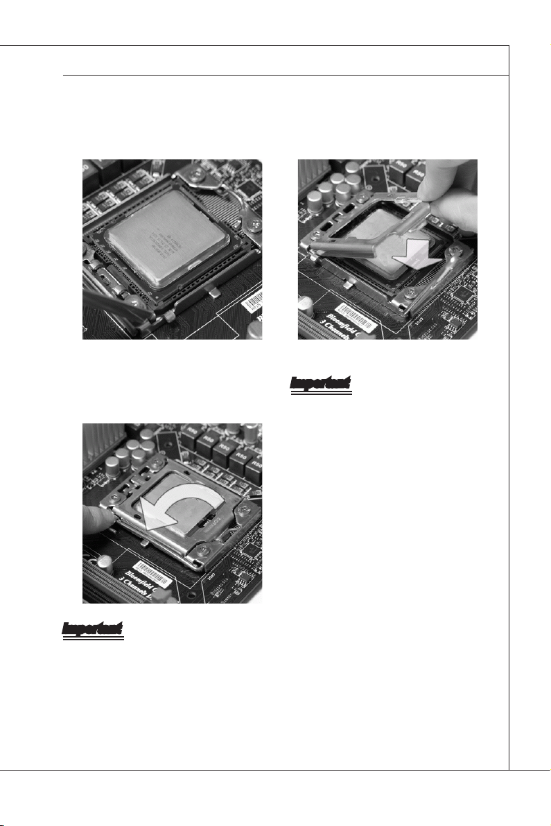
CPU Installation
When you are installing the CPU, make sure the CPU has a cooler attached on the top
to prevent overheating. Meanwhile, do not forget to apply some thermal paste on CPU
before installing the heat sink/cooler fan for better heat dispersion.
Follow the steps below to install the CPU correctly. Wrong installation will cause the
damage of your CPU & mainboard.
Open the load lever.
1.
Lift the load lever up and open the
2.
load plate.
The CPU socket has a plastic cap
3. After conrming the CPU direction
on it to protect the contact from
damage. Before you install CPU,
always cover it to protect the
socket pin. Remove the cap from
the lever hinge side.
4.
for correct mating, put down the
CPU in the socket housing frame.
Be sure to grasp on the edge of the
CPU base. Note that the alignment
keys are matched.
Alignment Key
2-4
Page 19
MS-96E0
MS-96E0
Visually inspect if the CPU is seated
5. Cover the load plate onto the packwell into the socket. If not, take out
the CPU with pure vertical motion
and reinstall.
Press down the load lever lightly onto
7.
the load plate, and then secure the
lever with the hook under the retention tab.
6.
age.
Important
Conrm if your CPU cooler is rmly in-
•
stalled before turning on your system.
Do not touch the CPU socket pins to
•
avoid damage.
Important
Read the CPU status in BIOS.
•
Whenever CPU is not installed, always protect your CPU socket pin with the plastic
•
cap covered (shown in Figure 1) to avoid damage.
Mainboard photos shown in this section are for demonstration of the CPU installa-
•
tion only. The appearance of your mainboard may vary depending on the model you
purchased.
Please refer to the documentation in the CPU fan package for more details about the
•
CPU fan installation.
2-5
Page 20
Hardware Setup
MS-96E0
▍
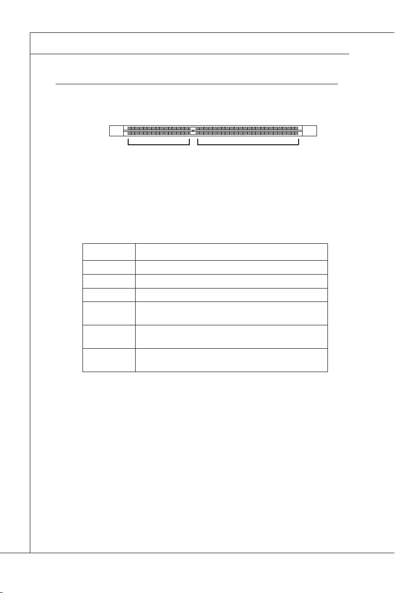
MeMory
These DIMM slots are intended for memory modules.
DDR3
240-pin, 1�5V
48x2=96 pin
72x2=144 pin
Memory Population Rules
In Multi-Channel mode, make sure that you install memory modules of the same
type and density in different channel DIMM slots.
Population Rules
1 DIMM CPU0_DIMM1
2 DIMMs CPU0_DIMM1 + CPU1_DIMM1
3 DIMMs CPU0_DIMM1 + CPU1_DIMM1 + CPU0_DIMM2
4 DIMMs CPU0_DIMM1 + CPU1_DIMM1 + CPU0_DIMM2 +
5 DIMMs CPU0_DIMM1 + CPU1_DIMM1 + CPU0_DIMM2 +
6 DIMMs CPU0_DIMM1 + CPU1_DIMM1 + CPU0_DIMM2 +
CPU1_DIMM2
CPU1_DIMM2 + CPU0_DIMM3
CPU1_DIMM2 + CPU0_DIMM3 + CPU1_DIMM3
2-6
Page 21
MS-96E0
MS-96E0
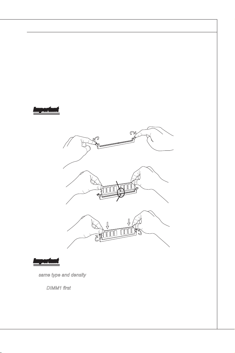
Installing Memory Modules
The memory module has only one notch on the center and will only t in the
1.
right orientation.
Insert the memory module vertically into the DIMM slot. Then push it in until
2.
the golden nger on the memory module is deeply inserted in the DIMM slot.
The plastic clip at each side of the DIMM slot will automatically close when
the memory module is properly seated.
Manually check if the memory module has been locked in place by the DIMM
3.
slot clips at the sides.
Important
You can barely see the golden nger if the memory module is properly inserted
in the DIMM slot.
Notch
Volt
Important
In Multi-Channel mode, make sure that you install memory modules of the
•
same type and density in different channel DIMM slots.
To enable successful system boot-up, always insert the memory modules into
•
the DIMM1 rst.
2-7
Page 22
Hardware Setup
MS-96E0
▍
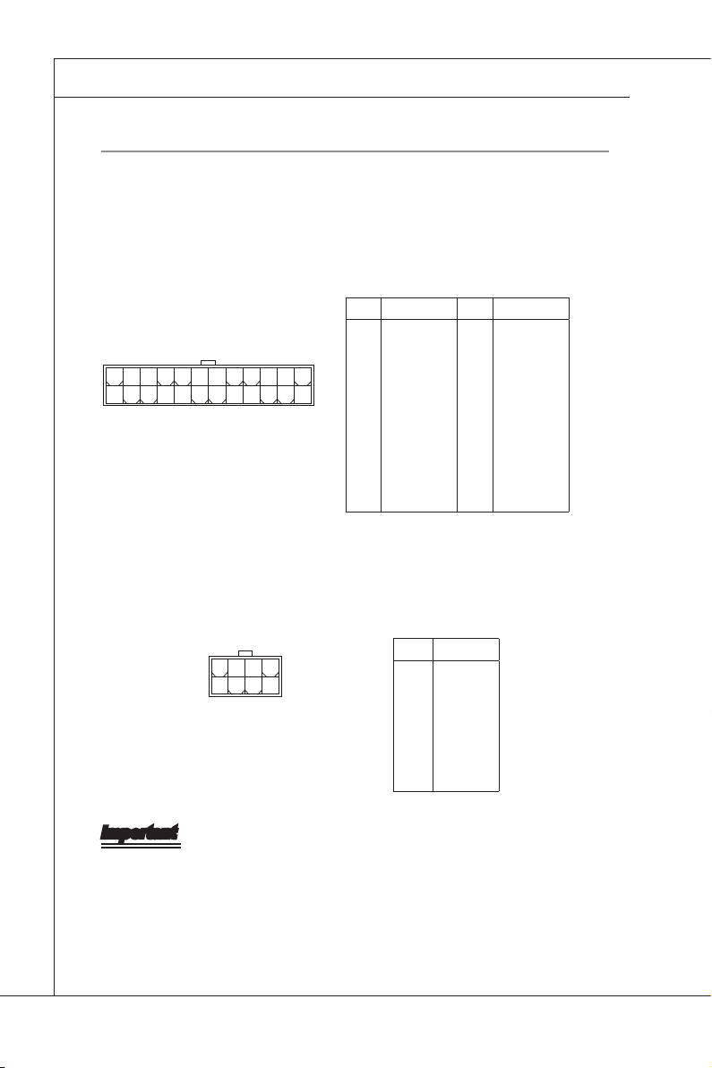
power SuppLy
System Power Connector: JPWR2
This connector allows you to connect a power supply. To connect to the power
supply, make sure the plug of the power supply is inserted in the proper orienta-
tion and the pins are aligned. Then push down the power supply rmly into the
connector.
PIN SIGNAL PIN SIGNAL
1
+3.3V
2
+3.3V
3
24
12
13
1
GND
4
+5V
5
GND
6
+5V
7
GND
8
PWR OK
9
5VSB
10
+12V
11
+12V
12
+3.3V
CPU/Memory Power Connector: JPWR1
This connector provides 12V power output to the CPUs & memory.
13
+3.3V
14
-12V
15
GND
16
PS-ON#
17
GND
18
GND
19
GND
20
+3.3VSB
21
+5V
22
+5V
23
+5V
24
GND
8
4
5
1
PIN SIGNAL
1
GND
2
GND
3
GND
4
GND
5
+12V
6
+12V
7
+12V
8
+12V
Important
Make sure that all power connectors are connected to the power supply to
•
ensure stable operation of the mainboard.
Power supply of 600 watts (and above) is highly recommended for system
•
stability.
2-8
Page 23
MS-96E0
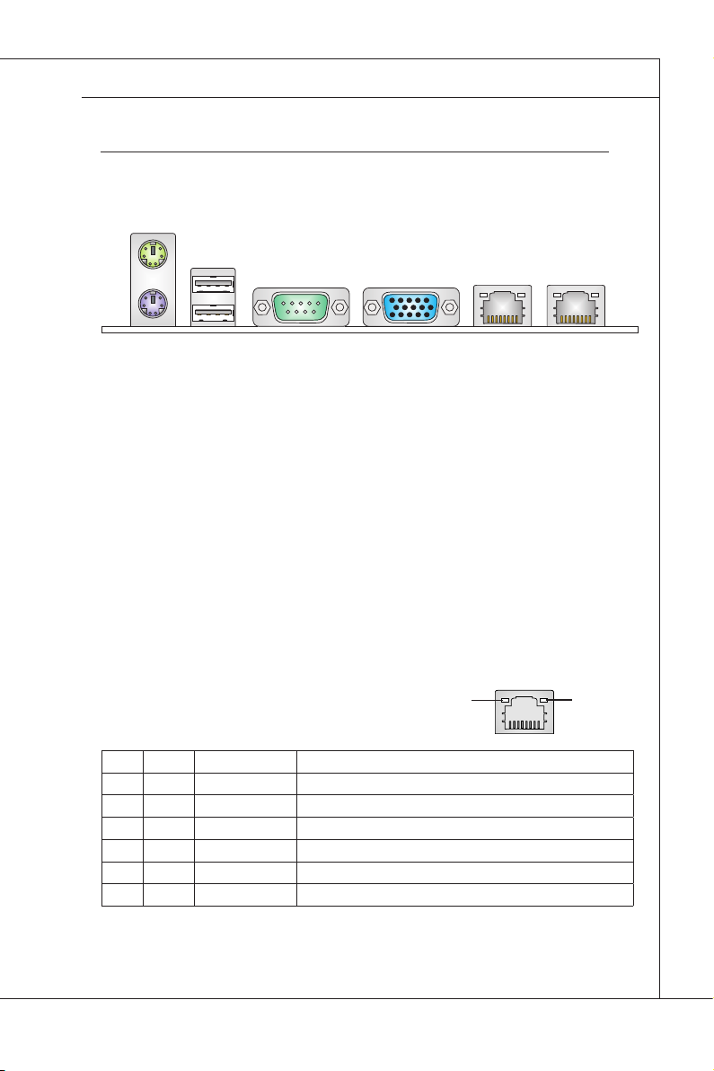
rear paneL i/o
Mouse Port
MS-96E0
Keyboard
Port
Mouse/Keyboard Port
▶
Serial Port LAN Jack LAN Jack
VGA PortUSB Port
The standard PS/2 mouse/keyboard DIN connector is for a PS/2 mouse/key
board.
USB Port
▶
The USB (Universal Serial Bus) port is for attaching USB devices such as key
board, mouse, or other USB-compatible devices.
Serial Port
▶
The serial port is a 16550A high speed communications port that sends/ receives
16 bytes FIFOs. You can attach a serial mouse or other serial devices directly to
the connector.
VGA Port
▶
The DB15-pin female connector is provided for monitor.
LAN
▶
The standard RJ-45 LAN jack is for connection to
Yellow Green/ Orange
the Local Area Network (LAN). You can connect a
network cable to it.
LED Color LED State Condition
Left Yellow Off LAN link is not established.
On (steady state) LAN link is established.
On (blinking) The computer is communicating with another computer on the LAN.
Right
Green Off 10 Mbit/sec data rate is selected.
On 100 Mbit/sec data rate is selected.
Orange On 1000 Mbit/sec data rate is selected.
-
-
2-9
Page 24
Hardware Setup
MS-96E0
▍
connector
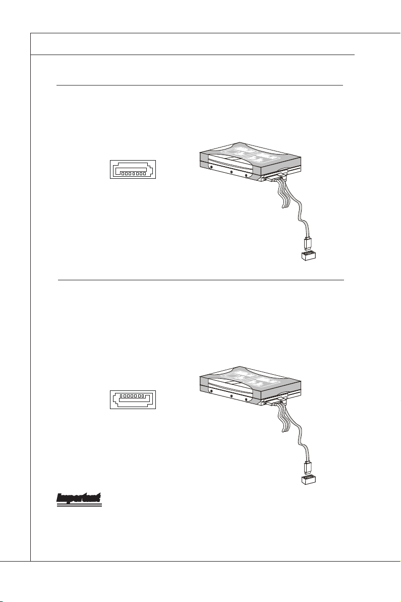
Serial ATA Connector: SATA0 ~ SATA5
This connector is a high-speed Serial ATA interface port. Each connector can
connect to one Serial ATA device.
Serial Attached SCSI Connector: SAS_1 ~ SAS_8
The SAS connector is a new generation serial communication protocol for devices designed to allow for much higher speed data transfers. It supports data
transfer speeds up to 3 Gbit/s. SAS uses serial communication instead of the parallel method found in traditional SCSI devices but still uses SCSI commands for
interacting with SAS devices. Each SAS connector can connect to 1 disk drive.
Important
Please do not fold the SATA/SAS cable into 90-degree angle. Otherwise, data
loss may occur during transmission.
2-10
Page 25
MS-96E0
MS-96E0
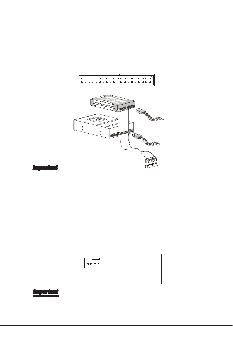
IDE Connector: JIDE1
This connector supports IDE hard disk drives, optical disk drives and other IDE
devices.
Important
If you install two IDE devices on the same cable, you must congure the drives
separately to master / slave mode by setting jumpers. Refer to IDE device’s documentation supplied by the vendors for jumper setting instructions.
Fan Power Connector: CPU0_FAN, CPU1_FAN, SYS_FAN1/2/3/4
The fan power connectors support system cooling fan with +12V. When connecting the wire to the connectors, always note that the red wire is the positive
and should be connected to the +12V; the black wire is Ground and should be
connected to GND. If the mainboard has a System Hardware Monitor chipset
onboard, you must use a specially designed fan with speed sensor to take advantage of the CPU fan control.
PIN SIGNAL
14
1
GND
2
+12V
3
Sensor
4
Control
Important
Please refer to the recommended CPU fans at processor ’s ofcial website or
consult the vendors for proper CPU cooling fan.
2-11
Page 26
Hardware Setup
MS-96E0
▍
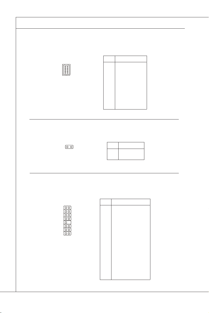
SGPIO Connector: JSGPIO1
This connector is used to support serial-link interface for the onboard SATA connectors.
PIN SIGNAL
NC
10
9
2
1
1
2
3
4
5
6
7
8
9
10
ICH_SDATAOUT0
NC
ICH_SDATAOUT1
NC
ICH_SCLOAD
NC
ICH_SCLOCK
GND
GND
GPIO Connector: JGPIO33
This connector is provided for factory use only.
1
PIN SIGNAL
12GPIO33
GND
Front Panel Connector: JFRONT1
The mainboard provides one front panel connector for electrical connection to the
front panel switches and LEDs.
PIN SIGNAL
21
16
15
HDD LED+
1
POWER LED+
2
HDD LED-
3
POWER LED-
4
SYS RST SWITCH+
5
POWER SWITCH+
6
SYS RST SWITCH-
7
POWER SWITCH-
8
NC
9
KEY
10
SYS LED+
11
SYS LED-
12
LAN2 ACT LED+
13
LAN2 ACT LED-
14
LAN1 ACT LED+
15
LAN1 ACT LED-
16
2-12
Page 27
MS-96E0
MS-96E0
Serial Port Connector: COM2
This connector is a 16550A high speed communications port that sends/receives
16 bytes FIFOs. You can attach a serial device to it through the optional serial
port bracket.
PIN SIGNAL DESCRIPTION
910
12
1
DCD
2
SIN
3
SOUT
4
DTR
5
GND
6
DSR
7
RTS
8
CTS
9
RI
Data Carry Detect
Serial In or Receive Data
Serial Out or Transmit Data
Data Terminal Ready
Ground
Data Set Ready
Request To Send
Clear To Send
Ring Indicate
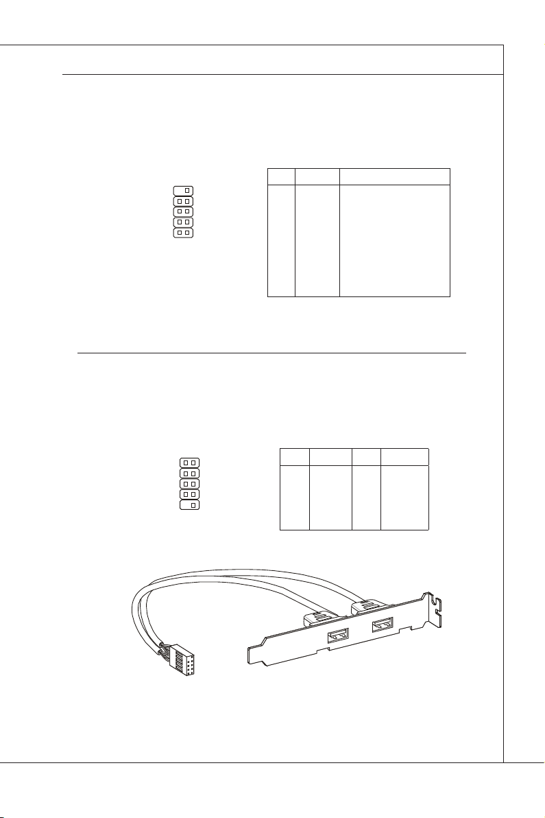
Front USB Connector: JUSB2, JUSB3
This connector, compliant with Intel I/O Connectivity Design Guide, is ideal for
connecting high-speed USB interface peripherals such as USB HDD, digital cameras, MP3 players, printers, modems and the like.
2
1
10
9
PIN SIGNAL PIN SIGNAL
1
VCC
3
USB0-
5
USB0+
7
GND
9
KEY
2
VCC
4
USB1-
6
USB1+
8
GND
10
NC
USB 2�0 Bracket
(Optional)
2-13
Page 28
Hardware Setup
MS-96E0
▍
Chassis Intrusion Switch Connector: INTRUDER
This connector connects to the chassis intrusion switch cable. If the chassis is
opened, the chassis intrusion mechanism will be activated. The system will record this status and show a warning message on the screen. To clear the warning, you must enter the BIOS utility and clear the record.
CINTRU
GND
I2C Bus Connector: JSMBUS2
This connector, known as I2C, is for users to connect System Management Bus
(SMBus) interface.
PIN SIGNAL
1
1 5
SMB_PWR_5VDUAL_CLK
2
SMB_PWR_5VDUAL_DAT
3
IRQ_SMB_PWR_ALERT_N
4
GND
5
+3.3V
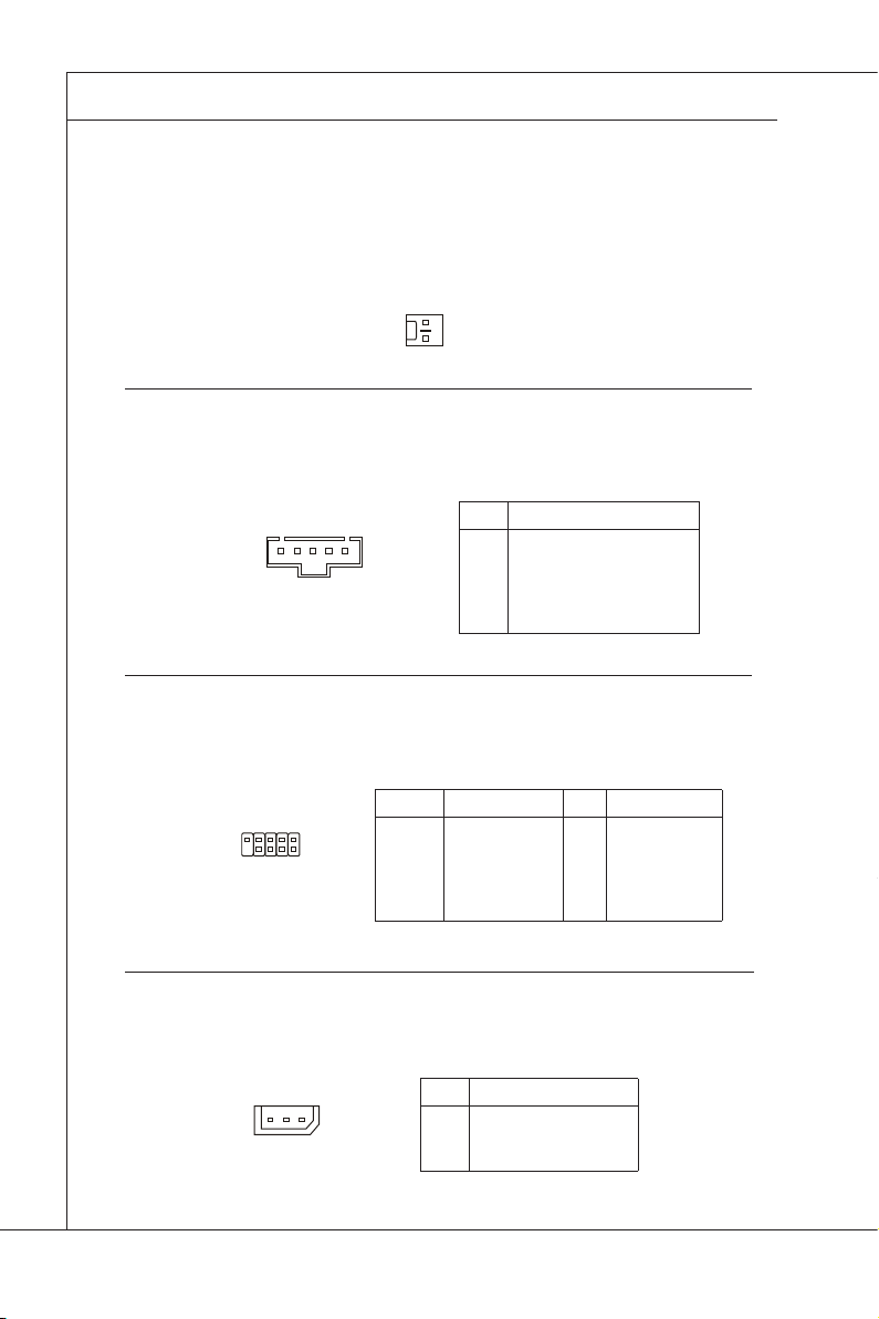
SPI Flash ROM Connector: J2
This connector is used to ash SPI ash ROM.
PIN SIGNAL PIN SIGNAL
9
10
1
2
1
3
5
7
9
+3.3V DUAL
SPI_MISO
SPI_CS0#_R
GND
SPI_HOLD#
2
4
6
8
10
+3.3V DUAL
SPI_MOSI_R
SPI_CLK_R
GND
NC
IPMB Connector: JIPMB1
This connector is used to connect the IPMB (Intelligent Platform Management
Bus) SMBus.
PIN SIGNAL
1
1
SMB_IPMB_5VSB_DAT
2
GND
3
SMB_IPMB_5VSB_CLK
2-14
Page 29
MS-96E0
MS-96E0
LCD Panel Connector: JLCD1
This connector is provided to connect an LCD panel as a way to monitor the current status of the connected system.
PIN SIGNAL
5
6
1
2
1
2
3
4
5
COM SOUT
COM SIN
GND
5V Dual
5V Dual
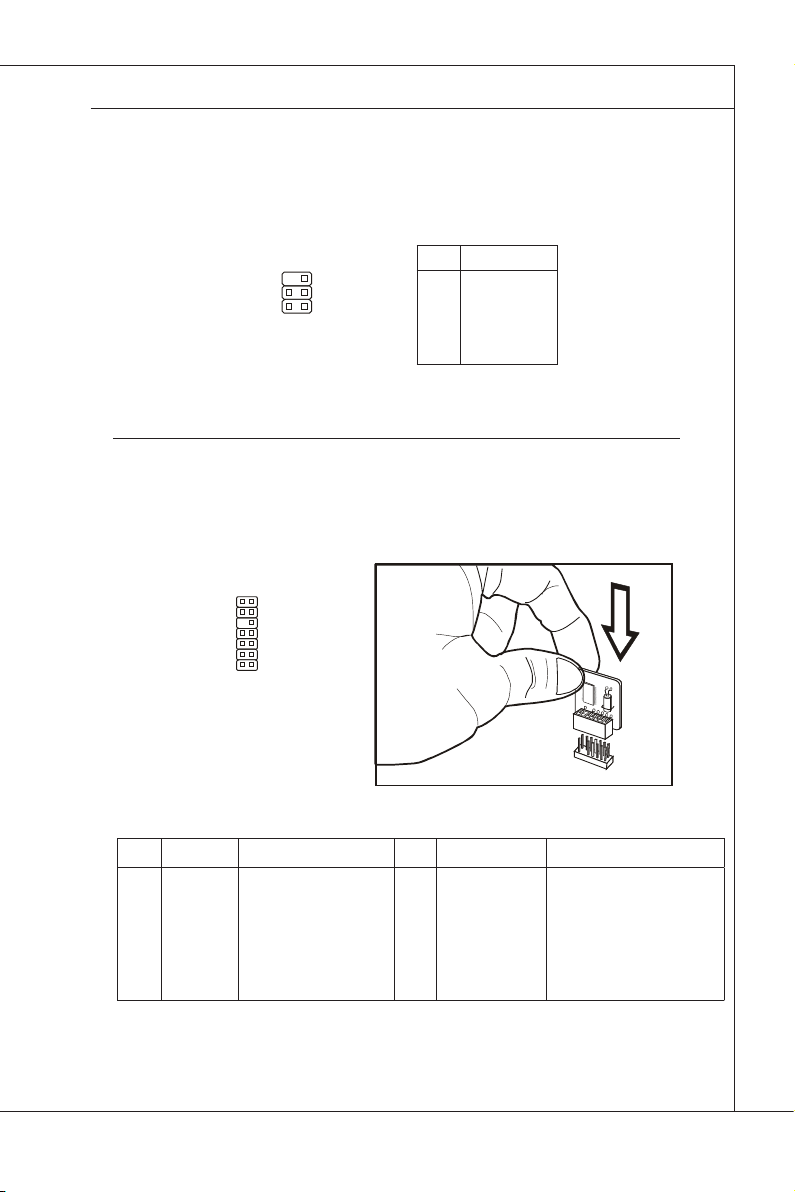
TPM Connector: JTPM1 (Optional)
This connector connects to an optional TPM (Trusted Platform Module). Please
refer to the TPM security platform manual for more details.
13
14
1
2
PIN SIGNAL DESCRIPTION PIN SIGNAL DESCRIPTION
1
LCLK
3
LRST#
5
LAD0
7
LAD1
9
LAD2
11
LAD3
13
LFRAME#
LPC clock
LPC reset
LPC address & data pin0
LPC address & data pin1
LPC address & data pin2
LPC address & data pin3
LPC Frame
2
4
6
8
10
12
14
3V dual/3V_STB
VCC3
SIRQ
VCC5
KEY
GND
GND
3V dual or 3V standby power
3.3V power
Serial IRQ
5V power
No pin
Ground
Ground
2-15
Page 30
Hardware Setup
MS-96E0
▍
JuMper
BIOS Write Protect Jumper: JBIOS_WP
This jumper is used to enable/disable the BIOS ash. When you intend to update
the BIOS code, uncap this jumper rst. Under normal operation, we suggest that
you disable the BIOS ash by capping this jumper to protect the system BIOS
from virus infection.
JBIOS_WP
Disable BIOS Flash
Enable BIOS Flash
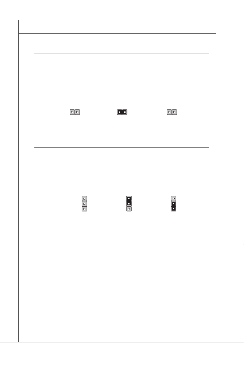
BIOS Recovery Jumper: RECOVERY
Users can short connect pin#2-3 to recover the system BIOS with a Recovery
Floppy. When the system is done with the job, the buzzer will beep to remind the
user to set the jumper to its normal state (pin#1-2 short connected).
1
RECOVERY
Normal (default) 1BIOS recovery
1
2-16
Page 31

MS-96E0
SAS ID Jumper: JSASID1
This jumper is provided to specify the SAS ID.
MS-96E0
JSASID1
MEGA RAID ID IR RAID ID
Clear CMOS Jumper: CLR_CMOS
There is a CMOS RAM onboard that has a power supply from an external battery
to keep the data of system conguration. With the CMOS RAM, the system can
automatically boot OS every time it is turned on. If you want to clear the system
conguration, set the jumper to clear data.
1
CLR_CMOS
1
Keep Data
1
Clear Data
Important
You can clear CMOS by shorting 2-3 pin while the system is off. Then return to
1-2 pin position. Avoid clearing the CMOS while the system is on; it will damage
the mainboard.
2-17
Page 32

Hardware Setup
▍
SLot
PCI (Peripheral Component Interconnect) Express Slot
The PCI Express slots support PCI-E interface expansion cards.
PCI Express x16 slot
PCI_E1: PCI-E 2�0 x16
▶
PCI Express x4 slot
PCI_E2: PCI-E 2�0 x4;
▶
PCI_E3: PCI-E 1�0 x4;
▶
PCI_E4/ PCI_E5: These are proprietary
▶
slots for MS-95X4 SAS card� Please DO
NOT plug other cards into these two slots�
PCI (Peripheral Component Interconnect) Slot
The PCI slot supports LAN card, SCSI card, USB card, and other add-on cards
that comply with PCI specications.
32-bit PCI slot
Important
When adding or removing expansion cards, make sure that you unplug the power
supply rst. Meanwhile, read the documentation for the expansion card to congure any necessary hardware or software settings for the expansion card, such as
jumpers, switches or BIOS conguration.
2-18
Page 33

Chapter 3
BIOS Setup
This chapter provides information on the BIOS Setup
program and allows you to congure the system for optimum use.
You may need to run the Setup program when:
An error message appears on the screen during
■
the system booting up, and requests you to run
SETUP.
You want to change the default settings for cus
■
tomized features.
-
2-3-1
Page 34

BIOS Setup
MS-96E0
▍
enterinG Setup
Power on the computer and the system will start POST (Power On Self Test)
process. When the message below appears on the screen, press <DEL> key to
enter Setup.
Press DEL to enter SETUP
If the message disappears before you respond and you still wish to enter Setup,
restart the system by turning it OFF and On or pressing the RESET button. You
may also restart the system by simultaneously pressing <Ctrl>, <Alt>, and <De
lete> keys.
Important
The items under each BIOS category described in this chapter are under
•
continuous update for better system performance. Therefore, the description
may be slightly different from the latest BIOS and should be held for reference
only.
Upon boot-up, the 1st line appearing after the memory count is the BIOS ver
•
sion. It is usually in the format:
A96E0IMS V1.0 012110 where:
1st digit refers to BIOS maker as A = AMI, W = AWARD, and
P = PHOENIX.
2nd - 5th digit refers to the model number.
6th digit refers to the chipset as I = Intel, N = NVIDIA, A = AMD and
V = VIA.
7th - 8th digit refers to the customer as MS = all standard customers.
V1.0 refers to the BIOS version.
012110 refers to the date this BIOS was released.
-
-
3-2
Page 35

MS-96E0
MS-96E0
Control Keys
← → Select Screen
↑ ↓ Select Item
+ - Change Field
Tab Select Field
F1 General Help
F10 Save and Exit
Esc Exit
Getting Help
After entering the Setup menu, the rst menu you will see is the Main Menu.
Main Menu
The main menu lists the setup functions you can make changes to. You can use
the arrow keys ( ↑↓ ) to select the item. The on-line description of the highlighted
setup function is displayed at the bottom of the screen.
Sub-Menu
If you nd a right pointer symbol (as shown in the right
view) appears to the left of certain elds that means a
sub-menu can be launched from this eld. A sub-menu
contains additional options for a eld parameter. You can use arrow keys ( ↑↓ ) to
highlight the eld and press <Enter> to call up the sub-menu. Then you can use
the control keys to enter values and move from eld to eld within a sub-menu.
If you want to return to the main menu, just press the <Esc >.
General Help <F1>
The BIOS setup program provides a General Help screen. You can call up this
screen from any menu by simply pressing <F1>. The Help screen lists the ap
propriate keys to use and the possible selections for the highlighted item. Press
<Esc> to exit the Help screen.
-
3-3
Page 36

BIOS Setup
MS-96E0
▍
the Menu bar
Main
▶
Use this menu for basic system congurations, such as time, date etc.
Advanced
▶
Use this menu to setup the items of special enhanced features.
Boot
▶
Use this menu to specify the priority of boot devices.
Security
▶
Use this menu to set supervisor and user passwords.
Chipset
▶
This menu controls the advanced features of the onboard Northbridge and South
bridge.
Exit
▶
This menu allows you to load the BIOS default values or factory default settings
into the BIOS and exit the BIOS setup utility with or without changes.
-
3-4
Page 37

MS-96E0
MS-96E0
Main
AMI BIOS, Processor, System Memory
▶
These items show the rmware and hardware specications of your system.
Read only.
System Time
▶
This setting allows you to set the system time. The time format is <Hour> <Min
ute> <Second>.
System Date
▶
This setting allows you to set the system date. The date format is <Day>, <Month>
<Date> <Year>.
-
3-5
Page 38

BIOS Setup
MS-96E0
▍
advanced
CPU Conguration▶
3-6
Page 39

MS-96E0
C1E Support
▶
When the C1E Support (Enhanced Halt Powerdown State) is enabled, the
processor will transition to a lower core to bus ratio and lower voltage ID
driven by the processor to the voltage regulator before entering Halt Pow
erdown State (C1). Not all porcessors support Enhanced Halt Powerdown
State (C1E).
Intel(R) HT Technology
▶
The processor uses Hyper-Threading technology to increase transaction
rates and reduces end-user response times. The technology treats the two
cores inside the processor as two logical processors that can execute instruc
tions simultaneously. In this way, the system performance is highly improved.
If you disable the function, the processor will use only one core to execute the
instructions. Please disable this item if your operating system doesn’t support
HT Function, or unreliability and instability may occur.
Intel(R) SpeedStep(tm) Tech
▶
EIST (Enhanced Intel SpeedStep Technology) allows the system to dynami
cally adjust processor voltage and core frequency, which can result in decreased average power consumption and decreased average heat production.
IDE Conguration
▶
MS-96E0
-
-
-
SATA Conguration, SATA#2 Conguration
▶
This setting species the SATA controller mode.
Congure SATA as
▶
This setting species the operation mode of the installed SATA drive.
3-7
Page 40

BIOS Setup
MS-96E0
▍
Primary/Secondary/Third/Fourth/Fifth IDE Master/Slave
▶
[Type] Press PgUp/<+> or PgDn/<-> to select [Manual], [None] or [Auto] type.
[LBA/Large Mode] Enabling LBA causes Logical Block Addressing to be used in place of
[B loc k( Mul ti- Sec to r
Transfer)]
[PIO Mode] Indicates the type of PIO (Programmed Input/Output)
[DMA Mode] Indicates the type of Ultra DMA
[S.M.A.R.T.] This allows you to activate the S.M.A.R.T. (Self-Monitoring Analysis &
[32 Bit Data Transfer] Enables 32-bit communication between CPU and IDE controller
Super IO Conguration
▶
Note that the specications of your drive must match with the drive
table. The hard disk will not work properly if you enter improper information for this category. If your hard disk drive type is not matched or
listed, you can use [Manual] to dene your own drive type manually.
Cylinders, Heads and Sectors
Any selection except Disabled determines the number of sectors transferred per block
Reporting Technology) capability for the hard disks. S.M.A.R.T is a utility that monitors your disk status to predict hard disk failure. This gives
you an opportunity to move data from a hard disk that is going to fail to
a safe place before the hard disk becomes ofine.
Serial Port 1 Address, Serial Port 2 Address
▶
Select an address for the serial port 1/2.
Serial Port 1 IRQ, Serial Port 2 IRQ
▶
Select a corresponding interrupt for the serial port 1/2.
3-8
Page 41

MS-96E0
AHCI Conguration
▶
AHCI BIOS Support
▶
This BIOS feature controls the SATA controller’s AHCI (Advanced Host Con
troller Interface) functionality. It is a new interface specication that enables
advanced SATA features like Native Command Queuing (NCQ) and hot-plugging.
AHCI Port 0/ 1/ 2/ 3/ 4/ 5
▶
Press [Enter] to view the submenu of advanced settings for AHCI ports.
MS-96E0
-
3-9
Page 42

BIOS Setup
MS-96E0
▍
SATA Port 0
▶
This setting controls the SATA port 0.
S�M�A�R�T�
▶
This allows you to activate the S.M.A.R.T. (Self-Monitoring Analysis & Re
porting Technology) capability for the hard disks. S.M.A.R.T is a utility that
monitors your disk status to predict hard disk failure. This gives you an opportunity to move data from a hard disk that is going to fail to a safe place
before the hard disk becomes ofine.
Event Log Conguration
▶
-
View Event Log
▶
Press [Enter] to view the contents of the DMI event log.
Clear Event Log
▶
When this setting is set to [OK], the DMI event log will be cleared instantly.
3-10
Page 43

MS-96E0
Intel VT-d Conguration
▶
Intel VT-d
▶
Intel Virtualization Technology for Directed I/O (Intel VT-d) provides the ca
pability to ensure improved isolation of I/O resources for greater reliability,
security, and availability.
Coherency Support
▶
This setting indicates if hardware access to the root, context, page-table and
interrupt-remap structures are coherent (snooped) or not.
MS-96E0
-
3-11
Page 44

BIOS Setup
MS-96E0
▍
IPMI 2.0 Conguration
▶
Status of BMC, BMC Firmware Version
▶
These settings show the status of the BMC (Baseboard Management Control
ler) chip and its rmware version. Read only.
View BMC System Event Log
▶
Use this function to view system event logs recorded by BMC.
-
Clear BMC System Event Log
▶
Use this function to clear system event logs recorded by BMC.
3-12
Page 45

MS-96E0
MS-96E0
BMC LAN Conguration
▶
Notify BMC IP Source
▶
Use this setting to check the BMC IP source.
Current IP Address in BMC, Current Subnet Mask in BMC, Current
▶
Gateway in BMC
Use these settings to view the IP address, subnet mask, and gateway in
BMC.
Hardware Health Information
▶
These items display the current status of all of the monitored hardware de
vices/components such as voltages, temperatures and all fans’ speeds.
-
3-13
Page 46

BIOS Setup
MS-96E0
▍
Remote Access Conguration
▶
Remote Access
▶
The setting enables/disables the remote access function. When set to [En
abled], users may congure the following settings for remote access type and
parameters.
Serial Port Number, Base Address, IRQ, Serial Port Mode
▶
Use these settings to congure ports for remote access.
Flow Control
▶
Flow control is the process of managing the rate of data transmission between
two nodes. It’s the process of adjusting the ow of data from one device to another to ensure that the receiving device can handle all of the incoming data.
This is particularly important where the sending device is capable of sending
data much faster than the receiving device can receive it.
Redirection After BIOS POST
▶
This setting determines whether or not to keep terminals?console redirection
running after the BIOS POST has booted.
Terminal Type
▶
To operate the system’s console redirection, you need a terminal supporting
ANSI terminal protocol and a RS-232 null modem cable connected between
the host system and terminal(s). This setting species the type of terminal
device for console redirection.
VT-UTF8 Combo Key Support
▶
This setting enables/disables the VT-UTF8 combination key support for ANSI/
VT100 terminals.
Sredir Memory Display Delay
▶
Use this setting to set the delay in seconds to display memory information.
-
3-14
Page 47

MS-96E0
Trusted Computing
▶
TCG/TPM Support
▶
This setting controls the Trusted Platform Module (TPM) designed by the
Trusted Computing Group (TCG). TPMs are special-purpose integrated cir
cuits (ICs) built into a variety of platforms to enable strong user authentica
tion and machine attestation -- essential to prevent inappropriate access to
condential and sensitive information and to protect against compromised
networks.
Execute TPM Command
▶
TPM commands are managed through a child node of the TPM Management
console named Command Management. To block or allow a TPM command is
a task that local administrators can perform during the setup or re-conguration of a TPM-equipped computer.
TPM Enable/Disable Status
▶
This setting displays the TPM enable/disable status. Read only.
TPM Owner Status
▶
This setting shows the TPM ownership. Read only.
MS-96E0
-
-
3-15
Page 48

BIOS Setup
MS-96E0
▍
APM Conguration
▶
Resume On RTC Alarm
▶
When [Enabled], your can set the date and time at which the RTC (real-time
clock) alarm awakens the system from suspend mode.
3-16
Page 49

MS-96E0
boot
Boot Settings Conguration
▶
MS-96E0
Quick Boot
▶
Enabling this setting will cause the BIOS power-on self test routine to skip
some of its tests during bootup for faster system boot.
3-17
Page 50

BIOS Setup
MS-96E0
▍
Quiet Boot
▶
This BIOS feature determines if the BIOS should hide the normal POST mes
sages with the motherboard or system manufacturer’s full-screen logo.
When it is enabled, the BIOS will display the full-screen logo during the bootup sequence, hiding normal POST messages.
When it is disabled, the BIOS will display the normal POST messages, instead
of the full-screen logo.
Please note that enabling this BIOS feature often adds 2-3 seconds of delay
to the booting sequence. This delay ensures that the logo is displayed for a
sufcient amount of time. Therefore, it is recommended that you disable this
BIOS feature for a faster boot-up time.
AddOn ROM Display Mode
▶
This item is used to determine the display mode when an optional ROM is
initialized during POST. When set to [Force BIOS], the display mode used by
AMI BIOS is used. Select [Keep Current] if you want to use the display mode
of optional ROM.
Bootup Num-Lock
▶
This setting is to set the Num Lock status when the system is powered on.
Setting to [On] will turn on the Num Lock key when the system is powered on.
Setting to [Off] will allow users to use the arrow keys on the numeric keypad.
Wait For ‘F1’ If Error
▶
When this setting is set to [Enabled] and the boot sequence encounters an
error, it asks you to press F1. If disabled, the system continues to boot without
waiting for you to press any keys.
Hit ‘DEL’ Message Display
▶
Set this option to [Disabled] to prevent the message as follows:
Hit Del if you want to run setup
It will prevent the message from appearing on the rst BIOS screen when
the computer boots. Set it to [Enabled] when you want to run the BIOS Setup
Utility.
Boot Device Priority
▶
The items allow you to set the sequence of boot devices where BIOS attempts to
load the disk operating system. First press <Enter> to enter the sub-menu. Then
you may use the arrow keys ( ↑↓ ) to select the desired device, then press <+>,
<-> or <PageUp>, <PageDown> key to move it up/down in the priority list.
Removable Drives
▶
This setting allows users to set the priority of the removable devices. First press
<Enter> to enter the sub-menu. Then you may use the arrow keys ( ↑↓ ) to select
the desired device, then press <+>, <-> or <PageUp>, <PageDown> key to move
it up/down in the priority list.
-
3-18
Page 51

MS-96E0
MS-96E0
Security
Supervisor Password / Change Supervisor Password
▶
Supervisor Password controls access to the BIOS Setup utility. These settings
allow you to set or change the supervisor password.
User Password / Change User Password
▶
User Password controls access to the system at boot. These settings allow you
to set or change the user password.
Chassis Intrusion
▶
The eld enables or disables the feature of recording the chassis intrusion status
and issuing a warning message if the chassis is once opened. To clear the warn-
ing message, set the eld to [Reset]. The setting of the eld will automatically
return to the default value later.
3-19
Page 52

BIOS Setup
MS-96E0
▍
chipSet
CPU Bridge Conguration
▶
Memory Frequency
▶
This item allows you to select the memory frequency.
3-20
Page 53

MS-96E0
Memory Mode
▶
This setting species the memory mode.
North Bridge Conguration
▶
South Bridge Conguration
▶
MS-96E0
82574 LAN#1 / LAN#2 OPROM
▶
The items enable or disable the initialization of the onboard LAN Boot ROMs
during bootup. Selecting [Disabled] will speed up the boot process.
3-21
Page 54

BIOS Setup
MS-96E0
▍
Restore on AC Power Loss
▶
This setting species whether your system will reboot after a power failure or
interrupt occurs. Available settings are:
[Power Off] Leaves the computer in the power off state.
[Power On] Leaves the computer in the power on state.
[Last State] Restores the system to the previous status before power
failure or interrupt occurred.
3-22
Page 55

MS-96E0
MS-96E0
exit
Save Changes and Exit
▶
Save changes to CMOS and exit the Setup Utility.
Discard Changes and Exit
▶
Abandon all changes and exit the Setup Utility.
Discard Changes
▶
Abandon all changes and continue with the Setup Utility.
Load Optimal Defaults
▶
Use this menu to load the default values set by the mainboard manufacturer
specically for optimal performance of the mainboard.
Load Failsafe Defaults
▶
Use this menu to load the default values set by the BIOS vendor for stable sys
tem performance.
-
3-23
Page 56

Page 57

Appendix A
Intel ICH10R SATA
RAID
This appendix will assist users in conguring and enabling RAID functionality on platforms.
C-A-1
Page 58

Intel ICH10R SATA RAID
MS-96E0
▍
introduction
The ICH10R provides a hybrid solution that combines 6 independent SATAII ports for
support of up to 6 Serial ATAII (Serial ATAII RAID) drives.
Serial ATAII (SATAII) is the latest generation of the ATA interface. SATA hard drives
deliver blistering transfer speeds up to 3 Gb/s. Serial ATA uses long, thin cables, mak
ing it easier to connect your drive and improving the airow inside your PC. The most
outstanding features are:
Supports 3 Gb/s transfers with CRC error checking.
1.
Supports Hot-plug-n-play feature.
2.
Data handling optimizations including tagged command queuing, elevator seek and
3.
packet chain command.
Intel® ICH10R offers RAID level 0 (Striping), RAID level 1 (Mirroring and Duplexing),
RAID level 5 (Block Interleaved Distributed Parity), RAID level 10 (A Stripe of Mirrors) ,
Intel® Martix Storage Technology and Intel® Rapid Recover Technology.
RAID 0 breaks the data into blocks which are written to separate hard drives. Spread
ing the hard drive I/O load across independent channels greatly improves I/O perfor
mance.
RAID 1 provides data redundancy by mirroring data between the hard drives and pro
vides enhanced read performance.
RAID 5 Provides data striping at the byte level and also stripe error correction informa
tion. This results in excellent performance and good fault tolerance. Level 5 is one of the
most popular implementations of RAID.
RAID 10 Not one of the original RAID levels, multiple RAID 1 mirrors are created, and a
RAID 0 stripe is created over these.
Intel® Matrix RAID Technology is the advanced ability for two RAID volumes to share the
combined space of two hard drives being used in unison.
Intel® Rapid Recover Technology utilizes RAID 1 functionality to copy data from a designated Master drive to a designated Recovery drive. The size of the Master drive must
be less than or equal to the size of the Recovery drive. When a Recovery volume is
created, complete capacity of the Master drive will be used as the Master volume. Only
one Recovery Volume can exist on a system. There are 2 methods of updating the
data on the Master to the Recovery drive. They are Continuous Update Policy and On
Request Update Policy.
-
-
-
-
-
Important
The least number of hard drives for RAID 0, RAID 1, Recovery or Matrix mode is 2. The
least number of hard drives for RAID 10 mode is 4. And the least number of hard drives
for RAID 5 mode is 3.
All the information/ volumes/ pictures listed in your system might differ from the illustrations in this appendix.
A-2
Page 59

MS-96E0
MS-96E0
bioS confiGuration
The Intel Matrix Storage Manager Option ROM should be integrated with the system
BIOS on all motherboards with a supported Intel chipset. The Intel Matrix Stroage Manager Option ROM is the Intel RAID implementation and provides BIOS and DOS disk
services. Please use <Ctrl> + <I> keys to enter the “Intel® RAID for Serial ATA” status
screen, which should appear early in system boot-up, during the POST (Power-On Self
Test). Also, you need to enable the RAID function in BIOS to create, delete and reset
RAID volumes.
Using the Intel Matrix Stroage Manager Option ROM
Creating, Deleting and Resetting RAID Volumes:
The Serial ATA RAID volume may be congured using the RAID Conguration utility
stored within the Intel RAID Option ROM. During the Power-On Self Test (POST), the
following message will appear for a few seconds:
Important
The “Drvice Model”, “Serial #” and “Size” in the following example might be different
from your system.
After the above message shows, press <Ctrl> and <I> keys simultaneously to enter the
RAID Conguration Utility.
Important
The following procedure is only available with a newly-built system or if you are reinstalling your OS. It should not be used to migrate an existing system to RAID.
A-3
Page 60

Intel ICH10R SATA RAID
MS-96E0
▍
After pressing the <Ctrl> and <I> keys simultaneously, the following window will appear:
Create RAID Volume
■
Select option 1 Create RAID Volume” and press <Enter> key. The following screen
1.
appears. Then in the Name eld, specify a RAID Volume name and then press the
<TAB> or <Enter> key to go to the next eld.
Use the arrow keys to select the RAID level best suited to your usage model in
2.
RAID Level.
A-4
Page 61

MS-96E0
In the Disk eld, press <Enter> key and the following screen appears. Use <Space>
3.
key to select the disks you want to create for the RAID volume, then click <Enter>
key to nish selection.
Then select the strip value for the RAID array by using the “upper arrow” or
4.
“down arrow” keys to scroll through the available values, and pressing the
<Enter> key to select and advance to the next eld. The available values
range from 4KB to 128 KB in power of 2 increments. The strip value should
be chosen based on the planned drive usage. Here are some typical values:
RAID0 -128KB / RAID10 - 64KB / RAID5 - 64KB.
Then select the capacity of the volume in the Capacity eld. The default value is the
5.
maximum volume capacity of the selected disks.
MS-96E0
A-5
Page 62

Intel ICH10R SATA RAID
MS-96E0
▍
Important
Since you want to create two volumes (Intel Matrix RAID Technology), this default size
(maximum) needs to be reduced. Type in a new size for the rst volume. As an example:
if you want the rst volume to span the rst half of the two disks, re-type the size to be
half of what is shown by default. The second volume, when created, will automatically
span the remainder of two hard drives.
Then the following screen appears for you to conrm if you are sure to create the
6.
RAID volume. Press <Y> to continue.
A-6
Then the following screen appears to indicate that the creation is nished.7.
Page 63

MS-96E0
Delete RAID Volume
■
Here you can delete the RAID volume, but please be noted that all data on RAID
drives will be lost.
Important
If your system currently boots to RAID and you delete the RAID volume in the Intel
RAID Option ROM, your system will become unbootable.
MS-96E0
Select option 2
ter> key to select a RAID volume for deletion. Then press <Delete> key to delete
the selected RAID volume. The following screen appears.
Press <Y> key to accept the volume deletion.
Delete RAID Volume from the main menu window and press <En-
A-7
Page 64

Intel ICH10R SATA RAID
MS-96E0
▍
Reset Disks to Non-RAID
■
Select option 3 Reset Disks to Non-RAID and press <Enter> to delete the RAID
volume and remove any RAID structures from the drives. The following screen
appears:
Press <Y> key to accept the selection.
Important
You will lose all data on the RAID drives and any internal RAID structures when
•
you perform this operation.
Possible reasons to “Reset Disks to Non-RAID” could include issues such as
•
incompatible RAID congurations or a failed volume or failed disk.
A-8
Page 65

MS-96E0
Recovery Volume Options
■
Select option 4 Recovery Volume Options and press <Enter> to change recovery volume mode. The following screen appears:
Recovery mode will change from Continuous Update to On-Request after you
enable “Only Recovery Disk” or “Only Master Disk”.
MS-96E0
A-9
Page 66

Intel ICH10R SATA RAID
MS-96E0
▍
inStaLLinG driver
Install Driver in Windows Server 2008/2003
Install Driver in Windows Server 2008/2003
■
The following details the installation of the drivers while installing operating system.
When you start installing Windows Server 2008/2003, you may encounter a
1.
message stating, etup could not determine the type of one or more mass storage devices installed in your system? If this is the case, then you are already
in the right place and are ready to supply the driver. For Windows 2003, if this
is not the case, then press F6 when prompted at the beginning of Windows
setup.
Press the “S” key to select “Specify Additional Device”.
2.
You should be prompted to insert a disk containing the Intel
3.
Important
Please follow the instruction below to make an “Intel® RAID Driver” for yourself.
Insert the MSI CD into the CD-ROM drive.
1.
Click the “Browse CD” on the Setup screen.
2.
Copy all the contents in \\SATA2_RAID\f6py3288 (32 bits) or \\SATA2_
3.
RAID\f6py6488 (64 bits) to a formatted disk.
The driver disk for Intel® ICH10R RAID Controller is done.
4.
4.
During the Operating system installation, after selecting the location to install,
click on “Load Driver” button to install a third party SCSI or RAID driver.
5.
When prompted, insert the disk (CD/DVD or USB) you created in step 3 and
press Enter.
You should be shown a list of available SCSI Adapters.
6.
Select the appropriate Intel RAID controller and press ENTER.
7.
The next screen should conrm that you have selected the Intel
8.
ler. Press ENTER again to continue.
You have successfully installed the Intel
9.
setup should continue.
Leave the disk in the drive until the system reboots itself. Windows setup will
10.
need to copy the les from the disk again after the RAID volume is formatted,
and Windows setup starts copying les.
®
SATA RAID driver, and Windows
®
RAID driver.
®
RAID control-
A-10
Page 67

MS-96E0
Existing Windows Server 2008/2003 Driver Installation
■
Insert the MSI CD into the CD-ROM drive.
1.
The CD will auto-run and the setup screen will appear.
2.
Under the Driver tab, click on Intel IAA RAID Edition.
3.
The drivers will be automatically installed.
4.
Conrming Windows Server 2008/2003 Driver Installation
■
Under Windows Server 2008/2003, open the Control Panel from My Computer
1.
followed by the System icon.
Choose the Hardware tab, then click the Device Manager tab.
2.
Click the “+” in front of the SCSI and RAID Controllers hardware type. The
3.
driver Intel(R) ICH10R SATA RAID Controller should appear.
MS-96E0
A-11
Page 68

Intel ICH10R SATA RAID
MS-96E0
▍
inStaLLinG Software
Install Intel Matrix Storage Console
The Intel Application Accelerator RAID Edition driver may be used to operate the
hard drive from which the system is booting or a hard drive that contains important
data. For this reason, you cannot remove or un-install this driver from the system
after installation; however, you will have the ability to un-install all other non-driver
components.
Insert the MSI CD and click on the
Intel IAA RAID Editor to install the software.
A-12
Click on this item
Page 69

MS-96E0
The InstallShield Wizard will begin automatically for installation.
Click on the Next button to proceed the installation in the welcoming window.
MS-96E0
A-13
Page 70

Intel ICH10R SATA RAID
MS-96E0
▍
The window shows the components to be installed. Click Next button to continue.
After reading the license agreement in the following window, click Yes button to continue.
A-14
Page 71

MS-96E0
MS-96E0
The following window appears to show the Readme File Information. It shows the system requirements and installation information.
Once the installation is complete, the following window appears.
A-15
Page 72

Intel ICH10R SATA RAID
MS-96E0
▍
raid MiGration inStructionS
The Intel Matrix Storage Console offers the exibility to upgrade from a single Serial ATA
(SATA) hard drive to RAID conguration when an additional SATA hard drive is added to
the system. This process will create a new RAID volume from an existing disk. However,
several important steps must be followed at the time the system is rst congured in
order to take advantage of RAID when upgrading to a second SATA hard drive:
BIOS must be congured for RAID before installing Windows on the single SATA
1.
hard drive. Refer to “BIOS section” properly setting.
Install the Intel Application Accelerator RAID Driver during Windows Setup. Refer to
2.
“Installing Software” for instructions on installing the driver during Windows Setup.
Install the Intel Matrix Storage Console after the operating system is installed.
3.
To create a volume from an existing disk, complete the following steps:
Important
A “Create from Existing Disk” operation will delete all existing data from the added disk
and the data cannot be recovered. It is critical to backup all important data on the added
disk before proceeding. However, during the migration process, the data on the source
disk is preserved.
After the Intel Matrix Storage Console has been successfully installed and the system
has rebooted, click on the Intel Application Accelerator shortcut link (
grams --> Intel Matrix Storage Manager --> Intel Matrix Storage Console) and the following window will appear:
A-16
Start --> All Pro-
Page 73

MS-96E0
MS-96E0
Create RAID Volume from Existing Disk
To create a RAID volume from an existing disk, choose Action --> Create RAID Volume
from Existing Hard Drive.
The Create RAID Volume from Existing Hard Drive Wizard pops up to lead you for the
following procedure. Click Next to continue.
A-17
Page 74

Intel ICH10R SATA RAID
MS-96E0
▍
(1) Congure Volume
Here you can congure the new RAID volume by entering the volume name, selecting
the RAID level and strip size.
RAID Volume Name:
■
A desired RAID volume name needs to be typed in where the “Volume_0000” text
currently appears above. The RAID volume name has a maximum limit of 16 characters. The RAID volume name must also be in English alphanumeric ASCII characters.
RAID Level:
■
Select the desired RAID level:
RAID 0 (Performance) :
A volume optimized for performance will allow you to access your data more quick
ly.
RAID 1 (Redundancy) :
A volume optimized for data redundancy will provide you with a realtime duplicate
copy of your data. Note: Only half of the available volume space will be available for
data storage.
RAID 5 (Useful) :
RAID 5 can be used on three or more disks, with zero or more spare-disks. The
resulting RAID-5 device size will be (N-1)*S, where N is the how many drive, S is the
size of the smallest drive in the array. If one of the disks fail, all data are still intact. It
can rebuild the disk from the parity information. If spare disks are available, recon
struction will begin immediately after the device failure. If two disks fail simultaneously, all data are lost. RAID-5 can survive one disk failure, but not two or more. Both
read and write performance usually increase, but can be hard to predict how much.
Reads are similar to RAID-0 reads, writes can be either rather expensive (requiring
read-in prior to write, in order to be able to calculate the correct parity information),
or similar to RAID-1 writes. The write efciency depends heavily on the amount of
A-18
-
-
Page 75

MS-96E0
MS-96E0
memory in the machine, and the usage pattern of the array. Heavily scattered writes
are bound to be more expensive.
RAID 10 (Mirrored Stripes) :
A RAID 1 array of two RAID 0 arrays.
Strip Sizes:
■
Select the desired strip size setting. As indicated, the optimal setting is 128KB. Selecting any other option may result in performance degradation. Even though 128KB
is the recommended setting for most users, you should choose the strip size value
which is best suited to your specic RAID usage model. The most typical strip size
settings are:
4KB: For specialized usage models requiring 4KB strips
8KB: For specialized usage models requiring 8KB strips
16KB: Best for sequential transfers
32KB: Good for sequential transfers
64KB: Good general purpose strip size
128KB: Best performance for most desktops and workstations
(2) Select the source disk
Then select the source disk that you wish to use and then click “-->” to move it to the
“Selected” eld. Then click “Next” to continue.
It is very important to note which disk is the source disk (the one containing all of the
information to be migrated) and which one is the target disk. On a RAID Ready system,
this can be determined by making a note during POST of which port the single disk is
attached to.
You can also use the Intel Application Accelerator RAID Edition utility before the second
disk is installed to verify the Port and serial number of the drive that contains all the
data.
A-19
Page 76

Intel ICH10R SATA RAID
MS-96E0
▍
(3) Select Member Hard Drive(s)
Then select the member disk (the target disk) that you wish to use and then click “-->”
to move it to the “Selected” eld. Then click “Next” to continue.
Please note that the existing data on the selected hard drive(s) will be deleted perma
nently. Do not forget to back up all the important data before continuing.
-
A-20
Page 77

MS-96E0
MS-96E0
(4) Specify Volume Size
Specify the amount of available array space to be used by the new RAID volume. You
may enter the amount in the space or use the slider to specify. It is recommended you
use 100% of the available space for the optimized usage. For RAID 0 volume, if you do
not specify 100% of the hard drive space, the rest hard drive space will be worked as
RAID 1 volume, which is the new technology called Intel Matrix RAID. Then click “Next”
to continue.
(5) Start Creating RAID Volume from Existing Hard Drive Wizard
Before you continue the procedure of RAID volume creation from existing hard drive,
read the dialogue box below carefully. Please note that once you click “Finish”, the
existing data on the selected hard drive(s) will be deleted permanently and this opera
tion cannot be undone. It is critical that you backup all important data before selecting
“Finish” to start the migration process.
-
A-21
Page 78

Intel ICH10R SATA RAID
MS-96E0
▍
(6) Start Migration
The migration process may take up to two hours to complete depending on the size of
the disks being used and the strip size selected. A dialogue window will appear stat
ing that the migration process may take considerable time to complete, meanwhile a
popup dialogue at the taskbar will also show the migration status. While you can still
continue using your computer during the migration process, once the migration process
starts, it cannot be stopped. If the migration process gets interrupted and your system
is rebooted for any reason, it will pick up the migration process where it left off. You will
be provided with an estimated completion time (the remaining time will depend on your
system) once the migration process starts.
-
The following screen appears if the migration process is completed successfully. Then
you have to reboot your system to use the full capacity of the new volume.
A-22
Page 79

MS-96E0
MS-96E0
recovery voLuMe creation
A recovery volume can be created using either Basic mode or Advanced mode in the
Intel Matrix Storage Console.
Recovery Volume in Basic Mode Creation■
Important
Creating a recovery volume will permanently delete any existing data on the drive
selected as the recovery drive. Back up all important data before beginning these
steps.
This option may or may not be available depending on your system conguration.
If you do not see the option listed, refer to Recovery Volume Creation in Advanced
Mode.
To create a recovery volume in Basic mode, use the following steps:
Open the Intel Matrix Storage Console. (
1.
age Manager --> Intel Matrix Storage Console)
Select Protect data using IntelR Rapid Recover Technology.
2.
Start --> All Programs --> Intel Matrix Stor-
Select Yes to conrm volume creation.3.
A-23
Page 80

Intel ICH10R SATA RAID
MS-96E0
▍
Recovery Volume in Advanced Mode Creation■
Important
Creating a recovery volume will permanently delete any existing data on the drive
selected as the recovery drive. Back up all important data before beginning these
steps.
To create a recovery volume in Advanced mode, use the following steps:
1.
Open the Intel Matrix Storage Console. (Start --> All Programs --> Intel Matrix Stor
age Manager --> Intel Matrix Storage Console)
Select Advanced Mode in the View menu.
2.
Select Create Recovery Volume in the Actions menu.
3.
Select Next to continue.4.
-
A-24
Page 81

MS-96E0
Modify the recovery volume name if you wish.
5.
Select a hard drive to be used as the master hard drive for the recovery volume.
6.
Select a hard drive to be used as the recovery hard drive for the recovery volume.7.
MS-96E0
A-25
Page 82

Intel ICH10R SATA RAID
MS-96E0
▍
Select an update policy.8.
Select Finish to begin recovery volume creation.9.
A-26
Page 83

MS-96E0
MS-96E0
deGraded raid array
A RAID 1, RAID 5 or RAID 10 volume is reported as degraded when one of its hard
drive members fails or is temporarily disconnected, and data mirroring is lost. As a
result, the system can only utilize the remaining functional hard drive member. To reestablish data mirroring and restore data redundancy, refer to the procedure below
that corresponds to the current situation.
Missing Hard Drive Member
Make sure the system is powered off.
1.
Reconnect the hard drive.
2.
Reboot the system to Windows; the rebuild will occur automatically.
3.
Failed Hard Drive Member
Make sure the system is powered off.
1.
Replace the failed hard drive with a new one that is of equal or greater capacity.
2.
Reboot the system to Intel RAID Option ROM by press <Ctrl> and <I> keys si
3.
multaneously during the Power-On Self Test (POST).
-
Select the port of the destination disk for rebuilding, and then press ENTER.4.
A-27
Page 84

Intel ICH10R SATA RAID
▍
Exit Intel RAID Option ROM, and then reboot to Windows system.
5.
When prompted to rebuild the RAID volume, click ‘Yes’.
6.
The Intel(R) Storage Utility will be launched. Right-click the new hard drive and
7.
select ‘Rebuild to this Disk’. The ‘Rebuild Wizard’ will be launched which will
guide you through the process of rebuilding to the new hard drive.
A-28
Page 85

Appendix B
LSI SAS RAID (Optional)
This appendix explains how to congure and use the
components of the LSI Logic Integrated RAID (IR) software with LSI SAS 1064/1064E & 1068/1068E controllers.
C-B-1
Page 86

LSI SAS RAID
MS-96E0
▍
1. introduction to inteGrated raid
This section provides an overview of the LSI Logic Integrated RAID solution for LSI
Logic SAS controllers, its features, and its benets.
The LSI Logic Integrated RAID solution provides cost benets for the server or work-
station market where the extra performance, storage capacity, and/or redundancy of a
RAID conguration are required. The two components of Integrated RAID are:
Integrated Mirroring (IM), which provides features of RAID 1 and RAID 1E (RAID 1
■
Enhanced). RAID 1E is also called Integrated Mirroring Enhanced (IME)
Integrated Striping (IS), which provides features of RAID 0
■
By simplifying the IM and IS conguration options and by providing rmware support in
its host adapters, LSI Logic can offer the Integrated RAID solution at a lower cost than
a hardware RAID implementation.
Fusion-MPT™ rmware supports IM and IS volumes. You can congure IM and IS volumes together on the same LSI Logic SAS controller.
Integrated RAID Benets and Features
Low cost RAID volume creation meets the needs of most internal RAID installa-
■
tions
Easy to use - installation and conguration are not complex
■
System can boot from an IM, IME, or IS volume
■
No special OS-specic software required
■
High reliability and data integrity
■
- Non-volatile write journaling
- Physical disks not visible to OS or to application software
Low host CPU and PCI bus utilization
■
Fusion-MPT architecture provides processing power
■
- Shared memory architecture minimizes external memory requests
- Functionality is contained in device hardware and rmware
B-2
Page 87

MS-96E0
MS-96E0
2. inteGrated MirrorinG overview
This section provides an overview of the LSI Logic Integrated Mirroring (IM) feature.
2�1 Introduction
As a result of the shift towards Network Attached Storage (NAS), ISPs need a cost
effective, fault-tolerant solution to protect the operating systems on small form factor,
high-density, rack-mountable servers. The LSI Logic Integrated Mirroring (IM) feature
-- which includes Integrated Mirroring Enhanced (IME) -- provide data protection for
the system boot volume to safeguard critical information such as the operating system
on servers and high performance workstations. The Integrated Mirroring feature gives
customers a robust, high-performance, fault-tolerant solution to their storage needs, at
a lower cost than a dedicated RAID controller.
The Integrated Mirroring feature supports simultaneous mirrored volumes with two disks
(IM) or three to eight disks (IME), to provide fault-tolerant protection for critical data. (If
a hot spare disk is used, the maximum volume size is seven mirrored disks, plus the
hot spare disk.) Up to two IM volumes are supported per SAS controller, with up to ten
drives total per controller.
Note: Ten disk drives is the theoretical upper limit, although the SAS controller
■
itself may support fewer drives.
If a disk in an Integrated Mirroring volume fails, the hot swap capability allows the vol
ume to be easily restored by simply swapping disks. The rmware then automatically
re-mirrors the swapped disk. Additionally, each SAS controller can have one global hot
spare disk available to automatically replace a failed disk in the one or two IM or IME
volumes congured on the controller. The hot spare makes the Integrated
Mirroring volume even more fault-tolerant.
Note: You can congure an Integrated Mirroring volume and an Integrated Striping
■
volume on the same LSI Logic SAS controller.
The IM feature uses the same device drivers as the standard LSI Logic Fusion-MPT
based controllers, providing seamless and transparent fault tolerance. This eliminates
the need for complex backup software or expensive RAID hardware. The IM feature
operates independently from the operating system, in order to conserve system re
sources. The BIOSbased conguration utility makes it easy to congure IM and IME
volumes.
The Integrated Mirroring feature is currently available as an optional component of the
Fusion-MPT architecture on LSI Logic controller products.
B-3
-
-
Page 88

LSI SAS RAID
MS-96E0
▍
2�2 IM Features
LSI Logic Integrated Mirroring and Integrated Mirroring Enhanced support the following
features:
Congurations of one or two IM or IME volumes on the same LSI Logic SAS con-
■
troller. Each volume can consist of two mirrored disks (IM) or three to eight mirrored
disks (IME).
(Optional) One global hot spare disk per controller. If a global hot spare disk is
■
dened, the upper limit for an IME volume is seven mirrored disks.
Mirrored volumes run in optimal mode or in degraded mode (if one mirrored disk
■
fails)
Hot swap capability
■
Presents a single virtual drive to the OS for each IM/IME volume
■
Supports both SAS and SATA disks, although the two types of disks cannot be
■
combined on the same LSI Logic SAS controller
Fusion-MPT architecture
■
Easy-to-use BIOS-based conguration utility (and DOS-based conguration utility
■
for manufacturing use only)
Error notication: OS-specic event log updated by drivers and errors displayed
■
inside the Fusion-MPT BIOS
SES status LED support for Integrated Mirroring disks
■
Write journaling, which allows automatic synchronization of potentially inconsistent
■
data after unexpected power-down situations
Metadata used to store volume conguration on mirrored disks
■
Automatic background resynchronization while host I/Os continue
■
Background media verication ensures that data on the IM volume is accessible
■
B-4
Page 89

MS-96E0
MS-96E0
2�3 IM/IME Description
The LSI Logic Integrated Mirroring (IM) feature supports one or two mirrored volumes
on each LSI Logic SAS controller (or one mirrored volume and one Integrated Striping
volume). Typically, one of these volumes is the boot volume, as shown in Figure 2.1.
This is accomplished through the rmware of the LSI Logic SAS controller that supports
the standard Fusion-MPT interface. The runtime mirroring of the boot disk is transparent
to the BIOS, drivers, and operating system.
Host-based status software monitors the state of the mirrored disks and reports any
error conditions. In Figure 2.1 the system is congured with a second disk as a mirror
of the rst (primary) disk.
The advantage of Integrated Mirroring (RAID 1), is that there is always a mirrored copy
of the data. The disadvantage is that writes take longer because data must be written
twice. On the other hand, performance is actually improved during reads.
Figure 2.2 shows the logical view and physical view of an Integrated Mirroring conguration with two disks in the mirrored volume.
B-5
Page 90

LSI SAS RAID
MS-96E0
▍
An IME volume can be congured with up to eight mirrored disks, or seven mirrored
disks and a global hot spare. Figure 2.3 shows the logical view and physical view of an
Integrated Mirroring Enhanced (IME) volume with three mirrored disks. Each mirrored
stripe is written to a disk and mirrored to an adjacent disk. This type of conguration is
also called RAID 1E.
LSI Logic provides the BIOS-based conguration utility to enable the user to create IM
and IME volumes during initial setup and to recongure them in response to hardware
failures or changes in the environment.
B-6
Page 91

MS-96E0
MS-96E0
2�4 Integrated Mirroring Firmware
This section describes features of the LSI Logic Integrated Mirroring (IM) rmware,
which supports up to two IM volumes per LSI Logic SAS controller.
2�4�1 Host Interface
The IM host interface uses the Message Passing Interface, as described in the Fusion-
MPT Message Passing Interface Specication. Through the Fusion-MPT interface, the
host OS has access to the IM volume as well as the physical disks.
2�4�2 Resynchronization with Concurrent Host I/O Operation
The IM rmware allows Host I/Os to continue on the IM/IME volume while the volume
is being re-synchronized in the background. Resynchronization is attempted after a hot
spare is activated due to a physical device failure, or after a hot swap has occurred to a
physical disk in the IM or IME volume.
2�4�3 Metadata Support
The rmware supports metadata, which describes the IM/IME logical drive conguration stored on each member disk. When the rmware is initialized, each member disk is
queried to read the stored metadata in order to verify the conguration. The usable disk
space for each member disk is adjusted down to leave room for this data.
2�4�4 Hot Swapping
The IM rmware supports hot swapping. The hot-swapped disk is automatically resynchronized in the background, without any host or user intervention. The rmware de-
tects hot swap removal and disk insertion.
Following a hot swap event, the rmware readies the new physical disk by spinning it
up and verifying that it has enough capacity for the mirrored volume. The IM rmware
resynchronizes all hot-swapped disks that have been removed, even if the same disk
is re-inserted. In a two-disk mirrored volume, the IM rmware marks the hot-swapped
disk as the secondary disk and marks the other mirrored disk as the primary disk. The
rmware resynchronizes all data from the primary disk onto the new secondary disk.
2�4�5 SMART Support
The IM rmware enables Mode 6 SMART on the member disks in the mirrored volume.
Mode 6 SMART requires each physical disk to be polled at regular intervals. If a SMART
ASC/ASCQ code is detected on a physical disk in the volume, the rmware processes
the SMART data, and the last received SMART ASC/ASCQ is stored in non-volatile
memory. The IM/IME volume does not support SMART directly, since it is just a logical
representation of the physical disks in the volume.
2�4�6 Hot Spare Disk
One disk can be congured as a global hot spare disk, which protects data on the one
or two volumes congured on the controller. If the IM rmware fails one of the mirrored
disks, the rmware automatically replaces it with the hot spare disk. The IM rmware
then resynchronizes the mirrored data. The IM rmware is automatically notied when
B-7
Page 92

LSI SAS RAID
MS-96E0
▍
the failed disk has been replaced, and the rmware then designates that disk as the
new hot spare.
2.4.7 Media Verication
The IM rmware supports a background media verication feature that runs at regular
intervals when the IM/IME volume is in optimal mode. If the verication command fails
for any reason, the other disk’s data for this segment is read and written to the failing
disk in an attempt to refresh the data. The current Media Verication Logical Block
Address is written to non-volatile memory occasionally to allow Media Verication to
continue approximately where it left off prior to a power-cycle.
2�4�8 Disk Write Caching
The IM rmware disables disk write caching by default. This is done to increase data
integrity, so that the disk write log stored in NVSRAM is always valid. If disk write caching were enabled (not recommended), the disk write log could be invalid.
2�4�9 NVSRAM Usage
For the LSISAS1064/1064E and LSISAS1068/1068E controllers, the IM rmware requires at least a 32K NVSRAM in order to perform write journaling. Write journaling is
used to verify that the mirrored disks in the IM/IME volume are synchronized with each
other.
2�5 Fusion-MPT Support
The BIOS uses the LSI Logic Fusion-MPT interface to communicate to the SAS control-
ler and rmware to enable Integrated Mirroring. This includes reading the Fusion-MPT
conguration to gain access to the parameters that are used to dene behavior between
the SAS controller and the devices connected to it. The Fusion-MPT drivers for all supported operating systems implement the Fusion-MPT interface to communicate with the
controller and rmware.
B-8
Page 93

MS-96E0
MS-96E0
3. creatinG inteGrated MirrorinG voLuMeS
This section describes how to create Integrated Mirroring (IM) and Integrated Mirroring
Enhanced (IME) volumes using the LSI Logic SAS BIOS Conguration Utility (SAS
BIOS CU).
3.1 IM Conguration Overview
You can use the SAS BIOS CU to create one or two IM or IME volumes on each LSI
Logic SAS controller, with an optional global hot spare disk. All disks in an IM or IME
volume must be connected to the same LSI Logic SAS controller.
Although you can use disks of different size in IM and IME volumes, the smallest disk
determines the “logical” size of each disk in the volume. In other words, the excess
space of the larger member disk is not used.
Refer to Section 2.2, “IM Features,” for more information about Integrated Mirroring
volumes.
3�2 Creating IM and IME Volumes
The SAS BIOS CU is part of the Fusion-MPT BIOS. When the BIOS loads during boot
and you see the message about the LSI Logic Conguration Utility, press Ctrl-C to start
the CU. After you do this, the message changes to:
Please wait, invoking SAS Conguration Utility...
After a brief pause, the main menu of the SAS BIOS CU appears. On some systems,
however, the following message appears next:
LSI Logic Conguration Utility will load following initialization!
In this case, the SAS BIOS CU will load after the system has completed its power-on
self test.
You can congure one or two IM or IME volumes per Fusion-MPT controller. You can
also combine IM, IME, and Integrated Striping volumes on the same controller, up to a
maximum of 10 physical disk drives.
The following guidelines also apply when creating an IM or IME volume:
All physical disks in the volumes must be either SATA (with extended command set
■
support) or SAS (with SMART support). SAS and SATA disks cannot be combined
in the same volume.
Disks must have 512-byte blocks and must not have removable media.
■
An IM volume must have two drives, plus an optional global hot spare. An IME
■
volume. An IME volume can have three to eight drives, or three to seven drives if
you also create a global hot spare.
B-9
Page 94

LSI SAS RAID
MS-96E0
▍
Note: If a disk in an IM or IME volume fails, it is rebuilt on the global hot spare if
■
one is available. So adding a global hot spare greatly increases the level of data
protection. (One global hot spare is allowed for the one or two volumes congured
on a controller.)
3�2�1 Creating an IM Volume
Follow these steps to create an IM volume with the SAS BIOS CU:
On the Adapter List screen, use the arrow keys to select an LSI Logic SAS
1]
adapter.
Press Enter to go to the Adapter Properties screen, shown in Figure 3.1.
2]
On the Adapter Properties screen, use the arrow keys to select RAID Properties
3]
on the screen and press Enter.
When you are prompted to select a volume type, select Create IM Volume. The
4]
Create New Array screen shows a list of disks that can be added to a volume.
Move the cursor to the “RAID Disk” column and select a disk. To add the disk
5]
to the volume, change the “No” to “Yes” by pressing the + key, . key, or space
bar. When the rst disk is added, the SAS BIOS CU prompts you to either keep
existing data or overwrite existing data.
Press M to keep the existing data on the rst disk or press D to overwrite it. If
6]
you keep the existing data, this is called a migration. The rst disk will be mirrored onto the second disk, so the data you want to keep must be on the rst
disk added to the volume. Any data on the second disk is overwritten. As disks
are added the Array Size eld changes to reect the size of the new volume.
(optional) Add a global hot spare by moving the cursor to the hot
7]
B-10
Page 95

MS-96E0
spare column and pressing the + key, . key, or space bar. Fig-
ure 3.2 shows an IM volume congured with a global hot spare disk.
When the volume has been fully congured, press C and then select Save
8]
changes then exit this menu to commit the changes. The SAS BIOS CU pauses
while the array is being created.
3�2�2 Creating an IME Volume
Follow these steps to create an IME volume with the SAS BIOS CU:
On the Adapter List screen, use the arrow keys to select an LSI Logic SAS
1]
adapter.
Press Enter to go to the Adapter Properties screen, shown in Figure 3.1.
2]
On the Adapter Properties screen, use the arrow keys to select RAID Properties
3]
on the screen and press Enter.
When you are prompted to select a volume type, select Create IME Volume.
4]
The Create New Array screen shows a list of disks that can be added to a
volume.
Move the cursor to the “RAID Disk” column and select a disk. To add the disk
5]
to the volume, change the “No” to “Yes” by pressing the + key, . key, or space
bar.
Repeat this step to select a total of three to eight disks for the volume (or three
6]
to seven disks if you will create a global hot spare). All existing data on all
the disks you select will be overwritten. As you add disks, the Array Size eld
changes to reect the size of the new volume.
(optional) Add a global hot spare to the volume by moving the cursor to the hot
7]
spare column and pressing the + key, . key, or space bar.
When the volume has been fully congured, press C and then select Save
8]
changes then exit this menu to commit the changes. The SAS BIOS CU pauses
while the array is being created.
MS-96E0
B-11
Page 96

LSI SAS RAID
MS-96E0
▍
3�3 Creating a Second IM or IME Volume
The LSI Logic SAS controllers allow you to congure two IM or IME volumes. If one
volume is already congured, and if there are available disk drives, there are two ways
to add a second volume.
The rst is as follows:
In the conguration utility, select an adapter from the Adapter List. Select the
1]
RAID Properties option. This will display the current volume.
Press C to create a new volume.
2]
Continue with step 4 of the IM or IME creation procedure in the previous section
3]
to create a second volume.
The other way in which to add a second volume is as follows:
On the Adapter List screen, use the arrow keys to select an LSI Logic SAS
1]
adapter.
Press Enter to go to the Adapter Properties screen, shown in Figure 3.1.
2]
On the Adapter Properties screen, use the arrow keys to select RAID Properties
3]
and press Enter.
Continue with step 4 of the IM or IME creation procedure in the previous section
4]
to create a second volume.
B-12
Page 97

MS-96E0
MS-96E0
3�4 Managing Hot Spares
You can create one global hot spare disk to protect the one or two IM/IME volumes
dened on a SAS controller. Usually, you create the global hot spare at the same time
you create the IM/IME volume. Follow these steps to add a global hot spare disk later
for the existing IM/IME volumes on the controller:
On the View Array screen, select Manage Array.
1]
Select Manage Hot Spare on the Manage Array screen, shown in Figure 3.3.
2]
Select a disk from the list by pressing the + key, . key, or space bar.
3]
After you select the global hot spare disk, press C. An error message appears if
4]
the selected disk is not at least as large as the smallest disk used in the IM/IME
volume(s). The global hot spare disk must have 512-byte blocks, it cannot have
removable media, and the disk type must be either SATA with extended com
mand set support or SAS with SMART support. If SATA disks are used for the
IM/IME volume(s), the hot spare disk must also be a SATA disk. If SAS disks
are used, the hot spare disk must also be a SAS disk. An error message appears if the selected disk is not the same type as the disks used in the IM/IME
volumes.
Select Save changes then exit this menu to commit the changes. The congu-
5]
ration utility will pause while the global hot spare is being added.
-
Follow these steps to delete a global hot spare:
Select Manage Hot Spare on the Manage Array screen.
1]
Select Delete Hot Spare and then press C.
2]
Select Save changes then exit this menu to commit the changes. The congu-
3]
ration utility will pause while the global hot spare is being removed.
B-13
Page 98

LSI SAS RAID
MS-96E0
▍
3.5 Other Conguration Tasks
This section explains how to do other tasks related to conguring and maintaining IM
and IME volumes.
3�5�1 Viewing Volume Properties
Follow these steps to view the properties of volumes:
In the SAS BIOS CU, select an adapter from the Adapter List. Select the RAID
1]
Properties option. The properties of the current volume are displayed. If a global
hot spare is dened, it is also listed. Note: If you create one volume using SAS
disks, another volume using SATA disks, and a global hot spare disk, the hot
spare disk will only appear when you view the volume that has the same type
of disks as the hot spare disk.
If two volumes are congured, press Alt+N to view the other array.
2]
To manage the current array, select the Manage Array item and press Enter.
3]
3�5�2 Synchronizing an Array
The Synchronize Array command forces the rmware to resynchronize the data on the
mirrored disks is the array. It is seldom necessary to use this command, because the
rmware automatically keeps the mirrored data synchronized during normal system
operation. When you use this command, one disk of the array is placed in the Degraded
state until the data on the mirrored disks has been resynchronized.
Follow these steps to force the synchronization of a selected array:
Select Synchronize Array on the Manage Array screen.
1]
Press Y to start the synchronization, or N to cancel it.
2]
3�5�3 Activating an Array
An array can become inactive if, for example, it is removed from one controller or com
puter and moved to another one. The “Activate Array” option allows you to reactivate an
inactive array that has been added to a system. This option is only available when the
selected array is currently inactive.
Follow these steps to activate a selected array
Select Activate Array on the Manage Array screen.
1]
Press Y to proceed with the activation, or press N to abandon it. After a pause,
2]
the array will become active.
Note: If there is a global hot spare disk on the controller to which you have moved
■
the array, the rmware checks when you activate the array to determine if the hot
spare is compatible with the new array. An error message appears if the disks in
the activated array are larger than the hot spare disk or if the disks in the activated
array are not the same type as the hot spare disk (SATA versus SAS).
3�5�4 Deleting an Array
CAUTION: Before deleting an array, be sure to back up all data on the array that
■
you want to keep.
Follow these steps to delete a selected array:
Select Delete Array on the Manage Array screen.
1]
B-14
-
Page 99

MS-96E0
MS-96E0
Press Y to delete the array.
2]
After a pause, the rmware deletes the array. If there is another remaining array and a
global hot spare disk, the rmware checks the hot spare disk to determine if it is compat-
ible with the remaining array. If the hot spare disk is not compatible (too small or wrong
disk type) the rmware deletes it also.
Note: After a volume has been deleted, it cannot be recovered. When a RAID 1 vol
■
ume is deleted, the data is preserved on the primary disk. The master boot records
(MBR) of other disks in the array are deleted. For other RAID types, the master
boot records of all disks are deleted.
3�5�5 Locating a Disk Drive, or Multiple Disk Drives in a Volume
You can use the SAS BIOS CU to locate and identify a specic physical disk drive by
ashing the drive’s LED. You can also use the SAS BIOS CU to ash the LEDs of all the
disk drives in a RAID volume. There are several ways to do this:
When you are creating an IM or IME volume, and a disk drive is set to Yes as part
■
of the volume, the LED on the disk drive is ashing. The LED is turned off when you
have nished creating the volume.
You can locate individual disk drives from the SAS Topology screen. To do this,
■
move the cursor to the name of the disk in the Device Identier column and press
Enter. The LED on the disk ashes until the next key is pressed.
You can locate all the disk drives in a volume by selecting the volume on the RAID
■
Properties screen. The LEDs ash on all disk drives in the volume.
Note: The LEDs on the disk drives will ash as described above if the rmware is
■
correctly congured and the drives or the disk enclosure supports disk location.
3�5�6 Selecting a Boot Disk
You can select a boot disk in the SAS Topology screen. This disk is then moved to scan
ID 0 on the next boot, and remains at this position. This makes it easier to set BIOS
boot device options and to keep the boot device constant during device additions and
removals. There can be only one boot disk.
Follow these steps to select a boot disk:
In the SAS BIOS CU, select an adapter from the Adapter List.
1]
Select the SAS Topology option. The current topology is displayed. If the se
2]
lection of a boot device is supported, the bottom of the screen lists the Alt+B
option. This is the key for toggling the boot device. If a device is currently con-
gured as the boot device, the Device Info column on the SAS Topology screen
will show the word “Boot.”
To select a boot disk, move the cursor to the disk and press Alt+B.
3]
To remove the boot designator, move the cursor down to the current boot disk
4]
and press Alt+B. This controller will no longer have a disk designated as boot.
To change the boot disk, move the cursor to the new boot disk and press Alt+B.
5]
The boot designator will move to this disk.
Note: The rmware must be congured correctly in order for the Alt+B feature to
■
work.
-
-
B-15
Page 100

LSI SAS RAID
MS-96E0
▍
4. inteGrated StripinG overview
This section provides an overview of the LSI Logic Integrated Striping (IS) feature.
4�1 Introduction
The LSI Logic Integrated Striping (IS) feature is useful for applications that require the
faster performance and increased storage capacity of striping. The low-cost IS feature
has many of the advantages of a more expensive RAID striping solution. A single IS
logical drive may be congured as the boot disk or as a data disk.
The IS feature is implemented with controller rmware that supports the Fusion-MPT In-
terface. IS provides better performance and more capacity than individual disks, without
burdening the host CPU. The rmware splits host I/Os over multiple disks and presents
the disks as a single logical drive. In general, striping is transparent to the BIOS, the
drivers, and the operating system.
The SAS BIOS CU is used to congure IS volumes, which can consist of two to eight
disks.
Note: Integrated Mirroring and Integrated Striping volumes can be congured on
■
the same LSI logic SAS controller.
4�2 IS Features
Integrated Striping supports the following features:
Support for volumes with two to eight drives
■
Support for two IS volumes, with up to 10 drives total, on a controller. An IS volume
■
can also be combined with an IM or IME volume. Note: Currently available LSI
Logic SAS controllers support a maximum of eight drives. All drives in a volume
must be connected to the same SAS controller.
Presents a single virtual drive to the OS for each congured volume
■
Support for both SAS and SATA drives, although the two types of drives cannot be
■
combined in one volume
Fusion-MPT architecture
■
Easy-to-use SAS BIOS conguration utility
■
Error notication
■
Use of metadata to store volume conguration on disks
■
OS-specic event log
■
Error display inside the Fusion-MPT BIOS
■
SES status LED support for drives used in IS volumes
■
B-16
 Loading...