

Page 1

G965MDH/Q965MDO Series
MS-7276 (V1.X) Mainboard
G52-72761X1
i
Page 2

Copyright Notice
The material in this document is the intellectual property of MICRO-STAR
INTERNATIONAL. We take every care in the preparation of this document, but no
guarantee is given as to the correctness of its contents. Our products are under
continual improvement and we reserve the right to make changes without notice.
Trademarks
All trademarks are the properties of their respective owners.
NVIDIA, the NVIDIA logo, DualNet, and nForce are registered trademarks or trade-
marks of NVIDIA Corporation in the United States and/or other countries.
AMD, Athlon™ , Athlon™ XP, Thoroughbred™, and Duron™ are registered trade-
marks of AMD Corporation.
Intel® and Pentium® are registered trademarks of Intel Corporation.
PS/2 and OS®/2 are registered trademarks of International Business Machines
Corporation.
Windows® 95/98/2000/NT/XP are registered trademarks of Microsoft Corporation.
Netware® is a registered trademark of Novell, Inc.
Award® is a registered trademark of Phoenix Technologies Ltd.
AMI® is a registered trademark of American Megatrends Inc.
Revision History
Revision Revision History Date
V1.0 First release September 2006
Technical Support
If a problem arises with your system and no solution can be obtained from the user’s
manual, please contact your place of purchase or local distributor. Alternatively,
please try the following help resources for further guidance.
Visit the MSI website for FAQ, technical guide, BIOS updates, driver updates,
and other information: http://www.msi.com.tw/program/service/faq/
faq/esc_faq_list.php
Contact our technical staff at: http://support.msi.com.tw
ii
Page 3

Safety Instructions
1. Always read the safety instructions carefully.
2. Keep this User’s Manual for future reference.
3. Keep this equipment away from humidity.
4. Lay this equipment on a reliable flat surface before setting it up.
5. The openings on the enclosure are for air convection hence protects the equipment from overheating. DO NOT COVER THE OPENINGS.
6. Make sure the voltage of the power source and adjust properly 110/220V before connecting the equipment to the power inlet.
7. Place the power cord such a way that people can not step on it. Do not place
anything over the power cord.
8. Always Unplug the Power Cord before inserting any add-on card or module.
9. All cautions and warnings on the equipment should be noted.
10. Never pour any liquid into the opening that could damage or cause electrical
shock.
11. If any of the following situations arises, get the equipment checked by service
personnel:
† The power cord or plug is damaged.
† Liquid has penetrated into the equipment.
† The equipment has been exposed to moisture.
† The equipment does not work well or you can not get it work according to
User’s Manual.
† The equipment has dropped and damaged.
† The equipment has obvious sign of breakage.
12. DO NOT LEAVE THIS EQUIPMENT IN AN ENVIRONMENT UNCONDITIONED, STORAGE TEMPERATURE ABOVE 600 C (1400F), IT MAY DAMAGE THE EQUIPMENT.
CAUTION: Danger of explosion if battery is incorrectly replaced.
Replace only with the same or equivalent type recommended by the
manufacturer.
iii
Page 4

FCC-B Radio Frequency Interference Statement
This equipment has been
tested and found to comply
with the limits for a Class B
digital device, pursuant to Part
15 of the FCC Rules. These limits are designed to provide reasonable protection
against harmful interference in a residential installation. This equipment generates,
uses and can radiate radio frequency energy and, if not installed and used in accor-
dance with the instructions, may cause harmful interference to radio communications.
However, there is no guarantee that interference will not occur in a particular
installation. If this equipment does cause harmful interference to radio or television
reception, which can be determined by turning the equipment off and on, the user is
encouraged to try to correct the interference by one or more of the measures listed
below.
† Reorient or relocate the receiving antenna.
† Increase the separation between the equipment and receiver.
† Connect the equipment into an outlet on a circuit different from that to
which the receiver is connected.
† Consult the dealer or an experienced radio/television technician for help.
Notice 1
The changes or modifications not expressly approved by the party responsible for
compliance could void the user’s authority to operate the equipment.
Notice 2
Shielded interface cables and A.C. power cord, if any, must be used in order to
comply with the emission limits.
VOIR LA NOTICE D ’INSTALLATION AVANT DE RACCORDER AU RESEAU.
Micro-Star International
MS-7276
This device complies with Part 15 of the FCC Rules. Operation is subject to the
following two conditions:
(1) this device may not cause harmful interference, and
(2) this device must accept any interference received, including interference that
may cause undesired operation.
iv
Page 5
WEEE (Waste Electrical and Electronic Equipment) Statement
v
Page 6
vi
Page 7
vii
Page 8

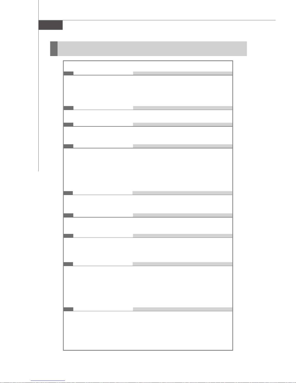
CONTENTS
Chapter 1 Getting Started....................................................................................1-1
Mainboard Specifications...................................................................................1-2
Mainboard Layout................................................................................................1-4
Packing Checklist.................................................................................................1-4
Chapter 2 Hardware Setup..................................................................................2-1
Quick Components Guide....................................................................................2-2
CPU (Central Processing Unit)............................................................................2-2
Introduction to LGA 775 CPU......................................................................2-3
CPU & Cooler Installation.............................................................................2-4
Memory.................................................................................................................2-7
Dual Channel Memory Population Rules....................................................2-7
Installing DDRII Modules...............................................................................2-8
Power Supply......................................................................................................2-8
ATX 24-Pin Power Connector: ATXPWR1.................................................2-9
ATX 12V Power Connector: JPW1............................................................2-9
Back Panel...........................................................................................................2-11
Connectors........................................................................................................2-12
Floppy Disk Drive Connector: FDD1..........................................................2-12
Hard Disk Connector: IDE1 (optional).......................................................2-12
Serial ATAII Connectors: SATA1~SATA6.................................................2-13
Fan Power Connectors: CPUFAN1, SYSFAN1 & PWRFAN1..................2-14
CD-In Connector: CD_IN1..........................................................................2-14
Chassis Intrusion Switch Connector: JCASE1.......................................2-14
Front Panel Audio Connector: JAUD1......................................................2-15
SPDIF-Out Connector: JSPD1 (Optional).................................................2-15
Front Panel Connectors: JFP1/JFP2........................................................2-16
Front USB Connectors: JUSB1, JUSB2, JUSB3 (JUSB1 is optional)....2-17
Serial Port Connector: JCOM1..................................................................2-17
IEEE 1394 Connectors: J1394_1 (Optional)............................................2-18
FWH/LPC Debugging Pin Header: JLPC1 (Optional)...............................2-18
JSPI Debugging Pin Header: JSPI1............................................................2-18
Jumpers..............................................................................................................2-18
Clear CMOS Jumper: JBAT1.....................................................................2-19
Slots....................................................................................................................2-20
PCI (Peripheral Component Interconnect) Express Slots......................2-20
PCI (Peripheral Component Interconnect) Slots......................................2-20
PCI Interrupt Request Routing...................................................................2-21
viii
Page 9

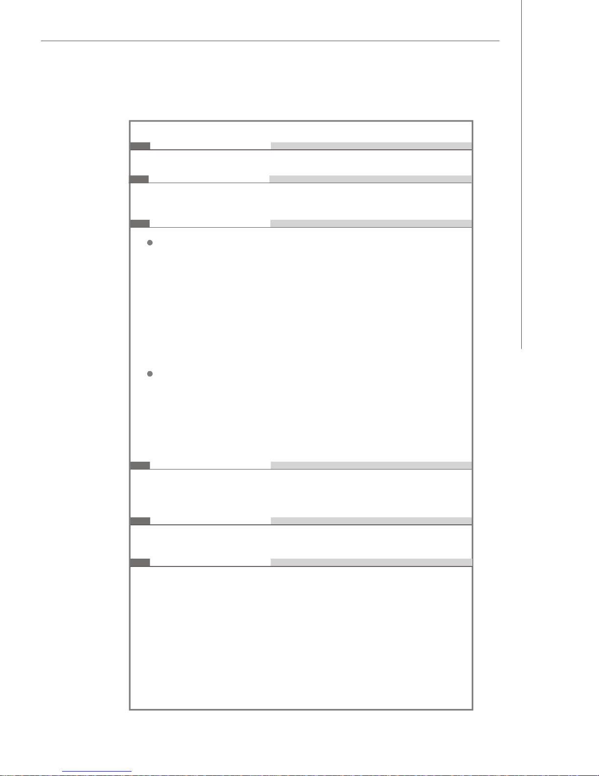
Chapter 3 BIOS Setup.............................................................................................3-1
Entering Setup.....................................................................................................3-2
The Main Menu.....................................................................................................3-4
Standard CMOS Features...................................................................................3-6
Advanced BIOS Features...................................................................................3-8
Advanced Chipset Features............................................................................3-10
Integrated Peripherals.......................................................................................3-12
Power Management Setup...............................................................................3-17
PNP/PCI Configurations.....................................................................................3-18
H/W Monitor........................................................................................................3-20
Load Optimized Defaults...................................................................................3-22
BIOS Setting Password.....................................................................................3-24
Appendix A Realtek ALC883 Audio....................................................................7-1
Installation for Windows 2000/XP......................................................................7-2
Installing the Realtek HD Audio Driver................................................................7-2
Software Configuration......................................................................................7-4
Sound Effect................................................................................................7-5
Mixer.............................................................................................................7-8
Audio I/O.....................................................................................................7-12
Microphone................................................................................................7-16
3D Audio Demo...........................................................................................7-17
Information..................................................................................................7-18
Hardware Setup................................................................................................7-19
Appendix B Intel ICH8R/DO/DH SATA RAID.........................................................7-1
ICH8R/DO/DH Introduction..................................................................................7-2
BIOS Configuration..............................................................................................7-2
Using the Intel Matrix Stroage Manager Option ROM...............................7-3
Installing Software..............................................................................................7-8
Install Driver in Windows XP / 2000...........................................................7-9
Installation of Intel Matrix Storage Console.............................................7-10
RAID Migration Instructions...............................................................................7-15
Create RAID Volume from Existing Disk...................................................7-15
Degraded RAID Array........................................................................................7-20
Missing Hard Drive Member......................................................................7-21
Failed Hard Drive Member.........................................................................7-21
ix
Page 10
Getting Started
Chapter 1
Getting Started
Thank you for choosing the G965MDH/Q965MDO Series (MS-7276 v1.X) Micro-ATX mainboard. The
G965MDH/Q965MDO Series mainboards are based on
Intel® G965/ Q965 & ICH8R / ICH8DO / ICH8DH chipsets
for optimal system efficiency. Designed to fit the advanced Intel® CoreTM 2 Duo, Pentium 4, Pentium D
and Celeron D processor, the G965MDH/Q965MDO
Series deliver a high performance and professional
desktop platform solution.
1-1
Page 11
MS-7276 Mainboard
Mainboard Specifications
Processor Support
- Intel® CoreTM 2 Duo, Pentium 4, Pentium D and Celeron D
processors in the LGA775 package.
For the latest information about CPU, please visit http://www.msi.
com.tw/program/products/mainboard/mbd/pro_mbd_cpu_support.php
Supported FSB
- 1066/ 800/ 533 MHz
Chipset
- North Bridge: Intel® G965/Q965 chipset
- South Bridge: Intel® ICH8R/ICH8DO/ICH8DH chipset (optional)
Memory Support
- DDRII 800/ 667/ 533 SDRAM
- 4 DDRII DIMMs (DDRII 800 supports up to 4 GB, DDRII 667/ 533
supports up to 8 GB, 240pin / 1.8V)
For the updated supporting memory modules, please visit
http://www.msi.com.tw/program/products/mainboard/mbd/
pro_mbd_trp_list.php
LAN
- Supports Gbe LAN by 82566 DM/DC (optional)
- Supports 10/100 LAN by 82562V (optional)
IEEE 1394 (optional)
- Chip integrated by VIA VT6308P or VT6307
- Transfer rate is up to 400Mbps
Audio
- Chip integrated by Realtek® ALC883 or ALC888
- Flexible 8-channel audio with jack sensing
- Compliant with Azalia 1.0 Spec
IDE (USB to IDE)
- 1 IDE port by JMicron JMB20335
- Supports USB to Ultra DMA 66 mode
Caution :
This IDE does not support OS installaion in hard drive.
A system hard drive connected to this IDE slot can not be booted up
to OS.
SATA
- 6 SATAII ports by ICH8R/DO/DH
- Supports storage and data transfers at up to 300 MB/s
1-2
Page 12
Getting Started
RAID
- SATA1~6 support RAID 0/ 1/ 5/ 10 mode by ICH8R/DO/DH
Floppy
- 1 floppy port
- Supports 1 FDD with 360K, 720K, 1.2M, 1.44M and 2.88Mbytes
Connectors
Back panel
- 1 PS/2 mouse port
- 1 PS/2 keyboard port.
- 1 Serial port
- 1 Parallel port supporting SPP/EPP/ECP mode
- 1 VGA Port
- 1 IEEE 1394 port (optional)
- 4 USB 2.0 Ports.
- 1 LAN jack
- 6 flexible audio jacks
On-Board Pinheaders
- 1 COM port pinheader
- 3 USB 2.0 pinheaders (JUSB1 is optional)
- 1 CD-IN pinheader
- 1 SPDIF-out pinheader (optional)
- 1 1394 pinheader (optional)
- 1 Front Audio pinheader
Slots
- 1 PCI Express x16 slot (for G965M/ Q965M series)
- 1 PCI Express x1 slot
- 2 PCI slots, support 3.3V/ 5V PCI bus Interface.
Form Factor
- Micro-ATX (24.4cm X 24.4cm)
Mounting
- 8 mounting holes
1-3
Page 13
MS-7276 Mainboard
JFP
2
JFP1J
B
A
T1JSPI1IDE
1FDD
1
DIM
M
_
A
1
DIM
M_B1DIM
M
_
A
2
DIM
M_B
2
ATX
PWR
1
J
CAS
E
1
JLP
C
1
Winbond
W83627DHG
JUSB2
JUSB3
JMicron
Jm20335
JCOM1
SATA6
SATA5
SATA4
SATA3
SATA2
SATA1
Intel
ICH8R/DO/DH
BATT
CD_IN1
(optional)
CPUFAN1
Line-In
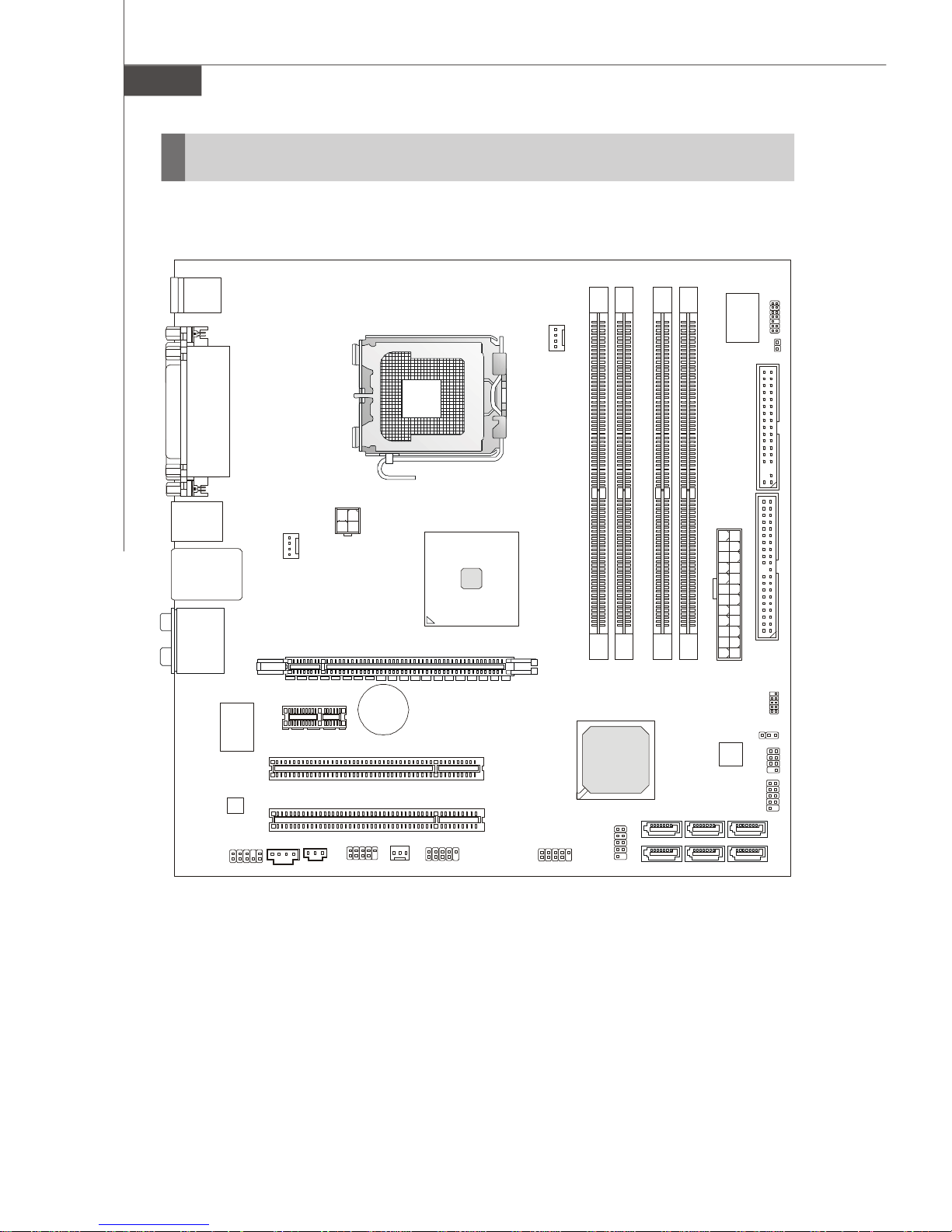
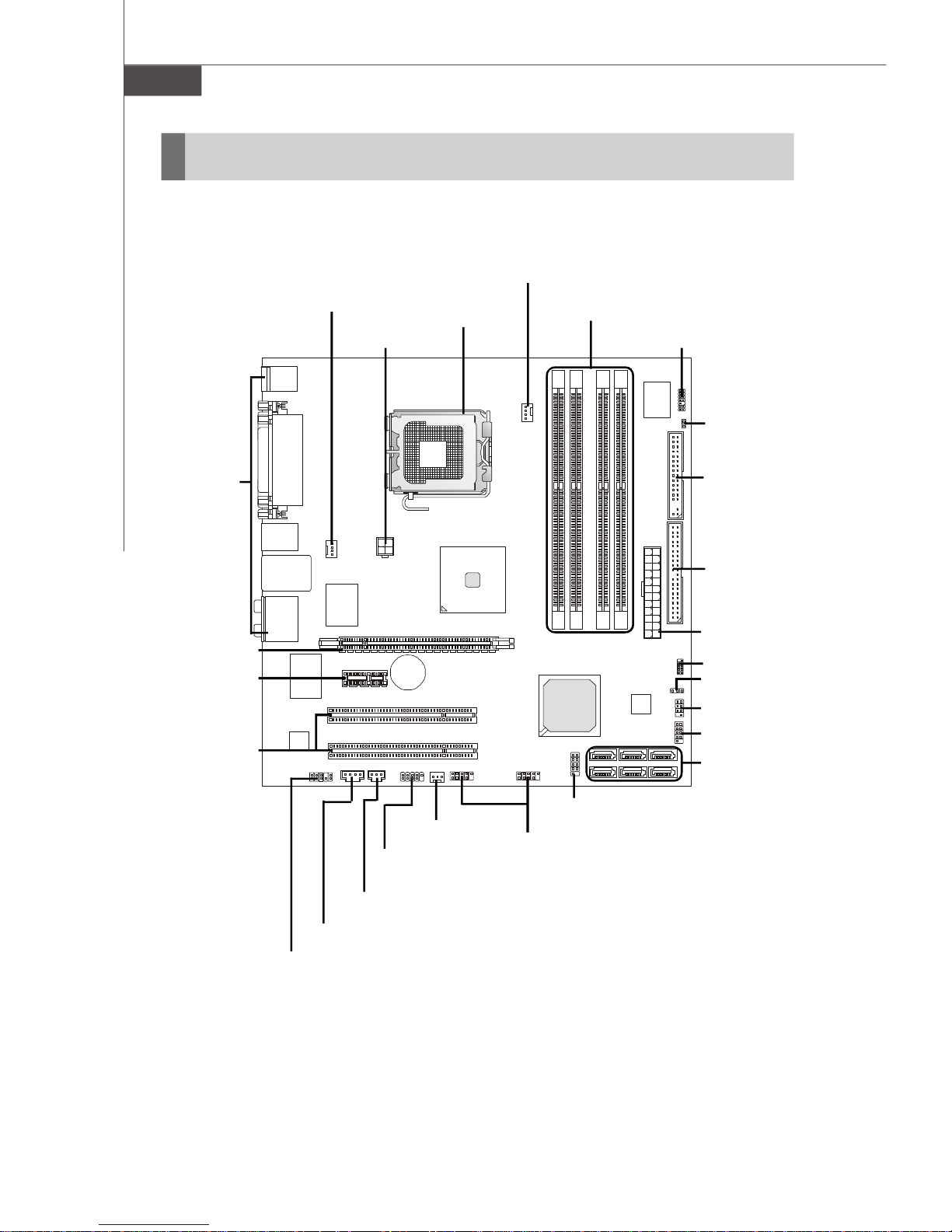
Mainboard Layout
Top : mouse
Bottom:
keyboard
Top :
Parallel Port
Bottom:
COM port
VGA port
Top:1394(optional)
Bottom: USB ports
Top: LAN Jack
Bottom: USB ports
T:
M:
Line-Out
B:
Mic
T:RS-Out
M:CS-Out
B:SS-Out
VIA
VT6307/
VT6308
ALC883
/ALC888
JAUD1
SYSFAN1
PCI E1
PCI E2
PCI 1
PCI 2
JSPD1
JPW1
J1394_1
+
PWRFAN1
Intel
G965/Q965
1-4
G965MDH/Q965MDO Series
(MS-7276 v1.X) Mainboard
Page 14
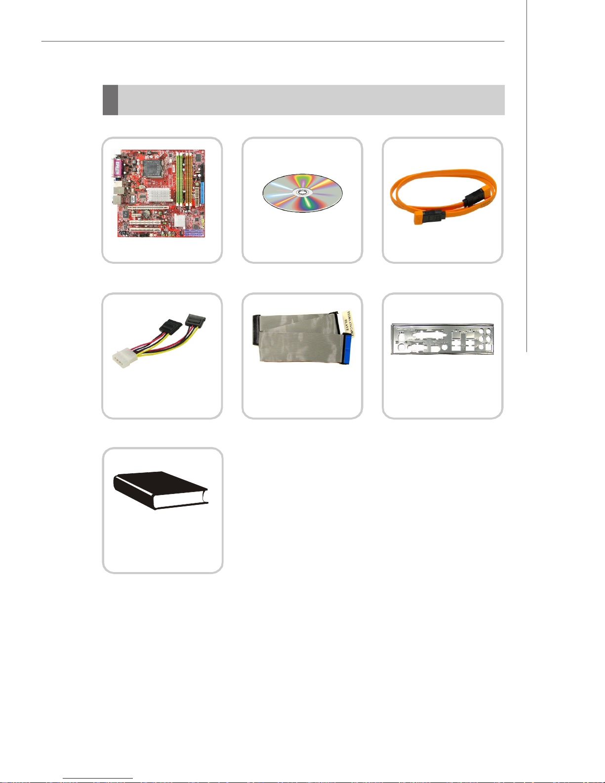
Packing Checklist
Getting Started
MSI motherboard
Power Cable
MSI Driver/Utility CD
Standard Cable for
IDE Devices
SATA Cable (Optional)
Back IO Shield
User’s Guide
* The pictures are for reference only. Your packing contents may vary depending on
the model you purchased.
1-5
Page 15

Hardware Setup
Chapter 2
Hardware Setup
This chapter provides you with the information about
hardware setup procedures. While doing the installation,
be careful in holding the components and follow the
installation procedures. For some components, if you
install in the wrong orientation, the components will not
work properly.
Use a grounded wrist strap before handling computer
components. Static electricity may damage the
components.
2-1
Page 16
MS-7276 Mainboard
Quick Components Guide
CPUFAN1, p.2-14
Back Panel,
p.2-10
PCIE x16
Slot, p.2-20
PCIE x1 Slot,
p.2-20
PCI Slots,
p.2-20
SYSFAN1, p.2-14
JPW1, p.2-9
CPU, p.2-3
DDRII DIMMs, p.2-7
JLPC1, p.2-18
JCI1, p.2-14
FDD1, p.2-12
IDE1, p.2-12
JPWR1, p.2-9
JSPI1, p.2-18
JBAT1, p.2-19
JFP2, p.2-16
JFP1, p.2-16
SATA1~6,
p.2-13
JCD1, p.2-14
JAUD1, p.2-15
2-2
PWRFAN1,
p.2-14
J1394_1 (optional),
p.2-18
JSPD1, p.2-15
JCOM1, p.2-17
JUSB2/3, p.2-17
Page 17
Hardware Setup
CPU (Central Processing Unit)
This mainboard supports Intel® CoreTM 2 Duo, Pentium 4, Pentium D, Celeron D processor in LGA 775 package. When you are installing the CPU, make sure to install the
cooler to prevent overheating. If you do not have the CPU cooler, contact your
dealer to purchase and install them before turning on the computer.
For the latest information about CPU, please visit http://www.msi.com.tw/program/
products/mainboard/mbd/pro_mbd_cpu_support.php
Important
1. Overheating will seriously damage the CPU and system. Always make
sure the cooling fan can work properly to protect the CPU from overheating.
2. Make sure that you apply an even layer of heat sink paste (or thermal tape)
between the CPU and the heatsink to enhance heat dissipation.
3. While replacing the CPU, always turn off the ATX power supply or unplug
the power supply’s power cord from the grounded outlet first to ensure the
safety of CPU.
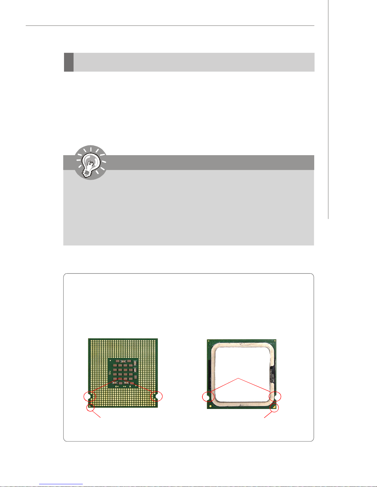
Introduction to LGA 775 CPU
The pin-pad side of LGA 775
CPU.
Alignment Key Alignment Key
Yellow triangle is the Pin 1 indicator
The surface of LGA 775 CPU.
Remember to apply some silicone
heat transfer compound on it for
better heat dispersion.
Yellow triangle is the Pin 1 indicator
2-3
Page 18
MS-7276 Mainboard
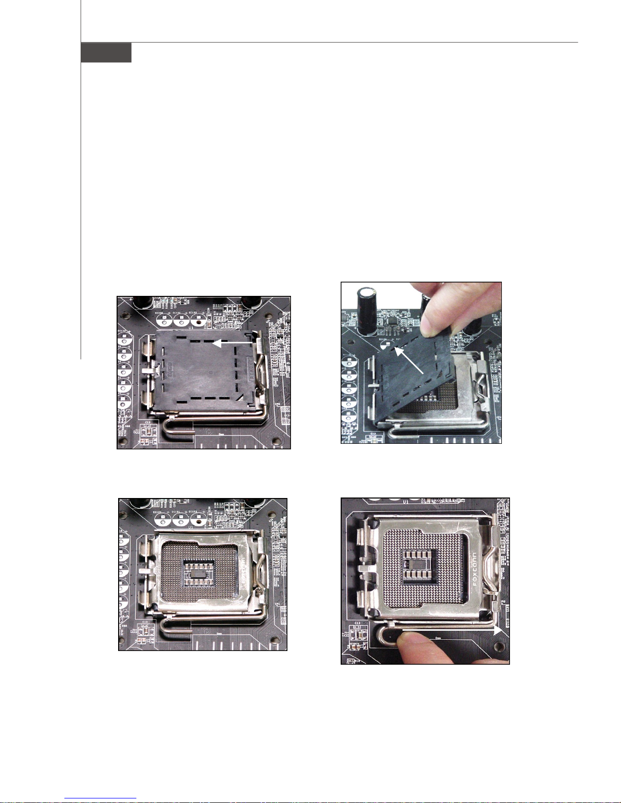
CPU & Cooler Installation
When you are installing the CPU, make sure the CPU has a cooler attached on
the top to prevent overheating. If you do not have the cooler, contact your dealer
to purchase and install them before turning on the computer. Meanwhile, do not forget
to apply some silicon heat transfer compound on CPU before installing the heat sink/
cooler fan for better heat dispersion.
Follow the steps below to install the CPU & cooler correctly. Wrong installation will
cause the damage of your CPU & mainboard.
1.The CPU has a plastic cap on it to
protect the contact from damage.
Before you install the CPU, always
cover it to protect the socket pin.
3.The pins of socket reveal.
2.Remove the cap from lever hinge
side (as the arrow shows).
4.Open the load lever.
2-4
Page 19
Hardware Setup
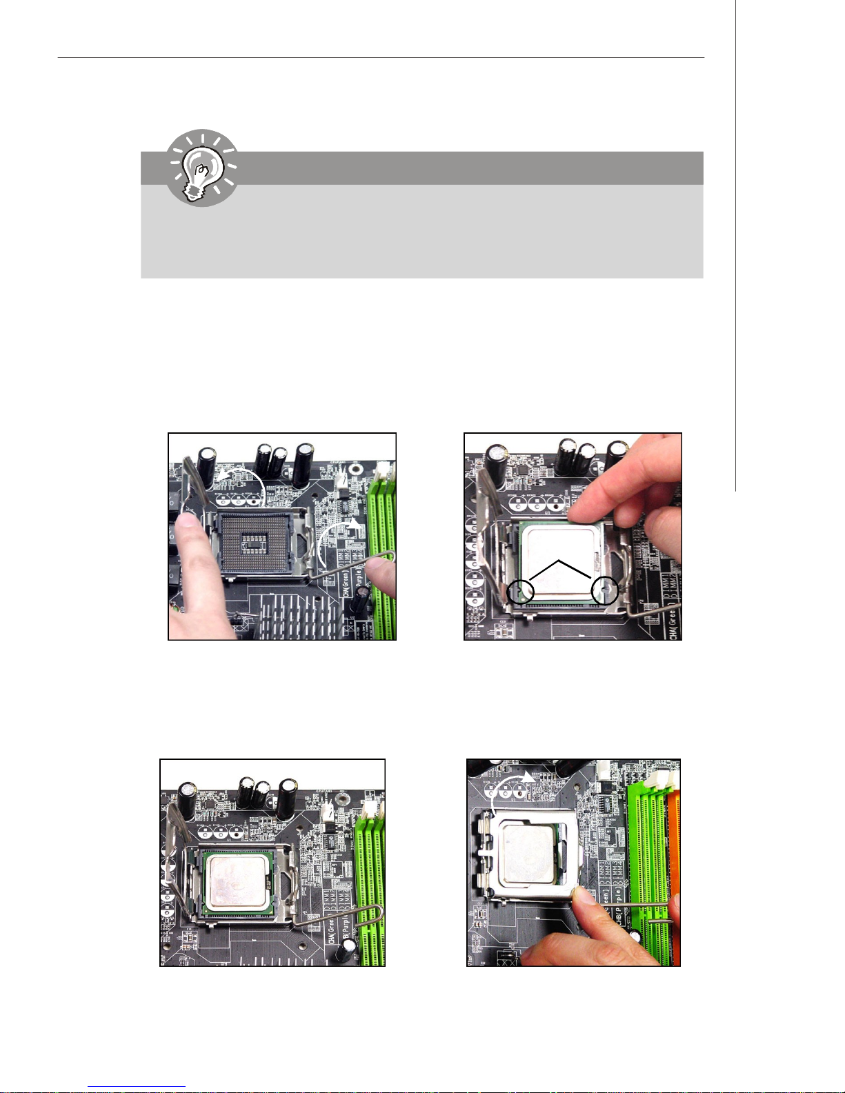
Important
1.Confirm if your CPU cooler is firmly installed before turning on your system.
2. Do not touch the CPU socket pins to avoid damaging.
3. The availability of the CPU land side cover depends on your CPU packing.
5.Lift the load lever up and open the
load plate.
7.Visually inspect if the CPU is
seated well into the socket. If not,
take out the CPU with pure vertical
motion and reinstall.
6.After confirming the CPU direction
for correct mating, put down the
CPU in the socket housing frame.
Be sure to grasp on the edge of
the CPU base. Note that the alignment keys are matched.
alignment
key
8.Cover the load plate onto the
package.
2-5
Page 20
MS-7276 Mainboard
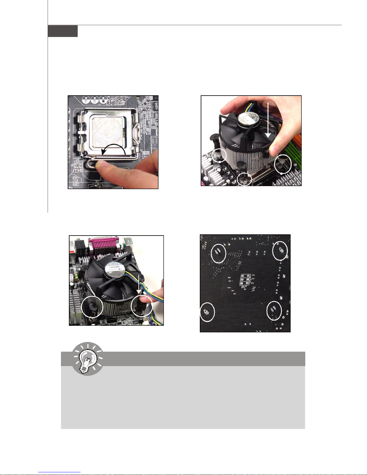
9.Press down the load lever lightly
onto the load plate, and then secure the lever with the hook under
retention tab.
11.Press the four hooks down to fas-
ten the cooler. Then rotate the locking switch (refer to the correct direction marked on it) to lock the
hooks.
10. Align the holes on the mainboard
with the heatsink. Push down the
cooler until its four clips get
wedged into the holes of the
mainboard.
12.Turn over the mainboard to confirm that the clip-ends are correctly inserted.
locking
switch
Important
1.Check the information in BIOS (Chapter 3) for the CPU temperature.
2. Whenever CPU is not installed, always protect your CPU socket pin with the
plastic cap covered (shown in Figure 1) to avoid damaging.
3. Please note that the mating/unmating durability of the CPU is 20 cycles.
Therefore we suggest you do not plug/unplug the CPU too often.
2-6
Page 21
Hardware Setup
1
2
3
Memory
he mainboard provides four 240-pin non-ECC DDRII 800/ 667/ 533 DIMM slots.
For more information on compatible components, please visit http://www.msi.com.tw/
program/products/mainboard/mbd/pro_mbd_trp_list.php
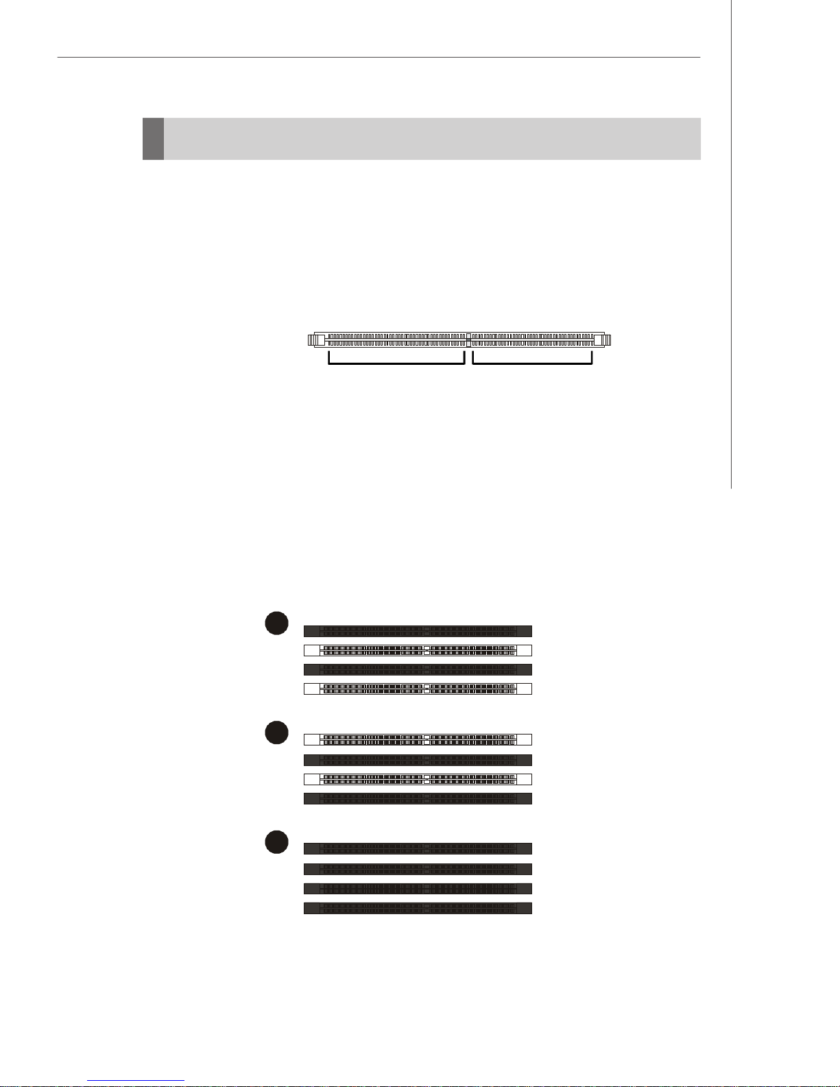
DDRII
240-pin, 1.8V
64x2=128 pin 56x2=112 pin
Dual-Channel: Channel A in GREEN; Channel B in ORANGE
Dual Channel Memory Population Rules
DIMM_A1
DIMM_A2
DIMM_B1
DIMM_B2
DIMM_A1
DIMM_A2
DIMM_B1
DIMM_B2
DIMM_A1
DIMM_A2
DIMM_B1
DIMM_B2
2-7
Page 22
MS-7276 Mainboard
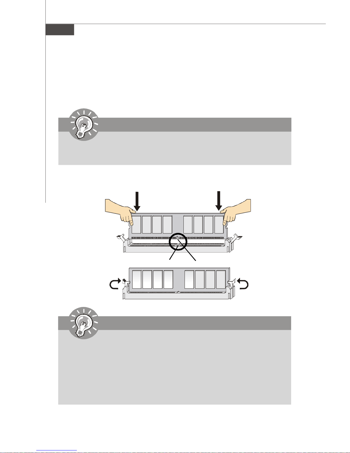
Installing DDRII Modules
1. The memory module has only one notch on the center and will only fit in the right
orientation.
2. Insert the memory module vertically into the DIMM slot. Then push it in until the
golden finger on the memory module is deeply inserted in the DIMM slot.
Important
You can barely see the golden finger if the module is properly inserted in the
DIMM slot.
3. The plastic clip at each side of the DIMM slot will automatically close.
Volt
Notch
Important
-DDRII modules are not interchangeable with DDR and the DDRII standard is
not backwards compatible. You should always install DDRII memory modules in the DDRII DIMM slots and DDR memory modules in the DDR DIMM
slots.
-In dual-channel mode, make sure that you install memory modules of the
same type and density in differentchannel DDR DIMM slots.
-To enable successful system boot-up, always insert the memory modules
into the DIMM_A1 first.
2-8
Page 23
Hardware Setup
Power Supply
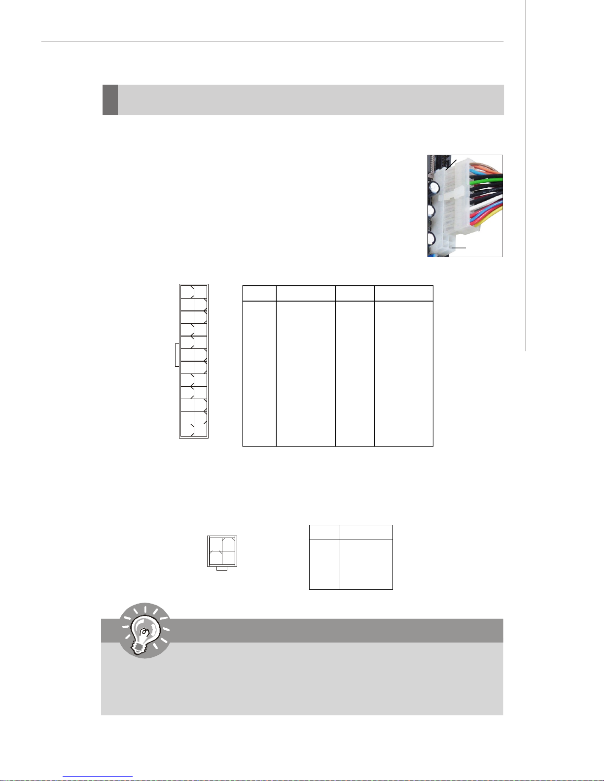
ATX 24-Pin Power Connector: ATXPWR1
This connector allows you to connect an ATX 24-pin power supply.
To connect the ATX 24-pin power supply, make sure the plug of the
power supply is inserted in the proper orientation and the pins are
aligned. Then push down the power supply firmly into the connector.
You may use the 20-pin ATX power supply as you like. If you’d like
to use the 20-pin ATX power supply, please plug your power supply along with pin 1 & pin 13 (refer to the image at the right hand).
There is also a foolproof design on pin 11, 12, 23 & 24 to avoid
wrong installation.
Pin Definition
13
ATXPWR1
24
1
12
PIN SIGNAL
1 +3.3V
2 +3.3V
3 GND
4 +5V
5 GND
6 +5V
7 GND
8 PWR OK
9 5VSB
10 +12V
11 +12V
12 +3.3V
PIN SIGNAL
13 +3.3V
14 -12V
15 GND
16 PS-ON#
17 GND
18 GND
19 GND
20 Res
21 +5V
22 +5V
23 +5V
24 GND
pin 13
pin 12
ATX 12V Power Connector: JPW1
This 12V power connector is used to provide power to the CPU.
Pin Definition
JPW1
2
1
34
PIN SIGNAL
1 GND
2 GND
3 12V
4 12V
Important
1. Maker sure that all the connectors are connected to proper ATX power supplies to ensure stable operation of the mainboard.
2. Power supply of 450 watts (and above) is highly recommended for system
stability.
2-9
Page 24
MS-7276 Mainboard
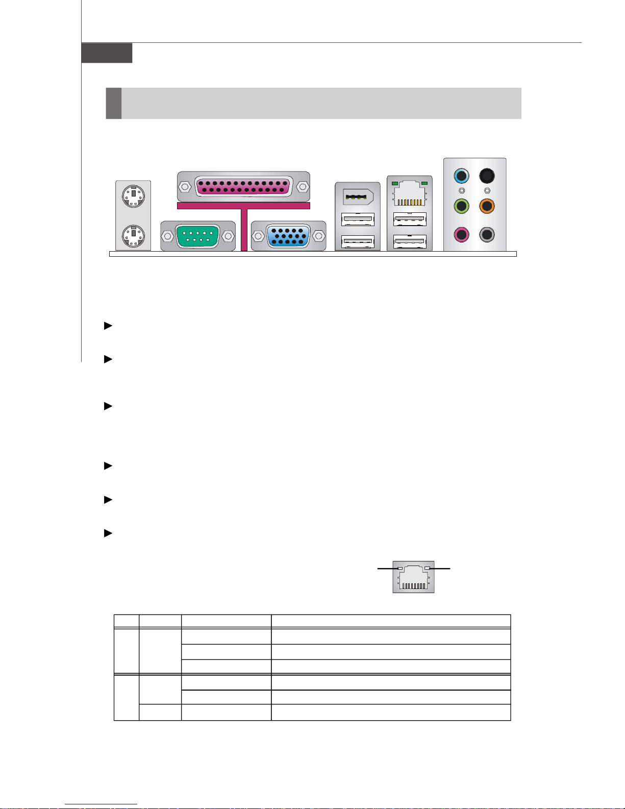
Back Panel
Mouse
Parallel Port
IEEE1394
Port (optional)
LAN
L-In
RS-Out
Keyboard
Serial Port
VGA Port
USB Ports
L-Out
Mic
CS-Out
SS-Out
Mouse/Keyboard Connector
The standard PS/2® mouse/keyboard DIN connector is for a PS/2® mouse/keyboard.
Parallel Port Connector
A parallel port is a standard printer port that supports Enhanced Parallel Port (EPP)
and Extended Capabilities Parallel Port (ECP) mode.
Serial Port Connector
The serial port is a 16550A high speed communications port that sends/ receives 16
bytes FIFOs. You can attach a serial mouse or other serial devices directly to the
connector.
VGA Connector
The DB15-pin female connector is provided for VGA monitors.
IEEE 1394 Port (optional)
The 1394 port on the back panel provides connection to 1394 devices.
LAN (RJ-45) Jack
The standard RJ-45 jack is for connection to single Local Area Network (LAN).
You can connect a network cable to it.
Link IndicatorActivity Indicator
LED Color LED State condition
Off LAN link is not established.
Left Orange On (steady state) LAN link is established.
On (blinking) The computer is communicating with another computer on the LAN.
Green Off 10 Mbit/sec data rate is selected.
Right On 100 Mbit/sec data rate is selected.
Orange On 1000 Mbit/sec data rate is selected.
2-10
Page 25

Hardware Setup
USB Connectors
The OHCI (Open Host Controller Interface) Universal Serial Bus root is for attaching
USB devices such as keyboard, mouse, or other USB-compatible devices.
Audio Port Connectors
These audio connectors are used for audio devices. You can differentiate the color
of the audio jacks for different audio sound effects.
Blue audio jack - Line In, is used for external CD player, tapeplayer or
other audio devices.
Green audio jack - Line Out, is a connector for speakers or headphones.
Pink audio jack - Mic In, is a connector for microphones.
Black audio jack - Rear-Surround Out in 4-/ 5.1/ 7.1 channel mode.
Orange audio jack - Center/ Subwoofer Out in 5.1/ 7.1 channel mode.
Gray audio jack - Side-Surround Out in 7.1 channel mode.
2-11
Page 26

MS-7276 Mainboard
Connectors
Floppy Disk Drive Connector: FDD1
This standard FDD connector supports 360K, 720K, 1.2M, 1.44M and 2.88M floppy
disk types.
FDD1
Hard Disk Connector: IDE1 (optional)
The mainboard provides a USB to IDE connector that supports Ultra DMA 66 function.
You can connect hard disk drives, CD-ROM drives and other IDE devices.
Note: Due to Full Speed USB bandwidth is limited to 480Mb/s (60MB/s), this
IDE port can not support Ultra DMA 100 interface devices.
IDE1
IDE can connect a Master and a Slave drive. You must configure the second hard drive to Slave mode by setting the jumper
accordingly.
Important
- If you install two hard disks on cable, you must configure the second drive
to Slave mode by setting its jumper. Refer to the hard disk documentation
supplied by hard disk vendors for jumper setting instruction.
- A hard drive connected to this IDE connector does not support OS
installation. Furthermore, a system hard drive connected to this IDE con nector can not be booted up to OS. We strongly recommend you install the
Optical Disk Drive device to this IDE connector.
2-12
Page 27
Hardware Setup
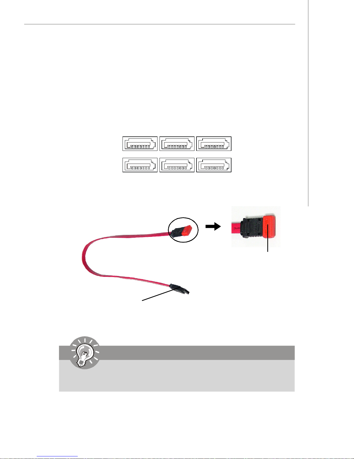
Serial ATAII Connectors: SATA1~SATA6
SATA1~SATA6 are high-speed Serial ATA interface ports. Each supports 2nd generation serial ATA data rates of 300MB/s and is fully compliant with Serial ATA 2.0
specifications. Each Serial ATA connector can connect to 1 hard disk device.
SATA5 SATA3 SATA1
SATA6
Serial ATA cable
Connect to SATA Ports
SATA4
(for ICH8R/
DO/DH)
SATA2
(for ICH8R/
DO/DH)
Take out the dust cover
and connect to the hard
disk devices
Important
Please do not fold the Serial ATA cable into 90-degree angle. Otherwise,
data loss may occur during transmission.
2-13
Page 28
MS-7276 Mainboard
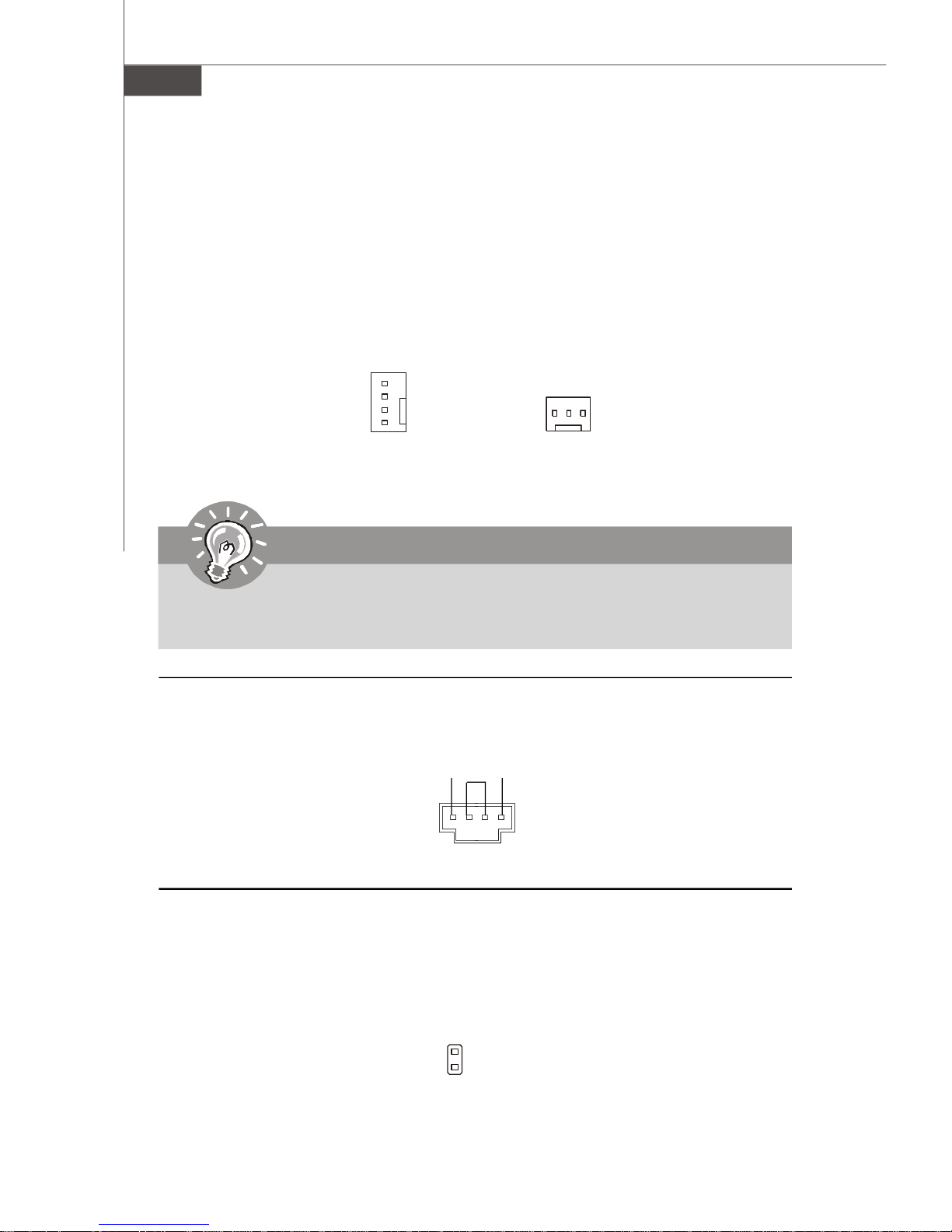
Fan Power Connectors: CPUFAN1, SYSFAN1 & PWRFAN1
The fan power connectors support system cooling fan with +12V. When connecting
the wire to the connectors, always take note that the red wire is the positive and
should be connected to the +12V, the black wire is Ground and should be connected
to GND. If the mainboard has a System Hardware Monitor chipset on-board, you must
use a specially designed fan with speed sensor to take advantage of the CPU fan
control.
CONTROL
SENSOR
+12V
GND
CPUFAN1/SYSFAN1
+12V
GND
PWRFAN1
NC
Important
Please refer to the recommended CPU fans at Intel® official website or consult
the vendors for proper CPU cooling fan.
CD-In Connector: CD_IN1
This connector is provided for CD-ROM audio.
GNDL R
CD_IN1
Chassis Intrusion Switch Connector: JCASE1
This connector connects to a 2-pin chassis switch. If the chassis is opened, the
switch will be short and the buzzer will sound the alarm. The system will record this
status and show a warning message on the screen. To clear the warning, you must
enter the BIOS utility and clear the record.
2-14
CINTRU
GND
1
JCASE1
Page 29
Hardware Setup
Front Panel Audio Connector: JAUD1
The JAUD1 front panel audio connector allows you to connect the front panel audio
and is compliant with Intel® Front Panel I/O Connectivity Design Guide.
2
1
10
9
JAUD1
JAUD1 Pin Definition
PIN SIGNAL DESCRIPTION
1 AUD_MIC Front panel microphone input signal
2 AUD_GND Ground used by analog audio circuits
3 AUD_MIC_BIAS Microphone power
4 AUD_VCC Filtered +5V used by analog audio circuits
5 AUD_FPOUT_R Right channel audio signal to front panel
6 AUD_RET_R Right channel audio signal return from front panel
7 HP_ON Reserved for future use to control headphone amplifier
8 KEY No pin
9 AUD_FPOUT_L Left channel audio signal to front panel
10 AUD_RET_L Left channel audio signal return from front panel
SPDIF-Out Connector: JSPD1 (Optional)
This connector is used to connect SPDIF (Sony & Philips Digital Interconnect Format)
interface for digital audio transmission.
GND
JSPD1
VCC
SPDIF
2-15
Page 30
MS-7276 Mainboard
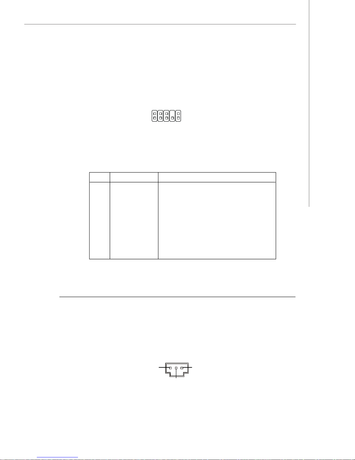
Front Panel Connectors: JFP1/JFP2
The mainboard provides two front panel connectors for electrical connection to the
front panel switches and LEDs. The JFP1 is compliant with Intel® Front Panel I/O
Connectivity Design Guide.
JFP2
12
+
-
78
HDD
LED
Reset
Switch
+
-
+
9
JFP1
1
2
10
Power
LED
+
Power
Switch
-
Power
LED
JFP1 Pin Definition
PIN SIGNAL DESCRIPTION
1 HD_LED + Hard disk LED +
2 PWR/SLP LED Power LED+/ Suspend LED
3 HD_LED - Hard disk LED-
4 PWR/SLP LED Power LED-/ Suspend LED
5 RST_SW Reset Switch
6 PWR_SW Power Switch
7 RST_SW Reset Switch
8 PWR_SW Power Switch
9 N.C. Not Connected
10 Key Key (no pin)
-
Speaker
+
PIN SIGNAL DESCRIPTION
1 GND Ground (LED-)
2 SPK Speaker
3 SLP LED Suspend LED+
4 BUZ Buzzer
5 PWR LED Power LED+
6 BUZ Buzzer
7 Key Key (no pin)
8 SPK Speaker
2-16
JFP2 Pin Definition
Page 31

Hardware Setup
Front USB Connectors: JUSB1, JUSB2, JUSB3 (JUSB1 is optional)
The mainboard provides USB 2.0 pinheaders (optional USB 2.0 bracket available) that
are compliant with Intel® I/O Connectivity Design Guide. USB 2.0 technology increases
data transfer rate up to a maximum throughput of 480Mbps, which is 40 times faster
than USB 1.1, and is ideal for connecting high-speed USB interface peripherals such
as USB HDD, digital cameras, MP3 players, printers, modems and the like.
Pin Definition
JUSB1/2/3
2
1
10
9
PIN SIGNAL PIN SIGNAL
1 VCC 2 VCC
3 USB0- 4 USB1-
5 USB0+ 6 USB1+
7 GND 8 GND
9 Key (no pin) 10 N.C.
Important
Note that the pins of VCC and GND must be connected correctly to avoid
possible damage.
Serial Port Connector: JCOM1
The mainboard provides one 9-pin header as serial port JCOM1. The port is a 16550A
high speed communication port that sends/receives 16 bytes FIFOs. You can attach
a serial mouse or other serial devices directly to it.
Pin Definition
PIN SIGNAL DESCRIPTION
JCOM1
192
1 DCD Data Carry Detect
2 SIN Serial In or Receive Data
3 SOUT Serial Out or Transmit Data
4 DTR Data Terminal Ready
5 GND Ground
6 DSR Data Set Ready
7 RTS Request To Send
8 CTS Clear To Send
9 RI Ring Indicate
2-17
Page 32

MS-7276 Mainboard
IEEE 1394 Connectors: J1394_1 (Optional)
The mainboard provides IEEE1394 pinheaders that allow you to connect IEEE 1394
ports via an external IEEE1394 bracket (optional).
Pin Definition
PIN SIGNAL PIN SIGNAL
2
1
10
9
J1394_1
1 TPA+ 2 TPA-
3 Ground 4 Ground
5 TPB+ 6 TPB-
7 Cable power 8 Cable power
9 Key (no pin) 10 Ground
FWH/LPC Debugging Pin Header: JLPC1 (Optional)
The pin header is for internal debugging only.
JLPC1
13
21
14
PIN SIGNAL PIN SIGNAL
1 LCLK 2 Key (no pin)
3 LRST# 4 VCC3
5 LAD0 6 FID0_LRST
7 LAD1 8 VCC5
9 LAD2 10 Key (no pin)
11 LAD3 12 GND
13 LFRAME# 14 GND
JSPI Debugging Pin Header: JSPI1
The pin header is for internal debugging only.
JSPI1
2
910
1
PIN SIGNAL PIN SIGNAL
1 VCC3_SB 2 VCC3_SB
3 SPI_MISO 4 SPI_MOSI_F
5 SPI_CSO_F# 6 SPI_CLK_F
7 GND 8 GND
9 Reserved 10 NC
JLPC1 Pin Definition
JSPI1 Pin Definition
2-18
Page 33

Hardware Setup
Jumpers
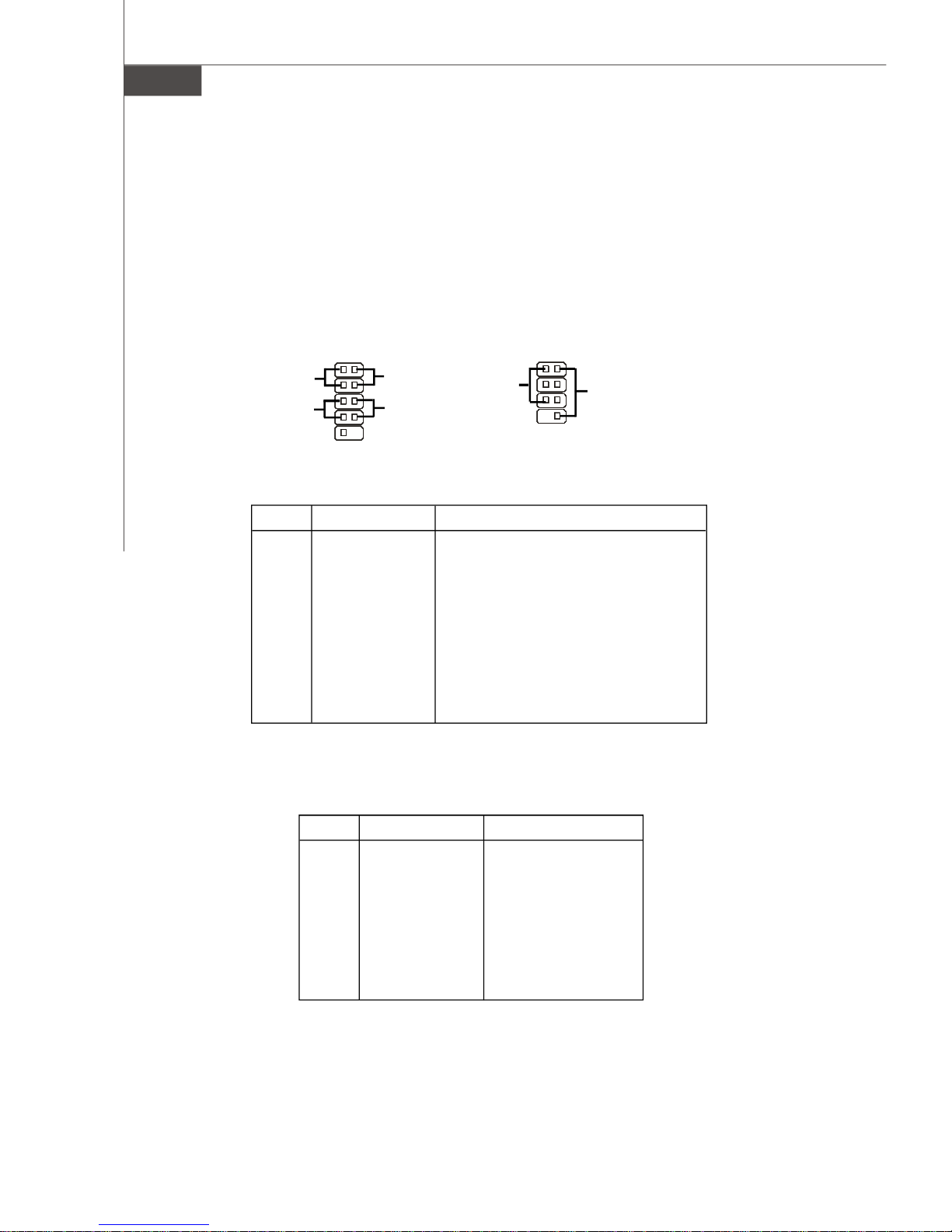
Clear CMOS Jumper: JBAT1
There is a CMOS RAM onboard that has a power supply from external battery to keep
the data of system configuration. With the CMOS RAM, the system can automatically
boot OS every time it is turned on. If you want to clear the system configuration, set
the JBAT1 (Clear CMOS Jumper ) to clear data.
1
Clear Data
3
1
JBAT1
1 3
Keep Data
Important
You can clear CMOS by shorting 2-3 pin while the system is off. Then return
to 1-2 pin position. Avoid clearing the CMOS while the system is on; it will
damage the mainboard.
2-19
Page 34

MS-7276 Mainboard
Slots
PCI (Peripheral Component Interconnect) Express Slots
PCI Express architecture provides a high performance I/O infrastructure for Desktop
Platforms with transfer rates starting at 2.5 Giga transfers per second over a PCI
Express x1 lane for Gigabit Ethernet, TV Tuners, 1394 controllers, and general purpose I/O. Also, desktop platforms with PCI Express Architecture will be designed to
deliver highest performance in video, graphics, multimedia and other sophisticated
applications. Moreover, PCI Express architecture provides a high performance graphics
infrastructure for Desktop Platforms doubling the capability of existing AGP 8x designs with transfer rates of 4.0 GB/s over a PCI Express x16 lane for graphics
controllers, while PCI Express x1 supports transfer rate of 250 MB/s.
PCI Express x16 Slot
PCI Express x1 Slot
PCI (Peripheral Component Interconnect) Slots
The PCI slots support LAN cards, SCSI cards, USB cards, and other add-on cards
that comply with PCI specifications. At 32 bits and 33 MHz, it yields a throughput rate
of 133 MBps.
32-bit PCI Slot
Important
When adding or removing expansion cards, make sure that you unplug the
power supply first. Meanwhile, read the documentation for the expansion card
to configure any necessary hardware or software settings for the expansion
card, such as jumpers, switches or BIOS configuration.
2-20
Page 35

Hardware Setup
PCI Interrupt Request Routing
The IRQ, acronym of interrupt request line and pronounced I-R-Q, are hardware lines
over which devices can send interrupt signals to the microprocessor. The PCI IRQ
pins are typically connected to the PCI bus pins as follows:
Order 1 Order 2 Order 3 Order 4
PCI Slot 1 INT A# INT B# INT C# INT D#
PCI Slot 2 INT B# INTC# INT D# INT A#
2-21
Page 36

BIOS Setup
Chapter 3
BIOS Setup
This chapter provides information on the BIOS Setup
program and allows you to configure the system for
optimum use.
You may need to run the Setup program when:
² An error message appears on the screen during the
system booting up, and requests you to run SETUP.
² You want to change the default settings for cus-
tomized features.
3-1
Page 37

MS-7276 Mainboard
Entering Setup
Power on the computer and the system will start POST (Power On Self Test) process.
When the message below appears on the screen, press <DEL> key to enter Setup.
Press DEL to enter SETUP
If the message disappears before you respond and you still wish to enter Setup,
restart the system by turning it OFF and On or pressing the RESET button. You may
also restart the system by simultaneously pressing <Ctrl>, <Alt>, and <Delete> keys.
Important
1.The items under each BIOS category described in this chapter are under
continuous update for better system performance. Therefore, the description may be slightly different from the latest BIOS and should be held for
reference only.
2.Upon boot-up, the 1st line appearing after the memory count is the BIOS
version. It is usually in the format:
A7276IMS V1.0 081006 where:
1st digit refers to BIOS maker as A = AMI, W = AWARD, and P =
PHOENIX.
2nd - 5th digit refers to the model number.
6th digit refers to the chipset as I = Intel, N = nVidia, and V = VIA.
7th - 8th digit refers to the customer as MS = all standard customers.
V1.0 refers to the BIOS version.
081006 refers to the date this BIOS was released.
3-2
Page 38

Control Keys
<↑> Move to the previous item
<↓> Move to the next item
<←> Move to the item in the left hand
<→> Move to the item in the right hand
<Enter> Select the item
<Esc> Jumps to the Exit menu or returns to the main menu from a
<+/PU> Increase the numeric value or make changes
<-/PD> Decrease the numeric value or make changes
<F1> General Help
<F6> Load Optimized Defaults
<F7> Load Fail-safe Defaults
<F10> Save all the CMOS changes and exit
BIOS Setup
submenu
Getting Help
After entering the Setup menu, the first menu you will see is the Main Menu.
Main Menu
The main menu lists the setup functions you can make changes to. You can use the
arrow keys ( ↑↓ ) to select the item. The on-line description of the highlighted setup
function is displayed at the bottom of the screen.
Sub-Menu
If you find a right pointer symbol (as shown in the right
view) appears to the left of certain fields that means a
sub-menu can be launched from this field. A sub-menu
contains additional options for a field parameter. You
can use arrow keys ( ↑↓ ) to highlight the field and press <Enter> to call up the sub-
menu. Then you can use the control keys to enter values and move from field to field
within a sub-menu. If you want to return to the main menu, just press the <Esc >.
General Help <F1>
The BIOS setup program provides a General Help screen. You can call up this screen
from any menu by simply pressing <F1>. The Help screen lists the appropriate keys
to use and the possible selections for the highlighted item. Press <Esc> to exit the
Help screen.
3-3
Page 39

MS-7276 Mainboard
The Main Menu
Standard CMOS Features
Use this menu for basic system configurations, such as time, date etc.
Advanced BIOS Features
Use this menu to setup the items of AMI® special enhanced features.
Advanced Chipset Features
Use this menu to change the values in the chipset registers and optimize your system’s
performance.
Integrated Peripherals
Use this menu to specify your settings for integrated peripherals.
Power Management Features
Use this menu to specify your settings for power management.
PNP/PCI Configurations
This entry appears if your system supports PnP/PCI.
H/W Monitor
This entry shows your PC health status.
Load Optimized Defaults
Use this menu to load the default values set by the mainboard manufacturer specifically for optimal performance of the mainboard.
3-4
Page 40

BIOS Setting Password
Use this menu to set the password for BIOS.
Save & Exit Setup
Save changes to CMOS and exit setup.
Exit Without Saving
Abandon all changes and exit setup.
BIOS Setup
3-5
Page 41

MS-7276 Mainboard
Standard CMOS Features
The items in Standard CMOS Features Menu includes some basic setup items. Use
the arrow keys to highlight the item and then use the <PgUp> or <PgDn> keys to select
the value you want in each item.
Date (MM:DD:YY)
This allows you to set the system to the date that you want (usually the current date).
The format is <day><month> <date> <year>.
day Day of the week, from Sun to Sat, determined by
BIOS. Read-only.
month The month from Jan. through Dec.
date The date from 1 to 31 can be keyed by numeric function keys.
year The year can be adjusted by users.
Time (HH:MM:SS)
This allows you to set the system time that you want (usually the current time). The
time format is <hour> <minute> <second>.
Primary/Secondary/Third/Fourth IDE Master/ Slave
Press <Enter> to enter the sub-menu, and the following screen appears.
3-6
Page 42

BIOS Setup
Device/ Vender/ Size
It will showing the device information that you connected to the IDE/SATA connector .
LBA/Large Mode
This allows you to enable or disable the LBA Mode. Setting to Auto enables LBA
mode if the device supports it and the devices is not already formatted with LBA
mode disabled.
DMA Mode
Select DMA Mode.
Hard Disk S.M.A.R.T.
This allows you to activate the S.M.A.R.T. (Self-Monitoring Analysis & Reporting
Technology) capability for the hard disks. S.M.A.R.T is a utility that monitors your
disk status to predict hard disk failure. This gives you an opportunity to move
data from a hard disk that is going to fail to a safe place before the hard disk
becomes offline.
Important
Primary/Secondary/Third IDE Master/ Slave are appearing when you
connect the HD devices to the SATA connector on the mainboard.
Floppy Drive A
This item allows you to set the type of floppy drives installed. Available options:
[None], [360K, 5.25 in.], [1.2M, 5.25 in.], [720K, 3.5 in.], [1.44M, 3.5 in.], [2.88M, 3.5 in.].
Halt On Keyboard Error
The setting determines whether the system will stop if an error is detected at boot.
Available options are:
[No Errors] The system doesn’t stop for any detected error.
[All, But Keyboard] The system doesn’t stop for a keyboard error.
3-7
Page 43

MS-7276 Mainboard
System Information
Press <Enter> to enter the sub-menu, and the following screen appears.
This sub-menu shows the CPU information, BIOS version and memory status of your
system (read only).
3-8
Page 44

Advanced BIOS Features
BIOS Setup
Quick Boot
Setting the item to [Enabled] allows the system to boot within 10 seconds since it will
skip some check items.
Boot to OS/2
This allows you to run the OS/2® operating system with DRAM larger than 64MB.
When you choose [No], you cannot run the OS/2® operating system with DRAM larger
than 64MB. But it is possible if you choose [Yes].
Boot Sector Protection
This item allows you to choose the virus warning feature for Hard Disk boot sector
protection. If this function is enabled and someone attempt to write date into this area,
BIOS will shows a warning message on screen and alarm beep.
Hyper-Threading Function
The processor uses Hyper-Threading technology to increase transaction rates and
reduces end-user response times. The technology treats the two cores inside the
processor as two logical processors that can execute instructions simultaneously.
In this way, the system performance is highly improved. If you disable the function,
the processor will use only one core to execute the instructions. Please disable
this item if your operating system doesn’t support HT Function, or
unreliability and instability may occur.
3-9
Page 45

MS-7276 Mainboard
Important
Enabling the functionality of Hyper-Threading Technology for your computer
system requires ALL of the following platform Components:
* CPU: An Intel® Pentium® 4 Processor with HT Technology;
* Chipset: An Intel® Chipset that supports HT Technology;
* BIOS: A BIOS that supports HT Technology and has it enabled;
* OS: An operating system that supports HT Technology.
For more information on Hyper-threading Technology, go to:
www.intel.com/info/hyperthreading
Hardware Prefetcher:
Enable this item will improve the performance of CPU. It is only available with P4 CPU
installed.
IOAPIC Function
This field is used to enable or disable the APIC (Advanced Programmable Interrupt
Controller). Due to compliance with PC2001 design guide, the system is able to run in
APIC mode. Enabling APIC mode will expand available IRQ resources for the system.
Boot Sequence
Press <Enter> to enter the sub-menu:
1st/2nd/3rd Boot Device & Boot From Other Device
The items allow you to set the sequence of boot devices where BIOS attempts
to load the disk operating system.
Intel AMT Configuration (optional, only for ICH8DO)
Press <Enter> to enter the sub-menu:
Intel AMT Support
The items allow you to enable/disable the AMT (Active Management Technology)
support.
Force IDER
IDER (IDE redirection) enables the ability to boot system from a network location.
Trusted Computing
Press <Enter> to enter the sub-menu:
TCG/TPM SUPPORT
The items allow you to enable/disable the TPM (Trusted Platform Module) (1.1/1.
2) support.
3-10
Page 46

Advanced Chipset Features
BIOS Setup
Configure DRAM Timing by SPD
The system board designer must select the proper value for this field, according to
the specifications of the installed DRAM chips. When Disabled, you can select the
DRAM timing type.
Memory Hole
In order to improve performance, certain space in memory can be reserved for ISA
peripherals. This memory must be mapped into the memory space below 16MB. When
this area is reserved, it cannot be cached.
Memory Remap Feature
This field allows you to remap the memory which as PCI resources.
Internal Graphics Select
The field specifies the size of system memory allocated for video memory.
DVMT Mode Select
The field allows you to select the DVMT mode. Dynamic Video Memory Technology 3.
0 (DVMT 3.0) allows additional memory to be allocated for graphics usage based on
application need.
DVMT/ FIXED Memory
The field specifies the size of system memory allocated for video memory. “Fixed”
mode is non-contiguous pagelocked memory allocated during driver initialization to
provide a static amount of memory.“DVMT” mode is memory that is dynamically allocated based on memory requests made by application and are release back to the
system once the requesting application has been terminated.
3-11
Page 47

MS-7276 Mainboard
ME-HECI
This field allows you to enable/disable ME-HECI.
ME-IDER
This field allows you to enable/disable ME-IDER.
ME-KT
This field allows you to enable/disable ME-KT.
3-12
Page 48

Integrated Peripherals
BIOS Setup
USB 2.0 Controller
This setting allows you to enable/disable the onboard USB controller.
USB Device Legacy Support
Select [Enabled] if you need to use a USB-interfaced device in the operating system.
USB 2.0 Controller Mode
This setting allows you to select the USB controller mode.
BIOS EHCI Hand-Off
This item can used to stop the EHCI legacy for operations systems without EHCI
hand-off mechanism loading properly. Setting it to “Disabled” to force EHCI ownership change Rely on EHCI driver.
GbE Controller
This setting allows you to enable/disable the onboard GbE(Gigabit Ethernet) controller.
GbE LAN Boot
This setting allows you to enable/disable the network boot function.
Onboard 1394
This item allows you to enable/disable the onboard IEEE1394 controller.
3-13
Page 49

MS-7276 Mainboard
Audio Controller
This setting is used to enable/disable the onboard audio controller.
SATA Device Configuration
Press <Enter> to enter the sub-menu and the following screen appears:
SATA#1 Configuration
It allows you to configure the SATA#1 controller.Settings are:
[Disabled] Disable the SATA devices
[Compatible] Enable the SATA devices and release the IRQ14/ 15 for SATA
devices
[Enhanced] Select Enhanced if you want to use the SATA as IDE / RAID or
AHCI function
Configure SATA#1 as
When the SATA#1 Configuration sets to [Enhanced], the field is adjustable. It
allows user to configure the SATA devices as IDE/ AHCI or RAID.
SATA#2 Configuration
When the Configure SATA#1 as sets to [IDE], the field is adjustable. It allows
you to Enable/ Disable the SATA#2 controller (SATA5~6).
IDE Device Configuration
Press <Enter> to enter the sub-menu and the following screen appears:
PCI IDE BusMaster
Set this option to [Enabled] to specify that the IDE controller on the PCI local bus
has bus mastering capability.
I/O Device Configuration
Press <Enter> to enter the sub-menu and the following screen appears:
3-14
Page 50

BIOS Setup
Onboard Floppy Controller
Select [Enabled] if your system has a floppy disk controller (FDD) installed on the
system board and you wish to use it. If you install add-on FDC or the system has
no floppy drive, select [Disabled] in this field.
COM Port 1/ 2
Select an address and corresponding interrupt for the serial port 1/ 2.
Parallel Port
There is a built-in parallel port on the on-board Super I/O chipset that provides
Standard, ECP, and EPP features. It has the following options:
[Disabled]
[3BC] Line Printer port 0
[278] Line Printer port 2
[378] Line Printer port 1
Parallel Port Mode
[Normal] Stardand Parallel Port
[EPP] Enhanced Parallel Port
[ECP] Extended Capability Port
[ECP + EPP] Extended Capability Port + Enhanced Parallel Port
[Bi-Directional]
To operate the onboard parallel port as Standard Parallel Port only, choose [SPP].
To operate the onboard parallel port in the EPP mode simultaneously, choose
[EPP]. By choosing [ECP], the onboard parallel port will operate in ECP mode only.
Choosing [ECP + EPP] will allow the onboard parallel port to support both the ECP
and EPP modes simultaneously.
Parallel Port IRQ
This item allows you to set parallel port IRQ.
3-15
Page 51

MS-7276 Mainboard
Power Management Setup
Important
S3-related functions described in this section are available only when your
BIOS supports S3 sleep mode.
Energy Lake Feature (optional, only for ICH8DH)
This item allows you to enable Intel’s “Energy Lake” Technology which can support
Viiv feature to turn on and turn off the computer instantly.
ACPI Function
This item is to activate the ACPI (Advanced Configuration and Power Management
Interface) Function. If your operating system is ACPI-aware, such as Windows 2000/
XP, select [Yes].
ACPI Standby State
This item specifies the power saving modes for ACPI function. If your operating
system supports ACPI, such as Windows 2000/ XP , you can choose to enter the
Standby mode in S1(POS) or S3(STR) fashion through the setting of this field. Settings are:
[S1/POS] The S1 sleep mode is a low power state. In this state, no
system context is lost (CPU or chipset) and hardware maintains all system context.
[S3/STR] The S3 sleep mode is a lower power state where the in
formation of system configuration and open applications/files
is saved to main memory that remains powered while most
other hardware components turn off to save energy. The
3-16
Page 52

BIOS Setup
information stored in memory will be used to restore the system when a “wake up” event occurs.
Re-Call VGA BIOS From S3
When ACPI Standby State is set to [S3/STR], users can select the options in this
field. Selecting [Yes] allows BIOS to call VGABIOS to initialize the VGA card when
system wakes up (resumes) from S3 sleep state. The system resume time is shortened when you disable the function, but system will need an VGA driver to initialize
the VGA card. Therefore, if the VGA driver of the card does not support the initialization feature, the display may work abnormally or not function after resuming from S3.
Suspend Time Out (Minute)
If system activity is not detected for the length of time specified in this field, all
devices except CPU will be shut off.
Power Button Function
This feature sets the function of the power button. Settings are:
[On/ Off] The power button functions as normal power off button.
[Suspend] When you press the power button, the computer enters the
suspend/sleep mode, but if the button is pressed for more
than four seconds, the computer is turned off.
Restore On AC Power Loss
This item specifies whether your system will reboot after a power failure or interrupt
occurs. Settings are:
[Power Off] Always leaves the computer in the power off state.
[Power On] Always leaves the computer in the power on state.
[Last State] Restores the system to the status before power failure
or interrupt occurred.
Wakeup Event Setup
Press <Enter> and the following sub-menu appears.
USB Device Wakeup From S3/S4
The item allows the activity of the USB device to wake up the system from S3/
S4 sleep state.
3-17
Page 53

MS-7276 Mainboard
S3 Power on by PS/2 KB
The item specifies how the system will be awakened from power saving mode
when input signal of the PS2 keyboard is detected. Use the <PageUp> &
<PageDown> keys to select the options. When selecting [Password], enter the
desired password.
S3 Power On by PS/2 Mouse
This setting determines whether the system will be awakened from S3 when
input signal of the PS/2 mouse is detected.
GbE Wake Up From S5
An input signal on LAN awakens the system from S5.
Resume by RTC Alarm
The field is used to enable or disable the feature of booting up the system on a
scheduled time/date.
Resume by PCI Device (PME#)
When setting to [Enabled], this setting allows your system to be awakened from
the power saving modes through any event on PME (Power Management Event).
Date (of Month) Alarm
The field specifies the date for Resume by RTC Alarm.
Time (hh:mm:ss) Alarm
The field specifies the time for Resume by RTC Alarm. Format is <hour>
<minute><second>.
3-18
Page 54

BIOS Setup
PNP/PCI Configurations
This section describes configuring the PCI bus system and PnP (Plug & Play) feature.
PCI, or Peripheral Component Interconnect, is a system which allows I/O devices to
operate at speeds nearing the speed the CPU itself uses when communicating with
its special components. This section covers some very technical items and it is
strongly recommended that only experienced users should make any changes to the
default settings.
Clear ESCD
The ESCD (Extended System Configuration Data) NVRAM (Non-volatile Random Access Memory) is where the BIOS stores resource information for both PNP and nonPNP devices in a bit string format. When the item is set to [Yes], the system will reset
ESCD NVRAM right after the system is booted up and then set the setting of the item
back to [No] automatically.
Initate Graphic Adapter
This setting specifies which graphics card is your primary graphics adapter.
PCI Latency Timer
This item controls how long each PCI device can hold the bus before another takes
over. When set to higher values, every PCI device can conduct transactions for a
longer time and thus improve the effective PCI bandwidth. For better PCI performance,
you should set the item to higher values.
PCI Slot 1/2 IRQ
These items specify the IRQ line for each PCI slot.
3-19
Page 55

MS-7276 Mainboard
IRQ Resource Setup
Press <Enter> to enter the sub-menu and the following screen appears.
IRQ 3/4/5/7/9/10/11/14/15
These items specify the bus where the specified IRQ line is used.
The settings determine if AMIBIOS should remove an IRQ from the pool of available IRQs passed to devices that are configurable by the system BIOS. The
available IRQ pool is determined by reading the ESCD NVRAM. If more IRQs must
be removed from the IRQ pool, the end user can use these settings to reserve
the IRQ by assigning an [Reserved] setting to it. Onboard I/O is configured by
AMIBIOS. All IRQs used by onboard I/O are configured as [Available]. If all IRQs
are set to [Reserved], and IRQ 14/15 are allocated to the onboard PCI IDE, IRQ 9
will still be available for PCI and PnP devices.
Important
IRQ (Interrupt Request) lines are system resources allocated to I/O devices.
When an I/O device needs to gain attention of the operating system, it signals this by causing an IRQ to occur. After receiving the signal, when the
operating system is ready, the system will interrupt itself and perform the
service required by the I/O device.
DMA Resource Setup
Press <Enter> to enter the sub-menu and the following screen appears.
DMA Channel 0/1/3/5/6/7
The settings determine if AMIBIOS should remove a DMA (Direct Memory Access)
from the available DMAs passed to devices that are configurable by the system
BIOS. The available DMA pool is determined by reading the ESCD NVRAM. If more
DMAs must be removed from the pool, the end user can reserve the DMA.
3-20
Page 56

H/W Monitor
BIOS Setup
FAN Speed Monitor 1 / 2 / 3 (optional)
This item allows you to enable/disable the FAN Speed Monitors.
AFSC Configuration (optional)
This item allows you to lock/unlock AFSC (Advanced Fan Speed Control) Configuration.
AFSC SST BUS (optional)
This item allows you to lock/unlock AFSC SST (Simple Serial Transport) Bus.
AFSC Sensor Thresholds (optional)
This item allows you to lock/unlock AFSC Sensor Thresholds.
AFSC Manual Fan Ctrl (optional)
This item allows you to lock/unlock AFSC Manual Fan Controller.
AFSC Chipset (optional)
This item allows you to lock/unlock AFSC Chipset.
Thermal Sensor (optional)
This item allows you to display/hide the thermal sensor.
CPU FAN TargetTemp Value (optional)
When the CPU temperature reaches a preset limit, the CPU fan turns on.
3-21
Page 57

MS-7276 Mainboard
Chassis Intrusion
The field enables or disables the feature of recording the chassis intrusion status
and issuing a warning message if the chassis is once opened. To clear the warning
message, set the field to [Reset]. The setting of the field will automatically return to
[Enabled] later.
== Sytem Monitor ==
These items display the current status of all of the monitored hardware devices/
components such as CPU voltage, temperatures and all fans’ speeds.
3-22
Page 58

BIOS Setup
Load Optimized Defaults
The option on the main menu allows users to restore all of the BIOS settings to the
default Optimized values. The Optimized Defaults are the default values set by the
mainboard manufacturer specifically for optimal performance of the mainboard.
When you select Load Optimized Defaults, a message as below appears:
Pressing Y loads the default factory settings for optimal system performance.
3-23
Page 59

MS-7276 Mainboard
BIOS Setting Password
When you select this function, a message as below will appear on the screen:
Type the password, up to six characters in length, and press <Enter>. The password
typed now will replace any previously set password from CMOS memory. You will
be prompted to confirm the password. Retype the password and press <Enter>. You
may also press <Esc> to abort the selection and not enter a password.
To clear a set password, just press <Enter> when you are prompted to enter the
password. A message will show up confirming the password will be disabled. Once
the password is disabled, the system will boot and you can enter Setup without
entering any password.
When a password has been set, you will be prompted to enter it every time you try
to enter Setup. This prevents an unauthorized person from changing any part of your
system configuration.
3-24
Page 60

Realtek ALC883 Audio
Appendix A
Realtek ALC883 Audio
The Realtek ALC883 provides 10-channel DAC that simultaneously supports 7.1 sound playback and 2 channels of independent stereo sound output (multiple
streaming) through the Front-Out-Left and Front-OutRight channels.
A-1
Page 61

MS-7276 Mainboard
Installing the Realtek HD Audio Driver
You need to install the driver for Realtek ALC883 codec to function properly before
you can get access to 2-, 4-, 6-, 8- channel or 7.1+2 channel audio operations.
Follow the procedures described below to install the drivers for different operating
systems.
Installation for Windows 2000/XP
For Windows® 2000, you must install Windows® 2000 Service Pack4 or later before
installing the driver. For Windows® XP, you must install Windows® XP Service Pack1
or later before installing the driver.
The following illustrations are based on Windows® XP environment and could look
slightly different if you install the drivers in different operating systems.
1. Insert the application CD into the CD-ROM drive. The setup screen will automatically appear.
2. Click Realtek HD Audio Driver.
Important
The HD Audio Configuration software utility is under continuous update
to enhance audio applications. Hence, the program screens shown here in
this section may be slightly different from the latest software utility and shall
be held for reference only.
A-2
Click here
Page 62

Realtek ALC883 Audio
3. Click Next to install the Realtek High Definition Audio Driver.
4. Click Finish to restart the system.
Click here
Select this
option
Click here
A-3
Page 63

MS-7276 Mainboard
Software Configuration
After installing the audio driver, you are able to use the 2-, 4-, 6- or 8- channel audio
feature now. Click the audio icon from the system tray at the lower-right corner of
the screen to activate the HD Audio Configuration. It is also available to enable the
audio driver by clicking the Azalia HD Sound Effect Manager from the Control
Panel.
Double click
A-4
Page 64

Realtek ALC883 Audio
Sound Effect
Here you can select a sound effect you like from the Environment list.
Environment Simulation
You will be able to enjoy different sound experience by pulling down the arrow,
totally 23 kinds of sound effect will be shown for selection. Realtek HD Audio Sound
Manager also provides five popular settings “Stone Corridor”, “Bathroom”, “Sewer
pipe”, “Arena” and “Audio Corridor” for quick enjoyment.
You may choose the provided sound effects, and the equalizer will adjust automatically.
If you like, you may also load an equalizer setting or make an new equalizer setting to
save as an new one by using the “Load EQ Setting” and “Save Preset” button,
click “Reset EQ Setting” button to use the default value, or click “Delete EQ Set-
ting” button to remove a preset EQ setting.
There are also other pre-set equalizer models for you to choose by clicking “Others”
under the Equalizer part.
A-5
Page 65

MS-7276 Mainboard
Equalizer Selection
Equalizer frees users from default settings; users may create their owned preferred
settings by utilizing this tool.
10 bands of equalizer, ranging from 100Hz to 16KHz.
Save
The settings are saved
permanently for future
use
Enable / Disable
To disable, you can temporarily stop the sound
effect without losing the
settings
Reset
10 bands of equalizer
would go back to the default setting
Load
Whenever you would like to
use preload settings, simply
click this, the whole list will
be shown for your selection.
Delete
To delete the pre-saved settings which are created from previous steps.
A-6
Page 66

Realtek ALC883 Audio
Frequently Used Equalizer Setting
Realtek recognizes the needs that you might have. By leveraging our long experience
at audio field, Realtek HD Audio Sound Manager provides you certain optimized equalizer settings that are frequently used for your quick enjoyment.
[How to Use It]
Other than the buttons “Pop” “Live” “Club” & “Rock” shown on the page, to pull down
the arrow in “Others”, you will find more optimized settings available to you.
Karaoke Mode
Karaoke mode brings Karaoke fun back home. Simply using the music you usually
play, Karaoke mode can help you eliminate the vocal of the song or adjust the key to
accommodate your range.
1.Vocal Cancellation: Single click on “Voice Cancellation” , the vocal of the song would
be eliminated, while the background music is still in place, and you can be that
singer!
2.Key Adjustment: Using “Up / Down Arrow” to find a key which better fits your vocal
range.
Remove the
human voice
Raise the key
Lower the key
A-7
Page 67

MS-7276 Mainboard
Mixer
In the Mixer part, you may adjust the volumes of the rear and front panels individually.
1. Adjust Volume
You can adjust the volume of the speakers that you pluged in front or rear panel.
Important
Before set up, please make sure the playback devices are well plugged in the
jacks on the rear or front panel.
2. Multi-Stream Function
ALC883 supports an outstanding feature called Multi-Stream, which means you may
play different audio sources simultaneously and let them output respectively from the
indicated real panel or front panel. This feature is very helpful when 2 people are
using the same computer together for different purposes.
Click the button and the Mixer ToolBox menu will appear. Then check the Enable
playback multi-streaming and click OK to save the setup.
Important
You have to plug the device into the jacks on the rear and front panel first
before enable the multi-stream function.
A-8
Page 68

Realtek ALC883 Audio
When you are playing the first audio source (for example: use Windows Media
Player to play DVD/VCD), the output will be played from the rear panel, which is the
default setting.
Then you must to select the Realtek HD Audio 2nd output from the scroll list
first, and use a different program to play the second audio source (for example: use
Winamp to play MP3 files). You will find that the second audio source (MP3 music) will
come out from the Line-Out audio jack of Front Panel.
A-9
Page 69

MS-7276 Mainboard
3. Playback control
Tool Mute
Playback device
This function is to let you freely decide which ports to
output the sound. And this is essential when multi-
streaming playback enabled.
- Realtek HD Audio Output
- Realtek HD Audio 2nd Output
Mute
You may choose to mute single or multiple volume controls or to completely mute
sound output.
Tool
- Show the following volume controls
This is to let you freely decide which volume control items to be displayed.
- Advanced controls
- Enable playback multi-streaming
With this function, you will be able to have an audio chat with your friends via
headphone (stream 1 from front panel) while still have music (stream 2 from back
panel) in play. At any given period, you can have maximum 2 streams operating
simultaneously.
A-10
Page 70

4. Recording control
Realtek ALC883 Audio
Tool Mute
Recording device
-Realtek HD Digital input
-Realtek HD Audio input
Mute
You may choose to mute single or multiple volume controls or to completely mute
sound input.
Tool
- Show the following volume controls
This is to let you freely decide which volume control items to be displayed.
- Enable recording multi-streaming
Important
ALC883 allows you to record the CD, Line, Mic and Stereo Mix channels
simultaneously, frees you from mixing efforts. At any given period, you may
choose 1 of the following 4 channels to record.
A-11
Page 71

MS-7276 Mainboard
Audio I/O
In this tab, you can easily configure your multi-channel audio function and speakers.
You can choose a desired multi-channel operation here.
a. Headphone for the common headphone
b. 2CH Speaker for Stereo-Speaker Output
c. 4CH Speaker for 4-Speaker Output
d. 6CH Speaker for 5.1-Speaker Output
e. 8CH Speaker for 7.1-Speaker Output
Speaker Configuration:
1. Plug the speakers in the corresponding jack.
2. Dialogue “connected device” will pop up for your selection. Please select the
device you have plugged in.
- If the device is being plugged into the correct jack, you will be able to find the icon
beside the jack changed to the one that is same as your device.
- If not correct, Realtek HD Audio Manager will guide you to plug the device into the
correct jack.
A-12
Page 72

Realtek ALC883 Audio
Connector Settings
Click to access connector settings.
Disable front panel jack detection (option)
Jack detection function only works with HD audio front panel.
Mute rear panel output when front headphone plugged in.
Enable auto popup dialogue, when device has been plugged in
Once this item checked, the dialog “Connected device” would automatically pop up
when device plugged in.
A-13
Page 73

MS-7276 Mainboard
S/PDIF
Short for Sony/Philips Digital Interface, a standard audio file transfer format. S/PDIF
allows the transfer of digital audio signals from one device to another without having
to be converted first to an analog format. Maintaining the viability of a digital signal
prevents the quality of the signal from degrading when it is converted to analog.
Output Sampling Rate
44.1KHz: This is recommend while playing CD.
48KHz: This is recommended while playing DVD or Dolby.
96KHz: This is recommended while playing DVD-Audio.
192KHz: This is recommended while playing High quality Audio.
Output Source
No S/PDIF out: There will no S/PDIF out.
Output digital audio source: The digital audio format (such as .wav, .mp3,.midi etc)
will come out through S/PDIF-Out.
S/PDIF-in to S/PDIF -out pass though mode: The data from S/PDIF-In can be real time played from S/PDIF-Out.
A-14
Page 74

Realtek ALC883 Audio
Test Speakers
You can select the speaker by clicking it to test its functionality. The one you select
will light up and make testing sound. If any speaker fails to make sound, then check
whether the cable is inserted firmly to the connector or replace the bad speakers
with good ones. Or you may click the auto test button to test the sounds of
each speaker automatically.
Center
Front Left
Side Left
Rear Left
Front Right
Side Right
Subwoofer
Rear Right
A-15
Page 75

MS-7276 Mainboard
Microphone
In this tab you may set the function of the microphone. Select the Noise Suppression to remove the possible noise during recording, or select Acoustic Echo
Cancelltion to cancel the acoustic echo druing recording.
Acoustic Echo Cancelltion prevents playback sound from being recorded by mi-
crophone together with your sound. For example, you might have chance to use
VOIP function through Internet with your friends. The voice of your friend will come
out from speakers (playback). However, the voice of your friend might also be
recorded into your microphone then go back to your friend through Internet. In that
case, your friend will hear his/her own voice again. With AEC(Acoustic Echo
Cancellation) enabled at your side, your friend can enjoy the benefit with less echo.
A-16
Page 76

Realtek ALC883 Audio
3D Audio Demo
In this tab you may adjust your 3D positional audio before playing 3D audio applications like gaming. You may also select different environment to choose the most
suitable environment you like.
A-17
Page 77

MS-7276 Mainboard
Information
In this tab it provides some information about this HD Audio Configuration utility,
including Audio Driver Version, DirectX Version, Audio Controller & Audio Codec. You
may also select the language of this utility by choosing from the Language list.
Also there is a selection Show icon in system tray. Switch it on and an icon
will show in the system tray. Right-click on the icon and the Audio Accessories
dialogue box will appear which provides several multimedia features for you to take
advantage of.
A-18
Page 78

Realtek ALC883 Audio
Hardware Setup
Connecting the Speakers
When you have set the Multi-Channel Audio Function mode properly in the software
utility, connect your speakers to the correct phone jacks in accordance with the
setting in software utility.
n 2-Channel Mode for Stereo-Speaker Output
Refer to the following diagram and caption for the function of each phone jack on the
back panel when 2-Channel Mode is selected.
Back Panel
1
2
3
1 Line In
2 Line Out (Front channels)
3 MIC
4 Line Out (Rear surround channels, but no functioning in this mode)
5 Line Out (Center and Subwoofer channel, but no functioning in this mode)
6 Line Out (Side surround channels, but no functioning in this mode)
4
5
6
A-19
Page 79

MS-7276 Mainboard
n 4-Channel Mode for 4-Speaker Output
Back Panel
4-Channel Analog Audio Output
1
4
2
5
3
6
Description:
Connect two speakers to back
panel’s front-channel Line Out
connector and two speakers to
the real-channel Line Out
connector.
1 Line In
2 Line Out (Front channels)
3 MIC
4 Line Out (Rear surround channels)
5 Line Out (Center and Subwoofer channel, but no functioning in this mode)
6 Line Out (Side surround channels, but no functioning in this mode)
A-20
Page 80

n 6-Channel Mode for 6-Speaker Output
Back Panel
Realtek ALC883 Audio
6-Channel Analog Audio Output
1
2
4
5
3
6
Description:
Connect two speakers to back
panel’ s Line Out connector, two
speakers to the rear-channel
Line out connector and two
speakers to the center/
subwoofer-channel Line Out
connector.
1 Line In
2 Line Out (Front channels)
3 MIC
4 Line Out (Rear surround channels)
5 Line Out (Center and Subwoofer channel)
6 Line Out (Side surround channels, but no functioning in this mode)
A-21
Page 81

MS-7276 Mainboard
n 8-Channel Mode for 8-Speaker Output
1
2
3
8-Channel Analog Audio Output
1 Side Surround Out (Side channels)
2 Line Out (Front channels)
3 MIC
4 Line Out (Rear surround channels)
5 Line Out (Center and Subwoofer channel)
6 Line Out (Side channels)
4
5
6
Description:
Connect two speakers to back
panel’s Line Out connector, two
speakers to the rear-channel
Line out connector, two speakers to the center/subwooferchannel Line Out connector and
two speakers to the side-channel Line Out connector.
A-22
Page 82

Intel ICH8R/DO/DH SATA RAID
Appendix B
Intel ICH8R/DO/DH SATA RAID
The ICH8R/DO/DH provides a hybrid solution that combines six independent SATAII ports for support of up to
six Serial ATAII (Serial ATAII RAID) drives.
It offers RAID level 0 (Striping), RAID level 1 (Mirroring
and Duplexing), RAID level 5 (Block Interleaved Distributed Parity), RAID level 10 (A Stripe of Mirrors) and
Intel® Martix Storage Technology.
B-1
Page 83

MS-7276 Mainboard
ICH8R/DO/DH Introduction
The ICH8R/DO/DH provides a hybrid solution that combines 6 independent SATAII
ports for support of up to 6 Serial ATAII (Serial ATAII RAID) drives.
Serial ATAII (SATAII) is the latest generation of the ATA interface. SATA hard drives
deliver blistering transfer speeds up to 300MB/sec. Serial ATA uses long, thin cables,
making it easier to connect your drive and improving the airflow inside your PC. The
most outstanding features are:
1. Supports 300MB/s transfers with CRC error checking.
2. Supports Hot-plug-n-play feature.
3. Data handling optimizations including tagged command queuing, elevator
seek and packet chain command.
Intel® ICH8R/DO/DH offers RAID level 0 (Striping), RAID level 1 (Mirroring and Duplexing),
RAID level 5 (Block Interleaved Distributed Parity), RAID level 10 (A Stripe of Mirrors)
and Intel® Martix Storage Technology.
RAID 0 breaks the data into blocks which are written to separate hard drives. Spreading
the hard drive I/O load across independent channels greatly improves I/O performance.
RAID 1 provides data redundancy by mirroring data between the hard drives and
provides enhanced read performance. RAID 5 Provides data striping at the byte level
and also stripe error correction information. This results in excellent performance
and good fault tolerance. Level 5 is one of the most popular implementations of RAID.
RAID 10 Not one of the original RAID levels, multiple RAID 1 mirrors are created, and
a RAID 0 stripe is created over these. Intel Matrix RAID Technology is the advanced
ability for two RAID volumes to share the combined space of two hard drives being
used in unison.
Important
The least number of hard drives for RAID 0, RAID 1 or Matrix mode is 2. The
least number of hard drives for RAID 10 mode is 4. And the least number of
hard drives for RAID 5 mode is 3.
All the information/ volumes/ pictures listed in your system might differ from
the illustrations in this appendix.
B
B-2
Page 84

Intel ICH8R/DO/DH SATA RAID
BIOS Configuration
The Intel Matrix Storage Manager Option ROM should be integrated with the system
BIOS on all motherboards with a supported Intel chipset. The Intel Matrix Stroage
Manager Option ROM is the Intel RAID implementation and provides BIOS and DOS
disk services. Please use <Ctrl> + <I> keys to enter the “Intel(R) RAID for Serial ATA”
status screen, which should appear early in system boot-up, during the POST
(Power-On Self Test). Also, you need to enable the RAID function in BIOS to create,
delete and reset RAID volumes.
Using the Intel Matrix Stroage Manager Option ROM
1. Creating, Deleting and Resetting RAID Volumes:
The Serial ATA RAID volume may be configured using the RAID Configuration utility
stored within the Intel RAID Option ROM. During the Power-On Self Test (POST), the
following message will appear for a few seconds:
Important
The “Driver Model”, “Serial #” and “Size” in the following example might be
different from your system.
After the above message shows, press <Ctrl> and <I> keys simultaneously to enter
the RAID Configuration Utility.
Important
The following procedure is only available with a newly-built system or if you
are reinstalling your OS. It should not be used to migrate an existing system
to RAID.
B-3
Page 85

MS-7276 Mainboard
After pressing the <Ctrl> and <I> keys simultaneously, the following window will
appear:
(1) Create RAID Volume
1. Select option 1 “Create RAID Volume” and press <Enter> key. The following
screen appears. Then in the Name field, specify a RAID Volume name and
then press the <TAB> or <Enter> key to go to the next field.
2. Use the arrow keys to select the RAID level best suited to your usage model
in RAID Level.
B
B-4
Page 86

Intel ICH8R/DO/DH SATA RAID
3. In the Disk field, press <Enter> key and the following screen appears. Use
<Space> key to select the disks you want to create for the RAID volume, then
click <Enter> key to finish selection.
4. Then select the strip value for the RAID array by using the “upper arrow” or
“down arrow” keys to scroll through the available values, and pressing the
<Enter> key to select and advance to the next field. The available values
range from 4KB to 128 KB in power of 2 increments. The strip value should be
chosen based on the planned drive usage. Here are some typical values:
RAID0 – 128KB
RAID10 – 64KB
RAID5 – 64KB
5. Then select the capacity of the volume in the Capacity field. The default
value is the maximum volume capacity of the selected disks.
B-5
Page 87

MS-7276 Mainboard
Important
Since you want to create two volumes (Intel Matrix RAID Technology), this
default size (maximum) needs to be reduced. Type in a new size for the first
volume. As an example: if you want the first volume to span the first half of the
two disks, re-type the size to be half of what is shown by default. The second
volume, when created, will automatically span the remainder of two hard
drives.
6.Then the following screen appears for you to confirm if you are sure to
create the RAID volume. Press <Y> to continue.
7.Then the following screen appears to indicate that the creation is finished.
B
B-6
Page 88

Intel ICH8R/DO/DH SATA RAID
(2) Delete RAID Volume
Here you can delete the RAID volume, but please be noted that all data on RAID
drives will be lost.
Important
If your system currently boots to RAID and you delete the RAID volume in the
Intel RAID Option ROM, your system will become unbootable.
Select option 2 Delete RAID Volume from the main menu window and press
<Enter> key to select a RAID volume for deletion. Then press <Delete> key to
delete the selected RAID volume. The following screen appears.
Press <Y> key to accept the volume deletion.
B-7
Page 89

MS-7276 Mainboard
(3) Reset Disks to Non-RAID
Select option 3 Reset Disks to Non-RAID and press <Enter> to delete the RAID
volume and remove any RAID structures from the drives. The following screen
appears:
Press <Y> key to accept the selection.
Important
1. You will lose all data on the RAID drives and any internal RAID structures
when you perform this operation.
2. Possible reasons to ‘Reset Disks to Non-RAID’ could include issues such
as incompatible RAID configurations or a failed volume or failed disk.
B
B-8
Page 90

Intel ICH8R/DO/DH SATA RAID
Installing Software
Install Driver in Windows XP / 2000
† New Windows XP / 2000 Installation
The following details the installation of the drivers while installing Windows XP /
2000.
1. Start the installation:
Boot from the CD-ROM. Press F6 when the message "Press F6 if you need
to install third party SCSI or RAID driver" appears.
2. When the Windows XP/ 2000 Setup window is generated, press S to specify
an Additional Device(s).
3. Insert the driver diskette Intel IAA RAID Driver For ICH8R into drive A: and
press <Enter>.
Important
Please follow the instruction below to make an “Intel IAA RAID Driver For
ICH8R” for yourself.
1. Insert the MSI CD into the CD-ROM drive.
2. Click the “Browse CD” on the Setup screen.
3.Copy all the contents in \\IDE\Intel\ICH8R\Floppy to a formatted floppy
diskette.
4.The driver diskette for Intel® ICH8R RAID Controller is done.
4. Choose the driver Intel(R) ICH8R SATA RAID Controller from the dropdown list that appears on Windows XP Setup screen, and press the <Enter>
key.
5. Press <Enter> to continue with installation or if you need to specify any
additional devices to be installed, do so at this time. Once all devices are
specified, press <Enter> to continue with installation.
6. From the Windows XP/2000 Setup screen, press the <Enter> key. Setup will
now load all device files and then continue the Windows XP/2000 installation.
† Existing Windows XP/2000 Driver Installation
1. Insert the MSI CD into the CD-ROM drive.
2. The CD will auto-run and the setup screen will appear.
3. Under the Driver tab, click on Intel IAA RAID Edition.
4. The drivers will be automatically installed.
† Confirming Windows XP/2000 Driver Installation
1. From Windows XP/2000, open the Control Panel from My Computer followed by the System icon.
2. Choose the Hardware tab, then click the Device Manager tab.
3. Click the "+" in front of the SCSI and RAID Controllers hardware type. The
driver Intel(R) ICH8R SATA RAID Controller should appear.
B-9
Page 91

MS-7276 Mainboard
Installation of Intel Matrix Storage Console
The Intel Application Accelerator RAID Edition driver may be used to operate the hard
drive from which the system is booting or a hard drive that contains important data.
For this reason, you cannot remove or un-install this driver from the system after
installation; however, you will have the ability to un-install all other non-driver
components.
Insert the MSI CD and click on the Intel IAA RAID Edition to install the software.
B
B-10
Click on this item
Page 92

Intel ICH8R/DO/DH SATA RAID
The InstallShield Wizard will begin automatically for installation showed as following:
Click on the Next button to proceed the installation in the welcoming window.
B-11
Page 93

MS-7276 Mainboard
The window shows the components to be installed. Click Next button to continue.
After reading the license agreement in the following window, click Yes button to
continue.
B
B-12
Page 94

Intel ICH8R/DO/DH SATA RAID
The following window appears to show the Readme File Information. It shows the
system requirements and installation information.
Once the installation is complete, the following window appears.
B-13
Page 95

MS-7276 Mainboard
RAID Migration Instructions
The Intel Matrix Storage Console offers the flexibility to upgrade from a single Serial
ATA (SATA) hard drive to RAID configuration when an additional SATA hard drive is
added to the system. This process will create a new RAID volume from an existing
disk. However, several important steps must be followed at the time the system is
first configured in order to take advantage of RAID when upgrading to a second
SATA hard drive:
1.BIOS must be configured for RAID before installing Windows XP on the
single SATA hard drive. Refer to On-Chip ATA Devices for properly
setting of the BIOS.
2.Install the Intel Application Accelerator RAID Driver during Windows Setup.
Refer to Installing Software for instructions on installing the driver dur-
ing Windows Setup.
3.Install the Intel Matrix Storage Console after the operating system is installed.
To create a volume from an existing disk, complete the following steps:
Important
A Create from Existing Disk operation will delete all existing data from the
added disk and the data cannot be recovered. It is critical to backup all
important data on the added disk before proceeding. However, during the
migration process, the data on the source disk is preserved.
After the Intel Matrix Storage Console has been successfully installed and the system has rebooted, click on the Intel Application Accelerator shortcut link (Start --> All
Programs --> Intel Matrix Storage Manager --> Intel Matrix Storage Console)
and the following window will appear:
B
B-14
Page 96

Intel ICH8R/DO/DH SATA RAID
Create RAID Volume from Existing Disk
To create a RAID volume from an existing disk, choose Action --> Create RAID
Volume from Existing Hard Drive.
The Create RAID Volume from Existing Hard Drive Wizard pops up to lead you
for the following procedure. Click Next to continue.
B-15
Page 97

MS-7276 Mainboard
(1) Step 1: Configure Volume
Here you can configure the new RAID volume by entering the volume name, selecting
the RAID level and strip size.
† RAID Volume Name:
A desired RAID volume name needs to be typed in where the ‘RAID_Volume1’ text
currently appears above. The RAID volume name has a maximum limit of 16 characters.
The RAID volume name must also be in English alphanumeric ASCII characters.
† RAID Level:
Select the desired RAID level:
RAID 0 (Performance) – A volume optimized for performance will allow you to
access your data more quickly.
RAID 1 (Redundancy) – A volume optimized for data redundancy will provide
you with a realtime duplicate copy of your data. Note:
Only half of the available volume space will be available for data storage.
RAID 5 (Useful) – RAID 5 can be used on three or more disks, with zero
or more spare-disks. The resulting RAID-5 device size
will be (N-1)*S, where N is the how many drive, S is the
size of the smallest drive in the array. If one of the disks
fail, all data are still intact. It can rebuild the disk from
the parity information. If spare disks are available, reconstruction will begin immediately after the device
failure. If two disks fail simultaneously, all data are lost.
RAID-5 can survive one disk failure, but not two or
more. Both read and write performance usually
increase, but can be hard to predict how much. Reads
are similar to RAID-0 reads, writes can be either rather
B
B-16
Page 98

Intel ICH8R/DO/DH SATA RAID
expensive (requiring read-in prior to write, in order to
be able to calculate the correct parity information), or
similar to RAID-1 writes. The write efficiency depends
heavily on the amount of memory in the machine, and
the usage pattern of the array. Heavily scattered writes
are bound to be more expensive.
RAID 10 (Mirrored Stripes) – A RAID 1 array of two RAID 0 arrays.
† Strip Sizes:
Select the desired strip size setting. As indicated, the optimal setting is 128KB. Selecting any other option may result in performance degradation. Even though 128KB
is the recommended setting for most users, you should choose the strip size value
which is best suited to your specific RAID usage model. The most typical strip size
settings are:
4KB: For specialized usage models requiring 4KB strips
8KB: For specialized usage models requiring 8KB strips
16KB: Best for sequential transfers
32KB: Good for sequential transfers
64KB: Good general purpose strip size
128KB: Best performance for most desktops and workstations
(2) Select the source disk
Then select the source disk that you wish to use and then click “--->” to move it to the
Selected field. Then click Next to continue.
It is very important to note which disk is the source disk (the one containing all of the
information to be migrated) and which one is the target disk. On a RAID Ready
system, this can be determined by making a note during POST of which port the single
disk is attached to.
You can also use the Intel Application Accelerator RAID Edition utility before the
second disk is installed to verify the Port and serial number of the drive that contains
all the data.
B-17
Page 99

MS-7276 Mainboard
(3) Select Member Hard Drive(s)
Then select the member disk (the target disk) that you wish to use and then click “-
-->” to move it to the Selected field. Then click Next to continue.
Please note that the existing data on the selected hard drive(s) will be deleted
permanently. Do not forget to back up all the important data before continuing.
B
B-18
Page 100

Intel ICH8R/DO/DH SATA RAID
(4) Specify Volume Size
Specify the amount of available array space to be used by the new RAID volume. You
may enter the amount in the space or use the slider to specify. It is recommended you
use 100% of the available space for the optimized usage. For RAID 0 volume, if you
do not specify 100% of the hard drive space, the rest hard drive space will be
worked as RAID 1 volume, which is the new technology called Intel Matrix RAID. Then
click Next to continue.
(5) Start Creating RAID Volume from Existing Hard Drive Wizard
Before you continue the procedure of RAID volume creation from existing hard drive,
read the dialogue box below carefully. Please note that once you click Finish, the
existing data on the selected hard drive(s) will be deleted permanently and this
operation cannot be undone. It is critical that you backup all important data before
selecting Finish to start the migration process.
B-19
 Loading...