

Page 1
i
FCC-B Radio Frequency Interference Statement
This equipment has been tested and found to comply with the limits for a Class B digital device, pursuant
to Part 15 of the FCC Rules. These limits are designed to provide reasonable protection against harmful
interference in a residential installation. This equipment generates, uses and can radiate radio frequency
energy and, if not installed and used in accordance with the instructions, may cause harmful interference
to radio communications. However, there is no guarantee that interference will not occur in a particular
installation. If this equipment does cause harmful interference to radio or television reception, which can
be determined by turning the equipment off and on, the user is encouraged to try to correct the
interference by one or more of the measures listed below.
l Reorient or relocate the receiving antenna.
l Increase the separation between the equipment and receiver.
l Connect the equipment into an outlet on a circuit different from that to which the receiver is
connected.
l Consult the dealer or an experienced radio/television technician for help.
Notice 1
The changes or modifications not expressly approved by the party responsible for compliance could void
the user’s authority to operate the equipment.
Notice 2
Shielded interface cables and A.C. power cord, if any, must be used in order to comply with the emission
limits.
VOIR LA NOTICE D’NSTALLATION AVANT DE RACCORDER AU RESEAU.
Micro-Star International
MS-7269
This device complies with Part 15 of the FCC Rules. Operation is subject to the following two conditions:
(1) this device may not cause harmful interference, and
(2) this device must accept any interference received, including interference that may cause undesired
operation
G52-M7269X1
Page 2

ii
Copyright Notice
The material in this document is the intellectual property of MICRO-STAR INTERNATIONAL. We take
every care in the preparation of this document, but no guarantee is given as to the correctness of its
contents. Our products are under continual improvement and we reserve the right to make changes
without notice.
Trademarks
All trademarks are the properties of their respective owners.
AMD, Athlon™ Athlon™XP, Thoroughbred™ and Duron™ are registered trademarks of AMD Corporation.
Intel® and Pentium® are registered trademarks of Intel Corporation.
PS/2 and OS® 2 are registered trademarks of International Business Machines Corporation.
Microsoft® is a registered trademark of Microsoft Corporation. Windows® 98/2000/NT/XP are registered
trademarks of Microsoft Corporation.
NVIDIA, the NVIDIA logo, DualNet, and nForce are registered trademarks or trademarks of NVIDIA
Corporation in the United States and/or other countries.
Netware® is a registered trademark of Novell, Inc.
Award® is a registered trademark of Phoenix Technologies Ltd.
AMI® is a registered trademark of American Megatrends Inc.
Kensington and MicroSaver are registered trademarks of the Kensington Technology Group.
PCMCIA and CardBus are registered trademarks of the Personal Computer Memory Card International
Association.
Revision History
Revision Revision History Date
V1.0 First release with Intel 910GL/915GL & ICH6 Feb. 2006
Page 3
iii
Safety Instructions
1. Always read the safety instructions carefully.
2. Keep this User Manual for future reference.
3. Keep this equipment away from humidity.
4. Lay this equipment on a reliable flat surface before setting it up.
5. The openings on the enclosure are for air convection hence protects the equipment from overheating.
Do not cover the openings.
6. Make sure the voltage of the power source and adjust properly 110/220V before connecting the
equipment to the power inlet.
7. Place the power cord such a way that people can not step on it. Do not place anything over the power
cord.
8. Always Unplug the Power Cord before inserting any add-on card or module.
9. All cautions and warnings on the equipment should be noted.
10. Never pour any liquid into the opening that could damage or cause electrical shock.
11. If any of the following situations arises, get the equipment checked by a service personnel:
- The power cord or plug is damaged.
- Liquid has penetrated into the equipment.
- The equipment has been exposed to moisture.
- The equipment does not work well or you can not get it work according to User Manual.
- The equipment has dropped and damaged.
- The equipment has obvious sign of breakage.
12. Do not leave this equipment in an environment unconditioned, storage temperature above 60° C
(140°F), it may damage the equipment.
CAUTION: Danger of explosion if battery is incorrectly replaced. Replace
only with the same or equivalent type recommended by the
manufacturer.
Page 4
iv
WEEE Statement
English
To protect the global environment and as an environmentalist, MSI must remind you that...
Under the European Union ("EU") Directive on Waste Electrical and Electronic Equipment, Directive
2002/96/EC, which takes effect on August 13, 2005, products of "electrical and electronic equipment"
cannot be discarded as municipal waste anymore and manufacturers of covered electronic equipment will
be obligated to take back such products at the end of their useful life. MSI will comply with the product
take back requirements at the end of life of MSI-branded products that are sold into the EU. You can
return these products to local collection points.
Deutsch
Hinweis von MSI zur Erhaltung und Schutz unserer Umwelt
Gemäß der Richtlinie 2002/96/EG über Elektro- und Elektronik-Altgeräte dürfen Elektro- und
Elektronik-Altgeräte nicht mehr als kommunale Abfälle entsorgt werden. MSI hat europaweit
verschiedene Sammel- und Recyclingunternehmen beauftragt, die in die Europäische Union in Verkehr
gebrachten Produkte, am Ende seines Lebenszyklus zurückzunehmen. Bitte entsorgen Sie dieses
Produkt zum gegebenen Zeitpunkt ausschliesslich an einer lokalen Altgerätesammelstelle in Ihrer Nähe.
Français
En tant qu’écologiste et afin de protéger l’environnement, MSI tient à rappeler ceci...
Au sujet de la directive européenne (EU) relative aux déchets des équipement électriques et
électroniques, directive 2002/96/EC, prenant effet le 13 août 2005, que les produits électriques et
électroniques ne peuvent être déposés dans les décharges ou tout simplement mis à la poubelle. Les
fabricants de ces équipements seront obligés de récupérer certains produits en fin de vie. MSI prendra en
compte cette exigence relative au retour des produits en fin de vie au sein de la communauté européenne.
Par conséquent vous pouvez retourner localement ces matériels dans les points de collecte.
Русский
Компания MSI предпринимает активные действия по защите окружающей среды, поэтому
напоминаем вам, что....
В соответствии с директивой Европейского Союза (ЕС) по предотвращению загрязнения
окружающей среды использованным электрическим и электронным оборудованием (директива
WEEE 2002/96/EC), вступающей в силу 13 августа 2005 года, изделия, относящиеся к
электрическому и электронному оборудованию, не могут рассматриваться как бытовой мусор,
поэтому производители вышеперечисленного электронного оборудования обязаны принимать его
для переработки по окончании срока службы. MSI обязуется соблюдать требования по приему
продукции, проданной под маркой MSI на территории EC, в переработку по окончании срока
службы. Вы можете вернуть эти изделия в специализированные пункты приема.
Español
MSI como empresa comprometida con la protección del medio ambiente, recomienda:
Bajo la directiva 2002/96/EC de la Unión Europea en materia de desechos y/o equipos electrónicos, con
fecha de rigor desde el 13 de agosto de 2005, los productos clasificados como "eléctricos y equipos
electrónicos" no pueden ser depositados en los contenedores habituales de su municipio, los fabricantes
de equipos electrónicos, están obligados a hacerse cargo de dichos productos al termino de su período
de vida. MSI estará comprometido con los términos de recogida de sus productos vendidos en la Unión
Europea al final de su periodo de vida. Usted debe depositar estos productos en el punto limpio
establecido por el ayuntamiento de su localidad o entregar a una empresa autorizada para la recogida de
estos residuos.
Nederlands
Om het milieu te beschermen, wil MSI u eraan herinneren dat….
De richtlijn van de Europese Unie (EU) met betrekking tot Vervuiling van Electrische en Electronische
producten (2002/96/EC), die op 13 Augustus 2005 in zal gaan kunnen niet meer beschouwd worden als
vervuiling.
Fabrikanten van dit soort producten worden verplicht om producten retour te nemen aan het eind van hun
levenscyclus. MSI zal overeenkomstig de richtlijn handelen voor de producten die de merknaam MSI
dragen en verkocht zijn in de EU. Deze goederen kunnen geretourneerd worden op lokale
inzamelingspunten.
Page 5
v
Srpski
Da bi zaštitili prirodnu sredinu, i kao preduzeće koje vodi računa o okolini i prirodnoj sredini, MSI mora da
vas podesti da…
Po Direktivi Evropske unije ("EU") o odbačenoj ekektronskoj i električnoj opremi, Direktiva 2002/96/EC,
koja stupa na snagu od 13. Avgusta 2005, proizvodi koji spadaju pod "elektronsku i električnu opremu" ne
mogu viš e biti odbačeni kao običan otpad i proizvođači ove opreme biće prinuđeni da uzmu natrag ove
proizvode na kraju njihovog uobičajenog veka trajanja. MSI će poštovati zahtev o preuzimanju ovakvih
proizvoda kojima je istekao vek trajanja, koji imaju MSI oznaku i koji su prodati u EU. Ove proizvode
možete vratiti na lokalnim mestima za prikupljanje.
Polski
Aby chronić nasze środowisko naturalne oraz jako firma dbająca o ekologię, MSI przypomina, że...
Zgodnie z Dyrektywą Unii Europejskiej ("UE") dotyczącą odpadów produktów elektrycznych i
elektronicznych (Dyrektywa 2002/96/EC), która wchodzi w życie 13 sierpnia 2005, tzw. “produkty oraz
wyposażenie elektryczne i elektroniczne " nie mogą być traktowane jako śmieci komunalne, tak więc
producenci tych produktów będą zobowiązani do odbierania ich w momencie gdy produkt jest
wycofywany z użycia. MSI wypełni wymagania UE, przyjmując produkty (sprzedawane na terenie Unii
Europejskiej) wycofywane z użycia. Produkty MSI będzie można zwracać w wyznaczonych punktach
zbiorczych.
TÜRKÇE
Çevreci özelliğiyle bilinen MSI dünyada çevreyi korumak için hatırlatır:
Avrupa Birliği (AB) Kararnamesi Elektrik ve Elektronik Malzeme Atığı, 2002/96/EC Kararnamesi altında 13
Ağustos 2005 tarihinden itibaren geçerli olmak üzere, elektrikli ve elektronik malzemeler diğer atıklar gibi
çöpe atılamayacak ve bu elektonik cihazların üreticileri, cihazların kullanım süreleri bittikten sonra ürünleri
geri toplamakla yükümlü olacaktır. Avrupa Birliği’ne satılan MSI markalı ürünlerin kullanım süreleri
bittiğinde MSI ürünlerin geri alınması isteği ile işbirliği içerisinde olacaktır. Ürünlerinizi yerel toplama
noktalarına bırakabilirsiniz.
ČESKY
Záleží nám na ochraně životního prostředí - společnost MSI upozorňuje...
Podle směrnice Evropské unie ("EU") o likvidaci elektrických a elektronických výrobků 2002/96/EC platné
od 13. srpna 2005 je zakázáno likvidovat "elektrické a elektronické výrobky" v běžném komunálním
odpadu a výrobci elektronických výrobků, na které se tato směrnice vztahuje, budou povinni odebírat
takové výrobky zpět po skončení jejich životnosti. Společnost MSI splní požadavky na odebírání
výrobků značky MSI, prodávaných v zemích EU, po skončení jejich životnosti. Tyto výrobky můžete
odevzdat v místních sběrnách.
MAGYAR
Annak érdekében, hogy környezetünket megvédjük, illetve környezetvédőként fellépve az MSI
emlékezteti Önt, hogy ...
Az Európai Unió („EU") 2005. augusztus 13-án hatályba lépő, az elektromos és elektronikus
berendezések hulladékairól szóló 2002/96/EK irányelve szerint az elektromos és elektronikus
berendezések többé nem kezelhetőek lakossági hulladékként, és az ilyen elektronikus berendezések
gyártói kötelessé válnak az ilyen termékek visszavételére azok hasznos élettartama végén. Az MSI
betartja a termékvisszavétellel kapcsolatos követelményeket az MSI márkanév alatt az EU-n belül
értékesített termékek esetében, azok élettartamának végén. Az ilyen termékeket a legközelebbi
gyűjtőhelyre viheti.
Italiano
Per proteggere l’ambiente, MSI, da sempre amica della natura, ti ricorda che….
In base alla Direttiva dell’Unione Europea (EU) sullo Smaltimento dei Materiali Elettrici ed Elettronici,
Direttiva 2002/96/EC in vigore dal 13 Agosto 2005, prodotti appartenenti alla categoria dei Materiali
Elettrici ed Elettronici non possono più essere eliminati come rifiuti municipali: i produttori di detti materiali
saranno obbligati a ritirare ogni prodotto alla fine del suo ciclo di vita. MSI si adeguerà a tale Direttiva
ritirando tutti i prodotti marchiati MSI che sono stati venduti all’interno dell’Unione Europea alla fine del
loro ciclo di vita. È possibile portare i prodotti nel più vicino punto di raccolta.
Page 6

vi
Table of Content
English....................................................................1
Français..................................................................13
Deutsch...................................................................27
Русском ..................................................................41
简体中文...................................................................55
繁體中文...................................................................67
Page 7
1
Introduction
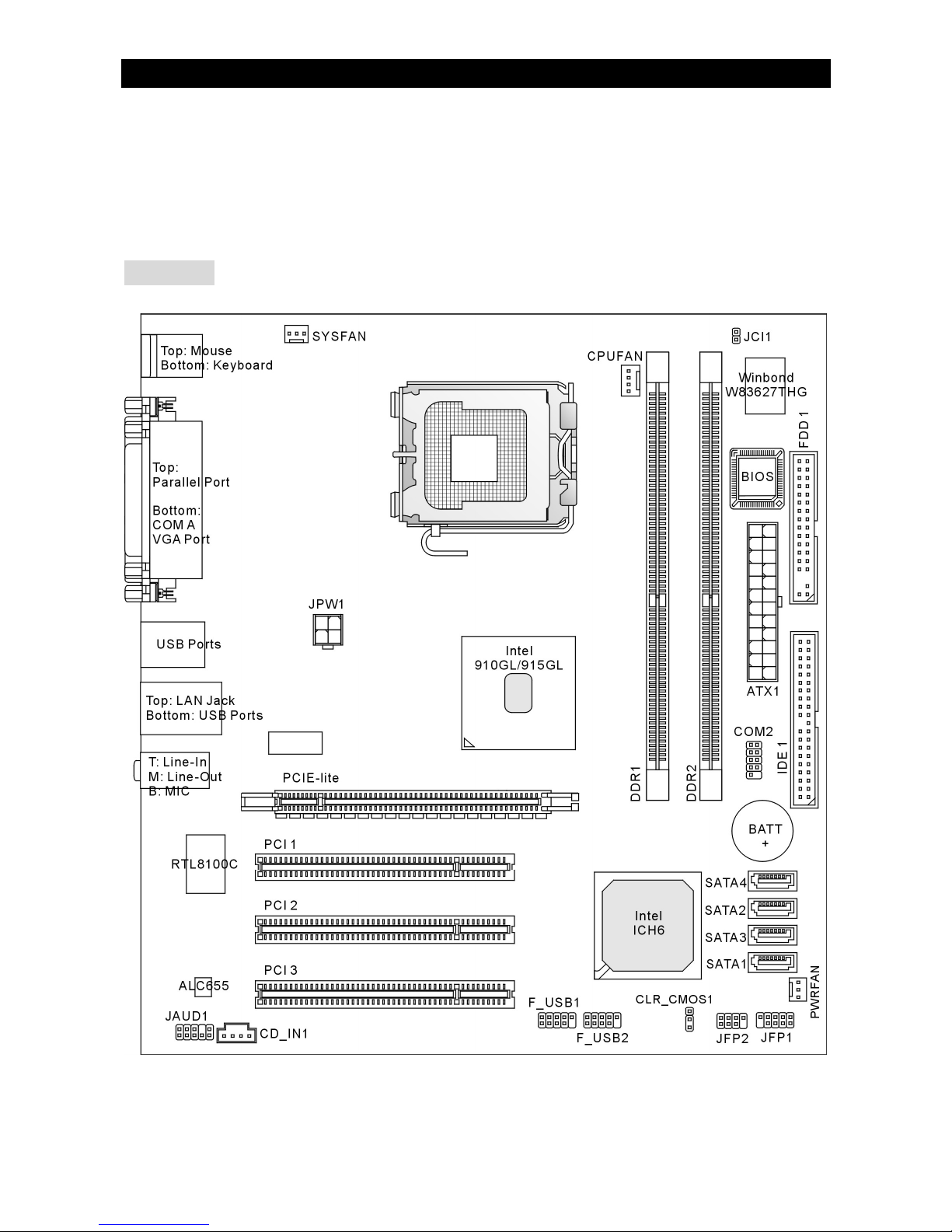
Thank you for choosing the 910GLM2-V/915GLM2-V (MS-7269 v1.X) Micro-ATX mainboard.
The 910GLM2-V/915GLM2-V is based on Intel® 910GL/915GL & Intel® ICH6 chipsets for
optimal system efficiency. Designed to fit the advanced Intel® P4 Celeron-D/Prescott
533/800MHz processors in LGA775 package, the 910GLM2-V/915GLM2-V delivers a high
performance and professional desktop platform solution.
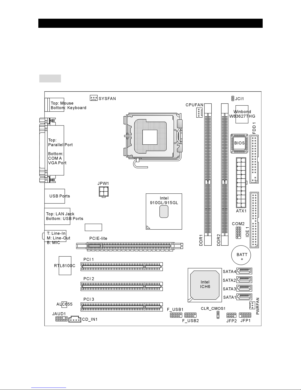
Layout
Page 8

2
Specifications
CPU
l Supports Intel® Pentium 4 Celeron-D/Prescott processor in LGA775 package
l Supports 533/800MHz FSB
l Supports Intel Hyper-Threading Technology
(For the latest information about CPU, please visit
http://www.msi.com.tw/program/products/mainboard/mbd/pro_mbd_cpu_support.php)
Chipset
l Intel® 910GL/915GL chipset
- Supports FSB 533/800MHz
- Supports DDR 400/333 memory interface
- Integrated graphics controller
l Intel® ICH6 chipset
- Hi-Speed USB (USB2.0) controller, 480Mb/s, 8 ports
- 4 Serial ATA ports with transfer rate up to 150MB/s
- 1 channel Ultra ATA 66/100 bus Master IDE controller
- PCI Master v2.3, I/O APIC
- Supports both ACPI and legacy APM power management
Main Memory
l Supports two DIMMs of dual-channel, 2.5Volt DDR 400/333 SDRAM
l Supports maximum memory size of 2GB
(For the updated supporting memory modules, please visit
http://www.msi.com.tw/program/products/mainboard/mbd/pro_mbd_trp_list.php)
Slots
l One PCI Express Lite slot for PCI Express x16 graphics card. For the information of
compatible PCI Express VGA cards, please refer to the “Supported PCI Express VGA Card
List for PCI Express Lite Slot (PCI Express x4).”
l Three PCI 2.3 32-bit PCI bus slots (support 3.3v/5v PCI bus interface)
HDD Interface
l One Ultra DMA 66/100 IDE controller integrated in ICH6
- Supports PIO, Bus Master operation modes
- Can connect up to two Ultra ATA drives
l Serial ATA/150 controller integrated in ICH6
- Up to 150MB/s transfer speeds
- Can connect up to four Serial ATA drives
Onboard Peripherals
l Onboard Peripherals include:
Page 9

3
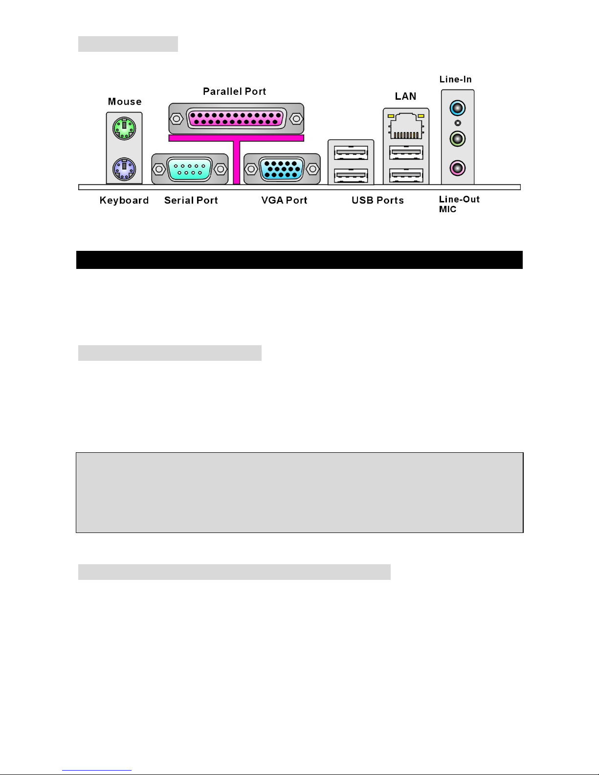
- 1 floppy port supports 1 FDD with 360K, 720K, 1.2M, 1.44M and 2.88Mbytes
- 2 serial ports (Rear * 1/ Front * 1)
- 1 parallel port supports SPP/EPP/ECP mode
- 8 USB 2.0 ports (Rear * 4/ Front * 4)
- 1 Line-In/Line-Out/Mic-In audio port
- 1 RJ-45 LAN Jack
- 1 VGA port
Audio
l AC97 link controller integrated in Intel ICH6 chipset
l Realtek ALC655 6-channel audio codec
- Compliance with AC97 v2.3 Spec.
- Meets PC99/2001 audio performance requirement
LAN
l Realtek RTL8100C
- Supports 10/100 Mbps
- Supports ACPI Power Management
BIOS
l The mainboard BIOS provides “Plug & Play” BIOS which detects the peripheral devices and
expansion cards of the board automatically
l The mainboard provides a Desktop Management Interface (DMI) function that records your
mainboard specifications
l 4Mb FWH
Dimension
l Micro ATX Form Factor: 24.4cm x 24.4cm
Mounting
l 6 mounting holes
Page 10
4
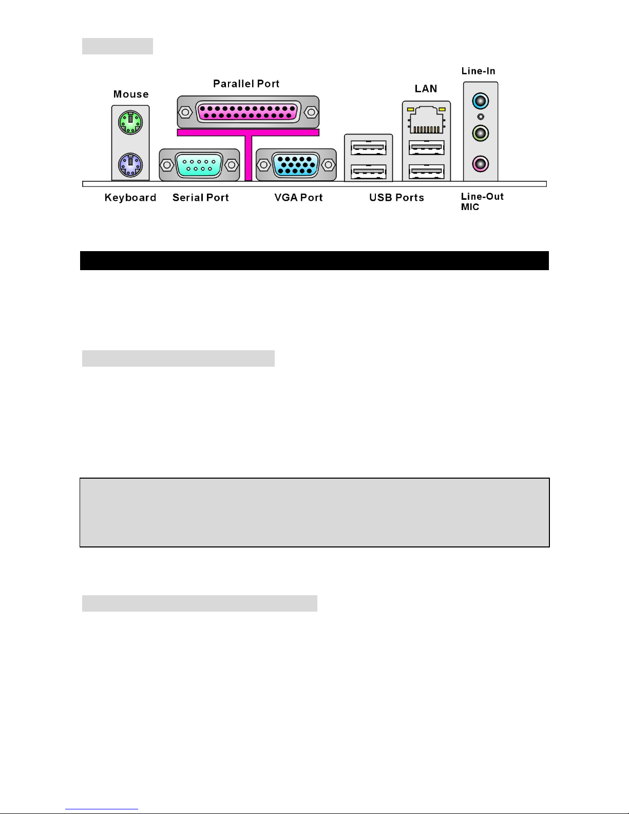
Rear Panel
The rear panel provides the following connectors:
Hardware Setup
This chapter tells you how to install the CPU, memory modules, and expansion cards, as well as
how to setup the jumpers on the mainboard. It also provides the instructions on connecting the
peripheral devices, such as the mouse, keyboard, etc. While doing the installation, be careful in
holding the components and follow the installation procedures.
Central Processing Unit: CPU
The mainboard supports Intel® Pentium 4 Celeron-D/Prescott processor and uses LGA775 CPU
socket. When you are installing the CPU, make sure that you install the cooler to prevent the
CPU from overheating. If you do not have the CPU cooler, contact your dealer to purchase and
install them before turning on the computer.
For the latest information about CPU, please visit
http://www.msi.com.tw/program/products/mainboard/mbd/pro_mbd_cpu_support.php.
MSI Reminds You...
Overheating
Overheating will seriously damage the CPU and system; always make sure the cooling fan can
work properly to protect the CPU from overheating.
LGA775 CPU and Cooler Installation
When you are installing the CPU, make sure the CPU has a cooler attached on the top to prevent
overheating. If you do not have the cooler, contact your dealer to purchase and install them
before turning on the computer. Meanwhile, do not forget to apply some silicon heat transfer
compound on CPU before installing the cooler for better heat dispersion.
Follow the steps below to install the CPU & cooler correctly. Wrong installation will cause the
damage of your CPU & mainboard.
Page 11

5
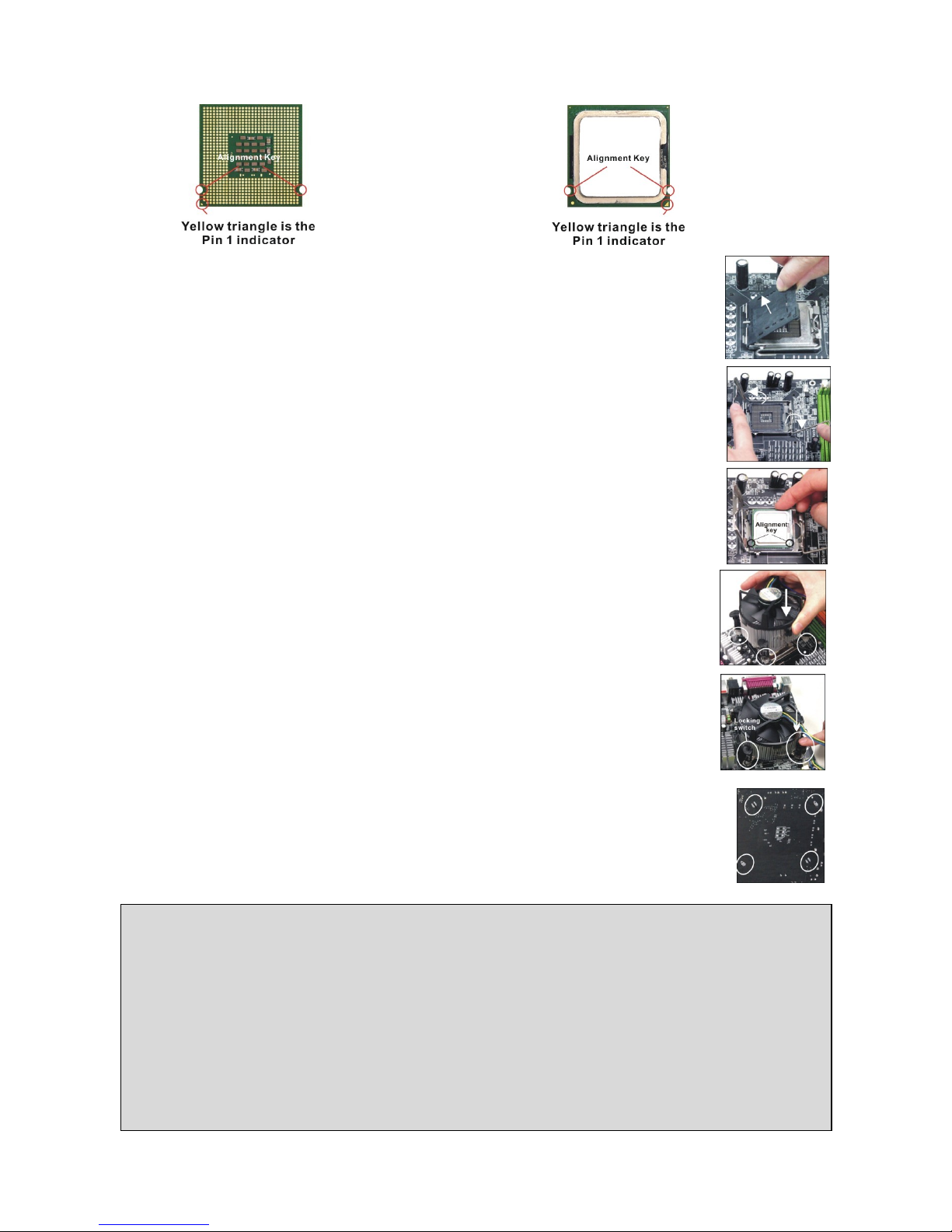
Introduction to LGA 775 CPU
The pin-pad side of LGA 775 CPU The surface of LGA 775 CPU
Remember to apply some silicone heat transfer compound on it for better heat dispersion.
1. The CPU socket has a plastic cap on it to protect the contact from damage.
Before you install the CPU, always cover it to protect the socket pin.
2. Remove the cap from lever hinge side.
3. The pins of socket reveal.
4. Open the load lever.
5. Lift the load lever up and open the load plate.
6. After confirming the CPU direction for correct mating, put down the CPU in
the socket housing frame. Be sure to grasp on the edge of the CPU base. Note that the
alignment keys are matched.
7. Visually inspect if the CPU is seated well into the socket. If not, take out the
CPU with pure vertical motion and reinstall.
8. Cover the load plate onto the package.
9. Press down the load lever lightly onto the load plate, and then secure the
lever with the hook under retention tab.
10. Align the holes on the mainboard with the cooler. Push down the cooler until
its four clips get wedged into the holes of the mainboard.
11. Press the four hooks down to fasten the cooler. Then rotate
the locking switch (refer to the correct direction marked on it)
to lock the hooks.
12. Turn over the mainboard to confirm that the clip-ends are
correctly inserted.
Reminds You...
1. Confirm if your CPU cooler is firmly installed before turning on your system.
2. Check the information in PC Health Status of H/W Monitor in BIOS for the CPU temperature.
3. Do not touch the CPU socket pins to avoid damage.
4. Whenever CPU is not installed, always protect your CPU socket pin with the plastic cap
covered to avoid damage.
5. Due to the limitation of the mating/unmating CPU durability, we suggest that you do not
plug/unplug the CPU too often.
Page 12
6
Memory
The mainboard provides two unbuffered DDR 333/400 DIMMs. It supports the memory size up to
2GB. To operate properly, at least one DIMM module must be installed.
(For the updated supporting memory modules, please visit
http://www.msi.com.tw/program/products/mainboard/mbd/pro_mbd_trp_list.php)
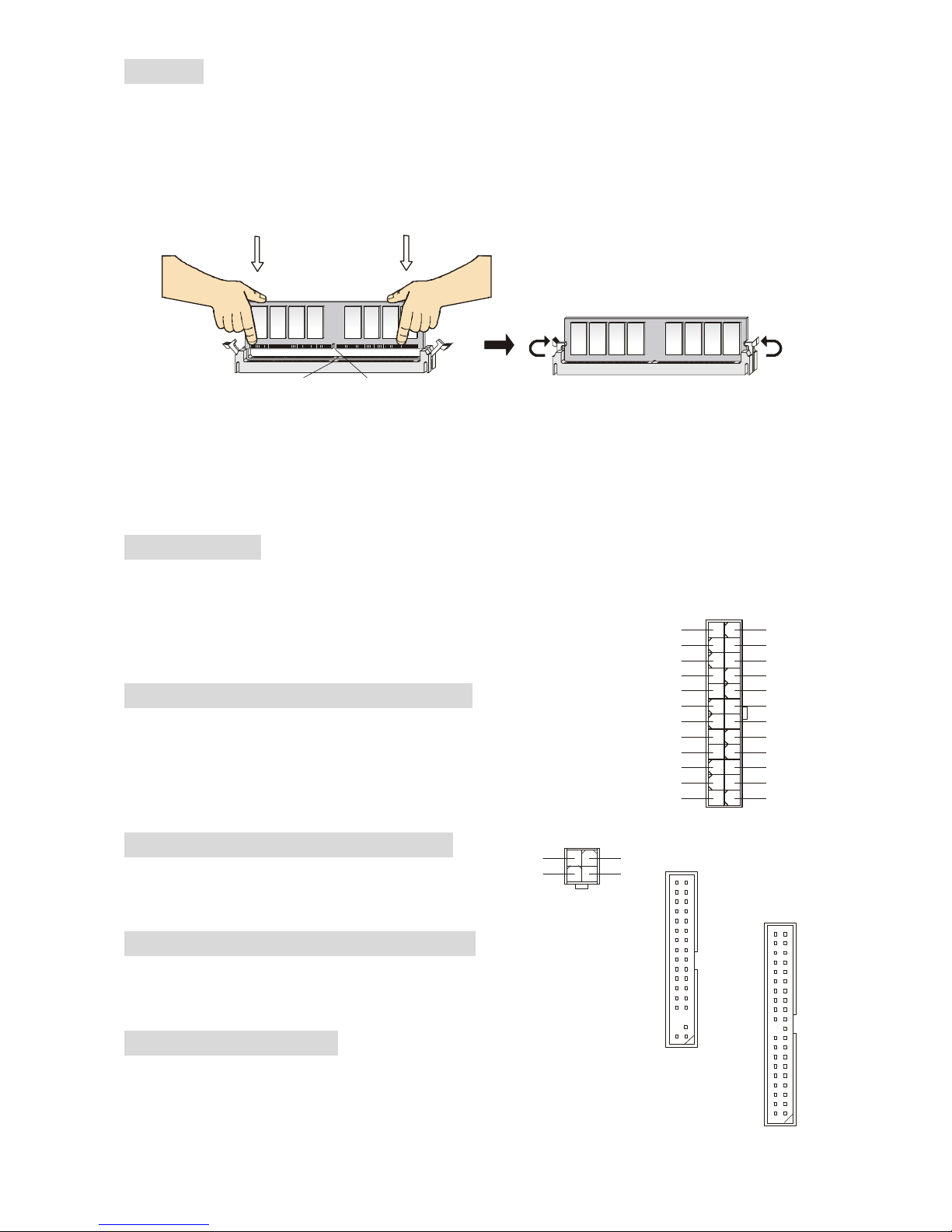
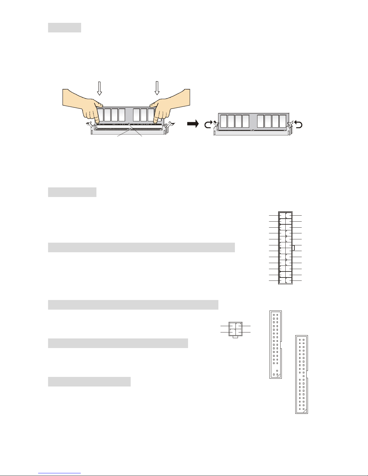
Installing DDR Modules
1. The DIMM has only one notch on the center of module. The module will only fit in the right
orientation.
2. Insert the DIMM memory module vertically into the DIMM slot. Then push it in until the
golden finger on the memory module is deeply inserted in the socket.
3. The plastic clip at each side of the DIMM slot will automatically close.
Power Supply
The mainboard supports ATX power supply for the power system. Before inserting the power
supply connector, always make sure that all components are
installed properly to ensure that no damage will be caused. A 300W
or above power supply is suggested.
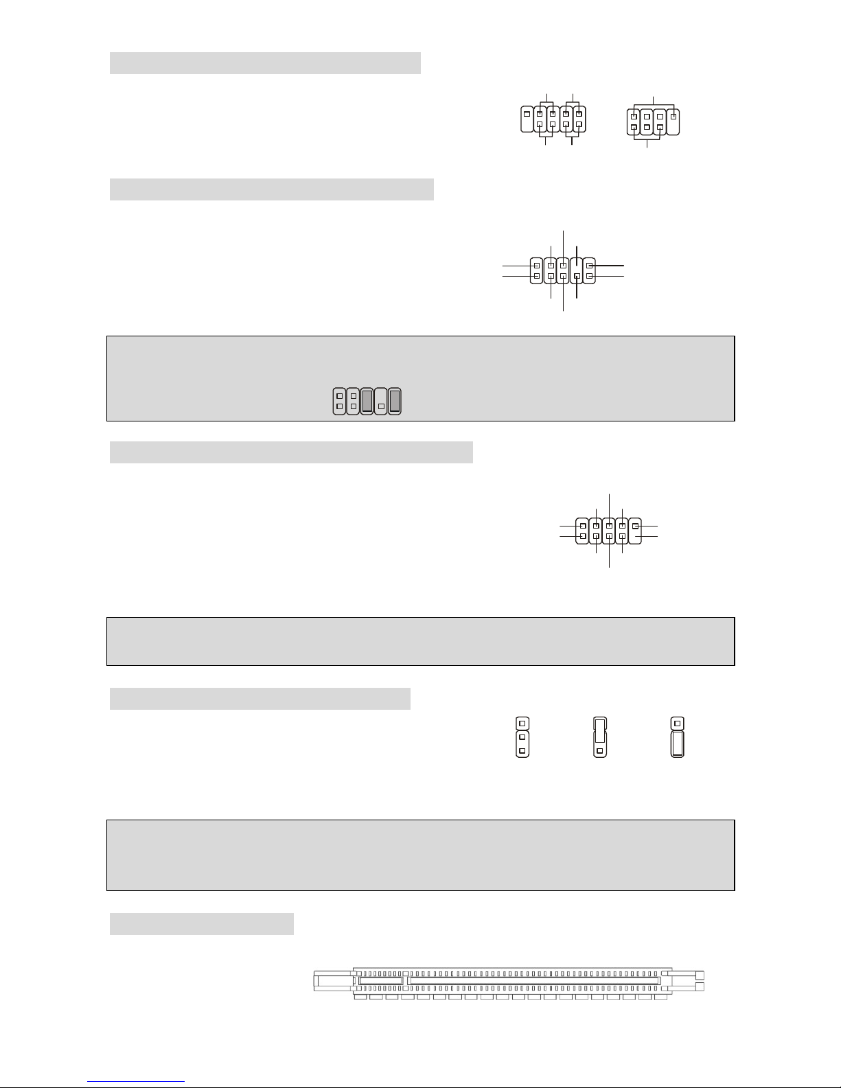
ATX 24-Pin Power Connector: ATX1
This connector allows you to connect an ATX 24-pin power supply.
To connect the ATX 24-pin power supply, make sure the plug of the
power supply is inserted in the proper orientation and the pins are
aligned. Then push down the power supply firmly into the connector.
ATX 12V Power Connector: JPW1
This 12V power connector is used to provide power
to the CPU.
Floppy Disk Drive Connector: FDD1
The mainboard provides a standard floppy disk drive connector that
supports 360K, 720K, 1.2M, 1.44M and 2.88M floppy disk types.
IDE Connectors: IDE1
The mainboard has a 32-bit Enhanced PCI IDE and Ultra DMA 66/100 controller that
provides PIO mode 0~4, Bus Master, and Ultra DMA 66/100 function. You can
connect up to two hard disk drives, CD-ROM, 120MB Floppy and other devices.
Notch
Volt
1
12
24
13
+3.3V
+3.3V
-12V+3.3V
GNDGND
PS-ON#
+5V
GNDGND
GND+5V
GNDGND
ResPWR OK
+5V5VSB
+5V+12V
+5V+12V
GNDNC
1
3
4
2
GND
12V
GND
12V
Page 13
7
The first hard drive should always be connected to IDE1. IDE1 can connect a Master and a Slave
drive. You must configure second hard drive to Slave mode by setting the jumper accordingly.
MSI Reminds You...
If you install two hard disks on cable, you must configure the second drive to Slave mode by
setting its jumper. Refer to the hard disk documentation supplied by hard disk vendors for jumper
setting instructions.
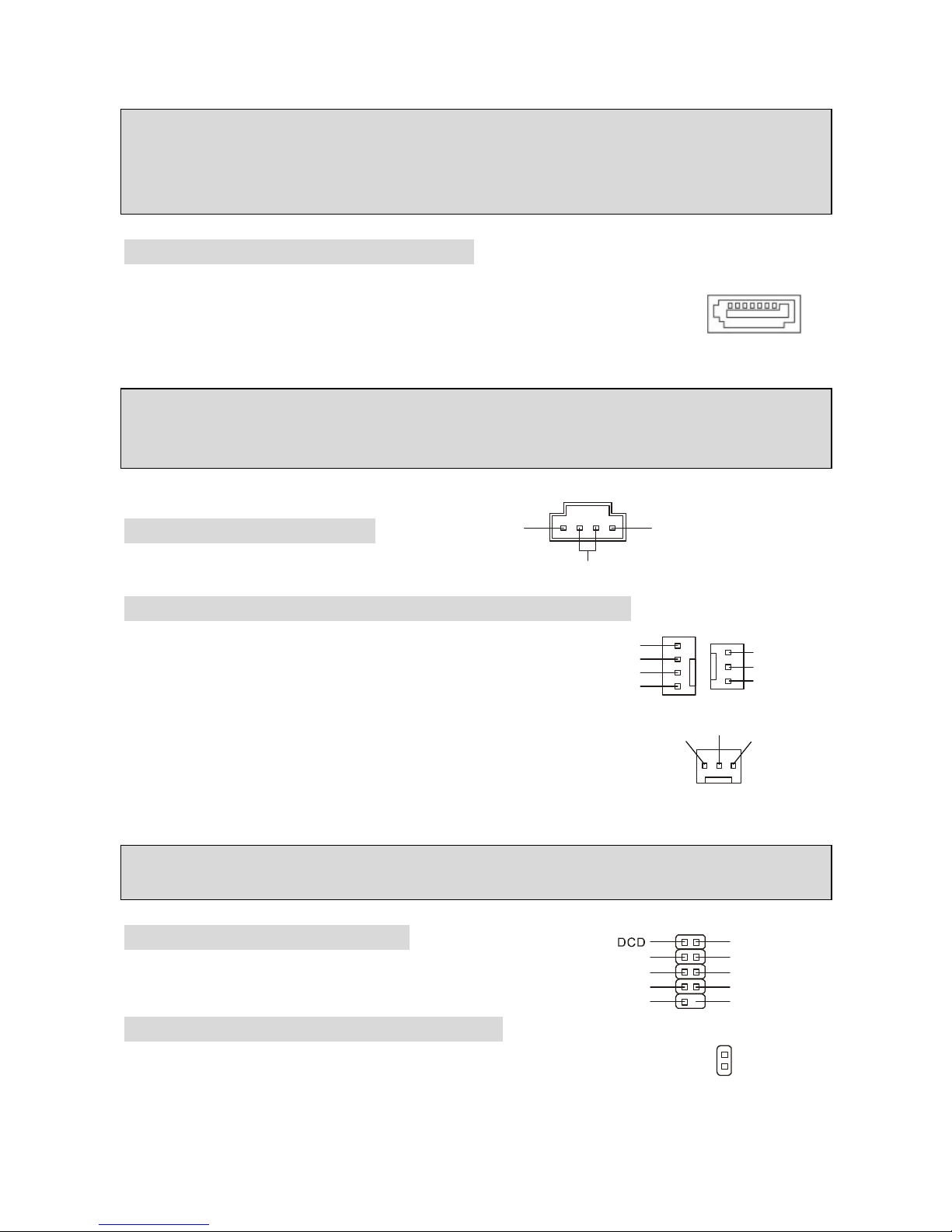
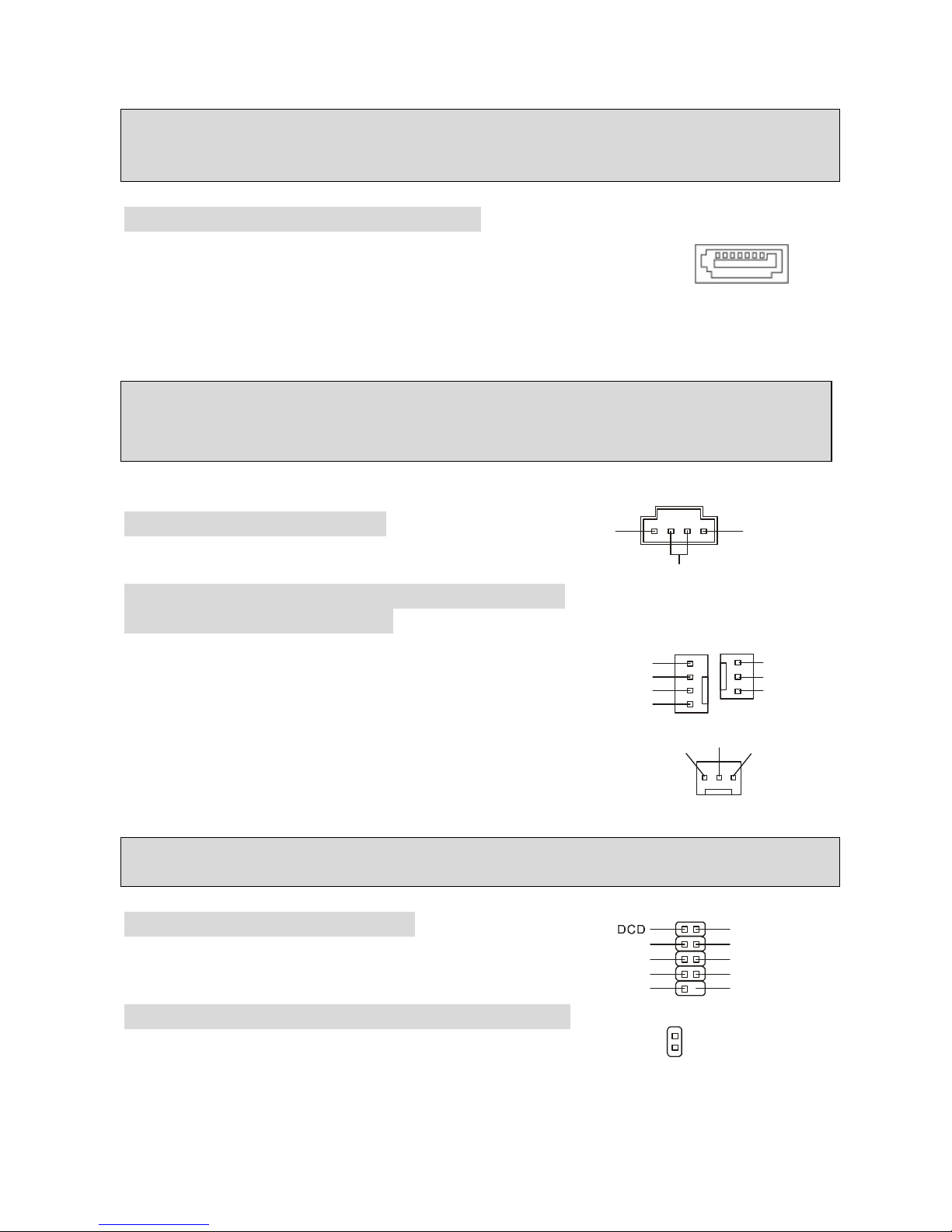
Serial ATA Connectors: SATA1/2/3/4
The Intel ICH6 Southbridge supports four serial connectors SATA1~4.
SATA1~4 are high-speed Serial ATA interface ports. Each supports 1st
generation serial ATA data rates of 150 MB/s. All SATA connectors are fully
compliant with Serial ATA 1.0 specifications. Each Serial ATA connector can connect to 1 hard
disk device.
MSI Reminds You...
Please do not fold the serial ATA cable into 90-degree angle. Otherwise, data loss may occur
during transmission.
CD-In Connector: CD_IN1
The connector is for CD-ROM audio connector.
Fan Power Connectors: CPUFAN/SYSFAN/PWRFAN
The fan power connectors support system cooling fans with
+12V. CPUFAN can support three- or four-pin head
connector. When connecting the wire to the connectors,
always take note that the red wire is the positive and should be
connected to the +12V, the black wire is Ground and should be
connected to GND. If the mainboard has a System Hardware Monitor
chipset onboard, you must use a specially designed fan with speed
sensor to take advantage of the CPU fan control.
MSI Reminds You...
Always consult the vendors for proper CPU cooling fan.
Serial Port Connector: COM2
The mainboard provides one serial port header for you to
connect secondary serial devices.
Chassis Intrusion Switch Header: JCI1
This connector is connected to a 2-pin chassis switch. If the chassis is
opened, the switch will be short. The system will record this status and show
a warning message on the screen. To clear the warning, you must enter the BIOS utility and clear
the record.
L
R
GND
GND
DSR
RTS
CTSRIKEY
SOUT
SIN
DTR
9110
2
GND
CINTRU
1
2
GND
+12V
Sensor
GND
+12V
Sensor
Control
GND
+12V
Sensor
Page 14
8
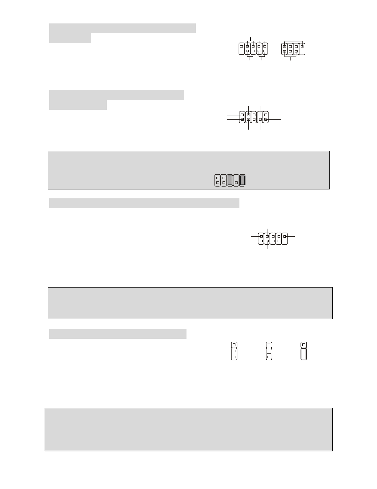
Front Panel Connectors: JFP1/JFP2
The mainboard provides two front panel connectors for
electrical connection to the front panel switches and LEDs.
The JFP1 is compliant with Intel Front Panel I/O
Connectivity Design Guide.
Front Panel Audio Connector: JAUD1
The front panel audio connector allows you to
connect to the front panel audio and is
compliant with Intel® Front Panel I/O
Connectivity Design Guide.
MSI Reminds You...
If you do not want to connect to the front audio header, pins 5 & 6, 9 & 10 have to be jumpered in
order to have signal output directed to the rear audio ports. Otherwise, the Line-Out connector on
the back panel will not function.
1
9210
Front USB Connectors: F_USB1 / F_USB2
The mainboard provides two standard USB 2.0 pinheaders.
USB2.0 technology increases data transfer rate up to a
maximum throughput of 480Mbps, which is 40 times faster
than USB 1.1, and is ideal for connecting high-speed USB
interface peripherals such as USB HDD, digital cameras,
MP3 players, printers, modems and the like.
MSI Reminds You...
Note that the pins of VCC and GND must be connected correctly to avoid possible damage.
Clear CMOS Jumper: CLR_CMOS1
There is a CMOS RAM on board that has a power supply
from external battery to keep the data of system
configuration. With the CMOS RAM, the system can
automatically boot OS every time it is turned on. If you
want to clear the system configuration, use this jumper to clear data.
MSI Reminds You...
You can clear CMOS by shorting 2-3 pin while the system is off. Then return to 1-2 pin position.
Avoid clearing the CMOS while the system is on; it will damage the mainboard.
PCI Express Lite Slot
The PCI Express Lite slot (PCI Express x4) is a special design that supports only the following
compatible PCI-E x16 VGA
cards and runs at x4 speed.
1
1
133
322
2
Keep Data
Clear Data
(2)VCC
USB1- GND
GND
USB0-
USB0+
USB1+
USB0C(10)
(1)VCC Key(9)
(2)AUD_GND
AUD_VCC
AUD_RET_R
Key
AUD_RET_L(10)
(1)AUD_MIC
AUD_MIC_BIAS
AUD_FPOUT_R
HP_ON
AUD_FPOUT_L(9)
JFP2
Power
LED
Speaker
1
728
JFP1
Power
LED
HDD
LED
Reset
Switch
Power
Switch
192
10
Page 15

9
Supported PCI Express VGA Card List for PCI Express Lite Slot (PCI Express x4)
VGA Chip VGA Memory Type
VGA BIOS Result
Radeon X300SE ASUS EAX300SE/TD/128M/A 128MB, DDR SDRAN 008.015.117.000 OK
Radeon X600 ELSA FALCOX X60 XT 128MB/DDR SGRAM 008.015.115.000 OK
Radeon X600 Pro ELSA FALCOX X60 Pro 128MB/DDR SDRAM 008.015.120.000 OK
Radeon X600XT MSI MS-8961 128MB/DDR SGRAM 008.015.117.000 OK
Radeon X600XT Power Color R38A-TC3 X600 XT 128MB/DDR SDRAM 008.015.095.000 OK
Radeon X700 Pro MSI MS-8978 256MB/DDR3 SGRAM 009.004.001.032 OK
Radeon X800 Pro MSI MS-8997 Ver: 1 128MB, DDR SDRAN 113-A3210-100 OK
Radeon X850 ELSA FALCOX X85 XTP 256MB/GDDR3 SDRAM 113-A47401-102 OK
ATI
Radeon X850XT ATI X850XT 256MB/DDR SGRAM 009.007.001.004 OK
GeForce 6200 MSI MS-8981 Ver:100 128MB, DDR SDRAN 5.43.02.16.11 OK
GeForce 6200 Turbo Cache Gigabyte GV-NX62TC256D 256MB/DDR SDRAM 5.44.02.11.00 OK
GeForce 6600GT MSI MS-8979 Ver:11B 128MB, DDR SDRAN 5.43.02.64.00 OK
GeForce 6600GT MSI MS-8983 Ver: 200 128MB, DDR SDRAN 5.43.02.16.00 OK
GeForce 6800 MSI MS-8984 Ver:20B 128MB, DDR SDRAN 5.41.02.37.00 OK
GeForce 6800GT MSI MS-8974 256MB/DDR SDRAM 5.40.02.30.03 OK
GeForce 6800GT Nvidia GeForce 6800 Series GPL 256MB/DDR3 SGRAM 5.40.02.15.03 OK
GeForce FX5200 MSI MS-8968 128MB, DDR SDRAN 4.34.20.76.13 OK
GeForce FX5700 MSI MS-8969 128MB, DDR SDRAN 4.36.20.38.12 OK
GeForce NX6600 MSI MS-8981 256MB/DDR SDRAM 5.43.02.27 OK
GeForce NX7800GTX MSI 256MB/DDR3 SGRAM 5.70.02.11.10 OK
GeForce PCX5750 ASUS EN5750 128MB/DDR SDRAM 4.36.20.38.00 OK
GeForce PCX5750 Leadtek Winfast PX360 TD 128MB/DDR SDRAM 4.36.20.38.00 OK
GeForce PCX5750 MSI MS-8969 128MB/DDR SDRAM 4.36.20.38.12 OK
Nvidia
GeForce PCX5900 ELSA Gladiac PCX935 128MB/DDR SGRAM 4.35.20.45.E0 OK
NOTE: The 910GL/915GL Northbridges integrate graphics controllers. Hence, if you intend to
use your own PCI Express VGA card, please follow the instructions:
1. Install your onboard VGA driver.
2. Restart the PC and install your VGA card driver.
3. Restart the PC and enter the OS.
4. Go to Control Panel and double click the Display icon.
5. Set your VGA card as the primary display interface (displayed as 1 is primary).
6. Restart your PC.
7. Dual-Display mode is activated.
Page 16

10
PCI (Peripheral Component Interconnect) Slots
The PCI slots allow you to insert the expansion cards to meet your needs. When adding or
removing expansion cards, make sure that you
unplug the power supply first. Meanwhile, read
the documentation for the expansion card to make any necessary hardware or software settings
for the expansion card, such as jumpers, switches or BIOS configuration.
PCI Interrupt Request Routing
The IRQ, abbreviation of interrupt request line and pronounced I-R-Q, are hardware lines over
which devices can send interrupt signals to the microprocessor. The PCI IRQ pins are typically
connected to the PCI bus INT A# ~ INT D# pins as follows:
Order1 Order2 Order3 Order4
PCI Slot 1 INT A# INT B# INT C# INT D#
PCI Slot 2 INT B# INT C# INT D# INT A#
PCI Slot 3 INT C INT D# INT A# INT B#
BIOS Setup
Power on the computer and the system will start POST (Power On Self Test) process. When the
message below appears on the screen, press <DEL> key to enter Setup.
Press DEL to enter Setup
If the message disappears before you respond and you still wish to enter Setup, restart the
system by turning it OFF and On or pressing the RESET button. You may also restart the system
by simultaneously pressing <Ctrl>, <Alt>, and <Delete> keys.
Main Page
Standard CMOS Features
Use this menu for basic system configurations, such as time, date etc.
Page 17
11
Advanced BIOS Features
Use this menu to setup the items of Award special enhanced features.
Advanced Chipset Features
Use this menu to change the values in the chipset registers and optimize your system
performance.
Integrated Peripherals
Use this menu to specify your settings for integrated peripherals.
Power Management Setup
Use this menu to specify your settings for power management.
PNP/PCI Configurations
This entry appears if your system supports PnP/PCI.
PC Health Status
This entry shows your hardware & PC health status.
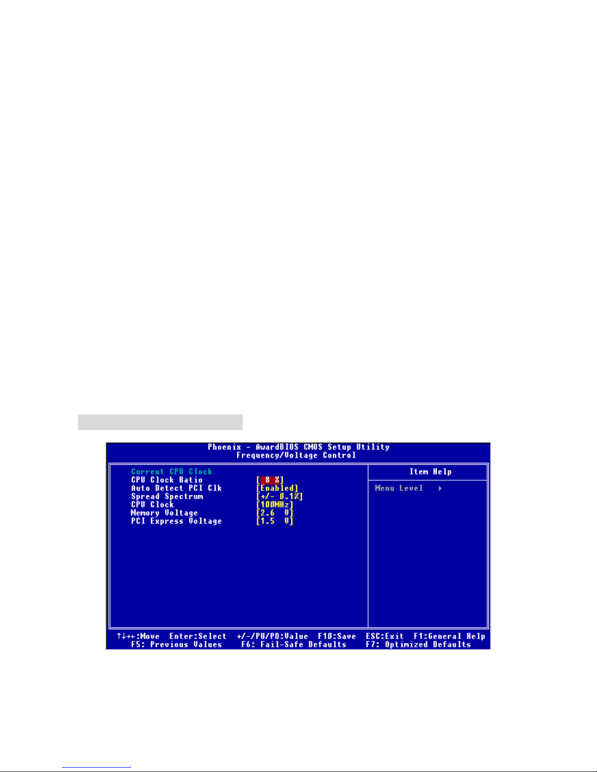
Frequency/Voltage Control
Use this menu to configure the settings of frequency/voltage.
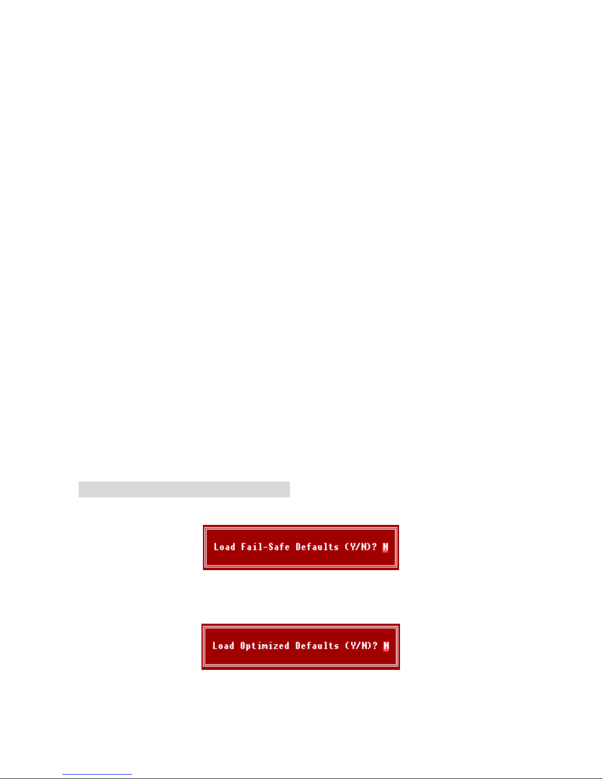
Load Fail-Safe/Optimized Defaults
The two options on the main menu allow users to restore all of the BIOS settings to the default
Fail-Safe or Optimized values.
Set Supervisor/User Password
The Supervisor Password allows users to enter and change the settings of the BIOS setup utility.
Users with the User Password are only allowed to enter but do not have the right to change the
settings of the BIOS setup menu.
Save & Exit Setup
Save changes to CMOS and exit setup.
Exit Without Saving
Abandon all changes and exit setup.
Frequency/Voltage Control
Current CPU Clock
It shows the current clock of the CPU. Read-only.
Page 18
12
CPU Clock Ratio
This setting controls the multiplier that is used to determine the internal clock speed of the
processor relative to the external or motherboard clock speed. It is available only when the
processor supports this function.
Auto Detect PCI Clk
This item is used to auto detect the PCI slots. When set to [Enabled], the system will remove
(turn off) clocks from empty PCI slots to minimize the electromagnetic interference (EMI).
Settings: [Enabled], [Disabled].
Spread Spectrum
When the motherboard’s clock generator pulses, the extreme values (spikes) of the pulses
create EMI (Electromagnetic Interference). The Spread Spectrum function reduces the EMI
generated by modulating the pulses so that the spikes of the pulses are reduced to flatter curves.
If you do not have any EMI problem, leave the setting at [Disabled] for optimal system stability
and performance. But if you are plagued by EMI, select the desired range for EMI reduction.
Remember to disable Spread Spectrum function if you are overclocking, because even a slight
jitter can introduce a temporary boost in clock speed which may just cause your overclocked
processor to lock up.
CPU Clock
This item allows you to select the CPU Front Side Bus clock frequency (in MHz) and overclock
the processor by adjusting the FSB clock to a higher frequency.
Memory Voltage
Adjusting the DDR voltage can increase the DDR speed. Any changes made to this setting may
cause a stability issue, so changing the DDR voltage for long-term purpose is NOT
recommended.
PCI Express Voltage
The PCI Express voltage is adjustable in the field, allowing you to increase the performance of
your graphics card when overclocking. Note that any changes made to this setting may cause a
stability issue.
Load Fail-Safe/Optimized Defaults
The Fail-Safe Defaults are the default values set by the BIOS vendor for stable system
performance.
The Optimized Defaults are the default values set by the mainboard manufacturer specifically for
optimal performance of the mainboard.
Page 19
13
Introduction
Félicitations, vous venez d’acquérir une carte mère des séries Micro-ATX
910GLM2-V/915GLM2-V (MS-7269 v1.0). Les Séries 910GLM2-V/915GLM2-V sont basées sur
les chipsets Intel® 910GL/915GL & Intel® ICH6, offrant un système très performant. La carte
fonctionne avec les processeurs Intel® P4 Celeron-D/Prescott 533/800MHz et comporte LGA775
de package. Les transmissions 910GLM2-V/915GLM2-V sont très performantes et offrent une
solution adaptée tant aux professionnels qu’aux particuliers.
Schéma
Page 20

14
Spécificités
CPU
l Supporte les processeurs Intel® Pentium 4 Celeron-D/Prescott sur socket LGA775
l Supporte FSB533MHz, 800MHz
l Supporte la technologie Intel Hyper-Threading
(Pour plus d’information, veuillez visiter
http://www.msi.com.tw/program/products/mainboard/mbd/pro_mbd_cpu_support.php)
Chipset
l Chipset Intel® 910GL/915GL
- Supporte FSB 533/800 MHz
- Supporte l’interface de mémoire DDR 400/333
- Contrôleur graphique Intégré
l Chipset Intel® ICH6
- Contrôleur USB (USB2.0) Hight-Speed, 480Mb/s, jusqu’à 8 ports
- 4 ports Série ATA avec un taux de transfert jusqu'à 150MB/s
- 1 contrôleur canal Ultra ATA 66/100 bus Master IDE
- PCI Master v2.3, I/O API
- Supporte l’ACPI et l’APM Power Management
Mémoire Principale
l Supporte deux DIMMs de canal double de 2.5Volt DDR 400/333 SDRAM
l Supporte une taille de mémoire jusqu' à 2GB
(Pour plus d’information, veuillez visiter
http://www.msi.com.tw/program/products/mainboard/mbd/pro_mbd_trp_list.php)
Slots
l Un Lite slot PCI Express pour la carte graphique PCI Express x16 (Pour plus d’information
sur la carte de VGA PCI Express, référez-vous au “Supported PCI Express VGA Card List for
PCI Express Lite Slot (PCI Express x4)”
l Trois PCI 2.3 32-bit PCI bus slots (supporte l’ interface 3.3v/5v PCI bus)
Interface du HDD
l Un contrôleur Ultra DMA 66/100 IDE intégré dans ICH6
- Supporte PIO, Bus Master modes d’opération
- Peut connecter jusqu’à deux périphériques Ultra ATA
l Contrôleur Série ATA/150 intégré dans ICH6
- Vitesse de transfert jusqu’à 150MB/s
- Peut connecter jusqu’à quatre périphériques Série ATA
Périphériques intégrés
l Périphériques intégrés inclus:
- 1 port floppy incluant 1 FDD avec 360K, 720K, 1.2M, 1.44M et 2.88Mbytes
Page 21

15
- 2 ports séries (1 Arrière*1 / Façade*1)
- 1 port parallèle supportant le mode SPP/EPP/ECP
- 8 ports USB2.0 (Arrière*4/ Façade*4)
- 1 Line-in/Line-out/Mic-In port audio
- 1 RJ-45 LAN Jack
- 1 port VGA
Audio
l Contrôleur link AC97 intégré dans le chipset Intel ICH6
l Realtek ALC655 6-canal audio codec
- Compatible avec les Spec. AC97 v2.3
- Compatible avec les performances audio PC99/2001
LAN
l Realtek RTL8100C
- Supporte 10/100 Mb/s
- Supporte l’ACPI Power Management
BIOS
l La carte mère utilise un BIOS “Plug & Play ” détectant les périphériques ainsi que les cartes
d’extension de façon automatique.
l La carte comporte une fonction DMI (Desktop Management Interface) qui enregistre les
spécifications de la carte mère.
l 4Mb FWH
Dimension
l Format Micro-ATX: 24.4cm x 24.4cm
Montage
l 6 trous de montage.
Page 22
16
Panneau Arrière
Le panneau arrière procure les connecteurs suivants:
Installation Matériel
Ce chapitre vous indique comment installer le CPU, les modules de mémoire, les cartes
d’extension et les jumpers, explique également comment se connecter à des dispositifs
périphériques tels que la souris, le clavier etc. Lors de l’installation du matériel, veuillez suivre
les instructions de montage pour éviter d’endommager quoi que ce soit.
Central Processing Unit: CPU
La carte supporte les processeurs Intel® Pentium 4 Celeron-D/Prescott. Elle utilise le Socket
LGA775 pour une installation plus simple. Assurez-vous que vous possédez bien un ventilateur
et un dissipateur pour éviter la surchauffe. Si vous ne savez pas quel ventilateur utilisé, veuillez
contacter votre revendeur avant de mettre en marche votre PC
Pour plus d’information, veuillez visiter
http://www.msi.com.tw/program/products/mainboard/mbd/pro_mbd_cpu_support.php.
MSI Vous Rappelle...
Surchauffe
Une surchauffe peut sérieusement endommager le CPU et le système, assurez-vous toujours
que le système de refroidissement fonctionne correctement pour protéger le CPU d’une
surchauffe.
Installation du LGA775 CPU et du Refroidissement
Quand vous installerez votre CPU, assurez vous que le CPU possède un système de
refroidissement pour prévenir les surchauffes. Si vous ne possédez pas de système de
refroidissement, contactez votre revendeur pour vous en procurer un et installez le avant
d’allumer l’ordinateur. N’oubliez pas d’utiliser des composants en silicium de transfert de chaleur
avant d’installer le refroidissement pour une meilleure dissipation de la chaleur.
Suivez les mesures suivantes pour installer correctement le système refroidissement & le CPU,
sinon, une mauvaise installation risque d’endommager votre CPU et la carte mère.
Page 23
17
Introduction du LGA 775 CPU
La face de la galette à contacts du LGA 775 CPU La surface duLGA 775 CPU
N’oubliez pas d'appliquer un composé en silicone de transfert thermique pour
une meilleure dispersion de chaleur.
1. Le socket CPU possède un plastique de protection. Ne le retirer qu’au
moment d’installer le CPU.
2. Enlevez le chapeau de la charnière du levier.
3. On révéle les broches de la douille
4. Ouvrez le levier de charge.
5. Lever le levier et ouvrir le plateau de chargement.
6. Après avoir confirmé la direction du CPU pour joindre correctement, déposez
le CPU dans l'armature du logement de douille. Faites attention au bord de
sa base. Notez qu’on aligne les coins assortis .
7. Inspectez visuellement si le CPU est posé bien dans la douille. Si non,
sortez verticalement le CPU pur et la réinstallez.
8. Couvrez le plat de charge sur le paquet.
9. Abaisser le levier sur le plateau de chargement, puis sécuriser l’ensemble
avec le mécanisme de rétention.
10. Aligner les trous de la carte avec ventilateur. Installer le ventilateur
dans les trous de la carte mère.
11. Appuyer sur le crochets pour attacher le ventilateur. Puis effectuer une
rotation des systèmes de rétention (voir ventilateur pour le sens de rotation).
12. Retourner la carte mère pour s’assurer que le ventilateur est correctement
installé
MSI Vous Rappelle...
1. Vérifier la connexion du ventilateur de CPU avant de démarrer le PC.
2. Vérifier les informations dans le BIOS PC Health Status (voir chapitre 3 pour les détails)
au sujet de la température du CPU.
3. Ne pas toucher les broches du CPU pour éviter de les endommager.
4. Si vous êtes amené à retirer votre CPU, ne pas oublier de remettre la protection (capot)
en plastique sur le socket (voir figure 1).
5. A noter que la mise en place du CPU est prévue pour une vingtaine de connexion,
cependant il n’est pas recommandé d’installer/retirer le CPU trop souvent.
Page 24
18
Mémoire
La carte mère possède deux unbuffered DIMMs DDR 333/400. et supporte au maximum 2GB de
mémoire. Pour fonctionner correctement, il faut au moins installer un module de mémoire DIMM
sur les slots. ( Pour plus d’information, veuillez visiter
http://www.msi.com.tw/program/products/mainboard/mbd/pro_mbd_trp_list.php)
Installez les Modules DDR
1. Le DIMM ne possède qu’une encoche en son centre. Ainsi il n’est possible de monter le
module que dans un seul sens
2. Insérez verticalement le module de mémoire DIMM dans le slot. Puis appuyez dessus.
3. Le clip en plastique situé de chaque côté du module va se fermer automatiquement.
Alimentation
La carte mère supporte les alimentations ATX. Avant de brancher le connecteur d’alimentation,
Il faut toujours vous assurer que tous les composants sont bien
installés afin de ne pas les endommager. Une alimentation 300W ou
supérieure est préconisée.
Connecteur d’alimentation ATX 24 broches: ATX1
Ce connecteur vous permet de connecter l’alimentation ATX 24-pin.
Pour cela assurez-vous que la prise d’alimentation est bien positionné
dans le bon sens et que les goupilles sont alignées. Enfoncer alors la
prise dans le connecteur.
Connecteur d’alimentation ATX 12V: JPW1
Le connecteur d’alimentation 12V est utilisé pour
alimenter le CPU.
Connecteur Floppy Disk Drive: FDD1
La carte comporte un connecteur standard pour lecteur de disquette qui
supporte les formats 360K, 720K, 1.2M, 1.44M et 2.88M.
Connecteur IDE: IDE1
La carte mère possède un contrôleur 32-bit Enhanced PCI IDE et un contrôleur Ultra
DMA/66/100 qui procurent les fonctions PIO mode 0~4, Bus Master, et Ultra
DMA66/100. Vous pouvez connecter jusqu’à 2 périphériquess (disques durs,
CD-ROM, 120MB Floppy). Le premier disque dur doit être connecté sur l’IDE1. L’IDE1 peut
recevoir un périphérique Maître et un Esclave. Vous devez configurer le second disque en mode
1
3
4
2
GND
12V
GND
12V
Notch
Volt
1
12
24
13
+3.3V
+3.3V
-12V+3.3V
GNDGND
PS-ON#
+5V
GNDGND
GND+5V
GNDGND
ResPWR OK
+5V5VSB
+5V+12V
+5V+12V
GNDNC
Page 25
19
Esclave et ce à l’aide du cavalier situé à l’arrière.
MSI Vous Rappelle...
Si vous voulez installer deux disques durs, vous devez configurer le second en Esclave en
configurant le cavalier. Se référer à la documentation du disque dur pour les instructions.
Connecteurs Série ATA: SATA1/2/3/4
Le chipset Intel ICH6 Southbridge supporte quatre connecteurs série
SATA1~4. Chacun supporte la 1ère génération aux débits de 150 MB/s.
Tous les connecteurs de SATA sont entièrement conformes avec les
caractéristique de Serial ATA 1.0. Chaque connecteur de Série ATA peut se relier à 1 dispositif
de disque dur.
MSI Vous Rappelle...
Veuillez ne pas plier le câble de Série ATA à 90 degrés. Autrement, des pertes de données
peuvent se produire pendant la transmission.
Connecteur CD-In: CD_IN1
Ce connecteur est utilisé pour le connecteur CD-ROM audio .
Connecteurs d’alimentation du ventilateur:
CPUFAN/SYSFAN/PWRFAN
Les connecteurs d’alimentation du ventilateur sont
compatibles au système du ventilateur +12V. CPUFAN qui
peut supporter 3 en-êtes de broches. Lors de la connexion du
câble, assurez-vous que le fil rouge soit connecté au +12V et le fil noir
connecté au “GND“. Si la carte mère possède un système de gestion
intégré, vous devez utiliser un ventilateur ayant ces caractéristiques si
vous voulez contrôler le ventilateur du CPU.
MSI Vous Rappelle...
Il faut toujours consulter votre revendeur au sujet du ventilateur.
Connecteur Série Port: COM2
La carte mère vous offre un connecteur supplémentaire à
connecter au dispositif série secondaire.
Connecteur d’ Intrusion Chassis Switch: JCI1
Ce connecteur est branché au connecteur dans 2-broches du
Châssis (selon les boitiers). Si le châssis est ouvert, le
commutateur subira un court-circuit. Le système enregistrera ce statut pour annuler
l'avertissement, vous devez entrer dans le BIOS et changer le statut.
L
R
GND
GND
DSR
RTS
CTSRIKEY
SOUT
SIN
DTR
9110
2
GND
+12V
Sensor
GND
+12V
Sensor
Control
GND
+12V
Sensor
GND
CINTRU
1
2
Page 26
20
Connecteurs Panneau de la façade:
JFP1/JFP2
La carte mère procure 2 connecteurs pour les branchements
électriques. JFP1 est compatible avec Intel Front Panel I/O
Connectivity Design Guide.
Connecteurs Audio Panneau de la
façade: JAUD1
Le connecteur audio vous permet de connecter
l’audio en façade et est compatible avec Intel®
Front Panel I/O Connectivity Design Guide.
MSI Vous Rappelle...
Si vous ne voulez pas connecter l’audio en façade à l’aide des broches 5 & 6, 9 & 10 doivent
être recouvertes par un cavalier pour envoyer le signal vers les ports audio à l’arrière. Autrement
le connecteur Line-Out à l’arrière ne fonctionnera pas.
1
9210
Connecteurs USB en façade: F_USB1 / F_USB2
La carte mère procure deux connecteurs au standard USB
2.0 : F_USB1&F_USB2. La technologie USB 2.0 accroît le
taux du transfert jusqu’à 480Mbps, qui est 40 fois plus
rapide que l’ USB 1.1. Idéal pour relier les périphériques à
grande vitesse utilisant l’interface USB tels que les disques
externe USB, appareils-photo numériques, lecteurs MP3,
imprimantes, modems.
MSI Vous Rappelle...
A noter que les broches VCC et GND doivent être correctement connecter afin d’éviter tout
endommagement.
Cavalier Clear CMOS: CLR_CMOS1
La mémoire du CMOS est alimentée par une batterie
extérieure qui garde les données de configuration du
système. Avec le CMOS, le système peut
automatiquement se connaitre les paramètres
personnalisés du BIOS chaque fois que le PC est allumé. Si vous voulez effacer la configuration
BIOS du système, utilisez ce cavalier d’annuler les données.
MSI Vous Rappelle...
Vous pouvez enlever le CMOS par le court-circuit de la goupille 2 ou 3 lorsque le système est
éteint. Revenez alors à la position 1-2 de la goupille. Évitez d’enlever le CMOS lorsque le
système est allumé ; il endommagera la carte mère.
1
1
133
322
2
Keep Data
Clear Data
(2)AUD_GND
AUD_VCC
AUD_RET_R
Key
AUD_RET_L(10)
(1)AUD_MIC
AUD_MIC_BIAS
AUD_FPOUT_R
HP_ON
AUD_FPOUT_L(9)
(2)VCC
USB1- GND
GND
USB0-
USB0+
USB1+
USB0C(10)
(1)VCC Key(9)
JFP1
Power
LED
HDD
LED
Reset
Switch
Power
Switch
192
10
JFP2
Power
LED
Speaker
1
728
Page 27

21
PCI Express Lite Slot
Le Lite slot PCI Express (PCI Express x4) est un dessin spécial qui ne supporte que les cartes
de PCI-E x16 VGA et marche à la vitesse x4.
Supporte la liste de VGA PCI Expres Carte pour le Lite Slot PCI Express(PCI Express x4)
VGA Chip VGA Memory Type
VGA BIOS Result
Radeon X300SE ASUS EAX300SE/TD/128M/A 128MB, DDR SDRAN 008.015.117.000 OK
Radeon X600 ELSA FALCOX X60 XT 128MB/DDR SGRAM 008.015.115.000 OK
Radeon X600 Pro ELSA FALCOX X60 Pro 128MB/DDR SDRAM 008.015.120.000 OK
Radeon X600XT MSI MS-8961 128MB/DDR SGRAM 008.015.117.000 OK
Radeon X600XT Power Color R38A-TC3 X600 XT 128MB/DDR SDRAM 008.015.095.000 OK
Radeon X700 Pro MSI MS-8978 256MB/DDR3 SGRAM 009.004.001.032 OK
Radeon X800 Pro MSI MS-8997 Ver: 1 128MB, DDR SDRAN 113-A3210-100 OK
Radeon X850 ELSA FALCOX X85 XTP 256MB/GDDR3 SDRAM 113-A47401-102 OK
ATI
Radeon X850XT ATI X850XT 256MB/DDR SGRAM 009.007.001.004 OK
GeForce 6200 MSI MS-8981 Ver:100 128MB, DDR SDRAN 5.43.02.16.11 OK
GeForce 6200 Turbo Cache Gigabyte GV-NX62TC256D 256MB/DDR SDRAM 5.44.02.11.00 OK
GeForce 6600GT MSI MS-8979 Ver:11B 128MB, DDR SDRAN 5.43.02.64.00 OK
GeForce 6600GT MSI MS-8983 Ver: 200 128MB, DDR SDRAN 5.43.02.16.00 OK
GeForce 6800 MSI MS-8984 Ver:20B 128MB, DDR SDRAN 5.41.02.37.00 OK
GeForce 6800GT MSI MS-8974 256MB/DDR SDRAM 5.40.02.30.03 OK
GeForce 6800GT Nvidia GeForce 6800 Series GPL 256MB/DDR3 SGRAM 5.40.02.15.03 OK
GeForce FX5200 MSI MS-8968 128MB, DDR SDRAN 4.34.20.76.13 OK
GeForce FX5700 MSI MS-8969 128MB, DDR SDRAN 4.36.20.38.12 OK
GeForce NX6600 MSI MS-8981 256MB/DDR SDRAM 5.43.02.27 OK
GeForce NX7800GTX MSI 256MB/DDR3 SGRAM 5.70.02.11.10 OK
GeForce PCX5750 ASUS EN5750 128MB/DDR SDRAM 4.36.20.38.00 OK
GeForce PCX5750 Leadtek Winfast PX360 TD 128MB/DDR SDRAM 4.36.20.38.00 OK
GeForce PCX5750 MSI MS-8969 128MB/DDR SDRAM 4.36.20.38.12 OK
Nvidia
GeForce PCX5900 ELSA Gladiac PCX935 128MB/DDR SGRAM 4.35.20.45.E0 OK
NOTE : Les nord ponts 910GL/915GL integrent des contrôleurs de graphiques. Par
conséquent, si vous voulez utiliser votre PCI Express VGA carte, veuillez suivre
les instructions :
1. Installez le pilote intégré de VGA.
2. Mettez en marche le PC et installez votre conducteur de carte de VGA.
Page 28

22
3. Remettez en marche le PC et entrez dans l'OS.
4. Veuillez au panneau de commande et double clic l'icône d'Affichage.
5. Mettez en place votre carte de VGA comme l'interface primaire d'affichage.( “1”est
primaire)
6. Remettez en marche votre PC.
7. Le mode Dual-Display est activé.
Slots PCI ((Interconnexion Composante Périphérique)
Les slots PCI vous permettent d’insérer des cartes d’extension selon vos besoins. Lorsque vous
ajoutez ou enlever une carte d’extension, assurez-vous que le PC n’est pas relié au secteur.
Lisez la documentation pour que la carte
d'extension fasse tout le nécessaires (matériel
et de logiciel) pour cette carte, comme des
pullovers, commutateurs ou configuration de BIOS.
PCI Interrupt Request Routing
IRQ est l’abréviation de “interrupt request line”. Les IRQ sont des signaux émis par des matériels.
Les PCI IRQ sont connectés généralement aux broches PCI bus INT A# ~ INT D# comme
suivant:
Order1 Order2 Order3 Order4
PCI Slot 1 INT A# INT B# INT C# INT D#
PCI Slot 2 INT B# INT C# INT D# INT A#
PCI Slot 3 INT C INT D# INT A# INT B#
Installation de BIOS
Lorsque le PC démarre le processus de POST (Power On Self Test) se met en route. Quand le
message ci-dessous apparaît, appuyer sur <DEL> pour accéder au Setup.
Presser DEL pour entrer dans le Setup
Si le message disparaît avant que n’ayez appuyé sur la touche, redémarrez le PC à l’aide du
bouton RESET. Vous pouvez aussi redémarrer en utilisant la combinaison de touches <Ctrl>,
<Alt>, et <Delete>.
Page 29

23
Page Principale
Standard CMOS Features
Cette fonction permet le paramétrage des éléments standard du BIOS tels que l’heure, etc.
Advanced BIOS Features
Cette fonction permet de paramétrer des éléments avancés du BIOS.
Advanced Chipset Features
Cette option vous permet de paramétrer les éléments relatifs au registre du chipset, permettant
ainsi d’optimiser les performances de votre système.
Integrated Peripherals
Utiliser ce menu pour paramétrer les périphériques intégrés.
Power Management Setup
Utilisez ce menu pour appliquer vos choix en ce qui concerne la gestion de l’énergie.
PNP/PCI Configurations
Apparaît si votre système supporte PNP/PCI.
PC Health Status
Ce menu vous montre le matériel & le bon statut de votre CPU.
Frequency/Voltage Control
Utilisez ce menu pour configurer vos paramètres pour le contrôle de la fréquence /voltage.
Load Fail-Safe/Optimized Defaults
Les deux options sur le menu principal permettent à des utilisateurs de reconstituer toutes les
options du BIOS.
Set Supervisor/User Password
Le mot de passe de surveillant permet aux utilisateurs d'entrer et de changer les arrangements
Page 30

24
de BIOS setup utility. Des utilisateurs avec leur mot de passe ne sont que permis d'entrer, mais
ils n'ont pas de droit de changer le menu de BIOS.
Save & Exit Setup
Sauve gardez les changements du CMOS et sortez du Setup.
Exit Without Saving
Abandonner tous les changements et sortir du Setup.
Contrôle de Fréquence/Voltage
Current CPU Clock
Il montre l'horloge actuelle du CPU. Lecture uniquement.
CPU Clock Ratio
Ce réglage contrôle le multiplicateur qui est utilisé de déterminer la fréquence d'horloge interne
du processeur relactive à la fréquence externe ou d'horloge de carte mère Validation seulemen
quand le processeur supporte cette fonction.
Auto Detect PCI Clk
Cet fonction est utilisée pour détecter automatiquement les failles du PCI. Quand il en aura la
permission, le système éteindra les horloges des fentes vides du PCI pour réduire au minimum
l'interférence électromagnétique (IEM). En options : [Enabled], [Disabled].
Spread Spectrum
Les cartes mères créent des interférences éléctromagnétiques (EMI - Electromagnetic
Interference). La fonction Spread Spectrum réduit ces EMI. Si vous n’avez pas de problème
d’EMI, laissez l’option sur Disabled, ceci vous permet une stabilité du système et des
performances optimales. Dans le cas contraire, choisissez Enabled pour réduire les EMI.
N’oubliez pas de désactiver cette fonction si vous voulez faire de l’overclocking, afin d’éviter tout
problème.
Page 31

25
CPU Clock
Cette fonction vous permet de sélectionner le CPU Front Side Bus (en MHz) et permet
l’overclock du processeur en ajustant l'horloge de FSB sur une fréquence plus élevée.
Memory Voltage
Ajuster le voltage DDR peut augmenter la vitesse de la DDR. Tous changements peuvent
entraîner une instabilité, c’est pourquoi les changements à longs termes ne sont pas
recommandés.
PCI Express Voltage
Le voltage PCI Express est réglable, et vous permette d'augmenter l'exécution de vos cartes
graphiques. Notez que tous ces changements peuvent entraîner des problèmes de stabilité.
Load Fail-Safe/Optimized Defaults
Le Fail-Safe Defaults charge les valeurs par défaut de BIOS pour une exécution plus stable de
système.
L ’Optimized Defaults charge les valeurs par défaut de BIOS pour le système optimal
performance.
Page 32

26
Page 33

27
Einleitung
Danke, dass Sie das 910GLM2-V/915GLM2-V (MS-7269 v1.0) Micro-ATX Mainboard gewählt
haben. Das 910GLM2-V/915GLM2-V Mainboard basiert auf dem Intel® 910GL/915GL & Intel®
ICH6 Chipsatz und ermöglicht so ein optimales und effizientes System. Entworfen, um den
hochentwickelten Intel® P4 Celeron-D/Prescott 533/800MHz LGA775 Prozessor aufzunehmen,
stellt das Mainboard 910GLM2-V/915GLM2-V die ideale Losung zum Aufbau eines
professionellen Hochleistungsdesktopsystems dar.
Layout
Page 34

28
Spezifikationen
CPU
l Unterstützt Intel® Pentium 4 Celeron-D/Prescott Prozessor im LGA 775 Package
l Unterstützt 533/800MHz FSB
l Unterstützt Intel Hyper-Threading Technologie
(Die neuesten Informationen zu unterstützten Prozessoren finden Sie unter
http://www.msi.com.tw/program/products/mainboard/mbd/pro_mbd_cpu_support.php)
Chipsatz
l Intel® 910GL/915GL Chipsatz
- Unterstützt FSB 533/800MHz
- Unterstützt DDR 400/333 Speicherschnittstelle
- Integrierte Grafiklösung
l Intel® ICH6 Chipsatz
- Hochgeschwindigkeits- USB (USB2.0) Kontroller, 480Mb/s, bis zu 8 Anschlüsse
- 4 Serial ATA Anschlüsse mit Übertragungsraten von bis zu 150MB/s
- 1 Kanal Ultra ATA 66/100 Bus Mastering IDE Kontroller
- PCI Master v2.3, Ein-/Ausgabe APIC
- Unterstützt sowohl ACPI als auch das Drbe APM Stromsparfunktionalität
Hauptspeicher
l Unterstützt zwei Dual-Kanal, 2.5Volt DDR 400/333 SDRAM DIMMs
l Unterstützt einen maximalen Speicherausbau von 2GB
(Um den letzten Stand bezüglich der unterst ützten Speichermodule zu erhalten, besuchen
Sie bitte http://www.msi.com.tw/program/products/mainboard/mbd/pro_mbd_trp_list.php)
Schnittstellen
l Eine PCI Express Lite Schnittstelle für die PCI Express x16 Graphikkarte. Die Informationen
zu dem kompatibel PCI Express VGA Karte, hinweisen Sie bitter “Unterstützten PCI Express
VGA Karte List für PCI Express Lite Slot (PCI Express x4)”
l Drei PCI 2.3 32-Bit PCI Bus Slots (3.3v/5v PCI Bus unterstützt)
HDD Interface
l Ein im ICH6 enthaltener Ultra DMA 66/100 IDE Kontroller
- Unterstützt die Betriebsmodi PIO und Bus Mastering
- Bis zu zwei Ultra ATA Laufwerke anschließbar
l Ein in den ICH6 integrierter Serial ATA/150 Kontroller
- Übertragungsgeschwindigkeiten von bis zu 150MB/s
- Bis zu vier Serial ATA Laufwerke anschließbar
Peripherieanschlüsse onboard
l hierzu gehören:
Page 35

29
- 1 Anschluss für ein Diskettenlaufwerk mit 360K, 720K, 1.2M, 1.44M oder 2.88Mbytes
- 2 Serielle Schnittstelle (1 hintere/1 vordere)
- 1 Parallele Schnittstelle, die die Betriebsmodi SPP/EPP/ECP unterstütz
- 8 USB 2.0 Ports (4 hintere/ 4 vordere)
- 1 Ein-/Ausgang/ Mikrofon-Eingang Audioanschlüsse
- 1 RJ-45 LAN Buchse
- 1 VGA Port
Audio
l In den Intel ICH6 Chipsatz integrierter AC97 Anschlusskontroller
l Realtek ALC655 6-Kanal Audio Codec
- Erfüllt die Spezifikation AC97 v2.3 Spec.
- Erfüllt die PC99/2001 Audioleistungsanforderungen
LAN
l Realtek RTL8100C
- Unterstützt 10/100 Mb/s
- Unterstützt die ACPI Stromsparfunktion
BIOS
l Das Mainboard- BIOS verfügt über “Plug & Play”- Funktionalität, mit der angeschlossene
Peripheriegeräte und Erweiterungskarten automatisch erkannt werden.
l Das Mainboard stellt ein Desktop - Management - Interface (DMI) zur Verfügung, welches
die Spezifikationen des Mainboards aufzeichnet
l 4Mb FWH
Abmessungen
l Micro ATX Form Faktor: 24.4cm x 24.4cm
Montage
l 6 Montagebohrungen
Page 36

30
Hinteres Anschlusspaneel
Das hintere Anschlusspaneel verfügt über folgende Anschlüsse:
Hardware Setup
Dieses Kapitel informiert Sie darüber, wie Sie die CPU, Speichermodule und Erweiterungskarten
einbauen, des weiteren darüber, wie die Steckbrücken auf dem Mainboard gesetzt werden.
Zudem bietet es Hinweise darauf, wie Sie Peripheriegeräte anschließen, wie z.B. Maus, Tastatur,
usw. Handhaben Sie die Komponenten während des Einbaus vorsichtig und halten Sie sich an
die vorgegebene Vorgehensweise beim Einbau.
Hauptprozessor: CPU
Das Mainboard unterstützt Intel® Pentium 4 Prozessoren, es verwendet hierzu einen CPU
Sockel mit der Bezeichnung LGA775 zum leichten Einbau. Achten Sie beim Einbau bitte darauf,
dass die CPU immer mit einem Kühler versehen sein muss, um Überhitzung zu vermeiden.
Verfügen Sie über keinen Kühler, setzen Sie sich bitte mit Ihrem Händler in Verbindung, um
einen solchen zu erwerben und danach zu installieren, bevor Sie Ihren Computer anschalten.
Um die neuesten Informationen zu unterstützten Prozessoren zu erhalten, besuchen Sie bitte
http://www.msi.com.tw/program/products/mainboard/mbd/pro_mbd_cpu_support.php.
MSI weist darauf hin...
Überhitzung
Überhitzung beschädigt die CPU und das System nachhaltig, stellen Sie stets eine korrekte
Funktionsweise des CPU Kühlers sicher, um die CPU vor Überhitzung zu sch ützen.
LGA775 CPU und Kühlerinstallation
Wenn Sie eine CPU installieren, stellen Sie sicher, daß Sie einen geeigneten Prozessor kühler
installieren um Überhitzungen zu vermeiden. Bitte wenden Sie sich bezüglich des CPU-Kühlers
an Ihren Händler. Tragen Sie vor der Installation eines CPU-Kühlers Silikon Wärmeleitpaste oder
ein geeignetes Wärmeleitpad auf um eine bessere Wärmeleitung zu gewährleisten.
Folgen Sie den Installtionsschritten zur Installation der CPU und des Kühlers. Beachten Sie,
dass eine falsche Installation zur Beschädigung der CPU und des Mainboards führen kann.
Page 37

31
Erklärung zur LGA 775 CPU
Die Pin-Seite der LGA 775 CPU Die Oberseite der LGA 775 CPU
Tragen Sie vor der Installation eines CPU-Kühlers Silikon Wärmeleitpaste oder ein geeignetes
W ärmeleitpad auf.
1. Der CPU-Sockel besitzt zum Schutz eine Plastikabdeckung. Lassen Sie vor
der Installation diese Schutzkappe auf dem Sockel um Schäden zu
vermeiden.
2. Entfernen Sie zuerst die Schutzkappe wie abgebildet in Pfeilrichtung.
3. Sie sehen jetzt die Pins des Sockels.
4. Öffnen Sie den Sockelverschlusshebel.
5. Klappen Sie den Hebel ganz auf und öffnen Sie die Metallverschlussklappe.
6. Vergewissern Sie sich anhand der Justiermarkierungen und dem gelben
Dreieck, daß die CPU in der korrekten Position ist. Setzen Sie anschließend die CPU in den
Sockel.
7. Begutachten Sie, ob die CPU richtig im Sockel sitzt. Falls nicht, ziehen Sie die
CPU durch eine rein vertikale Bewegung wieder heraus. Versuchen Sie es
erneut.
8. Schließen Sie die Abdeckung des Sockels.
9. Drücken Sie den Verschlusshebel mit leichtem Druck nach unten und
arretieren Sie den Hebel unter dem Rückhaltehaken des CPU-Sockels.
10. Führen Sie den CPU-Kühler über den CPU-Sockel und positionieren Sie die
Arretierungsstifte des Kühlers über die dafür vorgesehenen Löcher des
Mainboards. Drücken Sie den Kühler nach unten bis die Stifte in den Löchern
eingerastet sind.
11. Drücken Sie die vier Stifte nach unten um den Kühler zu
arretieren. Drehen Sie dann jeweils den Verschluss der Stifte
(Richtung ist auf dem Kühler markiert).
12. Drehen Sie das Mainboard um und vergewissern Sie sich,
dass das der Kühler korrekt installiert ist.
MSI weist darauf hin...
1. Stellen Sie sicher, dass der CPU-Kühler richtig installiert ist befor Sie das System anschalten.
2. Prüfen Sie nach dem Einschalten die Anzeigen zur CPU-Temperatur in dem BIOS Bereich PC
Page 38

32
Health Status.
3. Berühren Sie keinesfalls die Pins des CPU-Sockels um Schäden zu vermeiden.
4.Wenn keine CPU installiert ist, schützen Sie immer den CPU-Sockel durch die
Plastikabdeckung.
5. Beachten Sie bitte, das die Grenze die CPU Ein- und Ausbau entworfen wurde, dass Sie sie
nicht allzu häufig entnehmen und wieder einsetyen.
Speicher
Das Mainboard verfügt über zwei Sockel für ungepufferte 240-pin DDR II 533/400 DIMMs und
unterstützt den Speicherausbau auf bis zu 2 GB. Um einen ordnungsgemäßen Betrieb zu
ermöglichen, muss mindestens ein DIMM- Speichermodul eingesetzt sein.
(Um den letzten Stand bezüglich der unterst ützten Speichermodule zu erhalten, besuchen Sie
bitte http://www.msi.com.tw/program/products/mainboard/mbd/pro_mbd_trp_list.php)
Vorgehensweise beim Einbau von DDR Modulen
1. DDR DIMMs haben nur eine Kerbe in der Mitte des Moduls. Sie passen nur in einer
Richtung in den Sockel.
2. Setzen Sie den DIMM- Speicherbaustein senkrecht in den DIMM- Sockel, dann drücken
Sie ihn hinein, bis die goldenen Kontakte tief im Sockel sitzen.
3. Die Plastikklammern an den Seiten des DIMM- Sockels schließen sich automatisch.
Stromversorgung
Das Mainboard unterstützt zur Stromversorgung ATX Netzteile. Bevor Sie den Netzteilstecker
einstecken, stellen Sie stets sicher, dass alle Komponenten
ordnungsgemäß eingebaut sind, um Schäden auszuschließen. Es
wird ein Netzteil mit 300W oder mehr empfohlen.
ATX 24-Pin Stromanschluss: ATX1
Hier können Sie ein ATX 24-Pin power supply. Netzteil anschließen.
Wenn Sie die Verbindung herstellen, stellen Sie sicher, dass der
Stecker in der korrekten Ausrichtung eingesteckt wird und die Pins
ausgerichtet sind. Drücken Sie dann den Netzteilstecker fest in den
Steckersockel.
ATX 12V Stromanschluss: JPW1
Dieser 12V Stromanschluss wird verwendet, um die CPU mit Strom zu
versorgen.
1
12
24
13
+3.3V
+3.3V
-12V+3.3V
GNDGND
PS-ON#
+5V
GNDGND
GND+5V
GNDGND
ResPWR OK
+5V5VSB
+5V+12V
+5V+12V
GNDNC
1
3
4
2
GND
12V
GND
12V
Notch
Volt
Page 39

33
Anschluss des Diskettenlaufwerks: FDD1
Das Mainboard verfügt über einen Standardanschluss für Diskettenlaufwerke
mit 360 KB, 720 KB, 1,2 MB, 1,44 MB oder 2,88 MB Kapazität.
IDE Anschluss: IDE1
Das Mainboard besitzt eine 32-Bit Enhanced PCI IDE und einen Ultra DMA 66/100
Kontroller, der die PIO Modi 0-4 bereitstellt, Bus Mastering beherrscht und Ultra
DMA 66/100/133 Funktionalität bietet. Es können bis zu vier Festplatten, CD-ROM-,
120MB Disketten-Laufwerke und andere Geräte angeschlossen werden. IDE1 kann
ein Master- und ein Slave- Laufwerk verwalten. Das zweite Laufwerk muss durch
das entsprechende Setzen einer Steckbrücke als Slave eingestellt werden.
MSI weist darauf hin...
Verbinden Sie zwei Laufwerke über ein Kabel, müssen Sie das zweite Laufwerk im Slave-Modus
konfigurieren, indem Sie entsprechend den Jumper setzen. Entnehmen Sie bitte die Anweisungen zum Setzen des Jumpers der Dokumentation der Festplatte, die der Festplattenhersteller
zur Verfügung stellt.
Serial ATA Anschlüsse: SATA1/2/3/4
Das Intel ICH6 Southbridge unterstützt vier Serial Anschlüsse SATA1~4.
SATA1~4 ist ein Hochgeschwindigkeitsschnittstellen. Jede unterstützt
Serial ATA der 1sten Generation mit einem Datendurchsatz von 150 MB/s
und erfüllt vollständig die Serial ATA 1.0 Spezifikationen. An jedem Serial ATA Anschluss kann
eine Festplatte angeschlossen werden.
MSI weist darauf hin...
Bitte falten Sie das Serial ATA Kabel nicht in einem Winkel von 90 Grad, da dies zu
Datenverlusten während der Datenübertragung führ.
CD- Eingang: CD_IN1
Hier kann das Audiokabel des CD-ROM Laufwerkes
angeschlossen werden.
Stromanschlüsse für Lüfter: CPUFAN/SYSFAN/PWRFAN
Der Stromanschlüssse unterstützen aktive Systemlüfter mit
+12V. kann drei- und vierpolige Stecker unterstützen. Wenn
Sie den Stecker mit dem Anschluss verbinden, sollten Sie
immer darauf achten, dass der rote Draht der positive Pol ist und mit
+12V verbunden werden sollte, der schwarze Draht ist der Erdkontakt
und sollte mit GND verbunden werden. Besitzt Ihr Mainboard einen
Chipsatz zur Überwachung der Systemhardware und Steuerung der
Lüfter, dann brauchen Sie einen speziellen Lüfter mit Tacho, um diese Funktion zu nutzen.
L
R
GND
GND
+12V
Sensor
GND
+12V
Sensor
Control
GND
+12V
Sensor
Page 40

34
MSI weist darauf hin...
Bitten Sie stets Ihren Händler bei der Auswahl des geeigneten CPU Kühlers um Hilfe.
Serielle Schnittstelle: COM2
Das Mainboard bietet eine Serielle Schnittstelle als Stiftleiste
ausgeführt, die zum Anschluß sekundärer Serieller Geräte dient.
Gehäusekontaktschalter: JCI1
Dieser Anschluss wird mit einem 2-poligen Gehäusekontaktschalter
verbunden. Bei geöffnetem Gehäuse wird der Schalter geschlossen, das
System zeichnet diesen Status auf. Um die resultierende Warnmeldung zu löschen, müssen Sie
das BIOS aufrufen und den Status zurücksetzen.
Frontpaneel Anschlüsse: JFP1/JFP2
Das Mainboard verfügt über zwei Anschlüsse für das
Frontpaneel, diese dienen zum Anschluss der Schalter und
LEDs des Frontpaneels. JFP1 erfüllt die Anforderungen
des “Intel® Front Panel I/O Connectivity Design Guide“.
Audioanschluss des Frontpaneels: JAUD1
Der Audio Vorderanschluss ermöglicht den
Anschluss von Audioein- und -ausgängen
eines Frontpaneels. Der Anschluss entspricht
den Richtlinien des “Intel® Front Panel I/O
Connectivity Design Guide”.
MSI weist darauf hin...
Wenn Sie die vorderen Audioanschlüsse nicht verwenden, müssen die Pins 5 & 6 und 9 & 10 mit
sog. „Jumpern“ gebrückt werden, um die Signalausgabe auf die hinteren Audioanschlüsse
umzuleiten. Andernfalls ist der Line –Out Ausgang im hinteren Anschlussfeld ohne Funktion.
1
9210
USB Vorderanschluss: F_USB1 / F_USB2
Das Mainboard verfügt über zwei Standard- USB- 2.0Anschlüsse in Form der Stift- Blöcke. Die USB 2.0 Technologie erhöht den Datendurchsatz auf maximal 480Mbps,
40 mal schneller als USB 1.1, und ist bestens geeignet,
Hochgeschwindigkeits- USB- Peripheriegeräte
anzuschließen, wie z.B. USB Festplattenlaufwerke,
Digitalkameras, MP3-Player, Drucker, Modems und ähnliches.
MSI weist darauf hin...
Bitte beachten Sie, dass Sie die mit VCC (Stromführende Leitung) und GND (Erdleitung)
bezeichneten Pins korrekt verbinden müssen, ansonsten kann es zu Schäden kommen.
(2)VCC
USB1- GND
GND
USB0-
USB0+
USB1+
USB0C(10)
(1)VCC Key(9)
(2)AUD_GND
AUD_VCC
AUD_RET_R
Key
AUD_RET_L(10)
(1)AUD_MIC
AUD_MIC_BIAS
AUD_FPOUT_R
HP_ON
AUD_FPOUT_L(9)
JFP2
Power
LED
Speaker
1
728
GND
DSR
RTS
CTSRIKEY
SOUT
SIN
DTR
9110
2
GND
CINTRU
1
2
JFP1
Power
LED
HDD
LED
Reset
Switch
Power
Switch
192
10
Page 41

35
Steckbrücke zur CMOS-Löschung: CLR_CMOS1
Auf dem Mainboard gibt es einen sogenannten CMOS Speicher (RAM), der über eine Batterie
gespeist wird und die Daten der Systemkonfiguration
enthält. Er ermöglicht es dem Betriebssystem, mit jedem
Einschalten automatisch hochzufahren. Wollen Sie die
Systemkonfiguration löschen, verwenden Sie hierfür die
CLR_CMOS1(Clear CMOS Button – Taster zur CMOS Löschung).
MSI weist darauf hin...
Sie können den CMOS löschen, indem Sie die Pins 2-3 verbinden, während das System
ausgeschaltet ist. Kehren Sie danach zur Pinposition 1-2 zurück. Löschen Sie den CMOS nicht,
solange das System angeschaltet ist, dies würde das Mainboard beschädigen.
PCI Express Lite Slot
Diese PCI Express Lite Slot (PCI Express x4) ist eine Sonderanfertigung, nur die folgenden
kompatibel PCI-E x16 VGA Karte unterstützt und laufen die x 4 Tempo.
Unterstützten PCI Express VGA Karte List für PCI Express Lite Slot (PCI Express x4)
VGA Chip VGA Memory Type
VGA BIOS Result
Radeon X300SE ASUS EAX300SE/TD/128M/A 128MB, DDR SDRAN 008.015.117.000 OK
Radeon X600 ELSA FALCOX X60 XT 128MB/DDR SGRAM 008.015.115.000 OK
Radeon X600 Pro ELSA FALCOX X60 Pro 128MB/DDR SDRAM 008.015.120.000 OK
Radeon X600XT MSI MS-8961 128MB/DDR SGRAM 008.015.117.000 OK
Radeon X600XT Power Color R38A-TC3 X600 XT 128MB/DDR SDRAM 008.015.095.000 OK
Radeon X700 Pro MSI MS-8978 256MB/DDR3 SGRAM 009.004.001.032 OK
Radeon X800 Pro MSI MS-8997 Ver: 1 128MB, DDR SDRAN 113-A3210-100 OK
Radeon X850 ELSA FALCOX X85 XTP 256MB/GDDR3 SDRAM 113-A47401-102 OK
ATI
Radeon X850XT ATI X850XT 256MB/DDR SGRAM 009.007.001.004 OK
GeForce 6200 MSI MS-8981 Ver:100 128MB, DDR SDRAN 5.43.02.16.11 OK
GeForce 6200 Turbo Cache Gigabyte GV-NX62TC256D 256MB/DDR SDRAM 5.44.02.11.00 OK
GeForce 6600GT MSI MS-8979 Ver:11B 128MB, DDR SDRAN 5.43.02.64.00 OK
GeForce 6600GT MSI MS-8983 Ver: 200 128MB, DDR SDRAN 5.43.02.16.00 OK
GeForce 6800 MSI MS-8984 Ver:20B 128MB, DDR SDRAN 5.41.02.37.00 OK
GeForce 6800GT MSI MS-8974 256MB/DDR SDRAM 5.40.02.30.03 OK
GeForce 6800GT Nvidia GeForce 6800 Series GPL 256MB/DDR3 SGRAM 5.40.02.15.03 OK
Nvidia
GeForce FX5200 MSI MS-8968 128MB, DDR SDRAN 4.34.20.76.13 OK
1
1
133
322
2
Keep Data
Clear Data
Page 42

36
GeForce FX5700 MSI MS-8969 128MB, DDR SDRAN 4.36.20.38.12 OK
GeForce NX6600 MSI MS-8981 256MB/DDR SDRAM 5.43.02.27 OK
GeForce NX7800GTX MSI 256MB/DDR3 SGRAM 5.70.02.11.10 OK
GeForce PCX5750 ASUS EN5750 128MB/DDR SDRAM 4.36.20.38.00 OK
GeForce PCX5750 Leadtek Winfast PX360 TD 128MB/DDR SDRAM 4.36.20.38.00 OK
GeForce PCX5750 MSI MS-8969 128MB/DDR SDRAM 4.36.20.38.12 OK
GeForce PCX5900 ELSA Gladiac PCX935 128MB/DDR SGRAM 4.35.20.45.E0 OK
Hinweis: Die 910GL/915GL Northbridge integrieren der Graphik Kontroller. Infolgedessen, wenn
Sie wollen sich um Ihre PCI Express VGA-Karte, bitte Sie die Anweisungen befolgen:
1. Anlegen Sie sich um Ihre Onboard VGA Treiber.
2. Neustarten die PC und setzen Ihre VGA-Karte Treiber.
3. Neustarten die PC und OS eingeben.
4. Werden die „Control Panel” und zweiklicken das Symbol „Display“.
5. Setzen die VGA Karte wie primäre Anzeige Schnittstelle.( Ausliegen 1 ist primär)
6. Wiederaufsetzen die PC.
7. Der Dual-Display Modus ist akiviert.
PCI (Peripheral Component Interconnect) Slots
Die PCI Steckplätze ermöglichen Ihnen den Einsatz von PCI- Karten, um das System Ihren
Anforderungen anzupassen. Stellen Sie vor
dem Einsetzen oder Entnehmen von Karten
sicher, dass Sie den Netzstecker gezogen haben. Studieren Sie bitte die Anleitung zur
Erweiterungskarte, um jede notwendige Hard - oder Softwareeinstellung für die
Erweiterungskarte vorzunehmen, sei es an Steckbrücken (“Jumpern”), Schaltern oder im BIOS.
PCI Interrupt Request Routing
Die IRQs (Interrupt Request Lines) sind Hardwareverbindungen, uber die Gerate
Interruptsignale an den Prozessor senden konnen. Die PCI IRQ Pins sind typischer Weise in der
folgenden Art mit den PCI Bus Pins INT A# ~ INT D# verbunden:
Reihenf.1 Reihenf.2 Reihenf.3 Reihenf.4
PCI Slot 1 INT A# INT B# INT C# INT D#
PCI Slot 2 INT B# INT C# INT D# INT A#
PCI Slot 3 INT C INT D# INT A# INT B#
Page 43

37
BIOS Setup
Nach dem Einschalten beginnt der Computer den POST (Power On Self Test – Selbstüberprüfung nach Anschalten). Sobald die Meldung unten erscheint, drücken Sie die Taste
<Entf>(<Del>), um das Setup aufzurufen.
Press DEL to enter Setup
Wenn die Nachricht verschwindet, bevor Sie reagieren, und Sie möchten immer noch ins Setup,
starten Sie das System neu, indem Sie es erst AUS- und danach wieder ANSCHALTEN, oder die
“RESET”-Taste am Gehäuse betätigen. Sie können das System außerdem neu starten, indem
Sie gleichzeitig die Tasten <Strg>,<Alt> und <Entf> drücken (bei manchen Tastaturen
<Ctrl>,<Alt> und <Del>).
Hauptmenü
Standard CMOS Features
In diesem Menü können Sie die Basiskonfiguration Ihres Systems anpassen, so z.B. Uhrzeit,
Datum usw.
Advanced BIOS Features
Verwenden Sie diesen Menüpunkt, um Award -eigne weitergehende Einstellungen an Ihrem
System vorzunehmen.
Advanced Chipset Features
Verwenden Sie dieses Menü, um die Werte in den Chipsatzregistern zu ändern und die
Leistungsfähigkeit Ihres Systems zu optimieren.
Integrated Peripherals
Verwenden Sie dieses Menü, um die Einstellungen für in das Board integrierte Peripheriegeräte
vorzunehmen.
Power Management Setup
Verwenden Sie dieses Menü, um die Einstellungen für die Stromsparfunktionen vorzunehmen.
Page 44

38
PNP/PCI Configurations
Dieser Eintrag erscheint, wenn Ihr System Plug and Play- Geräte am PCI-Bus unterstützt.
PC Health Status
Dieser Eintrag gibt den „Gesundheitszustand“ Ihres Hardware & PC wieder.
Frequency/Voltage Control
Hier können Sie ihre Einstellungen zur Kontrolle von Frequenz und Spannung vornehmen.
Load Fail-Safe/Optimized Defaults
Diese zwei Optionen des Hauptmenüs gestatten es dem Anwender, alle Einstellungen
zurückzusetzen, entweder auf „Fail-Safe“(betriebssichere) oder auf „Optimized“(optimierte)
Werte.
Set Supervisor/User Password
Der Datenverwalter Passwort erlauben Sie, um die Einstellungen BIOS Setup Utility eintreten
und ändern. Sie haben die Benutzer-Passwort, kann eintreten die Utility. Aber Sie nicht kann die
Einstellungen ändern.
Save & Exit Setup
Abspeichern der BIOS-Änderungen im CMOS und verlassen des BIOS.
Exit Without Saving
Verlassen des BIOS´ ohne Speicherung, vorgenommene Änderungen verfallen.
Frequency/Voltage Control
Current CPU Clock
Gibt den aktuellen CPU Takt an. Nur Anzeige.
CPU Clock Ratio
Sie kömnen hier das CPU-Takt-Verhältnis verändern, wenn der Prozessor dies unterstützt.
Page 45

39
Vorsicht, hiermit können Sie Ihre CPU übertakten. Nur wenn diese Prozessor unterstützt die
Funktion.
Auto Detect PCI Clk
Erkennt automatisch benutzte PCI Slots. Eingeschaltet [Enabled], schaltet das System die
Taktung leerer PCI Slots an, um die Elektromagnetischen Interferenzen(EMI) zu minimieren.
Mögliche Einstellungen: [Enabled](ein), [Disabled](aus).
Spread Spectrum
Pulsiert der Taktgenerator des Motherboards, erzeugen die Extremwerte (Spitzen) der Pulse EMI
(Elektromagnetische Interferenzen). Die Spread Spectrum Funktion reduziert die erzeugten EMI,
indem die Pulse so moduliert werden, das die Pulsspitzen zu flacheren Kurven reduziert werden.
Sollten Sie keine Probleme mit Interferenzen haben, belassen Sie es bei der Einstellung
[Disabled] (ausgeschaltet), um bestmögliche Systemstabilität und -leistung zu gewährleisten.
Stellt für sie EMI ein Problem dar, wählen Sie die gewünschte Bandbreite zur Reduktion der EMI.
Denken Sie daran Spread Spectrum zu deaktivieren, wenn Sie übertakten, da sogar eine leichte
Schwankung eine vorübergehende Taktsteigerung erzeugen kann, die gerade ausreichen mag,
um Ihren übertakteten Prozessor zum einfrieren zu bringen.
CPU Clock
Dieses Eingenschaft erlaubt Ihren, den CPU Frontside-Bus (in MHz) und übertaktungs
Funktionen des Prozessors einzustellen, in dem Sie den FSB Takt auf eine höhere Frequenz
einstellen.
Memory Voltage
Die Spannung des DDR anzuheben, kann diesen beschleunigen. Jede Änderung dieser Option
kann zu Stabilitätsproblemen führen, deswegen wird von einer langfristigen Änderung der DDR
Spannung ABGERATEN.
PCI Express Voltage
Hier kann die PCI Express Spannung angepasst werden, was es erlaubt die Leistung der
Graphikkarte beim Übertakten zu steigern. Allerdings kann die Systemstabilität beeinträchtigt
werden.
Load Fail-Safe/Optimized Defaults
Die „ Fail-Safe Defaults“ sind Voreinstellungen des BIOS Herstellers für den stabilen Betrieb des
Systems.
Page 46

40
Die „Optimized Defaults“ sind die Werkseinstellungen, die der Mainboardhersteller speziell für
die beste Leitung des Mainboards festlegt.
Page 47

41
Введение
Благодарим вас за выбор Micro-ATX системной платы 910GLM2-V/915GLM2-V
серии(MS-7269 v1.0). Для обеспечения максимальной производительности системные
платы серии 910GLM2-V/915GLM2-V изготовлены на основе чипсетов Intel® 910GL/915GL &
Intel® ICH6. Системные платы серии 910GLM2-V/915GLM2-V, поддерживают современные
процессоры Intel® P4 Celeron-D/Prescott 533/800MHz в корпусе LGA775, и обеспечивают
высокую производительность, являясь профессиональным решением для настольных
платформ.
Компоненты системной платы
Page 48

42
Спецификации
CPU
l Поддержка процессоров Intel® Pentium 4 Celeron-D/Prescott в корпусе LGA775
l Поддержка 533/800 МГц FSB
l Поддержка технологии Intel Hyper-Threading
(Самую последнюю информацию о поддержке процессоров можно получить на сайте
http://www.microstar.ru/program/products/mainboard/mbd/pro_mbd_cpu_support.php)
Чипсет
l Intel® 910GL/915GL
- Поддержка FSB 533/800 МГц
- Поддержка памяти DDR 400/333
- Встроенный графический контроллер
l Intel® ICH6
- Высокоскоростной контроллер USB (USB2.0), 480MБ/c, 8 портов
- 4 порта Serial ATA со скоростью передачи данных до 150МБ/сек
- 1-канальный контроллер Ultra ATA 66/100 IDE контроллер с поддержкой режима bus
Master
- PCI Master v2.3, I/O APIC
- Поддержка ACPI и APM функций управления питанием
Системная память
l Поддержка двух небуферизированных DIMM 2.5В DDR 400/333 SDRAM модулей
Поддержка до 2ГБ памяти
(Последнюю информацию о поддерживаемых модулях памяти можно получить на
сайте http://www.microstar.ru/program/products/mainboard/mbd/pro_mbd_trp_list.php))
Разъемы расширения
l Один разъем PCI Express Lite совместимый с графической картой PCI Express x16.
Информацию о совместимости графических карт PCI Express с интерфейсом PCI
Express Lite можно узнать в разделе “Список графических карт совместимых с PCI
Express Lite (PCI Express x4)”
l Три 32-бит PCI v2.3 Master разъема (поддержка 3.3В/5В PCI интерфейса)
Разъемы HDD
l Ultra DMA 66/100 IDE контроллер, интегрированный в ICH6
- Поддержка режимов PIO, Bus Master
- Подключение до двух Ultra ATA приводов
l Serial ATA/150 контроллер, интегрированный в ICH6
- Скорость передачи до 150МБ/сек
- Подключение до четырех Serial ATA приводов
Page 49

43
Интегрированные периферийные устройства
l Интегрированные периферийные устройства включают:
- 1 floppy порт поддерживает 1 FDD с 360K, 720K, 1.2M, 1.44M и 2.88МБ
- 2 последовательных порта (1 на задней панели/1 на передней панели)
- 1 параллельный порт с поддержкой SPP/EPP/ECP режимов
- 8 USB 2.0 портов (4 на задней панели/4 на передней панели)
- 1 Line-In/Line-Out/Mic-In аудио порты
- 1 сетевой разъем RJ45
- 1 VGA порт
Аудио
l AC97 контроллер, интегрированный в чипсет Intel ICH6
l 6- канальное аудио на кодеке Realtek ALC655
- Соответствует спецификации AC97 v2.3
- Соответствует требованиям PC99/2001, предъявляемым к звуку.
Сетевая карта
l Realtek RTL8100C
- Поддержка 10/100 Мб/с
- Поддержка расширенного режима управления
BIOS
l На материнской плате установлен БИОС с поддержкой технологии “Plug & Play”,
который автоматически определяет периферийные устройства в разъемах
расширения системной платы.
l Системная плата имеет функцию Desktop Management Interface (DMI), которая
записывает спецификации системной платы.
l 4 MБ FWH
Размеры
l ATX Форм фактор: 24.4cm x 24.4cm
Крепление
l 6 отверстий для крепления
Page 50

44
Задняя панель
Задняя панель имеет следующие разъемы:
Установка оборудования
Эта глава посвящена вопросам установки процессора, модулей памяти, плат расширения,
а также установке перемычек на системной плате. В главе также рассказывается о том, как
подключать внешние устройства, такие как мышь, клавиатура и тд. При установке
оборудования, будьте внимательны, следуйте указаниям по установке
Процессор
Системная плата поддерживает Intel® Pentium 4 Celeron-D/Prescott процесоры. Системная
плата имеет процессорный разъем LGA775. Для избежания перегрева процессора при его
установке убедитесь, что установлен кулер. Если у вас нет процессорного кулера,
пожалуйста, свяжитесь с дилером с целью приобретения и его установки до того, как
включите компьютер.
(Самую последнюю информацию о поддерживаемых процессорах можно получить на
сайте http://www.microstar.ru/program/products/mainboard/mbd/pro_mbd_cpu_support.php.)
MSI напоминает...
Перегрев
Перегрев может серьезно повредить центральный процессор и системную плату.
Чтобы уберечь процессор от перегрева, убедитесь в том, что процессорный кулер
работает нормально.
Установка процессора LGA775 и вентилятора
Во избежание перегрева процессора при его установке обязательно установите
вентилятор процессора. Если у вас нет процессорного вентилятора, пожалуйста,
свяжитесь с дилером с целью приобретения и его установки до того, как включите
компьютер. Во избежание перегрева не забудьте нанести теплопроводящую пасту на
верхнюю крышку процессора перед установкой вентилятора процессора. Ниже
представлены указания по правильной установке процессора и вентилятора.
Неправильная установка может привести к повреждению процессора и системной платы.
Page 51

45
Установка процессора LGA775
Вид процессра со стороны контактной панели LGA 775 Внешний вид процессора LGA 775
Во избежание перегрева не забудьте нанести теплопроводящую пасту на верхнюю крышку
процессора
1. Разъём процессора закрыт пластиковой крышкой, которая защищает
контакты разъёма от повреждений и загрязнений. Если процессор не
установлен в разъём, необходимо всегда закрывать его пластиковой
крышкой для защиты от пыли и повреждений.
2. Снимите крышку, подняв её с одной стороны.
3. Появятся контакты разъема.
4. Подготовьте разъём для установки рычага.
5. Поднимите рычаг и подготовьте разъём для установки процессора.
6. После подтверждения правильной установки процессора,положите
процессор в разъем.Обратите внимание ,что выемки сочетающиеся.
7. Проверьте правильность установки процессора в разъем визуально.
Если не правильно ,то вертикально выньте процессор и переустановите.
8. Опустите металлическую крышку механизма крепления.
9. Аккуратно опустите рычаг на крышку механизма крепления и
зафиксируйте его. Для фиксации рычага в механизме крепления
предусмотрен маленький крючок.
10.Совместите отверстия системной платы с защёлками крепления
вентилятора. Прижмите радиатор с вентилятором к процессору и
проследите, чтобы четыре защёлки вошли в отверстия системной платы.
11.Нажмите на четыре защёлки и закрепите вентилятор.
Затем поверните фиксаторы защёлок (направление
поворота указано на вентиляторе) и зафиксируйте их.
12. Переверните системную плату и убедитесь, что защёлки
надёжно удерживают вентилятор.
MSI напоминает...
1. До включения системы убедитесь в том, что кулер процессора надежно установлен.
2. Проверьте температуру процессора в соответствующем разделе BIOS’a “PC Health
Status” (Аппаратный мониторинг).
Page 52

46
3. Не дотрагивайтесь до контактов разъема процессора, это приведет к его поломке.
4. Если процессор не установлен, всегда закрывайте разъем пластиковой крышкой для
предотвращения поломок и попадания в него грязи и пыли.
5.Правильно установите монтаж/демонтаж процессора, избегайте частых
перестановок процессора.
Память
Системная плата имеет два разъема для установки небуферизированных модулей памяти
DDR 333/400 DIMM и поддерживает максимум до 2ГБ оперативной памяти. Для
нормальной работы необходимо, чтобы минимум один модуль DIMM был установлен.
(Обновленная информация о поддерживаемых системной платой модулях памяти можно
найти на сайте http://www.msi.com.tw/program/products/mainboard/mbd/pro_mbd_trp_list.php)
Установка DDR модулей памяти
1. Модуль памяти DIMM имеет только один ключ в центре модуля. Модуль можно
вставить в разъем только в случае соблюдения его правильной ориентации.
2. Вставьте модуль DIMM вертикально в разъем. Затем надавите на модуль памяти так,
чтобы тот глубоко вошел в разъем (позолоченные контакты не видны).
3. Пластиковые клипсы с боковых сторон модуля памяти должны автоматически
защелкнуться.
Источник питания
Системная плата поддерживает источник питания стандарта АТХ.
Перед тем как соединить разъем источника питания с системной
платой убедитесь, что все компоненты установлены правильно.
Мощность источника питания должна составлять не менее 300Вт.
24-контактный разъем блока питания ATX: ATX1
Этот разъем позволяет подключать 24-контактный блок питания к
системной плате. Перед подключением убедитесь, что все
штырьки разъема от блока питания прямые и он правильно
ориентирован. Плотно вставьте его в разъем на системной плате.
Дополнительный разъем питания ATX 12В: JPW1
Этот разъем питания 12В используется для обеспечения питания
процессора.
1
3
4
2
GND
12V
GND
12V
Notch
Volt
1
12
24
13
+3.3V
+3.3V
-12V+3.3V
GNDGND
PS-ON#
+5V
GNDGND
GND+5V
GNDGND
ResPWR OK
+5V5VSB
+5V+12V
+5V+12V
GNDNC
Page 53

47
Разъем для подключения накопителя флоппи дисков:
FDD1
Системная плата имеет стандартный разъем для подключения накопителя
гибких магнитных дисков емкостью 360KБ, 720KБ, 1.2MБ, 1.44MБ, 2.88MБ.
Разъем IDE: IDE1
Системная плата имеет 32-бит Enhanced PCI IDE и Ultra DMA 66/100
контроллер с поддержкой режимов PIO mode 0~4, Bus Master, и Ultra DMA
66/100. Возможно подключение до двух жестких дисков, CD-ROM,120МБ флоппи и
других IDE устройств Первый жесткий диск должен быть всегда подключен к IDE1.
IDE1 может быть подключен к приводам, работающим в режиме Master и Slave. Вы
можете сконфигурировать второй жесткий диск для работы в режиме Slave при
помощи перемычек.
MSI напоминает...
Если вы подключаете два устройства к одному кабелю, второе должно быть
сконфигурировано в режим “Slave” переключателем на устройстве. Обратитесь к
разделу, посвященному установке переключателей, в документации, поставляемой
производителем оборудования.
Разъемы Serial ATA контроллера: SATA1/2/3/4
Южный мост Intel ICH6 поддерживает 4 последовательных порта SATA1~4. SATA1~4
высокоскоростных порта Serial ATA. Каждый из них поддерживает накопитель первого
поколения Serial ATA со скоростью передачи данных 150МБ/с.Все разъемы полностью
совместимы со спецификацией Serial ATA 1.0. К каждому разъему Serial
ATA может быть подключен 1 жесткий диск.
MSI напоминает...
Пожалуйста, избегайте сильных изгибов кабеля serial ATA. Это может привести к
потере информации при передаче данных.
Разъем CD-In: CD_IN1
Разъем предназначен для подключения звукового кабеля к
CD-ROM.
Fan Power Connectors: CPUFAN/SYSFAN/PWRFAN
Разъемы питания вентиляторов поддерживают вентиляторы с
питанием +12В. Разъем CPUFAN может поддерживать
3-х или 4-х контактные разъемы.
При подключении необходимо помнить, что красный провод
подключается к шине +12В, а черный - к земле (GND). Если
системная плата содержит микросхему аппаратного мониторинга,
необходимо использовать специальные вентиляторы с датчиком
L
R
GND
GND
+12V
Sensor
GND
+12V
Sensor
Control
GND
+12V
Sensor
Page 54

48
скорости для реализации функции управления вентилятором.
MSI напоминает...
Всегда консультируйтесь у производителя по вопросу установки наиболее
подходящего вентилятора.
Разъем для подключения последовательного
порта: COM2
На системной плате установлен один последовательный порт, к
которому можно подключить другие устройства с
последовательным интерфейсом .
Разъем датчика открывания корпуса: JCI1
Этот разъем позволяет подключить двухконтактный датчик открывания
корпуса. Если корпус открыт, датчик будет закорочен.
Система запишет это состояние. Для стирания предупреждения войдите в установку BIOS
и очистите записи.
Разъемы органов управления и
индикаторов передней панели:
JFP1/JFP2
На системной плате установлены два разъема,
которые обеспечивают подключение органов
управления и индикаторов передней панели. JFP1
соответствует спецификации Intel® Front Panel I/O Connectivity Design Guide.
Аудио разъем передней панели: JAUD1
Разъем JAUD1 позволяет подключить
звуковые разъемы передней панели. Он
соответствует спецификации Intel® Front
Panel I/O Connectivity Design Guide.
MSI напоминает...
Если разъемы передней панели не подключены, то контакты 5 и 6, 9 и 10 должны быть
замкнуты. Это обеспечивает наличие сигнала на портах задней панели. В противном
случае разъем Line-Out работать не будет.
1
9210
Разъем USB передней панели: F_USB1 / F_USB2
На системной плате установлено два стандартных
разъема USB 2.0. Технология USB2.0 позволяет увеличить
скорость передачи данных до 480Мб/с, что в 40 быстрее,
чем для USB 1.1, и идеальна для подключения таких
высокоскоростных устройств как, USB HDD, цифровых
фотоаппаратов, MP3-плееров, принтеров, модемов и т.д.
(2)AUD_GND
AUD_VCC
AUD_RET_R
Key
AUD_RET_L(10)
(1)AUD_MIC
AUD_MIC_BIAS
AUD_FPOUT_R
HP_ON
AUD_FPOUT_L(9)
JFP2
Power
LED
Speaker
1
728
GND
DSR
RTS
CTSRIKEY
SOUT
SIN
DTR
9110
2
JFP1
Power
LED
HDD
LED
Reset
Switch
Power
Switch
192
10
GND
CINTRU
1
2
(2)VCC
USB1- GND
GND
USB0-
USB0+
USB1+
USB0C(10)
(1)VCC Key(9)
Page 55

49
MSI Напоминает...
Обратите внимание, что контакты VCC и GND (Земля) должны быть соединены
правильно. В противном случае это может привести к повреждению подключаемых
устройств и системной платы.
Стирание данных из CMOS памяти: CLR_CMOS1
На плате установлена CMOS память, питающаяся от
батарейки, хранящая данные о конфигурации системы.
Данные, хранящиеся в CMOS памяти, требуются
компьютеру для загрузки операционной системы при
включении. Если у вас возникает необходимость сбросить конфигурацию системы,
воспользуйтесь перемычкой.
MSI Напоминает...
Отключите компьютер от электрической сети. Замкните перемычкой контакты 2-3
для очистки CMOS. Не забудьте вернуть перемычку в стандартное положение
(замыкание контактов 1 и 2). Попытка очистить CMOS у включенного компьютера
может привести к повреждению системной платы.
PCI Express Lite Slot
Разъем PCI Express Lite (PCI Express x4) поддерживает следующие графические карты
PCI-E x16.
Список графических карт совместимых с PCI Express Lite (PCI Express x4)
VGA контроллер Тип VGA памяти VGA BIOS
Результат
Radeon X300SE ASUS EAX300SE/TD/128M/A 128MB, DDR SDRAN 008.015.117.000 OK
Radeon X600 ELSA FALCOX X60 XT 128MB/DDR SGRAM 008.015.115.000 OK
Radeon X600 Pro ELSA FALCOX X60 Pro 128MB/DDR SDRAM 008.015.120.000 OK
Radeon X600XT MSI MS-8961 128MB/DDR SGRAM 008.015.117.000 OK
Radeon X600XT Power Color R38A-TC3 X600 XT 128MB/DDR SDRAM 008.015.095.000 OK
Radeon X700 Pro MSI MS-8978 256MB/DDR3 SGRAM 009.004.001.032 OK
Radeon X800 Pro MSI MS-8997 Ver: 1 128MB, DDR SDRAN 113-A3210-100 OK
Radeon X850 ELSA FALCOX X85 XTP 256MB/GDDR3 SDRAM 113-A47401-102 OK
ATI
Radeon X850XT ATI X850XT 256MB/DDR SGRAM 009.007.001.004 OK
GeForce 6200 MSI MS-8981 Ver:100 128MB, DDR SDRAN 5.43.02.16.11 OK
GeForce 6200 Turbo Cache Gigabyte GV-NX62TC256D 256MB/DDR SDRAM 5.44.02.11.00 OK
GeForce 6600GT MSI MS-8979 Ver:11B 128MB, DDR SDRAN 5.43.02.64.00 OK
GeForce 6600GT MSI MS-8983 Ver: 200 128MB, DDR SDRAN 5.43.02.16.00 OK
Nvidia
GeForce 6800 MSI MS-8984 Ver:20B 128MB, DDR SDRAN 5.41.02.37.00 OK
1
1
133
322
2
Keep Data
Clear Data
Page 56

50
GeForce 6800GT MSI MS-8974 256MB/DDR SDRAM 5.40.02.30.03 OK
GeForce 6800GT Nvidia GeForce 6800 Series GPL 256MB/DDR3 SGRAM 5.40.02.15.03 OK
GeForce FX5200 MSI MS-8968 128MB, DDR SDRAN 4.34.20.76.13 OK
GeForce FX5700 MSI MS-8969 128MB, DDR SDRAN 4.36.20.38.12 OK
GeForce NX6600 MSI MS-8981 256MB/DDR SDRAM 5.43.02.27 OK
GeForce NX7800GTX MSI 256MB/DDR3 SGRAM 5.70.02.11.10 OK
GeForce PCX5750 ASUS EN5750 128MB/DDR SDRAM 4.36.20.38.00 OK
GeForce PCX5750 Leadtek Winfast PX360 TD 128MB/DDR SDRAM 4.36.20.38.00 OK
GeForce PCX5750 MSI MS-8969 128MB/DDR SDRAM 4.36.20.38.12 OK
GeForce PCX5900 ELSA Gladiac PCX935 128MB/DDR SGRAM 4.35.20.45.E0 OK
Внимание: Южные моста 910GL/915GL встроенны графические контроллеры.
Следовательно,если вы хотите использовать свою графическую карту PCI
Express, следуйте ниже указаниям:
1.Установка вашего графического привода .
2.Перезагрузка PC и установка привода с графической картой.
3.Перезагрузка PC и вход в систему.
4.Идите в Control Panel и вдвое щелкать Display.
5.Установка вашей графической карты как главный интерфейс
дисплеера.(1– главный)
6.Перезагрузка PC.
7. Модуль Dual-Display активирован.
Разъемы PCI (Peripheral Component Interconnect)
Разъемы PCI позволяют устанавливать дополнительные карты расширения. Перед
установкой или извлечением карт
расширения убедитесь, что кабель питания
отключен от электрической сети. Прочтите документацию на карту расширения и
выполните необходимые аппаратные или программные установки для данной платы
(перемычки, переключатели или конфигурация BIOS).
Маршрутизация запросов прерывания PCI
IRQ – сокращение от Interrupt ReQuest (line) – линия запроса прерывания, аппаратная
линия, по которой устройства могут посылать сигнал прерывания микропроцессору.
Обычное подключение контактов IRQ PCI к контактам INT A# ~ INT D# шины PCI указано
ниже:
Order1 Order2 Order3 Order4
PCI Slot 1 INT A# INT B# INT C# INT D#
PCI Slot 2 INT B# INT C# INT D# INT A#
PCI Slot 3 INT C INT D# INT A# INT B#
Page 57

51
Настройка параметров BIOS
Включите компьютер. Когда, во время самотестирования (POST), появится, приведенная
ниже надпись, нажмите клавишу <DEL>.
Press DEL to enter Setup
Если же вы не успели нажать необходимую клавишу для входа в меню настройки,
перезагрузите систему и попробуйте еще раз. Для перезагрузки воспользуйтесь кнопкой
<RESET> или одновременно нажмите клавиши <Ctrl>, <Alt> и <Delete>.
Основное меню
Standard CMOS Features
Используется для основных настроек, таких как время, дата и тд.
Advanced BIOS Features
Используется для настройки дополнительных возможностей системы.
Advanced Chipset Features
Используется для изменения значения регистров чипсета и оптимизации
производительности системы.
Integrated Peripherals
Используется для настройки параметров встроенных периферийных устройств.
Power Management Setup
Используется для настройки параметров энергосбережения.
PNP/PCI Configurations
Используется для настройки системы, поддерживающей устройства PnP/PCI.
PC Health Status
Используется для мониторинга системы. .
Page 58

52
Frequency/Voltage Control
Используется для установки тактовой частоты процессора и напряжений питания
процессора, оперативной памяти, видеокарты.
Load Fail-Safe/Optimized Defaults
Используются для восстановления всех установок Fail-Safe или значений BIOS’а по
умолчанию.
Set Supervisor/User Password
Используется Supervisor Password для входа в меню и изменения установки значений
BIOS’а. Используется с User Password только для входа в меню, но не возможно
правильно изменить установку значений BIOS’а.
Save & Exit Setup
Используется для выхода из меню установки с сохранением внесенных изменений
(CMOS).
Exit Without Saving
Используется для выхода из меню установки с потерей всех внесенных изменений.
Frequency/Voltage Control- Управление частотой/напряжением
Current CPU Clock– Текущая частота процессора
Этот пункт показывает текущее значение тактовой частоты процессора.
CPU Clock Ratio
Используется для определения коэффициента умножения частоты процессора, по
отношению к частоте системной шины. Когда процессор не поддерживает изменение
коэффициента умножения, отсутствует возможность его изменить.
Page 59

53
Auto Detect PCI Clk
Этот пункт используется для автоматического определения PCI разъемов. При установке
значения [Enabled] (разрешено) система автоматически отключит неиспользуемые
разъемы памяти и разъемы PCI, что приведет к снижению уровня электромагнитных помех
(EMI).
Spread Spectrum– Расширение спектра
Так как тактовый генератор системной платы импульсный, то его работа вызывает
электромагнитные помехи - EMI (Electromagnetic Interference). Функция Spread Spectrum
снижает эти помехи, генерируя сглаженные импульсы. Если у вас нет проблем с помехами,
оставьте значение[Disabled] (запрещено) для лучшей стабильности и производительности.
Однако, если у вас возникают электромагнитные помехи, разрешите использование этой
функции, установив [Enable] (разрешено). Не забудьте запретить использование функции
Spread Spectrum, если вы «разгоняете» системную плату. Это необходимо, так как даже
небольшой дребезг сигналов тактового генератора может привести к отказу
«разогнанного» процессора
CPU Clock – Частота процессора
Этот пункт позволяет выбрать значение частоты (в МГц) процессора и «разогнать»
процессор, установив частоту FSB на более высокое значение.
Memory Voltage
астроив напряжение питания памяти DDR, можно увеличить скорость работы памяти.
Любые изменения этого пункта могут привести к снижению стабильности, поэтому НЕ
рекомендуется изменять напряжение питания памяти DDR на длительное время.
PCI Express Voltage
Изменение напряжения питания PCI Express может увеличить производительность
графической карты«разогнав ее». Но это может привести к нестабильной работе всей
системы
Установка Fail-Safe/ значений BIOS’а по умолчанию
Fail-Safe по умолчанию – значения BIOS’a, установленные производителем системной
платы для стабильной работы системы.
Для стабильной работы системы вы можете загрузить значения BIOS’a, установленные
производителем системной платы.
Page 60

54
Page 61

55
简介
感谢您购买了 910GLM2-V/915GLM2-V (MS-7269 v1.0) Micro-ATX 主板.
910GLM2-V/915GLM2-V是基于 Intel® 910GL/915GL & Intel® ICH6芯片组而设计的主板.为 Intel®
P4 Celeron-D/Prescott 533/800MHz LGA775处理器量身定做的高性能主板,提供了高性能,专
业化的桌面平台解决方案.
布局
Page 62

56
规格
CPU
l 支持 Intel® Pentium 4 Celeron-D/Prescott processor LGA775 处理器
l 支持 533/800MHz 前端总线
l 支持英特尔超线程技术
(要了解 CPU 的最新信息,请访问:
http://www.msi.com.tw/program/products/mainboard/mbd/pro_mbd_cpu_support.php)
芯片组
l Intel® 910GL/915GL 芯片组
l 支持 FSB 533/800MHz
- 支持 DDR 400/333 内存界面
- 整合图形控制器
l Intel® ICH6芯片组
- 高速 USB (USB2.0)控制器, 480Mb/s, 8个端口
- 4个Serial ATA 端口,传输速率可高达 150MB/s
- 1通道 Ultra ATA 66/100 总线 Master IDE 控制器
- PCI Master v2.3, I/O APIC
- 支持 ACPI 和 legacy APM 电源管理
主内存
l 支持 2 条双通道 DIMMs, 2.5Volt DDR 400/333 SDRAM 内存模组
l 最高支持 2GB的容量
(要了解内存模组支持的最新信息,请访问:
http://www.msi.com.tw/program/products/mainboard/mbd/pro_mbd_trp_list.php)
插槽
l 1条PCI Express Lite插槽,支持 PCI Express x16 图形卡. 要获得 PCI Express VGA 卡的兼
容信息,请访问“支持 PCI Express Lite 插槽(PCI Express x4)的 PCI Express VGA 卡列表.”
l 3条PCI 2.3 32-bit PCI 总线插槽(支持 3.3v/5v PCI 总线界面)
HDD 界面
l 1条Ultra DMA 66/100 IDE控制器集成于 ICH6 中
- 支持 PIO, Bus Master 工作模式
- 可连接 2 个 Ultra ATA 设备
l Serial ATA/150 控制器集成于 ICH6 中
- 传输速率可高达 150MB/s
- 可连接 4 个 Serial ATA 设备
Page 63

57
板载周边
l 板载周边包括:
- 1个软驱接口,支持 1 台 360K, 720K, 1.2M, 1.44M和 2.88Mbytes 的软驱
- 2个串行(后置* 1/ 前置* 1)
- 1个并行端口,支持 SPP/EPP/ECP 模式
- 8个USB 2.0 端口(后置* 4/前置* 4)
- 1个Line-In/Line-Out/Mic-In 音频端口
- 1个RJ-45 LAN 插孔
- 1个VGA 端口
音频
l AC97连接控制器集成于 Intel ICH6 芯片组中
l Realtek ALC655 6-声道音频解码
- 兼容 AC97 v2.3版本.
- 符合 PC99/2001音频性能要求
LAN
l Realtek RTL8100C
- 支持 10/100 Mbps
- 支持 ACPI 电源管理
BIOS
l 主板的 BIOS 提供了“Plug & Play”(即插即用)功能,能够自动侦测周边设备和连接于主板上
的扩展槽卡.
l 主板提供了桌面管理界面(DMI)功能,可以记录您主板的规格.
l 4Mb FWH
规格
l Micro ATX 规格: 24.4cm x 24.4cm
固定孔
l 6个固定孔
Page 64

58
后置面板
后置面板包括以下接口:
硬件安装
这一章主要告诉您如何安装 CPU, 内存, 扩展卡, 也会告诉您怎样设置主板上的跳线.并提供外围
设备的指导,如鼠标,键盘等.安装时, 请谨慎拿各零部件并且按照安装说明的步骤进行.
中央处理器: CPU
主板支持 Intel® Pentium 4 Celeron-D/Prescott 处理器. 主板使用的是 LGA775 的 CPU 插槽. 当您
在安装 CPU 时, 请务必确认您使用的 CPU带有防过热的散热片和降温风扇.如果您的 CPU没有散
热片和散热风扇,请与销售商联系,购买或索取以上设备,并在开机之前妥善安装.
要了解 CPU 的最新信息, 请访问:
http://www.msi.com.tw/program/products/mainboard/mbd/pro_mbd_cpu_support.php.
微星提醒您
...
温度过高
温度过高会严重损坏
CPU
和系统; 请务必确认所使用的降温风扇始终能够正常工作,保护
CPU
以
免过热烧毁
.
安装 LGA775 CPU 和散热装置
当您安装 CPU 时, 请确认 CPU 带有散热片和风扇放置在 CPU 顶部,以防止 CPU 过热.如果您没
有散热片和风扇,请 联系经销商以购买和安装.然而请不要忘记使用一些散热胶涂在 CPU 表面,使
它更好的散热.
请根据以下步骤正确安装 CPU 和风扇.错误的安装可能会引起您 CPU 和主板的损坏.
LGA 775 CPU 简介
LGA 775 CPU 的针脚面 LGA 775 CPU 的表面
请使用一些散热胶涂在 CPU 的表面,以便达到更好的散热效果.
Page 65

59
1. CPU 底部有一个保护盖,可以保护 CPU 底座避免损坏. 您安装 CPU 之前,请
不要取下此塑料保护盖,以防止触点受损.
2. 沿着底座压杆的一边,取下塑料保护盖.
3. 您会看到插座上的触点.
4. 开启压杆.
5. 开启拉杆,再打开 CPU 盖盘.
6. 在正确对齐 CPU的触点后,将 CPU 按进底座内.确认已紧贴 CPU 底座的边缘.
请注意,要与 CPU 的缺口相匹配.
7. 目测 CPU 是否已经正确的安装于插槽中. 如果没有, 垂直的取出 CPU 并进行
重新安装.
8. 合上盖盘.
9. 轻轻压下拉杆,然后用底座边的钩子勾住牙杆.
10. 对齐风扇和主板上的安装孔.将风扇用力向下压,直到四个钩子卡进主板.
11. 压下四个钩子以固定风扇,然后旋转钩子,以锁定钩子(请查
看钉钩上标注的正确方向)
12. 翻转主板,以确认钩子是否已经正确插入
微星提醒您
...
1.
在您开机之前,请确认您的
CPU
风扇已经正确安装
.
2. 在BIOS
的硬件监视的
CPU
健康状态信息中检查
CPU
的温度
.
3.
请勿触摸
CPU
插槽的触点,以避免受损
.
4.
只要没有安装
CPU,
塑料保护盖将一直保护着您的
CPU
插槽,以防止损坏
.
5.
由于
CPU
底座的插拔次数是有限的,所以,建议您不要频繁的插拔
CPU.
内存
主板提供了 2 条无缓缓冲的 DDR 333/400 DIMMs. 支持的内存最大容量为 2GB.
至少要安装一条 DIMM内存模组才能正常的运转.
(要了解内存模组支持的更新信息, 请访问:
http://www.msi.com.tw/program/products/mainboard/mbd/pro_mbd_trp_list.php)
Installing DDR Modules
1. DDR II DIMM 内存条的中央仅有一个缺口. 内存将被正确的安装到插槽中.
2. 将 DIMM 内存垂直插入 DIMM 插槽中,并确保缺口的正确位置.若正确插入了内存模组,您
将不会看到金手指部分.
3. DIMM 插槽两边的塑料卡口会自动闭合.
Page 66

60
电源适配器
主板使用 ATX 结构的电源适配器给主板供电.在连接电源适配器之前,请务必确认所有的组件都已
经正确安装,并不会造成损坏.建议使用一个 300W 以上的电源适配器.
ATX 24-Pin 电源接口: ATX1
此接口可连接一个 ATX 24-pin 电源适配器. 在与 ATX 24-pin 电源适配
器相连时,请务必确认,电源适配器的接头安装方向正确,针脚对应
顺序也准确无误。将电源接头插入,并使其与主板电源接口稳固连接.
ATX 12V 电源接口: JPW1
此 12V 电源接口用于为 CPU 供电.
软驱接口: FDD1
主板提供了一个标准的软盘驱动器接口 FDD,支持 360K, 720K, 1.2M, 1.44M 和 2.88M的软盘驱
动器.
IDE 接口: IDE1
主板提供了一个 32-bit 增强 PCI IDE 和 Ultra DMA 66/100 控制器,提供 IDE 设备工作
于 PIO 模式 0~4, Bus Master, 和 Ultra DMA 66/100 等功能. 您共可以连接 2 个 IDE
设备.,如 CD-ROM, 120MB 软驱和其它一些设备.
第一个硬盘必须与 IDE1 接口相连. 您可以将一个主盘和一个从盘与 IDE1 相连接. 您
必须通过硬盘的相应跳线把第二个硬盘设置为从盘模式.
微星提醒您
...
如果您打算在一条硬盘线上连接两个硬盘,您必须将第二个硬盘设为从盘.请参考硬盘所附说明手
册设定主/从盘模式
.
Serial ATA 接口: SATA1/2/3/4
主板南桥芯片 Intel ICH6 支持 4 个 SATA 接口:SATA1~4.
SATA1~4 是高速 Serial ATA 界面接口.每个接口的速度最高可达 150 MB/s. 每个接口都兼容 Serial
ATA 1.0 规格. 每个 Serial ATA 接口都 可以连接 1个硬盘设备.
微星提醒您
...
请勿将串行
ATA
数据线对折90度,这样会造成在传输过程中的数据丢失
.
Notch
Volt
1
3
4
2
GND
12V
GND
12V
1
12
24
13
+3.3V
+3.3V
-12V+3.3V
GNDGND
PS-ON#
+5V
GNDGND
GND+5V
GNDGND
ResPWR OK
+5V5VSB
+5V+12V
+5V+12V
GNDNC
Page 67

61
CD-In 接口: CD_IN1
此接口为 CD-ROM 的音频接口.
风扇电源接口: CPUFAN/SYSFAN/PWRFAN
风扇电源接口支持+12V 的系统冷却风扇. CPUFAN 能支持 3-或 4-pin 接头. 当您将接线接到风扇
接头时,请注意红色线为正极,必须接到+12V,而黑色线是接地,必须接到如果您的主板有系统
硬件监控芯片,您必须使用一个特别设计的支持速度侦测的风扇方可使用此功能.
微星提醒您
...
请询问经销商以使用适当的
CPU
风扇
.
串行端口: COM2
主板提供了一个串行端口接头,用来连接次级的串行设备.
机箱入侵开关接头: JCI1
此接头可与一个 2-pin 机箱开关相连.如果机箱被打开了,此接头会短接,系
统会记录此状态,并在屏幕上显示警告信息.要消除这一警告信息,你必须进
入 BIOS设定工具清楚此记录.
前置面板接口: JFP1/JFP2
主板提供了两组机箱面板和电源开关,指示灯的连接接口.
JFP1 是和 Intel 的 I/O 面板连接规格兼容的.
前置面板音频接口: JAUD1
您可以在前置面板接口上连接一个音频接口,此
接口是和 Intel®的 I/O 面板连接规格兼容的.
微星提醒您
...
如果您不想使用前置音频,针脚
5 & 6, 9 & 10
必须用跳线帽短接,这样输出信号才会转到后面的
音频端口.否则后面的
Line-Out
音频接口将不起作用
.
1
9210
前置 USB 接口: F_USB1 / F_USB2
主板提供了 2 个标准的 USB 2.0 接头. USB2.0技术是提高数
据传输速率达到 480Mbps,USB 1.1的40倍.它可以连接告诉的
USB 界面周边,例如 USB HDD, 数码相机, MP3播放器, 打印
机, 调制解调器等
(2)VCC
USB1- GND
GND
USB0-
USB0+
USB1+
USB0C(10)
(1)VCC Key(9)
JFP2
Power
LED
Speaker
1
728
GND
+12V
Sensor
GND
+12V
Sensor
Control
GND
+12V
Sensor
JFP1
Power
LED
HDD
LED
Reset
Switch
Power
Switch
19210L
R
GND
GND
DSR
RTS
CTSRIKEY
SOUT
SIN
DTR
9110
2
(2)AUD_GND
AUD_VCC
AUD_RET_R
Key
AUD_RET_L(10)
(1)AUD_MIC
AUD_MIC_BIAS
AUD_FPOUT_R
HP_ON
AUD_FPOUT_L(9)
GND
CINTRU
1
2
Page 68

62
微星提醒您
...
请注意,
VCC和 GND
的针脚必须安插正确,否则可能引起主板零件的损坏
.
清除 CMOS 跳线: CLR_CMOS1
主板上建有一个 CMOS RAM,其中保存的系统配置数据需要通过一枚外置电池来维持.CMOS
RAM是在每次启动计算机的时候引导操作系统的.如果您想清
除保存在 CMOS RAM 中的系统配置信息,可 使用 JBAT1 (清
除 CMOS跳线) 清除数据. 请按照以下方法清除数据:
微星提醒您
...
在系统关闭时,您 可 以 通 过 短接
2-3
针脚来清除
CMOS
数据.然后,返回到
1-2
针短接的状态.请避
免在系统开机时清除
CMOS
,这样可能会对主板造成损害
.
PCI Express Lite 插槽
PCI Express Lite插槽(PCI Express x4)为仅支持以下兼容 PCI-E x16 VGA 显卡而专门设计的,并
以 x4 速率运行.
支持
PCI Express Lite
插槽
(PCI Express x4)的 PCI Express VGA
显卡列表
VGA Chip VGA Memory Type
VGA BIOS Result
Radeon X300SE ASUS EAX300SE/TD/128M/A 128MB, DDR SDRAN 008.015.117.000 OK
Radeon X600 ELSA FALCOX X60 XT 128MB/DDR SGRAM 008.015.115.000 OK
Radeon X600 Pro ELSA FALCOX X60 Pro 128MB/DDR SDRAM 008.015.120.000 OK
Radeon X600XT MSI MS-8961 128MB/DDR SGRAM 008.015.117.000 OK
Radeon X600XT Power Color R38A-TC3 X600 XT 128MB/DDR SDRAM 008.015.095.000 OK
Radeon X700 Pro MSI MS-8978 256MB/DDR3 SGRAM 009.004.001.032 OK
Radeon X800 Pro MSI MS-8997 Ver: 1 128MB, DDR SDRAN 113-A3210-100 OK
Radeon X850 ELSA FALCOX X85 XTP 256MB/GDDR3 SDRAM 113-A47401-102 OK
ATI
Radeon X850XT ATI X850XT 256MB/DDR SGRAM 009.007.001.004 OK
GeForce 6200 MSI MS-8981 Ver:100 128MB, DDR SDRAN 5.43.02.16.11 OK
GeForce 6200 Turbo Cache Gigabyte GV-NX62TC256D 256MB/DDR SDRAM 5.44.02.11.00 OK
GeForce 6600GT MSI MS-8979 Ver:11B 128MB, DDR SDRAN 5.43.02.64.00 OK
GeForce 6600GT MSI MS-8983 Ver: 200 128MB, DDR SDRAN 5.43.02.16.00 OK
GeForce 6800 MSI MS-8984 Ver:20B 128MB, DDR SDRAN 5.41.02.37.00 OK
GeForce 6800GT MSI MS-8974 256MB/DDR SDRAM 5.40.02.30.03 OK
Nvidia
GeForce 6800GT Nvidia GeForce 6800 Series GPL 256MB/DDR3 SGRAM 5.40.02.15.03 OK
1
1
133
322
2
Keep Data
Clear Data
Page 69

63
GeForce FX5200 MSI MS-8968 128MB, DDR SDRAN 4.34.20.76.13 OK
GeForce FX5700 MSI MS-8969 128MB, DDR SDRAN 4.36.20.38.12 OK
GeForce NX6600 MSI MS-8981 256MB/DDR SDRAM 5.43.02.27 OK
GeForce NX7800GTX MSI 256MB/DDR3 SGRAM 5.70.02.11.10 OK
GeForce PCX5750 ASUS EN5750 128MB/DDR SDRAM 4.36.20.38.00 OK
GeForce PCX5750 Leadtek Winfast PX360 TD 128MB/DDR SDRAM 4.36.20.38.00 OK
GeForce PCX5750 MSI MS-8969 128MB/DDR SDRAM 4.36.20.38.12 OK
GeForce PCX5900 ELSA Gladiac PCX935 128MB/DDR SGRAM 4.35.20.45.E0 OK
注意: 910GL/915GL 北桥集成了显示控制器. 因此, 若您想要使用自己的 PCI Express VGA
卡, 请按以下步骤操作:
1. 安装板载 VGA 驱动.
2. 重启 PC 并安装您的 VGA 卡驱动.
3. 重启 PC 并进入 OS(操作系统).
4. 进入 Control Panel(控制面板)并双击 Display(显示器)图标.
5. 选择 VGA 卡作为首选显示界面(显示 1 代表首选显示界面).
6. 重启您的 PC.
7. 激活双显示模式.
PCI (周边设备连接)插槽
PCI 插槽可安装您所需要的扩展卡.当您在安装或拆卸扩展卡的时候,请务必确认已将电源插头拔
除.同时,请仔细阅读扩展卡的说明文件,安装和设置此扩展卡必须的硬件和软件,比如跳线,开
关或 BIOS 设置.
PCI 中断请求队列
IRQ 是中断请求队列和中断请求的确认的缩写,将设备的中断信号送到微处理器的硬件列表. PCI
的 IRQ 针脚一般都是连接到如下表示的 PCI 总线的 INT A# ~ INT D#引脚:
Order1 Order2 Order3 Order4
PCI Slot 1 INT A# INT B# INT C# INT D#
PCI Slot 2 INT B# INT C# INT D# INT A#
PCI Slot 3 INT C INT D# INT A# INT B#
Page 70

64
BIOS 设置
计算机加电后,系统将会开始 POST (加电自检)过程. 当屏幕上出现以下信息时,按<DEL>键即可
进入设定程序.
Press DEL to enter Setup
如 果此信息在您做出反应前就消失了,而您仍需要进入 Setup, 请关机后再开机活按机箱上的
restart 键,重新启动您的系统.您也可以同时按下<Ctrl>, <Alt>和<Delete> 键来重新启动您的系统.
主菜单
Standard CMOS Features(标准 CMOS 特性)
使用此菜单可对基本的系统配置进行设定.如时间,日期等.
Advanced BIOS Features(高级 BIOS 特性)
使用此菜单可对系统的高级特性进行设定.
Advanced Chipset Features(高级芯片组特性)
使用此菜单可以修改芯片组寄存器的值.优化系统的性能表现.
Integrated Peripherals(整合周边)
使用此菜单可对周边设备进行特别的设定.
Power Management Setup(电源管理设置)
使用此菜单可以对学习同电源管理进行特别的设定.
PNP/PCI Configurations(PNP/PCI配置)
此项仅在您的系统支持 PnP/PCI 时才有效
PC Health Status(PC 健康状态)
此项显示了您的硬件和 PC 健康状态.
Page 71

65
Frequency/Voltage Control(频率/电压控制)
使用此菜单来配置频率/电压的设定.
Load Fail-Safe/Optimized Defaults(载入故障保护/优化设置缺省值)
使用此菜单可以载入系统优化性能设置的 BIOS 值,但此缺省值可能会影响系统的稳定性.
Set Supervisor/User Password(设定管理员/用户密码)
管理员密码允许用户进入和更改 BIOS 的设置.
用户密码只允用户许进入,但没有权利修改 BIOS的设置菜单.
Save & Exit Setup(保存后退出)
保存对 CMOS 的修改,然后退出 Setup 程序.
Exit Without Saving(不保存退出)
放弃对 CMOS 的修改,然后退出 Setup 程序.
频率/电压控制
Current CPU Clock(当前CPU时钟)
此项显示了当前CPU的时钟.只读.
CPU Clock Ratio(CPU 时钟速率)
此项控制了用于决定处理器内置时钟速率相对于外部的或主板的时钟速率的乘法器. 只有当处理
器支持此功能时此项才可用.
Auto Detect PCI Clk(自动侦测 PCI 时钟)
此项用于自动侦测PCI插槽.当设置为[Enabled]时,系统将移除(关闭)闲置的PCI插槽时钟,以最
小化电池干扰(EMI). 设定值有: [Enabled], [Disabled].
Spread Spectrum(频展)
当主板上的时钟震荡发生器工作时,脉冲极值(尖蜂)会产生 EMI (电磁干扰). 频率范围设定功能可
以降低脉冲发生器所产生的电磁干扰,所以脉冲波的尖峰会衰减为较为平滑的曲线.如果您没有遇
Page 72

66
到电磁干扰问题,将此项设定为[Disable],这样可以优化系统的性能表现和稳定性.但是如果您被
电磁干扰问题所困扰,请开启此项,这样可以减少电磁干扰.注意,如果您超频使用,必须将此项
禁用.因为即使是微笑的的峰值漂移(抖动)也会引入时钟速度的短暂突发,这样会导致您超频的
处理器锁死.
CPU Clock(CPU 时钟)
此项允许您选择 CPU 的前端总线时钟频率(in MHz)和通过将前端总线时钟提升到一个更高的频率
来进行超频.
Memory Voltage(内存电压)
调整DDR电压可以提高DDR速度.但此项的任何改动会影响系统的稳定性.因此,建议您不要改变默
认设置作为长期使用.
PCI Express Voltage(PCI Express电压)
此项允许您调整PCI Express电压,当超频时,可以 提升 您 显 卡的性能.请注意,对于此项的任何更
改都会影响系统的不稳定性.
载如故障保护/优化设置缺省值
故障保护缺省值是 BIOS 生产商设定的系统性能稳定值.
性能优化缺省值是主板制造商设定的优化性能表现的特定值.
Page 73

67
簡介
感謝您購買 910GLM2-V/915GLM2-V 系列 (MS-7269 v1.0) Micro-ATX 主機板。
910GLM2-V/915GLM2-V 系列主機板,係採用 Intel® 910GL/915GL 和 Intel® ICH6晶片組,並針
對新一代 LGA 775 架構的 Intel® P4 Celeron-D/Prescott 533/800MHz 處理器來設計。
910GLM2-V/915GLM2-V 系列,提供您高效能及專業的桌上型電腦平台解決方案。
主機板配置圖
Page 74

68
規格
㆗央處理器
l 支援 LGA 775 架構的 Intel® Pentium 4 Celeron-D/Prescott 處理器
l 支援 533/800MHz FSB
l 支援 Intel 超執行緒技術
(欲知更多相關 CPU 訊息,請至微星科技網站
http://cweb.msi.com.tw/program/products/mainboard/mbd/pro_mbd_cpu_support.php)
晶片組
l Intel® 910/915GL晶片組
- 支援 FSB 533/800 MHz
- 支援 DDR 400/333 記憶體介面
- 整合繪圖控制器
l Intel® ICH6 晶片組
- 內建高速 USB (USB 2.0) 控制器,多達八個 USB2.0 連接器
- 四個 Serial ATA 埠,傳輸速率可達150MB/s
- 單通道的 Ultra ATA 66/100 主匯流排 IDE 控制器
- PCI Master v2.3、I/O APIC
- 支援 ACPI 及 Legacy APM 電源管理
記憶體
l 支援內建 2 條雙通道的 2.5 V DDR 400/333 SDRAM DIMM
l 最高支援高達 2GB 記憶體容量
(欲知更多相關記憶體模組訊息,請至微星科技網站
http://cweb.msi.com.tw/program/products/mainboard/mbd/pro_mbd_trp_list.php)
插糟
l 1 個 PCI Express x16 Lite 插槽。 欲知相容的 PCI Express 顯卡,請參閱 “PCI Express Lite
插槽 (PCI Express x4) 所支援的 PCI Express 顯卡表”
l 3 個 32 位元 PCI 2.3 主匯流排插槽 (支援 3.3v/5v PCI 匯流排介面)
硬碟介面
l ICH6 南橋晶片整合一組 Ultra DMA 66/100 IDE 控制器
- 支援 PIO、主匯流排操作模式
- 可連接 2 台 Ultra ATA 硬碟
l ICH6 南橋晶片整合 Serial ATA/150 控制器
- 傳輸速率可達 150MB/s
- 可連接 4 台 Serial ATA 硬碟
Page 75

69
內建週邊
l 內建週邊包括:
- 一個軟碟機埠,可支援一部 360KB, 720KB, 1.2MB, 1.44MB, 2.88MB 等規格的軟碟機
- 二個序列埠(背板*1/ 面板*2)
- 一個平行埠,可支援 SPP/EPP/ECP 模式
- 八個 USB2.0 連接埠(背板*4 / 面板*4)
- 一個音效輸入/音效輸出/麥克風輸入的音效連接埠
- 一個 RJ-45 區域網路接頭
- 一個 VGA 埠
音效
l ICH6 南橋晶片整合 AC97 連接控制器
l Realtek ALC655 六聲道音效編譯器
- 符合 AC97 v2.3 規格
- 符合 PC99/2001 音效需求
區域網路 LAN
l Realtek RTL8100C
- 支援 10 / 100Mb/s
- 支援 ACPI 電源管理功能
BIOS
l 主機板 BIOS 提供「隨插即用」功能,可自動偵測板上的週邊裝置及擴充卡
l 本主機板提供桌面管理介面 (DMI) 功能,可記錄主機板的規格
l 4Mb FWH
尺寸
l Micro ATX 規格: 24.4 x 24.4 公分
裝機
l 六個裝機孔
Page 76

70
背板
主機板的背板提供下列各項連接器:
硬體設定
本章教導中央處理器、記憶體模組、擴充卡及設定主機板上的跨接器的安裝方式。還有連接滑鼠、
鍵盤等週邊裝置的方法。
進行安裝時,請小心處理零組件,並遵守安裝步驟。
㆗央處理器
本主機板使用 LGA 775 規格的 CPU 插槽,支援 Intel® Pentium 4 Celeron-D/Prescott 處理器。
當您在安裝 CPU 時,請確認是否隨附一散熱風扇,以防止 CPU 過熱。若無散熱風扇,請向經銷
商洽購。並在開機前,將該風扇正確地安裝在主機板上。
欲知更多相關 CPU 訊息,請至微星科技網站:
http://cweb.msi.com.tw/program/products/mainboard/mbd/pro_mbd_cpu_support.php.
MSI
提醒您
…
溫度過高
溫度過高會嚴重損壞
CPU
及系統。請確保散熱風扇可正常運作,以保護
CPU
,避免發生過熱的情
形。
安裝 LGA 775 CPU 及散熱風扇
在安裝中央處理器時,為避免中央處理器過熱,請確認您所購置的中央處理器,是否隨附一個散熱
風扇。若無,請先向經銷商洽購並先行安裝後,再開啟電腦。同時,請在安裝散熱風扇前,先於中
央處理器上塗抹散熱膏,以助其散熱。
請依如下步驟,正確地安裝中央處理器與散熱風扇。錯誤的安裝會使中央處理器與主機板受損。
LGA 775 CPU 簡介
LGA 775 CPU 針座 LGA 775 CPU 的表面
滑鼠
平行埠
區域網路
音效輸入
鍵盤
序列埠
VGA
埠 USB
埠
音效輸出
麥克風
黃色三角形為 Pin 1 指示器
黃色三角形為 Pin 1 指示器
Page 77

71
記得在 LGA 775 CPU 的表面塗散熱膏,有助於 CPU 散熱
1. CPU 插座上有片塑膠保護蓋,避免 CPU 針座受損。在安裝 CPU 前,請勿取
下保護蓋,以免針腳受損。
2. 由插座側邊,將保護蓋取下 (如箭頭所指)。
3. 插座針腳露出。
4. 拉開拉桿。
5. 將拉桿拉起後,再打開CPU 固定蓋。
6. 在確定 CPU 的安裝方向後,將其放置插座中。拿取處理器邊緣,並順利推入
插座內。注意對準對齊點。
7. 檢視 CPU 是否已安裝好。若未安裝好,請垂直拿出 CPU,並重新安裝。
8. 蓋上固定蓋。
9. 輕輕壓下拉桿,然後將拉桿固定在固定蓋旁的勾槽。
10. 對齊風扇和主機板上的安裝孔。將風扇用力往下壓,直到四個卡榫,均卡進主
機板的四個孔裡。
11. 壓下四個卡榫來固定風扇。再旋轉固定栓,以鎖好卡榫(請參考卡榫上標示的
正確方向)。
12. 翻轉主機板,確認四個卡榫已正確插入。
提醒您
...
1.
開機前,請先確認
CPU
風扇,是否已安裝牢固。
.
2.
請檢查一下
BIOS
一章中的PC狀態,以監測
CPU
的溫度。
3.
請勿觸摸
CPU
插座的針腳,以免受損。
4.
在未安裝
CPU
時,請以塑膠保護蓋保護
CPU
針腳。
5.
因有
CPU
的可插拔次數的限制,因此建議您勿經常更換
CPU。
記憶體
本主機板提供 2 條無緩衝器的 DDR 300/400 DIMM 模組,最高可支援達 2GB 的記憶體容量。
為正常運作,為確保系統正常運作,至少要安裝一組 DIMM 模組在主機板上。
(欲知更多相關記憶體模組訊息,請參閱微星科技網站
http://cweb.msi.com.tw/program/products/mainboard/mbd/pro_mbd_trp_list.php)
Page 78

72
安裝 DDR 模組
1. DDR DIMM 模組上只有一個凹槽。模組僅能以一個方向安裝。
2. 將 DIMM 模組垂直插入 DIMM 插槽。請確定凹槽的方向正確,直到記憶體模組上的金手
指,牢固地插入主機板的插槽上。
3. 記憶體插槽兩側的塑膠卡榫會自動卡上。
電源供應器
本主機板的電源系統支援 ATX 電源。請 務必確認所有的零組件均安裝妥善後,再插入電源連接器,
以免造成損壞。建議您使用 300 瓦以上的電源供應器。
ATX 24-Pin 電源連接器: ATX1
本連接器可接上 ATX 24-pin 電源。連接 ATX 24-pin 電源時,請確認
電源插頭插入的方向正確,並已對準腳位,再將電源供應器,緊密地壓
入連接器內。
ATX 12V 電源連接器: JPW1
12V 的電源連接器,供中央處理器使用。
軟碟機連接器: FDD1
主機板提供一個軟碟機連接器,可支援 360K/720K/1.2M/1.44M/2.88MB
等規格的軟碟機。
IDE 連接器: IDE1
本主機板有一個 32 位元加強型 PCI IDE 及 Ultra DMA 66/100 控制器,
支援 PIO 0~4模式、主控匯流排操作及 Ultra DMA 66/100 功能,
並可連接兩組硬碟、CD-ROM、120MB 軟碟及其它裝置。
請將第一組硬碟接到 IDE1。 IDE1 可連接主要及隸屬硬碟各一。
請依跨接器(Jumper),將第二組硬碟指定到隸屬模式。
MSI
提醒您
…
若在同一條排線上安裝兩組硬碟,您須設定硬碟的跨接器(
Jumper
),將第二組硬碟,指定到隸屬
模式。關於硬碟的設定方式,請參考硬碟廠商提供之說明。
Notch
Volt
1
12
24
13
+3.3V
+3.3V
-12V+3.3V
GNDGND
PS-ON#
+5V
GNDGND
GND+5V
GNDGND
ResPWR OK
+5V5VSB
+5V+12V
+5V+12V
GNDNC
1
3
4
2
GND
12V
GND
12V
Page 79

73
Serial ATA 連接器:SATA1/2/3/4:
此主機板為 ICH6 南橋晶片組,支援四個序列連接器 SATA1~ 4。
SATA1~4 為高速的 Serial ATA 介面連接埠。各個連接器個別為第一代
Serial ATA 150 MB/s 的資料傳輸率,可連接一組硬碟機,且均完全符合
Serial ATA 1.0 的規範。
MSI
提醒您
….
請勿摺疊
Serial ATA
排線超過
90
度,以免傳輸資料時產生錯誤。
CD-In 連接器: CD_IN1
本連接器接到光碟機的音訊連接器。
風扇電源連接器: CPUFAN/SYSFAN/PWRFAN
風扇電源連接器,是以 +12V 的電壓供電給系統風扇。CPUFAN
支援 3 或 4-pin 接頭的連接器。在您將電線接到連接器時,請切
記紅線是正極,一定要連接到 +12V;而黑線是接地線,須連接
到 GND。若主機板內建有系統硬體監控器晶片組,您須使用具速
度感應器設計之風扇,方能使用 CPU 風扇控制功能。
MSI
提醒您...
請洽詢經銷商,選擇合適的
CPU
風扇。
序列埠連接器: COM2
主機板提供一個序列埠連接器,可連接第二組序列裝置。
機殼開啟警告開關連接器: JCI1
此連接器是連接到一個 2-pin 的機殼開關。當機殼被打開時,
此開關會短路,系統便會記錄此狀態,並在螢幕上顯示警告訊息。
如要清除此警告訊息,請 進 入 BIOS 設定程式中清除此紀錄。
面板連接器: JFP1/JFP2
主機板提供兩個面板連接器,連接到面板開關及 LED 指示
燈。JFP1 的規格符合 Intel® 前面板輸入/輸出設計指南。
面板音效連接器: JAUD1
JAUD1 面板音效連接器,可連接到面板音
效,其規格符合 。面板輸入/輸出設計指
南。
MSI
提醒您
…
若您不想連接到面板音效連接器,則須用跨接器將連接器上的第
5 & 6, 9 & 10
針腳短路,以將音
訊輸出導引至背板音效埠
。 否則,背板的音效連接埠會沒有作用。
1
9210
L
R
GND
GND
+12V
Sensor
GND
+12V
Sensor
Control
GND
+12V
Sensor
JFP2
Power
LED
Speaker
1
728
GND
DSR
RTS
CTSRIKEY
SOUT
SIN
DTR
9110
2
GND
CINTRU
1
2
JFP1
Power
LED
HDD
LED
Reset
Switch
Power
Switch
192
10
(2)AUD_GND
AUD_VCC
AUD_RET_R
Key
AUD_RET_L(10)
(1)AUD_MIC
AUD_MIC_BIAS
AUD_FPOUT_R
HP_ON
AUD_FPOUT_L(9)
Page 80

74
面板 USB 連接器: F_USB1/ F_USB2
主機板提供二個面板 USB2.0 連接器。USB2.0 技術可大幅
提昇資料傳輸速率,最高可達 480Mbps,為 USB1.1 的 40
倍,適用於高速 USB 介面,例如:USB 硬碟、數位相機、
MP3播放器、印表機、數據機等相關週邊裝置。
MSI
提醒您...
請注意,
VCC和 GND
針角須正確連接,否則會導致主機板嚴重損壞。
清除 CMOS 跨接器: CLR_CMOS1
主機板上有一個 CMOS RAM,是利用外接電池,來保存系統
的設定。CMOS RAM 可讓系統在每次開機時,自動啟動作業
系統。若您要清除系統設定,請使用本跨接器。
MSI
提醒您
...
當系統關閉時,請將
2-3
腳位短路,以清除
CMOS
資料,然後回到
1-2
腳位短路的狀態。請避
免在系統開機的狀態下,進行
CMOS
資料清除,否則可能會導致主機板受損。
PCI Express Lite 插槽
PCI Express Lite 插槽 (PCI Express x4) 是個特殊設計插槽,僅支援下表所示的 PCI-E x16 顯
卡,且是以 4x速度來執行的。
PCI Express Lite
插槽
(PCI Express x4)
支援的
PCI Express
顯卡
VGA 晶片
VGA 記憶體類型
VGA BIOS
結果
Radeon X300SE ASUS EAX300SE/TD/128M/A 128MB, DDR SDRAN 008.015.117.000 OK
Radeon X600 ELSA FALCOX X60 XT 128MB/DDR SGRAM 008.015.115.000 OK
Radeon X600 Pro ELSA FALCOX X60 Pro 128MB/DDR SDRAM 008.015.120.000 OK
Radeon X600XT MSI MS-8961 128MB/DDR SGRAM 008.015.117.000 OK
Radeon X600XT Power Color R38A-TC3 X600 XT 128MB/DDR SDRAM 008.015.095.000 OK
Radeon X700 Pro MSI MS-8978 256MB/DDR3 SGRAM 009.004.001.032 OK
Radeon X800 Pro MSI MS-8997 Ver: 1 128MB, DDR SDRAN 113-A3210-100 OK
Radeon X850 ELSA FALCOX X85 XTP 256MB/GDDR3 SDRAM 113-A47401-102 OK
ATI
Radeon X850XT ATI X850XT 256MB/DDR SGRAM 009.007.001.004 OK
GeForce 6200 MSI MS-8981 Ver:100 128MB, DDR SDRAN 5.43.02.16.11 OK
Nvidia
GeForce 6200 Turbo Cache Gigabyte GV-NX62TC256D 256MB/DDR SDRAM 5.44.02.11.00 OK
(2)VCC
USB1- GND
GND
USB0-
USB0+
USB1+
USB0C(10)
(1)VCC Key(9)
1
1
133
322
2
Keep Data
Clear Data
保留資料 清除資料
Page 81

75
GeForce 6600GT MSI MS-8979 Ver:11B 128MB, DDR SDRAN 5.43.02.64.00 OK
GeForce 6600GT MSI MS-8983 Ver: 200 128MB, DDR SDRAN 5.43.02.16.00 OK
GeForce 6800 MSI MS-8984 Ver:20B 128MB, DDR SDRAN 5.41.02.37.00 OK
GeForce 6800GT MSI MS-8974 256MB/DDR SDRAM 5.40.02.30.03 OK
GeForce 6800GT Nvidia GeForce 6800 Series GPL 256MB/DDR3 SGRAM 5.40.02.15.03 OK
GeForce FX5200 MSI MS-8968 128MB, DDR SDRAN 4.34.20.76.13 OK
GeForce FX5700 MSI MS-8969 128MB, DDR SDRAN 4.36.20.38.12 OK
GeForce NX6600 MSI MS-8981 256MB/DDR SDRAM 5.43.02.27 OK
GeForce NX7800GTX MSI 256MB/DDR3 SGRAM 5.70.02.11.10 OK
GeForce PCX5750 ASUS EN5750 128MB/DDR SDRAM 4.36.20.38.00 OK
GeForce PCX5750 Leadtek Winfast PX360 TD 128MB/DDR SDRAM 4.36.20.38.00 OK
GeForce PCX5750 MSI MS-8969 128MB/DDR SDRAM 4.36.20.38.12 OK
GeForce PCX5900 ELSA Gladiac PCX935 128MB/DDR SGRAM 4.35.20.45.E0 OK
注意: 910GL/915GL 北橋晶片已整合顯示控制器。因此,若您要使用 PCI Express 顯卡,請依
如下步驟設定:
1. 安裝內建 VGA 驅動程式。
2. 重開機,安裝要使用顯卡的驅動程式。
3. 重開機,進入作業系統。
4. 到控制台,點選顯示圖示。
5. 將顯卡設為主要顯示介面 (顯示為 1 即為顯示介面).
6. 重開機,進入作業系統。
7. 雙顯示模式即開啟。
PCI 插槽
此插槽可安裝各類擴充卡,以滿足您的使用需求。在您要安裝或移除擴充卡時,請先確認電源已拔
除。另外,請詳讀擴充卡的使用說明,確認在使用
擴充卡時,所需變更的硬軟體設定,如跨接器、開
關或 BIOS 設定等。
PCI 的㆗斷要求
IRQ 是中斷要求 (Interrupt request) 的英文縮寫,是個可讓裝置傳送中斷訊號,至微處理器的硬
體線路。PCI 的 IRQ 腳位,通常都連接到 PCI 匯流排的 INT A#~INT D# 腳位,如下表所示:
IRQ 是
Order1 Order2 Order3 Order4
PCI Slot 1 INT A# INT B# INT C# INT D#
PCI Slot 2 INT B# INT C# INT D# INT A#
PCI Slot 3 INT C INT D# INT A# INT B#
Page 82

76
BIOS 設定
開機後,系統就會開始 POST (開機自我測試)程序。當下列訊息出現在螢幕上時,請按 <DEL>
鍵,進入設定程式。
Press DEL to enter Setup
若此訊息在您反應之前就已消失,但您還要進入設定時,請將系統關閉,再重新啟動,或是按
RESET 鍵。您亦可同時按下 <Ctrl>、<Alt> 及 <Delete> 鍵重新開機。
主選單
Standard CMOS Features(標準 CMOS 功能)
本選單設定基本的系統組態,例如時間、日期等。
Advanced BIOS Features(進階 BIOS 功能)
本選單設定 Award特殊的進階功能。
Advanced Chipset Features(進階晶片組功能)
本選單變更晶片組暫存器中的數值,並將系統效能最佳化。
Integrated Peripherals(整合型週邊)
本選單設定整合型週邊裝置。
Power Management Setup(電源管理設定)
本選單設定電源管理。
PNP/PCI Configurations(PNP/PCI 組態)
若系統支援 PnP/PCI,會出現本選項。
PC Health Status
此選單可顯示硬體及電腦的狀態。
Frequency/Voltage Control
使用此選單設定 CPU 的頻率/電壓。
Load Fail-Safe/ Optimized Defaults(載入安全/最佳預設值)
本項可將 BIOS 設定,回復到預設的安全或最佳的數值。
Set Supervisor/ User Password(設定管理者/使用者密碼)
管理者密碼,可讓使用者進入更改 BIOS 設定。使用者密碼,則僅能進入 BIOS 設定,但無更改
Page 83

77
的權限。
Save & Exit Setup(儲存並離開設定)
將變更儲存到 CMOS,並離開設定。
Exit Without Saving(離開但不儲存)
放棄所有變更,並離開設定。
頻率/電壓控制
Current CPU Clock(目前 CPU 時脈)
本項顯示目前的 CPU 時脈。(唯讀)
CPU Clock Ratio(CPU 時脈)
本項設定相對於外部或主機板的時脈速度而言的處理器內部時脈速度倍頻。本選單僅限處理器支援
時本功能時,方為有效。
Auto Detect PCI Clk(㉂動偵測 PCI 時脈)
本項可自動偵測 PCI 插槽時脈。設為開啟,系統會自動從未利用的 PCI 插槽移除(關閉)時脈,以
減少電磁波干擾。設定選項:關閉(Disabled)及開啟(Enabled)。
Spread Spectrum(頻譜擴散)
在主機板的時脈產生器開展到最大時,脈衝的極大值突波,會引起電磁波干擾。頻譜擴散功能,可
藉由調節脈衝,以減少 EMI 的問題。若您無電磁波干擾 (EMI) 的問題,請設為關閉 (Disabled),
以達較佳的系統穩定性及效能。但若您要符合 EMI 規範,請選擇要減少電磁波的範圍。切記,您
在執行超頻時,務必將本功能關閉,因為即使是些微的劇波,均足以引起時脈速度的增快,連帶造
成該超頻的處理器鎖定。
CPU Clock(CPU 時脈)
本項選擇 CPU 前端匯流排的頻率(以 MHz 計),藉調整 FSB 時脈到更高頻率,來超頻處理器。
Memory Voltage(記憶體電壓)
調整 DDR 電壓,可加快 DDR 的速度。但更動本項,可能會造成系統不穩定,因此強烈建議您,
勿長期調整記憶體的電壓。
Page 84

78
PCI Express Voltage(PCI Express 電壓)
您可於本欄位調整 PCI Express 電壓,讓您在超頻時增加顯卡效能。但更動本項,可能會造成
系統不穩定。
載入安全/最佳預設值
安全預設值,是由 BIOS 廠商為主機板穩定性,所設的預設值。
最佳預設值,則是由主機板廠商,為讓主機板達到最佳效能,所設的預設值。
 Loading...