

Page 1
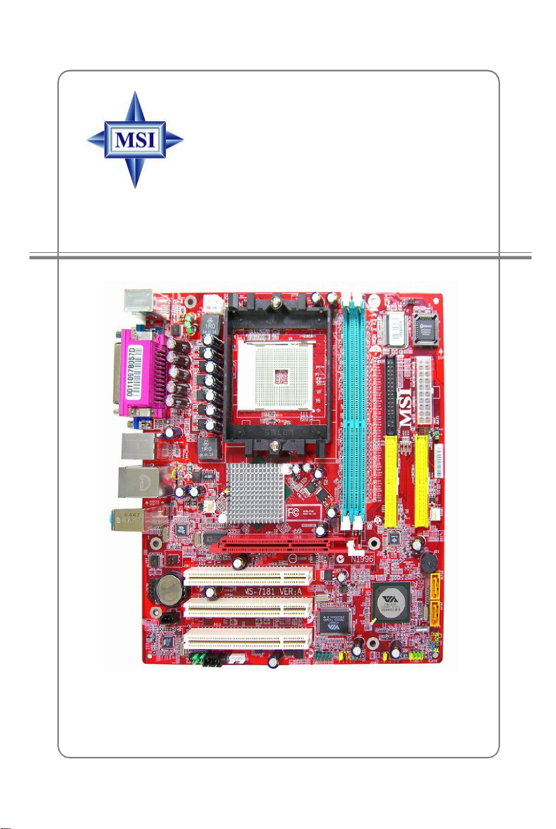
K8MM3 Series
MS-7181 (v2.X) Micro-ATX Mainboard
G52-M7181X4
i
Page 2
FCC-B Radio Frequency Interference Statement
This equipment has been tested
and found to comply with the
limits for a class B digital device,
pursuant to part 15 of the FCC
rules. These limits are designed
to provide reasonable protection against harmful interference in a residential installation.
This equipment generates, uses and can radiate radio frequency energy and, if not
installed and used in accordance with the instruction manual, may cause harmful
interference to radio communications. However, there is no guarantee that interference
will not occur in a particular installation. If this equipment does cause harmful
interference to radio or television reception, which can be determined by turning the
equipment off and on, the user is encouraged to try to correct the interference by one
or more of the measures listed below.
=Reorient or relocate the receiving antenna.
=Increase the separation between the equipment and receiver.
=Connect the equipment into an outlet on a circuit different from that to which the
receiver is connected.
=Consult the dealer or an experienced radio/television technician for help.
Notice 1
The changes or modifications not expressly approved by the party responsible for
compliance could void the user’s authority to operate the equipment.
Notice 2
Shielded interface cables and A.C. power cord, if any, must be used in order to
comply with the emission limits.
VOIR LA NOTICE D’INSTALLATION AVANT DE RACCORDER AU RESEAU.
Micro-Star International
MS-7181
This device complies with Part 15 of the FCC Rules. Operation is subject to the
following two conditions:
(1) this device may not cause harmful interference, and
(2) this device must accept any interference received, including interference that
may cause undesired operation
ii
Page 3

Copyright Notice
The material in this document is the intellectual property of MICRO-STAR
INTERNATIONAL. We take every care in the preparation of this document, but no
guarantee is given as to the correctness of its contents. Our products are under
continual improvement and we reserve the right to make changes without notice.
Trademarks
All trademarks are the properties of their respective owners.
AMD, Athlon™ 64 and Athlon™ FX are registered trademarks of AMD Corporation.
Intel® and Pentium® are registered trademarks of Intel Corporation.
PS/2 and OS®/2 are registered trademarks of International Business Machines
Corporation.
Microsoft is a registered trademark of Microsoft Corporation. Windows® 98/2000/NT/
XP are registered trademarks of Microsoft Corporation.
NVIDIA, the NVIDIA logo, DualNet, and nForce are registered trademarks or trademarks of NVIDIA Corporation in the United States and/or other countries.
Netware® is a registered trademark of Novell, Inc.
Award® is a registered trademark of Phoenix Technologies Ltd.
AMI® is a registered trademark of American Megatrends Inc.
Kensington and MicroSaver are registered trademarks of the Kensington Technology
Group.
PCMCIA and CardBus are registered trademarks of the Personal Computer Memory
Card International Association.
Revision History
Revision Revision History Date
V1.0 First release for PCB 1.X May 2005
V1.1 Add WEEE Statement Sept. 2005
V2.0 First release for PCB 2.X January 2006
with VIA K8M800 & VT8237R
with VIA K8M800 & VT8237R/ VT8237R Plus
with VIA K8M800 & VT8237R/ VT8237R Plus
iii
Page 4

Technical Support
If a problem arises with your system and no solution can be obtained from the user’ s
manual, please contact your place of purchase or local distributor. Alternatively,
please try the following help resources for further guidance.
† Visit the MSI homepage & FAQ site for technical guide, BIOS updates, driver
updates, and other information: http://www.msi.com.tw & http://www.msi.
com.tw/program/service/faq/faq/esc_faq_list.php
† Contact our technical staff at: support@msi.com.tw
Safety Instructions
1. Always read the safety instructions carefully.
2. Keep this User’s Manual for future reference.
3. Keep this equipment away from humidity.
4. Lay this equipment on a reliable flat surface before setting it up.
5. The openings on the enclosure are for air convection hence protects the equipment from overheating. Do not cover the openings.
6. Make sure the voltage of the power source and adjust properly 110/220V before connecting the equipment to the power inlet.
7. Place the power cord such a way that people can not step on it. Do not place
anything over the power cord.
8. Always Unplug the Power Cord before inserting any add-on card or module.
9. All cautions and warnings on the equipment should be noted.
10. Never pour any liquid into the opening that could damage or cause electrical
shock.
11. If any of the following situations arises, get the equipment checked by a service
personnel:
† The power cord or plug is damaged.
† Liquid has penetrated into the equipment.
† The equipment has been exposed to moisture.
† The equipment has not work well or you can not get it work according to
User’s Manual.
† The equipment has dropped and damaged.
† The equipment has obvious sign of breakage.
12. Do not leave this equipment in an environment unconditioned, storage
temperature above 600 C (1400F), it may damage the equipment.
CAUTION: Danger of explosion if battery is incorrectly replaced.
Replace only with the same or equivalent type recommended by the
manufacturer.
iv
Page 5

WEEE Statement
v
Page 6
vi
Page 7
vii
Page 8

CONTENTS
FCC-B Radio Frequency Interference Statement..........................................................ii
Copyright Notice..............................................................................................................iii
Revision History..............................................................................................................iii
Technical Support..........................................................................................................iv
Safety Instructions.........................................................................................................iv
WEEE Statement........................................................................................................v
Chapter 1. Getting Started....................................................................................1-1
Mainboard Specifications...................................................................................1-2
Mainboard Layout................................................................................................1-4
Packing Contents.................................................................................................1-5
Chapter 2. Hardware Setup..................................................................................2-1
Quick Components Guide...................................................................................2-2
Central Processing Unit: CPU.............................................................................2-3
Memory Speed/CPU FSB Support Matrix...................................................2-3
CPU Installation Procedures for Socket 754.............................................2-4
Installing AMD Athlon64 CPU Cooler Set....................................................2-5
Memory.................................................................................................................2-6
Introduction to DDR SDRAM.......................................................................2-6
DDR DIMM Module Combination..................................................................2-7
Installing DDR Modules................................................................................2-7
Power Supply......................................................................................................2-8
ATX 20-Pin Power Connector: JWR1........................................................2-8
ATX 12V Power Connector: JPW1............................................................2-8
Back Panel...........................................................................................................2-9
View of the Back Panel..............................................................................2-9
Serial Port: COM1........................................................................................2-9
Mouse Connector......................................................................................2-10
Keyboard Connector.................................................................................2-10
VGA Connector.........................................................................................2-10
USB Ports....................................................................................................2-11
RJ-45 LAN Jack..........................................................................................2-11
IEEE 1394 Port............................................................................................2-12
Audio Port Connectors..............................................................................2-12
Parallel Port................................................................................................2-13
Connectors........................................................................................................2-14
Floppy Disk Drive Connector: FDD1........................................................2-14
viii
Page 9

Fan Power Connectors: CPUFAN1, SFAN1............................................2-14
Hard Disk Connectors: IDE1 & IDE2.........................................................2-15
Serial Port Header: JCOM1 (Optional).....................................................2-15
Serial ATA/Serial ATA RAID Connectors controlled by VT8237R/VT8237R
Plus: SATA1 & SATA2...............................................................................2-16
Front Panel Connectors: JFP1 & JFP2.....................................................2-17
Chassis Intrusion Switch Connector: JCI1..............................................2-17
Aux Line-In Connector: JAUX1................................................................2-18
CD-In Connector: JCD1.............................................................................2-18
Front USB Connectors: JUSB1 & JUSB2.................................................2-18
Front Panel Audio Connector: JAUD1......................................................2-19
IrDA Infrared Module Header: JIR1...........................................................2-19
IEEE 1394 Connector: J1394_1................................................................2-20
SPDIF-Out Connector: JSP1.....................................................................2-20
Jumpers..............................................................................................................2-21
Clear CMOS Jumper: JBAT1.....................................................................2-21
Slots....................................................................................................................2-22
AGP (Accelerated Graphics Port) Slot....................................................2-22
PCI (Peripheral Component Interconnect) Slots......................................2-22
PCI Interrupt Request Routing...................................................................2-22
Chapter 3. BIOS Setup............................................................................................3-1
Entering Setup.....................................................................................................3-2
Selecting the First Boot Device..................................................................3-2
Control Keys................................................................................................3-3
Getting Help..................................................................................................3-3
The Main Menu.....................................................................................................3-4
Standard CMOS Features...................................................................................3-6
Advanced BIOS Features...................................................................................3-8
Advanced Chipset Features............................................................................3-10
Integrated Peripherals.......................................................................................3-14
Power Management Setup...............................................................................3-17
PNP/PCI Configurations.....................................................................................3-20
H/W Monitor........................................................................................................3-22
Load Optimized Defaults...................................................................................3-24
BIOS Setting Password....................................................................................3-25
Chapter 4. Introduction to DigiCell.....................................................................4-1
Main......................................................................................................................4-2
Introduction:.................................................................................................4-2
ix
Page 10

H/W Diagnostic....................................................................................................4-4
Communication.....................................................................................................4-5
Software Access Point.......................................................................................4-6
Terminology..................................................................................................4-6
Access Point Mode.....................................................................................4-7
WLAN Card Mode........................................................................................4-8
Live Update..........................................................................................................4-9
MEGA STICK.......................................................................................................4-10
Basic Function...........................................................................................4-10
Non-Unicode programs supported...........................................................4-12
PC Alert...............................................................................................................4-14
Audio Speaker Setting......................................................................................4-15
Power on Agent.................................................................................................4-17
Power On...................................................................................................4-17
Power Off / Restart...................................................................................4-18
Start With....................................................................................................4-18
Auto Login..................................................................................................4-19
Chapter 5. VIA VT8237R/ VT8237R Plus SATA RAID Introduction................5-1
Introduction..........................................................................................................5-2
RAID Basics.................................................................................................5-2
RAID 0 (Striping)..........................................................................................5-2
RAID 1 (Mirroring)........................................................................................5-2
BIOS Configuration..............................................................................................5-3
Create Disk Array........................................................................................5-4
Delete Disk Array.........................................................................................5-6
Create and Delete Spare Hard Drive.........................................................5-7
View Serial Number of Hard Drive.............................................................5-7
Duplicate Critical RAID 1 Array...................................................................5-8
Rebuild Broken RAID 1 Array.....................................................................5-8
Installing RAID Software & Drivers.................................................................5-10
Install Driver in Windows OS....................................................................5-10
Installation of VIA SATA RAID Drvier and Utility.......................................5-11
Using VIA RAID Tool..........................................................................................5-13
Chapter 6. Using 2-, 4- & 6-Channel Audio Function.....................................6-1
Installing the Audio Driver...................................................................................6-2
Installation for Windows 98SE/ME/2000/XP..............................................6-2
Special Notice during Installation...............................................................6-2
x
Page 11

Software Configuration......................................................................................6-4
Speaker........................................................................................................6-4
Mixer.............................................................................................................6-5
Recording.....................................................................................................6-5
SPDIF.............................................................................................................6-6
Speaker Test................................................................................................6-6
Information....................................................................................................6-7
Using 2-, 4- & 6- Channel Audio Function.........................................................6-8
xi
Page 12

Getting Started
Chapter 1. Getting
Started
Getting Started
Thank you for purchasing the K8MM3 (MS-7181 v2.x) series, an
excellent Micro-ATX mainboard from MSI. Based on the innovative VIA
K8M800 and VIA VT8237R/ VT8237R Plus chipsets for optimal system efficiency, the K8MM3 serias mainboard accommodates latest AMD
K8 processor in the 754-pin lidded ceramic micro PGA package, and
supports up to 2 DIMMs to provide the maximum of 2 GB memory capacity.
This mainboard provides a high professional desktop platform solution.
1-1
Page 13

MS-7181 Micro-ATX Mainboard
Mainboard Specifications
CPU
† Supports 64-bit AMD® K8 Athlon 64/ Sempron processor (Socket 754).
† Supports 3700+ or higher CPU.
Chipset
† VIA K8M800 Chipset
-HyperTransportTM connection to AMD K8 Athlon64/ Sempron processor
-8 or 16 bit control/address/data transfer both directions
-800/600/400/200 MHz “Double Data Rate” operation both direction
-AGP v3.0 compliant with 8x transfer mode
-Graphic integrated
† VIA VT8237R/ VT8237R Plus Chipset
- Integrated Hardware Sound Blaster/Direct Sound AC97 audio
- Ultra DMA 66/100/133 master mode PCI EIDE controller
- ACPI& PC2001 compliant enhanced power management
- Supports dual channel native SATA controller up to 150MB/s
- Supports SATA RAID 0 or RAID 1
- Supports 8 USB2.0 ports
- Supports SATA2 Device (for VT8237R Plus only)
Main Memory
† Supports DDR266/333/400 DDR SDRAM, and unbuffered DIMMs for two
184- pin DDR DIMMs.
† Supports DIMM sizes up to 2GB of memory in total.
Slots
† One AGP 8x/4x slot.
† Three 32-bit/33 MHz PCI slots.
On-Board IDE
† An IDE controller on the VT8237R/ VT8237R Plus chipset provides IDE HDD/CD-
ROM with PIO, Bus Master and Ultra DMA133/100/66 operation modes.
- Can connect up to four Ultra ATA drives.
† Serial ATA/150 controller integrated in VT8237R/ VT8237R Plus.
- Up to 150MB/sec transfer speeds. (VT8237R Plus supports SATA2 device.)
- Can connect up to two Serial ATA drives.
- Supports RAID 0 or 1
1-2
Page 14

Getting Started
On-Board Peripherals
† On-Board Peripherals include:
- 1 floppy port supports 1 FDDs with 360K, 720K, 1.2M, 1.44M and 2.88Mbytes
- 2 serial ports (Rear * 1/ Front * 1)
- 1 VGA port onboard
- 1 parallel port supports SPP/EPP/ECP mode
- 1 IrDA pinheader (optional)
- 1 CD-In pinheader
- 1 Aux-In pinheader
- 1SPDIF out pinheader (optional)
- 1 audio port (Line-in/Line-out/MIC)
- 8 USB 1.1/2.0 ports (Rear * 4/ Front * 4)
IEEE 1394 (Optional)
† Supports up to 2 * 1394 ports (Rear * 1/ onboard header * 1).
Transfer rate is up to 400Mbps
† Controlled by VIA 6307 or 6308P chipset
Audio
† AC’97 link controller integrated in VIA VT8237R/ VT8237R Plus.
† 6 channels software audio codec VIA VT1617A
- Compliance with AC97 v2.3 Spec.
- Meet PC2001 audio performance requirement.
LAN
† VIA VT8237R/ VT8237R Plus MAC + VIA 6103 Ethernet PHY
- Supports 10/100Mb/s auto-negotiation operation.
- Compliant with PCI v2.2 and PC99 standard.
- Supports ACPI Power Management.
BIOS
† The mainboard BIOS provides “Plug & Play” BIOS which detects the peripheral
devices and expansion cards of the board automatically.
† The mainboard provides a Desktop Management Interface (DMI) function which
records your mainboard specifications.
Dimension and Mounting
† Micro-ATX Form Factor: 24.4 cm (L) x 21.5 cm (W).
† 6 mounting holes
1-3
Page 15

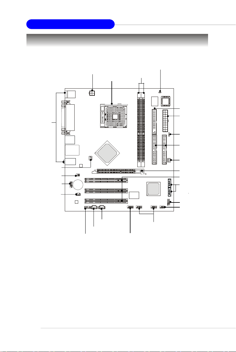
MS-7181 Micro-ATX Mainboard
AGP1
IDE 1IDE
2
SATA2FDD 1JWR
2
BIOS
JBAT1WinbondW83627EHG
JSP1
JIR1
(optional)
VT6307/6308P
VT8237R/Plus
Mainboard Layout
Top : mouse
Bottom: keyboard
Top :
Parallel Port
Bottom:
COM Port
VGA Port
Top :1394 port
B:USB ports
Top: LAN Jack
Bottom: USB
ports
T:
Line-In
Line-Out
M:
B:Mic
JCOM1
VT1617A
JPW1
VIA
K8M800
CPUFAN1
VIA
VT6103L
PCI1
BATT
+
PCI2
PCI3
VIA
JAUD1 JCD1 JAUX1 J1394_1
DDR1DDR2
VIA
JUSB2 JUSB1
JCI1
SFAN1
VIA
SATA1
JFP1
JFP2
K8MM3 (MS-7181 v2.X) Series Mainboard
1-4
Page 16
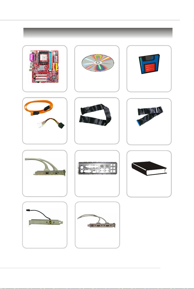
Packing Contents
Getting Started
MSI motherboard
SATA Cable/
Power Cable (Optional)
1394 Cable
(Optional)
MSI Driver/Utility CD
Flat Cable of
Floppy Disk
SATA RAID Driver
Diskette
Flat Cable of
IDE Devices
User’ s GuideBack IO Shield
SPDIF-Bracket
(Optional)
* The pictures are for reference only and may vary from the packing contents of the
product you purchased.
USB Bracket
(Optional)
1-5
Page 17

Hardware Setup
Chapter 2. Hardware
Setup
Hardware Setup
This chapter provides you with the information about hardware setup
procedures. While doing the installation, be careful in holding the components and follow the installation procedures. For some components,
if you install in the wrong orientation, the components will not work
properly.
Use a grounded wrist strap before handling computer components.
Static electricity may damage the components.
2-1
Page 18
MS-7181 Micro-ATX Mainboard
Quick Components Guide
I/O Ports,
p.2-9
CPUFAN1,
p.2-14
JIR1, p.2-19
JCOM1, p.2-18
JSP1, p.2-20
JPW1, p.2-8
CPU, p.2-3
JAUX1, p.2-18
JCD1, p.2-18
JAUD1, p.2-19
DIMM1-2, p.2-6
JUSB1/2, p.2-15
J1394_1, p.2-20
JCI1, p.2-18
FDD1, p.2-14
JWR1, p.2-8
JBAT1, p.2-21
IDE1, IDE2,
p.2-15
SFAN1,
p.2-14
AGP slot, p.2-22
PCI slots, p.2-22
SATA1/2, p.2-16
JFP1, p.2-17
JFP2, p.2-17
2-2
Page 19
Hardware Setup
Central Processing Unit: CPU
The mainboard supports AMD® Athlon64/ Sempron processor. The mainboard uses a
CPU socket called Socket-754 for easy CPU installation. When you are installing the
CPU, make sure the CPU has a heat sink and a cooling fan attached on the
top to prevent overheating. If you do not have the heat sink and cooling fan,
contact your dealer to purchase and install them before turning on the computer.
Memory Speed/CPU FSB Support Matrix
DDR 266
FSB 800
MSI Reminds You...
Overheating
Overheating will seriously damage the CPU and system, always make
sure the cooling fan can work properly to protect the CPU from
overheating.
Replacing the CPU
While replacing the CPU, always turn off the ATX power supply or
unplug the power supply’s power cord from grounded outlet first to
ensure the safety of CPU.
OK OK
DDR 333
DDR 400
OK
2-3
Page 20
MS-7181 Micro-ATX Mainboard
Gold arrow
Gold arrow
Gold arrow
Correct CPU placement
Incorrect CPU placement
Close
Press down
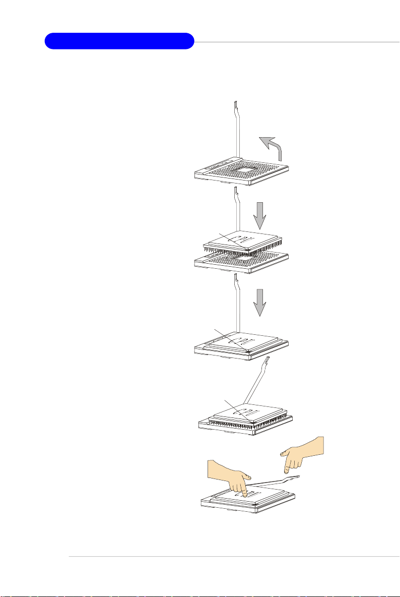
CPU Installation Procedures for Socket 754
1. Please turn off the power and
unplug the power cord before
installing the CPU.
Open Lever
2. Pull the lever sideways away
from the socket. Make sure to
raise the lever up to a 90-degree angle.
3.Look for the gold arrow. The gold
arrow should point as picture
shown. The CPU can only fit in
the correct orientation.
4.If the CPU is correctly installed,
the pins should be completely
embedded into the socket and
can not be seen. Please note
that any violation of the correct
installation procedures may
cause permanent damages to
your mainboard.
5. Press the CPU down firmly into
the socket and close the lever.
As the CPU is likely to move while
the lever is being closed, always close the lever with your
fingers pressing tightly on top of
the CPU to make sure the CPU is
properly and completely embedded into the socket.
Sliding
Plate
90 degree
O
X
the CPU
Lever
2-4
Page 21

Hardware Setup
Installing AMD Athlon64 CPU Cooler Set
When you are installing the CPU, make sure the CPU has a heat sink and a
cooling fan attached on the top to prevent overheating. If you do not have the
heat sink and cooling fan, contact your dealer to purchase and install them before
turning on the computer.
1.Position the cooling set onto the
retention mechanism. Hook one
end of the clip to hook first.
4.Fasten down the lever.
2.Press down the other end of the
clip to fasten the cooling set on
the top of the retention
mechanism.
3.Locate the Fix Lever, Safety Hook
and the Fixed Bolt. Lift up the intensive fixed lever.
Safety
Fixed Lever
Fixed Bolt
5.Make sure the safety hook
completely clasps the fixed
bolt of the retention
mechanism.
6. Connect the fan power cable
from the mounted fan to the
CPUFAN1 connector on the
board
MSI Reminds You...
While disconnecting the Safety
Hook from the fixed bolt, it is
necessary to keep an eye on
your fingers, because once the
Safety Hook is disconnected
from the fixed bolt, the fixed
lever will spring back instantly.
2-5
Page 22
MS-7181 Micro-ATX Mainboard
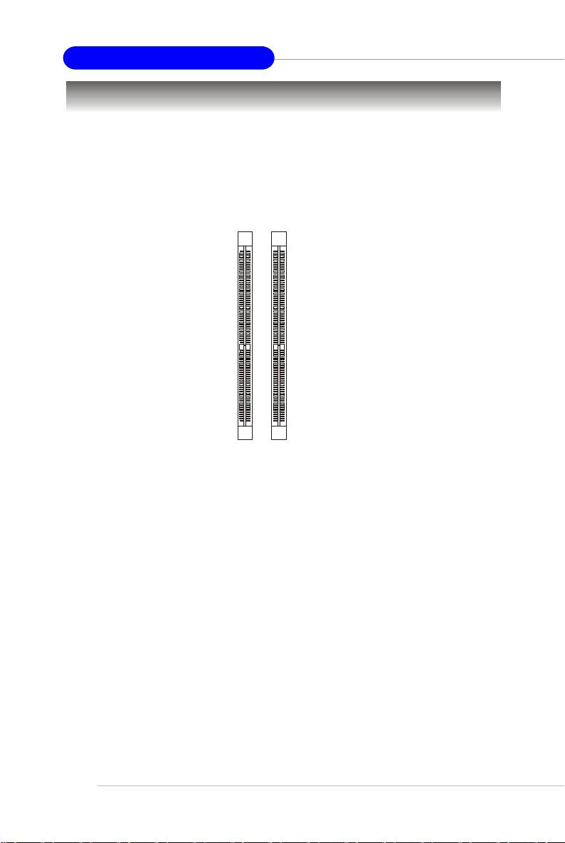
Memory
The mainboard provides two slots for 184-pin DDR SDRAM DIMM (Double In-Line
Memory Module) modules and supports up to 2GB memory size. You can install
PC3200/DDR400, PC2700/DDR333 & PC2100/DDR266 modules on the DDR DIMM slots
(DDR 1~2).
For the updated supporting memory modules, please visit http://www.msi.com.tw/
program/products/mainboard/mbd/pro_mbd_trp_list.php.
DDR DIMM Slots
(DIMM1~2)
Introduction to DDR SDRAM
DDR (Double Data Rate) SDRAM is similar to conventional SDRAM, but doubles the
rate by transferring data twice per cycle. It uses 2.5 volts as opposed to 3.3 volts
used in SDR SDRAM, and requires 184-pin DIMM modules rather than 168-pin DIMM
modules used by SDR SDRAM. High memory bandwidth makes DDR an ideal solution
for high performance PC, workstations and servers.
2-6
Page 23
Hardware Setup
DDR DIMM Module Combination
Install at least one DIMM module on the slots. Memory modules can be installed on the
slots in any order. You can install either single- or double-sided modules to meet your
own needs.
Memory modules can be installed in any combination as follows:
Slot Memory Module Total Memory
DIMM 1
S/D 64MB~1GB
(Bank 0 & 1)
DIMM 2
S/D 64MB~1GB
(Bank 2 & 3)
Maximum System Memory Supported
S: Single Side D: Double Side
64MB~2GB
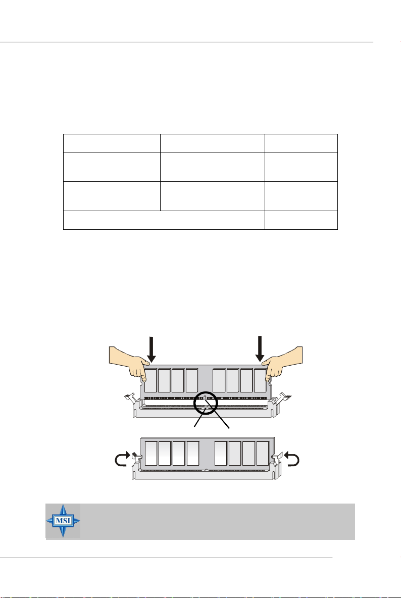
Installing DDR Modules
1. The DDR DIMM has only one notch on the center of module. The module will only
fit in the right orientation.
2. Insert the DIMM memory module vertically into the DIMM slot. Then push it in until
the golden finger on the memory module is deeply inserted in the socket.
3. The plastic clip at each side of the DIMM slot will automatically close.
Volt
MSI Reminds You...
You can barely see the golden finger if the module is properly inserted
in the socket.
Notch
2-7
Page 24
MS-7181 Micro-ATX Mainboard
Power Supply
The mainboard supports ATX power supply for the power system. Before inserting
the power supply connector, always make sure that all components are installed
properly to ensure that no damage will be caused.
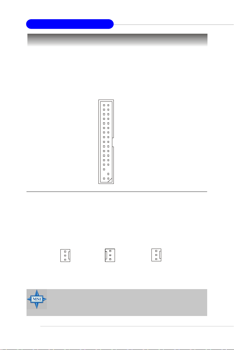
ATX 20-Pin Power Connector: JWR1
This connector allows you to connect to an ATX power supply. To connect to the ATX
power supply, make sure the plug of the power supply is inserted in the proper
orientation and the pins are aligned. Then push down the power supply firmly into the
connector.
10
20
1
11
JWR1
ATX 12V Power Connector: JPW1
This 12V power connector is used to provide power to the CPU.
JWR1 Pin Definition
PIN SIGNAL
1 3.3V
2 3.3V
3 GND
4 5V
5 GND
6 5V
7 GND
8 PW_OK
9 5V_SB
10 12V
PIN SIGNAL
11 3.3V
12 -12V
13 GND
14 PS_ON
15 GND
16 GND
17 GND
18 -5V
19 5V
20 5V
2-8
4 2
3
JPW1
1
PIN SIGNAL
1 GND
2 GND
3 12V
4 12V
JPW1 Pin Definition
MSI Reminds You...
There is a mechanism of this mainboard to protect it from being
damaged. The power will shut down automatically in two conditions: the
temperature of CPU reaches 100oC, or the low voltage occurs during
booting up. Please follow the instructions below for this issue:
1. The power LED will blink continously. You should unplug the power
cord or turn off the power switch.
2.After the power LED stop blinking, plug on the power cord or turn on
the power switch, then you can reboot your system again.
Page 25
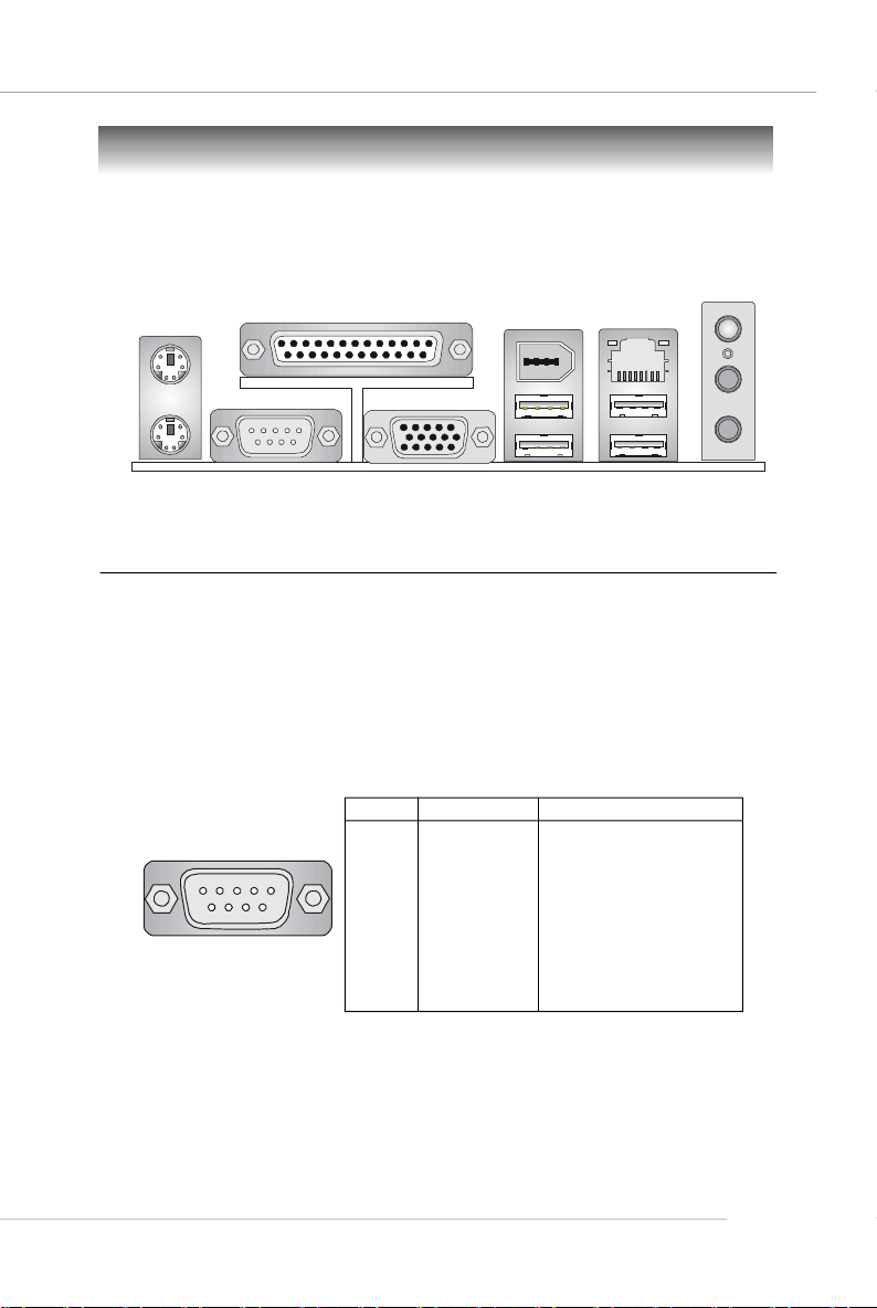
Back Panel
View of the Back Panel
The back panel provides the following connectors:
Parallel
Mouse
(optional)
1394
Port
Hardware Setup
L-in
LAN
Keyboard
COM 1
VGA Port
USB Ports
USB Ports
L-out
MIC
Serial Port: COM1
The mainboard provides one 9-pin mail DIN connector as serial port COM1. The serial
port is a 16550A high speed communication port that sends/receives 16 bytes FIFOs.
You can attach a serial mouse or other serial device directly to it.
Pin Definition
PIN SIGNAL DESCRIPTION
1 2 3 4 5
6 7 8 9
COM1
1 DCD Data Carry Detect
2 SIN Serial In or Receive Data
3 SOUT Serial Out or Transmit Data
4 DTR Data Terminal Ready
5 GND Ground
6 DSR Data Set Ready
7 RTS Request To Send
8 CTS Clear To Send
9 RI Ring Indicate
2-9
Page 26
MS-7181 Micro-ATX Mainboard
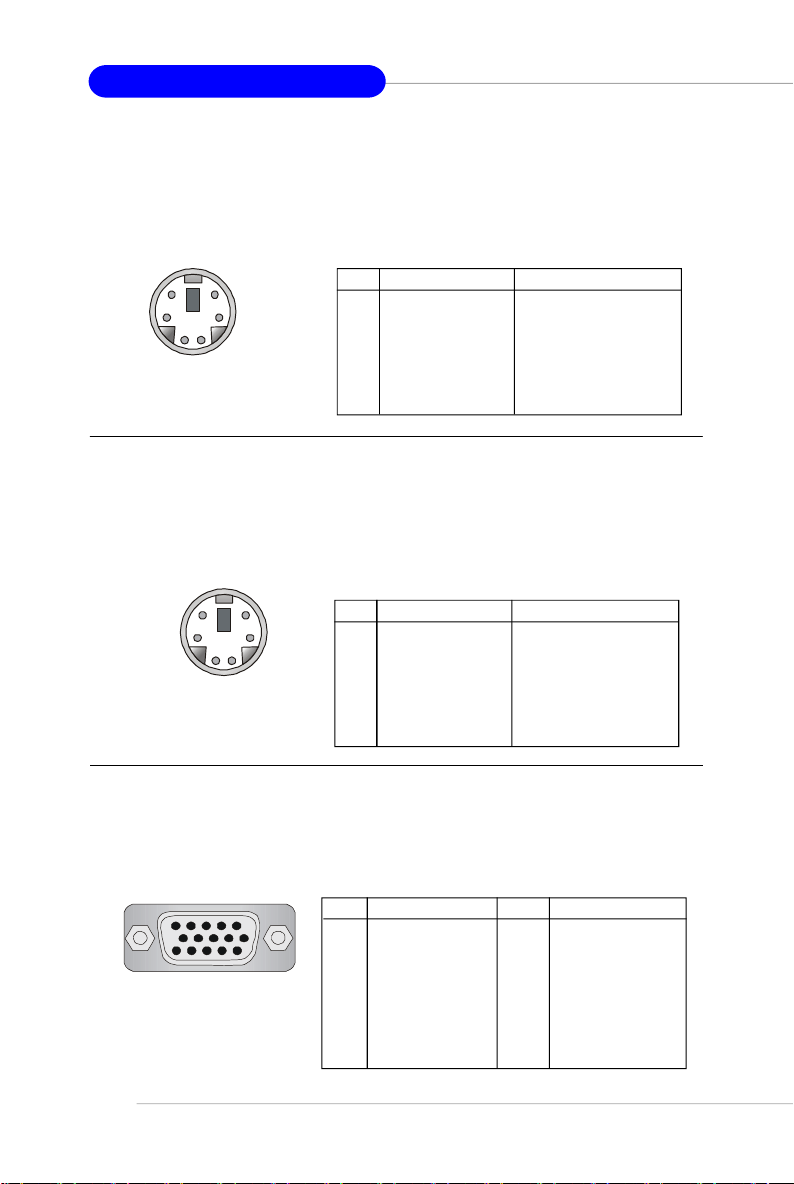
Mouse Connector
The mainboard provides a standard PS/2® mouse mini DIN connector for attaching a
PS/2® mouse. You can plug a PS/2® mouse directly into this connector. The connector
location and pin assignments are as follows.
Pin Definition
6
4
2
5
1
PS/2 Mouse
(6-pin Female)
3
PIN SIGNAL DESCRIPTION
1 Mouse Data Mouse data
2 NC No connection
3 GND Ground
4 VCC +5V
5 Mouse Clock Mouse clock
6 NC No connection
Keyboard Connector
The mainboard provides a standard PS/2® keyboard mini DIN connector for attaching
a PS/2® keyboard. You can plug a PS/2® keyboard directly into this connector. The
connector location and pin assignments are as follows.
Pin Definition
6
4
2
PS/2 Keyboard
(6-pin Female)
5
3
1
PIN SIGNAL DESCRIPTION
1 Keyboard Data Keyboard data
2 NC No connection
3 GND Ground
4 VCC +5V
5 Keyboard Clock Keyboard clock
6 NC No connection
VGA Connector
The mainboard provides a DB 15-pin female connector to connect a VGA monitor.
Pin Definition
Pin Signal Description
9 +5V
10 GND
11 N/C
12 SDA
13 Horizontal Sync
14 Vertical Sync
15 SCL
VGA Connector
2-10
5
15
(DB 15-pin)
1
11
Pin Signal Description
1 RED
2 GREEN
3 BLUE
4 N/C
5 GND
6 GND
7 GND
8 GND
Page 27
Hardware Setup
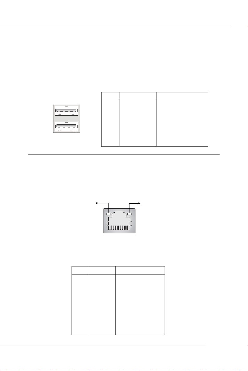
USB Ports
The mainboard provides a UHCI (Universal Host Controller Interface) Universal Serial
Bus root for attaching USB devices such as keyboard, mouse or other USB-compatible devices. You can plug USB devices directly into the ports.
Pin Definition
PIN SIGNAL DESCRIPTION
1 2 3 4
5 6 7 8
USB Ports
1 VCC +5V
2 -Data 0 Negative Data Channel 0
3 +Data 0 Positive Data Channel 0
4 GND Ground
5 VCC +5V
6 -Data 1 Negative Data Channel 1
7 +Data 1 Positive Data Channel 1
8 GND Ground
RJ-45 LAN Jack
The mainboard provides one standard RJ-45 jack for connection to Local Area Network (LAN). You can connect a network cable to the LAN jack.
Activity Indicator
8 1
RJ-45 LAN Jack
10/100 LAN Pin Definition
PIN SIGNAL DESCRIPTION
1 TDP Transmit Differential Pair
2 TDN Transmit Differential Pair
3 RDP Receive Differential Pair
4 NC Not Used
5 NC Not Used
6 RDN Receive Differential Pair
7 NC Not Used
8 NC Not Used
Link Indicator
2-11
Page 28
MS-7181 Micro-ATX Mainboard
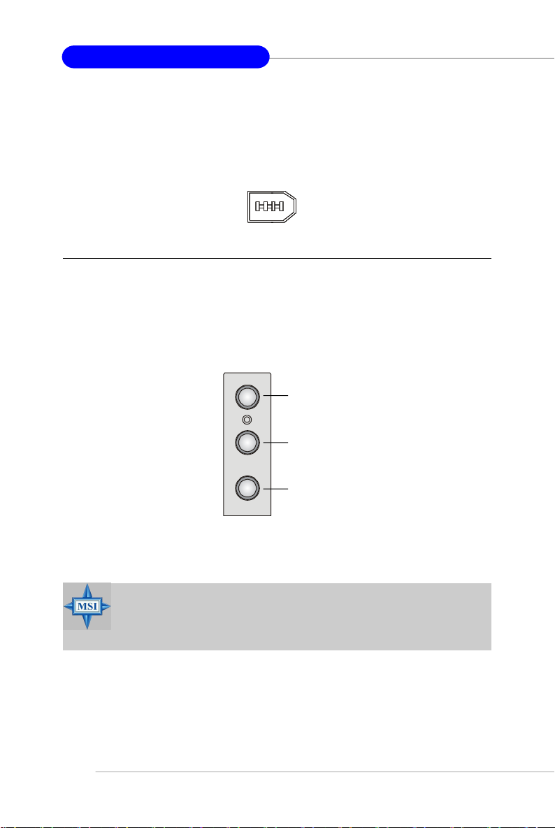
IEEE 1394 Port (Optional)
The back panel provides one standard IEEE 1394 port. The IEEE1394 high-speed
serial bus complements USB by providing enhanced PC connectivity for a wide range
of devices, including consumer electronics audio/video (A/V) appliances, storage
peripherals, other PCs, and portable devices.
IEEE1394 Port
Audio Port Connectors
Line Out is a connector for Speakers or Headphones. Line In is used for external
CD player, Tape player, or other audio devices. Mic is a connector for microphones.
Line In
Line Out
2-12
MIC
MSI Reminds You...
For advanced audio application, VIA VT1617 audio chip is provided
to offer support for 6-channel audio operation and can turn rear
audio connectors from 2-channel to 4-/6-channel audio.
Page 29
Hardware Setup
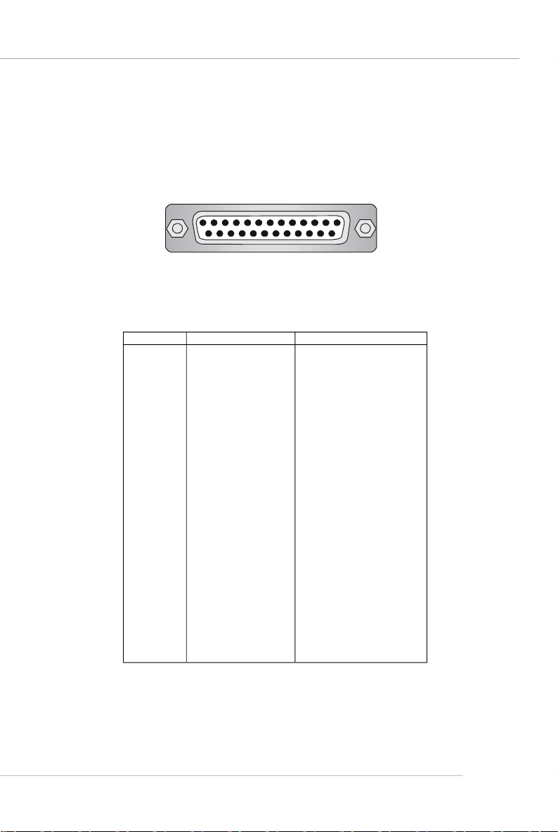
Parallel Port
The mainboard provides a 25-pin female centronic connector as LPT. A parallel port
is a standard printer port that supports Enhanced Parallel Port (EPP) and Extended
Capabilities Parallel Port (ECP) mode.
13 1
25
14
Pin Definition
PIN SIGNAL DESCRIPTION
1 STROBE Strobe
2 DATA0 Data0
3 DATA1 Data1
4 DATA2 Data2
5 DATA3 Data3
6 DATA4 Data4
7 DATA5 Data5
8 DATA6 Data6
9 DATA7 Data7
10 ACK# Acknowledge
11 BUSY Busy
12 PE Paper End
13 SELECT Select
14 AUTO FEED# Automatic Feed
15 ERR# Error
16 INIT# Initialize Printer
17 SLIN# Select In
18 GND Ground
19 GND Ground
20 GND Ground
21 GND Ground
22 GND Ground
23 GND Ground
24 GND Ground
25 GND Ground
2-13
Page 30
MS-7181 Micro-ATX Mainboard
Connectors
The mainboard provides connectors to connect FDD, IDE HDD, front panel of the
system case, audio ports, USB Ports, and CPU/System FANs.
Floppy Disk Drive Connector: FDD1
The mainboard provides a standard floppy disk drive connector that supports 360KB,
720KB, 1.2MB, 1.44MB and 2.88MB floppy disk types.
FDD1
Fan Power Connectors: CPUFAN1, SFAN1
The CPUFAN1 (processor fan) and SFAN1 (system fan) support system cooling fan
with +12V. It supports 3-pin head connector. When connecting the wire to the
connectors, always take note that the red wire is the positive and should be connected to the +12V, the black wire is Ground and should be connected to GND. If the
mainboard has a System Hardware Monitor chipset on-board, you must use a specially designed fan with speed sensor to take advantage of the CPU fan control.
SENSOR
+12V
GND
Fan Connector
Pin Definition
2-14
CPUFAN1
SFAN1
MSI Reminds You...
1. Always consult the vendors for proper CPU cooling fan.
2. CPUFAN1 supports Smart Fan control, you may set up the smart fan
control functions in the BIOS setup.
Page 31

Hardware Setup
Hard Disk Connectors: IDE1 & IDE2
The mainboard provides a 32-bit Enhanced PCI IDE and Ultra DMA 33/66/100/133
controller that supports PIO mode 0 ~ 4, Bus Master, and Ultra DMA 33/66/100/133
function. You can connect up to four hard disk drives, CD-ROM drives, 120MB floppy
disk drive (reserved for future BIOS), and other devices.
IDE2IDE1
MSI Reminds You...
If you install two hard disks on cable, you must configure the second
drive to Slave mode by setting its jumper. Refer to the hard disk
documentation supplied by hard disk vendors for jumper setting
instructions.
Serial Port Header: JCOM1 (Optional)
The mainboard offers one 9-pin header as serial port. The port is a 16550A high
speed communication port that sends/receives 16 bytes FIFOs. You can attach a
serial mouse or other serial device directly to it.
Pin Definition
PIN SIGNAL DESCRIPTION
1
5
JCOM1
6
9
1 DCD Data Carry Detect
2 SIN Serial In or Receive Data
3 SOUT Serial Out or Transmit Data
4 DTR Data Terminal Ready)
5 GND Ground
6 DSR Data Set Ready
7 RTS Request To Send
8 CTS Clear To Send
9 RI Ring Indicate
2-15
Page 32

MS-7181 Micro-ATX Mainboard
Serial ATA/Serial ATA RAID Connectors controlled by VT8237R/
VT8237R Plus: SATA1 & SATA2
The Southbridge of this mainboard is VIA VT8237R/ VT8237R Plus which supports
two serial connectors SATA1& SATA2.
SATA1 & SATA2 are dual high-speed Serial ATA interface ports. Each supports 1
generation serial ATA data rates of 150 MB/s. Both connectors are fully compliant
with Serial ATA 1.0 specifications. Each Serial ATA connector can connect to 1 hard
disk device. Please refer to VIA VT8237R/VT8237R Plus SATA RAID Introduction for
detail software installation procedure.
SATA2
17
17
SATA1 & SATA2 Pin Definition
Pin Signal Pin Signal
1 GND 2 TXP
3 TXN 4 GND
5 RXN 6 RXP
7 GND
st
SATA1
Optional Serial ATA cable
MSI Reminds You...
Please do not fold the serial ATA cable in a 90-degree angle, which will
cause the loss of data during the transmission.
2-16
Take out the dust cover and
connect to the hard disk
devices
Connect to SATA1 or SATA2
Page 33

Hardware Setup
Front Panel Connectors: JFP1 & JFP2
The mainboard provides two front panel connectors for electrical connection to the
front panel switches and LEDs. JFP1 is compliant with Intel® Front Panel I/O Connectivity Design Guide.
Power
7
8
LED
Speaker
1
2
12
Power
LED
Power
Switch
10
9
JFP2
JFP1
HDD
LED
Reset
Switch
JFP1 Pin Definition
PIN SIGNAL DESCRIPTION
1 HD_LED_P Hard disk LED pull-up
2 FP PWR/SLP MSG LED pull-up
3 HD_LED_N Hard disk active LED
4 FP PWR/SLP MSG LED pull-up
5 RST_SW_N Reset Switch low reference pull-down to GND
6 PWR_SW_P Power Switch high reference pull-up
7 RST_SW_P Reset Switch high reference pull-up
8 PWR_SW_N Power Switch low reference pull-down to GND
9 RSVD_DNU Reserved. Do not use.
JFP2 Pin Definition
PIN SIGNAL PIN SIGNAL
1 GND 2 SPK3 SLED 4 BUZ+
5 PLED 6 BUZ-
7 NC 8 SPK+
Chassis Intrusion Switch Connector: JCI1
This connector is connected to a 2-pin chassis switch. If the
chassis is opened, the switch will be short. The system will record
this status and show a warning message on the screen. To clear
the warning, you must enter the BIOS utility and clear the record.
CINTRU GND
1 2
JCI1
2-17
Page 34

MS-7181 Micro-ATX Mainboard
Aux Line-In Connector: JAUX1
The connector is for DVD add-on card with Line-in connector.
GND
R
L
JAUX1
CD-In Connector: JCD1
This connector is provided for CD-ROM audio.
JCD1
GND
L
R
Front USB Connectors: JUSB1 & JUSB2
The mainboard provide two front Universal Serial Bus connectors for users to connect to USB ports.
Pin Definition
9
JUSB1/JUSB2
Connected to JUSB1
or JUSB2
1
2 10
Pin Description Pin Description
1 USBPWR 2 USBPWR
3 USBP2- 4 USBP3 5 USBP2+ 6 USBP3+
7 GND 8 GND
9 NC 10 OC #
USB 2.0 Bracket
(optional)
2-18
MSI Reminds You...
Note that the pins of VCC and GND must be connected correctly, or
itmay cause some damage.
Page 35

Hardware Setup
Front Panel Audio Connector: JAUD1
The mainboard provides one front audio connector for users to connect the optional
audio cable.
JAUD1
2
1
Pin Definition
PIN SIGNAL DESCRIPTION
1 AUD_MIC Front panel microphone input signal
2 AUD_GND Ground used by analog audio circuits
3 AUD_MIC_BIAS Microphone power
4 AUD_VCC Filtered +5V used by analog audio circuits
5 AUD_FPOUT_R Right channel audio signal to front panel
6 AUD_RET_R Right channel audio signal return from front panel
7 HP_ON Reserved for future use to control headphone amplifier
8 KEY No pin
9 AUD_FPOUT_L Left channel audio signal to front panel
10 AUD_RET_L Left channel audio signal return from front panel
MSI Reminds You...
If you don’t want to connect to the front audio header, pins
5 & 6, 9 & 10 have to be jumpered in order to have signal
output directed to the rear audio ports. Otherwise, the
Line-Out connector on the back panel will not function.
10
9
6
10
5
9
IrDA Infrared Module Header: JIR1
The connector allows you to connect to IrDA Infrared module. You must configure the
setting through the BIOS setup to use the IR function. JIR1 is compliant with Intel
Front Panel I/O Connectivity Design Guide.
652
JIR1
1
JIR1 Pin Definition
Pin Signal
1 NC
2 NC
3 VCC5
4 GND
5 IRTX
6 IRRX
2-19
®
Page 36

MS-7181 Micro-ATX Mainboard
IEEE 1394 Connector: J1394_1 (optional)
The mainboard provides one IEEE1394 pin header that allows you to connect IEEE
1394 port via an external IEEE1394 bracket (optional).
Pin Definition
J1394_1
1
2 10
PIN SIGNAL PIN SIGNAL
1 TPA+ 2 TPA3 Ground 4 Ground
5 TPB+ 6 TPB7 Cable power 8 Cable power
9 Key (no pin) 10 Ground
IEEE1394 Bracket (Optional)
Foolproof
design
9
Connected to J1394_1
SPDIF-Out Connector: JSP1
This connector is used to connect SPDIF (Sony & Philips Digital Interconnect Format)
interface for digital audio transmission.
2-20
Connected to JSP1
VCC
SPDIF
JSP1
SPDIF Bracket (Optional)
GND
Page 37

Hardware Setup
Jumpers
The mainboard provides the following jumpers for you to set the computer’ s function.
This section will explain how to change your mainboard’s function through the use of
jumpers.
Clear CMOS Jumper: JBAT1
There is a CMOS RAM on board that has a power supply from external battery to
keep the data of system configuration. With the CMOS RAM, the system can automatically boot OS every time it is turned on. If you want to clear the system configuration,
use the JBAT1 (Clear CMOS Jumper ) to clear data. Follow the instructions below to
clear the data:
3
1
JBAT1
3
1
1
Keep Data Clear Data
MSI Reminds You...
You can clear CMOS by shorting 2-3 pin while the system is off.
Then return to 1-2 pin position. Avoid clearing the CMOS while the
system is on; it will damage the mainboard.
2-21
Page 38

MS-7181 Micro-ATX Mainboard
Slots
The motherboard provides one AGP slot and three 32-bit PCI bus slots.
AGP (Accelerated Graphics Port) Slot
The AGP slot allows you to insert the AGP graphics card. AGP is an interface specification designed for the throughput demands of 3D graphics. It introduces a 66MHz,
32-bit channel for the graphics controller to directly access main memory. The slot
supports 8x/4x AGP card.
PCI (Peripheral Component Interconnect) Slots
The PCI slots allow you to insert the expansion cards to meet your needs. When
adding or removing expansion cards, make sure that you unplug the power supply
first. Meanwhile, read the documentation for the expansion card to make any necessary hardware or software settings for the expansion card, such as jumpers,
switches or BIOS configuration.
PCI Interrupt Request Routing
The IRQ, acronym of interrupt request line and pronounced I-R-Q, are hardware lines
over which devices can send interrupt signals to the microprocessor. The PCI IRQ
pins are typically connected to the PCI bus INT A# ~ INT D# pins as follows:
Order 1 Order 2 Order 3 Order 4
PCI Slot 1 INT A# INT B# INT C# INT D#
PCI Slot 2 INT B# INT C# INT D# INT A#
PCI Slot 3 INT C# INT D# INT A# INT B#
2-22
Page 39

BIOS Setup
Chapter 3. BIOS Setup
BIOS Setup
This chapter provides information on the BIOS Setup program
and allows you to configure the system for optimum use.
You may need to run the Setup program when:
² An error message appears on the screen during system boot up, and
requests you to run SETUP.
² You want to change the default settings for customized features.
MSI Reminds You...
1. The items under each BIOS category described in this chapter are
under continuous update for better system performance.
Therefore, the description may be slightly different from the latest
BIOS and should be held for reference only.
2. While booting up, the BIOS version is shown in the 1st line appearing after the memory count. It is usually in the format:
example: W7181VMS V2.0 010306
where:
1st digit refers to BIOS maker as A=AMI(R); W=AWARD(R)
2nd - 5th digit refers to the model number.
6th digit refers to VIA chipset.
7th - 8th digit refers to the customer, MS = all standard customers.
V2.0 refers to the BIOS version.
010306 refers to the date this BIOS is released.
3-1
Page 40

MS-7181 Micro-ATX Mainboard
Entering Setup
Power on the computer and the system will start POST (Power On Self Test) process.
When the message below appears on the screen, press <DEL> key to enter Setup.
Press DEL to enter SETUP
If the message disappears before you respond and you still wish to enter Setup,
restart the system by turning it OFF and On or pressing the RESET button. You may
also restart the system by simultaneously pressing <Ctrl>, <Alt>, and <Delete> keys.
Selecting the First Boot Device
You are allowed to select the 1st boot device without entering the BIOS setup utility
by pressing <F11>. When the same message as listed above appears on the screen,
press <F11> to trigger the boot menu.
The POST messages might pass by too quickly for you to respond in time. If so, restart
the system and press <F11> after around 2 or 3 seconds to activate the boot menu
similar to the following.
Select First Boot Device
Floppy : 1st Floppy
IDE-0 : IBM-DTLA-307038
CDROM : ATAPI CD-ROM DRIVE 40X M
[Up/Dn] Select [RETURN] Boot [ESC] cancel
The boot menu will list all the bootable devices. Select the one you want to boot from
by using arrow keys, then press <Enter>. The system will boot from the selected
device. The selection will not make changes to the settings in the BIOS setup utility,
so next time when you power on the system, it will still use the original first boot
device to boot up.
3-2
Page 41

BIOS Setup
Control Keys
<↑> Move to the previous item
<↓> Move to the next item
<←> Move to the item in the left hand
<→> Move to the item in the right hand
<Enter> Select the item
<Esc> Jumps to the Exit menu or returns to the main menu from a
submenu
<+/PU> Increase the numeric value or make changes
<-/PD> Decrease the numeric value or make changes
<F6> Load Fail-Safe Defaults
<F7> Load Optimized Defaults
<F10> Save all the CMOS changes and exit
Getting Help
After entering the Setup menu, the first menu you will see is the Main Menu.
Main Menu
The main menu lists the setup functions you can make changes to. You can use the
arrow keys ( ↑↓ ) to select the item. The on-line description of the highlighted setup
function is displayed at the bottom of the screen.
Sub-Menu
If you find a right pointer symbol (as shown in the right view) appears to the left of
certain fields, that means a sub-menu can be launched from this field. A sub-menu
contains additional options for a field parameter. You
can use arrow keys ( --> ) to highlight the field and
press <Enter> to call up the sub-menu. Then you can
use the control keys to enter values and move from
field to field within a sub-menu. If you want to return
to the main menu, just press <Esc >.
General Help <F1>
The BIOS setup program provides a General Help screen. You can call up this screen
from any menu by simply pressing <F1>. The Help screen lists the appropriate keys
to use and the possible selections for the highlighted item. Press <Esc> to exit the
Help screen.
3-3
Page 42

MS-7181 Micro-ATX Mainboard
The Main Menu
Once you enter Phoenix-Award® BIOS CMOS Setup Utility, the Main Menu will appear
on the screen. The Main Menu allows you to select from the eleven setup functions
and two exit choices. Use arrow keys to select among the items and press <Enter>
to accept or enter the sub-menu.
Standard CMOS Features
Use this menu for basic system configurations, such as time, date etc.
Advanced BIOS Features
Use this menu to setup the items of AWARD® special enhanced features.
Advanced Chipset Features
Use this menu to change the values in the chipset registers and optimize your system’s performance.
Integrated Peripherals
Use this menu to specify your settings for integrated peripherals.
Power Management Setup
Use this menu to specify your settings for power management.
PNP/PCI Configurations
This entry appears if your system supports PnP/PCI.
H/W Monitor
This entry shows the status of your CPU, fan, warning for overall system status.
Load Optimized Defaults
Use this menu to load the BIOS values for the best system performance, but the
system stability may be affected.
3-4
Page 43

BIOS Setting Password
Use this menu to set the password for BIOS.
Save & Exit Setup
Save changes to CMOS and exit setup.
Exit Without Saving
Abandon all changes and exit setup.
BIOS Setup
3-5
Page 44

MS-7181 Micro-ATX Mainboard
Standard CMOS Features
The items in Standard CMOS Features Menu includes some basic setup items. Use
the arrow keys to highlight the item and then use the <PgUp> or <PgDn> keys to select
the value you want in each item.
Date
This allows you to set the system to the date that you want (usually the current date).
The format is <day><month> <date> <year>.
day Day of the week, from Sun to Sat, determined by BIOS. Read-
month The month from Jan. through Dec.
date The date from 1 to 31 can be keyed by numeric function keys.
year The year can be adjusted by users.
only.
Time
This allows you to set the system time that you want (usually the current time). The
time format is <hour> <minute> <second>.
IDE Channel 0/1/2/3 Master/Slave
Press PgUp/<+> or PgDn/<-> to select [Manual], [None] or [Auto] type. Note that the
specifications of your drive must match with the drive table. The hard disk will not
work properly if you enter improper information for this category. If your hard disk
drive type is not matched or listed, you can use [Manual] to define your own drive
type manually.
If you select [Manual], related information is asked to be entered to the following
items. Enter the information directly from the keyboard. This information should be
provided in the documentation from your hard disk vendor or the system manufacturer.
3-6
Access Mode The settings are CHS, LBA, Large, Auto.
Capacity The formatted size of the storage device.
Cylinder Number of cylinders.
Head Number of heads.
Precomp Write precompensation.
Landing Zone Cylinder location of the landing zone.
Sector Number of sectors.
Page 45

BIOS Setup
Drive A
This item allows you to set the type of floppy drive installed. Available options: [None],
[360K, 5.25 in.], [1.2M, 5.25 in.], [720K, 3.5 in.], [1.44M, 3.5 in.], [2.88M, 3.5 in.].
Halt On
The setting determines whether the system will stop if an error is detected at boot.
Available options are:
[All Errors] The system stops when any error is detected.
[No Errors] The system doesn’t stop for any detected error.
[All, But Keyboard] The system doesn’t stop for a keyboard error.
[All, But Diskette] The system doesn’t stop for a disk error.
[All, But Disk/Key] The system doesn’t stop for either a disk or a key-
board error.
3-7
Page 46

MS-7181 Micro-ATX Mainboard
Advanced BIOS Features
Quick Boot
Setting the item to Enabled allows the system to boot within 5 seconds since it will
skip some check items. Setting options: [Enabled], [Disabled].
Boot Sequence
Press <Enter> to enter the sub-menu and the following screen appears:
1st/2nd/3rd Boot Device
The items allow you to set the sequence of boot devices where BIOS attempts
to load the disk operating system.
MSI Reminds You...
Available settings for “1st/2nd/3rd Boot Device” vary depending on the
bootable devices you have installed.
Boot from Other Device
Setting the option to [Enabled] allows the system to try to boot from other device
if the system fails to boot from the 1st/2nd/3rd boot device.
3-8
Page 47

BIOS Setup
Hard Disk Boot Priority
Press <Enter> to enter the sub-menu and the following screen appears:
In the sub-menu, it shows the hard disks information that was installed in the
system, and you can set the hard disk boot priority.
IOAPIC Function
This field is used to enable or disable the APIC (Advanced Programmable Interrupt
Controller). Due to compliance with PC2001 design guide, the system is able to run in
APIC mode. Enabling APIC mode will expand available IRQ resources for the system.
Settings: [Enabled], [Disabled].
MPS Table Version
This field allows you to select which MPS (Multi-Processor Specification) version to
be used for the operating system. You need to select the MPS version supported by
your operating system. To find out which version to use, consult the vendor of your
operating system. Setting options: [1.4], [1.1].
Boot to OS/2
This allows you to run the OS/2® operating system with DRAM larger than 64MB.
When you choose [No], you cannot run the OS/2® operating system with DRAM larger
than 64MB. But it is possible if you choose [Yes]. Setting options: [Yes], [No].
3-9
Page 48

MS-7181 Micro-ATX Mainboard
Advanced Chipset Features
AGP & P2P Bridge Control
Press <Enter> to enter the sub-menu and the following screen appears:
AGP Aperture Size
This setting controls just how much system RAM can be allocated to AGP for
video purposes. The aperture is a portion of the PCI memory address range
dedicated to graphics memory address space. Host cycles that hit the aperture
range are forwarded to the AGP without any translation. The option allows the
selection of an aperture size of 32MB, 64MB, 128MB, 256 MB, 512MB and 1GB.
AGP 2.0 Mode
The item sets an appropriate mode for the installed AGP 2.0 card. Selects [4x]
only if your AGP 2.0 card supports it. Setting options: [1x], [2x], [4x].
AGP Driving Control
This field is used to adjust the AGP driving force. Selecting [Manual] allows you
to select an AGP driving force in AGP Driving Value. It is strongly suggested
to select [Auto] to avoid causing any system error. Setting options: [Manual],
[Auto].
AGP Driving Value
This item specifies an AGP driving force.
3-10
Page 49

BIOS Setup
AGP Fast Write
This option enables or disables the AGP Fast Write feature. The Fast Write
technology allows the CPU to write directly to the graphics card without passing
anything through the system memory and improves the AGP 4X speed. Select
Enabled only when the installed AGP card supports this function. Setting options:
[Enabled], [Disabled].
AGP Master 1 W/S Read
When [Enabled] is selected, one wait state is inserted in the AGP read cycle.
Setting options: [Enabled], [Disabled].
AGP Master 1 W/S Write
When [Enabled] is selected, writeing to the AGP bus are executed with one wait
state inserted. Setting options: [Enabled], [Disabled].
AGP 3.0 Calibration cycle
This setting disables/enables the AGP auto calibration. Setting options: [Disabled],
[Enabled].
VGA Share Memory Size
The system shares memory to the onboard VGA card. This setting controls the
exact memory size shared to the VGA card. Setting options: [Disabled], [16M],
[32M], [64M].
DRAM Configuration
Press <Enter> to enter the sub-menu and the following screen appears:
Timing Mode
This field has the capacity to automatically detect all of the DRAM timing. If you set
this field to [Manual], the following fields will be selectable. Setting options:
[Auto], [Manual].
Memclock index value (Mhz)
When it is set to Manual in “ Timing Mode”, user can place an artificial memory
clock on the system. Setting options: [100MHz], [133MHz], [166MHz], [200MHz].
CAS# Latency (Tcl)
When the Timing Mode is set to [Manual], the field is adjustable.This controls
the CAS latency, which determines the timing delay (in clock cycles) before
SDRAM starts a read command after receiving it. Setting options: [2.0], [2.5], [3.
0]. [2.0] increases the system performance the most while [3.0] provides the
most stable performance.
3-11
Page 50

MS-7181 Micro-ATX Mainboard
Min RAS# Active Time (Tras)
When the Timing Mode is set to [Manual], the field is adjustable. This setting
determines the time RAS takes to read from and write to a memory cell. Setting
options: [Auto], [5T~15T].
RAS# to CAS# Delay (Trcd)
When the Timing Mode is set to [Manual], the field is adjustable. When DRAM
is refreshed, both rows and columns are addressed separately. This setup item
allows you to determine the timing of the transition from RAS (row address
strobe) to CAS (column address strobe). The less the clock cycles, the faster
the DRAM performance. Setting options: [Auto], [2T~7T].
Row Precharge Time (Trp)
When the Timing Mode is set to [Manual], the field is adjustable. This item
controls the number of cycles for Row Address Strobe (RAS) to be allowed to
precharge. If insufficient time is allowed for the RAS to accumulate its charge
before DRAM refresh, refreshing may be incomplete and DRAM may fail to retain
data. This item applies only when synchronous DRAM is installed in the system.
Setting options: [Auto], [2T~7T].
Row to Row delay (Trrd)
When the Timing Mode is set to [Manual], the field is adjustable. Specifies the
active-to-active delay of different banks. Setting options: [Auto], [2T], [3T], [4T].
1T/2T Memory Timing
This setting controls the SDRAM command rate. Selecting [Auto] allows SDRAM
signal controller to run at 1T (T=clock cycles) rate. Selecting [1T] makes SDRAM
signal controller run at 2T rate. 1T is faster than 2T. Setting options: [1T], [2T].
LDT & PCI Bus Control
Press <Enter> to enter the sub-menu and the following screen appears:
Upstream / Downstream LDT Bus Width
These two item control the utilized widths of the HyperTransport link. Setting
options: [8 bit], [16 bit].
LDT Bus Frequency
This item specifies the maximum operating frequency of the link's transmitter
clock. Setting options: [Auto], [800 MHz], [600 MHz], [400 MHz], [200 MHz].
3-12
Page 51

BIOS Setup
PCI1/2 Master 0 WS Write
When [Enabled], writes to the PCI bus are executed with zero wait states.
Setting options: [Enabled], [Disabled].
PCI1/PCI2 Post Write
You can enable or disable the ability of the chipset to use a buffer for posted
writes initiated on the PCI bus. Setting options: [Disabled], [Enabled].
PCI Delay Transaction
The chipset has an embedded 32-bit posted write buffer to support delay transactions cycles. Select [Enabled] to support compliance with PCI specification
version 2.1.
VLink Data Rate
Use this item to select the VLink Data Rate. Setting options: [8X], [4X].
3-13
Page 52

MS-7181 Micro-ATX Mainboard
Integrated Peripherals
AC97 Controller
Select [Enabled] if you intend to use the onboard audio AC97 controller. Disable the
controller if you want to use other controller cards to connect an audio device.
Setting options: [Enabled], [Disabled].
Onboard LAN Control
This setting controls the onboard Intel LAN controller. Setting options: [Enabled],
[Disabled].
Onboard LAN Option ROM
This item is used to decide whether to invoke the option ROM of the Onboard LAN
Chip. Setting options: [Enabled], [Disabled].
Onboard 1394 Controller
This setting controls the onboard 1394 device. Setting options: [Enabled], [Disabled].
USB Controller
Select [Enabled] if your system contains a Universal Serial Bus (USB) controller and
you have USB peripherals. Setting options: [All Enabled], [All Disabled].
USB Device Legacy Support
Set to [Enabled] if you need to use any USB 1.1/2.0 device in the operating system
that does not support or have any USB 1.1/2.0 driver installed, such as DOS and SCO
Unix. Set to [Disabled] only if you want to use any USB device other than the USB
mouse. Setting options: [Disabled], [Enabled].
3-14
Page 53

BIOS Setup
IDE Devices Configuration
Press <Enter> to enter the sub-menu and the following screen appears:
OnChip SATA
This setting controls the onchip SATA. Setting options: [Enabled], [Disabled].
SATA Mode
This item specify the mode for SATA devices. Setting options: [RAID], [IDE].
IDE DMA transfer access
Setting to [Enabled] will open DMA bus master and execute DMA action in DOS,
which will make the data transferring faster. Setting options: [Disabled], [Enabled].
OnChip IDE Channel 0/1
The integrated peripheral controller contains an IDE interface with support for
two IDE channels. Choose [Enabled] to activate each channel separately. Settings:
[Enabled], [Disabled].
IO Devices Configuration
Press <Enter> to enter the sub-menu and the following screen appears:
Onboard FDC Controller
Select [Enabled] if your system has a floppy disk controller (FDC) installed on the
system board and you wish to use it. If you install add-on FDC or the system has
no floppy drive, select [Disabled] in this field. Setting options: [Enabled], [Disabled].
COM Port1/ 2
Select an address and corresponding interrupt for the serial port1/ 2. Setting
options: [3F8/IRQ4], [2E8/IRQ3], [3E8/IRQ4], [2F8/IRQ3], [Disabled], [Auto].
3-15
Page 54

MS-7181 Micro-ATX Mainboard
UART Mode Select
This setting allows you to specify the operation mode for serial port 2. Setting
options: [IrDA], [ASKIR], [Normal].
Normal RS-232C Serial Port
IrDA IrDA-compliant Serial Infrared Port
ASKIR Amplitude Shift Keyed Infrared Port
RxD, TxD Active
This setting controls the receiving and transmitting speed of the IR peripheral in
use. Setting options: [Hi,Hi], [Hi,Lo], [Lo,Hi], [Lo,Lo].
IR Transmission Delay
This setting determines whether the IR transmission rate will be delayed while
converting to receiving mode. Setting options: [Disabled], [Enabled].
UR2 Duplex Mode
This setting controls the operating mode of IR transmission/reception. Setting
options: [Full], [Half]. Under [Full] Duplex mode, synchronous, bi-directional transmission/reception is allowed. Under [Half] Duplex mode, only asynchronous, bidirectional transmission/reception is allowed.
Use IR Pins
Consult your IR peripheral documentation to select the correct setting of the TxD
and RxD signals.
Parallel Port
There is a built-in parallel port on the on-board Super I/O chipset that provides
Standard, ECP, and EPP features. It has the following options:
[Disabled]
[3BC/IRQ7] Line Printer port 0
[278/IRQ5] Line Printer port 2
[378/IRQ7] Line Printer port 1
Parallel Port Mode
This field selects the operation mode for the onboard parallel port. Setting options:
[SPP] Standard Parallel Port
[EPP] Enhanced Parallel Port
[ECP] Extended Capability Port
[ECP + EPP] Extended Capability Port + Enhanced Parallel Port
[Normal]
EPP Mode Select
The onboard parallel port is EPP Spec. compliant, so after the user chooses the
onboard parallel port with the EPP function, the following message will be displayed on the screen: “EPP Mode Select.” At this time either [EPP 1.7] spec or
[EPP 1.9] spec can be chosen.
ECP Mode Use DMA
The ECP mode has to use the DMA channel, so choose the onboard parallel port
with the ECP feature. After selecting it, the following message will appear: “ECP
Mode Use DMA.” At this time, the user can choose between DMA channel [3] or
[1].
3-16
Page 55

BIOS Setup
Power Management Setup
MSI Reminds You...
S3-related functions described in this section are available only when
your BIOS supports S3 sleep mode.
ACPI Function
This item is to activate the ACPI (Advanced Configuration and Power Management
Interface) Function. If your operating system is ACPI-aware, such as Windows 2000/
XP, select [Enabled]. Setting options: [Enabled] and [Disabled].
ACPI Standby State
This item specifies the power saving modes for ACPI function. If your operating
system supports ACPI, such as Windows 98SE, Windows ME, Windows 2000 and
Windows XP, you can choose to enter the Standby mode in S1(POS) or S3(STR)
fashion through the setting of this field. Setting options are:
[S1 (POS)] The S1 sleep mode is a low power state. In this state, no system
[S3 (STR)] The S3 sleep mode is a lower power state where the information of
[Auto] System auto arrange for ACPI function.
context is lost (CPU or chipset) and hardware maintains all system
context.
system configuration and open applications/files is saved to main
memory that remains powered while most other hardware compo
nents turn off to save energy. The information stored in memory will
be used to restore the system when a “wake up” event occurs.
Re-Call VGA BIOS from S3
When ACPI Standby State is set to [S3/STR], users can select the options in this
field. Selecting [Yes] allows BIOS to call VGABIOS to initialize the VGA card when
system wakes up (resumes) from S3 sleep state. The system resume time is shortened when you disable the function, but system will need an AGP driver to initialize
the VGA card. Therefore, if the AGP driver of the card does not support the initialization feature, the display may work abnormally or not function after resuming from S3.
Options: [Auto], [Yes], [No].
3-17
Page 56

MS-7181 Micro-ATX Mainboard
Suspend Time Out (Minute)
If system activity is not detected for the length of time specified in this field, all devices
except CPU will be shut off. Settings: [Disabled], [1], [2], [4], [8], [10], [20], [30], [40],
[50], [60].
Power Button Function
This feature sets the function of the power button. Settings are:
[Power Off] The power button functions as normal power off button.
[Suspend] When you press the power button, the computer enters the suspend/
sleep mode, but if the button is pressed for more than four seconds,
the computer is turned off.
Restore on AC/Power Loss
This setting specifies whether your system will reboot after a power failure or
interrupt occurs. Available settings are:
[Off] Always leaves the computer in the power off state.
[On] Always leaves the computer in the power on state.
[Last State] Restores the system to the previous status before power
failure or interrupt occurred.
Wakeup Event Setup
Press <Enter> and the following sub-menu appears.
Resume From S3 By USB Device
The item allows the activity of the USB device to wake up the system from S3
(Suspend to RAM) sleep state. Setting options: [Disabled], [Enabled].
Resume From S3 By PS/2 KB
The item specifies how the system will be awakened from power saving mode
when input signal of the PS2 keyboard is detected. Use the <PageUp> &
<PageDown> keys to select the options. When selecting [Password], enter the
desired password. Setting options: [Password], [Hot Key].
Resume By PS/2 Keyboard
This setting only works Resume From S3 By PS/2 KB is set to [Hot Key]. This
setting specifies how the system will be awakened from power saving mode
when input signal of the keyboard is detected. Setting options: [Disable], [Ctrl+F1],
[Ctrl+F2], [Ctrl+F3], [Ctrl+F4], [Ctrl+F5], [Ctrl+F6], [Ctrl+F7], [Ctrl+F8], [Ctrl+F9],
[Ctrl+F10], [Ctrl+F11], [Ctrl+F12], [Power], [Wake], [Any Key].
3-18
Page 57

BIOS Setup
Resume By PS/2 Mouse
The setting determines whether the system will be awakened from what power
saving modes when input signal of the PS/2 mouse is detected. Setting options:
[Disabled], [Enabled].
Resume by PCI Device (PME#)
When setting to [Enabled], this setting allows your system to be awakened from
the power saving modes through any event on PME (Power Management Event).
Setting options: [Disabled], [Enabled].
Resume by RTC Alarm
This is used to enable or disable the feature of booting up the system on a
scheduled time/date from the S3, S4, and S5 power off state. Setting options:
[Disabled], [Enabled].
Date (of Month) Alarm
The field specifies the date for Resume by RTC Alarm. Settings: [0]~[31].
Time (hh:mm:ss) Alarm
The field specifies the time for Resume by RTC Alarm. Format is <hour>
<minute><second>.
3-19
Page 58

MS-7181 Micro-ATX Mainboard
PNP/PCI Configurations
This section describes configuring the PCI bus system and PnP (Plug & Play) feature.
PCI, or Peripheral Component Interconnect, is a system which allows I/O devices to
operate at speeds nearing the speed the CPU itself uses when communicating with
its special components. This section covers some very technical items and it is
strongly recommended that only experienced users should make any changes to the
default settings.
Primary Graphics Adapter
This setting specifies which VGA card is your primary graphics adapter. Setting
options are:
[AGP] The system initializes the installed AGP card first. If an AGP card is
[PCI Slot] The system initializes the installed PCI VGA card first. If a PCI VGA
not available, it will initialize the PCI VGA card.
card is not available, it will initialize the AGP card.
Wakeup Event Setup
Press <Enter> and the following sub-menu appears.
3-20
Page 59

BIOS Setup
IRQ 3/4/5/7/9/10/11/12/14/15
These items specify the bus where the specified IRQ line is used.
The settings determine if AMIBIOS should remove an IRQ from the pool of available
IRQs passed to devices that are configurable by the system BIOS. The available IRQ
pool is determined by reading the ESCD NVRAM. If more IRQs must be removed from
the IRQ pool, the end user can use these settings to reserve the IRQ by assigning an
[Reserved] setting to it. Onboard I/O is configured by AMIBIOS. All IRQs used by
onboard I/O are configured as [Available]. If all IRQs are set to [Reserved], and IRQ
14/15 are allocated to the onboard PCI IDE, IRQ 9 will still be available for PCI and PnP
devices. Available settings: [Reserved] and [Available].
MSI Reminds You...
IRQ (Interrupt Request) lines are system resources allocated to I/O
devices. When an I/O device needs to gain attention of the operating
system, it signals this by causing an IRQ to occur. After receiving the
signal, when the operating system is ready, the system will interrupt itself
and perform the service required by the I/O device.
3-21
Page 60

MS-7181 Micro-ATX Mainboard
H/W Monitor
This section shows the status of your CPU, fan, overall system status, etc. Monitor
function is available only if there is hardware monitoring mechanism onboard.
Cool’n’Quiet control
This feature is especially desiged for AMD Athlon processor, which provides a CPU
temperature detecting function to prevent your CPU’s from overheading due to the
heavy working loading. Setting options: [Disabled], [Auto].
MSI Reminds You...
1. For the purpose of ensuring the stability of Cool'n'Quiet function, it is
always recommended to have the memories plugged in DIMM1.
2. To ensure that Cool’n’Quiet
function is activated and will
be working properly, it is re
quired to double confirm that:
- Run BIOS Setup, and select H/W Monitor. Under
H/W Monitor,find
Cool’n’Quiet control, and
set this item to “Auto.”
- Enter Windows, and select
[Start]->[Settings]->[Control
Pannel]->[Power Options].
Enter Power Options
Properties tag, and select
Minimal Power Management under Power
schemes.
3-22
Page 61

BIOS Setup
Chassis Intrusion
The field enables or disables the feature of recording the chassis intrusion status and
issuing a warning message if the chassis is once opened. To clear the warning
message, set the field to [Reset]. The setting of the field will automatically return to
[Enabled] later. Setting options: [Enabled], [Reset], [Disabled].
Smart CPU Fan
The mainboard provides the Smart Fan system which can control the fan speed
automatically depending on the current temperature to keep it with in a specific range.
Setting options: [Disabled],[40OC/104OF],[50OC/122OF],[60OC/144OF].
Smart Fan Tolerance
You can select a fan tolerance value here for the specific range for the “ Smart CPU
Fan” item. If the current temperature of the fan reaches to the maximum threshold (the
temperatures set in the “Smart CPU Fan” plus the tolerance values you set here), the
fan will speed up for cooling down. On the contrary, if the current temperature
reaches to the minimum threshold (the set temperatures minus the tolerance value),
the fan will slow down to keep the temperature stable.
PC Health Status
Press <Enter> and the following sub-menu appears.
System/CPU Temperature, System/CPU Fan Speed, CPU Vcore, +12V,
+3.3V, VCC (V), 5VSB
These items display the current status of all of the monitored hardware devices/
components such as CPU voltage, temperatures and all fans’ speeds.
3-23
Page 62

MS-7181 Micro-ATX Mainboard
Load Optimized Defaults
The option on the main menu allows users to restore all of the BIOS settings to the
Optimized values. The Optimized Defaults are the default values set by the mainboard
manufacturer specifically for optimal performance of the mainboard.
When you select Load Optimized Defaults, a message as below appears:
Pressing Y loads the default factory settings for optimal system performance.
3-24
Page 63

BIOS Setup
BIOS Setting Password
When you select this function, a message as below will appear on the screen:
Type the password, up to eight characters in length, and press <Enter>. The password typed now will replace any previously set password from CMOS memory. You
will be prompted to confirm the password. Retype the password and press <Enter>.
You may also press <Esc> to abort the selection and not enter a password.
To clear a set password, just press <Enter> when you are prompted to enter the
password. A message will show up confirming the password will be disabled. Once
the password is disabled, the system will boot and you can enter Setup without
entering any password.
When a password has been set, you will be prompted to enter it every time you try to
enter Setup. This prevents an unauthorized person from changing any part of your
system configuration.
3-25
Page 64

Introduction to DigiCell
Chapter 4. Introduction to DigiCell
Chapter 4. Introduction to
DigiCell
Introduction to DigiCell
DigiCell, the most useful and powerful utility that MSI has spent much
research and efforts to develop, helps users to monitor and configure all the
integrated peripherals of the system, such as audio program, power
management, MP3 files management and communication / 802.11g WLAN
settings. Moreover, with this unique utility, you will be able to activate the
MSI well-known features, Live Update and PC Alert, which makes it easier to
update the BIOS/drivers online, and to monitor the system hardware status
(CPU/Fan temperature and speed).
Once you have your DigiCell installed (locate the setup source file in
the setup CD accompanying with your mainboard, path: Utility --> MSI Util-
ity --> MSI DigiCell), it will have an icon in the system tray, a short cut
icon on the desktop, and a short cut path in your “Start-up” menu. You may
double-click on each icon to enable DigiCell.
short-cut icon in the system tray
short-cut path in the start-up menu
(path: Start-->Programs-->MSI-->DigiCell)
4-1
Page 65

MS-7181 Micro-ATX Mainboard
MSI Feature
Main
Before using this utility, it is required to have all the integrated peripherals/cards (LAN
card, Wireless LAN card, MegaStick... etc.) and all the necessary drivers (onboard
LAN driver, audio driver, PC Alert, Live Update... etc.) installed correctly.
The icon representing each item will be lit up if it is inserted/installed correctly and
properly. Otherwise, the icon will remain gray and user is not able to view the
functionality/connection of that item.
Introduction:
Click on each icon appearing above to enter the sub-menu to make further configuration.
4-2
MSI
Click on this button to link to MSI website:
http://www.msi.com.tw.
Quick Guide
Click on this button and the quick guide of DigiCell will be displayed for you
to review.
H/W Diagnostic
In this sub-menu, it provides the information of each DigiCell button for you to
check if the representing peripherals/cards/drivers are correctly installed.
Comm.
In this sub-menu, you can see the configuration details for communication
products, including the status, strength, speed and channel of the connection of the Ethernet LAN & Wireless LAN.
Software Access Point
In this sub-menu, you can change your connection mode to different ones,
and configure the advanced settings for each mode, such as the authentication encryption... etc.
Page 66

Introduction to DigiCell
Live Update
You can take advantage of Live Update to detect and update BIOS and
drivers online.
PC Alert
You can take advantage of PC Alert to monitor the health status of your
system.
MEGA STICK
If you have your MEGA STICK connected to your system, this icon will be lit
up. Click this blue icon to turn DigiCell into a MP3 player, and then you can load
media files from your MEGA STICK or the system, and edit the preferred
playlist.
Audio Speaker Setting
In this sub-menu, you can configure and test the multi-channel audio function,
speakers, sound effect and environment.
Power on Agent
In this sub-menu, you can configure date, time and auto-executed programs
of the power-on, power-off and restarting features.
MSI Reminds You...
Click on back button in every sub-menu and it will bring you back to the
main menu.
4-3
Page 67

MS-7181 Micro-ATX Mainboard
MSI Feature
H/W Diagnostic
In the H/W Diagnostic sub-menu, you can see the information, status and note of
each DigiCell. You may double check the connection and installation of the item
marked as gray.
You may also click on the Mail to MSI button to send your questions or suggestions
to MSI’s technical support staff.
4-4
Page 68

Introduction to DigiCell
Communication
In the Communication sub-menu, you can see the status of all the LAN / WLAN /
Bluetooth on the screen if the hardware is installed. The first icon indicates the
onboard LAN on your system, the second icon indicates the wireless LAN status,
and the third one is the information about the bluetooth on your system. Click on each
item for details.
This icon indicates the information and connection status of onboard LAN,
which is read-only.
The second icon indicates the wireless connection. You may click this icon
to configure the advanced settings in the WLAN Card Mode dialogue box
(see the image on p.4-8). Please note that it is only available when the
Software Access Point is set to WLAN Card Mode.
The third icon indicates the connection using bluetooth devices. If your
system is connected to the bluetooth device, the icon will light up.
4-5
Page 69

MS-7181 Micro-ATX Mainboard
MSI Feature
Software Access Point
In the Software Access Point sub-menu, you can see the communication status on
your system and choose the desired software access point mode by clicking on the
desired icon, in which the default settings are configured for your usage. The default
software access point mode is set to WLAN Card Mode. For more advanced
security settings and channels switching, click on “Setting” button to enter its submenu.
Terminology
Here are the introduction of WLAN / AP communication terminology.
WEP Key
In the wireless network environment, the administrator can set up password
(Network Key) to protect the network from being attacked or unauthorized
access. When building the network, you can set up 4 sets of WEP keys,
which can be 5 characters (10 hex-adecimal digital) or 13 characters (26
hex-adecimal digital) and specify one of them to use.
Ad-hoc Mode
An Ad-hoc network is a local area network or other small network, especially
one with wireless or temporary plug-in connections, in which some of the
network devices are part of the network only for the duration of a communications session. Users in the network can share files, print to a shared
printer, and access the Internet with a shared modem. In this kind of network,
new devices can be quickly added; however, users can only communicate
with other wireless LAN computers that are in this wireless LAN workgroup,
and are within range.
Infrastructure Mode
The difference between Infrastructure network and Ad-hoc network is that
the former one includes an Access Point. In an Infrastructure network, the
Access Point can manage the bandwidth to maximize bandwidth utilization.
Additionally, the Access Point enables users on a wireless LAN to access an
existing wired network, allowing wireless users to take advantage of the
wired networks resources, such as Internet, email, file transfer, and printer
sharing. The scale and range of the Infrastructure networking are larger and
wider than that of the Ad-hoc networking.
4-6
Page 70

Introduction to DigiCell
Access Point Mode
Click on “Setting” button of the Access Point Mode and the following screen will
display.
IP Sharing
Click on this icon to enable/disable the IP sharing. The default of this setting is disabled.
Disabled. Enabled.
Enabling/disabling IP sharing depends on the different situation. For example:
1.If your family and you are getting on Internet at home with multi computers, and
your ISP only provides one IP for you, you may need to enable IP Sharing
function in order to use this one IP to get on Internet with multi computers
simultaneously.
2.If you are getting on Internet in office, usually the LAN card will automatically get
the IP this computer uses. In this case you don’t have to enablethis function.
SSID
Means Service Set Identifier, a unique name shared among all points in a wireless
network. It must be identical for all points in the network. Then the card will be able
to connect to an access point with the same SSID.
Channel
Specifies the operating radio frequency channel in Infrastructure mode , which
should be set to an available one (ex: with less traffic to ensure the stable and better
connection).
Associated Client List
This option is to display information of stations that are currently associated to your
wireless gateway.
4-7
Page 71

MS-7181 Micro-ATX Mainboard
Association Control
This option allows you to control which PC can connect to the wireless LAN. If you
enable this feature, only PCs with MAC address located in Association Control List
can connect to the wireless LAN.
MAC Address
MAC stands for Media Access Control. A MAC address is the hardware address of
a device connected to a network.
Security
This option allows you to enable/disable the authentication function.
Authentication
Open: Communicates the key across the network.
Shared: Devices must have identical WEP settings to communicate.
MSI Feature
WLAN Card Mode
Click on “ Setting” button of the WLAN Card Mode for the WEP status of your APs.
If the AP you are selecting (the highlighted one) is not encrypted (Disabled shown in
the Encryption column), the screen will display as below. You can click “Connect”
to make connection to that AP, click “Cancel ” to close this dialogue box, or click
“Refresh” button to update the available WLAN connections.
If the network you are selecting is encrypted (WEP shown in the Encryption column),
the screen will display as below. You need to enter the correct WEP key defined by
AP in the specified WEP Key 1~4 fields to make the connection.
4-8
Page 72

Introduction to DigiCell
Live Update
Click on the Live Update icon in the main menu and the Live Update program will be
enabled.
The Live Update 3™ is a tool used to detect and update your BIOS/
drivers/VGA BIOS/VGA Driver/Utility online so that you don’t need to
search for the correct BIOS/driver version throughout the whole
Web site. To use the function, you need to install the “ MSI Live
Update 3” application. After the installation, the “MSI Live Update 3”
icon (as shown on the right) will appear on the screen.
Double click the “ MSI Live Update 3” icon, and the following screen
will appear:
Several buttons are placed on the left column of the screen. Click the desired button
to start the update process.
Live BIOS – Updates the BIOS online.
Live Driver – Updates the drivers online.
Live VGA BIOS – Updates the VGA BIOS online.
Live VGA Driver – Updates the VGA driver online.
Live Utility – Updates the utilities online.
If the product you purchased does not support any of the functions listed above, a
“sorry” message is displayed. For more information on the update instructions, insert
the companion CD and refer to the “ Live Update Guide” under the “Manual” Tab.
4-9
Page 73

MS-7181 Micro-ATX Mainboard
MSI Feature
MEGA STICK
In the MEGA STICK sub-menu, you can configure the settings of MSI MEGA STICK
and the media files (*.m3u, *.mp3, *.wav, *.cda, *.wma) on your system.
Basic Function
Here you can edit your own play list with the buttons “ load”, “save”, “delete”,
“shuttle”, “repeat” & “print”.
Load To load media files or the playlist of mp3 files (*.m3u) on your system or
Save To save a loaded playlist of mp3 files (*.m3u) on your system or on
Delete Click on the media files in the Play List: field and use “Delete” button
Shuffle To play the media file in the Play List: in a random order.
Repeat To repeat the selected files in the Play List:.
Print This button has 2 functions:
4-10
on your MEGA STICK.
your MEGA STICK.
to remove the media file from the play list. You may remove multi media
files simultaneously by using “Ctrl” to select multi files.
1.To print out the details of current play list through your printer with
the following information:
Song title --- Song length --- Singer name
2.To save the details of current play list and save the file in the plain
text file format in the \\Program files\MSI\DigiCell\MyMusic.txt for
your reference. The MyMusic.txt file is with the following information:
Song title --- Song length --- Singer name
Page 74

Introduction to DigiCell
There is also a toolbar for you to execute some basic function, like play, stop, pause,
previous/next song, song info and volume adjust. There is also a scroll bar on the top
for you to forward/rewind.
previous
pause
next
forward/rewind
bar
song’s informationstop
play
Right-click on the MP3 file and choose “ Info”, a MP3 Info dialogue
will pop up to show the information of the file, including the title, artist,
album, release year and others. You may also add your own comment
in the comment field. Then click “Save” to save the change, click
“Cancel” to discard the change, or click “Remove” to remove all
this information.
4-11
Page 75

MS-7181 Micro-ATX Mainboard
MSI Feature
Non-Unicode programs supported
If you are using an operating system in European languages, and you’ d like to play the
media files in MEGA STICK with East-Asian languages (such as Chinese, Japanese...
etc.), it is possible that the file names display incorrectly.
However, you can install the Supplemental Language Support provided by
Microsoft to solve this problem. You need to have your Microsoft Setup CD prepared
in the CD-ROM. The system will start to install the necessary components after the
settings are configured here. Follow the steps described below.
1.Go to [Control Panel] and choose [Regional and Languages Options].
2.Go to the [Languages] tab and enable the check box of [Install files for East
Asian languages]. A dialogue box will pop up to remind you the above selection
is chosen.
4-12
Page 76

Introduction to DigiCell
3. Then go to the [Advanced] tab and select the language you want to be
supported (the language of the filename in the MegaStick) from the drop-
down list in the [Language for non-Unicode programs], then click [Apply]. The
system will install the necessary components from your Microsoft Setup CD
immediately.
4-13
Page 77

MS-7181 Micro-ATX Mainboard
MSI Feature
PC Alert
Click on the PC Alert icon in the main menu and the PC Alert program will be
enabled.
PC Alert is just like your PC doctor that can detect and view the PC hardware and
system status during real time operation.
On the top of the screen it shows the current PC hardware status such as the CPU
& system temperatures. On the middle of the screen it shows the current system
status includiing the Vcore, 3.3V, +5V and +12V. The under screen shows the
current fan speeds.
When you click the MENU button, an menu list will appear for users to select. Click the
Sys Info/ WMI Info, it will show the system/ peripheral informations. Click the Settings,
you can select the period time for PC Alert to detect the temperatures, voltages and
fan speeds.
4-14
Page 78

Introduction to DigiCell
Audio Speaker Setting
In the Audio Speaker Setting sub-menu, you can configure the multi-channel audio
operation, perform speaker test, and choose the environment you prefer while enjoying the music.
You can scroll the bar of each equalizer to regulate the current playing digital sound
source. Also you may click on the “ on” button to enable/disable the equalizer function.
Once the equalizer function is enabled, you can choose several preset equalizers
for your preference. You may also right-click anywhere to execute this function.
After you have chosen one equalizer, it will be indicated next to the “on” button in
yellow.
The Environment setting lets you select the environment you like, such as
Cave or Convert Hall .
4-15
Page 79

MS-7181 Micro-ATX Mainboard
MSI Feature
Click on the “Speaker test” button and the following screen will appear:
Center
Front Left
Rear Left
Subwoofer
Front Right
Rear Right
In this Speaker Test dialogue box, first select the correct item from the Speaker
mode drop-down list, and then click on each connected speaker to ensure if
Headphone, 2-, 4-, or 5.1- channel audio operation is working properly. If any speaker
fails to make sound, then check whether the cable is inserted firmly to the connector,
or replace the bad speakers with good ones.
4-16
Page 80

Introduction to DigiCell
Power on Agent
In the Power on Agent sub-menu, you can configure setting of power-on, poweroff and restarting status.
In the screen below, you can set the date, time, start-up programs respectively for
power-on, power-off and restarting.
Power On
Here are the available settings for Power On function:
Date Use the drop-down list to select the date for power-on.
Time Use the arrow keys to select the hour/minute/second for power-on,
power-off and restarting. Then click “Apply ” to save the changes. As
you click “ Apply”, the following dialogue will appear to show you the
next power-on schedule, and the system will start to count down to
restart. Click “OK” to restart the computer right away or click “Later ”
to restart your computer later.
MSI Reminds You...
Please note that the new setting will not take effect until you restart your
computer.
4-17
Page 81

MS-7181 Micro-ATX Mainboard
MSI Feature
Power Off / Restart
You may configure the time (in the format hh:mm:ss) for the next power-off / restart.
Start With
Use the button “ +Add” to add the start-up programs
as DigiCell is activated next time. For example, you
may like to have Outlook activated or a specified
website linked when you get to the office every
morning.
Step 1: Click on the Program: field and click “>>”
button to browse for the path of Outlook or
Internet Explorer.
Step 2: Click on “ OK” to apply the setting.
Step 3: For specified file or specified website, you
may enter the file name with the complete
path or the website link in the Parameters: field.
add the desired startwith program
To activate Outlook as DigiCell
is enabled next time
To activate a specified website
as DigiCell is enabled next time
Of course you may use the button “-Delete” to remove the added programs, or you
can right-click on the selected program and click Delete.
delete the added program
MSI Reminds You...
You can also enable the Every turn on function, which will enable the
specified program(s) and file(s) every time the Digi Cell utility runs.
4-18
Page 82

Introduction to DigiCell
Auto Login
Since the Power On function allows the system to power on automatically, you may
have to enable this Auto Login function in the following situations:
1.If you are using a computer belonging to a domain in office, and you need to
enter your user name & password everytime when you boot up your computer.
2.If there are multi users using the same computer and you’ d like to power on the
computer automatically with one specific user.
Enable Auto Login
Enable this setting if you want to use the Auto Login feature. It supports the
following operating systems: Win9X, Windows ME, Windows 2000 & Windows XP.
Default User Name
It is only available for Windows 2000 & Windows XP.
--If you are using a computer belonging to a domain in office, please enter your
login user name in this field.
--If you are using a computer with multi users (for Windows XP operating system),
please enter the user name you’d like to auto power-on in this field.
Default Password
It is only available for Windows 2000 & Windows XP.
--If you are using a computer belonging to a domain in office, please enter your
login password in this field.
--If you are using a computer with multi-users (for Windows XP operating system),
please enter the password for the user name you’d like to auto power-on in
this field.
4-19
Page 83

VIA VT8237R/Plus Serial ATA RAID Introduction
Appendix. Using 4- or 6-Channel
Chapter 4. Introduction to
Chapter 2. Hardware Setup
Audio Function
DigiCell
VIA VT8237R/ VT8237R Plus
SATA RAID Introduction
The Southbridge VT8237R/ VT8237R Plus provides a hybrid solution that combines
Appendix. Using 4- or 6-Channel
two independent SATA ports for support of up to two Serial ATA (Serial ATA RAID)
drives.
Serial ATA (SATA) is the latest generation of the ATA interface. SATA hard drives
Audio Function
deliver blistering transfer speeds of up to 150MB/sec. Serial ATA uses long, thin
cables, making it easier to connect your drive and improving the airflow inside
your PC.
The key features of VT8237R/ VT8237R Plus SATA RAID are:
1. Support two SATA + two PATA hard disk drives.
2. Only SATA supports RAID.
3. Supports ATA 133 high performance hard disk drive.
4. Dual independent ATA channels and maximum connection of four
hard disk drives allowed.
5. Supports Ultra DMA mode 6/5/4/3/2/1/0, DMA mode 2/1/0, and PIO
mode 4/3/2/1/0.
6. Supports RAID 0 and RAID 1.
7. 4 KB to 64 KB striping block size support.
8. Bootable disk or disk array support.
9. Windows-based RAID configure and management software tool.
(Compatible with BIOS)
10. Supports hot-swap failed disk drive in RAID 1 array.
11. ATA SMART function support.
12. Microsoft Windows 98, Me, NT4.0, 2000, XP operating systems
support.
13. Event log for easy troubleshooting.
5-1
Page 84

MS-7181 Micro-ATX Mainboard
Introduction
This section gives a brief introduction on the RAID-related background knowledge
and a brief introduction on VIA SATA RAID Host Controller. For users wishing to install
their VIA SATA RAID driver and RAID software, proceed to Driver and RAID Soft-
ware Installation section.
RAID Basics
RAID (Redundant Array of Independent Disks) is a method of combining two or more
hard disk drives into one logical unit. The advantage of an Array is to provide better
performance or data fault tolerance. Fault tolerance is achieved through data redundant operation, where if one drives fails, a mirrored copy of the data can be found on
another drive. This can prevent data loss if the operating system fails or hangs. The
individual disk drives in an array are called “members”. The configuration information
of each member is recorded in the “reserved sector” that identifies the drive as a
member. All disk members in a formed disk array are recognized as a single physical
drive to the operating system.
Hard disk drives can be combined together through a few different methods. The
different methods are referred to as different RAID levels. Different RAID levels
represent different performance levels, security levels and implementation costs.
The RAID levels which the VIA VT8237R/Plus SATA RAID Host Controller supports
are RAID 0 and RAID 1. The table below briefly introduced these RAID levels.
RAID Level No. of Drives
RAID 0
(Striping)
RAID 1
(Mirroring)
2 Number drives * 2 Highest performance without data
2 Smallest size Data protection
Capacity Benefits
protection
RAID 0 (Striping)
RAID 0 reads and writes sectors of data interleaved between multiple drives. If any
disk member fails, it affects the entire array. The disk array data capacity is equal to
the number of drive members times the capacity of the smallest member. The striping
block size can be set from 4KB to 64KB. RAID 0 does not support fault tolerance.
RAID 1 (Mirroring)
RAID 1 writes duplicate data onto a pair of drives and reads both sets of data in
parallel. If one of the mirrored drives suffers a mechanical failure or does not respond,
the remaining drive will continue to function. Due to redundancy, the drive capacity of
the array is the capacity of the smallest drive. Under a RAID 1 setup, an extra drive
called the spare drive. can be attached. Such a drive will be activated to replace a
failed drive that is part of a mirrored array. Due to the fault tolerance, if any RAID 1
drive fails, data access will not be affected as long as there are other working drives
in the array.
5-2
Page 85

VIA VT8237R/Plus Serial ATA RAID Introduction
BIOS Configuration
When the system powers on during the POST (Power-On Self Test) process, press
<Tab> key to enter the BIOS configuration.
The Serial ATA RAID volume may be configured using the VIA Tech. RAID BIOS.
Always use the arrow keys to navigate the main menu, use up and down arrow key
to select the each item and press <Enter> to call out the list of creation steps. The
main screen of BIOS configuration utility is as below:
5-3
Page 86

MS-7181 Micro-ATX Mainboard
Create Disk Array
Use the up and down arrow keys to select the Create Array command and press
<Enter>.
MSI Reminds You...
The “Channel”, “Drive Name”, “Mode ” and “Size (GB)” in the following
example might be different from your system.
Select Array Mode and press <Enter>, a list of array modes will appear. Highlight
the target array mode that you want to create, and press <Enter> to confirm the
selection. If RAID 1 is selected, an option list will popup and enable the users to select
Create only or Create and duplicate. Create only will allow BIOS to only create
an array. The data on the mirroring drive may be different from the source drive.
Create and duplicate lets BIOS copy the data from the source to the mirroring
drive.
5-4
Page 87

VIA VT8237R/Plus Serial ATA RAID Introduction
After array mode is selected, there are two methods to create a disk array. One
method is “Auto Setup ” and the other one is “Select Disk Drives”. Auto Setup
allows BIOS to select the disk drives and create arrays automatically, but it does not
duplicate the mirroring drives even if the user selected Create and duplicate for
RAID 1. It is recommended all disk drives are new ones when wanting to create an
array. Select Disk Drives lets the user select the array drives by their requirements.
When using Select Disk Drives, the channel column will be activated. Highlight the
target drives that you want to use and press <Enter> to select them. After all drives
have been selected, press <Esc> to go back to the creation steps menu.
If user selects a RAID 0 array in step 2, the block size of the array can also be
selected. Use the arrow key to highlight Block Size and press <Enter>, then select
a block size from the popup menu. The block size can be 4KB to 64KB.
5-5
Page 88

MS-7181 Micro-ATX Mainboard
MSI Reminds You...
Even though 64KB is the recommended setting for most users, you
should choose the block size value which is best suited to your specific
RAID usage model.
4KB: For specialized usage models requiring 4KB blocks
8KB: For specialized usage models requiring 8KB blocks
16KB: Best for sequential transfers
32KB: Good for sequential transfers
64KB: Optimal setting
Use the arrow key to highlight Start Create Process and press <Enter>. A warning
message will appear, Press Y to finish the creation, or press N to cancel the creation.
Important note: All existing content in the hard drive will be destroyed after array
creation.
Delete Disk Array
A RAID can be deleted after it has been created. To delete a RAID, use the following
steps:
1. Select Delete Array in the main menu and press <Enter>. The channel column will
be activated.
2. Select the member of an array that is to be deleted and press <Enter>. A warning
message will show up, press Y to delete or press N to cancel.
Deleting a disk array will destroy all the data on the disk array except RAID 1 arrays.
When a RAID is deleted, the data on these two hard disk drives will be reserved and
become two normal disk drives.
5-6
Page 89

VIA VT8237R/Plus Serial ATA RAID Introduction
Create and Delete Spare Hard Drive
If a RAID 1 array is created and there are drives that do not belong to other arrays,
the one that has a capacity which is equal to or greater than the array capacity can
be selected as a spare drive for the RAID 1 array. Select Create/Delete Spare and
press <Enter>, the channel column will then be activated. Select the drive that you
want to use as a spare drive and press <Enter>, the selected drive will be marked as
Spare. The spare drive cannot be accessed in an OS.
To delete a spare drive, highlight Create/Delete Spare and press <Enter>. The
spare drive will be highlighted, press <Enter> to delete the spare drive.
View Serial Number of Hard Drive
Highlight Serial Number View and press <Enter>. Use arrow key to select a drive,
the selected drive’ s serial number can be viewed in the last column. The serial
number is assigned by the disk drive manufacturer.
Press the F1 key to show the array status on the lower screen. If there are no disk
arrays then nothing will be displayed on the screen.
5-7
Page 90

MS-7181 Micro-ATX Mainboard
Duplicate Critical RAID 1 Array
When booting up the system, BIOS will detect if the RAID 1 array has any inconsistencies between user data and backup data. If BIOS detects any inconsistencies, the
status of the disk array will be marked as critical, and BIOS will prompt the user to
duplicate the RAID 1 in order to ensure the backup data consistency with the user
data.
If user selects Continue to boot, it will enable duplicating the array after booting
into OS.
Rebuild Broken RAID 1 Array
When booting up the system, BIOS will detect if any member disk drives of RAID has
failed or is absent. If BIOS detects any disk drive failures or missing disk drives, the
status of the array will be marked as broken.
If BIOS detects a broken RAID 1 array but there is a spare hard drive available for
rebuilding the broken array, the spare hard drive will automatically become the mirroring drive. BIOS will show a main interface just like a duplicated RAID 1. Selecting
Continue to boot enables the user to duplicate the array after booting into operating system.
If BIOS detects a broken RAID 1 array but there is no spare hard drive available for
rebuilding the array, BIOS will provide several operations to solve such problem.
5-8
Page 91

VIA VT8237R/Plus Serial ATA RAID Introduction
1. Power off and Check the Failed Drive:
This item turns off the computer and replaces the failed hard drive with a good one.
If your computer does not support APM, you must turn off your computer manually.
After replacing the hard drive, boot into BIOS and select Choose replacement
drive and rebuild to rebuild the broken array.
2. Destroy the Mirroring Relationship:
This item cancels the data mirroring relationship of the broken array. For broken RAID
1 arrays, the data on the surviving disk will remain after the destroy operation.
However, Destroy the Mirroring Relationship is not recommend because the
data on the remaining disk will be lost when the hard drive is used to create another
RAID 1 array.
3. Choose Replacement Drive and Rebuild:
This item enables users to select an already-connected hard drive to rebuild the
broken array. After choosing a hard drive, the channel column will be activated.
Highlight the target hard drive and press <Enter>, a warning message will appear.
Press Y to use that hard drive to rebuild, or press N to cancel. Please note selecting
option Y will destroy all the data on the selected hard drive.
4. Continue to boot:
This item enables BIOS to skip the problem and continue booting into OS.
5-9
Page 92

MS-7181 Micro-ATX Mainboard
Installing RAID Software & Drivers
Install Driver in Windows OS
† New Windows OS (2000/XP/NT4) Installation
The following details the installation of the drivers while installing Windows XP.
1. Start the installation:
Boot from the CD-ROM. Press F6 when the message "Press F6 if you need
to install third party SCSI or RAID driver" appears.
2. When the Windows Setup window is generated, press S to specify an
Additional Device(s).
3. Insert the driver diskette VIA VT8237R Disk Driver into drive A: andpress
<Enter>.
MSI Reminds You...
Please follow the instruction below to make a VIA Serial ATA RAID
driver for yourself.
1.Insert the MSI CD into the CD-ROM drive.
2.Ignore the Setup screen and use “Explorer” to browse the
CD.
3.Copy all the contents (including the sub-folders) in the
\\IDE\VIA\Floppy to a fomatted floppy disk.
4.The driver disk for VIA Serial ATA driver is done.
4. Depending on your operation system, choose VIA RAID Controller
(Windows XP), VIA RAID Controller(Windows 2000) or VIA RAID Controller
(Windows NT4) from the list that appears on Windows XP Setup screen, press
the <Enter> key.
5. Press <Enter> to continue with installation or if you need to specify any additional devices to be installed, do so at this time. Once all devices are specified,
press <Enter> to continue with installation.
6. From the Windows XP Setup screen, press the <Enter> key. Setup will now
load all device files and then continue the Windows XP installation
† Existing Windows XP Driver Installation
1. Insert the MSI CD into the CD-ROM drive.
2. The CD will auto-run and the setup screen will appear.
3. Under the Driver tab, click on VIA SATA RAID Drivers.
4. The drivers will be automatically installed.
† Confirming Windows XP Driver Installation
1. From Windows XP, open the Control Panel from My Computer followed by
the System icon.
2. Choose the Hardware tab, then click the Device Manager tab.
3. Click the "+" in front of the SCSI and RAID Controllers hardware type. The
driver VIA SATA RAID Controller should appear.
5-10
Page 93

VIA VT8237R/Plus Serial ATA RAID Introduction
Installation of VIA SATA RAID Drvier and Utility
The VIA SATA RAID Driver is the software package that enables high-performance
RAID 0 arrays in the Windows* XP operating system. This version of VIA SATA RAID
Driver contains the following key features:
Insert the MSI CD and click on the VIA SATA/IDE RAID Drivers to install the software.
† Serial ATA RAID driver for Windows XP
† VIA SATA RAID utility
† RAID0 and RAID1 functions
The InstallShield Wizard will begin automatically for installation. Click on the Next
button to proceed the installation in the welcoming window.
5-11
Page 94

MS-7181 Micro-ATX Mainboard
Put a check mark in the check box to install the feature you want. Then click Next
button to proceed the installation.
Finally, click “Finish” to complete the installation.
5-12
Page 95

VIA VT8237R/Plus Serial ATA RAID Introduction
Using VIA RAID Tool
Once the installation is complete, go to Start ---> Programs --->VIA ---> RAID --->
raid_tool.exe to enable VIA RAID Tool.
After the software is finished installation, it will automatically started every time Windows is initiated. You may
double-click on the icon shown in the system tray of
the tool bar to launch the VIA RAID Tool utility.
The main interface is divided into two windows and the toolbar above contain the
main functions. Click on these toolbar buttons to execute their specific functions.
The left windowpane displays the controller and disk drives and the right windowpane displays the details of the controller or disk drives. The available features are
as following:
View by Controller
View by Devices
View Event log
Help Topics
5-13
Page 96

MS-7181 Micro-ATX Mainboard
Click on or button to determine the viewing type of left window pane.
There are two viewing types: By controllers and by device. Click on the object in the
left window pane to display the status of the object in the right windowpane. The
following screen shows the status of Array 0---RAID 0.
Click on the plus (+) symbol next to Array 0---RAID 0 to see the details of each disk.
5-14
Page 97

VIA VT8237R/Plus Serial ATA RAID Introduction
You may also use the same or button to view the statuses of Array 0-
--RAID 1.
Click on the plus (+) symbol next to Array 0---RAID 1 to see the details of each disk.
5-15
Page 98

Using 2-, 4- & 6-Channel Audio Function
Chapter 5. Intel ICH6R RAID Introduction
Using 2-, 4- & 6-Channel
Audio Function
The mainboard is equipped with VIA VT1617A chip, which provides support
for 6-channel audio output, including 2 Front, 2 Rear, 1 Center and 1 Subwoofer
channel. VT1617A allows the board to attach 4 or 6 speakers for better surround
sound effect. The section will tell you how to install and use 4-/6-channel audio
function on the board.
6-1
Page 99

MS-7181 Micro-ATX Mainboard
Installing the Audio Driver
You need to install the driver for VIA VT1617 chip to function properly before you can
get access to 4-/6-channel audio operations. Follow the procedures described below
to install the drivers for different operating systems.
Installation for Windows 98SE/ME/2000/XP
For Windows® 2000, you must install Windows® 2000 Service Pack2 or later before
installing the driver.
The following illustrations are based on Windows® XP environment and could look
slightly different if you install the drivers in different operating systems.
1. Insert the companion CD into the CD-ROM drive. The setup screen will automati-
cally appear.
2. Click VIA Smart5.1CH Sound Drivers.
Click here
Special Notice during Installation
Once you are finishing the installation of your
system, please right-click on [My Computer] on the
desktop, and choose [Properties] ---> [Hardware] -
--> [Device Manager]. If you can see the question
mark (?) next to the <Other devices> & <Multimedia
Audio Controller>, it means the system detects the
audio codec in your system item and the VIA
Smart5.1CH Sound Drivers will appear on your
CD.
6-2
Page 100

Using 2-, 4- & 6-Channel Audio Function
3. Click Next to install the AC’97 Audio software, and click Finish to restart the
system.
4. You will find the icon in the system tray and on the desktop. Double-click the
icon on the desktop or right-click on the icon in the system tray. Also, you can rightclick on the icon in the system tray and choose VIA Audio Deck, and the following
screen will appear to show some basic settings about the audio configuration.
6-3
 Loading...