

Page 1
i
FCC-B Radio Frequency Interference Statement
This equipment has been tested and found to comply with the limits for a class B digital device, pursuant to
part 15 of the FCC rules. These limits are designed to provide reasonable protection against harmful
interference in a residential installation. This equipment generates, uses and can radiate radio frequency
energy and, if not installed and used in accordance with the instruction manual, may cause harmful
interference to radio communications. However, there is no guarantee that interference will occur in a
particular installation. If this equipment does cause harmful interference to radio or television reception, which
can be determined by turning the equipment off and on, the user is encouraged to try to correct the
interference by one or more of the measures listed below.
4 Reorient or relocate the receiving antenna.
4 Increase the separation between the equipment and receiver.
4 Connect the equipment into an outlet on a circuit different from that to which the receiver is connected.
4 Consult the dealer or an experienced radio/ television technician for help.
Notice 1
The changes or modifications not expressly approved by the party responsible for compliance could void the
user’s authority to operate the equipment.
Notice 2
Shielded interface cables and A.C. power cord, if any, must be used in order to comply with the emission
limits.
VOIR LA NOTICE D’NSTALLATION AVANT DE RACCORDER AU RESEAU.
Micro-Star International
MS-7156
This device complies with Part 15 of the FCC Rules. Operation is subject to the following two conditions:
(1) this device may not cause harmful interference, and
(2) this device must accept any interference received, including interference that may cause undesired
operation
G52-M7156X3
Page 2

ii
Copyright Notice
The material in this document is the intellectual property of MICRO-STAR INTERNATIONAL. We take every
care in the preparation of this document, but no guarantee is given as to the correctness of its contents. Our
products are under continual improvement and we reserve the right to make changes without notice.
Trademarks
All trademarks are the properties of their respective owners.
AMD, Athlon™ Athlon™XP, Thoroughbred™ and Duron™ are registered trademarks of AMD Corporation.
Intel® and Pentium® are registered trademarks of Intel Corporation.
PS/2 and OS® 2 are registered trademarks of International Business Machines Corporation.
Microsoft® is a registered trademark of Microsoft Corporation. Windows® 98/2000/NT/XP are registered
trademarks of Microsoft Corporation.
NVIDIA, the NVIDIA logo, DualNet, and nForce are registered trademarks or trademarks of NVIDIA
Corporation in the United States and/or other countries.
Netware® is a registered trademark of Novell, Inc.
Award® is a registered trademark of Phoenix Technologies Ltd.
AMI® is a registered trademark of American Megatrends Inc.
Kensington and MicroSaver are registered trademarks of the Kensington Technology Group.
PCMCIA and CardBus are registered trademarks of the Personal Computer Memory Card International
Association.
Revision History
Revision Revision History Date
V1.0 First release for PCB v1.0 Apr. 2005
V1.1 First release for PCB v1.B Aug. 2005
V1.2 First release for PCB v1.A Sept. 2005
Page 3

iii
Safety Instructions
1. Always read the safety instructions carefully.
2. Keep this User Manual for future reference.
3. Keep this equipment away from humidity.
4. Lay this equipment on a reliable flat surface before setting it up.
5. The openings on the enclosure are for air convection hence protects the equipment from overheating.
Do not cover the openings.
6. Make sure the voltage of the power source and adjust properly 110/220V before connecting the
equipment to the power inlet.
7. Place the power cord such a way that people can not step on it. Do not place anything over the power
cord.
8. Always Unplug the Power Cord before inserting any add-on card or module.
9. All cautions and warnings on the equipment should be noted.
10. Never pour any liquid into the opening that could damage or cause electrical shock.
11. If any of the following situations arises, get the equipment checked by a service personnel:
- The power cord or plug is damaged.
- Liquid has penetrated into the equipment.
- The equipment has been exposed to moisture.
- The equipment does not work well or you can not get it work according to the User’ Manual.
- The equipment has dropped and damaged.
- The equipment has obvious sign of breakage.
12. Do not leave this equipment in an environment unconditioned, storage temperature above 60° C (140°F),
it may damage the equipment.
CAUTION: Danger of explosion if battery is incorrectly replaced. Replace only
with the same or equivalent type recommended by the
manufacturer.
Page 4

iv
WEEE Statement
English
To protect the global environment and as an environmentalist, MSI must remind you that...
Under the European Union ("EU") Directive on Waste Electrical and Electronic Equipment, Directive
2002/96/EC, which takes effect on August 13, 2005, products of "electrical and electronic equipment" cannot
be discarded as municipal waste anymore and manufacturers of covered electronic equipment will be
obligated to take back such products at the end of their useful life. MSI will comply with the product take back
requirements at the end of life of MSI-branded products that are sold into the EU. You can return these
products to local collection points.
Deutsch
Hinweis von MSI zur Erhaltung und Schutz unserer Umwelt
Gemäß der Richtlinie 2002/96/EG über Elektro- und Elektronik-Altgeräte dürfen Elektro- und
Elektronik-Altgeräte nicht mehr als kommunale Abfälle entsorgt werden. MSI hat europaweit verschiedene
Sammel- und Recyclingunternehmen beauftragt, die in die Europäische Union in Verkehr gebrachten
Produkte, am Ende seines Lebenszyklus zurückzunehmen. Bitte entsorgen Sie dieses Produkt zum
gegebenen Zeitpunkt ausschliesslich an einer lokalen Altgerätesammelstelle in Ihrer Nähe.
Français
En tant qu’écologiste et afin de protéger l’environnement, MSI tient à rappeler ceci...
Au sujet de la directive européenne (EU) relative aux déchets des équipement électriques et électroniques,
directive 2002/96/EC, prenant effet le 13 août 2005, que les produits électriques et électroniques ne
peuvent être déposés dans les décharges ou tout simplement mis à la poubelle. Les fabricants de ces
équipements seront obligés de récupérer certains produits en fin de vie. MSI prendra en compte cette
exigence relative au retour des produits en fin de vie au sein de la communauté européenne. Par conséquent
vous pouvez retourner localement ces matériels dans les points de collecte.
Русский
Компания MSI предпринимает активные действия по защите окружающей среды, поэтому
напоминаем вам, что....
В соответствии с директивой Европейского Союза (ЕС) по предотвращению загрязнения окружающей
среды использованным электрическим и электронным оборудованием (директива WEEE 2002/96/EC),
вступающей в силу 13 августа 2005 года, изделия, относящиеся к электрическому и электронному
оборудованию, не могут рассматриваться как бытовой мусор, поэтому производители
вышеперечисленного электронного оборудования обязаны принимать его для переработки по
окончании срока службы. MSI обязуется соблюдать требования по приему продукции, проданной под
маркой MSI на территории EC, в переработку по окончании срока службы. Вы можете вернуть эти
изделия в специализированные пункты приема.
Español
MSI como empresa comprometida con la protección del medio ambiente, recomienda:
Bajo la directiva 2002/96/EC de la Unión Europea en materia de desechos y/o equipos electrónicos, con
fecha de rigor desde el 13 de agosto de 2005, los productos clasificados como "eléctricos y equipos
electrónicos" no pueden ser depositados en los contenedores habituales de su municipio, los fabricantes de
equipos electrónicos, están obligados a hacerse cargo de dichos productos al termino de su período de vida.
MSI estará comprometido con los términos de recogida de sus productos vendidos en la Unión Europea al
final de su periodo de vida. Usted debe depositar estos productos en el punto limpio establecido por el
ayuntamiento de su localidad o entregar a una empresa autorizada para la recogida de estos residuos.
Nederlands
Om het milieu te beschermen, wil MSI u eraan herinneren dat….
De richtlijn van de Europese Unie (EU) met betrekking tot Vervuiling van Electrische en Electronische
producten (2002/96/EC), die op 13 Augustus 2005 in zal gaan kunnen niet meer beschouwd worden als
vervuiling.
Fabrikanten van dit soort producten worden verplicht om producten retour te nemen aan het eind van hun
levenscyclus. MSI zal overeenkomstig de richtlijn handelen voor de producten die de merknaam MSI dragen
en verkocht zijn in de EU. Deze goederen kunnen geretourneerd worden op lokale inzamelingspunten.
Page 5

v
Srpski
Da bi zaštitili prirodnu sredinu, i kao preduzeće koje vodi računa o okolini i prirodnoj sredini, MSI mora da vas
podesti da…
Po Direktivi Evropske unije ("EU") o odbačenoj ekektronskoj i električnoj opremi, Direktiva 2002/96/EC, koja
stupa na snagu od 13. Avgusta 2005, proizvodi koji spadaju pod "elektronsku i električnu opremu" ne mogu
viš e biti odbačeni kao običan otpad i proizvođači ove opreme biće prinuđeni da uzmu natrag ove proizvode
na kraju njihovog uobičajenog veka trajanja. MSI će poštovati zahtev o preuzimanju ovakvih proizvoda kojima
je istekao vek trajanja, koji imaju MSI oznaku i koji su prodati u EU. Ove proizvode možete vratiti na lokalnim
mestima za prikupljanje.
Polski
Aby chronić nasze środowisko naturalne oraz jako firma dbająca o ekologię, MSI przypomina, że...
Zgodnie z Dyrektywą Unii Europejskiej ("UE") dotyczącą odpadów produktów elektrycznych i elektronicznych
(Dyrektywa 2002/96/EC), która wchodzi w życie 13 sierpnia 2005, tzw. “produkty oraz wyposażenie
elektryczne i elektroniczne " nie mogą być traktowane jako śmieci komunalne, tak więc producenci tych
produktów będą zobowiązani do odbierania ich w momencie gdy produkt jest wycofywany z użycia. MSI
wypełni wymagania UE, przyjmując produkty (sprzedawane na terenie Unii Europejskiej) wycofywane z
użycia. Produkty MSI będzie można zwracać w wyznaczonych punktach zbiorczych.
TÜRKÇE
Çevreci özelliğiyle bilinen MSI dünyada çevreyi korumak için hatırlatır:
Avrupa Birliği (AB) Kararnamesi Elektrik ve Elektronik Malzeme Atığı, 2002/96/EC Kararnamesi altında 13
Ağustos 2005 tarihinden itibaren geçerli olmak üzere, elektrikli ve elektronik malzemeler diğer atıklar gibi
çöpe atılamayacak ve bu elektonik cihazların üreticileri, cihazların kullanım süreleri bittikten sonra ürünleri
geri toplamakla yükümlü olacaktır. Avrupa Birliği’ne satılan MSI markalı ürünlerin kullanım süreleri bittiğinde
MSI ürünlerin geri alınması isteği ile işbirliği içerisinde olacaktır. Ürünlerinizi yerel toplama noktalarına
bırakabilirsiniz.
ČESKY
Záleží nám na ochraně životního prostředí - společnost MSI upozorňuje...
Podle směrnice Evropské unie ("EU") o likvidaci elektrických a elektronických výrobků 2002/96/EC platné od
13. srpna 2005 je zakázáno likvidovat "elektrické a elektronické výrobky" v běžném komunálním odpadu a
výrobci elektronických výrobků, na které se tato směrnice vztahuje, budou povinni odebírat takové výrobky
zpět po skončení jejich životnosti. Společnost MSI splní požadavky na odebírání výrobků značky MSI,
prodávaných v zemích EU, po skončení jejich životnosti. Tyto výrobky můžete odevzdat v místních sběrnách.
MAGYAR
Annak érdekében, hogy környezetünket megvédjük, illetve környezetvédőként fellépve az MSI emlékezteti
Önt, hogy ...
Az Európai Unió („EU") 2005. augusztus 13-án hatályba lépő, az elektromos és elektronikus berendezések
hulladékairól szóló 2002/96/EK irányelve szerint az elektromos és elektronikus berendezések többé nem
kezelhetőek lakossági hulladékként, és az ilyen elektronikus berendezések gyártói kötelessé válnak az ilyen
termékek visszavételére azok hasznos élettartama végén. Az MSI betartja a termékvisszavétellel
kapcsolatos követelményeket az MSI márkanév alatt az EU-n belül értékesített termékek esetében, azok
élettartamának végén. Az ilyen termékeket a legközelebbi gyűjtőhelyre viheti.
Italiano
Per proteggere l’ambiente, MSI, da sempre amica della natura, ti ricorda che….
In base alla Direttiva dell’Unione Europea (EU) sullo Smaltimento dei Materiali Elettrici ed Elettronici, Direttiva
2002/96/EC in vigore dal 13 Agosto 2005, prodotti appartenenti alla categoria dei Materiali Elettrici ed
Elettronici non possono più essere eliminati come rifiuti municipali: i produttori di detti materiali saranno
obbligati a ritirare ogni prodotto alla fine del suo ciclo di vita. MSI si adeguerà a tale Direttiva ritirando tutti i
prodotti marchiati MSI che sono stati venduti all’interno dell’Unione Europea alla fine del loro ciclo di vita. È
possibile portare i prodotti nel più vicino punto di raccolta.
Page 6

vi
Table of Contents
English.....................................................................1
Français…..………………………………….………...13
Deutsch……….………………………………………..25
简体中文………………………….……………………..37
繁體中文………………………….……………………..49
Русский ………………………….………………...….61
Page 7
1
Introduction
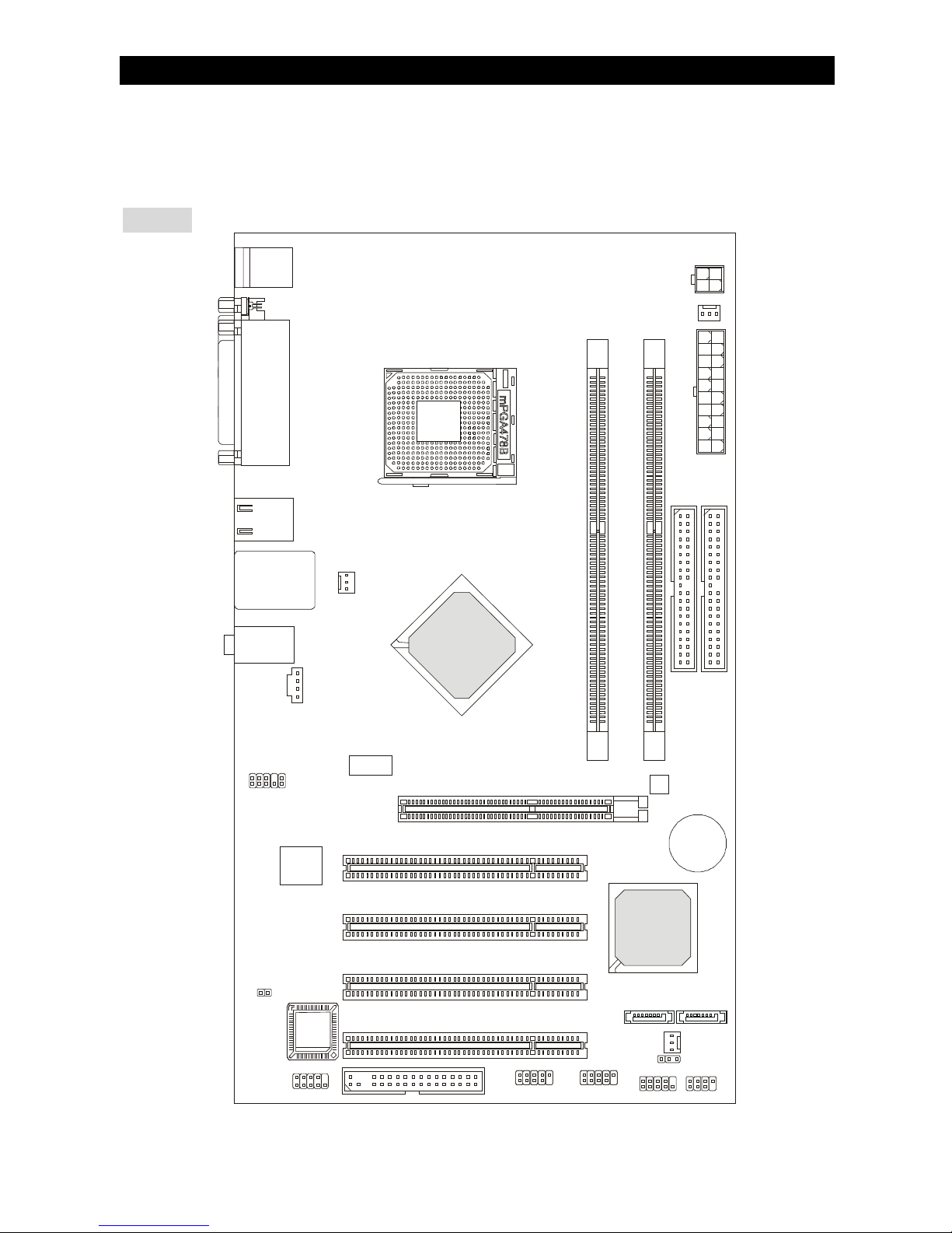
Thank you for choosing 865PE-V2 Series (MS-7156 v1.A) ATX mainboard. The 865PE-V2
Series is based on Intel® 865PE & Intel® ICH5 chipsets for optimal system efficiency. Designed to
fit the advanced Intel® P4 Prescott processors in 478 pin package, the 865PE-V2 Series delivers
a high performance and professional desktop platform solution.
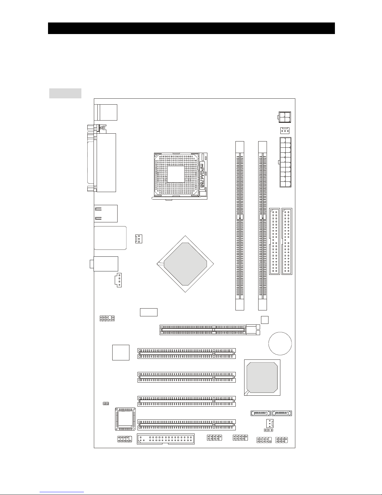
Layout
B
A
T
T
+
BIOS
JCOM1
JCI1
JAUD1
LAN
IDE2
SATA1
Intel ICH5
JUSB1 JUSB2
JFP1 JFP2
PCI4
FDD1
PCI3
PCI2
PCI1
SATA2
JBAT1
SYSFAN1
DIMM1
DIMM2
PWRFAN1
JPW1
IDE1
AUDI02000
CPUFAN1
T:
Line-Out
B:Mic
Line-In
M:
Top : mouse
Bottom: keyboard
USB
ports
Top: LAN Jack
Bottom: USB
ports
Intel 865PE
ATX1
AGP1
Top :
Parallel Port
Bottom:
Com Port
Page 8

2
Specifications
CPU
l Supports Intel® Pentium 4 Prescott processors in 478 pin package.
l FSB 400 / 533 / 800 MHz (FSB 400 for Northwood Celeron only).
l Supports up to 3.4GHz or higher speed.
(For the latest information about CPU, please visit
http://www.msi.com.tw/program/products/mainboard/mbd/pro_mbd_cpu_support.php)
Chipset
l Intel® 865PE chipset
- Supports FSB 800/533/400MHz.
- Supports AGP 8X interface.
- Supports DDR 400/333/266 memory interface.
l Intel® ICH5 chipset
- Hi-Speed USB (USB2.0) controller, 480Mb/sec, 8 ports.
- 2 Serial ATA/150 ports.
- 2 channel Ultra ATA 100 bus Master IDE controller.
- PCI Master V2.3, I/O APIC.
- Supports both ACPI and legacy APM power management.
Main Memory
l Supports two unbuffered DIMM of 2.5 Volt DDR SDRAM.
l Supports up to 2GB memory size without ECC.
l Supports Dual channel DDR266/333/400 MHz.
(For the updated supporting memory modules, please visit
http://www.msi.com.tw/program/products/mainboard/mbd/pro_mbd_trp_list.php)
Slots
l One AGP slot supports 8x/4x at 1.5V (3.3V is not supported).
l Four 32-bit v2.3 Master PCI bus slots (support 3.3v/5v PCI bus interface).
On-Board IDE
l Dual Ultra DMA 66/100 IDE controllers integrated in ICH5.
- Supports PIO, Bus Master operation modes.
- Can connect up to four Ultra ATA drives.
l Serial ATA/150 controller integrated in ICH5.
- Up to 150MB/sec transfer speeds.
- Can connect up to two Serial ATA drives.
On-Board Peripherals
l On-Board Peripherals include:
- 1 floppy port supports 1 FDD with 360K, 720K, 1.2M, 1.44M and 2.88Mbytes
- 1 serial port on the rear panel
- 1 serial port with pinheader (through external cable)
- 1 parallel port supports SPP/EPP/ECP mode
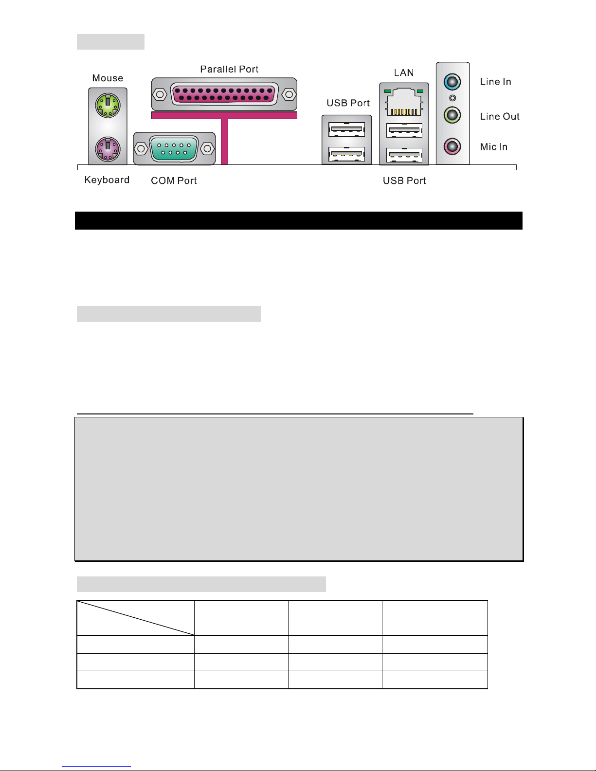
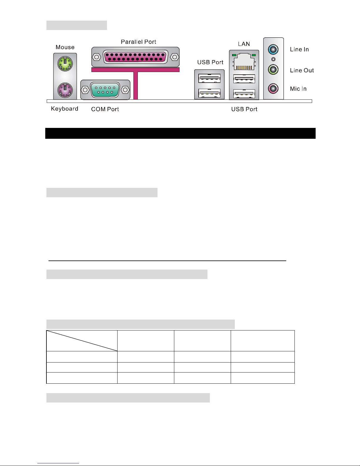
- 8 USB 2.0 ports (Rear * 4/ Front * 4)
- 1 Line-In / Line-Out / Mic-In
- 1 RJ45 LAN jack
Audio
l AC97 link controller integrated in Intel® 865PE chipset.
l 5.1-channel audio codec ADI AD1888.
- Compliance with AC97 v2.3 Spec.
- Meet PC2001 audio performance requirement.
Page 9
3
LAN
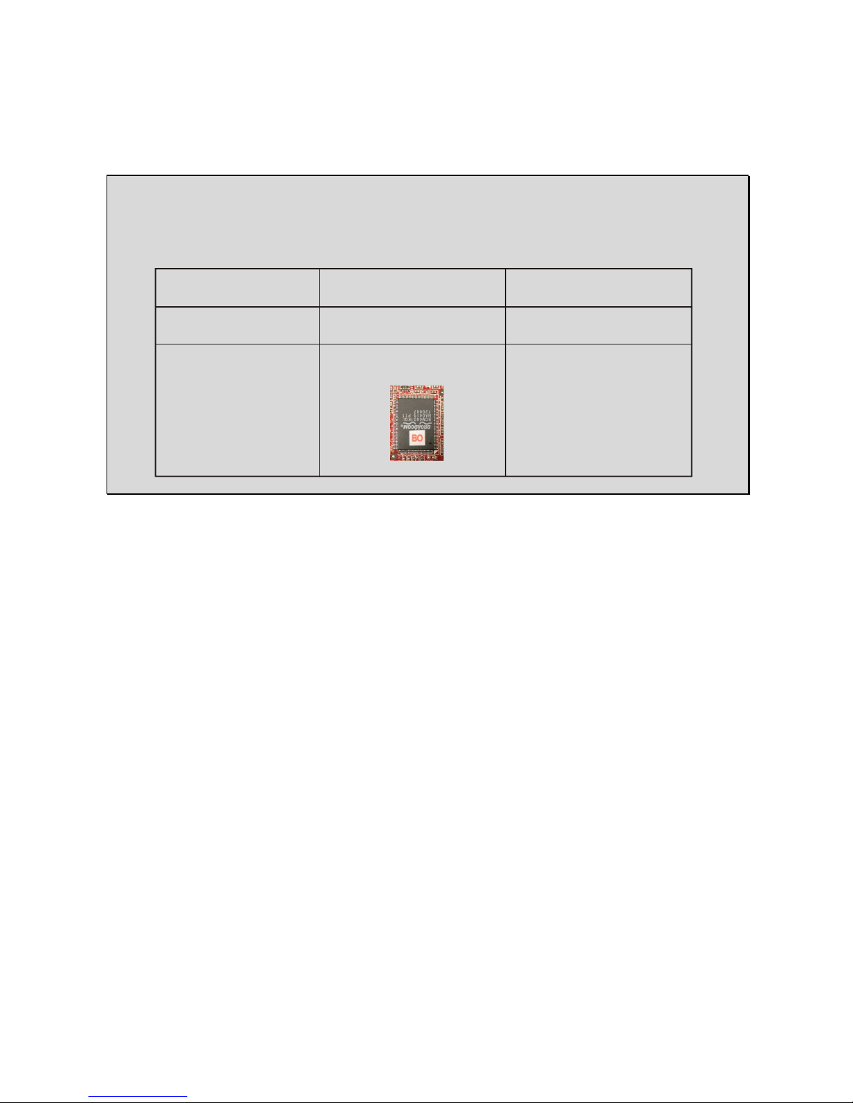
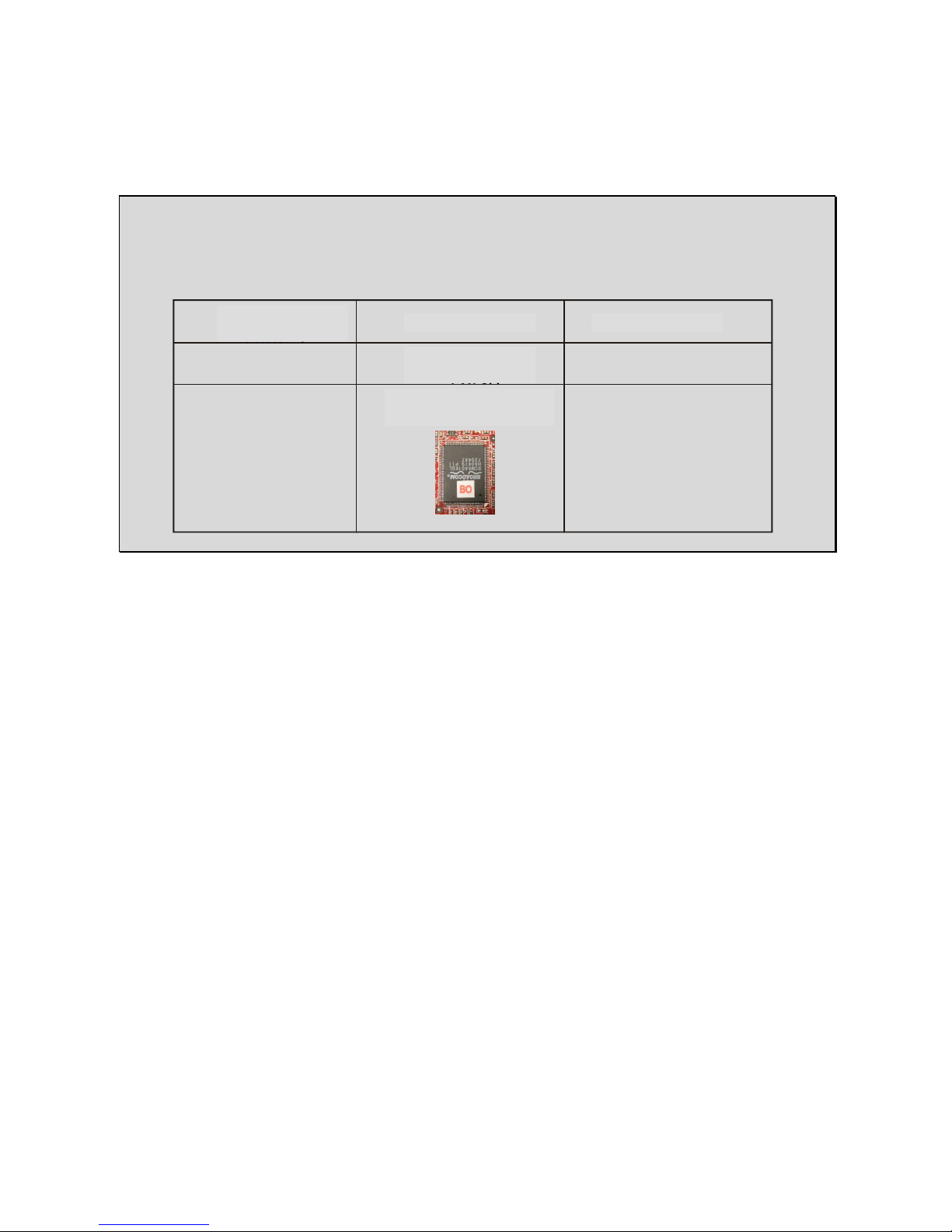
l Broadcom® 4401 ver. A1 / ver. B0 (optional)
- Integrated Fast Ethernet MAC and PHY in one chip.
- Supports 10Mb/s, 100Mb/s.
- Compliance with PCI 2.2.
- Supports ACPI Power Management.
MSI Reminds You...
Different Broadcom LAN version chips have different BIOS to support. If you want to manually
download the latest BIOS for updating, be sure to use the correct one. Please refer the form
below for details.
BIOS
l The mainboard BIOS provides “Plug & Play” BIOS which detects the peripheral devices
and expansion cards of the board automatically.
l The mainboard provides a Desktop Management Interface (DMI) function which records
your mainboard specifications.
Dimension
l ATX Form Factor: 30.5 cm (L) x 17.5 cm (W).
Mounting
l 6 mounting holes.
Broadcom 4401
LAN Version
A1
B0
Sticker
Non-sticker
on LAN Chip
3.X
1.X
Have a sticker [B0]
on LAN Chip
BIOS Version
Page 10
4
Rear Panel
The rear panel provides the following connectors:
Hardware Setup
This chapter tells you how to install the CPU, memory modules, and expansion cards, as well as
how to setup the jumpers on the mainboard. It also provides the instructions on connecting the
peripheral devices, such as the mouse, keyboard, etc. While doing the installation, be careful in
holding the components and follow the installation procedures.
Central Processing Unit: CPU
The mainboard supports Intel® Pentium 4 Prescott processor. The mainboard uses a CPU socket
called socket478. When you are installing the CPU, make sure to install the cooler to prevent
overheating. If you do not have the CPU cooler, contact your dealer to purchase and install them
before turning on the computer.
(For the latest information about CPU, please visit
http://www.msi.com.tw/program/products/mainboard/mbd/pro_mbd_cpu_support.php.)
MSI Reminds You...
Overheating
Overheating will seriously damage the CPU and the system, always make sure the cooling fan
can work properly to protect the CPU from overheating.
Overclocking
This mainboard is designed to support overclocking. However, please make sure your
components are able to tolerate such abnormal setting, while doing overclocking. Any attempt to
operate beyond product specifications is not recommended. We do not guarantee the damages
or risks caused by inadequate operation or beyond product specifications.
Memory Speed/CPU FSB Support Matrix
Memory
FSB
DDR 266 DDR 333 DDR 400
400 MHz OK N/A N/A
533 MHz OK OK N/A
800 MHz N/A OK OK
Page 11

5
CPU Installation Procedures for Socket 478
1. Please turn off the power and unplug the power cord before installing the CPU.
2. Pull the lever sideways away from the socket. Make sure to raise the lever up to a
90-degree angle.
3. Look for the gold arrow. The gold arrow should point towards the lever pivot. The CPU can
only fit in the correct orientation.
4. If the CPU is correctly installed, the pins should be completely embedded into the socket
and can not be seen. Please note that any violation of the correct installation procedures
may cause permanent damages to your mainboard.
5. Press the CPU down firmly into the socket and close the lever. As the CPU is likely to
move while the lever is being closed, always close the lever with your fingers pressing
tightly on top of the CPU to make sure the CPU is properly and completely embedded into
the socket.
Installing the CPU Fan
As processor technology pushes to faster speeds and higher performance, thermal management
becomes increasingly important. To dissipate heat, you need to attach the CPU cooling fan and
heatsink on top of the CPU. Follow the instructions below to install the Heatsink/Fan:
1. Locate the CPU and its retention mechanism on the motherboard.
2. Position the heatsink onto the retention mechanism.
3. Mount the fan on top of the heatsink. Press down the fan until its four clips get wedged in
the holes of the retention mechanism.
4. Press the two levers down to fasten the fan. Each lever can be pressed down in only ONE
direction.
5. Connect the fan power cable from the mounted fan to the 3-pin fan power connector on
the board.
MSI Reminds You...
Overheating…
Overheating will seriously damage the CPU and system, always make sure the cooling fan can
work properly to protect the CPU from overheating.
Replacing the CPU…
While replacing the CPU, always turn off the ATX power supply or unplug the power supply’s
power cord from grounded outlet first to ensure the safety of CPU.
Page 12

6
Memory
The mainboard provides two 184-pin unbuffered DDR 266 / DDR333 / DDR400 DDR SDRAM,
and supports the memory size up to 2GB. To operate properly, at least one DIMM module must
be installed. (For the updated supporting memory modules, please visit
http://www.msi.com.tw/program/products/mainboard/mbd/pro_mbd_trp_list.php)
Install at least one DIMM module on the slots. Memory modules can be installed on the slots in
any order. You can install either single- or double-sided modules to meet your own needs.
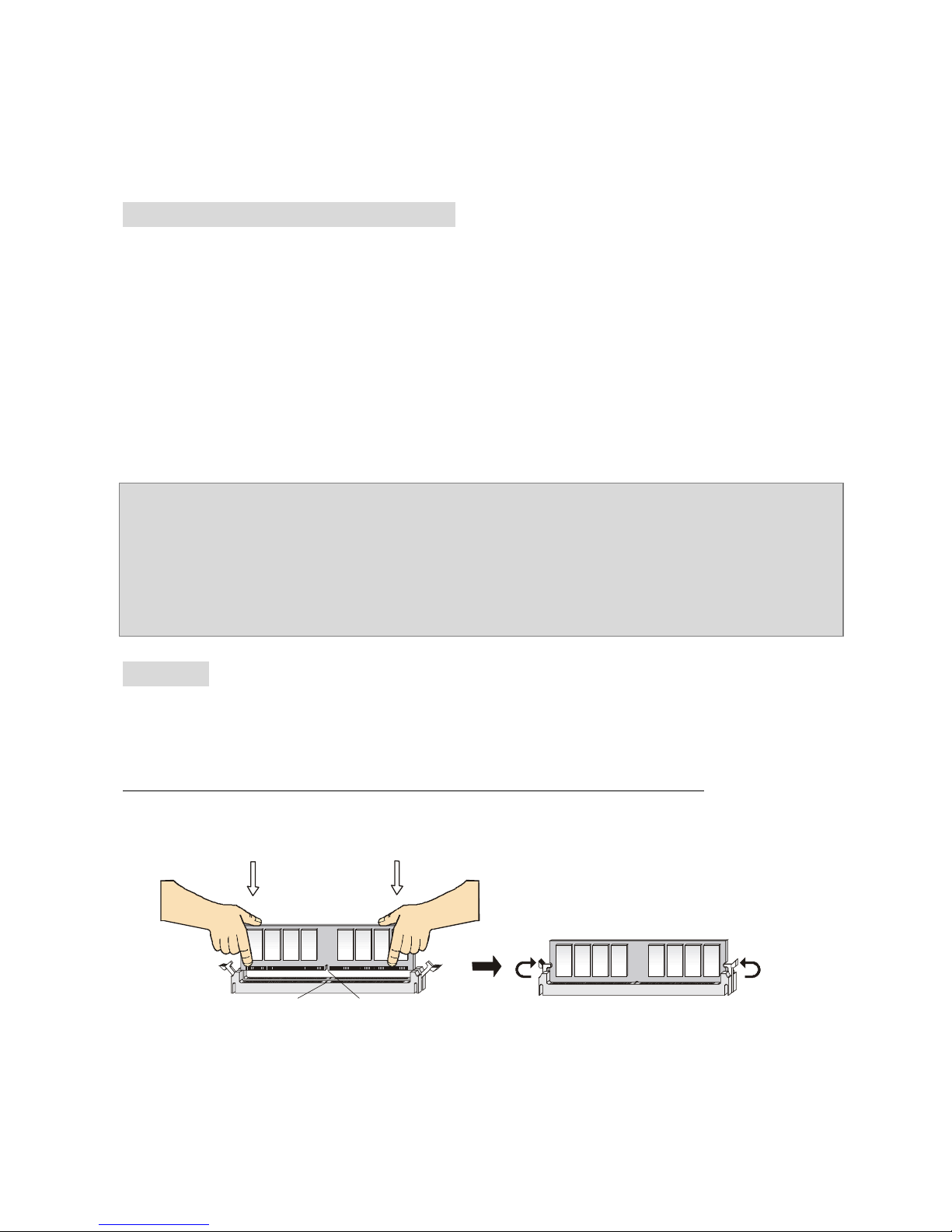
Installing DDR Modules
1. The DDR DIMM has only one notch on the center of module. The module will only fit in the
right orientation.
2. Insert the DIMM memory module vertically into the DIMM slot. Then push it in until the
golden finger on the memory module is deeply inserted in the socket.
3. The plastic clip at each side of the DIMM slot will automatically close.
Power Supply
The mainboard supports ATX power supply for the power system. Before inserting the power
supply connector, always make sure that all components are installed properly to ensure that no
damage will be caused. A 300W or above power supply is suggested.
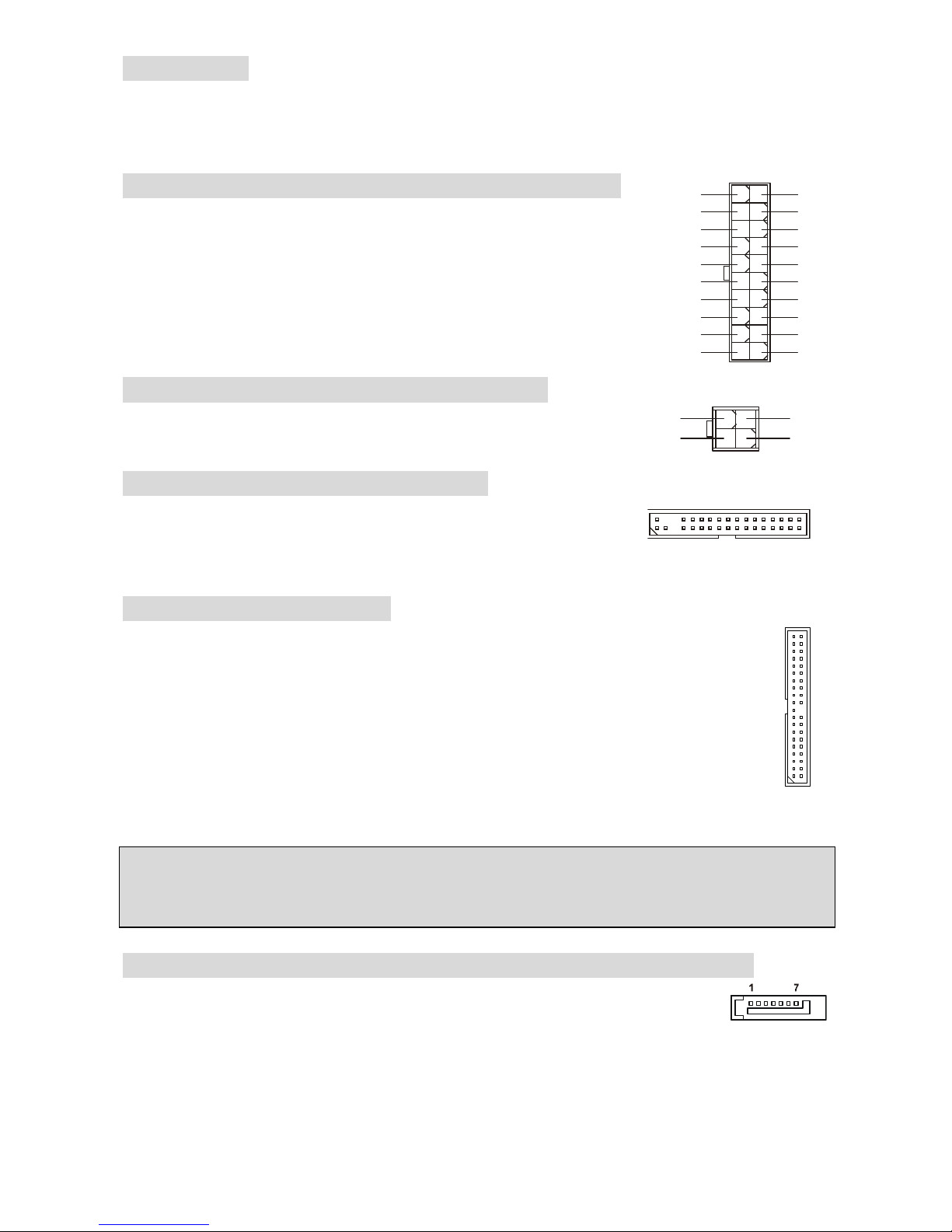
ATX 20-Pin Power Connector: ATX1
This connector allows you to connect an ATX 20-pin power
supply. To connect the ATX 20-pin power supply, make sure
the plug of the power supply is inserted in the proper
orientation and the pins are aligned. Then push down the
power supply firmly into the connector.
ATX 12V Power Connector: JPW1
This 12V power connector is used to provide power to the CPU.
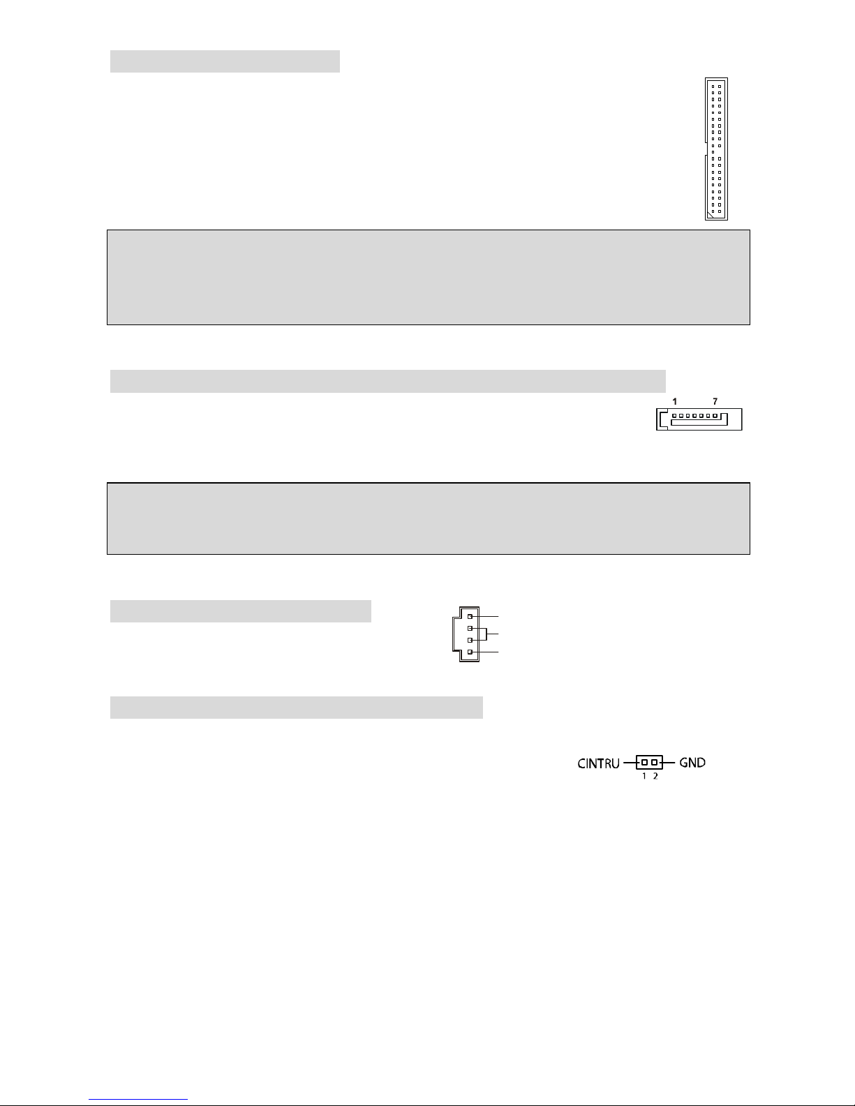
Floppy Disk Drive Connector: FDD1
The mainboard provides a standard floppy disk drive connector that
supports 360K, 720K, 1.2M, 1.44M and 2.88M floppy disk types.
Notch
Volt
11011
20
+3.3V
+3.3V
-12V
+3.3V
GND GND
PS-ON#
+5V
GND GND
GND +5V
GND GND
-5V
PWR OK
+5V 5VSB
+5V +12V
1
3
4
2
GND
12V
GND
12V
Page 13
7
IDE Connector: IDE1/IDE2
The mainboard has dual Ultra DMA 66/100 controller that provides PIO mode 0~4, Bus
Master, and Ultra DMA 66/100 function. You can connect up to four hard disk drives,
CD-ROM, 120MB Floppy and other devices.
The first hard drive should always be connected to IDE1. IDE1 can connect a Master
and a Slave drive. You must configure second hard drive to Slave mode by setting the
jumper accordingly.
MSI Reminds You...
If you install two hard disks on one cable, you must configure the second drive to Slave mode by
setting its jumper. Refer to the hard disk documentation supplied by hard disk vendors for jumper
setting instructions.
Serial ATA Connectors controlled by Intel® ICH5: SATA1/SATA2
The mainboard provides dual high-speed Serial ATA interface ports. The ports
supper 1st generation Serial ATA data rates of 150MB/s and are fully compliant
with Serial ATA 1.0 specifications. Each Serial ATA connector can connect to 1 hard disk device.
MSI Reminds You...
Please do not fold the serial ATA cable in a 90-degree angle, which will cause the loss of data
during transmission.
CD-In Connector: AUDIO2000
The connector is for CD-ROM audio connector.
Chassis Intrusion Switch Connector: JCI1
This connector is connected to a 2-pin chassis switch. JCI1 is
compliant with Intel® Front Panel I/O Connectivity Design Guide.
L
R
GND
Page 14
8
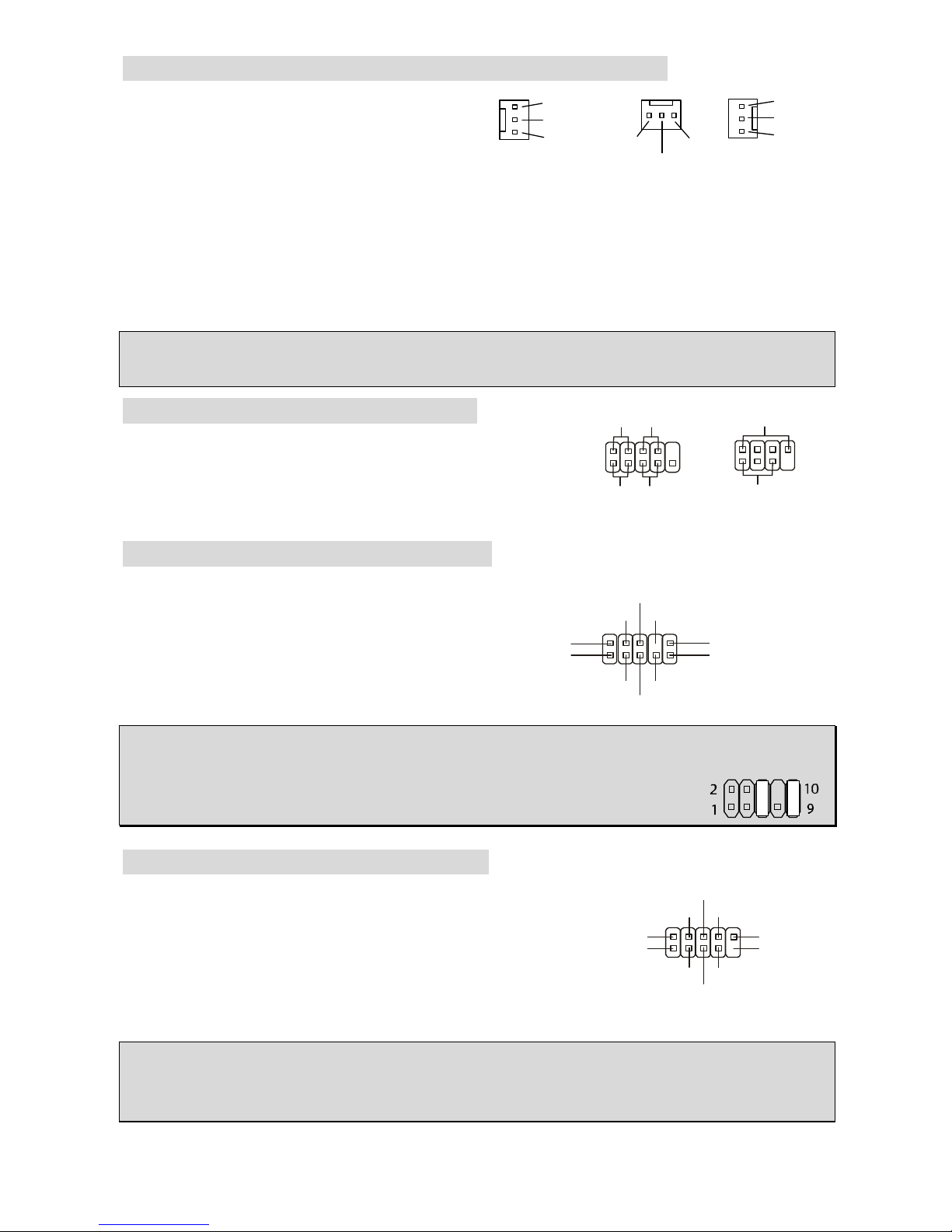
Fan Power Connectors: CPUFAN1/PWRFAN1/SYSFAN1
The 3-pin CPUFAN1 (processor fan) and 3-pin
PWRFAN1 (power supply fan) / SYSFAN1
(system fan) support system cooling fan with
+12V. CPUFAN1 can support three- or four-pin
head connector.
When connecting the wire to the connectors, always take note that the red wire is the positive
and should be connected to the +12V, the black wire is Ground and should be connected to GND.
If the mainboard has a System Hardware Monitor chipset on-board, you must use a specially
designed fan with speed sensor to take advantage of the CPU fan control.
MSI Reminds You...
Always consult the vendors for the proper CPU cooling fan.
Front Panel Connectors: JFP1/JFP2
The mainboard provides two front panel connectors for
electrical connection to the front panel switches and LEDs.
JFP1 is compliant with Intel® Front Panel I/O Connectivity
Design Guide.
Front Panel Audio Connector: JAUD1
The front panel audio connector allows you to
connect to the front panel audio and is
compliant with Intel® Front Panel I/O
Connectivity Design Guide.
MSI Reminds You...
If you do not want to connect to the front audio header, pins 5 & 6, 9 & 10 have
to be jumpered in order to have signal output directed to the rear audio ports.
Otherwise, the Line-Out connector on the back panel will not function.
Front USB Connector: JUSB1/JUSB2
The mainboard provides two standard USB 2.0 pin headers
JUSB1&JUSB2. USB2.0 technology increases data transfer
rate up to a maximum throughput of 480Mbps, which is 40
times faster than USB 1.1, and is ideal for connecting
high-speed USB interface peripherals such as USB HDD,
digital cameras, MP3 players, printers, modems, etc.
MSI Reminds You...
Please note that the pins of VCC & GND must be connected correctly or it may cause some
damage
GND
+12V
Sensor
+12V
Sensor
+12V
GND
GND
Sensor
CPUFAN1 SYSFAN1PWRFAN1
JFP1
Power
LED
HDD
LED
Reset
Switch
Power
Switch
1 9
2
10
JFP2
Power
LED
Speaker
1
728
(2)AUD_GND
AUD_VCC
AUD_RET_R
Key
AUD_RET_L(10)
(1)AUD_MIC
AUD_MIC_BIAS
AUD_FPOUT_R
HP_ON
AUD_FPOUT_L(9)
(2)VCC
USB1- GND
GND
USB0-
USB0+
USB1+
USB0C(10)
(1)VCC Key(9)
Page 15
9
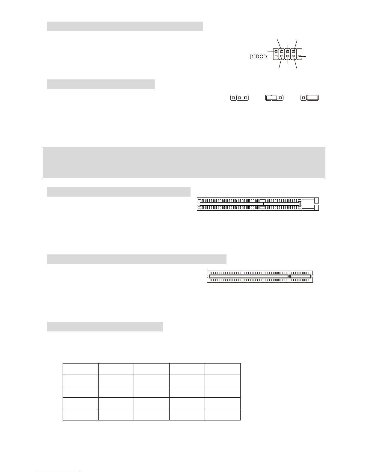
Serial Port Connector: JCOM1 (Optional)
The mainboard offers one 9-pin male DIN connector COM 1 (on the
rear panel), and one optional serial port JCOM1. Both are 16550A
high speed communication ports that send/receive 16 bytes FIFOs.
You can attach a serial mouse or other serial device directly to them.
Clear CMOS Jumper: JBAT1
There is a CMOS RAM on board that has a power supply from
external battery to keep the data of system configuration. With
the CMOS RAM, the system can automatically boot OS every
time it is turned on. If you want to clear the system configuration, use the JBAT1 (Clear CMOS
Jumper) to clear data. Follow the instructions in the image to clear the data.
MSI Reminds You...
You can clear CMOS by shorting 2-3 pin while the system is off. Then return to 1-2 pin position.
Avoid clearing the CMOS while the system is on, which will damage the mainboard.
AGP (Accelerated Graphics Port) Slot
The AGP slot allows you to insert the AGP
graphics card. AGP is an interface specification
designed for the throughput demands of 3D graphics. It introduces a 66MHz, 32-bit channel for
the graphics controller to directly access main memory. The slot supports AGP card for 8x/4x at
1.5v (3.3v is not supported).
PCI (Peripheral Component Interconnect) Slots
The PCI slots allow you to insert the expansion cards
to meet your needs. When adding or removing
expansion cards, make sure that you unplug the power supply first. Meanwhile, read the
documentation for the expansion card to make any necessary hardware or software settings for
the expansion card, such as jumpers, switches or BIOS configuration.
PCI Interrupt Request Routing
The IRQ, abbreviation of interrupt request line and pronounced I-R-Q, are hardware lines over
which devices can send interrupt signals to the microprocessor. The PCI IRQ pins are typically
connected to the PCI bus INT A# ~ INT D# pins as follows:
Order1 Order2 Order3 Order4
PCI Slot 1 INT B# INT C# INT D# INT A#
PCI Slot 2 INT C# INT D# INT A# INT B#
PCI Slot 3 INT D# INT A# INT B# INT C#
PCI Slot 4 INT A# INT B# INT C# INT D#
333111222
Keep Data
Clear Data
GND
DSR
RTS
CTS
RI[9]
SOUT
[2]SIN
DTR
Page 16
10
BIOS Setup
Power on the computer and the system will start POST (Power On Self Test) process. When the
message below appears on the screen, press <DEL> key to enter Setup.
DEL: Setup
If the message disappears before you respond and you still wish to enter Setup, restart the
system by turning it OFF and On or pressing the RESET button. You may also restart the system
by simultaneously pressing <Ctrl>, <Alt>, and <Delete> keys.
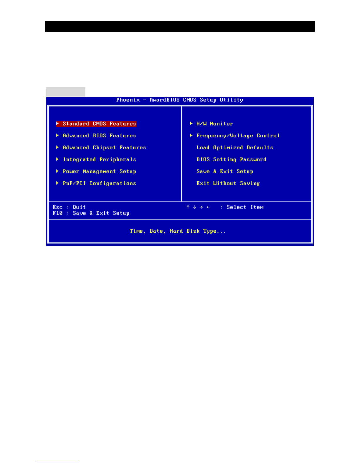
Main Page
Standard CMOS Features
Use this menu for basic system configurations, such as time, date etc.
Advanced BIOS Features
Use this menu to setup the items of Award special enhanced features.
Advanced Chipset Features
Use this menu to change the values in the chipset registers and optimize your system
performance.
Integrated Peripherals
Use this menu to specify your settings for integrated peripherals.
Power Management Setup
Use this menu to specify your settings for power management.
PnP/PCI Configurations
This entry appears if your system supports PnP/PCI.
H/W Monitor
This entry shows the status of your CPU, fan, warning for overall system status.
Frequency/Voltage Control
Use this menu to specify your settings for frequency/voltage control.
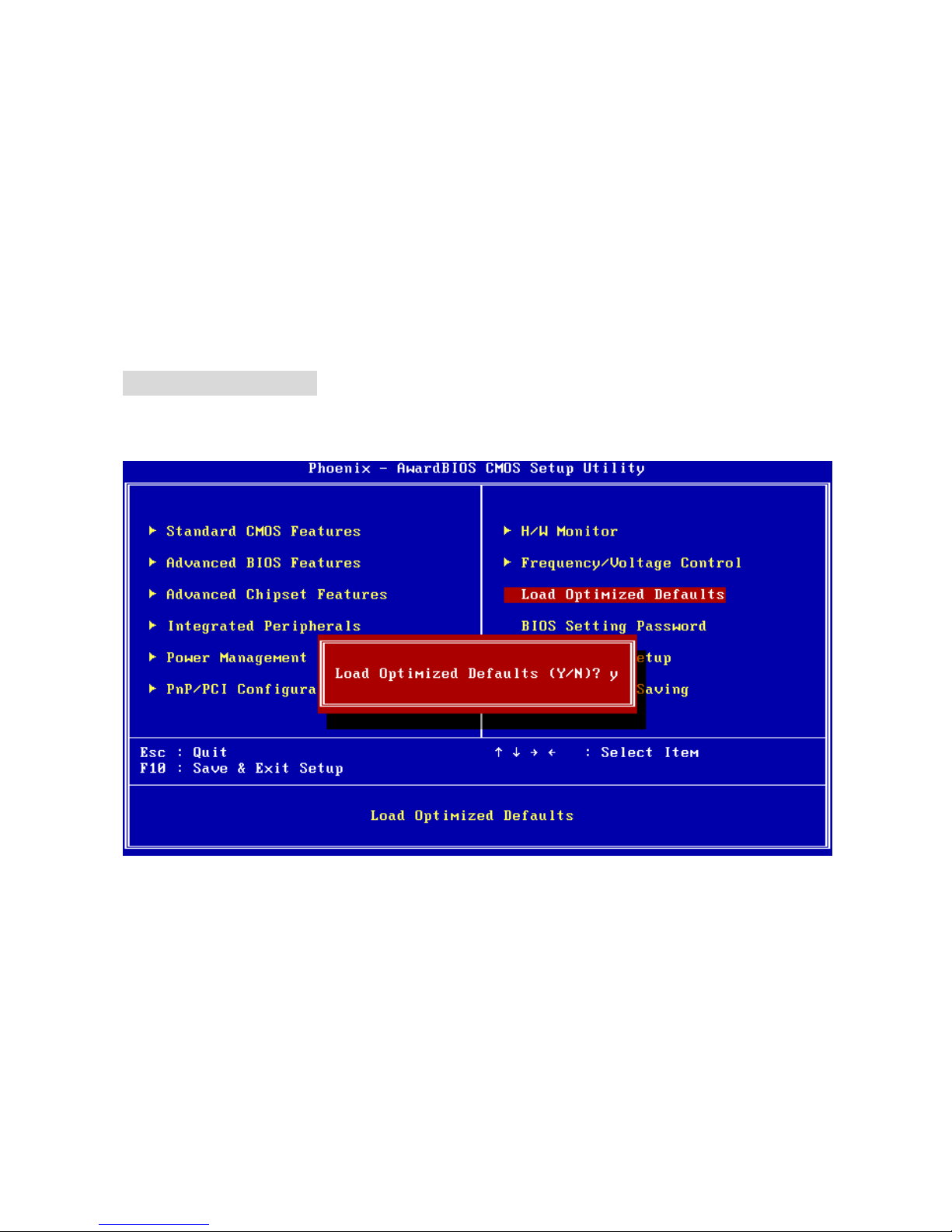
Load Optimized Defaults
Use this menu to load the default values set by the mainboard manufacturer specifically for
optimal performance of the mainboard.
BIOS Setting Password
Use this menu to set password.
Page 17

11
Save & Exit Setup
Save changes to CMOS and exit setup.
Exit Without Saving
Abandon all changes and exit setup.
Frequency/Voltage Control
Current CPU Clock
It shows the current clock of CPU. Read-only.
CPU Clock Ratio
This item allows you to adjust the CPU ratio. It might be locked by CPU hardware and this item
will be hided.
DDR Power Voltage
Adjusting the DDR voltage can increase the DDR speed. Any changes made to this setting may
cause a stability issue, so changing the DDR voltage for long-term purpose is NOT
recommended.
AGP Power Voltage
AGP voltage is adjustable in the field, allowing you to increase the performance of your AGP
display card when overclocking, but the stability may be affected. Setting options: 1.5V to 1.8V at
0.05V increment.
Auto Detect PCI Clk
This item is used to auto detect the PCI slots. When set to [Enabled], the system will remove
(turn off) clocks from empty PCI slots to minimize the electromagnetic interference (EMI).
Settings: [Enabled], [Disabled].
Page 18
12
Spread Spectrum
When the motherboard’s clock generator pulses, the extreme values (spikes) of the pulses
creates EMI (Electromagnetic Interference). The Spread Spectrum function reduces the EMI
generated by modulating the pulses so that the spikes of the pulses are reduced to flatter curves.
If you do not have any EMI problem, leave the setting at [Disabled] for optimal system stability
and performance. But if you are plagued by EMI, select the desired range for EMI reduction.
Remember to disable Spread Spectrum function if you are overclocking, because even a slight
jitter can introduce a temporary boost in clock speed which may just cause your overclocked
processor to lock up.
CPU Clock
This item allows you to select the CPU Front Side Bus clock frequency (in MHz) and overclock
the processor by adjusting the FSB clock to a higher frequency.
Load BIOS Defaults
You can load the default values provided by the mainboard manufacturer for the stable
performance.
Page 19
13
Introduction
Félicitations, vous venez d’acquérir une carte mère ATX 865PE-V2 Series (MS-7156 v1.A) La
865PE-V2 Series est basée sur les Chipsets Intel® 865PE & Intel® ICH5 offrant un système très
performant. La carte fonctionne avec les processeurs Intel® P4 Prescott 400/533/800MHz
(Socket 478), est très performante et offre une solution adaptée tant aux professionnels qu’aux
particuliers.
Schéma
B
A
T
T
+
BIOS
JCOM1
JCI1
JAUD1
LAN
IDE2
SATA1
Intel ICH5
JUSB1 JUSB2
JFP1 JFP2
PCI4
FDD1
PCI3
PCI2
PCI1
SATA2
JBAT1
SYSFAN1
DIMM1
DIMM2
PWRFAN1
JPW1
IDE1
AUDI02000
CPUFAN1
T:
Line-Out
B:Mic
Line-In
M:
Top : mouse
Bottom: keyboard
USB
ports
Top: LAN Jack
Bottom: USB
ports
Intel 865PE
ATX1
AGP1
Top :
Parallel Port
Bottom:
Com Port
Page 20

14
Spécificités
CPU
l Supporte les processeurs Intel® P4 Northwood/Prescott (Socket 478) jusqu’à 3.4 GHz
(Pour les dernières mises à jours concernant les CPU, vous pouvez visiter :
http://www.msi.com.tw/program/products/mainboard/mbd/pro_mbd_cpu_support.php.)
Chipset
l Chipset Intel® 865PE
- Supporte FSB 800/533/400MHz.
- Supporte l’interface AGP 8X.
- Supporte l’interface de mémoire DDR 400/333/266.
l Chipset Intel® ICH5
- contrôleur Hi-Speed USB (USB2.0), 480Mb/sec, 8 ports.
- 2 ports Serial ATA/150.
- 2 contrôleurs IDE bus Master channel Ultra ATA 100.
- PCI Master V2.3, I/O APIC.
- Supporte à la fois l’ACPI et la gestion de l’alimentation (APM).
Mémoire Principale
l Supporte deux DIMM unbuffered de2.5 Volt DDR SDRAM.
l Supporte jusqu’à 2GB de mémoire non ECC.
l Supporte le double canal DDR266/333/400 MHz.
(Pour nue mise à jour sur les modules de mémoires supportés, veuillez visiter
http://www.msi.com.tw/program/products/mainboard/mbd/pro_mbd_trp_list.php )
Slots
l Un slot AGP supportant 8x/4x à 1.5V (le 3.3V n’est pas supporté).
l Quatre slots PCI bus Master 32-bit v2.3 (supporte l’ interface bus PCI 3.3v/5v).
IDE Intégré
l Deux contrôleurs IDE Ultra DMA 66/100 intégrés dans ICH5.
- Supporte les modes opératoires PIO, Bus Master.
- Possibilité de connecter jusqu’à quatre disques Ultra ATA.
l Contrôleur Serial ATA/150 intégré dans ICH5.
- Vitesse de transfert jusqu’à 150MB/sec.
- Peut connecter jusqu’à deux disques Serial ATA.
Périphériques Intégrés
l Périphériques Intégrés Inclus:
- 1 port floppy supportant 1 FDD avec 360K, 720K, 1.2M, 1.44M et 2.88Mbytes
- 1 port série sur le panneau arrière
- 1 port série sur broches à travers un câble externe
- 1 port parallèle supportant les modes SPP/EPP/ECP
- 8 ports USB 2.0 (Arrière * 4/ Avant * 4)
- 1 Line-In / Line-Out / Mic-In
- 1 RJ45 LAN jack
Audio
l Contrôleur AC97 link integré dans le chipset Intel® 865PE.
l 5.1 canaux audio codec ADI AD1888.
- Compatible avec les Spec AC97 v2.3.
- Répond aux exigences audio PC2001.
Page 21
15
LAN
l Broadcom® 4401
- Fast Ethernet MAC et PHY Integré dans une puce.
- Supporte 10Mb/s, 100Mb/s.
- Compatible avec PCI 2.2.
- Supporte l’ACPI Power Management.
MSI vous rappel…
Différentes versions du chip LAN Broadcom sont supportés par des BIOS différents. Si vous
téléchargez manuellement une mise à jour de BIOS, assurez vous de télécharger à celui qui
correspond à votre carte. Référez vous au tableau suivant.
BIOS
l La carte procure un BIOS “Plug & Play” qui détecte automatiquement les cartes
d’extension ou les périphériques.
l La carte offre une interface DMI (Desktop Management Interface) qui enregistre les
spécificités de la carte mère.
Dimension
l Format ATX : 30.5 cm (L) x 17.5 cm (W).
Montage
l 6 trous de montage.
Broadcom 4401
LAN Version
A1
B0
Sticker
Non-sticker
on LAN Chip
3.X
1.X
Have a sticker [B0]
on LAN Chip
BIOS Version
Version de Chip
Broadcom 4401
Autocollant Version du BIOS
Aucun Autocollant
sur le Chip
Autocollant [B0]
Sur le Chip
Page 22
16
Panneau Arrière
Le panneau arrière procure les connecteurs suivants:
Installation Matériel
Ce chapitre vous indique comment installer le CPU, la mémoire ainsi que les cartes d’extension
ou encore le réglage des cavaliers présents sur la carte. Vous aurez aussi des instructions
relatives à la connexion des périphériques tels que la souris, le clavier etc. Lors de l’installation
veuillez faire très attention aux éléments composant la carte mère et suivez bien les procédure
d’installations.
Central Processing Unit: CPU
La carte mère supporte les processeurs Intel Pentium 4/Celeron(D) (socket 478). La carte mère
utilise un socket appelé PGA478 permettant une installation aisée du processeur. Lors de
l’installation du CPU, assurez-vous que le CPU possède bien un système de refroidissement
constitué d’un dissipateur + ventilateur permettant la dissipation de la chaleur. Pour connaître le
modèle de ventilateur nécessaire à la bonne utilisation de votre système n’hésitez pas à
contacter votre revendeur. (Pour connaître les dernières informations concernant le CPU,
veuillez visiter
(http://www.msi.com.tw/program/products/mainboard/mbd/pro_mbd_cpu_support.php)
Exemple de Dérivation du CPU Core Speed
Si Horloge CPU = 133MHz
Ration Core/Bus = 23
Alors Vitesse CPU = Horloge x ratio Core/Bus
= 133MHz x 23
= 3.06 GHz
Tableau de support de vitesse mémoire / CPU FSB
Memory
FSB
DDR 266 DDR 333 DDR 400
400 MHz OK N/A N/A
533 MHz OK OK N/A
800 MHz N/A OK OK
Procédure d’Installation du CPU Socket 478
1. Veuillez éteindre ou débrancher le PC avant d’installer le CPU.
2. Tirer le levier qui se trouve sur le côté du socket. Assurez-vous que celui-ci est bien relevé
(position 90°).
3. Chercher la marque dorée sur le CPU. La marque dorée doit pointer vers le pivot du levier.
Page 23
17
Le CPU peut ne s’installer que dans une seule position.
4. Si le CPU est correctement installé, les pattes doivent être complètement insérées dans le
socket et ne plus être visibles. Veuillez noter qu’une mauvaise installation endommage à
coup sur le processeur ainsi que la carte mère.
5. Appuyer sur le CPU et baisser le levier. Ainsi le CPU ne peut plus bouger et reste fixe sur
le socket.
Installation du Ventilateur de CPU
La technologie faisant augmenter rapidement la vitesse des nouveaux CPU, il devient donc
nécessaire de prêter attention à la dissipation thermique (refroidissement du CPU). C’est la
raison pour laquelle vous devez installer un système de refroidissement en phase avec votre
processeur. Suivez les instructions ci dessous afin d’installer votre système de refroidissement :
1. Localiser le CPU et son système de rétention sur la carte mère.
2. Positionner le dissipateur au dessus du mécanisme de rétention du CPU.
3. Monter le ventilateur sur le dissipateur. Appuyer sur l’ensemble jusqu’à ce que vous
puissiez attacher le ventilateur au mécanisme de rétention.
4. Appuyer sur les deux leviers du ventilateur. Chaque levier ne peut se manipuler que dans
un seul sens.
5. Connecter le câble d’alimentation sur le connecteur de la carte mère prévu à cet effet (3
broches).
MSI Vous Rappelle...
Surchauffe
La surchauffe endommagera le CPU ainsi que le système, c’est pourquoi il faut un ventilateur
adéquat afin de protéger votre PC.
Remplacer le CPU
Lorsque vous remplacez les CPU, veuillez toujours couper le courant ou débrancher la prise
pour éviter tout problème et ne pas endommager votre PC.
Mémoire
La carte mère possède deux slots (184 broches) pour modules de mémoire DDR 266 / DDR333 /
DDR400 DDR SDRAM, et supporte un maximum de mémoire jusqu’à 2GB. Pour fonctionner
correctement, il faut au moins installer un module de mémoire DIMM. (Pour les dernières mises
à jours de mémoire supportées, merci de visiter
http://www.msi.com.tw/program/products/mainboard/mbd/pro_mbd_trp_list.php )
Installer au moins un module DIMM sur les slots. L’installation des modules de mémoires n’a pas
de sens particulier. Vous pouvez installer soit des modules simples ou doubles faces selon vos
besoins.
1. Le DDR DIMM ne possède qu’une encoche en son centre. Ainsi il n’est possible de
monter le module que dans un seul sens.
2. Insérez le module de mémoire DIMM verticalement dans le slot. Puis
appuyez dessus
3. Le clip en plastique situé de chaque côté du module va se fermer
automatiquement.
Notch
Volt
Page 24
18
Alimentation
La carte mère supporte les alimentations ATX. Avant de brancher le connecteur d’alimentation,
Il faut toujours vous assurer que tous les composants sont bien installés afin de ne pas les
endommager. Une alimentation 300W ou supérieur est préconisée.
Connecteur d’Alimentation ATX 20 Broches : ATX1
Ce connecteur vous permet de connecter l’alimentation ATX. Pour ce
faire assurez-vous que le connecteur est bien positionné dans le bon
sens. Puis appuyer sur le câble.
Connecteur d’alimentation ATX 12V : JPW1
Le connecteur d’alimentation 12V est utilisé pour alimenter le CPU
Connecteur Floppy Disk Drive: FDD1
La carte offre un connecteur standard floppy disk drive (lecteur de
disquette) qui supporte les disques 360K, 720K, 1.2M, 1.44M et
2.88M
Connecteur IDE: IDE1/IDE2
La carte mère possède un contrôleur 32-bit Enhanced PCI IDE et Ultra DMA
66/100/133 qui procure les fonctions PIO mode 0~4, Bus Master, et Ultra DMA
33/66/100/133. Vous pouvez connecter jusqu’à 4 matériels (disques durs, CD-ROM,
120MB Floppy).
Le premier disque dur doit être connecté sur l’IDE1. L’IDE1 peut recevoir un matériel
Maître et un Esclave. Vous devez configurer le second disque en mode Esclave et ce à
l’aide du cavalier situé à l’arrière.
MSI Vous Rappelle...
Si vous voulez installer deux disques durs, vous devez configurer le second en Esclave en
configurant le cavalier. Se référer à la documentation du disque dur pour les instructions.
Connecteurs Serial ATA contrôlés par Intel® ICH5: SATA1/SATA2
La carte mère procure deux ports d’interface haute vitesse Serial ATA. Elle
supporte la 1e génération de serial ATA (taux de transfert 150 MB/s).
Ces quatre connecteurs sont entièrement compatibles avec le Serial ATA 1.0. Chaque
connecteur peut être connecté à un disque dur..
Le Southbridge de cette carte est Intel ICH6, qui supporte quatre connecteurs de série SATA1 ~
SATA4. SATA1 ~ SATA4 sont deux ports d’interface dual high-speed Serial ATA. Chacun
11011
20
+3.3V
+3.3V
-12V
+3.3V
GND GND
PS-ON#
+5V
GND GND
GND +5V
GND GND
-5V
PWR OK
+5V 5VSB
+5V +12V
1
3
4
2
GND
12V
GND
12V
Page 25

19
MSI Vous Rappelle...
Ne pas tordre le câble à 90° afin de ne pas l’endommager et éviter les pertes de données lors du
transfert.
Connecteur CD-In: AUDIO2000
Le connecteur est destiné au branchement audio du CD-ROM
Connecteur Chassis Intrusion Switch: JCI1
Ce connecteur est connecté à deux broches chassis switch. JCI1
est compatible avec l’Intel® Front Panel I/O Connectivity Design
Guide.
Connecteurs d’alimentation de ventilateur:
CPUFAN1/PWRFAN1/SYSFAN1
Le CPUFAN1 (Ventilateur de processeur) et le
PWRFAN1 (ventilateur d’alimentation) /
SYSFAN1 (ventilateur de système) supporte le
+12V. CPUFAN1 peut supporter 3 ou 4 broches.
Lors de la connexion du câble, assurez-vous
que le fil rouge soit connecté au +12V et le fil noir connecté au “GND“. Si la carte mère possède
un système de gestion intégré, vous devez utiliser un ventilateur ayant ces caractéristiques si
vous voulez contrôler le ventilateur du CPU
MSI Vous rappelle...
Il faut toujours consulter votre revendeur au sujet du ventilateur
Connecteurs Front Panel: JFP1/JFP2
La carte mère procure 2 connecteurs pour les branchements
électriques (LED disque dur…). JFP1 est compatible avec le
Design Intel Front Panel I/O Connectivity Design Guide
Connecteur Front Panel Audio: JAUD1
Le connecteur audio JAUD1 vous permet de
connecter l’audio en façade et est compatible
avec lntel ® Front Panel I/O Connectivity
Design Guide
MSI Vous rappelle...
Si vous ne voulez pas connecter l’audio en façade à l’aide des broches 5 & 6,
9 & 10 doivent être recouvertes par un cavalier pour envoyer le signal vers les
ports audio à l’arrière. Autrement le connecteur Line-Out à l’arrière ne fonctionnera pas.
L
R
GND
GND
+12V
Sensor
+12V
Sensor
+12V
GND
GND
Sensor
CPUFAN1 SYSFAN1PWRFAN1
JFP1
Power
LED
HDD
LED
Reset
Switch
Power
Switch
1 9
2
10
JFP2
Power
LED
Speaker
1
728
(2)AUD_GND
AUD_VCC
AUD_RET_R
Key
AUD_RET_L(10)
(1)AUD_MIC
AUD_MIC_BIAS
AUD_FPOUT_R
HP_ON
AUD_FPOUT_L(9)
Page 26

20
Connecteur Front USB: JUSB1/JUSB2
La carte mère procure deux connecteurs standard 2.0
JUSB1&JUSB2. La technologie USB 2.0 accroît le taux de
transfert jusqu’à 480Mbps, ce qui est 40 fois plus rapide que
l’ USB 1.1. Idéal pour connecter des périphériques
gourmand en bande passante (appareil photo numérique,
caméra numérique etc).
MSI Vous Rappelle...
A noter que les broches VCC et GND doivent être correctement connecter afin d’éviter tout
endommagement.
Connecteur Port de série: JCOM1 (Optionnel)
a carte mère offre un connecteur COM1 9-pin male DIN (sur le
panneau arrière), et un port de série optionnel JCOM1. Tous deux
sont des ports de communication haute vitesse 16550A qui
envoie/reçoit 16 bytes FIFOs. Vous pouvez y attaché une souris de
série ou autre composants de série directement.
Cavalier Clear CMOS : JBAT1
La CMOS RAM intégré reçoit une alimentation d’une batterie
externe qui permet de garder les données de configuration du
système. Avec la CMOS RAM, le système peut
automatiquement booter avec les paramètres personnalisés du BIOS à chaque fois que le PC
est allumé. Si vous voulez effacer la configuration du système, utilisez le JBAT1 (Cavalier Clear
CMOS) pour effacer les données. Suivez les instructions de l’image pour effacer les données.
MSI Vous Rappelle...
Vous pouvez effacer les données en positionnant le cavalier sur les broches 2-3 quand le PC
n’est pas allumé. Puis il faut remettre le cavalier en position 1-2. Ne surtout pas effacer les
données (Position 2-3) lorsque le PC est en fonction, cela endommagera la carte mère.
Slot AGP (Accelerated Graphics Port)
Le slot AGR vous permet de connecter une carte
graphique AGP. Cette interface est
particulièrement bien adaptée aux applications 3D. Contrôleur 66MHz, 32-bit avec accès direct à
la mémoire principale. Le slot supporte les cartes AGP 8x/4x à 1.5v (3.3v n’est pas supporté).
(2)VCC
USB1- GND
GND
USB0-
USB0+
USB1+
USB0C(10)
(1)VCC Key(9)
333111222
Keep Data
Clear Data
GND
DSR
RTS
CTS
RI[9]
SOUT
[2]SIN
DTR
Page 27

21
Slots PCI (Peripheral Component Interconnect)
Les slots PCI vous permettent la connexion de cartes
d’extension selon vos besoins. Pour installer ou retirer
une carte PCI, il faut que le PC soit éteint. Si la carte PCI nécessite des réglages, veuillez vous
reporter à la documentation fournie avec cette dernière.
PCI Interrupt Request Routing
IRQ est l’abréviation de “interrupt request line”. Les IRQ sont des signaux émis par des matériels.
Les PCI IRQ sont connectés généralement au broches PCI bus INT A# ~ INT D# comme
suivant:
Order1 Order2 Order3 Order4
PCI Slot 1 INT B# INT C# INT D# INT A#
PCI Slot 2 INT C# INT D# INT A# INT B#
PCI Slot 3 INT D# INT A# INT B# INT C#
PCI Slot 4 INT A# INT B# INT C# INT D#
Page 28

22
Setup du BIOS
Lorsque le PC démarre le processus de POST (Power On Self Test) se met en route. Quand le
message ci-dessous apparaît, appuyer sur <DEL> pour accéder au Setup.
DEL: Setup
Si le message disparaît avant que n’ayez appuyé sur la touche, redémarrez le PC à l’aide du
bouton RESET. Vous pouvez aussi redémarrer en utilisant la combinaison de touches <Ctrl>,
<Alt>, et <Delete>.
Page Principale
Standard CMOS Features
Cette fonction permet le paramétrage des éléments standard du BIOS.
Advanced BIOS Features
Cette fonction permet de paramétrer des éléments avancés du Bios.
Advanced Chipset Features
Cette option vous permet de paramétrer les éléments relatifs au registre du chipset, permettant
ainsi d’optimiser les performances de votre système.
Integrated Peripherals
Utiliser ce menu pour paramétrer les périphériques intégrés.
Power Management Setup
Utilisez ce menu pour appliquer vos choix en ce qui concerne le power management.
PNP/PCI Configurations
Apparaît si votre système supporte PNP/PCI.
H/W Monitor
Utiliser ce menu pour visualiser les informations du système
Frequency/Voltage Control
Utiliser ce menu pour configurer vos paramètres de pour le contrôle de la fréquence et du
voltage.
Page 29

23
Load Optimized Defaults
Utiliser ce menu pour charger les paramètres par défaut du BIOS.
BIOS Setting Password
Utiliser ce menu pour entrer un mot de passe
Save & Exit Setup
Sauvegarder les changements du CMOS et sortir de l’utilitaire de Setup.
Exit Without Saving
Abandonner tous les changements et sortir de l’utilitaire de Setup
Frequency/Voltage Control
Current CPU Clock
Montre la fréquence d’horloge du CPU. (à lire uniquement)
CPU Clock Ratio
Cet élément permet de modifier le ratio CPU.
DDR Power Voltage
En ajustant le voltage DDR, vous pouvez augmenter la vitesse DDR. Tout changement effectué
sur cette option peut entraîner une instabilité, donc changer le voltage DDR à long terme n’est
pas recommandé.
AGP Power Voltage
Le voltage AGP est ajustable dans ce champs, vous permettant d’augmenter les performances
de l’affichage de votre carte AGP quand vous overclockez, mais la stabilité peut être affectée.
Page 30

24
Auto Detect PCI Clk
Cet élément est utilisé pour détecter automatiquement les slots PCI. En position [Enabled], le
système ne veut plus alimenter les slots PCI libres pour réduire les émissions
éléctromagnétiques (EMI). Paramètres: [Enabled], [Disabled].
Spread Spectrum
Les cartes mères créent des EMI (Electromagnetic Interference). La fonction de Spread
Spectrum réduit ces EMI. Si vous n’avez pas de problème d’EMI, laisser l’option sur Disabled,
ceci vous permet une stabilité du système et des performances optimales. Dans le cas contraire,
choisissez Enabled pour réduire les EMI. N’oubliez pas de désactiver cette fonction si vous
voulez faire de l’overclocking, afin d’éviter tout problème. Les options : [Disabled], [Enabled].
CPU Clock
Cet élément vous permet de sélectionner la fréquence d’horloge du CPU Front Side Bus (en
MHz), et c’est une possibilité d’overclocker le FDB en indiquant une fréquence supérieure.
Load BIOS Defaults
Vous pouvez charger les paramètres par défaut procurés par le constructeur de la carte mère
pour une performance stable.
Page 31

25
Einleitung
Danke, dass Sie das 865PE-V2 Series (MS-7156 v1.A) ATX Mainboard gewählt haben. Das
865PE-V2 Series basiert auf den Intel® 865PE und Intel® ICH5 Chipsätzen und ermöglicht so ein
optimales und effizientes System. Entworfen, um die fortschrittlichen Intel® Pentium® 4
/Celeron(D) Prozessoren mit 478 Pins aufzunehmen, stellt das 865PE-V2 Series die ideale
Lösung zum Aufbau eines professionellen Hochleistungsdesktopsystems dar.
Layout
B
A
T
T
+
BIOS
JCOM1
JCI1
JAUD1
LAN
IDE2
SATA1
Intel ICH5
JUSB1 JUSB2
JFP1 JFP2
PCI4
FDD1
PCI3
PCI2
PCI1
SATA2
JBAT1
SYSFAN1
DIMM1 DIMM2
PWRFAN1
JPW1
IDE1
AUDI02000
CPUFAN1
T:
Line-Out
B:Mic
Line-In
M:
Top : mouse
Bottom: keyboard
USB
ports
Top: LAN Jack
Bottom: USB
ports
Intel 865PE
ATX1
AGP1
Top :
Parallel Port
Bottom:
Com Port
Page 32

26
Spezifikationen
CPU
l Unterstützt Intel ® Pentium 4/Celeron (D) (Sockel 478) Prozessoren mit bis zu 3.4GHz.
(Um die neuesten Informationen zu unterstützten Prozessoren zu erhalten, besuchen Sie bitte
http://www.msi.com.tw/program/products/mainboard/mbd/pro_mbd_cpu_support.php )
Chipsatz
l Intel® 865PE Chipsatz
- Unterstützt FSB 800/533/400MHz.
- Unterstützt AGP 8X Schnittstelle.
- Unterstützt DDR 400/333/266 Speicherschnittstelle.
l Intel® ICH5 Chipsatz
- Hochgeschwindigkeits- USB (USB2.0) Kontroller, 480Mb/Sek., 8 Anschlüsse.
- 2 Serial ATA/150 Ports.
- 2 Kanal Ultra ATA 100 Bus Master IDE Kontroller.
- PCI Master V2.3, I/O APIC.
- Unterstützt ACPI und ist abwärtskompatibel zur APM Stromsparfunktionalität.
Hauptspeicher
l Unterstützt zwei ungepufferte 2.5 Volt DDR SDRAM DIMMs.
l Unterstützt den Speicherausbau auf bis zu 2GB ohne ECC.
l Unterstützt Dual Channel DDR266/333/400 MHz.
(Um den letzten Stand bezüglich der unterstützten Speichermodule zu erhalten, besuchen Sie
bitte http://www.msi.com.tw/program/products/mainboard/mbd/pro_mbd_trp_list.php )
Slots
l Eine 1,5V AGP 8-fach/4-fach Schnittstelle (3,3V nicht unterstützt).
l Vier PCI V2.3 32-Bit PCI Bus Sockel (3,3V/5V PCI Bus unterstützt).
On-Board IDE
l In den ICH5 integrierte Dual Ultra DMA 66/100 IDE Kontroller.
- Unterstützt die Betriebsmodi PIO und Bus Mastering.
- Bis zu vier Ultra ATA Geräte anschließbar.
l In den ICH5 integrierter Serial ATA/150 Kontroller.
- Übertragungsgeschwindigkeit bis zu 150MB/Sek.
- Bis zu zwei Serial ATA Laufwerke anschließbar.
Peripherieanschlüsse onboard
l hierzu gehören:
- 1 Anschluss für ein Diskettenlaufwerke mit 360 KB, 720 KB, 1,2 MB, 1,44 MB oder
2,88 MB
- 1 Serielle Schnittstelle am hinteren Anschlusspaneel
- 1 Serielle Schnittstelle ausgeführt als Stiftleiste (Externer Anschluss über Kabel)
- 1 Parallele Schnittstelle, die die Betriebsmodi SPP/EPP/ECP unterstützt
- 8 USB 2.0 Anschlüsse (4 hintere/ 4 vordere)
- 1 Satz Audioanschlüsse (Eingang/ Ausgang/ Mikrofon).
- 1 RJ45 LAN Buchse.
Audio
l In den Intel® 865PE Chipsatz integrierter AC97 Anschlusskontroller.
l 5.1-Kanal ADI AD1888 Audio Codec.
- Erfüllt die Anforderungen der Spezifikationen gemäß AC97 V2.3
- Genügt den Audio- Leistungsanforderungen nach PC2001.
Page 33

27
LAN
l Broadcom® 4401
- Integrierter Fast Ethernet MAC und PHY in einem Chip.
- Unterstützt Betrieb mit 10Mb/s oder 100Mb/s.
- Erfüllt die Anforderungen gemäß dem Standard PCI V2.2
- Unterstützt ACPI Stromsparfunktionalität.
MSI weist darauf hin...
Die Broadcom LAN Bausteine können sich in der Version und unterstütztem BIOS
unterscheiden. Bevor Sie das neuste BIOS runterladen, achten Sie auf die korrekte Version.
Bitte achten Sie dabei auf folgende Details:
BIOS
l Das Mainboard- BIOS verfügt über “Plug & Play”- Funktionalität, mit der angeschlossene
Peripheriegeräte und Erweiterungskarten automatisch erkannt werden.
l Das Mainboard stellt ein Desktop - Management - Interface (DMI) zur Verfügung, welches
automatisch die Spezifikationen Ihres Mainboards aufzeichnet.
Abmessungen
l ATX Form Faktor: 30,5 cm (L) x 17,5 cm (B).
Montage
l 6 Montagebohrungen.
Broadcom 4401
LAN Version
A1
B0
Sticker
Non-sticker
on LAN Chip
3.X
1.X
Have a sticker [B0]
on LAN Chip
BIOS Version
Broadcom 4401
LAN Version
Aufkleber BIOS Version
Kein Aufkleber auf dem
LAN Chip
Aufkleber [B0]
auf dem LAN Chip
Page 34

28
Hinteres Anschlusspaneel
Das hintere Paneel verfügt über folgende Anschlüsse:
Hardware Setup
Dieses Kapitel informiert Sie darüber, wie Sie die CPU, Speichermodule und Erweiterungskarten
einbauen, des weiteren darüber, wie die Steckbrücken auf dem Mainboard gesetzt werden.
Zudem bietet es Hinweise darauf, wie Sie Peripheriegeräte anschließen, wie z.B. Maus, Tastatur,
usw. Handhaben Sie die Komponenten während des Einbaus vorsichtig und halten Sie sich an
die vorgegebene Vorgehensweise beim Einbau.
Hauptprozessor: CPU
Das Mainboard unterstützt Intel Pentium 4 / Celeron(D) Prozessoren mit 478 Pins. Hierbei setzt
das Mainboard den CPU Sockel PGA478 ein, um den CPU- Einbau zu erleichtern. Achten Sie
beim Einbau bitte darauf, dass die CPU immer mit einem Kühlkörper mit aktivem Prozessorlüfter
versehen sein muss, um Überhitzung zu vermeiden. Verfügen Sie über keinen Kühlkörper mit
aktivem Prozessorlüfter, setzen Sie sich bitte mit Ihrem Händler in Verbindung, um einen solchen
zu erwerben und danach zu installieren, bevor Sie Ihren Computer anschalten.
(Um die neuesten Informationen zu unterstützten Prozessoren zu erhalten, besuchen Sie bitte
http://www.msi.com.tw/program/products/mainboard/mbd/pro_mbd_cpu_support.php)
Beispiel zur Ermittlung des Kerntaktes
Wenn externer CPU-Takt = 133 MHz
Kern-/Systemtaktmultiplikator = 23
dann ist Kerntakt = externer CPU-Takt x Kern/Sytemtaktmultiplikator
= 133 MHz x 23
= 3,06 GHz
Tabelle Speichergeschwindigkeit/ unterstützter CPU FSB
Memory
FSB
DDR 266 DDR 333 DDR 400
400 MHz OK N/A N/A
533 MHz OK OK N/A
800 MHz N/A OK OK
Page 35

29
Vorgehensweise beim CPU-Einbau beim Sockel 478
1. Bitte schalten Sie das System aus und ziehen Sie den Netzstecker, bevor Sie die CPU
einbauen.
2. Ziehen Sie den Hebel leicht seitlich weg vom Sockel, heben Sie ihn danach bis zu einem
Winkel von 90° an.
3. Machen Sie den goldenen Pfeil ausfindig, er sollte auf das Hebelgelenk zeigen. Die CPU
passt nur in der korrekten Ausrichtung.
4. Ist die CPU korrekt installiert, sollten die Pins an der Unterseite vollständig versenkt und
nicht mehr sichtbar sein. Beachten Sie bitte, dass jede Abweichung von der richtigen
Vorgehensweise beim Einbau Ihr Mainboard dauerhaft beschädigen kann.
5. Drücken Sie die CPU fest in den Sockel und drücken Sie den Hebel wieder nach unten bis
in seine Ursprungsstellung. Da die CPU während des Schließens des Hebels dazu neigt,
sich zu bewegen, sichern Sie diese bitte während des Vorgangs durch permanenten
Fingerdruck von oben, um sicherzustellen, dass die CPU richtig und vollständig im Sockel
sitzt.
Installation des CPU Kühlers
Mit dem Fortschritt der Prozessortechnologie, der zu immer höheren Geschwindigkeiten und
Leistungen führt, wird Temperaturkontrolle immer wichtiger. Um die Hitze abzuleiten, müssen Sie
einen CPU-Kühler mit Lüfter auf der CPU installieren. Befolgen Sie zur Installation des Kühlers
die folgenden Anweisungen:
1. Machen Sie die CPU und ihren Rückhaltemechanismus auf dem Motherboard ausfindig.
2. Platzieren Sie den Kühlkörper auf dem Rückhaltemechanismus.
3. Setzen Sie den Lüfter auf den Kühlkörper. Pressen Sie den Lüfter nach unten, bis seine
vier Klammern in den Löchern des Rückhaltemechanismus einrasten. Drücken Sie die
zwei Hebel herab, um den Lüfter zu befestigen. Jeder Hebel kann nur in EINER Richtung
herabgedrückt werden.
4. Verbinden Sie das Stromkabel des montierten Lüfters mit dem 3-poligen
Stromanschluss auf dem Board.
MSI weist darauf hin...
Überhitzung …
Überhitzung beschädigt die CPU und das System nachhaltig, stellen Sie stets eine korrekte
Funktionsweise des CPU Kühlers sicher, um die CPU vor Überhitzung zu sch ützen.
Auswechseln der CPU …
Stellen Sie während eines CPU-Wechsels immer sicher, dass das ATX Netzteil ausgeschaltet ist
und ziehen Sie zuerst den Netzstecker, um die Unversehrtheit Ihrer CPU zu gewährleisten.
Speicher
Das Mainboard bietet Platz für zwei ungepufferte 184-Pin DDR 266 / DDR333 / DDR400 DDR
SDRAMs und unterstützt den Speicherausbau auf bis zu 2GB. Um einen ordnungsgemäßen
Betrieb zu ermöglichen, muss mindestens ein DIMM- Speichermodul eingesetzt sein. (Um den
letzten Stand bezüglich der unterst ützten Speichermodule zu erhalten, besuchen Sie bitte
http://www.msi.com.tw/program/products/mainboard/mbd/pro_mbd_trp_list.php)
Setzen Sie mindestens ein Speichermodul in einen Stecksockel. Die Speichermodule können in
Page 36

30
beliebiger Reihenfolge eingesetzt werden. Gemäß Ihren Anforderungen können Sie sowohl einals auch doppelseitige Module verwenden
1. DDR DIMMs haben nur eine Kerbe in der Mitte des Moduls. Sie passen nur in
einer Richtung in den Sockel.
2. Setzen Sie den DIMM- Speicherbaustein senkrecht in den DIMM- Sockel, dann
drücken Sie ihn hinein, bis die goldenen Kontakte tief im Sockel sitzen.
3. Die Plastikklammern an den Seiten des DIMM- Sockels schließen sich
automatisch
Stromversorgung
Das Mainboard unterstützt zur Stromversorgung ATX Netzteile. Bevor Sie den Netzteilstecker
einstecken, stellen Sie stets sicher, dass alle Komponenten ordnungsgemäß eingebaut sind, um
Schäden auszuschließen. Es wird ein Netzteil mit 300W oder mehr empfohlen.
ATX 20-Pin Stromanschluss: ATX1
Hier können Sie ein ATX Netzteil anschließen. Wenn Sie die
Verbindung herstellen, stellen Sie sicher, dass der Stecker in der
korrekten Ausrichtung eingesteckt wird und die Pins ausgerichtet
sind. Drücken Sie dann den Netzteilstecker fest in den
Steckersockel.
ATX 12V Stromanschluss: JPW1
Dieser 12V Stromanschluss wird verwendet, um die CPU mit Strom
zu versorgen.
Anschluss des Diskettenlaufwerks: FDD1
Das Mainboard verfügt über einen Standardanschluss für
Diskettenlaufwerke mit 360 KB, 720 KB, 1,2 MB, 1,44 MB oder 2,88
MB Kapazität.
IDE Festplattenanschluss: IDE1/IDE2
Das Mainboard besitzt einen Dual Ultra DMA 66/100 Kontroller, der die PIO Modi 0- 4
bereitstellt, Bus Mastering beherrscht und Ultra DMA 66/100 Funktionalität bietet. Es
können bis zu vier Festplatten, CD-ROM-, 120MB Disketten-Laufwerke und andere
Geräte angeschlossen werden. Die erste Festplatte sollte immer an IDE1
angeschlossen werden. IDE1 kann ein Master- und ein Slave- Laufwerk verwalten. Das
zweite Laufwerk muss durch das entsprechende Setzen einer Steckbrücke als Slave
eingestellt werden.
Kerbe
Volt
11011
20
+3.3V
+3.3V
-12V
+3.3V
GND GND
PS-ON#
+5V
GND GND
GND +5V
GND GND
-5V
PWR OK
+5V 5VSB
+5V +12V
1
3
4
2
GND
12V
GND
12V
Page 37

31
MSI weist darauf hin...
Verbinden Sie zwei Laufwerke über ein Kabel, müssen Sie das zweite Laufwerk im Slave-Modus
konfigurieren, indem Sie entsprechend den Jumper setzen. Entnehmen Sie bitte die Anweisungen zum Setzen des Jumpers der Dokumentation der Festplatte, die der Festplattenhersteller
zur Verfügung stellt.
Serial ATA Anschlüsse gesteuert durch den Intel® ICH5: SATA1/SATA2
Das Mainboard stellt Zweikanal- Serial ATA Hochgeschwindigkeitsschnittstellen
zur Verfügung. Jede unterstützt Serial ATA der 1sten Generation mit einem
Datendurchsatz von 150 MB/s. Jeder der Anschlüsse erfüllt vollständig die Serial ATA 1.0
Spezifikationen. An jedem Serial ATA Anschluss kann eine Festplatte angeschlossen werden.
MSI weist darauf hin...
Bitte falten Sie das Serial ATA Kabel nicht in einem Winkel von 90 Grad, da dies zu
Datenverlusten während der Datenübertragung führt.
CD-Eingang: AUDIO2000
Hier kann das Audiokabel des CD-ROM
Laufwerkes angeschlossen werden.
Gehäusekontaktschalter: JCI1
Hier wird ein 2-poliger Gehäusekontakschalter angeschlossen. JCI1
erfüllt die Anforderungen des „Intel® Front Panel I/O Connectivity
Design Guide.”
Stromanschlüsse für Lüfter: CPUFAN1/PWRFAN1/SYSFAN1
Der Anschluss CPUFAN1 (Prozessorlüfter) und
die dreipoligen Anschlüsse PWRFAN1
(Netzteillüfter) / SYSFAN1 (Systemlüfter)
unterstützen aktive Systemlüfter mit + 12V.
CPUFAN1 kann drei- und vierpolige Stecker
unterstützen.
Wenn Sie den Stecker mit dem Anschluss verbinden, sollten Sie immer darauf achten, dass der
rote Draht der positive Pol ist und mit +12V verbunden werden sollte, der schwarze Draht ist der
Erdkontakt und sollte mit GND verbunden werden. Ist Ihr Mainboard mit einem Chipsatz zur
Überwachung der Systemhardware und Steuerung der Lüfter versehen, dann brauchen Sie
einen speziellen Lüfter mit Tacho, um diese Funktion zu nutzen.
MSI weist darauf hin...
Bitten Sie stets Ihren Händler bei der Auswahl des geeigneten CPU Kühlers um Hilfe.
L
R
GND
GND
+12V
Sensor
+12V
Sensor
+12V
GND
GND
Sensor
CPUFAN1 SYSFAN1PWRFAN1
Page 38

32
Frontpaneel Anschlüsse: JFP1/JFP2
Das Mainboard verfügt über zwei Anschlüsse für das
Frontpaneel, diese dienen zum Anschluss der Schalter und
LEDs des Frontpaneels. JFP1 erfüllt die Anforderungen des
“ Intel® Front Panel I/O Connectivity Design Guide“.
Audioanschluss des Frontpaneels: JAUD1
Der Audio Vorderanschluss ermöglicht den
Anschluss von Audioein- und -ausgängen eines
Frontpaneels. Der Anschluss entspricht den
Richtlinien des “ Intel® Front Panel I/O
Connectivity Design Guide”.
MSI weist darauf hin...
Wenn Sie die vorderen Audioanschlüsse nicht verwenden, müssen die
Pins 5 & 6 und 9 & 10 mit sog. „Jumpern“ gebrückt werden, um die Signal-
ausgabe auf die hinteren Audioanschlüsse umzuleiten. Andernfalls ist der
Line -Out Ausgang im hinteren Anschlussfeld ohne Funktion.
USB Vorderanschluss: JUSB1/JUSB2
Das Mainboard verfügt über zwei Standard- USB- 2.0Anschlüsse in Form der Stift- Blöcke USB2 und USB3. Die
USB 2.0 Technologie erhöht den Datendurchsatz auf maximal
480Mbps, 40 mal schneller als USB 1.1 und ist bestens
geeignet, Hochgeschwindigkeits- USB- Peripheriegeräte
anzuschließen, wie z.B. USB Festplattenlaufwerke, Digitalkameras, MP3-Player, Drucker,
Modems und ähnliches.
MSI weist darauf hin...
Bitte beachten Sie, dass Sie die mit VCC (Stromführende Leitung) und GND (Erdleitung)
bezeichneten Pins korrekt verbinden müssen, ansonsten kann es zu Schäden kommen.
Serieller Anschluss: JCOM1 (Optional)
Das Mainboard bietet einen 9-Pin DIN Stecker COM 1 (am hinteren
Paneel) und optional zusätzlichen den Seriellen Anschluss JCOM1.
Es handelt sich bei beiden um 16550A
Hochgeschwindigkeitskommunikationsschnittstellen, die 16 Bytes
FIFOs senden/empfangen. An diese können Sie direkt eine Serielle Maus oder ein anderes
Serielles Gerät anschließen.
Steckbrücke zur CMOS-Löschung JBAT1
Auf dem Mainboard gibt es einen sogenannten CMOS
Speicher (RAM), der über eine Batterie gespeist wird und die
Daten der System- konfiguration enthält. Er ermöglicht es
dem Betriebssystem, mit jedem Einschalten automatisch hochzufahren. Wollen Sie die
Systemkonfiguration löschen, verwenden Sie hierfür JBAT1 (Clear CMOS Jumper - Steckbrücke
zur CMOS Löschung). Halten Sie sich an die folgenden Anweisungen, um die Daten löschen:
JFP1
Power
LED
HDD
LED
Reset
Switch
Power
Switch
1 9
2
10
JFP2
Power
LED
Speaker
1
728
(2)AUD_GND
AUD_VCC
AUD_RET_R
Key
AUD_RET_L(10)
(1)AUD_MIC
AUD_MIC_BIAS
AUD_FPOUT_R
HP_ON
AUD_FPOUT_L(9)
(2)VCC
USB1- GND
GND
USB0-
USB0+
USB1+
USB0C(10)
(1)VCC Key(9)
333111222
Keep Data
Clear Data
GND
DSR
RTS
CTS
RI[9]
SOUT
[2]SIN
DTR
Page 39

33
MSI weist darauf hin...
Sie können den CMOS löschen, indem Sie die Pins 2-3 verbinden, während das System
ausgeschaltet ist. Kehren Sie danach zur Pinposition 1-2 zurück. Löschen Sie den CMOS nicht,
solange das System angeschaltet ist, dies würde das Mainboard beschädigen.
AGP (Accelerated Graphics Port) Slot
Der AGP Slot ermöglicht den Einsatz einer AGP
Grafikkarte. AGP ist eine Schnittstellenspezifikation, die gemäß den Anforderungen von 3D Grafiken an den Datendurchsatz entwickelt
wurde. Mit ihr hat die direkte Anbindung des Grafikkontrollers an den Hauptspeicher über einen
mit 66MHz getakteten 32-Bit Kanal Einzug gehalten. Das Mainboard unterstützt AGP 8x/4x
Karten mit 1,5V (3,3V Karten nicht unterstützt).
PCI (Peripheral Component Interconnect) Slots
Die PCI Steckplätze ermöglichen Ihnen den Einsatz
von PCI- Karten, um das System Ihren
Anforderungen anzupassen. Stellen Sie vor dem Einsetzen oder Entnehmen von Karten sicher,
dass Sie den Netzstecker gezogen haben. Studieren Sie bitte die Anleitung zur
Erweiterungskarte, um jede notwendige Hard - oder Softwareeinstellung für die
Erweiterungskarte vorzunehmen, sei es an Steckbrücken (“Jumpern”), Schaltern oder im BIOS.
PCI Interrupt Request Routing
Die IRQs (Interrupt Request Lines) sind Hardwareverbindungen, über die Geräte
Interruptsignale an den Prozessor senden können. Die PCI IRQ Pins sind typischer Weise in der
folgenden Art mit den PCI Bus Pins INT A# ~ INT D# verbunden:
Reihenfolge 1 Reihenfolge 2 Reihenfolge 3 Reihenfolge 4
PCI Slot 1 INT B# INT C# INT D# INT A#
PCI Slot 2 INT C# INT D# INT A# INT B#
PCI Slot 3 INT D# INT A# INT B# INT C#
PCI Slot 4 INT A# INT B# INT C# INT D#
Page 40

34
BIOS Setup
Nach dem Einschalten beginnt der Computer den POST (Power On Self Test Selbstüberprüfung nach Anschalten). Sobald die Meldung unten erscheint, drücken Sie die Taste
<Entf>(<Del>), um das Setup aufzurufen.
DEL: Setup
Wenn die Nachricht verschwindet, bevor Sie reagieren und Sie möchten immer noch ins Setup,
starten Sie das System neu, indem Sie es erst AUS- und danach wieder ANSCHALTEN, oder die
“RESET”-Taste am Gehäuse betätigen. Sie können das System außerdem neu starten, indem
Sie gleichzeitig die Tasten <Strg>,<Alt> und <Entf> drücken (bei manchen Tastaturen
<Ctrl>,<Alt> und <Del>).
Hauptmenü
Standard CMOS Features
In diesem Menü können Sie die Basiskonfiguration Ihres Systems anpassen, so z.B. Uhrzeit,
Datum usw.
Advanced BIOS Features
Verwenden Sie diesen Menüpunkt, um Award -eigne weitergehende Einstellungen an Ihrem
System vorzunehmen.
Advanced Chipset Features
Verwenden Sie dieses Menü, um die Werte in den Chipsatzregistern zu ändern und die
Leistungsfähigkeit Ihres Systems zu optimieren.
Integrated Peripherals
Verwenden Sie dieses Menü, um die Einstellungen für in das Board integrierte Peripheriegeräte
vorzunehmen.
Power Management Setup
Verwenden Sie dieses Menü, um die Einstellungen für die Stromsparfunktionen vorzunehmen.
PNP/PCI Configurations
Dieser Eintrag erscheint, wenn Ihr System Plug and Play- Geräte am PCI-Bus unterstützt.
Page 41

35
H/W Monitor
Dieser Eintrag gibt den „Gesundheitszustand“ Ihres PCs wieder.
Frequency/Voltage Control
Hier können Sie Einstellungen zu Taktfrequenz und Spannung vornehmen.
Load Optimized Defaults
In diesem Menü können Sie Werkseinstellungen für das BIOS laden, die der Hersteller für den
Systembetrieb vorgibt.
BIOS Setting Password
Verwenden Sie dieses Menü, um das Kennwort einzugeben.
Save & Exit Setup
Abspeichern der BIOS-Änderungen im CMOS und verlassen des BIOS.
Exit Without Saving
Verlassen des BIOS´ ohne Speicherung, vorgenommene Änderungen verfallen.
Frequency/Voltage Control
Current CPU Clock
Gibt die derzeitige Taktung des CPU wieder. (Nur Anzeige.)
CPU Clock Ratio
Hier können Sie den CPU- Taktmultiplikator angeben. Ist diese Option durch die Hardware der
CPU gesperrt, wird dieser Menüpunkt verborgen.
DDR Power Voltage
Speicherspannung. Die Spannung des DDR anzuheben, kann diesen beschleunigen. Jede
Änderung dieser Option kann zu Stabilitätsproblemen führen, deswegen wird von einer
langfristigen Änderung der DDR Spannung ABGERATEN.
AGP Power Voltage
Erlaubt die Anpassung der AGP Spannung und damit die Steigerung der Leistung der AGP
Grafikkarte beim Übertakten, jedoch möglicher Weise unter Beeinträchtigung der Stabilität. Die
möglichen Einstellungen sind: von 1.5V bis 1.8V in 0,05V Schritten.
Page 42

36
Auto Detect PCI Clk
Hier wird automatisch festgestellt, welche PCI- Sockel belegt sind. Lautet die Einstellung auf
[Enabled] (eingeschaltet), deaktiviert das System die Taktung leerer PCI- Sockel, um die
Elektromagnetische Störstrahlung zu minimieren. Mögliche Einstellungen: [Enabled]
(eingeschaltet ) und [Disabled] (ausgeschaltet).
Spread Spectrum
Pulsiert der Taktgenerator des Motherboards, erzeugen die Extremwerte (Spitzen) der Pulse
Elektromagnetische Interferenzen (sog. EMI). Die “Spread Spectrum” Funktion reduziert die
erzeugten EMI, indem die Pulse so moduliert werden, das die Pulsspitzen zu flacheren Kurven
reduziert werden. Sollten Sie keine Probleme mit Interferenzen haben, belassen Sie es bei der
Einstellung [Disabled] (ausgeschaltet), um bestmögliche Systemstabilität und -leistung zu
gewährleisten. Stellen für sie EMI ein Problem dar, wählen Sie hier die gewünschte Spanne zur
EMI- Reduktion. Denken Sie daran “Spread Spectrum” zu deaktivieren, wenn Sie übertakten, da
sogar eine leichte Schwankung eine vorübergehende Taktsteigerung erzeugen kann, die gerade
ausreichen mag, um Ihren übertakteten Prozessor zum Einfrieren zu bringen.
CPU Clock
Hier können Sie die Frequenz des externen CPU Taktes (CPU Front Side Bus) wählen (in MHz)
und durch Höhersetzen der Frequenz des FSB den Prozessor übertakten.
Load BIOS Defaults
Hier können Sie die Voreinstellungen für den stabilen Betrieb laden, die der Mainboardhersteller
vorgibt.
Page 43

37
简介
感谢您购买 865PE-V2 Series(MS-7156 v1.A)ATX 主机板。865PE-V2 Series 是采用 Intel® 865PE
和 Intel® ICH5 芯片组,支持 Socket 478 的 Intel® P4 Prescott 400/533/800MHz 处理器, 865PE-V2
Series 提供了高性能、专业化的桌上型计算机解决方案。
布局
B
A
T
T
+
BIOS
JCOM1
JCI1
JAUD1
LAN
IDE2
SATA1
Intel ICH5
JUSB1 JUSB2
JFP1 JFP2
PCI4
FDD1
PCI3
PCI2
PCI1
SATA2
JBAT1
SYSFAN1
DIMM1
DIMM2
PWRFAN1
JPW1
IDE1
AUDI02000
CPUFAN1
T:
Line-Out
B:Mic
Line-In
M:
Top : mouse
Bottom: keyboard
USB
ports
Top: LAN Jack
Bottom: USB
ports
Intel 865PE
ATX1
AGP1
Top :
Parallel Port
Bottom:
Com Port
Page 44

38
规格
CPU
l 支持 Socket478 的 Intel® Pentium 4 Prescott 处理器
l 可支持时脉至 3.4GHz, FSB(外频)@800/533/400MHz。
(要了解关于 CPU 的最新信息,请参考
http://www.msi.com.tw/program/products/mainboard/mbd/pro_mbd_cpu_support.php )
芯片组
l Intel® 865PE 芯片组
- 支持 FSB 800/533/400MHz
- 支持 AGP 8X 接口
- 支持 DDR 400/333/266 内存界面
l Intel® ICH5 芯片组
- 高速 USB(USB2.0)控制器,最高速度为 480Mb/sec,8 个埠
- 2 个 Serial ATA/150 埠
- 2 通道 Ultra ATA 100 汇流排 Master IDE 控制器
- PCI Master V2.3,I/O APIC
- 支持 ACPI 和常规 legacy APM 电源管理
主内存
l 支持 2 条无缓冲的 2.5 Volt DDR SDRAM 内存
l 支持无 ECC 内存的最大容量为 2GB
l 支持双通道 DDR266/333/400 MHz
(要了解内存模块支持的更新详情,请至微星科技网站
http://www.msi.com.tw/program/products/mainboard/mbd/pro_mbd_trp_list.php )
插槽
l 1 条 AGP 插槽,支持工作于 1.5V(不支持 3.3V)的 8x/4x 界面
l 4 条 32-bit v2.3 Master PCI 汇流排插槽(支持 3.3v/5v PCI 汇流排界面)
内建 IDE
l 双 Ultra DMA 66/100 IDE 控制器集成于 ICH5 中
- 支持 PIO, Bus Master 工作方式
- 最多可连接 4 台 Ultra ATA 设备
- Serial ATA/150 控制器集成于 ICH5 中
- 传输速度可高达 150MB/sec
- 最多可连接 2 台 Serial ATA 设备
内建周边
l 内建周边包括:
- 1 个软盘机界面,支持 1 台 360K, 720K, 1.2M, 1.44M 和 2.88 Mbytes 的软盘机
- 1 个串列界面
- 1 个具有针头的串列界面(通过附加资料线)
- 1 个平行埠,支持 SPP/EPP/ECP 模式
- 8 个 USB 2.0 埠(后置* 4/ 前置* 4)
- 1 组 Line-In / Line-Out / Mic-In 界面
- 1 个 RJ45 LAN 插孔
Page 45

39
音效
l AC97 连接控制器集成于 Intel® ICH5 芯片组
l 5.1-声道音效编解码 ADI AD1888
- 符合 AC97 v2.3 规格
- 符合 PC2001 音效需求
LAN
l BroadcomR 4401
- 集成 Fast Ethernet MAC 和 PHY 在同一芯片
- 支持 10Mb/s, 100Mb/s
- 符合 PCI 2.2 规格
- 支持 ACPI 电源管理
微星提醒您...
不同版本的 LAN 晶片需被不同的 BIOS 版本所支援,若您想手动下载 BIOS 来更新时,请注意您所下载
的 BIOS 版本是正确的,请参考下列表格以下载正确的 BIOS 版本 :
BIOS
l 主机板的 BIOS 提供“Plug & Play"(即插即用)功能,能够自动检测外围设备和连接于主
机板上的扩充卡
l 主机板提供了桌面管理界面(DMI)功能,可记录您主机板的规格
尺寸
l ATX 尺寸规格:30.5 cm (L) x 17.5 cm (W)
固定孔
l 6 个固定孔
Broadcom 4401
LAN Version
A1
B0
Sticker
Non-sticker
on LAN Chip
3.X
1.X
Have a sticker [B0]
on LAN Chip
BIOS Version
Broadcom 4401
晶片版本
貼紙 BIOS 版本
無貼紙在
LAN 晶片上
有一 [B0] 貼紙
貼在 LAN 晶片上
Page 46

40
后置面板
后置面板提供以下接口:
硬件安装
本章将教您安装中央处理器、内存模块、 扩充卡及设置主机板上的跨接器。附 带并告诉您如何连接
鼠标键盘等周边装置。进行安装时请小心处理零组件并遵守安装步骤。
中央处理器
本主机板使用 Socket478 规格的 CPU 插槽,支持 Intel Pentium 4 /Celeron (D) 处理器。当您在
安装 CPU 时,请 确认附有散热器与冷却风扇以防止 CPU 过热。如果没查找散热器与冷却风扇,请洽
询经销商购买,并在启动计算机之前,将散热器正确地安装在您的主机板上。
(有关更多的 CPU 消息,请至微星科技网站:
http://www.msi.com.tw/program/products/mainboard/mbd/pro_mbd_cpu_support.php )
CPU 核心速度调整说明
如果 CPU 时脉 = 133MHz
核心/汇流排比值 = 23
则 CPU 核心速度 = 主时脉 x 核心/汇流排比值
= 133MHz x 23
= 3.06GHz
内存速度/CPU FSB支持对照表
Memory
FSB
DDR 266 DDR 333 DDR 400
400 MHz OK N/A N/A
533 MHz OK OK N/A
800 MHz N/A OK OK
Page 47

41
安装 Socket 478 规格的中央处理器
1. 在安装中央处理器之前请先把电源关闭并且将电源线拔开。
2. 将侧边的拉杆从插槽拉起,然后将拉杆提升至 90 度角。
3. 找出 CPU 上的标记/切角(如图,此标记/切角应在拉杆末端)。CPU 的安装具有方向性,仅能
以一个正确方向插入。
4. 如果中央处理器有安装正确,插梢应该能完全地进入脚座内而且看不到插梢。请注意,任何不
正确的安装中央处理器,可能会造成主机板永久毁损。
5. 压下拉捍以完成安装。当您压下拉捍的时候,中央处理器还是有可能会移动,请紧紧地按住中
央处理器上方,确定您的中央处理器脚座的拉捍适当而且完全地进入脚座内。.
安装 CPU 风扇
下列指令将会引导您 CPU 散热风扇的安装,请询问相关技术人员协助安装。
1. 请您将 CPU 风扇放置在 CPU 风扇底座上。
2. 将风扇固定钩,钩住中央处理器滑动板的一端。
3. 同上,再将另一个风扇固定钩钩住。您可能需要用螺丝起子将风扇固定钩压下。
4. 将风扇电源线连接到主机板的风扇电源连接器。
微星提醒您…
温度过高
温度过高将会严重损坏您的 CPU 及系统,请确保您的散热风扇可以正常运作,以保护 CPU,避免发
生过热的情形。
更换 CPU
当您在更换 CPU 时,为了确保不会损坏 CPU,应该要先关掉 ATX 电源的开关,或将电源线拔掉。
内存
主机板提供 2 条插槽,可以插入 184-pin 无缓冲的 DDR 266 / DDR333 / DDR400 DDR SDRAM 内存,
支持的内存最大容量为 2GB。您至少要安装一条内存在插槽,以保证系统正常工作。(要了解内存
模块支持的更新,请参考
http://www.msi.com.tw/program/products/mainboard/mbd/pro_mbd_trp_list.php )
至少要安装一条内存模块在插槽。内存条可以按任何次序被安装。您也可 以根据自己的需要,来 安
装单面或 双面的内存模块。
安装 DDR 内存
1. DDR DIMM 内存条的中央仅有一个缺口。
2. 将 DDR 内存垂直插入 DDR 插槽中,并确保缺口的正确位置。
3. DIMM 插槽两边的塑胶卡口会自动闭合。
电源供应器
主机板使用 ATX 结构的电源供应器给主机板供电。在连接电源供应器之前,请 务必确认所有的组件
都已正确安装,并且不会造成损坏。建议您使用功率为 300W 或以上的电源。
Page 48

42
ATX 20-Pin 电源界面:ATX1
此连接器让您接上 ATX 电源。连 接 ATX 电源时,请确认电源插头插入
的方向正确并对准脚位,然后将电源紧密地压入连接器内。
ATX 12V 电源界面:JPW1
此 12V 电源界面用于为 CPU 供电。
软盘驱动器界面:FDD1
主机板提供了 1 个标准的软盘驱动器界面 FDD1,支持 360K, 720K, 1.2M,
1.44M 和 2.88M 的软盘驱动器。
IDE接口:IDE1/IDE2
主机板有2个32-bit增强PCI IDE和Ultra DMA 66/100控制器,支持PIO模式0~4, Bus
Master和Ultra DMA 66/100工作模式,且它最多可连接4个设备,例如硬盘、CD-ROM、
120MB软盘机和其他设备。
第一个硬盘应该连接到 IDE1 界面。IDE1 可以连接 1 个 Master(主)设备和 1 个 Slave
(从)设备。通过跳线的正确设置,您可以配置第二个硬盘到 Slave(从)模式。
微星提醒您...
如果您打算在一条硬盘线上连接两个硬盘,您 必 须 将 第二个硬盘设为从盘。请参考硬盘所附的说明
手册设置主/从盘模式。
由 IntelR ICH5 控制的 Serial ATA 接口:SATA1/SATA2
此主机板的南桥芯片是 Intel ICH5,它支持 serial 界面 SATA1 和 SATA2。
SATA1 和 SATA2 是高速串列 Serial ATA 埠。每个界面都支持第一代 Serial ATA,
资料速率达到 150 MB/s。两个界面都兼容 Serial ATA1.0 规格。
微星提醒您...
请勿把 serial ATA 资料线折成 90 度,否则会造成传输时资料的丢失。
CD-In 接口:AUDIO2000
此界面为 CD-ROM 的音效界面。
11011
20
+3.3V
+3.3V
-12V
+3.3V
GND GND
PS-ON#
+5V
GND GND
GND +5V
GND GND
-5V
PWR OK
+5V 5VSB
+5V +12V
1
3
4
2
GND
12V
GND
12V
L
R
GND
Page 49

43
机箱入侵检测接头:JCI1
此接头连接到 2 针脚的机箱开关界面。若机箱打开了,开关会被短接,系统
会自动记录状态。要清除警告,您必须进入 BIOS 设置,清除状态。
风扇电源界面:CPUFAN1/PWRFAN1/SYSFAN1
此 3-pin 的 CPUFAN1(处理器风扇)和 3-pin 的
PWRFAN1(电源风扇)、 SYSFAN1(系统风扇)支持+12V
的系统散热风扇,可 使 用 3 –pin 或 4-pin 的接头。
当您将接线接到风扇接头时,请注意红色线为正
极,必须接到+12V,而黑色线是接地,必须接到 GND。
如果您的主机板有系统硬件监控芯片,您 必 须 使 用 一 个 特别设计的支持速度检测的风扇方可使用此
功能。
微星提醒您...
请询问厂商以使用适当的 CPU 降温风扇。
前置面板接口:JFP1/JFP2
主机板提供了 2 组机箱面板和电源开关、指示灯的连接界面
JFP1 和 JFP2。JFP1 是符合 Intel ® I/O 面板连接设计向导的。
前置音效接口:JAUD1
您可以在前置面板界面 JAUD1 上连接一个音效界
面,JAUD1 是符合 Intel® I/O 面板连接设计向导
的。
微星提醒您...
如果您不想使用前置音效,针脚 5 & 6, 9 & 10 必须用跳线帽短接,这样输出信号才会转到后面
的音效埠。否则后面的 Line-Out 音效界面将不起作用。
GND
+12V
Sensor
+12V
Sensor
+12V
GND
GND
Sensor
CPUFAN1 SYSFAN1PWRFAN1
JFP1
Power
LED
HDD
LED
Reset
Switch
Power
Switch
1 9
2
10
JFP2
Power
LED
Speaker
1
728
(2)AUD_GND
AUD_VCC
AUD_RET_R
Key
AUD_RET_L(10)
(1)AUD_MIC
AUD_MIC_BIAS
AUD_FPOUT_R
HP_ON
AUD_FPOUT_L(9)
Page 50

44
前置 USB 接口:JUSB1/JUSB2
主机板提供 2 个 USB2.0 的界面 JUSB1、JUSB2。USB 2.0 技术提高
资料传输速度,达到 480Mbps,是 USB1.1 的 40 倍。它可连接高速
资料传输速率的 USB 界面外围设备,如 USB HDD、数码相机、MP3
播放器、打印机、调制解调器等。
微星提醒您...
请注意,VCC 和 GND 的针脚必须安插正确,否则会引起主机板的损毁。
串列界面:JCOM1(选购)
主机板提供 1 个 9-pin 公头 DIN 界面作为串列界面 COM1(在后置面板
上),和另 1 个选购的串列界面 COM1。它们都是 16550A 高速通信埠,
可收发 16 bytes FIFO,可用来连接串列鼠标或其他串列设备。
清除 CMOS 跳线:JBAT1
主机板上建有一个 CMOS RAM,其中保存的系统配置资料需要
通过一枚外置电池来维持。CMOS RAM 是在每次启动计算机的
时候引导操作系统的。若您想清除保存在 CMOS RAM 中的系统
配置信息,可使用 JBAT1(清除 CMOS 跳线)清除资料。请按照以下方法清除资料:
微星提醒您...
在系统关闭时,您可通过短接 2-3 针脚来清除 CMOS 资料。然后,返回到 1-2 针短接的状态。请避
免在系统开机时清除 CMOS,这样可能会对主机板造成损害。
AGP(高阶显示卡)插槽
AGP 插槽可让您插入 AGP 显示卡,它是专为 3D 图形显
示而设计的一种界面规范。它为图形控制器对主内存的直接访问提供一个 66MHz,32-bit 专用通
道。本主机板支持工作于 1.5V 电压的 4x /8x 的 AGP 卡(不支持 3.3V)。
PCI(外围设备连接)插槽
PCI 插槽可安装您所需要的扩充卡。当您在安装或拆卸
扩充卡的时候,请务必确认已将电源插头拔除。同时,请仔细阅读扩充卡的说明文档,安装和设置
此扩充卡必须的硬件和软件,比如跳线或 BIOS 设置。
GND
DSR
RTS
CTS
RI[9]
SOUT
[2]SIN
DTR
333111222
Keep Data
Clear Data
Page 51

45
PCI 中断请求队列
IRQ 是中断请求队列和中断请求确认的缩写,将设备的中断信号送到微处理器的硬件列表。PCI 的
IRQ 针脚一般都是连接到如下表所示的 PCI 汇流排的 INT A# ~ INTD# 引脚:
Order1 Order2 Order3 Order4
PCI Slot 1 INT B# INT C# INT D# INT A#
PCI Slot 2 INT C# INT D# INT A# INT B#
PCI Slot 3 INT D# INT A# INT B# INT C#
PCI Slot 4 INT A# INT B# INT C# INT D#
Page 52

46
BIOS 设置
计算机加电后,系统将会开始 POST (开机自我测试)过程。当屏幕上出现以下信息时,按<DEL>
键即可进入设置程序。
DEL: Setup
如果信息在您做出反应前就消失了,而您仍需要进入 Setup,请关机后再开机或按机箱上的 Reset
键, 重启您的系统。您也可以同时按下<Ctrl>、<Alt>和<Delete>键来重启系统。
主页面
Standard CMOS Features(标准 CMOS 特性设置)
使用此功能表可对基本的系统配置进行设置。如时间,日期等。
Advanced BIOS Features(高阶 BIOS 特性设置)
使用此功能表可对 Award®系统的高阶特性进行设置。
Advanced Chipset Features(高阶芯片组特性设置)
使用此功能表可以更改芯片组寄存器的值,优化系统的性能表现。
Integrated Peripherals(集成周边设置)
使用此功能表可以对外围设备进行特别的设置。
Power Management Setup(电源管理特性设置)
使用此功能表可以对系统电源管理进行特别的设置。
PNP/PCI Configurations(PNP/PCI 配置)
如果系统支持 PnP/PCI,本选项便会出现。
H/W Monitor(硬件监控)
此项显示了您 PC 硬件的当前状态,例如 CPU、风扇等。
Page 53

47
Frequency/Voltage Control(频率/电压控制)
使用此功能表指定您频率/电压控制的设置。
Load Optimized Defaults(装入 BIOS 设置值)
选择此项可装入工厂设置的 BIOS 系统设置设置值。
BIOS Setting Password(BIOS 设置口令)
使用此项功能表可设置口令。
Save & Exit Setup(保存后退出)
保存对 CMOS 的更改,然后退出 Setup 程序。
Exit Without Saving(不保存退出)
放弃对 CMOS 的更改,然后退出 Setup 程序。
频率/电压控制
Current CPU Clock(当前的外频时脉)
在此出现的是当前系统的时脉(只读)。
CPU Clock Ratio(CPU时脉倍频)
此项用于调整 CPU 倍频的。此项可能被 CPU 锁定并隐藏。
DDR Power Voltage(内存电压)
使用者可调整 DDR 电压来增加 DDR 速度。由 于 任何 改 变 都会影响到系统稳定性,所以不建议长时间
更改 DDR 电压。
AGP Power Voltage(AGP 电压)
此设置可让您调整 AGP 电压,让您超频时可以增加您的 AGP 卡的效率,但系统稳定性可能受影响。
Auto Detect PCI Clk(自动检测PCI 时脉)
此项用于自动检测 PCI 插槽。当设置为[Enabled],系统将移除(关闭)闲置的 PCI 插槽时脉,以
最小化电池干扰(EMI)。 设置值有:[Enabled], [Disabled]。
Page 54

48
Spread Spectrum(频展)
当主机板上的时脉震荡发生器工作时,脉冲的尖峰会生成 EMI(电磁干扰)。频率范围设置功能可
以降低脉冲发生器所生成的电磁干扰,所以脉冲波的尖峰会衰减为较为平滑的曲线。如果您没有遇
到电磁干扰问题,将此项设置为[Disabled],这样可以最佳化系统的性能表现和稳定性。但 是 如果
您被电磁干扰问题困扰,请开启此项,这样可以减少电磁干扰。注意,如果您超频使用,必须将此
项关闭。因为即使是微小的峰值漂移(抖动)也会引入时脉速度的短暂突发,这样会导致超频的处
理器锁死。
CPU Clock(CPU时脉)
此项可让您选择 CPU 前端系统汇流排的频率(以 MHz 为单位),通过调整 FSB 到更高频率对处理器
进行超频。
装入 BIOS 设置值
您可装入主机板制造商提供的稳定系统的 BIOS 设置设置值。
Page 55

49
簡介
感謝您購買 865PE-V2 Series(MS-7156 v1.A)ATX 主機板。865PE-V2 Series 是採用 Intel® 865PE
和Intel® ICH5晶片組,支援 Socket 478 的 Intel® P4 Prescott 400/533/800MHz處理器, 865PE-V2
Series 提供了高性能、專業化的桌上型電腦解決方案。
主機板配置圖
B
A
T
T
+
BIOS
JCOM1
JCI1
JAUD1
LAN
IDE2
SATA1
Intel ICH5
JUSB1 JUSB2
JFP1 JFP2
PCI4
FDD1
PCI3
PCI2
PCI1
SATA2
JBAT1
SYSFAN1
DIMM1 DIMM2
PWRFAN1
JPW1
IDE1
AUDI02000
CPUFAN1
T:
Line-Out
B:Mic
Line-In
M:
Top : mouse
Bottom: keyboard
USB
ports
Top: LAN Jack
Bottom: USB
ports
Intel 865PE
ATX1
AGP1
Top :
Parallel Port
Bottom:
Com Port
Page 56

50
規格
CPU
l 支援 Socket478 的 Intel® Pentium 4 Prescott處理器
l 可支援時脈至 3.4GHz, FSB(外頻)@800/533/400MHz。
(要瞭解關於 CPU 的最新資訊,請參考
http://www.msi.com.tw/program/products/mainboard/mbd/pro_mbd_cpu_support.php )
晶片組
l Intel® 865PE 晶片組
- 支援 FSB 800/533/400MHz
- 支援 AGP 8X 介面
- 支援 DDR 400/333/266 記憶體介面
l Intel® ICH5晶片組
- 高速 USB(USB2.0)控制器,最高速度為 480Mb/sec,8 個埠
- 2個Serial ATA/150 埠
- 2通道Ultra ATA 100 匯流排 Master IDE 控制器
- PCI Master V2.3,I/O APIC
- 支援 ACPI 和傳統 legacy APM電源管理
主記憶體
l 支援 2 條無緩衝的 2.5 Volt DDR SDRAM 記憶體
l 支援無 ECC 記憶體的最大容量為 2GB
l 支援雙通道 DDR266/333/400 MHz
(要瞭解記憶體模組支援的更新詳情,請至微星科技網站
http://www.msi.com.tw/program/products/mainboard/mbd/pro_mbd_trp_list.php )
插槽
l 1條AGP 插槽,支援工作於 1.5V(不支援 3.3V)的 8x/4x 介面
l 4條32-bit v2.3 Master PCI 匯流排插槽(支援 3.3v/5v PCI匯流排介面)
內建 IDE
l 雙 Ultra DMA 66/100 IDE 控制器集成於 ICH5 中
- 支援 PIO, Bus Master 工作模式
- 最多可連接 4 台 Ultra ATA 設備
l Serial ATA/150 控制器集成於 ICH5 中
- 傳輸速度可高達 150MB/sec
- 最多可連接 2 台 Serial ATA 設備
內建周邊
l 內建周邊包括:
- 1個軟碟機介面,支援 1 台 360K, 720K, 1.2M, 1.44M 和 2.88 Mbytes 的軟碟機
- 1個串列介面
- 1個具有針頭的串列介面(通過附加資料線)
- 1個平行埠,支援 SPP/EPP/ECP 模式
- 8個USB 2.0埠(後置* 4/ 前置* 4)
- 1組Line-In / Line-Out / Mic-In介面
- 1個RJ45 LAN插孔
Page 57

51
音效
l AC97連接控制器集成於 Intel® ICH5晶片組
l 5.1-聲道音效編解碼 ADI AD1888
- 符合 AC97 v2.3 規格
- 符合 PC2001 音效需求
LAN
l Broadcom® 4401
- 集成 Fast Ethernet MAC 和 PHY 在同一晶片
- 支援 10Mb/s, 100Mb/s
- 符合 PCI 2.2 規格
- 支援 ACPI 電源管理
微星提醒您...
不同版本的 LAN 晶片需被不同的 BIOS 版本所支援,若您想手動下載 BIOS 來更新時,請注意您所
下載的 BIOS 版本是正確的,請參考下列表格以下載正確的 BIOS 版本 :
BIOS
l 主機板的 BIOS 提供“Plug & Play”(即插即用)功能,能夠自動偵測周邊設備和連接於
主機板上的擴充卡
l 主機板提供了桌面管理介面(DMI)功能,可記錄您主機板的規格
尺寸
l ATX尺寸規格:30.5 cm (L) x 17.5 cm (W)
固定孔
l 6個固定孔
Broadcom 4401
LAN Version
A1
B0
Sticker
Non-sticker
on LAN Chip
3.X
1.X
Have a sticker [B0]
on LAN Chip
BIOS Version
Broadcom 4401
晶片版本
貼紙 BIOS 版本
無貼紙在
LAN 晶片上
有一 [B0] 貼紙
貼在 LAN 晶片上
Page 58

52
後置面板
後置面板提供以下介面:
硬體安裝
本章將教您安裝中央處理器、記憶體模組、擴充卡及設定主機板上的跨接器。附帶並告訴您如何連
接滑鼠鍵盤等週邊裝置。進行安裝時請小心處理零組件並遵守安裝步驟。
中央處理器
本主機板使用 Socket478 規格的 CPU 插槽,支援 Intel Pentium 4 /Celeron (D) 處理器。當您在
安裝 CPU 時,請確認附有散熱器與冷卻風扇以防止 CPU 過熱。如果沒找到散熱器與冷卻風扇,
請洽詢經銷商購買,並在啟動電腦之前,將散熱器正確地安裝在您的主機板上。
(有關更多的 CPU 訊息,請至微星科技網站:
http://www.msi.com.tw/program/products/mainboard/mbd/pro_mbd_cpu_support.php )
CPU 核心速度調整說明
如果 CPU 時脈 = 133MHz
核心/匯流排比值 = 23
則 CPU核心速度 = 主時脈 x 核心/匯流排比值
= 133MHz x 23
= 3.06GHz
記憶體速度/CPU FSB 支援對照表
Memory
FSB
DDR 266 DDR 333 DDR 400
400 MHz OK N/A N/A
533 MHz OK OK N/A
800 MHz N/A OK OK
Page 59

53
安裝 Socket 478 規格的中央處理器
1. 在安裝中央處理器之前請先把電源關閉並且將電源線拔開。
2. 將側邊的拉桿從插槽拉起,然後將拉桿提升至90 度角。
3. 找出 CPU 上的標記/切角(如圖,此標記/切角應在拉桿末端)。CPU 的安裝具有方向性,僅
能以一個正確方向插入。
4. 如果中央處理器有安裝正確,插梢應該能完全地進入腳座內而且看不到插梢。請注意,任何不
正確的安裝中央處理器,可能會造成主機板永久毀損。
5. 壓下拉捍以完成安裝。當您壓下拉捍的時候,中央處理器還是有可能會移動,請緊緊地按住中
央處理器上方,確定您的中央處理器腳座的拉捍適當而且完全地進入腳座內。.
安裝 CPU 風扇
下列指令將會引導您 CPU 散熱風扇的安裝,請詢問相關技術人員協助安裝。
1. 請您將 CPU 風扇放置在 CPU 風扇底座上。
2. 將風扇固定鉤,鉤住中央處理器滑動板的一端。
3. 同上,再將另一個風扇固定鉤鉤住。您可能需要用螺絲起子將風扇固定鉤壓下。
4. 將風扇電源線連接到主機板的風扇電源連接器。
微星提醒您…
溫度過高
溫度過高將會嚴重損壞您的 CPU 及系統,請確保您的散熱風扇可以正常運作,以保護 CPU,避免
發生過熱的情形。
更換 CPU
當您在更換 CPU 時,為了確保不會損壞 CPU,應該要先關掉 ATX 電源的開關,或將電源線拔
掉。
記憶體
主機板提供 2 條插槽,可以插入 184-pin 無緩衝的 DDR 266 / DDR333 / DDR400 DDR SDRAM
記憶體,支援的記憶體最大容量為 2GB。您至少要安裝一條記憶體在插槽,以保證系統正常工作。
(要瞭解記憶體模組支援的更新,請參考
http://www.msi.com.tw/program/products/mainboard/mbd/pro_mbd_trp_list.php )
至少要安裝一條記憶體模組在插槽。記憶體條可以按任何次序被安裝。您也可以根據自己的需要,
來安裝單面或雙面的記憶體模組。
安裝 DDR 記憶體
1. DDR DIMM 記憶體條的中央僅有一個缺口。
2. 將 DDR 記憶體垂直插入 DDR 插槽中,並確保缺口的正確位置。
3. DIMM 插槽兩邊的塑膠卡口會自動閉合。
Notch
Volt
Page 60

54
電源供應器
主機板使用 ATX結構的電源供應器給主機板供電。在連接電源供應器之前,請務必確認所有的元
件都已正確安裝,並且不會造成損壞。建議您使用功率為 300W 或以上的電源。
ATX 20-Pin 電源介面:ATX1
此連接器讓您接上 ATX電源。連接ATX 電源時,請確認電源插頭插
入的方向正確並對準腳位,然後將電源緊密地壓入連接器內。
ATX 12V 電源介面:JPW1
此 12V 電源介面用於為 CPU 供電。
軟碟驅動器介面:FDD1
主機板提供了1個標準的軟碟驅動器介面FDD1,支援360K, 720K, 1.2M,
1.44M 和 2.88M 的軟碟驅動器。
IDE 介面:IDE1/IDE2
主機板有2個32-bit增強PCI IDE和Ultra DMA 66/100控制器,支援PIO模式0~4, Bus
Master和Ultra DMA 66/100工作模式,且它最多可連接4個設備,例如硬碟、CD-ROM、
120MB軟碟機和其他設備。
第一個硬碟應該連接到 IDE1 介面。IDE1 可以連接 1 個 Master(主)設備和 1 個 Slave
(從)設備。通過跳線的正確設定,您可以配置第二個硬碟到Slave(從)模式。
微星提醒您...
如果您打算在一條硬碟線上連接兩個硬碟,您必須將第二個硬碟設為從盤。請參考硬碟所附的說明
手冊設定主/從盤模式。
由 Intel® ICH5 控制的 Serial ATA 介面:SATA1/SATA2
此主機板的南橋晶片是 Intel ICH5,它支援 serial 介面 SATA1 和 SATA2。
SATA1 和 SATA2 是高速串列 Serial ATA 埠。每 個介面都支援第一代 Serial ATA ,
資料速率達到 150 MB/s。兩個介面都相容 Serial ATA1.0 規格。
微星提醒您...
請勿把 serial ATA 資料線折成90 度,否則會造成傳輸時資料的丟失。
CD-In 介面:AUDIO2000
此介面為 CD-ROM 的音效介面。
11011
20
+3.3V
+3.3V
-12V
+3.3V
GND GND
PS-ON#
+5V
GND GND
GND +5V
GND GND
-5V
PWR OK
+5V 5VSB
+5V +12V
L
R
GND
1
3
4
2
GND
12V
GND
12V
Page 61

55
機箱入侵偵測接頭:JCI1
此接頭連接到 2 針腳的機箱開關介面。若機箱打開了,開關會被短接,
系統會自動記錄狀態。要清除警告,您必須進入 BIOS 設定,清除狀態。
風扇電源介面:CPUFAN1/PWRFAN1/SYSFAN1
此 3-pin 的 CPUFAN1(處理器風扇)和 3-pin 的
PWRFAN1(電源風扇)、 SYSFAN1(系統風扇)
支援+12V 的系統散熱風扇,可使用 3 –pin 或 4-pin
的接頭。當您將接線接到風扇接頭時,請注意紅色
線為正極,必須接到+12V,而黑色線是接地,必須
接到 GND。如果您的主機板有系統硬體監控晶片,您必須使用一個特別設計的支援速度偵測的風
扇方可使用此功能。
微星提醒您...
請詢問廠商以使用適當的 CPU 降溫風扇。
前置面板介面:JFP1/JFP2
主機板提供了 2 組機箱面板和電源開關、指示燈的連接介面
JFP1 和 JFP2。JFP1是符合 Intel ® I/O 面板連接設計嚮導的。
前置音效介面:JAUD1
您可以在前置面板介面 JAUD1 上連接一個音效
介面,JAUD1是符合 Intel® I/O 面板連接設計嚮
導的。
微星提醒您...
如果您不想使用前置音效,針腳5 & 6, 9 & 10 必須用跳線帽短接,這樣輸出信號才會轉到後面的
音效埠。否則後面的 Line-Out 音效介面將不起作用。
GND
+12V
Sensor
+12V
Sensor
+12V
GND
GND
Sensor
CPUFAN1 SYSFAN1PWRFAN1
JFP1
Power
LED
HDD
LED
Reset
Switch
Power
Switch
1 9
2
10
JFP2
Power
LED
Speaker
1
728
(2)AUD_GND
AUD_VCC
AUD_RET_R
Key
AUD_RET_L(10)
(1)AUD_MIC
AUD_MIC_BIAS
AUD_FPOUT_R
HP_ON
AUD_FPOUT_L(9)
Page 62

56
前置 USB 介面:JUSB1/JUSB2
主機板提供 2 個 USB2.0 的介面 JUSB1、JUSB2。USB 2.0
技術提高資料傳輸速度,達 到 480Mbps,是 USB1.1 的 40 倍。
它可連接高速資料傳輸速率的 USB 介面周邊設備,如 USB
HDD、數碼相機、MP3 播放器、印表機、數據機等。
微星提醒您...
請注意,VCC 和 GND 的針腳必須安插正確,否則會引起主機板的損毀。
串列介面:JCOM1(選購)
主機板提供 1 個 9-pin 公頭 DIN 介面作為串列介面 COM1(在後置面
板上),和另 1 個選購的串列介面 COM1。它們都是 16550A高速通信
埠,可收發 16 bytes FIFO,可用來連接串列滑鼠或其他串列設備。
清除 CMOS 跳線:JBAT1
主機板上建有一個 CMOS RAM,其中儲存的系統配置資料需要
通過一枚外置電池來維持。CMOS RAM 是在每次啟動電腦的時
候引導作業系統的。若您想清除儲存在 CMOS RAM 中的系統
配置資訊,可使用 JBAT1(清除CMOS 跳線)清除資料。請按照以下方法清除資料:
微星提醒您...
在系統關閉時,您可通過短接 2-3 針腳來清除CMOS 資料。然後,返回到 1-2 針短接的狀態。請
避免在系統開機時清除 CMOS,這樣可能會對主機板造成損害。
AGP(高階顯示卡)插槽
AGP 插槽可讓您插入 AGP 顯示卡,它是專為 3D 圖
形顯示而設計的一種介面規範。它為圖形控制器對主記憶體的直接訪問提供一個 66MHz,32-bit
專用通道。本主機板支援工作於 1.5V 電壓的 4x /8x 的 AGP 卡(不支援3.3V)。
PCI(周邊設備連接)插槽
PCI 插槽可安裝您所需要的擴充卡。當您在安裝或拆卸
擴充卡的時候,請務必確認已將電源插頭拔除。同時,請仔細閱讀擴充卡的說明文件,安裝和設定
此擴充卡必須的硬體和軟體,比如跳線或 BIOS 設定。
(2)VCC
USB1- GND
GND
USB0-
USB0+
USB1+
USB0C(10)
(1)VCC Key(9)
333111222
Keep Data
Clear Data
GND
DSR
RTS
CTS
RI[9]
SOUT
[2]SIN
DTR
Page 63

57
PCI 中斷請求佇列
IRQ 是中斷請求佇列和中斷請求確認的縮寫,將設備的中斷信號送到微處理器的硬體列表。PCI
的 IRQ 針腳一般都是連接到如下表所示的 PCI 匯流排的 INT A# ~ INTD# 引腳:
Order1 Order2 Order3 Order4
PCI Slot 1 INT B# INT C# INT D# INT A#
PCI Slot 2 INT C# INT D# INT A# INT B#
PCI Slot 3 INT D# INT A# INT B# INT C#
PCI Slot 4 INT A# INT B# INT C# INT D#
Page 64

58
BIOS 設定
電腦加電後,系統將會開始 POST (開機自我測試)過程。當螢幕上出現以下資訊時,按<DEL>
鍵即可進入設定程式。
DEL: Setup
如果資訊在您做出反應前就消失了,而您仍需要進入 Setup,請關機後再開機或按機箱上的 Reset
鍵, 重啟您的系統。您也可以同時按下<Ctrl>、<Alt>和<Delete>鍵來重啟系統。
主頁面
Standard CMOS Features(標準 CMOS 特性設定)
使用此功能表可對基本的系統配置進行設定。如時間,日期等。
Advanced BIOS Features(高階 BIOS 特性設定)
使用此功能表可對 Award®系統的高階特性進行設定。
Advanced Chipset Features(高階晶片組特性設定)
使用此功能表可以修改晶片組寄存器的值,優化系統的性能表現。
Integrated Peripherals(整合周邊設定)
使用此功能表可以對周邊設備進行特別的設定。
Power Management Setup(電源管理特性設定)
使用此功能表可以對系統電源管理進行特別的設定。
PNP/PCI Configurations(PNP/PCI 組態)
如果系統支援 PnP/PCI,本選項便會出現。
H/W Monitor(硬體監控)
此項顯示了您 PC 硬體的當前狀態,例如 CPU、風扇等。
Page 65

59
Frequency/Voltage Control(頻率/電壓控制)
使用此功能表指定您頻率/電壓控制的設定。
Load Optimized Defaults(載入 BIOS 設定值)
選擇此項可載入工廠設定的 BIOS 系統設定設定值。
BIOS Setting Password(BIOS 設定密碼)
使用此項功能表可設定密碼。
Save & Exit Setup(儲存後退出)
儲存對 CMOS 的修改,然後退出Setup 程式。
Exit Without Saving(不儲存退出)
放棄對CMOS 的修改,然後退出 Setup 程式。
頻率/電壓控制
Current CPU Clock(目前的外頻時脈)
在此出現的是目前系統的時脈(唯讀)。
CPU Clock Ratio(CPU時脈倍頻)
此項用於調整 CPU 倍頻的。此項可能被CPU 鎖定並隱藏。
DDR Power Voltage(記憶體電壓)
使用者可調整 DDR 電壓來增加 DDR 速度。由於任何改變都會影響到系統穩定性,所以不建議長
時間更改 DDR 電壓。
AGP Power Voltage(AGP 電壓)
此設定可讓您調整 AGP 電壓,讓您超頻時可以增加您的AGP 卡的效率,但系統穩定性可能受影
響。
Auto Detect PCI Clk(自動偵測PCI 時脈)
此項用於自動偵測PCI插槽。當設定為[Enabled],系統將移除(關閉)閒置的 PCI 插槽時脈,以
最小化電池干擾(EMI)。 設定值有:[Enabled], [Disabled]。
Page 66

60
Spread Spectrum(頻展)
當主機板上的時脈震盪發生器工作時,脈衝的尖峰會產生 EMI(電磁干擾)。頻率範圍設定功能
可以降低脈衝發生器所產生的電磁干擾,所以脈衝波的尖峰會衰減為較為平滑的曲線。如果您沒有
遇到電磁干擾問題,將此項設定為[Disabled],這樣可以最佳化系統的性能表現和穩定性。但是如
果您被電磁干擾問題困擾,請開啟此項,這樣可以減少電磁干擾。注意,如果您超頻使用,必須將
此項關閉。因為即使是微小的峰值漂移(抖動)也會引入時脈速度的短暫突發,這樣會導致超頻的
處理器鎖死。
CPU Clock(CPU時脈)
此項可讓您選擇CPU 前端系統匯流排的頻率(以 MHz 為單位),通過調整 FSB 到更高頻率對處
理器進行超頻。
載入 BIOS 設定值
您可載入主機板製造商提供的穩定系統的 BIOS 設定設定值。
Page 67

61
Введение
Мы благодарим вас за выбор системной платы 865PE-V2 АТХ серии (MS-7156 v1.A) Для
наиболее эффективной работы системы 865PE-V2 серия изготовлена на основе Intel®
865PE и Intel® ICH5 чипсетов. Системная плата, разработанная для современных Intel® P4
Prescott процессоров для Socket 478, обеспечивает высокую производительность
настольных платформ.
Компоненты системной платы
B A T
T +
BIOS
JCOM1 JCI1 JAUD1 LAN IDE2 SATA1 Intel ICH5
JUSB1 JUSB2 JFP1 JFP2 PCI4 FDD1 PCI3 PCI2 PCI1 SATA2 JBAT1 SYSFAN1
DIMM1 DIMM2 PWRFAN1
JPW1 IDE1 AUDI02000
CPUFAN1
T:
Line-Out B:Mic Line-In M: Сверху :
мышь
Снизу
: клавиатура
USB порты Сверху: LAN
Снизу : USB
порты
Intel 865PE
ATX1 AGP1
Сверху :
параллельный
порт Снизу :
Com порт
Page 68

62
Характеристики
Процессор
l Поддержка Intel® Pentium 4 Prescott процессоров в 478 контактном исполнении.
l FSB 400 / 533 / 800 МГц (FSB 400 только для Northwood Celeron).
l Поддержка до частот 3.4ГГц и выше.
(Самую последнюю информацию о процессоре можно получить на сайте
http://www.msi.com.tw/program/products/mainboard/mbd/pro_mbd_cpu_support.php)
Чипсет
l Intel® 865PE
- Поддержка FSB 800/533/400 МГц.
- Поддержка AGP 8X.
- Поддержка памяти DDR 400/333/266.
l Intel® ICH5
- Высокоскоростной USB (USB2.0) контроллер, 480Мб/сек, 8 портов.
- 2 порта Serial ATA/150.
- 2-канальный Ultra ATA 100 IDE контроллер с поддержкой режима bus Master.
- PCI Master V2.3, I/O APIC.
- Поддержка ACPI и APM функций управления питанием.
Системная память
l Поддержка двух небуферизированных DIMM 2.5В DDR SDRAM модулей.
l Поддержка до 2ГБ памяти без ECC.
l Поддержка двухканального режима DDR266/333/400 МГц.
(Последнюю информацию о поддерживаемых модулях памяти можно получить на сайте
http://www.msi.com.tw/program/products/mainboard/mbd/pro_mbd_trp_list.php)
Разъмы расширения
l Один AGP разъем поддерживает 8x/4x с питанием 1.5В (видеокарты с питанием
3.3В не поддерживаются).
l Четыре 32-бит v2.3 Master PCI разъема (поддержка 3.3В/5В PCI интерфейса).
Интегрированные IDE контроллеры
l Двухканальные Ultra DMA 66/100 IDE контроллеры, интегрированные в ICH5.
- Поддержка режимов PIO, Bus Master.
- Подключение до четырех Ultra ATA приводов.
l Serial ATA/150 контроллеры, интегрированные в ICH5.
- Скорость передачи до 150МБ/сек.
- Подключение до двух Serial ATA приводов.
Интегрированные периферийные устройства
l Интегрированные периферийные устройства включают:
- 1 floppy порт поддерживает 1 FDD с 360K, 720K, 1.2M, 1.44M и 2.88МБ
- 1 последовательный порт на задней панели
- 1 разъем для подключения последовательного порта (при использовании
внешнего кабеля)
- 1 параллельный порт поддержкой SPP/EPP/ECP режимов
- 8 USB 2.0 портов (4 на задней панели/4 на передней панели)
- 1 Line-In / Line-Out / Mic-In
- 1 RJ45 LAN разъем
Page 69

63
Аудио
l AC97 контроллер, интегрированный в чипсет Intel® 865PE.
l 6 канальное аудио стандарта 5.1 на кодеке ADI AD1888.
- Соответствует спецификации AC97 v2.3.
- Соответствует требованиям PC2001, предъявляемым к звуку.
Сетевая карта
l Broadcom® 4401
- Интегрированная в одном чипе Fast Ethernet MAC и PHY.
- Поддержка 10Мб/с, 100Мб/с.
- Соответствует стандарту PCI 2.2.
- Поддержка расширенного режима управления питанием ACPI.
MSI напоминает...
Для различных версий сетевого контроллера Broadcom необходимы разные версии
BIOS’а. Если обновление новой версии BIOS выполняется вручную, необходимо
убедиться в использовании правильной версии. В таблице ниже представлено
соответствие версий сетевого контроллера ии BIOS’a.
BIOS
l BIOS системной платы является “Plug & Play” BIOS'ом, автоматически
определяющим периферийные устройства в разъемах расширения системной
платы.
l Системная плата имеет функцию Desktop Management Interface (DMI), которая
записывает спецификации системной платы.
Размеры
l ATX Форм фактор: 30.5 см (длина) x 17.5 см (ширина).
Крепление
l 6 отверстий для крепления.
Broadcom 4401
LAN Version
A1
B0
Sticker
Non-sticker
on LAN Chip
3.X
1.X
Have a sticker [B0]
on LAN Chip
BIOS Version
Версия сетевого контроллера
Broadcom 4401
Наклейка
Версия BIOS
Наклейка на сетевом
контроллере отсутствует
На сетевом контроллере
наклейка с литерами [B0]
Page 70

64
Задняя панель
Задняя панель имеет следующие разъемы:
Установка оборудования
Эта глава посвящена вопросам установки процессора, модулей памяти, плат расширения,
а также установке перемычек на системной плате. В главе также рассказывается о том, как
подключать внешние устройства, такие как мышь, клавиатура и тд. При установке
оборудования, будьте внимательны, следуйте указаниям по установке.
Процессор
Системная плата поддерживает Intel® Pentium 4 Prescott процесоры. Системная плата
имеет процессорный разъем Socket 478. Для избежания перегрева процессора при его
установке убедитесь, что установлен кулер. Если у вас нет процессорного кулера,
пожалуйста, свяжитесь с дилером с целью приобретения и его установки до того, как
включите компьютер.
(Самую последнюю информацию о процессоре можно получить на сайте
http://www.msi.com.tw/program/products/mainboard/mbd/pro_mbd_cpu_support.php.)
MSI напоминает...
Перегрев
Перегрев может серьезно повредить центральный процессор и систему. Чтобы
уберечь процессор от перегрева, убедитесь в том, что процессорный кулер работает
нормально.
Разгон
Эта системная плата поддерживает «разгон». Однако, убедитесь, что компоненты
системы способны работать в таких нестандартных режимах. Не рекомендуется
использовать продукт в режимах не соответствующих указанным в спецификациях.
Таблица совместимости Память/ FSB процессора
Память
FSB процессора
DDR 266 DDR 333 DDR 400
400 МГц OK нет нет
533 МГц OK OK нет
800 МГц нет OK OK
Page 71

65
Установка процессора для Socket 478
1. Перед установкой процессора выключите питание компьютера и вытащите вилку
шнура питания из розетки.
2. Потяните рычаг процессорного сокета в сторону. Поверните рычаг на угол 90
градусов (вертикальное положение).
3. Обратите внимание на золотую стрелку. Золотая стрелка дожна указывать в
направлении кончика рычага. Процессор можно вставить в сокет, если он
ориентирован правильно.
4. Если процессор установлен правильно, выводы должны быть полностью погружены
в сокет. Имейте в виду, что неправильная установка может привести к выходу из
строя системной платы.
5. Надавите на процессор сверху и зафиксируйте рычаг. Так как процессор может
смещаться при повороте рычага, всегда прижимайте процессор пальцами к сокету в
процессе установки. Убедититесь, что процессор полностью вставлен в сокет.
Установка процессорного кулера
Так как технология изготовления процессоров направлена на увеличение
производительности, то вопрос отвода тепла является актуальным. Для отвода тепла вам
необходимо закрепить на процессоре радиатор и вентилятор. Ниже представлены
указания по установке радиатора и вентилятора:
1. Определите местоположение процессора и механизма его удержания на системной
плате.
2. Расположите радиатор на механизме удержания.
3. Установите вентилятор на верней части радиатора. Надавите на вентилятор вниз
так, чтобы четыре защелки вошли в отверстия удерживающего механизма.
4. Надавите на два рычага и пристегните вентилятор. На каждый рычаг можно нажать
только в ОДНОМ направлении.
5. Соедините кабель питания вентилятора с трехконтактным разъемом системной
платы.
MSI напоминает...
Перегрев…
Перегрев может серьезно повредить процессор и систему. Чтобы предотвратить
перегрев процессора, убедитесь в том, что процессорный кулер работает нормально.
Замена процессора…
При замене процессора всегда выключайте источник питания ATX и вытаскивайте
вилку из сетевой розетки питания.
Page 72

66
Память
Системная плата имеет два разъема для установки 184 контактных небуферизированных
модулей памяти DDR 266 / DDR333 / DDR400 DDR SDRAM и поддерживает максимум до
2ГБ оперативной памяти. Для нормальной работы необходимо, чтобы минимум один
модуль DIMM был установлен.
(Обновленная информация о поддерживаемых системной платой модулях памяти
находится на сайте
http://www.msi.com.tw/program/products/mainboard/mbd/pro_mbd_trp_list.php).
Установите минимум один DIMM модуль в разъем. Модули памяти могут устанавливаться
в разъемы памяти в произвольном порядке. Можно установить одно- и двухсторонние
модули памяти.
Установка DDR модулей памяти
1. Модуль памяти DDR DIMM имеет только один ключ в центре модуля. Модуль можно
вставить в разъем только в случае соблюдения его правильной ориентации.
2. Вставьте модуль DIMM вертикально в разъем. Затем надавите на модуль памяти так,
чтобы тот глубоко вошел в разъем (позолоченные контакты не видны).
3. Пластиковые клипсы с боковых сторон модуля памяти должны автотматически
защелкнуться.
Источник питания
Системная плата поддерживает источник питания стандарта АТХ. Перед тем как
соединить разъем источника питания с системной платой убедитесь, что все компоненты
установлены правильно. Мощность источника питания должна составлять не менее 300Вт.
20-контактный разъем блока питания ATX:
ATX1
Этот разъем позволяет подключать блок питания к
системной плате. Перед подключением убедитесь, что все
штырьки разъема от блока питания прямые и он
правильно ориентирован. Плотно вставьте его в разъем
на системной плате.
1 10 11 20
+3.3В
+3.3В
-
12В +3.3В
Земля
Земля
PS-ON# +5В
Земля
Земля
Земля
+5В
Земля
Земля
-
5В PWR OK
+5В 5VSB
+5В +12В
Page 73

67
Дополнительный разъем питания ATX 12В: JPW1
Этот разъем питания 12В используется для обеспечения
питания процессора.
Разъем для подключения накопителя флоппи дисков: FDD1
Системная плата имеет стандартный разъем для подключения
накопителя гибких магнитных дисков емкостью 360KБ, 720KБ,
1.2MБ, 1.44MБ, 2.88MБ.
Разъемы IDE: IDE1/IDE2
Системная плата имеет двухканальный Ultra DMA 66/100 контроллер с
поддержкой режимов PIO mode 0~4, Bus Master, и Ultra DMA 66/100. Возможно
подключение до четырех жестких дисков, CD-ROM, 120МБ флоппи и других IDE
устройств.
Первый жесткий диск должен быть всегда подключен к IDE1. IDE1 может быть
подключен к приводам, работающим в режиме Master и Slave. Вы можете
сконфигурировать второй жесткий диск для работы в режиме Slave при помощи
перемычек.
MSI напоминает...
Если вы подключаете два устройства к одному кабелю, второе должно быть
сконфигурировано в режим “Slave” переключателем на устройстве. Обратитесь к
разделу, посвященному установке переключателей, в документации, поставляемой
производителем оборудования.
Разъемы Serial ATA контроллера, встроенного в Intel® ICH5:
SATA1/SATA2
Системная плата имеет два высокоскоростных порта Serial ATA. Каждый из
них поддерживает накопитель первого поколения Serial ATA со скоростью
передачи данных 150МБ/с. Оба разъема полностью совместимы со спецификацией Serial
ATA 1.0. К каждому разъему Serial ATA может быть подключен 1 жесткий диск.
MSI напоминает...
Пожалуйста, избегайте сильных изгибов кабеля serial ATA. Это может привести к
потере информации при передаче данных.
Разъем CD-In : AUDIO2000
Разъем предназначен для подключения звукового кабеля
к CD-ROM.
L R
Земля
1 3
4 2
Земля
12В
Земля
12В
Page 74

68
Разъем датчика открывания корпуса: JCI1
Этот разъем позволяет подключить двухконтактный датчик
открывания корпуса. JCI1 совместим со спецификацией Intel®
Front Panel I/O Connectivity Design Guide.
Разъемы питания вентиляторов: CPUFAN1/PWRFAN1/SYSFAN1
Разъемы CPUFAN1 (питания вентилятора
процессора), PWRFAN1 (питания
вентилятора блока питания), SYSFAN1
(питания вентилятора северного моста
чипсета) поддерживают вентиляторы с
питанием +12В. Обеспечивается поддержка 3-х контактных разъемов. Разъем CPUFAN1
может поддерживать 3-х или 4-х контактные разъемы.
При подключении необходимо помнить, что красный провод подключается к шине +12В, а
черный - к земле (GND). Если системная плата содержит микросхему аппаратного
мониторинга, необходимо использовать специальные вентиляторы с датчиком скорости
для реализации функции управления вентилятором.
MSI напоминает...
Всегда консультируйтесь у производителя по вопросу установки наиболее
подходящего вентилятора.
Разъемы органов управления и индикаторов передней панели:
JFP1/JFP2
На системной плате установлены два разъема, которые
обеспечивают подключение органов управления и
индикаторов передней панели. JFP1 соответствует
спецификации Intel® Front Panel I/O Connectivity Design
Guide.
Аудио разъем передней панели: JAUD1
Разъем JAUD1 позволяет подключить
звуковые разъемы передней панели. Он
соответствует спецификации Intel® Front
Panel I/O Connectivity Design Guide.
MSI напоминает...
Если разъемы передней панели не подключены, то контакты 5 и 6, 9 и 10 должны быть
замкнуты. Это обеспечивает наличие сигнала на портах задней панели. В противном
случае разъем Line-Out работать не будет.
(2)AUD_GND
AUD_VCC
AUD_RET_R
Key
AUD_RET_L(10)
(1)AUD_MIC
AUD_MIC_BIAS
AUD_FPOUT_R
HP_ON
AUD_FPOUT_L(9)
JFP
Индикатор
питания
Индикатор
HDD
Кнопка
Reset
Кнопка
питания
1
9
2 10
JFP
Индикатор
питания
Динамик
1 7 2 8
земля
+12В
датчик
+12В
датчик
+12В
земля
земл
я
датчик
CPU F AN 1
SYS F AN 1
PWR F AN 1
1
2
Page 75

69
Разъем USB передней панели: JUSB1/JUSB2
На системной плате установлено два стандартных
разъема USB 2.0 - JUSB1&JUSB2. Технология USB2.0
позволяет увеличить скорость передачи данных до
480Мб/с, что в 40 быстрее, чем для USB 1.1, и идеальна
для подключения таких высокоскоростных устройств как
USB HDD, цифровых фотоаппаратов, MP3 плееров, принтеров, модемов и тд.
MSI напоминает...
Обратите внимание, что контакты VCC и GND (Земля) должны быть соединены
правильно. В противном случае это может привести к повреждению подключаемых
устройтв и системной платы.
Разъем для подключения последовательного порта: JCOM1 (в доп.
компл.)
На системной плате установлен один 9-контатный разъем
DIN последовательного порта COM 1 (на задней панели), и
один дополнительный разъем JCOM1. Оба совместимы с
контроллером 6550A, и поддерживают 16-ти байтный буфер
FIFO. К этому разъему можно подключить мышь и другие
устройства с последовательным интерфейсом.
Стирание данных из CMOS памяти: JBAT1
На плате установлена CMOS память, питающаяся от
батарейки, хранящая данные о конфигурации системы.
Данные, хранящиеся в CMOS памяти, требуются
компьютеру для загрузки операционной системы при
включении. Если у вас возникает необходимость сбросить конфигурацию системы
(очисить CMOS), воспользуйтесь перемычкой JBAT1. Для очистки CMOS следуйте
инструкции.
MSI напоминает...
Отключите компьютер от электрической сети. Замкните перемычкой контакты 2-3
для очистки CMOS. Не забудьте вернуть перемычку в стандартное положение
(замыкание контактов 1 и 2). Попытка очистить CMOS у включенного компьютера
может привести к повреждению системной платы.
Разъем AGP (Accelerated Graphics Port)
Разъем AGP позволяет установить AGP
видеокарту. AGP – это интерфейс, специально
разработанный для того, чтобы отвечать современным требованиям в области
быстродействия. Он предоставляет графическому контроллеру 66МГц, 32-битный канал
доступа к ОЗУ. Разъем на этой плате поддерживает 8х/4x AGP видеокарты с питанием 1.5В
(AGP видеокарты с питанием 3.3В не поддерживаются).
3 3 3 1 1 1 2 2 2
Хранение
данных
Сброс данных
(2)VCC
USB1
-
Земля
Земля
USB0
-
USB0+
USB1+
USB0C(10)
(1)VCC
Ключ(9)
GND
DSR
RTS
CTS
RI[9]
SOUT
[2]SIN
DTR
Page 76

70
Разъемы PCI (Peripheral Component Interconnect)
Разъемы PCI позволяют устанавливать
дополнительные карты расширения. Перед
установкой или извлечением карт расширения
убедитесь, что кабель питания отключен от электрической сети. Прочтите документацию
на карту расширения и выполните необходимые аппаратные или программные установки
для данной платы (перемычки, переключатели или конфигурация BIOS).
Маршрутизация запросов прерывания PCI
IRQ – сокращение от Interrupt ReQuest (line) – линия запроса прерывания, аппаратная
линия, по которой устройства могут посылать сигнал прерывания микропрцессору.
Обычное подключение контактов IRQ PCI к контактам INT A# ~ INT D# шины PCI указано
ниже:
Настройка параметров BIOS
Включите компьютер. Когда во время самотестирования (POST) появится, приведенная
ниже надпись, нажмите клавишу <DEL>.
DEL: Setup
Если же вы не успели нажать необходимую клавишу для входа в меню настройки,
перезагрузите систему и попробуйте еще раз. Для перезагрузки воспользуйтесь кнопкой
<RESET> или одновременно нажмите клавиши <Ctrl>, <Alt> и <Delete>.
Основное меню
Order1 Order2 Order3 Order4
PCI Slot 1 INT B# INT C# INT D# INT A#
PCI Slot 2 INT C# INT D# INT A# INT B#
PCI Slot 3 INT D# INT A# INT B# INT C#
PCI Slot 4 INT A# INT B# INT C# INT D#
Page 77

71
Standard CMOS Features
Используется для основных настроек, таких как время, дата и тд.
Advanced BIOS Features
Используется для настройки дополнительных возможностей системы.
Advanced Chipset Features
Используется для изменения значения регистров чипсета и оптимизации
производительности системы.
Integrated Peripherals
Используется для настроки параметров встроенных периферийных устройств.
Power Management Setup
Используется для настройки параметров энергосбережения.
PnP/PCI Configurations
Используется для настройки системы, поддерживающей устройства PnP/PCI.
H/W Monitor
Используется для мониторинга системы.
Frequency/Voltage Control
Используется для установки тактовой частоты процессора и напряжений питания
процессора, оперативной памяти, AGP видеокарты.
Load Optimized Defaults
Используется при загрузке значений BIOS’а для работы с оптимальной
производительностью.
BIOS Setting Password
Используется для установки пароля.
Save & Exit Setup
Используется для выхода из меню установки с сохранением внесенных изменений (CMOS).
Exit Without Saving
Используется для выхода из меню установки с потерей всех внесенных изменений.
Управление частотой/напряжением
Current CPU Clock – Текущая частота процессора
Этот пункт показывает текущее значение тактовой частоты процессора.
Page 78

72
CPU Clock Ratio – Коэффициент умножения частоты процессора
Используется для установки коэффициента умножения внутренней частоты процессора по
отношению к внешней частоте системной шины или к частоте, задаваемой тактовым
генератором системной шины. Из-за особенностей процессора коэффициент умножения
может быть заблокирован, в этом случае данный пункт меню является неактивным.
DDR Power Voltage – Напряжение питания памяти
Настроив напряжение питания памяти DDR, можно увеличить скорость работы памяти.
Любые изменения этого пункта могут привести к снижению стабильности, поэтому
НЕ рекомендуется изменять напряжение питания памяти DDR на длительное
время.
AGP Power Voltage – Напряжение питания шины AGP
Изменение напряжения питания шины AGP может увеличить производительность AGP
видеокарты «разогнав ее», но это может привести к нестабильной работе всей системы.
Изменение напряжения можно производить от 1.5В до 1.8ВВ с шагом 0.05В.
Auto Detect PCI Clk – Автоматическое определение неиспользуемых PCI разъемов
Этот пункт используется для автоматического определения неиспользуемых PCI разъемов.
Установив [Enabled] (разрешено), система автоматически отключит неиспользуемые PCI
слоты, что приведет к снижению уровня электромагнитных помех. Допустимые значения:
[Enabled], [Disabled].
Spread Spectrum – Расширение спектра
Так как тактовый генератор системной платы импульсный, то его работа вызывает
электромагнитные помехи - EMI (Electromagnetic Interference). Функция Spread Spectrum
снижает эти помехи, генерируя сглаженные импульсы. Если у вас нет проблем с помехами,
оставьте значение [Disabled] (запрещено) для лучшей стабильности и производительности.
Однако, если у вас возникают электромагнитные помехи, разрешите использование этой
функции, установив [Enable] (разрешено). Не забудьте запретить использование функции
Spread Spectrum, если вы «разгоняете системную плату». Это необходимо, так как даже
небольшой дребезг сигналов тактового генератора может привести к отказу
«разогнанного» процессора
CPU Clock – Частота процессора
Этот пункт позволяет выбрать частоты шины процессора (в МГц) и «разогнать» процессор,
установив частоту выше штатной.
Page 79

73
Load BIOS Defaults – установка значений BIOS’а по умолчанию
Для стабильной работы системы вы можете загрузить значения BIOS’a, установленные
производителем системной платы.
 Loading...