

Page 1
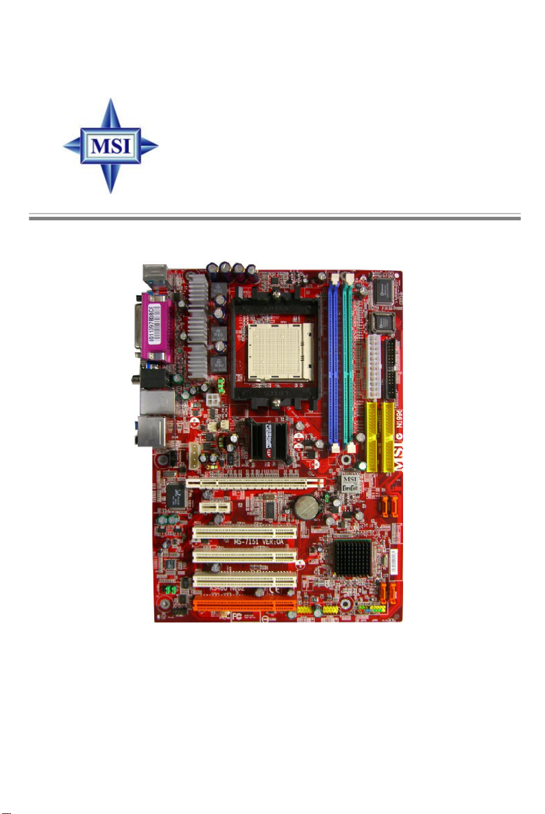
RX480 Neo2
MS-7151 (v1.X) ATX Mainboard
English/French/German Version
G52-M7151X4
i
Page 2
FCC-B Radio Frequency Interference Statement
This equipment has been tested and found to comply with the limits for a class B
digital device, pursuant to part 15 of the FCC rules. These limits are designed to
provide reasonable protection against harmful interference when the equipment is
operated in a commercial environment. This equipment generates, uses and can
radiate radio frequency energy and, if not installed and used in accordance with the
instruction manual, may cause harmful interference to radio communications. Operation of this equipment in a residential area is likely to cause harmful interference, in
which case the user will be required to correct the interference at his own expense.
Notice 1
The changes or modifications not expressly approved by the party responsible for
compliance could void the user’s authority to operate the equipment.
Notice 2
Shielded interface cables and A.C. power cord, if any, must be used in order to
comply with the emission limits.
VOIR LA NOTICE D’INSTALLATION AVANT DE RACCORDER AU RESEAU.
Micro-Star International
MS-7151
This device complies with Part 15 of the FCC Rules. Operation is subject to the
following two conditions:
(1) this device may not cause harmful interference, and
(2) this device must accept any interference received, including interference that may
cause undesired operation.
ii
Page 3

Copyright Notice
The material in this document is the intellectual property of MICRO-STAR
INTERNATIONAL. We take every care in the preparation of this document, but no
guarantee is given as to the correctness of its contents. Our products are under
continual improvement and we reserve the right to make changes without notice.
Trademarks
All trademarks are the properties of their respective owners.
AMD, Athlon™, Athlon™ XP, Thoroughbred™, and Duron™ are registered trade-
marks of AMD Corporation.
Intel® and Pentium® are registered trademarks of Intel Corporation.
PS/2 and OS®/2 are registered trademarks of International Business Machines
Corporation.
Windows® 95/98/2000/2003/NT/XP are registered trademarks of Microsoft Corporation.
Netware® is a registered trademark of Novell, Inc.
Award® is a registered trademark of Phoenix Technologies Ltd.
AMI® is a registered trademark of American Megatrends Inc.
Revision History
Revision Revision History Date
V1.0 First Release of 7151 v1.x PCB August 2005
V1.1 First Release of 7151 v1.x PCB November 2005
with ATI RX480/SB400 chipsets
with ATI RX480/SB400 chipsets (for EU)
Technical Support
If a problem arises with your system and no solution can be obtained from the user’ s
manual, please contact your place of purchase or local distributor. Alternatively,
please try the following help resources for further guidance.
Visit the MSI website for FAQ, technical guide, BIOS updates, driver updates,
and other information: http://www.msi.com.tw/program/service/faq/
faq/esc_faq_list.php
Contact our technical staff at: support@msi.com.tw
iii
Page 4

Safety Instructions
1. Always read the safety instructions carefully.
2. Keep this User’s Manual for future reference.
3. Keep this equipment away from humidity.
4. Lay this equipment on a reliable flat surface before setting it up.
5. The openings on the enclosure are for air convection hence protects the equipment from overheating. DO NOT COVER THE OPENINGS.
6. Make sure the voltage of the power source and adjust properly 110/220V before connecting the equipment to the power inlet.
7. Place the power cord such a way that people can not step on it. Do not place
anything over the power cord.
8. Always Unplug the Power Cord before inserting any add-on card or module.
9. All cautions and warnings on the equipment should be noted.
10. Never pour any liquid into the opening that could damage or cause electrical
shock.
11. If any of the following situations arises, get the equipment checked by a service
personnel:
† The power cord or plug is damaged.
† Liquid has penetrated into the equipment.
† The equipment has been exposed to moisture.
† The equipment has not work well or you can not get it work according to
User’s Manual.
† The equipment has dropped and damaged.
† The equipment has obvious sign of breakage.
12. DO NOT LEAVE THIS EQUIPMENT IN AN ENVIRONMENT UNCONDITIONED, STORAGE TEMPERATURE ABOVE 600 C (1400F), IT MAY DAMAGE THE EQUIPMENT.
CAUTION: Danger of explosion if battery is incorrectly replaced.
Replace only with the same or equivalent type recommended by the
manufacturer.
iv
Page 5
WEEE Statement
v
Page 6
vi
Page 7
vii
Page 8

CONTENTS
FCC-B Radio Frequency Interference Statement...........................................................ii
Copyright Notice.............................................................................................................iii
Revision History.............................................................................................................iii
Technical Support.........................................................................................................iv
Safety Instructions........................................................................................................iv
English.......................................................................................................................E-1
User’s Manual.......................................................................................................E-3
Français....................................................................................................................F-1
Manuel d’utilisation...............................................................................................F-3
Deutsch....................................................................................................................G-1
Benutzerhandbuch.............................................................................................G-3
viii
Page 9

User’s Manual
RX480 Neo2 Series
User’s Manual
English
E-1
Page 10

MS-7151 ATX Mainboard
E-2
Page 11

User’s Manual
Chapter 1. Getting
RX480 Neo2 Series
Started
User’s Manual
Thank you for choosing the RX480 Neo2 (MS-7151 v1.X) ATX
mainboard. The RX480 Neo2 mainboard is based on ATi® RX480 &
ATi® SB400 chipsets for optimal system efficiency. Designed to fit the
advanced AMD® K8 Athlon 64 FX processor, the RX480 Neo2 delivers a high performance and professional desktop platform solution.
E-3
Page 12

MS-7151 ATX Mainboard
Mainboard Specifications
CPU
† Supports 64-bit AMD® Athlon 64 and Athlon 64 FX processor (Socket 939)
† Supports up to 4200+ Athlon 64 FX or higher CPU
(For the latest information about CPU, please visit http://www.msi.com.tw/program/products/mainboard/mbd/pro_mbd_cpu_support.php)
Chipset
† ATI® RX480 Chipset
- HyperTransportTM connection to AMD K8 Athlon64 processor
- 8 or 16 bit control/address/data transfer both directions
- 1000/800/600/400/200 MHz “Double Data Rate” operation both direction
- Compliant with PCI Express 1.0a specifications (one x16 graphics interface,
which can be divided into two smaller links for use by other devices)
† ATI® SB400 Chipset
- Supports dual channel native SATA controller up to 150MB/s with RAID 0 or 1
- Integrated Hardware Sound Blaster/Direct Sound AC97 audio
- Ultra DMA 66/100/133 master mode PCI EIDE controller
- ACPI & PC2001 compliant enhanced power management
- Supports USB2.0 up to 8 ports
Main Memory
† Supports dual channel, four memory banks DDR 333/400, using two 184-pin
DDR DIMMs
† Supports a maximum memory size up to 2GB without ECC
† Supports 2.5v DDR SDRAM DIMM
(For the updated supporting memory modules, please visit http://www.msi.com.
tw/program/products/mainboard/mbd/pro_mbd_trp_list.php.)
Slots
† One PCI Express x16 slot (supports PCI Express Bus specification v1.0a compliant)
† One PCI Express x1 slot
† Four 32-bit Master 3.3V/5V PCI Bus slots
Onboard IDE
† An IDE controller on the ATI® SB400 chipset provides IDE HDD/CD-ROM with PIO,
Bus Master and Ultra DMA 133/100/66 operation modes, 4X ultra DMA 100/66/33
† Can connect up to 4 IDE devices
Onboard Serial ATA
† Supports 4 SATA ports with up to 150MB/s transfer rate
E-4
Page 13

User’s Manual
MSI Reminds You...
1.Please note that users cannot install OS, either WinME or Win98,
in their SATA hard drives. Under these two OSs, SATA can only be
used as an ordinary storage device.
2.To create a bootable RAID volume for a Windows 2000 environment,
Microsoft’s Windows 2000 Service Pack 4 (SP4) is required. As
the end user cannot boot without SP4, a combination installation
CD must be created before attempting to install the operating system onto the bootable RAID volume.
To create the combination installation CD, please refer to the following website:
http://www.microsoft.com/windows2000/downloads/
servicepacks/sp4/HFdeploy.htm
USB Interface
† 8 USB ports
- 4 ports in the rear I/O, 4 ports via the external bracket
LAN (optional)
† Realtek® 8100C/8110SB LAN chip (Optional)
- Integrated Fast Ethernet MAC and PHY in one chip
- Supports 10Mb/s and 100Mb/s and 1000Mb/s (1000Mb/s for 8110SB only)
- Compliance with PCI v2.2
- Supports ACPI Power Management
Audio
† 8 channels software audio codec RealTek ALC850
- Compliance with AC97 v2.3 Spec.
- Meets PC2001 audio performance requirement.
On-Board Peripherals
† On-Board Peripherals include:
- 1 floppy port supports 1 FDD with 360K, 720K, 1.2M, 1.44M and 2.88Mbytes
- 2 serial ports (COM1 on the rear, COM2 with pinheader)
- 1 parallel port supporting SPP/EPP/ECP mode
- 8 USB2.0 ports (Rear*4/Front*4)
- 1 Audio (Line-Outx3, Line-In, MIC In, SPDIF Out (Coaxial/Fibre) port
- 1 RJ-45 LAN Jack
- 2 IDE ports support 4 IDE devices
- 4 serial ATA ports
BIOS
† The mainboard BIOS provides “Plug & Play” BIOS which detects the peripheral
devices and expansion cards of the board automatically.
† The mainboard provides a Desktop Management Interface (DMI) function which
E-5
Page 14

MS-7151 ATX Mainboard
records your mainboard specifications.
† Supports boot from LAN, USB Device 1.1 & 2.0, and SATA HDD.
Dimension
† ATX Form Factor: 30.5cm X 21.5cm
Mounting
† 6 mounting holes
E-6
Page 15
User’s Manual
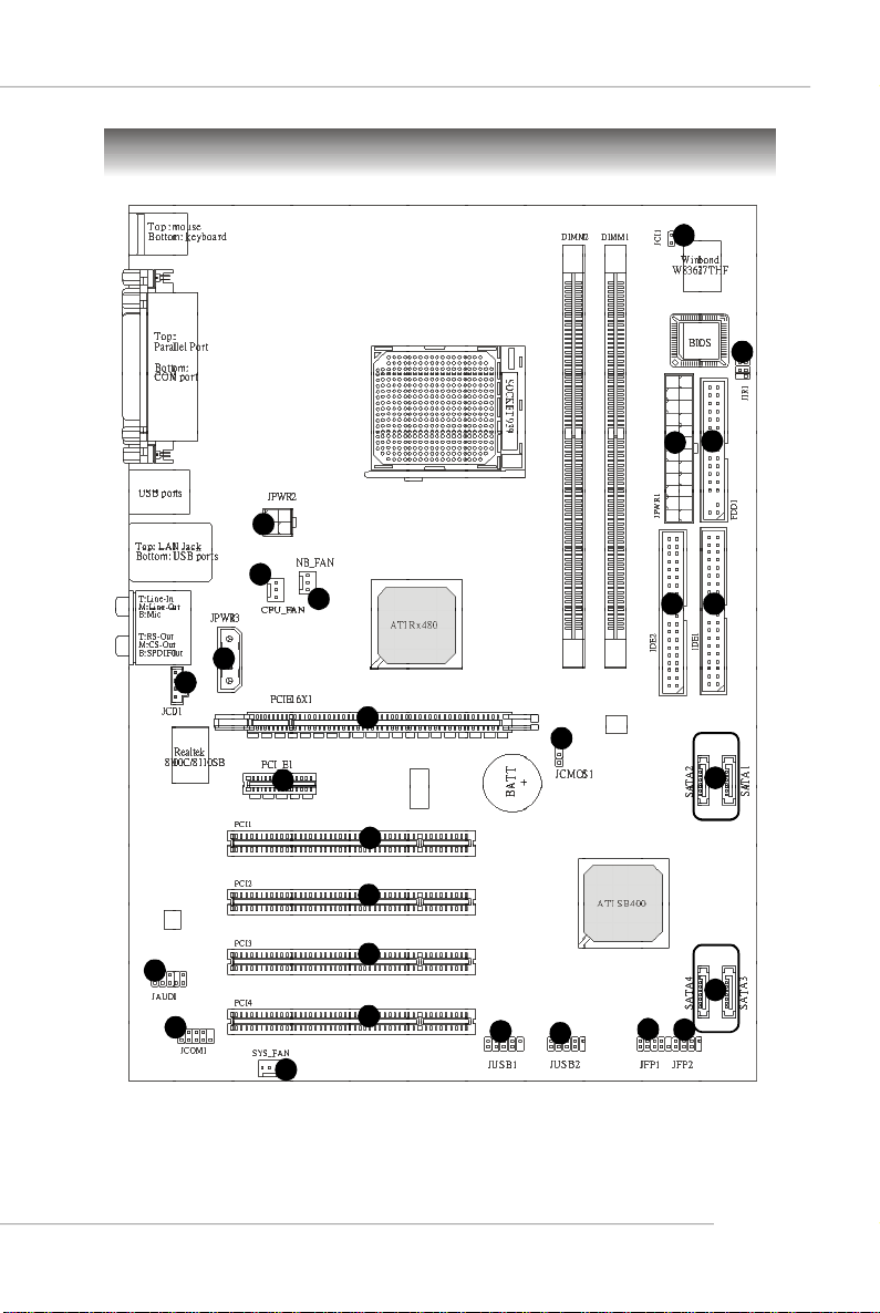
Mainboard Layout
7
12
3
1
2
4
4
2
8
15
14
5 5
15
16
16
9
10
4
16
16
13
RX480 Neo2 (MS-7151 v1.X) ATX Mainboard
13
6
6
1111
E-7
Page 16

MS-7151 ATX Mainboard
1
ATX 24-Pin Power Connector: JPWR1 This connector allows you to
connectto an ATX power suply.
2
ATX 12V Power Connector: JPWR2, JPWR3 This power connector is
provided to connect 12V power suply.
Floppy Disk Drive Connector: FDD1 This mainboard provides a stand-
3
ard floppy disk drive connector that supports 360K, 720K, 1.2M, 1.44M and
2.88M floppy disk types.
4
Fan Power Connecors: CPU_FAN, NB_FAN, SYS_FAN These fan
connectors support system cooling fan with +12V.
ATA 133 Hard Disk Connectors: IDE1 & IDE2 This mainboard has a 32-
5
bit Enhanced PCI IDE and Ultra DMA 66/100/133 controller that provides PIO
mode 0~4, Bus Master and Ultra DMA 66/100/133 function.
6
Serial ATA/ Serial ATA Connectors controlled by ATI SB400: SATA1 /
SATA2 / SATA3 / SATA4 The chipset of this mainboard is SB400 which
supports four serial ATA connectors SATA1~SATA4. SATA1~SATA4 are
high-speed Serial ATA interface ports. Each supports serial ATA data rate
of 150 MB/s.
7
Chassis Intrusion Switch Connector: JCI1 This connector is con-
nected to a 2-pin chassis switch. If the chassis is opened, the switch will
be short.
8
CD-In Connector: JCD1 The connector is for CD-ROM audio connector.
Front Panel Audio Connector: JAUD1 This front panel audio connector
9
allows you to connect to the front panel audio.
10
Serial Port Header: JCOM1 (Optional) The mainboard offers one 9-pin
header as serial port to attach a serial mouse or other serial devices.
Front Panel Connectors: JFP1, JFP2 The mainboard provides one front
11
panel connector for electrical connection to the front panel switches and
LEDs.
2
1
Power
LED
HDD
LED
Power
Switch
Reset
Switch
Speaker
10
JFP1
9
JFP2
2
1
Power LED
8
7
E-8
Page 17

User’s Manual
IrDA Infrared Module Header: JIR1 The connector allows you to
12
connect to IrDA Infrared module. You must configure the setting through
the BIOS setup to use the IR function. JIR1 is compliant with Intel Front
Panel I/O Connectivity Design Guide.
13
Front USB Connectors: JUSB1, JUSB2 This mainboard provides two
standard USB2.0 pin headers that allow you to connect USB devices via
an external USB bracket.
Clear CMOS Jumper: JCMOS1 There is a CMOS RAM onboard that has
14
a power supply from external battery to keep the data of system
configuration. With the CMOS RAM, the system can automatically boot OS
every time it is turned on. If you want to clear the system configuration, set
the JCMOS1 (Clear CMOS Jumper ) to clear data.
PCI Express slots: PCIE16X1 , PCI_ E1 The PCI Express slots support
15
high-bandwidth, low pin count, and serial interconnect technology. You
can insert the expansion cards to meet your needs. When adding or
removing expansion cards, make sure that you unplug the power supply
first. PCI Express architecture provides a high performance I/O infrastructure for Desktop Platforms with transfer rates starting at 2.5 Giga transfers
per second over a PCI Express x1 lane for Gigabit Ethernet, TV Tuners,
1394 controllers, and general purpose I/O. Also, desktop platforms with PCI
Express Architecture will be designed to deliver highest performance in
video, graphics, multimedia and other sophisticated applications. Moreover,
PCI Express architecture provides a high performance graphics infrastructure for Desktop Platforms doubling the capability of existing AGP 8x
designs with transfer rates of 4.0 GB/s over a PCI Express x16 lane for
graphics controllers, while PCI Express x1 supports transfer rate of 250
MB/s.
PCI Slots The PCI slots allow you to insert the expansion cards to meet
16
your needs. When adding or removing expansion cards, make sure that
you unplug the power supply first.
E-9
Page 18

MS-7151 ATX Mainboard
Central Processing Unit: CPU
The mainboard supports AMD® Athlon64 processor. The mainboard uses a
CPU socket called Socket-939 for easy CPU installation. When you are installing
the CPU, make sure the CPU has a heat sink and a cooling fan attached on
the top to prevent overheating. If you do not have the heat sink and cooling
fan, contact your dealer to purchase and install them before turning on the
computer.
For the latest information about CPU, please visit http://www.msi.com.tw/program/products/mainboard/mbd/pro_mbd_cpu_support.php.
MSI Reminds You...
Overheating
Overheating will seriously damage the CPU and system, always make
sure the cooling fan can work properly to protect the CPU from
overheating.
Replacing the CPU
While replacing the CPU, always turn off the ATX power supply or
unplug the power supply’s power cord from grounded outlet first to
ensure the safety of CPU.
E-10
Page 19
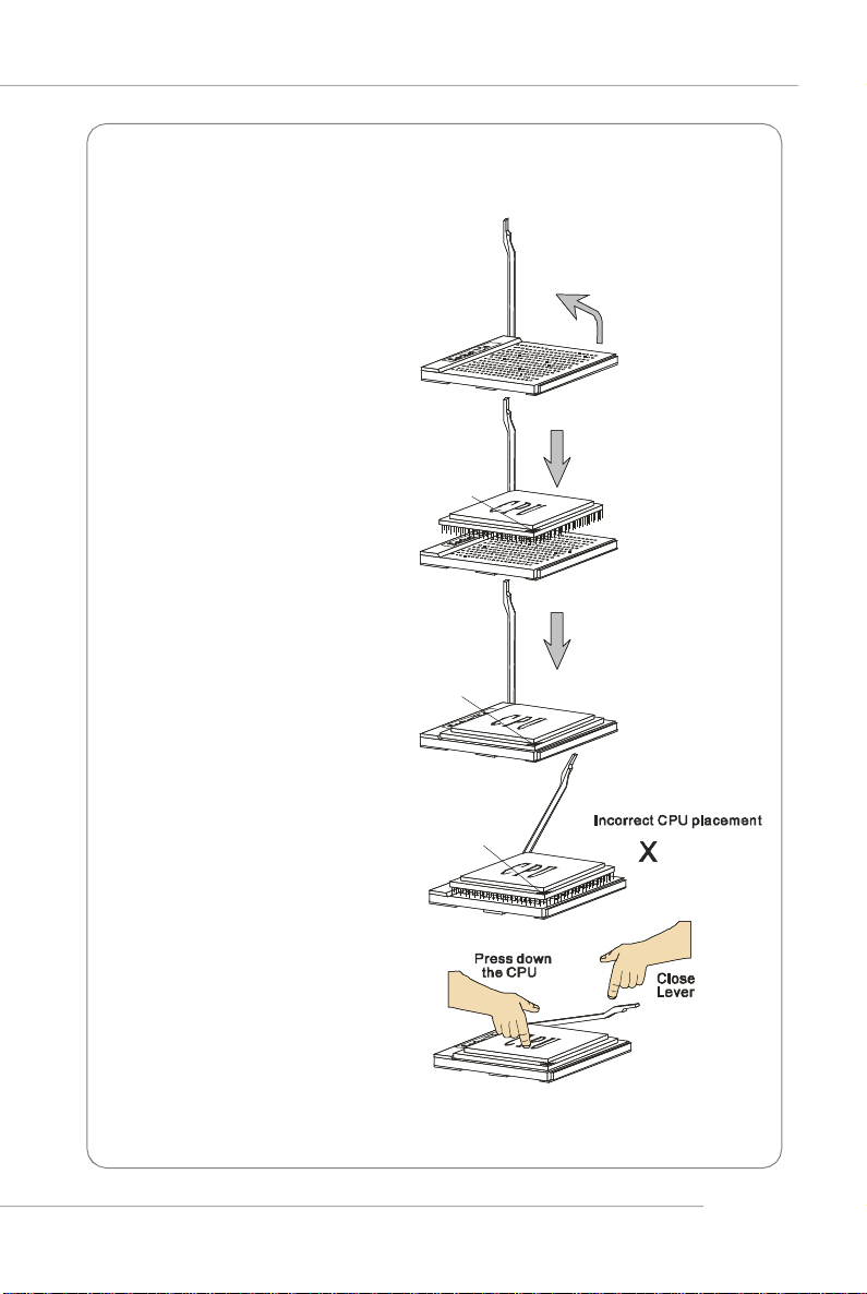
CPU Installation Procedures for Socket 939
Gold arrow
Gold arrow
Gold arrow
Correct CPU placement
O
User’s Manual
1.Please turn off the power and
unplug the power cord before
installing the CPU.
2.Pull the lever sideways away
from the socket. Make sure to
raise the lever up to a 90degree angle.
3.Look for the gold arrow of the
CPU. The gold arrow should
point as shown in the picture.
The CPU can only fit in the
correct orientation.
4.If the CPU is correctly installed,
the pins should be completely
embedded into the socket and
can not be seen. Please note
that any violation of the correct
installation procedures may
cause permanent damages to
your mainboard.
Sliding
Plate
Open Lever
90 degree
5. Press the CPU down firmly into
the socket and close the lever.
As the CPU is likely to move
while the lever is being closed,
always close the lever with
your fingers pressing tightly on
top of the CPU to make sure
the CPU is properly and
completely embedded into the
socket.
E-11
Page 20
MS-7151 ATX Mainboard
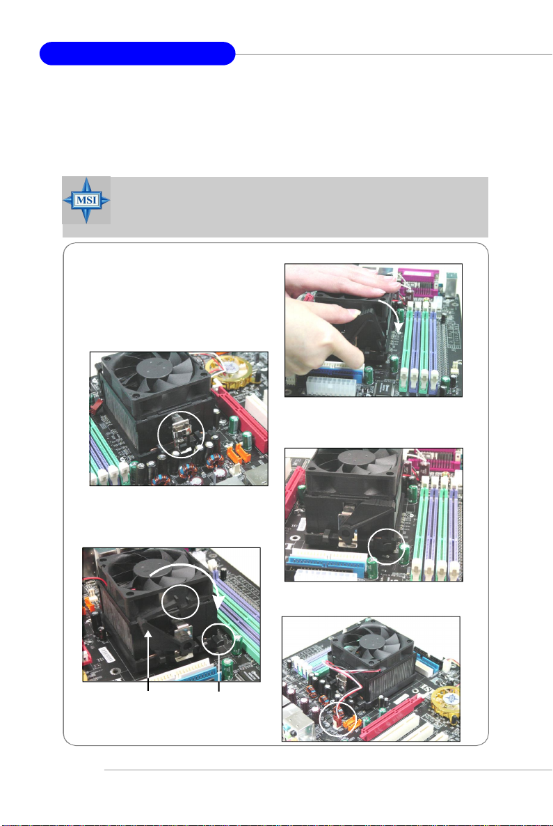
Installing AMD Athlon64 CPU Cooler Set
When you are installing the CPU, make sure the CPU has a heat sink
and a cooling fan attached on the top to prevent overheating. If you do not
have the heat sink and cooling fan, contact your dealer to purchase and install
them before turning on the computer.
MSI Reminds You...
Mainboard photos shown in this section are for demonstration of the
cooler installation for Socket 939 CPUs only. The appearance of
your mainboard may vary depending on the model you purchase.
1.Position the cooling set onto the
retention mechanism.
Hook one end of the clip to hook
first, and then press down the
other end of the clip to fasten the
cooling set on the top of the
retention mechanism.
2.Locate the Fix Lever, Safety Hook
and the Fixed Bolt.
Lift up the intensive fixed lever.
Safety Hook
3.Fasten down the lever.
4.Make sure the safety hook completely clasps the fixed bolt of the
retention mechanism.
5.Attach the CPU Fan cable to the CPU
fan connector on the mainboard.
E-12
Fixed Lever
Fixed Bolt
Page 21
User’s Manual
Memory
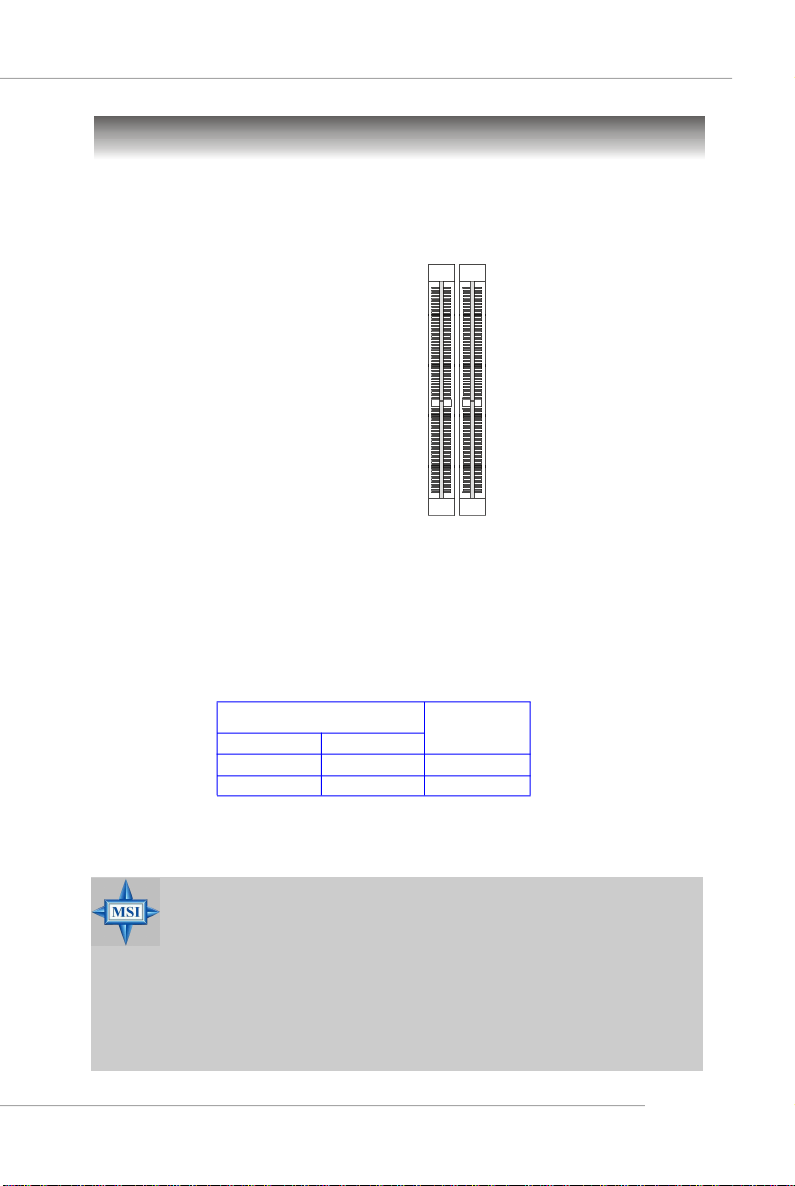
The mainboard provides 2 slots for 184-pin DDR DIMM (Double In-Line Memory
Module) modules and supports the memory size up to 2GB. You can install DDR 333/
400 modules on the DDR DIMM slots (DIMM 1~2).
DIMM1~DIMM2
(from right to left)
DIMM Module Combination
Install at least one DIMM module on the slots. Each DIMM slot supports up to a
maximum size of 1GB. Users can install either single- or double-sided modules to
meet their own needs. Users may install memory modules of different type and
density on different-channel DDR DIMMs. However, memory modules of the same
type and density are required while using dual-channel DDR, or instability may
happen.
Slots
DIMM1 (CH A) DIMM2 (CH B) Mode
128MB~1GB Single Channel
128MB~1GB 128MB~1GB Dual Channel
MSI Reminds You...
- The system operates ONLY when the DDR modules are installed in
accordance with the above-mentioned memory population rules.
- In dual-channel mode, make sure that you install memory modules
of the same type and density on DDR DIMMs.
- To enable successful system boot-up, always insert the memory
modules into the Channel A slots (DIMM1) first.
- This mainboard DO NOT support the memory module installed
with more than 18 pieces of IC (integrated circuit).
E-13
Page 22
MS-7151 ATX Mainboard
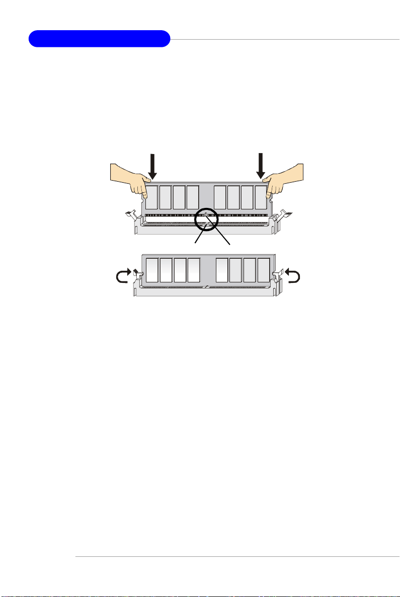
Installing DDR Modules
1. The DDR DIMM has only one notch on the center of module. The module will
only fit in the right orientation.
2. Insert the DIMM memory module vertically into the DIMM slot. Then push it in
until the golden finger on the memory module is deeply inserted in the socket.
3. The plastic clip at each side of the DIMM slot will automatically close.
Volt
Notch
E-14
Page 23
User’s Manual
Restore the previous CMOS value from CMOS, only for Option Page
BIOS Setup
Power on the computer and the system will start POST (Power On Self Test)
process. When the message below appears on the screen, press <DEL> key to
enter Setup.
If the message disappears before you respond and you still wish to enter
Setup, restart the system by turning it OFF and On or pressing the RESET button.
You may also restart the system by simultaneously pressing <Ctrl>, <Alt>, and
<Delete> keys.
Control Keys
<↑>
<↓>
<←> Move to the item in the left hand
<→> Move to the item in the right hand
<Enter> Select the item
<Esc> Jumps to the Exit menu or returns to the main menu from a submenu
<+/PU> Increase the numeric value or make changes
<-/PD> Decrease the numeric value or make changes
<F1> General help, only for Status Page Setup Menu and Option Page
<F5>
<F6> Load the default CMOS value from Fail-Safe default table, only for
<F7> Load Optimized defaults
<F10> Save all the CMOS changes and exit
Press DEL to enter SETUP
Move to the previous item
Move to the next item
Setup Menu
Setup Menu
Option Page Setup Menu
Getting Help
After entering the Setup menu, the first menu you will see is the Main Menu.
Main Menu
The main menu lists the setup functions you can make changes to. You can
use the control keys ( ↑↓ ) to select the item. The on-line description of the highlighted
setup function is displayed at the bottom of the screen.
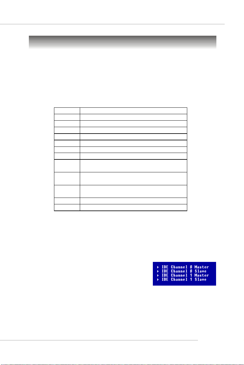
Sub-Menu
If you find a right pointer symbol (as shown in the
right view) appears to the left of certain fields that means
a sub-menu containing additional options can be launched
from this field. You can use control keys ( ↑↓ ) to
highlight the field and press <Enter> to call up the submenu. Then you can use the control keys to enter values and move from field to field within a sub-menu. If you want to return to the main
menu, just press <Esc >.
General Help <F1>
The BIOS setup program provides a General Help screen. You can call up this
screen from any menu by simply pressing <F1>. The Help screen lists the appropriate
keys to use and the possible selections for the highlighted item. Press <Esc> to exit
the Help screen.
E-15
Page 24
MS-7151 ATX Mainboard
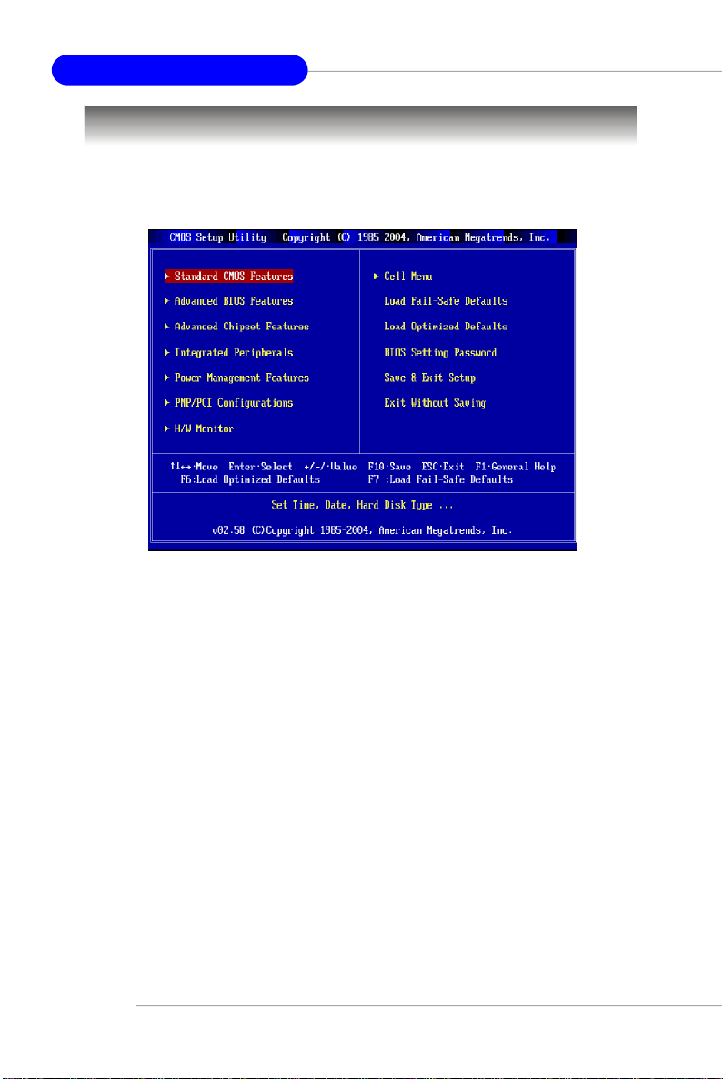
The Main Menu
Once you enter AMIBIOS NEW SETUP UTILITY, the Main Menu will appear on the
screen. Use arrow keys to move among the items and press <Enter> to enter the
sub-menu.
Standard CMOS Features
Use this menu for basic system configurations, such as time, date etc.
Advanced BIOS Features
Use this menu to setup the items of AMI® special enhanced features.
Advanced Chipset Features
Use this menu to change the values in the chipset registers and optimize your system’s
performance.
Integrated Peripherals
Use this menu to specify your settings for integrated peripherals.
Power Management Features
Use this menu to specify your settings for power management.
PNP/PCI Configurations
This entry appears if your system supports PnP/PCI.
H/W Monitor
This entry shows the status of your CPU, fan, warning for overall system status.
E-16
Page 25

User’s Manual
Cell Menu
Use this menu to specify your settings for frequency/voltage control.
Load Fail-Safe Defaults
Use this menu to load the default values set by the BIOS vendor for stable system
performance.
Load Optimized Defaults
Use this menu to load the default values set by the mainboard manufacturer
specifically for optimal performance of the mainboard.
BIOS Setting Password
Use this menu to set the password for BIOS.
Save & Exit Setup
Save changes to CMOS and exit setup.
Exit Without Saving
Abandon all changes and exit setup.
E-17
Page 26

MS-7151 ATX Mainboard
Advanced Chipset Features
MSI Reminds You...
Change these settings only if you are familiar with the chipset.
DRAM Timing
The value in this field depends on performance parameters of the installed memory
chips (DRAM). Do not change the value from the factory setting unless you install
new memory that has a different performance rating than the original DRAMs.
CAS Latency (CL)
This controls the CAS latency, which determines the timing delay (in clock cycles)
before SDRAM starts a read command after receiving it. Settings: [2.0], [2.5], [3.
0]. [2.0] increases the system performance the most while [3.0] provides the
most stable performance.
TRAS
This setting determines the time RAS takes to read from and write to a memory
cell. Setting options: [5CLK] to [15CLK].
TRP
This setting controls the number of cycles for Row Address Strobe (RAS) to be
allowed to precharge. If insufficient time is allowed for the RAS to accumulate its
charge before DRAM refresh, refresh may be incomplete and DRAM may fail to
retain data. This item applies only when synchronous DRAM is installed in the
system. Setting options: [2CLK] to [6CLK].
TRCD
When DRAM is refreshed, both rows and columns are addressed separately.
This setup item allows you to determine the timing of the transition from RAS (row
address strobe) to CAS (column address strobe). The less the clock cycles, the
faster the DRAM performance. Setting options: [2CLK] to [6CLK].
Bank Interleaving
This field selects 2-bank or 4-bank interleave for the installed SDRAM. Disable the
function if 16MB SDRAM is installed. Settings: [Auto], [Disabled].
E-18
Page 27

User’s Manual
PNP/PCI Configurations
This section describes configuring the PCI bus system and PnP (Plug & Play) feature.
PCI, or Peripheral Component Interconnect, is a system which allows I/O devices to
operate at speeds nearing the speed the CPU itself uses when communicating with
its special components. This section covers some very technical items and it is
strongly recommended that only experienced users should make any changes to the
default settings.
Primary Graphic’s Adapter
This setting specifies which VGA card is your primary graphics adapter. Setting
options are:
[Auto] The system initializes the graphic’s adapter automatically.
[PCI Mode]The system initializes the PCI Express graphic first. If a PCI Express
graphic card is not available, it will initialize the internal graphic’s
adapter.
E-19
Page 28

MS-7151 ATX Mainboard
H/W Monitor
This section shows the status of your CPU, fan, overall system status, etc. Monitor
function is available only if there is hardware monitoring mechanism
CPU Shutdown Temperature
If the CPU temperature reaches the limit preset in the next setting, the system will
shutdown automatically. This helps you to prevent the CPU overheating problem.
This item is available only when your OS supports this function, such as Windows
ME/XP. Setting options: [Disabled], [75
O
C]. [80OC], [85OC].
CPU Fan Failure Warning
When enabled, the system will automatically monitor the CPU fan during boot-up. If it
detects that the CPU fan is not rotating, the system will show an error message on
the screen and halt the boot-up process. The function is built with CPU fan power
connector (CPU_FAN) only and enables you to protect the CPU from possible
overheating problem. If you don’t connect the CPU fan to the CPU fan power connector,
we recommend disabling this feature. Setting options: [Enabled], [Disabled].
Chassis Intrusion
The field enables or disables the feature of recording the chassis intrusion status
and issuing a warning message if the chassis is once opened. This item is
available only when your mainboard has JCI1 jumper. To clear the warning
message, set the field to [Reset]. The setting of the field will automatically return to
[Enabled] later. Settings: [Enabled], [Reset], [Disabled].
Smart Fan
When the current temperature of the CPU fan reaches the value you specify here,
the CPU fan will speed up for cooling down to avoid the CPU damage; on the contrary,
if the CPU fan current temperature is lower than the specified value, the CPU fan will
slow down its speed to keep the temperature stable.
E-20
Page 29

User’s Manual
Smart FAN Tolerance
This item allows you to set the tolerance value of the smart fan.
PC Health Status
Press <Enter> and the following sub-menu appears:
CPU/System Temperature, SYSTEM FAN/CPU FAN Speed, Vcore, +3.3V,
+5.0V, +12.0V, +5VSB
These items display the current status of all of the monitored hardware
devices/components such as CPU voltages, temperatures and all fans’
speeds.
E-21
Page 30

MS-7151 ATX Mainboard
Cell Menu
The items in Cell Menu includes some important settings of CPU, AGP, DRAM and
overclocking functions.
MSI Reminds You...
Change these settings only if you are familiar with the chipset.
Current CPU Clock, Current DDR Memory Frequency
These two items show the current clocks of CPU & DDR memory frequency. Readonly.
Cool’n’Quiet
This feature is especially desiged for AMD Athlon processor, which provides a CPU
temperature detecting function to prevent your CPU’s from overheading due to the
heavy working loading. Setting options: [Disabled], [Enabled].
MSI Reminds You...
For the purpose of ensuring the stability of Cool'n'Quiet function, it is
always recommended to have the memories plugged in DIMM1.
Adjust DDR Memory Frequency
User can place an artificial memory clock limit on the system. Please note that memory
is prevented from running faster than this frequency. Setting options:[Manual], [Auto].
DDR Memory Frequency
This read-only item shows the DDR Memory Frequency you like to use, which will
E-22
Page 31

User’s Manual
automatically change in accordance with the setting of Adjust DDR Memory
Frequency. Please note you must reboot the system to let the change take effect.
Setting options: [100 MHz], [133MHz], [166MHz], [200MHz].
Adjust CPU FSB Frequency
This item allows you to select the CPU Front Side Bus clock frequency (in MHz)
and overclock the processor by adjusting the FSB clock to a higher frequency.
Setting options: [200]~[320]
Adjust PCI Express Frequency
User can place an artificial PCI Express clock limit on the system. Setting options:
[100]~[200].
Ratio/Vcore Change
This field allows you to select the CPU Ratio. Setting to [Auto] enables CPU Ratio
automatically to be determined by SPD. Setting options: [Auto], [Manual].
Adjust CPU Ratio
This item allows you to adjust the CPU ratio. Setting to [Startup] enables the
CPU running at the fastest speed which is detected by system. Setting options
are: [Startup], [x4]~[x25].
CPU Voltage
The settings are used to adjust the CPU clock multiplier (ratio) and CPU corevoltage
(Vcore). These settings offer users a tool to overclock the system.
Memory Voltage
Adjusting the DDR voltage can increase the DDR speed. Any changes made to this
setting may cause a stability issue, so changing the DDR voltage for long-term
purpose is NOT recommended.
LDT Bus Voltage
This item specifies the maximum operating frequency of the link's transmitter clock.
Setting options: [1.20], [1.25], [1.30], [1.35], [1.40], [1.45], [1.50].
Auto Disable PCI Clock
This item is used to auto detect the PCI slots. When set to [Enabled], the system will
remove (turn off) clocks from empty PCI slots to minimize the electromagnetic interference (EMI). Settings: [Enabled], [Disabled].
Spread Spectrum
When the motherboard’s clock generator pulses, the extreme values (spikes) of the
pulses creates EMI (Electromagnetic Interference). The Spread Spectrum function
reduces the EMI generated by modulating the pulses so that the spikes of the pulses
are reduced to flatter curves. If you do not have any EMI problem, leave the setting at
[Disabled] for optimal system stability and performance. But if you are plagued by EMI,
activate the Spread Spectrum for EMI reduction. Remember to disable Spread Spectrum if you are overclocking because even a slight jitter can introduce a temporary
E-23
Page 32

MS-7151 ATX Mainboard
boost in clock speed which may just cause your overclocked processor to lock up.
Options: [Disabled], [Enabled].
MSI Reminds You...
The settings shown in different color in CPU Voltage, DDR Voltage and
NB Voltage help to verify if your setting is proper for your system.
Gray: Default setting.
White:Safe setting.
Yellow:High performance setting.
Red: Not recommended setting and the system may be
Changing CPU Voltage, DDR Voltage and NB Voltage may result in the
instability of the system; therefore, it is NOT recommended to change
the default setting for long-term usage.
unstable.
E-24
Page 33

Manual d’utilisation
Les Séries
RX480 Neo2
Manual d’utilisation
Français
F-1
Page 34

La Carte Mère MS-7151 ATX
F-2
Page 35

Manual d’utilisation
Chapter 1. Getting
Started
Les Séries
RX480 Neo2
Manual d’utilisation
Félicitation vous venez d’acheter les Séries RX480 Neo2 (MS-
7151 v1.X) ATX mainboard.une carte mère excellente de MSI. les
Séries RX480 Neo2 sont basées sur les chipset ATi® RX480 & ATi
SB400 pour obtenir un systeme performant. Destiné aux processeus
AMD® K8 Athlon 64 FX processor.Les Séries RX480 Neo2 offrent
de hautes performances tant auxparticuliers qu’aux professionnels.
®
F-3
Page 36

La Carte Mère MS-7151 ATX
Spécificités de la Carte
CPU
† Supporte les processeurs Socket-939 pour AMD® Athlon 64 dans les 64 bit et
Athlon 64 FX
† Supporte jusqu’à 4200+ Athlon 64 FX ou plus haut de CPU
(plus d’information,visitez http://www.msi.com.tw/program/products/mainboard/
mbd/pro_mbd_cpu_support.php)
Chipset
† Chipset ATI® RX480
-Raccordement hyper du transportTM à AMD K8 Athlon64/ Processeur
-8 ou 16 bits contrôleur/adresse/données transferent les deux directions
-1000/800/600/400/200 MHz “Double Débit” opération les deux directions
-Compatible avec PCI Express 1.0a (une interface de graphiques x16, ce qui
peut être divisée en deux plus petits liens à l'usage d'autres dispositifs)
† Chipset ATI® SB400
- Supporte le contrôleur du canal double native SATA jusqu'à 150MB/s
avec RDID 0 ou 1
- Matériel dur integré avec Sound Blaster/Direct Sound AC97 audio
- Ultra PCI EIDE contrôleur principal de mode de DMA 66/100/133
- Compatible avec le power management augmentée d'ACPI& PC2001
- Supporte jusqu’à 8 USB2.0 ports
Mémoire Principale
† Supporte canal double, 4 banques de mémoires.DDR 333/400 ,utilisant deux
184 pin DDR DIMMs
† Supporte une taille de mémoires jusqu' à 2GB au total sans ECC
† Supporte 2.5v DDR SDRAM DIMM
(plus d’information,visitez http://www.msi.com.tw/program/products/
mainboard/mbd/pro_mbd_trp_list.php.)
Slots
† Un slot PCI Express x16 (supporte PCI Express Bus specification v1.0a compliant)
† Un slot PCI Express x 1 (supports PCI Express Bus specification v1.0a compliant)
† Deux 32-bit Master 3.3V/5V PCI Bus slots
IDE Integré
† Un contrôleur IDE sur le chipset ATI® SB400 Plus procure IDE HDD/CD-ROM
avec PIO, Bus Master et les modes opératoires Ultra DMA133/100/66, 4X ultra
DMA 100/66/33
† Peut connecter jusqu’à quatre dispositifs d’IDE.
ATA Série Integr é
† Supporte 4 SATA ports avec le taux de transfer jusqu’à 150MB/s
F-4
Page 37

Manual d’utilisation
MSI Vous Rappelle...
1. Veuillez noter que les utilisateurs ne peuvent pas installer l’OS,
WinME ou Win98, dans leurs commandes dures de SATA. Sous
ces deux OSs, SATA peut seulement être utilisé comme dispositif
de stockage ordinaire.
2.Pour créer un bootable RAID volum pour un environnement de
Windows 2000, Le paquet 4 (SP4) de service de Microsoft Windows 2000 est exigé. Car l’utilisateur ne peut pas initialiser sans
SP4, un CD d’installation de combinaison doit être créé avant
d’essayer d’installer le logiciel d’exploitation sur le bootable RAID
volume. veuillez se référer au site Web suivant :
http://www.microsoft.com/windows2000/downloads/
servicepacks/sp4/HFdeploy.htm
USB Interface
† 8 USB ports
- 4 ports à l’arrière IO, 4 ports par l’intermédiaire de la parenthèse externe
LAN (optional)
† Realtek® 8100C ou 8110SB LAN chip(optionnel)
- Fast Ethernet MAC et PHY integrés dans un chip
- Supporte 10Mb/s, et 100Mb/s à 8110SB jusqu’à 1000Mb/s.
- Compatible avec PCI v2.2
- Supporte ACPI Power Management
Audio
† 8 canaux audio logiciel (codec Realtek ALC850)
- Compatible avec AC97 v2.3 Spec.
- Compatible avec les règlements Audio PC2001.
Périph ériques Intégrés
† Périphériques Intégrés inclut:
- 1 port floppy port supporte 1 FDD avec 360K, 720K, 1.2M, 1.44M et 2.88MB
- 2 port sériel (COM1 sur l'arrière, COM2 avec le pinheader)
- 1 port parallèle supportant les modes SPP/EPP/ECP
- 8 portsUSB2.0 (Arrière, * 4/ Façade * 4)
- 1 connecteur Audio (Line-Outx3, Line-In, MIC In et coaxial/ fibel SPDIF sortie)
- 1 RJ-45 LAN Jacks
- 2 ports IDE supporte 4 IDE devices
- 4 ports ATA série
F-5
Page 38

La Carte Mère MS-7151 ATX
BIOS
† La carte mère utilise un BIOS “Plug & Play” détectant les périphériques ainsi que
les cartes d’extension de façon automatique
† La carte mère offre une fonction DMI (Desktop Management Interface) qui
enregistre les spécifications de la carte mère.
† Supporte boot de LAN, USB Device 1.1 & 2.0, et SATA HDD.
Dimension
† Format Facteur Micro: 30.5cm X 21.5cm
Mounting
† 6 trous de montages
F-6
Page 39

Schéma de la Carte Mère
2
4
4
2
8
15
Manual d’utilisation
7
1
5 5
14
12
3
15
16
16
9
10
4
16
16
13
RX480 Neo2 (MS-7151 v1.X) Carte Mère ATX
13
6
6
1111
F-7
Page 40

La Carte Mère MS-7151 ATX
1
ATConnecteur ATX 24Pin Power : JPWR1. Ce connecteur vous permet
de vous connecter à une alimentation ATX.
2
Connecteur ATX 12V Power : JPW2, JPW3. Ce connecteur est utilisé
pour connecter à une alimentation 12V.
3
Connecteur Floppy Disk Drive : FDD1. La carte mère procure un
connecteur floppy disk drive standard supportant les floppy disk drives de
360K, 720K, 1.2M, 1.44M et 2.88M.
4
Connecteurs Fan Power: CPU_FAN, SYS_FAN,SYS_FAN. Ces Fan
connecteurs supportent le systeme colling fan avec +12V.
5
Connecteurs de disques durs ATA 133 : IDE1 & IDE2. Cette carte
mère possède un contrôleur 32-bit Enhanced PCI IDE et Ultra DMA 66/100/
133 qui procure les fonctions PIO mode 0~4, Bus Master et Ultra DMA 66/
100/133.
6
ATA Série/ ATA Série Connecteurs contrôlés par ATI SB400:
SATA1/ SATA2/ SATA3 / SATA4. Le chipset de cette carte mère est
SB400 qui supporte 4 connecteurs SATA/1~ SATA4. Les connecteurs
supporte SATA rates de 150MB/s .
Connecteur Chassis Intrusion Swith: JCII. Ce connecteur est
7
connecté à un chassis switch 2 broches. Si le chassis est ouvert, le
système enregistrera la statut.
Connecteur CD-In: JCD1. Le connecteur est destiné aux branchements
8
audio du CD-ROM.
9
Connecteur audio Panneau avant: JAUD1. Ce connecteur panneau
avantAudio permet une connection au audio panneau avant.
En-tête De Porte série : JCOM1 (optionnel). La carte mère offre une
10
9-pin en-tête (hearder) comme une série de porte qui vous permet de
connecter une souris serial ou un autre dispositif serial
Connecteurs Panneau avant: JFP1, JFP2. La carte mère procure un
11
connecteur un front panel pour les connections éléctriques de
l’interrupteur en façade et des LEDs.
Power
Power
LED
2
1
HDD
LED
Switch
Reset
Switch
10
JFP1
9
JFP2
Speaker
2
1
Power LED
F-8
8
7
Page 41

Manual d’utilisation
Connecteur Infra rouge IrDA : JIR1. Ce connecteur permet la connec-
12
tion au module infrarouge IrDA. Vous devez configurer les paramètres du
BIOS pour utiliser la fonction IR. JIR1 est compatible avec Intel Front Panel I/
O Connectivity Design Guide.
13
Connecteur Front USB: JUSB1 & JUSB2. Cette carte mère procure deux
connecteurs standards USB2.0 qui vous permet de connecter le dispositif
d’USB via une parenthèse externe d’USB.
14
Bouton Clear CMOS: JCMOS Le CMOS RAM intégré est alimenté par
une batteie extérieur qui garde les données de configuration du système.
Avec le CMOS RAM, le système peut automatiquement booter avec les
paramè tres personnalisés du BIOS chaque fois que le PC est allumé..
15
Slots PCI Express: PCIE16X1 , PCI_ E1
Le slot PCI Express, comme une largeur de bande,un pin basse et compte,
une publication sériele,une technologie d’interconnexion. L’architecture PCI
Express fournit un rendement élevé I/O infrastructure pour les plateformes
de bureau avec un taux de transfert de 2.5 de Giga par seconde sur une
ruelle PCI Express x1pour Gigabit Ethernet, TV Tuners, contrôleurs 1394, et
IO général. En outre, des plateformes de bureau avec l’architecture PCI
Express seront conçues pour fournir le rendement le plus élevé dans la
vidéo, graphiques, multimédia et d’autres applications sophistiquées.
D’ailleurs, L’architecture PCI Express fournit une infrastructure graphique
pour les plateformes de bureau doublant la possibilité d’existante d’AGP8x
avec taux de transfert de 4.0 gigaoctetss pour les contrôleurs graphiques.
Vous pouvez insérer les cartes d’expansion alors que le PCI Express x 1
supporte un taux de transfert de 250 MB/s..
16
PCI Slots: Les slots PCI vous permet de insérer les cartes d’expansion
pour satisfaire vos besoins. En ajoutant ou en enlevant des cartes
d’expansion, assurez-vous que vous débranchez l’alimentation d’énergie
d’abord.
F-9
Page 42

La Carte Mère MS-7151 ATX
Unité centrale De Traitement: CPU
La carte mère supporte les processeurs AMD® Athlon64. La carte utilise un
socket appelé Socket-939. Lors de l’installation du CPU, assurez-vous de bien
installer un dissipateur et un ventilateur afin d’éviter la surchauffe. Si
vous ne savez pas le modèle qu’il vous faut, il est recommandé de prendre contact
avec votre revandeur..
Pour plus d’information,Visitez http://www.msi.com.tw/program/products/
mainboard/mbd/pro_mbd_cpu_support.php.
MSI Vous Rappelle...
Surchauffe
Une surchauffe peut sérieusement endommager le CPU et le système,
assurez vous toujours que le système de reffroidissement fonctionne
correctement pour protéger le CPU d’une surchauffe.
Remplacer le CPU
Avant de remplacer le CPU, éteignez toujours l’alimentation ATX ou
débranchez la prise pour assurer la sécurité du CPU.
F-10
Page 43

Manual d’utilisation
Gold arrow
Gold arrow
Gold arrow
Correct CPU placement
O
Procédure d’installation du CPU pour Socket 939
1. Veuillez éteindre et débrancher
votr e PC avant l’installation du
CPU
2. Tirez le levier vers le haut.
Assurez-vous que celui-ci est
bien en position ouverte
maximum (angle de 90°)
3.Repérez la flèche dorée. La
flèche dorée doit se trouver
comme indiqué sur le dessin.
Le CPU ne peut être installer
que dans un seul sens.
4. Si le CPU est correctement
installé alors les broches ne
sont plus visibles. Une
mauvaise installation pourrait
entraîner des dommages vis-à-
vis de la carte mère
5. Appuyez sur le CPU pendant
que vous abaissez le levier. Il
faut toujours exercer une
pression sur le CPU pour éviter
que ce dernier ne soit pas bien
fixé une fois le levier abaissé.
Sliding
Plate
Open Lever
90 degree
F-11
Page 44

La Carte Mère MS-7151 ATX
Installer le système de refroidissement du CPU AMD Athlon64
Quand vous installerez votre CPU, assurez vous que le CPU possède
un système de reffroidissement pour prévenir les surchauffes. Si vous
ne possédez pas de système de reffroidissement, contactez votre revendeur pour
vous en procurer un et installez le avant d’allumer l’orcinateur.
MSI Vous Rapplle...
Les photos de la carte mère montrées dans cette section sont pour
la démonstration de l’installation plus fraîche seulement pour
Socket 939 CPUs. L’aspect de votre carte mère peut changer selon
le modèle acheté par vous.
1. Positionnez le système de
reffroidissement sur le mécanisme
d’attache. Accrochez une
extrémité de l’aggrafe avant de
tout accrocher.
3. Fixez le levier vers le bas
4.Assurez vous que le crochet de
sécurité soit bien attaché à son
encôche sur lemécanisme
2.Localisez le levier de fixation, et
accrochez le bien sur son
encoche.
Safety Hook
Fixed Lever
Fixed Bolt
F-12
5.Attachez le câble de ventilateur de
CPU au connecteur sur la carte
Page 45

Manual d’utilisation
Mémoire
La carte mère procure 2 slots DDR DIMM (Double In-Line Memory Module)
(184 broches) et supporte jusqu’à 2GB de mémoire. Vous pouvez installer les mod-
ules DDR 333/400 sur les slot DDR DIMM (DIMM 1~2).
DIMM1~DIMM2
(de gauche à droite)
DIMM Module Combination
Installez au moins un module DIMM sur les slots. Les modules de mémoire
peuvent être installés sur les slots dans n'importe quel ordre. Vous pouvez
installer des modules simples ou doubles faces selon vos besoins.Les modules de
mémoire peuvent être installlés dans n'importe quelle combinaison:Cependant, des
modules de mémoire du mêmes type et densité sont exigés tout en en
utilisant DDR à canal double, ou l’instabilité
Slots
DIMM1 (CH A) DIMM2 (CH B) Mode
128MB~1GB Unique Canal
128MB~1GB 128MB~1GB Canal double
MSI Vous Rappelle...
- Le système fonctionne SEULEMENT quand les modules de DDR
sont installés selon les règles mentionnées de population de
mémoire.
- En mode ą canal double, assurez-vous que vous installez des
modules de mémoire du mźmes type et densité sur DDR DIMMs.
- Insertez le module de mémoire dans le Channel A slots (DIMM1
ou DIMM3) d’abord.
- Cette carte mère ne supporte pas les modules de mémoire avec
plus de 18 IC (Circuit Intégré).
F-13
Page 46

La Carte Mère MS-7151 ATX
Installation des modules DDR
1.La DDR DIMM ne posséde qu’une encoche en son centre. Le module ne peut
être monté que dans le bon sens.
2.Insérez le module de mémoire DIMM verticalement dans le slot. Poussez alors le
dedans jusqu'à ce que le doigt d'or sur le module de mémoire soit profondément
inséré dans la douille.
3. . Le clip en plastique situé de chaque coté du module va se fermer
automatiquement
Volt
Notch
F-14
Page 47

Manual d’utilisation
Installation du BIOS
Allumez votre ordinateur, le système lance le processus de POST (Power
On Self Test). Quand le message ci-dessous apparaît à l’écran, appuyez sur le
bouton <DEL> pour entrer dans le setup.
Si le message disparaît avant que vous ne puissiez entrer dans le setup,
redémarrez votre ordinateur en appuyant sur le bouton RESET. Vous pouvez aussi
utiliser simultanément la combinaison de touches : <Ctrl>, <Alt>, et <Delete>.
Touches de Contrôl
<↑>
<↓>
<←>
<→>
<Enter> Séléctoinner le champ.
<Esc> Quitter ou retourner au menu principal.
<+/PU> Augmente la valeur numérique ou change l’option.
<-/PD> Diminue la valeur numérique ou change l’ option.
<F1> Aide générale, seulement pour Status Page Setup Menu ou Option Page Setup Menu
<F5> Restaure la précédente valeur du CMOSO.Pour option Page Setup Menu
<F6> Charge les valeurs optimisés par défaut
<F7> Charge les valeurs de Fail-Safe
<F10> Sauve toute les mofications du CMOS et quitte.
Aide
Une fois dans le Setup, le 1er écran est celui du menu principal.
Menu Principal
Le menu principal affiche les différentes catécories du BIOS, utilisez les
fleches( ↑↓ )Pours sélectionner l’article. La description en ligne de la fonction
accentuée d’installation est montrée au fond de l’écran.
Sous-Menu
Si vous trouvez un bon symbole d’indicateur (montré à sa
juste place ) apparaît à la gauche de certains champs,
cela signifie que un sous-menu peut être lancé de ce
champ. Un sous-menu contient des options
additionnelles pour un paramètre de champ. Avec les
touches de déplacement( ↑↓ ) pour présenter le
champ ou presser< entrent > pour appeler le sousmenu. Alors vous pouvez déplacer du champ au champ dans un sous-menu. Si
vous voulez retourner au menu principal, pressez juste < ESC >.
Aide Générale < F1 >
Le programme d’installation de BIOS fournit un écran général d’aide. Vous pouvez
appeler cet écran de tout menu par la pression de< F1 >. L’écran d’aide vous
donne des choix possibles pour la convenance. Pressez< ESC > pour sortir
l’écran d’aide.
Se déplacer au champ précé dent.
Se déplacer au champ suivant.
Se déplacer au champ sur la gauche.
Se déplacer au champ sur la droite.
Press DEL to enter SETUP
F-15
Page 48

La Carte Mère MS-7151 ATX
Menu Principal
Une fois entré dans le AMI® BIOS CMOS Setup Utility, Le menu apparaît à
l’écran. Utilisez les flèches pour vous diriger et utilisez la touche ENTRER pour
sélectionner un élément ou entrer dans le sous-menu.
Standard CMOS Features
Cette fonction permet le paramétrage des éléments standards du BIOS.
Advanced BIOS Features
Cette fonction permet de paramétrer des éléments avancés AMI® du Bios.
Advanced Chipset Features
Cette option vous permet de paramétrer les éléments relatifs au registre
du chipset, permettant ainsi d’optimiser les performances de votre système.
Integrated Peripherals
Utilisez ce menu pour changer les choix relatifs aux périphériques intégrés.
Power Management Setup
Utilisez ce menu pour appliquer vos choix en ce qui concerne le power management
PNP/PCI Configurations
Apparaīt si votre système supporte PNP/PCI.
H/W Monitor
Voir les statuts des CPU, ventilateur, et alarme système.
F-16
Page 49

Manual d’utilisation
Cell Menu
Utilisez ce menu pour spécifier vos paramètres pour la fréquence et le voltage de
CPU.
Load Fail-Safe Defaults
Utilisez ce menu afin d’effectuer les valeurs par défaut réglées par le fournisseur de
BIOS pour l’exécution stable de système.
Load Optimized Defaults
Utilisez ce menu afin d’effectuer les valeurs par defaut par le fabricant de la carte
mère pour l’exécution optimale de la carte mère.
BIOS Setting Password
Utilisez ce menu pour entrer un mot de passe du BIOS.
Save & Exit Setup
Les modifications sont enregistrées dans le CMOS avant la sortie du setup.
Exit Without Saving
Les modifications sont abandonnées avant la sortie du setup.
F-17
Page 50

La Carte Mère MS-7151 ATX
Dispositifs Avancés De Chipset
MSI Vous rappelle...
Changez ces arrangements seulement si vous savez bien le chipset.
DRAM Timing
La valeur dans ce domaine dépend des paramè tres d’exécution des chips de
mémoire installés(DRAM). Ne changez pas la valeur de l’arrangement d’usine à moins
que vous installiez la nouvelle mémoire qui a un rendement effectif different.
CAS Latency (CL)
Un contrôl, la latence de CAS, qui détermine la synchronisation retardée (dans
des rhythmes) avant que SDRAM commence une commande lue après
réception. Arrangements : [ 2.0 ], [ 2.5 ], [ 3.0 ]. [ 2.0 ] augmente l’exécution de
système plus tandis que [ 3.0 ] fournit l’exécution la plus stable
TRAS
Cet arrangement détermine les prises du temps RAS pour lire et écrire à une
cellule de mémoire. Options : [ 5CLK ] à [ 15CLK ].
TRP
Ce réglage contrôle le nombre de cycles pour Row Address Strobe (RAS) à
laisser précharger. Si le temps insuffisant est accordé pour le RAS
d’accumuler sa charge avant que la DRAM ne régénèrent, la régénération peut
être inachevée et la DRAM ne maintient pas les données. Cet article s’applique
seulement quand la DRAM synchrone est installée dans le système. En ptions
: [ 2CLK ] à [ 6CLK ].
TRCD
Quand la DRAM est régénérée, des rangées et les colonnes sont séparément
adressées. Cet article d’installation vous permet de déterminer la
synchronisation de la transition de RAS (stroboscope d’adresse de rangée) à
CAS (stroboscope d’adresse de colonne). Moins les rhythmes, plus
l’exécution de DRAM est rapide. En options : [ 2CLK ] à [ 6CLK ].
Bank Interleave
Ce champ choisit l’imbrication 2-bank ou 4-bank pour le SDRAM installé. En options :
[ Auto ], [Disabled ].
F-18
Page 51

Manual d’utilisation
Configurations PNP/PCI
Cette section donne des informations sur le bus PCI et la fonction PNP(Plug&Play).
PCI, ou Peripheral Component Interconnect, est un système qui permet aux
matériels de fonctionner en I/O à une vitesse proche de celle du CPU utilisée pour
communiquer avec des composants spécifiques. Ce chaptitre couvre des parties
techniques et il n’est pas recommandé de faire des modifications si vous ne
possédez pas de connaissances suffisantes.
Primary Graphics Adapter
Ce paramètre spécifie quel adaptateur graphique utilise. En options :
[Auto] Le système va automatiquement détecter la carte currente
graphique.
[PCI Mode] Le système initialise en premier la carte graphique PCI. Si une carte
graphique PCI est invalide, alors il y a une initisation d’IGD.
F-19
Page 52

La Carte Mère MS-7151 ATX
H/W Monitor
Ce chapitre vous montre le statut du CPU, ventilateur, etc. La fonction Monitor
est capable seulement quand il y a a un méchanisme de surveillance de materiel dur
intégré.
CPU Shutdown Temperature
Si la température de CPU atteint la limite supérieure préréglée dans cet arrangement,
le système sera arrêté automatiquement. Ceci vous aide à empêcher le problème de
surchauffe de CPU. Cet article est disponible seulement quand votre OS supporte
cette fonction, comme Windows ME/XP. En options : [75
O
C], [80OC], [85OC][Disabled].
CPU Fan Failure Warning
En position enabled, le système va automatiquement surveiller le ventilateur de CPU
pendant la phase de boot. Si le système detecte que le ventilateur ne fonctionne pas
alors le système enverra un message d’erreur et arrêtera la séquence de boot. La
fonction n’est utilisable qu’avec le connecteur (CPU_FAN) vous permettant ainsi de
ne pas endommager votre processeur (surchauffe). Si vous ne désirez pas relier le
ventilateur de CPU sur ce connecteur, il es alors préférable de désactiver la fonction.
En options: [Enabled], [Disabled].
Chassis Intrusion Detect
Active ou désactive le dispositif d’intrusion du boitîer. Lors d’une intrusion il y a un
message d’erreur qui apparaît. Pour éffacer ce message il faut choisir Reset. De
façon automatique, cet élément va se remettre en Enabled (actif). En option:
[Enabled], [Reset], [Disabled].
Smart Fan
Quand la température courante du ventilateur de CPU atteint la valeur que vous
indiquez ici, le ventilateur de CPU accélérera au refroidissement pour éviter les
dommages de CPU ; au contraire, si la température courante de ventilateur de CPU
est inférieure à la valeur indiquée, le ventilateur de CPU ralentira sa vitesse pour
maintenir la température stable.
F-20
Page 53

Manual d’utilisation
Smart FAN Tolerance
Cet article vous permet de placer la valeur de tolérance du ventilateur intelligent.
PC Health Status
Appuyez sur <Entrer> et le menu apparaît.
Current System/CPU Temperature, SYSTEM/CPU Fan Speed, Vcore,
+3. 3V, +12V, +5.0V, Battery, +5VSB
Ces éléments affichent les statuts des composants comme le CPU voltages,
temperatures et vitesses de ventilateur.
F-21
Page 54

La Carte Mère MS-7151 ATX
Cell Menu
Ce Chapitre inclus des paramè tres importants sur le CPU, AGP, DRAM et functions
de overclocking.
MSI Vous Rappelle...
Vous pouvez changer ces paramè tres uniquement si vous
êtes familiarisé s avec le chipset.
Current CPU Clock
Ce champs permet de visualiser la vitesse d’horloge du CPU. Lecture uniquement.
Cool’n’Quiet
Cette fonction est exclusivement réservée aux processeurs AMD Athlon, elle pro-
cure une fonction de détection de la température du CPU permettant ainsi d’éviter la
surchauffe. Les options: [Disabled], [Enabled].
MSI Vous rappelle...
Afin d’assurer la stabilité de la fonction de Cool’n’Quiet, on lui
recommande toujours d’avoir des mémoire branchés dans DIMM1.
Adjust DDR Memory Frequency
Plaçant à l’Auto, le système va automatiquement détecter l’horloge de mémoire.
Plaçant au Manuel, la fréquence de mémoire de DDR,qui apparaîtra et vous permet
de choisir le clock de mémoire.En options : [ Auto ], [ Manuel ].
DDR Memory Frequency
Cet article inaltérable montre DDR Memory Frequency que vous aimez utiliser, qui
changera automatiquement selon l’arrangement de Adjust DDR Memory
F-22
Page 55

Manual d’utilisation
Frequency. Veuillez recharger le système pour laisser le changement entrer en
vigueur. Options : [100 MHz], [133MHz], [166MHz], [200MHz].
Adjust CPU FSB Frequency
Cet article vous permet de choisir l’horloge de fréquence de CPU Front Side Bus (en
mégahertz) et overclock le processeur en ajustant l’horloge de FSB sur une
fréquence plus élevée. Options : [ 200]~[320 ]
Adjust PCI Express Frequency
L’utilisateur peut placer une limite exprès artificielle d’horloge de PCI sur le système.
En options : [ 100]~[200 ].
Ratio/Vcore Change
Ce champ vous permet de choisir le ratio de CPU. Le réglage [Auto] permet au CPU
Ratio automatiquement d’être déterminé par SPD. En options : [ Auto ], [ Manuel ].
Adjust CPU Ratio
Cet article vous permet d’ajuster le ration de CPU. Le réglage [Startup] permet
le CPU fonctionnant à la vitesse la plus rapide qui est détectée par le système. En
options : [Startup], [ x4]~[x25 ].
CPU Voltage
Les arrangements sont utilisés pour ajuster le multiplicateur d’horloge de CPU
(rapport) et le corevoltage de CPU (Vcore). Ces arrangements offrent aux
utilisateurs un outil à overclock le système.
Memory Voltage(Tension De Mémoire)
L’ajustement de la tension de DDR peut augmenter la vitesse de DDR. Tous les
changements à cet arrangement peuvent causer une issue de stabilité, donc vain
en changeant la tension de DDR pour un long terme .
LDT Bus Voltage
Cet article indique la fréquence maximum de l’émetteur clock de Link. En options : [ 1.
20 ], [ 1.25 ], [ 1.30 ], [ 1.35 ], [ 1.40 ], [ 1.45 ], [ 1.50 ].
Auto Disable PCI Clock
Cet article est utilisé à “Auto détecte les slots de PCI”. Quand arranger à [Enabled], le
système enlèvera (éteignez) des horloges des fentes vides de PCI pour réduire au
minimum l’interférence électromagnétique (IEM). Arrangements : [Enabled], [Disabled].
Spread Spectrum
Les cartes mères créent des EMI (Electromagnetic Interference). La fonction de Spread
Spectrum reduit ce EMI. Si vous n’avez pas de problème d’EMI, laisser l’option sur
Disabled, ceci vous permet une stabilité du système et des performances optimales.
Dans le cas contraire, choisissez Enabled pour rédiure les EMI. N’oubliez pas de
désactiver cette fonction si vous voulez faire de l’overclocking, afin d’éviter tout problème.
En options : [Disabled], [Enabled].
F-23
Page 56

La Carte Mère MS-7151 ATX
MSI Vous rappelle...
Les arrangements montrés en couleur différente dans CPU Voltage, DDR
Voltage et NB Voltage vont aider à vérifier si votre arrangement est
approprié
Gris :Arrangement de défaut.
Blanc : Arrangement de sécurité.
Jaune : Arrangement de rendement élevé.
Rouge : Le réglage non recommandé et le système serait
instables.
Le CPU Voltage, le DDR Voltage et le NB Voltage peuvent causer
l’instabilité du système en changeant CPU Voltage ; donc on ne lui
recommande pas de changer l’arrangement défaut pour l’utilisation à long
terme.
F-24
Page 57

Benutzerhandbuch
RX480 Neo2 Series
Benutzerhandbuch
Deutsch
G-1
Page 58

MS-7151 ATX Mainboard
G-2
Page 59

Benutzerhandbuch
Chapter 1. Getting
Started
RX480 Neo2
Benutzerhandbuch
Danke, dass Sie ein ATX Mainboard der RX480 Neo2 (MS-7151
V1.X) Serie gewählt haben. Das Mainboard RX480 Neo2 basiert auf
den ATi® RX480 und ATi® SB400 Chipsätzen und ermöglicht somit ein
optimales und effizientes System. Entworfen, um den
hochentwickelten AMD® K8 Athlon 64 FX Prozessor aufzunehmen,
stellt das RX480 Neo2 die ideale Lösung zum Aufbau eines
professionellen Hochleistungsdesktopsystems dar.
G-3
Page 60

MS-7151 ATX Mainboard
Mainboard Spezifikationen
CPU
† Unterstützt 64-bit AMD® Athlon 64 und Athlon 64 FX Prozessoren (Sockel 939)
† Unterstützt Prozessoren bis zum 4200+ Athlon 64 FX oder höher
(Die neuesten Informationen zu unterstützten Prozessoren finden Sie unter http:/
/www.msi.com.tw/program/products/mainboard/mbd/pro_mbd_cpu_support.php)
Chipsatz
† ATI® RX480 Chipsatz
- Anbindung des AMD K8 Athlon64 über HyperTransport
- Bidirektionale Übertragung von Kontroll-/ Adress- und sonstigen Daten mit 8
oder 16 Bit
- Bidirektionaler “Double Data Rate” Betrieb mit 1000/800/600/400/200 MHz
- Erfüllt die Anforderungen der Spezifikationen nach PCI Express 1.0a (ein x16
Grafikschnittstelle, die in zwei kleinere Verbindungen zur Verwendung mit
anderen Karten geteilt werden kann)
† ATI® SB400 Chipsatz
- Unterstützt von Haus aus Zweikanal SATA Kontroller mit bis zu 150MBit/s mit
RAID 0 oder 1
- Integrierte Hardware Sound Blaster/ Direct Sound AC97 Audiolösung
- Ultra DMA 66/100/133 Mastermode PCI EIDE Kontroller
- Erfüllt die Anforderungen der erweiterten Stromsparfunktionen ACPI & PC2001
- Unterstützt USB2.0 mit bis zu 8 Anschlüssen
Hauptspeicher
† Unterstützt Zweikanalbetrieb, mit vier DDR 333/400 Speicherbänken, unter der
Verwendung von zwei 184-Pin DDR DIMMs
† Unterstützt einen maximalen Speicherausbau auf bis zu 2GB ohne ECC
† Unterstützt 2,5V DDR SDRAM DIMM
(Um den letzten Stand bezüglich der unterstützten Speichermodule zu erhalten,
besuchen Sie bitte http://www.msi.com.tw/program/products/mainboard/
mbd_pro_mbd_trp_list.php.)
TM
Steckplätze
† Ein PCI Express x16 Slot (erfüllt die PCI Express Bus Spezifikationen V1.0a)
† Ein PCI Express x1 Slot
† Vier 32-Bit Master 3.3V/5V PCI Bus Stecksockel
Onboard IDE
† Ein im ATI® SB400 Chipsatz enthaltener IDE Kontroller bietet Zugriff auf IDE
Festplatten/ optische Laufwerke mit den Betriebsmodi PIO, Bus Mastering und
Ultra DMA 133/100/66 und 4X Ultra DMA 100/66/33
† Bis zu 4 IDE Laufwerke anschließbar
G-4
Page 61

Benutzerhandbuch
MSI weist darauf hin...
1.Bitte beachten Sie, dass weder WinME noch Win98 auf SATA
Festplatten installiert werden können. Unter diesen zwei
Betriebssystemen können SATA Laufwerke nur als gewöhnliche
Speicherlaufwerke verwendet werden.
2.Um ein bootfähiges RAID Laufwerk unter Windows 2000 zu
erzeugen, wird Microsoft’s Windows 2000 Service Pack 4 (SP4)
benötigt. Da der Endanwender nicht ohne SP4 booten kann, muss
eine kombinierte Installations- CD erstellt werden, bevor der
Versuch unternommen werden kann, das Betriebssystem auf ein
bootfähiges RAID Laufwerk zu installieren.
Entnehmen Sie bitte folgender Website, wie Sie eine
kombinierte Installations- CDerstellen: http://www.microsoft.com/
windows2000/downloads/servicepacks/sp4/HFdeploy.htm
Onboard Serial ATA
† Unterstützt 4 SATA Ports mit Übertragungsraten von bis zu 150MB/s
USB Schnittstelle
† 8 USB Ports
- 4 Ports im hinteren Ein-Ausgabebereich, 4 Ports über Slotblech
LAN(optional)
† Realtek® 8100C/8110SB LAN Chip (Optional)
- Integrierter Fast Ethernet MAC und PHY in einem Chip
- Unterstützt 10Mbit/s, 100Mbit/s und 1000Mbit/s (letzteres nur 8110SB)
- Erfüllt die den Standard PCI V2.2
- Unterstützt ACPI Stromsparfunktionalität
Audio
† 8 Kanal Audiosoftwarcodec RealTek ALC850
- Erfüllt die Spezifikation AC97 V2.3.
- Genügt den Audioleistungsanforderungen nach PC2001.
Peripheriegeräte onboard
† Hierzu gehören:
- 1 Anschluss für ein Diskettenlaufwerk mit 360 KB, 720 KB, 1,2 MB, 1,44 MB
oder 2,88 MB.
- 2 Serielle Schnittstellen (COM1 im hinteren Anschlussfeld, COM2 ausgeführt
als Stiftleiste)
- 1 Parallele Schnittstelle, die die Betriebsmodi SPP/EPP/ECP unterstützt
- 8 USB Anschlüsse (4 hintere/ 4 vordere)
- 1 Audioanschlussbereich (Line-Outx3, Line-In, MIC In, SPDIF Ausgang
(Koaxial/Optisch))
- 1 RJ-45 LAN Buchse
- 2 IDE Anschlüsse, f ür bis zu 4 IDE Laufwerke
- 4 Serial ATA Anschlüsse
G-5
Page 62

MS-7151 ATX Mainboard
BIOS
† Das Mainboard- BIOS verfügt über “Plug & Play” - Funktionalität, mit der
angeschlossene Peripheriegeräte und Erweiterungskarten automatisch erkannt
werden.
† Das Mainboard stellt ein Desktop - Management - Interface (DMI) zur Verfügung,
welches automatisch die Spezifikationen Ihres Mainboards aufzeichnet.
† Unterstützt das Booten aus dem LAN, von USB 1.1 und 2.0 Geräten, sowie
SATA Festplatte.
Abmessungen
† Micro- ATX Formfaktor: 30,5 cm X 21,5 cm
Montage
† 6 Montagebohrungen
G-6
Page 63

Benutzerhandbuch
Mainboard Layout
7
12
3
1
2
4
4
2
8
15
14
5 5
15
16
16
9
10
4
16
16
13
RX480 Neo2 (MS-7151 v1.X) ATX Mainboard
13
6
6
1111
G-7
Page 64

MS-7151 ATX Mainboard
ATX 24-Pin Stromanschluss: JPWR1 Hier können Sie ein ATX Netzteil
1
anschließen
ATX 12V Stromanschluss: JPWR2, JPWR3 JPW1 Diese
2
Stromanschlüsse werden verwendet, um die Versorgung mit 12V Strom zu
gewährleisten.
Anschluss des Diskettenlaufwerks: FDD1 Das Mainboard verfügt
3
über einen Standardanschluss für Diskettenlaufwerke mit 360 KB, 720 KB,
1,2 MB, 1,44 MB oder 2,88 MB Kapazität.
Stromanschlüsse für Lüfter: CPU_FAN, NB_FAN, SYS_FAN Diese
4
Anschlüsse unterstützen aktive Systemlüfter mit + 12V.
ATA 133 Festplattenanschlüsse: IDE1 & IDE2 Das Mainboard besitzt
5
einen 32-Bit Enhanced PCI IDE und Ultra DMA 66/ 100/ 133 Kontroller, der
die PIO Modi 0- 4 bereitstellt, Bus Mastering beherrscht und Ultra DMA 66/
100/ 133 Funktionalität bietet.
Serial ATA/ Serial ATA RAID Anschlüsse gesteuert durch den ATI
6
SB400: SATA1 / SATA2 / SATA3 / SATA4 Der Chipsatz dieses Mainboards,
der SB400, unterstützt vier Serial ATA Anschlüsse SATA1~SATA4.
SATA1~SATA4 sind Serial ATA Hochgeschwindigkeitsschnittstellen. Jeder
unterstützt Serial ATA mit einem Datendurchsatz von 150 MBit/s.
Gehäusekontaktschalter: JCI1 Dieser Anschluss wird mit einem 2-
7
poligen Kontaktschalter verbunden. Wird das Gehäuse geöffnet, wird der
Schalter geschlossen.
CD- Eingang: JCD1 Hier kann das Audiokabel des CD-ROM Laufwerkes
8
angeschlossen werden.
Front Panel Audio Connector: JAUD1 Hier kann das Audiokabel des
9
CD-ROM Laufwerkes angeschlossen werden.
Serielle Schnittstelle: JCOM1 (Optional) Das Mainboard bietet eine 9 -Pin
10
Stiftleiste als Serielle Schnittstelle um eine serielle Maus oder andere serielle
Peripheriegeräte anzuschließen.
Frontpaneelanschlüsse: JFP1, JFP2 Das Mainboard verfügt über
11
Anschlüsse für das Frontpaneel, diese dienen zum Anschluss der Schalter
und LEDs des Frontpaneels.
System
LED
2
1
Festplatten
LED
System
Schalter
Reset
Schalter
10
JFP1
9
JFP2
Lautsprecher
2
1
Sytem LED
G-8
8
7
Page 65

Benutzerhandbuch
IrDA Stiftleiste zum Anschluss eines Infrarotmoduls: JIR1 Erlaubt
12
den Anschluss eines IrDA Infrarotmoduls. Sie müssen die passenden
Einstellungen im BIOS vornehmen, um die Infrarotfunktionalität verwenden
zu können. JIR1 genügt den Anforderungen des “Intel Front Panel I/O
Connectivity Design Guide”.
USB Vorderanschlüsse: JUSB1, JUSB2 Das Mainboard verfügt über
13
zwei Standard- USB- 2.0- Anschlüsse in Form von Stiftblöcken, hier
können über ein USB- Slotblech externe USB Geräte angeschlossen
werden.
Jumper zur CMOS Löschung: JCMOS1 Auf dem Mainboard gibt es
14
einen sogenannten CMOS Speicher (RAM), der über eine Batterie gespeist
wird und die Daten der Systemkonfiguration enthält. Er ermöglicht es dem
Betriebssystem, mit jedem Einschalten automatisch hochzufahren. Wollen
Sie die Systemkonfiguration löschen, verwenden Sie hierfür JCMOS1
(Clear CMOS Jumper - Steckbrücke zur CMOS Löschung).
PCI Express slots: PCIE16X1 , PCI_ E1 Die PCI Express Slots verwenden
15
eine serielle Anschlusstechnologie, die sich durch eine hohe Bandbreite und
eine niedrige Anzahl an Pins auszeichnet. Hier können Sie Erweiterungskarten
gemäß Ihren Anforderungen einsetzen. Stellen Sie sicher zuerst den
Netzstecker zu ziehen, bevor Sie Erweiterungskarten ein- oder ausbauen.
Die PCI Express Architektur stellt eine Hochleistungs- Ein-/AusgabeInfrastruktur für Desktop Plattformen mit Datendurchsätzen zur Verf ügung,
die bei 2,5 Giga- Übertragungen pro Sekunde über eine PCI Express x1 Leitung
für Gigabit- Lan, TV -Karten, 1394 Kontroller und allgemeine Ein- und Ausgabe
anfängt. Zudem werden Desktopplattformen mit PCI Express Architektur
entworfen, um Höchstleistungen in Bezug auf Videodarstellung, Grafik,
Multimedia- und weitere hoch entwickelte Anwendungen zu bieten. Ferner
offeriert die PCI Express Architektur eine Hochleistungsgrafikinfrastruktur
für Desktopplattformen, die die Leistungsfähigkeit bestehender AGP8x Designs
mit Übertragungsraten von 4.0 Gbit/Sek über eine PCI Express 16-fach Leitung
für Grafikkarten verdoppelt, während PCI Express 1-fach Übertragungsraten
von 250 MBit/Sek unterstützt.
16
PCI Sockel: Die PCI Steckplätze ermöglichen Ihnen den Einsatz von PCI-
Karten, um das System Ihren Anforderungen anzupassen. Stellen Sie vor
dem Einsetzen oder Entnehmen von Karten sicher, dass Sie den
Netzstecker gezogen haben.
G-9
Page 66

MS-7151 ATX Mainboard
Hauptprozessor: CPU
Das Mainboard unterstützt AMD® Athlon64 Prozessoren. Hierbei setzt das
Mainboard den CPU Sockel 939 ein, um den CPU- Einbau zu erleichtern. Achten Sie
beim Einbau bitte darauf, dass die CPU immer mit einem Kühlkörper mit aktivem
Prozessorlüfter versehen sein muss, um Überhitzung zu vermeiden.
Verfügen Sie über keinen Kühler, setzen Sie sich bitte mit Ihrem Händler in Verbindung,
um einen solchen zu erwerben und danach zu installieren, bevor Sie Ihren Computer
anschalten.
Um die neuesten Informationen zu unterstützten Prozessoren zu erhalten,
besuchen Sie bitte http://www.msi.com.tw/program/products/mainboard/mbd/
pro_mbd_cpu_support.php
MSI weist darauf hin...
Überhitzung
Überhitzung beschädigt die CPU und das System nachhaltig, stellen
Sie stets eine korrekte Funktionsweise des CPU Kühlers sicher, um
die CPU vor Überhitzung zu schützen.
CPU Wechsel
Stellen Sie während eines CPU-Wechsels immer sicher, dass das
ATX Netzteil ausgeschaltet ist und ziehen Sie zuerst den Netzstecker,
um die Unversehrtheit Ihrer CPU zu gewährleisten
G-10
Page 67

Benutzerhandbuch
90 Grad
X
O
fnen
Goldener Pfeil
Korrekt eingesetzt
Vorgehensweise beim CPU Einbau beim Sockel 939
1. Bitte Schalten Sie das System
aus und ziehen Sie den Netzstecker, bevor Sie die CPU
einbauen.
Gleitplatte
2. Ziehen Sie den Hebel leicht
seitlich weg vom Sockel,
heben Sie ihn danach bis zu
einem Winkel von ca. 90° an.
3.Suchen Sie nach einem
goldenen Pfeil. Der goldene
Pfeil sollte wie im Bild
ausgerichtet sein. Die CPU
passt nur in der korrekten Ausrichtung.
Hebel
oeffnen
鐪
4. Ist die CPU korrekt installiert,
sollten die Pins an der
Unterseite vollständig versenkt
und nicht mehr sichtbar sein.
Beachten Sie bitte, dass jede
Abweichunng von der
richtigen Vorgehensweise
beim Einbau Ihr Mainboard
dauerhaft beschädigen kann.
5. Drücken Sie die CPU fest in
den Sockel und drücken Sie
den Hebel wieder nach unten
bis in seine Ursprungsstellung.
Da die CPU während des
Schließens des Hebels dazu
neigt, sich zu bewegen,
sichern Sie diese bitte
während des Vorgangs durch
permanenten Fingerdruck von
oben, um sicherzustellen, dass
die CPU richtig und vollständig
im Sockel sitzt.
Goldener Pfeil
Goldener Pfeil
CPU runter
drken
druecken
Falsch eingesetzt
Hebel
schlie絽n
schilessen
G-11
Page 68

MS-7151 ATX Mainboard
Installation des AMD Athlon64 CPU Kühlersets
Wenn Sie die CPU einbauen, stellen Sie bitte sicher, dass Sie auf der
CPU einen Kühlkörper mit aktiven Prozessorlüfter anbringen, um
Überhitzung zu vermeiden. Verfügen Sie über keinen aktiven Prozessorlüfter
mit Kühlkörper, setzen Sie sich bitte mit Ihrem Händler in Verbindung, um einen
solchen zu erwerben und zu installieren, bevor Sie Ihren Computer anschalten.
MSI weist darauf hin...
Die Fotos des Mainboard in diesem Abschnitt dienen nur
Demonstrationszwecken im Zusammenhang mit dem Kühlereinbau
beim Sockel 939. Die Erscheinung Ihres Mainboards kann in Abhängigkeit vom Modell abweichen.
1.Setzen Sie das Kühlerset auf den
Rückhaltemechanismus.
Haken Sie zuerst ein Ende des
Haltebügels ein, dann drücken Sie
das andere Ende des Bügels
herunter, um das Kühlerset auf
dem Rückhaltemechanismus zu
befestigen.
3.Drücken Sie den Sicherungshebel
herab.
4.Stellen Sie sicher, dass der Sicherungshaken den Sicherungsbolzen
des Rückhaltemechanismus vollständig umfasst.
2.Machen Sie den Sicherungshebel,
den Sicherungshaken und den
Sicherungsbolzen ausfindig.
Heben Sie den Sicherungshebel
an.
Sicherungshaken
Fixed Bolt
Sicherungshebel
Sicherungsbolzen
G-12
5.Verbinden Sie das Stromkabel des
CPU Lüfters mit dem Anschluss auf
dem Mainboard.
Page 69

Benutzerhandbuch
Speicher
Das Mainboard bietet Platz für zwei 184-pin DDR SDRAM DIMMs (Double InLine Memory Module) und unterstützt den Speicherausbau auf bis zu 2GB. Sie können
DDR 333 oder 400 Module in die DDR DIMM Sockel einsetzen (DDR 1- 2).
DIMM1~DIMM2
(von links nach
rechts)
DIMM Speicherzusammensetzung
Setzen Sie mindestens ein Speichermodul in einen Stecksockel. Jeder DIMM
Sockel unterstützt einen Speicherriegel mit maximal 1 GB. Gemäß Ihren Anforderungen
können Sie entweder ein- oder doppelseitige Module verwenden. Sie können
Speichermodule unterschiedlichen Typs und unterschiedlicher Dichte in
unterschiedlichen Kanälen einsetzen. Setzen Sie jedoch den Speicher im
Zweikanalbetrieb ein, benötigen Sie Module desselben Typs und derselben
Speicherdichte, sonst kann es zu Instabilitäten kommen.
Sockel
DIMM1 (Kan. A)DIMM2 (Kan.B) Modus
128MB~1GB Einkanal
128MB~1GB 128MB~1GB Zweikanal
MSI weist darauf hin...
- Das System funktioniert NUR, wenn die DDR Module in
Übereinstimmung mit den oben genannten Regeln zur
Speicherzusammensetzung eingesetzt werden.
- Stellen Sie sicher, dass Sie im Zweikanalbetrieb Speichermodule
des selben Typs und der gleichen Dichte einsetzen.
- Um ein erfolgreichen Systemstart zu ermöglichen, setzen Sie stets
zuerst Module in den Kanal A (DIMM1) ein.
- Dieses Mainboard unterstützt KEINE Speichermodule mit mehr als
18 ICs (Integrierte Schaltkreise).
G-13
Page 70

MS-7151 ATX Mainboard
Vorgehensweise beim Einbau von DDR Modulen
1. DDR DIMMs haben nur eine Kerbe in der Mitte des Moduls. Sie passen nur in
einer Richtung in den Sockel.
2. Setzen Sie den DIMM- Speicherbaustein senkrecht in den DIMM- Sockel, dann
drücken Sie ihn hinein, bis die goldenen Kontakte tief im Sockel sitzen.
3. Die Plastikklammern an den Seiten des DIMM- Sockels schließen sich
automatisch.
Volt
Kerbe
G-14
Page 71

Benutzerhandbuch
BIOS Setup
Nach dem Einschalten beginnt der Computer den POST (Power On Self
Test - Selbstüberprüfung nach Anschalten). Sobald die Meldung unten erscheint,
drücken Sie die Taste <Entf>(<Del>) um das Setup aufzurufen.
Wenn die Nachricht verschwindet, bevor Sie reagieren und Sie möchten
immer noch ins Setup, starten Sie das System neu, indem Sie es erst AUS- und
danach wieder ANSCHALTEN, oder die “RESET”-Taste am Gehäuse betätigen. Sie
können das System außerdem neu starten, indem Sie gleichzeitig die Tasten
<Strg>,<Alt> und <Entf> drücken (bei manchen Tastaturen <Ctrl>,<Alt> und <Del>).
Press DEL to enter SETUP
Steuertasten
<↑> Vorhergehender Menüpunkt
<↓>
<←> Ein Eintrag nach links
<→>
<Eingabe> Auswahl eines Eintrages
<Esc> Menü verlassen o. Aufruf des Hauptmenüs aus Untermenü
<+/Bild auf> Hochzählen eines Wertes o. Ändern
<-/Bild ab>
<F1> Allgemeine Hilfe, nur auf Status-
<F5> Wiederherstellung des vorhergehenden CMOS Werte aus dem CMOS,
<F6>
<F7> Lädt die optimierten Werkseinst.
<F10>
Nächster Menüpunkt
Ein Eintrag nach links
Herunterzählen eines Wertes o. Ändern
und Optionsseite des Setup- Menü.
nur auf der Optionsseite des Setup- Menü.
Laden der Werkseinstellungen für den sicheren Betrieb, nur auf der
Optionsseite des Setup- Menüs.
Speichern aller Änderungen im CMOS u. Verlassen d. BIOS
Hilfe finden
Nach dem Start des Setup Menüs erscheint zuerst das Hauptmenü.
Main Menu
Das Hauptmenü listet Funktionen auf, die Sie ändern können. Sie können die
Steuertasten ( ↑↓ ) verwenden, um einen Menüpunkt auszuwählen. Die OnlineBeschreibung des hervorgehobenen Menüpunktes erscheint am unteren Bildschirmrand.
Untermenüs
Wenn Sie an der linken Seite bestimmter Felder ein Dreieckssymbolf finden (wie
rechts dargestellt), bedeuted dies, dass Sie über das
entsprechende Feld ein Untermenü mit zusätzlichen
Optionen aufrufen können. Durch die Steuertasten ( ↑↓
) können Sie ein Feld hervorheben und durch Drücken
der Eingabetaste <Enter> in das Untermenü gelangen.
Dort können Sie mit den Steuertasten Werte eingeben und navigieren. Durch Drücken
von <Esc > kommen Sie zurück ins Hauptmenü.
Allgemeine Hilfe <F1>
Das BIOS Setup verfügt über eine Allgemeine Hilfe (General Help). Sie können
diese aus jedem Menü einfach durch Drücken der Taste <F1> aufrufen. Sie listet die
Tasten und Einstellungen zu dem hervorgehobenen Menüpunkt auf. Um die Hilfe zu
verlassen, drücken Sie <Esc>.
G-15
Page 72

MS-7151 ATX Mainboard
Das Hauptmenü
Nachdem Sie das AMIBIOS NEW SETUP UTILITY aufgerufen haben, erscheint das
Hauptmenü. Verwenden Sie die Pfeiltasten, um im Menü zu navigieren und drücken
Sie die Eingabetaste (<Enter>), um ein Untermenü aufzurufen.
Standard CMOS Features
In diesem Menü können Sie die Basiskonfiguration Ihres Systems anpassen, so z.B.
die Uhrzeit, das Datum usw.
Advanced BIOS Features
Verwenden Sie diesen Menüpunkt, um AMI® - spezifische weitergehende
Einstellungen an Ihrem System vorzunehmen.
Advanced Chipset Features
Verwenden Sie dieses Menü, um die Werte in den Chipsatzregistern zu ändern
und die Leistungsfähigkeit Ihres Systems zu optimieren.
Integrated Peripherals
Verwenden Sie dieses Menü, um die Einstellungen für integrierte Peripheriegeräte
vorzunehmen.
Power Management Setup
Verwenden Sie dieses Menü, um die Einstellungen für die Stromsparfunktionen
vorzunehmen.
PNP/PCI Configurations
Dieser Eintrag erscheint, wenn Ihr System P lug and Play- Geräte am PCI- Bus
unterstützt.
G-16
Page 73

Benutzerhandbuch
H/W Monitor
Dieser Eintrag gibt den Status von CPU und Lüfter, sowie Warnungen bezüglich des
allgemeinen Systemstatus wieder.
Cell Menu
Hier können Sie die Einstellungen bezüglich Frequenz und Spannung vornehmen.
Load Fail-Safe Defaults
In diesem Menü können Sie die Werkseinstellung des BIOS- Herstellers für den stabilen
Systembetrieb laden.
Load Optimized Defaults
In diesem Menü können Sie die BIOS- Einstellungen laden, die der Mainboardhersteller
zur Erzielung der besten Systemleistung vorgibt.
BIOS Setting Password
Verwenden sie dieses Menü, um das Kennwort für den BIOS- Zugriff einzugeben.
Save & Exit Setup
Abspeichern der BIOS-Änderungen im CMOS und verlassen des BIOS.
Exit Without Saving
Verlassen des BIOS´ ohne Speicherung, vorgenommene Änderungen verfallen.
G-17
Page 74

MS-7151 ATX Mainboard
Advanced Chipset Features
MSI weist darauf hin...
Ändern SIe diese Einstellungen nur, wenn Sie mit diesem Chipsatz vertraut
sind.
DRAM Timing
Der Wert in diesem Feld hängt von den Leistungsdaten der eingesetzten Speicherchips
(DRAM) ab. Ändern Sie die Werkseinstellungen nicht, es sei denn, Sie setzen neuen
Speicher ein, dessen Leistungsdaten von denen des ursprünglich installierten DRAMs
abweicht.
CAS Latency (CL)
Kontrolliert die Latenz des Spaltenadresssignals, die die Verzögerung im Timing
(in Taktzyklen) bestimmt, die zwischen der Annahme und Ausführung eines
Lesebefehls durch den RAM liegt. Mögliche Einstellungen: [2.0], [2.5], [3.0]. [2.0]
steigert die Systemleistung am deutlichsten, während [3.0] das höchste Maß an
Stabilität garantiert.
TRAS
Legt die Zeit fest, die das Reihenadresssignal (RAS) braucht, um eine Speicherzelle
auszulesen und in eine Speicherzelle zu schreiben. Mögliche Einstellungen: [5CLK]
(5 Takte) bis [15CLK](15 Takte).
TRP
Legt die Anzahl der Taktzyklen fest, die das Reihenadressierungssignal (Row
Address Strobe - RAS) für eine Vorladung bekommt. Wird dem RAS bis zur
Auffrischung des DRAM nicht genug Zeit zum Aufbau seiner Ladung gegeben,
kann der Refresh unvollständig ausfallen und das DRAM Daten verlieren. Dieser
Menüpunkt ist nur relevant, wenn synchroner DRAM verwendet wird. Mögliche
Einstellungen: [2CLK](2 Takte) bis [6CLK](6 Takte).
TRCD
Wird der DRAM aufgefrischt, werden Reihe und Spalte getrennt angesprochen.
Diese Einstellung erlaubt es, das Timing des Überganges vom RAS
(Reihenadressierungssignal - row address strobe) zum CAS (SpaltenAdressierungssignal - column address strobe) festzulegen . Je weniger Takte,
desto höher ist die Speichergeschwindigkeit. Mögliche Einstellungen: [2CLK](2
Takte) bis [6CLK](6 Takte).
Bank Interleaving
Gestattet die Wahl des 2-Bank oder 4-Bank versetzten Zugriffes auf den installierten
Speicher. Mögliche Einstellungen: [Auto], [Disabled] (ausgeschaltet).
G-18
Page 75

Benutzerhandbuch
PNP/PCI Configurations
Dieser Abschnitt beschreibt die Konfiguration des PCI-Bussystems und der PnP (Plug
& Play) Funktionalität. PCI (Personal Computer Interconnect) ist ein System, das Ein-
/Ausgabegeräten erlaubt mit Geschwindigkeiten zu operieren, die sich denen
annähern, mit welchen die CPU selbst mit ihren speziellen Komponenten kommuniziert.
Dieser Abschnitt enthält einige äußerst technische Bereiche und es wird dringend
empfohlen, daß nur erfahrene Anwender von den Werkseinstellung abweichen.
Primary Graphic’s Adapter
Legt fest, welche Grafikkarte zur vorrangigen Grafikdarstellung dient. Mögliche
Einstellungen:
[Auto] Das System erkennt automatisch die aktuelle Grafikkarte.
[PCI Mode] Das System initialisiert die PCI Express Grafikkarte zuerst. Ist eine
solche nicht verfügbar, wird die interne Grafiklösung initialisiert.
G-19
Page 76

MS-7151 ATX Mainboard
H/W Monitor
Dieser Abschnitt gibt den Zustand Ihrer CPU, der Lüfter und des generellen
Systemstatus, etc. wieder. Die Überwachungsfunktion ist nur verfügbar, wenn das
Motherboard über die notwendigen Hardwareüberwachungsmechanismen verfügt.
CPU Shutdown Temperature
Erreicht die Temperatur der CPU die obere Grenze wie hier vorgegeben, fährt das
System automatisch runter. Dies hilf bei der Vermeidung von
Überhitzungsproblemen mit der CPU. Dieser Menüpunkt ist nur verfügbar, wenn
Ihr Betriebssystem dies Funktion unterstützt, wie z.B. bei Windows ME/XP.
Mögliche Einstellungen: [Disabled](ausgeschaltet), [75
O
C]. [80OC], [85OC].
CPU Fan Failure Warning
Ist diese Option eingeschaltet, dann überwacht das System automatisch den CPU
Lüfter während des Hochfahrens. Wird erkannt, dass der CPU Lüfter nicht läuft,
zeigt das System auf dem Bildschirm eine Warnung und stoppt den Bootvorgang.
Diese Funktion bezieht sich nur auf den Anschluss für den Prozessorlüfter
(CPU_FAN) und ermöglicht die Vermeidung von Überhitzungsproblemen mit der CPU.
Wenn Sie den Lüfter nicht an den Anschluss für den CPU Lüfter anschließen, wird
empfohlen, die Funktion abzuschalten. Mögliche Optionen: [Enabled](ein), [Disabled]
(aus).
Chassis Intrusion
Ist diese Option eingeschaltet, dann wird jedes Öffnen des Gehäuses aufgezeichnet
und eine Warnung ausgegeben. Dieser Menüpunkt ist nur verfügbar, wenn Ihr
Mainboard den Jumper JCI1 besitzt. Um die Warnung zu löschen, müssen Sie [Reset]
wählen - danach kehrt das System wieder zu [Enabled] zurück. Die möglichen
Einstellungen sind: [Enabled] (eingeschaltet), [Reset] (zurücksetzen), oder [Disabled]
(ausgeschaltet).
G-20
Page 77

Benutzerhandbuch
Smart Fan
Erreichen die gegenwärtigen Temperaturen den hier festgelegten Schwellenwert,
drehen sich die Lüfter zur Kühlung schneller. Erreichen die aktuellen Temperaturen
im entgegen gesetzten Fall den unteren Schwellenwert, verringert sich die
Lüftergeschwindigkeit, um die Temperatur stabil zu halten.
Smart FAN Tolerance
Gestattet den Toleranzbereich der Smart Fan Funktion einzustellen.
PC Health Status
Drücken Sie die Eingabetaste <Enter>, um das folgende Untermenü aufzurufen:
CPU/System Temperature, SYSTEM FAN/CPU FAN Speed, Vcore, +3.3V,
+5.0V, +12.0V, +5VSB
Hier wird der gegenwärtige Zustand aller überwachten Hardwäregeräte/-
komponenten angezeigt. So z.B. die CPU Spannung, Temperaturen und die
Geschwindigkeiten aller Lüfter.
G-21
Page 78

MS-7151 ATX Mainboard
Cell Menu
Hier können Sie einige wichtige Einstellungen bezüglich CPU, AGP, DRAM Speicher
und zur Übertaktung vornehmen.
MSI weist darauf hin...
Ändern Sie dies Einstellungen nur, wenn Sie mit dem Chipsatz
vertraut sind.
Current CPU Clock, Current DDR Memory Frequency
Dieser Punkt zeigt die derzeitige Taktung von CPU und DDR an. Nur Anzeige.
Cool’n’Quiet
Wurde speziell für AMD Athlon Prozessoren entworfen, und stellt eine Funktion zur
Erfassung der CPU Temperatur bereit, um Ihre CPU vor Überhitzung durch hohe Last
zu bewahren. Mögliche Einstellungen: [Disabled] (ausgeschaltet), [Enabled](ein).
MSI weist darauf hin...
Um die Stabilität mit Cool'n'Quiet Funktion sicher zu stellen, wird stets
empfohlen, DIMM1 mit Speicher zu bestücken.
Adjust DDR Memory Frequency
Hier kann eine künstliche Begrenzung des Speichertaktes vorgenommen werden.
Beachten Sie bitte, dass der Speicher nicht mit mehr als der hier angegebene
Frequenz laufen kann. Mögliche Einstellungen:[Manual], [Auto].
G-22
Page 79

Benutzerhandbuch
DDR Memory Frequency
Dient nur zur Anzeige. Hier wird die DDR Speicherfrequenz in Übereinstimmung mit
der Einstellung unter “Adjust DDR Memory Frequency” angezeigt. Beachten
Sie bitte, dass Sie das System neu starten müssen, damit vorgegebene
Änderungen auch Wirkung zeigen. Mögliche Einstellungen: [100 MHz], [133MHz],
[166MHz], [200MHz].
Adjust CPU FSB Frequency
Gestattet es, die Taktfrequenz des CPU Front Side Busses (in MHz) anzupassen u
und den Prozessor zu übertakten, indem der FSB Takt angehoben wird. Mögliche
Einstellungen: [200]~[320]
Adjust PCI Express Frequency
Hier kann eine künstliche Taktfrequenzbegrenzung für den PCI Express Bus des
Systems festgelegt werden. Mögliche Einstellungen: [100]~[200].
Ratio/Vcore Change
Gestattet die Wahl des CPU Taktmultiplikators. Die Einstellung [Auto] gestattet das
automatische Auslesen des CPU Taktmultiplikators aus dem SPD. Mögliche
Einstellungen: [Auto], [Manual].
Adjust CPU Ratio
Gestattet die Anpassung des CPU Taktmultiplikators. Die Einstellung [Startup]
gestattet der CPU mit der höchsten vom System bestimmten Geschwindigkeit
zu laufen. Mögliche Einistellungen: [Startup], [x4]~[x25].
CPU Voltage
Diese Einstellung wird verwendet, um den CPU Taktmultiplikator (ratio) und die
CPU Kernspannung (Vcore)fest zu legen. Diese Einstellungen stellen ein Werkzeug
zur Übertaktung dar.
Memory Voltage
Das Anpassen der DDR Spannung kann die Geschwindigkeit des DDR steigern.
Jegliche Änderungen die Sie hier vornehmen können zu Stabilitätsproblemen führen.
Aus diesem Grunde werden langfristige Änderungen der DDR Spannung
NICHT empfohlen.
LDT Bus Voltage
Hier wird die maximale Betriebsfrequenz des Taktgenerators des Linktransmitters
festgelegt. Mögliche Einstellungen: [1.20], [1.25], [1.30], [1.35], [1.40], [1.45], [1.50].
Auto Disable PCI Clock
Überprüft automatisch, ob ein PC.Slot verwendet wird oder nicht. Erkennt es, dass
ein PC-Sockel leer ist führt es dazu, dass die Taktung dieser leeren Sockeld deaktiviert
wird, und somit die elektrische Störstrahlung move miniemiert wird. ]. Mögliche
Einstellungen: [Disabled] (ausgeschaltet), [Enabled](ein).
G-23
Page 80

MS-7151 ATX Mainboard
Spread Spectrum
Pulsiert der Taktgenerator des Motherboards, erzeugen die Extremwerte (Spitzen)
der Pulse Elektromagnetische Interferenzen (sog. EMI). Die Spread Spectrum Funktion
reduziert die erzeugten EMI, indem die Pulse so moduliert werden, das die Pulsspitzen
zu flacheren Kurven reduziert werden. Sollten Sie keine Probleme mit Interferenzen
haben, belassen Sie es bei der Einstellung [Disabled] (ausgeschaltet), um bestmögliche
Systemstabilität und -leistung zu gewährleisten. Stellen für sie EMI ein Problem dar,
wählen Sie hier die Einstellung [Enabled] (eingeschaltet), um eine Verringerung der
EMI zu erreichen. Denken Sie daran Spread Spectrum zu deaktivieren, wenn Sie
übertakten, da sogar eine leichte Schwankung eine vorübergehende Taktsteigerung
erzeugen kann, die gerade ausreichen mag, um Ihren übertakteten Prozessor zum
Einfrieren zu bringen. Mögliche Einstellungen: [Disabled] (ausgeschaltet), [Enabled]
(ein).
MSI weist darauf hin...
Die unterschiedliche Farbgebung der Punkte CPU Voltage, DDR
Voltage und NB Voltage hilft Ihnen zu überprüfen, ob Ihre
Einstellungen für Ihr System angemessen sind.
Grau: Voreinstellung.
Weiß: Sichere Einstellung
Gelb: Hochleistungseinstellung.
Rot: Nicht empfehlenswerte Einstellung, das System kann
CPU Voltage, DDR Voltage und NB Voltage zu verändern kann zur
Instabilität des Systems führen, aus diesem Grunde wird davon
ABGERATEN, längerfristig von den Voreinstellungen abzuweichen.
instabil sein.
G-24
 Loading...