

Page 1

MS-7072 Mainboard
i
Page 2

Copyright Notice
The material in this document is the intellectual property of MICRO-STAR
INTERNATIONAL. We take every care in the preparation of this document, but no
guarantee is given as to the correctness of its contents. Our products are under
continual improvement and we reserve the right to make changes without notice.
Trademarks
All trademarks are the properties of their respective owners.
AMD, Athlon™, Athlon™ XP, Thoroughbred™, and Duron™ are registered trade-
marks of AMD Corporation.
®
Intel
and Pentium® are registered trademarks of Intel Corporation.
PS/2 and OS®/2 are registered trademarks of International Business Machines
Corporation.
Microsoft is a registered trademark of Microsoft Corporation. Windows
XP are registered trademarks of Microsoft Corporation.
NVIDIA, the NVIDIA logo, DualNet, and nForce are registered trademarks or trademarks of NVIDIA Corporation in the United States and/or other countries.
Netware
®
is a registered trademark of Novell, Inc.
Award® is a registered trademark of Phoenix Technologies Ltd.
AMI® is a registered trademark of American Megatrends Inc.
Kensington and MicroSaver are registered trademarks of the Kensington Technology
Group.
PCMCIA and CardBus are registered trademarks of the Personal Computer Memory
Card International Association.
®
98/2000/NT/
ii
Page 3

Safety Instructions
1. Always read the safety instructions carefully.
2. Keep this User’s Manual for future reference.
3. Keep this equipment away from humidity.
4. Lay this equipment on a reliable flat surface before setting it up.
5. The openings on the enclosure are for air convection hence protects the equip-
ment from overheating. Do not cover the openings.
6. Make sure the voltage of the power source and adjust properly 110/220V be-
fore connecting the equipment to the power inlet.
7. Place the power cord such a way that people can not step on it. Do not place
anything over the power cord.
8. Always Unplug the Power Cord before inserting any add-on card or module.
9. All cautions and warnings on the equipment should be noted.
10. Never pour any liquid into the opening that could damage or cause electrical
shock.
11. If any of the following situations arises, get the equipment checked by a service
personnel:
h The power cord or plug is damaged.
h Liquid has penetrated into the equipment.
h The equipment has been exposed to moisture.
h The equipment has not work well or you can not get it work according to
User’s Manual.
h The equipment has dropped and damaged.
h The equipment has obvious sign of breakage.
12. Do not leave this equipment in an environment unconditioned, storage
temperature above 60
0
C (1400F), it may damage the equipment.
CAUTION: Danger of explosion if battery is incorrectly replaced.
Replace only with the same or equivalent type recommended by the
manufacturer.
iii
Page 4

Mainboard HardwareMainboard Hardware
Mainboard Hardware
Mainboard HardwareMainboard Hardware
1.1 Mainboard Layout1.1 Mainboard Layout
1.1 Mainboard Layout
1.1 Mainboard Layout1.1 Mainboard Layout
1.2 CPU1.2 CPU
1.2 CPU
1.2 CPU1.2 CPU
1.3 Memory1.3 Memory
1.3 Memory
1.3 Memory1.3 Memory
1.4 Power Supply1.4 Power Supply
1.4 Power Supply
1.4 Power Supply1.4 Power Supply
1.5 Front Panel1.5 Front Panel
1.5 Front Panel
1.5 Front Panel1.5 Front Panel
1.6 Back Panel1.6 Back Panel
1.6 Back Panel
1.6 Back Panel1.6 Back Panel
1.7 Connectors1.7 Connectors
1.7 Connectors
1.7 Connectors1.7 Connectors
1.8 Jumper1.8 Jumper
1.8 Jumper
1.8 Jumper1.8 Jumper
1.9 Slots1.9 Slots
1.9 Slots
1.9 Slots1.9 Slots
Page 5
Chapter 1
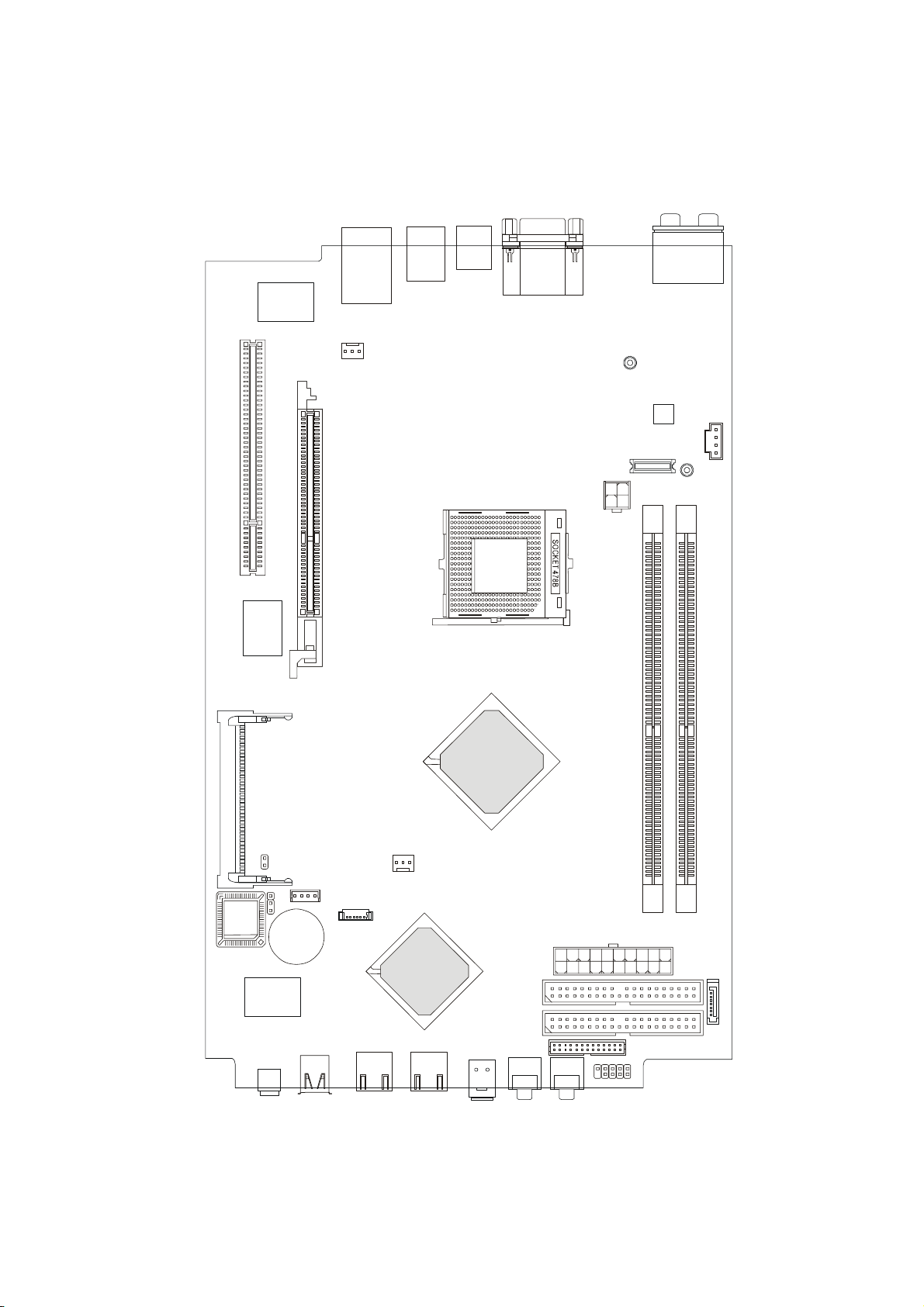
1.1 Mainboard layout
RTL8100C
P
C
I
S
l
o
t
1
A
G
P
S
l
o
t
L
P
C
4
s
7
m
M
s
9
c
9
7
-
N
R
B
o
t
t
o
m
:
U
S
B
p
o
r
t
s
SYSFAN1
T
o
p
:
L
A
N
J
a
c
k
U
S
B
p
o
r
t
s
T
V
-
o
u
t
(
S
)
c
o
n
n
e
c
t
o
r
B
T
o
o
p
t
t
:
o
C
m
O
:
M
V
G
P
A
o
r
P
t
o
r
t
MDCT2000
JPW1
B
M
:
:
S
C
P
S
D
-
O
I
F
u
O
t
u
t
MHT2007
Codec
T
M
B
:
:
:
R
M
L
S
i
i
n
c
-
O
e
-
u
O
t
u
t
MHT2008
T
:
L
i
n
e
-
I
n
C
N
T
2
0
1
1
BIOS
M
I
N
I
P
C
I
1
J1
JCMOS
VIA
VT6307
J1394-1
JUSBT20001
BATT
+
J1394-2
R
R
a
S
A
d
3
T
e
5
I
o
0
n
CPUFAN1
CRT2000
I
S
X
B
A
P
3
T
3
0
I
0
0
0
USBT2003USBT2000
SPDIFIN1
IDE2
IDE1
AUDIO2
MS-7072 Mainboard
AUDIO
ATX
Power Supply
CN16
JFP1
1
DIMM1
DIMM2
SATA1
1-2
Page 6
Mainboard Hardware
1.2 CPU
This mainboard supports Intel® P4 Northwood up to 3.2GHz and Prescott up to
3.4GHz. The mainboard uses a CPU socket called PGA478 for easy CPU installation.
When you are installing the CPU, make sure the CPU has a heat sink and a cooling fan
attached on the top to prevent overheating. Remember to peel off the sticker before
you install the CPU cooler . For information on how to inst all the CPU and cooler, refer
to Quick Installation Guide.
Note:
1. Read the instructions on the cooler before you start the installation.
2. Overheating will seriously damage the CPU and system, always make
sure the cooling fan can work properly to protect the CPU from overheating.
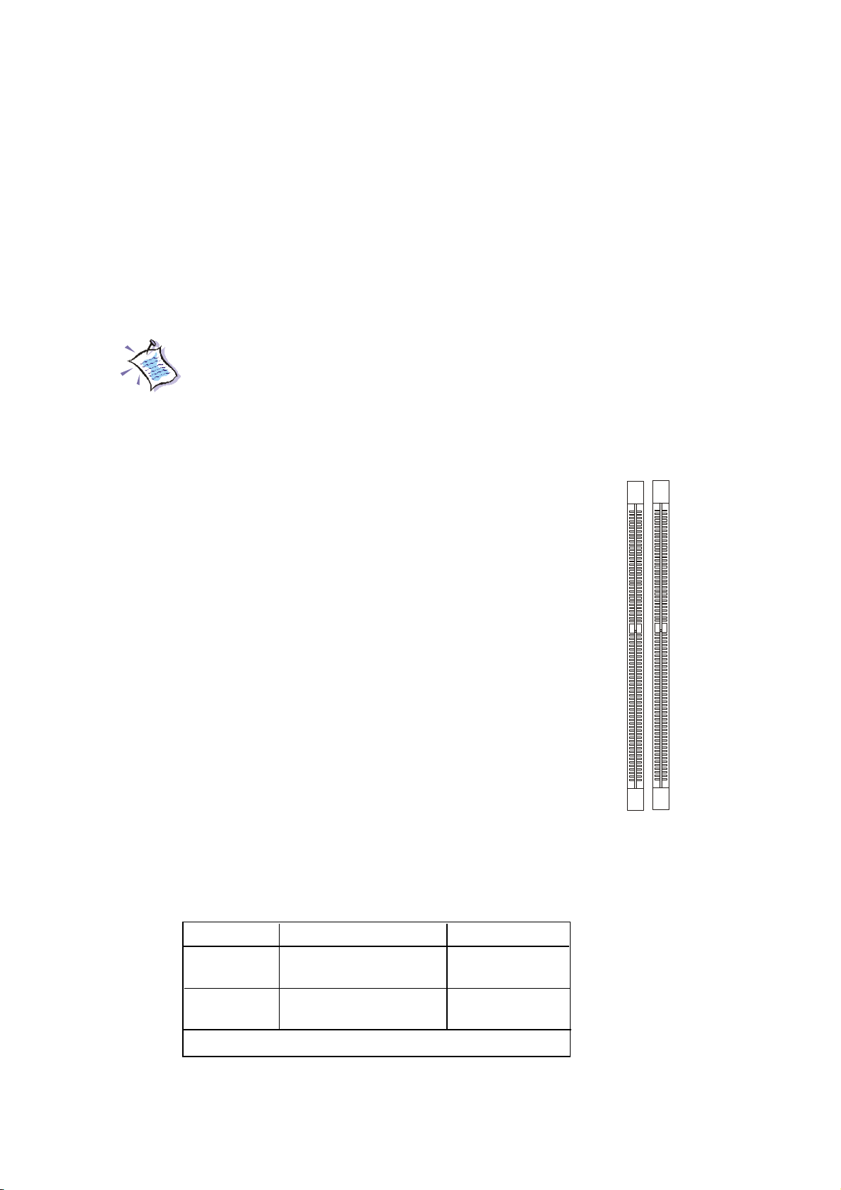
1.3 Memory
The mainboard provides 2 slots for 184-pin DDR SDRAM
DIMM (Double In-Line Memory Module) modules and supports the
memory size up to 2GB. You can install DDR400/DDR333/DDR266
modules into the DDR DIMM slots.
DIMM2
DIMM1
DIMM Module Combination
Install at least one DIMM module on the slots. You can install either single- or
double-sided modules in any order to meet your own needs. Memory modules can be
installed in any combination as follows:
Slot Memory Module T otal Memory
DIMM 1 DDR S/D 64MB~1GB
(Bank 0 & 1)
DIMM 2 DDR S/D 64MB~1GB
(Bank 2 & 3)
Maximum System Memory Supported 64MB~2GB
S: Single Side
D: Double Side
1-3
Page 7
Chapter 1
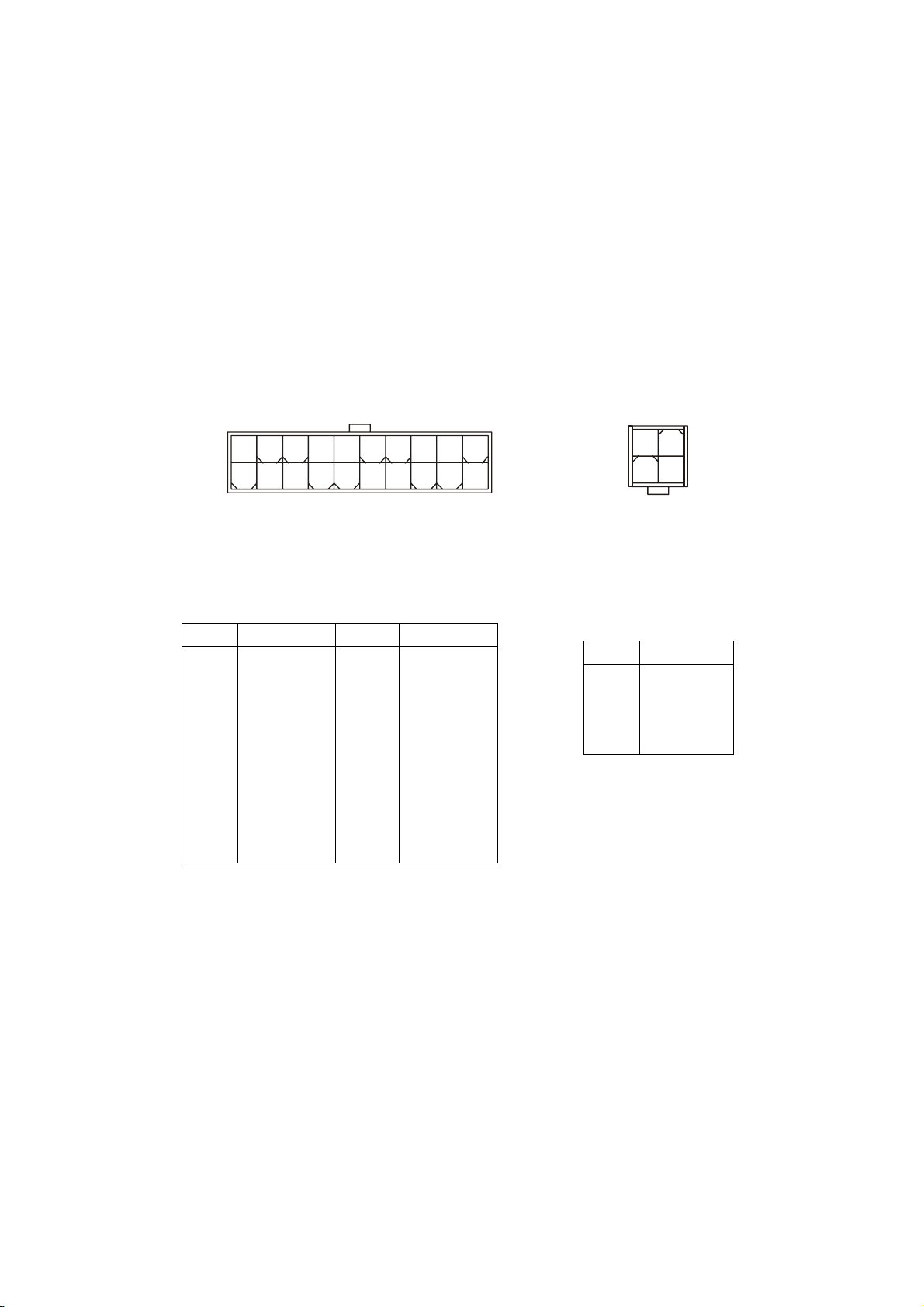
1.4 Power Supply
The system is equipped with a 220W (PFC) ATX power supply. The power
cord of power supply has been connected to the connector ATX1 on the mainboard
when shipped out. Except the 20-pin connector ATX1, you can find another 4-pin
power connector JPW1 on the mainboard.
20
10
ATX1 Pin Definition
PIN SINGAL
1 3.3V
2 3.3V
3 GND
45V
5 GND
65V
7 GND
8 PW_OK
9 5V_SB
10 12V
A TX1
PIN SIGNAL
11 3.3V
12 -12V
13 GND
14 PS_ON
15 GND
16 GND
17 GND
18
19 5V
20 5V
11
1
2
4
1
3
JPW1
JPW1 Pin Definition
PIN SINGAL
1 GND
2 GND
3 12V
4 12V
1-4
Page 8

Mainboard Hardware
1.5 Front panel
The Front Panel is independent and extended from the mainboard. It’s connected to the Front I/O Connector on the mainboard. You can find the following ports
on the Front Panel.
J1394-1
J1394-2
USB x 2
Optical SPDIF-In
Mic-InHead-Phone
IEEE 1394 Port: J1394-2
The mainboard provides two IEEE 1394 ports. This smaller one is designed
for you to connect the IEEE 1394 device with external power. The IEEE 1394 highspeed serial bus complements USB by providing enhanced PC connectivity for a
wide range of devices, including consumer electronics audio/video (A/V) appliances,
storage peripherals, other PCs, and portable devices.
Software Support
IEEE 1394 Driver is provided by Windows® 98 SE, Windows® XP, Windows® ME and Windows® 2000. Just plug in the IEEE 1394 connector into
the port. These Operating Systems will install the driver for IEEE 1394.
IEEE 1394 Port: J1394-1
The bigger 6-pin IEEE 1394 Port on the front panel is designed for you to
connect to IEEE 1394 devices without external power. That means the mainboard can
provide the power for the devices connected to this port.
1-5
Page 9
Chapter 1
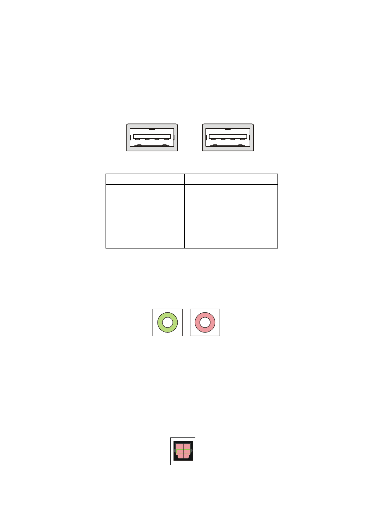
USB Ports
The mainboard provides a UHCI (Universal Host Controller Interface) Universal Serial Bus root for attaching USB devices such as keyboard, mouse or other
USB-compatible devices. You can plug the USB device directly into the connector.
USB Port Description
PIN SIGNAL DESCRIPTION
1 VCC +5V
2 -Data 0 Negative Data Channel 0
3 +Data 0 Positive Data Channel 0
4 GND Ground
5 VCC +5V
6 -Data 1 Negative Data Channel 1
7 +Data 1 Positive Data Channel 1
8 GND Ground
Mic-in/Head-Phone
Mic-in is a connector for stereo microphone. Head-Phone is a connector for
Speakers or Headphones.
OPTICAL SPDIF-in
The OPTICAL connector allows you to receive the audio file of SPDIF interface for recording and playing.
The SPDIF (Sony & Philips Digital Interface) is developed jointly by the Sony
and Philips corporations. A standard audio file transfer format, SPDIF allows the
transfer of digital audio signals from one device to another without having to be
converted first to an analog format.
1-6
Page 10
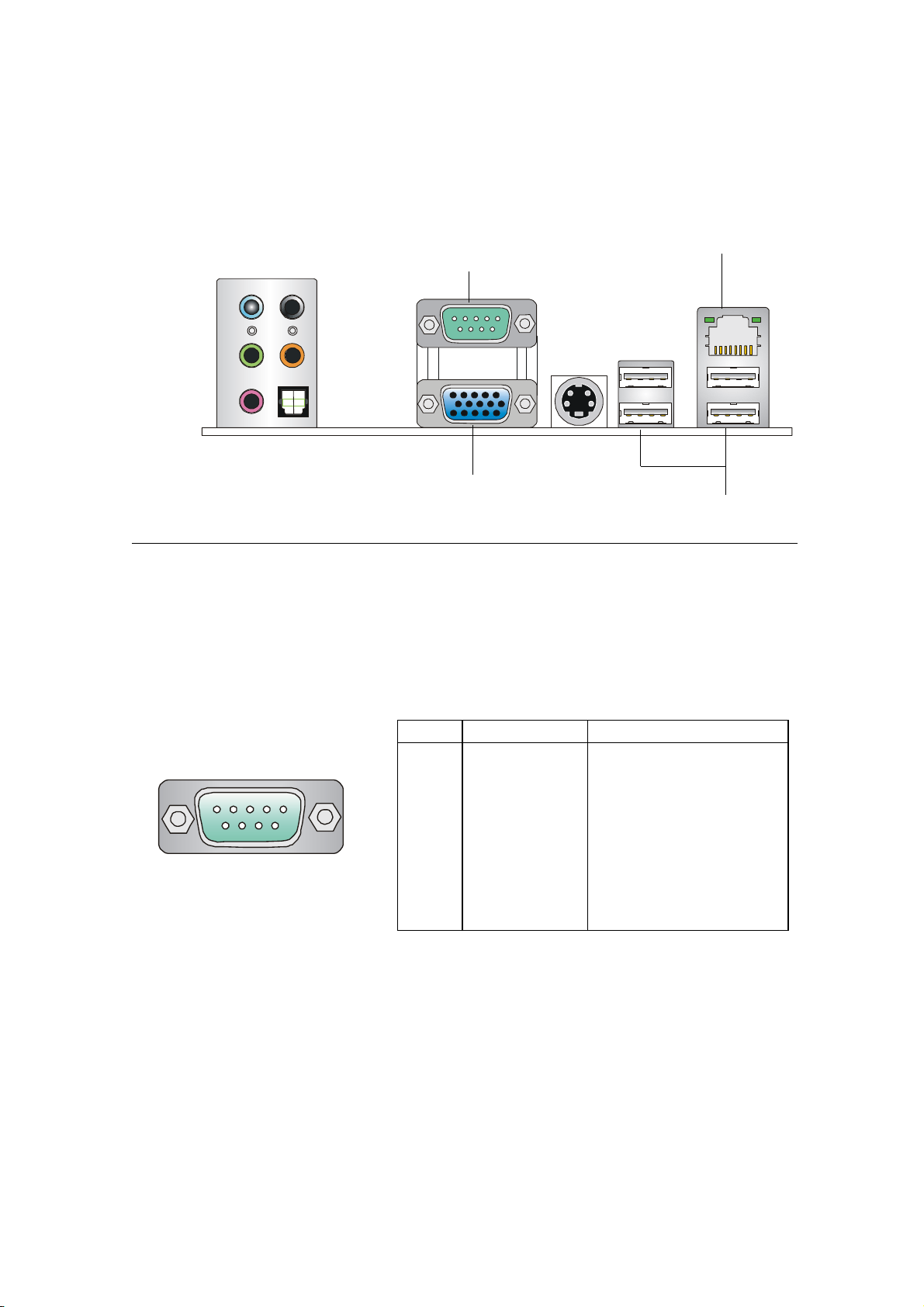
1.6 Back panel
The Back Panel provides the following ports:
RS-Out
Line-In
Line-Out
Mic-in
CS-Out
SPDIF-Out
(optical)
Mainboard Hardware
LAN Port
Serial Port
VGA Port
USB
Serial Port
The mainboard offers a 9-pin male DIN serial port. The port is 16550A high
speed communication ports that sends/receives 16 bytes FIFOs. You can attach a
serial mouse or other serial devices directly to the connector.
Pin Definition
PIN SIGNAL DESCRIPTION
1 2 3 4 5
6 7 8 9
9-Pin Male DIN Connector
1 DCD Data Carry Detect
2 SIN Serial In or Receive Data
3 SOUT Serial Out or Transmit Data
4 DTR Data T erminal Ready
5 GND Ground
6 DSR Data Set Ready
7 RTS Request To Send
8 CTS Clear T o Send
9 RI Ring Indicate
1-7
Page 11
Chapter 1
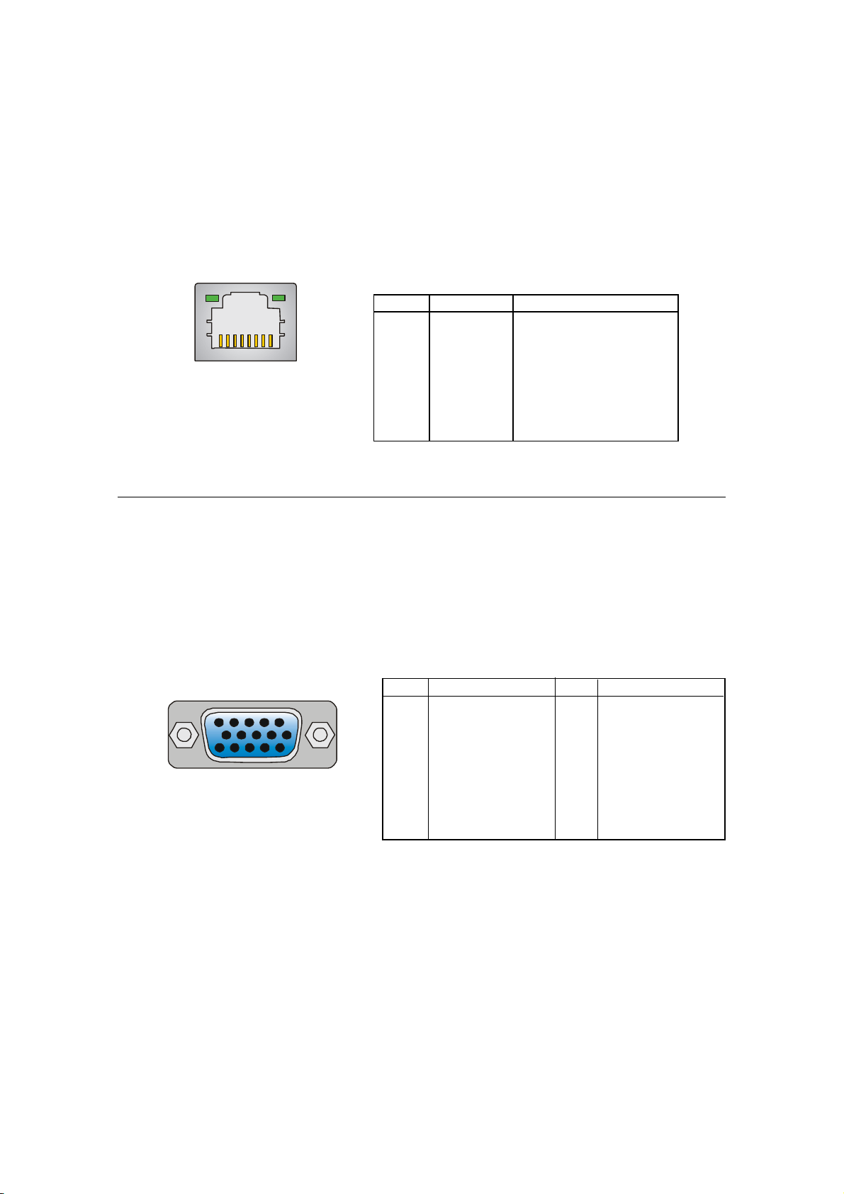
RJ45 LAN Jack
The mainboard provides one standard RJ-45 jack for connection to Local Area Network (LAN). You can connect a network cable to the LAN jack.
Pin Definition
PIN SIGNAL DESCRIPTION
1 TDP Transmit Differential Pair
2 TDN Transmit Differential Pair
3 RDP Receive Differential Pair
4 NC Not Used
5 NC Not Used
6 RDN Receive Differential Pair
7 NC Not Used
8 NC Not Used
VGA Port
The mainboard provides one DB 15-pin female connector to connect a VGA
monitor.
5 1
15 11
DB 15-Pin Female Connector
Pin Signal Description Pin Signal Description
1 RED 2 GREEN
3 BLUE 4 N/C
5 GND 6 GND
7 GND 8 GND
9 +5V 10 GND
1 1 N/C 1 2 SDA
13 Horizontal Sync 14 Vertical Sync
15 SCL
1-8
Page 12
Mainboard Hardware
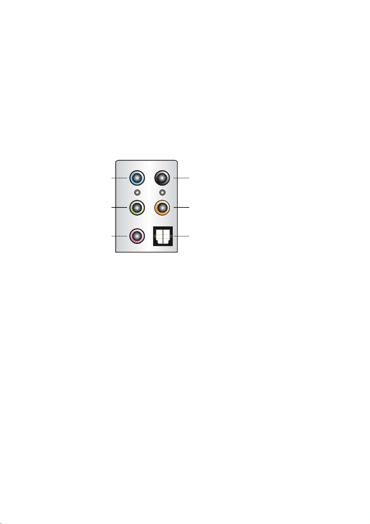
Audio Port Connectors
The left 3 audio jacks are for 2-channel mode for stereo speaker output: Line Out is
a connector for Speakers or Headphones. Line In is used for external CD player,
Tape player, or other audio devices. Mic is a connector for stereo microphone.
However, there is an advanced audio application provided by CMI9761A to offer
support for 5.1-channel audio operation and can turn rear audio connectors from
2-channel to 4-/5.1-channel audio.
Line In
Line Out
MIC
Rear Speaker Out
(in 5.1CH)
Center/Subwoofer Speaker Out
( in 5.1CH)
S/PDIF Out-Optical
1-9
Page 13
Chapter 1
1.7 Connectors
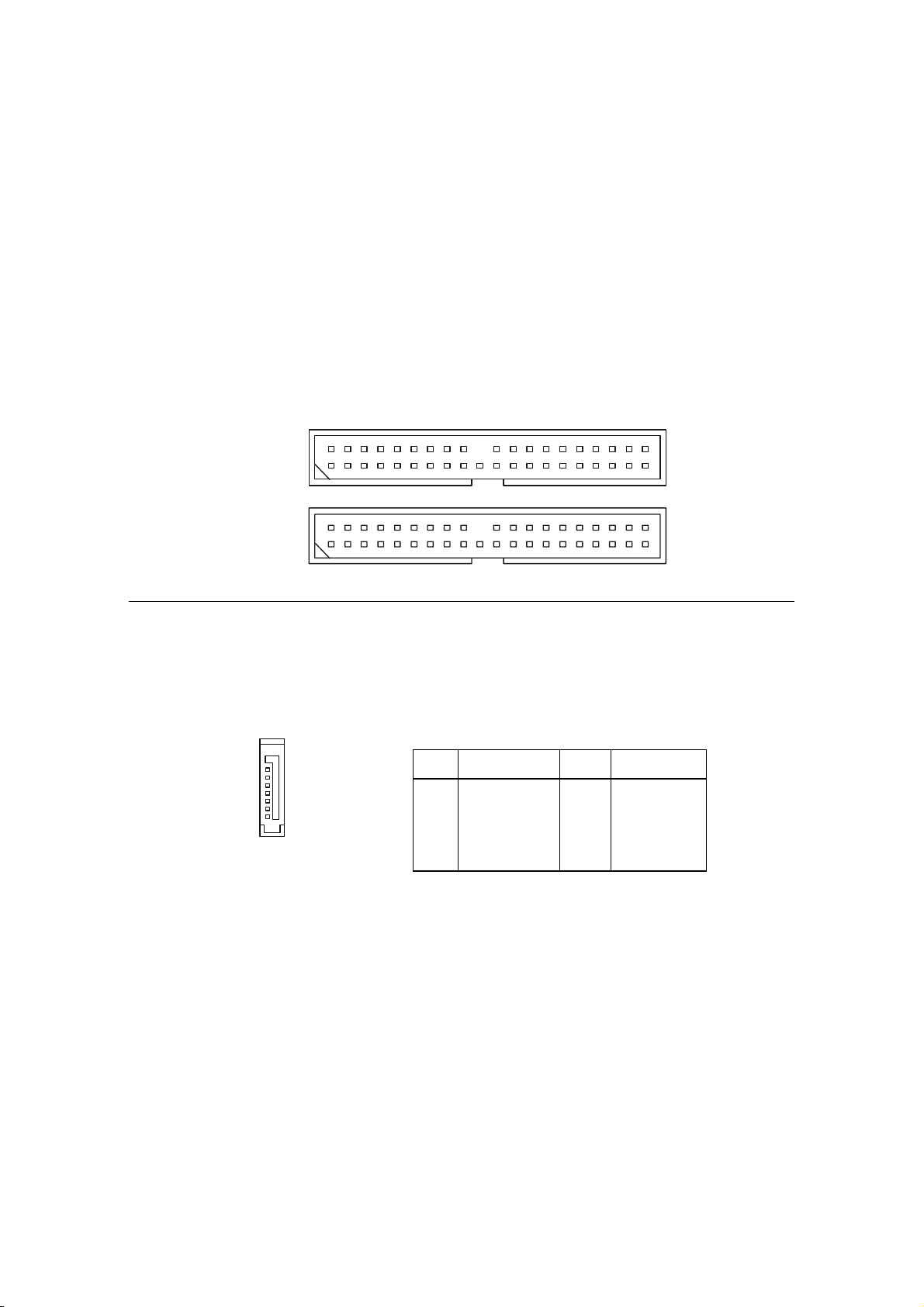
IDE Connectors: IDE1 & IDE2
The mainboard has a 32-bit Enhanced PCI IDE and Ultra DMA 33/66/100 controller that provides PIO mode 0~4, Bus Master, and Ultra DMA/33/66/100 function.
The two connectors on the mainboard allows you to connect to two IDE devices.
IDE1 (Primary IDE Connector) - IDE1 can only connect a HDD.
IDE2 (Secondary IDE Connector) - IDE2 can only connect a CD-ROM drive.
IDE2
IDE1
Serial AT A Connector: SA T A1
The mainboard provides the connector to connect the hard disk of Serial ATA
interface.
Pi n Signal Pin Signal
1 GND TXP
3 TXN GND
5 RXN RXP
7 GND
SATA1
Pin Definition
2
4
6
1-10
Page 14

Mainboard Hardware
Card Reader Connector: CRT2000
The mainboard provides a connector to connect the USB Card Reader (for
Deluxe Model) on the Front Panel.
CRT2000
Modem Module Connector: MDCT2000 (Optional)
The mainboard provides the connector to connect the modem module. The
modem module is directly inserted into the connector without an extra cable.
MDCT2000
CPU Fan Connectors: CPUFAN1/SYSFAN1
The CPUFan1/SYSFAN1 connectors support system cooling fans with +12V
that is controlled by PWM. When connecting the wire to the three-pin head connectors,
always note that the red wire is the positive and should be connected to the +12V
(that is controlled by PWM), the black wire is Ground and should be connected to
GND.
GND
FAN Power
CPUFAN1
SENSOR
SENSOR
FAN Power
GND
SYSF AN1
1-11
Page 15

Chapter 1
TV-Tuner Card Connector: CNT2011
The mainboard provides the connector to connect the TV-Tuner card. You
can insert the TV-Tuner card into the PCI Slot 1.
L
GND
R
CNT201 1
Color LED Connector: LCMT2000
The connector is used to connect the color LED on the front panel.
2
1
Pin Definition
Pin Signal
1 SRS
5 MP_RTS
7 MP_DTR
9 IR or RST#
11 CD_SMI#
13 VCC5
15 MP_CTR_PWRON
17 IDE_LED
19 PLED1
21 PLED2
25 BASS_DETECT
Pin Signal
4 OS-SEL
6 MP_RXD
8 MP_TXD
10 FLAT
12 ROCK
14 POPS
16 CLASSIC
18 EQ_CYC
20 VCC5-SB
23 BASS
26
LCMT2000
25
1-12
Page 16

Mainboard Hardware
1.8 Jumper
There is a CMOS RAM on board that has a power supply from external
battery to keep the data of system configuration. With the CMOS RAM, the system
can automatically boot OS every time it is turned on. That battery has long life time for
at least 2 years. If you want to clear the system configuration, use the JBAT1 (Clear
CMOS Jumper ) to clear data. Follow the instructions below to clear the data:
Clear CMOS Jumper: JBAT1
1
3
1
3
JBA T1
Keep Data
You can clear CMOS by shorting 2-3 pin while the system is off. Then
return to 1-2 pin position. Avoid clearing the CMOS while the system is
on; it will damage the mainboard.
Clear Data
1-13
Page 17

Chapter 1
1.9 Slots
PCI Slot
The PCI slot allows you to insert PCI card or TV Tuner card. When adding or
removing expansion cards, make sure that you unplug the power supply first.
Meanwhile, read the documentation for the expansion card to make any necessary
hardware or software settings.
AGP (Accelerated Graphics Port) Slot
The AGP slot allows you to insert the AGP graphics card. AGP is an interface
specification designed for the throughput demands of 3D graphics. It introduces a
66MHz, 32-bit channel for the graphics controller to directly access main memory and
provides 4x/8x throughputs.
Mini PCI Slot
The motherboard provides a mini PCI slot for connecting a mini PCI interface
card.
AGPPCI
Mini PCI
1-14
Page 18

Setting BIOS FunctionSetting BIOS Function
Setting BIOS Function
Setting BIOS FunctionSetting BIOS Function
2.1 Entering Setup2.1 Entering Setup
2.1 Entering Setup
2.1 Entering Setup2.1 Entering Setup
2.2 The Main Menu2.2 The Main Menu
2.2 The Main Menu
2.2 The Main Menu2.2 The Main Menu
2.3 Standard CMOS Features2.3 Standard CMOS Features
2.3 Standard CMOS Features
2.3 Standard CMOS Features2.3 Standard CMOS Features
2.4 Advanced BIOS Features2.4 Advanced BIOS Features
2.4 Advanced BIOS Features
2.4 Advanced BIOS Features2.4 Advanced BIOS Features
2.5 Advanced Chipset Features2.5 Advanced Chipset Features
2.5 Advanced Chipset Features
2.5 Advanced Chipset Features2.5 Advanced Chipset Features
2.6 Integrated Peripherals2.6 Integrated Peripherals
2.6 Integrated Peripherals
2.6 Integrated Peripherals2.6 Integrated Peripherals
2.7 Power Management Setup2.7 Power Management Setup
2.7 Power Management Setup
2.7 Power Management Setup2.7 Power Management Setup
2.8 PnP/PCI Configurations2.8 PnP/PCI Configurations
2.8 PnP/PCI Configurations
2.8 PnP/PCI Configurations2.8 PnP/PCI Configurations
2.9 PC Health Status2.9 PC Health Status
2.9 PC Health Status
2.9 PC Health Status2.9 PC Health Status
2.10 Load Fail-Safe/Optimized Defaults2.10 Load Fail-Safe/Optimized Defaults
2.10 Load Fail-Safe/Optimized Defaults
2.10 Load Fail-Safe/Optimized Defaults2.10 Load Fail-Safe/Optimized Defaults
2.11 Set Supervisor/User Password2.11 Set Supervisor/User Password
2.11 Set Supervisor/User Password
2.11 Set Supervisor/User Password2.11 Set Supervisor/User Password
Page 19

Chapter 2
2.1 Entering Setup
Power on the computer and the system will start POST (Power On
Self Test) process. When the message below appears on the screen, press
<DEL> key to enter Setup.
Press DEL to enter SETUP
If the message disappears before you respond and you still wish to
enter Setup, restart the system by turning it OFF and On or pressing the
RESET button. You may also restart the system by simultaneously press-
ing <Ctrl>, <Alt>, and <Delete> keys.
Control Keys
<↑> Move to the previous item
<↓> Move to the next item
<←> Move to the item in the left hand
<→> Move to the item in the right hand
<Enter> Select the item
<Esc> Jumps to the Exit menu or returns to the main
menu from a
<-/PD> Decrease the numeric value or make changes
<+/PU> Increase the numeric value or make changes
<F7> Load Fail-Safe Defaults
<F6> Load Optimal Defaults
<F10> Save all the CMOS changes and exit
submenu
2-2
Page 20

Setting BIOS Function
Getting Help
After entering the Setup menu, the first menu you will see is the
Main Menu.
Main Menu
The main menu lists the setup functions you can make changes
to. You can use the control keys ( ↑↓ ) to select the item. The on-line
description of the highlighted setup function is displayed at the bottom
of the screen.
Sub-Menu
If you find a right pointer symbol (as
shown in the right view) appears to
the left of certain fields that means a
sub-menu containing additional op-
tions can be launched from this field.
You can use control keys (↑↓ ) to
highlight the field and press <Enter>
to call up the sub-menu. Then you can
use the control keys to enter values and move from field to field within
a sub-menu. If you want to return to the main menu, just press <Esc >.
8IDE Primary Master
8IDE Primary Slave
8IDE Secondary Master
8IDE Secondary Slave
General Help <F1>
The BIOS setup program provides a General Help screen. You
can call up this screen from any menu by simply pressing <F1>. The
Help screen lists the appropriate keys to use and the possible selections
for the highlighted item. Press <Esc> to exit the Help screen.
2-3
Page 21

Chapter 2
2.2 The Main Menu
Once you enter Phoenix-Award® BIOS CMOS Setup Utility, the
Main Menu (Figure 1) will appear on the screen. The Main Menu allows
you to select from eleven setup functions and two exit choices. Use
arrow keys to select among the items and press <Enter> to accept or
enter the sub-menu.
Standard CMOS Features
Use this menu for basic system configurations, such as time, date etc.
Advanced BIOS Features
Use this menu to setup the items of AWARD
Advanced Chipset Features
Use this menu to change the values in the chipset registers and optimize
your system’s performance.
Integrated Peripherals
Use this menu to specify your settings for integrated peripherals.
®
special enhanced features.
2-4
Page 22

Setting BIOS Function
Power Management Setup
Use this menu to specify your settings for power management.
PnP/PCI Configurations
This entry appears if your system supports PnP/PCI.
PC Health Status
This entry shows your PC health status.
Load Fail-Safe Defaults
Use this menu to load the default values set by the BIOS vendor for
stable system performance.
Load Optimized Defaults
Use this menu to load the default values set by the mainboard manufacturer specifically for optimal performance of the mainboard.
Set Supervisor Password
Use this menu to set Supervisor Password.
Set User Password
Use this menu to set User Password.
Save & Exit Setup
Save changes to CMOS and exit setup.
Exit Without Saving
Abandon all changes and exit setup.
2-5
Page 23

Chapter 2
2.3 Standard CMOS Features
The items in Standard CMOS Features Menu are divided into 8
categories. Each category includes no, one or more than one setup
items. Use the arrow keys to highlight the item and then use the <PgUp>
or <PgDn> keys to select the value you want in each item.
Date
This allows you to set the system to the date that you want (usually the
current date). The format is <day><month> <date> <year>.
Time
This allows you to set the system time that you want (usually the current
time). The time format is <hour> <minute> <second>.
IDE Primary/Secondary Master/Slave
Press PgUp/<+> or PgDn/<-> to select [Manual], [None] or [Auto] type.
Note that the specifications of your drive must match with the drive
table. The hard disk will not work properly if you enter improper infor-
mation for this category. If your hard disk drive type is not matched or
listed, you can use [Manual] to define your own drive type manually.
2-6
Page 24

Setting BIOS Function
If you select [Manual], related information is asked to be entered to the
following items. Enter the information directly from the keyboard. This
information should be provided in the documentation from your hard
disk vendor or the system manufacturer.
Access Mode The settings are CHS, LBA, Large, Auto.
Capacity The formatted size of the storage device.
Cylinder Number of cylinders.
Head Number of heads.
Precomp Write precompensation.
Landing Zone Cylinder location of the landing zone.
Sector Number of sectors.
Halt On
The setting determines whether the system will stop if an error is de-
tected at boot. Available options are:
[All Errors] The system stops when any error is detected.
[No Errors] The system doesn’t stop for any detected error.
[All, But Keyboard] The system doesn’t stop for a keyboard error.
[All, But Diskette] The system doesn’t stop for a disk error.
[All, But Disk/Key] The system doesn’t stop for either a disk or a
keyboard error.
System Information (read only)
Press <Enter> to enter the sub-menu and the following screen appears:
2-7
Page 25

Chapter 2
2.4 Advanced BIOS Features
Quick Booting
Setting the item to [Enabled] allows the system to skip certain tests while
booting. This will decrease the time needed to boot the system. Available options: [Enabled], [Disabled].
Security Option
This specifies the type of BIOS password protection that is implemented.
Settings are described below:
DescriptionOption
[Setup]
[Always]
Boot Up Num-Lock LED
This setting is to set the Num Lock status when the system is powered
on. Setting to [On] will turn on the Num Lock key when the system is
powered on. Setting to [Off] will allow users to use the arrow keys on
the numeric keypad. Setting options: [On], [Off].
The password prompt appears only when end users try
to run Setup.
A password prompt appears every time when the computer
is powered on or when end users try to run Setup.
2-8
Page 26

Setting BIOS Function
Full Screen LOGO Display
This item enables you to show the company logo on the bootup screen.
Settings are:
[Enabled] Shows a still image (logo) on the full screen at boot.
[Disabled] Shows the POST messages at boot.
Hyper-Threading Technology
The processor uses Hyper-Threading technology to increase transaction
rates and reduces end-user response times. The technology treats the
two cores inside the processor as two logical processors that can ex-
ecute instructions simultaneously. In this way, the system performance
is highly improved. If you disable the function, the processor will use
only one core to execute the instructions. Settings: [Enabled], [Disabled].
Optical Drive AAM
Optical Drive Auto Acoustic Management (AAM) allows you to
reduce the optical drive noise. Selecting [Silent] will minimize the
drive performance and have the lowest noise. [Medium] is default
setting while [Disable] will have the maximum drive performance.
Hard Drive AAM
Hard Drive Auto Acoustic Management (AAM) allows you to reduce
the hard drive noise. Selecting [Silent] will minimize the drive
performance and have the lowest noise. [Medium] is default setting
while [Disable] will have the maximum drive performance.
2-9
Page 27

Chapter 2
Boot Sequence
Press <Enter> to enter the sub-menu. Then you may use the arrow keys
to select the desired device, then press <+>, <-> or <PageUp>,
<PageDown> key to move it up/down in this hard disk boot priority
list.
1st/2nd/3rd Boot Device
The items allow you to set the sequence of boot devices where
BIOS attempts to load the disk operating system.
2-10
Page 28

Setting BIOS Function
2.5 Advanced Chipset Features
*
* Dual channel Interleave [system optimal]
NOTE: Change these settings only if you are familiar with the chipset.
Current FSB/DRAM Frequency
It shows the current clock frequency of the front side bus/memory. (read
only)
Memory Frequency For
Use this item to configure the clock frequency of the installed DRAMs.
Setting options: [By SPD], [1:1], [DDR-200], [DDR-266], [DDR-333], [DDR-
400].
Current CAS Latency
This controls the timing delay (in clock cycles) before SDRAM starts a
read command after receiving it. (read only)
Current TRCD
When DRAM is refreshed, both rows and columns are addressed
2-11
Page 29

Chapter 2
separately. This setup item allows you to determine the timing of the
transition from RAS (row address strobe) to CAS (column address strobe).
The less the clock cycles, the faster the DRAM performance. (read only)
Current TRP
This setting controls the number of cycles for Row Address Strobe (RAS)
to be allowed to precharge. If insufficient time is allowed for the RAS to
accumulate its charge before DRAM refresh, refresh may be incomplete
and DRAM may fail to retain data. This item applies only when synchro-
nous DRAM is installed in the system. (read only)
Current TRAS
This setting determines the time RAS takes to read from and write to a
memory cell. (read only)
DRAM Timing
Selects whether DRAM timing is controlled by the SPD (Serial Presence
Detect) EEPROM on the DRAM module. Setting to [By SPD] enables
DRAM timings to be determined by BIOS based on the configurations on
the SPD. Selecting [Manual] allows users to configure the DRAM tim-
ings manually.
CAS Latency
This controls the timing delay (in clock cycles) before SDRAM starts a
read command after receiving it. Settings: [2], [2.5], [3] (clocks). [2]
(clocks) increases the system performance the most while [3] (clocks)
provides the most stable performance.
TRCD
When DRAM is refreshed, both rows and columns are addressed
separately. This setup item allows you to determine the timing of the
2-12
Page 30

Setting BIOS Function
transition from RAS (row address strobe) to CAS (column address strobe).
The less the clock cycles, the faster the DRAM performance. Settings:
[2T] to [5T].
TRP
This setting controls the number of cycles for Row Address Strobe (RAS)
to be allowed to precharge. If insufficient time is allowed for the RAS to
accumulate its charge before DRAM refresh, refresh may be incomplete
and DRAM may fail to retain data. This item applies only when synchro-
nous DRAM is installed in the system. Setting options: [2T] to [5T].
TRAS
This setting determines the time RAS takes to read from and write to a
memory cell. Setting options: [4T] to [9T].
Dual channel Interleave
Setting options: [system optional] and [graphics optional].
AGP Aperture Size (MB)
This setting controls just how much system RAM can be allocated to
AGP for video purposes. The aperture is a portion of the PCI memory
address range dedicated to graphics memory address space. Host cycles
that hit the aperture range are forwarded to the AGP without any
translation. The option allows the selection of an aperture size of [32MB],
[64MB], [128MB], [256MB], [512MB], [1GB], and [2GB].
Onboard VGA Frame Buffer
Frame Buffer is the video memory that stores data for video display
(frame). This field is used to determine the memory size for Frame
Buffer. Larger frame buffer size increases video performance. Settings:
[8M], [16M], [32M], [64MB], [128MB].
2-13
Page 31

Chapter 2
Video Display Device
Use the field to select the type of device you want to use as the
display(s) of the system. Setting options: [Auto], [CRT only], [CLD
only], [DFP only], [TV only], [CRT Force, Other Auto], [TV Force,
Other Auto], [CRT Force, TV Force].
TV Standard
Select the TV standard which is used as the video signal format of your
TV if you have connected a TV to the system. These TV standards are
available for the field: [NTSC], [PAL], [PAL-M], [PAL-60], [PAL-JAP],
[PAL-CN}, [PAL-N], [SCART_RGB] .
2-14
Page 32

2.6 Integrated Peripherals
Setting BIOS Function
USB Controller
This setting is used to enable/disable the onboard USB controller. Set-
ting options: [Disabled], [Enabled].
USB 2.0 Controller
This setting is used to enable/disable the onboard USB2.0 controller.
This setting works only when the operating system installed supports
USB2.0 driver, such as Windows 2000/XP/ME. Setting options: [Disabled],
[Enabled].
USB Mouse Support
Select [Enabled] if you need to use a USB mouse in the operating system
that does not support or have any USB mouse driver installed, such as
DOS and SCO Unix. Setting options: [Enabled], [Disabled].
USB Legacy Support
Set to [All Device] if your need to use any USB device in the operating
system that does not support or have any USB driver installed, such as
2-15
Page 33

Chapter 2
DOS and SCO Unix. Set to [No Mice] only if you want to use any USB
device other than the USB mouse. Setting options: [Disabled], [All
Device], [No Mice].
AC97 Controller
[Auto] allows the mainboard to detect whether an audio device is used.
If an audio device is detected, the onboard AC’97 audio controller will
be enabled; if not, it is disabled. Disable the controller if you want to
use other controller cards to connect an audio device. Settings: [Auto],
[Disabled].
RealTek LAN Controller
This setting controls the onboard LAN device. Setting options: [Disabled],
[Enabled].
TealTek LAN Boot ROM
This item is used to decide whether to invoke the Boot ROM of the
Onboard LAN Chip. Settings: [Enabled], [Disabled].
IDE Devices Configuration
Press <Enter> to enter the sub-menu and the following screen appears:
2-16
Page 34

Setting BIOS Function
PCI IDE BusMaster
Set this option to [Enabled] to specify that the IDE controller on the PCI
local bus has bus mastering capability. Settings options: [Disabled],
[Enabled].
OnChip IDE Channel 0/1
The chipset contains a PCI IDE interface with support for two IDE channels.
Select [Enabled] to activate the IDE interface. Select [Disabled] to de-
activate this interface.
IDE HDD Block Mode
Block mode is also called block transfer, multiple commands, or mul-
tiple sector read/write. If your IDE hard drive supports block mode (most
new drives do), select [Enabled] for automatic detection of the optimal
number of block read/writes per sector the drive can support. Settings:
[Enabled], [Disabled].
SATA Devices Configuration
Press <Enter> to enter the sub-menu and the following screen appears:
2-17
Page 35

Chapter 2
Onboard Chip SATA
This setting is used to specify the S-ATA IDE interface. The settings are:
[Disabled] Disable the S-ATA controller.
[Enalbed] Enable the S-ATA controller.
SATA ROM Control
This setting is used to specify the S-ATA HDD function. The settings
are:
[Disabled] Disable the SATA HDD function.
[Enalbed] Enable the S-ATA HDD function.
I/O Devices Configuration
Press <Enter> to enter the sub-menu and the following screen appears:
COM Port 1/2
These items specify the base I/O port address and IRQ for the onboard
Serial Port 1/2. Selecting [Auto] allows BIOS to automatically deter-
mine the correct base I/O port address. Settings: [Disabled], [3F8/IRQ4],
[2F8/IRQ3], [3E8/IRQ4], [2E8/IRQ3], [Auto].
2-18
Page 36

Setting BIOS Function
2.7 Power Management Setup
ACPI Standby State
This item specifies the power saving mode for ACPI function. If your
operating system supports ACPI, such as Windows 98SE, Windows ME
and Windows 2000, you can choose to enter the Standby mode in S1(POS)
or S3(STR) fashion through the setting of this field. Options are:
[S1(POS)] The S1 sleep mode is a low power state. In this
state, no system context (CPU or chipset) is lost and
hardware main tains all system context.
[S3(STR)] The S3 sleep mode is a power-down state in which
power is supplied only to essential components such
as main memory and wake-capable devices and all
system context is saved to main memory. The infor
mation stored in memory will beused to restore the
PC to the previous state when an “wake up” event
occurs.
[Auto] BIOS determines the mode automatically.
2-19
Page 37

Chapter 2
Power Button Function
This feature sets the function of the power button. Settings are:
[Power Off] The power button functions as normal power off
button.
[Suspend] When you press the power button, the computer
enters the suspend/sleep mode, but if the button is
pressed for more than four seconds, the computer is
turned off.
USB Resume From S3
This item allows the USB device to wake up the system from S3 sleep
state. Settings: [Enabled], [Disabled].
Resume By RTC Alarm
The field is used to enable or disable the feature of booting up the sys-
tem on a scheduled time/date.
Date (of Month)
The field specifies the date for Resume By RTC Alarm.
Settings: [0]~[31].
Resume Time(hh:mm:ss)
The field specifies the time for Resume By RTC Alarm.
Format is <hour><minute><second>.
2-20
Page 38

Setting BIOS Function
2.8 PnP/PCI Configurations
This section describes configuring the PCI bus system and PnP
(Plug & Play) feature. PCI, or Peripheral Component Interconnect, is a
system which allows I/O devices to operate at speeds nearing the speed
the CPU itself uses when communicating with its special components.
This section covers some very technical items and it is strongly recom-
mended that only experienced users should make any changes to the
default settings.
Clear ESCD
Normally, you leave this field [Disabled]. Select [Enabled] to reset Ex-
tended System Configuration Data (ESCD) when you exit Setup if you
have installed a new add-on and the system reconfiguration has caused
such a serious conflict that the operating system cannot boot.
Primary Graphic Adaptor
This setting specifies which VGA card is your primary graphics adapter.
Setting options are:
2-21
Page 39

Chapter 2
[AGP] The system initializes the installed AGP card
[PCI Slot] The system initialize the installed PCI VGA
first. If the AGP card is not available, it will
initialize the PCI VGA card.
card first. If the PCI VGA card is not
available, it will initialize the AGP card.
2-22
Page 40

2.9 PC Health Status
Setting BIOS Function
Shutdown Temperature
If the CPU temperature reaches the limit preset in this setting, the system will shotdown automatically.
Spread Spectrum
When the motherboard’s clock generator pulses, the extreme values
(spikes) of the pulses creates EMI (Electromagnetic Interference). The
Spread Spectrum function reduces the EMI generated by modulating the
pulses so that the spikes of the pulses are reduced to flatter curves.
Note:
1. If you do not have any EMI problem, leave the setting at
[Disabled] for optimal system stability and performance. But
if you are plagued by EMI, select the value of Spread Spectrum for EMI reduction.
2. The greater the Spread Spectrum value is, the greater the
EMI is reduced, and the system will become less stable. For
the most suitable Spread Spectrum value, please consult your
local EMI regulation.
3. Remember to disable Spread Spectrum if you are overclocking
because even a slight jitter can introduce a temporary boost
in clock speed which may just cause your overclocked processor to lock up.
2-23
Page 41

Chapter 2
CPU Clock Ratio
This setting controls the multiplier that is used to determine the internal
clock speed of the processor relative to the external or motherboard
clock speed.
CPU/System Temperature, CPU/System FAN Speed, Vcore, Vccp,
+3.3V, +5V, +12V, HVcc
These items display the current status of all of the monitored hardware
devices/components such as CPU voltages, temperatures and all fans’
speeds.
2-24
Page 42

Setting BIOS Function
2.10 Load Fail-Safe/Optimized Defaults
The two options on the main menu allow users to restore all of the BIOS
settings to the default Fail-Safe or Optimized values. The Optimized
Defaults are the default values set by the mainboard manufacturer
specifically for optimal performance of the mainboard. The Fail-Safe
Defaults are the default values set by the BIOS vendor for stable system
performance.
When you select Load Fail-Safe Defaults, a message as below
appears:
Pressing [Y] loads the BIOS default values for the most stable, minimal
system performance.
When you select Load Optimized Defaults, a message as below
appears:
Pressing [Y] loads the default factory settings for optimal system
performance.
2-25
Page 43

Chapter 2
2.11 Set Supervisor/User Password
When you select this function, a message as below will appear on
the screen:
Type the password, up to six characters in length, and press <En-
ter>. The password typed now will replace any previously set password
from CMOS memory. You will be prompted to confirm the password.
Retype the password and press <Enter>. You may also press <Esc> to
abort the selection and not enter a password.
To clear a set password, just press <Enter> when you are prompted
to enter the password. A message will show up confirming the password
will be disabled. Once the password is disabled, the system will boot
and you can enter Setup without entering any password.
When a password has been set, you will be prompted to enter it
every time you try to enter Setup. This prevents an unauthorized person
from changing any part of your system configuration.
Additionally, when a password is enabled, you can also have Award
BIOS to request a password each time the system is booted. This would
prevent unauthorized use of your computer. The setting to determine
when the password prompt is required is the Security Option of the
ADVANCED BIOS FEATURES menu. If the Security Option is set to
[Always], the password is required both at boot and at entry to Setup. If
set to [Setup], password prompt only occurs when you try to enter Setup.
2-26
About Supervisor Password & User Password:
Supervisor password: Can enter and change the settings of
the setup menu.
User password: Can only enter but do not have the right
to change the settings of the setup
menu.
 Loading...