

MSI MS-6844, AP54G User Manual

i
User’s Guide
MSI AP54G (MS-6844)
Wireless 11g Access Point

ii
FCC Caution
1. The device complies with Part 15 of the FCC rules. Operation is subject to
the following two conditions:
(1) This device may not cause harmful interference, and
(2) This device must accept any interference received, including interference
that may cause undesired operation.
2. FCC RF Radiation Exposure Statement: The equipment complies with FCC
RF radiation exposure limits set forth for an uncontrolled environment.
This equipment should be installed and operated with a minimum
distance of 20 centimeters between the radiator and your body.
3. This Transmitter must not be co-located or operating in conjunction with
any other antenna or transmitter.
4. Changes or modifications to this unit not expressly approved by the
party responsible for compliance could void the user authority to operate
the equipment.
Trademarks
Microsoft Windows and Internet Explorer are registered trademarks or trademarks of
Microsoft Corporation.
All brand names, icons, and trademarks used in this manual are the sole property of their
respective owners.
Revision History
Revision History Date
V 1.0 First Release March 2004

iii
Important Safety Precautions
Always read and follow these basic safety precautions carefully when handling any
piece of electronic component.
1. Keep this User’s Guide for future reference.
2. Keep this equipment away from humidity.
3. Lay this equipment on a reliable flat surface before setting it up.
4. The openings on the enclosure are for air convection hence protects the
equipment from overheating.
5. All cautions and warnings on the equipment should be noted.
6. Never pour any liquid into the opening that could damage or cause electrical
shock.
7. If any of the following situations arises, get the equipment checked by a
service personnel:
Liquid has penetrated into the equipment
The equipment has been exposed to moisture
The equipment has not work well or you can not get it work
according to User’s Manual
The equipment has dropped and damaged
If the equipment has obvious sign of breakage
8. DO NOT LEAVE THIS EQUIPMENT IN AN ENVIRONMENT
UNCONDITIONED, STORAGE TEMPERATURE ABOVE 60O C OR
BELOW -20OC, IT MAY DAMAGE THE EQUIPMENT.

iv
How to Use This Guide
This User’s Guide provides instructions and illustrations on how to install and use your
MSI AP54G - Wireless 11g Access Point.
Chapter 1, Introduction, provides a general information on the product you
bought, including its application, specification, and requirements.
Chapter 2, Unit Description, introduces the components of the product.
Chapter 3, Hardware Installation, tells you how to install the product into
your system.
Chapter 4, Configuration, describes the Web Configuration Utility that lets
you configure your product to build a wireless network quickly and easily.
Appendix, provides the instructions of using MSI AP Manager, the method to
resume firmware, and tells you how to assign a fixed IP address on your
computer.
Please note that the setting diagrams or values in this guide are FOR YOUR REFER-
ENCE ONLY. The actual settings and values depend on your system and network. If
you are not sure about these information, please ask your network administrator or MIS
staff for help.
Technical Support
Visit the MSI website for FAQ, technical guide, driver and software updates,
and other information: http://www.msi.com.tw/.
Contact our technical staff at: support@msi.com.tw.

v
Table of Contents
1. Introduction ......................................................................................................... 1
1.1 MSI AP54G - Wireless 11g Access Point ...................................................... 1
1.2 How AP54G Works ....................................................................................... 2
1.3 Features and Benefits ..................................................................................... 3
1.4 Specifications .................................................................................................. 4
1.5 Package Contents ............................................................................................ 6
2. Unit Description .................................................................................................. 7
2.1 Front View ...................................................................................................... 7
2.2 Bottom View ................................................................................................... 8
2.3 Side View ........................................................................................................ 9
2.4 LEDs ............................................................................................................... 10
3. Hardware Installation ......................................................................................... 11
3.1 Installing Your Access Point ........................................................................... 11
3.2 Free-standing Installation ............................................................................... 12
3.3 Wall- or Ceiling-mounted Installation ............................................................. 13
4. Configuration ...................................................................................................... 15
4.1 Web Configuration Utility .............................................................................. 15
4.2 Typical Configuration ..................................................................................... 17
4.3 Customized Configuration .............................................................................. 21
4.3.1 System ....................................................................................................22
4.3.2 LAN ........................................................................................................ 24
4.3.3 Wireless .................................................................................................. 25
Appendix .................................................................................................................... 27
A. MSI AP Management Utility .......................................................................... 27
B. Resuming the Firmware ................................................................................... 43
C. Assigning a Fixed IP Address ........................................................................... 45

1
Introduction
The MSI Wireless 11g Access Point AP54G is IEEE802.11g
compliant, and connects one or more wireless enabled computers to an Ethernet network or Cable/xDSL modem for high speed
connection, anywhere in your home or office.
The wireless access point’s high-gain antennas offer a range of
operation of up to 500 feet indoor, providing seamless roaming
throughout your LAN infrastructure. Advanced user authentication ensures a high level of security for wireless networking,
while easy-to-use web-based configuration tools ensure that you’ll
always be in control. Best of all, the wireless access point features easy installation - your choice to be free-standing, wall- or
ceilingmounted.
With all these features come together in one compact, lightweight,
and power-efficient unit, you have the ultimate in flexible networking - the wireless access point.
>>> 1.1 MSI AP54G - Wireless 11g Access Point
2
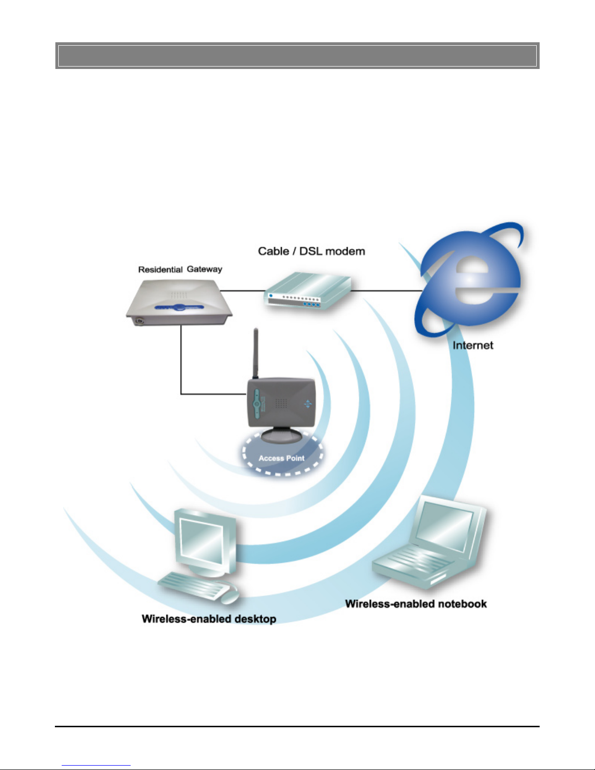
>>> 1.2 How AP54G Works
Infrastructure Mode: Infrastructure networking differs from
Ad-hoc networking is that it includes an Access Point. The Access Point enables users on a wireless LAN to access an existing
wired network, allowing wireless users to take advantage of the
wired networks resources, such as Internet, email, file transfer,
and printer sharing.
AP54G

3
>>> 1.3 Features and Benefits
54Mbps Data Rate/150-500ft Indoor Range
The access point runs with data-intensive applications like multimedia and streaming video/audio - even through walls, floors
and ceilings. You get high-speed networking without wires ideal for home office networking requirements.
Superior Antennas Design
One external dipole and one internal patch antennas provide
superior polarized reception and transmission for the best signal
quality.
Wi-Fi Compliant
This access point complies with IEEE802.11g standard and
Wi-Fi, allowing full interoperability with any Wi-Fi certified
wireless product.
Easy Installation
WDS repeater bridge mode support for easy network
deployment; in addition, the user-friendly web-based interface
and step-by-step Setup Wizard make the access point fast and
easy to install.
WPA Security to Ensure Privacy
Enhanced Security-WPA-compliant data encryption help protect your network from unauthorized access.

4
>>> 1.4 Specifications
Standard IEEE 802.11g/b, IEEE802.3u 10/100
Base-Tx
Data Rates IEEE 802.11b (Auto-Fallback):
- CCK @ 5.5 and 11Mbps
- DQPSK @ 2Mbps
- DBPSK @ 1Mbps
IEEE 802.11g (Auto-Fallback):
- OFDM @ 54, 48, 36, 24, 18, 12, 9,
and 6Mbps
Range Indoor: 150~500 feet,
Outdoor: 1000~1600 feet
Frequency 2.4GHz
Wireless Radio DSSS (Direct Sequence Spread
Type Spectrum) - OFDM with ACK
Modulation Type IEEE 802.11b: CCK, DBPSK, and
DQPSK
IEEE 802.11g: OFDM (BPSK, QPSK,
16QAM, 64QAM)
WEP Encryption 64/128-bit
Antenna One external dipole and one internal
patch
Protocols Support TCP/IP, DHCP Client, HTTP
Wired Interface One Ethernet IEEE 802.3u 10/100
Base-Tx, RJ-45 (Auto MDI/MDI-X)

5
User Selectable Network Mode, SSID, Channel, Tx
Settings Rate, RTS/CTS Threshold, Fragmenta-
tion Threshold, WEP, Mac Filtering,
Firmware Upgrade
LED Indicators WLAN, LAN, Power
Output Power 11b mode: 17±1dBm
11g mode: 13±1dBm @ 54Mbps
Sensitivity 54Mbps OFDM @ 10% PER = -67dBm
48Mbps OFDM @ 10% PER = -68dBm
36Mbps OFDM @ 10% PER = -72dBm
24Mbps OFDM @ 10% PER = -76dBm
18Mbps OFDM @ 10% PER = -79dBm
12Mbps OFDM @ 10% PER = -81dBm
11Mbps CCK @ 8% PER = -82dBm
9Mbps OFDM @ 10% PER = -83dBm
6Mbps OFDM @ 10% PER = -84dBm
5.5Mbps CCK @ 8% PER = -85dBm
2Mbps QPSK @ 8% PER = -86dBm
1Mbps BPSK @ 8% PER = -89dBm
Power Consumption Max. 4 watts (continuous transmit
mode)
Power Adapter 110~120AC (USA, Canada)
220~240AC (Europe)
DC output: 12VDC
Output current: 500mA

6
>>> 1.5 Package Contents
Unpack the package and check all the items carefully. If any item
contained is damaged or missing, please contact your local dealer
as soon as possible. Also, keep the box and packing materials in
case you need to ship the unit in the future.
The package should contain the following items:
- One Wireless 11g Access Point - AP54G.
- One Stand.
- One Power Adaptor (12VDC/500mA).
- One Installation CD-ROM including the manual files.

7
Unit Description
>>> 2.1 Front View
LEDs
Indicate the power and
traffic utilization status.
Antenna
External dipole antenna.
Stand
8
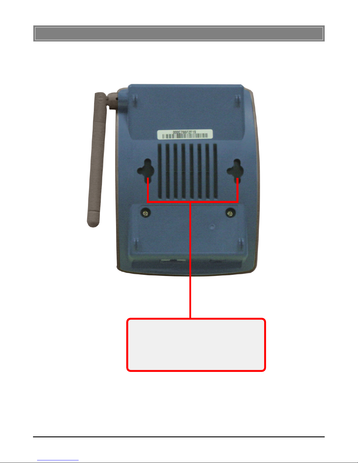
>>> 2.2 Bottom View
Mounting Holes
The mounting distance between the mounting
holes is 5.5cm. (For information on how to
use the mounting holes, refer to Wall- or
Ceiling-mounted Installation in Chapter 3.)
9
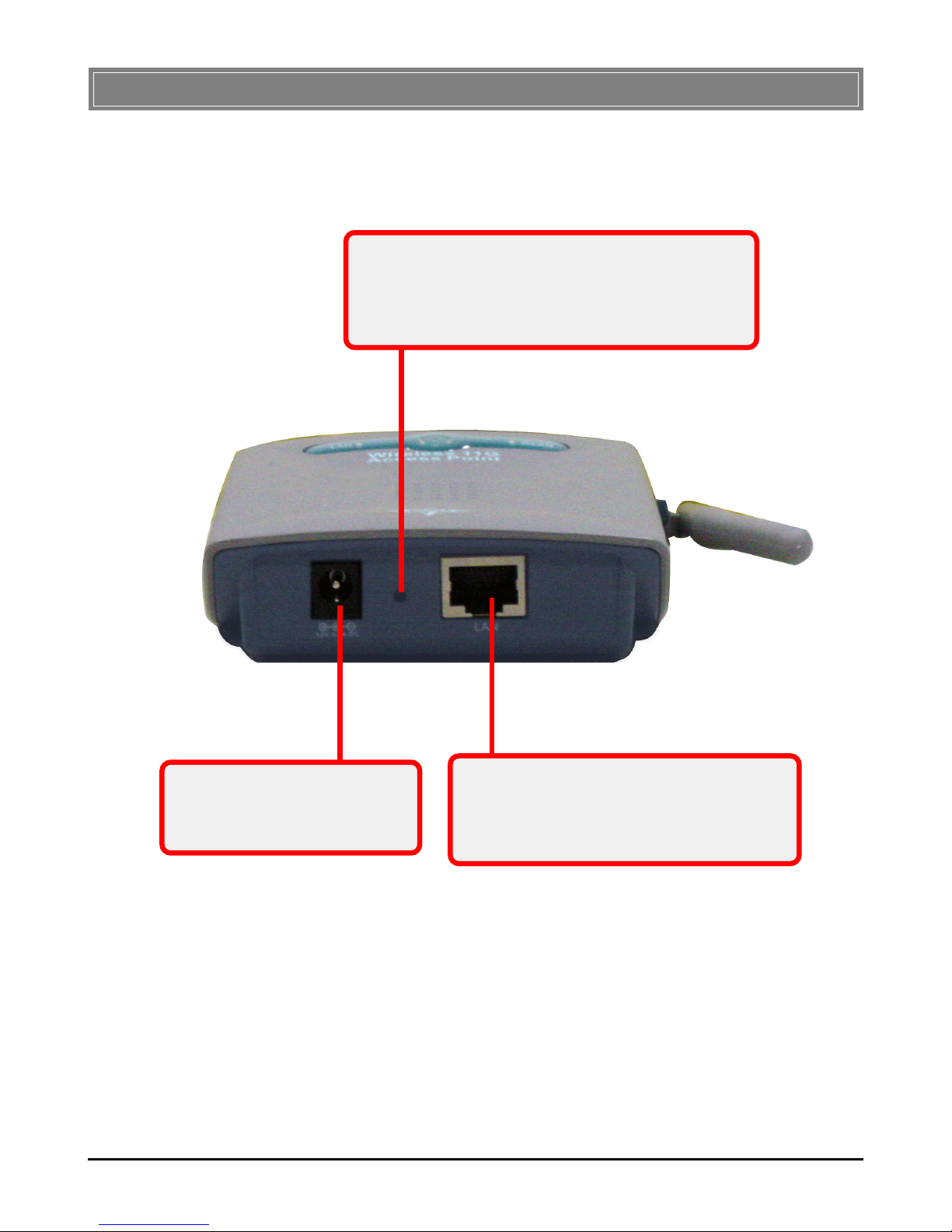
>>> 2.3 Side View
Power Jack
Power jack with input voltage
at 12VDC/500mA.
RJ-45 Ethernet Jack
This RJ-45 connector allows your Access
Point to be connected to a network
environment.
Reset Button
Press and hold this button for a duration of
> 5 seconds - reload the factory default settings.
< 5 seconds - reset the system.
10
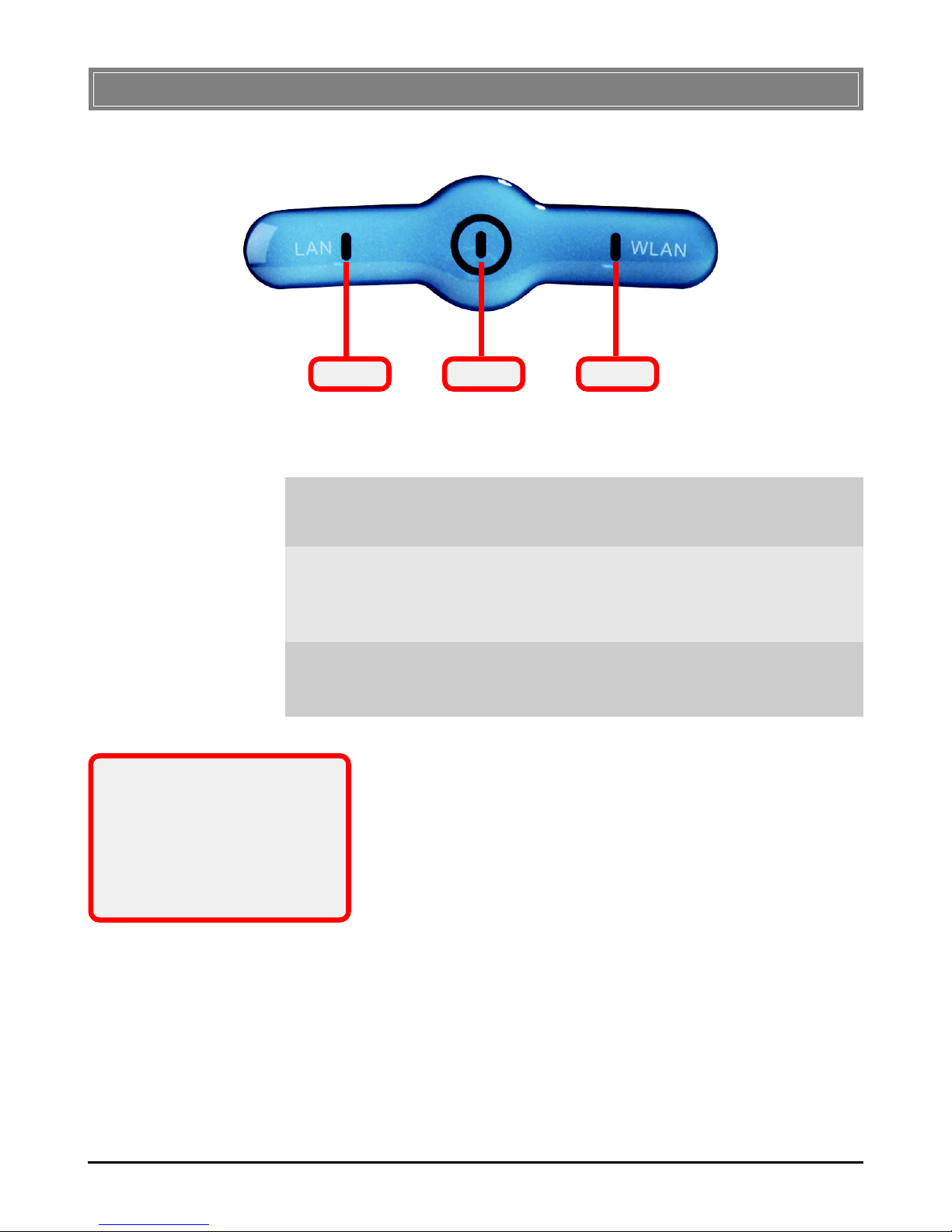
>>> 2.4 LEDs
Power
LAN WLAN
Power: a steady Blue light glows to indicate the power adapter
is connected.
LAN: the Green light glows when the access point is connected to the network; it blinks to indicate the traffic through
this port.
WLAN: the Green light blinks to indicate the status of the
access point’s wireless networking*.
* The WLAN LED will blink
slowly when the firmware
failed. In this event, you have
to resume the firmware.
Please see Appendix B for
detailed instructions.

11
Hardware Installation
>>> 3.1 Installing Your Access Point
Positioning
The access point can be free-standing, wall- or ceiling-mounted
(refer to 3.2 Free-standing Installation and 3.3 Wall- or Ceiling-
mounted Installation). Before making the access point workable,
please note that the access point should be placed in a location
with the followings:
- Easy accessibility: you can conveniently connect the
access point to the xDSL/Cable Modem through the
Ethernet port.
- Easy LEDs observation: you may monitor the real-time
networking status and take instant measures as
problems arise.
- Maximum wireless coverage: to achieve the maximal
coverage, the access point should be placed at a high
level in position without obstacles and defiladed space.
No matter how you install the access point - in a wallmounted or free-standing fashion, remember the antenna
should always point vertically upward.
Connecting Cables
1. Plug the DC end of the power adapter into the
connector of the access point, and the AC end to the
wall outlet later.
2. For wired connection, connect the access point to the
LAN port.
Power Up
When the DC end of the power adapter is connected to the
access point, plugging the AC end of the power adapter to the
wall outlet will power up the system immediately.
 Loading...