

Page 1

MSI RG54GS (MS-6822)
Wireless 11g Residential Gateway
User’s Guide
G52-C6822X8
Page 2

FCC Caution
1. The device complies with Part 15 of the FCC rules. Operation is subject to
the following two conditions:
(1) This device may not cause harmful interference, and
(2) This device must accept any interference received, including interference
that may cause undesired operation.
2. FCC RF Radiation Exposure Statement: The equipment complies with FCC
RF radiation exposure limits set forth for an uncontrolled environment.
This equipment should be installed and operated with a minimum
distance of 20 centimeters between the radiator and your body.
3. This Transmitter must not be co-located or operating in conjunction with
any other antenna or transmitter.
4. Changes or modifications to this unit not expressly approved by the
party responsible for compliance could void the user authority to operate
the equipment.
Copyright Notice
The material in this document is the intellectual property of MICRO-STAR INTERNATIONAL. We take every care in the preparation of this document, but no guarantee is
given as to the correctness of its contents. Our products are under continual improvement and we reserve the right to make changes without notice.
Trademarks
Microsoft Windows and Internet Explorer are registered trademarks or trademarks of
Microsoft Corporation.
All brand names, icons, and trademarks used in this manual are the sole property of their
respective owners.
Revision History
Revision History Date
V 1.1 First Release January 2004
Page 3

Important Safety Precautions
Always read and follow these basic safety precautions carefully when handling any
piece of electronic component.
1. Keep this User’s Guide for future reference.
2. Keep this equipment away from humidity.
3. Lay this equipment on a reliable flat surface before setting it up.
4. The openings on the enclosure are for air convection hence protects the
equipment from overheating.
5. All cautions and warnings on the equipment should be noted.
6. Never pour any liquid into the opening that could damage or cause electrical
shock.
7. If any of the following situations arises, get the equipment checked by a
service personnel:
Liquid has penetrated into the equipment
The equipment has been exposed to moisture
The equipment has not work well or you can not get it work
according to User’s Manual
The equipment has dropped and damaged
If the equipment has obvious sign of breakage
8. DO NOT LEAVE THIS EQUIPMENT IN AN ENVIRONMENT
UNCONDITIONED, STORAGE TEMPERATURE ABOVE 60O C OR
BELOW -20OC, IT MAY DAMAGE THE EQUIPMENT.
Page 4

How to Use This Guide
This User’s Guide provides instructions and illustrations on how to install and use your
MSI RG54GS - the Wireless 11g Residential Gateway.
Chapter 1, Introduction, provides a general information on the product you
bought, including its application, specification, and requirements.
Chapter 2, Hardware Installation, tells you how to install the product into
your system.
Chapter 3, Configuration, describes the Configuration Utility that lets you
configure your product to connect the network quickly and easily.
Chapter 4, Using the Print Server, helps you to install and use the USB
printer as a print server in your network.
Appendix, includes the instructions of assigning a fixed IP address and
resuming the firmware.
Please note that the setting diagrams or values in this guide are FOR YOUR REFER-
ENCE ONLY. The actual settings and values depend on your system and network. If
you are not sure about these information, please ask your network administrator or MIS
staff for help.
Technical Support
Visit the MSI website for FAQ, technical guide, driver and software updates,
and other information: http://www.msi.com.tw/.
Contact our technical staff at: [email protected].
Page 5

Table of Contents
1. Introduction ......................................................................................................... 1
1.1 MSI RG54GS - Wireless 11g Residential Gateway ....................................... 1
1.2 Networking Options ....................................................................................... 2
1.3 Features and Benefits ..................................................................................... 3
1.4 Package Contents ............................................................................................ 4
1.5 System Requirements ..................................................................................... 4
1.6 Specifications .................................................................................................. 5
2. Hardware Installation ......................................................................................... 9
2.1 Product View .................................................................................................. 9
2.2 Connections Ports .......................................................................................... 10
2.3 LEDs ............................................................................................................... 11
2.4 Installing Your RG54GS ................................................................................. 12
2.4.1 Positioning .............................................................................................. 12
2.4.2 Connecting Cables .................................................................................. 12
2.4.3 To Power Up .......................................................................................... 13
3. Configuration ...................................................................................................... 15
3.1 Configuration Utility ...................................................................................... 15
3.2 Typical Configuration ..................................................................................... 17
3.3 Customized Configuration .............................................................................. 21
3.3.1 System ....................................................................................................22
3.3.2 Internet ................................................................................................... 24
3.3.3 LAN ........................................................................................................ 26
3.3.4 Wireless .................................................................................................. 28
3.3.5 NAT ........................................................................................................ 30
3.3.6 Firewall ................................................................................................... 31
3.3.7 Printer .....................................................................................................33
4. Using the Print Server ........................................................................................ 35
4.1 For Windows 98SE/ME User ......................................................................... 35
Page 6

4.1.1 Installing the LPD Client Utility ............................................................ 35
4.1.2 Installing the Printer Driver .................................................................... 37
4.1.3 Configuring the LPD Port ....................................................................... 39
4.2 For Windows 2000/XP User ..........................................................................41
4.2.1 Installing the Printer Driver .................................................................... 41
4.2.2 Configuring the LPD Port ....................................................................... 44
Appendix .................................................................................................................... 49
A - Assigning a Fixed IP Address ........................................................................... 49
B - Resuming the Previous Firmware .................................................................... 53
Page 7

1
Introduction
>>> 1.1 MSI RG54GS - Wireless 11g
Residendtial Gateway
MSI RG54GS Wireless Residential Gateway (hereafter called
RG54GS), compliant with IEEE802.11g and IEEE802.11b, is
designed for high throughput and fully function that leads you
into the wireless network environment. In the rapid growing
network environment, MSI RG54GS acts as a home-end device
that connects your computer to the WAN service (e.g. the
Internet). With the RG54GS, networking and sharing information throughout the house/office become an easy and flexible
task. In addition, the RG54GS is also a switching device as an
aggregating point of the wireless LAN and wired LAN clients,
and as a router between LAN and WAN traffic. It also provides
a USB printer port to act as a print server in your network.
Combined the SPI firewall, wireless Access Point, Print Server,
and LAN switch into a compact package, the MSI RG54GS can
provide you with the essential security and IP sharing function.
These features build the RG54GS as a cutting-edge, cost-effective device that fits to SOHO/home application.
Page 8
2
>>> 1.2 Networking Options
MSI RG54GS is a Base Station that bridges communication
between computers (via wireless networking), and connects
the computers to the Internet.
You can use the RG54GS in the following applications:
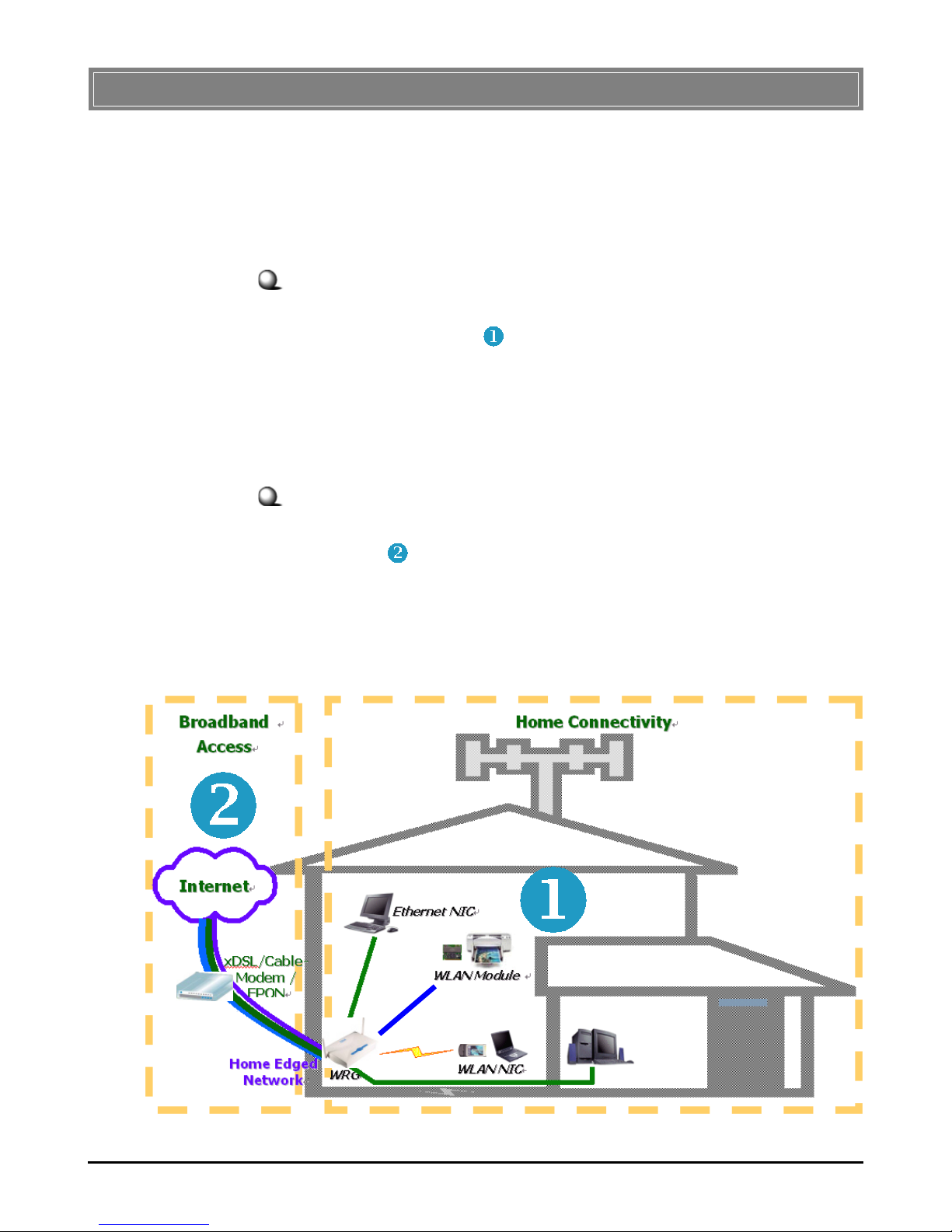
Home connectivity
A stand-alone wireless network. As shown in the right part of
the diagram below ( ), the out-of-the-box mode of operation
for the RG54GS that allows your client stations to share files
and printers. Adding wireless computers is as easy as inserting
a wireless client adapter and configuring the computer with the
same Network Name and Key.
Broadband access
A wireless/wired Internet access via xDSL/Cable Modem or
Ethernet ( ). To access the Internet via a xDSL/Cable or ISDN
modem, you will need to:
- Connect the external modem to the RG54GS using a
LAN cable.
- An ISP (Internet Service Provider) account.
Typical Configuration of Wireless LAN
Page 9

3
With MSI RG54GS, your network can immediately upgrade to
a wireless network, providing wireless access to the LAN and
WLAN, and sharing information and printers in the network.
54 Mbps Data Rate (max.)/150-400 ft. Indoor Range
The RG54GS runs with data-intensive applications like MP3,
multimedia, gaming and streaming video/audio - even through
walls, floors and ceilings. You can get Ethernet quality networking without wires and cables - ideal for standard networking requirements.
Superior Antenna Design
Dual dipole antennas provide superior polarized reception and
diversity transmission for the best signal quality.
Interoperable with any 802.11g Compliant Device
The RG54GS complies with IEEE 802.11g standard and Wi-Fi,
allowing full interoperability with any Wi-Fi certified wireless
product.
Easy to Install and Use
The Configuration Utility with user-friendly and Web-based
interface provides step-by-step instructions, making the
RG54GS fast and easy to be installed and used in the network.
WEP Security to Ensure Privacy
Supports 64-/128-bit WEP encryption, which ensures that your
network signal is secure and private inband and outband of
your home and office.
Scalability
The RG54GS can be configured in every way to meet your
needs of specific applications and installations. It also provides Flash memory for easy firmware upgrade.
>>> 1.3 Features and Benefits
Page 10
4
>>> 1.4 Package Contents
>>> 1.5 System Requirements
After installing the RG54GS, you need the followings to configure respective network settings:
- A network-enabled computer.
- Windows 98SE/ME/2000/XP; Linux; Macintosh.
- A JavaScript-enabled web browser, such as Internet
Explorer 5.0 and Netscape 6.0.
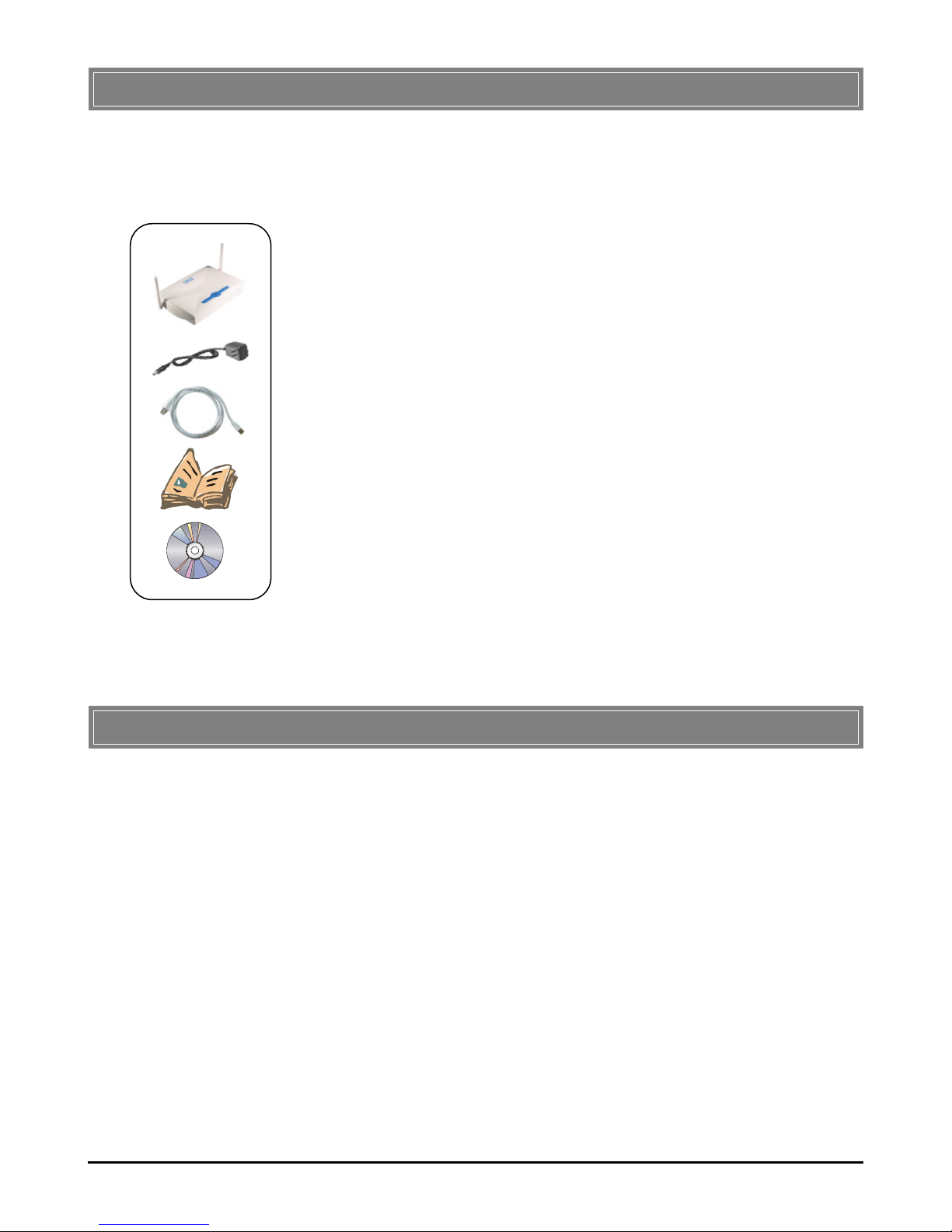
Unpack the package and check all the items carefully. If any
item contained is damaged or missing, please contact your local
dealer immediately. Also, keep the box and packing materials in
case you need to ship the unit in the future. The package
should contain the following items:
- One Wireless 11g Residential Gateway - RG54GS.
- One AC Power Adapter, 12VDC/1A output.
- One Ethernet cable (RJ-45).
- One Quick Start Guide.
- One CD-ROM including User’s Manual and Quick Start
Guide.
Page 11

5
>>> 1.6 Specifications
Standard Compliance - IEEE802.11g/IEEE802.11b/
IEEE802.3/IEEE802.3u
- USB 1.1
Internet Protocol TCP/IP, NAT, DHCP, HTTP,
Supported PPPoE, PPTP, DNS, LPR,
SNTP
Operating Temperature 0 ~ 55OC (32 ~ 122OF)
Storage Temperature -30 ~ 70OC (-22 ~ 158OF)
Operating Humidity 0 ~ 85% @ 40OC (104OF),
non-condensing
Wired Data Rates 10/100Mbps auto-negotiating
(full-duplexing switch)
Wireless Data Rates IEEE802.11b (auto-fallback)
- CCK: 11, 5.5Mbps
- DQPSK: 2Mbps
- DBPSK: 1Mbps
IEEE802.11g (auto-fallback)
- OFDM: 54, 48, 36, 24, 18,
12, 9, and 6Mbps
Wireless Range Open Space:
- ≥ 170m @ 11Mbps
- ≥ 50m @ 54Mbps
Indoor:
- ≥ 120m @ 11Mbps
- ≥ 20m @ 54Mbps
Wireless Transmission 17±1dBm
Power
General
Performance
Page 12

6
LAN
Device
Management
Number of Ports Four 10/100Mbps switched
Ethernet ports (RJ-45)
Number of PCs Up to 253 PCs
Supported
Routing NAT, TCP/IP
Number of Ports One 10/100Mbps Fast
Ethernet port for cable/xDSL
modem (RJ-45)
Firewall - IP/Port Address Forwarding
Filtering
- MAC Address Forwarding
Filtering
- MAC Address Associating
Filtering
- DoS Prevention
- Application Layer Gateway
- Virtual DMZ
- SPI
Tools Web-based browser; event
log; login password
LEDs Power, LAN/WAN/WLAN
port activity, USB port
Dimensions (WxDxH) 180 x 127.7 x 32mm
Weight 295g
Antenna Dipole type with dual external
antenna
Input Voltage 12VDC (includes AC adapter)
WA N
Physical
Specification
Page 13

7
U.S. FCC Part 15 class B, Wi-Fi
Europe CE
Certifications
Page 14

8
Page 15
9
This chapter provides a quick introduction to your RG54GS,
including product view, installation and power up.
Hardware Installation
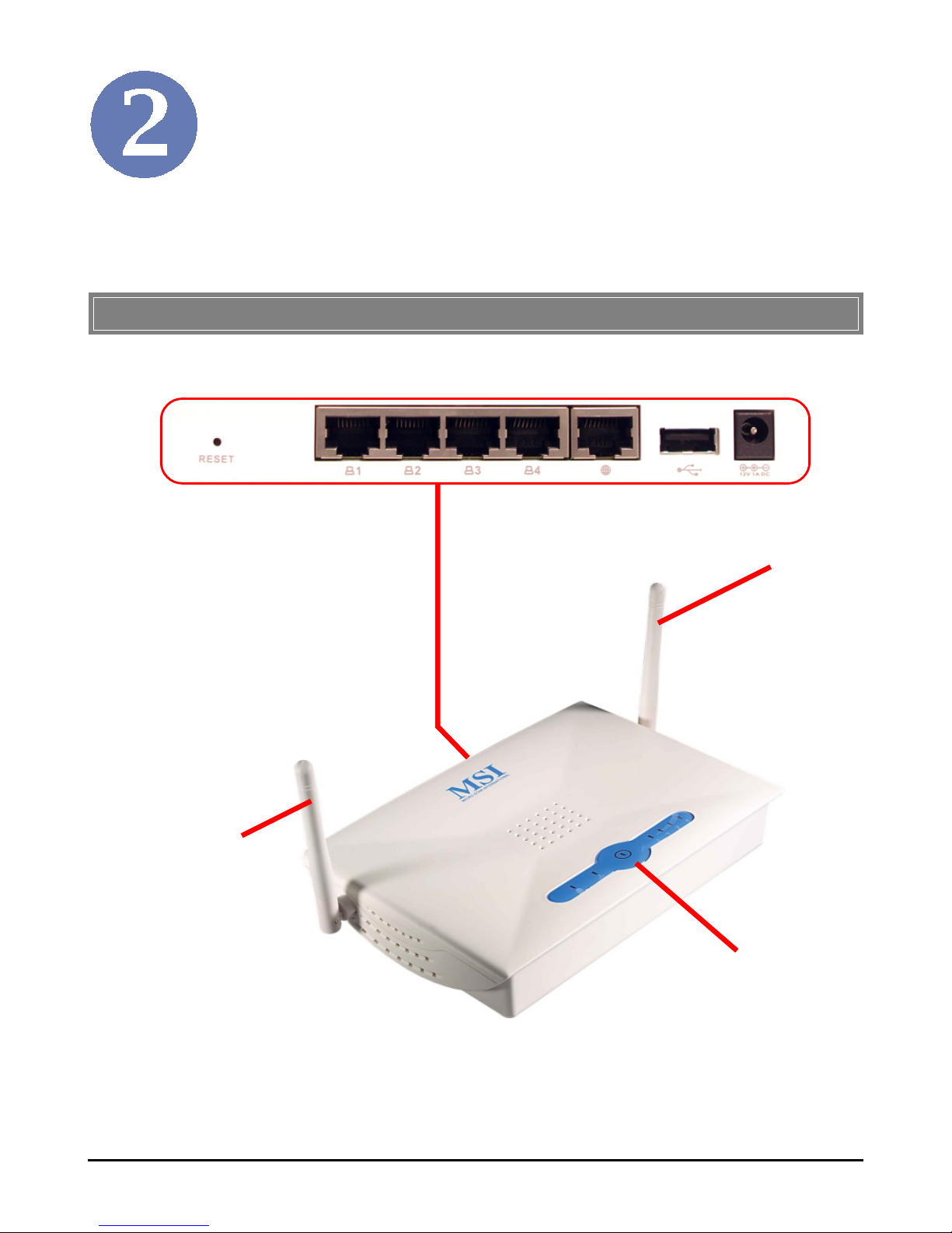
>>> 2.1 Product View
RG54GS
Connection Ports
LEDs
Antenna
Antenna
Page 16
10
>>> 2.2 Connection Ports
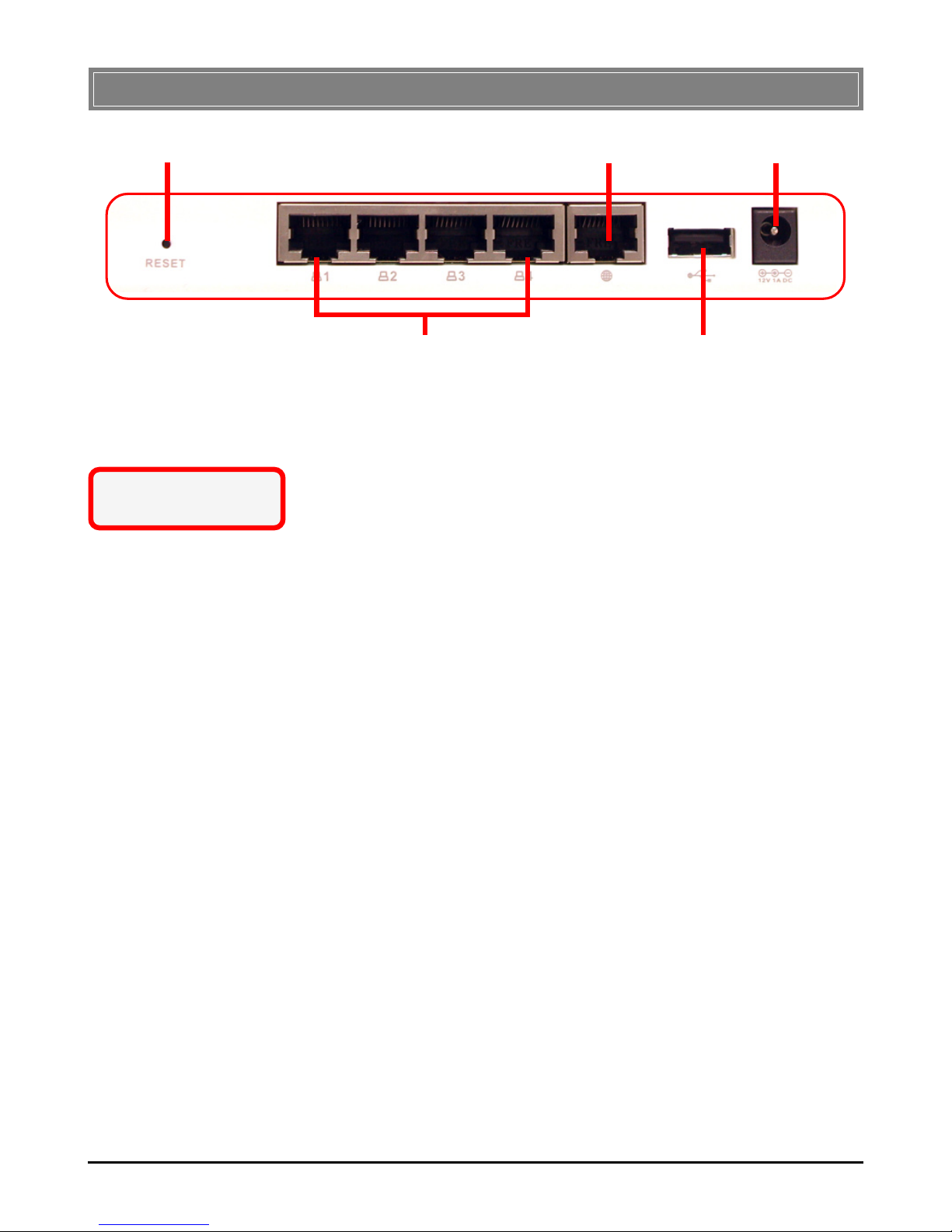
LAN Ports 1~4 USB Port
Reset Button WAN Port Power Connector
Reset Button
1. Press and hold* this button longer than 1 second
to restart the RG54GS.
2. Press and hold* this button longer than 5 seconds,
the system will reload the factory default settings.
LAN Ports 1~4
The RG54GS provides four 10/100Mbps Fast Ethernet ports,
allowing connection to the computers and other network devices.
WAN Port
This 10/100Mbps Fast Ethernet port provides connection to
your xDSL/Cable Modem or Ethernet connection.
USB Port
The USB 1.1 port is used to connect the printer to provide
print server function.
Power Connector
Connect the enclosed power adapter and provide power to the
RG54GS.
* Use a pointed object
(e.g. a stretched clip)
Page 17
11
>>> 2.3 LEDs
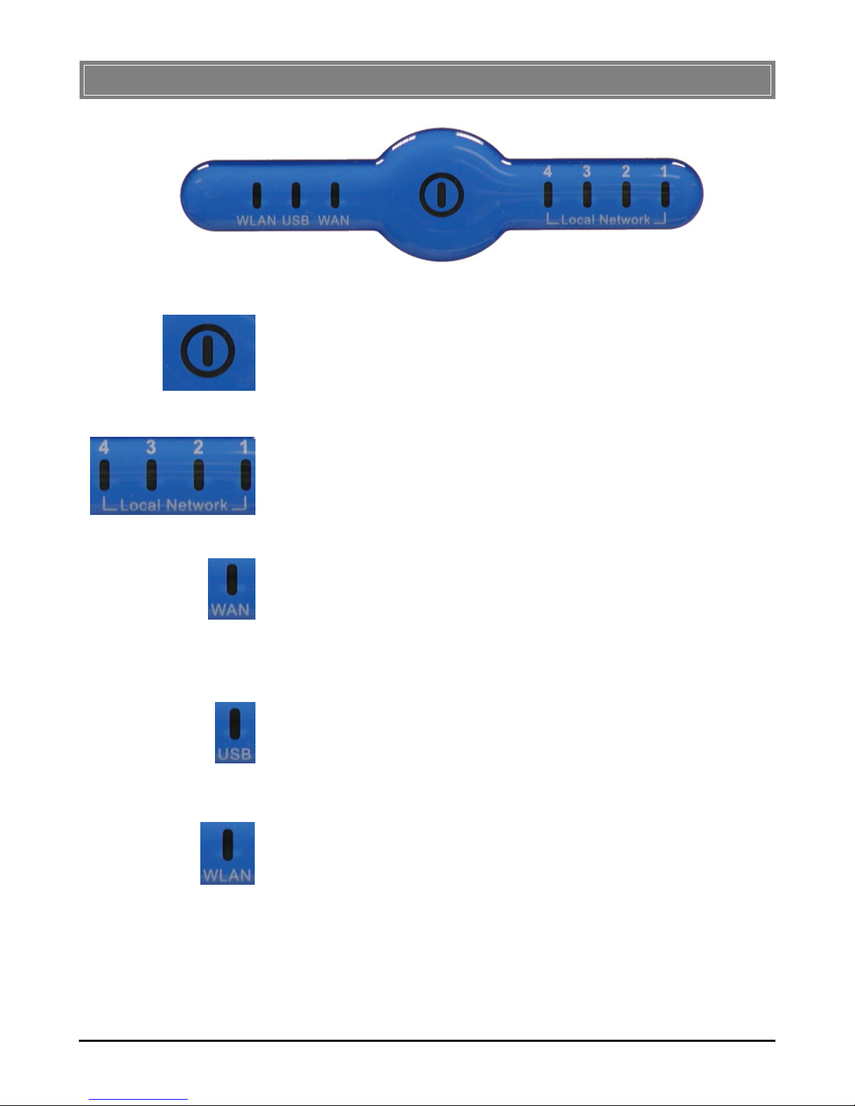
Power
A steady Blue light glows to indicate the power adapter is
connected.
LAN 1~4
The Green light glows when there is a computer/device connected to respective port.
WA N
A Green light glows when the system connects to the xDSL/
Cable Modem or Ethernet connection, and it will blink when
receiving/transmitting data on the link.
USB
A Green light glows when the USB printer is connected to the
RG54GS.
Wireless Status
A Green light glows to indicate the status of RG54G’s wireless
networking.
Page 18
12
>>> 2.4 Installing Your RG54GS
Positioning
To operate normally, the RG54GS should be put on a flat surface,
and do not put any heavy object on it. Before connecting
RG54GS to your devices, please note that the RG54GS should
be placed in a location where is:
- Easy to access, so that you can conveniently connect it
to the xDSL/Cable Modem through the WAN port, and
to the computers/devices through the LAN ports.
- Allows you to observe the LEDs clearly, so that you
may monitor the real-time networking status and take
instant measures as problems arise.
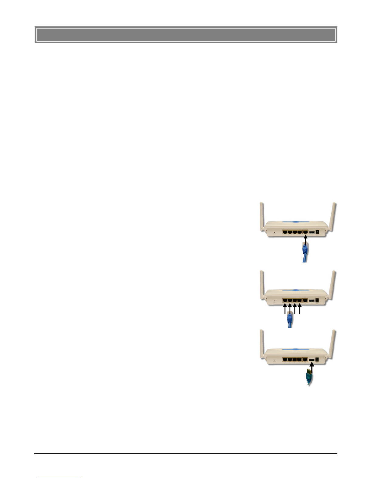
Connecting Cables
1. To access to the Internet,
connect one end of an
Ethernet cable to the WAN
port of RG54GS, and the
other end to your xDSL/Cable
Modem.
2. For wired connection to the
network devices, connect
one end of an Ethernet cable
to the LAN port (1~4) of
RG54GS, and the other end
to your computers/devices.
3. To connect the USB printer,
connect one end of the USB
cable to the USB port of
RG54GS, and the other end
to your printer.
4. For wireless connection, install the wireless adapters
onto your computers, and you have to configure
respective settings on your computers (refer to your
wireless adapter's manual) to take full advantages of
your RG54GS.
2.4.1
2.4.2
Page 19
13
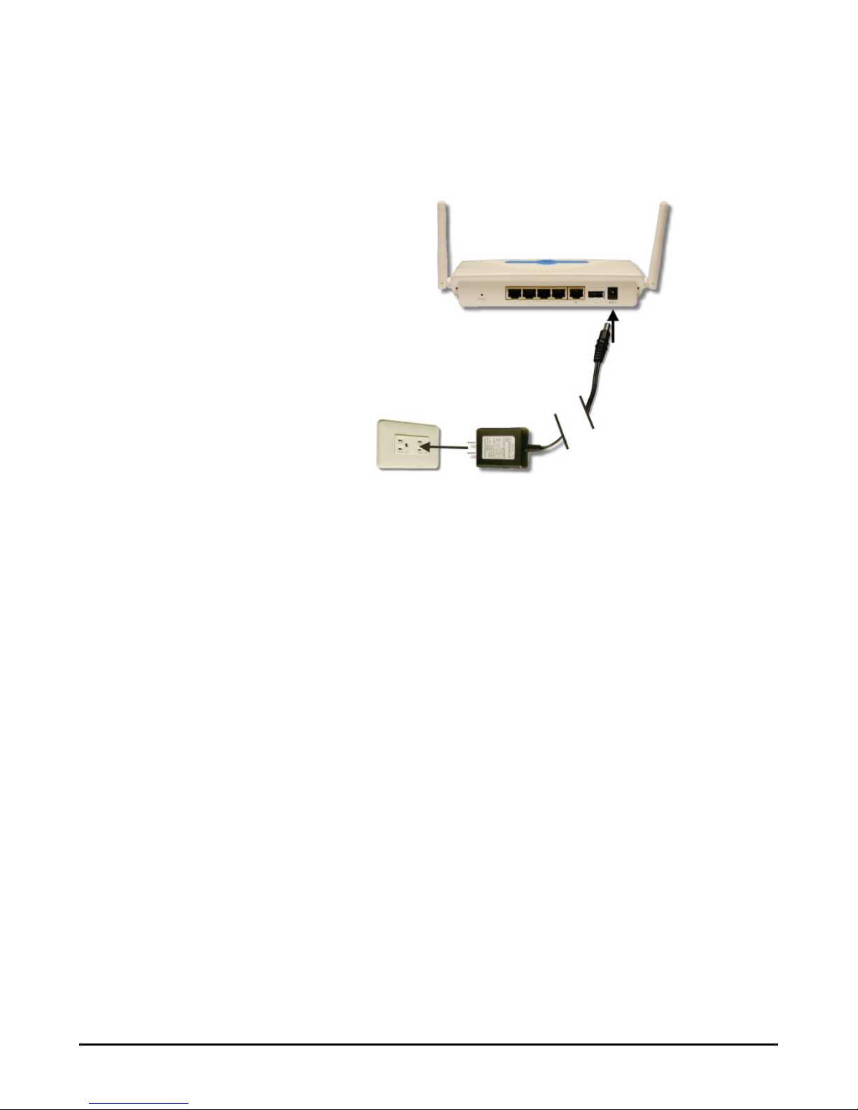
To Power Up...
Plug the DC end of the power adapter into the power connector
of RG54GS; then, plug the AC end to an electrical outlet. The
RG54GS is powered up immediately.
2.4.3
Page 20

14
Page 21
15
Configuration
>>> 3.1 Configuration Utility
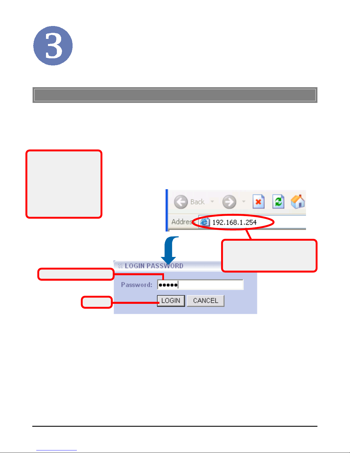
* admin is the default
password setting of the
wireless gateway, and
can be changed in the
Configuration Utility.
Refer to section 3.3.1
for details.
Since the RG54GS supports DHCP Server and which is enabled by default, the computer connected to it is automatically
assigned a dynamic IP address that is allowed to enter the Configuration Utility. Otherwise, you have to assign a fixed IP
address to this computer within the IP address range of the
RG54GS. For example, you can assign a fixed IP address of
192.168.1.253 with a Subnet Mask of 255.255.255.0. (For more
instruction, please refer to Appendix - A, Assigning a Fixed IP
Address.)
The MSI RG54GS provides you with a convenient utility to
customize the network settings. Whenever you want to
configure the respective settings, open your web browser (e.g.
Internet Explorer), and type the default IP address 192.168.1.
254 in the Address bar and press [Enter]. When the password
page appears, type admin* in the Password box and click
LOGIN.
Click
Enter the Password
Open the web browser and
enter the IP Address of the
wireless gateway.
Page 22
16
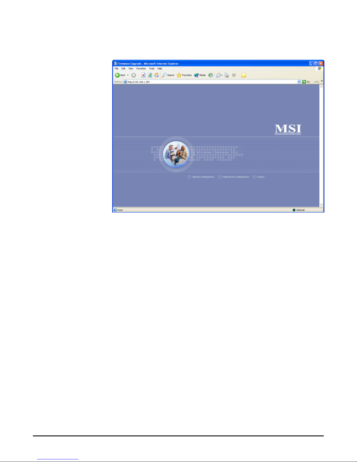
The Home window of the Configuration Utility will appear as
below, which provides three options to select: Typical
Configuration, Customized Configuration, and Logout.
Home Window of the Configuration Utility
- Typical Configuration: Provides a step-by-step
Setup Wizard to guide you through the basic settings of
the gateway. Generally, after completing the four steps
in this option, your gateway can connect to the ISP.
- Customized Configuration: Allows you to customize the network settings of your gateway for some specific purposes, such as changing password, updating
firmware, and configuring other network settings.
- Logout: Allows you to exit the utility and return to
the password page.
Page 23
17
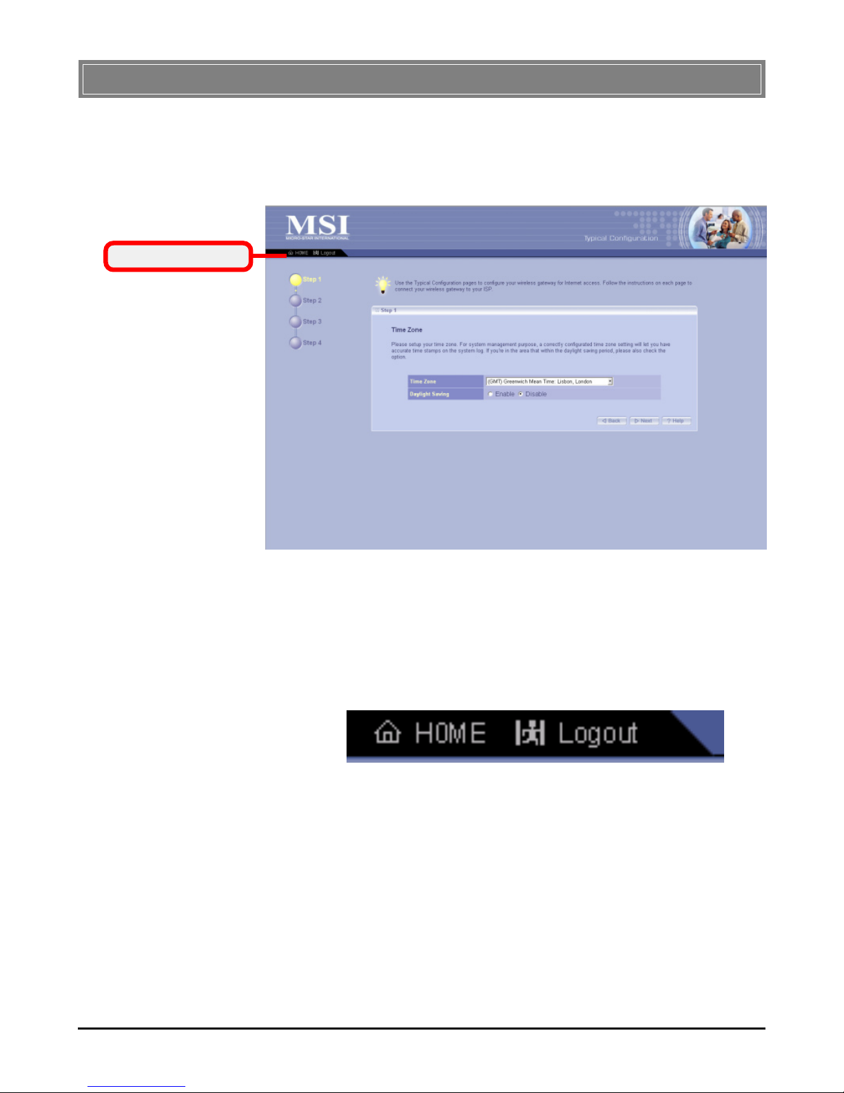
Click Typical Configuration in the Home window of the Con-
figuration Utility, and the Setup Wizard appears from Step 1 to
guide you through the configuration.
Setting the Time Zone
First, you should set the Time Zone. For system management purpose, a correct time zone setting will let you have
accurate time stamps on the system log. If you are in the
area that within the daylight saving period, please also check
the Daylight Saving option.
When completed, click Next to continue step 2.
- The Menu Bar: During the Setup Wizard, whenever
you click HOME in the menu bar will make you return
to the Home window; click Logout to exit the Configuration Utility.
Step 1. Setting the Time Zone
The Menu Bar
The Menu Bar
>>> 3.2 Typical Configuration
Step 1.
Page 24
18
Setting the Connection Type
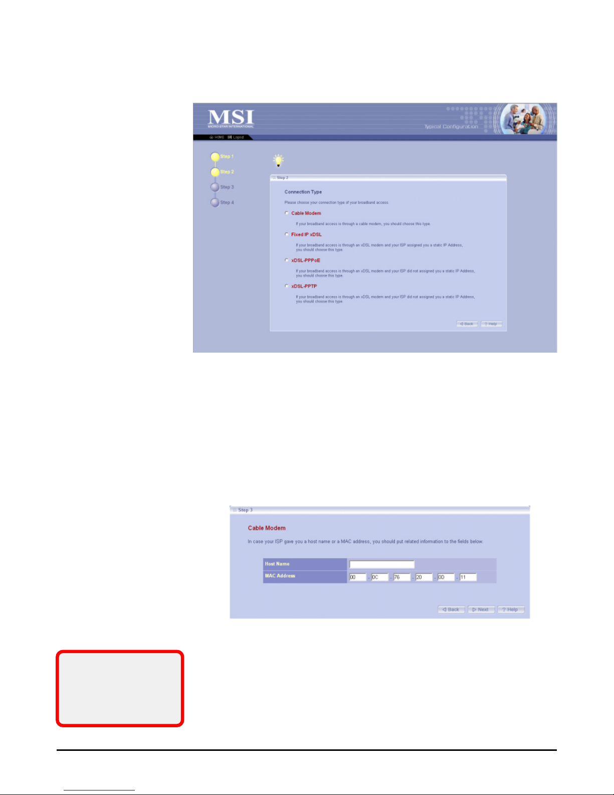
According to the connection type your are using, click the respective option to configure the settings.
Step 2. Setting the Connection Type
If your ISP provides you with a Host Name or a locked MAC
Address, you should enter these information in the respective
fields.
Setting the Connection Type (continue)
- Cable Modem:
If your broadband access is through a cable modem, select this
option.
Step 2.
If you are not sure on
these settings, please
ask your ISP for
assistance.
Step 3.
Page 25
19
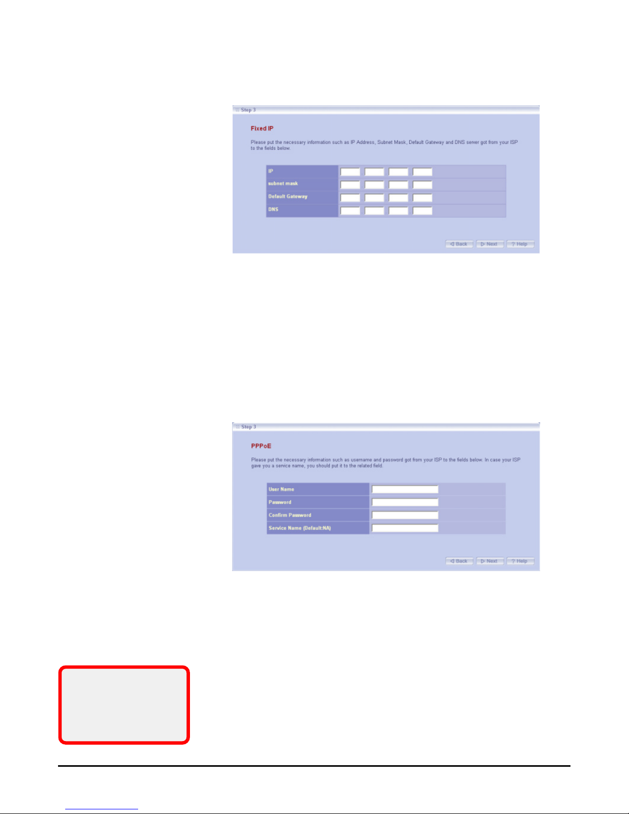
- Fixed-IP xDSL:
If your broadband access is through an xDSL modem and your
ISP assigned you a static IP address, select this option.
Enter the necessary information in the respective fields, such as
the IP address, Subnet Mask, Default Gateway and DNS server
provided by your ISP.
- xDSL-PPPoE:
If your broadband access is through an xDSL modem and your
ISP did not assign you a static IP address, select this option.
Enter the necessary information in the respective fields, such as
the user name and password provided by your ISP. If your ISP
gave you a service name, you should put it to the respective
field (the default is none).
If you are not sure on
these settings, please
ask your ISP for
assistance.
Page 26
20
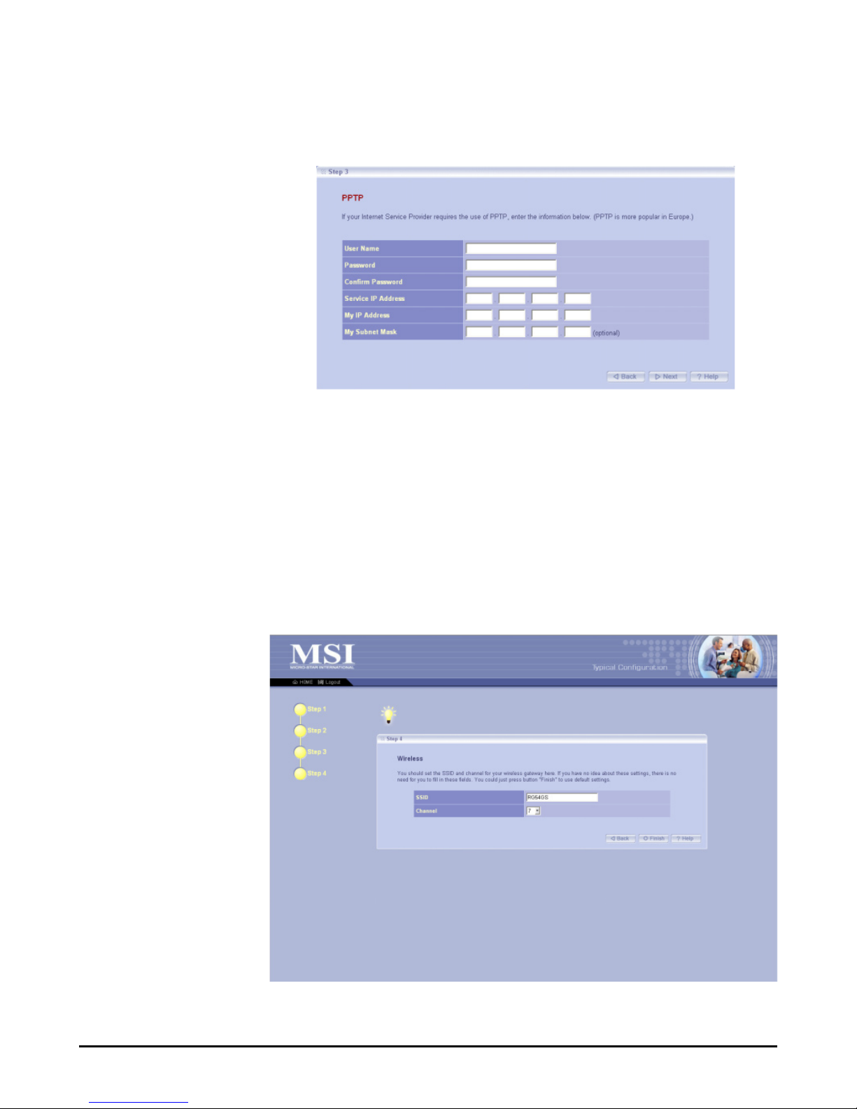
- xDSL-PPTP:
If your broadband access is through an xDSL modem and your
ISP did not assign you a static IP address, select this option.
(This option is used mostly in Europe.)
Enter the necessary information in the respective fields, such as
the user name and password provided by your ISP.
When completed, click Next to continue step 4.
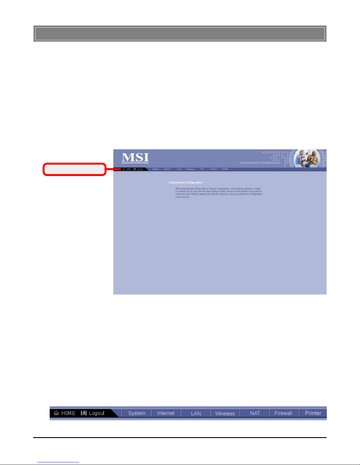
Setting the Wireless Network Settings
You could set the SSID (Network Name) and channel for your
wireless gateway.
When completed, click Finish to save your settings and exit the
Configuration Utility.
Step 4.
Page 27
21
Typically, your wireless gateway will have no problem to connect to your ISP and let internal clients to access to the Internet
without any problem after going through all steps in Typical
Configuration. If you want to customize your wireless gateway for some specific purposes, you may perform the configuration here.
Click Customized Configuration in the Home window of the
Configuration Utility, and the main window appears as below.
Main Window of Customized Configuration
- The Menu Bar: There is a menu bar in the top of the
Customized Configuration window, where contains two
options to exit the configuration window (HOME and
Logout, as described in page 17); and seven options for
advanced configuration: System, Internet, LAN, Wire-
less, NAT, Firewall and Printer, each one allows you
to configure the respective settings and view the system status.
>>> 3.3 Customized Configuration
The Menu Bar
The Menu Bar
Page 28
22
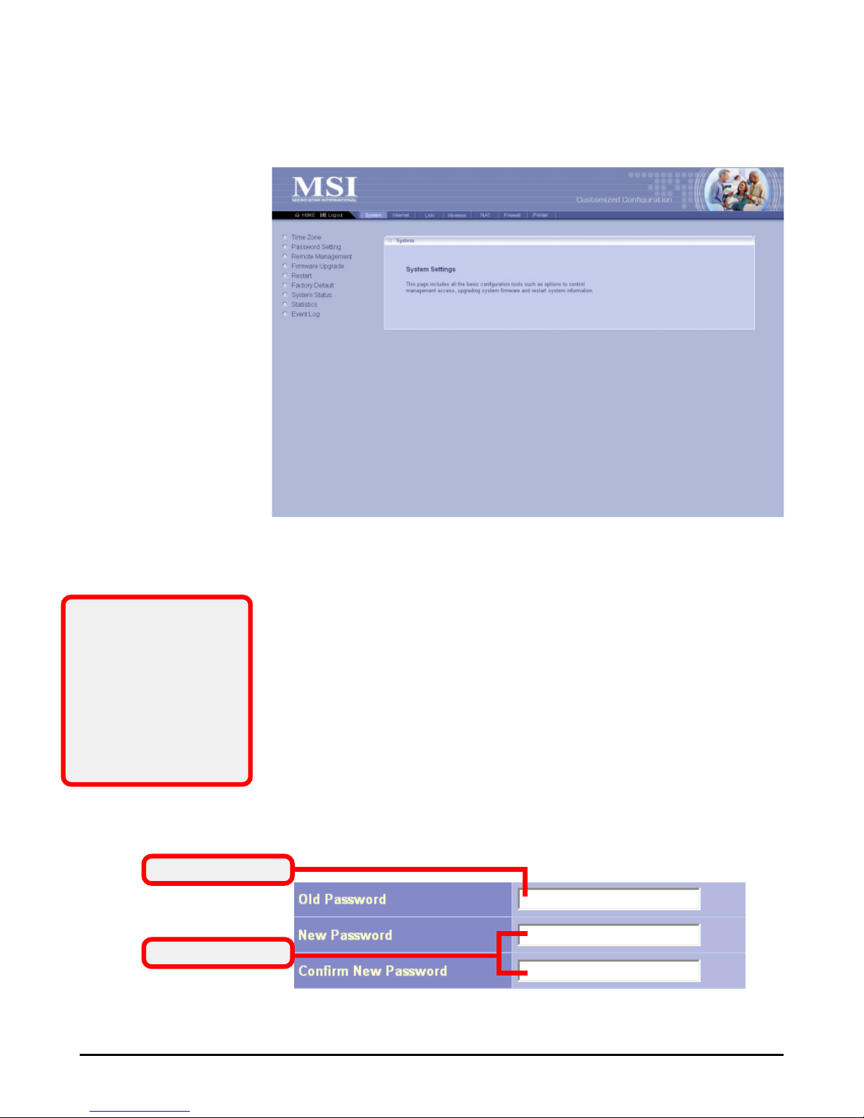
System
This page includes all the basic configuration tools such as
options to control management access, upgrade system firmware and restart system.
> Time Zone
For system management purpose, a correct time zone setting
will let you have accurate time stamps on the system log. If
you use the wireless gateway in the country adopting the Daylight Saving Time, please check the Daylight Saving option.
> Password Setting
The wireless gateway is shipped with default password admin.
This option allows you to use other password to replace the
old password. First, enter the old password, and then enter the
new password twice to confirm the password changed. Then,
click Apply to save the settings.
This window includes:
> Time Zone
> Password Setting
> Remote Management
> Firmware Upgrade
> Restart
> Factory Default
> System Status
> Statistics
> Event Log
3.3.1
Tip: Once you have
changed the settings in
each option, click
Apply to save the
settings, or Cancel to
abandon. Clicking
Help can bring up the
help window.
Old Password
New Password
Page 29

23
> Remote Management
Setting to Enable allows you to manage your wireless gateway
through WAN connection.
> Firmware Upgrade
Once you obtained a new version of firmware (e.g. downloading form the MSI website), you can update the firmware of
your wireless gateway. Click Browse to point to the firmware
file, and then click Upgrade to start.
IMPORTANT: If power failure occurs during upgrading firmware, the
RG54GS provides a second way to resume the previous firmware. For
more information, refer to Appendix B, Resuming the Previous Firmware.
> Restart
Clicking Restart allows you to restart your gateway through the
Configuration Utility, without unplugging the power cable or
pressing the Reset button longer than 1 seconds.
> Factory Default
Clicking Restore allows you to resume the factory settings of
your gateway. This function is the same as pressing the Reset
button (on the front panel) longer than 5 seconds.
> System Status
This option contains detail information of your gateway, including general information and respective network settings.
> Statistics
This option contains the statistics of your gateway, such as
respective networking statistics, allowing you to monitor the
device clearly. Click Refresh to re-load the statistics.
> Event Log
Select this option to display a list containing the event log of
your gateway.
Page 30
24
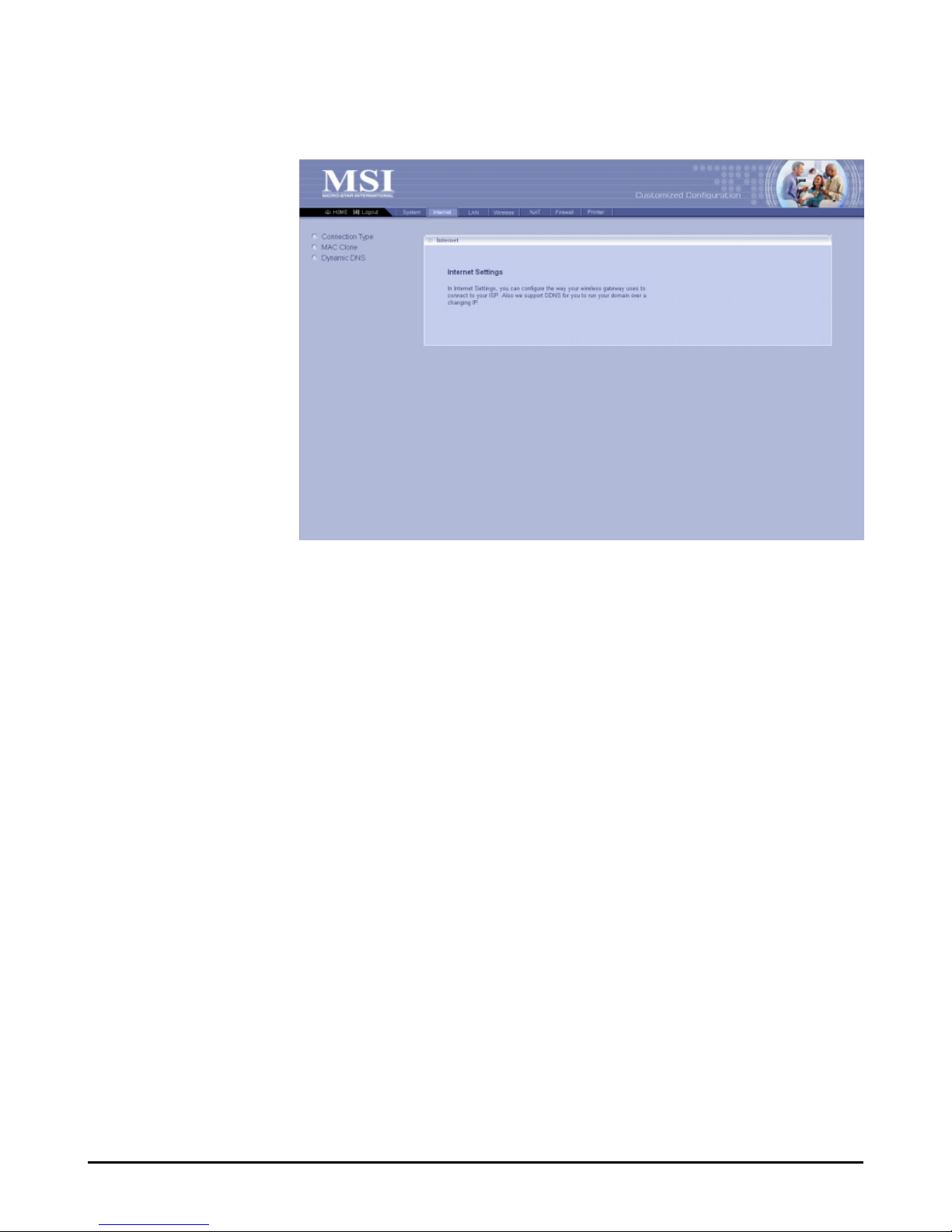
This window includes:
> Connection Type
> MAC Clone
> Dynamic DNS
> Connection Type
This option allows you to configure the way to connect to your
ISP. The wireless gateway can be connected to your ISP in any
of the following ways: DHCP Client, PPPoE, Fixed IP, and
PPTP.
- DHCP Client: If your ISP gives you a host name,
select this option to enter the respective information.
- PPPoE: If you use the xDSL modem to connect to the
ISP, select this option and enter the necessary information, such as the User Name and Password. If your ISP
gives you a service name, you should put it to the related
field.
- Fixed IP: If your ISP assigns a fixed IP Address, select
this option and enter the necessary information, including the IP Address, Subnet Mask, Default Gateway, Primary DNS, and Secondary DNS.
- PPTP: If you use the xDSL modem to connect to the
ISP, select this option and enter the necessary information. (This option is used mostly in Europe.)
Internet
In the Internet settings window, you can configure the way
your wireless gateway used to connect to your ISP.
3.3.2
Page 31
25
> MAC Clone
If your ISP restricts to PCs only, use this function to copy a
PC Media Access Control (MAC) address to your wireless
gateway. This procedure will cause the wireless gateway to
appear as a single PC.
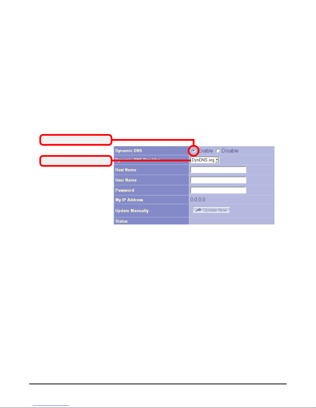
> Dynamic DNS
Setting to Enable allows you to run your domain over a changing
IP. Choose one Dynamic DNS provider from the drop-down
list box and fill in related fields to make it work. If you have
problem in doing these settings, please check with the Dynamic
DNS provider that you choose.
Enable this function
Choose one provider
Page 32
26
LAN
In the LAN settings window, you can configure the IP address
and DHCP server for your wireless gateway.
> IP Setting
You can setup IP address information for the LAN ports of
your gateway.
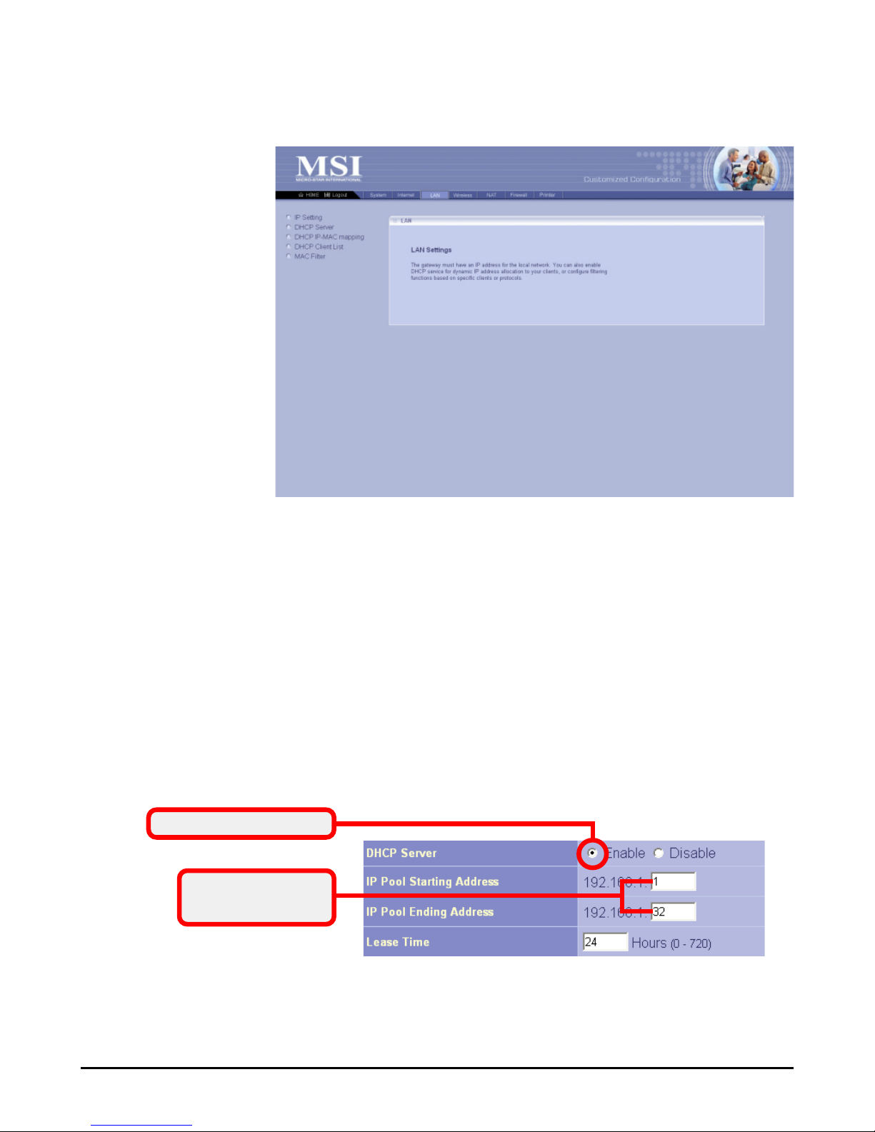
> DHCP Server
Your wireless gateway can act as a DHCP server, and can assign
IP addresses to your clients automatically. The assigned IP
addresses will be within the range of IP pool that you have
specified in this option. For example, not including the default
IP address 192.168.1.254 of the LAN port, you can configure
the range from 192.168.1.1 to 192.168.1.253.
This window includes:
> IP Setting
> DHCP Server
> DHCP IP-MAC mapping
> DHCP Client List
> MAC Filter
> DHCP IP-MAC mapping
You can specify the IP address and hardware address association for a manual binding to a DHCP client.
3.3.3
Enable this function
Enter the range of
IP address
Page 33

27
> DHCP Client List
This option is used to display the DHCP clients assigned by
the DHCP server. Click Refresh to re-load the statistics.
> MAC Filter
This option allows you to limit the computer to access the
Internet. When you enable this option and set up the respective settings, only the computer with a MAC address in the
MAC list can access the Internet.
Page 34
28
Wireless
In this section, you can configure all wireless related settings
for your wireless gateway.
> SSID & Channel
This option is used to set the SSID (Network Name) and channel for your wireless gateway. If you have changed the SSID or
Channel settings, click Apply to save the settings.
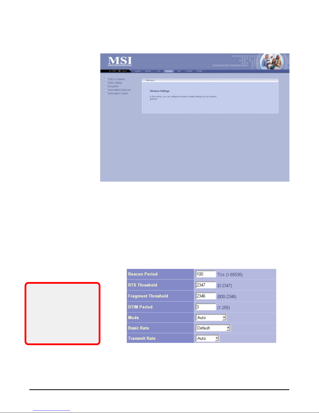
> Radio Setting
This option allows you to configure the operation parameters
of the AP radio settings*.
This window includes:
> SSID & Channel
> Radio Setting
> Encryption
> Associated Client List
> Association Control
* These settings are for
advanced users or MIS
staff only. If you do not
know how to set these
parameters, you are
recommended to use
the default value.
3.3.4
Page 35
29
> Associated Client List
This option is to display information of stations that are currently associating to your wireless gateway.
> Association Control
This option allows you to control which PC can connect to the
wireless LAN. If you enabled this feature, only PCs with
MAC address located in Association Control List can connect
to the wireless LAN.
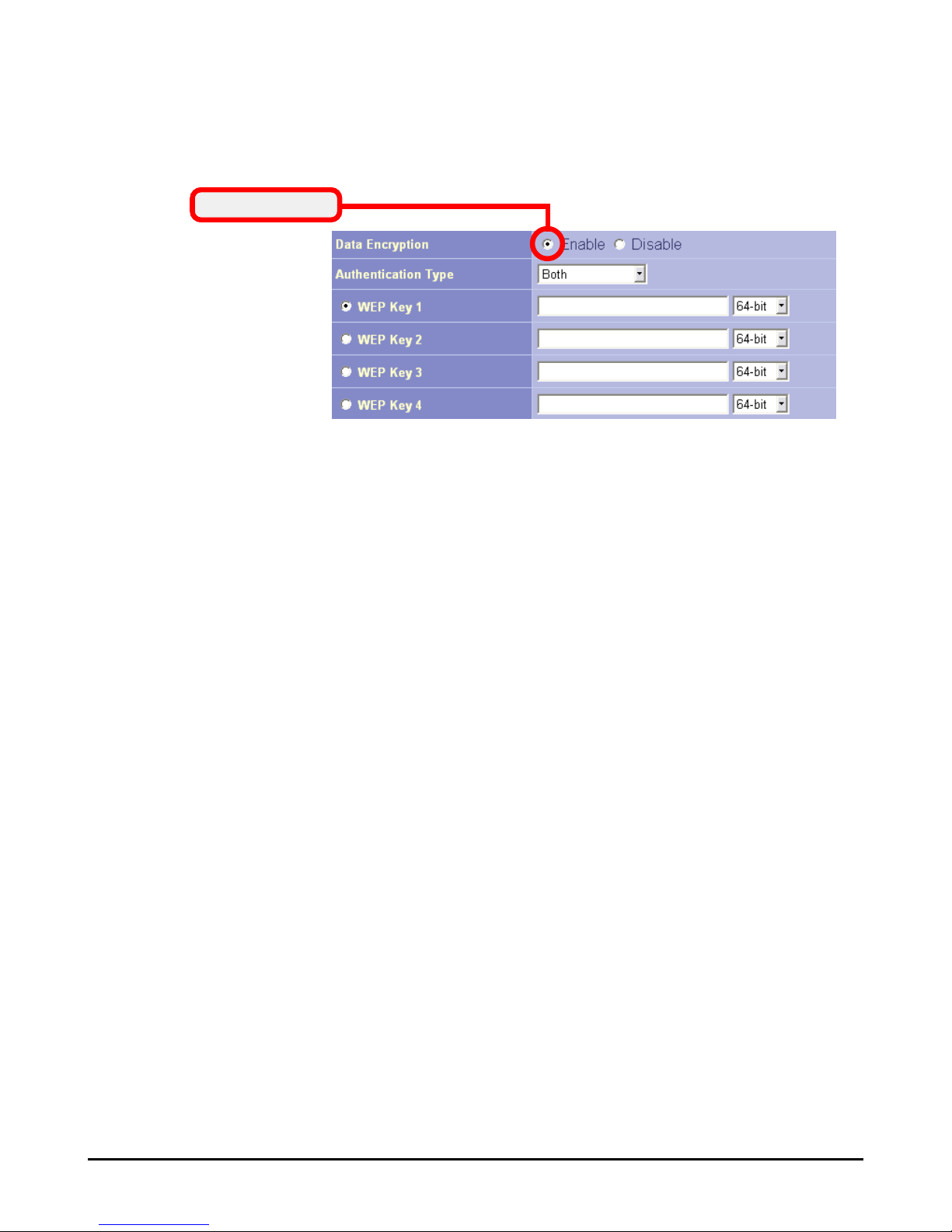
> Encryption
This option allows you to configure the setting of data
encryption. The WEP key must be set before the data encryption is enforced.
Enable WEP
Page 36
30
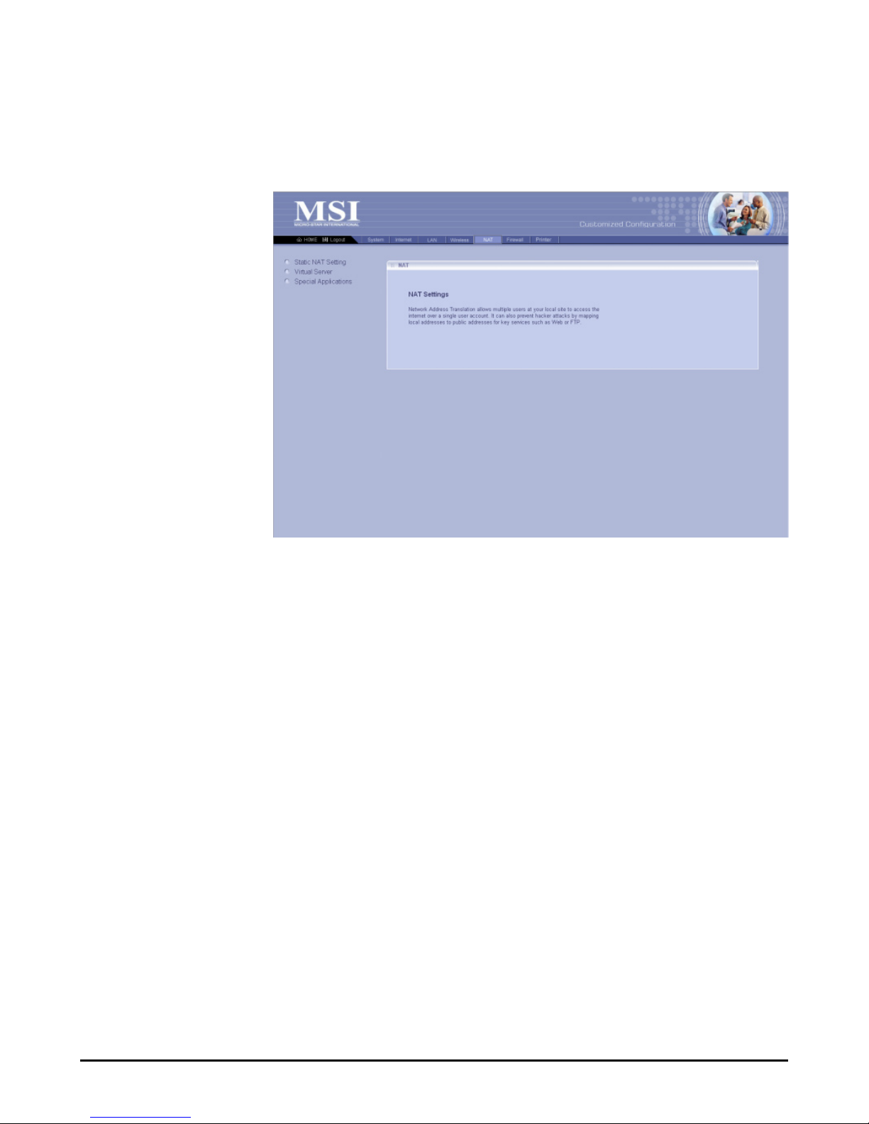
NAT
NAT (Network Address Translation) allows multiple users at
your local site to access the Internet over a single-user account.
It can also prevent hacker attacks by mapping local addresses
to public addresses for key services, such as Web or FTP.
> Static NAT Setting
Use the Static NAT screen for the Network Address Translation
(NAT) process that provides internal to external IP address
mapping. It also includes a list of Global IP if you have setup.
> Virtual Server
You can configure the wireless gateway as a virtual server, so
that remote users can access the services (e.g. Web or FTP) at
your local site via public IP addresses. It also includes a list of
Virtual Server if you have setup (maximum 32 entries).
> Special Applications
Some special applications, such as Internet gaming, video conference and Internet telephony, require multiple connections.
This feature allows these applications to work properly. It
also includes a list of Special Applications if you have setup
(maximum 32 entries).
This window includes:
> Static NAT Setting
> Virtual Server
> Special Applications
3.3.5
Page 37
31
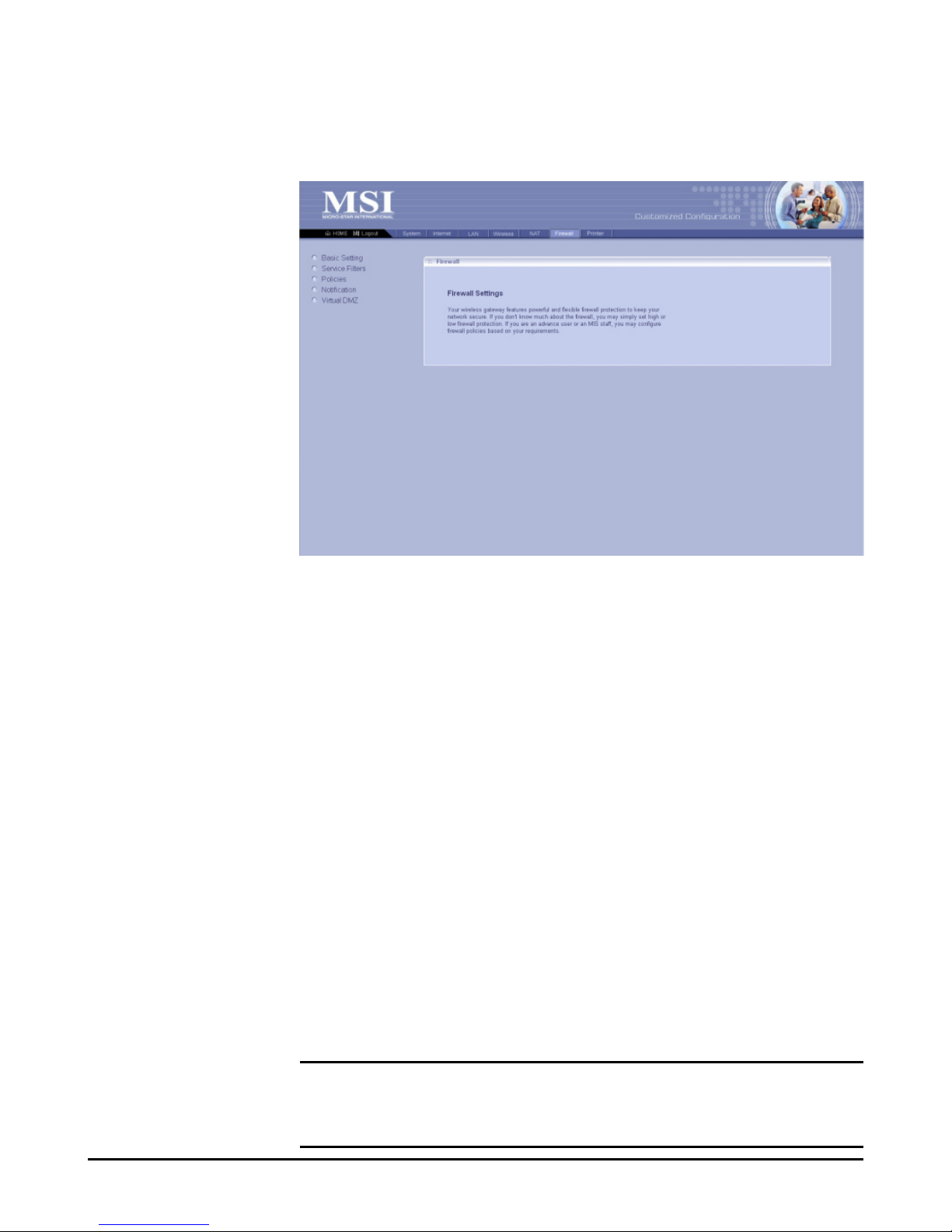
Firewall
The wireless gateway provides extensive firewall protection
by restricting connection parameters to eliminate the risk of
hacker attacks.
This window includes:
> Basic Setting
> Service Filters
> Policies
> Notification
> Virtual DMZ
> Basic Setting
You can set up the level of firewall protection in this option.
For general use, the user can just configure the firewall through
the Firewall Protection option (High, Low, and Disable), which
include pre-defined configuration for the respective options.
For advanced settings, please ask the network manager for assistance.
> Service Filters
You can use this window to create and apply filters that can
selectively block traffic to pass in and out of your network
according to Protocol Type or Port Number. It also includes a
list of Filters if you have setup (maximum 32 entries).
> Policies
Policies are the core of your firewall configuration. You may
define and schedule your rules for inbound/outbound traffic.
IMPORTANT: Any incorrect setting in this option may cause the gateway malfunctioned. If you are not sure of the settings, please ask the
network manager for help.
3.3.6
Page 38

32
> Notification
You can enable Email Notification function. Once enabled, you
should configure the respective settings in the following fields.
This is a useful feature when you want to acquire the security
log remotely.
> Virtual DMZ
If you have a local client PC that cannot run an Internet application properly from behind the NAT firewall, you can open
the client up to unrestricted two-way Internet access by defining a virtual DMZ. It also includes a list of DMZ if you have
setup.
Page 39
33
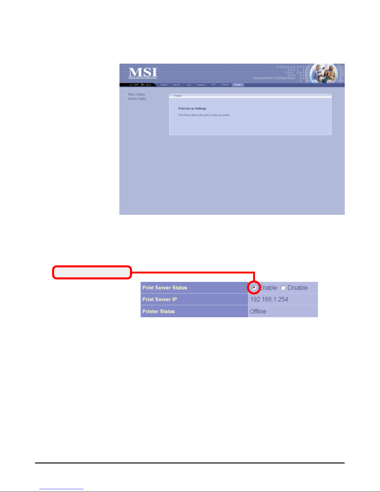
Printer
You can configure the print server settings in this window.
This function allows the LAN users to share one printer.
This window includes:
> Basic Setting
> Monitor Status
> Basic Setting
This option allows you to configure the settings of the Print
Server to share the printing service for LAN users.
> Monitor Status
This option displays the information of the current printing
tasks.
Enable Print Server
3.3.7
Page 40

34
Page 41
35
Using the Print Server
The RG54GS provides a USB port to connect the USB printer,
allowing you to built up a print server in your network easily
and quickly. This chapter is to help you set up the LPD client
on your PC.
NOTE: The settings or values in the following diagrams are FOR YOUR
REFERENCE ONLY. The actual settings and values depend on your
system.
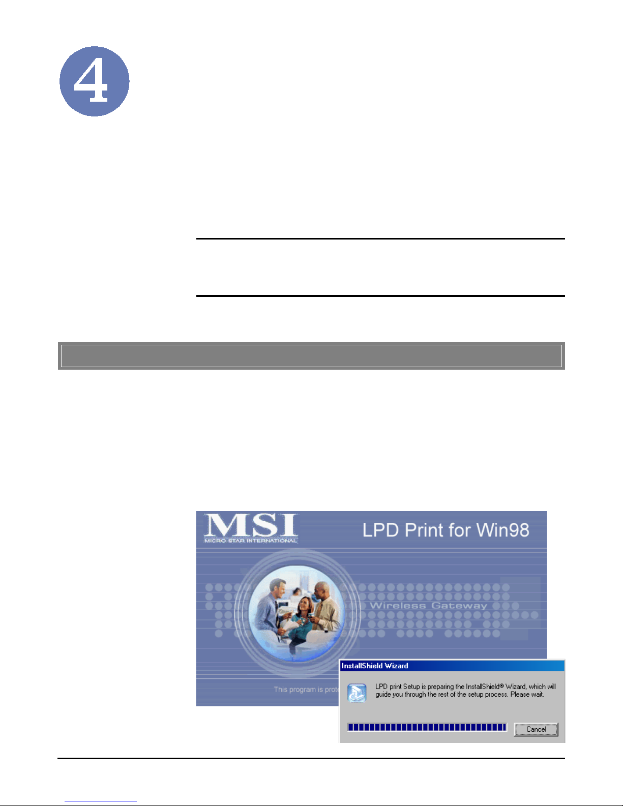
Installing the LPD Client Utility
For Windows 98SE/ME user, the LPD client utility should be
installed in the computer before adding a printer.
1. Double-click the D:\PrinterDriver\Setup.exe in the
software CD to launch the setup program, where D is
the disk drive.
>>> 4.1 For Windows 98SE/ME User
4.1.1
Page 42
36
2. In the Welcome screen of the InstallShield Wizard,
click Next.
3. Read the License Agreement, and click Yes.
4. In the following screen, click Next to start copying
files.
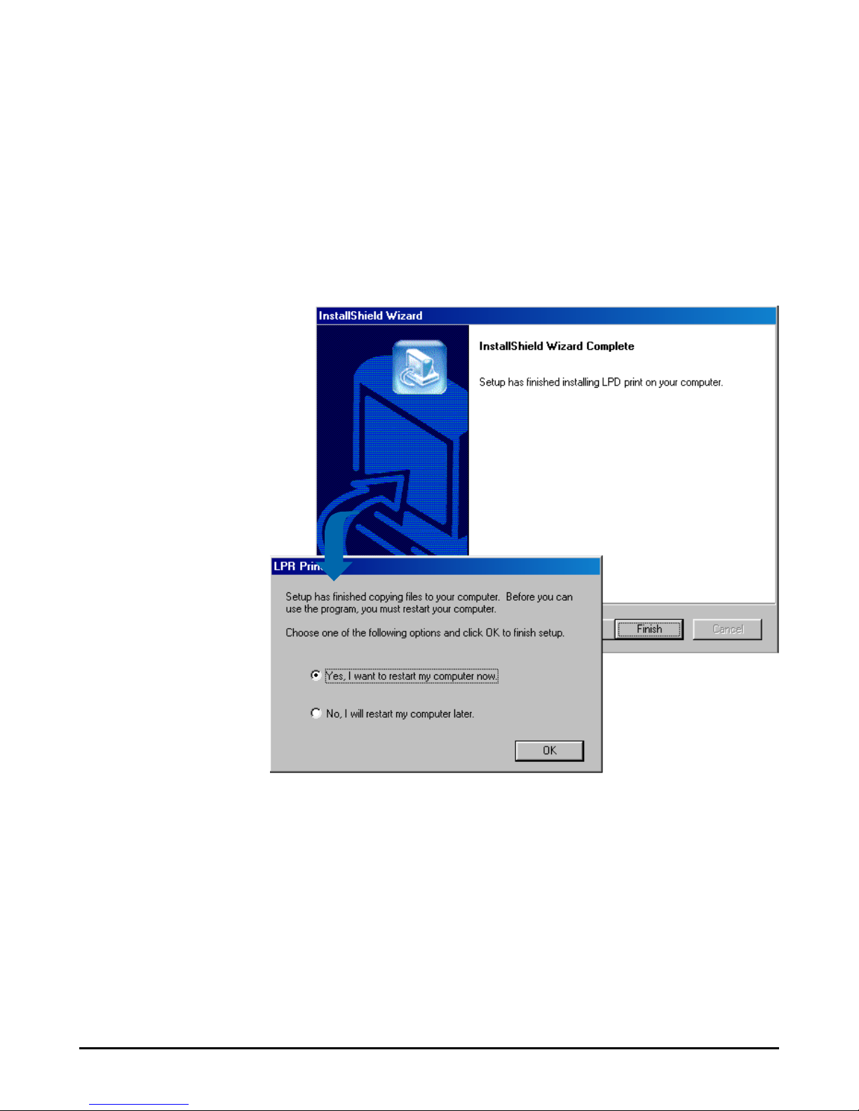
5. When completed, click Finish. Then, choose the Yes, I
want to restart my computer now option and click OK to
restart your computer.
Then, you can install the driver for the printer connected
to the gateway.
Page 43
37
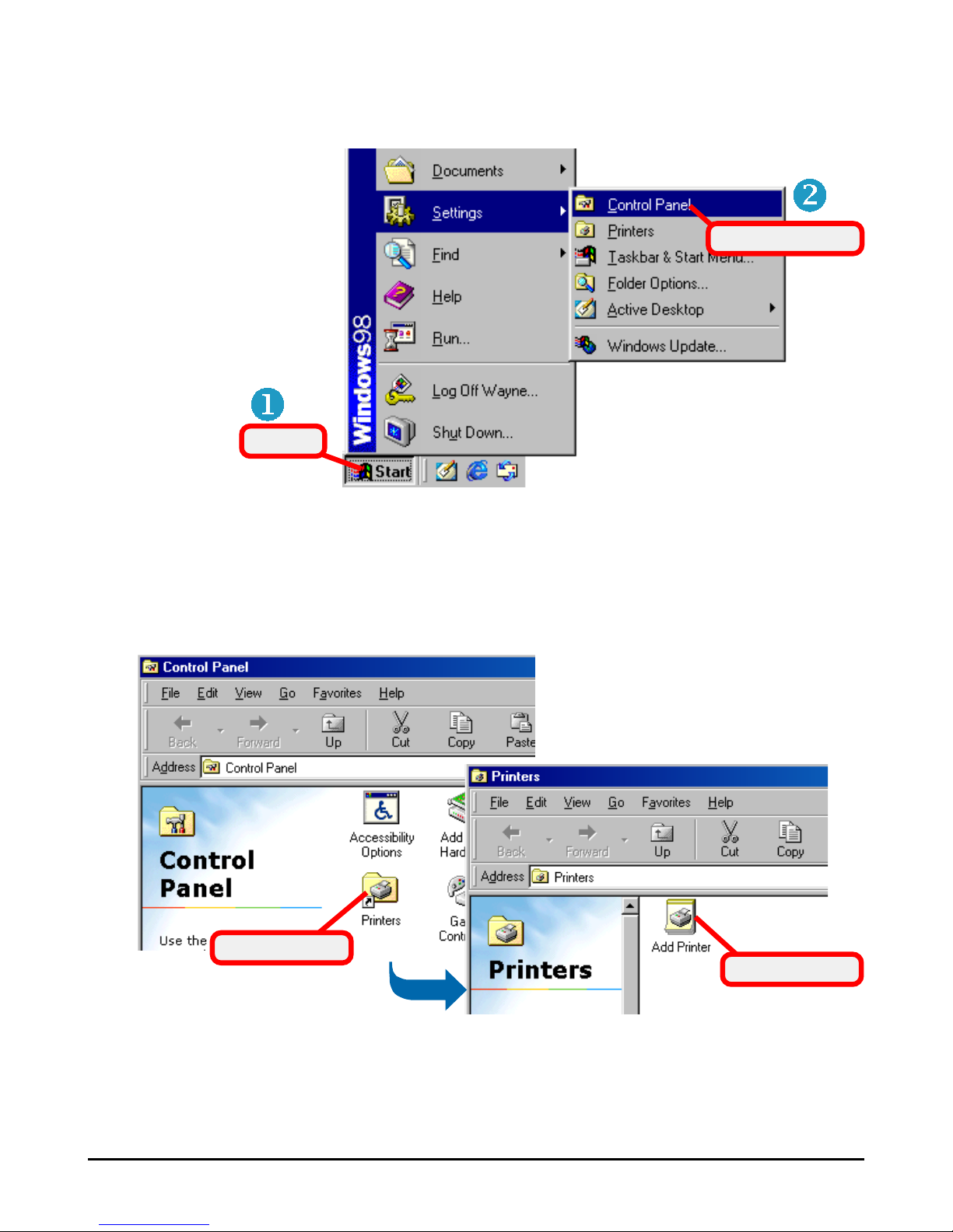
2. In the Control Panel window, double-click the
Printers icon. Then, in the Printers window, doubleclick the Add Printer icon to launch the Adding Printer
Wizard.
Click
Select this item
Installing the Printer Driver
1. Click Start and choose Settings, then Control Panel.
4.1.2
Double-click
Double-click
Page 44
38
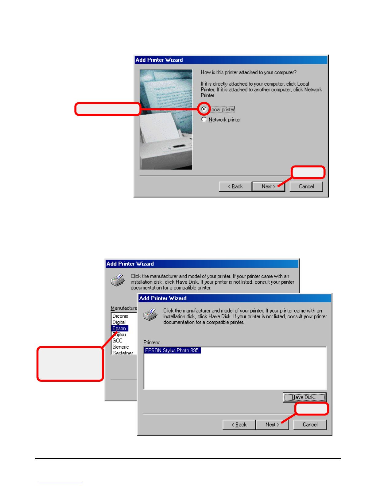
3. In Adding Printer Wizard, click Next, and then select
Local printer and click Next.
Select this option
4. Select the appropriate Manufacturer and Printer type
from the lists to install the driver. Otherwise, click Have
disk... to find the driver in specified location. Then,
select the correct printer from the lists and click Next.
Select the correct
printer connected
to the gateway.
Click
Click
Page 45
39
5. In the following windows, select the printer port and
enter the printer name.
6. When completed, click OK.
Now, you have added the printer successfully.
NOTE: For some printers of specified manufacturer, you may need to
connect the printer to the computer to install the driver. In this case,
connect the printer to the computer and install the driver first, and then
remove the printer to connect it to the gateway.
Configuring the LPD Port
Before configuring the LPD port, connect your computer to
the gateway first.
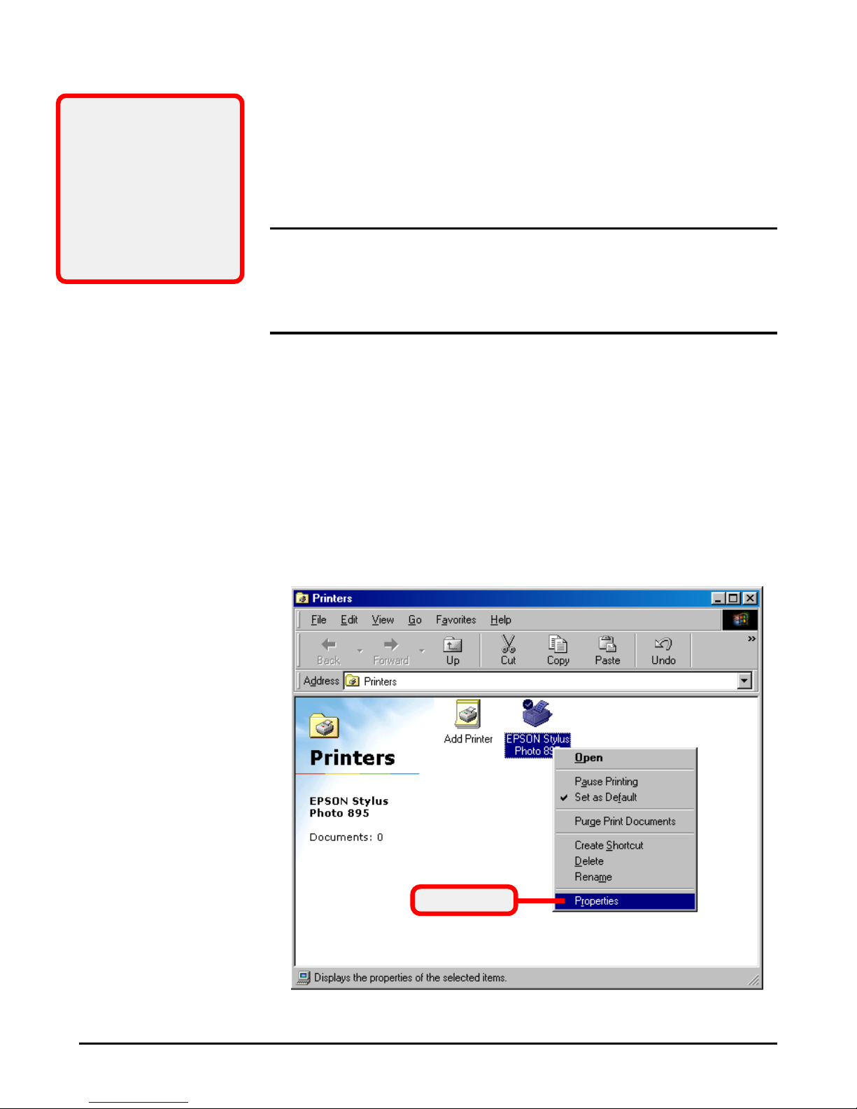
1. Open the Control Panel window, then the Printers
window. In the Printers window, right-click the
printer icon you added in the previous section, and
select Properties.
4.1.3
Tip: At step 5, you can
assign any port to this
printer, such as LPT1
(Windows default
setting), and then
configure the LPD port
later (see the following
section).
Select this
Page 46
40
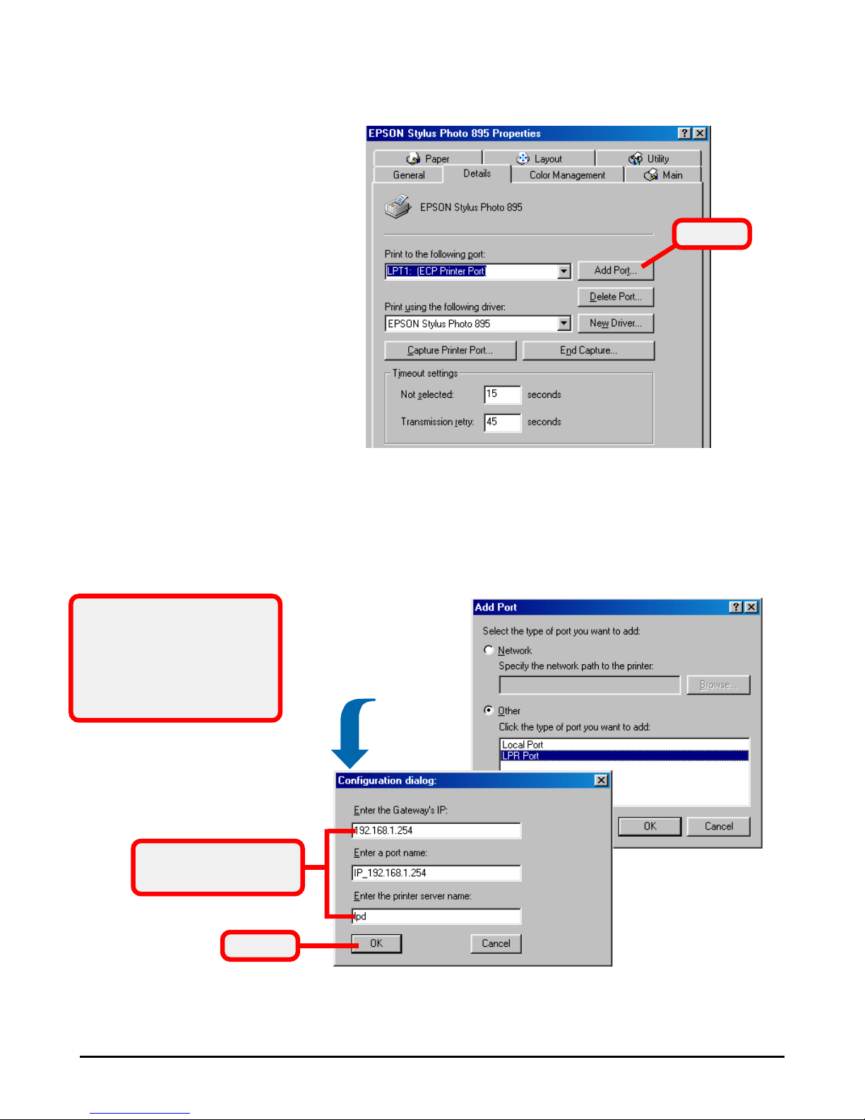
2. The printer’s Properties window appears. Select the
Details tab, and click Add port....
Click
3. In the Add Port window, select Other option and then
LPR Port; then, click OK to enter the printer’s
information. When completed, click OK to return to the
printer’s Properties window.
Click
Enter the printer’s
information
The port name can be any
one you like; however, the
Gateway’s IP address
MUST be identical to the
setting on your gateway.
Page 47
41
4. The port you added will appear in the list, please click
Apply and then OK to complete the installation.
5. Anytime you want to configure the LPD port, select
the port from the list and click Port Settings.... The
Configuration dialog window will appear allowing
you to change the settings.
After clicking OK to finish configuring, you must click
Capture printer port to update the port you modified.
Finally, click OK to complete the installation.
Installing the Printer Driver
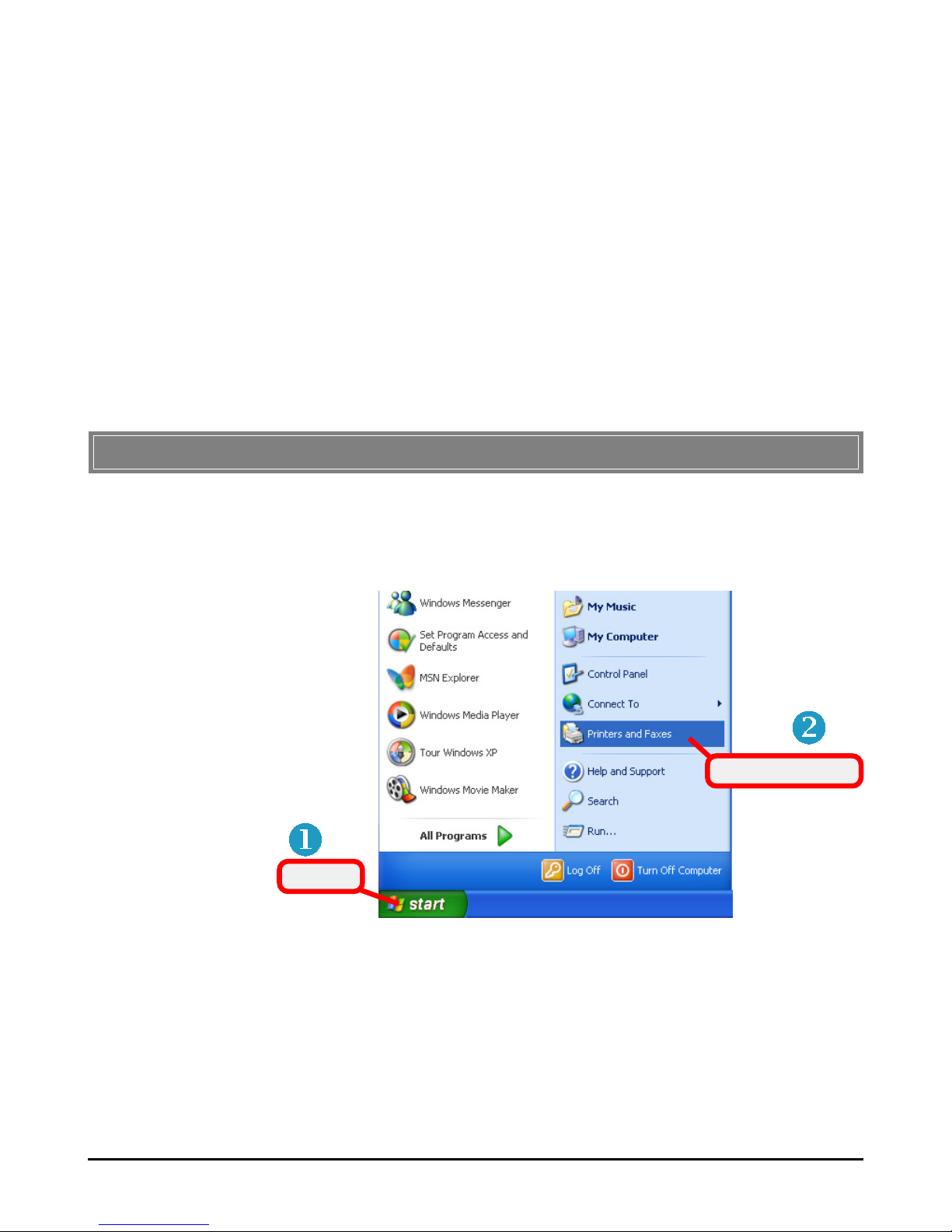
1. Click Start and choose Printers and Faxes.
>>> 4.2 For Windows 2000/XP User
4.2.1
Click
Select this item
Page 48
42
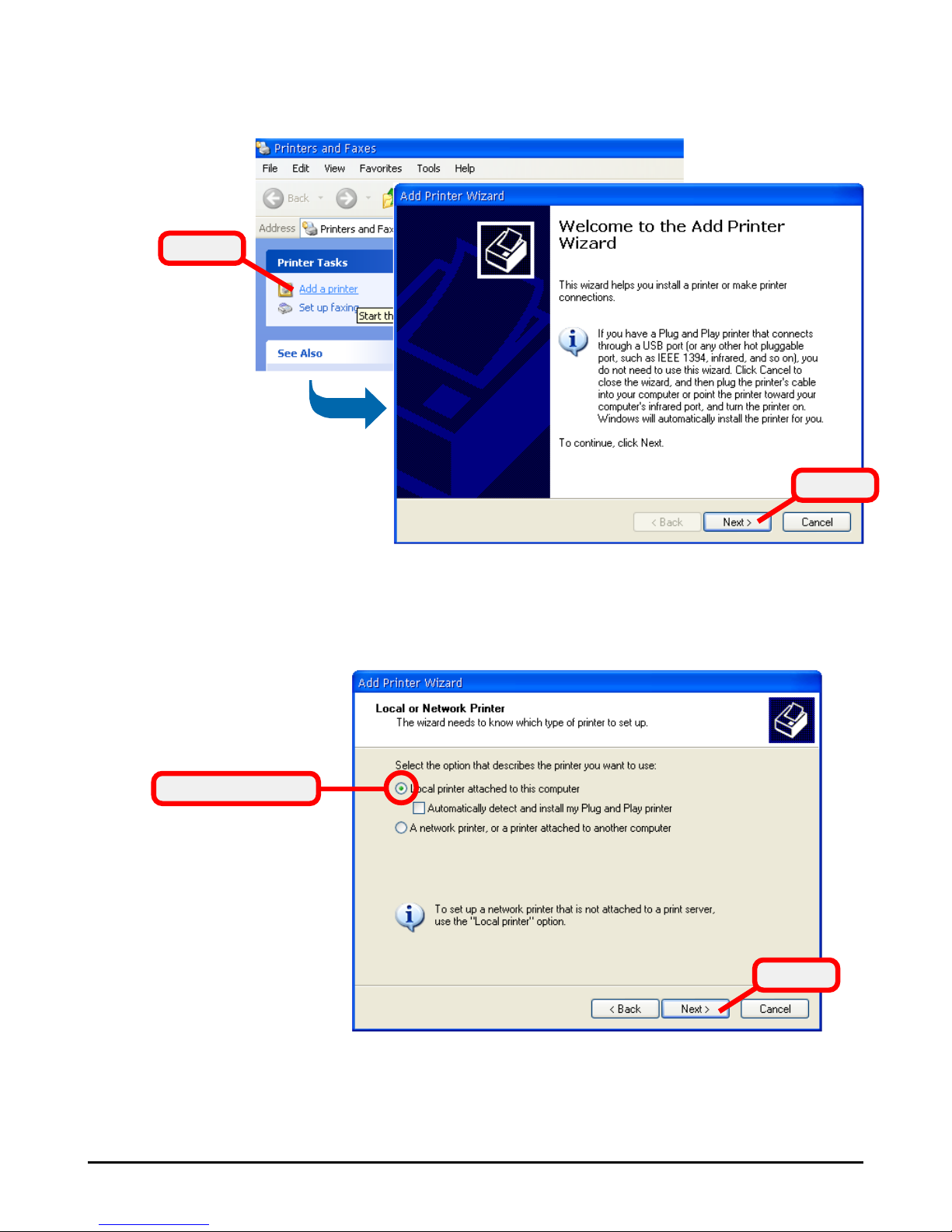
2. Click Add Printer, and then click Next in the Adding
Printer Wizard window.
Click
Click
3. Select Local printer attached to this computer and
click Next.
Click
Select this option
Page 49
43
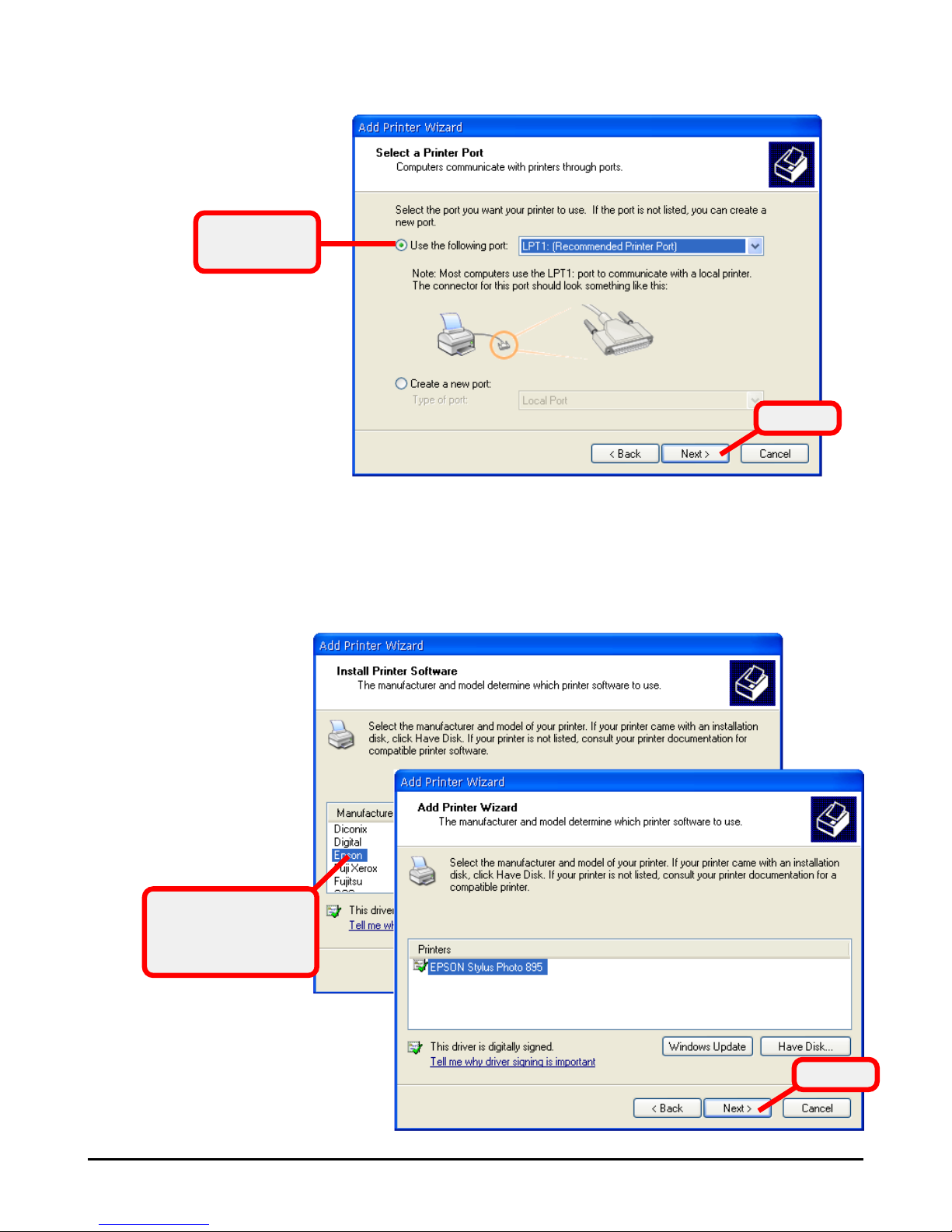
5. Select the appropriate Manufacturer and Printers from
the lists to install the driver. Otherwise, click Have
disk... to find the driver in specified location. Then,
select the correct printer from the lists and click Next.
Select the correct
printer connected
to the gateway.
4. Select LPT1 and click Next.
Select LPT1
in this field.
Click
Click
Page 50
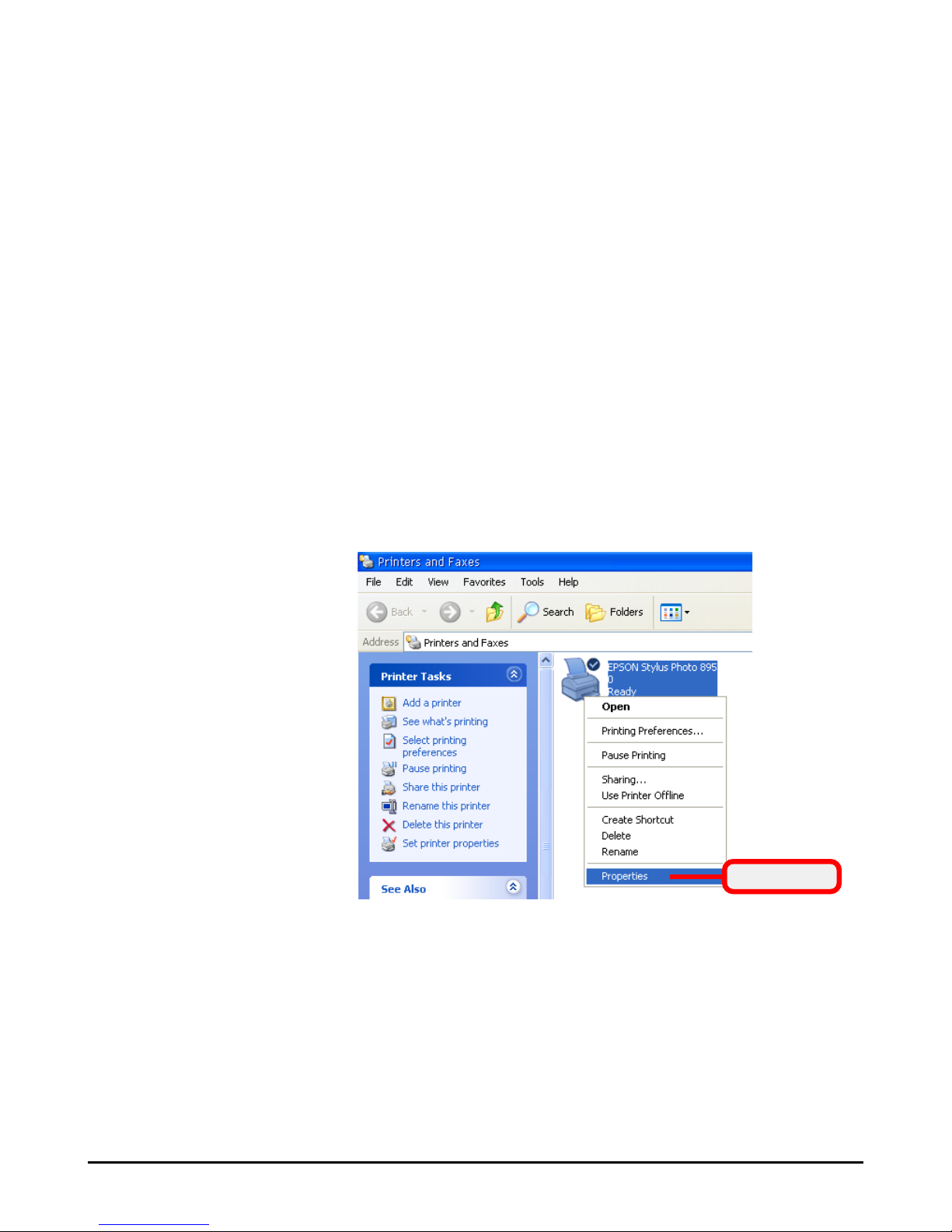
44
Select this
Configuring the LPD Port
Before configuring the LPD port, connect your computer to
the gateway first.
1. Open the Control Panel window, then the Printers
and Faxes window. In the Printers and Faxes
window, right-click the printer icon you added and
select Properties.
4.2.2
6. Enter a name for this printer, and click Next.
7. In Print Test Page, choose No to skip the print test, and
click Next.
8. When completed, click Finish and the setup program
start to copy files to your system.
Now, you have added the printer successfully.
Page 51
45
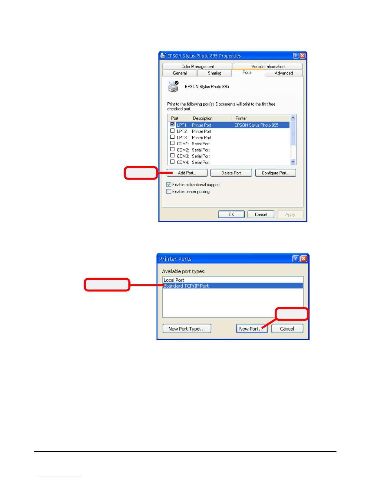
2. The printer’s Properties window appears. Select the
Ports tab, and click Add port....
Click
3. Select Standard TCP/IP Port and click New Port....
4. In the Welcome screen of Add Standard TCP/IP Printer
Port Wizard, click Next.
Select this
Click
Page 52
46
Click
Select this
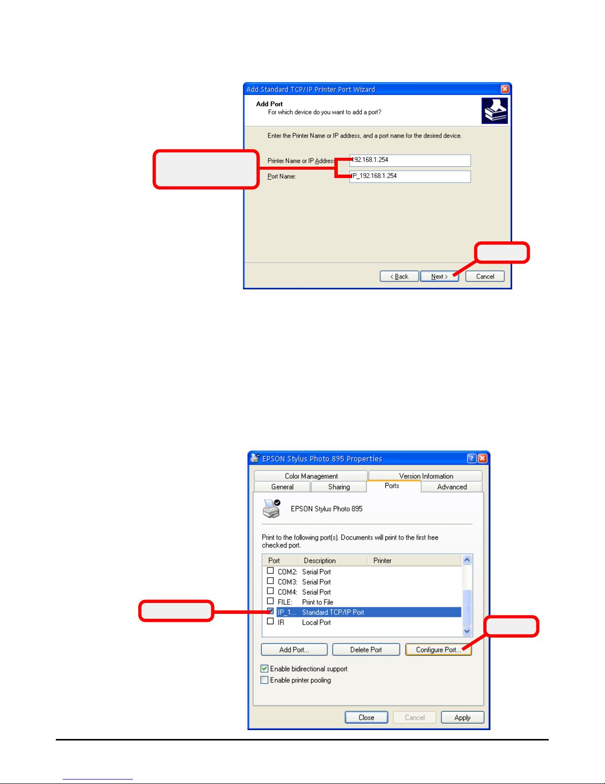
5. Enter the Printer Name (or IP Address) and Port Name,
and click Next.
Enter the printer’s
information
6. Select Device Type and click Next.
7. When completed, click Finish. You have added the
Standard TCP/IP Port successfully. Click Close to
return to the printer’s Properties window, and new
Standard TCP/IP Port will appear in the list.
8. Select the Standard TCP/IP Port and click Configure
Port....
Click
Page 53
47
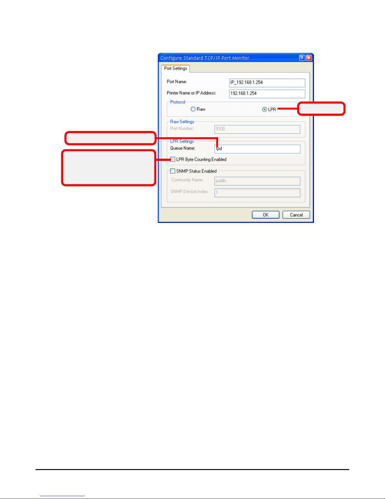
9. Select LPR protocol and then enter Queue Name,
and then click OK to complete the configuration.
Enter the Queue Name
You can check this option
to monitor the progress of
printer’s task.
Select this
Page 54

48
Page 55
49
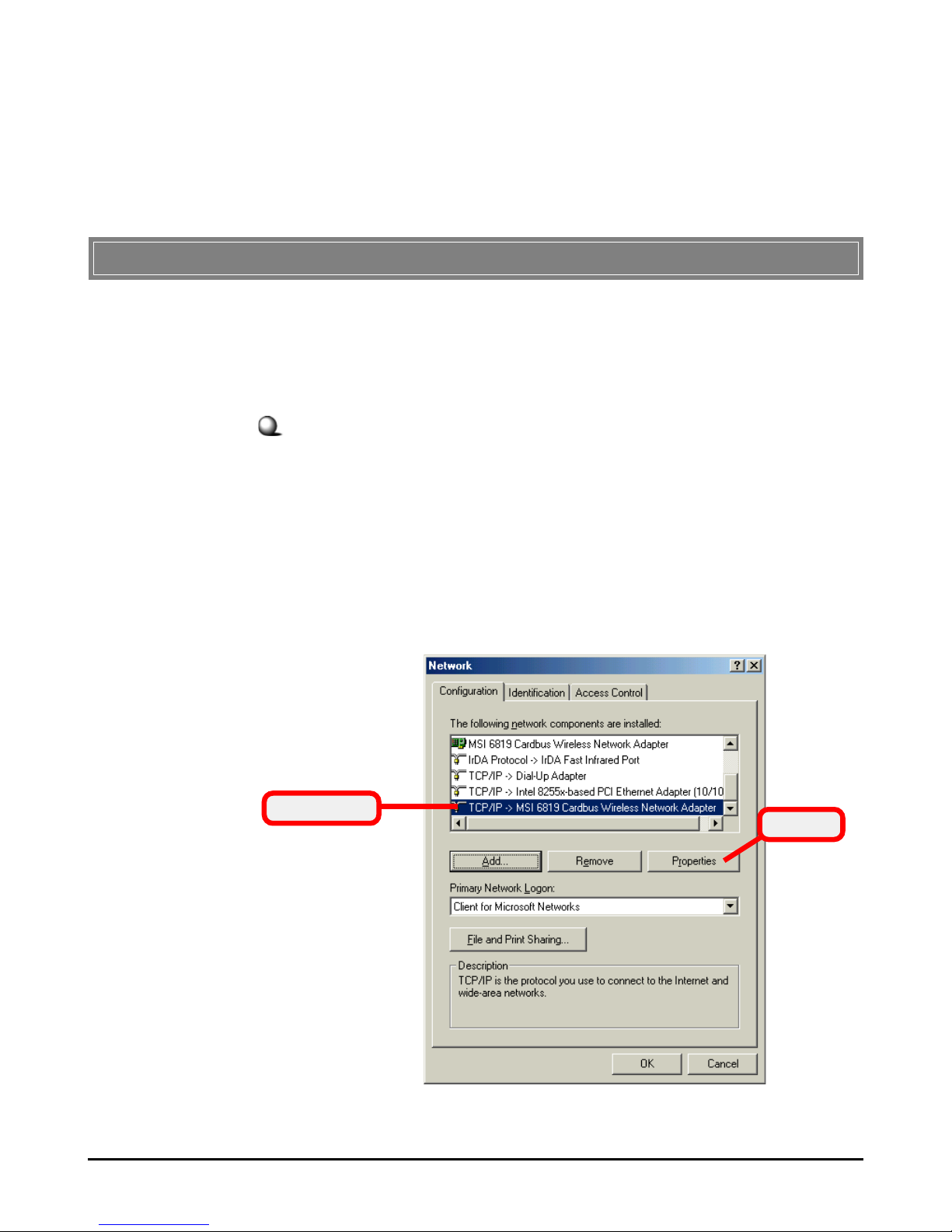
To configure the RG54GS, you will need to assign a fixed IP
address to this computer within the IP address range of the
RG54GS.
Under Windows 98SE/ME
1. Go to Start -> Settings -> Control Panel.
2. Double-click the Network icon.
3. The Network window appears as below. Select the
TCP/IP item, and click Properties to bring up the
TCP/IP Properties window.
Appendix A - Assigning a Fixed IP Address
Appendix
Select this
Click
Page 56
50
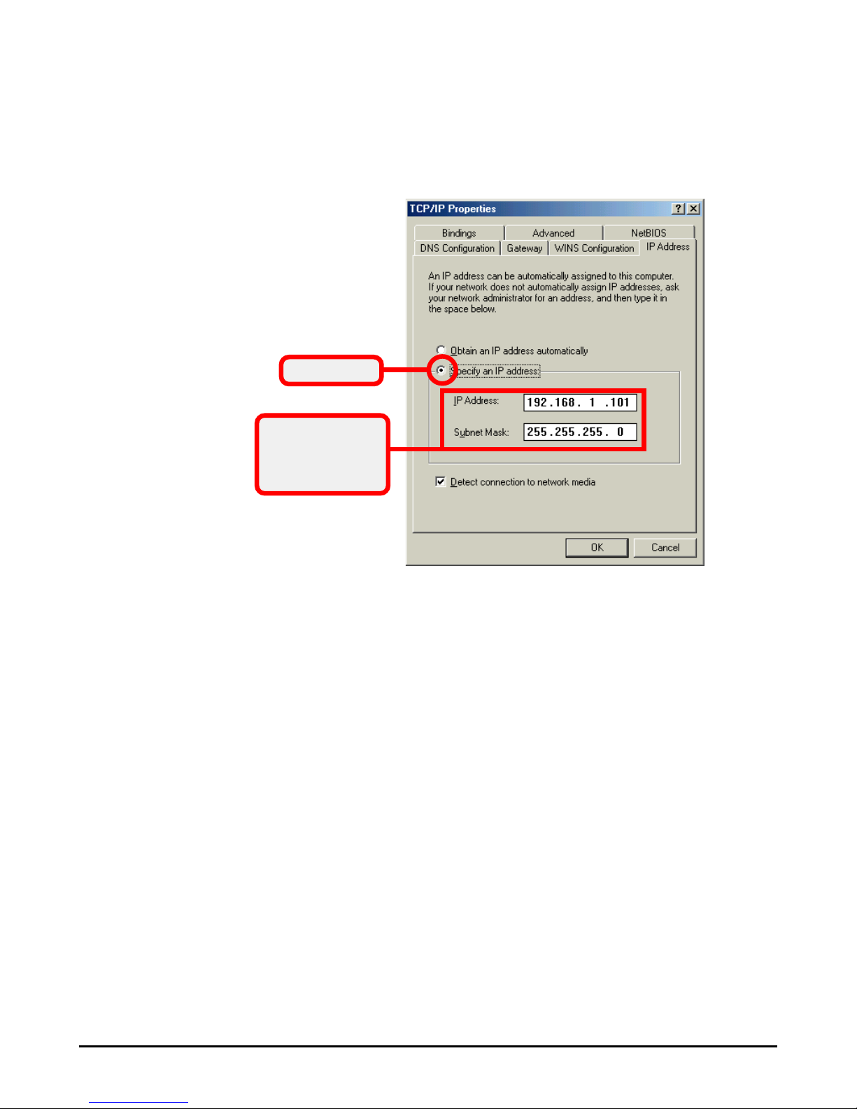
4. Choose the IP Address tab and check the Specify an
IP Address option. Then, enter an IP address into the
empty field. Suggested IP Address Range is 192.168.
1.1 to 192.168.1.253, and suggested Subnet Mask is
255.255.255.0.
5. Click OK. Then, click Yes when prompted to reboot
the computer.
Enter a fixed IP
address and
Subnet Mask
Check this
Page 57
51
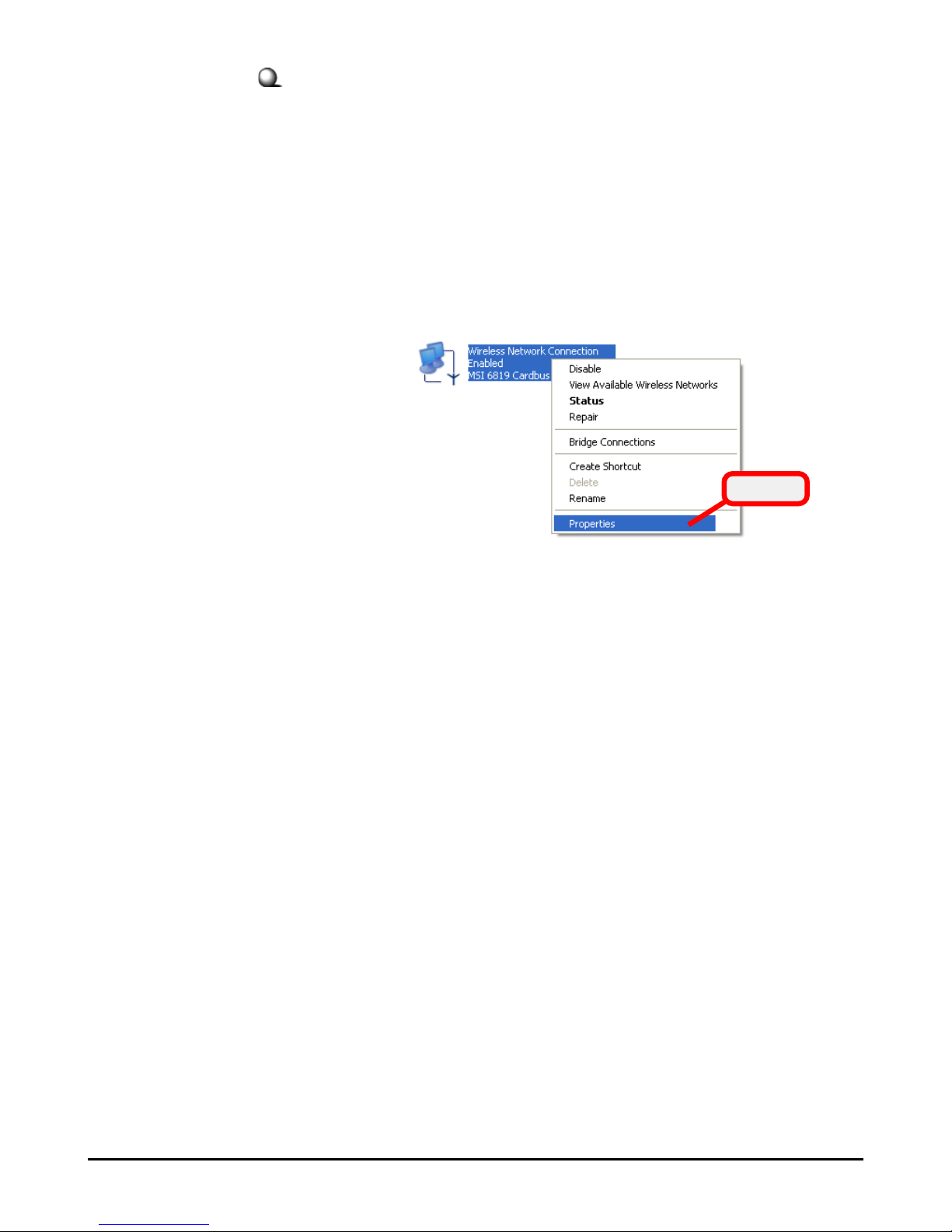
Under Windows 2000/XP
1. Click Start and choose Control Panel to open the
Control Panel window.
2. Double-click the Network Connection icon to open
the Network Connection window.
3. Right-click the Network Adapter icon and click
Properties from the shortcut menu.
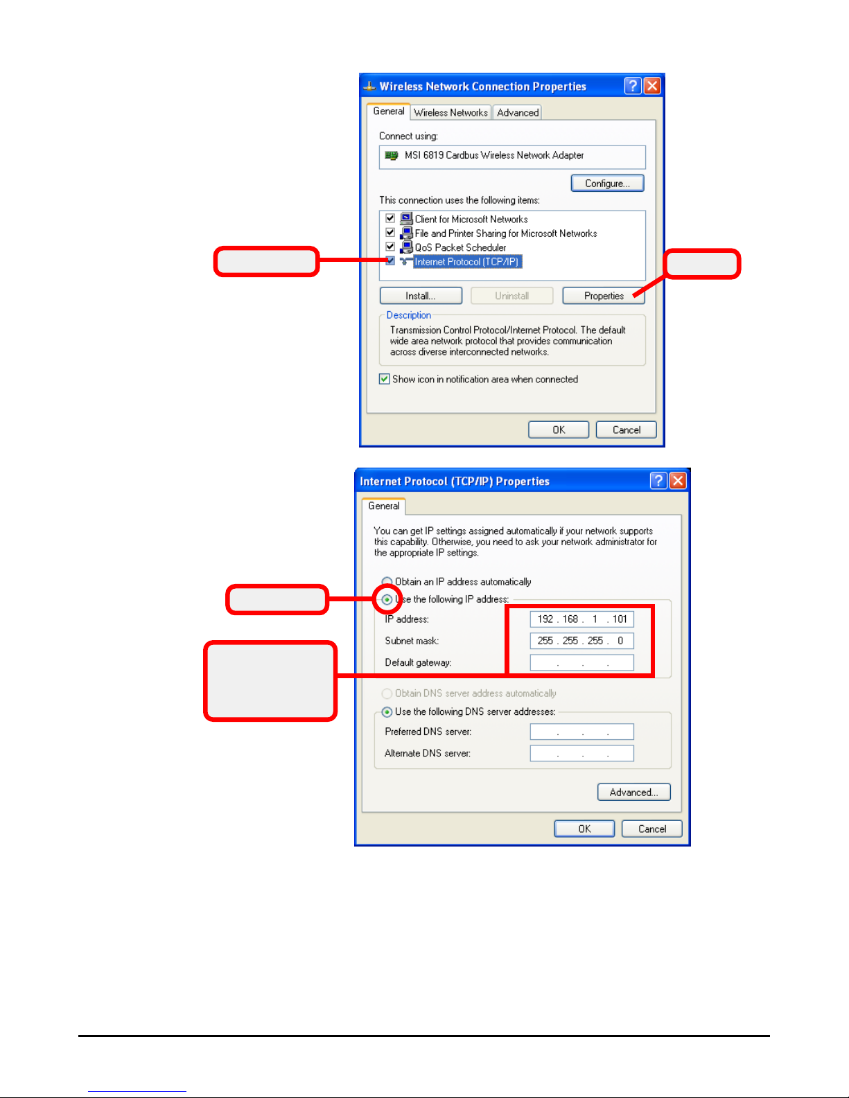
4. When the Connection Properties window appears,
choose the General tab and select Internet
Protocol [TCP/IP], and click Properties to bring up
the Internet Protocol [TCP/IP] Properties
window.
5. Check Use the following IP address. Then, enter
an IP address into the empty field. Suggested IP
Address Range is 192.168.1.1 to 192.168.1.253, and
suggested Subnet Mask is 255.255.255.0.
Click
Page 58
52
6. Click OK to complete the configuration.
Configuring a fixed IP address
Click
Select this
Enter a fixed IP
address and
Subnet Mask
Check this
Page 59
53
The RG54GS allows you to upgrade its firmware conveniently
from the Configuration Utility. It means that you can obtain
the latest function and take most advantage of your RG54GS.
However, there is some risk when your are upgrading firmware,
such as power failure. If, unfortunately, power failure occurs
during upgrading firmware, the RG54GS may not work anymore.
To protect your investment, MSI provides a second way to
resume the gateway’s original firmware before upgrading, and
keep the gateway working normally.
To resume the firmware:
1. Connect the gateway to a computer, and then connect
the power cable. Assign a fixed IP address to this
computer within the IP address range of the gateway.
(See Appendix A for detail instruction.)
2. Click Start at the taskbar and select Run.
3. If you are using Window 2000/XP operating system,
type cmd in the Open box and press [Enter]. (For
Windows 98SE/ME, you should type command.)
4. Type tftp -i [host IP address] put [source]* in the
pop-up DOS window and press [Enter].
5. Wait for a few seconds, and the original firmware will
be re-loaded into the gateway. Then, you can enter
the Configuration Utility and use the gateway again.
* host IP address - the
gateway’s IP address,
such as 192.168.1.254.
source - the path and
filename of the firmware,
such as D:\RG54GS.gzh.
Appendix B - Resuming the Previous Firmware
Tip: Type tftp and press
[Enter] in the DOS
window can bring up the
respective instruction
for its parameter.
 Loading...