

Page 1
i
Version 1.1
G52-M6799X4
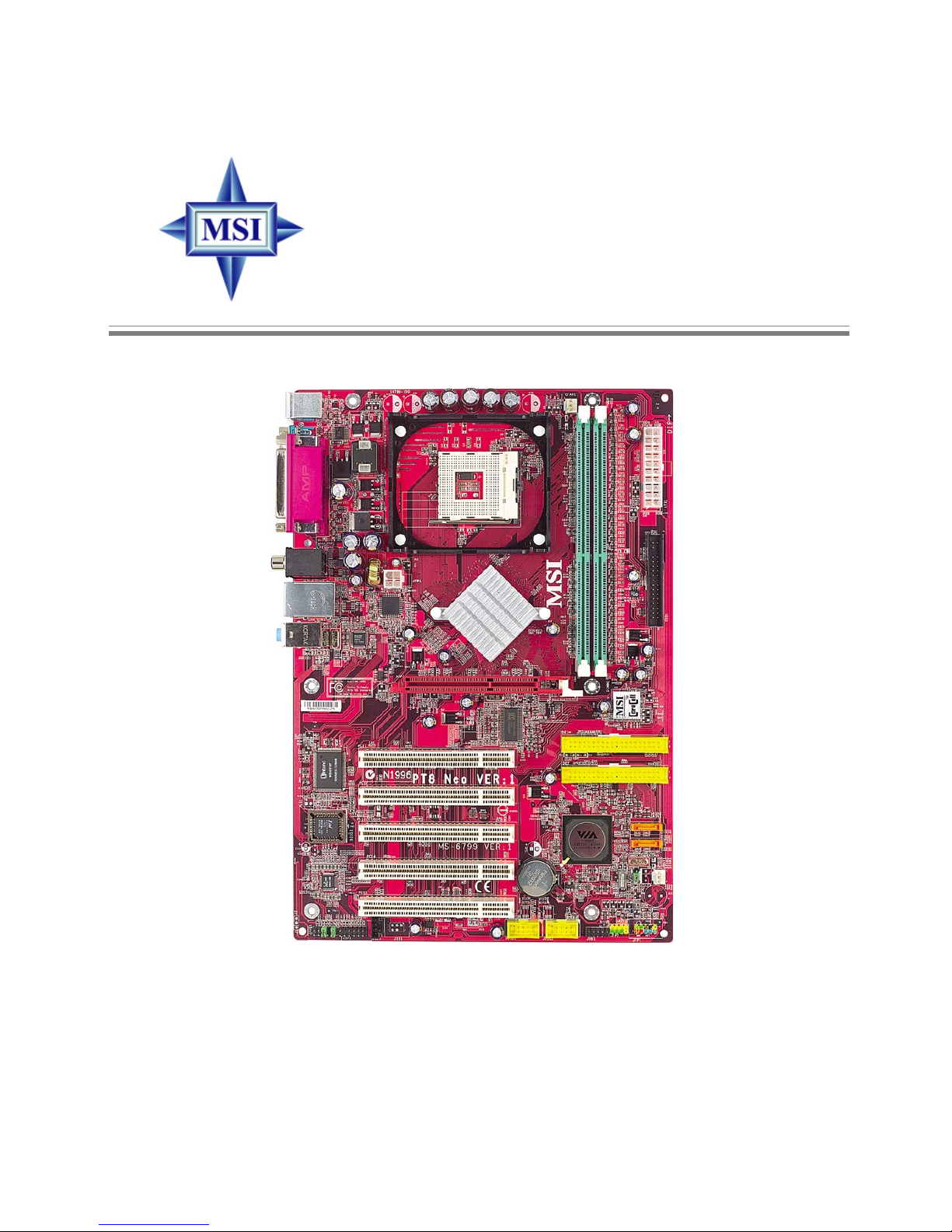
MS-6799 (v1.X) ATX Mainboard
PT8 Neo Series
Page 2
ii
Manual Rev: 1.1
Release Date: Nov. 2003
FCC-B Radio Frequency Interference Statement
This equipment has been tested and found to comply with the limits for a class
B digital device, pursuant to part 15 of the FCC rules. These limits are designed
to provide reasonable protection against harmful interference when the equipment is operated in a commercial environment. This equipment generates, uses
and can radiate radio frequency energy and, if not installed and used in accordance with the instruction manual, may cause harmful interference to radio
communications. Operation of this equipment in a residential area is likely to
cause harmful interference, in which case the user will be required to correct
the interference at his own expense.
Notice 1
The changes or modifications not expressly approved by the party responsible for compliance could void the user’s authority to operate the equipment.
Notice 2
Shielded interface cables and A.C. power cord, if any, must be used in order to
comply with the emission limits.
VOIR LA NOTICE D’INSTALLATION AVANT DE RACCORDER AU
RESEAU.
Micro-Star International MS-6799
Tested to comply
with FCC Standard
For Home or Office Use
Page 3

iii
Copyright Notice
The material in this document is the intellectual property of MICRO-STAR
INTERNATIONAL. We take every care in the preparation of this document,
but no guarantee is given as to the correctness of its contents. Our products
are under continual improvement and we reserve the right to make changes
without notice.
Trademarks
All trademarks are the properties of their respective owners.
Intel® and Pentium® are registered trademarks of Intel Corporation.
AMD, Athlon™, Athlon™ XP, Thoroughbred™, and Duron™ are registered
trademarks of AMD Corporation.
PS/2 and OS®/2 are registered trademarks of International Business Machines
Corporation.
Windows® 95/98/2000/NT/XP are registered trademarks of Microsoft
Corporation.
Netware® is a registered trademark of Novell, Inc.
Award® is a registered trademark of Phoenix Technologies Ltd.
AMI® is a registered trademark of American Megatrends Inc.
Revision History
Revision Revision History Date
V1.0 First release for PCB 1.X Sep. 2003
V1.1 Second release for PCB 1.X Nov. 2003
Technical Support
If a problem arises with your system and no solution can be obtained from the
user’s manual, please contact your place of purchase or local distributor.
Alternatively, please try the following help resources for further guidance.
h Visit the MSI website for FAQ, technical guide, BIOS updates, driver
updates, and other information: http://www.msi.com.tw/
h Contact our technical staff at: [email protected]
Page 4

iv
1. Always read the safety instructions carefully.
2. Keep this User’s Manual for future reference.
3. Keep this equipment away from humidity.
4. Lay this equipment on a reliable flat surface before setting it up.
5. The openings on the enclosure are for air convection hence protects the
equipment from overheating. DO NOT COVER THE OPENINGS.
6. Make sure the voltage of the power source and adjust properly 110/220V
before connecting the equipment to the power inlet.
7. Place the power cord such a way that people can not step on it. Do not
place anything over the power cord.
8. Always Unplug the Power Cord before inserting any add-on card or module.
9. All cautions and warnings on the equipment should be noted.
10. Never pour any liquid into the opening that could damage or cause electrical shock.
11. If any of the following situations arises, get the equipment checked by a
service personnel:
z The power cord or plug is damaged.
z Liquid has penetrated into the equipment.
z The equipment has been exposed to moisture.
z The equipment has not work well or you can not get it work according
to User’s Manual.
z The equipment has dropped and damaged.
z The equipment has obvious sign of breakage.
12. DO NOT LEAVE THIS EQUIPMENT IN AN ENVIRONMENT
UNCONDITIONED, STORAGE TEMPERATURE ABOVE 600 C (1400F), IT
MAY DAMAGE THE EQUIPMENT.
Safety Instructions
CAUTION: Danger of explosion if battery is incorrectly replaced.
Replace only with the same or equivalent type recommended by the
manufacturer.
Page 5

v
CONTENTS
FCC-B Radio Frequency Interference Statement .......................................... iii
Copyright Notice .......................................................................................... iii
Revision History ........................................................................................... iii
Technical Support ......................................................................................... iii
Safety Instructions .......................................................................................iv
Chapter 1. Getting Started ........................................................................ 1-1
Mainboard Specifications .................................................................... 1-2
Mainboard Layout ............................................................................... 1-4
MSI Special Features ........................................................................... 1-5
Color Management ........................................................................ 1-5
Core Center .................................................................................... 1-6
Live BIOS™/Live Driver™ ............................................................ 1-8
Live Monitor™ .............................................................................. 1-9
D-Bracket™ 2 (Optional) ............................................................. 1-10
Round Cable (Optional) .............................................................. 1-12
S-Bracket (Optional) .................................................................... 1-13
CPU Thermal Protection .............................................................. 1-13
Chapter 2. Hardware Setup ....................................................................... 2-1
Quick Components Guide .................................................................... 2-2
Central Processing Unit: CPU .............................................................. 2-3
CPU Core Speed Derivation Procedure ......................................... 2-3
Memory Speed/CPU FSB Support Matrix ..................................... 2-3
Memory ................................................................................................ 2-4
Introduction to DDR SDRAM ....................................................... 2-4
DDR DIMM Module Combination ................................................ 2-4
Installing DDR Modules ............................................................... 2-5
Back Panel / Power Supply ................................................................... 2-6
Back Panel Overview ..................................................................... 2-6
ATX 20-Pin Power Connector: ATX1 ............................................ 2-6
Page 6

vi
ATX 12V Power Connector: JPW1 ................................................ 2-6
Connectors ........................................................................................... 2-7
Floppy Disk Drive Connector: FDD1 ............................................. 2-7
Fan Power Connectors: CFAN1/SFAN1/SFAN2 ........................... 2-7
Hard Disk Connectors: IDE1/IDE2 ................................................ 2-8
Serial ATA HDD Connectors: SATA1/SATA2 (Optional) ............. 2-9
CD-In Connector: CD1 .................................................................. 2-9
Front Panel Connectors: JFP1/JFP2 ............................................. 2-10
Front USB Connectors: JUSB1/JUSB2 ........................................ 2-10
Front Panel Audio Connector: JAUD1 ........................................ 2-11
D-Bracket™ 2 Connector: JDB1 .................................................. 2-12
S-Bracket (SPDIF) Connector: JSP1 (Optional) ............................ 2-13
Jumpers .............................................................................................. 2-14
Clear CMOS Jumper: JBAT1 ........................................................ 2-14
Slots ................................................................................................... 2-15
AGP (Accelerated Graphics Port) Slot ......................................... 2-15
PCI (Peripheral Component Interconnect) Slots .......................... 2-15
PCI Interrupt Request Routing .................................................... 2-15
Chapter 3. BIOS Setup .............................................................................. 3-1
The Main Menu ................................................................................... 3-2
Standard CMOS Features .................................................................... 3-5
Frequency/Voltage Control .................................................................. 3-6
Load High Performance/Optimized Defaults ........................................ 3-9
Set Supervisor/User Password ........................................................... 3-10
AppendixA. Using 4- or 6-Channel Audio Function ................................. A-1
AppendixB. VIA VT8237 Serial ATA RAID Introduction ........................ B-1
Page 7

1-1
Getting Started
Chapter 1. Getting
Started
Thank you for choosing the PT8 Neo Series (MS-6799 v1.X)
ATX mainboard. The PT8 Neo is based on VIA® PT800 & VT8237
chipsets for optimal system efficiency. Designed to fit the advanced
Intel® Pentium® 4 processors in 478 pin package, the PT8 Neo
delivers a high performance and professional desktop platform
solution.
Getting Started
Page 8

1-2
MS-6799 ATX Mainboard
Mainboard Specifications
CPU
h
Supports IntelSupports Intel
Supports IntelSupports Intel
Supports Intel
®®
®®
®
P4 Northwood (Socket 478) processor. P4 Northwood (Socket 478) processor.
P4 Northwood (Socket 478) processor. P4 Northwood (Socket 478) processor.
P4 Northwood (Socket 478) processor.
h FSB @ 400/533/800 MHz.
h Supports up to 3.2GHz or higher speed.
Chipset
h VIA® PT800 chipset
-
Supports FSB 800/533/400MHz.Supports FSB 800/533/400MHz.
Supports FSB 800/533/400MHz.Supports FSB 800/533/400MHz.
Supports FSB 800/533/400MHz.
-
Supports AGP 8X interface.Supports AGP 8X interface.
Supports AGP 8X interface.Supports AGP 8X interface.
Supports AGP 8X interface.
- Supports DDR 400
//
//
/333/266 memory interface.
h VIA® VT8237 chipset
- High Bandwidth V-link Client controller
- Integrated Faster Ethernet LPC
- Integrated Hardware Sound Blaster/Direct Sound AC97 audio
- Ultra DMA 66/100/133 master mode PCI EIDE controller
- ACPI
- Supports Serial ATA RAID0/1
- Supports USB2.0
Clock Generator
h 100/133/200 MHz clocks are supported
Main Memory
h Supports four memory banks using two 184-pin DDR DIMMs.
h Supports up to 2GB DDR 400
//
//
/333/266 SDRAM.
h Supports 2.5v DDR SDRAM.
Slots
h One AGP (Accelerated Graphics Port) slot supports 8x/4x at 0.8V (AGP 3.0)
or 4x at 1.5V (3.3V not supported).
h Five 32-bit Master PCI bus slots (support 3.3v/5v PCI bus interface).
On-Board IDE
h An IDE controller integrated in the VIA® VT8237 chipset
..
..
.
-
Supports Supports
Supports Supports
Supports IDE HDD/CD-ROM with PIO, Bus Master and Ultra DMA 33/66/
100/133 operation modes
..
..
.
- Can connect up to four Ultra ATA drives.
h Serial A TA/150 controller integrated in VIA® VT8237 chipset. (Optional)
- Up to 150MB/sec transfer rate.
Page 9

1-3
Getting Started
- Can connect up to two Serial ATA drives.
USB Interface
h 8 USB ports
- Controlled by VT8237 southbridge
- 4 ports in the rear I/O, 4 ports via the external bracket
On-Board Peripherals
h On-Board Peripherals include:
- 1 floppy port supports 2 FDDs with 360K, 720K, 1.2M, 1.44M and
2.88Mbytes
- 1 serial ports (COM A)
- 1 RCA SPDIF Out
- 1 parallel port supports SPP/EPP/ECP mode
- 8 USB 2.0 ports (Rear x 4 / Front x 4)
- 1 audio (Line-In/Line-Out/Mic) port
- 1 RJ45 LAN jack (Optional)
- 1 D-Bracket2 pinheader
- 1 S-Bracket pinheader
Audio
h AC97 link controller integrated in VT8237
..
..
.
h 6-channel software audio codec Realtek 655.
- Compliance with AC97 v2.2 Spec.
- Meets PC2001 audio performance requirement.
- Can support SPDIF-Out via rear RCA SPDIF Out connector
LAN (Optional)
h VIA8237 integrated MAC + Realtek 8201BL PHY
h 10/100 RJ45 LAN connector
BIOS
h The mainboard BIOS provides “Plug & Play” BIOS which detects the pe-
ripheral devices and expansion cards of the board automatically.
h The mainboard provides a Desktop Management Interface (DMI) function
which records your mainboard specifications.
Dimension
h
ATX Form Factor: ATX Form Factor:
ATX Form Factor: ATX Form Factor:
ATX Form Factor: 30.5cm x 21cm
..
..
.
Mounting
h 6 standard mounting holes.
Page 10
1-4
MS-6799 ATX Mainboard
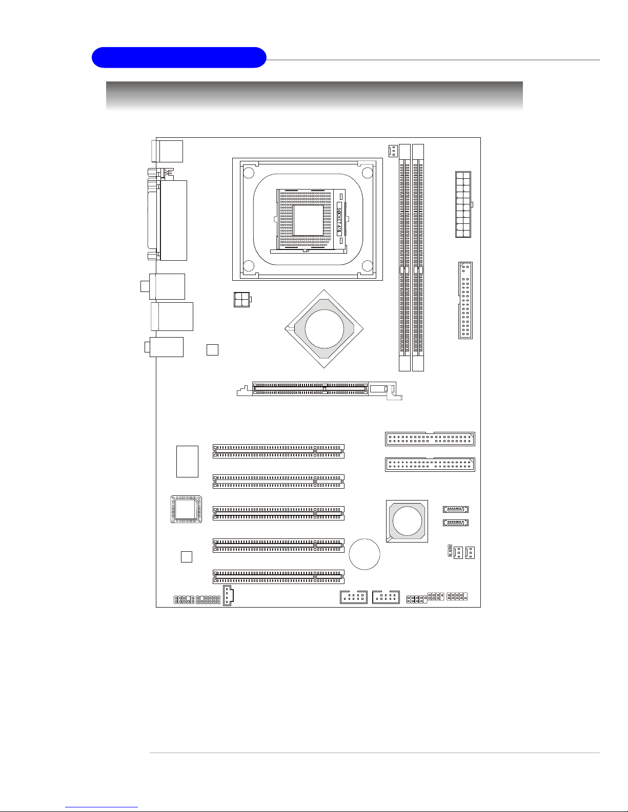
Mainboard Layout
PT8 Neo Series (MS-6799 v1.X) ATX Mainboard
BATT
+
D
D
R
1
D
D
R
2
JSP1
JAUD1
JUSB1 JUSB2
ATX
Power Suppl
y
SFAN2
SFAN1
CFAN1
SATA2
SATA1
JFP1
JFP2
Codec
Winbond
W83697HF
Realtek
8201BL
BIOS
PCI Slot 5
PCI Slot 4
PCI Slot 3
PCI Slot 2
PCI Slot 1
IDE 2
IDE 1
FDD1
JPW1
Top : Pa ra l l e l P ort
Bottom:
COMA
Top : mouse
Bottom: keyboard
T: LA N jack
B: USB ports
T: SPDIF Out
B: USB ports
JCD1
AGP Slot
T:
M:
B:
Line-In
Line-Out
Mic
JBAT1
JDB1
VIA
VT8237
VIA
PT800
Page 11
1-5
Getting Started
MSI Special Features
Color Management
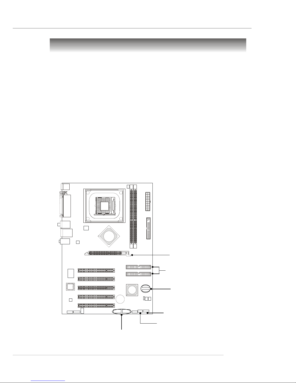
MSI has a unified color management rule for some connectors on the
mainboards, which helps you to install the memory modules, expansion cards
and other peripherals devices more easily and conveniently.
h Intel spec IDE ATA133 connector: yellow
h Serial ATA150 connector: orange
h AGP 8X slot: red
h USB 2.0 connector: yellow
h Front panel connector JFP1: HDD LED in red, Reset Switch in blue,
Power Switch in black, Power LED in light green.
h Front panel connector JFP2: Power LED in light green.
Front Panel Connector JFP2
USB 2.0 Connectors
AGP Slot
Intel Spec IDE ATA133 Connectors
Front Panel Connector JFP1
Serial ATA150 Connectors
(Optional)
Page 12
1-6
MS-6799 ATX Mainboard
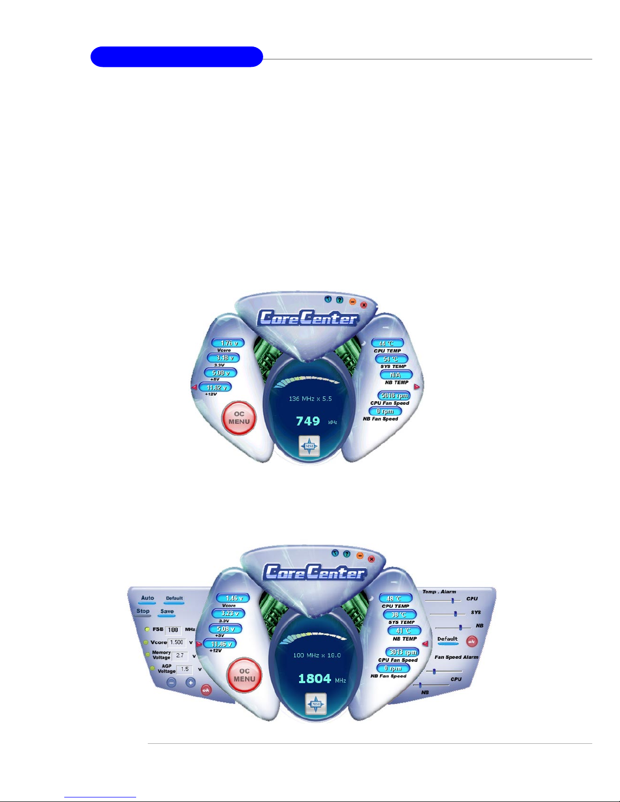
CoreCenter
CoreCenter
(TM)
- contains OC Menu panel, users can determine their
processor and memory type to optimize its memory capacity. This all-in-one
hardware console is advanced combination of the popular PC Alert and Fuzzy
Logic. Including powerful function with hardware monitor, system alert and
instinctive UI of overclocking, CoreCenter is just like your PC doctor that can
detect, view and adjust the PC hardware and system status during real time
operation.
In the left side it shows the current system status including the Vcore, 3.
3V, +5V and 12V. In the right side it shows the current PC hardware status such
as the CPU & system temperatures and all fans speeds.
When you click the red triangles in the left and right sides, two submenus will open for users to overclock, overspec or to adjust the thresholds of
system to send out the warning messages. If you click the Core Center button
in the top, a screen pops up for you to choose the “Auto mode” or “User
mode” of CPU fan.
Page 13
1-7
Getting Started
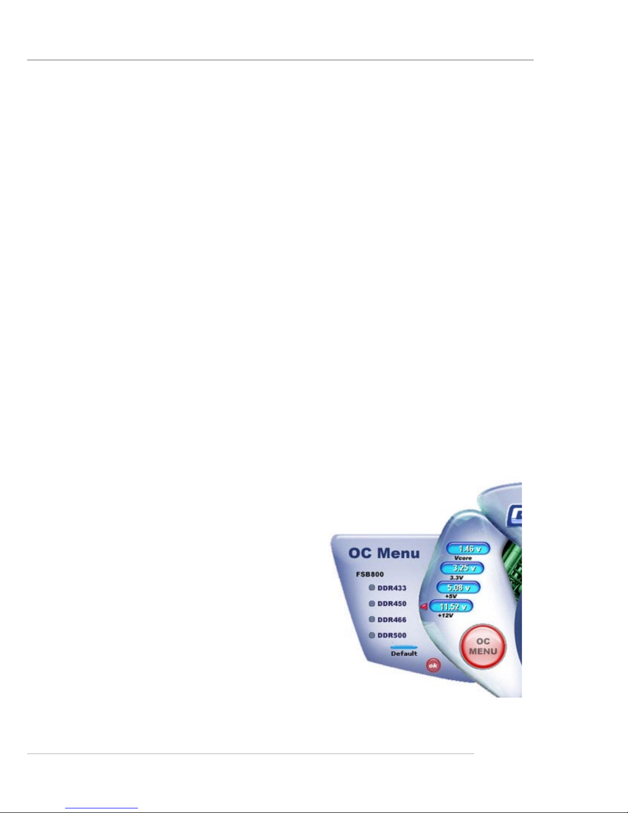
Left-wing: Current system status
In the left sub-menu, you can configure the settings of FSB, Vcore,
Memory Voltage and AGP Voltage by clicking the radio button in front of each
item and make it available (the radio button will be lighted as yellow when
selected), use the “+” and “-” buttons to adjust, then click
““
““
“OK
””
””
” to apply the
changes. Then you can click Save to save the desired FSB you just configured.
Also you may click Auto to start testing the maximal CPU overclocking
value, The CPU FSB will automatically increase the testing value until the PC
reboots. Or you may click Default to restore the default values.
Right-wing: PC hardware status during real time operation
In the right sub-menu, here you can configure the PC hardware status
such as CPU & system temperatures and fan speeds. You may use the scroll
bars to adjust each item, then click
““
““
“OK
””
””
” to apply the changes. The values you
set for the temperatures are the maximum thresholds for the system for warnings,
and the value for fan speeds are the minimum thresholds.
T op-side: User mode/Auto mode
Here you may adjust the CPU fan speed. If you choose User mode, you
may adjust the CPU fan speed in 8 different modes, from Stop to Full speed.
OC Menu
The exclusive OC Menu is fully developed to support DDR400+ memory
modules. By comprehensive validation of
over 67 DDR400+ memory modules, MSI
concluded best parameters for DRAM
voltage, V io and other BIOS settings. Y ou
can select DDR433, DDR450, DDR466 and
DDR500 from DRAM frequency in BIOS
setting. Or you can just click on OC Menu
button to configure in the OC Menu at
CoreCenter. OC Menu will adjust the necessary parameters of voltage and frequency simultaneously. The only limitation was the margin of processor from
overclocking.
Page 14
1-8
MS-6799 ATX Mainboard
Live BIOS™/Live Driver™
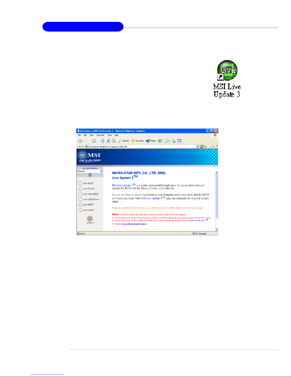
The Live BIOS™/Live Driver™ is a tool used to detect
and update your BIOS/drivers online so that you don’t need to
search for the correct BIOS/driver version throughout the whole
Web site. To use the function, you need to install the “MSI
Live Update 3” application. After the installation, the “MSI
Live Update 3” icon (as shown on the right) will appear on the
screen.
Double click the “MSI Live Update 3” icon, and the following screen will
appear:
Six buttons are placed on the left column of the screen. Click the desired
button to start the update process.
Ø Live BIOS – Updates the BIOS online.
Ø Live Driver – Updates the drivers online.
Ø Live VGA BIOS – Updates the VGA BIOS online.
Ø Live VGA Driver – Updates the VGA driver online.
Ø Live OSD – Updates the firmware of the OSD products online.
Ø Live Utility – Updates the utilities online.
If the product you purchased does not support any of the functions listed
above, a “sorry” message is displayed. For more information on the update
instructions, insert the companion CD and refer to the “Live Update Guide”
under the “Manual” Tab.
Page 15
1-9
Getting Started
Live Monitor™
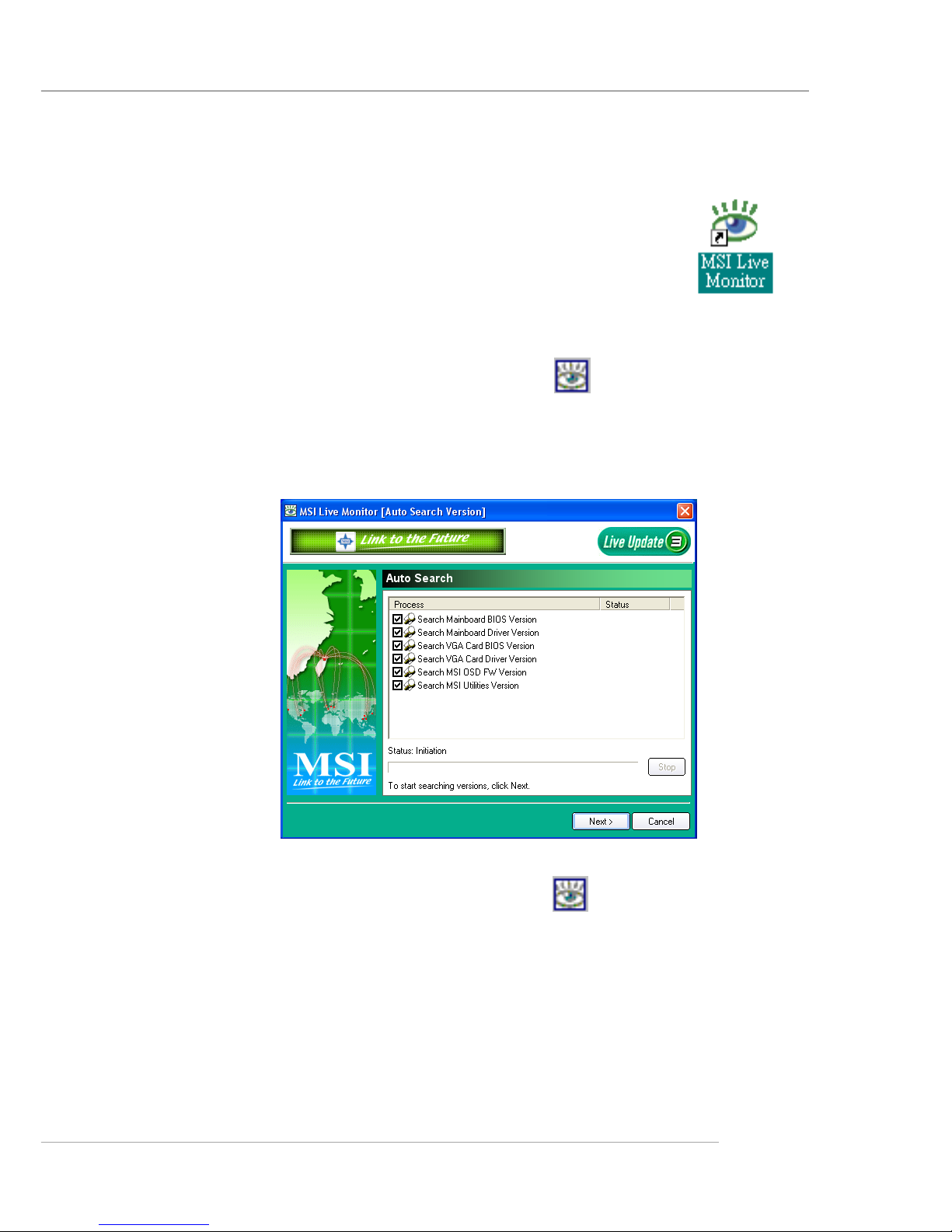
The Live Monitor™ is a tool used to schedule the search
for the latest BIOS/drivers version on the MSI Web site. To use
the function, you need to install the “MSI Live Update 3”
application. After installation, the “MSI Live Monitor” icon (as
shown on the right) will appear on the screen. Double click this
icon to run the application.
Double click the “MSI Live Monitor” icon at the lower-right corner
of the taskbar, and the following dialog box will appear. Y ou can specify how
often the system will automatically search for the BIOS/drivers version, or
change the LAN settings right from the dialog box.
You can right-click the MSI Live Monitor icon to perform the functions
listed below:
zz
zz
z Auto Search – Searches for the BIOS/drivers version you need immediately.
zz
zz
z View Last Result – Allows you to view the last search result if there is any.
zz
zz
z Preference – Configures the Search function, including the Search schedule.
zz
zz
z Exit – Exits the Live Monitor™ application.
zz
zz
z FAQ – Provides a link to a database which contains various possible questions
about MSI's products for users to inquire.
Page 16
1-10
MS-6799 ATX Mainboard
D-Bracket™ 2
1 2
3 4
D-Bracket™ 2 (Optional)
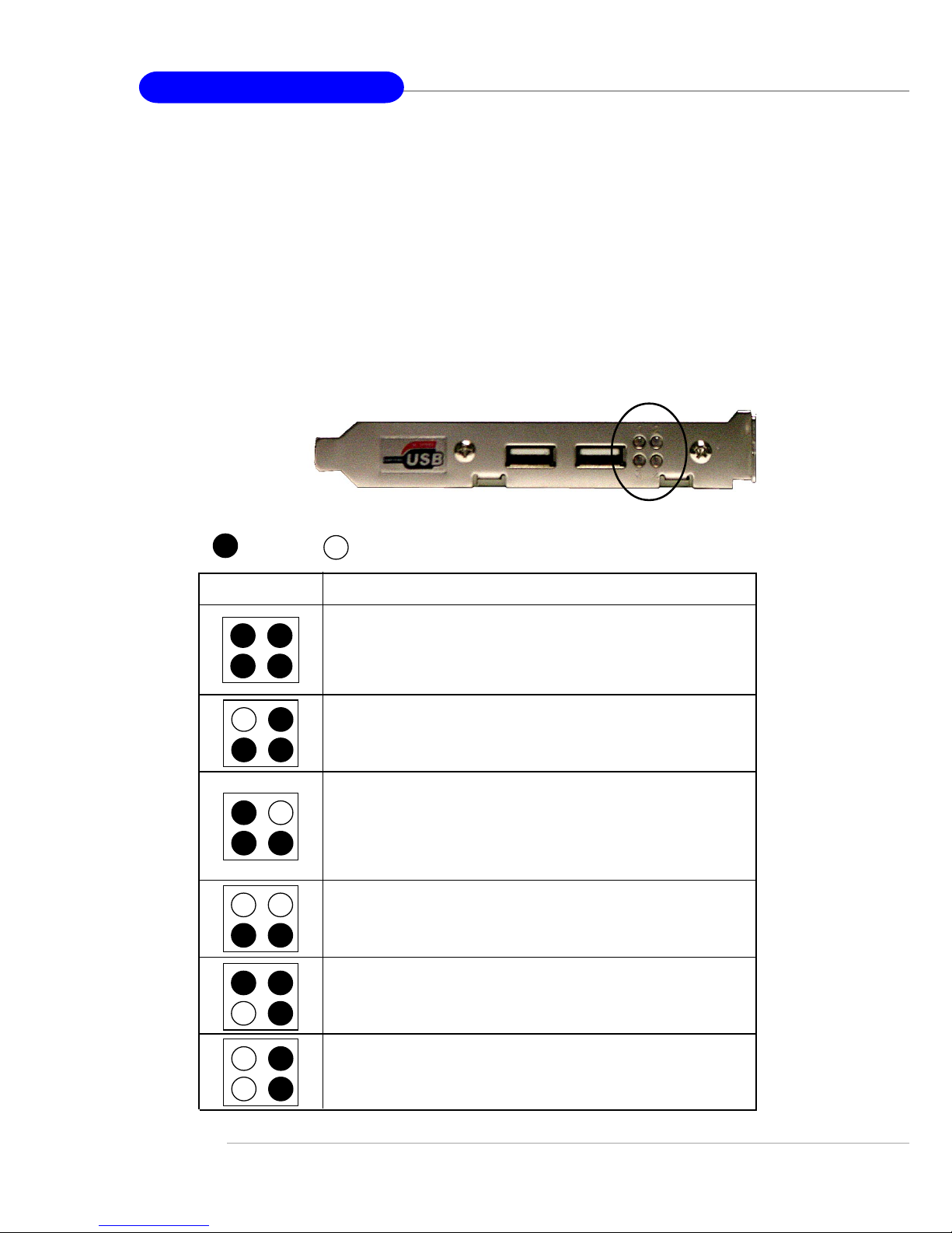
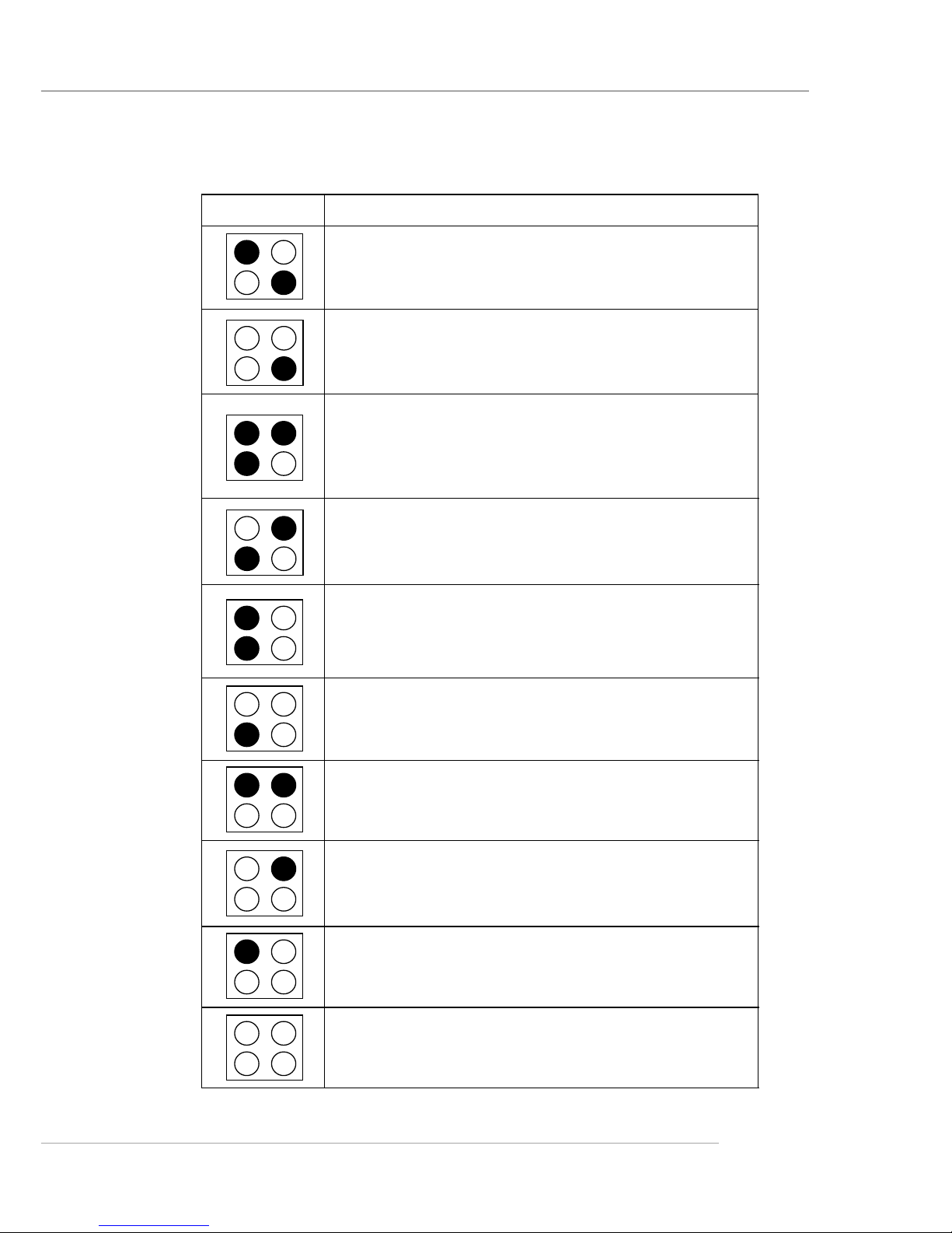
D-Bracket™ 2 is an external USB bracket integrating four Diagnostic
LEDs, which use graphic signal display to help users understand their system.
The LEDs provide up to 16 combinations of signals to debug the system. The
4 LEDs can debug all problems that fail the system, such as VGA, RAM or
other failures. This special feature is very useful for the overclocking users.
These users can use the feature to detect if there are any problems or failures.
D-Bracket™ 2 supports both USB 1.1 & 2.0 spec.
Red
Green
Description
System Power ON
- The D-LED will hang here if the processor is damaged or not installed properly.
Early Chipset Initialization
Memory Detection Test
- Testing onboard memory size. The D-LED will hang
if the memory module is damaged or not installed
properly.
Decompressing BIOS image to RAM for fast booting.
1 2
3 4
Initializing Keyboard Controller.
Testing VGA BIOS
- This will start writing VGA sign-on message to the
screen.
D-Bracket™ 2
Page 17
1-11
Getting Started
D-Bracket™ 2
Description
Processor Initialization
- This will show information regarding the processor
(like brand name, system bus, etc...)
Testing RTC (Real Time Clock)
Initializing Video Interface
- This will start detecting CPU clock, checking type of
video onboard. Then, detect and initialize the video
adapter.
BIOS Sign On
- This will start showing information about logo, processor brand name, etc...
Testing Base and Extended Memory
- Teting base memory from 240K to 640K and extended memory above 1MB using various patterns.
Assign Resources to all ISA.
Initializing Hard Drive Controller
- This will initialize IDE drive and controller.
Initializing Floppy Drive Controller
- This will initialize Floppy Drive and controller.
Boot Attempt
- Thi will set low stack and boot via INT 19h.
Operating System Booting
1 2
3 4
Page 18
1-12
MS-6799 ATX Mainboard
Round Cable (Optional)
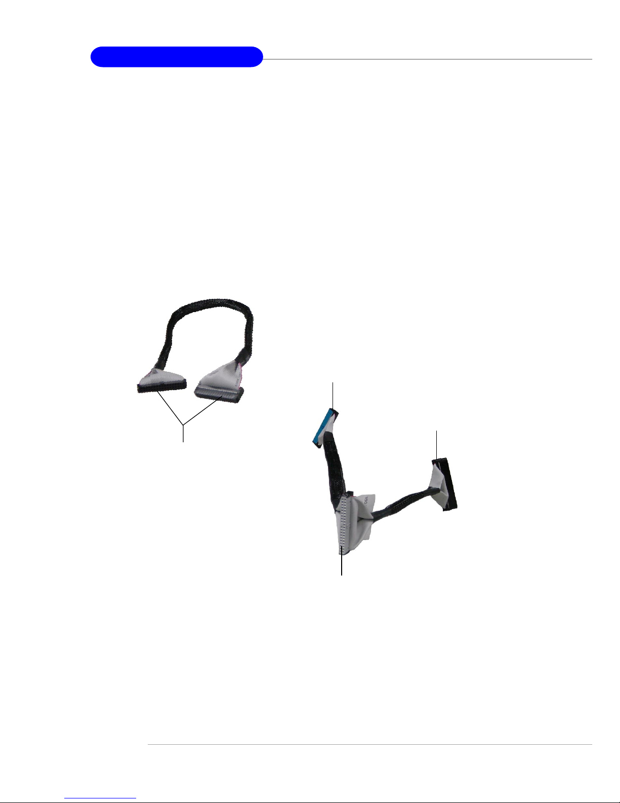
Round cable is an enhanced cable for PCI IDE and Ultra DMA controller.
It has the following benefits:
h Data transfer rate started by 133MB/s
h Backward compatibility (AT A33/66/100/133)
h Higher performance than traditional Flat cable (data rate)
h Improved data robustness
h Better airflow due to thinner ATA/133 cable
Connect to the system
connectors on the mainboard.
Connect to the slave drive.
Connect to the master drive.
Connect one end to the
floopy disk drive
connector (FDD1) and
the other end to the
standard flooy disk.
Page 19
1-13
Getting Started
CPU Thermal Protection
Aimed to prevent the CPU from overheating, MSI has developed a CPU
Thermal Protection mechanism for Intel® CPU platform. This CPU Thermal
Protection mechanism works on a thermal signal sensor. If the mechanism
senses an abnormal temperature rise, it will automatically shut down the system
and the CPU temperature will then drop down and resume normal. With this
unique feature, users can better protect their CPU. Please note that this feature
is for Intel® Pentium CPU only.
S-Bracket (Optional)
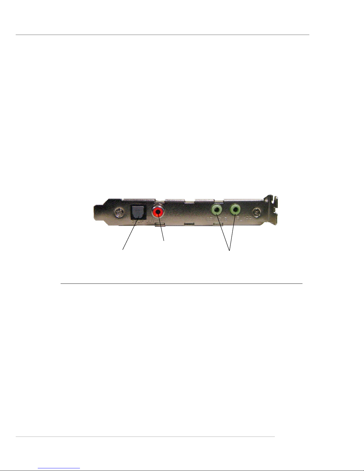
S-Bracket is a bracket which provides 2 SPDIF jacks for digital audio
transmission and 2 analog Line-Out connectors for additional 4-channel analog
audio output. With the S-Bracket, your system will be able to perform 6channel audio operation for wonderful surround sound effect, or connect to
Sony & Philips Digital Interface (SPDIF) speakers for audio transmission with
better quality.
The S-Bracket offers two types of SPDIF connectors: one for optical
fiber and the other for coaxial connection. Select the appropriate one to meet
your need. For more information on S-Bracket, refer to Appendix. Using 4- or
6-Channel Audio Function.
S-Bracket
SPDIF jack (optical)
SPDIF jack (coaxial)
Analog Line-Out jacks
Page 20

2-1
Hardware Setup
Chapter 2. Hardware
Setup
This chapter tells you how to install the CPU, memory
modules, and expansion cards, as well as how to setup the
jumpers on the mainboard. Also, it provides the instructions on
connecting the peripheral devices, such as the mouse, keyboard,
etc.
While doing the installation, be careful in holding the
components and follow the installation procedures.
Hardware Setup
Page 21
2-2
MS-6799 ATX Mainboard
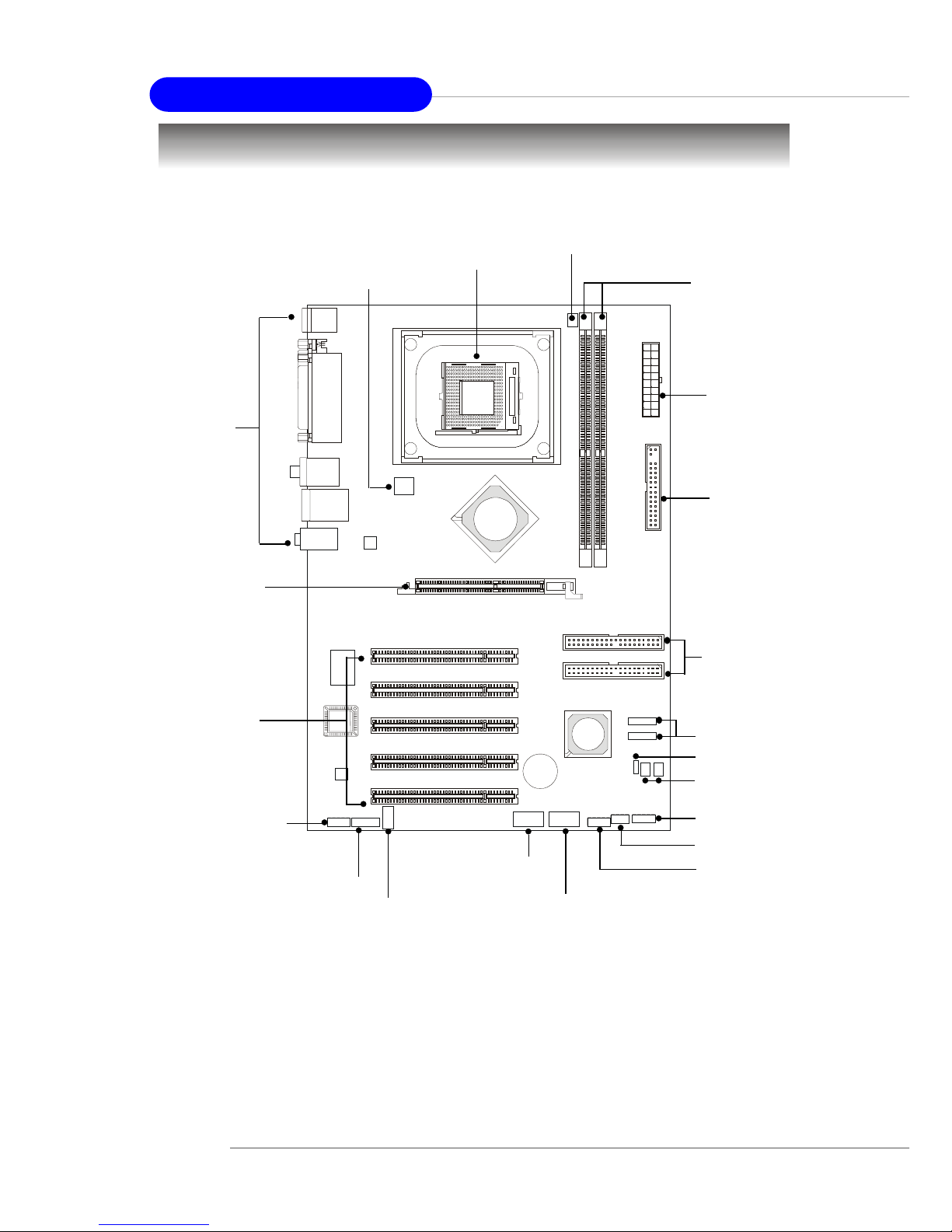
Quick Components Guide
DDR DIMMs, p.2-4
CPU, p.2-3
Back Panel
I/O, p.2-6
JUSB1, p.2-10
JSP1, p.2-13
JFP1, p.2-10
AGP Slot, p.2-15
PCI Slots, p.2-15
IDE1, IDE2, p.2-8
CFAN1, p.2-7
SFAN2/SFAN1,
p.2-7
JFP2, p.2-10
JAUD1, p.2-11
JDB1, p.2-12
JUSB2, p.2-10
SATA1, SATA2, p.2-9
ATX1, p.2-6
FDD1, p.2-7
JBAT1, p.2-14
JCD1, p.2-9
JPW1, p.2-6
Page 22
2-3
Hardware Setup
Central Processing Unit: CPU
CPU Core Speed Derivation Procedure
If CPU Clock = 200MHz
Core/Bus ratio = 12
then CPU core speed = Host Clock x Core/Bus ratio
= 200MHz x 12
= 2.4 GHz
The mainboard supports Intel® Pentium® 4 processors in the 478 pin
package. The mainboard uses a CPU socket called PGA478 for easy CPU
installation. When you are installing the CPU, make sure the CPU has a heat
sink and a cooling fan attached on the top to prevent overheating. If you do not
have the heat sink and cooling fan, contact your dealer to purchase and install
them before turning on the computer.
MSI Reminds Y ou...
Overheating
Overheating will seriously damage the CPU and system, always
make sure the cooling fan can work properly to protect the CPU
from overheating.
Overclocking
This motherboard is designed to support overclocking. However,
please make sure your components are able to tolerate such
abnormal setting, while doing overclocking. Any attempt to
operate beyond product specifications is not recommended. We
do not guarantee the damages or risks caused by inadequate
operation or beyond product specifications.
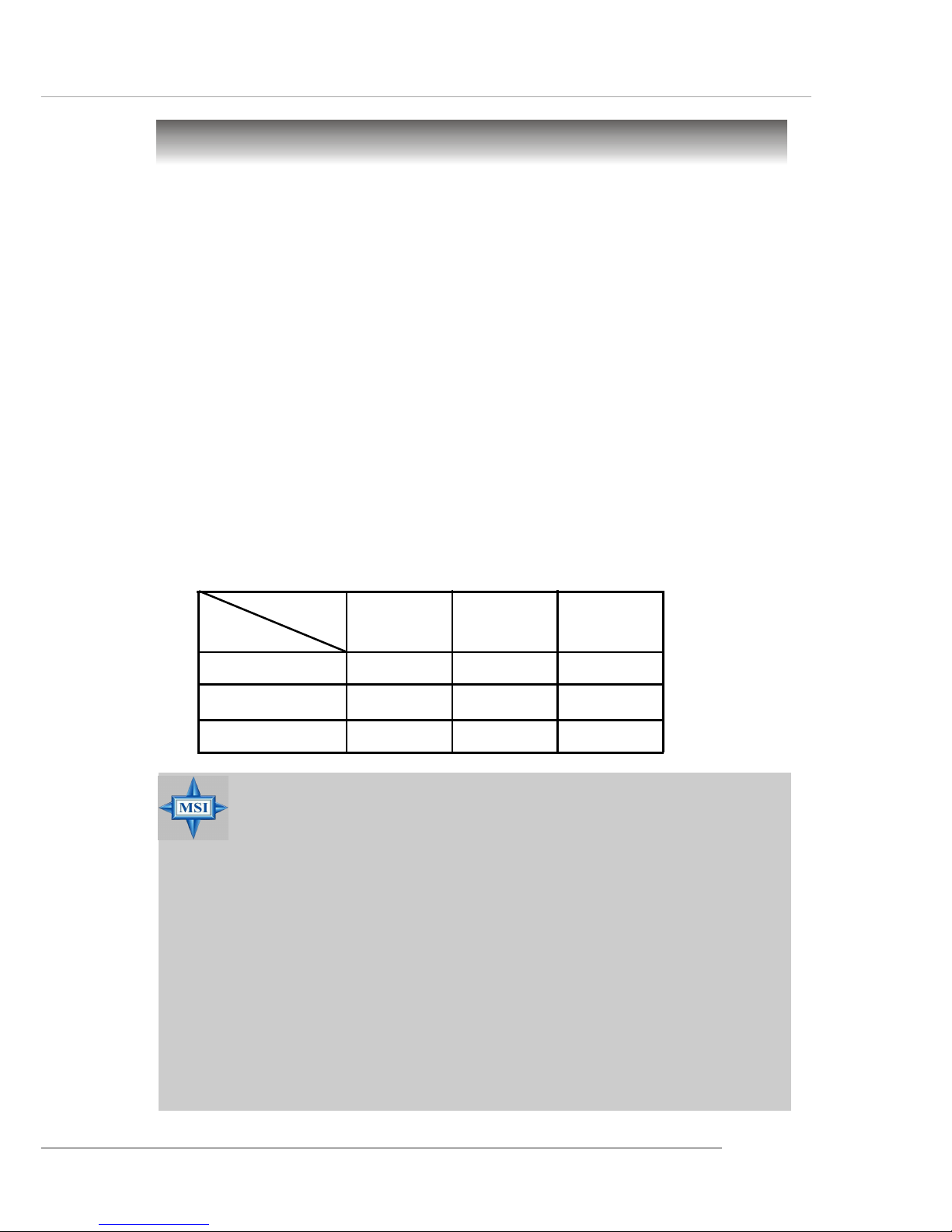
Memory Speed/CPU FSB Support Matrix
FSB
Memory
DDR 266
400 MHz
DDR 333 DDR 400
533 MHz
800 MHz
N/A
OKOK
OKOK
OK
OKOK
OKOK
OK
OK
N/A
OKOK
OKOK
OK
OKOK
OKOK
OK
OKOK
OKOK
OK
OKOK
OKOK
OK
Page 23
2-4
MS-6799 ATX Mainboard
Memory
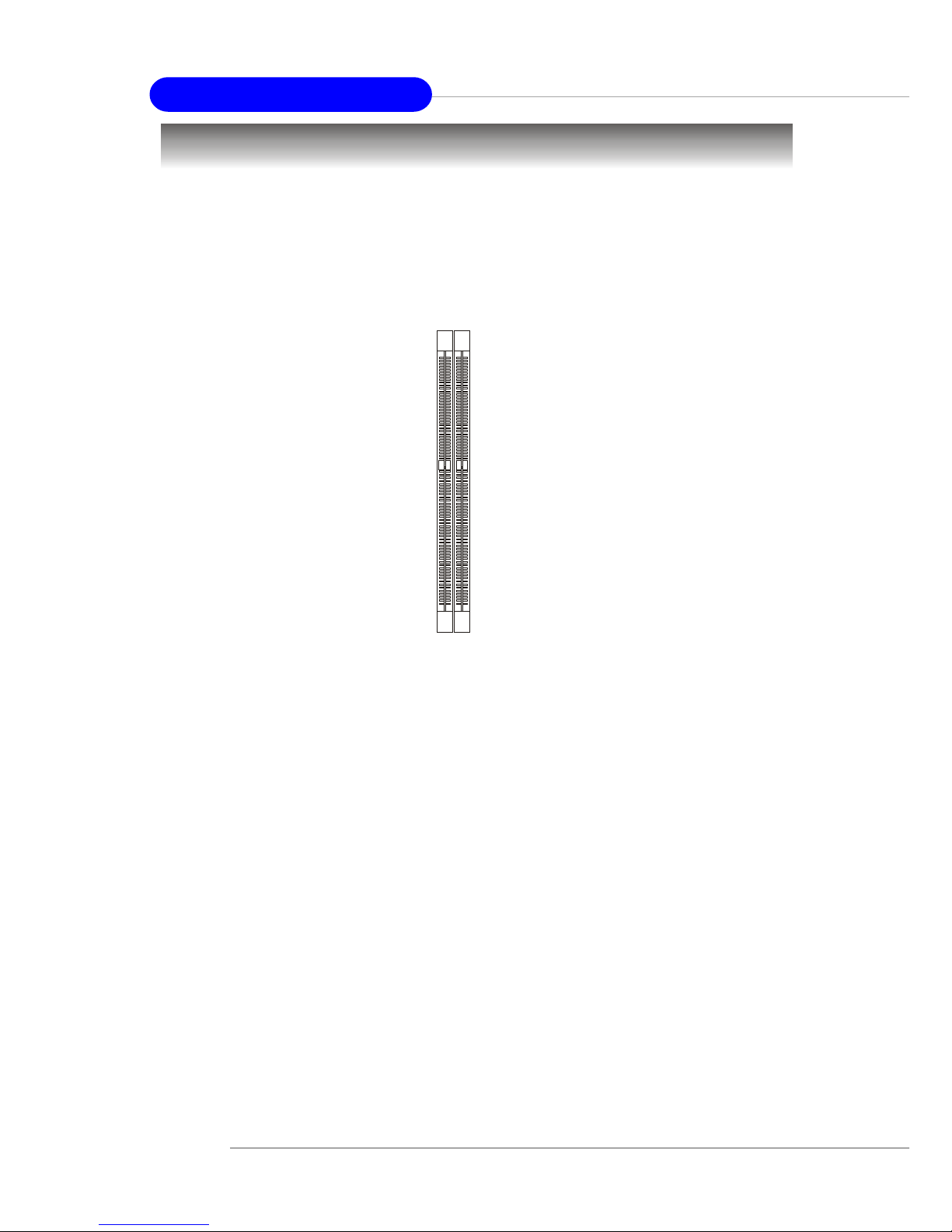
DIMM1-2
The mainboard provides 2 slots for 184-pin, 2.5V DDR DIMM modules
and supports the memory size up to 2 GB without ECC,. Y ou can install DDR266/
DDR333/DDR400 DDR SDRAM modules on the DDR DIMM slots. T o operate
properly, at least one DIMM module must be installed.
Introduction to DDR SDRAM
DDR (Double Data Rate) SDRAM is similar to conventional SDRAM,
but doubles the rate by transferring data twice per cycle. It uses 2.5 volts as
opposed to 3.3 volts used in SDR SDRAM, and requires 184-pin DIMM modules rather than 168-pin DIMM modules used by SDR SDRAM. Three types of
DDR are available at the time of writing: DDR266, DDR333 & DDR400. DDR266
DDR SDRAM running at 133MHz will produce about 1.6GB/s memory
bandwidth. DDR333 running at 166MHz will produce 2.1GB/s memory
bandwidth. DDR400 is also available with bandwidith up to 3.2GB/s for singlechannel mode or with 6.4GB/s for dual-channel mode. High memory bandwidth makes DDR an ideal solution for high performance PC, workstations and
servers.
DDR DIMM Module Combination
Install at least one DIMM module on the slots. Memory modules can be
installed on the slots in any order . You can install either single- or double-side
modules to meet your own needs.
Page 24
2-5
Hardware Setup
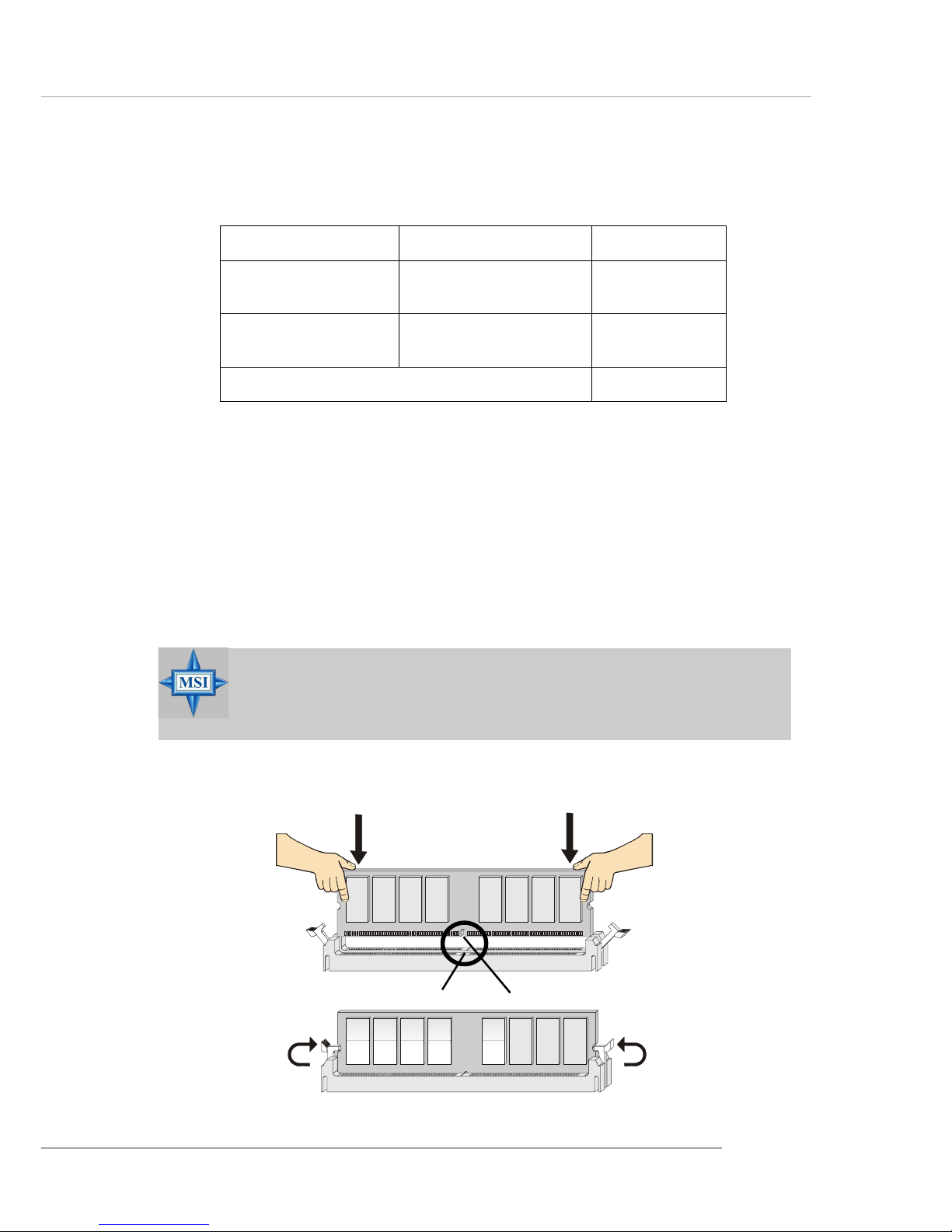
Installing DDR Modules
1. The DDR DIMM has only one notch on the center of module. The module
will only fit in the right orientation.
2. Insert the DIMM memory module vertically into the DIMM slot. Then
push it in until the golden finger on the memory module is deeply inserted
in the socket.
3. The plastic clip at each side of the DIMM slot will automatically close.
MSI Reminds Y ou...
You can barely see the golden finger if the module is properly
inserted in the socket.
Volt
Notch
Memory modules can be installed in any combination as follows:
S: Single Side D: Double Side
Slot Memory Module Total Memory
DIMM 1
(Bank 0 & 1)
S/D 64MB~1GB
DIMM 2
(Bank 2 & 3)
S/D 64MB~1GB
Maximum System Memory Supported
64MB~2GB
Page 25
2-6
MS-6799 ATX Mainboard
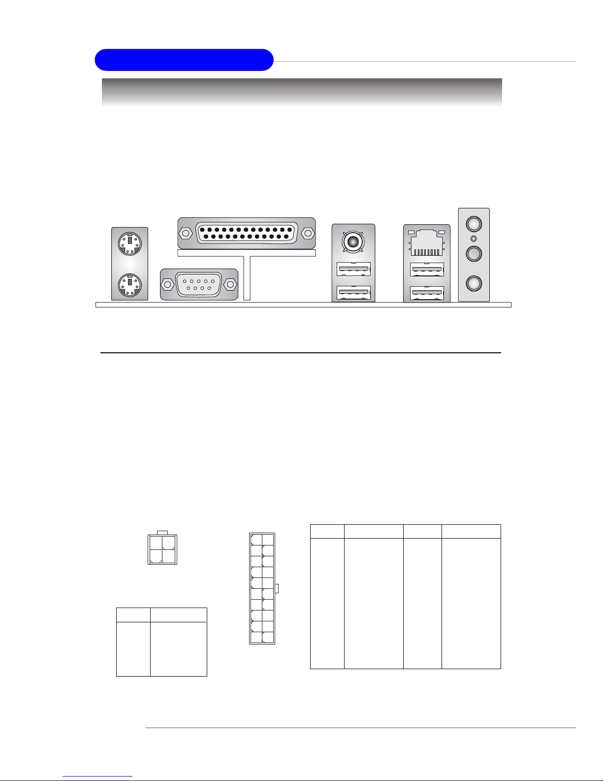
The back panel provides the following connectors:
Back Panel / Power Supply
Mouse
Parallel
COM A
USB Ports
Keyboard
L-out
L-in
MIC
LAN
(Optional)
USB Ports
SPDIF-Out
A TX 20-Pin Power Connector: A TX1
This connector allows you to connect to an ATX power supply. To
connect to the ATX power supply, make sure the plug of the power supply is
inserted in the proper orientation and the pins are aligned. Then push down
the power supply firmly into the connector.
A TX 12V Power Connector: JPW1
This 12V power connector is used to provide power to the CPU.
PIN SIGNAL
1 GND
2 GND
3 12V
4 12V
JPW1 Pin Definition
PIN SIGNAL
11 3.3V
12 -12V
13 GND
14 PS_ON
15 GND
16 GND
17 GND
18 -5V
19 5V
20 5V
PIN SIGNAL
1 3.3V
2 3.3V
3 GND
45V
5 GND
65V
7 GND
8 PW_OK
9 5V_SB
10 12V
ATX1 Pin Definition
JPW1
1
3
4
2
ATX1
10
1
20
11
Page 26
2-7
Hardware Setup
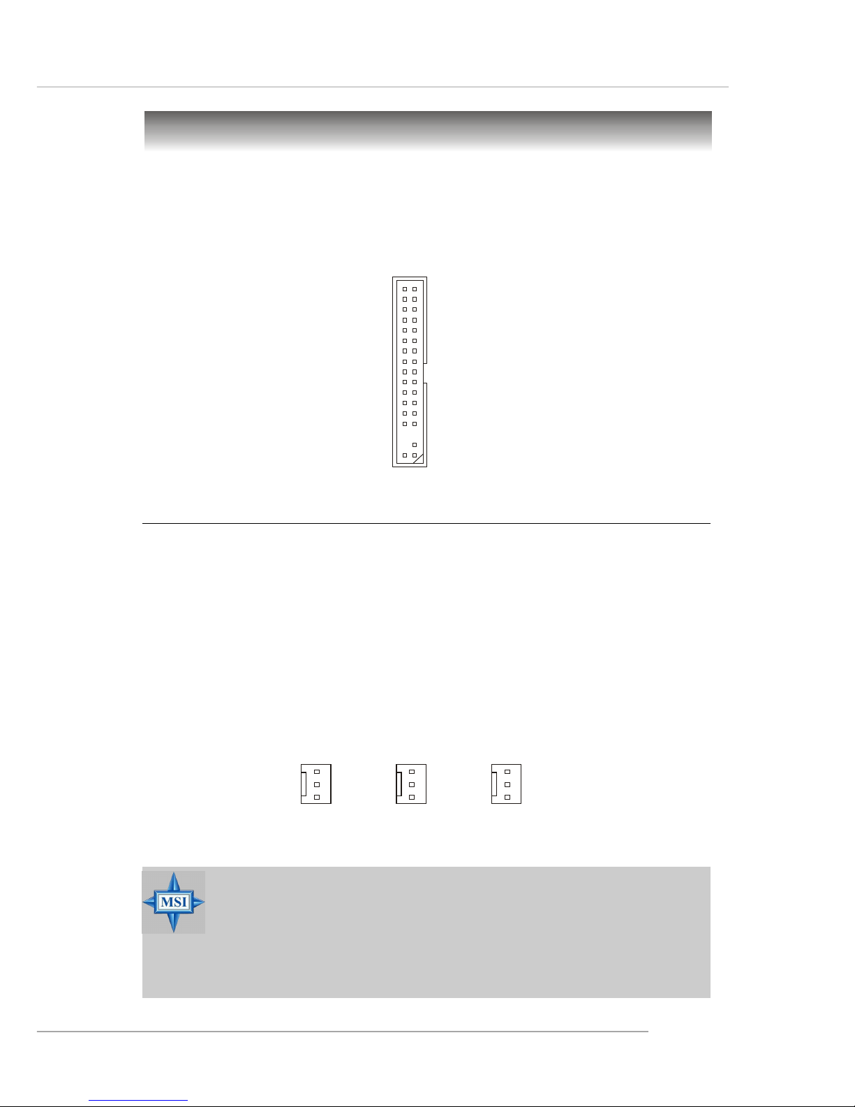
Floppy Disk Drive Connector: FDD1
The mainboard provides a standard floppy disk drive connector that
supports 360K, 720K, 1.2M, 1.44M and 2.88M floppy disk types.
Connectors
FDD1
Fan Power Connectors: CF AN1/SF AN1/SF AN2
The CPUF AN1 (processor fan), SF AN1, and SFAN2 (system fan) support
system cooling fan with +12V. When connecting the wire to the connectors,
always take note that the red wire is the positive and should be connected to
the +12V, the black wire is Ground and should be connected to GND. If the
mainboard has a System Hardware Monitor chipset on-board, you must use a
specially designed fan with speed sensor to take advantage of the CPU fan
control.
MSI Reminds Y ou...
1. Always consult the vendors for proper CPU cooling fan.
2. CFAN1 supports the fan contr ol. You can install the PC Alert
utility that will automatically control the CPU fan speed
according to the actual CPU temperature.
CF AN1
Sensor
+12V
GND
SF AN1
Sensor
+12V
GND
SF AN2
(Optional)
Sensor
+12V
GND
Page 27
2-8
MS-6799 ATX Mainboard
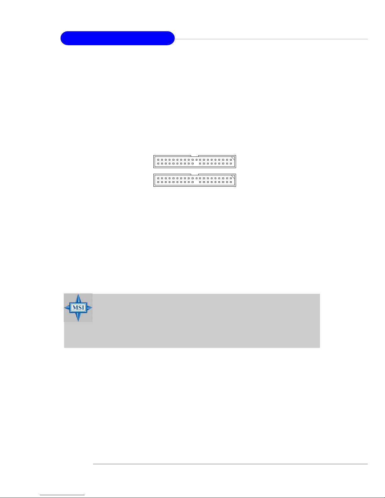
AT A133 Hard Disk Connectors: IDE1 & IDE2
The mainboard has a 32-bit Enhanced PCI IDE and Ultra DMA 33/66/100/
133 controller that provides PIO mode 0~5, Bus Master, and Ultra DMA 33/66/
100/133 function. Y ou can connect up to four hard disk drives, CD-ROM, 120MB
Floppy and other devices. These connectors support the provided IDE hard
disk cable.
IDE1 (Primary IDE Connector)
The first hard drive should always be connected to IDE1. IDE1 can connect a
Master and a Slave drive. You must configure second hard drive to Slave mode
by setting the jumper accordingly.
IDE2 (Secondary IDE Connector)
IDE2 can also connect a Master and a Slave drive.
MSI Reminds Y ou...
If you install two hard disks on cable, you must configure the
second drive to Slave mode by setting its jumper. Refer to the
hard disk documentation supplied by hard disk vendors for
jumper setting instructions.
IDE1
IDE2
Page 28
2-9
Hardware Setup
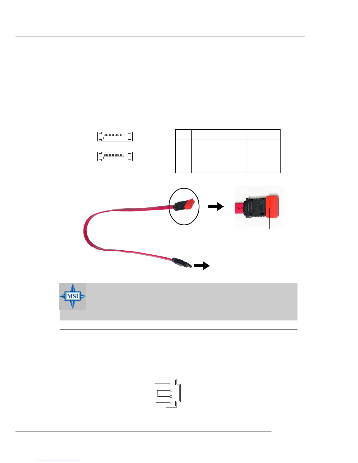
Serial A TA HDD Connectors: SA TA1, SA TA2 (Optional)
The mainboard provides dual high-speed Serial ATA interface ports.
The ports support 1st generation Serial ATA data rates of 150MB/s and are
fully compliant with Serial AT A 1.0 specifications. Each Serial ATA connector
can connect to 1 hard disk drive.
PIN SIGNAL PIN SIGNAL
1 GND 2 TXP
3 TXN 4 GND
5 RXN 6 RXP
7 GND
Pin Definition
Connect to SATA1 or SATA2
Take out the dust cover and
connect to the hard disk
devices
Optional Serial A TA cable
MSI Reminds Y ou...
Please do not fold the Serial ATA cable into 90-degree angle.
Otherwise, the loss of data may occur during transmission.
SATA2
SATA1
7 1
CD-In Connector: CD1
The connector is for CD-ROM audio connector.
CD1
GND
L
R
Page 29
2-10
MS-6799 ATX Mainboard
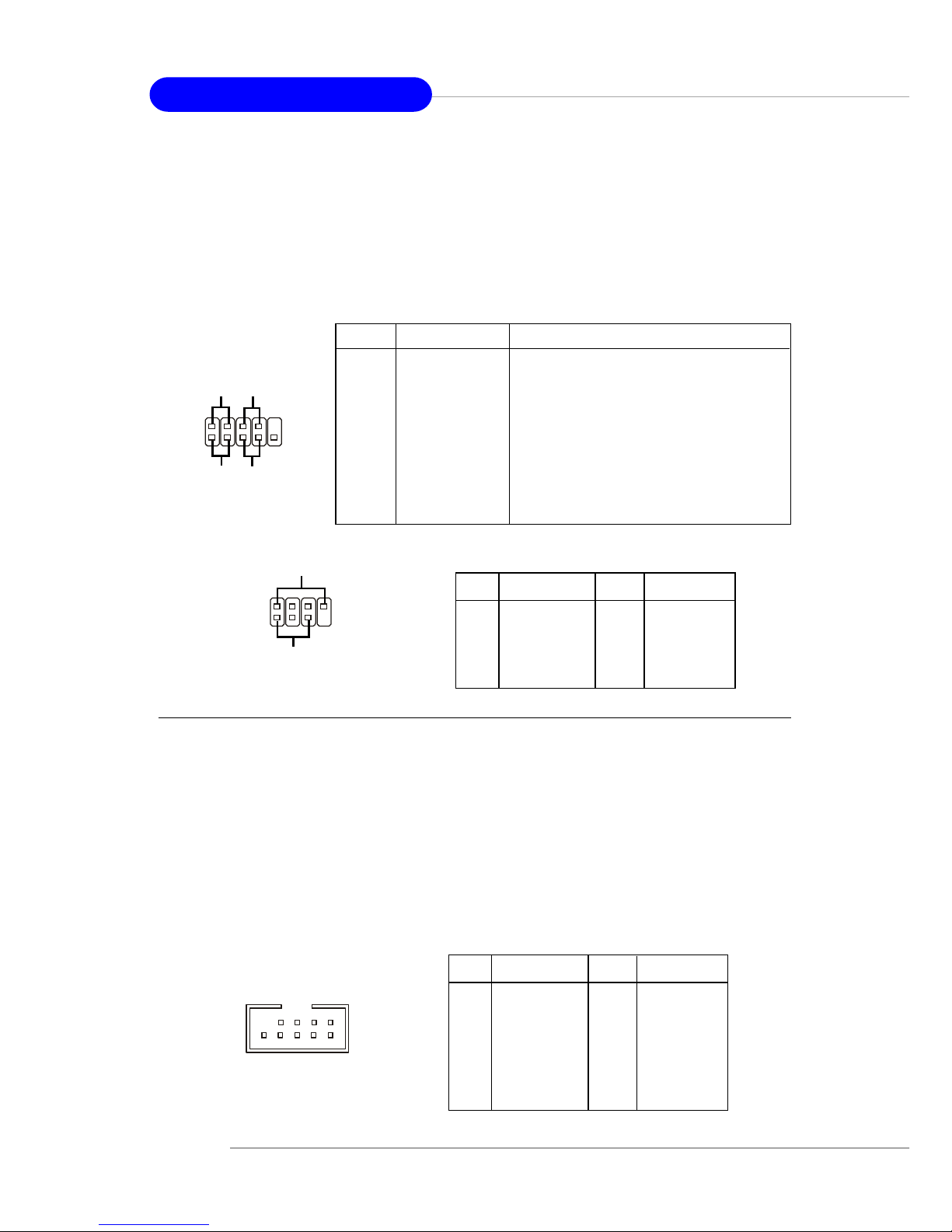
Front Panel Connectors: JFP1 & JFP2
The mainboard provides two front panel connectors for electrical
connection to the front panel switches and LEDs. JFP1 is compliant with Intel
®
Front Panel I/O Connectivity Design Guide.
Power
LED
Speaker
1
2
7
8
JFP2
PIN SIGNAL DESCRIPTION
1 HD_LED_P Hard disk LED pull-up
2 FP PWR/SLP MSG LED pull-up
3 HD_LED_N Hard disk active LED
4 FP PWR/SLP MSG LED pull-up
5 RST_SW_N Reset Switch low reference pull-down to GND
6 PWR_SW_P Power Switch high reference pull-up
7 RST_SW_P Reset Switch high reference pull-up
8 PWR_SW_N Power Switch low reference pull-down to GND
9 RSVD_DNU Reserved. Do not use.
JFP1 Pin Definition
PIN SIGNAL PIN SIGNAL
1 GND 2 SPK3 SLED 4 BUZ+
5 PLED 6 BUZ7 NC 8 SPK+
JFP2 Pin Definition
PIN SIGNAL PIN SIGNAL
1 VCC 2 VCC
3 USB0- 4 USB15 USB0+ 6 USB1+
7 GND 8 GND
9 Key (no pin) 10 USBOC
Pin Definition
1
2
9
JUSB1 / JUSB2
Front USB Connectors: JUSB1 & JUSB2
The mainboard provides two USB 2.0 pin headers JUSB1 & JUSB2 that
are compliant with Intel® I/O Connectivity Design Guide. USB 2.0 technology
increases data transfer rate up to a maximum throughput of 480Mbps, which is
40 times faster than USB 1.1, and is ideal for connecting high-speed USB
interface peripherals such as USB HDD, digital cameras, MP3 players,
printers, modems and the like.
9
1
2
10
JFP1
HDD
LED
Reset
Switch
Power
LED
Power
Switch
10
Page 30
2-11
Hardware Setup
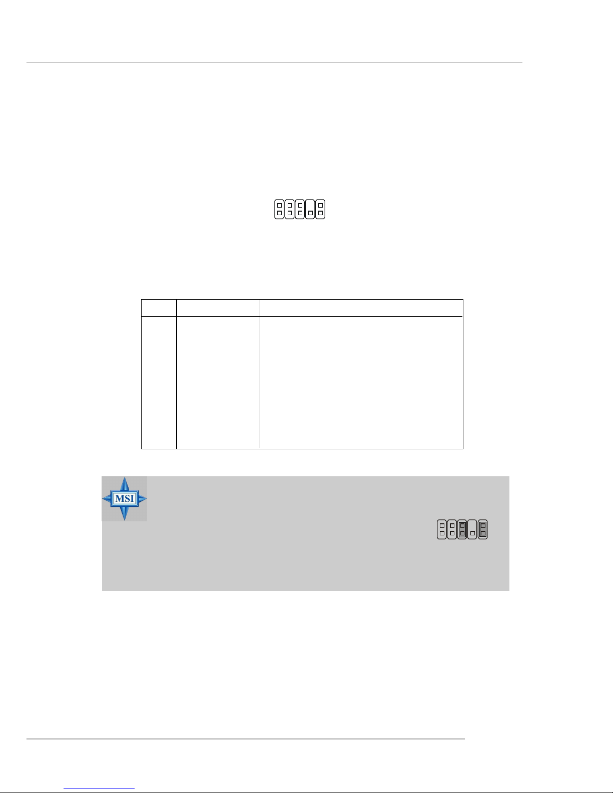
Front Panel Audio Connector: JAUD1
The JAUD1 front panel audio connector allows you to connect to the
front panel audio and is compliant with Intel® Front Panel I/O Connectivity
Design Guide.
JAUD1
1
2
9
10
PIN SIGNAL DESCRIPTION
1 AUD_MIC Front panel microphone input signal
2 AUD_GND Ground used by analog audio circuits
3 AUD_MIC_BIAS Microphone power
4 AUD_VCC Filtered +5V used by analog audio circuits
5 AUD_FPOUT_R Right channel audio signal to front panel
6 AUD_RET_R Right channel audio signal return from front panel
7 HP_ON Reserved for future use to control headphone amplifier
8 KEY No pin
9 AUD_FPOUT_L Left channel audio signal to front panel
10 AUD_RET_L Left channel audio signal return from front panel
JAUD1 Pin Definition
MSI Reminds Y ou...
If you don’t want to connect to the front audio
header, pins 5 & 6, 9 & 10 have to be jumpered in
order to have signal output directed to the rear
audio ports. Otherwise, the Line-Out connector on
the back panel will not function.
5
6
10
9
Page 31
2-12
MS-6799 ATX Mainboard
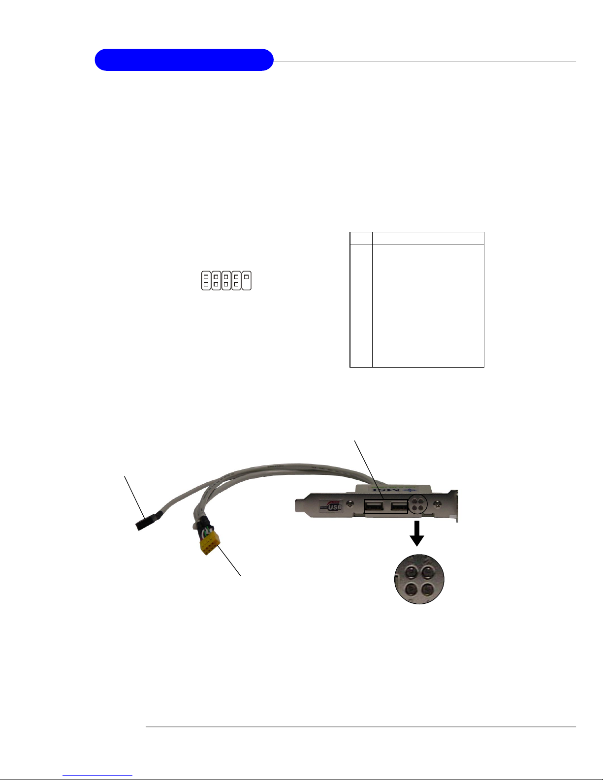
D-Bracket™ 2 Connector: JDB1
The mainboard comes with a JDB1 connector for you to connect to DBracket™ 2. D-Bracket™ 2 is a USB Bracket that supports both USB1.1 & 2.0
spec. It integrates four LEDs and allows users to identify system problem
through 16 various combinations of LED signals. For definitions of 16 signal
combinations, please refer to D-Bracket™ 2 in Chapter 1.
D-Bracket™ 2
Connected to JUSB2 (the USB
pinheader in yellow color)
Connected to JDB1
LEDs
Depending on the optional bracket you buy, please
note there might be a Bluetooth Sticker to cover one of
the port, which marks “Do no remove, when using
bluetooth”.
Pin Signal
1 DBG1 (high for green color)
2 DBR1 (high for red color)
3 DBG2 (high for green color)
4 DBR2 (high for red color)
5 DBG3 (high for green color)
6 DBR3 (high for red color)
7 DBG4 (high for green color)
8 DBR4 (high for red color)
9 Key
10 NC
JDB1 Pin Definition
JDB1
1
9
2
10
Page 32
2-13
Hardware Setup
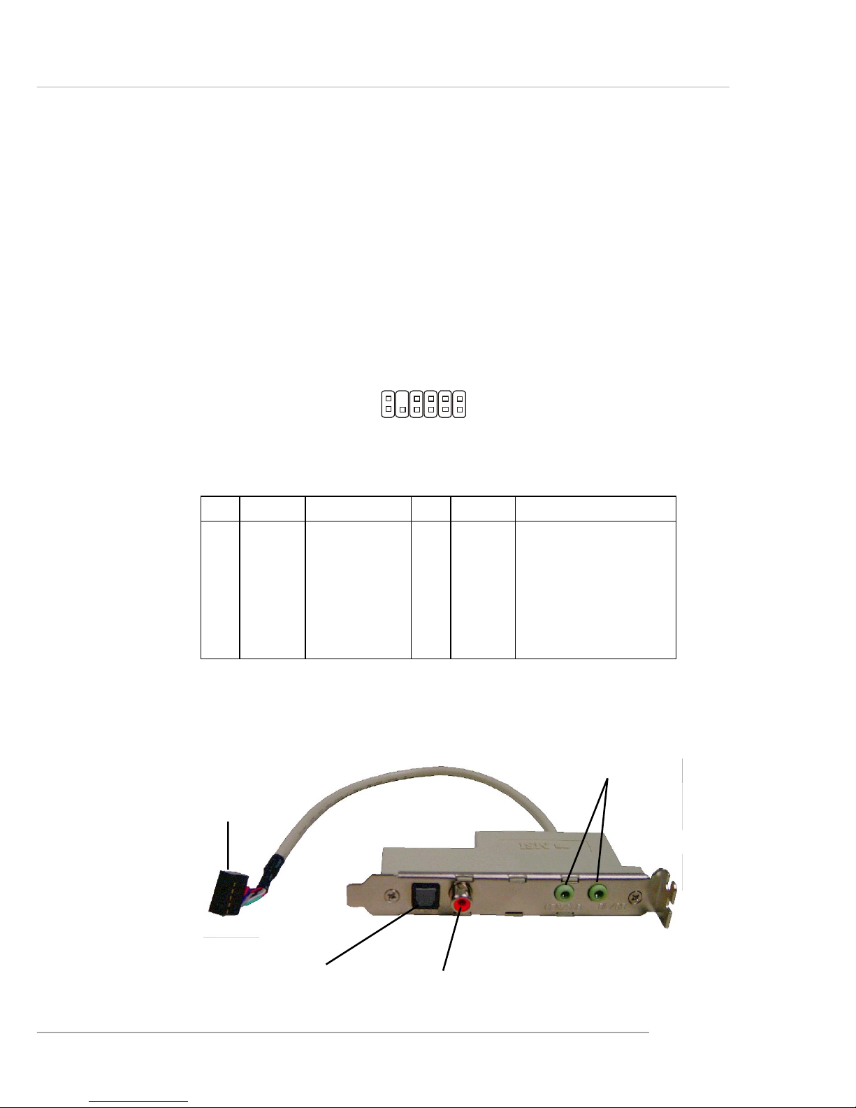
JSP1
1 11
12 2
PIN SIGNAL DESCRIPTION PIN SIGNAL DESCRIPTION
1 VCC5 VCC 5V 2 VDD3 VDD 3.3V
3 SPDFO S/PDIF output 4 (No Pin) K e y
5 GND Ground 6 SPDFI S/PDIF input
7 LFE-OUT Audio bass output 8 SOUT-R Audio right surrounding output
9 CET-OUT Audio center output 1 0 SOUT-L Audio left surrounding output
11 GND Ground 12 GND Ground
JSP1 Pin Definition
Optional S-Bracket
SPDIF jack (optical)
SPDIF jack (coaxial)
Analog Line-Out jack
Connect to JSP1
S-Bracket (SPDIF) Connector: JSP1 (Optional)
The connector allows you to connect a S-Bracket for Sony & Philips
Digital Interface (SPDIF). The S-Bracket offers 2 SPDIF jacks for digital audio
transmission (one for optical fiber connection and the other for coaxial), and 2
analog Line-Out jacks for 4-channel audio output.
T o attach the fiber-optic cable to optical SPDIF jack, you need to remove
the plug from the jack first. The two SPDIF jacks support SPDIF output only.
For more information on the S-Bracket, refer to Appendix: Using 4- or 6-Channel
Audio Function.
Page 33
2-14
MS-6799 ATX Mainboard
The motherboard provides the following jumpers for you to set the
computer’s function. This section will explain how to change your
motherboard’s function through the use of jumpers.
Clear CMOS Jumper: JBA T1
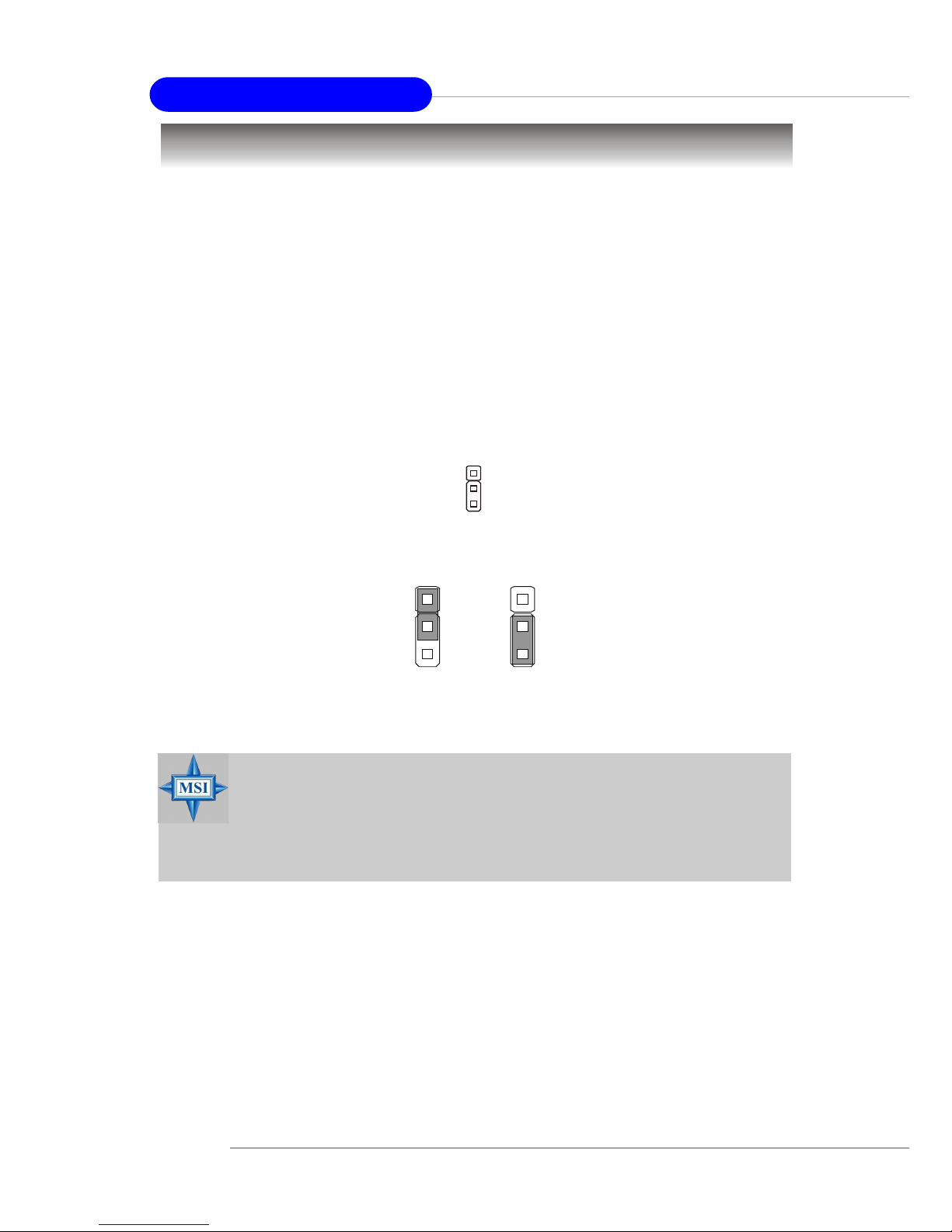
There is a CMOS RAM on board that has a power supply from external
battery to keep the data of system configuration. With the CMOS RAM, the
system can automatically boot OS every time it is turned on. If you want to
clear the system configuration, use the JBAT1 (Clear CMOS Jumper ) to clear
data. Follow the instructions below to clear the data:
Jumpers
MSI Reminds Y ou...
You can clear CMOS by shorting 2-3 pin while the system is off.
Then return to 1-2 pin position. Avoid clearing the CMOS while
the system is on; it will damage the mainboard.
JBAT1
1
Clear Data
1
3
Keep Data
1
3
Page 34
2-15
Hardware Setup
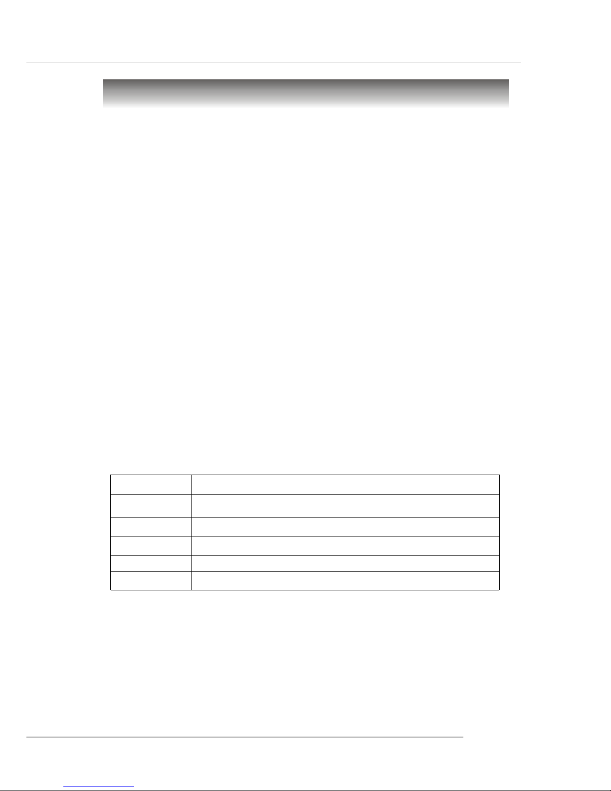
Order 1 Order 2 Order 3 Order 4
PCI Slot 1 INT A# INT B# INT C# INT D#
PCI Slot 2 INT B# INT C# INT D# INT A#
PCI Slot 3 INT C# INT D# INT A# INT B#
PCI Slot 4 INT D# INT A# INT B# INT C#
PCI Slot 5 INT A# INT B# INT C# INT D#
Slots
The motherboard provides one AGP slot and five 32-bit PCI bus slots.
AGP (Accelerated Graphics Port) Slot
The AGP slot allows you to insert the AGP graphics card. AGP is an
interface specification designed for the throughput demands of 3D graphics.
It introduces a 66MHz, 32-bit channel for the graphics controller to directly
access main memory. The slot supports 8x/4x AGP card.
PCI (Peripheral Component Interconnect) Slots
The PCI slots allow you to insert the expansion cards to meet your needs.
When adding or removing expansion cards, make sure that you unplug the
power supply first. Meanwhile, read the documentation for the expansion card
to make any necessary hardware or software settings for the expansion card,
such as jumpers, switches or BIOS configuration.
PCI Interrupt Request Routing
The IRQ, acronym of interrupt request line and pronounced I-R-Q, are
hardware lines over which devices can send interrupt signals to the
microprocessor. The PCI IRQ pins are typically connected to the PCI bus INT
A# ~ INT D# pins as follows:
Page 35

2-1
Hardware Setup
Chapter 2. Hardware
Setup
This chapter tells you how to install the CPU, memory
modules, and expansion cards, as well as how to setup the
jumpers on the mainboard. Also, it provides the instructions on
connecting the peripheral devices, such as the mouse, keyboard,
etc.
While doing the installation, be careful in holding the
components and follow the installation procedures.
Hardware Setup
Page 36
2-2
MS-6799 ATX Mainboard
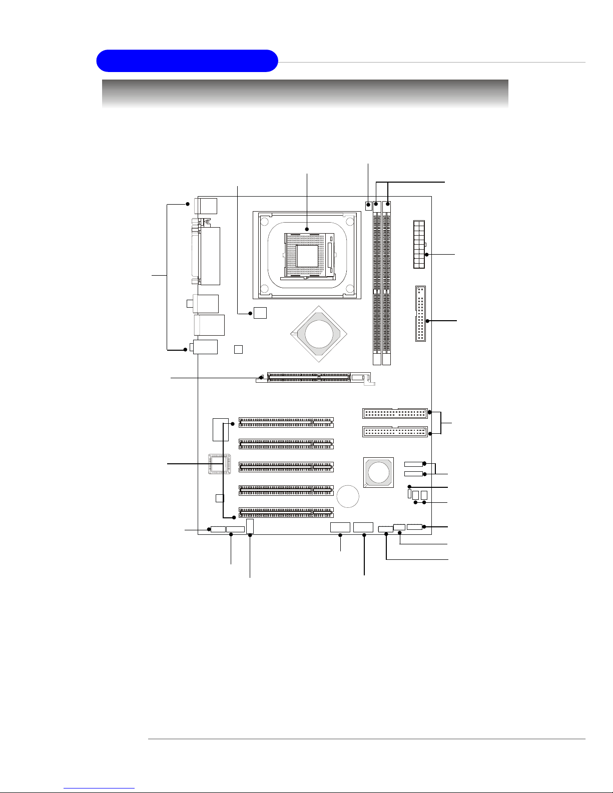
Quick Components Guide
DDR DIMMs, p.2-4
CPU, p.2-3
Back Panel
I/O, p.2-6
JUSB1, p.2-10
JSP1, p.2-13
JFP1, p.2-10
AGP Slot, p.2-15
PCI Slots, p.2-15
IDE1, IDE2, p.2-8
CFAN1, p.2-7
SFAN2/SFAN1,
p.2-7
JFP2, p.2-10
JAUD1, p.2-11
JDB1, p.2-12
JUSB2, p.2-10
SATA1, SATA2, p.2-9
ATX1, p.2-6
FDD1, p.2-7
JBAT1, p.2-14
JCD1, p.2-9
JPW1, p.2-6
Page 37
2-3
Hardware Setup
Central Processing Unit: CPU
CPU Core Speed Derivation Procedure
If CPU Clock = 200MHz
Core/Bus ratio = 12
then CPU core speed = Host Clock x Core/Bus ratio
= 200MHz x 12
= 2.4 GHz
The mainboard supports Intel® Pentium® 4 processors in the 478 pin
package. The mainboard uses a CPU socket called PGA478 for easy CPU
installation. When you are installing the CPU, make sure the CPU has a heat
sink and a cooling fan attached on the top to prevent overheating. If you do not
have the heat sink and cooling fan, contact your dealer to purchase and install
them before turning on the computer.
MSI Reminds Y ou...
Overheating
Overheating will seriously damage the CPU and system, always
make sure the cooling fan can work properly to protect the CPU
from overheating.
Overclocking
This motherboard is designed to support overclocking. However,
please make sure your components are able to tolerate such
abnormal setting, while doing overclocking. Any attempt to
operate beyond product specifications is not recommended. We
do not guarantee the damages or risks caused by inadequate
operation or beyond product specifications.
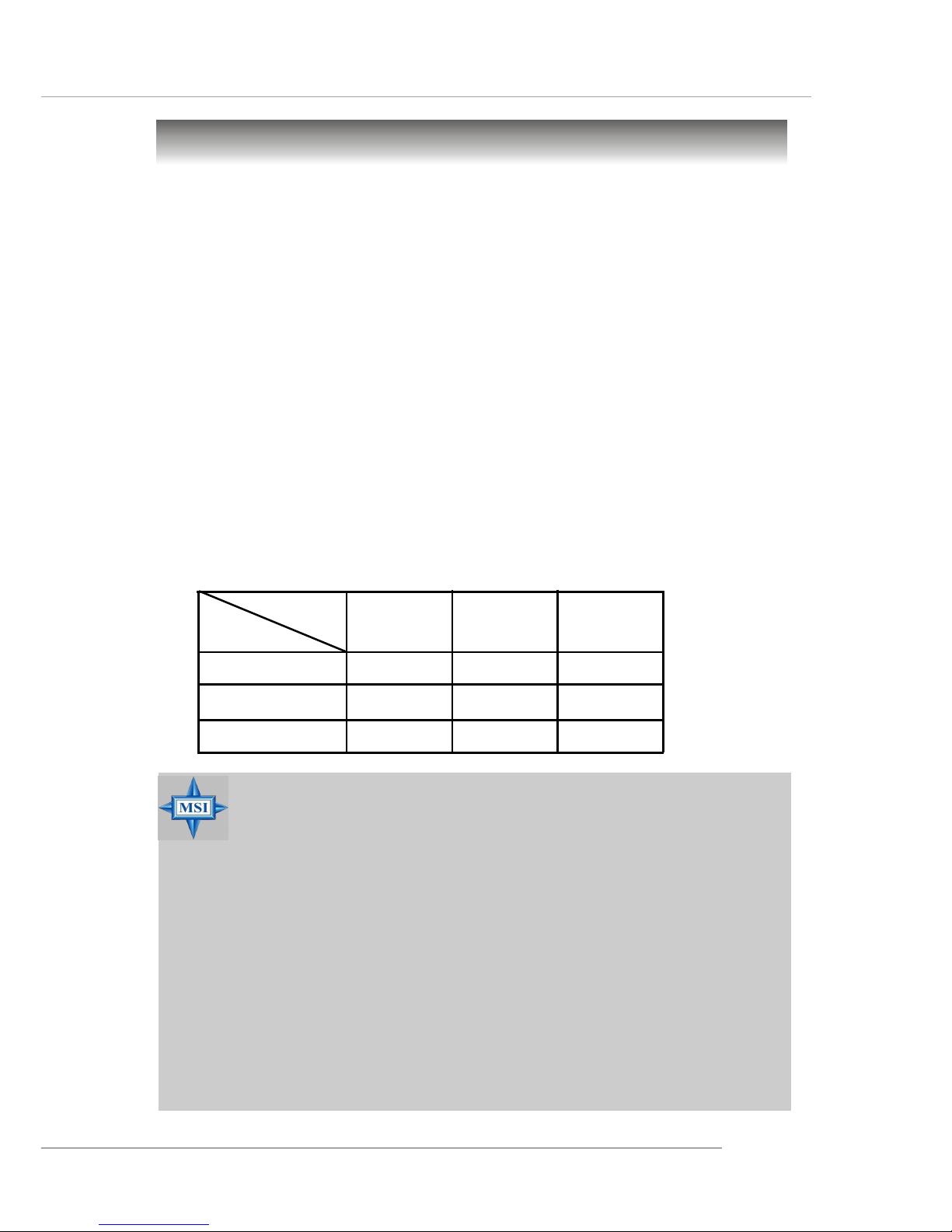
Memory Speed/CPU FSB Support Matrix
FSB
Memory
DDR 266
400 MHz
DDR 333 DDR 400
533 MHz
800 MHz
N/A
OKOK
OKOK
OK
OKOK
OKOK
OK
OK
N/A
OKOK
OKOK
OK
OKOK
OKOK
OK
OKOK
OKOK
OK
OKOK
OKOK
OK
Page 38
2-4
MS-6799 ATX Mainboard
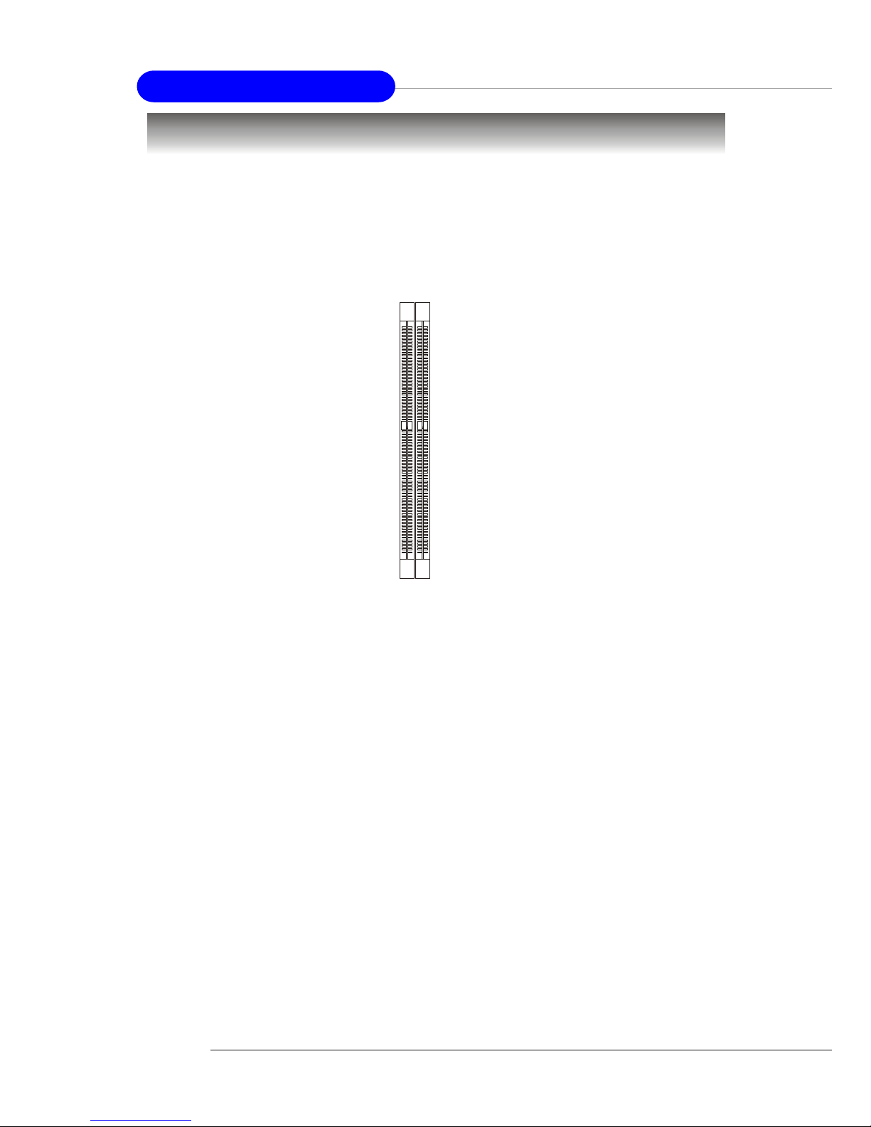
Memory
DIMM1-2
The mainboard provides 2 slots for 184-pin, 2.5V DDR DIMM modules
and supports the memory size up to 2 GB without ECC,. Y ou can install DDR266/
DDR333/DDR400 DDR SDRAM modules on the DDR DIMM slots. T o operate
properly, at least one DIMM module must be installed.
Introduction to DDR SDRAM
DDR (Double Data Rate) SDRAM is similar to conventional SDRAM,
but doubles the rate by transferring data twice per cycle. It uses 2.5 volts as
opposed to 3.3 volts used in SDR SDRAM, and requires 184-pin DIMM modules rather than 168-pin DIMM modules used by SDR SDRAM. Three types of
DDR are available at the time of writing: DDR266, DDR333 & DDR400. DDR266
DDR SDRAM running at 133MHz will produce about 1.6GB/s memory
bandwidth. DDR333 running at 166MHz will produce 2.1GB/s memory
bandwidth. DDR400 is also available with bandwidith up to 3.2GB/s for singlechannel mode or with 6.4GB/s for dual-channel mode. High memory bandwidth makes DDR an ideal solution for high performance PC, workstations and
servers.
DDR DIMM Module Combination
Install at least one DIMM module on the slots. Memory modules can be
installed on the slots in any order . You can install either single- or double-side
modules to meet your own needs.
Page 39
2-5
Hardware Setup
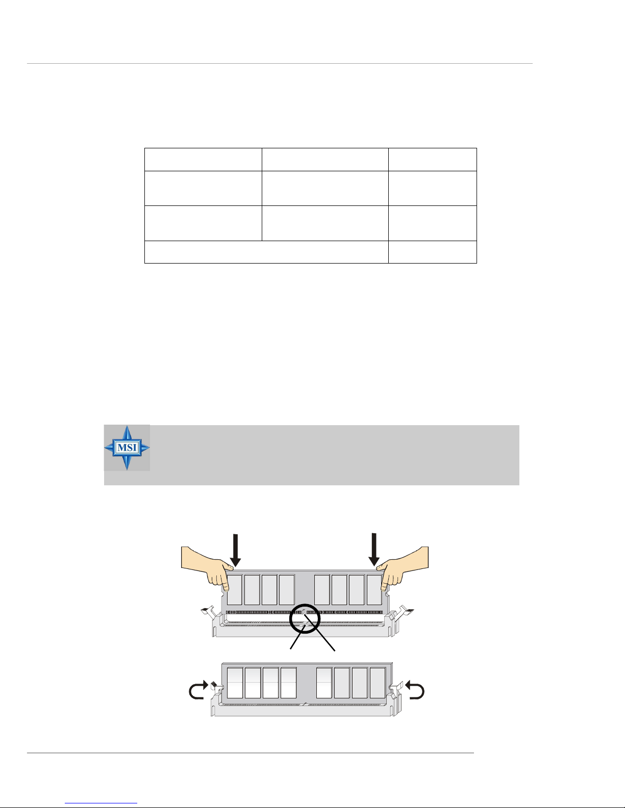
Installing DDR Modules
1. The DDR DIMM has only one notch on the center of module. The module
will only fit in the right orientation.
2. Insert the DIMM memory module vertically into the DIMM slot. Then
push it in until the golden finger on the memory module is deeply inserted
in the socket.
3. The plastic clip at each side of the DIMM slot will automatically close.
MSI Reminds Y ou...
You can barely see the golden finger if the module is properly
inserted in the socket.
Volt
Notch
Memory modules can be installed in any combination as follows:
S: Single Side D: Double Side
Slot Memory Module Total Memory
DIMM 1
(Bank 0 & 1)
S/D 64MB~1GB
DIMM 2
(Bank 2 & 3)
S/D 64MB~1GB
Maximum System Memory Supported
64MB~2GB
Page 40
2-6
MS-6799 ATX Mainboard
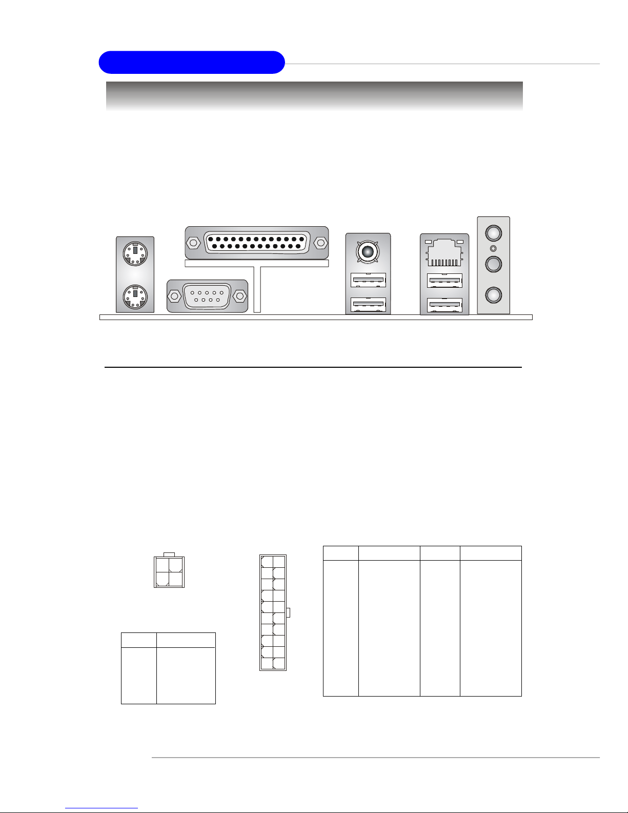
The back panel provides the following connectors:
Back Panel / Power Supply
Mouse
Parallel
COM A
USB Ports
Keyboard
L-out
L-in
MIC
LAN
(Optional)
USB Ports
SPDIF-Out
A TX 20-Pin Power Connector: A TX1
This connector allows you to connect to an ATX power supply. To
connect to the ATX power supply, make sure the plug of the power supply is
inserted in the proper orientation and the pins are aligned. Then push down
the power supply firmly into the connector.
A TX 12V Power Connector: JPW1
This 12V power connector is used to provide power to the CPU.
PIN SIGNAL
1 GND
2 GND
3 12V
4 12V
JPW1 Pin Definition
PIN SIGNAL
11 3.3V
12 -12V
13 GND
14 PS_ON
15 GND
16 GND
17 GND
18 -5V
19 5V
20 5V
PIN SIGNAL
1 3.3V
2 3.3V
3 GND
45V
5 GND
65V
7 GND
8 PW_OK
9 5V_SB
10 12V
ATX1 Pin Definition
JPW1
1
3
4
2
ATX1
10
1
20
11
Page 41
2-7
Hardware Setup
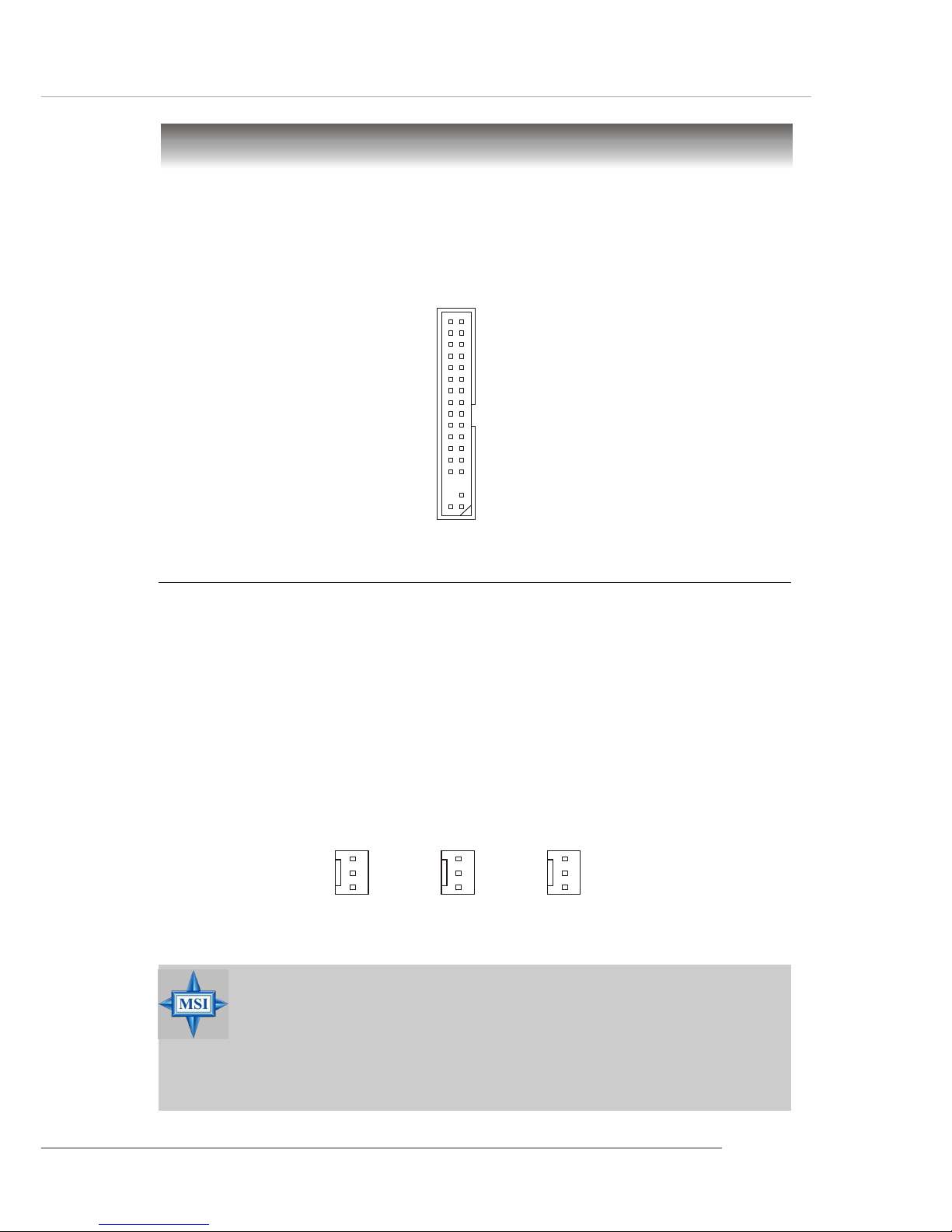
Floppy Disk Drive Connector: FDD1
The mainboard provides a standard floppy disk drive connector that
supports 360K, 720K, 1.2M, 1.44M and 2.88M floppy disk types.
Connectors
FDD1
Fan Power Connectors: CF AN1/SF AN1/SF AN2
The CPUF AN1 (processor fan), SF AN1, and SFAN2 (system fan) support
system cooling fan with +12V. When connecting the wire to the connectors,
always take note that the red wire is the positive and should be connected to
the +12V, the black wire is Ground and should be connected to GND. If the
mainboard has a System Hardware Monitor chipset on-board, you must use a
specially designed fan with speed sensor to take advantage of the CPU fan
control.
MSI Reminds Y ou...
1. Always consult the vendors for proper CPU cooling fan.
2. CFAN1 supports the fan contr ol. You can install the PC Alert
utility that will automatically control the CPU fan speed
according to the actual CPU temperature.
CF AN1
Sensor
+12V
GND
SF AN1
Sensor
+12V
GND
SF AN2
(Optional)
Sensor
+12V
GND
Page 42
2-8
MS-6799 ATX Mainboard
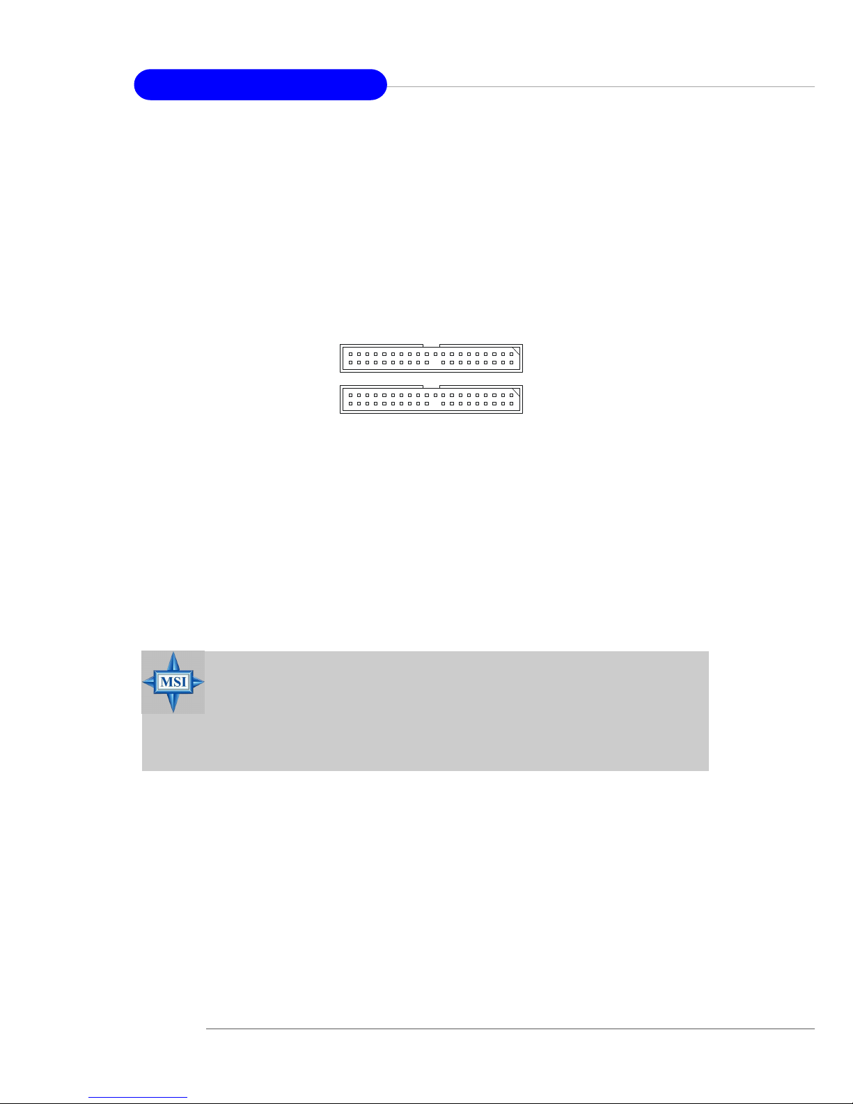
AT A133 Hard Disk Connectors: IDE1 & IDE2
The mainboard has a 32-bit Enhanced PCI IDE and Ultra DMA 33/66/100/
133 controller that provides PIO mode 0~5, Bus Master, and Ultra DMA 33/66/
100/133 function. Y ou can connect up to four hard disk drives, CD-ROM, 120MB
Floppy and other devices. These connectors support the provided IDE hard
disk cable.
IDE1 (Primary IDE Connector)
The first hard drive should always be connected to IDE1. IDE1 can connect a
Master and a Slave drive. You must configure second hard drive to Slave mode
by setting the jumper accordingly.
IDE2 (Secondary IDE Connector)
IDE2 can also connect a Master and a Slave drive.
MSI Reminds Y ou...
If you install two hard disks on cable, you must configure the
second drive to Slave mode by setting its jumper. Refer to the
hard disk documentation supplied by hard disk vendors for
jumper setting instructions.
IDE1
IDE2
Page 43
2-9
Hardware Setup
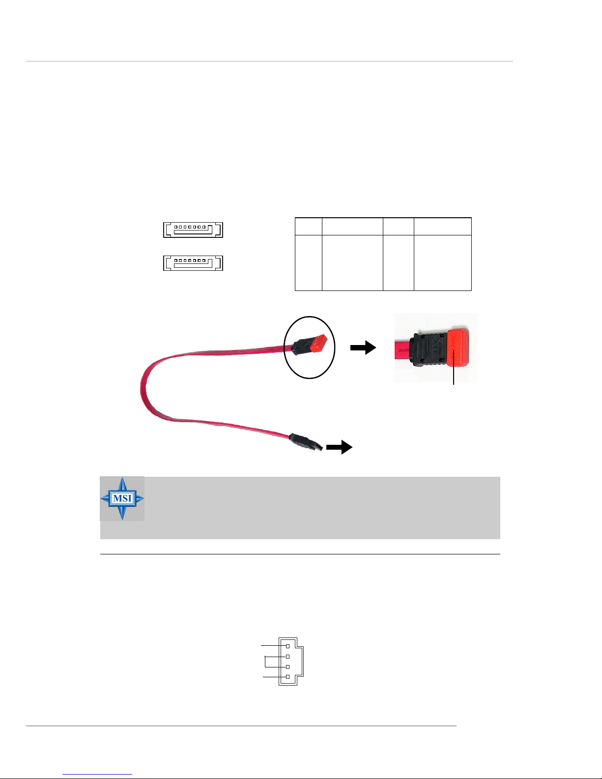
Serial A TA HDD Connectors: SA TA1, SA TA2 (Optional)
The mainboard provides dual high-speed Serial ATA interface ports.
The ports support 1st generation Serial ATA data rates of 150MB/s and are
fully compliant with Serial AT A 1.0 specifications. Each Serial ATA connector
can connect to 1 hard disk drive.
PIN SIGNAL PIN SIGNAL
1 GND 2 TXP
3 TXN 4 GND
5 RXN 6 RXP
7 GND
Pin Definition
Connect to SATA1 or SATA2
Take out the dust cover and
connect to the hard disk
devices
Optional Serial A TA cable
MSI Reminds Y ou...
Please do not fold the Serial ATA cable into 90-degree angle.
Otherwise, the loss of data may occur during transmission.
SATA2
SATA1
7 1
CD-In Connector: CD1
The connector is for CD-ROM audio connector.
CD1
GND
L
R
Page 44
2-10
MS-6799 ATX Mainboard
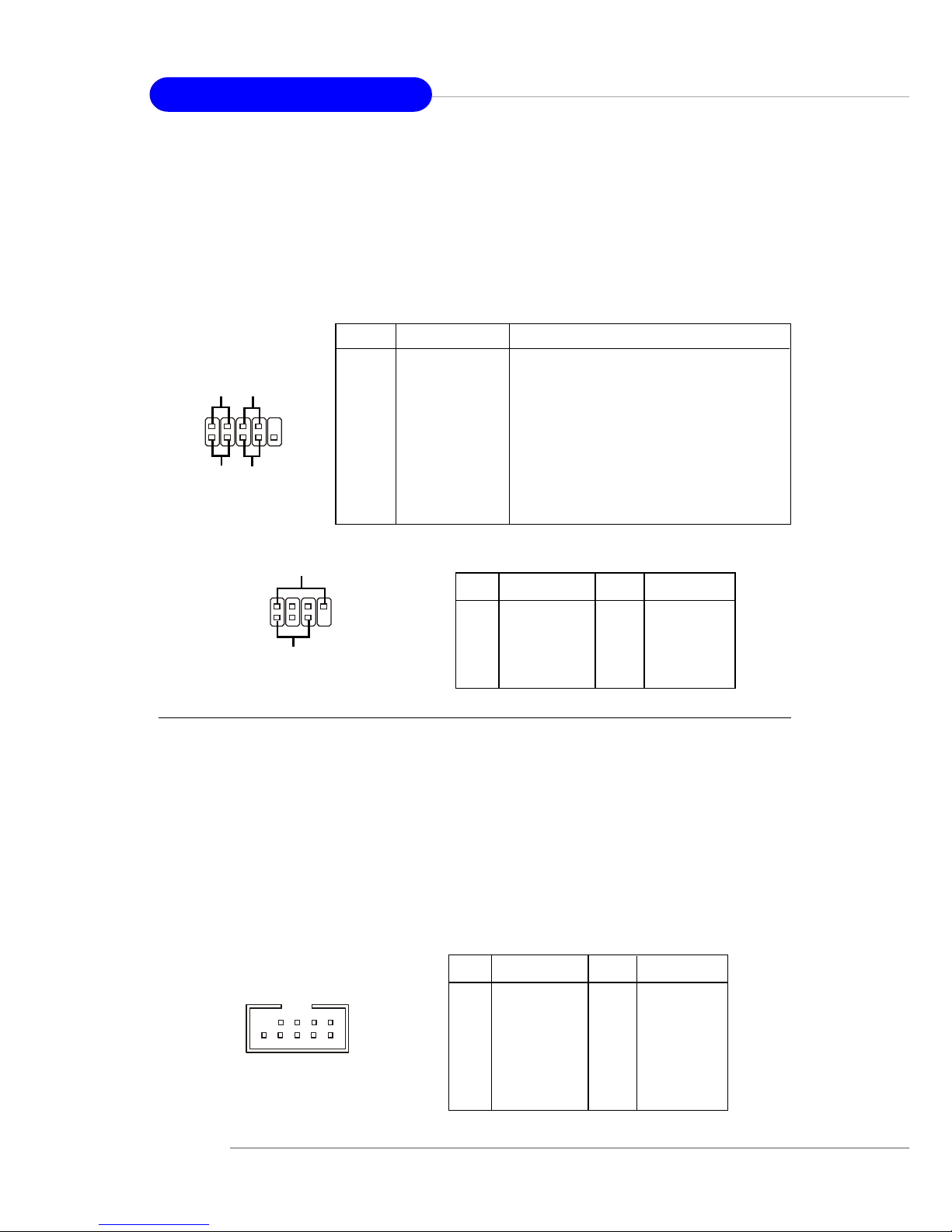
Front Panel Connectors: JFP1 & JFP2
The mainboard provides two front panel connectors for electrical
connection to the front panel switches and LEDs. JFP1 is compliant with Intel
®
Front Panel I/O Connectivity Design Guide.
Power
LED
Speaker
1
2
7
8
JFP2
PIN SIGNAL DESCRIPTION
1 HD_LED_P Hard disk LED pull-up
2 FP PWR/SLP MSG LED pull-up
3 HD_LED_N Hard disk active LED
4 FP PWR/SLP MSG LED pull-up
5 RST_SW_N Reset Switch low reference pull-down to GND
6 PWR_SW_P Power Switch high reference pull-up
7 RST_SW_P Reset Switch high reference pull-up
8 PWR_SW_N Power Switch low reference pull-down to GND
9 RSVD_DNU Reserved. Do not use.
JFP1 Pin Definition
PIN SIGNAL PIN SIGNAL
1 GND 2 SPK3 SLED 4 BUZ+
5 PLED 6 BUZ7 NC 8 SPK+
JFP2 Pin Definition
PIN SIGNAL PIN SIGNAL
1 VCC 2 VCC
3 USB0- 4 USB15 USB0+ 6 USB1+
7 GND 8 GND
9 Key (no pin) 10 USBOC
Pin Definition
1
2
9
JUSB1 / JUSB2
Front USB Connectors: JUSB1 & JUSB2
The mainboard provides two USB 2.0 pin headers JUSB1 & JUSB2 that
are compliant with Intel® I/O Connectivity Design Guide. USB 2.0 technology
increases data transfer rate up to a maximum throughput of 480Mbps, which is
40 times faster than USB 1.1, and is ideal for connecting high-speed USB
interface peripherals such as USB HDD, digital cameras, MP3 players,
printers, modems and the like.
9
1
2
10
JFP1
HDD
LED
Reset
Switch
Power
LED
Power
Switch
10
Page 45
2-11
Hardware Setup
Front Panel Audio Connector: JAUD1
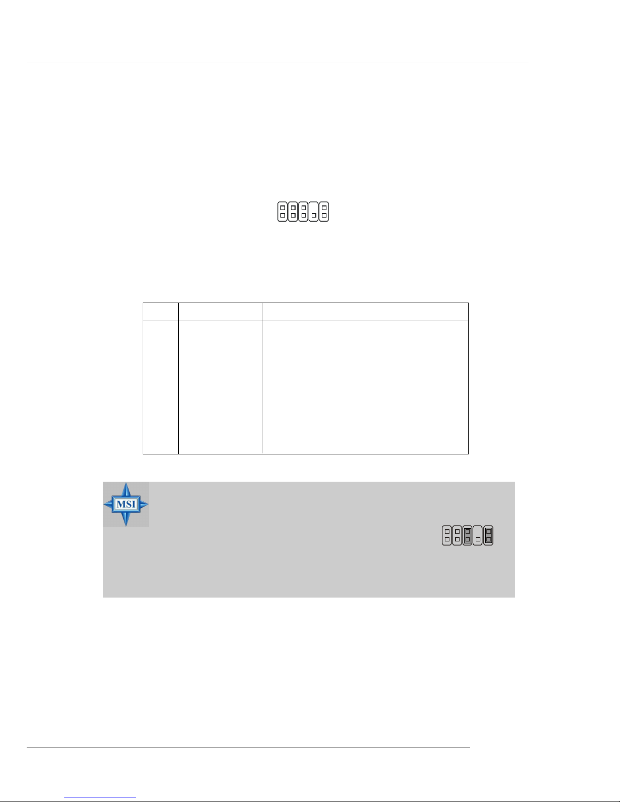
The JAUD1 front panel audio connector allows you to connect to the
front panel audio and is compliant with Intel® Front Panel I/O Connectivity
Design Guide.
JAUD1
1
2
9
10
PIN SIGNAL DESCRIPTION
1 AUD_MIC Front panel microphone input signal
2 AUD_GND Ground used by analog audio circuits
3 AUD_MIC_BIAS Microphone power
4 AUD_VCC Filtered +5V used by analog audio circuits
5 AUD_FPOUT_R Right channel audio signal to front panel
6 AUD_RET_R Right channel audio signal return from front panel
7 HP_ON Reserved for future use to control headphone amplifier
8 KEY No pin
9 AUD_FPOUT_L Left channel audio signal to front panel
10 AUD_RET_L Left channel audio signal return from front panel
JAUD1 Pin Definition
MSI Reminds Y ou...
If you don’t want to connect to the front audio
header, pins 5 & 6, 9 & 10 have to be jumpered in
order to have signal output directed to the rear
audio ports. Otherwise, the Line-Out connector on
the back panel will not function.
5
6
10
9
Page 46
2-12
MS-6799 ATX Mainboard
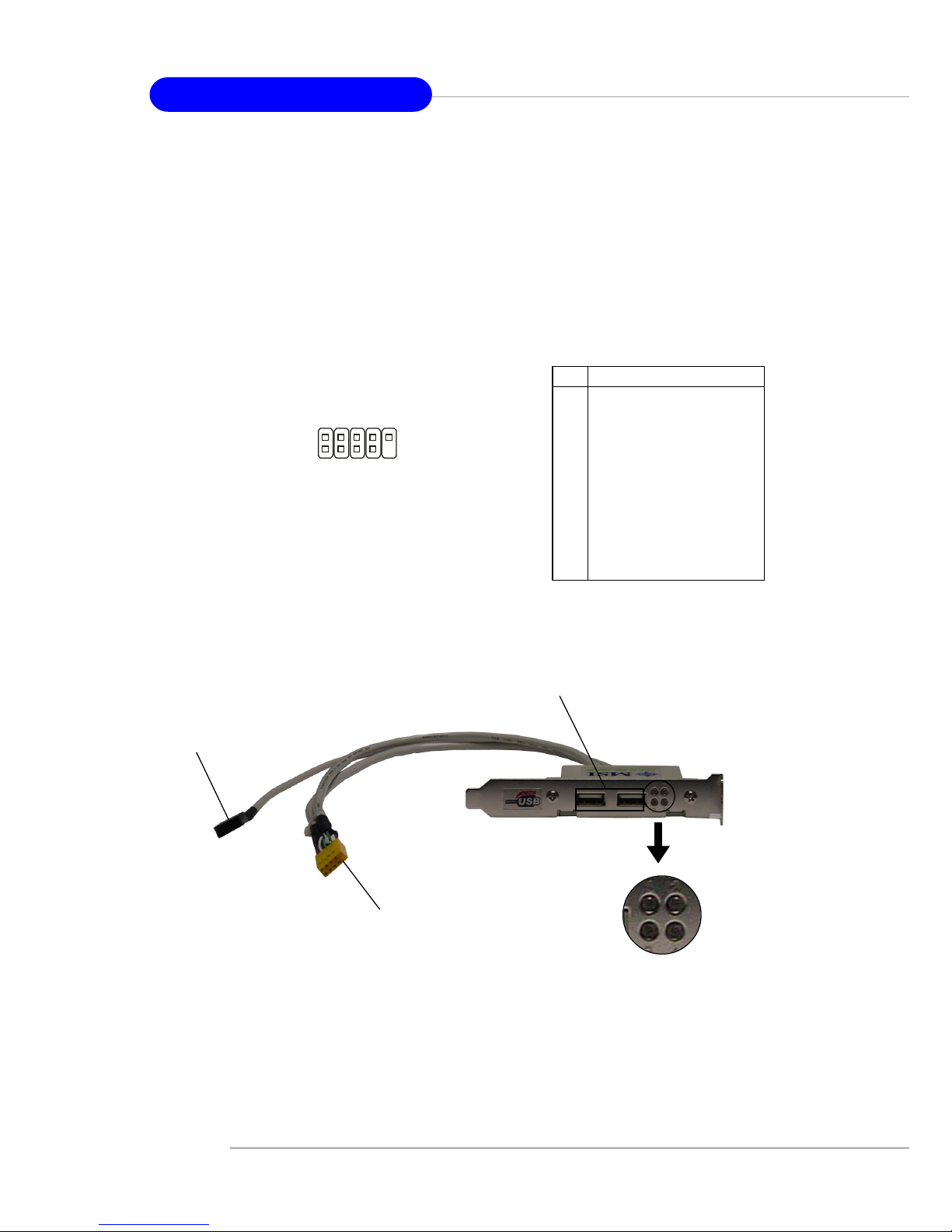
D-Bracket™ 2 Connector: JDB1
The mainboard comes with a JDB1 connector for you to connect to DBracket™ 2. D-Bracket™ 2 is a USB Bracket that supports both USB1.1 & 2.0
spec. It integrates four LEDs and allows users to identify system problem
through 16 various combinations of LED signals. For definitions of 16 signal
combinations, please refer to D-Bracket™ 2 in Chapter 1.
D-Bracket™ 2
Connected to JUSB2 (the USB
pinheader in yellow color)
Connected to JDB1
LEDs
Depending on the optional bracket you buy, please
note there might be a Bluetooth Sticker to cover one of
the port, which marks “Do no remove, when using
bluetooth”.
Pin Signal
1 DBG1 (high for green color)
2 DBR1 (high for red color)
3 DBG2 (high for green color)
4 DBR2 (high for red color)
5 DBG3 (high for green color)
6 DBR3 (high for red color)
7 DBG4 (high for green color)
8 DBR4 (high for red color)
9 Key
10 NC
JDB1 Pin Definition
JDB1
1
9
2
10
Page 47
2-13
Hardware Setup
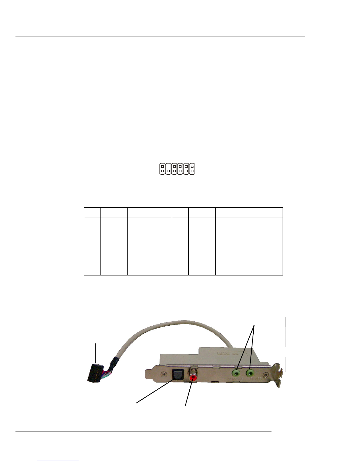
JSP1
1 11
12 2
PIN SIGNAL DESCRIPTION PIN SIGNAL DESCRIPTION
1 VCC5 VCC 5V 2 VDD3 VDD 3.3V
3 SPDFO S/PDIF output 4 (No Pin) K e y
5 GND Ground 6 SPDFI S/PDIF input
7 LFE-OUT Audio bass output 8 SOUT-R Audio right surrounding output
9 CET-OUT Audio center output 1 0 SOUT-L Audio left surrounding output
11 GND Ground 12 GND Ground
JSP1 Pin Definition
Optional S-Bracket
SPDIF jack (optical)
SPDIF jack (coaxial)
Analog Line-Out jack
Connect to JSP1
S-Bracket (SPDIF) Connector: JSP1 (Optional)
The connector allows you to connect a S-Bracket for Sony & Philips
Digital Interface (SPDIF). The S-Bracket offers 2 SPDIF jacks for digital audio
transmission (one for optical fiber connection and the other for coaxial), and 2
analog Line-Out jacks for 4-channel audio output.
T o attach the fiber-optic cable to optical SPDIF jack, you need to remove
the plug from the jack first. The two SPDIF jacks support SPDIF output only.
For more information on the S-Bracket, refer to Appendix: Using 4- or 6-Channel
Audio Function.
Page 48
2-14
MS-6799 ATX Mainboard
The motherboard provides the following jumpers for you to set the
computer’s function. This section will explain how to change your
motherboard’s function through the use of jumpers.
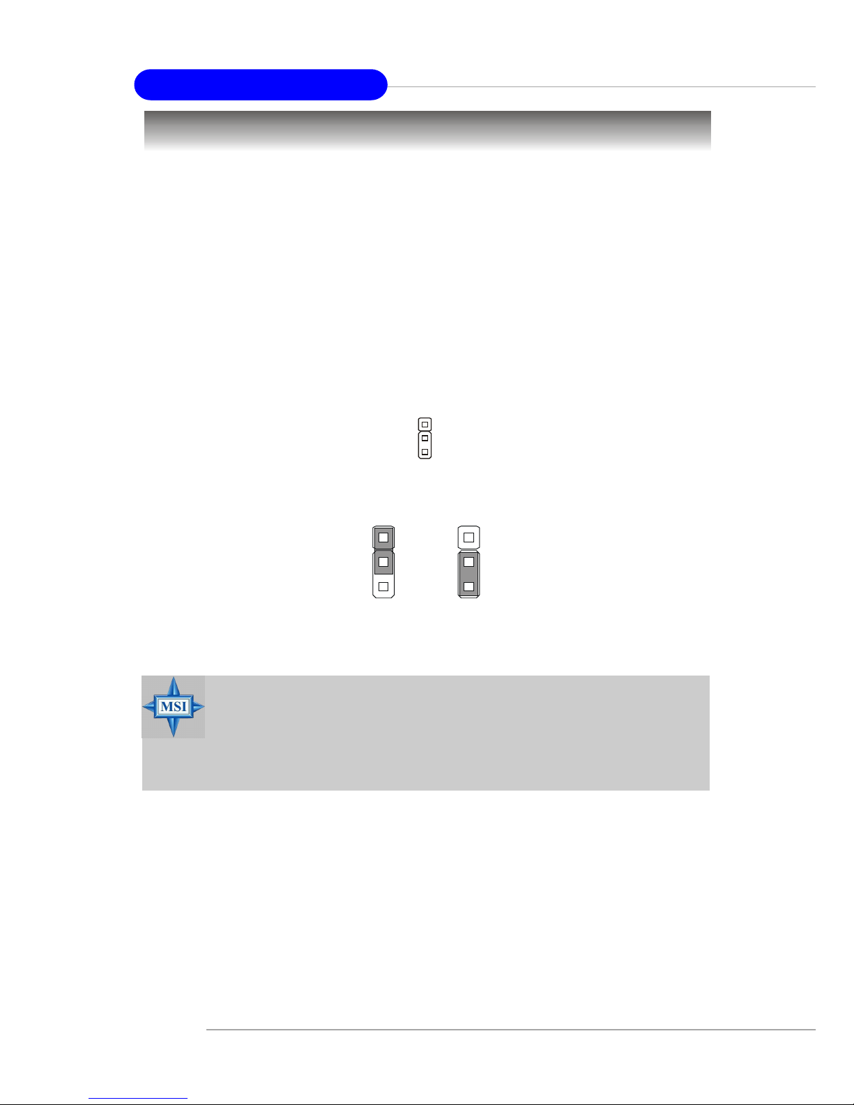
Clear CMOS Jumper: JBA T1
There is a CMOS RAM on board that has a power supply from external
battery to keep the data of system configuration. With the CMOS RAM, the
system can automatically boot OS every time it is turned on. If you want to
clear the system configuration, use the JBAT1 (Clear CMOS Jumper ) to clear
data. Follow the instructions below to clear the data:
Jumpers
MSI Reminds Y ou...
You can clear CMOS by shorting 2-3 pin while the system is off.
Then return to 1-2 pin position. Avoid clearing the CMOS while
the system is on; it will damage the mainboard.
JBAT1
1
Clear Data
1
3
Keep Data
1
3
Page 49
2-15
Hardware Setup
Order 1 Order 2 Order 3 Order 4
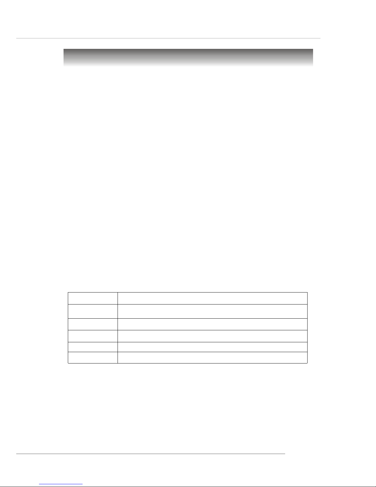
PCI Slot 1 INT A# INT B# INT C# INT D#
PCI Slot 2 INT B# INT C# INT D# INT A#
PCI Slot 3 INT C# INT D# INT A# INT B#
PCI Slot 4 INT D# INT A# INT B# INT C#
PCI Slot 5 INT A# INT B# INT C# INT D#
Slots
The motherboard provides one AGP slot and five 32-bit PCI bus slots.
AGP (Accelerated Graphics Port) Slot
The AGP slot allows you to insert the AGP graphics card. AGP is an
interface specification designed for the throughput demands of 3D graphics.
It introduces a 66MHz, 32-bit channel for the graphics controller to directly
access main memory. The slot supports 8x/4x AGP card.
PCI (Peripheral Component Interconnect) Slots
The PCI slots allow you to insert the expansion cards to meet your needs.
When adding or removing expansion cards, make sure that you unplug the
power supply first. Meanwhile, read the documentation for the expansion card
to make any necessary hardware or software settings for the expansion card,
such as jumpers, switches or BIOS configuration.
PCI Interrupt Request Routing
The IRQ, acronym of interrupt request line and pronounced I-R-Q, are
hardware lines over which devices can send interrupt signals to the
microprocessor. The PCI IRQ pins are typically connected to the PCI bus INT
A# ~ INT D# pins as follows:
Page 50

3-1
BIOS Setup
Chapter 3. BIOS Setup
This chapter provides information on the BIOS Setup program
and allows you to configure the system for optimum use.
You may need to run the Setup program when:
An error message appears on the screen during the system
booting up, and requests you to run SETUP.
You want to change the default settings for customized
features.
BIOS Setup
Page 51
3-2
MS-6799 ATX Mainboard
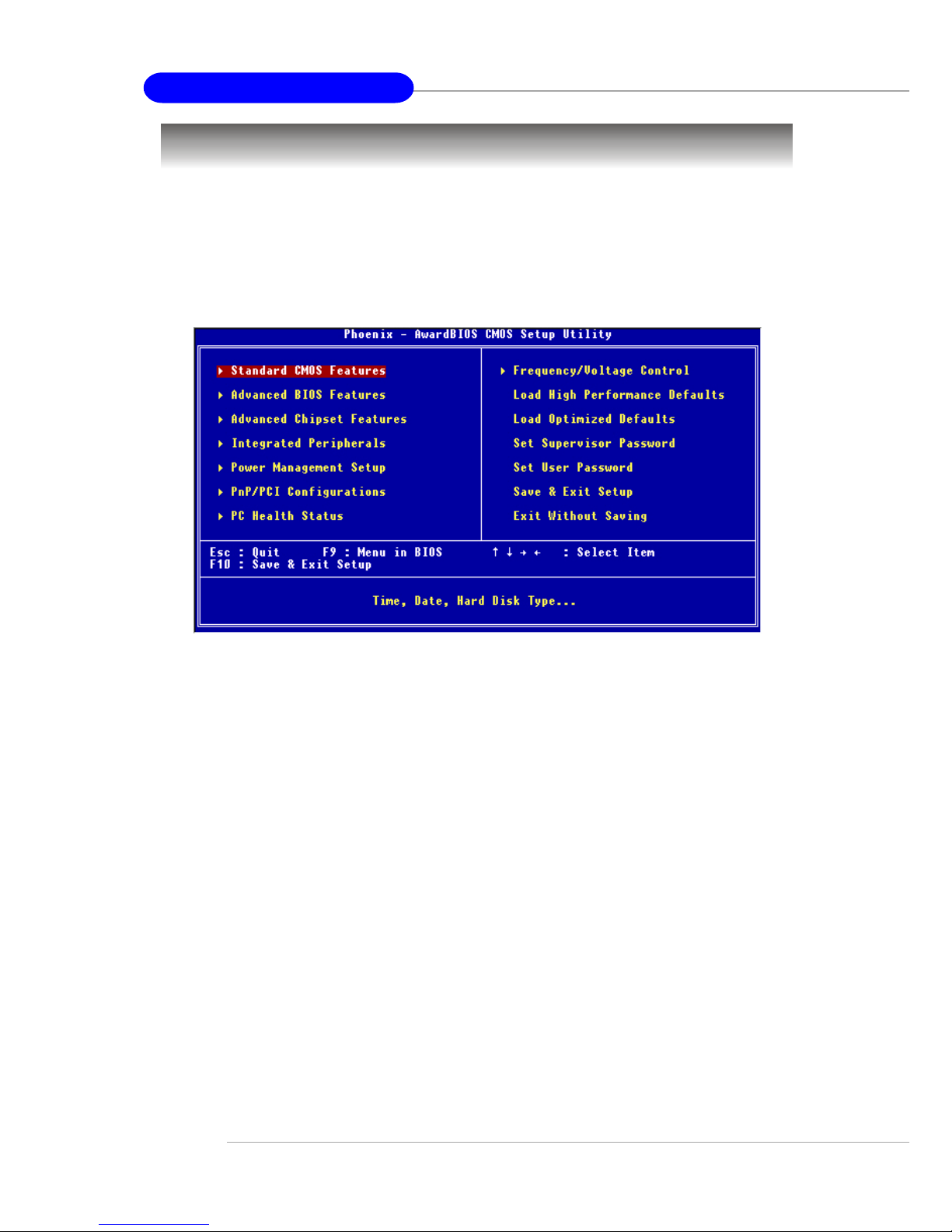
The Main Menu
Standard CMOS Features
Use this menu for basic system configurations, such as time, date etc.
Advanced BIOS Features
Use this menu to setup the items of special enhanced features.
Advanced Chipset Features
Use this menu to change the values in the chipset registers and optimize your
system’s performance.
Integrated Peripherals
Use this menu to specify your settings for integrated peripherals.
Power Management Setup
Use this menu to specify your settings for power management.
PnP/PCI Configurations
This entry appears if your system supports PnP/PCI.
Once you enter Phoenix-Award® BIOS CMOS Setup Utility, the Main Menu
(Figure 1) will appear on the screen. The Main Menu allows you to select
from twelve setup functions and two exit choices. Use arrow keys to select
among the items and press <Enter> to accept or enter the sub-menu.
Page 52

3-3
BIOS Setup
PC Health Status
This entry shows your PC health status.
Frequency/Voltage Control
Use this menu to specify your settings for frequency/voltage control.
Load High Performance Defaults
Use this menu to load the BIOS values for the best system performance, but
the system stability may be affected.
Load Optimized Defaults
Use this menu to load factory default settings into the BIOS for stable system
performance operations.
Set Supervisor Password
Use this menu to set Supervisor Password.
Set User Password
Use this menu to set User Password.
Save & Exit Setup
Save changes to CMOS and exit setup.
Exit Without Saving
Abandon all changes and exit setup.
Page 53
3-4
MS-6799 ATX Mainboard
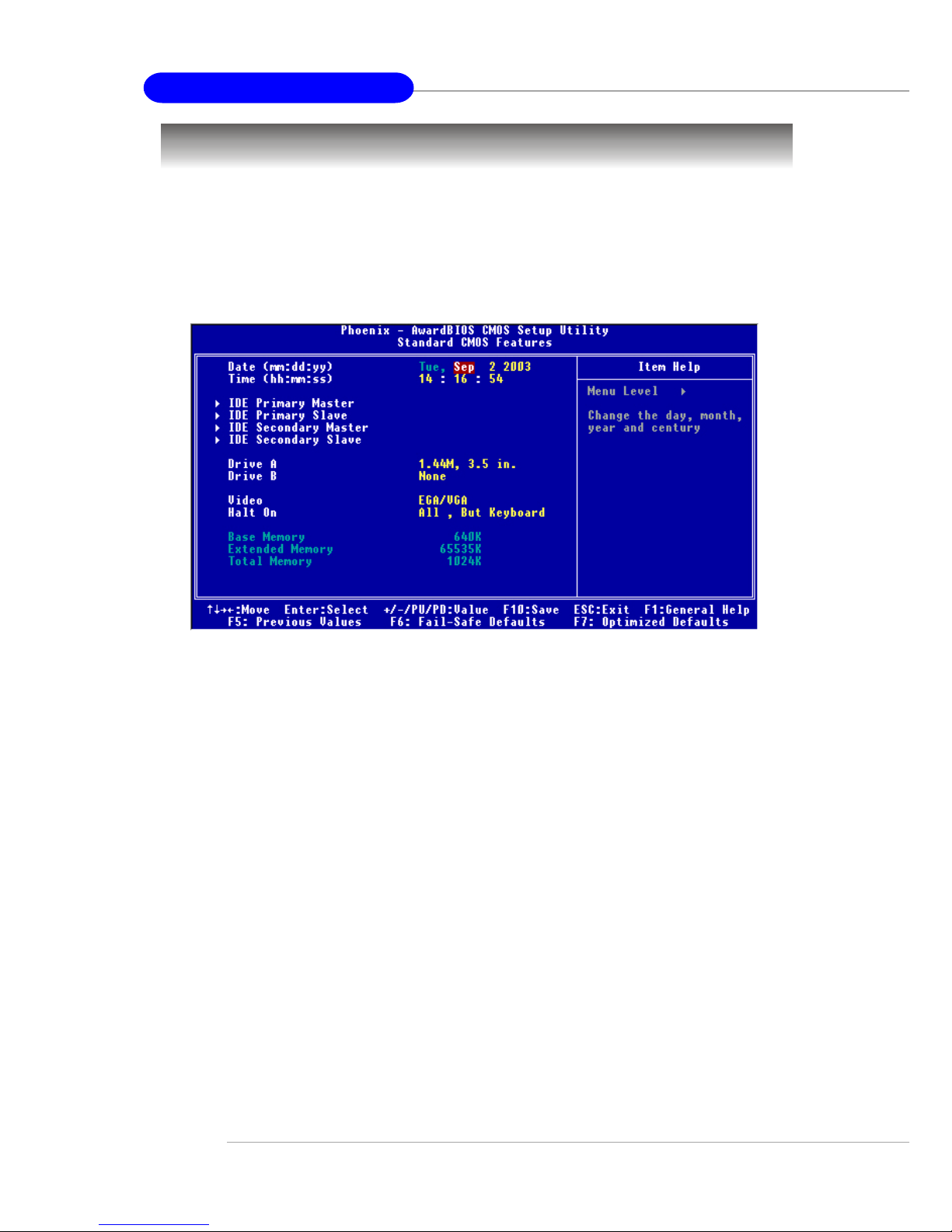
Standard CMOS Features
Date
This allows you to set the system to the date that you want (usually the current
date). The format is <day><month> <date> <year>.
day Day of the week, from Sun to Sat, determined by
BIOS. Read-only.
month The month from Jan. through Dec.
date The date from 1 to 31 can be keyed by numeric
function keys.
year The year can be adjusted by users.
Time
This allows you to set the system time that you want (usually the current
time). The time format is <hour> <minute> <second>.
IDE Primary/Secondary Master/Slave
Press PgUp/<+> or PgDn/<-> to select Manual, None or Auto type. Note that
the specifications of your drive must match with the drive table. The hard disk
will not work properly if you enter improper information for this category. If
The items in Standard CMOS Features Menu are divided into 11 categories.
Each category includes no, one or more than one setup items. Use the arrow
keys to highlight the item and then use the <PgUp> or <PgDn> keys to select
the value you want in each item.
Page 54

3-5
BIOS Setup
your hard disk drive type is not matched or listed, you can use Manual to
define your own drive type manually.
If you select Manual, related information is asked to be entered to the following items. Enter the information directly from the keyboard. This information
should be provided in the documentation from your hard disk vendor or the
system manufacturer.
Access Mode The settings are CHS, LBA, Large, Auto.
Capacity The formatted size of the storage device.
Cylinder Number of cylinders.
Head Number of heads.
Precomp Write precompensation.
Landing Zone Cylinder location of the landing zone.
Sector Number of sectors.
Drive A:/B:
This item allows you to set the type of floppy drives installed. A vailable options:
None, 360K, 5.25 in., 1.2M, 5.25 in., 720K, 3.5 in., 1.44M, 3.5 in.,
2.88M, 3.5 in..
Video
The setting controls the type of video adapter used for the primary monitor of
the system. Available options: EGA/VGA , CGA 40, CGA 80, MONO.
Halt On
The setting determines whether the system will stop if an error is detected at
boot. Available options are:
All Errors The system stops when any error is detected.
No Errors The system doesn’t stop for any detected error.
All, But Keyboard The system doesn’t stop for a keyboard error.
All, But Diskette The system doesn’t stop for a disk error.
All, But Disk/Key The system doesn’t stop for either a disk or a key-
board error.
Base Memory/Extended Memory/Total Memory
These items show the memory status of your system (read only).
Page 55
3-6
MS-6799 ATX Mainboard
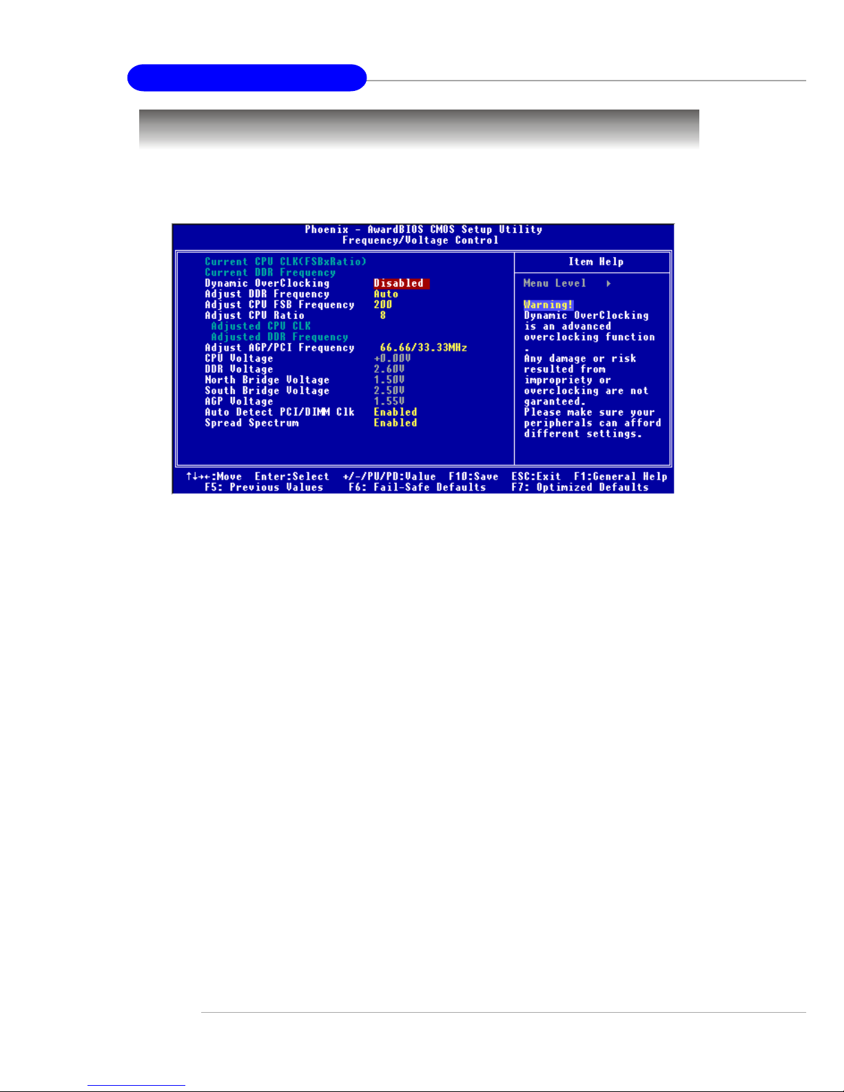
Use this menu to specify your settings for frequency/voltage control.
Frequency/Voltage Control
Dynamic OverClocking
Dynamic Overclocking Technology is the automatic overclocking function,
included in the MSITM’ s newly developed CoreCell
TM
T echnology . It is designed
to detect the load balance of CPU while running programs, and to adjust the
best CPU frequency automatically. When the motherboard detects CPU is
running programs, it will speed up CPU automatically to make the program
run smoothly and faster. When the CPU is temporarily suspending or staying
in the low load balance, it will restore the default settings instead. Usually the
Dynamic Overclocking T echnology will be powered only when users' PC need
to run huge amount of data like 3D games or the video process, and the CPU
frequency need to be boosted up to enhance the overall performance. Setting
options:
Disabled Disable Dynamic Overclocking.
Private 1st level of overclocking.
Sergeant 2nd level of overclocking.
Captain 3rd level of overclocking, also the default value of "Load
High Performance Defaults".
Colonel 4th level of overclocking.
General 5th level of overclocking.
Commander 6th level of overclocking.
Page 56

3-7
BIOS Setup
Adjust DDR Frequency
This item specifies the frequency of DDR SDRAM. Settings are: 266MHz,
333MHz, 400MHz, 433MHz, 450MHz, 466MHz, 500MHz, 533MHz, Auto.
Adjust CPU FSB Frequency
This item specifies the clock frequency of CPU host bus (FSB), AGP (3V66)
and PCI bus. It provides a method for end users to overclock the processor.
Setting options: Give a DEC value by entering a number between maximum
500 MHz to minimum 200 MHz.
Adjust CPU Ratio
This setting controls the ratio of CPU FSB Clock & DRAM Frequency to
enable the CPU & DRAM to run at different frequency combinations. Please
note that the setting options vary according to the CPU FSB Clock preset.
Adjust AGP/PCI Frequency (MHz)
This setting allows you to select the CPU Front Side Bus clock frequency.
Settings: 66.66/33.33Mhz, 66.00/33.00Mhz, 75.40/75.40Mhz, 88.00/44.00Mhz.
CPU Voltage
This item specifies the voltage of CPU Vcore. Note that changing CPU Vcore
could result in unstable system; therefore, it is not recommended to change
MSI Reminds You...
1. Even though the Dynamic Overclocking Technology is more
stable than manual overclocking, basically, it is still risky.
We suggest user to make sure that your CPU can afford to
overclocking regularly first. If you find the PC appears to be
unstable or reboot incidentally, it's better to disable the Dynamic Overclocking or to lower the level of overclocking
options. By the way, if you need to conduct overclocking
manually, you also need to disable the Dynamic OverClocking
first.
2. Meanwhile, there are two functions to protect user's system
from crash.
- There is a safe key "Ins" in BIOS. In case the
overclocking fails, you can pr ess "Ins" key while system
rebooting to restore to the BIOS defaults.
- If the system incidentally reboot for four times, the BIOS
will also be restored to the defaults.
Page 57

3-8
MS-6799 ATX Mainboard
the default setting for long-term purpose. Settings: +0.00V~+0.20V
DDR Voltage
Adjusting the DDR voltage can increase the DDR speed. Any changes made
to this setting may cause a stability issue, so changing the DDR voltage for
long-term purpose is NOT recommended. Settings: 2.50V~2.85V
North Bridge/South Bridge Voltage
These two items specifie the voltage of North Bridge Voltage and South Bridge
Voltage. Any changes made to these settings may cause a stability issue, so
changing the North Bridge/South Bridge Voltage for long-term purpose
is NOT recommended. Settings: 1.50V~1.80V(North), 2.50V~3.00V(South)
AGP Voltage
AGP voltage is adjustable in the field, allowing you to increase the performance of your AGP display card when overclocking, but the stability may be
affected. Settings: 1.50V~2.20V
Auto Detect PCI/DIMM Clk
This option allows you to enable/disable the feature of auto detecting the clock
frequency of the installed PCI bus. The settings are: Enabled, Disabled.
Spread Spectrum
When the motherboard’s clock generator pulses, the extreme values (spikes)
of the pulses creates EMI (Electromagnetic Interference). The Spread Spectrum
function reduces the EMI generated by modulating the pulses so that the spikes
of the pulses are reduced to flatter curves. If you do not have any EMI problem,
leave the setting at Disable for optimal system stability and performance. But
if you are plagued by EMI, set to Enabled for EMI reduction. Remember to
disable Spread Spectrum if you are overclocking because even a slight jitter
can introduce a temporary boost in clock speed which may just cause your
overclocked processor to lock up.
MSI Reminds You...
The settings shown in different color in CPU Volatage, DDR
Voltage, North Bridge/South Bridge Voltage and AGP Voltage
help to verify if your setting is proper for your system.
White: Safe setting.
Yellow: High performance setting.
Red: Not recommended setting and the system may be
unstable.
Page 58
3-9
BIOS Setup
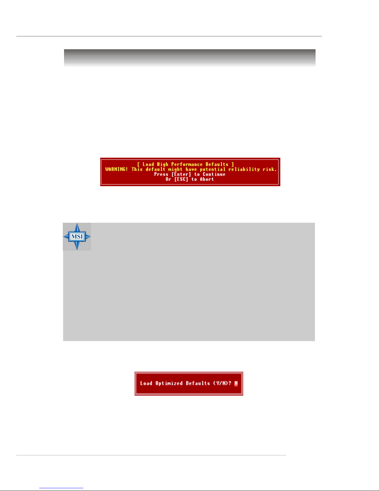
Load High Performance/Optimized Defaults
When you select Load Optimized Defaults, a message as below appears:
Pressing Y loads the default factory settings for optimal system performance.
The two options on the main menu allow users to restore all of the BIOS
settings to High Performance defaults or BIOS Setup defaults. The High Performance Defaults are the values set by the mainboard manufacturer for the
best system performance but probably will cause a stability issue. The BIOS
Setup Defaults are the default values also set by the mainboard manufacturer
for stable performance of the mainboard.
When you select Load High Performance Defaults, a message as below appears:
Pressing ‘Enter’ loads the default BIOS values that enable the best system
performance but may lead to a stability issue.
MSI Reminds You...
The option is for power or overclocking users only. Use of high
performance defaults will tighten most timings to increase the
system performance. Therefor e, a high-end system configuration
is a must, which means you need high-quality VGA adapter, RAM
and so on. We don’t recommend that users should apply the
high performance defaults in their regular systems. Otherwise,
the system may become unstable or even crash. If the system
crashes or hangs after enabling the feature, please CLEAR CMOS
DATA to resolve the problem. For more information, refer to
“Clear CMOS Jumper:JBAT1” in Chapter 2.
Page 59

3-10
MS-6799 ATX Mainboard
Set Supervisor/User Password
MSI Reminds You...
About Supervisor Password & User Password:
Supervisor password: Can enter and change the settings of
the setup menu.
User password: Can only enter but do not have the
right to change the settings of the setup
menu.
When you select this function, a message as below will appear on the screen:
Type the password, up to eight characters in length, and press <Enter>. The
password typed now will replace any previously set password from CMOS
memory. You will be prompted to confirm the password. Retype the password and press <Enter>. You may also press <Esc> to abort the selection and
not enter a password.
To clear a set password, just press <Enter> when you are prompted to enter
the password. A message will show up confirming the password will be
disabled. Once the password is disabled, the system will boot and you can
enter Setup without entering any password.
When a password has been set, you will be prompted to enter it every time
you try to enter Setup. This prevents an unauthorized person from changing
any part of your system configuration.
Additionally, when a password is enabled, you can also have BIOS to request
a password each time the system is booted. This would prevent unauthorized
use of your computer. The setting to determine when the password prompt is
required is the Security Option of the Advanced BIOS Feature menu. If the
Security Option is set to System, the password is required both at boot and at
entry to Setup. If set to Setup, password prompt only occurs when you try to
enter Setup.
Page 60

A-1
Using 4- or 6-Channel Audio Function
Appendix A: Using 2-, 4- & 6-Channel
Audio Function
The mainboard is equipped with Realtek ALC655 chip, which provides
support for 6-channel audio output, including 2 Front, 2 Rear, 1 Center and 1
Subwoofer channel. ALC655 allows the board to attach 4 or 6 speakers for
better surround sound effect. The section will tell you how to install and use
4-/6-channel audio function on the board.
Page 61
A-2
MS-6799 ATX Mainboard
Installing the Audio Driver
You need to install the driver for Realtek ALC655 chip to function properly
before you can get access to 4-/6-channel audio operations. Follow the
procedures described below to install the drivers for different operating systems.
Installation for Windows 98SE/ME/2000/XP
For Windows® 2000, you must install Windows® 2000 Service Pack2 or
later before installing the driver.
The following illustrations are based on Windows® XP environment and
could look slightly different if you install the drivers in different operating
systems.
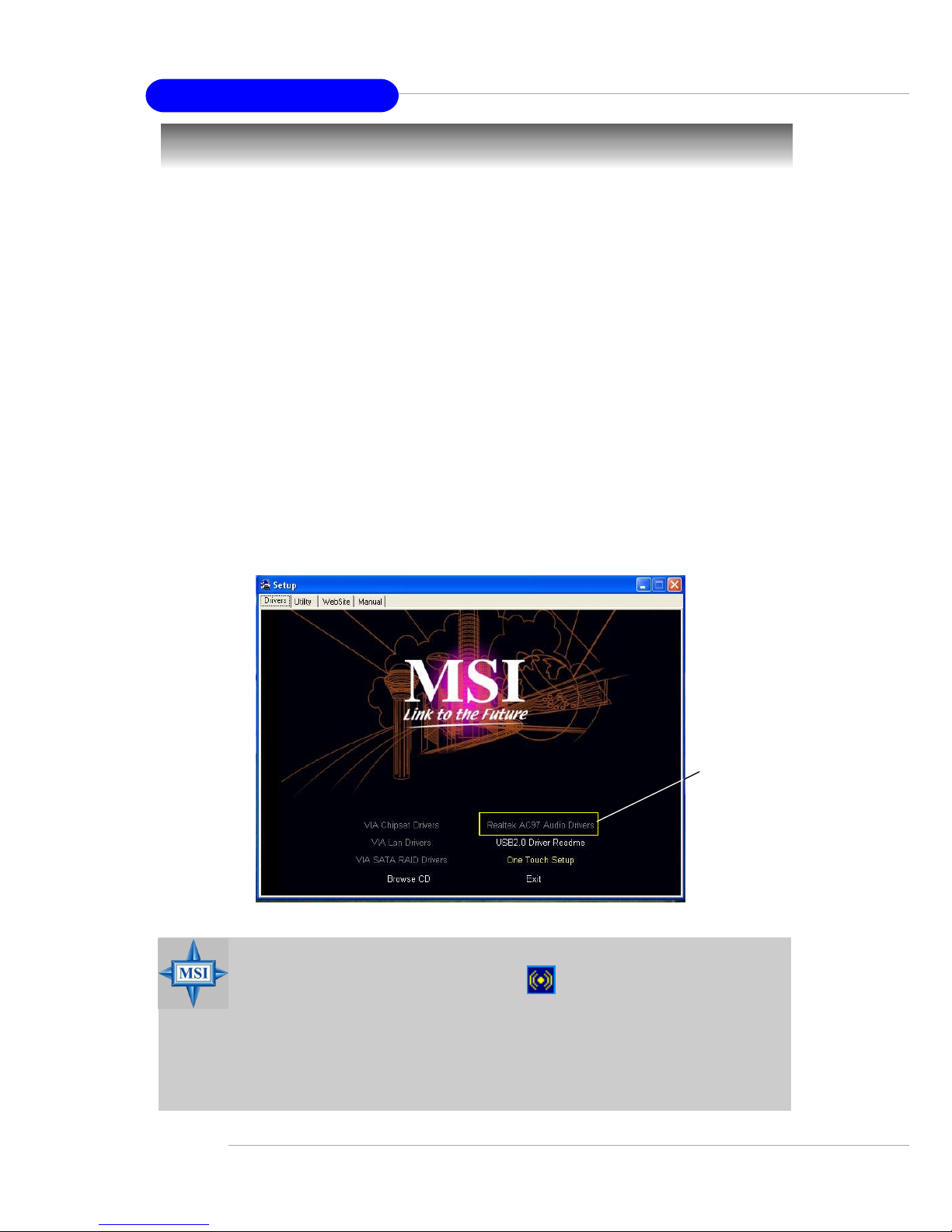
1. Insert the companion CD into the CD-ROM drive. The setup screen will
automatically appear.
2. Click Realtek AC97 Audio Drivers.
MSI Reminds Y ou...
The AC97 Audio Configuration software utility is under
continuous update to enhance audio applications. Hence, the
program screens shown here in this appendix may be slightly
different from the latest software utility and shall be held for
reference only.
Click here
Page 62
A-3
Using 4- or 6-Channel Audio Function
Click here
Click here
Select this
option
4.4.
4.4.
4.
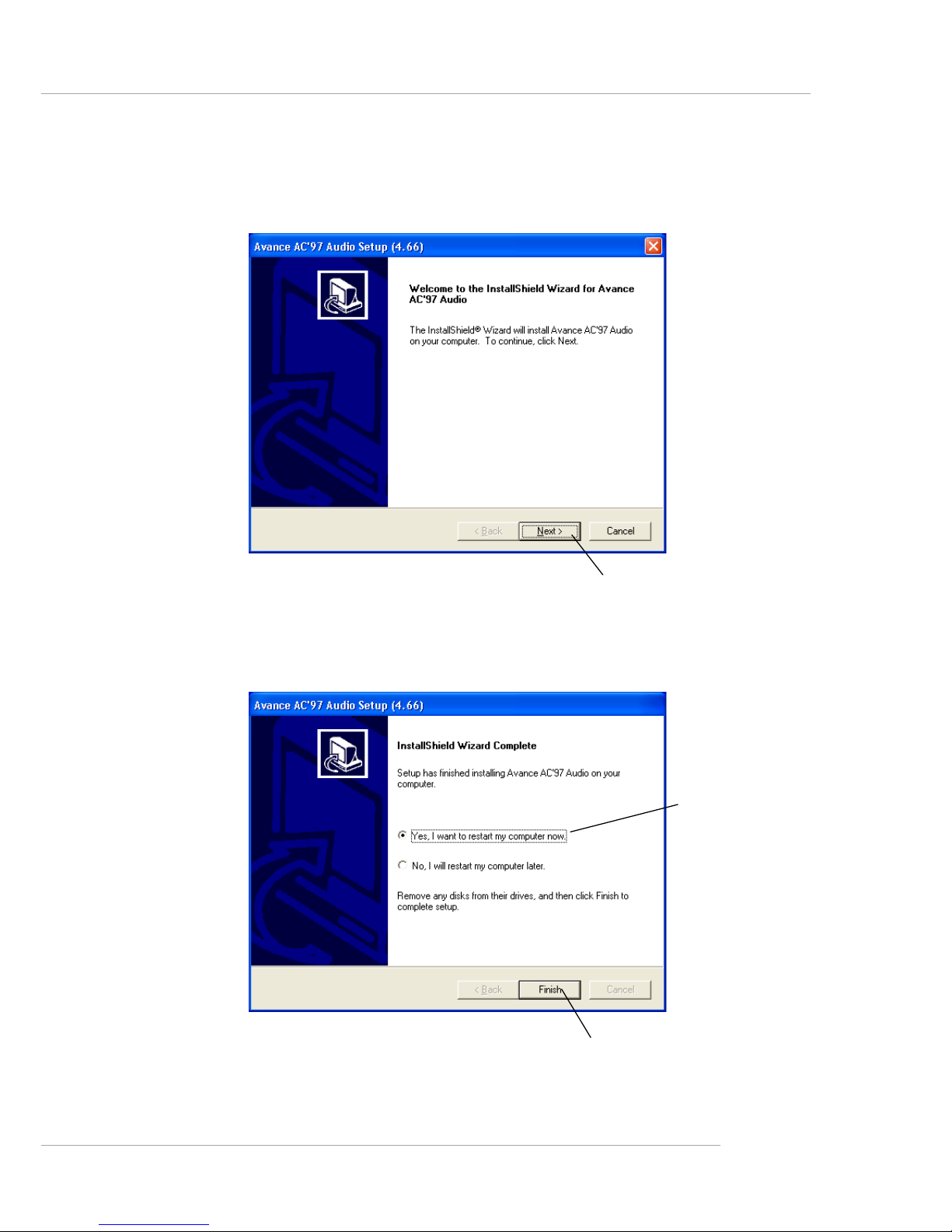
Click Click
Click Click
Click
FinishFinish
FinishFinish
Finish
to restart the system. to restart the system.
to restart the system. to restart the system.
to restart the system.
3.3.
3.3.
3.
Click Click
Click Click
Click
NextNext
NextNext
Next
to install the AC’97 Audio software. to install the AC’97 Audio software.
to install the AC’97 Audio software. to install the AC’97 Audio software.
to install the AC’97 Audio software.
Page 63
A-4
MS-6799 ATX Mainboard
Software Configuration
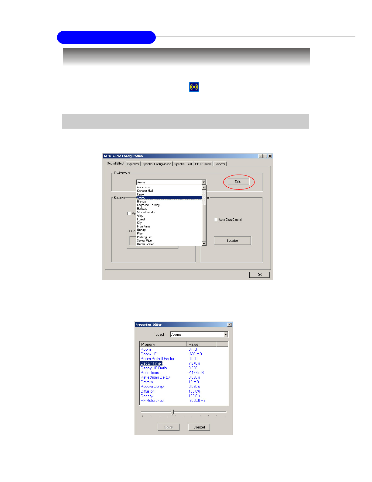
After installing the audio driver, you are able to use the 4-/6-channel
audio feature now. Click the audio icon from the window tray at the lowerright corner of the screen to activate the AC97 Audio Configuration.
Sound Effect
Here you can select a sound effect you like from the Environment list.
You may also edit the properties for an environment as you wish by
clicking the Edit button, then just scroll the bar in the bottom for each property
to adjust.
Page 64
A-5
Using 4- or 6-Channel Audio Function
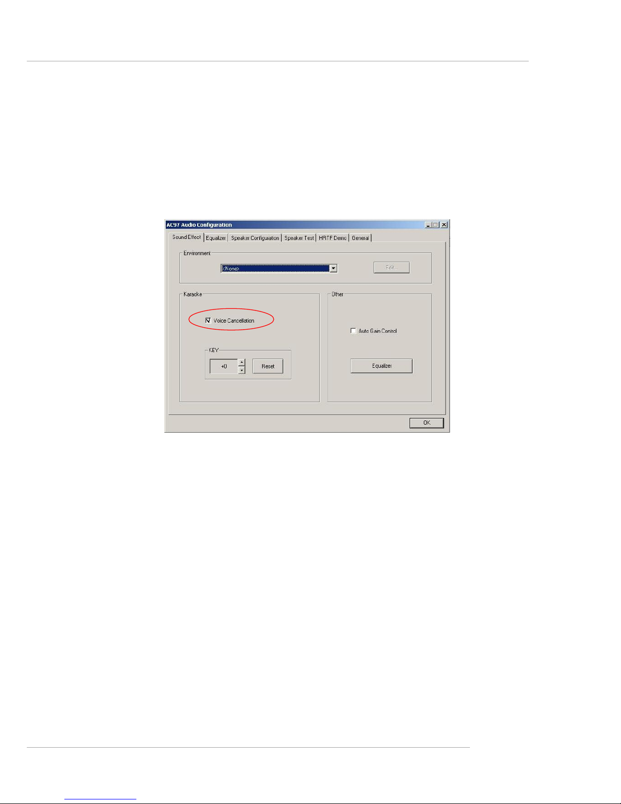
Here it provides the Karaoke function which will automatically remove
human voice (lyrics) and leave melody for you to sing the song. Note that this
function applies only for 2-channel audio operation.
Just check the Voice Cancellation box and then click OK to activate the
Karaoke function.
Page 65
A-6
MS-6799 ATX Mainboard
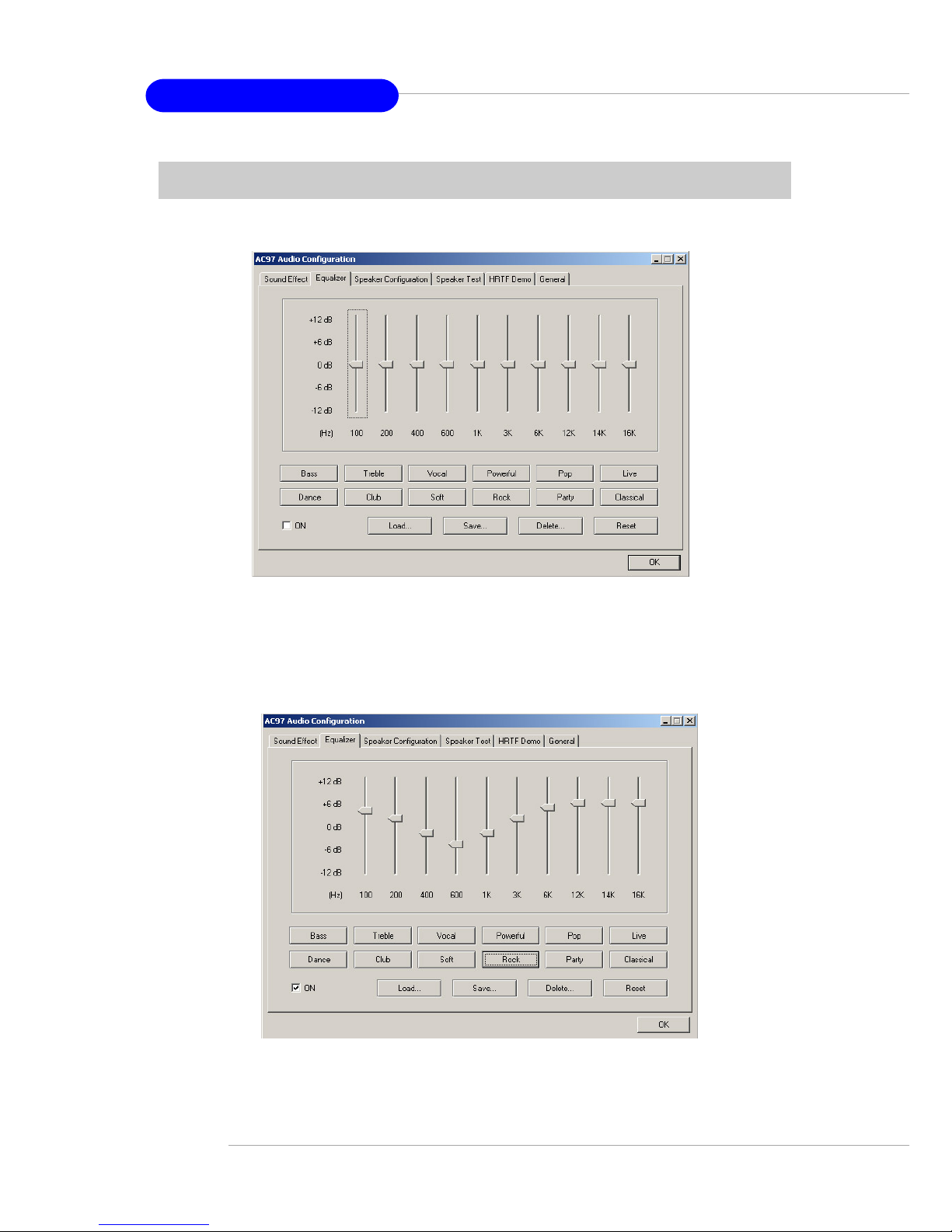
Equalizer
Here you regulate each equalizer for current playing digital sound sources.
You may choose the provided sound effects, and the equalizer will adjust
automatically. If you like, you may also load an equalizer setting or make an
new equalizer setting to save as an new one by using the buttons Load and
Save. Or you may click Reset to use the default value.
Page 66

A-7
Using 4- or 6-Channel Audio Function
Speaker Configuration
In this tab, you can easily configure your multi-channel audio function
and speakers.
1. Select the audio configuration below which is identical to the audio
jack in your mainboard.
2. Select a desired multi-channel operation from Number of Speaker.
a. Headphone for the common headphone
b. 2-Channel Mode for Stereo-Speaker Output
c. 4-Channel Mode for 4-Speaker Output
d. 6-Channel Mode for 5.1-Speaker Output
3. Here it shows the multi-channel setting for the audio jack. Please connect
your speakers to the correct phone jack in accordance with the setting
displayed here.
4. Then click OK to apply the configuration.
2
3
1
Page 67
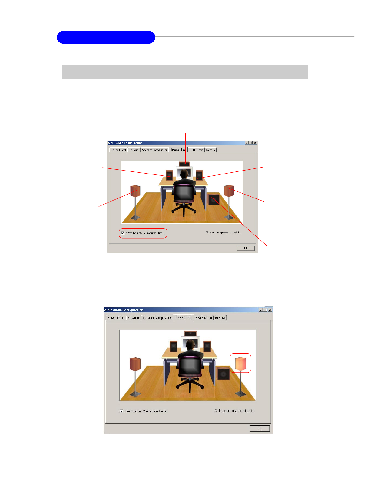
A-8
MS-6799 ATX Mainboard
Speaker Test
You can use this tab to test each connected speaker to ensure if 4- or 6channel audio operation works properly. If any speaker fails to make sound,
then check whether the cable is inserted firmly to the connector or replace the
bad speakers with good ones.
Select the speaker by clicking it to test its functionality. The one you
select will light up and make testing sound.
Select this function
Subwoofer
Front Right
Rear Right
Center
Front Left
Rear Left
Page 68
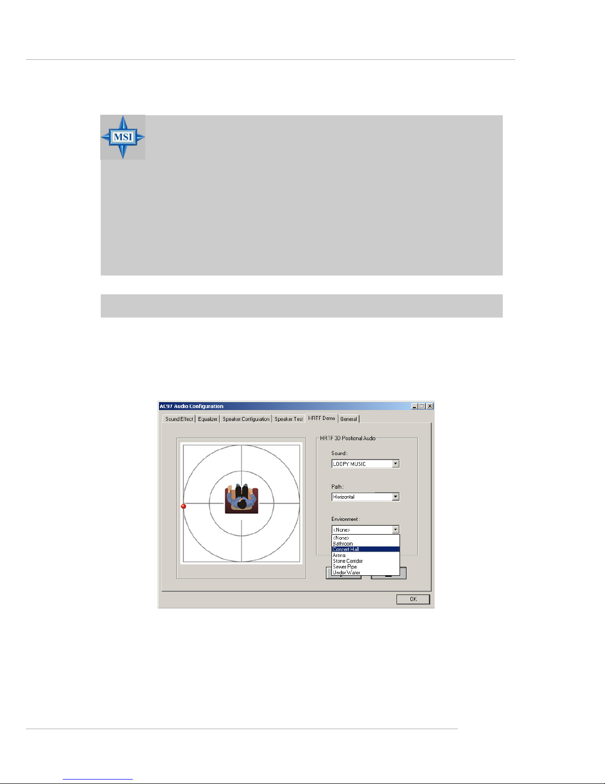
A-9
Using 4- or 6-Channel Audio Function
MSI Reminds Y ou...
1. 6 speakers appear on the “Speaker Test” tab only when you
select “6-Channel Mode” in the “Number of Speakers” col-
umn in “Speaker Configuration” tab. If you select “4-Channel Mode”, only 4 speakers appear on the window.
2. While you are testing the speakers in 6-Channel Mode, if the
sound coming from the center speaker and subwoofer is
swapped, you should select Swap Center/Subwoofer Output
to readjust these two channels.
HRTF Demo
In this tab you may adjust your HR TF (Head Related T ransfer Functions)
3D positional audio before playing 3D audio applications like gaming. Y ou may
also select different environment to choose the most suitable environment you
like.
Page 69
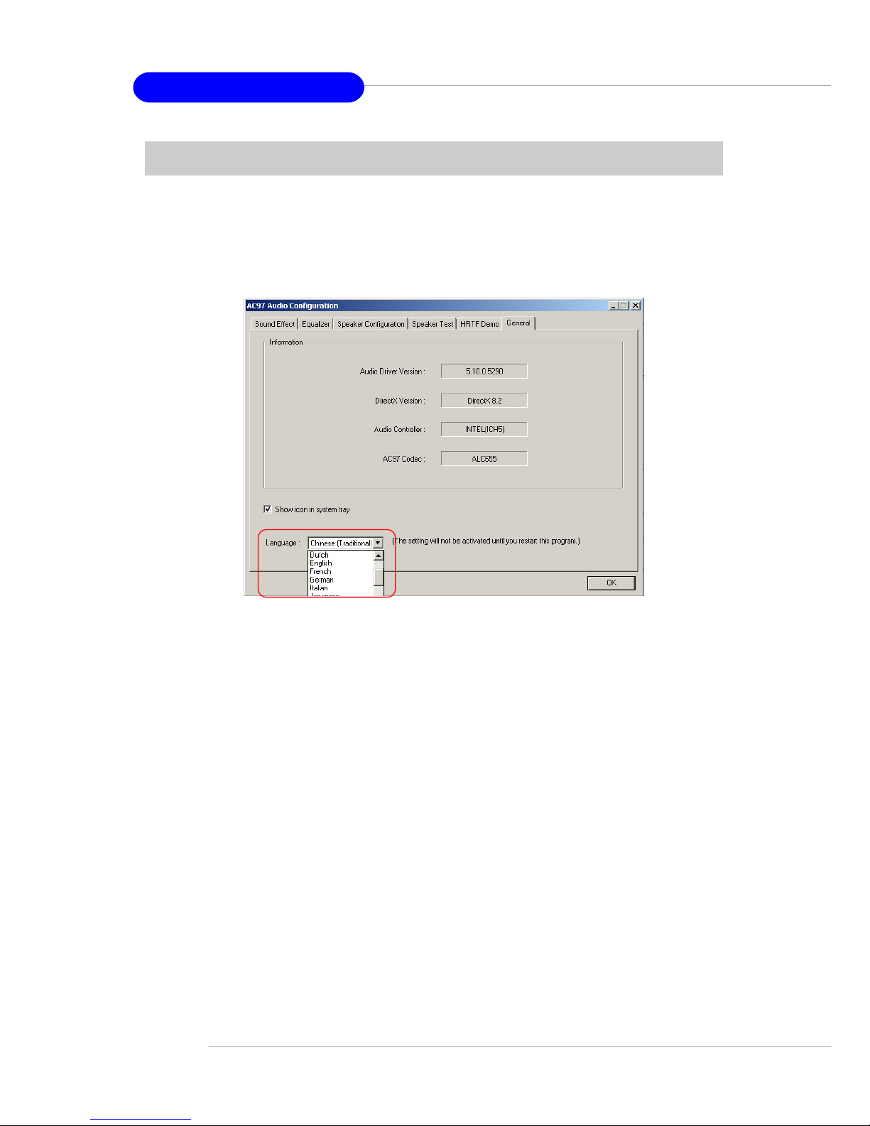
A-10
MS-6799 ATX Mainboard
General
In this tab it provides some information about this AC97 Audio Configu-
ration utility , including Audio Driver Version, DirectX Version, Audio Controller & AC97 Codec. You may also select the language of this utility by choosing
from the Language list.
Page 70
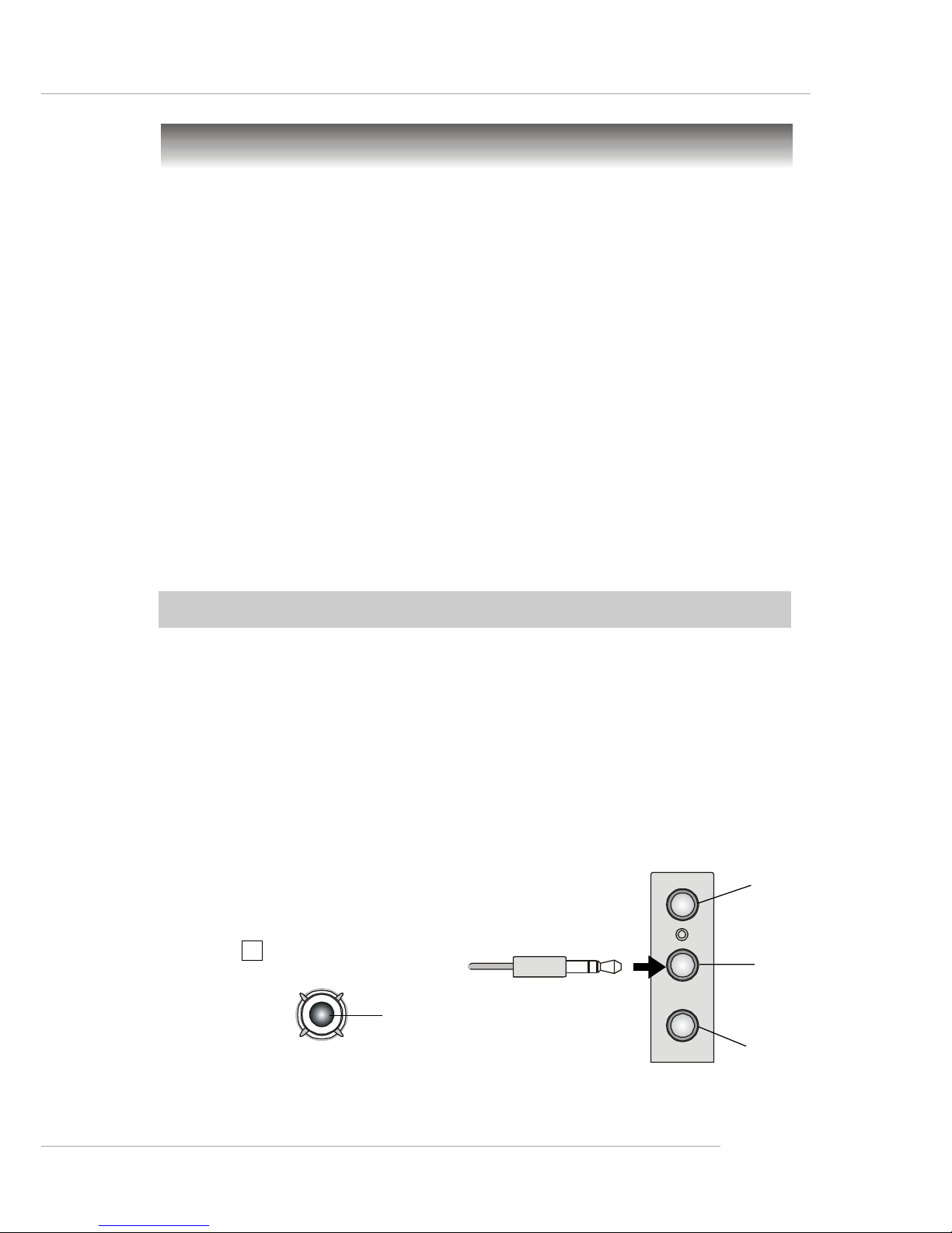
A-11
Using 4- or 6-Channel Audio Function
Using 2-, 4- & 6- Channel Audio Function
After installing the audio driver, you are able to use the 4-/6-channel
audio feature now . T o enable 4- or 6-channel audio operation, first connect 4 or
6 speakers to the appropriate audio connectors, and then select 4- or 6-channel
audio setting in the software utility.
There are two ways to utilize the function and connect the speakers to
your computer:
Using the back panel only
If you do not have a S-Bracket, you can connect all speakers to the
audio connectors on the back panel.
Using the optional S-Bracket
If your motherboard supports S-Bracket and you have installed SBracket in the computer, you can connect two speakers to back
panel’s Line-Out connector , and the rest of speakers to S-Bracket.
Connecting the Speakers
When you have set the Multi-Channel Audio Function mode properly in
the software utility, connect your speakers to the correct phone jacks in
accordance with the setting in software utility.
2-Channel Mode for Stereo-Speaker Output
Refer to the following diagram and caption for the function of each
phone jack on the back panel when 2-Channel Mode is selected.
4
Using the Back Panel only
1 Line In
2 Line Out (Front channels)
3 MIC
4 Coaxial SPDIF jack
Back Panel
3
1
2
Page 71
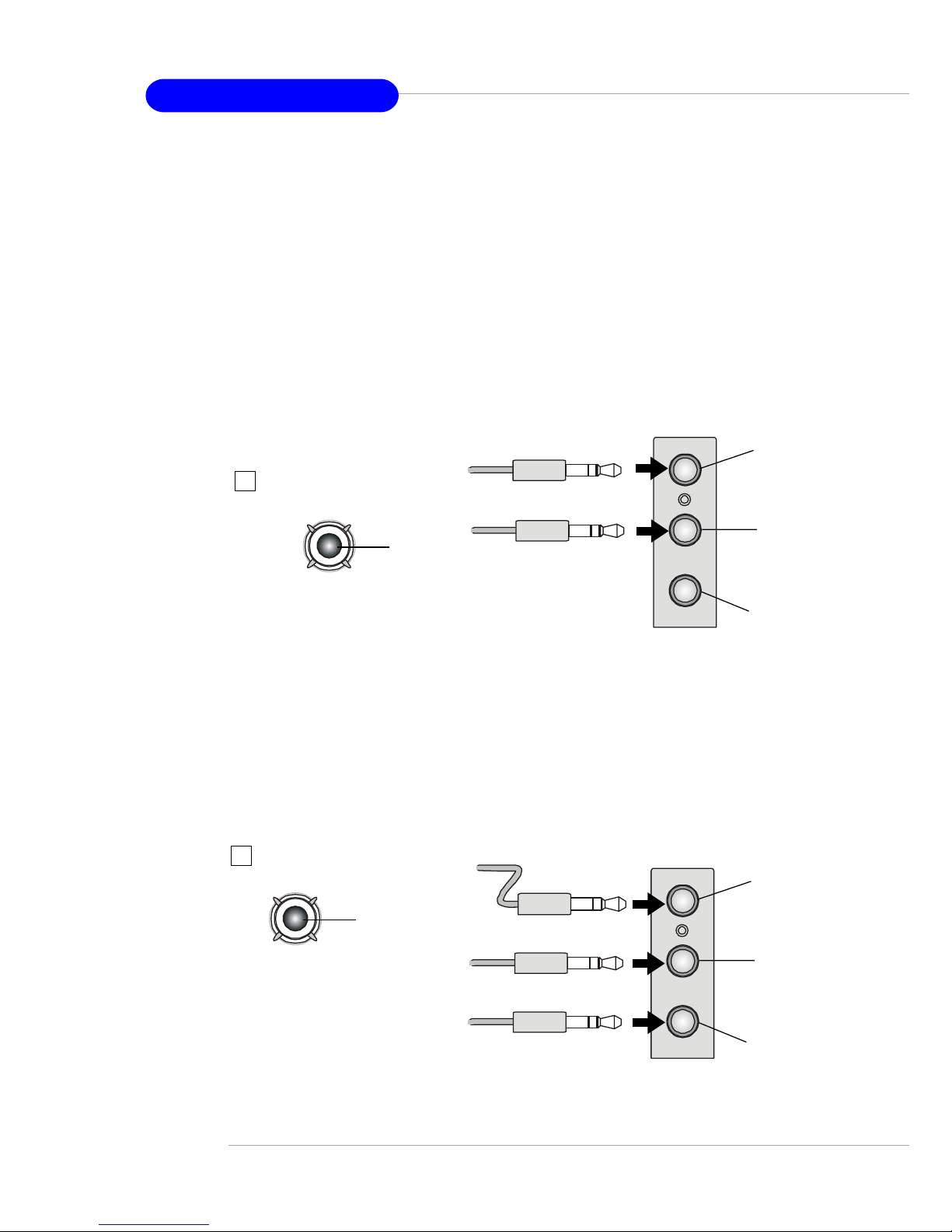
A-12
MS-6799 ATX Mainboard
4-Channel Mode for 4-Speaker Output
The audio jacks on the back panel always provide 2-channel analog
audio output function, however these audio jacks can be transformed
to 4- or 6- channel analog audio jacks by selecting the corresponding
multi-channel operation from No. of Speakers.
Refer to the following diagram and caption for the function of each
jack on the back panel when 4-Channel Mode is selected.
4
Back Panel
3
1
2
1 *Line Out (Rear channels)
2 Line Out (Front channels)
3 MIC
4 Coaxial SPDIF jack
* Line In function is converted to Line Out
function when 4-Channel Mode for 4-Speaker
Output is selected.
* Both Line In and MIC
function are converted to Line
Out function when 6-Channel
Mode for 6-Speaker Output is
selected.
6-Channel Mode for 6-Speaker Output
Refer to the following diagram and caption for the function of each
jack on the back panel when 6-Channel Mode is selected.
1 * Line Out (Rear channels)
2 Line Out (Front channels)
3 * Line Out (Center and Subwoofer channel)
4 Coaxial SPDIF jack
Back Panel
3
1
2
4
Page 72
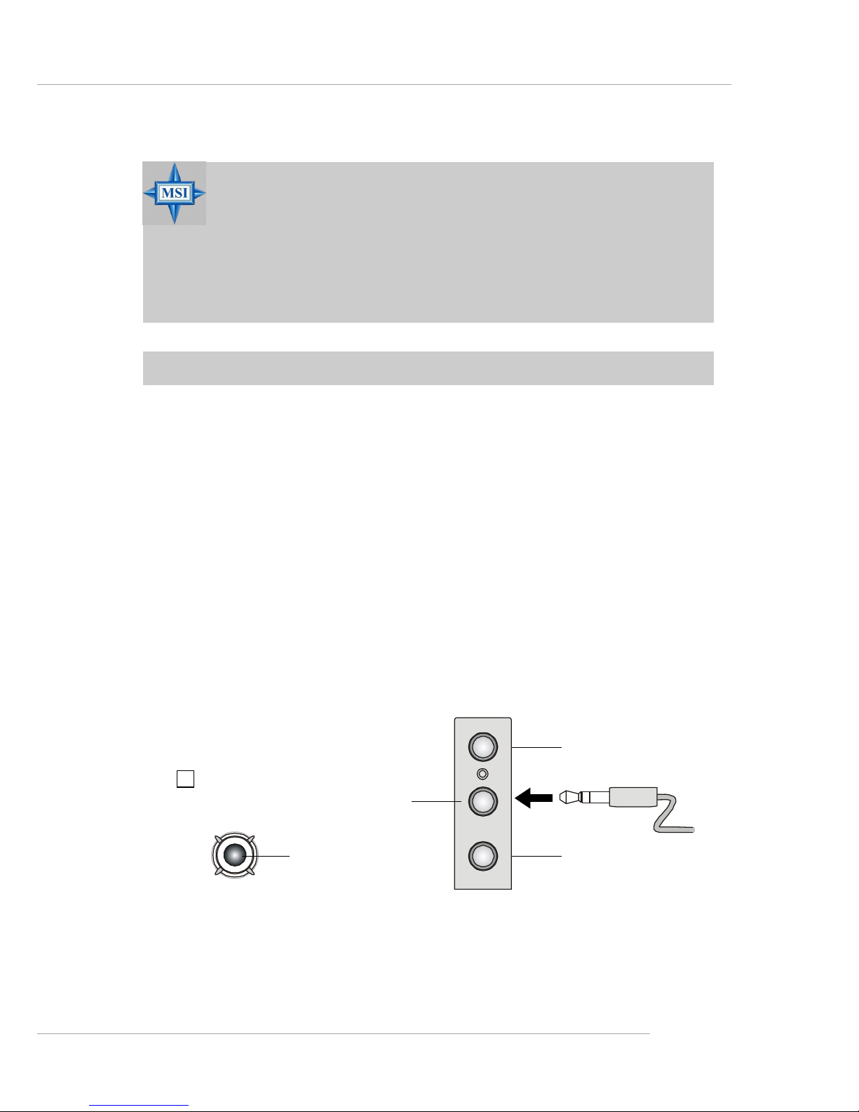
A-13
Using 4- or 6-Channel Audio Function
2-Channel Analog Audio Output
W e recommend that you should still attach the speakers to BACK P ANEL ’ s
Line Out connector during 2-channel audio mode even though S-Bracket’s
Line Out connectors function properly.
MSI Reminds Y ou...
If the audio signals coming from the Center and Subwoofer
speaker are swapped when you play video or music on the
computer, a converter may be required to exchange center and
subwoofer audio signals. The converter can be purchased from
a speaker store.
Using the Optional S-Bracket
S-Bracket is an optional accessory. It gives access to analog and digital
audio output by integrating both SPDIF (Sony & Philips Digital Interface) and
analog LINE OUT connectors. T o use the S-Bracket, you should select correct
setting in the software utility. For information about the setting, refer to Se-
lecting 2-, 4- or 6-Channel Setting later in the section.
Connector configurations for 2-, 4- and 6-channel using S-Bracket are
described below:
4
1 MIC
2 Line Out (Front channels)
3 Line In
4 Coaxial SPDIF jack
Back Panel
1
2
3
Page 73
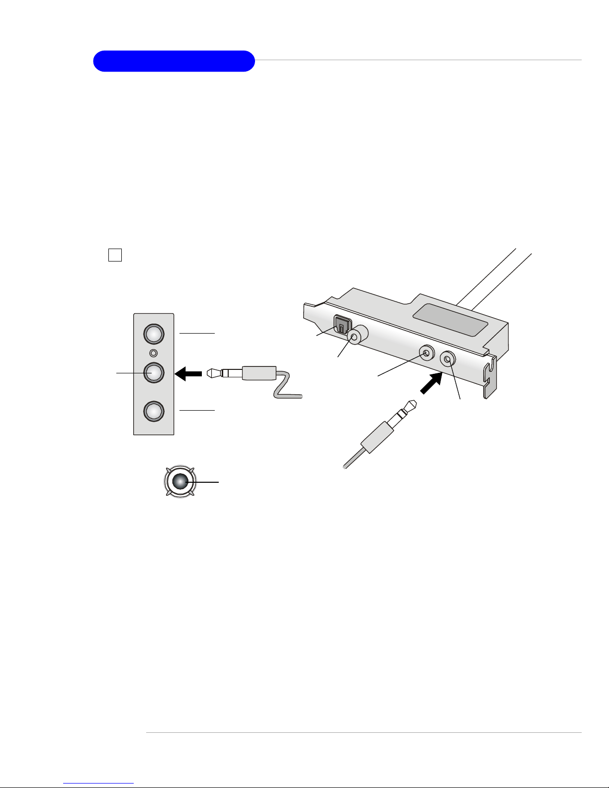
A-14
MS-6799 ATX Mainboard
4-Channel Analog Audio Output
Description:
Connect two speakers to back panel’s Line Out
connector and two speakers to one Line Out
connector of S-Bracket.
1 MIC
2 Line Out (Front channels)
3 Line In
4 Optical SPDIF jack
5 Coaxial SPDIF jack
6 Line Out (Center and Subwoofer channel, but no functioning in this mode)
7 Line Out (Rear channels)
8 Coaxial SPDIF jack
Back Panel
S-Bracket
8
7
2
3
4
5
6
1
Page 74
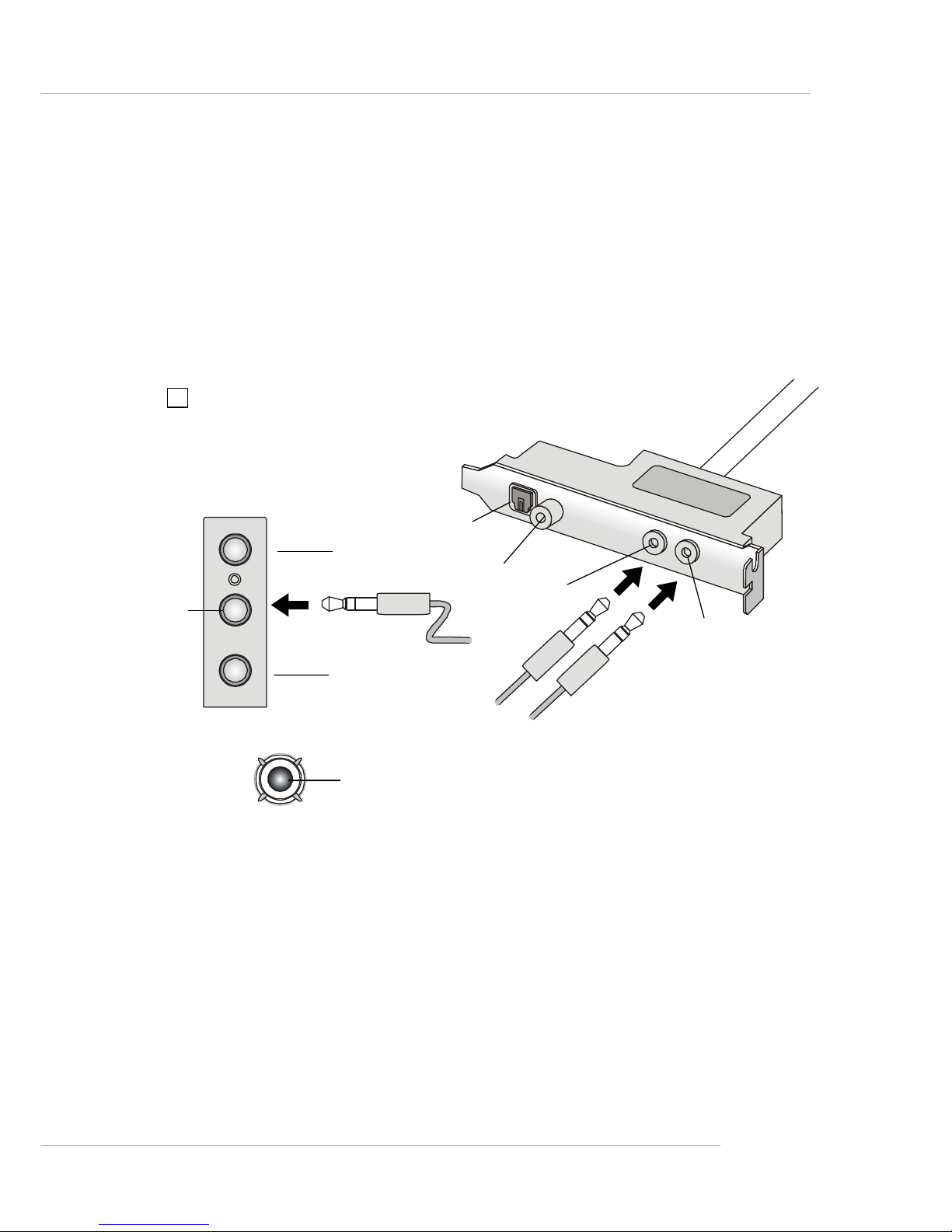
A-15
Using 4- or 6-Channel Audio Function
6-Channel Analog Audio Output
Description:
Connect two speakers to back panel’s Line Out
connector and four speakers to both Line Out
connectors of S-Bracket.
1 MIC
2 Line Out (Front channels)
3 Line In
4 Optical SPDIF jack
5 Coaxial SPDIF jack
6 Line Out (Center and Subwoofer channel)
7 Line Out (Rear channels)
8 Coaxial SPDIF jack
S-Bracket
Back Panel
8
7
2
3
4
5
6
1
Page 75
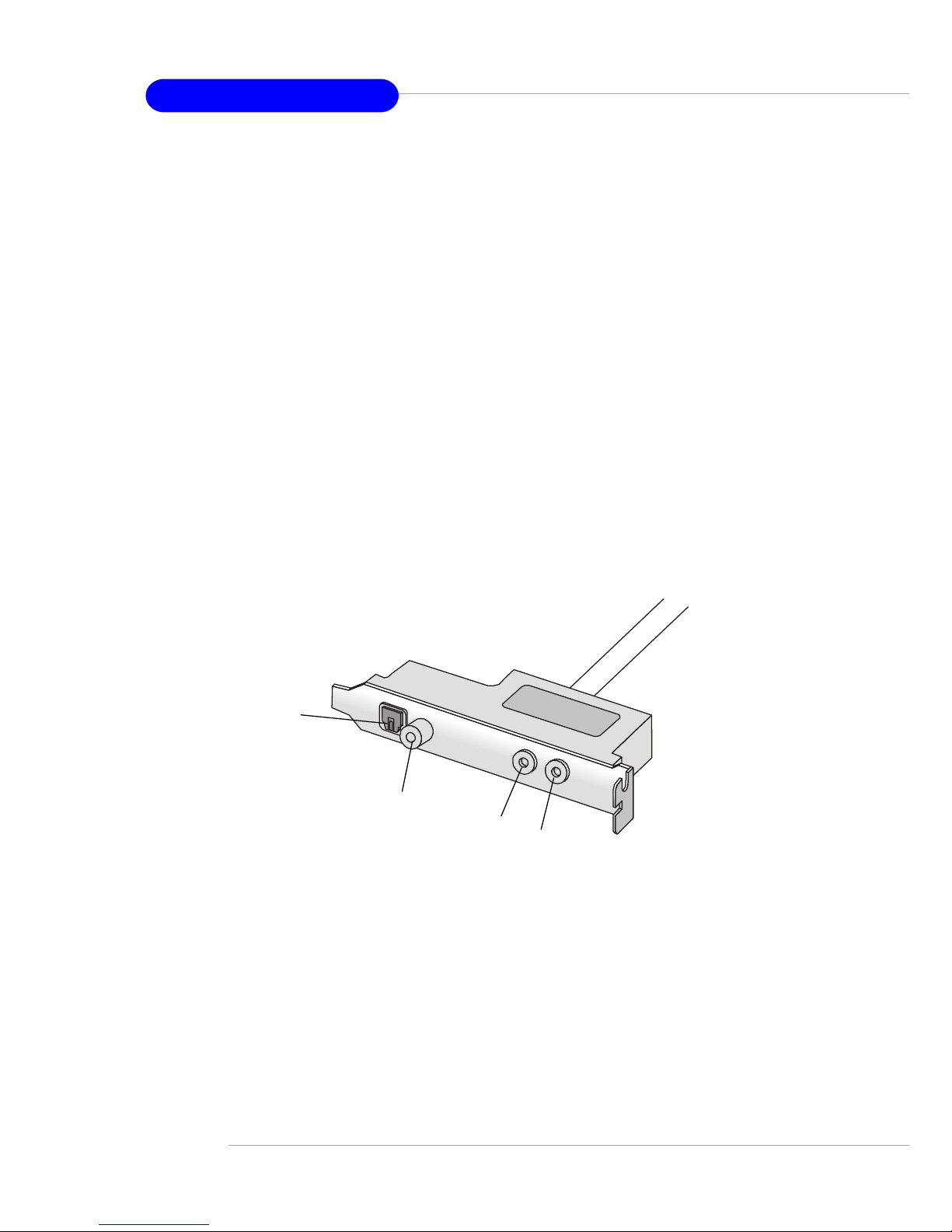
A-16
MS-6799 ATX Mainboard
1 Optical SPDIF jack
2 Coaxial SPDIF jack
3 Line Out
4 Line Out
Description:
Select the correct type of SPDIF jack to connect
SPDIF speakers. For optical connection,
remove the plug from the S-Bracket before
inserting the fiber-optic cable to it.
Digital Audio Output (2-Channel only)
For digital audio output, use the SPDIF (Sony & Philips Digital Interface)
connectors supplied by S-Bracket. First, connect the SPDIF speakers to the
appropriate SPDIF jack, and then select the audio channel you desire through
the control panel of speakers. The SPDIF connectors support 2-channel audio
operation only.
S-Bracket offers two types of SPDIF jacks: one for fiber-optic cable and
the other for coaxial cable. Select the connector according to the type of your
SPDIF speakers.
S-Bracket
2
1
4
3
Page 76

VIA VT8237 Serial ATA RAID Introduction
B-1
Appendix. Using 4- or 6-Channel
Audio Function
Appendix B: VIA VT8237 Serial ATA
RAID Introduction
The Southbridge VT8237 provides a hybrid solution that combines two
independent SATA ports for support of up to two Serial ATA (Serial ATA
RAID) drives.
Serial ATA (SATA) is the latest generation of the AT A interface. SAT A
hard drives deliver blistering transfer speeds of up to 150MB/sec. Serial ATA
uses long, thin cables, making it easier to connect your drive and improving
the airflow inside your PC.
The key features of VT8237 SAT A RAID are:
1. Support two SATA + two PATA hard disk drives.
2. Only SATA supports RAID.
3 . Supports ATA 133 high performance hard disk drive.
4. Dual independent ATA channels and maximum connection of four
hard disk drives allowed.
5 . Supports Ultra DMA mode 6/5/4/3/2/1/0, DMA mode 2/1/0, and PIO
mode 4/3/2/1/0.
6 . Supports RAID 0 and RAID 1.
7 . 4 KB to 64 KB striping block size support.
8. Bootable disk or disk array support.
9. Windows-based RAID configure and management software tool.
(Compatible with BIOS)
1 0. Supports hot-swap failed disk drive in RAID 1 array.
11. ATA SMART function support.
12. Microsoft Windows 98, Me, NT4.0, 2000, XP operating systems
support.
13. Event log for easy troubleshooting.
Page 77
MS-6799 ATX Mainboard
B-2
Introduction
This section gives a brief introduction on the RAID-related background
knowledge and a brief introduction on VIA SAT A RAID Host Controller. For
users wishing to install their VIA SATA RAID driver and RAID software,
proceed to Driver and RAID Software Installation section.
RAID Basics
RAID (Redundant Array of Independent Disks) is a method of combining
two or more hard disk drives into one logical unit. The advantage of an Array
is to provide better performance or data fault tolerance. Fault tolerance is
achieved through data redundant operation, where if one drives fails, a mirrored
copy of the data can be found on another drive. This can prevent data loss if
the operating system fails or hangs. The individual disk drives in an array are
called “members”. The configuration information of each member is recorded
in the “reserved sector” that identifies the drive as a member. All disk members
in a formed disk array are recognized as a single physical drive to the operating
system.
Hard disk drives can be combined together through a few different
methods. The different methods are referred to as different RAID levels.
Different RAID levels represent different performance levels, security levels
and implementation costs. The RAID levels which the VIA VT8237 SATA
RAID Host Controller supports are RAID 0 and RAID 1. The table below
briefly introduced these RAID levels.
RAID Level No. of Drives Capacity Benefits
RAID 0
(Striping)
2 Number drives * 2 Highest performance without data
protection
RAID 1
(Mirroring)
2 Smallest size Data protection
Page 78

VIA VT8237 Serial ATA RAID Introduction
B-3
RAID 0 (Striping)
RAID 0 reads and writes sectors of data interleaved between multiple
drives. If any disk member fails, it affects the entire array. The disk array data
capacity is equal to the number of drive members times the capacity of the
smallest member. The striping block size can be set from 4KB to 64KB. RAID
0 does not support fault tolerance.
RAID 1 (Mirroring)
RAID 1 writes duplicate data onto a pair of drives and reads both sets of
data in parallel. If one of the mirrored drives suffers a mechanical failure or
does not respond, the remaining drive will continue to function. Due to
redundancy, the drive capacity of the array is the capacity of the smallest
drive. Under a RAID 1 setup, an extra drive called the .spare drive. can be
attached. Such a drive will be activated to replace a failed drive that is part of
a mirrored array. Due to the fault tolerance, if any RAID 1 drive fails, data
access will not be affected as long as there are other working drives in the
array.
Page 79
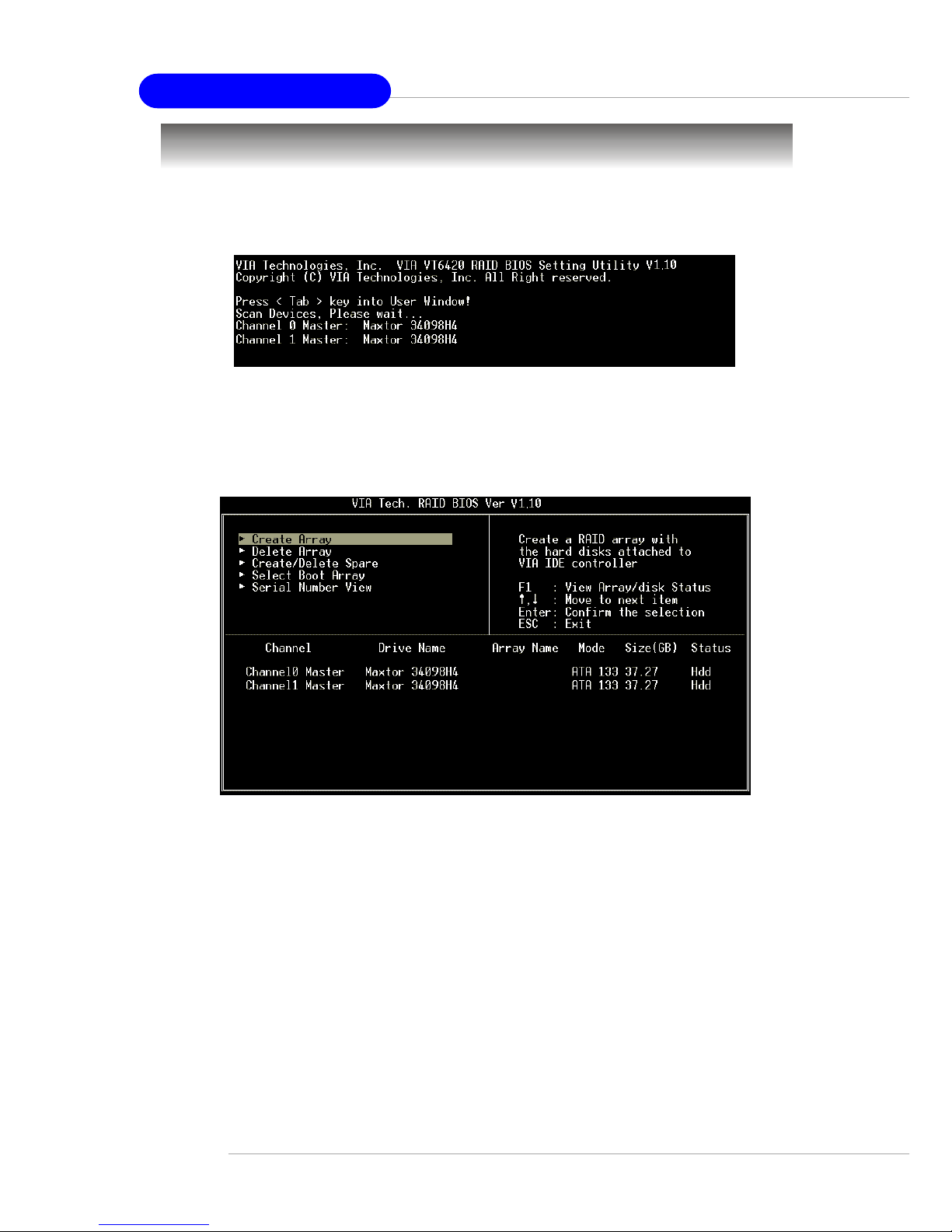
MS-6799 ATX Mainboard
B-4
BIOS Configuration
When the system powers on during the POST (Power-On Self Test)
process, press <Tab> key to enter the BIOS configuration.
The Serial ATA RAID volume may be configured using the VIA Tech.
RAID BIOS. Always use the arrow keys to navigate the main menu, use up and
down arrow key to select the each item and press <Enter> to call out the list of
creation steps. The main interface of BIOS configuration utility is as below:
Page 80
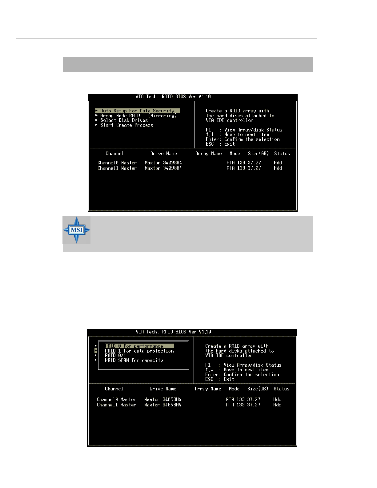
VIA VT8237 Serial ATA RAID Introduction
B-5
Create Disk Array
Use the up and down arrow keys to select the Create Array command
and press <Enter>.
MSI Reminds Y ou...
The “Channel”, “Drive Name”, “Mode” and “Size (GB)” in the
following example might be different from your system.
Select Array Mode and press <Enter>, a list of array modes will appear.
Highlight the target array mode that you want to create, and press <Enter> to
confirm the selection. If RAID 1 or RAID 0/1 is selected, an option list will
popup and enable the users to select Create only or Create and duplicate.
Create only will allow BIOS to only create an array. The data on the mirroring
drive may be different from the source drive. Create and duplicate lets BIOS
copy the data from the source to the mirroring drive.
Page 81
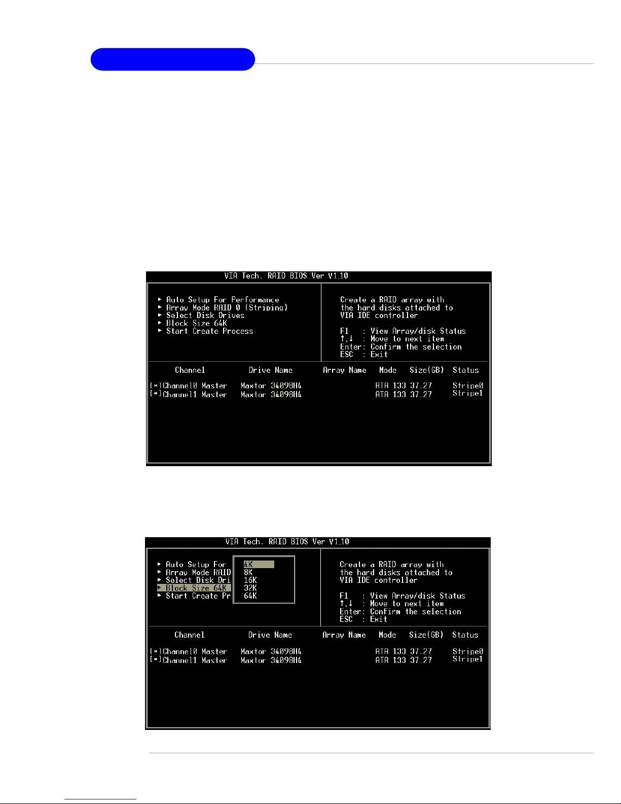
MS-6799 ATX Mainboard
B-6
If user selects a RAID 0 array in step 2, the block size of the array can also
be selected. Use the arrow key to highlight Block Size and press <Enter>,
then select a block size from the popup menu. The block size can be 4KB to
64KB.
After array mode is selected, there are two methods to create a disk
array. One method is “Auto Setup” and the other one is “Select Disk Drives”.
Auto Setup allows BIOS to select the disk drives and create arrays automatically,
but it does not duplicate the mirroring drives even if the user selected Create
and duplicate for RAID 1. It is recommended all disk drives are new ones when
wanting to create an array. Select Disk Drives lets the user select the array
drives by their requirements. When using Select Disk Drives, the channel
column will be activated. Highlight the target drives that you want to use and
press <Enter> to select them. After all drives have been selected, press <Esc>
to go back to the creation steps menu.
Page 82

VIA VT8237 Serial ATA RAID Introduction
B-7
Use the arrow key to highlight Start Create Process and press <Enter>.
A warning message will appear, Press Y to finish the creation, or press N to
cancel the creation.
Important note: All existing content in the hard drive will be destroyed
after array creation.
MSI Reminds Y ou...
Even though 64KB is the recommended setting for most users, you
should choose the block size value which is best suited to your
specific RAID usage model.
4KB: For specialized usage models requiring 4KB blocks
8KB: For specialized usage models requiring 8KB blocks
16KB: Best for sequential transfers
32KB: Good for sequential transfers
64KB: Optimal setting
Page 83
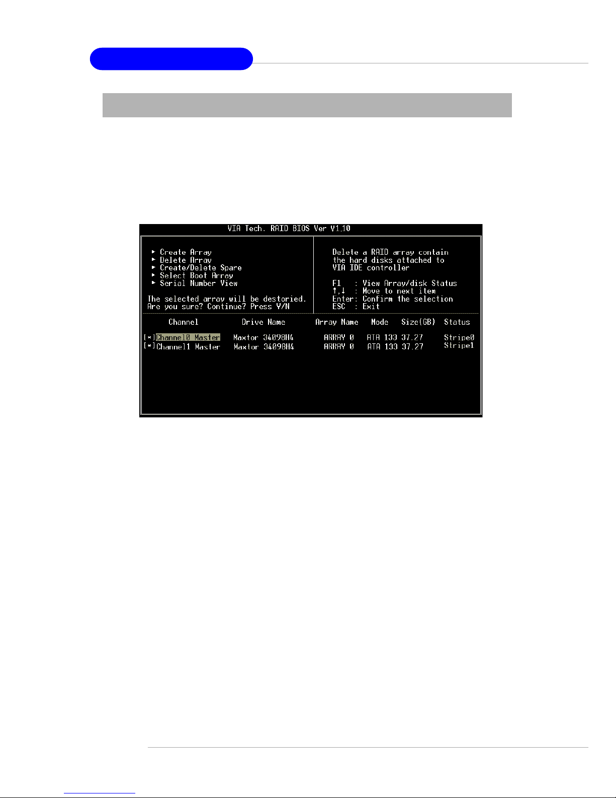
MS-6799 ATX Mainboard
B-8
Delete Disk Array
A RAID can be deleted after it has been created. T o delete a RAID, use
the following steps:
1. Select Delete Array in the main menu and press <Enter>. The channel
column will be activated.
2 . Select the member of an array that is to be deleted and press <Enter>. A
warning message will show up, press Y to delete or press N to cancel.
Deleting a disk array will destroy all the data on the disk array except
RAID 1 arrays. When a RAID is deleted, the data on these two hard disk drives
will be reserved and become two normal disk drives.
Page 84
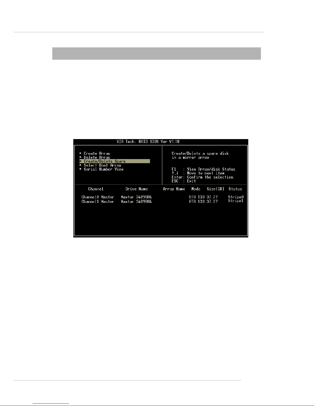
VIA VT8237 Serial ATA RAID Introduction
B-9
Create and Delete Spare Hard Drive
If a RAID 1 array is created and there are drives that do not belong to
other arrays, the one that has a capacity which is equal to or greater than the
array capacity can be selected as a spare drive for the RAID 1 array. Select
Create/Delete Spare and press <Enter>, the channel column will then be
activated. Select the drive that you want to use as a spare drive and press
<Enter>, the selected drive will be marked as Spare. The spare drive cannot be
accessed in an OS.
T o delete a spare drive, highlight Create/Delete Spare and press <Enter>.
The spare drive will be highlighted, press <Enter> to delete the spare drive.
Page 85
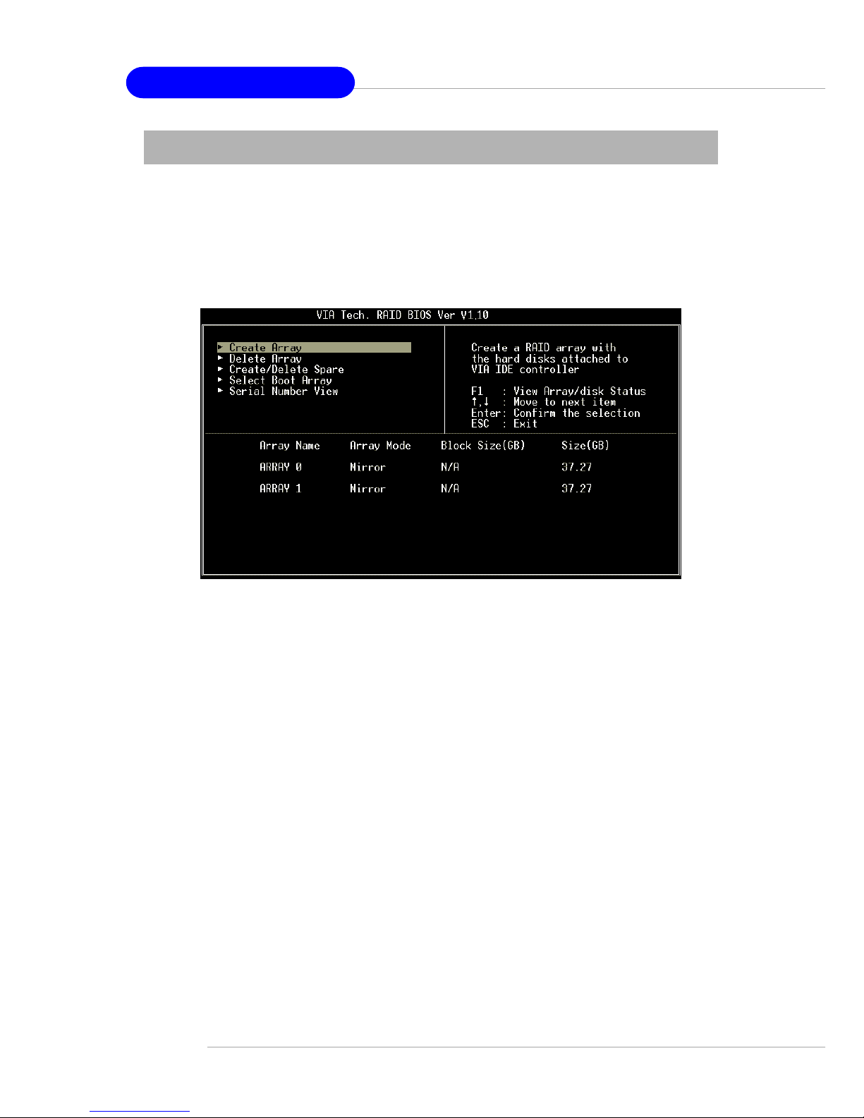
MS-6799 ATX Mainboard
B-10
View Serial Number of Hard Drive
Highlight Serial Number View and press <Enter>. Use arrow key to
select a drive, the selected drive’s serial number can be viewed in the last
column. The serial number is assigned by the disk drive manufacturer.
Press the F1 key to show the array status on the lower screen. If there are
no disk arrays then nothing will be displayed on the screen.
Page 86
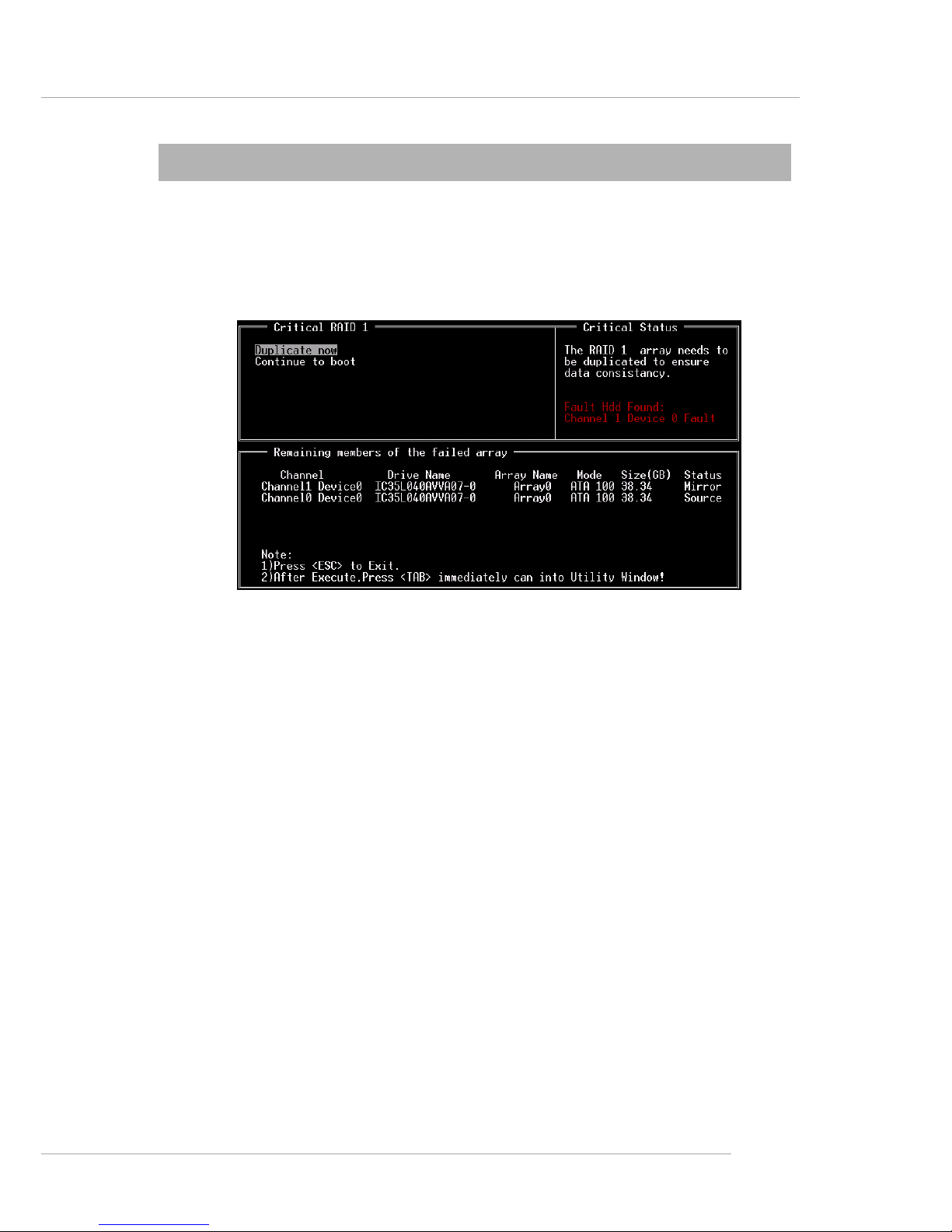
VIA VT8237 Serial ATA RAID Introduction
B-11
Duplicate Critical RAID 1 Array
When booting up the system, BIOS will detect if the RAID 1 array has
any inconsistencies between user data and backup data. If BIOS detects any
inconsistencies, the status of the disk array will be marked as critical, and BIOS
will prompt the user to duplicate the RAID 1 in order to ensure the backup data
consistency with the user data.
If user selects Continue to boot, it will enable duplicating the array after
booting into OS.
Page 87
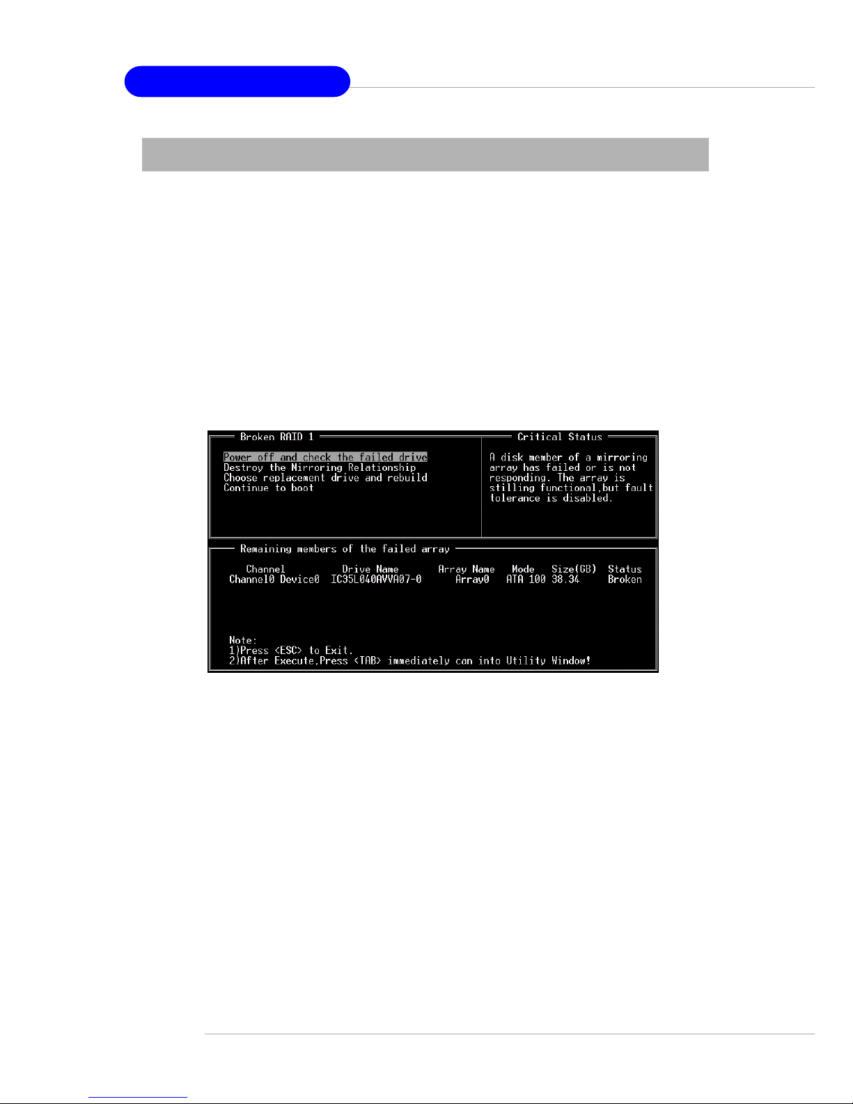
MS-6799 ATX Mainboard
B-12
Rebuild Broken RAID 1 Array
When booting up the system, BIOS will detect if any member disk drives
of RAID has failed or is absent. If BIOS detects any disk drive failures or
missing disk drives, the status of the array will be marked as broken.
If BIOS detects a broken RAID 1 array but there is a spare hard drive
available for rebuilding the broken array, the spare hard drive will automatically
become the mirroring drive. BIOS will show a main interface just like a duplicated
RAID 1. Selecting Continue to boot enables the user to duplicate the array after
booting into operating system.
If BIOS detects a broken RAID 1 array but there is no spare hard drive
available for rebuilding the array, BIOS will provide several operations to
solve such problem.
1. Power off and Check the Failed Drive:
This item turns off the computer and replaces the failed hard drive with a
good one. If your computer does not support APM, you must turn off your
computer manually. After replacing the hard drive, boot into BIOS and select
Choose replacement drive and rebuild to rebuild the broken array.
2. Destroy the Mirroring Relationship:
This item cancels the data mirroring relationship of the broken array. For
broken RAID 1 arrays, the data on the surviving disk will remain after the
destroy operation. However, Destroy the Mirroring Relationship is not
recommend because the data on the remaining disk will be lost when the hard
drive is used to create another RAID 1 array.
Page 88
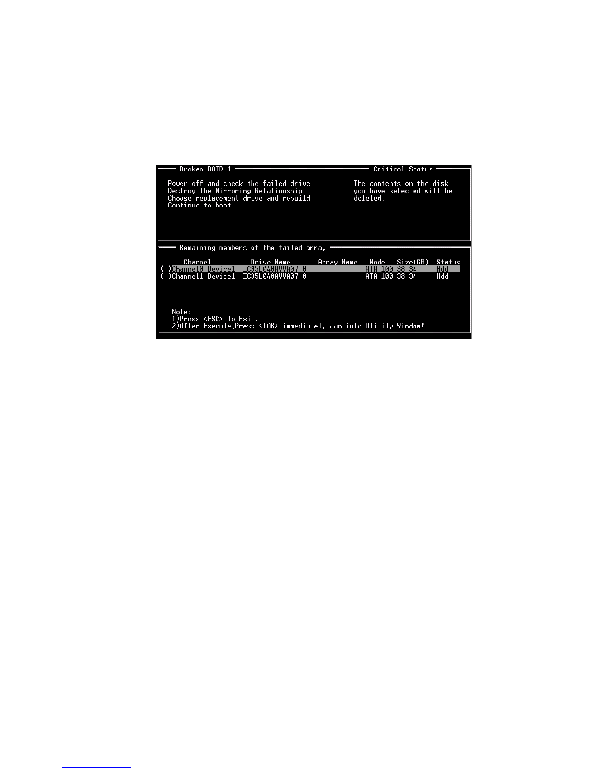
VIA VT8237 Serial ATA RAID Introduction
B-13
3. Choose Replacement Drive and Rebuild:
This item enables users to select an already-connected hard drive to
rebuild the broken array. After choosing a hard drive, the channel column will
be activated.
Highlight the target hard drive and press <Enter>, a warning message
will appear. Press Y to use that hard drive to rebuild, or press N to cancel.
Please note selecting option Y will destroy all the data on the selected hard
drive.
4. Continue to boot:
This item enables BIOS to skip the problem and continue booting into
OS.
Page 89

MS-6799 ATX Mainboard
B-14
Install Driver in Windows OS
h New Windows OS (2000/XP/NT4) Installation
The following details the installation of the drivers while installing Windows
XP.
1. Start the installation:
Boot from the CD-ROM. Press F6 when the message "Press F6 if you
need to install third party SCSI or RAID driver" appears.
2. When the Windows Setup window is generated, press S to
specify an Additional Device(s).
3. Insert the driver diskette VIA VT6420/VT8237 Disk Driver into
drive A: and press <Enter>.
4. Depending on your operation system, choose VIA Serial ATA RAID
Controller(Windows XP), VIA Serial ATA RAID Controller(Windows 2000)
or VIA Serial A TA RAID Controller(Windows NT4) from the list that appears
on Windows XP Setup screen, press the <Enter> key.
5. Press <Enter> to continue with installation or if you need to specify
any additional devices to be installed, do so at this time. Once all devices are
specified, press <Enter> to continue with installation.
6. From the Windows XP Setup screen, press the <Enter> key. Setup
will now load all device files and then continue the Windows XP installation
h Existing Windows XP Driver Installation
1. Insert the MSI CD into the CD-ROM drive.
2. The CD will auto-run and the setup screen will appear.
3. Under the Driver tab, click on VIA SA TA RAID Utility.
4. The drivers will be automatically installed.
h Confirming Windows XP Driver Installation
1. From Windows XP, open the Control Panel from My Computer
followed by the System icon.
2. Choose the Hardware tab, then click the Device Manager tab.
3. Click the "+" in front of the SCSI and RAID Controllers hardware
type. The driver VIA IDE RAID Host Controller should appear.
Installing RAID Software & Drivers
Page 90
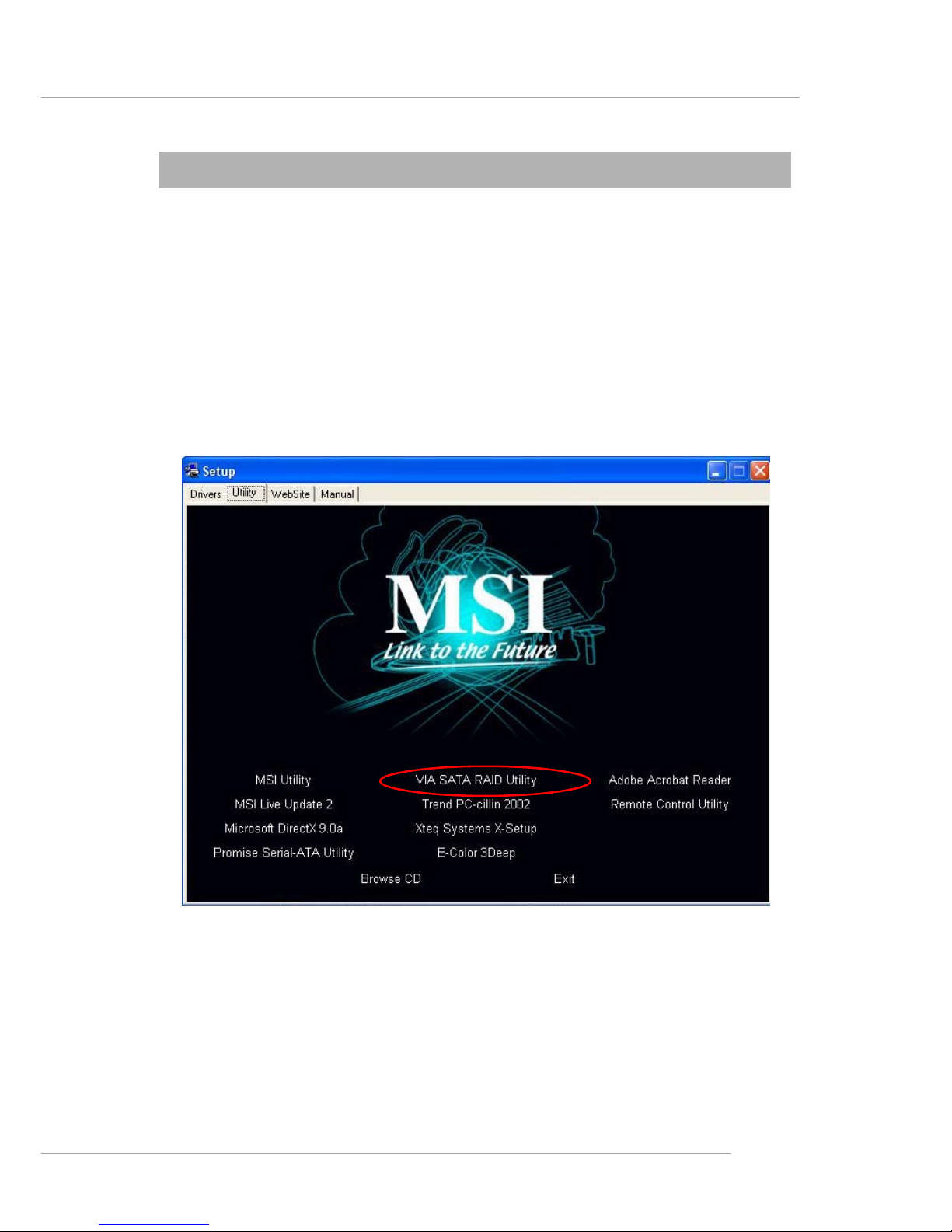
VIA VT8237 Serial ATA RAID Introduction
B-15
Installation of VIA SA TA RAID Utility
The VIA SATA RAID Utility is the software package that enables highperformance RAID 0 arrays in the Windows* XP operating system. This version
of VIA SAT A RAID Utility contains the following key features:
h Serial ATA RAID driver for Windows XP
h VIA SATA RAID utility
h RAID0 and RAID1 functions
Insert the MSI CD and click on the VIA SA T A RAID Utility to install the
software.
Page 91
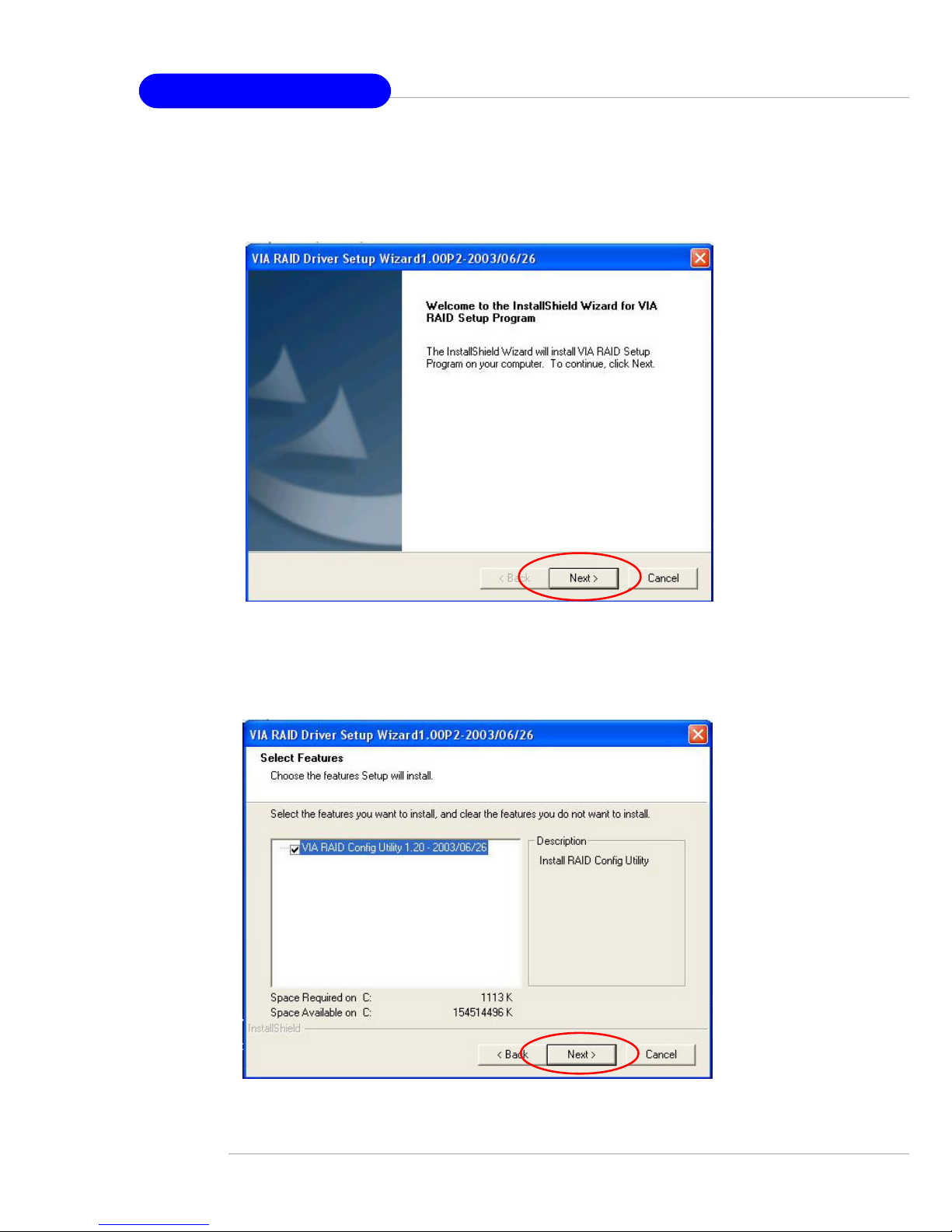
MS-6799 ATX Mainboard
B-16
The InstallShield Wizard will begin automatically for installation. Click on
the Next button to proceed the installation in the welcoming window.
Put a check mark in the check box to install the feature you want. Then click
Next button to proceed the installation.
Page 92
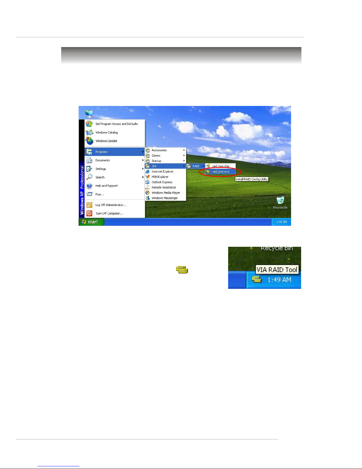
VIA VT8237 Serial ATA RAID Introduction
B-17
Once the installation is complete, go to Start ---> Programs --->VIA --
->raid_tool.exe to enable VIA RAID Tool.
After the software is finished installation, it
will automatically started every time Windows is
initiated. Y ou may double-click on the icon shown
in the system tray of the tool bar to launch the VIA
RAID T ool utility .
Using VIA RAID Tool
Page 93
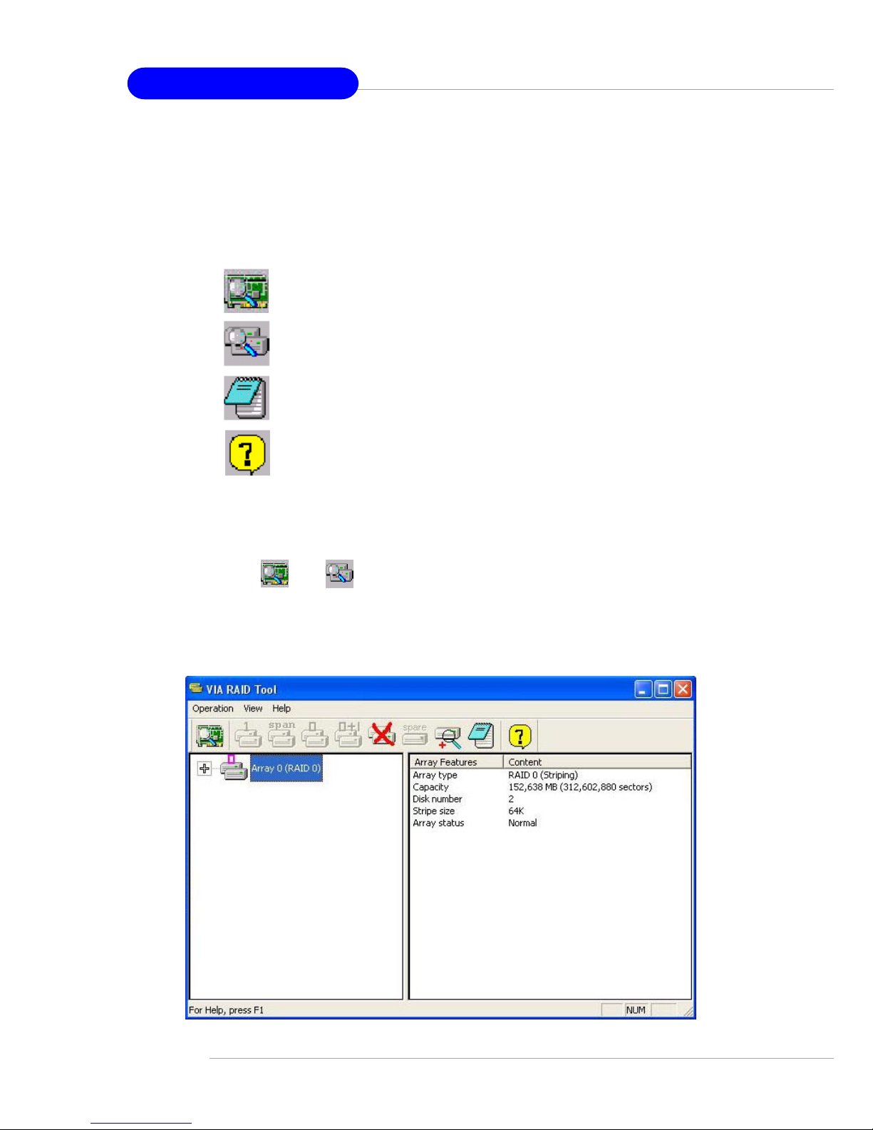
MS-6799 ATX Mainboard
B-18
The main interface is divided into two windows and the toolbar above
contain the main functions. Click on these toolbar buttons to execute their
specific functions. The left windowpane displays the controller and disk drives
and the right windowpane displays the details of the controller or disk drives.
In KT6 Delta, the available features are as following:
Click on o r button to determine the viewing type of left window pane. There are two viewing types: By controllers and by device. Click on
the object in the left window pane to display the status of the object in the right
windowpane. The following screen shows the status of Array 0---RAID 0.
V iew by Controller
V iew Event log
V iew by Devices
Help Topics
It means that VT8237 SAT A RAID in KT6 Delta only has the feature of
monitoring the statuses of RAID 0 and RAID 1.
Page 94
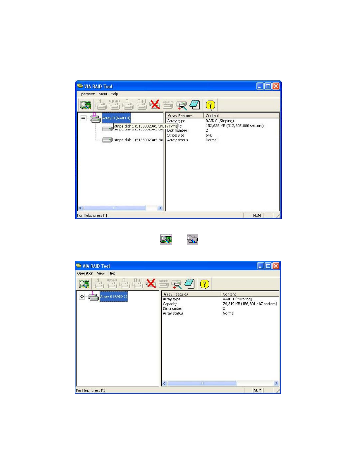
VIA VT8237 Serial ATA RAID Introduction
B-19
Click on the plus (+) symbol next to Array 0---RAID 0 to see the details of
each disk.
You may also use the same o r button to view the statuses of
Array 0---RAID 1.
Page 95
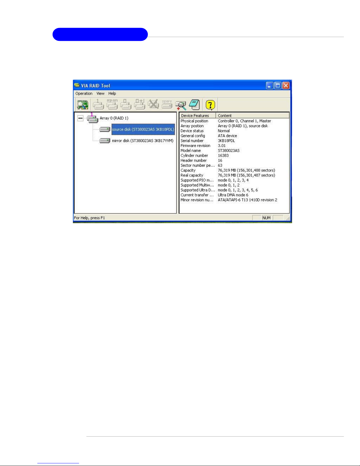
MS-6799 ATX Mainboard
B-20
Click on the plus (+) symbol next to Array 0---RAID 1 to see the details of
each disk.
 Loading...