

Page 1

G52-66371X1
Wind Top AE2200
All-In-One (AIO) PC
MS-6637 (V1.X) System
Page 2
Preface
ii
Upgrade and Warranty
Please be noticed that the memory, hard disk drive and optical disk drive preinstalled
in the product users purchased may be upgradable or replaceable by user’s request.
To learn more about upgrade limitation, please refer to the specication in the User’s
Manual. For any further information about the product users purchased, please contact
the local dealer. Do not attempt to upgrade or replace any component of the product,
if you are not an authorized dealer or service center, since it may cause the warranty
void. It is strongly recommended to contact the authorized dealer or service center for
any upgrade or replace service.
Acquisition of Replaceable Parts
Please be noticed that the acquisition of replaceable parts (or compatible ones) of the
product users purchased in the USA may be fullled by the manufacturer within 5 years
since the product has been discontinued.
■ Please contact the manufacturer via http://www.msicomputer.com/msi_user/msi_
rma/ for the detailed information about the acquisition of spare parts.
Technical Support
If a problem arises with your system and no solution can be obtained from the user’s
manual, please contact your place of purchase or local distributor. Alternatively, please
try the following help resources for further guidance.
■ Visit the MSI website for FAQ, technical guide, BIOS updates, driver updates and other
information via http://www.msi.com/index.php?func=service
■ Contact our technical staff via http://ocss.msi.com/
Copyright Notice
The material in this document is the intellectual property of MICRO-STAR INTERNATIONAL. We take every care in the preparation of this document, but no guarantee is
given as to the correctness of its contents. Our products are under continual improvement
and we reserve the right to make changes without notice.
Trademarks
All trademarks are the properties of their respective owners.
MSI® is a registered trademark of Micro-Star Int’l Co., Ltd.
AMD® is a registered trademark of Advanced Micro Devices, Inc.
AMI® is a registered trademark of American Megatrends, Inc.
ATI® is a registered trademark of ATI Technologies, Inc.
Award® is a registered trademark of Phoenix Technologies Ltd.
Intel® is a registered trademark of Intel Corporation.
JMicron® is a registered trademark of JMicron Technology Corporation.
Netware® is a registered trademark of Novell, Inc.
NVIDIA® is a registered trademark of NVIDIA Corporation.
Realtek® is a registered trademark of Realtek Semiconductor Corporation.
Sound Blaster® is a registered trademark of Creative Technology Ltd.
Windows® is a registered trademark of Microsoft Corporation.
U.S. Patent Numbers
4,631,603; 4,819,098; 4,907,093; 5,315,448; and 6,516,132.
This product incorporates copyright protection technology that is protected by U.S. patents
and other intellectual property rights. Use of this copyright protection technology must
be authorized by Macrovision, and is intended for home and other limited viewing uses
only unless otherwise authorized by Macrovision. Reverse engineering or disassembly
is prohibited.
Revision History
Revision Revision History Date
V1.0 First Release June 2009
Page 3

MS-6637
iii
Upgrade and Warranty
Please be noticed that the memory, hard disk drive and optical disk drive preinstalled
in the product users purchased may be upgradable or replaceable by user’s request.
To learn more about upgrade limitation, please refer to the specication in the User’s
Manual. For any further information about the product users purchased, please contact
the local dealer. Do not attempt to upgrade or replace any component of the product,
if you are not an authorized dealer or service center, since it may cause the warranty
void. It is strongly recommended to contact the authorized dealer or service center for
any upgrade or replace service.
Acquisition of Replaceable Parts
Please be noticed that the acquisition of replaceable parts (or compatible ones) of the
product users purchased in the USA may be fullled by the manufacturer within 5 years
since the product has been discontinued.
■ Please contact the manufacturer via http://www.msicomputer.com/msi_user/msi_
rma/ for the detailed information about the acquisition of spare parts.
Technical Support
If a problem arises with your system and no solution can be obtained from the user’s
manual, please contact your place of purchase or local distributor. Alternatively, please
try the following help resources for further guidance.
■ Visit the MSI website for FAQ, technical guide, BIOS updates, driver updates and other
information via http://www.msi.com/index.php?func=service
■ Contact our technical staff via http://ocss.msi.com/
Page 4
Preface
iv
Safety Instructions
1. Always read the safety instructions carefully.
2. Keep this user’s manual for future reference.
3. Keep this equipment away from humidity.
4. Lay this equipment on a at and steady surface before setting it up.
5. The ventilator on the enclosure is used for air convection and to prevent the
equipment from overheating. Do not cover the ventilator.
6. Check the AC input: 100-240V~, 50-60Hz, 4A.
7. Make sure that the power voltage is within its safety range and has been ad-
justed properly to the value of 100~240V before connecting the equipment
to the power inlet.
8. Place the power cord in a way that people are unlikely to step on it. Do not
place anything on the power cord.
9. Always unplug the power cord before inserting any add-on card or module.
10. All cautions and warnings on the equipment should be noted.
11. Never pour any liquid into the opening that could damage or cause electrical
shock.
12. If any of the following situations arises, get the equipment checked by ser-
vice personnel:
■ The power cord or plug is damaged.
■ Liquid has penetrated into the equipment.
■ The equipment has been exposed to moisture.
■ The equipment does not work well or you can not get it work according to
user’s manual.
■ The equipment has dropped and damaged.
■ The equipment has obvious sign of breakage.
13. DO NOT LEAVE THIS EQUIPMENT IN AN ENVIRONMENT UNCONDI TIONED, STORAGE TEMPERATURE ABOVE 40
o
C (102oF), IT MAY DAM-
AGE THE EQUIPMENT.
WARNING:
1. For every changes in power cord’s usage, please use an approved power
cord with condition greater or equal to H05VV-F, 3G, 0.75mm2.
2. Internal part is hazardous moving parts, please keep ngers and other body
parts away.
3. For pluggable equipment, the socket-outlet shall be installed near the equip
ment and shall be easily accessible.
4. Do not disable the protective earth pin from the plug, the equipment must be
connected to an earthed mains socket-outlet.
5. Adjustment of the volume control as well as the equalizer to other settings
than the center position may increase the ear-/ headphones output voltage
and therefore the sound pressure level.
CAUTION:
Danger of explosion if battery is incorrectly replaced. Replace only with the same or
equivalent type recommended by the manufacturer.
1. The optical storage devices are classied as a Class 1 Laser prod ucts. Use of controls or adjustments or performance of procedures
other than those specied is prohibited.
2. Do not touch the lens inside the drive.
廢電池請回收
For better environmental protection, waste batteries should be collected
separately for recycling or special disposal.
FCC-B Radio Frequency Interference Statement
This equipment has been tested
and found to comply with the limits
for a Class B digital device, pursu-
ant to Part 15 of the FCC Rules.
These limits are designed to provide reasonable protection against harmful interference in
a residential installation. This equipment generates, uses and can radiate radio frequency
energy and, if not installed and used in accordance with the instruction manual, may
cause harmful interference to radio communications. However, there is no guarantee
that interference will not occur in a particular installation. If this equipment does cause
harmful interference to radio or television reception, which can be determined by turning
the equipment off and on, the user is encouraged to try to correct the interference by one
or more of the measures listed below:
■ Reorient or relocate the receiving antenna.
■ Increase the separation between the equipment and receiver.
■ Connect the equipment into an outlet on a circuit different from that to
which the receiver is connected.
■ Consult the dealer or an experienced radio/television technician for help.
Notice 1
The changes or modications not expressly approved by the party responsible for compli-
ance could void the user’s authority to operate the equipment.
Notice 2
Shielded interface cables and A.C. power cord, if any, must be used in order to comply
with the emission limits.
VOIR LA NOTICE D’INSTALLATION AVANT DE RACCORDER AU RESEAU.
This device complies with Part 15 of the FCC Rules. Operation is subject to the follow-
ing two conditions:
(1) this device may not cause harmful interference, and
(2) this device must accept any interference received, including interference that may
cause undesired operation.
Page 5
MS-6637
v
FCC-B Radio Frequency Interference Statement
This equipment has been tested
and found to comply with the limits
for a Class B digital device, pursu-
ant to Part 15 of the FCC Rules.
These limits are designed to provide reasonable protection against harmful interference in
a residential installation. This equipment generates, uses and can radiate radio frequency
energy and, if not installed and used in accordance with the instruction manual, may
cause harmful interference to radio communications. However, there is no guarantee
that interference will not occur in a particular installation. If this equipment does cause
harmful interference to radio or television reception, which can be determined by turning
the equipment off and on, the user is encouraged to try to correct the interference by one
or more of the measures listed below:
■ Reorient or relocate the receiving antenna.
■ Increase the separation between the equipment and receiver.
■ Connect the equipment into an outlet on a circuit different from that to
which the receiver is connected.
■ Consult the dealer or an experienced radio/television technician for help.
Notice 1
The changes or modications not expressly approved by the party responsible for compli-
ance could void the user’s authority to operate the equipment.
Notice 2
Shielded interface cables and A.C. power cord, if any, must be used in order to comply
with the emission limits.
VOIR LA NOTICE D’INSTALLATION AVANT DE RACCORDER AU RESEAU.
This device complies with Part 15 of the FCC Rules. Operation is subject to the follow-
ing two conditions:
(1) this device may not cause harmful interference, and
(2) this device must accept any interference received, including interference that may
cause undesired operation.
Micro-Star International
MS-6637
Page 6
Preface
vi
WEEE (Waste Electrical and Electronic Equipment) Statement
ENGLISH
To protect the global environment and as an environmentalist, MSI must remind you that...
Under the European Union (“EU”) Directive on Waste Electrical and Electronic
Equipment, Directive 2002/96/EC, which takes eect on August 13, 2005, products of
“electrical and electronic equipment” cannot be discarded as municipal waste anymore
and manufacturers of covered electronic equipment will be obligated to take back such
products at the end of their useful life. MSI will comply with the product take back requirements at the end of life of MSI-branded products that are sold into the EU. You can
return these products to local collection points.
DEUTSCH
Hinweis von MSI zur Erhaltung und Schutz unserer Umwelt...
Gemäß der Richtlinie 2002/96/EG über Elektro- und Elektronik-Altgeräte dürfen Elektro- und Elektronik-Altgeräte nicht mehr als kommunale Abfälle entsorgt werden. MSI
hat europaweit verschiedene Sammel- und Recyclingunternehmen beauftragt, die in
die Europäische Union in Verkehr gebrachten Produkte, am Ende seines Lebenszyklus
zurückzunehmen. Bitte entsorgen Sie dieses Produkt zum gegebenen Zeitpunkt ausschliesslich an einer lokalen Altgerätesammelstelle in Ihrer Nähe.
FRANÇAIS
En tant qu’écologiste et an de protéger l’environnement, MSI tient à rappeler ceci...
Au sujet de la directive européenne (EU) relative aux déchets des équipement électriques et électroniques, directive 2002/96/EC, prenant eet le 13 août 2005, que les
produits électriques et électroniques ne peuvent être déposés dans les décharges ou
tout simplement mis à la poubelle. Les fabricants de ces équipements seront obligés de
récupérer certains produits en n de vie. MSI prendra en compte cette exigence relative
au retour des produits en n de vie au sein de la communauté européenne. Par conséquent vous pouvez retourner localement ces matériels dans les points de collecte.
РУССКИЙ
Компания MSI предпринимает активные действия по защите окружающей среды,
поэтому напоминаем вам, что...
В соответствии с директивой Европейского Союза (ЕС) по предотвращению
загрязнения окружающей среды использованным электрическим и электронным
оборудованием (директива WEEE 2002/96/EC), вступающей в силу 13 августа 2005
года, изделия, относящиеся к электрическому и электронному оборудованию,
не могут рассматриваться как бытовой мусор, поэтому производители
вышеперечисленного электронного оборудования обязаны принимать его для
переработки по окончании срока службы. MSI обязуется соблюдать требования по
приему продукции, проданной под маркой MSI на территории EC, в переработку по
окончании срока службы. Вы можете вернуть эти изделия в специализированные
пункты приема.
ESPAÑOL
MSI como empresa comprometida con la protección del medio ambiente, recomien-
da...
Bajo la directiva 2002/96/EC de la Unión Europea en materia de desechos y/o equi-
pos electrónicos, con fecha de rigor desde el 13 de agosto de 2005, los productos
clasicados como “eléctricos y equipos electrónicos” no pueden ser depositados en
los contenedores habituales de su municipio, los fabricantes de equipos electrónicos,
están obligados a hacerse cargo de dichos productos al termino de su período de vida.
MSI estará comprometido con los términos de recogida de sus productos vendidos en
la Unión Europea al nal de su periodo de vida. Usted debe depositar estos productos
en el punto limpio establecido por el ayuntamiento de su localidad o entregar a una
empresa autorizada para la recogida de estos residuos.
NEDERLANDS
Om het milieu te beschermen, wil MSI u eraan herinneren dat…
De richtlijn van de Europese Unie (EU) met betrekking tot Vervuiling van Electrische
en Electronische producten (2002/96/EC), die op 13 Augustus 2005 in zal gaan kun-
nen niet meer beschouwd worden als vervuiling. Fabrikanten van dit soort producten
worden verplicht om producten retour te nemen aan het eind van hun levenscyclus.
MSI zal overeenkomstig de richtlijn handelen voor de producten die de merknaam MSI
dragen en verkocht zijn in de EU. Deze goederen kunnen geretourneerd worden op
lokale inzamelingspunten.
SRPSKI
Da bi zaštitili prirodnu sredinu, i kao preduzeće koje vodi računa o okolini i prirodnoj
sredini, MSI mora da vas podesti da…
Po Direktivi Evropske unije (“EU”) o odbačenoj ekektronskoj i električnoj opremi, Di-
rektiva 2002/96/EC, koja stupa na snagu od 13. Avgusta 2005, proizvodi koji spadaju
pod “elektronsku i električnu opremu” ne mogu više biti odbačeni kao običan otpad i
proizvođači ove opreme biće prinuđeni da uzmu natrag ove proizvode na kraju njihovog
uobičajenog veka trajanja. MSI će poštovati zahtev o preuzimanju ovakvih proizvoda
kojima je istekao vek trajanja, koji imaju MSI oznaku i koji su prodati u EU. Ove proiz-
vode možete vratiti na lokalnim mestima za prikupljanje.
POLSKI
Aby chronić nasze środowisko naturalne oraz jako rma dbająca o ekologię, MSI przy-
pomina, że...
Zgodnie z Dyrektywą Unii Europejskiej (“UE”) dotyczącą odpadów produktów elektry-
cznych i elektronicznych (Dyrektywa 2002/96/EC), która wchodzi w życie 13 sierpnia
2005, tzw. “produkty oraz wyposażenie elektryczne i elektroniczne “ nie mogą być trak-
towane jako śmieci komunalne, tak więc producenci tych produktów będą zobowiązani
do odbierania ich w momencie gdy produkt jest wycofywany z użycia. MSI wypełni
wymagania UE, przyjmując produkty (sprzedawane na terenie Unii Europejskiej) wy-
cofywane z użycia. Produkty MSI będzie można zwracać w wyznaczonych punktach
zbiorczych.
Page 7
MS-6637
vii
ESPAÑOL
MSI como empresa comprometida con la protección del medio ambiente, recomienda...
Bajo la directiva 2002/96/EC de la Unión Europea en materia de desechos y/o equipos electrónicos, con fecha de rigor desde el 13 de agosto de 2005, los productos
clasicados como “eléctricos y equipos electrónicos” no pueden ser depositados en
los contenedores habituales de su municipio, los fabricantes de equipos electrónicos,
están obligados a hacerse cargo de dichos productos al termino de su período de vida.
MSI estará comprometido con los términos de recogida de sus productos vendidos en
la Unión Europea al nal de su periodo de vida. Usted debe depositar estos productos
en el punto limpio establecido por el ayuntamiento de su localidad o entregar a una
empresa autorizada para la recogida de estos residuos.
NEDERLANDS
Om het milieu te beschermen, wil MSI u eraan herinneren dat…
De richtlijn van de Europese Unie (EU) met betrekking tot Vervuiling van Electrische
en Electronische producten (2002/96/EC), die op 13 Augustus 2005 in zal gaan kunnen niet meer beschouwd worden als vervuiling. Fabrikanten van dit soort producten
worden verplicht om producten retour te nemen aan het eind van hun levenscyclus.
MSI zal overeenkomstig de richtlijn handelen voor de producten die de merknaam MSI
dragen en verkocht zijn in de EU. Deze goederen kunnen geretourneerd worden op
lokale inzamelingspunten.
SRPSKI
Da bi zaštitili prirodnu sredinu, i kao preduzeće koje vodi računa o okolini i prirodnoj
sredini, MSI mora da vas podesti da…
Po Direktivi Evropske unije (“EU”) o odbačenoj ekektronskoj i električnoj opremi, Direktiva 2002/96/EC, koja stupa na snagu od 13. Avgusta 2005, proizvodi koji spadaju
pod “elektronsku i električnu opremu” ne mogu više biti odbačeni kao običan otpad i
proizvođači ove opreme biće prinuđeni da uzmu natrag ove proizvode na kraju njihovog
uobičajenog veka trajanja. MSI će poštovati zahtev o preuzimanju ovakvih proizvoda
kojima je istekao vek trajanja, koji imaju MSI oznaku i koji su prodati u EU. Ove proizvode možete vratiti na lokalnim mestima za prikupljanje.
POLSKI
Aby chronić nasze środowisko naturalne oraz jako rma dbająca o ekologię, MSI przypomina, że...
Zgodnie z Dyrektywą Unii Europejskiej (“UE”) dotyczącą odpadów produktów elektrycznych i elektronicznych (Dyrektywa 2002/96/EC), która wchodzi w życie 13 sierpnia
2005, tzw. “produkty oraz wyposażenie elektryczne i elektroniczne “ nie mogą być traktowane jako śmieci komunalne, tak więc producenci tych produktów będą zobowiązani
do odbierania ich w momencie gdy produkt jest wycofywany z użycia. MSI wypełni
wymagania UE, przyjmując produkty (sprzedawane na terenie Unii Europejskiej) wycofywane z użycia. Produkty MSI będzie można zwracać w wyznaczonych punktach
zbiorczych.
Page 8
Preface
viii
TÜRKÇE
Çevreci özelliğiyle bilinen MSI dünyada çevreyi korumak için hatırlatır...
Avrupa Birliği (AB) Kararnamesi Elektrik ve Elektronik Malzeme Atığı, 2002/96/EC
Kararnamesi altında 13 Ağustos 2005 tarihinden itibaren geçerli olmak üzere, elektrikli
ve elektronik malzemeler diğer atıklar gibi çöpe atılamayacak ve bu elektonik cihazların
üreticileri, cihazların kullanım süreleri bittikten sonra ürünleri geri toplamakla yükümlü
olacaktır. Avrupa Birliği’ne satılan MSI markalı ürünlerin kullanım süreleri bittiğinde MSI
ürünlerin geri alınması isteği ile işbirliği içerisinde olacaktır. Ürünlerinizi yerel toplama
noktalarına bırakabilirsiniz.
ČESKY
Záleží nám na ochraně životního prostředí - společnost MSI upozorňuje...
Podle směrnice Evropské unie (“EU”) o likvidaci elektrických a elektronických výrobků
2002/96/EC platné od 13. srpna 2005 je zakázáno likvidovat “elektrické a elektronické
výrobky” v běžném komunálním odpadu a výrobci elektronických výrobků, na které se
tato směrnice vztahuje, budou povinni odebírat takové výrobky zpět po skončení jejich životnosti. Společnost MSI splní požadavky na odebírání výrobků značky MSI,
prodávaných v zemích EU, po skončení jejich životnosti. Tyto výrobky můžete odevzdat
v místních sběrnách.
MAGYAR
Annak érdekében, hogy környezetünket megvédjük, illetve környezetvédőként fellépve
az MSI emlékezteti Önt, hogy...
Az Európai Unió („EU”) 2005. augusztus 13-án hatályba lépő, az elektromos és elektronikus berendezések hulladékairól szóló 2002/96/EK irányelve szerint az elektromos
és elektronikus berendezések többé nem kezelhetőek lakossági hulladékként, és az
ilyen elektronikus berendezések gyártói kötelessé válnak az ilyen termékek visszavételére azok hasznos élettartama végén. Az MSI betartja a termékvisszavétellel kapcsolatos követelményeket az MSI márkanév alatt az EU-n belül értékesített termékek
esetében, azok élettartamának végén. Az ilyen termékeket a legközelebbi gyűjtőhelyre
viheti.
ITALIANO
Per proteggere l’ambiente, MSI, da sempre amica della natura, ti ricorda che…
In base alla Direttiva dell’Unione Europea (EU) sullo Smaltimento dei Materiali Elettrici
ed Elettronici, Direttiva 2002/96/EC in vigore dal 13 Agosto 2005, prodotti appartenenti
alla categoria dei Materiali Elettrici ed Elettronici non possono più essere eliminati come
riuti municipali: i produttori di detti materiali saranno obbligati a ritirare ogni prodotto
alla ne del suo ciclo di vita. MSI si adeguerà a tale Direttiva ritirando tutti i prodotti
marchiati MSI che sono stati venduti all’interno dell’Unione Europea alla ne del loro
ciclo di vita. È possibile portare i prodotti nel più vicino punto di raccolta.
Copyright Notice..............................................................................................................ii
Trademarks....................................................................................................................ii
U.S. Patent Numbers........................................................................................................ii
Revision History...............................................................................................................ii
Upgrade and Warranty....................................................................................................iii
Acquisition of Replaceable Parts......................................................................................iii
Technical Support...........................................................................................................iii
Safety Instructions..........................................................................................................iv
FCC-B Radio Frequency Interference Statement..............................................................v
WEEE (Waste Electrical and Electronic Equipment) Statement.........................................vi
System Overview............................................................................................................1
Mainboard Specications................................................................................................2
System Specications.....................................................................................................3
Packing Contents............................................................................................................4
System Congurations....................................................................................................5
How to Position the System.............................................................................................13
How to Connect the Peripheral Devices...........................................................................14
How to Use the Keyboard................................................................................................15
System Booting Setup for the First Time............................................................................17
How to Creat the System Recovery Disk...........................................................................19
Touch Panel Calibration.................................................................................................23
Wireless LAN Connection..............................................................................................25
SRS Premium Sound.....................................................................................................27
On-Screen Display (OSD) Touch Pad Menu.....................................................................29
Page 9

MS-6637
ix
TABLE OF CONTENTS
Copyright Notice..............................................................................................................ii
Trademarks....................................................................................................................ii
U.S. Patent Numbers........................................................................................................ii
Revision History...............................................................................................................ii
Upgrade and Warranty....................................................................................................iii
Acquisition of Replaceable Parts......................................................................................iii
Technical Support...........................................................................................................iii
Safety Instructions..........................................................................................................iv
FCC-B Radio Frequency Interference Statement..............................................................v
WEEE (Waste Electrical and Electronic Equipment) Statement.........................................vi
System Overview............................................................................................................1
Mainboard Specications................................................................................................2
System Specications.....................................................................................................3
Packing Contents............................................................................................................4
System Congurations....................................................................................................5
How to Position the System.............................................................................................13
How to Connect the Peripheral Devices...........................................................................14
How to Use the Keyboard................................................................................................15
System Booting Setup for the First Time............................................................................17
How to Creat the System Recovery Disk...........................................................................19
Touch Panel Calibration.................................................................................................23
Wireless LAN Connection..............................................................................................25
SRS Premium Sound.....................................................................................................27
On-Screen Display (OSD) Touch Pad Menu.....................................................................29
Page 10
Preface
x
Page 11

1
MS-6637
Congratulations for purchasing the MSI® Wind
Top AE2200 AIO PC!
Wind Top AE2200 AIO PC is selecting an elegant
black or white color with a glassy frame, which
displays the simplicity of modern individualism and
the comfort of home. Furthermore, it is equipped
with the best computer features, such as instant
message, low acoustics, energy saving and 802.11
b/g/n wireless internet capability so you may roam
freely in the realm of cyberspace.
■ It is strongly recommended that you create a
system recovery disk as the backup solution in
the event of a catastrophic disk failure or other
accidents.
System Overview
Page 12

2
System Overview
Mainboard Specications
Processor
■ Intel® Core™2 Duo E7500 and Pentium® Dual-Core E5200/ E5400 processors in
the LGA775 package
■ CPU Frequency Max 2.93 GHz
■ Front Side Bus (FSB) Max 1066 MHz
■ Thermal Design Power (TDP) 65 W
Chipset
■ North Bridge: Intel® G45 chipset
■ South Bridge: Intel® ICH10 chipset
Memory
■ 2 DDR2 SO-DIMM slots (4 GB Max) (Non-ECC)
■ Supports DDR2 400/ 533/ 667/ 800 SDRAM (200-Pin/ 1.8 V)
LAN
■ Chip integrated by Intel® 82567V GbE Physical Layer Transceiver (PHY)
■ Supports operation at data rates of 10/ 100/ 1000 Mb/s
■ Supports advanced power management
■ Supports advanced cable diagnostics
■ Compliant with RoHS standard
Audio
■ Chip integrated by Realtek® ALC885
■ Meets Microsoft® WLP 3.0 Premium desktop and mobile PCs
■ 7.1 Channel High Denition Audio Codec with Content Protection Technology
Form Factor
■ 310 mm (L) X 205 mm (W)
System Specications
LCD Display
■ 22” TFT LCD display with an optimal resolution of 1920 X 1080
■ Standard proportion of 16:9 widescreen (Full HD)
Input/ Output (I/O)
■ 1 power jack
■ 1 card reader
■ 1 eSATA port
■ 1 LAN jack
■ 6 USB ports
■ 1 HDMI port (Please refer to page 9 for details.)
■ 1 VGA port
■ 2 microphone jacks
■ 2 headphone jacks
■ 1 optical S/PDIF-out jack
Power Supply
■ 220 watt PSU with active PFC
■ Delta/ ADP - 65HB BB
■ AC input: 100-240V~, 50-60Hz, 4A
Stereo Speaker
■ 2 internal stereo speakers 5W
Built-In Webcam
■ 1.3 MP webcam with microphone
Built-In Card
■ 1 wireless LAN card
Built-In Drive
■ 1 card reader drive
■ 1 optical disk drive (2.5” slim type)
■ 1 hard disk drive (3.5” hidden type)
Dimension
■ 560 mm (W) X 465 mm (H) X 59.5 mm (D)
■ Overall screen thickness 59.5 mm
Page 13

3
MS-6637
System Specications
LCD Display
■ 21.6” TFT LCD display with an optimal resolution of 1920 X 1080
■ Standard proportion of 16:9 widescreen (Full HD)
Input/ Output (I/O)
■ 1 power jack
■ 1 card reader
■ 1 eSATA port
■ 1 LAN jack
■ 6 USB ports
■ 1 HDMI port (Please refer to page 9 for details.)
■ 1 VGA port
■ 2 microphone jacks
■ 2 headphone jacks
■ 1 optical S/PDIF-out jack
Power Supply
■ 220 watt PSU with active PFC
■ Delta/ ADP - 65HB BB
■ AC input: 100-240V~, 50-60Hz, 4A
Stereo Speaker
■ 2 internal stereo speakers 5W
Built-In Webcam
■ 1.3 MP webcam with microphone
Built-In Card
■ 1 wireless LAN card
Built-In Drive
■ 1 card reader drive
■ 1 optical disk drive (2.5” slim type)
■ 1 hard disk drive (3.5” hidden type)
Dimension
■ 560 mm (W) X 465 mm (H) X 59.5 mm (D)
■ Overall screen thickness 59.5 mm
Page 14
4
System Overview
System Congurations
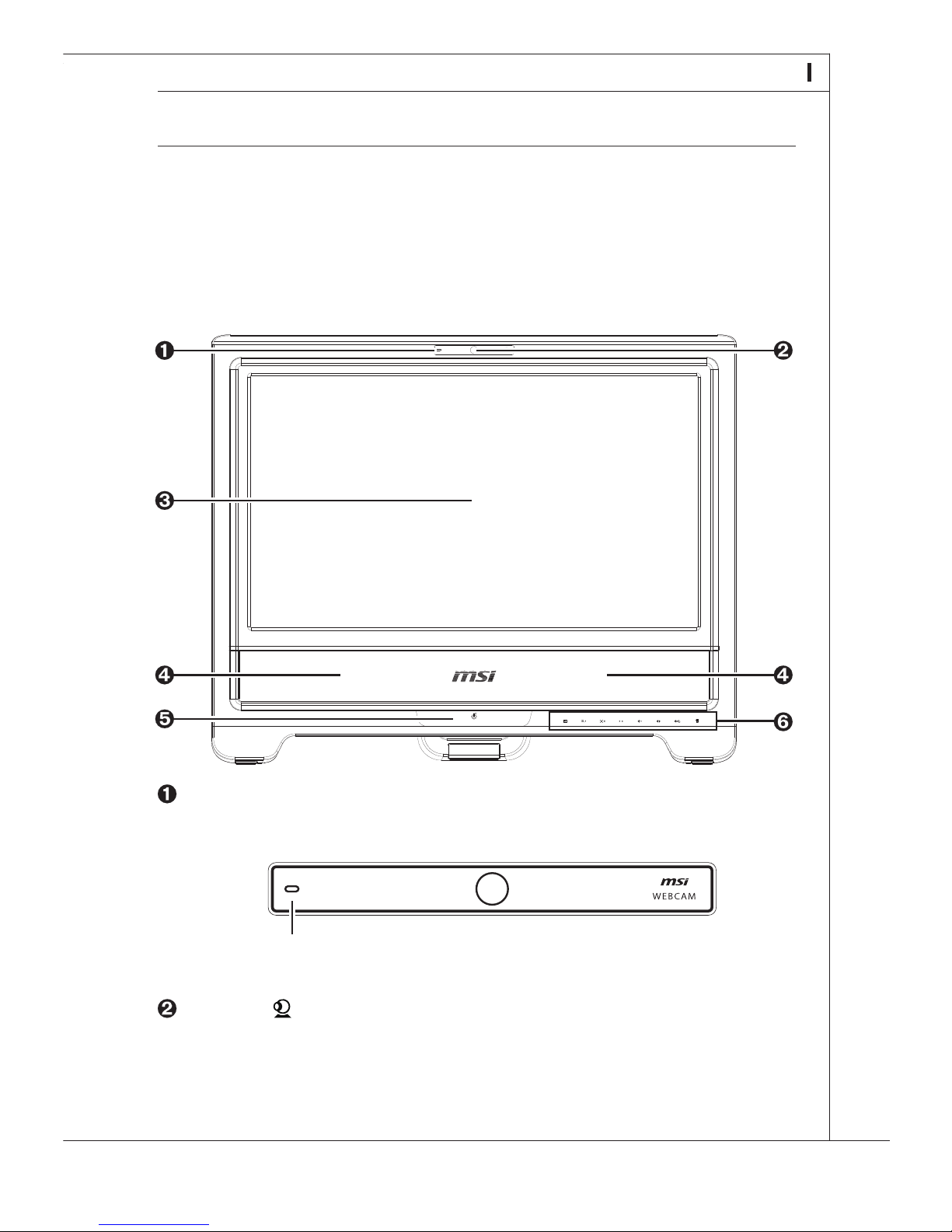
Please refer to the following illustration to identify the configurations on the front of your
system.
■ Front View
Packing Contents
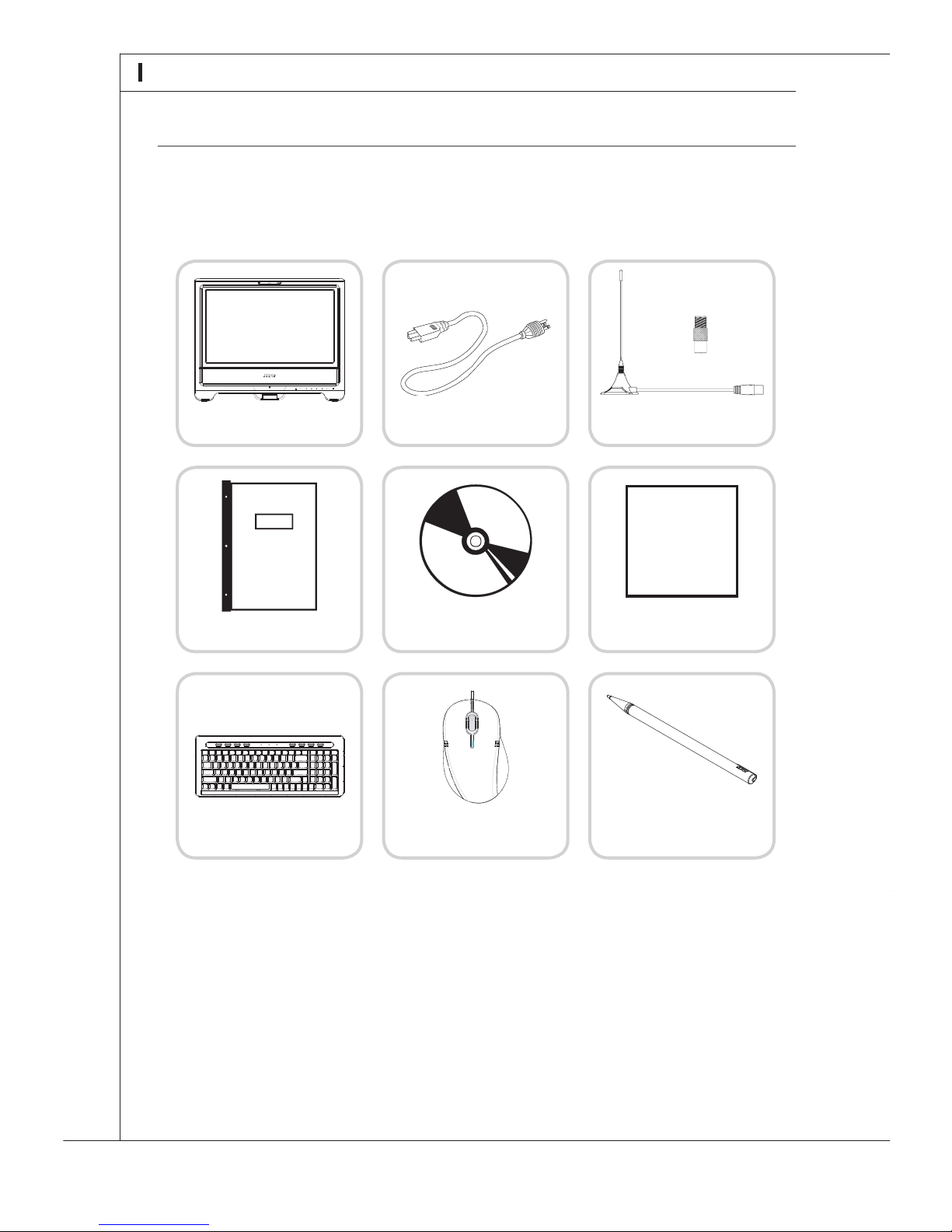
The following illustration shows the packing contents of your Wind Top AE2200 AIO PC.
Please contact us immediately if any of the following items is damaged or missing.
User Manual &
Quick Guide
Mouse (Optional)
Keyboard (Optional)
■ The TV antenna converter is provided for USA type only.
■ The blank DVD disk is for system recovery backup. (Please refer to page 19 for de-
tails.)
■ When installing the coaxial cable to the TV tuner antenna connector, it is necessary
to ensure that the metal shield is reliable connected to protective earthing system of
the building.
■ The illustrations are for your reference only and your packing contents may slightly
vary depending on the model you purchased.
Microphone
The built-in microphone can be used for video chatting online.
Webcam
The built-in webcam with the microphone can be used for picture taking, video recoding,
online conferencing and any other interactive applications.
Wind Top AE2200
AIO PC
Power Cord
TV Antenna &
TV Antenna Converter
Driver & Utility
& Blank DVD Disk
LCD Display Wiper
Stylus Touch
Pen (Optional)
ms i
Page 15
5
MS-6637
System Congurations
Please refer to the following illustration to identify the configurations on the front of your
system.
■ Front View
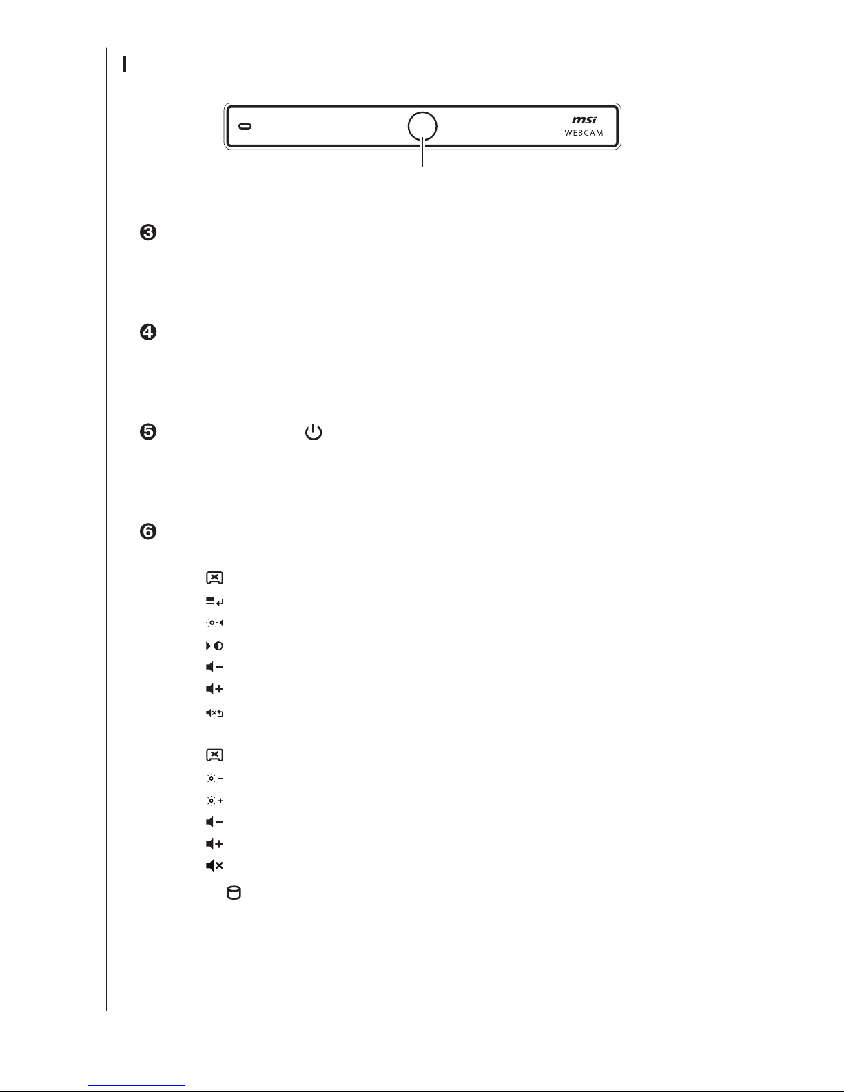
Microphone
The built-in microphone can be used for video chatting online.
Microphone
Webcam
The built-in webcam with the microphone can be used for picture taking, video recoding,
online conferencing and any other interactive applications.
Page 16
6
System Overview
Please refer to the following illustration to identify the congurations on the back of your
system.
■ Back View
Webcam
LCD Display
The 21.6-inch TFT LCD display is with an optimal resolution of 1920 X 1080 and standard
proportion of 16:9 widescreen (Full HD).
Stereo Speakers
The built-in stereo speakers deliver high quality sound blaster with stereo system and
Hi-Fi function supported.
Power Indicator
The power indicator illuminates in green when the AIO PC is on, illuminates in orange
when the AIO PC is in sleep mode and turns off when the AIO PC is off.
OSD Touch Pad (Please refer to page 29 for details.)
On the device with Scaler display card,
LCD Display On/ Off
Menu/ Enter
Brightness/ Left/ -
Contrast/ Right/ +
Volume-
Volume+
Mute/ Exit
On the device with MXM display card,
LCD Display On/ Off
Brightness-
Brightness+
Volume-
Volume+
Mute
HDD LED
The orange HDD LED is on when data is read from or written to the hard disk
drive.
■ “OSD” is the abbreviation of “On-Screen Display”.
Page 17
7
MS-6637
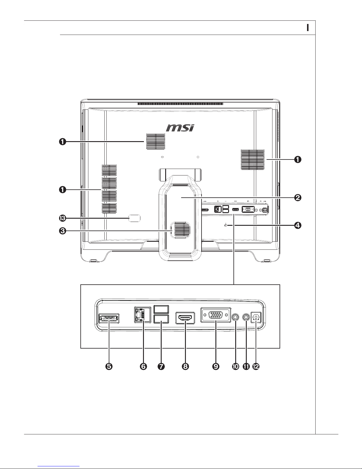
Please refer to the following illustration to identify the congurations on the back of your
system.
■ Back View
Page 18
8
System Overview
Ventilators
The ventilator on the enclosure is used for air convection and to prevent the equipment
from overheating. Do not cover the ventilator.
Stand
Cable Routing Hole
Route the cables through the cable routing hole to avoid cable spaghetti when connect-
ing devices.
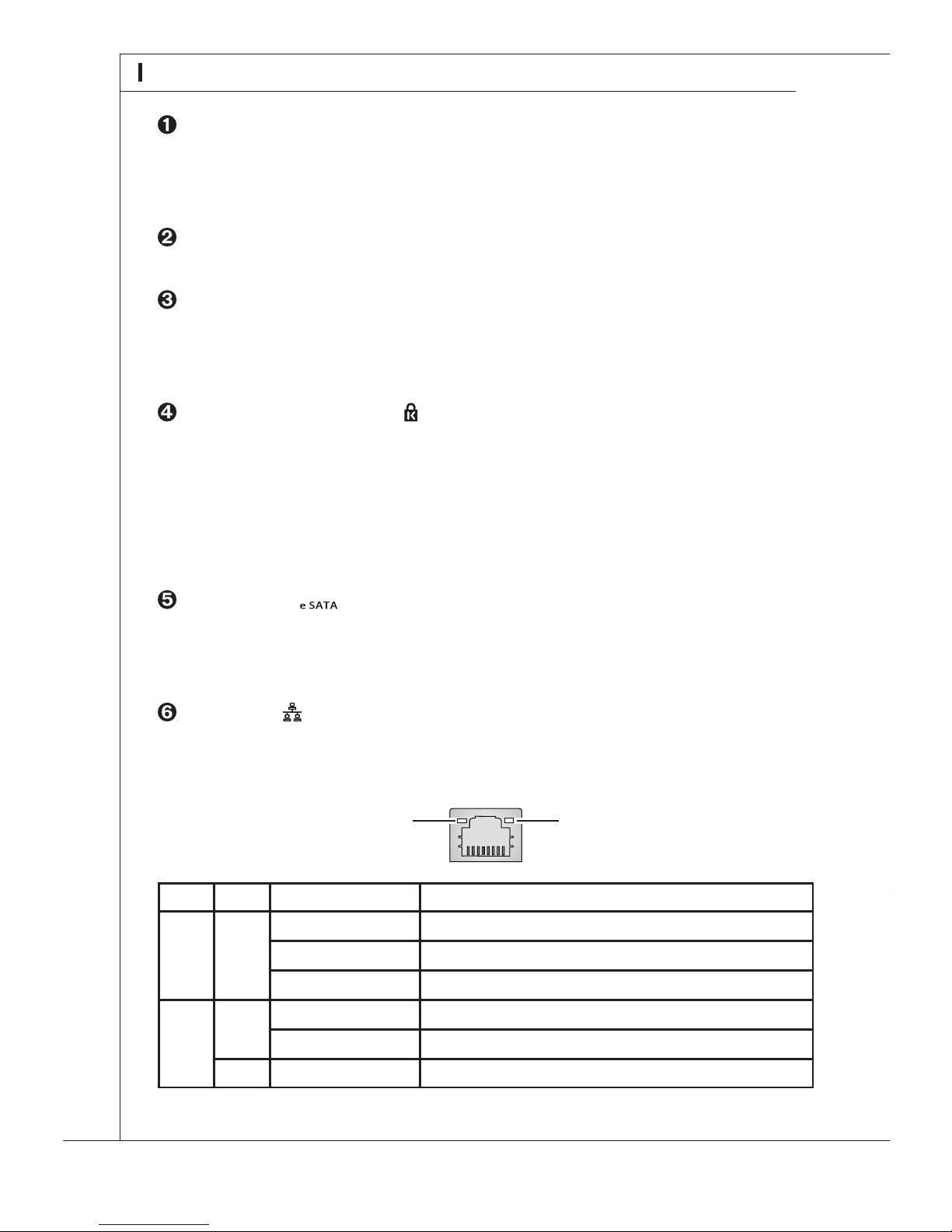
Kensington Lock Port
This AIO PC provides a Kensington lock port, which allows users to secure the AIO PC
in place with a key or some mechanical PIN device and attached through a rubberised
metal cable. The end of the cable has a small loop which allows the whole cable to be
looped around a permanent object, such as a heavy table or other similar equipment,
thus securing the AIO PC in place.
eSATA Port
The eSATA (External Serial ATA) port is provided for attaching the eSATA external hard
drive.
LAN Jack
The standard RJ-45 LAN jack is provided for connection to the Local Area Network (LAN).
You can connect a network cable to it.
Green/ OrangeYellow
Right
Left
LED Color LED State Condition
Yellow
Green
Orange
Off LAN link is not established.
On (steady state) LAN link is established.
On (brighter & pulsing) The computer is communicating with another computer on the LAN.
Off 10 Mbit/ sec data rate is selected.
On 100 Mbit/ sec data rate is selected.
On 1000 Mbit/ sec data rate is selected.
USB Ports .
The USB (Universal Serial Bus) port is provided for attaching USB devices such as mouse,
keyboard, printer, scanner, camera, PDA or other USB-compatible devices.
HDMI Port
On the device with MXM display card, the High-Denition Multimedia Interface (HDMI)
is an all-digital audio/ video interface capable of transmitting uncompressed streams.
HDMI supports all TV format, including standard, enhanced or high-denition video, plus
multi-channel digital audio on a single cable. On the device with Scaler display card, the
HDMI port is a HDMI-in function port and the LCD display can be used as a secondary
display of other HDMI devices.
VGA Port
The 15-pin-D-sub VGA port allows you to connect an external monitor or other standard
VGA-compatible device (such as a projector) for a great view of the computer display.
Microphone Jack (Pink)
This is a connector for microphone.
Headphone Jack (Green)
This is a connector for headphones or speakers.
Optical S/PDIF-Out Jack
This S/PDIF (Sony & Philips Digital Interconnect Format) jack is provided for digital audio
transmission to external speakers through an optical ber cable.
TV Tuner Antenna Connector
This connector is for TV antenna.
Page 19
9
MS-6637
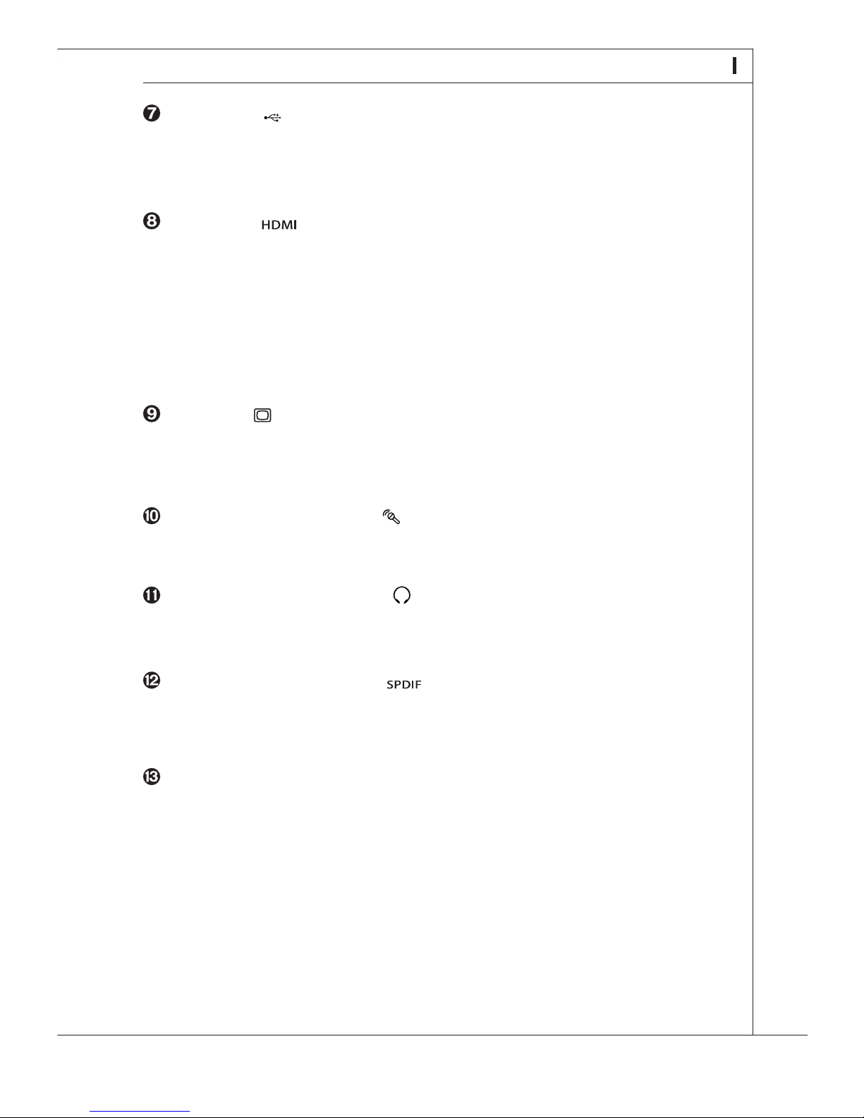
USB Ports .
The USB (Universal Serial Bus) port is provided for attaching USB devices such as mouse,
keyboard, printer, scanner, camera, PDA or other USB-compatible devices.
HDMI Port
On the device with MXM display card, the High-Denition Multimedia Interface (HDMI)
is an all-digital audio/ video interface capable of transmitting uncompressed streams.
HDMI supports all TV format, including standard, enhanced or high-denition video, plus
multi-channel digital audio on a single cable. On the device with Scaler display card, the
HDMI port is a HDMI-in function port and the LCD display can be used as a secondary
display of other HDMI devices.
VGA Port
The 15-pin-D-sub VGA port allows you to connect an external monitor or other standard
VGA-compatible device (such as a projector) for a great view of the computer display.
Microphone Jack (Pink)
This is a connector for microphone.
Headphone Jack (Green)
This is a connector for headphones or speakers.
Optical S/PDIF-Out Jack
This S/PDIF (Sony & Philips Digital Interconnect Format) jack is provided for digital audio
transmission to external speakers through an optical ber cable.
TV Tuner Antenna Connector
This connector is for TV antenna.
Page 20
10
System Overview
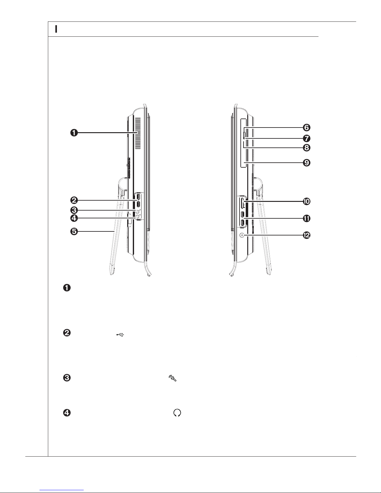
Ventilators
The ventilator on the enclosure is used for air convection and to prevent the equipment
from overheating. Do not cover the ventilator.
USB Ports
The USB (Universal Serial Bus) port is provided for attaching USB devices such as mouse,
keyboard, printer, scanner, camera, PDA or other USB-compatible devices.
Microphone Jack (Pink)
This is a connector for microphone.
Headphone Jack (Green)
This is a connector for headphones or speakers.
Please refer to the following illustration to identify the congurations on the side of your
system.
■ Side View
Stand
Eject Button
Press the eject button to open the optical disk drive.
ODD LED
The yellow ODD LED is on when CD/ DVD is read from or written to the optical disk
drive.
Eject Hole
Insert a thin, straight object (such as a paper clip) into the eject hole to open the optical
disk drive manually if the eject button does not work.
Optical Disk Drive
Card Reader Drive
The built-in card reader may support various types of memory card, such as XD (eX-
treme Digital), SD (Secure Digital), SDHC (SD High Capacity), MS (Memory Stick), MS
Pro (Memory Stick Pro) or MMC (Multi-Media Card) cards that usually used in devices
like digital cameras, MP3 players, mobile phones and PDAs. Contact the local dealer
for further information and please be noted that the supported memory cards may vary
without notice.
USB Ports
The USB (Universal Serial Bus) port is provided for attaching USB devices such as mouse,
keyboard, printer, scanner, camera, PDA or other USB-compatible devices.
Power Button
Press the power button to turn the system on and off.
Page 21
11
MS-6637
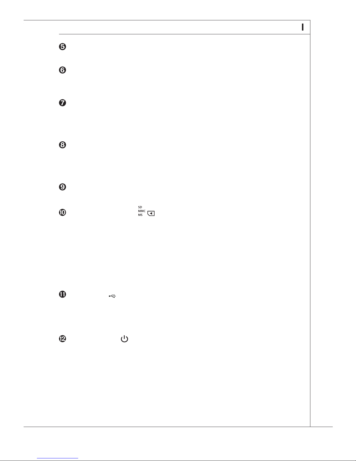
Stand
Eject Button
Press the eject button to open the optical disk drive.
ODD LED
The yellow ODD LED is on when CD/ DVD is read from or written to the optical disk
drive.
Eject Hole
Insert a thin, straight object (such as a paper clip) into the eject hole to open the optical
disk drive manually if the eject button does not work.
Optical Disk Drive
Card Reader Drive
The built-in card reader may support various types of memory card, such as XD (eX-
treme Digital), SD (Secure Digital), SDHC (SD High Capacity), MS (Memory Stick), MS
Pro (Memory Stick Pro) or MMC (Multi-Media Card) cards that usually used in devices
like digital cameras, MP3 players, mobile phones and PDAs. Contact the local dealer
for further information and please be noted that the supported memory cards may vary
without notice.
USB Ports
The USB (Universal Serial Bus) port is provided for attaching USB devices such as mouse,
keyboard, printer, scanner, camera, PDA or other USB-compatible devices.
Power Button
Press the power button to turn the system on and off.
Page 22
12
System Overview
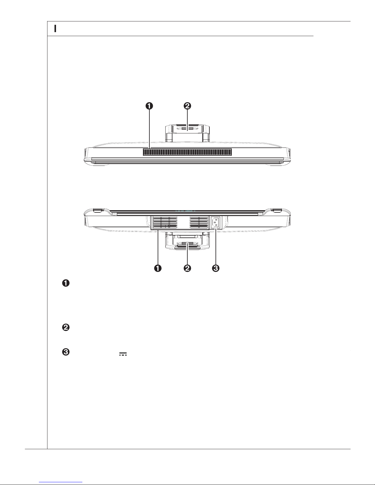
Ventilators
The ventilator on the enclosure is used for air convection and to prevent the equipment
from overheating. Do not cover the ventilator.
Stand
Power Jack
Power supplied through this jack supplies power to your personal computer.
Please refer to the following illustration to identify the congurations on the top and bot-
tom of your system.
■ Top and Bottom View
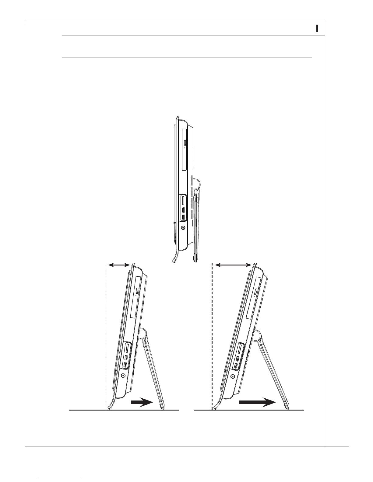
Step 1. Place your system on a at and steady surface such as a table or desk.
Step 2. Pull the stand open and tilt the LCD display to an angle of between 8 and
How to Position the System
■ While adjusting the angle, do not exert excessive pressure on your system to eliminate
a risk of mechanical damage.
Page 23
13
MS-6637
Step 1. Place your system on a at and steady surface such as a table or desk.
Step 2. Pull the stand open and tilt the LCD display to an angle of between 8 and
14 degrees to suit your preference. This helps to reduce your eye strain and
muscle fatigue.
How to Position the System
■ While adjusting the angle, do not exert excessive pressure on your system to eliminate
a risk of mechanical damage.
14º0º8º0º
Page 24
14
System Overview
How to Use the Keyboard
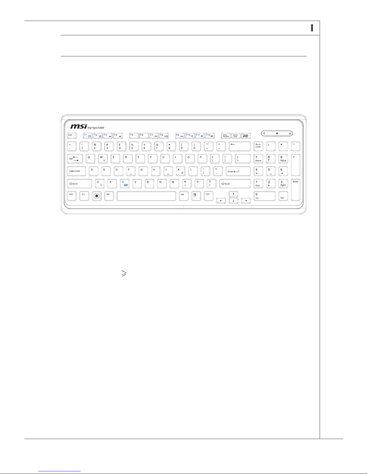
Wind Top AE2200 AIO PC packs with a wired keyboard StarType ES500 that helps
your control of the system.
■ Layout
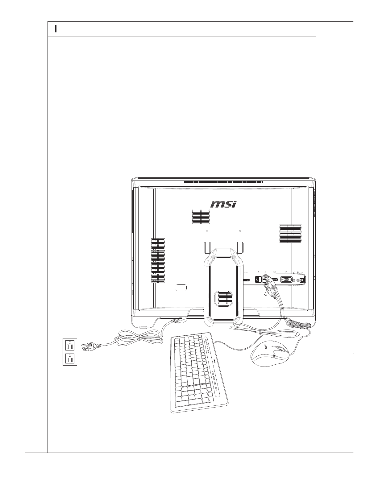
How to Connect the Peripheral Devices
Step 1. Connect the USB-interfaced mouse and keyboard to the USB ports on the back
panel.
Step 2. Connect the network device to the LAN port.
Step 3. Connect the audio devices such as headphone and microphone to the audio
jacks if necessary.
Step 4. Connect the power cord to the power jack.
■ We suggest that you connect the power cord to your system first and then connect to
the socket-outlet for safety concerns.
■ Specications
- Weight: 440 g
- Cable Length: 150 cm
- USB interface for all Windows
- New isolated keycap for easy typing
- Keystroke life cycle 12 million times
- Low prole with silk printing technology
- Dimension: 376 mm (W) X 155 mm (L) X 22 mm (H)
- Compatible with EU/ JP/ KR/ UK/ US language layout
■ Features
- Built-in function hot keys
- Compact size for space saving
- Especially t for MSI
- Multimedia function keys with AIO PC
- Compatible with Windows
- Soft-touch and tactile feedback for comfortable typing
- New concept elegant and slim keyboard in streamline shape
- Access favorite websites and applications with one touch hot keys
■ The illustration of keyboard is for reference only. Actual product specications may
vary with territories.
Page 25
15
MS-6637
How to Use the Keyboard
Wind Top AE2200 AIO PC packs with a wired keyboard StarType ES500 that helps
your control of the system.
■ Layout
■ Specications
- Weight: 440 g
- Cable Length: 150 cm
- USB interface for all Windows® OS
- New isolated keycap for easy typing
- Keystroke life cycle 12 million times
- Low prole with silk printing technology
- Dimension: 376 mm (W) X 155 mm (L) X 22 mm (H)
- Compatible with EU/ JP/ KR/ UK/ US language layout
■ Features
- Built-in function hot keys
- Compact size for space saving
- Especially t for MSITM LCD display
- Multimedia function keys with AIO PC
- Compatible with Windows® 2000/ ME/ XP/ Vista/ 7
- Soft-touch and tactile feedback for comfortable typing
- New concept elegant and slim keyboard in streamline shape
- Access favorite websites and applications with one touch hot keys
■ The illustration of keyboard is for reference only. Actual product specications may
vary with territories.
Page 26
16
System Overview
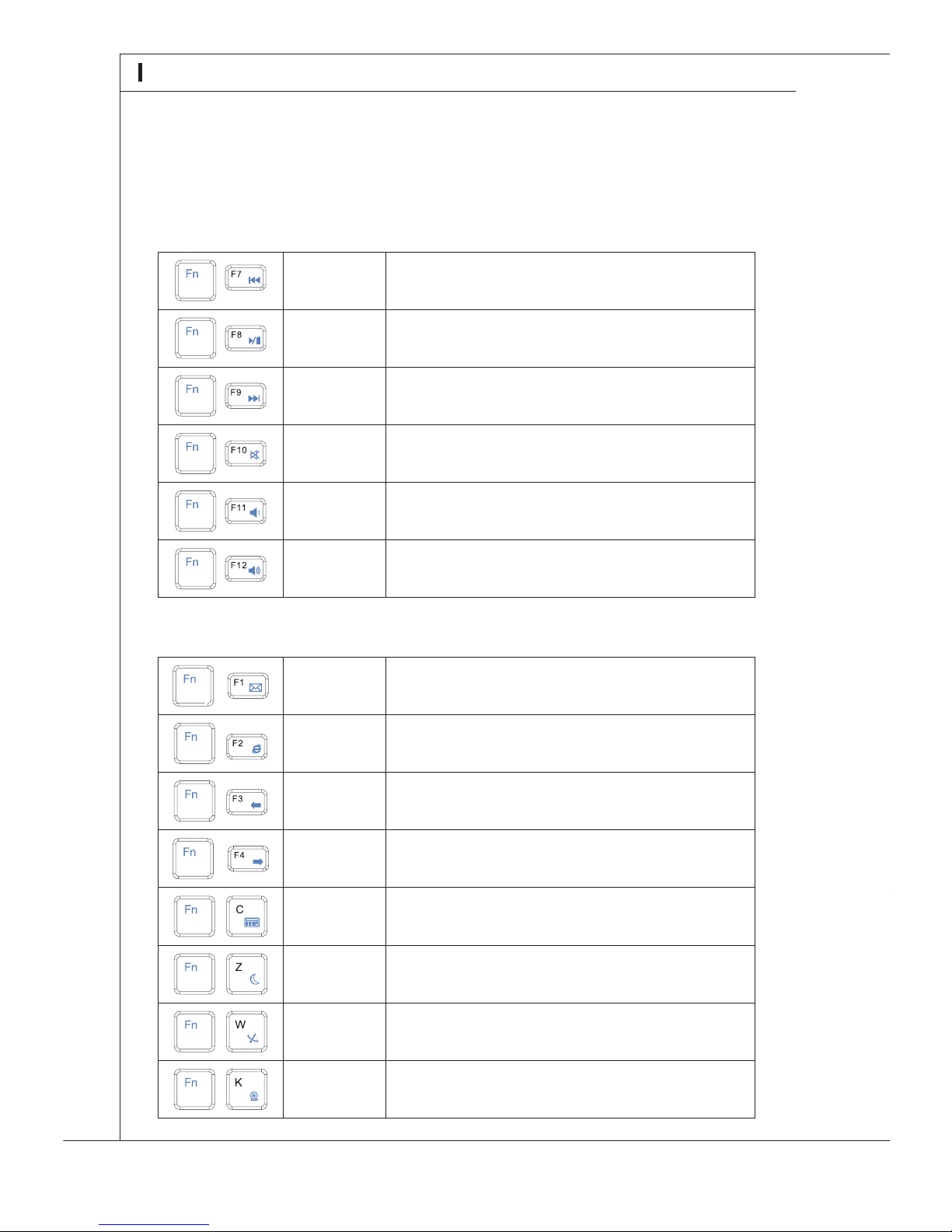
Please refer to the following illustration to identify the function keys of your keyboard.
System Booting Setup for the First Time
■ Multimedia Keys
Fn + F7
Backward to previous track
Fn + F8
Play and pause
Fn + F9
Forward to next track
Fn + F10
Mute function
Fn + F11
Volume down
Fn + F12
Volume up
■ Hot Keys
Fn + F1
Launch the default E-Mail applications
Fn + F2
Lanuch the default internet browser and go to the default home page
Fn + F3
Back to the previous web page
Fn + F4
Forward to the next web page
Fn + C
Calculator
Fn + Z
Sleep mode
Fn + W
Turn on/ o the wireless LAN
Fn + K
Camera
For the rst-time use, you will need to go over the following steps to start using your Wind
Top AE2200 AIO PC. The entire booting setup will take you around 90 minutes.
Step 1. Click [OK] to ensure the AC power connection and do not turn it off while
Step 2. Windows setup starts running. Please wait until Windows setup nishes the
Step 3. Select the language of operation system you need and click [Next] to con-
Step 4. Choose the “Country or region”, “Time and currency” and “Keyboard layout”
Step 5. Please read the license terms. Check the “I accept the license terms” box and
Step 6. Enter a user name/ password and choose a picture for your user account. Click
Step 7. Type a computer name and choose a desktop background you want. Click
Step 8. Select “Use recommended settings” for “Help protect Windows automati-
Step 9. Review your time and date settings. Click [Next] to continue.
Step 10. A “Thank you” page comes out. Click [Start] to let Windows check your system
Step 11.
Step 12. The software is being installed. Please do not turn off the computer when
Step 13. The system enters the Vista OS to start its personalized settings. After the per-
Page 27

17
MS-6637
System Booting Setup for the First Time
For the rst-time use, you will need to go over the following steps to start using your Wind
Top AE2200 AIO PC. The entire booting setup will take you around 90 minutes.
Step 1. Click [OK] to ensure the AC power connection and do not turn it off while
Windows setup is running.
Step 2. Windows setup starts running. Please wait until Windows setup nishes the
progress loading.
Step 3. Select the language of operation system you need and click [Next] to con-
tinue.
Step 4. Choose the “Country or region”, “Time and currency” and “Keyboard layout”
you need. Click [Next] to continue.
Step 5. Please read the license terms. Check the “I accept the license terms” box and
click [Next] to continue.
Step 6. Enter a user name/ password and choose a picture for your user account. Click
[Next] to proceed.
Step 7. Type a computer name and choose a desktop background you want. Click
[Next] to continue.
Step 8. Select “Use recommended settings” for “Help protect Windows automati-
cally.”
Step 9. Review your time and date settings. Click [Next] to continue.
Step 10. A “Thank you” page comes out. Click [Start] to let Windows check your system
performance.
Step 11.
The “Software Installation Menu” pops up. Please click on “Install” to begin
installing.
Step 12. The software is being installed. Please do not turn off the computer when
software installation is running. When the progress bar completes loading,
click [Finish] to continue.
Step 13. The system enters the Vista OS to start its personalized settings. After the per-
sonalized settings are done, the IdeaCom Touch Screen Calibration Tool pops
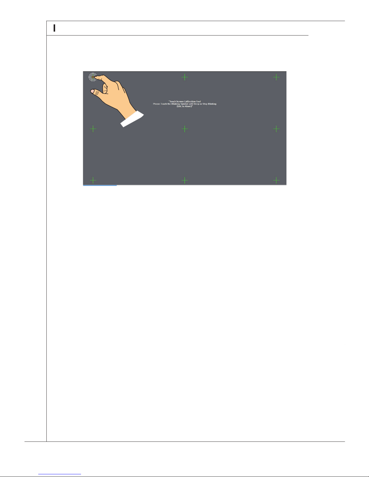
up. Please follow the instruction on the screen to press each symbol: “Please
Touch the Blinking Symbol until Beep or Stop Blinking (ESC to Abort).”
Page 28
18
System Overview
For the rst-time use, it is required for you to create a system recovery disk as the back-
up solution for any accidents. Before moving forward, please make sure your system
booting setup is complete and go over the following procedures to get it done.
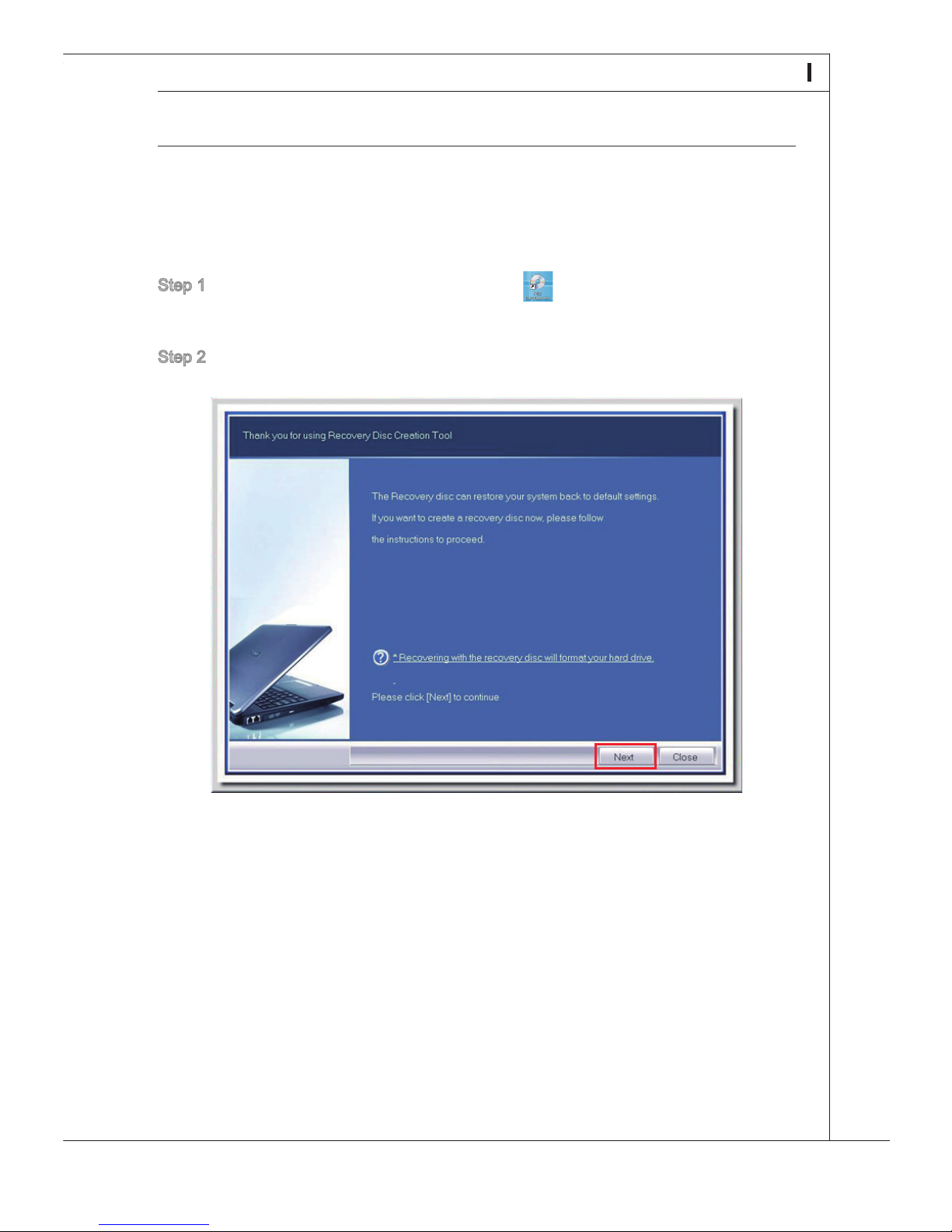
Step 1. Select the icon of “MSI BurnRecovery” on the desktop screen and click
Step 2. Click [Next] to start the image creation of the recovery disk.
How to Creat the System Recovery Disk
Step 14. On completion of the touch screen calibration, the system reboots automatically
and brings forth the recovery disc menu. The recovery disc can restore your
system to default settings. If you wish to create the recovery disc now, please
click [OK].
Step 15. After nishing creating the recovery disc, the system enters the Vista OS. The
touch screen will be automatically activated and post the default home page
of MSI® Wind Touch. Your AIO PC will be ready for use right now. Have fun
with it!
Page 29
19
MS-6637
For the rst-time use, it is required for you to create a system recovery disk as the backup solution for any accidents. Before moving forward, please make sure your system
booting setup is complete and go over the following procedures to get it done.
Step 1. Select the icon of “MSI BurnRecovery” on the desktop screen and click
through it.
Step 2. Click [Next] to start the image creation of the recovery disk.
How to Creat the System Recovery Disk
Page 30
20
System Overview
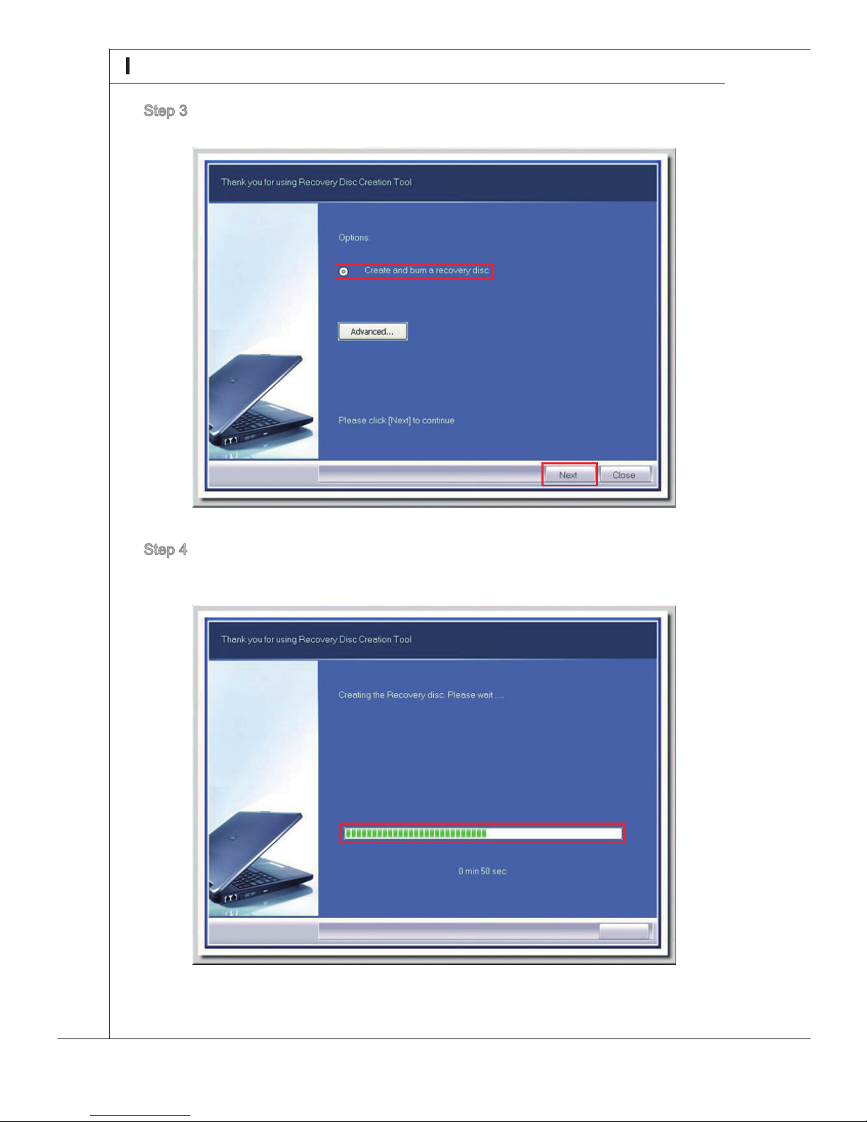
Step 3. Select “Create and burn a recovery disk” and click [Next] to continue.
Step 4. The progress bar starts running to create the image of recovery disk. It takes
around 2-3 minutes to nish the porcessing.
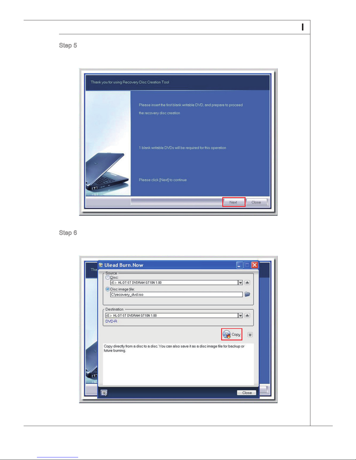
Step 5. Insert a blank DVD-R disk (free bundle with the standard package) and click
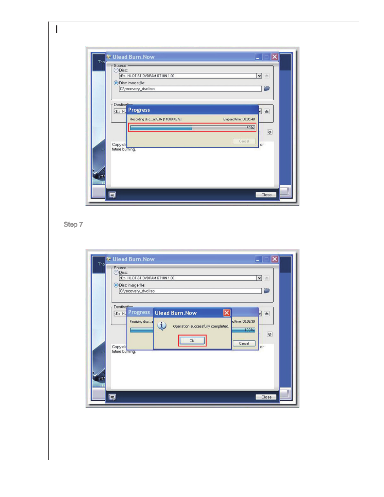
Step 6. The user interface of Ulead Burn. Now pops out. Click [Copy] to start the burn-
Page 31
21
MS-6637
Step 5. Insert a blank DVD-R disk (free bundle with the standard package) and click
[Next] to continue.
Step 6. The user interface of Ulead Burn. Now pops out. Click [Copy] to start the burn-
ing progress. It takes around 9 minutes to nish the processing.
Page 32
22
System Overview
Step 7. The message of “Operation successfully completed” pops out. Click [OK] and
take out the disk to nish the recovery disk creation.
Touch Panel Calibration
Wind Top AE2200 AIO PC has touch panel function. If the mouse cursor can not match
the move, users could use the IdeaCom TSC tool installed in system to adjust the ac-
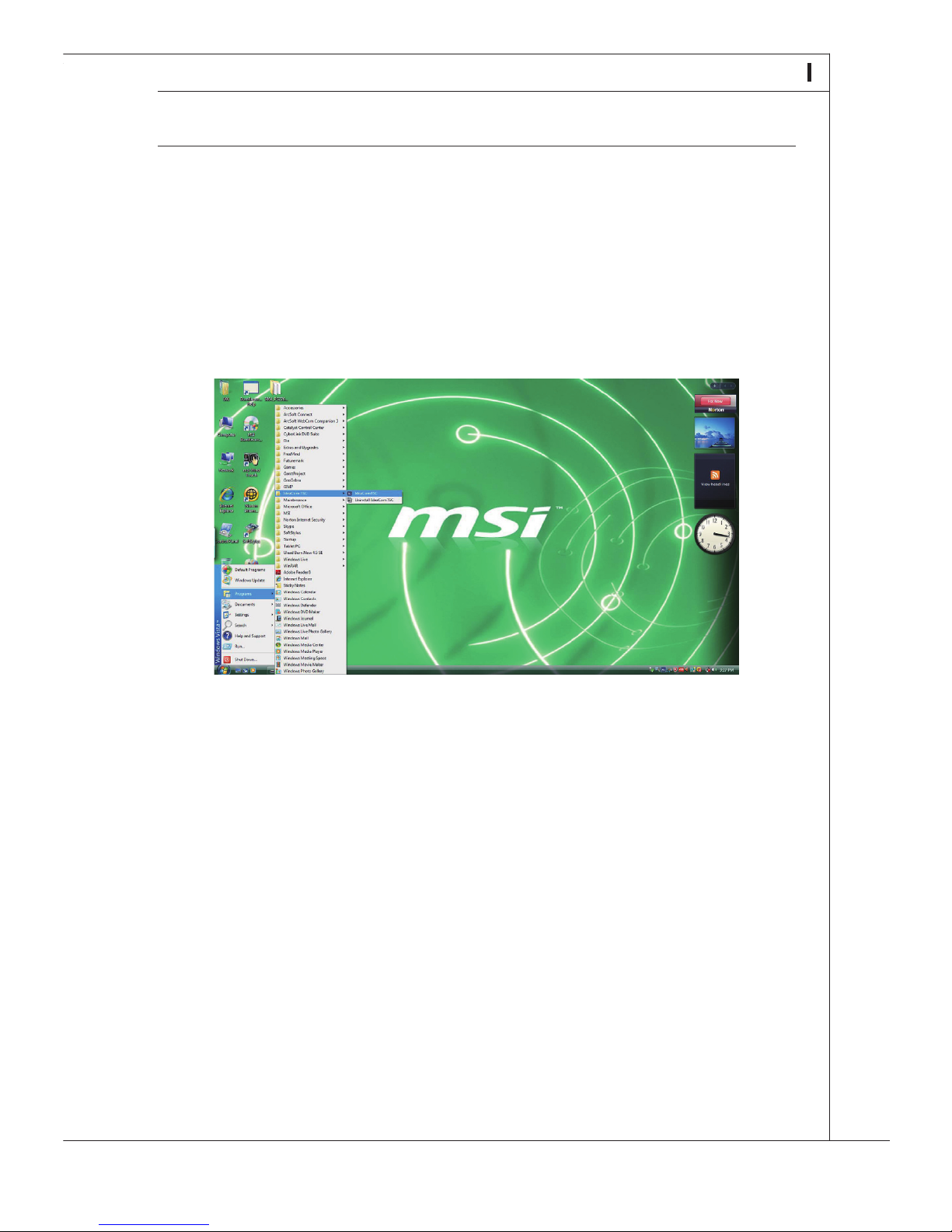
curacy of the touch panel. Please go over the following steps to get it done.
Step 1. Open the IdeaCom TSC tool by clicking from Start > Programs > IdeaCom
Step 2. Then, the IdeaCom Touch Panel Controller setup utility appears as below.
Page 33
23
MS-6637
Touch Panel Calibration
Wind Top AE2200 AIO PC has touch panel function. If the mouse cursor can not match
the move, users could use the IdeaCom TSC tool installed in system to adjust the ac-
curacy of the touch panel. Please go over the following steps to get it done.
Step 1. Open the IdeaCom TSC tool by clicking from Start > Programs > IdeaCom
TSC > IdeaCom TSC.
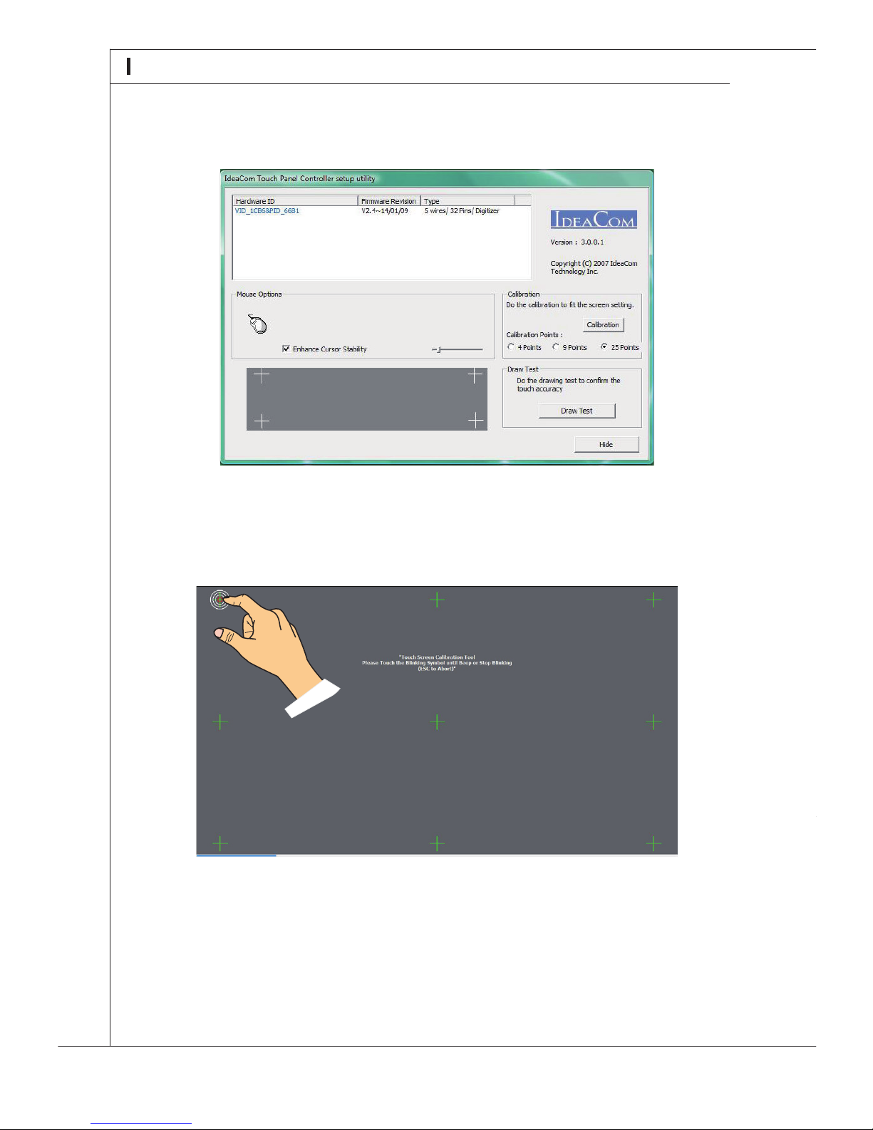
Step 2. Then, the IdeaCom Touch Panel Controller setup utility appears as below.
Click on “Calibration” to adjust the accuracy of the touch panel. It has three
modes: 4 points, 9 points and 25 points. We suggest that the user choose
9 points to adjust touch panel. If the user desires the most exactness, then
choose 25 points instead.
Page 34
24
System Overview
Step 3. Please follow the instruction on the screen to press each symbol: Please Touch
the Blinking Symbol until Beep or Stop Blinking (ESC to Abort).
■ Do not touch the screen directly with any sharp-pointed object.
■ Actual product specications may very with territories.
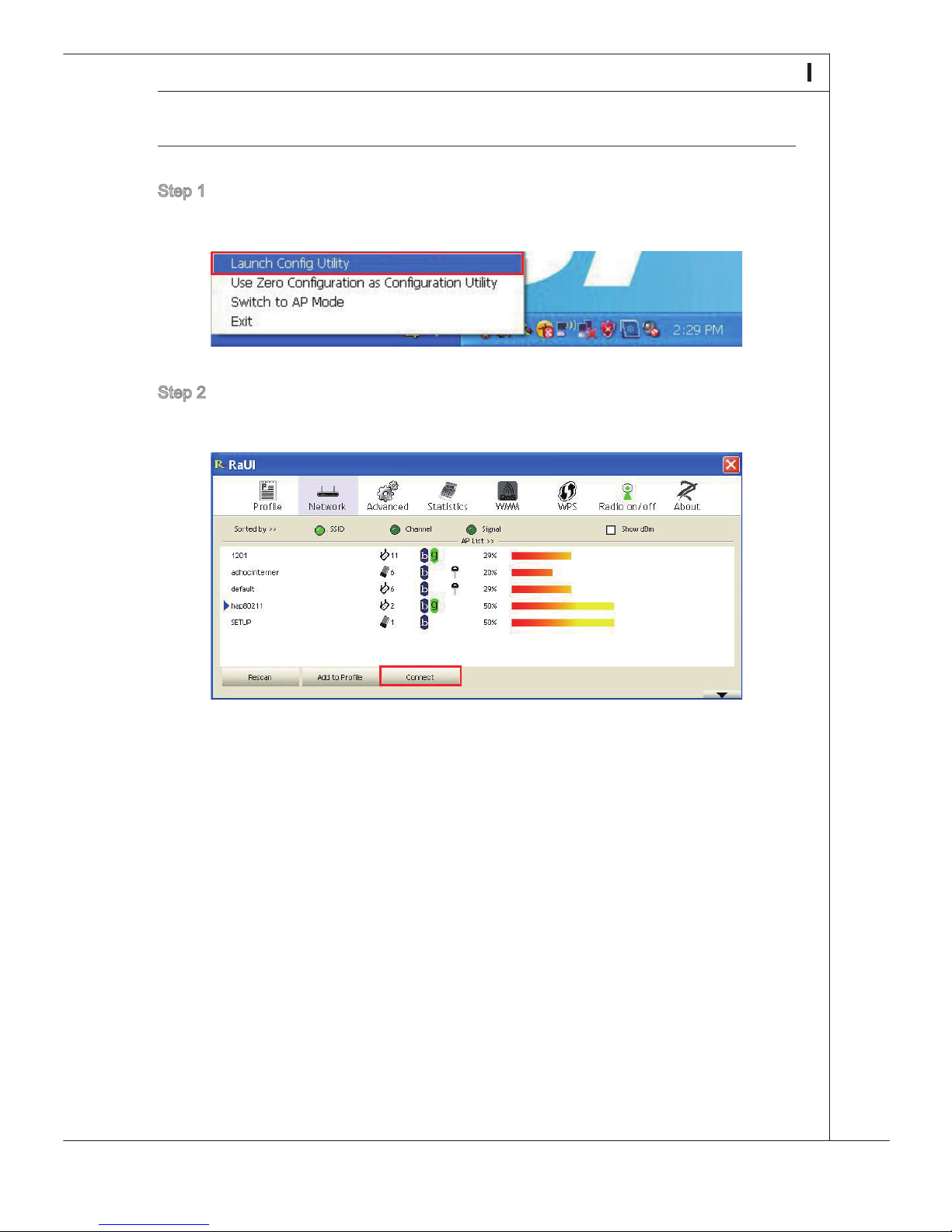
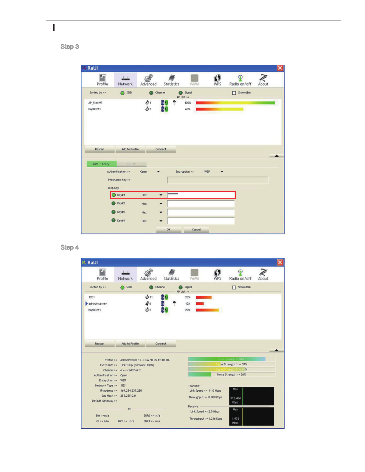
Step 1. Right-click the Ralink Wireless LAN Card status icon in the lower right corner
Step 2. The window displays some available wireless networks. Choose a network
Wireless LAN Connection
Page 35
25
MS-6637
Step 1. Right-click the Ralink Wireless LAN Card status icon in the lower right corner
and then click Launch Cong Utility.
Step 2. The window displays some available wireless networks. Choose a network
and then click Connect.
Wireless LAN Connection
Page 36
26
System Overview
Step 3. There may prompts you to enter a key. Type the network key and then click
OK.
Step 4. Now, you’re ready to browse the Web wirelessly.
SRS Premium Sound
SRS Premium Sound is a comprehensive suite of state-of-the-art
audio technologies that deliver a superior entertainment experience
for playback of music, video and game content on the PC.
With SRS Premium Sound your audio entertainment experience will
sound better - more natural and immersive, with deeper bass, clearer
dialog and outstanding surround sound.
Features:
Using the SRS Premium Sound GUI
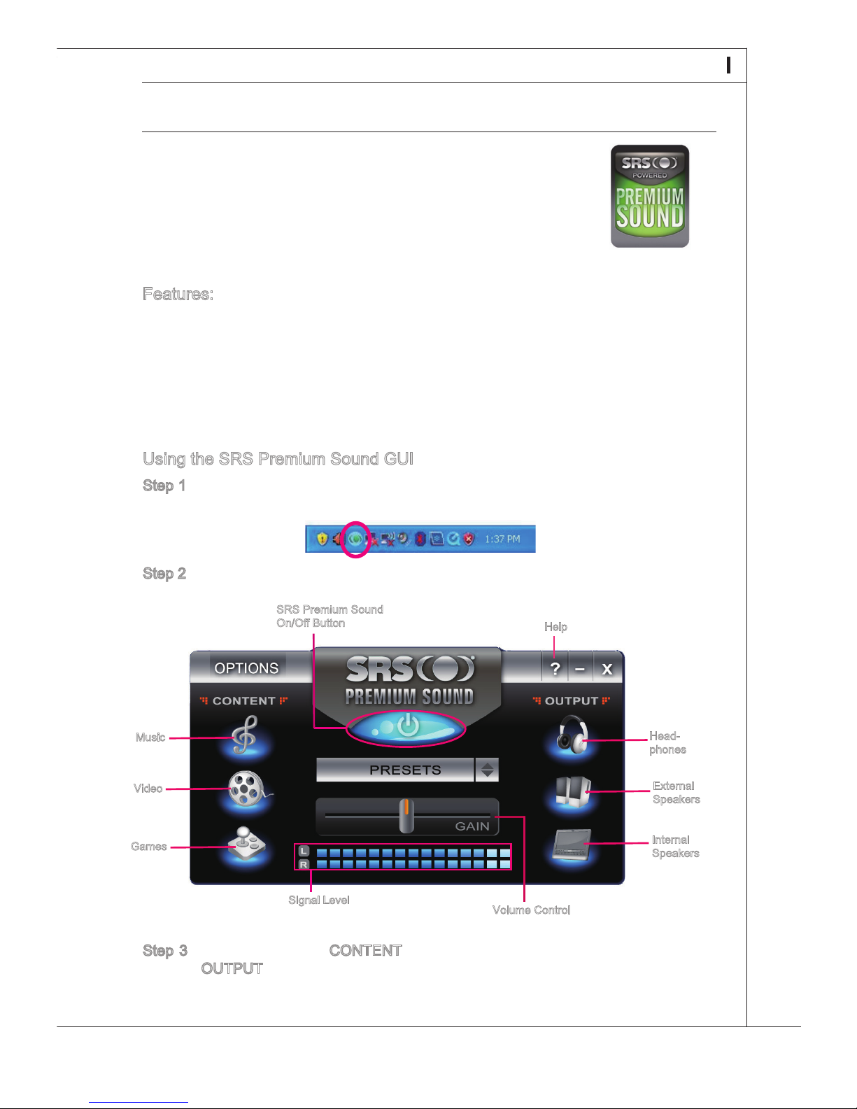
Step 1. Double-click the SRS Premium Sound tray icon at the lower right corner of
Step 2. The SRS Premium Sound control panel pops up.
Step 3. Choose the audio CONTENT you are listening to and specify your audio
Music
Video
Games
Page 37
27
MS-6637
SRS Premium Sound
SRS Premium Sound is a comprehensive suite of state-of-the-art
audio technologies that deliver a superior entertainment experience
for playback of music, video and game content on the PC.
With SRS Premium Sound your audio entertainment experience will
sound better - more natural and immersive, with deeper bass, clearer
dialog and outstanding surround sound.
Features:
Premium audio experience for music, video and games on the PC
Immersive surround sound experience from internal or external speakers
and even headphones
Greater volume without degrading audio quality
Crystal clear dialog
Deep, rich bass
Using the SRS Premium Sound GUI
Step 1. Double-click the SRS Premium Sound tray icon at the lower right corner of
the screen to launch the SRS Premium Sound GUI (Graphical User Interface).
Step 2. The SRS Premium Sound control panel pops up.
Step 3. Choose the audio CONTENT you are listening to and specify your audio
OUTPUT device. The SRS Premium Sound will automatically process the
specied audio signals to deliver enhanced audio performance.
■
■
■
■
■
Music
Video
Games
Headphones
External
Speakers
Internal
Speakers
Volume Control
Signal Level
Help
SRS Premium Sound
On/O Button
Page 38
28
System Overview
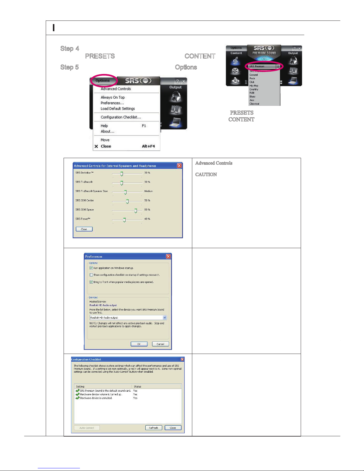
Step 4. You may also try choosing an option from the
PRESETS according to your audio CONTENT.
Step 5. For advanced settings, click the Options tab.
Advanced Controls allows for specic control of
SRS tuning parameters.
CAUTION: These settings are very sensitive and
should be used by advanced users. The following
parameters are provided for External Speakers and
Headphones.
Denition: adjusts the high frequencies
TruBass: adjusts the bass or low frequencies
Speaker Size: should be used to select the
size of the speakers (tiny to largest)
Center: adjusts the center-channel sound
3D Space: adjusts the amount and width of
the sound stage
Focus: adjusts the frequencies that include
vocals/voice
■
■
■
■
■
■
Run application on Windows startup: controls
whether or not SRS Premium Sound runs
when windows starts.
Bring to front when popular media players
are opened: sets whether or not the control
panel is brought to front when related audio
applications start.
Devices: species the preferred device to
which SRS Premium Sound should send processed audio for playback.
Hosted Device: displays the current device
being used. The default setting will enable
Premium Sound.
■
■
■
■
An intuitive & user-friendly troubleshooting menu
is available via the Conguration Checklist option.
The PRESETS will vary according to
the CONTENT selected.
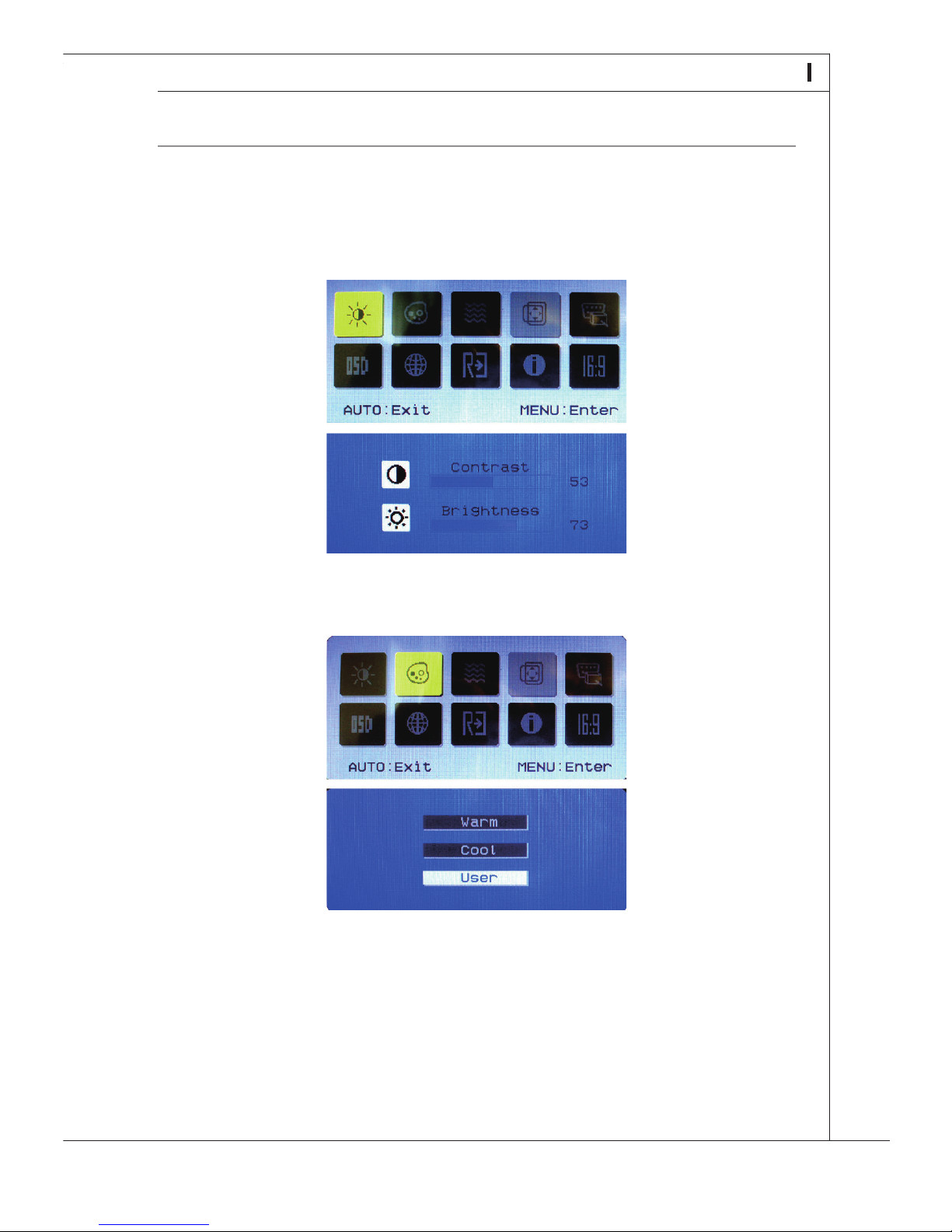
On-Screen Display (OSD) Touch Pad Menu
OSD touch pad menu is only enabled on the device with Scaler display card. You will
see below setup menu appear if you touch the OSD touch pad.
Press to enter this item to adjust contrast and brightness. Available setting options:
[Contrast] and [Brightness].
Press to enter this item to adjust color. Available setting options: [Warm], [Cool] and
[User].
Page 39
29
MS-6637
On-Screen Display (OSD) Touch Pad Menu
OSD touch pad menu is only enabled on the device with Scaler display card. You will
see below setup menu appear if you touch the OSD touch pad.
Press to enter this item to adjust contrast and brightness. Available setting options:
[Contrast] and [Brightness].
Press to enter this item to adjust color. Available setting options: [Warm], [Cool] and
[User].
Page 40
30
System Overview
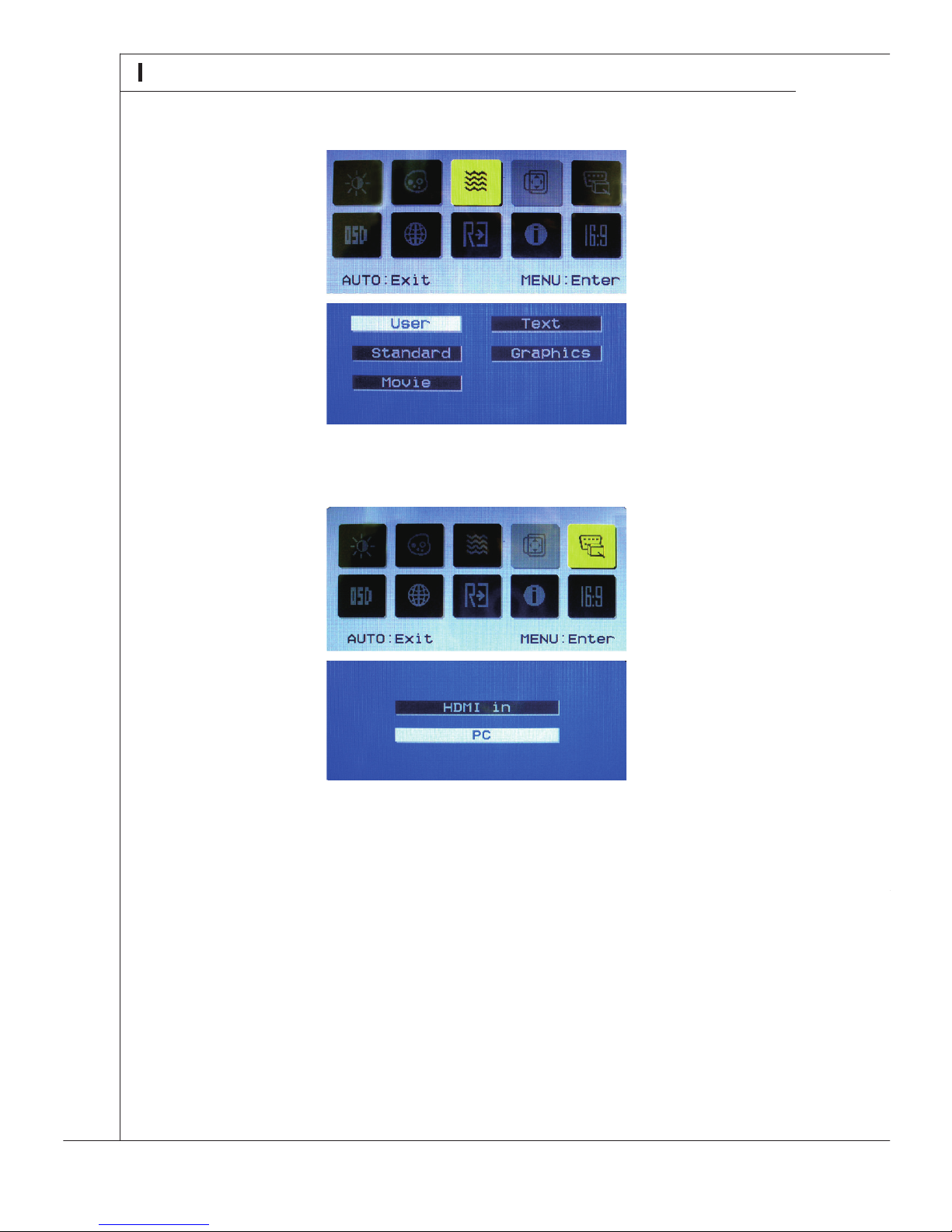
Press to enter this item to adjust video. Available setting options: [User], [Standard],
[Movie], [Text] and [Graphics].
Press to enter this item to adjust signal source. Available setting options: [HDMI in]
and [PC].
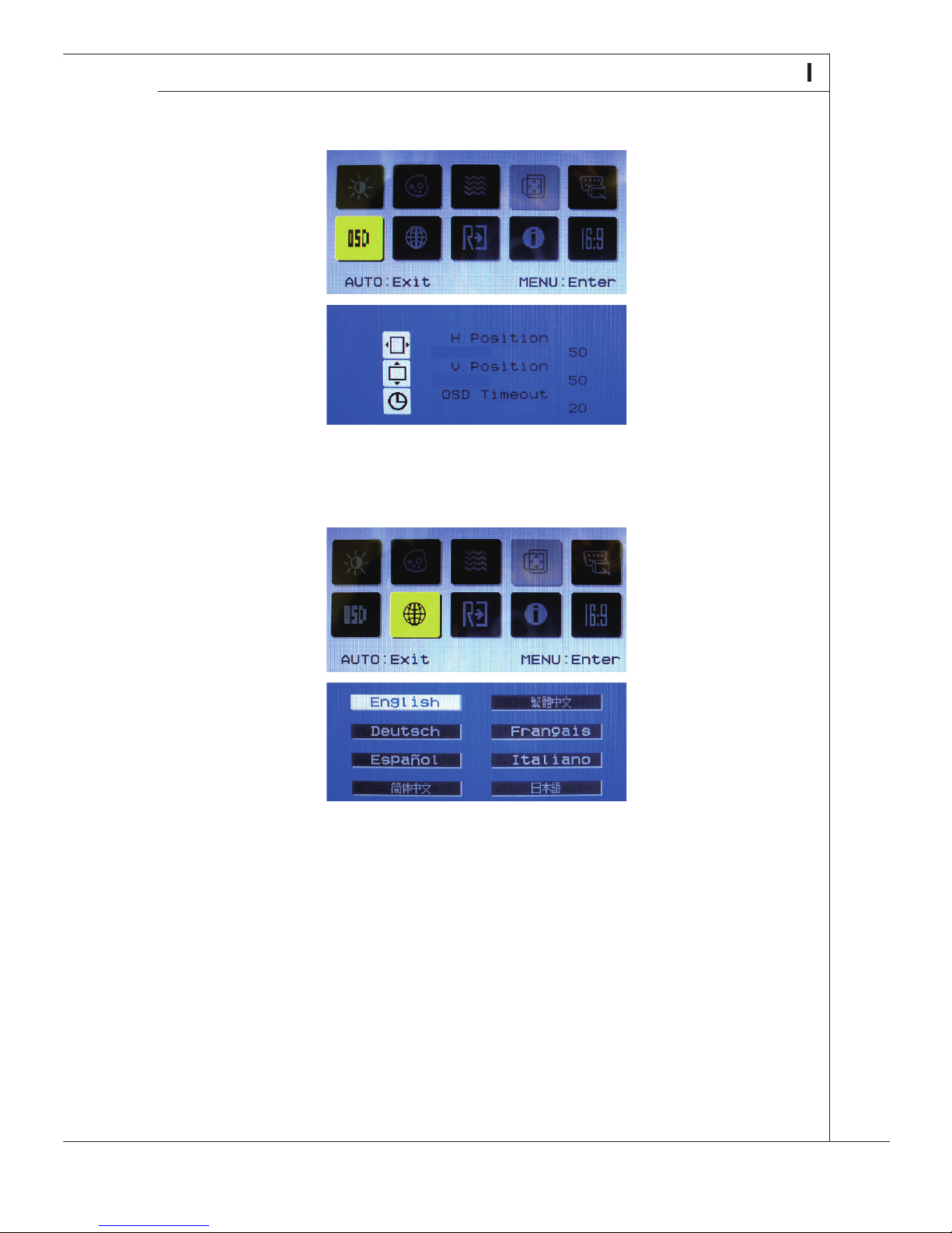
Press to enter this item to adjust OSD. Available setting options: [H. Position], [V. Posi-
tion] and [OSD Timeout].
Press to enter this item to adjust language. Available setting options: [English], [Ger-
man], [Spanish], [Simplied Chinese], [Traditional Chinese], [French], [Italian] and
[Japanese].
Page 41
31
MS-6637
Press to enter this item to adjust OSD. Available setting options: [H. Position], [V. Posi-
tion] and [OSD Timeout].
Press to enter this item to adjust language. Available setting options: [English], [German], [Spanish], [Simplied Chinese], [Traditional Chinese], [French], [Italian] and
[Japanese].
Page 42
32
System Overview
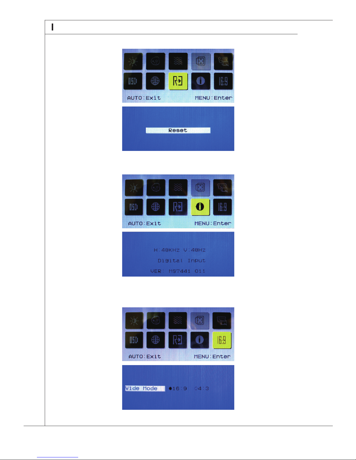
Press to enter this item to reset.
Press to enter this item to read informaion.
Press to enter this item to adjust wide screen. Available setting options: [16:9] and
[4:3].
 Loading...