

Page 1

Chapter 1. Introduction
Chapter 1. Getting Started
Introduction
Getting Started
Thank you for purchasing the MS-6367 v1.X M-ATX mainboard. The
MS-6367 mainboard is a superior computer mainboard based on nVIDIA Crush
11 & MCP-D chipsets for optimal system efficiency. Designed to fit the advanced AMD® Duron/Athlon processors in the 462 pin package, the MS-6367
mainboard delivers a high performance and professional desktop platform
solution.
TOPICS
Mainboard Specification 1-2
Mainboard Layout 1-5
Quick Components Guide 1-6
1
1-1
Page 2

Chapter 1
Mainboard Specification
CPU
Supports Socket A for AMD® Duron/Athlon processor
Supports 650MHz, 700MHz, up to 1.5GHz or higher
Chipset
nVIDIA® Crush 11 chipset
- AGP 4x (1.5V only)
- Supports 200/266 MHz FSB
- 64-bit / 128-bit DDR memory controller
- Integrated GeForce2 MX-class advanced Graphics Processing Unit
- LDT interface to MCP (800MB/sec max)
- Multiplex DVI / TV Interface with AGP Slot
nVIDIA® nFORCE MCP-D (Media Communications Processor)
- Dual ATA/100 controller
- USB OHCI 1.0a up to 6 ports
- IEEE 802.3 compatible MAC (MII)
- Integrated Audio Processor Unit
- AC 97 2.1 Compliant Interface
- Dolby Digital S/PDIF output function
Main Memory
Supports 2 DDR DIMM
Supports a maximum memory size of 1GB
Supports either 64- or 128-bit system memory
Slots
One AGP 2.0 4x 1.5V slot
Three 32-bit Master PCI 2.2 Slots
Supports 3.3/5V PCI bus Interface
On-Board IDE
An IDE controller on the MCP/MCP-D chipset provides IDE HDD/CDROM with PIO, Bus Master and Ultra DMA 100 operation modes.
Can connect up to four IDE devices
1-2
Page 3

Introduction
Audio
Chip integrated (6 channels audio)
APU integrated in MCP-D (Audio Processing Unit)
- Supports up to 256 hardware-processed voices or 64 hardware voices
in 3D
- Supports multi-speaker 3D audio (2/4 channel)
- S/PDIF interface (MCP-D)
Video
256-bit 3D and 2D graphics accelerator
2nd generation T & L engine, nVIDIA Shading Rasterizer-NSR
Multiplex DVI/TV interface with the AGP slot
PC2001 compliant SMA and operates with either 64-bit or 128-bit system
memory installed
Network (Optional)
Chip Integrated
- 10/100 BaseT Ethernet/Fast Ethernet
On-Board Peripherals
On-Board Peripherals include:
- 1 floppy port supports 2 FDDs with 360K, 720K, 1.2M, 1.44M and
2.88Mbytes.
- 1 serial port (COMA)
- 1 parallel port supports SPP/EPP/ECP mode
- 6 USB ports (2 rear connectors and 2 USB front pin headers- 4 ports)
- 1 IrDA connector
- 1 Audio/Game Port
- 1 VGA Port
BIOS
The mainboard BIOS provides Plug & Play BIOS which detects the
peripheral devices and expansion cards of the board automatically.
The mainboard provides a Desktop Management Interface (DMI) function which records your mainboard specifications.
1-3
Page 4

Chapter 1
Dimension
M-ATX Form Factor: 9.6 inch x 9.6 inch
Mounting
6 mounting holes
Others
LAN Wake Up function
Modem (Internal/External) Ring Wake Up function
PC99 Color Connector
1-4
Page 5
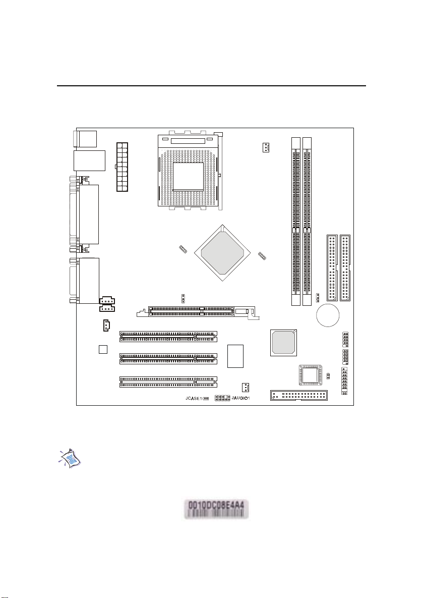
Mainboard Layout
Top : mouse
Bottom: keyboard
AUX1
CD1
ly
p
p
u
X
T
r S
A
e
w
o
P
PCI Slot 1
PCI Slot 2
PCI Slot 3
Top: LAN Jack
Bottom: USB
ports
Top : Parallel Port
Bottom:
COM A
VGA port
Top :
Game port
Bottom:
Line-Out
Line-In
Mic
JSPDIF1
Codec
SOCKET 462
SW2
AGP Slot
nVIDIA
CRUSH 11
Winbond
W83627HF-AW
CPUFAN1
SYSFAN1
nVIDIA
nFORCE
MCP-D
Introduction
JBAT1
3
2
M
M
BATT
IM
IM
+
D
D
JGS1
BIOS
1
2
E
E
ID
ID
J9
J10
FDD1
JFP1
MS-6367 Micro ATX Mainboard
Note: One unique MAC Address label is attached on PCI Slot 3 of the
motherboard that supports LAN. The label looks like the picture
below but its number varies depending on the board you purchased.
MAC Address Label
1-5
Page 6

Chapter 1
Quick Components Guide
Component Function Reference
SW2 CPU FSB Selection jumper See p. 2-4
JWR1 ATX 20-pin Power Connector See p. 2-7
JKBMS1 Mouse Connector See p. 2-8
JKBMS1 Keyboard Connector See p. 2-9
USB Connectors Connecting to USB devices See p. 2-9
COM A Connecting to Serial port See p. 2-10
VGA Connector Connecting to VGA port See p. 2-10
LPT1 Parallel port connector See p. 2-11
Game/Audio Connectors Connecting to Game/Audio devices See p. 2-12
RJ-45 LAN Jack Connecting to LAN devices See p. 2-12
FDD1 Floppy disk drive connector See p. 2-13
IDE1~ IDE2 Hard disk connectors See p. 2-14
JFP1 Case connectors See p. 2-15
CD1 CD-in connector See p. 2-17
AUX1 Aux line-in connector See p. 2-17
JGS1 Power Saving Switch Connector See p. 2-17
JCASE1 Chassis intrusion switch See p. 2-18
J9 & J10 Front USB connectors See p. 2-18
CPUFAN1/SYSFAN1 Fan power connectors See p. 2-19
JSPDIF1 SPDIF Connector See p. 2-20
JAUDIO1 Front panel audio connector See p. 2-21
JBAT1 Clear CMOS jumper See p. 2-22
AGP Slot Connecting to expansion cards See p. 2-23
PCI Slots Connecting to expansion cards See p. 2-23
1-6
Page 7

Chapter 2. Hardware Setup
Hardware Setup
Hardware Setup
This chapter provides you with the information about hardware setup
procedures. While doing the installation, be careful in holding the components
and follow the installation procedures. For some components, if you install in
the wrong orientation, the components will not work properly.
Use a grounded wrist strap before handling computer components. Static
electricity may damage the components.
TOPICS
Central Processing Unit: CPU 2-2
Memory 2-5
Power Supply 2-7
Back Panel 2-8
Connectors 2-13
Jumpers 2-22
Slots 2-23
2
2-1
Page 8

Chapter 2
Central Processing Unit: CPU
The mainboard supports AMD® Athlon and Duron processors.
It uses a CPU socket called Socket A for easy CPU installation. Make sure
the CPU has a Heat Sink and a cooling fan attached on the top to prevent
overheating. If you do not find the Heat Sink and cooling fan, contact your
dealer to purchase and install them before turning on the computer.
CPU Installation Procedures
1. Pull the lever sideways away
from the socket. Then, raise
the lever up to a 90-degree
angle.
2. Look for the cut edge. The
cut edge should point
towards the lever pivot. The
CPU will only fit in the
correct orientation.
Sliding
Plate
Cut edge
Open Lever
3. Press the CPU down firmly
into the socket and close the
lever. As the CPU is likely to
move while the lever is being
closed, always close the lever
with your finger pressing
tightly on top of the CPU to
make sure the CPU is properly
& completely embedded into
the socket.
Overheating will seriously damage the CPU and system,
always make sure the cooling fan can work properly to
WARNING!
protect the CPU from overheating.
2-2
Press down
the CPU
Close
Lever
Page 9

Hardware Setup
WARNING! Thermal Issue for CPU
As processor technology pushes to faster speeds and higher performance,
thermal management becomes increasingly crucial when building computer
systems. Maintaining the proper thermal environment is key to reliable
operation. As such, the processor must be maintained in the specified thermal
requirements.
AMD Athlon/Duron processor with a speed of 600MHz and above requires LARGER heatsink and fan. You also need to add thermal grease between the CPU and heatsink to improve heat dissipation. Then, make sure that
the CPU and heatsink are securely fastened and in good contact with each
other. These are needed to prevent damaging the processor and ensuring
reliable operation. If you want to get more information on the proper cooling,
you can visit AMDs website for reference.
2-3
Page 10

Chapter 2
CPU Core Speed Derivation Procedure
If CPU Clock = 100MHz
Core/Bus ratio = 7
then CPU core speed = Host Clock x Core/Bus ratio
= 100MHz x 7
= 700MHz
CPU FSB Selection Jumper: SW2
To use a 133MHz CPU, you need to set the SW2 jumper to short 1-2 pin.
To use a 100MHz CPU, set the SW2 jumper to short 2-3 pin.
1
SW2
WARNING!
3
1
FSB = 133MHz
FSB = 100MHz
3
1
Overclocking
This motherboard is designed to support overclocking.
However, please make sure your components are able to
tolerate such abnormal setting, while doing
overclocking. Any attempt to operate beyond product
specifications is not recommended. We do not guarantee
the damages or risks caused by inadequate operation or
beyond product specifications.
2-4
Page 11

Hardware Setup
Memory
Depending on the model you have purchased, the mainboard provides
2 sockets for 184-pin DDR DIMM (Double In-Line Memory Module) modules
and supports a maximum memory size of 1GB (2 DIMM slots). You can install
PC1600/PC2100 DDR SDRAM modules on the DDR DIMM slots (DIMM 1~2).
DDR DIMM Slots
(DIMM 1~2)
Introduction to DDR SDRAM
DDR (Double Data Rate) SDRAM is similar to conventional SDRAM,
but doubles the rate by transfering data twice per cycle. It transfers data on
both the rising and falling edges of the clock. Conventional SDRAM only
uses the rising edge of the clock to transfer data. Therefore, conventional
SDRAM is called SDR (Single Data Rate) SDRAM.
DDR SDRAM uses 2.5 volts as opposed to 3.3 volts used in SDR
SDRAM, and requires 184-pin DIMM modules rather than 168-pin DIMM
modules used by SDR SDRAM. DDR SDRAM is also known as SDRAM-II,
DDR DRAM and DSDRAM (Double-Speed DRAM).
Two types of DDR are available at the time of writing: PC1600 & PC2100.
PC1600 DDR SDRAM running at 100MHz will produce about 1.6GB/s memory
bandwidth. PC2100 running at 133MHz will produce 2.1GB/s memory
bandwidth. High memory bandwidth makes DDR an ideal solution for high
performance PC, workstations and servers.
2-5
Page 12

Chapter 2
DIMM Modules Combination
At least one DIMM module should be installed on the motherboard.
You can install memory modules in any combination as follows:
Slot Momory Module Total Memory
Slot 1 64MB, 128MB, 256MB, 64MB~512MB
(Bank 0 & 1) 512MB
Slot 2 64MB, 128MB, 256MB, 64MB~512MB
(Bank 2 & 3) 512MB
Maximum System Memory Supported 64MB~1GB
Warning: We dont recommend to install DOUBLE-SIDED
DDR266 module on DDR 3 slot because it will cause all memory
modules to slower down and run at 200MHz.
Installing DDR Modules
1. The DDR DIMM has only one notch on the center of module. The module
will only fit in the right orientation.
2. Insert the DIMM memory module vertically into the DIMM slot. Then
push it in until the golden finger on the memory module is deeply inserted
in the socket.
TIP: You can barely see the golden finger if the module is properly
inserted in the socket.
3. The plastic clip at each side of the DIMM slot will automatically close.
Volt
notch
2-6
Page 13

Hardware Setup
Power Supply
The mainboard supports ATX power supply for the power system.
Before inserting the power supply connector, always make sure that all components are installed properly to ensure that no damage will be caused.
ATX 20-Pin Power Supply
This connector allows you to connect to an ATX power supply. To
connect to the ATX power supply, make sure the plug of the power supply is
inserted in the proper orientation and the pins are aligned. Then push down
the power supply firmly into the connector.
11
1
20
10
ATX
Power Connector
PIN SIGNAL
1 3.3V
2 3.3V
3 GND
45V
5 GND
65V
7 GND
8 PW_OK
9 5V_SB
10 12V
PIN SIGNAL
11 3.3V
12 -12V
13 GND
14 PS_ON
15 GND
16 GND
17 GND
18 -5V
19 5 V
20 5 V
2-7
Page 14

Chapter 2
Back Panel
The Back Panel provides the following connectors:
Mouse
LAN
(optional)
Keyboard USB
COM A
Parallel
VGA
Midi/Joystick
L-out L-in MIC
Mouse Connector: JKBMS1
The mainboard provides a standard PS/2® mouse mini DIN connector for
attaching a PS/2® mouse. You can plug a PS/2® mouse directly into this
connector. The connector location and pin assignments are as follows:
Pin Definition
6
4
2
5
3
1
PS/2 Mouse (6-pin Female)
PIN SIGNAL DESCRIPTION
1 Mouse DATA Mouse DATA
2 N C No connection
3 G ND Ground
4 VCC +5V
5 Mouse Clock Mouse clock
6 N C No connection
2-8
Page 15

Hardware Setup
Keyboard Connector: JKBMS1
The mainboard provides a standard PS/2® keyboard mini DIN connector
for attaching a PS/2® keyboard. You can plug a PS/2® keyboard directly into
this connector.
Pin Definition
6
4
2
5
3
1
PS/2 Keyboard (6-pin Female)
PIN SIGNAL DESCRIPTION
1 Keyboard DATA Keyboard DATA
2 N C No connection
3 G ND Ground
4 VCC +5V
5 Keyboard Clock Keyboard clock
6 N C No connection
USB Connectors
The mainboard provides an OHCI (Open Host Controller Interface) Universal Serial Bus root for attaching USB devices such as keyboard, mouse or
other USB-compatible devices. You can plug the USB device directly into the
connector.
1 2 3 4
5 6 7 8
USB Ports
USB Port Description
PIN SIGNAL DESCRIPTION
1 VCC +5V
2 -Data 0 Negative Data Channel 0
3 +Data0 Positive Data Channel 0
4 G ND Ground
5 VCC +5V
6 -Data 1 Negative Data Channel 1
7 +Data 1 Positive Data Channel 1
8 G ND Ground
2-9
Page 16

Chapter 2
Serial Port Connector: COM A
The mainboard offers one 9-pin male DIN connector as serial port COM
A. The port is a 16550A high speed communication port that sends/receives 16
bytes FIFOs. You can attach a serial mouse or other serial devices directly to it.
Pin Definition
1 2 3 4 5
6 7 8 9
9-Pin Male DIN Connectors
PIN SIGNAL DESCRIPTION
1 DCD Data Carry Detect
2 SIN Serial In or Receive Data
3 SOUT Serial Out or Transmit Data
4 DTR Data Terminal Ready)
5 GN D Ground
6 DSR Data Set Ready
7 RTS Request To Send
8 CTS Clear To Send
9 RI Ring Indicate
VGA Connector
The mainboard provides a DB 15-pin female connector to connect a VGA
monitor.
51
15 11
VGA Connector
(DB 15-pin)
2-10
Pin Signal Description
1 RED
2 GREEN
3 BLUE
4 N/C
5 GND
6 GND
7 GND
8 GND
9 +5V
10 GND
11 N/C
12 SDA
13 Horizontal Sync
14 Vertical Sync
15 SCL
Page 17

Hardware Setup
Parallel Port Connector: LPT1
The mainboard provides a 25-pin female centronic connector for LPT. A
parallel port is a standard printer port that supports Enhanced Parallel Port
(EPP) and Extended Capabilities Parallel Port (ECP) mode.
13 1
25
14
Pin Definition
PIN SIGNAL DESCRIPTION
1 STROBE Strobe
2 DATA0 Data0
3 DATA1 Data1
4 DATA2 Data2
5 DATA3 Data3
6 DATA4 Data4
7 DATA5 Data5
8 DATA6 Data6
9 DATA7 Data7
10 ACK# Acknowledge
11 BUSY Busy
12 PE Paper End
13 SELECT Select
14 AUTO FEED# Automatic Feed
15 ERR# Error
16 INIT# Initialize Printer
17 SLIN# Select In
18 GND Ground
19 GND Ground
20 GND Ground
21 GND Ground
22 GND Ground
23 GND Ground
24 GND Ground
25 GND Ground
2-11
Page 18

Chapter 2
RJ-45 LAN Jack (optional)
The mainboard provides one standard RJ-45 jack for connection to Local
Area Network (LAN). You can connect a network cable to the LAN jack.
Pin Definition
PIN SIGNAL DESCRIPTION
1 TDP Transmit Differential Pair
2 TDN Transmit Differential Pair
RJ-45 LAN Jack
3 RD P Receive Differential Pair
4 N C Not Used
5 N C Not Used
6 R DN Receive Differential Pair
7 N C Not Used
8 N C Not Used
Joystick/Midi Connectors
You can connect a joystick or game pad to this connector.
Audio Port Connectors
Line Out is a connector for Speakers or Headphones. Line In is used for
external CD player, Tape player, or other audio devices. Mic is a connector for
microphones.
1/8 Stereo Audio Connectors
Line Out Line In MIC
2-12
Page 19

Hardware Setup
Connectors
The mainboard provides connectors to connect to FDD, IDE HDD,
case, USB Ports, IR module and CPU/System FAN.
Floppy Disk Drive Connector: FDD1
The mainboard provides a standard floppy disk drive connector that
supports 360K, 720K, 1.2M, 1.44M and 2.88M floppy disk types.
2
1
FDD1
34
33
2-13
Page 20

Chapter 2
Hard Disk Connectors: IDE1 & IDE2
The mainboard uses an IDE controller on the nVIDIA® MCP-D chipset
that provides PIO mode 0-4, Bus Master, and Ultra DMA 33/66/100 modes. It
has two HDD connectors IDE1 (Primary) and IDE2 (Secondary). You can
connect up to four hard disk drives, CD-ROM or 120MB Floppy to IDE1 and
IDE2.
IDE1 (Primary IDE Connector)
- The first hard disk drive should always be connected to IDE1. You can
connect a Master and a Slave drive to IDE1.
IDE2 (Secondary IDE Connector)
- You can connect a Master and a Slave drive to IDE2.
40 39
40 39
2
2
1
IDE1IDE2
If you install two hard disks on cable, you must configure the
second drive to Slave mode by setting its jumper. Refer to the
TIP
hard disk documentation supplied by hard disk vendors for
jumper setting instructions.
2-14
1
Page 21

Hardware Setup
Case Connector: JFP1
The case connector block JFP1 allows you to connect to the Power
Switch, Reset Switch, Keylock, Speaker, Power LED, and HDD LED on the
case.
Reset
Power Switch
Connect to a 2-pin push button switch.
Switch
Speaker
Buzzer
(short pin)
Keylock
JFP1
+
+
HDD LED
Power
Switch
Power
LED
Reset Switch
Reset switch is used to reboot the system rather than turning the power ON/
OFF. Avoid rebooting while the HDD is working. You can connect the
Reset switch from the system case to this pin.
Power LED
The Power LED is lit while the system power is on. Connect the Power LED
from the system case to this pin.
Speaker
Speaker from the system case is connected to this pin.
If on-board Buzzer is available, then:
2-15
Page 22

Chapter 2
Short pin 14-15: On-board Buzzer Enabled.
Open pin 14-15: On-board Buzzer Disabled
HDD LED
HDD LED shows the activity of a hard disk drive. Avoid turning the power
off while the HDD is working. You can connect the HDD LED from the
system case to this pin.
Keylock
Keylock allows you to disable the keyboard for security purpose. You can
connect the keylock to this pin.
2-16
Page 23

Hardware Setup
CD-In/Aux Line-In Connectors: CD1/AUX1
AUX1 is for DVD add-on card with Line-in connector.
CD1 is for CD-ROM audio connector.
GND
R
L
AUX1
GND
R
L
CD1
Power Saving Switch Connector: JGS1
Attach a power saving switch to this connector. Pressing the switch
once will have the system enter the sleep/suspend state. Press any key to
wake up the system.
2-17
JGS1
Page 24

Chapter 2
Chassis Intrusion Switch Connector: JCASE1
This connector is connected to a 2-pin chassis switch. If the chassis is
opened, the switch will be short. The system will record this status and show
a warning message on the screen. To clear the warning, you must enter the
BIOS utility and clear the record.
JCASE1
Front USB Connectors: J9 & J10
The mainboard provides two USB (Universal Serial Bus) pin headers,
that allow you to connect optional USB ports for front panel. These connectors are compliant with Intel Front Panel I/O Connectivity Design Guide.
2-18
1
1
9
9
J9
J10
2
2
10
10
J9/10 Pin Definition
PIN SIGNAL
1 USBPWR
2 USBPWR
3 USBP04 USBP15 USBP0+
6 USBP1+
7 GND
8 GND
9NC
10 USBOC
Page 25

Hardware Setup
Fan Power Connectors: CPUFAN1/SYSFAN1
The CPUFAN1 (processor fan) and SYSFAN1 (system fan) support
system cooling fan with +12V. It supports three-pin head connector. When
connecting the wire to the connectors, always take note that the red wire is
the positive and should be connected to the +12V, the black wire is Ground
and should be connected to GND. If the mainboard has a System Hardware
Monitor chipset on-board, you must use a specially designed fan with speed
sensor to take advantage of the CPU fan control.
SENSOR
+12V
GND
CPUFAN1
SENSOR
Note:
1. Always consult the vendor for proper CPU cooling fan.
2. CPU Fan supports the fan control.
2-19
+12V
GND
SYSFAN1
Page 26

Chapter 2
SPDIF Connector: JSPDIF1
The connector is used to connect SPDIF (Sony & Philips Digital Interconnect Format) interface for digital audio transmission.
1
3
JSPDIF1
JSPDIF1 Pin Definition
PIN SIGNAL
1 VCC
2 SPDIF
3 GND
Connected to JSPDIF1
SPDIF Bracket
2-20
Page 27

Hardware Setup
Front Panel Audio Connector: JAUDIO1
The front panel audio connector allows you to connect to the front panel
audio and is compliant with Intel Front Panel I/O Connectivity Design Guide.
10
2
JAUDIO1
1
Pin Definition
PIN SIGNAL DESCRIPTION
1 AUD_MIC Front panel microphone input signal
2 AUD_GND Ground used by analog audio circuits
3 AUD_MIC_BIAS Microphone power
4 AUD_VCC Filtered +5V used by analog audio circuits
5 AUD_FPOUT_R Right channel audio signal to front panel
6 AUD_RET_R Right channel audio signal return from front panel
7 HP_ON Reserved for future use to control headphone amplifier
8 KEY No pin
9 AUD_FPOUT_L Left channel audio signal to front panel
10 AUD_RET_L Left channel audio signal return from front panel
9
Note:
If you dont want to connect to the front audio
header, pins 5 & 6, 9 & 10 have to be jumpered
in order to have signal output directed to the
rear audio ports. Otherwise, the Line-Out connector on the back panel will not function.
2-21
10
6
9
5
Page 28

Chapter 2
Jumpers
The motherboard provides the following jumpers for you to set the
computers function. This section will explain how to change your
motherboards function through the use of jumpers.
Clear CMOS Jumper: JBAT1
There is a CMOS RAM on board that has a power supply from external
battery to keep the data of system configuration. With the CMOS RAM, the
system can automatically boot OS every time it is turned on. If you want to
clear the system configuration, use the JBAT1 (Clear CMOS Jumper ) to clear
data. Follow the instructions below to clear the data:
1
JBAT1
WARNING!
3
1
Clear Data
3
1
Keep Data
You can clear CMOS by shorting 2-3 pin while the
system is off. Then return to 1-2 pin position. Avoid
clearing the CMOS while the system is on; it will damage the mainboard.
2-22
Page 29

Hardware Setup
Slots
The motherboard provides one AGP slot and three 32-bit Master PCI
slots.
AGP Slot
PCI Slots
AGP (Accelerated Graphics Port) Slot
The AGP slot allows you to insert the AGP 1.5V graphics card. AGP is
an interface specification designed for the throughput demands of 3D graphics.
It introduces a 66MHz, 32-bit channel for the graphics controller to directly
access main memory and provides three levels of throughputs: 1x (266Mbps),
2x (533Mbps) and 4x (1.07Gbps).
The AGP slot only supports 4x 1.5V AGP card. Use of
WARNING
3.3V AGP card may cause damages to the mainboard.
PCI Slots
The PCI slots allow you to insert the expansion cards to meet your
needs. When adding or removing expansion cards, make sure that you unplug
the power supply first. Meanwhile, read the documentation for the expansion
card to make any necessary hardware or software settings for the expansion
card, such as jumpers, switches or BIOS configuration.
2-23
Page 30

Chapter 2
PCI Interrupt Request Routing
The IRQ, abbreviation of interrupt request line and pronounced I-R-Q,
are hardware lines over which devices can send interrupt signals to the
microprocessor.
The AGP/PCI IRQ pins are typically connected to the PCI bus INTA#INTE# pins as follows:
Order 1 Order 2 Order 3 Order 4
AGP INT E# INT A#
PCI Slot 1 INT A# INT B# INT C# INT D#
PCI Slot 2 INT B# INT C# INT D# INT A#
PCI Slot 3 INT C# INT D# INT A# INT B#
PCI Slot 1~3: Bus Master.
2-24
 Loading...