

Page 1
K8N Neo3 Series
MS-7135 (v1.X) ATX Mainboard
English/ French/ German Version
G52-M7135X3
i
Page 2
Manual Rev: 1.1
Release Date: Feb. 2005
FCC-B Radio Frequency Interference Statement
This equipment has been tested and found to comply with the limits for a class B
digital device, pursuant to part 15 of the FCC rules. These limits are designed to
provide reasonable protection against harmful interference when the equipment is
operated in a commercial environment. This equipment generates, uses and can
radiate radio frequency energy and, if not installed and used in accordance with the
instruction manual, may cause harmful interference to radio communications. Operation of this equipment in a residential area is likely to cause harmful interference, in
which case the user will be required to correct the interference at his own expense.
Notice 1
The changes or modifications not expressly approved by the party responsible for
compliance could void the user’s authority to operate the equipment.
Notice 2
Shielded interface cables and A.C. power cord, if any, must be used in order to
comply with the emission limits.
VOIR LA NOTICE D’INSTALLATION AVANT DE RACCORDER AU RESEAU.
Micro-Star International
MS-7135
This device complies with Part 15 of the FCC Rules. Operation is subject to the
following two conditions:
(1) this device may not cause harmful interference, and
(2) this device must accept any interference received, including interference that may
cause undesired operation.
ii
Page 3

Copyright Notice
The material in this document is the intellectual property of MICRO-STAR
INTERNATIONAL. We take every care in the preparation of this document, but no
guarantee is given as to the correctness of its contents. Our products are under
continual improvement and we reserve the right to make changes without notice.
Trademarks
All trademarks are the properties of their respective owners.
AMD, Athlon™, Athlon™ XP, Thoroughbred™, and Duron™ are registered
trademarks of AMD Corporation.
Intel® and Pentium® are registered trademarks of Intel Corporation.
PS/2 and OS®/2 are registered trademarks of International Business Machines
Corporation.
Microsoft is a registered trademark of Microsoft Corporation. Windows® 98/2000/NT/
XP are registered trademarks of Microsoft Corporation.
NVIDIA, the NVIDIA logo, DualNet, and nForce are registered trademarks or trademarks of NVIDIA Corporation in the United States and/or other countries.
Netware® is a registered trademark of Novell, Inc.
Award® is a registered trademark of Phoenix Technologies Ltd.
AMI® is a registered trademark of American Megatrends Inc.
Revision History
Revision Revision History Date
V1.1 First release for PCB 1.X Feb. 2005
European version
Technical Support
If a problem arises with your system and no solution can be obtained from the user’ s
manual, please contact your place of purchase or local distributor. Alternatively,
please try the following help resources for further guidance.
Visit the MSI website for FAQ, technical guide, BIOS updates, driver updates,
and other information: http://www.msi.com.tw/program/service/faq/
faq/esc_faq_list.php
Contact our technical staff at: support@msi.com.tw
iii
Page 4
Safety Instructions
1. Always read the safety instructions carefully.
2. Keep this User’s Manual for future reference.
3. Keep this equipment away from humidity.
4. Lay this equipment on a reliable flat surface before setting it up.
5. The openings on the enclosure are for air convection hence protects the equipment from overheating. DO NOT COVER THE OPENINGS.
6. Make sure the voltage of the power source and adjust properly 110/220V before connecting the equipment to the power inlet.
7. Place the power cord such a way that people can not step on it. Do not place
anything over the power cord.
8. Always Unplug the Power Cord before inserting any add-on card or module.
9. All cautions and warnings on the equipment should be noted.
10. Never pour any liquid into the opening that could damage or cause electrical
shock.
11. If any of the following situations arises, get the equipment checked by a service
personnel:
† The power cord or plug is damaged.
† Liquid has penetrated into the equipment.
† The equipment has been exposed to moisture.
† The equipment has not work well or you can not get it work according to
User’s Manual.
† The equipment has dropped and damaged.
† The equipment has obvious sign of breakage.
12. DO NOT LEAVE THIS EQUIPMENT IN AN ENVIRONMENT UNCONDITIONED, STORAGE TEMPERATURE ABOVE 600 C (1400F), IT MAY DAMAGE THE EQUIPMENT.
CAUTION: Danger of explosion if battery is incorrectly replaced.
Replace only with the same or equivalent type recommended by the
manufacturer.
iv
Page 5

CONTENTS
FCC-B Radio Frequency Interference Statement..........................................................ii
Copyright Notice...............................................................................................................iii
Trademarks......................................................................................................................iii
Revision History...............................................................................................................iii
Technical Support............................................................................................................iii
Safety Instructions.........................................................................................................iv
English........................................................................................................................E-1
Français......................................................................................................................F-1
Deutsch......................................................................................................................G-1
v
Page 6

Page 7

Quick User’s Guide
K8N Neo3 Series
(MS-7135 v1.X)
ATX Mainboard
English
E-1
Page 8

MS-7135 ATX Mainboard
E-2
Page 9
Quick User’s Guide
MS-7135 (v1.X)
Quick User’s Guide
Thank you for choosing the K8N Neo3 (MS-7135) v1.X ATX
mainboard. The K8N Neo3 mainboard is based on nVIDIA® nForce4-
4X chipset for optimal system efficiency. Designed to fit the advanced
AMD® K8 Athlon 64 processor, the K8N Neo3 mainboard delivers a
high performance and professional desktop platform solution.
MSI Reminds You...
Please note that the companion MSI Driver/Utility CD supports this
mainboard with Windows 2000/XP system drivers ONLY.
E-3
Page 10

MS-7135 ATX Mainboard
Mainboard Specifications
CPU
† Supports Socket-754 for AMD K8 Athlon 64 processor
† Supports up to 3700+ Athlon 64 processor or higher
(For the latest information about CPU, please visit http://www.msi.com.tw/program/products/mainboard/mbd/pro_mbd_cpu_support.php)
Chipset
† nVIDIA® nForce4-4X
- HyperTransport link to the AMD Athlon 64 CPU
- Supports single-channel DDR333/400 memory
- Supports PCI Express x16/x1 interface
- Two independent SATA controllers, for four drives
- Dual Ultra ATA 133/100/66 IDE controllers
- Supports high-speed USB2.0 ports
Main Memory
† Supports single-channel, four-memory-bank DDR 333/400 using two 184-pin DDR
DIMMs
† Supports a maximum memory size up to 2GB without ECC
† Supports 2.5v DDR SDRAM DIMM
(For the updated supporting memory modules, please visit http://www.msi.com.
tw/program/products/mainboard/mbd/pro_mbd_trp_list.php)
Slots
† One PCI Express x16 slot (PCI Express Bus specification v1.0a compliant)
† One PCI Express x1 slot (PCI Express Bus specification v1.0a compliant)
† Three 32-bit Master 3.3V/5V PCI Bus slots
† One AGR (Advance Graphics Riser) slot for compatible AGP VGA cards
(For more detailed information on compatible AGP VGA cards, please refer to
http://www.msi.com.tw/program/products/mainboard/mbd_index.php)
Onboard IDE
† Dual IDE controllers on the nVIDIA® nForce4-4X chipset provides IDE HDD/CD-
ROM with PIO, Bus Master and Ultra DMA 133/100/66 operation modes
† Can connect up to 4 IDE devices
Onboard Serial ATA
† Supports 4 SATA ports with up to 150MB/s transfer rate
MSI Reminds You...
To create a bootable RAID volume for a Windows 2000 environment,
Microsoft’s Windows 2000 Service Pack 4 (SP4) is required. As the
end user cannot boot without SP4, a combination installation CD must
be created before attempting to install the operating system onto the
bootable RAID volume.
E-4
Page 11

Quick User’s Guide
To create the combination installation CD, please refer to the following
website:
http://www.microsoft.com/windows2000/downloads/servicepacks/
sp4/HFdeploy.htm
USB Interface
† 10 USB ports
- Controlled by nForce4-4X chipset
- 4 ports in the rear I/O, 6 ports via the external bracket
NV RAID (Software)
† Supports up to 4 SATA and 4 ATA133 Hard drives
-RAID 0, 1, 0+1, or JBOD supported
-RAID function available for PATA133 + SATA H/D drives
LAN
† Marvell PHY 88E1111 Gigabit Ethernet chip (Optional)
† Realtek 8201 CL 10/100Mb/s Ethernet chip (Optional)
Audio
† RealTek ALC655 6-channel software audio codec
- Compliance with AC97 v2.3 spec.
- Meets PC2001 audio performance requirement
On-Board Peripherals
† On-Board Peripherals include:
- 1 floppy port supports 1 FDD with 360K, 720K, 1.2M, 1.44M and 2.88Mbytes
- 2 serial ports
- 1 parallel port supporting SPP/EPP/ECP mode
- 10 USB2.0 ports (Rear*4 / Front*6)
- 1 Audio (Line-In/Line-Out/MIC) port
- 1 RJ-45 LAN jack
- 1 CD-In pinheader
- 2 IDE ports support 4 IDE devices
- 4 serial ATA ports
BIOS
† The mainboard BIOS provides “Plug & Play” BIOS which detects the peripheral
devices and expansion cards of the board automatically.
† The mainboard provides a Desktop Management Interface (DMI) function which
records your mainboard specifications.
† Supports boot from LAN, USB Device 1.1 & 2.0, and SATA HDD.
Dimension
† ATX form factor: 300mm x 185mm
Mounting
† 6 mounting holes
E-5
Page 12
MS-7135 ATX Mainboard
SW_BAT1
FDD1
SATA1
SATA2
SATA3
SATA4
J1
MM
1
CFAN1
PCI 3
PCI 2
PCI 1
PCI_E1
PCI_E2
nVIDIA
nForce4-4X
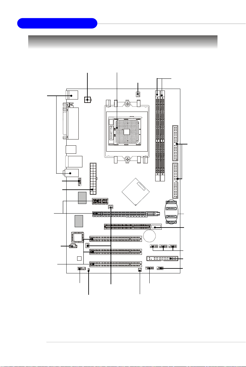
Quick Components Guide
Back Panel
I/O, p.E-13
JCOM1, p.E-16
JWR1, p.E-11
PCI Express
Slots, p.E-18
J1, p.E-14
PCI Slots, p.E-18
JPW1, p.E-11
Top: Mouse
Bottom: Keyboard
Top:
Parallel Port
Bottom:
COM Port
USB Ports
T: LAN Jack
B: USB Ports
Line-In
Line-Out
Mic
JCOM1
LAN
Winbond
W83627THF
S
O
I
B
Codec
JAUD1
JPW1
JWR1
SFAN1
JCI1
CPU, p.E-7
NBFAN1
AGR
CFAN1, p.E-15
T
T
A
B
JUSB1
JFP1
DDR DIMMs, p.E-10
2
E
IDE1/2, p.E-15
D
I
1
E
2
D
I
M
M
I
I
D
D
SATA1~4, p.E-14
AGR Slot, p.E-19
+
JUSB2
JUSB3
JUSB1/2/3, p.E-17
FDD1, p.E-14
JFP2
JFP2, p.E-16
E-6
JAUD1, p.E-16
JCI1, p.E-14
NBFAN1/
SFAN1, p.E-15
JFP1, p.E-16
SW_BAT1, p.E-17
Page 13
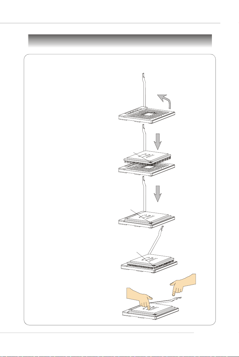
Central Processing Unit: CPU
Gold arrow
Gold arrow
Gold arrow
Correct CPU placement
Incorrect CPU placement
Close
Press down
CPU Installation Procedures for Socket 754
1.Please turn off the power and
unplug the power cord before
installing the CPU.
Quick User’s Guide
Open Lever
2.Pull the lever sideways away
from the socket. Make sure to
raise the lever up to a 90degree angle.
3.Look for the gold arrow on the
CPU. The gold arrow should
point as shown in the picture.
The CPU can only fit in the
correct orientation.
4.If the CPU is correctly installed,
the pins should be completely
embedded into the socket and
cannot be seen. Please note
that any violation of the correct
installation procedures may
cause permanent damages to
your mainboard.
5. Press the CPU down firmly into
the socket and close the lever.
As the CPU is likely to move
while the lever is being closed,
always close the lever with
your fingers pressing tightly on
top of the CPU to make sure
the CPU is properly and
completely embedded into the
socket.
Sliding
Plate
90 degree
O
X
the CPU
Lever
E-7
Page 14
MS-7135 ATX Mainboard
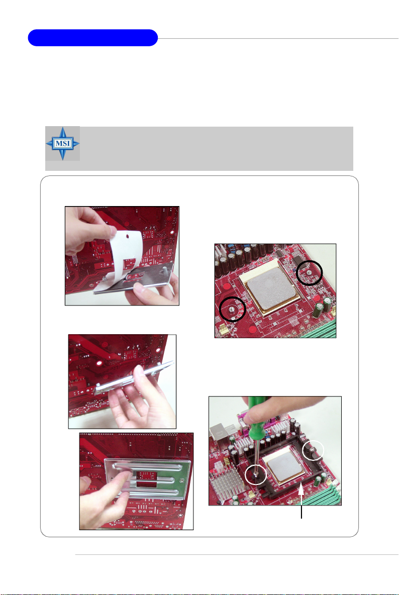
Installing AMD Athlon64 CPU Cooler Set
When you are installing the CPU, make sure the CPU has a heat sink
and a cooling fan attached on the top to prevent overheating. If you do not
have the heat sink and cooling fan, contact your dealer to purchase and install
them before turning on the computer.
MSI Reminds You...
Mainboard photos shown in this section are for demonstration of the
cooler installation for Socket 754 CPUs only. The appearance of
your mainboard may vary depending on the model you purchase.
1.Detach the shield off the
backplate’s paster.
2.Turn over the mainboard, and install
the backplate to the proper position.
3.Turn over the mainboard again, and
place the mainboard on the flat
surface. Locate the two screw
holes of the mainboard.
E-8
4.Align the retention mechanism and
the backplate.
Fix the retention mechanism and
the backplate with two screws.
retention mechanism
Page 15
Quick User’s Guide
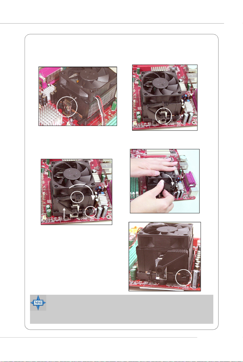
5.Position the cooling set onto the retention mechanism.
Hook one end of the clip to hook first, and then press down the other end of
the clip to fasten the cooling set on the top of the retention mechanism.
6.Locate the Fix Lever, Safety Hook
and the Fixed Bolt. Lift up the
intensive fixed lever.
Safety Hook
Fixed Lever
Fixed Bolt
8.Make sure the safety hook completely clasps the fixed bolt of the
retention mechanism.
9.Attach the CPU Fan cable to the
CPU fan connector on the
mainboard.
MSI Reminds You...
While disconnecting the Safety Hook from the fixed bolt, it is necessary to keep an eye on your fingers, because once the Safety Hook is
disconnected from the fixed bolt, the fixed lever will spring back instantly.
7.Fasten down the lever.
E-9
Page 16
MS-7135 ATX Mainboard
Memory
The mainboard provides 2 slots for 184-pin DDR DIMM (Double In-Line Memory
Module) modules and supports the memory size up to 2GB. You can install DDR 333/
400 modules on the DDR DIMM slots (DIMM 1~2).
Memory Population Rules
Install at least one DIMM module on the slots. Each DIMM slot supports up to a
maximum size of 1GB. Users can install either single- or double-sided modules to
meet their own needs.
Slot Memory Module Total Memory
DIMM 1 Single/Double Side 64MB~1GB
DIMM 2 Single/Double Side 64MB~1GB
Maximum System Memory Supported 64MB~2GB
MSI Reminds You...
1. Make sure that you install memory modules of the same type and
density on DDR DIMMs.
2. For systems using double-sided DDR400 modules in single-channel mode, the maximum DRAM speed is DDR333.
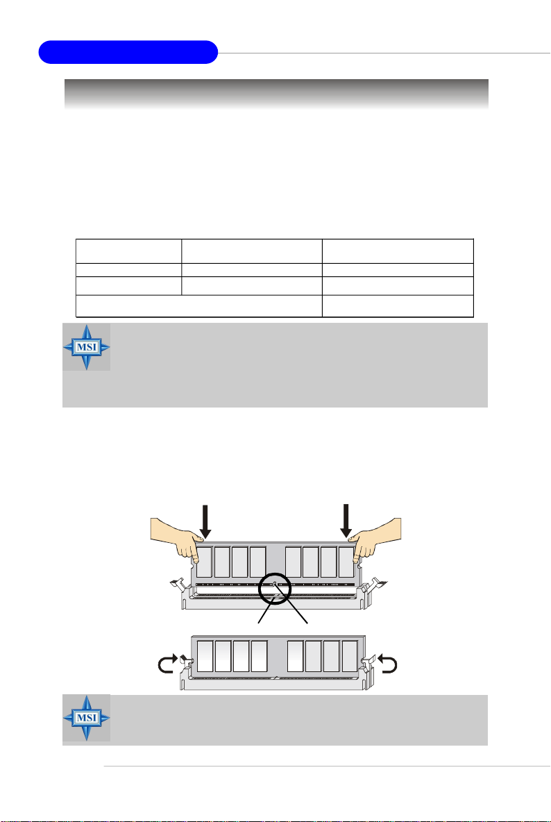
Installing DDR Modules
1. The DDR DIMM has only one notch on the center of module. The module will only
fit in the right orientation.
2. Insert the DIMM memory module vertically into the DIMM slot. Then push it in until
the golden finger on the memory module is deeply inserted in the socket.
3. The plastic clip at each side of the DIMM slot will automatically close.
E-10
Volt
MSI Reminds You...
You can barely see the golden finger if the module is properly
inserted into the socket.
Notch
Page 17
Quick User’s Guide
Power Supply
The mainboard supports ATX power supply for the power system. Before
inserting the power supply connector, always make sure that all components are
installed properly to ensure that no damage will be caused.
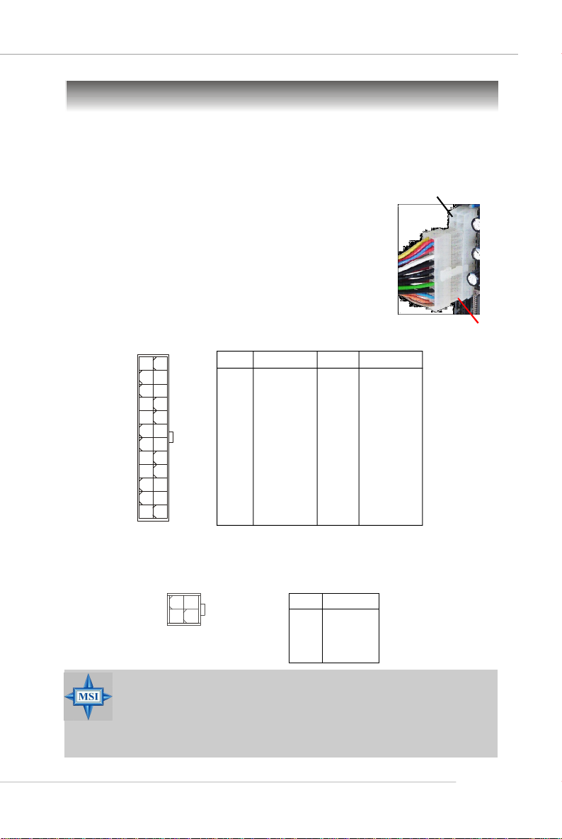
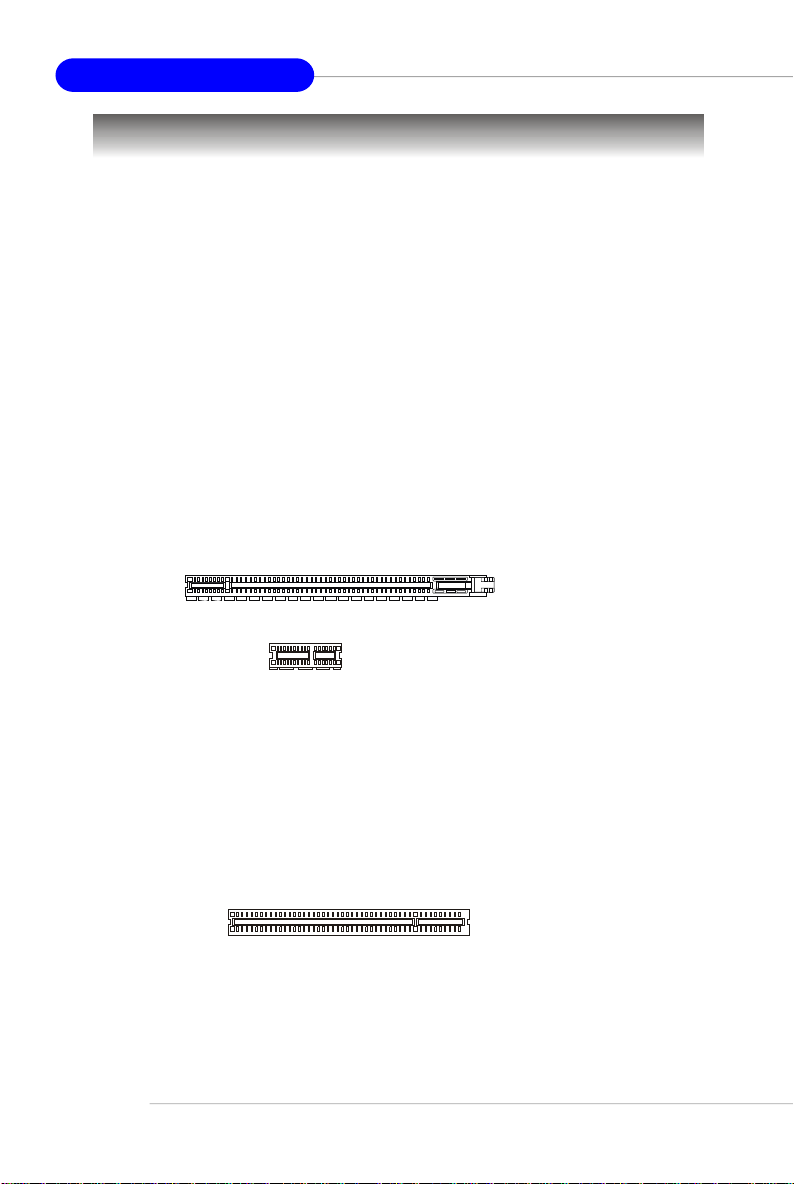
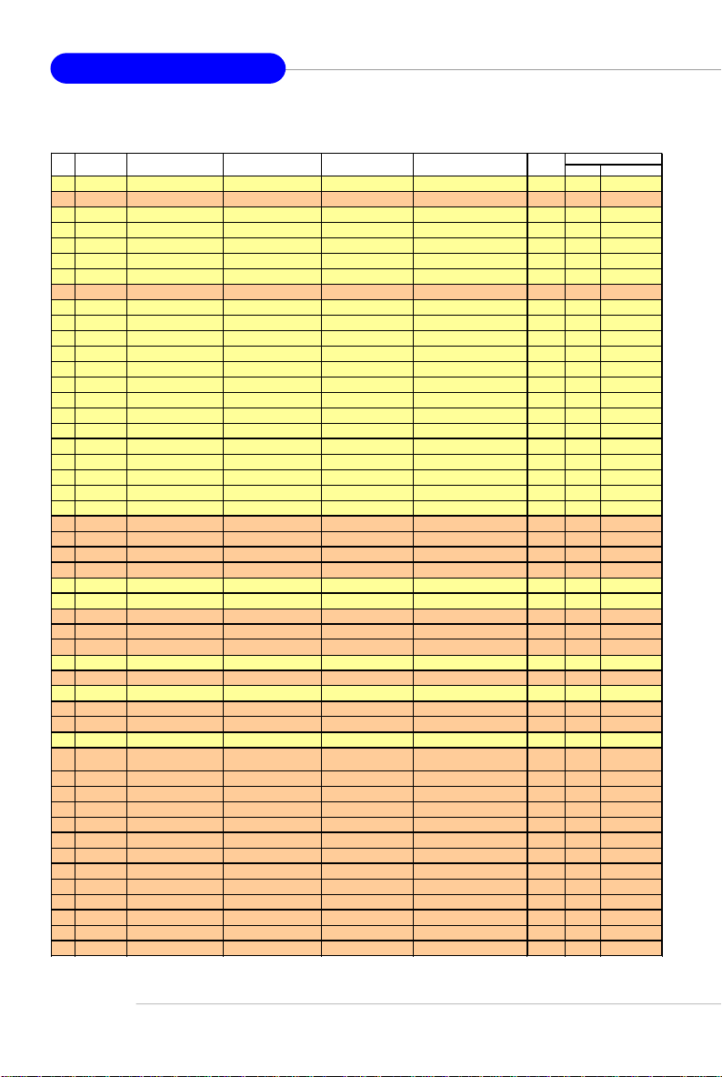
ATX 24-Pin Power Connector: JWR1
This connector allows you to connect an ATX 24-pin power
supply. To connect the ATX 24-pin power supply, make sure the
plug of the power supply is inserted in the proper orientation
and the pins are aligned. Then push down the power supply
firmly into the connector.
You may use the 20-pin ATX power supply as you like. If
you’d like to use the 20-pin ATX power supply, please plug your
power supply along with pin 1 & pin 13 (refer to the image at the
right hand). There is also a foolproof design on pin 11, 12, 23 &
24 to avoid wrong installation.
12 24
JWR1
1
13
PIN SIGNAL
1 +3.3V
2 +3.3V
3 GND
4 +5V
5 GND
6 +5V
7 GND
8 PWR OK
9 5VSB
10 +12V
11 +12V
12 NC
Pin Definition
PIN SIGNAL
13 +3.3V
14 -12V
15 GND
16 PS-ON#
17 GND
18 GND
19 GND
20 Res
21 +5V
22 +5V
23 +5V
24 GND
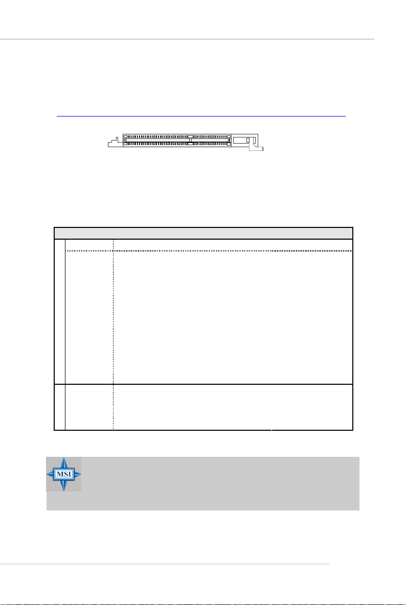
ATX 12V Power Connector: JPW1
This 12V power connector is used to provide power to the CPU.
JPW1 Pin Definition
1
2
JPW1
3
4
PIN SIGNAL
1 GND
2 GND
3 12V
4 12V
pin 12
pin 13
MSI Reminds You...
1. These two connectors connect to the ATX power supply and have to
work together to ensure stable operation of the mainboard.
2. Power supply of 350 watts (and above) is highly recommended for
system stability.
3. ATX 12V power connection should be greater than 18A.
E-11
Page 18
MS-7135 ATX Mainboard
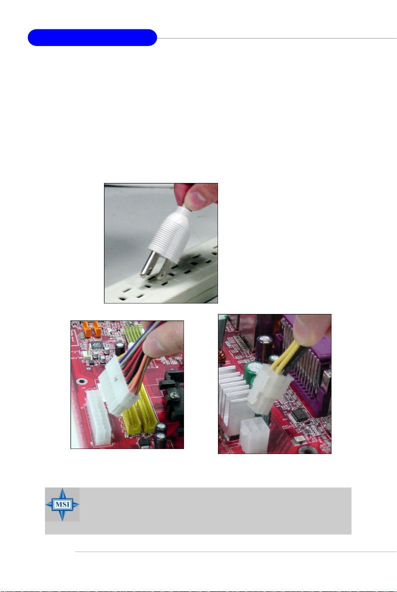
Important Notification about Power Issue
nVIDIA chipset is very sensitive to ESD (Electrostatic Discharge), therefore
this issue mostly happens while users intensively swap memory modules under S5
(power-off) states, and the power code is plugged while installing modules. Due to
several pins are very sensitive to ESD, so this kind of memory-replacement actions
might cause chipset system unable to boot. Please follow the following solution to
avoid this situation.
Unplug the AC power cable (shown in figure 1) or unplug the JWR1 & JPW1
power connectors (shown in figure 2 & figure 3) before the 1st installation or during
system upgrade procedure.
Figure 1:
Unplug the AC power cable
Unplug the JWR1 power connector
Figure 2:
MSI Reminds You...
Mainboard photos shown in this section are for demonstration only.
The appearance of your mainboard may vary depending on the model
you purchase.
E-12
Unplug the JPW1 power connector
Figure 3:
Page 19
Mouse
Back Panel
Parallel
Quick User’s Guide
L-In
LAN
Keyboard
Serial Port
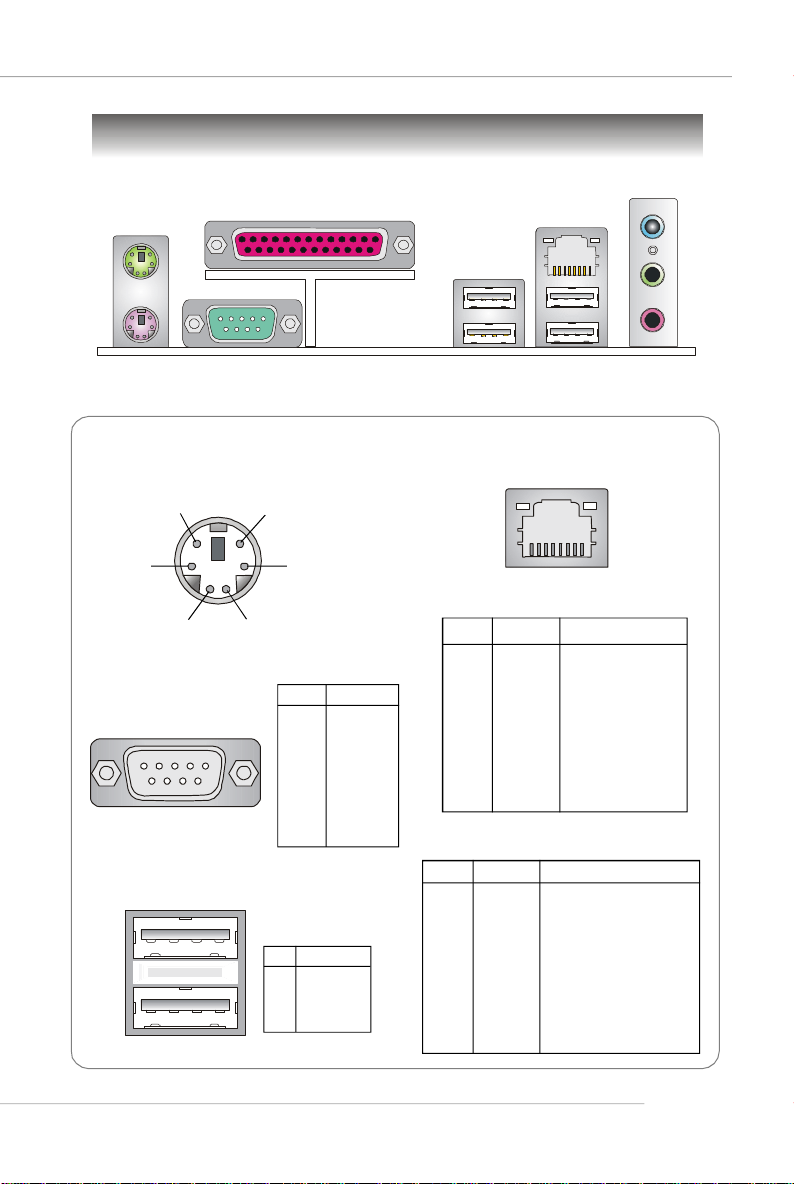
Mouse/Keyboard Connector
Pin5
Pin6 NC
Pin2 NC
Serial Port
1 2 3 4 5
6 7 8 9
Mouse/KBD Clock
Pin3 GNDPin4 VCC
Pin1
Mouse/KBD
DATA
PIN SIGNAL
1 DCD
2 SIN
3 SOUT
4 DTR
5 GND
6 DSR
7 RTS
8 CTS
9 RI
USB Ports
1 2 3 4
PIN SIGNAL
1 VCC
2 -Data
3 +Data
4 GND
USB Ports
RJ-45 LAN Jack
8 1
Gigabit LAN (Optional)
PIN SIGNAL DESCRIPTION
1 D0P Differential Pair 0+
2 D0N Differential Pair 03 D1P Differential Pair 1+
4 D2P Differential Pair 2+
5 D2N Differential Pair 26 D1N Differential Pair 17 D3P Differential Pair 3+
8 D3N Differential Pair 3-
10/100 LAN (Optional)
PIN SIGNAL DESCRIPTION
1 TDP Transmit Differential Pair
2 TDN Transmit Differential Pair
3 RDP Receive Differential Pair
4 NC Not Used
5 NC Not Used
6 RDN Receive Differential Pair
7 NC Not Used
8 NC Not Used
L-Out
Mic
E-13
Page 20
MS-7135 ATX Mainboard
Connectors
Floppy Disk Drive Connector: FDD1
The mainboard provides a standard floppy disk drive connector that supports
360K, 720K, 1.2M, 1.44M and 2.88M floppy disk types.
FDD1
CD-In Connector: J1
This connector is provided for CD-ROM audio.
Chassis Intrusion Switch Connector: JCI1
This connector is connected to a 2-pin chassis switch. If
the chassis is opened, the switch will be short. The system will
record this status and show a warning message on the screen.
To clear the warning, you must enter the BIOS utility and clear the
record.
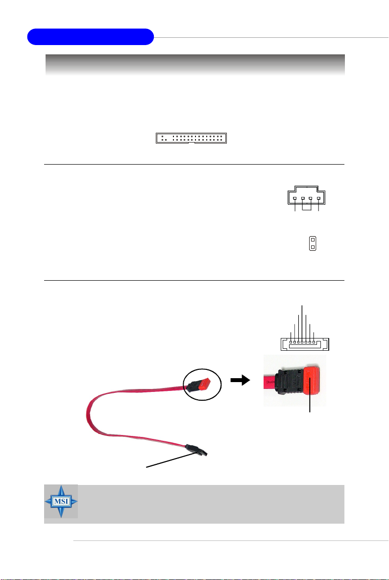
Serial ATA Connectors: SATA1~SATA4
SATA1~SATA4 are high-speed Serial ATA interface ports.
Each supports 1st generation serial ATA data rates of 150MB/s
and is fully compliant with Serial ATA 1.0 specifications. Each
Serial ATA connector can connect to 1 hard disk device.
Serial ATA cable
Take out the dust cover and
connect to the hard disk
devices
CINTRU
RXN
RXP
GND
R
GND
GND
J1
GND
JCI1
TXN
TXP
L
2
1
GND
E-14
Connect to SATA1/2/3/4
MSI Reminds You...
Please do not fold the Serial ATA cable into 90-degree angle. Otherwise,
data loss may occur during transmission.
Page 21
Quick User’s Guide
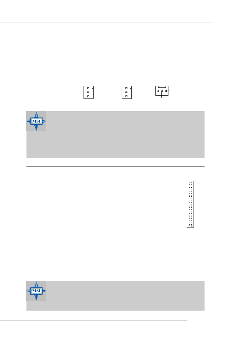
Fan Power Connectors: CFAN1 / SFAN1 / NBFAN1
The fan power connectors support system cooling fan with +12V. When
connecting the wire to the connectors, always note that the red wire is the positive
and should be connected to the +12V, the black wire is Ground and should be
connected to GND. If the mainboard has a System Hardware Monitor chipset onboard,
you must use a specially designed fan with speed sensor to take advantage of the
CPU fan control.
Sensor
+12V
GND
CFAN1
Sensor
+12V
GND
SFAN1
Sensor
GND
+12V
NBFAN1
MSI Reminds You...
1. Always consult the vendors for proper CPU cooling fan.
2. CFAN1 supports Smart Fan control. You can install Core Center
utility that will automatically control the CPU fan speed according
to the actual CPU temperature. Alternatively, you may set up the
smart fan control functions in the BIOS setup utility.
3. Please refer to the recommended CPU fans at AMD® official website.
ATA133 Hard Disk Connectors: IDE1 & IDE2
The mainboard has a 32-bit Enhanced PCI IDE and Ultra DMA 66/100/
133 controller that provides PIO mode 0~4, Bus Master, and Ultra DMA 66/
100/133 function. You can connect up to four hard disk drives, CD-ROM
and other IDE devices.
The Ultra ATA133 interface boosts data transfer rates between the
computer and the hard drive up to 133 megabytes (MB) per second. The
new interface is one-third faster than earlier record-breaking Ultra ATA/
100 technology and is backwards compatible with the existing Ultra ATA
interface.
IDE1 (Primary IDE Connector)
The first hard drive should always be connected to IDE1. IDE1 can connect a Master
and a Slave drive. You must configure second hard drive to Slave mode by setting the
jumper accordingly.
IDE2 (Secondary IDE Connector)
IDE2 can also connect a Master and a Slave drive.
MSI Reminds You...
If you install two hard disks on cable, you must configure the second
drive to Slave mode by setting its jumper. Refer to the hard disk documentation supplied by hard disk vendors for jumper setting instructions.
E-15
Page 22
MS-7135 ATX Mainboard
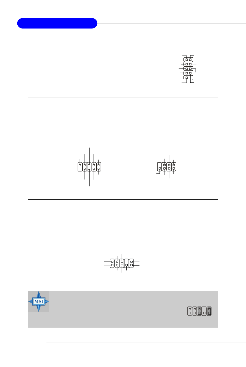
Serial Port Header: JCOM1
The mainboard offers one 9-pin header as serial port.
The port is a 16550A high speed communication port that
sends/receives 16 bytes FIFOs. You can attach a serial
mouse or other serial device directly to it.
Data Carry
Detect
Serial Out
GND
Request
To Send
Ring
Indicate
JCOM1
Serial In
Data
Terminal
Ready
Data Set
Ready
Clear
To Send
Front Panel Connectors: JFP1, JFP2
The mainboard provides two front panel connectors for electrical connection
to the front panel switches and LEDs. The JFP1 is compliant with Intel® Front Panel I/
O Connectivity Design Guide.
RST_SW_N
RST_SW_P
Reserved
JFP1
PWR_SW_N
HDD_LED_N
HDD_LED_P
FP PWR/SLP
FP PWR/SLP
PWR_SW_P
JFP2
SPK+
PLED
BUZ-
SLED
BUZ+
GND
SPK-
Front Panel Audio Connector: JAUD1
The JAUD1 front panel audio connector allows you to connect to the front
panel audio and is compliant with Intel® Front Panel I/O Connectivity Design Guide.
E-16
JAUD1
AUD_VCC
AUD_GND
AUD_MIC
AUD_MIC_BIAS
AUD_RET_R
2
1
AUD_FPOUT_R
10
AUD_RET_L
AUD_FPOUT_L
9
HP_ON
MSI Reminds You...
If you don’t want to connect to the front audio header, pins
5 & 6, 9 & 10 have to be jumpered in order to have signal
output directed to the rear audio ports. Otherwise, the
Line-Out connector on the back panel will not function.
6
10
5
9
Page 23
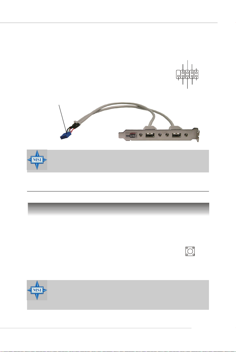
Front USB Connectors: JUSB1, JUSB2, JUSB3
The mainboard provides three standard USB 2.0
pin headers. USB 2.0 technology increases data
transfer rate up to a maximum throughput of 480Mbps,
which is 40 times faster than USB 1.1, and is ideal for
connecting high-speed USB interface peripherals such
as USB HDD, digital cameras, MP3 players,
printers, modems and the like.
Connect to JUSB1, JUSB2, or
JUSB3
MSI Reminds You...
Note that the pins of VCC and GND must be connected correctly to
avoid possible damage.
Quick User’s Guide
USB0+
USB0-
GND
VCC
JUSB1/2/3
USBOC
USB 2.0 Bracket
(Optional)
GND
USB1-
USB1+
VCC
Jumpers/Buttons
Clear CMOS Button: SW_BAT1
CMOS stands for Complementary Metal-Oxide Semiconductor and is more specifically referred to as CMOS RAM. It is a tiny 64-byte region of memory
that, owing to battery power, retains system configuration data when
the PC is shut off. With the CMOS RAM, the system can automatically
boot OS every time it is turned on. If you want to clear the system
configuration, press the SW_BAT1 button to have the data erased.
MSI Reminds You...
You can clear CMOS by pressing this button while the system is off.
Avoid clearing CMOS while the system is on; it will damage the
mainboard.
SW_BAT1
E-17
Page 24
MS-7135 ATX Mainboard
Slots
The motherboard provides one PCI Express x1 slot, one PCI Express x16 slot,
three 32-bit PCI slots, and one AGR slot.
PCI (Peripheral Component Interconnect) Express Slots
The PCI Express slots support high-bandwidth, low pin count, and serial
interconnect technology. You can insert the expansion cards to meet your needs.
When adding or removing expansion cards, make sure that you unplug the power
supply first.
PCI Express architecture provides a high performance I/O infrastructure for
Desktop Platforms with transfer rates starting at 2.5 Giga transfers per second over
a PCI Express x1 lane for Gigabit Ethernet, TV Tuners, 1394 controllers, and general
purpose I/O. Also, desktop platforms with PCI Express Architecture will be designed
to deliver highest performance in video, graphics, multimedia and other sophisticated
applications. Moreover, PCI Express architecture provides a high performance graphics
infrastructure for Desktop Platforms doubling the capability of existing AGP 8x designs with transfer rates of 4.0 GB/s over a PCI Express x16 lane for graphics
controllers, while PCI Express x1 supports transfer rate of 250 MB/s.
PCI Express x16 slot
PCI Express x1 slot
PCI (Peripheral Component Interconnect) Slots
The PCI slots allow you to insert the expansion cards to meet your needs.
When adding or removing expansion cards, make sure that you unplug the power
supply first. Meanwhile, read the documentation for the expansion card to make any
necessary hardware or software settings for the expansion card, such as jumpers,
switches or BIOS configuration.
PCI Slots
E-18
Page 25
Quick User’s Guide
AGR (Advance Graphics Riser) Slot
The AGR slot is a special design that only supports compatible AGP VGA
cards. For more detailed information on compatible AGP VGA cards, please refer
to http://www.msi.com.tw/program/products/mainboard/mbd_index.php .
AGR Slot
Compatible VGA Card List
System Configuration
Manufacturer Model No. Spec.
Processor AMD Athlon™ 64 Processor 2800+ FSB 200
Memory Transcend SEC K4H280838D-TCB3 DDR333 / 256MB
VGA Card As Follows
Lan Card Onboard
Sound Card Onboard
Hard Drive Hitachi HDS7222580VLSA80 SATA150 / 82.3GB
CD-ROM BenQ CD652A 52X
Floppy Drive TEAC FD-235HF 1.44MB
Power Supply DELTA DPS-300KB-1A 300W
Mouse Acer M-S69 PS/2
Keyboard Acer 6511-CX PS/2
Monitor ViewSonic P225f 22”CRT
Device Configuration
VGA BIOS
VGA Driver
MB Driver (from NVOM011 CD)
SW Info
MSI Reminds You...
The VGA BIOS and driver versions need to be identical to the versions in the compatibility list in order to have the AGR function work
properly.
E-19
Page 26
MS-7135 ATX Mainboard
MS-7135
VGA CARD
Vender
1 Alvatron FX5700U GeForce FX5700 Ultra 128MB/DDR SDRAM 4.36.20.18.01 8X Pass 6.14.10.6681
2 ATI Fire GL 8800 Fire GL 8800 128MB/SDRAM 1.03 4X Pass 6.14.10.6462
3 GAINWARD GFX 5900 Ultra GeForce 4 FX 5900 U 256MB/DDR SDRAM 4.35.20.24.00 8X Pass 6.14.10.6681
4 Gigabyte GV-R9200 Radeon 9200 128MB/DDR SDRAM BK-AMI 8.9 8X Pass 6.14.10.6430
5 Gigabyte GV-N57L128D GeForce FX5700LE 128MB/DDR SDRAM 4.36.20.30.00 8X Pass 6.14.10.6172
6 Leadtek Winfast A360LE TD GeForce FX5700LE 128MB/DDR SDRAM 4.36.20.30.00 8X Pass 6.14.10.6681
7 Leadtek Winfast A400GT TDH GeForce 6800GT 256MB/DDR SDRAM 5.40.02.15.00 8X Pass 6.14.10.6681
8 MSI MS-8863 GeForce 4 MX 460 64MB/SDRAM 4.17.00.30.06 4X Pass 6.14.10.6681
9 MSI MS-8907 GeForce FX 5200 64MB/DDR SDRAM 4.34.20.22.00 8X Pass 6.14.10.6681
10 MSI MS-8911 GeForce FX 5200 128MB/DDR SDRAM 4.34.20.15.00 8X Pass 6.14.10.6681
11 MSI MS-8919 GeForce FX 5200 128MB/DDR SDRAM 4.34.20.23.08 8X Pass 6.14.10.6681
12 MSI MS-8923 GeForce FX 5200 Ultra 128MB/DDR SDRAM 4.34.20.23.00 8X Pass 6.14.10.6681
13 MSI MS-8929 GeForce FX 5900 128MB/DDR SDRAM 4.35.20.18.04 8X Pass 6.14.10.6681
14 MSI MS-8931 GeForce FX 5600 Ultra 128MB/DDR SDRAM 4.31.20.51.00 8X Pass 6.14.10.6681
15 MSI MS-8936 GeForce4 MX4000 64MB/DDR SDRAM 4.18.20.42.00 8X Pass 6.14.10.6172
16 MSI MS-8936 GeForce FX5500 128MB/DDR SDRAM 4.34.20.66.03 8X Pass 6.14.10.6172
17 MSI MS-8946 GeForce FX 5950 Ultra 256MB/DDR SDRAM 4.35.20.32.16 8X Pass 6.14.10.6172
18 MSI MS-8959 GeForce FX5700LE 128MB/DDR SDRAM 4.36.20.30.10 8X Pass 6.14.10.6681
19 MSI MS-8975 Nvidia GeForce 6800 128MB/DDR SDRAM 5.40.02.12.01 8X Pass 6.14.10.6172
20 Unika FX5200 SP5208 GeForce FX5200 64MB/DDR SDRAM 4.34.20.42.00 8X Pass 6.14.10.6172
21 MSI MS-8952 ATI Radeon 9250 128MB/DDR SDRAM 008.017D.031.000 8X Pass 6.14.10.6476
22 Power ColorR92U-LC3 Radeon 9250 128MB/DDR SDRAM 008.017D.016.000 8X Pass 6.14.10.6476
23 Power ColorRV6DE-NB3 Radeon 7000 64MB/DDR SDRAM 008.004.008.000 4X Pass 6.14.10.6453
24 ATI Radeon LE Radeon LE DDR 32MB/DDR SGRAM P/N113-10604-100 4X Pass 6.13.10.6153
25 ATI Fire GL 8700 Fire GL 8700 64MB/DDR SDRAM 1.11 4X Pass 6.12.10.3051
26 ATI Radeon 9000 Pro Radeon DDR 64MB/DDR SDRAM BK8.0.0 4X Pass 6.14.10.6458
27 ATI Radeon 9500 Radeon 9500 64MB/DDR SDRAM 113.94210.100 8X Pass 6.14.10.6458
28 ATI Radeon 9700 Radeon 9700 128MB/DDR SDRAM 113.94206.101 8X Pass 6.14.10.6458
29 ASUS AGP-V7700 Deluxe GeForce 2 GTS 32MB/DDR SGRAM 2.15.01.13 4X Pass 2.9.5.8
30 ASUS V8440 GeForce 4 Ti 4400 128MB/SDRAM 4.25.0022 4X Pass 2.9.5.8
31 ASUS V8460 Ultra GeForce 4 Ti 4600 128MB/SDRAM 4.25.0019 4X Pass 6.6.8.1
32 Creative 3D Blaster 5 RX9700 ProRadeon 9700 128MB/SGRAM 113.94206.101 8X Pass 6.14.10.6458
33 ELSA Gladiac 517 SV GeForce 4 MX420 64MB/SDRAM 4.17.00.24.E1 4X Pass 2.9.5.8
34 ELSA Gladiac 528 Ultra GeForce 4 Ti 4200 128MB/DDR SDRAM 4.28.20.21.E0 8X Pass 6.6.8.1
35 GAINWARD GeForce 4 MX460 64MB/DDR 4.17.0030 4X Pass 2.9.5.8
36 GAINWARD GeForce 4 MX440T 64MB/SDRAM 4.17.00.30 4X Pass 2.9.5.8
37 GAINWARD GeForce 4 MX440 64MB/DDR SDRAM 4.18.2007 8X Pass 6.6.8.1
38 Leadtek Winfast
39 Leadtek Winfast A170 TH GeForce 4 MX 420 64MB/SDRAM 4.17.00.28 4X Pass 2.9.5.8
40 Leadtek Winfast A250 TD GeForce 4 4400 Ti 128MB/SDRAM 4.25.0022 4X Pass 6.6.8.1
41 MSI MS-8806 Nvidia RIVA TNT2 32MB/SDRAM 2.05.17.03.00 4X Pass 6.6.8.1
42 MSI MS-8831 GeForce GTS Pro 64MB/SDRAM 3.15.01.00.07 4X Pass 6.6.8.1
43 MSI MS-8847 GeForce 4 MX 440 64MB/DDR SDRAM 4.17.0045 4X Pass 6.6.8.1
44 MSI MS-8851 GeForce 3 Ti 200 64MB/SDRAM 3.20.00.18.11 4X Pass 2.9.5.8
45 MSI MS-8852 GeForce 2 MX 100/200 32MB/SDRAM 3.11.0148 4X Pass 2.9.5.8
46 MSI MS-8860 GeForce 4 MX 440 64MB/SDRAM 4.17.00.24.52 4X Pass 2.9.5.8
47 MSI MS-8861 GeForce 4 MX 440 64MB/SDRAM 4.17.00.24.46 4X Pass 2.9.5.8
48 MSI MS-8870 GForce 4 Ti 4200 64MB/DDR SDRAM 4.25.00.29.10 4X Pass 2.9.5.8
49 MSI MS-8872 GeForce 4 Ti 4600 128MB/DDR SDRAM 4.25.00.27.33 4X Pass 2.9.5.8
50 MSI MS-8879 GeForce 4 Ti 4200 64MB/DDR SDRAM 4.25.0032 4X Pass 2.9.5.8
Model name VGA Chip
GeForce3 Titanium 500
TD
VGA Memory
64MB/SDRAM V11.05.2001 4X Pass 6.6.8.1
VGA BIOSNo.
AGP
SPEED
Result Driver Ver.
E-20
Page 27

Quick User’s Guide
VGA CARD
No.
Vender
51MSI MS-8888 GeForce 4 MX 440 64MB/DDR SDRAM 4.18.20.03.00 8X Pass 6.6.8.1
52MSI MS-8889 GeForce 4 Ti 4200 128MB/DDR SDRAM 4.28.20.05.02 8X Pass 6.6.8.1
53MSI MS-8890 GeForce 4 MX 440 64MB/DDR SDRAM 4.18.20.07.23 8X Pass 6.6.8.1
54MSI MS-8891 GeForce 4 MX 440 128MB/DDR SDRAM 4.18.20.02.21 8X Pass 6.6.8.1
55MSI MS-8894 GeForce 4 Ti 4200 128MB/DDR SDRAM 4.28.20.05.11 8X Pass 6.6.8.1
56MSI MS-8895 GeForce 4 MX 440 64MB/DDR SDRAM 4.18.2007 8X Pass 6.6.8.1
57MSI MS-8900 GeForce 4 Ti 4800 SE 128MB/DDR SDRAM 4.28.20.21.00 8X Pass 6.6.8.1
58MSI MS-8904 GeForce FX 5800 128MB/DDR SDRAM 4.30.20.23.05 8X Pass 6.6.8.1
59MSI MS-8948 GeForce FX 5700 128MB/DDR SDRAM 4.36.20.19.06 8X Pass 6.6.8.1
60NS GF4 MX440 GeForce 4 MX 440 64MB/DDR SDRAM 4.17.00.45.78 4X Pass 2.9.5.8
61Pixel View MVGA-NBG25GA GeForce 4 Ti 4200 128MB/SDRAM 4.25.00.28 4X Pass 2.9.5.8
62Triplex Xabre Pro 64MB/SDRAM 0.80.00 8X Pass 6.13.10.3080
63Triplex Millennium Silver GeForce 4 MX 440 64MB/DDR 4.17.00.24 4X Pass 2.9.5.8
64Triplex SIS Sabre 600 Ultra 64MB/DDR SDRAM 1.08.03 8X Pass 6.13.10.3080
65VINIX VINIX VX-3340 XABRE400 64MB/DDR SDRAM 1.03.01 8X Pass 6.13.10.3080
Model name VGA Chip
VGA Memory VGA BIOS
AGP
SPEED
MS-7135
Result Driver Ver.
PCI Interrupt Request Routing
The IRQ, acronym of interrupt request line and pronounced I-R-Q, are hardware lines over which devices can send interrupt signals to the microprocessor. The
PCI IRQ pins are typically connected to the PCI bus INT A# ~ INT D# pins as follows:
Order 1 Order 2 Order 3 Order 4
AGR Slot INT A# INT B#
PCI Slot 1 INT B# INT C# INT D# INT A#
PCI Slot 2 INT C# INT D# INT A# INT B#
PCI Slot 3 INT D# INT A# INT B# INT C#
E-21
Page 28

MS-7135 ATX Mainboard
Restore the previous CMOS value from CMOS, only for
BIOS Setup
Power on the computer and the system will start POST (Power On Self Test)
process. When the message below appears on the screen, press <DEL> key to
enter Setup.
Press DEL to enter SETUP
If the message disappears before you respond and you still wish to enter
Setup, restart the system by turning it OFF and On or pressing the RESET button. You
may also restart the system by simultaneously pressing <Ctrl>, <Alt>, and <Delete>
keys.
Control Keys
<↑>
<↓>
<←>
<→>
<Enter> Select the item
<Esc> Jumps to the Exit menu or returns to the main menu
<+/PU> Increase the numeric value or make changes
<-/PD> Decrease the numeric value or make changes
<F1> General help, only for Status Page Setup Menu and
<F5>
<F7> Load Optimized defaults
<F10> Save all the CMOS changes and exit
MSI Reminds You...
The items under each BIOS category described in this section are
under continuous update for better system performance. Therefore,
the description may be slightly different from the latest BIOS and
should be held for reference only.
Move to the previous item
Move to the next item
Move to the item in the left hand
Move to the item in the right hand
from a submenu
Option Page Setup Menu
Option Page Setup Menu
E-22
Page 29

Quick User’s Guide
The Main Menu
Standard CMOS Features
Use this menu for basic system configurations, such as time, date etc.
Advanced BIOS Features
Use this menu to setup the items of special enhanced features.
Advanced Chipset Features
Use this menu to change the values in the chipset registers and optimize your system’s
performance.
Integrated Peripherals
Use this menu to specify your settings for integrated peripherals.
Power Management Setup
Use this menu to specify your settings for power management.
PNP/PCI Configurations
This entry appears if your system supports PnP/PCI.
H/W Monitor
This entry shows your PC health status.
Cell Menu
Use this menu to specify your settings for CPU/AGP frequency/voltage control and
overclocking.
Load Optimized Defaults
Use this menu to load the default values set by the mainboard manufacturer specifically for optimal performance of the mainboard.
BIOS Setting Password
Use this menu to set the password for BIOS.
E-23
Page 30

MS-7135 ATX Mainboard
Cell Menu
Current CPU / DDR Clock
These two items show the current clocks of CPU & DDR. Read-only.
High Performance Mode
This field allows you to select the DDR timing setting. Setting to [Optimized] enables
relevant overclocking settings automatically to be determined by SPD. Selecting [Manual]
allows users to configure these fields manually. Setting options: [Optimized], [Manual].
Aggressive timing
This item allows you to enable or disable the memory clock. When [Enabled] is selected,
the timing delay of memory will be shorten to increase the performance. Setting
options: [Enabled], [Disabled].
Dynamic Overclocking
Dynamic Overclocking Technology is the automatic overclocking function, included in
the MSITM’s newly developed CoreCell
balance of CPU while running programs, and to adjust the best CPU frequency
automatically. When the motherboard detects CPU is running programs, it will speed
up CPU automatically to make the program run smoothly and faster. When the CPU is
temporarily suspending or staying in the low load balance, it will restore the default
settings instead. Usually the Dynamic Overclocking Technology will be powered only
when users' PC need to run huge amount of data like 3D games or the video process,
and the CPU frequency need to be boosted up to enhance the overall performance.
Setting options:
[Disabled] Disable Dynamic Overclocking function.
[Private] 1st level of overclocking, increasing the CPU frequency by 1%.
[Sergeant] 2nd level of overclocking, increasing the CPU frequency by 3%.
[Captain] 3rd level of overclocking, increasing the CPU frequency by 5%.
[Colonel] 4th level of overclocking, increasing the CPU frequency by 7%.
TM
Technology. It is designed to detect the load
E-24
Page 31

Quick User’s Guide
[General] 5th level of overclocking, increasing the CPU frequency by 9%.
[Commander] 6th level of overclocking, increasing the CPU frequency by 11%.
MSI Reminds You...
1. Even though the Dynamic Overclocking Technology is more stable
than manual overclocking, basically, it is still risky. We suggest
that users should make sure that the CPU can afford to overclocking
regularly first. If you find the PC appears to be unstable or reboot
incidentally, it's better to disable the Dynamic Overclocking or to
lower the level of overclocking options. By the way, if you need to
conduct overclocking manually, you also need to disable the Dy-
namic Overclocking first.
2. When overclocking, it is NOT recommended to use SATA devices.
Adjust CPU FSB Frequency
This item allows you to select the CPU Front Side Bus clock frequency (in MHz).
Select the number between [200]~[400] for needed frequency.
HT Frequency
This setting specifies the maximum operating frequency of the link’s transmitter clock.
Setting options: [1x], [1.5x], [2x], [2.5x], [3x], [4x], [5x].
HT Width
This field allows you to set the HT Width between CPU & Chip.↑ mark means Chip to
CPU HT Width. And ↓ mark means CPU to Chip HT Width. Setting options: [ ↓ 8 ↑ 8],
[ ↓ 16 ↑ 8], [↓ 8 ↑16], [ ↓16 ↑16].
CPU Spread Spectrum
This setting is used to enable or disable the CPU Spread Spectrum feature. When
overclocking the CPU, always set it to [Disabled]. Setting options: [Center Spread],
[Disabled].
SATA Spread Spectrum
This setting is used to enable or disable the SATA Spread Spectrum feature. Setting
options: [Disabled], [Down Spread].
PCIE Spread Spectrum
This setting is used to enable or disable the CPU Spread Spectrum feature. When
overclocking the CPU, always set it to [Disabled]. Setting options: [Disabled], [Down
Spread].
PCIE Clock
This setting determines the clock frequency of the PCI Express slots. Setting options:
[100MHz] ~ [145MHz].
SSE/SSE2 Instructions
This setting disables/enables the SSE/SSE2 Instructions. The Streaming SIMD Extensions (SSE) were introduced in the Pentium III processor. The SSE extensions con-
E-25
Page 32

MS-7135 ATX Mainboard
sist of a new set of instructions and a new set of registers. These instructions and
registers are designed to allow Single-Instruction Multiple-Data (SIMD) computations
to be made on single-precision floating-point numbers.
The Streaming SIMD Extensions 2 (SSE2) were introduced in the Pentium 4 and Intel
Xeon processors. They consist of a new set of instructions that operate on the XXM
and MXCSR registers and perform SIMD operations on double-precision floatingpoint values and on integer values.Several of these new SSE/SSE2 instructions also
operate in the MMX registers.
Cool ’n’ Quiet
This feature is especially designed for AMD Athlon processor, which provides a CPU
temperature detecting function to prevent your CPU’s from overheating due to heavy
workload. Setting options: [Disabled], [Enabled].
MSI Reminds You...
To ensure the stability of Cool'n'Quiet function, it is always recommended to have the memories plugged in DIMM1.
Adjust CPU Ratio
This item lets you adjust the CPU ratio. Setting to [Startup] enables the CPU running at
the fastest speed which is detected by system. Setting options are: [Startup], [x4]~
[x12].
Adjust CPU VID
This item lets you adjust the CPU VID. Setting to [Startup] enables the CPU running at
the default VID detected by the system. Setting options: [Startup], [1.550V] ~ [0.
825V].
Memory Voltage
Adjusting the DDR voltage can increase the DDR speed. Any changes made to this
setting may cause a stability issue, so changing the DDR voltage for long-term
purpose is NOT recommended.
NF4 Voltage
NF4 voltage is adjustable in this field.
MSI Reminds You...
The settings shown in different color in Memory Voltage and NF4
Voltage help to verify if your setting is proper for your system.
Gray: Default setting.
Yellow:High performance setting.
Red: Not recommended setting and the system may be
Changing CPU Voltage, Memory Voltage and NF4 Voltage may
result in the instability of the system; therefore, it is NOT recommended to change the default setting for long-term usage.
unstable.
E-26
Page 33

Manuel d’Utilisation
K8N Neo3 Series
(MS-7135 v1.X)
Carte Mère ATX
Français
F-1
Page 34

Carte Mère ATX MS-7135
F-2
Page 35

Manuel d’Utilisation
MS-7135 (v1.X)
Manuel d’Utilisation
Féliciation vous venez d’acheter une carte mèreATX K8N Neo3
(MS-7135) v1.X. La K8N Neo3 est basée sur le chipset n VIDIA
nForce4-4X offrant des performances importantes. Elle fonctionne
avec les processeurs AMD® K8 Athlon 64 et offre un système
hautment performant tant pour les particuliers que pour les
professionnels.
MSI Vous Rappelle...
Le CD d’installation MSI Driver/Utility ne supporte que les cartes
mère fonctionnant avec Windows 2000/XP.
®
F-3
Page 36

Carte Mère ATX MS-7135
Spécificités de la Carte
CPU
† Processeurs AMD Socket-754 K8 Athlon 64
† Processeur Athlon 64 jusqu’à 3700+ ou supérieur
(Pour une mise à jour sur les dernières informations relatives au cPU, veuillez
visiter :http://www.msi.com.tw/program/products/mainboard/mbd/
pro_mbd_cpu_support.php)
Chipset
† nVIDIA® nForce4-4X
- Lien HyperTransport avec le CPU AMD Athlon 64
- Supporte la mémoir een seul canal DDR333/400
- Supporte l’interface PCI Express x16/x1
- Deux contrôleurs indépendants SATA pour quatre disques
- Contrôleurs IDE Dual Ultra ATA 133/100/66
- Supporte l’USB2.0
Mémoire Principale
† Supporte le mode seul canal, quatre banques de mémoire DDR 333/400 (184
broches)
† Supporte un maximum de mémoire de 2GB non ECC
† Supporte 2.5v DDR SDRAM DIMM
(Pour une mise à jour sur les dernières informations relatives aux modules de
mémoire, veuillez visiter : http://www.msi.com.tw/program/products/mainboard/
mbd/pro_mbd_trp_list.php)
Slots
† Un PCI Express x16 slot (PCI Express Bus compatible avec les spec. v1.0a)
† Un PCI Express x1 slot (PCI Express Bus compatible avec les spec. v1.0a)
† Trois slots 32-bit Master 3.3V/5V PCI Bus
† Un slot AGR (Advance Graphics Riser) pour les cartes VGA compatibles AGR
(Pour plus d’information sur les cartes VGA compatibles AGP, veuillez visiter :
http://www.msi.com.tw/program/products/mainboard/mbd_index.php)
IDE Intégré
† Double contrôleur IDE dans le chipset nVIDIA® nForce4-4X qui procure IDE HDD/
CD-ROM avec PIO, Bus Master et les modes opératoires Ultra DMA 133/100/66
† Possibilité de connecter jusqu’à 4 matériels IDE
Serial ATA Intégré
† Supporte jusqu’ą 4 ports SATA avec un taux de transfert de 150MB/s
MSI Vous Rappelle...
Pour créer un disque de boot RAID pour Windows 2000, Service Pack
4 (SP4) Microsoft Windows 2000 est nécessaire. Vous ne pouvez
booter sans le SP4, il vous faut donc un CD d’instalation avant de
lancer l’installation du systčme d’exploitation.
F-4
Page 37

Manuel d’Utilisation
Pour créer ce CD, veuillez vous reporter à cette adresse :
http://www.microsoft.com/windows2000/downloads/servicepacks/
sp4/HFdeploy.htm
Interface USB
† 10 ports USB
- Controllé par le chipset nForce4-4X
- 4 ports à l’arrière, 6 ports via bracket externe
NV RAID (Logiciel)
† Supporte jusqu’à 4 disques SATA et 4 PATA133
-RAID 0, 1, 0+1, or JBOD supporté
-Fonction RAID disponible pour disques PATA133 + SATA H/D
LAN
† Puce Marvell PHY 88E1111 Gigabit Ethernet (Optionnel)
† Puce Realtek 8201 CL 10/100Mb/s Ethernet (Optionnel)
Audio
† Codec audio RealTek ALC655 6 canaux
- Compatible avec les spec. AC97 v2.3
- Répond aux exigences audio PC2001
Périph ériques Intégrés
† Les périphériques intégrés sont :
- 1 port floppy supportant 1 FDD avec 360K, 720K, 1.2M, 1.44M et 2.88Mbytes
- 2 ports série
- 1 port parallčle supportant les modes SPP/EPP/ECP
- 10 ports USB2.0 (Arrière *4 / Façade *6)
- 1 port audio (Line-In/Line-Out/MIC)
- 1 RJ-45 LAN jack
- 1 jeu de broches CD-In
- 2 ports IDE supportant 4 matériels IDE
- 4 ports serial ATA
BIOS
† La carte procure un BIOS “Plug & Play” qui détecté les périphériques et les cartes
d’extensions automatiquement.
† Cette carte fournie une fonction DMI (Desktop Management Interface) qui enregistre
les spécificités de la carte.
† Supporte le boot à partir du réseau, matériels USB 1.1 & 2.0, ainsi que le SATA
HDD.
Dimension
† Format ATX : 300mm x 185mm
Montage
† 6 trous de montage
F-5
Page 38

Carte Mère ATX MS-7135
SW_BAT1
FDD1
SATA1
SATA2
SATA3
SATA4
J1
MM
1
CFAN1
PCI 3
PCI 2
PCI 1
PCI_E1
PCI_E2
nVIDIA
nForce4-4X
Guide des Composants
Back Panel
I/O, p.F-13
JCOM1, p.F-16
JWR1, p.F-11
Slots PCI
Express, p.F-
18
J1, p.F-14
Slots PCI, p.F-18
JPW1, p.F-11
Top: Mouse
Bottom: Keyboard
Top:
Parallel Port
Bottom:
COM Port
USB Ports
T: LAN Jack
B: USB Ports
Line-In
Line-Out
Mic
JCOM1
LAN
Winbond
W83627THF
S
O
I
B
Codec
JAUD1
JPW1
JWR1
SFAN1
JCI1
CPU, p.F-7
NBFAN1
AGR
CFAN1, p.F-15
T
T
A
B
JUSB1
JFP1
DDR DIMMs, p.F-10
2
E
IDE1/2, p.F-15
D
I
1
E
2
D
I
M
M
I
I
D
D
SATA1~4, p.F-14
Slot AGR, p.F-19
+
JUSB2
JUSB3
JUSB1/2/3, p.F-17
FDD1, p.F-14
JFP2
JFP2, p.F-16
F-6
JAUD1, p.F-16
JCI1, p.F-14
NBFAN1/
SFAN1, p.F-15
JFP1, p.F-16
SW_BAT1, p.F-17
Page 39

Manuel d’Utilisation
Gold arrow
Gold arrow
Gold arrow
Correct CPU placement
Incorrect CPU placement
Close
Press down
Central Processing Unit: CPU
Procédures d’installation du CPU pour Socket 754
1. Veuillez éteindre et débrancher
votr e PC avant l’installation du
CPU.
Open Lever
2. Tirez le levier vers le haut.
Assurez-vous que celui-ci est
bien en position ouverte
maximum (angle de 90°).
3.Repérez la flèche dorée. La
flèche dorée doit se trouver
comme indiqué sur le dessin.
Le CPU ne peut être installer
que dans un seul sens.
4.Si le CPU est correctement
installé alors les broches ne
sont plus visibles. Une
mauvaise installation pourrait
entraîner des dommages vis-à-
vis de la carte mère
5. Appuyez sur le CPU pendant
que vous abaissez le levier. Il
faut toujours exercer une
pression sur le CPU pour éviter
que ce dernier ne soit pas bien
fixé une fois le levier abaissé.
Sliding
Plate
90 degree
O
X
the CPU
Lever
F-7
Page 40

Carte Mère ATX MS-7135
Installation du CPU AMD Athlon64
Quand vous installez votre CPU, assurez-vous que le CPU possède un
système de refroidissement pour prévenir les surchauffes.
MSI Vous Rappelle...
Les images ci-dessous servent de démonstration pour l’installation
de votre ventilateur pour Socket 754 CPUs uniquement. L’apparence
de votre carte mère peut varier selon les modèles.
1.Détacher la protection.
3.Retourner la carte mère et localiser
les deux trous de vis sur la carte
mère.
2.Retourner la carte mère et installer la
plaque métallique.
F-8
4.Aligner le méchanisme de rétention
et la plaque métallique.
Fixer le méchanisme de rétention et
la plaque métallique avec les vis.
méchanisme de
rétention
Page 41

Manuel d’Utilisation
5. Positionner le ventilateur sur le méchanisme de rétention.
Attacher un coté puis l’autre en s’assurant que l’ensemble est bien sécuris é.
6.Localiser le levier de fixation et le
crochet de sécurité. Relever le
levier.
Safety Hook
Fixed Lever
Fixed Bolt
8.S’assurer que le crochet est
sécurisé ( avec le méchanisme de
rétention).
9.Connectez le câble d’alimentation
sur le connecteur de la carte mère
prévu à cet effet
MSI Vous Rapelle...
Lorsque vous déconnectez le crochet, il est nécessaire de garder un
oeil sur vos doigts car une fois le crochet déconnecté, celui-ci reprend
sa position initial du à son ressort.
7.Abaisser le levier
F-9
Page 42

Carte Mère ATX MS-7135
Mémoire
La carte mère procure 2 slots DDR DIMM (Double In-Line Memory Module) (184
broches) et supporte jusqu’à 2GB de mémoire. Vous pouvez installer les modules
DDR 333/400 sur les slots DDR DIMM (DIMM 1~2).
Memory Population Rules
Installez au moins un module DIMM sur les slots. Chaque slot DIMM supporte
une taille maximum d’ 1GB. Vous pouvez installer des modules simples ou doubles
faces selon vos besoins
Slot Module de Mémoire Mémoire Totale
DIMM 1 Simple/Double Face 64MB~1GB
DIMM 2 Simple/Double Face 64MB~1GB
Système de mémoire maximum support ée 64MB~2GB
MSI Vous Rappelle...
1. Assurez-vus que vous installez des modules de mémoire de même
type et de même densité sur les DDR DIMMs.
2. Pour des systèmes utilisant des modules DDR400 Double Face en
mode seul canal, la vitesse maximum de la DRAM est DDR333.
Installation des modules DDR
1. La DDR DIMM ne posséde qu’une encoche en son centre. Le module ne peut être
monté que dans le bon sens
2. Insérez le module de mémoire DIMM verticalement sur le slot. Puis appuyez dessus
3. Le clip en plastique situé de chaque coté du module va se fermer automatiquement
F-10
Volt
MSI Vous Rappelle...
La marque dorée doit ą peine źtre visible lorsque le module est
correctement installé.
Encoche
Page 43

Manuel d’Utilisation
Alimentation
La carte mère supporte les alimentations ATX. Avant de brancher le connecteur
d’alimentation, il faut toujours vous assurer que tous les composants sont bien installés
afin de ne pas les endommager.
Connecteur d’alimentation ATX 24 broches: JWR1
Ce connecteur vous permet de connecter l’alimentation
ATX. Pour ce faire assurez vous que le connecteur est bein
positionné dans le bon sens. Puis appuyez sur le câble.
Vous pouvez aussi utiliser une alimentatin 20 broches.
Le détrompeur permettra de ne pas connecter l’alimentation sur
les broches 11, 12, 23 & 24.
Pin Definition
JWR1
12 24
1
PIN SIGNAL
1 +3.3V
2 +3.3V
3 GND
4 +5V
5 GND
6 +5V
7 GND
8 PWR OK
9 5VSB
10 +12V
13
11 +12V
12 NC
PIN SIGNAL
13 +3.3V
14 -12V
15 GND
16 PS-ON#
17 GND
18 GND
19 GND
20 Res
21 +5V
22 +5V
23 +5V
24 GND
Connecteur d’Alimentation ATX 12V : JPW1
Ce connecteur d’alimentation 12V permet l’alimentation du CPU.
JPW1 Pin Definition
1
2
JPW1
3
4
PIN SIGNAL
1 GND
2 GND
3 12V
4 12V
pin 12
pin 13
MSI Vous Rappelle...
1. Ce deux connecteurs ATX doivent fonctionner ensemble pour assurer la stabilité de la carte mère.
2. Une alimentation de 350Watt (et plus) est fortement recommandé
pour la stabilité du système.
3. La connexion ATX 12V doit être supérieure à 18A.
F-11
Page 44

Carte Mère ATX MS-7135
Information Importante sur l’alimentation
Le chipset NForce est très sensible à l’ESD (Décharge Eléctrostatique). Ce
problème intevient la plupart du temps lorsque l’utilisateur change des modules de
mémoire lorsque le pc est en veille (S5) et que l’alimentation est toujours connectée.
Etant donné que les broches des modulmes de mémoire sont sensibles aux (ESD) le
remplacement de la mémoire dans ces conditions peut endomager le chipset et
l’empecher de booter correctement. Veuillez suivre les indications ci-dessous :
Débrancher le câble d’alimentation (voir fig. 1) ou débrancher les connecteurs
JWR1 & JPW1 (voir fig. 2 & 3) avant la première installation ou une mise à jour de votre
matériel.
Figure 1:
Unplug the AC power cable
Unplug the JWR1 power connector
Figure 2:
MSI Vous Rappelle...
Les images ci-dessous servent de démonstration uniquement.
L’apparence de votre carte mère peut varier selon les modèles.
F-12
Unplug the JPW1 power connector
Figure 3:
Page 45

Souris
Panneau Arričre
Parallèle
Manuel d’Utilisation
L-In
LAN
Clavier
Port de série
Souris/Clavier
Pin6 NC
Pin2 NC
Port de série
1 2 3 4 5
6 7 8 9
Ports USB
1 2 3 4
Pin5
Mouse/KBD Clock
Pin3 GNDPin4 VCC
Pin1
Mouse/KBD
DATA
PIN SIGNAL
1 DCD
2 SIN
3 SOUT
4 DTR
5 GND
6 DSR
7 RTS
8 CTS
9 RI
PIN SIGNAL
1 VCC
2 -Data
3 +Data
4 GND
Ports USB
RJ-45 LAN
8 1
Gigabit LAN (Optionnel)
PIN SIGNAL DESCRIPTION
1 D0P Differential Pair 0+
2 D0N Differential Pair 03 D1P Differential Pair 1+
4 D2P Differential Pair 2+
5 D2N Differential Pair 26 D1N Differential Pair 17 D3P Differential Pair 3+
8 D3N Differential Pair 3-
10/100 LAN (Optionnel)
PIN SIGNAL DESCRIPTION
1 TDP Transmit Differential Pair
2 TDN Transmit Differential Pair
3 RDP Receive Differential Pair
4 NC Not Used
5 NC Not Used
6 RDN Receive Differential Pair
7 NC Not Used
8 NC Not Used
L-Out
Mic
F-13
Page 46

Carte Mère ATX MS-7135
Connecteurs
Connecteur Floppy Disk : FDD1
La carte est pourvue d’un connecteur de disquette qui supporte les disques de 360K,
720K, 1.2M, 1.44M et 2.88M.
FDD1
Connecteur CD-In : J1
Le connecteur est destiné au branchement audio du CD-ROM.
Connecteur Chassis Intrusion Switch: JCI1
Ce connecteur est connecté à deux broches chassis switch.
Si le chassis est ouvert le système enregistrera le statut. Pour
effacer le message, vous devez entrer dans les paramè tres du
BIOS et effacer ce dernier.
Connecteur Serial ATA : SATA1~SATA4
SATA1~SATA4 sont des ports d’interface Serial ATA
haute vitesse. Chacun supporte la 1e génération de Serial ATA
(taux de transfert 150MB/s) et est totalement compatible avec
les specificités Serial ATA 1.0 . Chaque connecteur peut être
connecté à un disque dur.
Serial ATA cable
Retirer le bouchon avant la
connection
CINTRU
RXN
RXP
GND
GND
GND
J1
R
GND
JCI1
TXN
TXP
L
2
1
GND
F-14
Connect to SATA1/2/3/4
MSI Vous Rappelle...
Ne pas tordre les câble serial ata avec un angle de 90° cela pourraît
gêner la transmission des données
Page 47

Manuel d’Utilisation
Connecteurs d’Alimentation Ventilateurs: CFAN1 / SFAN1 / NBFAN1
Ces connecteurs supportent le +12V. En connectant le câble au connecteur,
souvenez vous que le fil rouge est positif et doit être connecté au +12V, le fil noir
est la masse et doit être connecté à GND. Cette carte mère à un système de
surveillance matériel intégré, vous devez donc utilsier un ventillateur avec des
capteur de vitesse pour utiliser cette fonction de surveillance.
Sensor
+12V
GND
CFAN1
Sensor
+12V
GND
SFAN1
Sensor
GND
+12V
NBFAN1
MSI Vous Rappelle...
1. Toujours consulter votre revendeur au sujet du radiateur + ventilateur.
2. Vous pouvez installer l’utilitaire PC Alert pour contrôler la
température du CPU et la vitesse de rotation du ventilateur.
3. Veuillez vous rendre sur le site d’AMD® pour connaître les ventilateur
dont vous avez besoin.
Connecteurs Disque Dur : IDE1 & IDE2
La carte mère offre un contrôleur 32-bit Enhanced PCI IDE et Ultra
DMA 33/66/100/133 qui procure le PIO mode 0~4, Bus Master, et les
fonctions Ultra DMA 33/66/100/133. Vosu pouvez connecter jusqu’à
quatre disques durs, CD-ROM ou d’autres matériels.
L’interface Ultra ATA133 boosts le taux de transfert de données
entre le PC et le disque dur jusqu’à 133 megabytes (MB) par seconde. La
nouvelle interface est un tiers plus rapide que l’ancienne technologie Ultra
ATA/100 et est compatible avec l’interface Ultra ATA existente
IDE1 (Connecteur IDE Primaire)
Le premier disque dur doit oujours être relié à l’IDE1. Vous pouvez connecter un
disque en “maître” et un autre en “esclave” sur l’IDE1.
IDE2 (Connecteur IDE Secondaire)
Possibilité de connecter un disque en “maître” et un autre en “esclave” sur l’IDE2
MSI Vous Rappelle...
Si vous installez 2 disques durs sur une même nappe, vous devez
configurer le second disque en mode Slave (esclave) en bougeant un
cavalier. Pour cela il faut vous reporter à la documentation du disque
dur concerant le changement de cavaliers (jumpers).
F-15
Page 48

Carte Mère ATX MS-7135
Connecteur Port de Série : JCOM1
La carte mère offre un connecteur port de série 9
broches. C’est un port de communication haute vitesse
16550A qui envoie/reçoit 16 bytes FIFOs. Vous pouvez
attacher une souris ou autre composants de série
directement.
Data Carry
Detect
Serial Out
GND
Request
To Send
Ring
Indicate
JCOM1
Serial In
Data
Terminal
Ready
Data Set
Ready
Clear
To Send
Connecteurs Front Panel: JFP1, JFP2
La carte offre deux connecteurs front panel permettant l’alimentation electrique
de LED. JFP1 est compatible avec l’Intel® Front Panel I/O Connectivity Design Guide
RST_SW_N
RST_SW_P
Reserved
JFP1
PWR_SW_N
HDD_LED_N
HDD_LED_P
FP PWR/SLP
FP PWR/SLP
PWR_SW_P
JFP2
SPK+
PLED
BUZ-
SLED
BUZ+
GND
SPK-
Connecteur Audio Front Panel : JAUD1
Le connecteur JAUD1 front panel audio permet la connexion du front panel
audio et est compatible avec l’Intel® Front Panel I/O Connectivity Design Guide.
F-16
JAUD1
AUD_VCC
AUD_GND
AUD_MIC
AUD_MIC_BIAS
AUD_RET_R
2
1
AUD_FPOUT_R
10
AUD_RET_L
AUD_FPOUT_L
9
HP_ON
MSI Vous Rappelle...
Si vous ne voulez pas connecter le front audio header, les
broches 5 & 6, 9 & 10 doit être recouvertes avec un
cavalierpour que le signal de sortie soit redirigé sur les
ports audio de l’arrière. Dans le cas contraire, le connecteur
Line-Out sur le panneau arrière ne fonctionnera pas.
6 10
5
9
Page 49

Manuel d’Utilisation
Connecteurs Front USB: JUSB1, JUSB2, JUSB3
La carte offre trois USB 2.0 standards .La
technologie USB 2.0 permet d’augmenter le taux de
transfert jusqu’à 480Mbps, ce qui est 40 fois plus
rapide que l’USB 1.1, il est par conséquent idéal pour
les imprimantes, appraiels photos numériques, modems
etc..
Connect to JUSB1, JUSB2, or
JUSB3
MSI Vous Rappelle...
A Noter que les broches VCC et GND doivent être correctement
connecter. afin d’éviter tout endommagement.
JUSB1/2/3
USB0+
USB0-
GND
VCC
USBOC
GND
USB1-
USB1+
VCC
USB 2.0 Bracket
(Optionnel)
Cavaliers
Cavalier Clear CMOS : SW_BAT1
Le CMOS ressemble plus à une RAM étant donné qu’il est équipé d’un semi
conducteur. C’est une toute petite région de mémoire (64-byte),
possédant une batterie, qui retient les données de configuration du
système quand le PC est éteint. Avec la CMOS RAM, le système peut
automatiquement booter à chaque fois que le PC est allumé. Si vous
voulez effacer la configuration du système, utiliser le SW_BAT1 pour
effacer les données
MSI Vous Rappelle...
Vous pouvez effacer le CMOS en appuyant sur le bouton quand le PC
est éteint.
SW_BAT1
F-17
Page 50

Carte Mère ATX MS-7135
Slots
La carte mère procure un slot PCI Express x1, un slot PCI Express x16, trois
slots PCI 32-bit, et un slot AGR.
Slots PCI (Peripheral Component Interconnect) Express
Les slots PCI Express possèdent une large bande passante, supportent les
plateformes desktop AMD haute performances utilisant le processeur AMD ainsi que
les avantages de cette plateforme. L’architecture PCI Express procure une infra-
structure performante pour le graphique et double la capacité de l’AGP 8X avec un
taux de transfert de données de 4.0 GB/s sur un PCI Express x16 pour contrôleur
graphique alors que le PCI Express x 1 supporte un taux de transfert de 250 MB/s.
PCI Express x16 slot
PCI Express x1 slot
PCI (Peripheral Component Interconnect) Slots
Vous pouvez insérer des cartes d’expansion selon vos besoins. Lorsque
vous ajoutez ou enlever une carte d’expansion, assurez-vous que le PC n’est pas
relié au secteur.
PCI Slots
F-18
Page 51

Manuel d’Utilisation
Slot AGR (Advance Graphics Riser)
Le slot AGR est spécialement conçu pour supporter les cartes graphiques
AGP. Pour des informations sur la compatibilité des cartes graphiques, merci de
visiter : http://www.msi.com.tw/program/products/mainboard/mbd_index.
php.
AGR Slot
Liste de compatibilité des cartes graphiques
System Configuration
Manufacturer Model No. Spec.
Processor AMD Athlon™ 64 Processor 2800+ FSB 200
Memory Transcend SEC K4H280838D-TCB3 DDR333 / 256MB
VGA Card As Follows
Lan Card Onboard
Sound Card Onboard
Hard Drive Hitachi HDS7222580VLSA80 SATA150 / 82.3GB
CD-ROM BenQ CD652A 52X
Floppy Drive TEAC FD-235HF 1.44MB
Power Supply DELTA DPS-300KB-1A 300W
Mouse Acer M-S69 PS/2
Keyboard Acer 6511-CX PS/2
Monitor ViewSonic P225f 22”CRT
Device Configuration
VGA BIOS
VGA Driver
MB Driver (from NVOM011 CD)
SW Info
MSI Vous Rappelle...
Les versions des BIOS et des pilotes doivent être identiques aux
versions de la liste de compatibilité pour que la fonction AGR marche
correctement.
F-19
Page 52

Carte Mère ATX MS-7135
MS-7135
VGA CARD
Vender
1 Alvatron FX5700U GeForce FX5700 Ultra 128MB/DDR SDRAM 4.36.20.18.01 8X Pass 6.14.10.6681
2 ATI Fire GL 8800 Fire GL 8800 128MB/SDRAM 1.03 4X Pass 6.14.10.6462
3 GAINWARD GFX 5900 Ultra GeForce 4 FX 5900 U 256MB/DDR SDRAM 4.35.20.24.00 8X Pass 6.14.10.6681
4 Gigabyte GV-R9200 Radeon 9200 128MB/DDR SDRAM BK-AMI 8.9 8X Pass 6.14.10.6430
5 Gigabyte GV-N57L128D GeForce FX5700LE 128MB/DDR SDRAM 4.36.20.30.00 8X Pass 6.14.10.6172
6 Leadtek Winfast A360LE TD GeForce FX5700LE 128MB/DDR SDRAM 4.36.20.30.00 8X Pass 6.14.10.6681
7 Leadtek Winfast A400GT TDH GeForce 6800GT 256MB/DDR SDRAM 5.40.02.15.00 8X Pass 6.14.10.6681
8 MSI MS-8863 GeForce 4 MX 460 64MB/SDRAM 4.17.00.30.06 4X Pass 6.14.10.6681
9 MSI MS-8907 GeForce FX 5200 64MB/DDR SDRAM 4.34.20.22.00 8X Pass 6.14.10.6681
10 MSI MS-8911 GeForce FX 5200 128MB/DDR SDRAM 4.34.20.15.00 8X Pass 6.14.10.6681
11 MSI MS-8919 GeForce FX 5200 128MB/DDR SDRAM 4.34.20.23.08 8X Pass 6.14.10.6681
12 MSI MS-8923 GeForce FX 5200 Ultra 128MB/DDR SDRAM 4.34.20.23.00 8X Pass 6.14.10.6681
13 MSI MS-8929 GeForce FX 5900 128MB/DDR SDRAM 4.35.20.18.04 8X Pass 6.14.10.6681
14 MSI MS-8931 GeForce FX 5600 Ultra 128MB/DDR SDRAM 4.31.20.51.00 8X Pass 6.14.10.6681
15 MSI MS-8936 GeForce4 MX4000 64MB/DDR SDRAM 4.18.20.42.00 8X Pass 6.14.10.6172
16 MSI MS-8936 GeForce FX5500 128MB/DDR SDRAM 4.34.20.66.03 8X Pass 6.14.10.6172
17 MSI MS-8946 GeForce FX 5950 Ultra 256MB/DDR SDRAM 4.35.20.32.16 8X Pass 6.14.10.6172
18 MSI MS-8959 GeForce FX5700LE 128MB/DDR SDRAM 4.36.20.30.10 8X Pass 6.14.10.6681
19 MSI MS-8975 Nvidia GeForce 6800 128MB/DDR SDRAM 5.40.02.12.01 8X Pass 6.14.10.6172
20 Unika FX5200 SP5208 GeForce FX5200 64MB/DDR SDRAM 4.34.20.42.00 8X Pass 6.14.10.6172
21 MSI MS-8952 ATI Radeon 9250 128MB/DDR SDRAM 008.017D.031.000 8X Pass 6.14.10.6476
22 Power ColorR92U-LC3 Radeon 9250 128MB/DDR SDRAM 008.017D.016.000 8X Pass 6.14.10.6476
23 Power ColorRV6DE-NB3 Radeon 7000 64MB/DDR SDRAM 008.004.008.000 4X Pass 6.14.10.6453
24 ATI Radeon LE Radeon LE DDR 32MB/DDR SGRAM P/N113-10604-100 4X Pass 6.13.10.6153
25 ATI Fire GL 8700 Fire GL 8700 64MB/DDR SDRAM 1.11 4X Pass 6.12.10.3051
26 ATI Radeon 9000 Pro Radeon DDR 64MB/DDR SDRAM BK8.0.0 4X Pass 6.14.10.6458
27 ATI Radeon 9500 Radeon 9500 64MB/DDR SDRAM 113.94210.100 8X Pass 6.14.10.6458
28 ATI Radeon 9700 Radeon 9700 128MB/DDR SDRAM 113.94206.101 8X Pass 6.14.10.6458
29 ASUS AGP-V7700 Deluxe GeForce 2 GTS 32MB/DDR SGRAM 2.15.01.13 4X Pass 2.9.5.8
30 ASUS V8440 GeForce 4 Ti 4400 128MB/SDRAM 4.25.0022 4X Pass 2.9.5.8
31 ASUS V8460 Ultra GeForce 4 Ti 4600 128MB/SDRAM 4.25.0019 4X Pass 6.6.8.1
32 Creative 3D Blaster 5 RX9700 ProRadeon 9700 128MB/SGRAM 113.94206.101 8X Pass 6.14.10.6458
33 ELSA Gladiac 517 SV GeForce 4 MX420 64MB/SDRAM 4.17.00.24.E1 4X Pass 2.9.5.8
34 ELSA Gladiac 528 Ultra GeForce 4 Ti 4200 128MB/DDR SDRAM 4.28.20.21.E0 8X Pass 6.6.8.1
35 GAINWARD GeForce 4 MX460 64MB/DDR 4.17.0030 4X Pass 2.9.5.8
36 GAINWARD GeForce 4 MX440T 64MB/SDRAM 4.17.00.30 4X Pass 2.9.5.8
37 GAINWARD GeForce 4 MX440 64MB/DDR SDRAM 4.18.2007 8X Pass 6.6.8.1
38 Leadtek Winfast
39 Leadtek Winfast A170 TH GeForce 4 MX 420 64MB/SDRAM 4.17.00.28 4X Pass 2.9.5.8
40 Leadtek Winfast A250 TD GeForce 4 4400 Ti 128MB/SDRAM 4.25.0022 4X Pass 6.6.8.1
41 MSI MS-8806 Nvidia RIVA TNT2 32MB/SDRAM 2.05.17.03.00 4X Pass 6.6.8.1
42 MSI MS-8831 GeForce GTS Pro 64MB/SDRAM 3.15.01.00.07 4X Pass 6.6.8.1
43 MSI MS-8847 GeForce 4 MX 440 64MB/DDR SDRAM 4.17.0045 4X Pass 6.6.8.1
44 MSI MS-8851 GeForce 3 Ti 200 64MB/SDRAM 3.20.00.18.11 4X Pass 2.9.5.8
45 MSI MS-8852 GeForce 2 MX 100/200 32MB/SDRAM 3.11.0148 4X Pass 2.9.5.8
46 MSI MS-8860 GeForce 4 MX 440 64MB/SDRAM 4.17.00.24.52 4X Pass 2.9.5.8
47 MSI MS-8861 GeForce 4 MX 440 64MB/SDRAM 4.17.00.24.46 4X Pass 2.9.5.8
48 MSI MS-8870 GForce 4 Ti 4200 64MB/DDR SDRAM 4.25.00.29.10 4X Pass 2.9.5.8
49 MSI MS-8872 GeForce 4 Ti 4600 128MB/DDR SDRAM 4.25.00.27.33 4X Pass 2.9.5.8
50 MSI MS-8879 GeForce 4 Ti 4200 64MB/DDR SDRAM 4.25.0032 4X Pass 2.9.5.8
Model name VGA Chip
GeForce3 Titanium 500
TD
VGA Memory
64MB/SDRAM V11.05.2001 4X Pass 6.6.8.1
VGA BIOSNo.
AGP
SPEED
Result Driver Ver.
F-20
Page 53

Manuel d’Utilisation
VGA CARD
No.
Vender
51MSI MS-8888 GeForce 4 MX 440 64MB/DDR SDRAM 4.18.20.03.00 8X Pass 6.6.8.1
52MSI MS-8889 GeForce 4 Ti 4200 128MB/DDR SDRAM 4.28.20.05.02 8X Pass 6.6.8.1
53MSI MS-8890 GeForce 4 MX 440 64MB/DDR SDRAM 4.18.20.07.23 8X Pass 6.6.8.1
54MSI MS-8891 GeForce 4 MX 440 128MB/DDR SDRAM 4.18.20.02.21 8X Pass 6.6.8.1
55MSI MS-8894 GeForce 4 Ti 4200 128MB/DDR SDRAM 4.28.20.05.11 8X Pass 6.6.8.1
56MSI MS-8895 GeForce 4 MX 440 64MB/DDR SDRAM 4.18.2007 8X Pass 6.6.8.1
57MSI MS-8900 GeForce 4 Ti 4800 SE 128MB/DDR SDRAM 4.28.20.21.00 8X Pass 6.6.8.1
58MSI MS-8904 GeForce FX 5800 128MB/DDR SDRAM 4.30.20.23.05 8X Pass 6.6.8.1
59MSI MS-8948 GeForce FX 5700 128MB/DDR SDRAM 4.36.20.19.06 8X Pass 6.6.8.1
60NS GF4 MX440 GeForce 4 MX 440 64MB/DDR SDRAM 4.17.00.45.78 4X Pass 2.9.5.8
61Pixel View MVGA-NBG25GA GeForce 4 Ti 4200 128MB/SDRAM 4.25.00.28 4X Pass 2.9.5.8
62Triplex Xabre Pro 64MB/SDRAM 0.80.00 8X Pass 6.13.10.3080
63Triplex Millennium Silver GeForce 4 MX 440 64MB/DDR 4.17.00.24 4X Pass 2.9.5.8
64Triplex SIS Sabre 600 Ultra 64MB/DDR SDRAM 1.08.03 8X Pass 6.13.10.3080
65VINIX VINIX VX-3340 XABRE400 64MB/DDR SDRAM 1.03.01 8X Pass 6.13.10.3080
Model name VGA Chip
VGA Memory VGA BIOS
AGP
SPEED
MS-7135
Result Driver Ver.
PCI Interrupt Request Routing
IRQ est l’abréviation de “interrupt request line” sont des signaux émis par des
matériels. Les PCI IRQ sont connectés aux broches PCI bus INT A# ~ INT D# comme
suivant:
Order 1 Order 2 Order 3 Order 4
AGR Slot INT A# INT B#
PCI Slot 1 INT B# INT C# INT D# INT A#
PCI Slot 2 INT C# INT D# INT A# INT B#
PCI Slot 3 INT D# INT A# INT B# INT C#
F-21
Page 54

Carte Mère ATX MS-7135
Restore the previous CMOS value from CMOS, only for
Setup du BIOS
Allumez votre ordinateur, le système lance le processus de POST (Power On
Self Test). Quand le message ci-dessous apparaît à l’écran, appuyez sur le bouton
<DEL> pour entrer dans le setup.
Press DEL to enter SETUP
Si le message disparaît avant que vous ne puissiez entrer dans le setup,
redémarrez votre ordinateur en appuyant sur le bouton RESET. Vous pouvez aussi
utiliser simultanément la combinaison de touches : <Ctrl>, <Alt>, et <Delete>.
Control Keys
<↑>
<↓>
<←>
<→>
<Enter> Select the item
<Esc> Jumps to the Exit menu or returns to the main menu
<+/PU> Increase the numeric value or make changes
<-/PD> Decrease the numeric value or make changes
<F1> General help, only for Status Page Setup Menu and
<F5>
<F7> Load Optimized defaults
<F10> Save all the CMOS changes and exit
MSI Vous Rappelle...
Les éléments présant de le BIOS font l’objet d’une mise à jour régulière
afin d’améliorer es performances de votre système. Cependant, la
description peut légèrement être différente par rapport à la version de
BIOS présente sur votre machine.
Move to the previous item
Move to the next item
Move to the item in the left hand
Move to the item in the right hand
from a submenu
Option Page Setup Menu
Option Page Setup Menu
F-22
Page 55

Manuel d’Utilisation
Menu Principal
Standard CMOS Features
Cette fonction permet le paramétrage des éléments standards du BIOS.
Advanced BIOS Features
Cette fonction permet de paramétrer des éléments avancés du Bios.
Advanced Chipset Features
Cette option vous permet de paramétrer les éléments relatifs au registre
du chipset, permettant ainsi d’optimiser les performances de votre système.
Integrated Peripherals
Utilisez ce menu pour changer les choix relatifs aux périphériques intégrés.
Power Management Setup
Utilisez ce menu afin de spécifier vos choix pour la gestion de l’energie.
PNP/PCI Configurations
Apparaît si votre système supporte PNP/PCI.
H/W/ Monitor
Voir les statuts des CPU, ventilateur, et alarme système.
Cell_Menu
Utilisez ce menu pour spécifier vos paramè tres pour la fréquence et le voltage des
CPU/DRAM/AGP.
Load Optimized Defaults
Charge les paramètres optimum du BIOS sans affecter la stabilité du système.
BIOS Setting Password
Utilisez ce menu pour mettre un mot de passe BIOS.
F-23
Page 56

Carte Mère ATX MS-7135
Cell Menu
Current CPU / DDR Clock
Vitesse d’horloge des CPU & DDR. Lecture seule.
High Performance Mode
Sélectionner les paramè tres the CPU/FSB. Options: [Manual], [Optimized]. Lorsque
[Optimized] est sélectionné, le système utilisera des paramè tres d’overclocking pour
le CPU/FSB. Sélectionner [Manual] pour le mode normal CPU/FSB.
Aggressive timing
Cet élément permet d’activer/désactiver l’horloge mémoire. Quiand [Enabled] est
selectionné, le temps d’attente de la mémoire sera diminué afin d’accroître les
performances. Les paramètres sont : [Enabled], [Disabled].
Dynamic Overclocking
Le DOT (Dynamic Overclocking Technology) est une fonction overclocking automatique
inclut dans la nouvelle technologie CoreCell
la charge de travail du CPU lors de l’utilisation de programmes, le DOT permet
d’augmenter la fréquence du CPU automatiquement afin que le programme soit utilisé
dans les meilleures conditions. Quand le CPU ne travaille pas ou que son activité est
faible alors les paramè tres par défaut sont utilisés. En règle général, le DOT se met en
action lorsque la demande en puissance est importante comme lorsque vous utilisez
des jeux 3D. Les options sont :
[Disabled] Désactive la fonction DOT.
[Private] 1er niveau d’overclocking, augmentant la fréquence CPU de 1%.
[Sergeant] 2ème niveau d’overclocking, augmentant la fréquence CPU de
3%.
[Captain] 3ème niveau d’overclocking augmentant la fréquence CPU de
5%.
[Colonel] 4ème niveau d’overclocking, augmentant la fréquence CPU de
7%.
TM
développée par MSITM. Déstiné à détecter
F-24
Page 57

Manuel d’Utilisation
[General] 5ème niveau d’overclocking, augmentant la fréquence CPU de
[Commander] 6ème niveau d’overclocking, augmentant la fréquence CPU de
Adjust CPU FSB Frequency
Cet élément vous permet de sélectionner la fréquence du FSB du CPU (en MHz).
Choisir un nombre entre [200]~[400] pour la fréquence voulue.
HT Frequency
Ce paramè tre spécifie la fréquence maximale d’exploitation. Les options: [1x], [1.5x],
[2x], [2.5x], [3x], [4x], [5x].
HT Width
Ce champs vous permet de paramétrer l’HT Width entre CPU & Chip.- mark means Chip
to CPU HT Width.
CPU Spread Spectrum
Ce paramètre permet d’activer/désactiver la fonction de Spread Spectrum CPU. Lorsque
vous faites de l’overclocking sur le FSB, veuillez toujours sélectionner [Disabled].
Les options : [Center Spread], [Disabled].
9%.
11%
MSI Reminds You...
1. Even though the Dynamic Overclocking Technology is more stable
than manual overclocking, basically, it is still risky. We suggest
that users should make sure that the CPU can afford to overclocking
regularly first. If you find the PC appears to be unstable or reboot
incidentally, it's better to disable the Dynamic Overclocking or to
lower the level of overclocking options. By the way, if you need to
conduct overclocking manually, you also need to disable the Dy-
namic Overclocking first.
2. When overclocking, it is NOT recommended to use SATA devices.
SATA Spread Spectrum
Ce paramètre permet d’activer/désactiver la fonction de Spread Spectrum SATA. Les
options: [Disabled], [Down Spread].
PCIE Spread Spectrum
Ce paramètre permet d’activer/désactiver la fonction de Spread Spectrum CPU. Lorsque
vous faites de l’overclocking sur le FSB, veuillez toujours sélectionner [Disabled].
Les options : Disabled], [Down Spread].
PCIE Clock
Ce paramètre détermine la fréquence d’horloge des slots PCI Expresss. Setting options:
[100MHz] ~ [145MHz].
F-25
Page 58

Carte Mère ATX MS-7135
Instructions SSE/SSE2
Cet élément active/désactive les instructions SSE/SSE2. Le SSE (Streaming SIMD
Extensions) est introduit avec les processeurs Pentium III. Les extensions SSE consistent en un nouveau jeu d’instructions pour le registre. Ces fonctions sont
développées pour des instructions simples ou multiples (SIMD).
Les SSE2 (Streaming SIMD Extensions 2) sont introduites avec les processeurs
Pentium 4 et Intel Xeon. Elles consistent en de nouveaux jeux d’instructions qui
fonctionnent avec les registres XXM et MXCSR pour amé liorer les performances SIMD
des opérations en virgules flottantes et en valeurs intégrées. Plusieurs de ces
nouvelles instructions fonctionnent avec le registre MMX. Options: [Enabled], [Disabled].
Cool’n’Quiet control
Cette fonction est exclusivement réservée aux processeurs AMD Athlon, elle pro-
cure une fonction de détection de la température du CPU permettant ainsi d’éviter la
surchauffe. Les options: [Disabled], [Auto].
MSI Vous Rappelle...
Afin d’assurer la stabilité de la fonction Cool'n'Quiet, il est recommandé
de mettre de la mémoire sur le DIMM1.
Adjust CPU Ratio
Cet élément vous permet d’ajuster le ratio du CPU. En mode [Startup] cela permet
au CPU de fonctionner plus rapidement. Les options : [Startup], [x4]~[x12].
Adjust CPU VID
Ce champs vous permet d’ajuster le CPU VID. En position [Startup] cela permet au CPU
de fonctionner avec le VID par défaut détecter par le système. Paramè tres: [Startup],
[1.550V] ~ [0.825V].
Memory Voltage
Modifier le voltage DDR peut augmenter la vitesse de la DDR. Tous les changements
peuvent entraîner une instabilité, par cons équent l’utilisation d’un paramètre modifié e
doit pas se faire de façon défintive mais temporaire.
NF4 Voltage
NF4 voltage est ajustable dans ce champs.
MSI Vous Rappelle...
Les paramè tres de couleurs différentes pour CPU Voltage,
Memory Voltage et AGP Voltage vous aident à vérifier si les
paramè tres pour votre système sont correctes.
Gris: Paramè tres par défaut.
Jaune:Paramè tres hautes performances.
Rouge:Paramè tres non recommandés et système instable.
Changer le CPU Voltage, Memory Voltage et AGP Voltage peut
entraîner une instabilité, c’est pourquoi nous ne recommandons pas
de changer ces paramètres pour une utilisation prolongée.
F-26
Page 59

Kurzanleitung
K8N Neo3 Series
(MS-7135 V1.X)
ATX Mainboard
Deutsch
G-1
Page 60

MS-7135 ATX Mainboard
G-2
Page 61

MS-7135 (V1.X)
Kurzanleitung
Kurzanleitung
Danke, dass Sie das K8N Neo3 (MS-7135) V1.X ATX Mainboard
gewählt haben. Das K8N Neo3 Mainboard basiert auf dem nVIDIA
nForce4-4X Chipsatz und ermöglicht somit ein optimales und
effizientes System. Entworfen, um den hochentwickelten AMD® K8
Athlon 64 Prozessor aufzunehmen, stellt das Mainboard K8N
Neo3 die ideale Lösung zum Aufbau eines professionellen
Hochleistungsdesktopsystems dar.
MSI weist darauf hin...
Beachten Sie bitte, dass die mitgelieferte MSI Treiber/Utility CD
dieses Mainboard NUR mit Systemtreibern für Windows 2000/
XP unterstützt.
®
G-3
Page 62

MS-7135 ATX Mainboard
Mainboard Spezifikationen
CPU
† Unterstützt den Sockel-754 für AMD K8 Athlon 64 Prozessoren
† Unterstützt Prozessoren bis hin zum Athlon 64 3700+, oder höher
(Die neuesten Informationen zu unterstützten Prozessoren finden Sie unter http:/
/www.msi.com.tw/program/products/mainboard/mbd/pro_mbd_cpu_support.php)
Chipsatz
† nVIDIA® nForce4-4X
- HyperTransport Link zur AMD Athlon 64 CPU
- Unterstützt Einkanal DDR333/400 Speicher
- Bietet PCI Express x16/x1 Schnittstellen
- Zwei unabhängige SATA Kontroller, für vier Laufwerke
- Dual Ultra ATA 133/100/66 IDE Kontroller
- Unterstützt Hochgeschwindigkeitsanschlüsse USB2.0
Hauptspeicher
† Unterstützt Einkanal DDR 333/400, auf vier Speicherbänken für zwei 184-Pin
DDR DIMMs
† Unterstützt einen maximalen Speicherausbau von bis zu 2GB ohne ECC
† Unterstützt 2,5V DDR SDRAM DIMM
(Um den letzten Stand bezüglich der unterstützten Speichermodule zu erhalten,
besuchen Sie bitte http://www.msi.com.tw/program/products/mainboard/mbd/
pro_mbd_trp_list.php)
Steckplätze
† Ein PCI Express x16 Sockel (erfüllt die PCI Express Bus Spezifikation V1.0a)
† Ein PCI Express x1 Sockel (erfüllt die PCI Express Bus Spezifikation V1.0a)
† Drei 32-bit Master 3,3V/5V PCI- Bus Slots
† Ein AGR (Advance Graphics Riser) Slot für kompatible AGP Grafikkarten
(Um den letzten Stand bezüglich kompatibler AGP Grafikkarten zu erhalten,
besuchen Sie bitte http://www.msi.com.tw/program/products/mainboard/
mbd_index.php)
Onboard IDE
† Zwei im nVIDIA® nForce4-4X Chipsatz enthaltene IDE Kontroller bieten für den
Festplatten- und CD-ROM-Zugriff PIO, Bus Mastering und Betrieb mit Ultra DMA
133/100/66
† Bis zu vier IDE Geräte anschließbar
Onboard Serial ATA
† Unterstützt 4 SATA Anschlüsse mit einer Datenübertragunsrate von bis zu 150
MB/s
MSI weist darauf hin ...
Um ein bootfähiges RAID Laufwerk unter Windows 2000 zu erzeugen,
wird Microsoft’s Windows 2000 Service Pack 4 (SP4) benötigt. Da der
Endanwender nicht ohne SP4 booten kann, muss eine kombinierte
Installations- CD erstellt werden, bevor der Versuch unternommen
werden kann, das Betriebssystem auf ein bootfähiges RAID Laufwerk
zu installieren.
G-4
Page 63

Kurzanleitung
Entnehmen Sie bitte folgender Website, wie Sie eine kombinierte InstallationsCD erstellen:
http://www.microsoft.com/windows2000/downloads/
servicepacks/sp4/HFdeploy.htm
USB Schnittstellen
† 10 USB Anschlüsse
- Kontrolliert durch den nForce4-4X Chipsatz
- 4 Anschlüsse im hinteren Ein-/Ausgabebereich, 6 Anschlüsse ü ber ein externes
Slotblech
NV RAID (Software)
† Unterstützt bus zu 4 SATA und 4 PATA133 Festplatten
-Bietet RAID 0 oder 1, 0+1, sowie JBOD
-RAID Funktionalität verfügbar für PATA133 +SATA Festplatten
LAN
† Marvell PHY 88E1111 Gigabit Ethernet Chip (Optional)
† Realtek 8201 CL 10/100Mb/s Ethernet Chip (Optional)
Audio
† Realtek ALC655 6-Kanal Software Audio Codec
- Entspricht dem Standard AC97 V2.3
- Genügt den Audio- Leistungsanforderungen gemäß PC2001
Peripherieanschlüsse onboard
† hierzu gehören:
-1 Anschluss für 1 Diskettenlaufwerk mit 360 KB, 720 KB, 1,2 MB, 1,44 MB
oder 2,88 MB.
-2 Serielle Schnittstellen
-1 Parallele Schnittstelle, die die Betriebsmodi SPP/EPP/ECP unterstützt.
-10 USB2.0 Anschlüsse (4 hintere / 6 vordere)
-1 Audio Buchse(Line-In/Line-Out/MIC)
-1 RJ-45 LAN Buchse
-1 CD-Eingang als Stiftleiste
-2 IDE Anschlüsse für 4 IDE Laufwerke
-4 Serial ATA Ports
BIOS
† Das Mainboard- BIOS verfügt über “Plug & Play”- Funktionalität, mit der
angeschlossene Peripheriegeräte und Erweiterungskarten automatisch erkannt
werden.
† Das Mainboard stellt ein Desktop - Management - Interface (DMI) zur Verfügung,
welches automatisch die Spezifikationen Ihres Mainboards aufzeichnet.
† Unterstützt Systemstart über LAN, von USB 1.1 und 2.0 Geräten und SATA
Festplatte.
Abmessungen
† ATX Form Faktor (300 mm X 185mm)
Montage
† 6 Montagebohrungen
G-5
Page 64

MS-7135 ATX Mainboard
SW_BAT1
FDD1
SATA1
SATA2
SATA3
SATA4
J1
MM
1
CFAN1
PCI 3
PCI 2
PCI 1
PCI_E1
PCI_E2
nVIDIA
nForce4-4X
Schnellübersicht Komponenten
Hinteres
Anschlusspaneel
S.G-13
JCOM1, S.G-16
JWR1, S.G-11
PCI Express
Slots, S.G-18
J1, S.G-14
PCI Slots, S.G-18
JPW1, S.G-11
Oben : Maus
Unten: Tastatur
JPW1
Oben:
Parallele Schnittstelle
Unten:
COM Port
USB Ports
O: LAN Buchse
U: USB Ports
Line-In
Line-Out
Mic
JCOM1
LAN
Winbond
W83627THF
BIOS
Codec
JAUD1
JWR1
SFAN1
JCI1
CPU, S.G-7
NBFAN1
AGR
CFAN1, S.G-15
BATT
JUSB1
JFP1
DDR DIMMs, S.G-10
IDE1/2,
ID E 2ID E 1
S.G-15
DI MM 2
DI
SATA1~4, S.G-14
AGR Slot, S.G-19
+
JUSB2
JUSB3
JUSB1/2/3, S.G-17
FDD1, S.G-14
JFP2
JFP2, S.G-16
G-6
JAUD1, S.G-16
JCI1, S.G-14
NBFAN1/
SFAN1, S.G-15
JFP1, S.G-16
SW_BAT1, S.G-17
Page 65

Hauptprozessor: CPU
Vorgehensweise beim CPU Einbau Sockel 754
1.Bitte Schalten Sie das System aus
und ziehen Sie den Netzstecker,
bevor Sie die CPU einbauen.
2.Ziehen Sie den Hebel leicht
seitlich weg vom Sockel, heben
Sie ihn danach bis zu einem
Winkel von ca. 90° an.
3.Suchen Sie nach einem goldenen
Pfeil. Der goldene Pfeil sollte auf
das Hebelgelenk zeigen. Die CPU
passt nur in der korrekten Ausrichtung.
4.Ist die CPU korrekt installiert,
sollten die Pins an der Unterseite
vollständig versenkt und nicht
mehr sichtbar sein. Beachten Sie
bitte, dass jede Abweichunng von
der richtigen Vorgehensweise
beim Einbau Ihr Mainboard
dauerhaft beschädigen kann.
Hebel öffnen
Kurzanleitung
5. Drücken Sie die CPU fest in den
Sockel und drücken Sie den Hebel
wieder nach unten bis in seine
Ursprungsstellung. Da die CPU
während des Schließens des
Hebels dazu neigt, sich zu
bewegen, sichern Sie diese bitte
während des Vorgangs durch
permanenten Fingerdruck von
oben, um sicherzustellen, dass
die CPU richtig und vollständig im
Sockel sitzt.
üc
β
G-7
Page 66

MS-7135 ATX Mainboard
Installation des AMD Athlon64 CPU Kühlersets
Wenn Sie die CPU einbauen, stellen Sie bitte sicher, dass Sie auf der CPU
einen Kühlkörper mit aktiven Prozessorlüfter anbringen, um Überhitzung
zu vermeiden. Verfügen Sie über keinen aktiven Prozessorlüfter mit Kühlkörper,
setzen Sie sich bitte mit Ihrem Händler in Verbindung, um einen solchen zu erwerben
und zu installieren, bevor Sie Ihren Computer anschalten.
MSI weist darauf hin...
Die Fotos des Mainboard in diesem Abschnitt dienen lediglich zur
allgemeinen Darstellung des Kühlereinbaus beim Sockel 754. Je
nach erworbenem Typ kann Ihr Mainboard abweichen.
1.Ziehen Sie die Schutzfolie von der
Klebstoffschicht der Rückplatte ab.
2.Drehen Sie das Mainboard um und
bringen Sie die Rückplatte an der
geeigneten Stelle an.
3.Drehen Sie das Mainboard wieder
auf die Vorderseite und legen Sie
es auf einer ebenen Fläche ab.
Machen Sie die zwei Bohrungen
auf dem Mainboard ausfinding.
4.Richten Sie den Rückhalte-
mechanismus und die Rückplatte
aufeinander aus.
Sichern Sie beide mit zwei
Schrauben gegeneinander.
G-8
Rückhaltemechanismus
Page 67

Kurzanleitung
5.Setzen Sie das Kühlerset auf den Rückhaltemechanismus.
Haken Sie zuerst ein Ende des Haltebügels ein, dann drücken Sie das andere
Ende des Bügels herunter, um das Kühlerset auf dem Rückhaltemechanismus
zu befestigen.
6.Machen Sie den Sicherungshebel,
den Sicherungshaken und den
Sicherungsbolzen ausfindig.
Heben Sie den Sicherungshebel
an.
7.Drücken Sie den Sicherungshebel
herab.
Sicherungshebel
Sicherungshebel
Sicherungsbolzen
8.Stellen Sie sicher, dass der Sicherungshaken den Sicherungsbolzen
des Rückhaltemechanismus
vollständig umschliesst.
9.Verbinden Sie das Stromkabel des
CPU Lüfters mit dem Anschluss auf
dem Mainboard.
MSI weist darauf hin ...
Es besteht Verletzungsgefahr, wenn Sie den Sicherungshaken vom
Sicherungsbolzen trennen. Sobald der Sicherungshaken gelöst wird,
schnellt der Sicherungshaken sofort zurück.
G-9
Page 68

MS-7135 ATX Mainboard
Speicher
Das Mainboard bietet Platz für zwei 184-pin DDR SDRAM DIMMs (Double In-Line
Memory Module) und unterstützt den Speicherausbau auf bis zu 2GB. Sie können
DDR 333/400 Module in die DDR DIMM Sockel einsetzen (DDR 1- 2).
Speichermodulzusammensetzung
Setzen Sie mindestens ein Speichermodul in einen Stecksockel ein. Jeder DIMM Sockel
kann Module mit maximal 1 GB aufnehmen. Each DIMM slot supports up to a maximum
size of 1GB. Gemäß Ihren Anforderungen können Sie entweder ein- oder doppelseitige
Module verwenden.
Sockel Speichermodule Gesamtspeicher
DIMM 1 Einseitig/Doppelseitig 64MB~1GB
DIMM 2 Einseitig/Doppelseitig 64MB~1GB
Maximaler Systemspeicherausbau 64MB~2GB
MSI weist darauf hin...
1.Stellen Sie sicher, dass Sie als DDR DIMMs Speichermodule gleichen
Typs und gleicher Größe einsetzen.
2.Bei Systemen mit doppelseitigen DDR400 Modulen im Einkanalbetrieb
beträgt die maximale DRAM Geschwindigkeit DDR333.
Vorgehensweise beim Einbau von DDR Modulen
1. DDR DIMMs haben nur eine Kerbe in der Mitte des Moduls. Sie passen nur in
einer Richtung in den Sockel.
2. Setzen Sie den DIMM- Speicherbaustein senkrecht in den DIMM- Sockel, dann
drücken Sie ihn hinein, bis die goldenen Kontakte tief im Sockel sitzen.
3. Die Plastikklammern an den Seiten des DIMM- Sockels schließen sich automatisch.
G-10
Volt
MSI weist darauf hin...
Die goldenen Kontakte sind kaum noch sichtbar, wenn die Module
richtig eingesetzt sind.
Kerbe
Page 69

Kurzanleitung
Stromversorgung
Das Mainboard unterstützt zur Stromversorgung ATX Netzteile. Bevor Sie den
Netzteilstecker einstecken, stellen Sie stets sicher, dass alle Komponenten
ordnungsgemäß eingebaut sind, um Schäden auszuschließen.
ATX 24-Pin Power Connector: JWR1
Hier können Sie ein ATX 24-Pin Netzteil anschließen. Wenn Sie
Pin 12
die Verbindung herstellen, stellen Sie sicher, dass der Stecker
in der korrekten Ausrichtung eingesteckt wird und die Pins
ausgerichtet sind. Drücken Sie dann den Netzteilstecker fest
in den Steckersockel.
Sie können auch ein 20-Pin ATX Netzteil verwenden, wenn Sie
möchten. Wenn Sie ein 20-Pin ATX Netzteil einsetzen möchten,
stecken Sie bitte Ihr Netzteil beginnend bei den Pins 1 und 13
ein (Siehe Bild rechts). Zudem sind zur Vermeidung einer
falschen Installation die Pins 11, 12, 23 und 24
vertauschungssicher gestaltet.
12 24
JWR1
1
13
Pin Definition
PIN SIGNAL
1 +3.3V
2 +3.3V
3 GND
4 +5V
5 GND
6 +5V
7 GND
8 PWR OK
9 5VSB
10 +12V
11 +12V
12 NC
PIN SIGNAL
13 +3.3V
14 -12V
15 GND
16 PS-ON#
17 GND
18 GND
19 GND
20 Res
21 +5V
22 +5V
23 +5V
24 GND
Pin 13
ATX 12V Anschluss: JPW1
Dieser 12V Stromanschluss wird verwendet, um die CPU mit Strom zu versorgen.
1
2
3
4
JPW1
MSI weist darauf hin ...
1. Beide Anschlüsse werden mit dem ATX Netzteil verbunden und
müssen gemeinsam den stabilen Betrieb des Mainboards
sicherstellen.
2. Netzteile mit 350 Watt (und mehr) werden aus Gründen der
Systemstabilität dringend empfohlen.
3. Die Stromversorgung ATX 12V sollte mehr als 18A betragen.
JPW1 Pin Definition
PIN SIGNAL
1 GND
2 GND
3 12V
4 12V
G-11
Page 70

MS-7135 ATX Mainboard
Wichtiger Hinweis: Probleme mit der Stromversorgung
Der nVIDIA Chipsatz ist gegenüber statischen Entladungen sehr empfindlich, deswegen
kommt es zu diesem Problem vornehmlich, wenn der Nutzer häufig Speichermodule
im Modus S5 (Strom aus) austauscht, und das Stromkabel während des Tausches
eingesteckt ist. Da einige Pins sehr empfindlich auf statische Entladungen reagieren,
kann dies dazu führen, dass der Chipsatz nicht mehr hochfährt. Beachten Sie bitte
die folgende Lösung, um diese Situation zu vermeiden.
Ziehen Sie vor der ersten Installation oder bei der Aufrüstung des Systems das
Netzkabel (dargestellt in Abbildung 1 - Amerikanischer Netzstecker) oder ziehen Sie
die Stromstecker JPWR1 & JPWR2 ab, wie in Darstellung 2 und 3 gezeigt).
Darstellung 1:
Ziehen des Netzsteckers (USA)
Darstellung 2:
Abziehen des Stromsteckers
JPWR1
MSI weist darauf hin...
Die Mainboardfotos in diesem Abschnitt dienen nur der
Veranschaulichung. Das Aussehen Ihres Mainboards kann in
Abhängigkeit vom erworbenem Modell abweichen.
G-12
Darstellung 3:
Abziehen des Stromsteckers
JPWR2
Page 71

Maus
Hinteres Anschlusspaneel
Parallele Schnittstelle
Kurzanleitung
L-In
LAN
Tastatur
Serielle
Schnittstelle
Maus-/Tastaturanschluss
Pin5
Pin6 NC
Pin2 NC
Mouse/KBD Clock
Pin1
Mouse/KBD
DATA
Serielle Schnittstelle
1 2 3 4 5
6 7 8 9
USB Ports
1 2 3 4
PIN SIGNAL
1 VCC
2 -Data
3 +Data
4 GND
Pin3 GNDPin4 VCC
PIN SIGNAL
1 DCD
2 SIN
3 SOUT
4 DTR
5 GND
6 DSR
7 RTS
8 CTS
9 RI
USB Ports
RJ-45 LAN Buchse
8 1
Gigabit LAN (Optional)
PIN SIGNAL DESCRIPTION
1 D0P Differential Pair 0+
2 D0N Differential Pair 03 D1P Differential Pair 1+
4 D2P Differential Pair 2+
5 D2N Differential Pair 26 D1N Differential Pair 17 D3P Differential Pair 3+
8 D3N Differential Pair 3-
10/100 LAN (Optional)
PIN SIGNAL DESCRIPTION
1 TDP Transmit Differential Pair
2 TDN Transmit Differential Pair
3 RDP Receive Differential Pair
4 NC Not Used
5 NC Not Used
6 RDN Receive Differential Pair
7 NC Not Used
8 NC Not Used
L-Out
Mic
G-13
Page 72

MS-7135 ATX Mainboard
Anschlüsse
Anschluss des Diskettenlaufwerks: FDD1
Das Mainboard verfügt über einen Standardanschluss für Diskettenlaufwerke mit
360 KB, 720 KB, 1,2 MB, 1,44 MB oder 2,88 MB Kapazität.
FDD1
CD-Eingang: J1
Hier kann das Audiokabel des CD-ROM Laufwerkes
angeschlossen werden.
Gehäusekontaktschalter: JCI1
Dieser Anschluss wird mit einem 2-poligen Kontaktschalter
verbunden. Wird das Gehäuse geöffnet, wird der Schalter
geschlossen und das System zeichnet dies auf und gibt auf dem
Bildschirm eine Warnung aus. Um die Warnmeldung zu löschen,
muss das BIOS aufgerufen und die Aufzeichnung gelöscht werden.
Serial ATA Anschlüsse: SATA1~SATA4
SATA1~SATA4 sind Serial ATA
Hochgeschwindigkeitsschnittstellen. Jede unterstützt Serial
ATA mit einem Datendurchsatz von 150 MB/s und erfüllt
vollständig die Serial ATA 1.0 Spezifikationen. An jedem Serial
ATA Anschluss kann eine Festplatte angeschlossen werden.
Serial ATA Kabel
Nehmen Sie die
Staubschutzkappe ab und
stellen Sie die Verbindung
mit den Festplatten her
CINTRU
RXN
RXP
GND
R
GND
GND
J1
GND
JCI1
TXN
TXP
L
2
1
GND
G-14
Verbindung zu SATA1/2/3/4
MSI weist darauf hin...
Bitte falten Sie das Serial ATA Kabel nicht in einem Winkel von 90 Grad,
da dies zu Datenverlusten während der Datenübertragung führt.
Page 73

Kurzanleitung
Stromanschlüsse für Lüfter: CFAN1 / SFAN1 / NBFAN1
Die Lüfteranschlüsse unterstützen aktive Systemlüfter mit + 12V. Wenn Sie den
Anschluss herstellen, sollten Sie immer darauf achten, dass der rote Draht der
positive Pol ist, und mit +12V verbunden werden sollte, der schwarze Draht ist der
Erdkontakt und sollte mit GND verbunden werden. Ist Ihr Mainboard mit einem
Chipsatz zur Überwachung der Systemhardware versehen, dann brauchen Sie
einen speziellen Lüfter mit Tacho, um die Vorteile der Steuerung des CPU Lüfters
zu nutzen.
Sensor
+12V
GND
CFAN1
Sensor
+12V
GND
SFAN1
Sensor
GND
+12V
NBFAN1
MSI weist darauf hin...
1. Fragen Sie stets Ihren Händler nach einem geeigneten Lüfter.
2. CFAN1 unterstützt die Smart Lüfterkontrolle. Sie können das Utility
Core Center installieren, dass den CPU Lüfter automatisch in
Abhängigkeit von der tatsächlichen CPU Temperatur steuert.
Alternativ können Sie die Smart Lüfterkontrolle im BIOS einrichten.
3. Bitte informieren Sie sich auf der offiziellen Website von AMD
®
über empfohlene CPU Kühler.
ATA133 Festplattenanschlüsse: IDE1 / IDE2
Das Mainboard besitzt einen 32-Bit Enhanced PCI IDE und Ultra DMA 66/
100/133 Kontroller, der die PIO Modi 0- 4 bereitstellt, Bus Mastering
beherrscht und Ultra DMA 66/100/133 Funktionalität bietet. Der Anschluss
auf dem Mainboard erlaubt Ihnen bis zu vier Festplatten, CD-ROMs oder
andere Geräte anzuschliessen.
Die Ultra ATA133 Schnittstelle erhöht die Datenübertragungsraten zwischen
Computer und Festplatte auf 133 Megabyte (MB) in der Sekunde. Diese
neue Schnittstelle ist um ein Drittel schneller als die frühere
Rekordtechnologie ATA/100 und abwärtskompatibel zur bisherigen Ultra
ATA Schnittstelle.
IDE1 (Primärer IDE Anschluss)
Die erste Festplatte sollte immer an IDE1 angeschlossen werden. IDE1 kann ein Masterund ein Slave- Laufwerk verwalten. Das zweite Laufwerk muss durch das
entsprechende Setzen einer Steckbrücke als Slave eingestellt werden.
IDE2 (Sekundärer IDE Anschluss)
IDE2 kann ebenfalls ein Master und ein Slavelaufwerk angeschlossen werden.
MSI weist darauf hin...
Verbinden Sie zwei Laufwerke über ein Kabel, müssen Sie das zweite
Laufwerk im Slave-Modus konfigurieren, indem Sie entsprechend den
Jumper setzen. Entnehmen Sie bitte die Anweisungen zum Setzen des
Jumpers der Dokumentation der Festplatte, die der
Festplattenhersteller zur Verfügung stellt.
G-15
Page 74

MS-7135 ATX Mainboard
Serielle Schnittstelle: JCOM1
Dieses Mainboard verfügt über einen 9-Pin Stiftblock als
serielle Schnittstelle. Dabei handelt es sich um eine 16550A
Hochgeschwindigkeitskommunikations-schnittstelle, die 16
Bytes FIFOs sendet/empfängt, zum direkten Anschluss von
seriellen Mäusen oder weiterer serieller Geräte.
Data Carry
Detect
Serial Out
GND
Request
To Send
Ring
Indicate
JCOM1
Serial In
Data
Terminal
Ready
Data Set
Ready
Clear
To Send
Frontpaneel Anschlüsse: JFP1, JFP2
Das Mainboard verfügt über zwei Anschlüsse für das Frontpaneel, diese dienen zum
Anschluss der Schalter und LEDs des Frontpaneels. JFP1 erfüllt die Anforderungen
des “Intel Front Panel I/O Connectivity Design Guide“.
RST_SW_N
RST_SW_P
Reserved
JFP1
PWR_SW_N
HDD_LED_N
HDD_LED_P
FP PWR/SLP
FP PWR/SLP
PWR_SW_P
JFP2
SPK+
PLED
BUZ-
SLED
BUZ+
GND
SPK-
Audioanschluss des Frontpaneels: JAUD1
Der Audio Vorderanschluss JAUD1 ermöglicht den Anschluss von Audioeinund -ausgängen eines Frontpaneels und entspricht den Richtlinien des “Intel® Front
Panel I/O Connectivity Design Guide”.
G-16
JAUD1
AUD_VCC
AUD_GND
AUD_MIC
AUD_MIC_BIAS
AUD_RET_R
2
1
AUD_FPOUT_R
10
AUD_RET_L
AUD_FPOUT_L
9
HP_ON
MSI weist darauf hin...
Wenn Sie die vorderen Audioanschlüsse nicht verwenden,
müssen die Pins 5 & 6 und 9 & 10 mit sog. „Jumpern”
gebrückt werden, um die Signalausgabe auf die hinteren
Audioanschlüsse umzuleiten. Andernfalls ist der Line Out Ausgang im hinteren Anschlussfeld ohne Funktion
6
10
5
9
Page 75

Kurzanleitung
USB Vorderanschlüsse: JUSB1, JUSB2, JUSB3
Das Mainboard verfügt über drei Standard- USB- 2.0- Anschlüsse. Die USB 2.0
Technologie erhöht den Datendurchsatz auf maximal
480Mbps, 40 mal schneller als USB 1.1, und ist
bestens geeignet, Hochgeschwindigkeits- USBPeripheriegeräte anzuschließen, wie z.B. USB
Festplattenlaufwerke, Digitalkameras, MP3Player, Drucker, Modems und ähnliches.
Verbindung zu JUSB1, JUSB2, oder
JUSB3
MSI weist darauf hin...
Bitte beachten Sie, dass Sie die mit VCC (Stromführende Leitung) und
GND (Erdleitung) bezeichneten Pins korrekt verbinden müssen,
ansonsten kann es zu Schäden kommen
JUSB1/2/3
USB 2.0 Slotblech
GND
USBOC
GND
USB1+
(Optional)
USB0+
USB0-
USB1-
VCC
VCC
Steckbrücken/Schalter
Taster zur CMOS Löschung : SW_BAT1
Auf dem Mainboard gibt es einen sogenannten CMOS Speicher (RAM), wobei CMOS
für “Complementary Metal-Oxide Semiconductor” steht. Dies ist ein winziger Speicher
von 64 Byte, der über eine Batterie gespeist wird und die Daten der
Systemkonfiguration enthält, wenn das System ausgeschaltet wird.
Er ermöglicht es dem Betriebssystem, mit jedem Einschalten
automatisch hochzufahren. Wollen Sie die Systemkonfiguration
löschen, verwenden Sie hierfür SW1 (Clear CMOS Button- Taster zur
CMOS Löschung). Drücken Sie den Knopf in der Mitte der Oberseite
um die Daten zu löschen.
MSI weist darauf hin...
Sie können den CMOS löschen, indem Sie den Taster drücken, während
das System ausgeschaltet ist. Löschen Sie den CMOS nicht, solange
das System angeschaltet ist, dies würde das Mainboard beschädigen.
SW_BAT1
G-17
Page 76

MS-7135 ATX Mainboard
Sockel
Das Mainboard stellt einen PCI Express x1, einen PCI Express x16, drei 32-bit PCI
Sockel und einen AGR Slot zur Verfügung.
PCI (Peripheral Component Interconnect) Express Sockel
Die PCI Express Slots verwenden eine serielle Anschlusstechnologie, die sich
durch eine hohe Bandbreite und eine niedrige Anzahl an Pins auszeichnet. Hier
können Sie Erweiterungskarten gemäß Ihren Anforderungen einsetzen. Stellen Sie
sicher zuerst den Netzstecker zu ziehen, bevor Sie Erweiterungskarten ein- oder
ausbauen.
Die PCI Express Architektur stellt eine Hochleistungs- Ein-/Ausgabe - Infrastruktur für
Desktop Plattformen mit Datendurchsätzen zur Verfügung, die bei 2,5 GigaÜbertragungen pro Sekunde ü ber eine PCI Express x1 Leitung für Gigabit- Lan, TV -
Karten, 1394 Kontroller und allgemeine Ein- und Ausgabe anfängt. Zudem werden
Desktopplattformen mit PCI Express Architektur entworfen, um Höchstleistungen in
Bezug auf Videodarstellung, Grafik, Multimedia- und weitere hoch entwickelte
Anwendungen zu bieten. Ferner offeriert die PCI Express Architektur eine
Hochleistungsgrafikinfrastruktur für Desktopplattformen, die die Leistungsfähigkeit
bestehender AGP8x Designs mit Übertragungsraten von 4.0 Gbit/Sek über eine PCI
Express 16-fach Leitung für Grafikkarten verdoppelt, während PCI Express 1-fach
Übertragungsraten von 250 MBit/Sek unterstützt.
PCI Express x16 slot
PCI Express x1 slot
PCI (Peripheral Component Interconnect) Sockel
Die PCI Steckplätze ermöglichen Ihnen den Einsatz von PCI-Karten, um das System
Ihren Anforderungen anzupassen. Stellen Sie vor dem Einsetzen oder Entnehmen von
Karten sicher, dass Sie den Netzstecker gezogen haben. Studieren Sie bitte die Anleitung
zur Erweiterungskarte, um jede notwendige Hard - oder Softwareeinstellung für die
Erweiterungskarte vorzunehmen, sei es an Steckbrücken (“Jumpern”), Schaltern oder
im BIOS.
PCI Slots
G-18
Page 77

Kurzanleitung
AGR (Advance Graphics Riser) Slot
Beim AGR (Advance Graphics Riser) Sockel handelt es sich um eine spezielle
Entwicklung, die nur hierzu kompatible AGP Grafikkarten unterstützt. Genauere
Informationen zu unterstützten AGP Grafikkarten finden Sie auf:
http://www.msi.com.tw/program/products/mainboard/mbd_index .
php.
AGR Slot
List kompatibler Grafikkarten
System Configuration
Manufacturer Model No. Spec.
Processor AMD Athlon™ 64 Processor 2800+ FSB 200
Memory Transcend SEC K4H280838D-TCB3 DDR333 / 256MB
VGA Card As Follows
Lan Card Onboard
Sound Card Onboard
Hard Drive Hitachi HDS7222580VLSA80 SATA150 / 82.3GB
CD-ROM BenQ CD652A 52X
Floppy Drive TEAC FD-235HF 1.44MB
Power Supply DELTA DPS-300KB-1A 300W
Mouse Acer M-S69 PS/2
Keyboard Acer 6511-CX PS/2
Monitor ViewSonic P225f 22”CRT
Device Configuration
VGA BIOS
VGA Driver
MB Driver (from NVOM011 CD)
SW Info
MSI weist darauf hin...
Die Version des BIOS und des Treibers müssen mit den in der Liste
angegebenen identisch sein, um eine ordnungsgemäße Funktion des
AGR zu ermöglichen.
G-19
Page 78

MS-7135 ATX Mainboard
MS-7135
VGA Memory
1 Alvatron FX5700U GeForce FX5700 Ultra 128MB/DDR SDRAM 4.36.20.18.01 8X Best. 6.14.10.6681
2 ATI Fire GL 8800 Fire GL 8800 128MB/SDRAM 1,03 4X Best. 6.14.10.6462
3 GAINWARD GFX 5900 Ultra GeForce 4 FX 5900 U 256MB/DDR SDRAM 4.35.20.24.00 8X Best. 6.14.10.6681
4 Gigabyte GV-R9200 Radeon 9200 128MB/DDR SDRAM BK-AMI 8.9 8X Best. 6.14.10.6430
5 Gigabyte GV-N57L128D GeForce FX5700LE 128MB/DDR SDRAM 4.36.20.30.00 8X Best. 6.14.10.6172
6 Leadtek Winfast A360LE TD GeForce FX5700LE 128MB/DDR SDRAM 4.36.20.30.00 8X Best. 6.14.10.6681
7 Leadtek Winfast A400GT TDH GeForce 6800GT 256MB/DDR SDRAM 5.40.02.15.00 8X Best. 6.14.10.6681
8 MSI MS-8863 GeForce 4 MX 460 64MB/SDRAM 4.17.00.30.06 4X Best. 6.14.10.6681
9 MSI MS-8907 GeForce FX 5200 64MB/DDR SDRAM 4.34.20.22.00 8X Best. 6.14.10.6681
10 MSI MS-8911 GeForce FX 5200 128MB/DDR SDRAM 4.34.20.15.00 8X Best. 6.14.10.6681
11 MSI MS-8919 GeForce FX 5200 128MB/DDR SDRAM 4.34.20.23.08 8X Best. 6.14.10.6681
12 MSI MS-8923 GeForce FX 5200 Ultra 128MB/DDR SDRAM 4.34.20.23.00 8X Best. 6.14.10.6681
13 MSI MS-8929 GeForce FX 5900 128MB/DDR SDRAM 4.35.20.18.04 8X Best. 6.14.10.6681
14 MSI MS-8931 GeForce FX 5600 Ultra 128MB/DDR SDRAM 4.31.20.51.00 8X Best. 6.14.10.6681
15 MSI MS-8936 GeForce4 MX4000 64MB/DDR SDRAM 4.18.20.42.00 8X Best. 6.14.10.6172
16 MSI MS-8936 GeForce FX5500 128MB/DDR SDRAM 4.34.20.66.03 8X Best. 6.14.10.6172
17 MSI MS-8946 GeForce FX 5950 Ultra 256MB/DDR SDRAM 4.35.20.32.16 8X Best. 6.14.10.6172
18 MSI MS-8959 GeForce FX5700LE 128MB/DDR SDRAM 4.36.20.30.10 8X Best. 6.14.10.6681
19 MSI MS-8975 Nvidia GeForce 6800 128MB/DDR SDRAM 5.40.02.12.01 8X Best. 6.14.10.6172
20 Unika FX5200 SP5208 GeForce FX5200 64MB/DDR SDRAM 4.34.20.42.00 8X Best. 6.14.10.6172
21 MSI MS-8952 ATI Radeon 9250 128MB/DDR SDRAM 008.017D.031.000 8X Best. 6.14.10.6476
22 Power Color R92U-LC3 Radeon 9250 128MB/DDR SDRAM 008.017D.016.000 8X Best. 6.14.10.6476
23 Power Color RV6DE-NB3 Radeon 7000 64MB/DDR SDRAM 008.004.008.000 4X Best. 6.14.10.6453
24 ATI Radeon LE Radeon LE DDR 32MB/DDR SGRAM P/N113-10604-100 4X Best. 6.13.10.6153
25 ATI Fire GL 8700 Fire GL 8700 64MB/DDR SDRAM 1,11 4X Best. 6.12.10.3051
26 ATI Radeon 9000 Pro Radeon DDR 64MB/DDR SDRAM BK8.0.0 4X Best. 6.14.10.6458
27 ATI Radeon 9500 Radeon 9500 64MB/DDR SDRAM 113.94210.100 8X Best. 6.14.10.6458
28 ATI Radeon 9700 Radeon 9700 128MB/DDR SDRAM 113.94206.101 8X Best. 6.14.10.6458
29 ASUS AGP-V7700 Deluxe GeForce 2 GTS 32MB/DDR SGRAM 2.15.01.13 4X Best. 2.9.5.8
30 ASUS V8440 GeForce 4 Ti 4400 128MB/SDRAM 4.25.0022 4X Best. 2.9.5.8
31 ASUS V8460 Ultra GeForce 4 Ti 4600 128MB/SDRAM 4.25.0019 4X Best. 6.6.8.1
32 Creative 3D Blaster 5 RX9700 Pro Radeon 9700 128MB/SGRAM 113.94206.101 8X Best. 6.14.10.6458
33 ELSA Gladiac 517 SV GeForce 4 MX420 64MB/SDRAM 4.17.00.24.E1 4X Best. 2.9.5.8
34 ELSA Gladiac 528 Ultra GeForce 4 Ti 4200 128MB/DDR SDRAM 4.28.20.21.E0 8X Best. 6.6.8.1
35 GAINWARD GeForce 4 MX460 64MB/DDR 4.17.0030 4X Best. 2.9.5.8
36 GAINWARD GeForce 4 MX440T 64MB/SDRAM 4.17.00.30 4X Best. 2.9.5.8
37 GAINWARD GeForce 4 MX440 64MB/DDR SDRAM 4.18.2007 8X Best. 6.6.8.1
38 Leadtek Winfast GeForce3 Titanium 500 TD 64MB/SDRAM V11.05.2001 4X Best. 6.6.8.1
39 Leadtek Winfast A170 TH GeForce 4 MX 420 64MB/SDRAM 4.17.00.28 4X Best. 2.9.5.8
40 Leadtek Winfast A250 TD GeForce 4 4400 Ti 128MB/SDRAM 4.25.0022 4X Best. 6.6.8.1
41 MSI MS-8806 Nvidia RIVA TNT2 32MB/SDRAM 2.05.17.03.00 4X Best. 6.6.8.1
42 MSI MS-8831 GeForce GTS Pro 64MB/SDRAM 3.15.01.00.07 4X Best. 6.6.8.1
43 MSI MS-8847 GeForce 4 MX 440 64MB/DDR SDRAM 4.17.0045 4X Best. 6.6.8.1
44 MSI MS-8851 GeForce 3 Ti 200 64MB/SDRAM 3.20.00.18.11 4X Best. 2.9.5.8
45 MSI MS-8852 GeForce 2 MX 100/200 32MB/SDRAM 3.11.0148 4X Best. 2.9.5.8
46 MSI MS-8860 GeForce 4 MX 440 64MB/SDRAM 4.17.00.24.52 4X Best. 2.9.5.8
47 MSI MS-8861 GeForce 4 MX 440 64MB/SDRAM 4.17.00.24.46 4X Best. 2.9.5.8
48 MSI MS-8870 GForce 4 Ti 4200 64MB/DDR SDRAM 4.25.00.29.10 4X Best. 2.9.5.8
49 MSI MS-8872 GeForce 4 Ti 4600 128MB/DDR SDRAM 4.25.00.27.33 4X Best. 2.9.5.8
50 MSI MS-8879 GeForce 4 Ti 4200 64MB/DDR SDRAM 4.25.0032 4X Best. 2.9.5.8
VGA BIOSNo. Hersteller Model Name VGA Chip
AGP
Geschw.
Ergebn. Treiber Ver.
G-20
Page 79

Kurzanleitung
MS-7135
No. Hersteller Model Name VGA Chip VGA Memory VGA BIOS
51 MSI MS-8888 GeForce 4 MX 440 64MB/DDR SDRAM 4.18.20.03.00 8X Best. 6.6.8.1
52 MSI MS-8889 GeForce 4 Ti 4200 128MB/DDR SDRAM 4.28.20.05.02 8X Best. 6.6.8.1
53 MSI MS-8890 GeForce 4 MX 440 64MB/DDR SDRAM 4.18.20.07.23 8X Best. 6.6.8.1
54 MSI MS-8891 GeForce 4 MX 440 128MB/DDR SDRAM 4.18.20.02.21 8X Best. 6.6.8.1
55 MSI MS-8894 GeForce 4 Ti 4200 128MB/DDR SDRAM 4.28.20.05.11 8X Best. 6.6.8.1
56 MSI MS-8895 GeForce 4 MX 440 64MB/DDR SDRAM 4.18.2007 8X Best. 6.6.8.1
57 MSI MS-8900 GeForce 4 Ti 4800 SE 128MB/DDR SDRAM 4.28.20.21.00 8X Best. 6.6.8.1
58 MSI MS-8904 GeForce FX 5800 128MB/DDR SDRAM 4.30.20.23.05 8X Best. 6.6.8.1
59 MSI MS-8948 GeForce FX 5700 128MB/DDR SDRAM 4.36.20.19.06 8X Best. 6.6.8.1
60 NS GF4 MX440 GeForce 4 MX 440 64MB/DDR SDRAM 4.17.00.45.78 4X Best. 2.9.5.8
61 Pixel View MVGA-NBG25GA GeForce 4 Ti 4200 128MB/SDRAM 4.25.00.28 4X Best. 2.9.5.8
62 Triplex Xabre Pro 64MB/SDRAM 0.80.00 8X Best. 6.13.10.3080
63 Triplex Millennium Silver GeForce 4 MX 440 64MB/DDR 4.17.00.24 4X Best. 2.9.5.8
64 Triplex SIS Sabre 600 Ultra 64MB/DDR SDRAM 1.08.03 8X Best. 6.13.10.3080
65 VINIX VINIX VX-3340 XABRE400 64MB/DDR SDRAM 1.03.01 8X Best. 6.13.10.3080
AGP
Geschw.
Ergebn. Treiber Ver.
PCI Interrupt Request Routing
Die IRQs (Interrupt Request Lines) sind Hardwareverbindungen, über die Geräte
Interruptsignale an den Prozessor senden können. Die PCI IRQ Pins sind typischer
Weise in der folgenden Art mit den PCI Bus Pins INT A# ~ INT D# verbunden:
Reihenf. 1 Reihenf. 2 Reihenf. 3 Reihenf. 4
AGR Slot INT A# INT B#
PCI Slot 1 INT B# INT C# INT D# INT A#
PCI Slot 2 INT C# INT D# INT A# INT B#
PCI Slot 3 INT D# INT A# INT B# INT C#
G-21
Page 80

MS-7135 ATX Mainboard
BIOS Setup
Nach dem Einschalten beginnt der Computer den POST (Power On Self Test Selbstüberprüfung nach Anschalten). Sobald die Meldung unten erscheint, drücken
Sie die Taste <Entf>(<Del>) um das Setup aufzurufen.
Press DEL to enter SETUP
Wenn die Nachricht verschwindet, bevor Sie reagieren und Sie möchten immer noch
ins Setup, starten Sie das System neu, indem Sie es erst AUS- und danach wieder
ANSCHALTEN, oder die “RESET”-Taste am Gehäuse betätigen. Sie können das Sys-
tem außerdem neu starten, indem Sie gleichzeitig die Tasten <Strg>,<Alt> und <Entf>
drücken (bei manchen Tastaturen <Ctrl>,<Alt> und <Del>).
Steuertasten
<↑> Vorhergehender Menüpunkt
<↓> N ächster Menüpunkt
<←> Ein Eintrag nach links
<→> Ein Eintrag nach rechts
<Eingabe> Auswahl eines Eintrages
<Esc> Menü verlassen oder Aufruf des Hauptmenüs aus Untermenü
<+/Bild auf> Hochzählen eines Wertes oder Ändern
<-/ Bild ab> Herunterzählen eines Wertes oder Ändern
<F1> Allgemeine Hilfe nur verfügbar auf “Status Page Setup Menu”
und „Option Page Setup Menu”
<F5> Wiederherstellung der vorhergehenden Werte aus dem CMOS,
nur für „Option Page Setup Menu”
<F7> Wählt Standardwerte für den leistungsmaximalen Betrieb
<F10> Speichern aller Änderungen im CMOS u.Verlassen d. BIOS
G-22
Hinweis von MSI...
Die Menüpunkte unter den einzelnen, in diesem Kapitel
beschriebenen BIOS-Kategorien werden zur Verbesserung der System-Performance ständig aktualisiert. Daher kann sich die
Beschreibung leicht vom neuesten BIOS unterscheiden und sollte
nur für Referenzzwecke herangezogen werden.
Page 81

Kurzanleitung
The Main Menu
Standard CMOS Features
In diesem Menü können Sie die Basiskonfiguration Ihres Systems anpassen, so z.B.
die Uhrzeit, das Datum usw.
Advanced BIOS Features
Verwenden Sie diesen Menüpunkt, um spezifische weitergehende Einstellungen
an Ihrem System vorzunehmen.
Advanced Chipset Features
Verwenden Sie dieses Menü, um die Werte in den Chipsatzregistern zu ändern
und die Leistungsfähigkeit Ihres Systems zu optimieren.
Integrated Peripherals
Verwenden Sie dieses Menü, um die Einstellungen für integrierte Peripheriegeräte
vorzunehmen.
Power Management Setup
Verwenden Sie dieses Menü, um die Einstellungen für die Stromsparfunktionen
vorzunehmen.
PNP/PCI Configurations
Dieser Eintrag erscheint, wenn Ihr System Plug and Play- Geräte am PCI-Bus
unterstützt.
H/W Monitor
Hier können Sie Ihre Einstellungen für Hardware festlegen.
Cell Menu
Hier können Sie die Einstellungen bezüglich Frequenz und Spannung von CPU und
AGP sowie zur Übertaktung vornehmen.
Load Optimized Defaults
Hier können Sie die Werkseinstellungen des BIOS für die optimale Systemleistung
laden.
BIOS Setting Password
Verwenden sie dieses Menü, um das Kennwort für den BIOS- Zugriff einzugeben.
G-23
Page 82

MS-7135 ATX Mainboard
Cell Menu
Current CPU / DDR Clock
Diese beiden Punkte zeigen die derzeitige Taktung von CPU & DDR an. Nur Anzeige.
High Performance Mode
Gestattet Ihnen die Einstellungen des DDR Timings. Die Einstellung [Optimized] gestattet
es relevante Einstellungen für das Übertakten automatisch durch das SPD zu
bestimmen. [Manual] ermöglicht die manuelle Konfiguration dieser Felder. Mögliche
Einstellungen: [Optimized], [Manual].
Aggressive timing
Gestattet den Speichertakt ein- oder auszuschalten. Lautet die Auswahl [Enabled] ,
wird die Verzögerung im Speichertiming verkürzt, um eine Leistungssteigerung zu
erzielen. Mögliche Einstellungen: [Enabled] (eingeschaltet) oder [Disabled]
(ausgeschaltet).
Dynamic Overclocking
Dynamic Overclocking Technology (D.O.T) ist die automatische Ü bertaktungsfunktion,
die in MSITM’s neu entwickelter CoreCell
Feststellung des Auslastungsgrades der CPU, während diese Programme abarbeitet,
und passt die CPU-Frequenz automatisch an. Stellt das Motherboard fest, dass die
CPU Programme ausführt, beschleunigt es automatisch die CPU und erlaubt so eine
flüssige und schnellere Ausführung. Ist die CPU ohne Last oder nur wenig ausgelastet,
werden statt dessen die Voreinstellungen wieder hergestellt. Üblicherweise kommt
die Technologie der dynamischen Übertaktung nur zum Einsatz, wenn große
Datenmengen bewältigt werden müssen, wie das bei 3D Spielen oder der
Videoverarbeitung der Fall ist. In diesen Fällen ist es notwendig, die CPU -Frequenz
zu erhöhen, um die Gesamtleistung des Systems zu erhöhen. Die möglichen
Einstellungen sind:
[Disabled] Dynamic Overclocking ist ausgeschaltet.
[Private] Erste Übertaktungsstufe, Steigerung der CPU Frequenz um 1%.
[Sergeant] Zweite Ü bertaktungsstufe, Steigerung der CPU Frequenz um 3%.
TM
Technologie enthalten ist. Sie dient zur
G-24
Page 83

Kurzanleitung
[Captain] Dritte Übertaktungsstufe, Steigerung der CPU Frequenz um 5%.
[Colonel] Vierte Übertaktungsstufe, Steigerung der CPU Frequenz um 7%.
[General] Fünfte Übertaktungsstufe, Steigerung der CPU Frequenz um 9%.
[Commander] Sechste Übertaktungsstufe, Steigerung der CPU Frequenz um
MSI weist darauf hin...
1. Obgleich Dynamic Overclocking Technology stabiler ist, als
2. Es wird NICHT empfohlen zu Übertakten, wenn Sie SATA Laufwerke
Adjust CPU FSB Frequency
Gestattet es, die Taktfrequenz(in Mhz) des CPU Front Side Bus zu wählen. Wählen
Sie die benötigte Frequenz als Zahl zwischen [200] und [400].
HT Frequency
Setzt die maximale Betriebsfrequenz des Taktgebers des Hypertransport Links fest.
Mögliche Einstellungen: [1x], [1.5x], [2x], [2.5x], [3x], [4x], [5x].
HT Width
Dies dient zur Einstellung der HT Bandbreite zwischen CPU & Chip.Die Markierung “↑“
bedeuted Bandbreite vom Chip zur CPU. Ein ↓ bedeutet HT Bandbreite vom CPU zum
Chip HT. Mögliche Einstellungen: [ ↓ 8 ↑ 8], [ ↓ 16 ↑ 8], [↓ 8 ↑16], [ ↓16 ↑16].
11%.
manuelles Übertakten, ist es dennoch grundsätzlich riskant. Es ist
empfehlenswert zuerst sicher zu stellen, dass Ihre CPU eine
regelmäßige Übertaktung verträgt. Sollten Sie feststellen, dass Ihr
PC instabil erscheint oder ohne erkennbaren Grund Neustarts
durchführt, it es besser, die dynamische Übertaktung abzuschalten
oder aber eine niedrigere Übertaktungsstufe zu wählen. Im Übrigen
ist zu erwähnen, dass Sie Dynamic Overclocking zuerst
abschalten müssen, bevor Sie Ihr System manuell übertakten.
verwenden
CPU Spread Spectrum
Dient zum Ein- oder Ausschalten der CPU Spread Spectrum Funktion. Setzen Sie
diese Einstellung stets [Disabled] (ausgeschaltet), wenn Sie die CPU übertakten.
Mögliche Einstellungen: [Center Spread], [Disabled] (ausgeschaltet).
SATA Spread Spectrum
Dient zum Ein- oder Ausschalten der SATA Spread Spectrum Funktion. Mögliche
Einstellungen: [Disabled] (ausgeschaltet), [Down Spread].
PCIE Spread Spectrum
Dient zum Ein- oder Ausschalten der PCIE Spread Spectrum Funktion. Setzen Sie
diese Einstellung stets [Disabled] (ausgeschaltet), wenn Sie die CPU übertakten.
Mögliche Einstellungen: [Disabled] (ausgeschaltet), [Down Spread].
PCIE Clock
Gestattet es, die Taktfrequenz (in Mhz) des PCIE Bus zu wählen. W ählen Sie die
benötigte Frequenz als Zahl zwischen [100] und [145].
SSE/SSE2 Instructions
Diese Einstellung schaltet die SSE/SSE2 Instructions ein-/aus. Die Streaming SIMD
Extensions (SSE) wurden mit dem Pentium III Prozessor eingeführt. Die SSE
G-25
Page 84

MS-7135 ATX Mainboard
Erweiterungen bestehen aus einem neuen Satz von Befehlen und einem neuen Satz
von Registern. Diese Befehle und Register wurden entworfen, um Single-Instruction
Multiple-Data (SIMD) Berechnungen mit einfach präzisen Fließkommazahlen
durchzuführen.
Die Streaming SIMD Extensions2 (SSE2) wurden mit den Pentium 4 und Intel Xeon
Prozessoren eingeführt. Sie bestehen aus einem neuen Satz von Befehlen die in den
XXM und MXCSR Registern arbeiten und SIMD Operationen mit zweifach präzisen
Fließkommazahlen und Ganzzahlwerten durchführen. Verschiedene dieser neuer
SSE/SSE2 Anweisungen arbeiten auch in den MMX Registern.
Cool ’n’ Quiet
Wurde speziell für AMD Athlon Prozessoren entworfen, und stellt eine Funktion zur
Erfassung der CPU Temperatur bereit, um Ihre CPU vor Überhitzung durch hohe Last
zu bewahren. Mögliche Einstellungen: [Disabled] (ausgeschaltet), [Auto].
MSI weist darauf hin...
Um einen stabilen Betrien der Cool'n'Quiet Funktion sicher zu stellen,
ist es immer angeraten, die Speicherbank DMM1 zu bestücken.
Adjust CPU Ratio
Hier können Sie den CPU-Taktrelation (Taktmultiplikator) angeben. Die Einstellung
[Startup] ermöglicht es dem Prozessor mit der schnellsten vom System ermittelten
Geschwindigkeit zu laufen. Die möglichen Einstellungen sind:[Startup], [x4] bis [x12].
Adjust CPU VID
Erlaubt Ihnen die CPU VID anzupassen. Die Einstellung [Startup] gestattet es der CPU
mit der voreingestellten VID zu laufen, welche vom System erkannt wird. Mögliche
EInstellungen: [Startup], [1.550V] ~ [0.825V].
Memory Voltage
Die Spannung des DDR anzuheben, kann diesen beschleunigen. Jede Änderung dieser
Option kann zu Stabilitätsproblemen führen, deswegen wird von einer langfristigen
Änderung der DDR Spannung ABGERATEN.
NF4 Voltage
Gestattet die Anpassung der NF4 Spannung.
MSI weist darauf hin...
Die unterschiedliche Farbgebung der Punkte CPU Voltage,
Memory Voltage und NF4 Voltage hilft Ihnen zu überprüfen, ob
Ihre Einstellungen für Ihr System angemessen sind.
Grau: Voreinstellung.
Gelb: Hochleistungseinstellung.
Rot: Nicht empfehlenswerte Einstellung, das System kann
CPU Voltage, Memory Voltage und NF4 Voltage zu ver ändern
kann zur Instabilität des Systems führen, aus diesem Grunde wird
davon ABGERATEN, längerfristig von den Voreinstellungen
abzuweichen.
instabil sein.
G-26
 Loading...