

Page 1
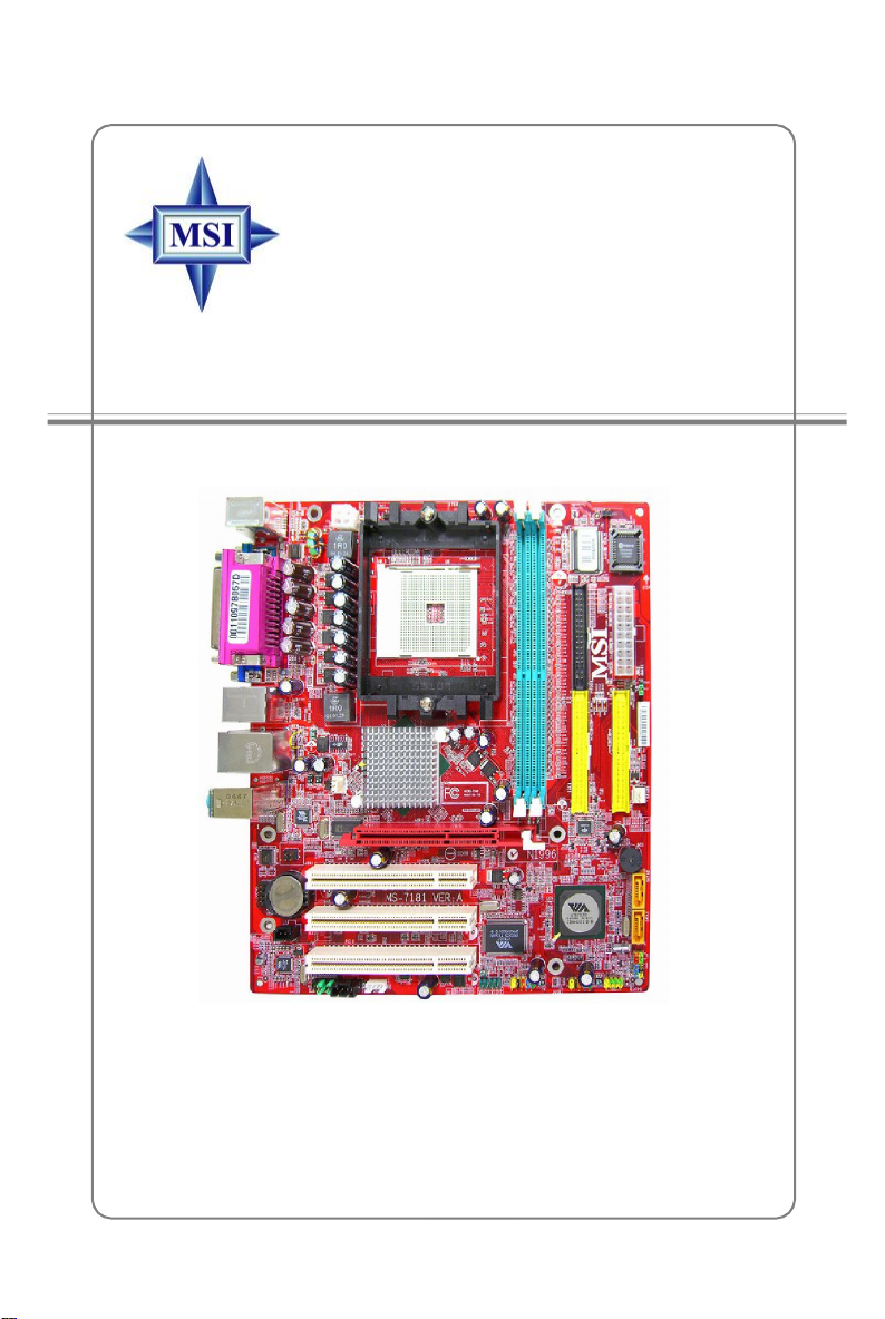
K8MM3 Series
MS-7181 (v2.X) Micro-ATX Mainboard
English / French / German
Version
G52-M7181X5
i
Page 2
FCC-B Radio Frequency Interference Statement
This equipment has been tested
and found to comply with the
limits for a class B digital device,
pursuant to part 15 of the FCC
rules. These limits are designed to provide reasonable protection against harmful
interference in a residential installation. This equipment generates, uses and can radiate
radio frequency energy and, if not installed and used in accordance with the instruction
manual, may cause harmful interference to radio communications. However, there is
no guarantee that interference will not occur in a particular installation. If this equipment
does cause harmful interference to radio or television reception, which can be determined
by turning the equipment off and on, the user is encouraged to try to correct the
interference by one or more of the measures listed below.
=Reorient or relocate the receiving antenna.
=ncrease the separation between the equipment and receiver.
=Connect the equipment into an outlet on a circuit different from that to which the
receiver is connected.
=Consult the dealer or an experienced radio/television technician for help.
Notice 1
The changes or modifications not expressly approved by the party responsible for
compliance could void the user’s authority to operate the equipment.
Notice 2
Shielded interface cables and A.C. power cord, if any, must be used in order to comply
with the emission limits.
VOIR LA NOTICE D’INSTALLATION AVANT DE RACCORDER AU RESEAU.
Micro-Star International
MS-7181
This device complies with Part 15 of the FCC Rules. Operation is subject to the
following two conditions:
(1) this device may not cause harmful interference, and
(2) this device must accept any interference received, including interference that
may cause undesired operation
ii
Page 3

Copyright Notice
The material in this document is the intellectual property of MICRO-STAR
INTERNATIONAL. We take every care in the preparation of this document, but no
guarantee is given as to the correctness of its contents. Our products are under
continual improvement and we reserve the right to make changes without notice.
Trademarks
All trademarks are the properties of their respective owners.
AMD, Athlon™, Athlon™ XP, Thoroughbred™ , and Duron™ are registered
trademarks of AMD Corporation.
Intel® and Pentium® are registered trademarks of Intel Corporation.
PS/2 and OS®/2 are registered trademarks of International Business Machines
Corporation.
Microsoft is a registered trademark of Microsoft Corporation. Windows® 98/2000/NT/
XP are registered trademarks of Microsoft Corporation.
NVIDIA, the NVIDIA logo, DualNet, and nForce are registered trademarks or trademarks of NVIDIA Corporation in the United States and/or other countries.
Netware® is a registered trademark of Novell, Inc.
Award® is a registered trademark of Phoenix Technologies Ltd.
AMI® is a registered trademark of American Megatrends Inc.
Kensington and MicroSaver are registered trademarks of the Kensington Technology
Group.
PCMCIA and CardBus are registered trademarks of the Personal Computer Memory
Card International Association.
Revision History
Revision Revision History Date
V2.1 Release for EU (RoHS version) February 2006
with VIA K8M800 & VT8237R/ VT8237R Plus
iii
Page 4

Technical Support
If a problem arises with your system and no solution can be obtained from the user’ s
manual, please contact your place of purchase or local distributor. Alternatively,
please try the following help resources for further guidance.
† Visit the MSI homepage & FAQ site for technical guide, BIOS updates, driver
updates, and other information: http://www.msi.com.tw & http://www.msi.
com.tw/program/service/faq/faq/esc_faq_list.php
† Contact our technical staff at: support@msi.com.tw
Safety Instructions
1. Always read the safety instructions carefully.
2. Keep this User’s Manual for future reference.
3. Keep this equipment away from humidity.
4. Lay this equipment on a reliable flat surface before setting it up.
5. The openings on the enclosure are for air convection hence protects the equipment from overheating. Do not cover the openings.
6. Make sure the voltage of the power source and adjust properly 110/220V before connecting the equipment to the power inlet.
7. Place the power cord such a way that people can not step on it. Do not place
anything over the power cord.
8. Always Unplug the Power Cord before inserting any add-on card or module.
9. All cautions and warnings on the equipment should be noted.
10. Never pour any liquid into the opening that could damage or cause electrical
shock.
11. If any of the following situations arises, get the equipment checked by a service
personnel:
† The power cord or plug is damaged.
† Liquid has penetrated into the equipment.
† The equipment has been exposed to moisture.
† The equipment has not work well or you can not get it work according to
User’s Manual.
† The equipment has dropped and damaged.
† The equipment has obvious sign of breakage.
12. Do not leave this equipment in an environment unconditioned, storage
temperature above 600 C (1400F), it may damage the equipment.
CAUTION: Danger of explosion if battery is incorrectly replaced.
Replace only with the same or equivalent type recommended by the
manufacturer.
iv
Page 5
WEEE Statement
v
Page 6
vi
Page 7
vii
Page 8

CONTENTS
FCC-B Radio Frequency Interference Statement..........................................................ii
Copyright Notice..............................................................................................................iii
Revision History..............................................................................................................iii
Technical Support..........................................................................................................iv
Safety Instructions.........................................................................................................iv
WEEE Statement......................................................................................................v
English.....................................................................................................................E-1-1
1. Getting Started.............................................................................................E-1-3
2. Hardware Setup..........................................................................................E-2-1
3. BIOS Setup...................................................................................................E-3-1
Français......................................................................................................................F-1
Guide d’Utilisation..................................................................................................F-3
Deutsch......................................................................................................................G-1
Benutzerhandbuch...............................................................................................G-3
viii
Page 9

Getting Started
K8MM3 Series
User’s Guide
English
E-1-1
Page 10

MS-7181 Micro-ATX Mainboard
E-1-2
Page 11

Getting Started
Chapter 1. Getting
Started
Getting Started
Thank you for purchasing the K8MM3 (MS-7181 v2.X) series,
an excellent Micro-ATX mainboard from MSI. Based on the innovative
VIA K8M800 and VIA VT8237R/ VT8237R Plus chipsets for optimal
system efficiency, the K8MM3 serias mainboard accommodates latest
AMD K8 processor in the 754-pin lidded ceramic micro PGA package,
and supports up to 2 DIMMs to provide the maximum of 2 GB memory
capacity. This mainboard provides a high professional desktop platform
solution.
E-1-3
Page 12

MS-7181 Micro-ATX Mainboard
Mainboard Specifications
CPU
† Supports 64-bit AMD® K8 Athlon 64/ Sempron processor (Socket 754).
† Supports 3700+ or higher CPU.
Chipset
† VIA K8M800 Chipset
-HyperTransportTM connection to AMD K8 Athlon64/ Sempron processor
-8 or 16 bit control/address/data transfer both directions
-800/600/400/200 MHz “Double Data Rate” operation both direction
-AGP v3.0 compliant with 8x transfer mode
-Graphic integrated
† VIA VT8237R/ VT8237R Plus Chipset
- Integrated Hardware Sound Blaster/Direct Sound AC97 audio
- Ultra DMA 66/100/133 master mode PCI EIDE controller
- ACPI& PC2001 compliant enhanced power management
- Supports dual channel native SATA controller up to 150MB/s
- Supports SATA RAID 0 or RAID 1
- Supports 8 USB2.0 ports
- Supports SATA2 Device (for VT8237R Plus only.)
Main Memory
† Supports DDR266/333/400 DDR SDRAM, and unbuffered DIMMs for two
184- pin DDR DIMMs.
† Supports DIMM sizes up to 2GB of memory in total.
Slots
† One AGP 8x/4x slot.
† Three 32-bit/33 MHz PCI slots.
On-Board IDE
† An IDE controller on the VT8237R/VT8237R Plus chipset provides IDE HDD/CD-
ROM with PIO, Bus Master and Ultra DMA133/100/66 operation modes.
- Can connect up to four Ultra ATA drives.
† Serial ATA/150 controller integrated in VT8237R/ VT8237RPlus.
- Up to 150MB/sec transfer speeds. (VT8237R Plus supports SATA2 device.)
- Can connect up to two Serial ATA drives.
- Supports RAID 0 or 1
E-1-4
Page 13

Getting Started
On-Board Peripherals
† On-Board Peripherals include:
- 1 floppy port supports 1 FDDs with 360K, 720K, 1.2M, 1.44M and 2.88Mbytes
- 2 serial ports (Rear * 1/ Front * 1)
- 1 VGA port onboard
- 1 parallel port supports SPP/EPP/ECP mode
- 1 IrDA pinheader (optional)
- 1 CD-In pinheader
- 1 Aux-In pinheader
- 1SPDIF out pinheader (optional)
- 1 audio port (Line-in/Line-out/MIC)
- 8 USB 1.1/2.0 ports (Rear * 4/ Front * 4)
IEEE 1394 (Optional)
† Supports up to 2 * 1394 ports (Rear * 1/ onboard header * 1).
Transfer rate is up to 400Mbps
† Controlled by VIA 6307 chipset
Audio
† AC’97 link controller integrated in VIA VT8237R/ VT8237R Plus.
† 6 channels software audio codec VIA VT1617A
- Compliance with AC97 v2.3 Spec.
- Meet PC2001 audio performance requirement.
LAN
† VIA VT8237R/ VT8237R Plus MAC + VIA 6103 Ethernet PHY
- Supports 10/100Mb/s auto-negotiation operation.
- Compliant with PCI v2.2 and PC99 standard.
- Supports ACPI Power Management.
BIOS
† The mainboard BIOS provides “Plug & Play” BIOS which detects the peripheral
devices and expansion cards of the board automatically.
† The mainboard provides a Desktop Management Interface (DMI) function which
records your mainboard specifications.
Dimension and Mounting
† Micro-ATX Form Factor: 24.4 cm (L) x 21.5 cm (W).
† 6 mounting holes
E-1-5
Page 14
MS-7181 Micro-ATX Mainboard
AGP1
IDE 1IDE
2
SATA2FDD 1JWR
2
BIOS
JBAT1WinbondW83627THF
JSP1
JIR1
(optional)
VT8237R/Plus
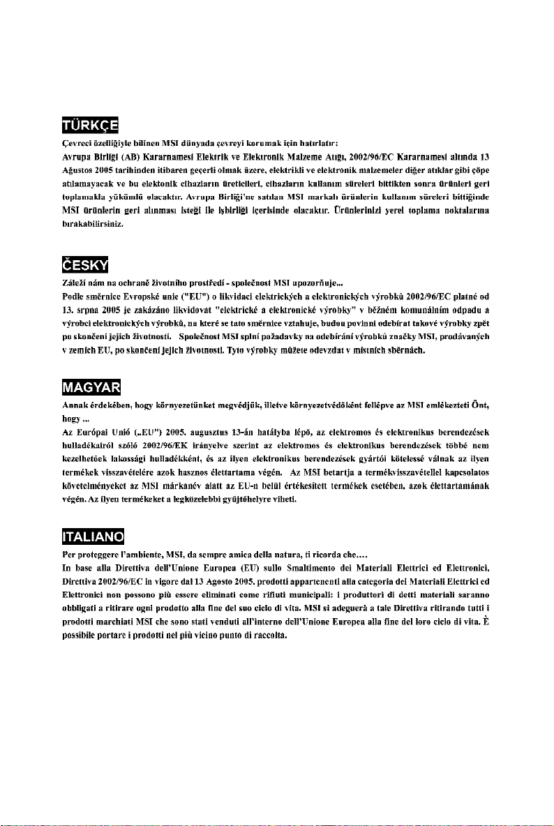
Mainboard Layout
Top : mouse
Bottom: keyboard
Top :
Parallel Port
Bottom:
COM Port
VGA Port
Top :1394 port
B:USB ports
Top: LAN Jack
Bottom: USB
ports
T:
Line-In
Line-Out
M:
B:Mic
JCOM1
VT1617A
JPW1
VIA
K8M800
CPUFAN1
VIA
VT6103L
PCI1
BATT
+
PCI2
PCI3
VIA
JAUD1 JCD1 JAUX1 J1394_1
DDR1DDR2
VIA
VT6307
JUSB2 JUSB1
JCI1
SFAN1
VIA
SATA1
JFP1
JFP2
K8MM3 (MS-7181 v2.X) series Mainboard
E-1-6
Page 15
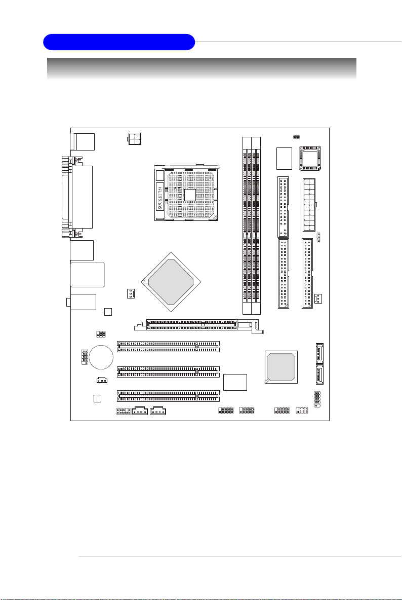
Packing Contents
Getting Started
MSI motherboard
SATA Cable/
Power Cable (Optional)
1394 Cable
(Optional)
MSI Driver/Utility CD
Flat Cable of
Floppy Disk
SATA RAID Driver
Diskette
Flat Cable of
IDE Devices
User’ s GuideBack IO Shield
SPDIF-Bracket
(Optional)
* The pictures are for reference only and may vary from the packing contents of the
product you purchased.
USB Bracket
(Optional)
E-1-7
Page 16

Hardware Setup
Chapter 2. Hardware
Setup
Hardware Setup
This chapter provides you with the information about hardware setup
procedures. While doing the installation, be careful in holding the components and follow the installation procedures. For some components,
if you install in the wrong orientation, the components will not work
properly.
Use a grounded wrist strap before handling computer components.
Static electricity may damage the components.
E-2-1
Page 17
MS-7181 Micro-ATX Mainboard
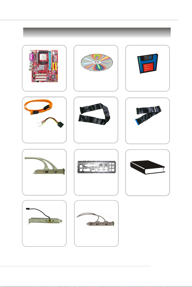
Quick Components Guide
I/O Ports,
p.2-9
CPUFAN1,
p.2-14
JIR1, p.2-19
JCOM1, p.2-18
JSP1, p.2-20
JPW1, p.2-8
CPU, p.2-3
JAUX1, p.2-18
JCD1, p.2-18
JAUD1, p.2-19
DIMM1-2, p.2-6
JUSB1/2, p.2-15
J1394_1, p.2-20
JCI1, p.2-18
FDD1, p.2-14
JWR1, p.2-8
JBAT1, p.2-21
IDE1, IDE2,
p.2-15
SFAN1,
p.2-14
AGP slot, p.2-22
PCI slots, p.2-22
SATA1/2, p.2-16
JFP1, p.2-17
JFP2, p.2-17
E-2-2
Page 18
Hardware Setup
Central Processing Unit: CPU
The mainboard supports AMD® Athlon64/ Sempron processor. The mainboard uses a
CPU socket called Socket-754 for easy CPU installation. When you are installing the
CPU, make sure the CPU has a heat sink and a cooling fan attached on the
top to prevent overheating. If you do not have the heat sink and cooling fan,
contact your dealer to purchase and install them before turning on the computer.
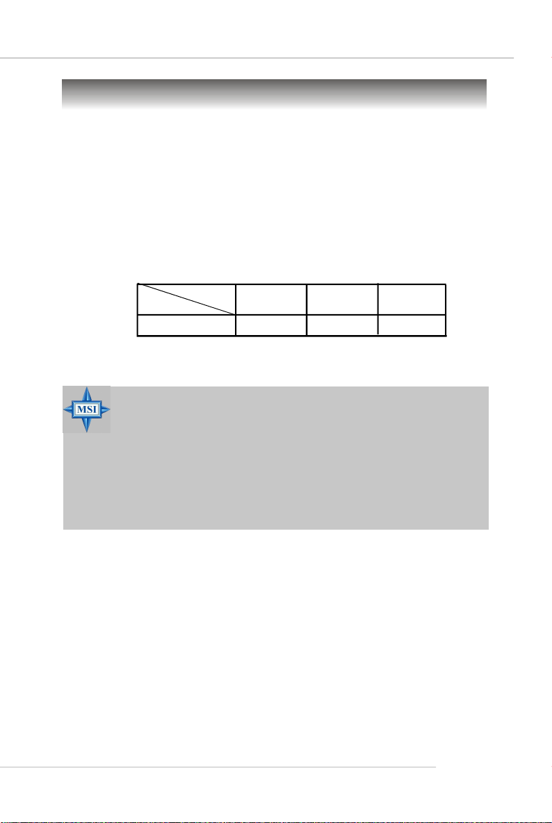
Memory Speed/CPU FSB Support Matrix
DDR 266
FSB 800
MSI Reminds You...
Overheating
Overheating will seriously damage the CPU and system, always make
sure the cooling fan can work properly to protect the CPU from
overheating.
Replacing the CPU
While replacing the CPU, always turn off the ATX power supply or
unplug the power supply’s power cord from grounded outlet first to
ensure the safety of CPU.
OK OK
DDR 333
DDR 400
OK
E-2-3
Page 19
MS-7181 Micro-ATX Mainboard
Gold arrow
Gold arrow
Gold arrow
Correct CPU placement
Incorrect CPU placement
Close
Press down
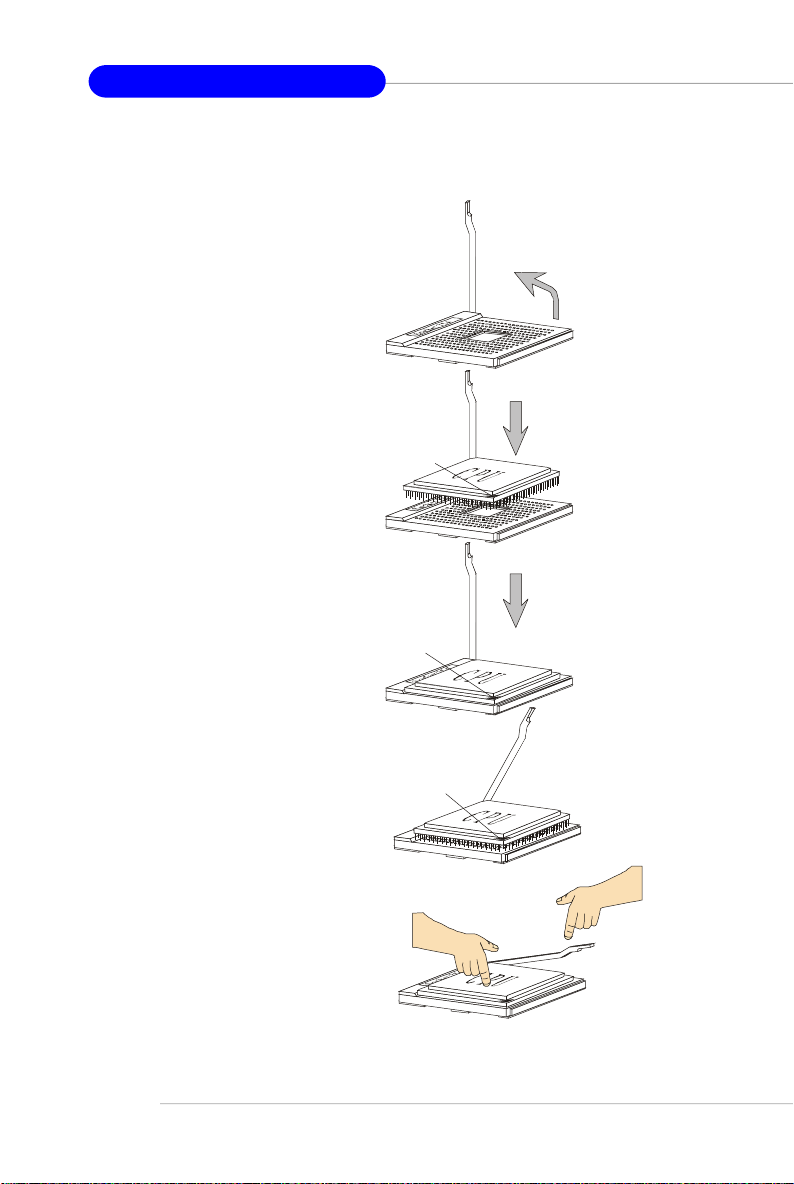
CPU Installation Procedures for Socket 754
1. Please turn off the power and
unplug the power cord before
installing the CPU.
Open Lever
2. Pull the lever sideways away
from the socket. Make sure to
raise the lever up to a 90-degree angle.
3.Look for the gold arrow. The gold
arrow should point as picture
shown. The CPU can only fit in
the correct orientation.
4.If the CPU is correctly installed,
the pins should be completely
embedded into the socket and
can not be seen. Please note
that any violation of the correct
installation procedures may
cause permanent damages to
your mainboard.
5. Press the CPU down firmly into
the socket and close the lever.
As the CPU is likely to move while
the lever is being closed, always close the lever with your
fingers pressing tightly on top of
the CPU to make sure the CPU is
properly and completely embedded into the socket.
Sliding
Plate
90 degree
O
X
the CPU
Lever
E-2-4
Page 20
Hardware Setup
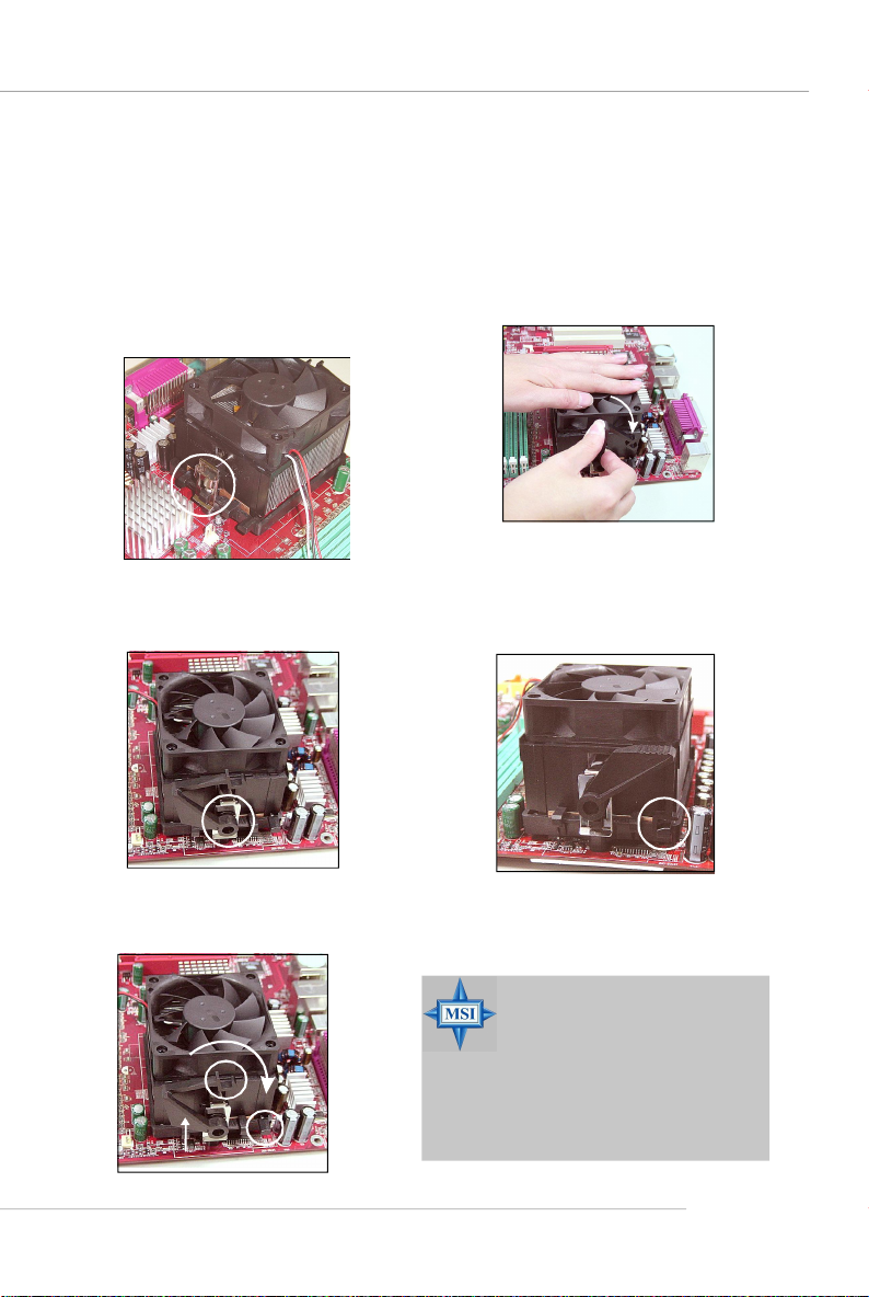
Installing AMD Athlon64 CPU Cooler Set
When you are installing the CPU, make sure the CPU has a heat sink and a
cooling fan attached on the top to prevent overheating. If you do not have the
heat sink and cooling fan, contact your dealer to purchase and install them before
turning on the computer.
1.Position the cooling set onto the
retention mechanism. Hook one
end of the clip to hook first.
4.Fasten down the lever.
2.Press down the other end of the
clip to fasten the cooling set on
the top of the retention
mechanism.
3.Locate the Fix Lever, Safety Hook
and the Fixed Bolt. Lift up the intensive fixed lever.
Safety
Fixed Lever
Fixed Bolt
5.Make sure the safety hook
completely clasps the fixed
bolt of the retention
mechanism.
6. Connect the fan power cable
from the mounted fan to the
CPUFAN1 connector on the
board
MSI Reminds You...
While disconnecting the Safety
Hook from the fixed bolt, it is
necessary to keep an eye on
your fingers, because once the
Safety Hook is disconnected
from the fixed bolt, the fixed
lever will spring back instantly.
E-2-5
Page 21
MS-7181 Micro-ATX Mainboard
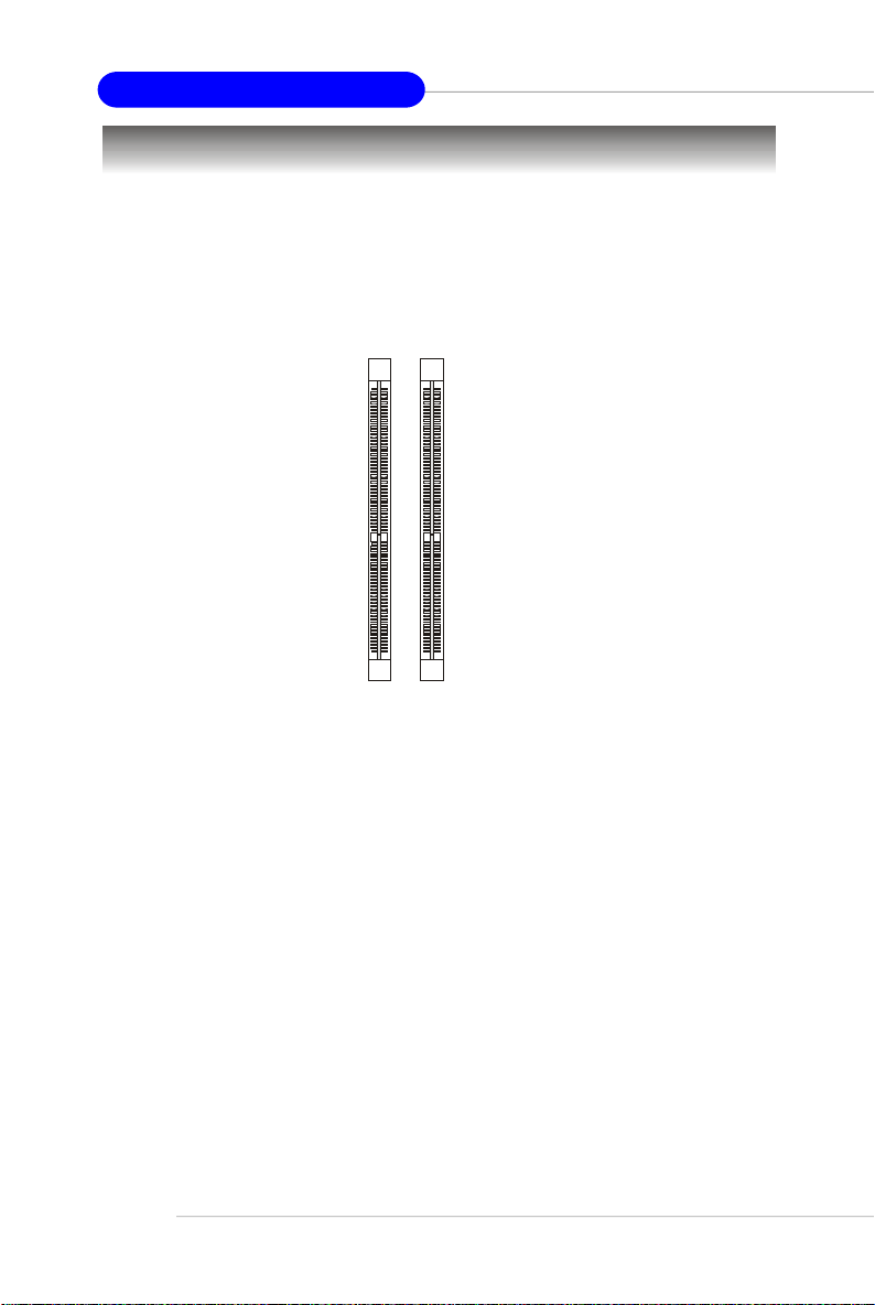
Memory
The mainboard provides two slots for 184-pin DDR SDRAM DIMM (Double In-Line
Memory Module) modules and supports up to 2GB memory size. You can install
PC3200/DDR400, PC2700/DDR333 & PC2100/DDR266 modules on the DDR DIMM slots
(DDR 1~2).
For the updated supporting memory modules, please visit http://www.msi.com.tw/
program/products/mainboard/mbd/pro_mbd_trp_list.php.
DDR DIMM Slots
(DIMM1~2)
Introduction to DDR SDRAM
DDR (Double Data Rate) SDRAM is similar to conventional SDRAM, but doubles the
rate by transferring data twice per cycle. It uses 2.5 volts as opposed to 3.3 volts
used in SDR SDRAM, and requires 184-pin DIMM modules rather than 168-pin DIMM
modules used by SDR SDRAM. High memory bandwidth makes DDR an ideal solution
for high performance PC, workstations and servers.
E-2-6
Page 22

Hardware Setup
DDR DIMM Module Combination
Install at least one DIMM module on the slots. Memory modules can be installed on the
slots in any order. You can install either single- or double-sided modules to meet your
own needs.
Memory modules can be installed in any combination as follows:
Slot Memory Module Total Memory
DIMM 1
S/D 64MB~1GB
(Bank 0 & 1)
DIMM 2
S/D 64MB~1GB
(Bank 2 & 3)
Maximum System Memory Supported
S: Single Side D: Double Side
64MB~2GB
Installing DDR Modules
1. The DDR DIMM has only one notch on the center of module. The module will only
fit in the right orientation.
2. Insert the DIMM memory module vertically into the DIMM slot. Then push it in until
the golden finger on the memory module is deeply inserted in the socket.
3. The plastic clip at each side of the DIMM slot will automatically close.
Volt
MSI Reminds You...
You can barely see the golden finger if the module is properly inserted
in the socket.
Notch
E-2-7
Page 23
MS-7181 Micro-ATX Mainboard
Power Supply
The mainboard supports ATX power supply for the power system. Before inserting
the power supply connector, always make sure that all components are installed
properly to ensure that no damage will be caused.
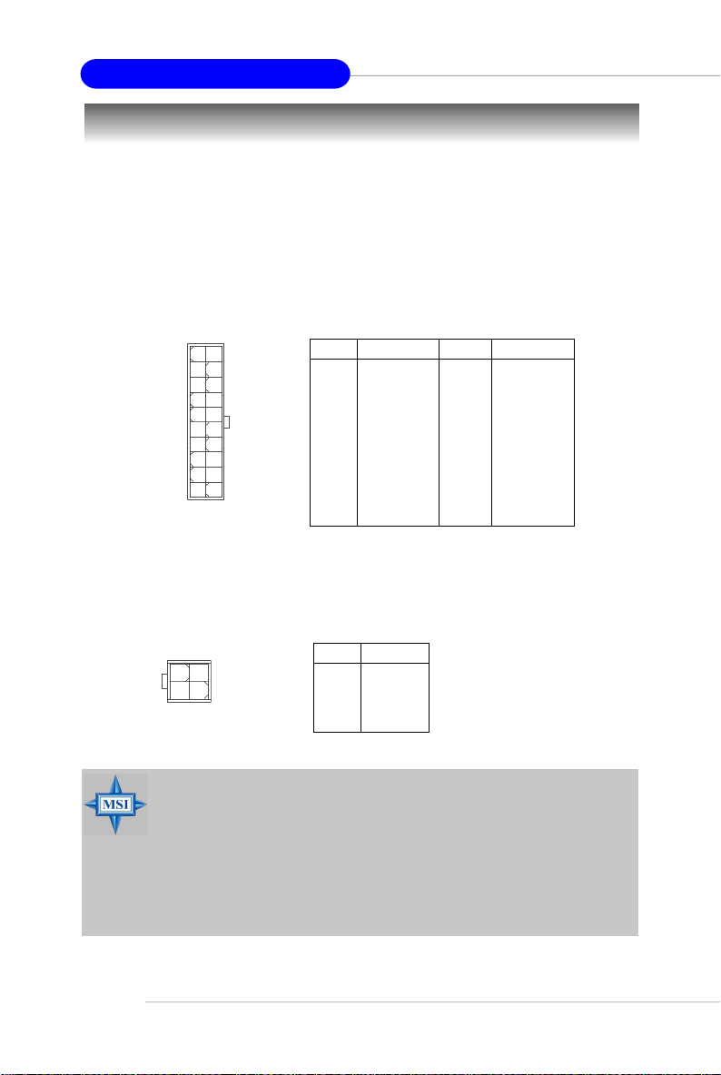
ATX 20-Pin Power Connector: JWR1
This connector allows you to connect to an ATX power supply. To connect to the ATX
power supply, make sure the plug of the power supply is inserted in the proper
orientation and the pins are aligned. Then push down the power supply firmly into the
connector.
10
20
1
11
JWR1
ATX 12V Power Connector: JPW1
This 12V power connector is used to provide power to the CPU.
JWR1 Pin Definition
PIN SIGNAL
1 3.3V
2 3.3V
3 GND
4 5V
5 GND
6 5V
7 GND
8 PW_OK
9 5V_SB
10 12V
PIN SIGNAL
11 3.3V
12 -12V
13 GND
14 PS_ON
15 GND
16 GND
17 GND
18 -5V
19 5V
20 5V
E-2-8
4 2
3
JPW1
1
PIN SIGNAL
1 GND
2 GND
3 12V
4 12V
JPW1 Pin Definition
MSI Reminds You...
There is a mechanism of this mainboard to protect it from being
damaged. The power will shut down automatically in two conditions: the
temperature of CPU reaches 100oC, or the low voltage occurs during
booting up. Please follow the instructions below for this issue:
1. The power LED will blink continously. You should unplug the power
cord or turn off the power switch.
2.After the power LED stop blinking, plug on the power cord or turn on
the power switch, then you can reboot your system again.
Page 24
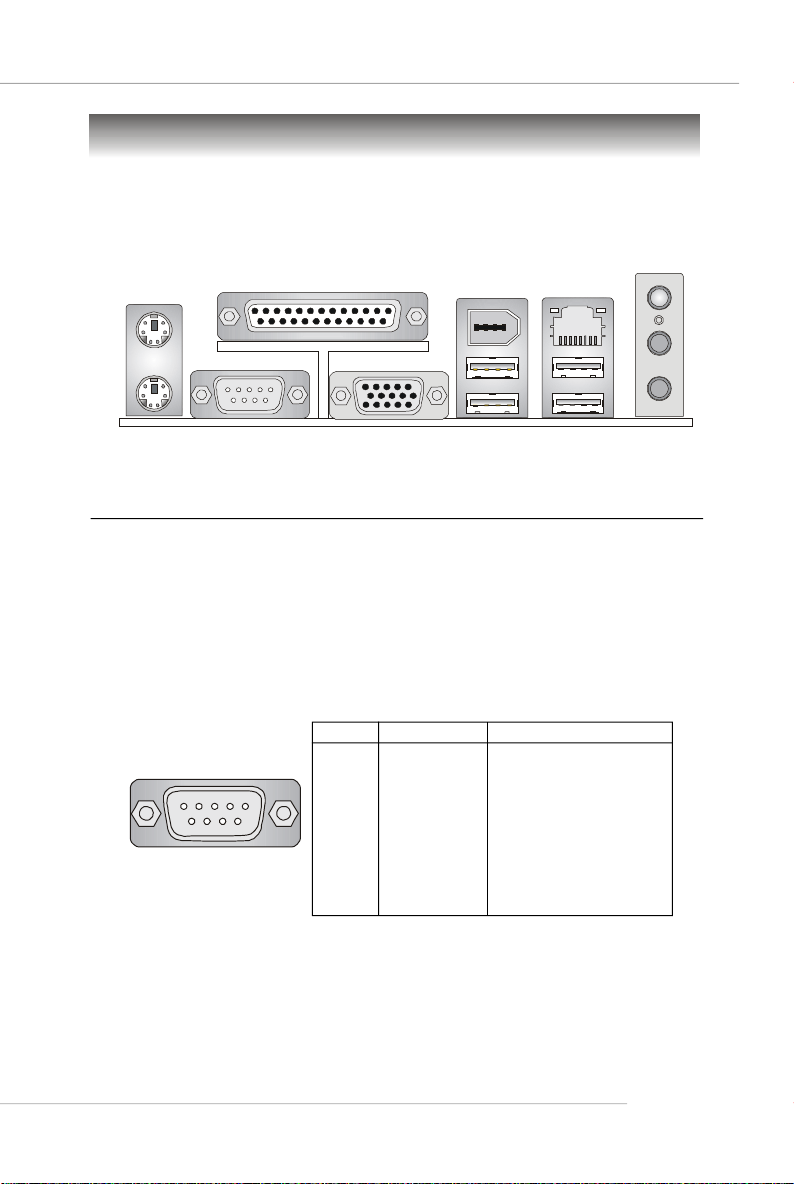
Back Panel
View of the Back Panel
The back panel provides the following connectors:
Hardware Setup
L-in
L-out
Mouse
Keyboard
COM 1
Parallel
VGA Port
1394
Port
USB Ports
LAN
USB Ports
MIC
Serial Port: COM1
The mainboard provides one 9-pin mail DIN connector as serial port COM1. The serial
port is a 16550A high speed communication port that sends/receives 16 bytes FIFOs.
You can attach a serial mouse or other serial device directly to it.
Pin Definition
PIN SIGNAL DESCRIPTION
1 2 3 4 5
6 7 8 9
COM1
1 DCD Data Carry Detect
2 SIN Serial In or Receive Data
3 SOUT Serial Out or Transmit Data
4 DTR Data Terminal Ready
5 GND Ground
6 DSR Data Set Ready
7 RTS Request To Send
8 CTS Clear To Send
9 RI Ring Indicate
E-2-9
Page 25
MS-7181 Micro-ATX Mainboard
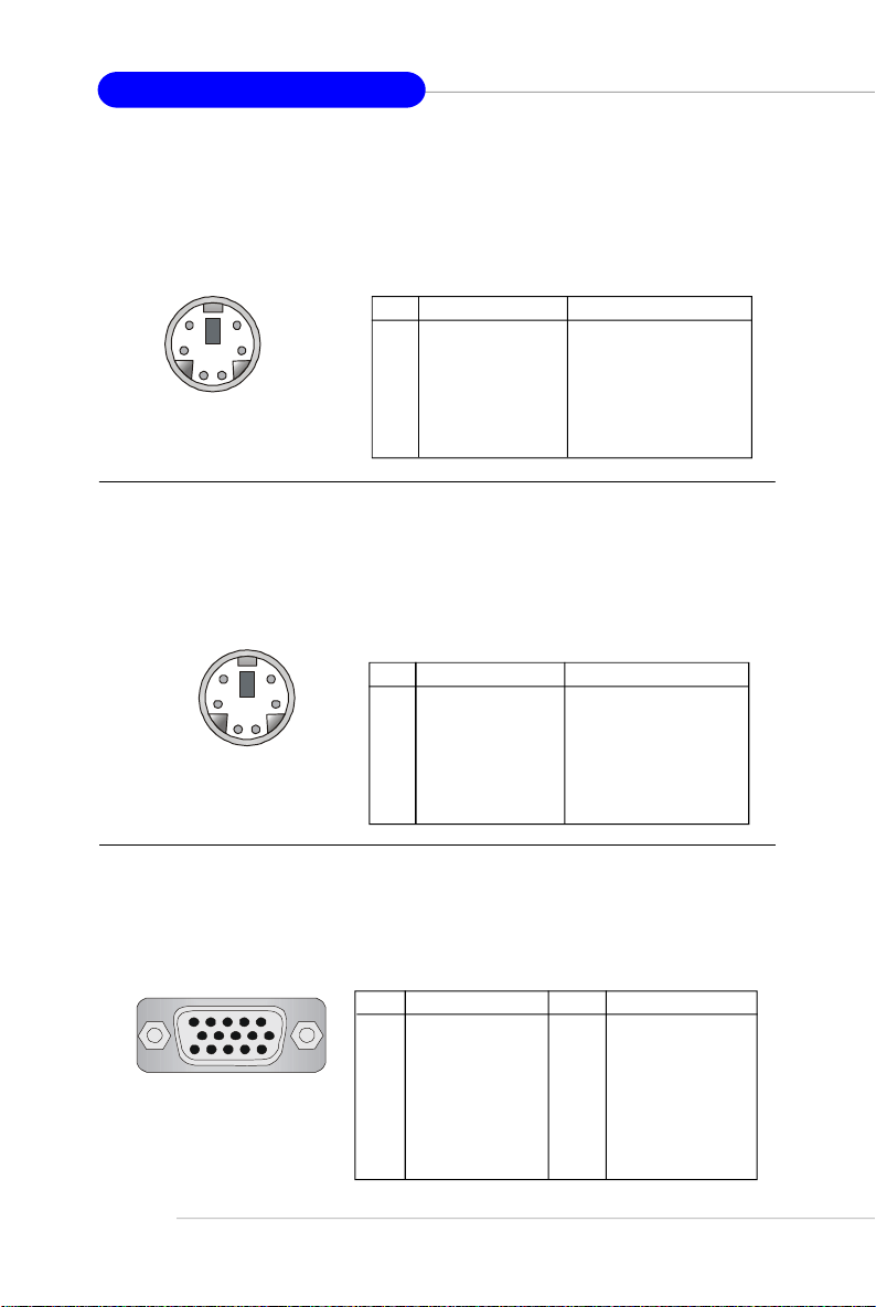
Mouse Connector
The mainboard provides a standard PS/2® mouse mini DIN connector for attaching a
PS/2® mouse. You can plug a PS/2® mouse directly into this connector. The connector
location and pin assignments are as follows.
Pin Definition
6
4
2
5
1
PS/2 Mouse
(6-pin Female)
3
PIN SIGNAL DESCRIPTION
1 Mouse Data Mouse data
2 NC No connection
3 GND Ground
4 VCC +5V
5 Mouse Clock Mouse clock
6 NC No connection
Keyboard Connector
The mainboard provides a standard PS/2® keyboard mini DIN connector for attaching
a PS/2® keyboard. You can plug a PS/2® keyboard directly into this connector. The
connector location and pin assignments are as follows.
Pin Definition
6
4
2
PS/2 Keyboard
(6-pin Female)
5
3
1
PIN SIGNAL DESCRIPTION
1 Keyboard Data Keyboard data
2 NC No connection
3 GND Ground
4 VCC +5V
5 Keyboard Clock Keyboard clock
6 NC No connection
VGA Connector
The mainboard provides a DB 15-pin female connector to connect a VGA monitor.
Pin Definition
Pin Signal Description
9 +5V
10 GND
11 N/C
12 SDA
13 Horizontal Sync
14 Vertical Sync
15 SCL
VGA Connector
E-2-10
5
15
(DB 15-pin)
1
11
Pin Signal Description
1 RED
2 GREEN
3 BLUE
4 N/C
5 GND
6 GND
7 GND
8 GND
Page 26
Hardware Setup
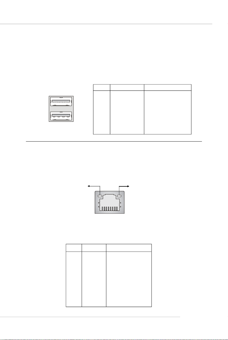
USB Ports
The mainboard provides a UHCI (Universal Host Controller Interface) Universal Serial
Bus root for attaching USB devices such as keyboard, mouse or other USB-compatible devices. You can plug USB devices directly into the ports.
Pin Definition
PIN SIGNAL DESCRIPTION
1 2 3 4
5 6 7 8
USB Ports
1 VCC +5V
2 -Data 0 Negative Data Channel 0
3 +Data 0 Positive Data Channel 0
4 GND Ground
5 VCC +5V
6 -Data 1 Negative Data Channel 1
7 +Data 1 Positive Data Channel 1
8 GND Ground
RJ-45 LAN Jack
The mainboard provides one standard RJ-45 jack for connection to Local Area Network (LAN). You can connect a network cable to the LAN jack.
Activity Indicator
8 1
RJ-45 LAN Jack
10/100 LAN Pin Definition
PIN SIGNAL DESCRIPTION
1 TDP Transmit Differential Pair
2 TDN Transmit Differential Pair
3 RDP Receive Differential Pair
4 NC Not Used
5 NC Not Used
6 RDN Receive Differential Pair
7 NC Not Used
8 NC Not Used
Link Indicator
E-2-11
Page 27

MS-7181 Micro-ATX Mainboard
IEEE 1394 Port
The back panel provides one standard IEEE 1394 port. The IEEE1394 high-speed
serial bus complements USB by providing enhanced PC connectivity for a wide range
of devices, including consumer electronics audio/video (A/V) appliances, storage
peripherals, other PCs, and portable devices.
IEEE1394 Port
Audio Port Connectors
Line Out is a connector for Speakers or Headphones. Line In is used for external
CD player, Tape player, or other audio devices. Mic is a connector for microphones.
Line In
Line Out
E-2-12
MIC
MSI Reminds You...
For advanced audio application, VIA VT1617 audio chip is provided
to offer support for 6-channel audio operation and can turn rear
audio connectors from 2-channel to 4-/6-channel audio.
Page 28
Hardware Setup
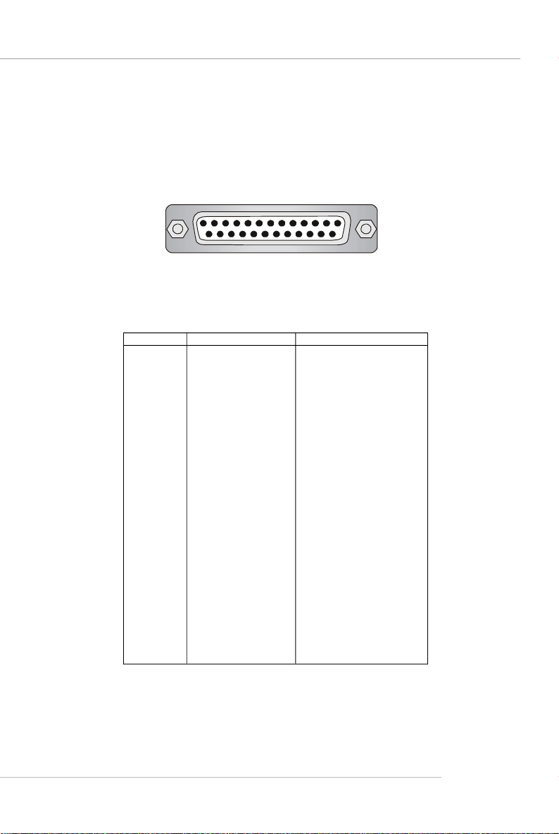
Parallel Port
The mainboard provides a 25-pin female centronic connector as LPT. A parallel port
is a standard printer port that supports Enhanced Parallel Port (EPP) and Extended
Capabilities Parallel Port (ECP) mode.
13 1
25
14
Pin Definition
PIN SIGNAL DESCRIPTION
1 STROBE Strobe
2 DATA0 Data0
3 DATA1 Data1
4 DATA2 Data2
5 DATA3 Data3
6 DATA4 Data4
7 DATA5 Data5
8 DATA6 Data6
9 DATA7 Data7
10 ACK# Acknowledge
11 BUSY Busy
12 PE Paper End
13 SELECT Select
14 AUTO FEED# Automatic Feed
15 ERR# Error
16 INIT# Initialize Printer
17 SLIN# Select In
18 GND Ground
19 GND Ground
20 GND Ground
21 GND Ground
22 GND Ground
23 GND Ground
24 GND Ground
25 GND Ground
E-2-13
Page 29
MS-7181 Micro-ATX Mainboard
Connectors
The mainboard provides connectors to connect FDD, IDE HDD, front panel of the
system case, audio ports, USB Ports, and CPU/System FANs.
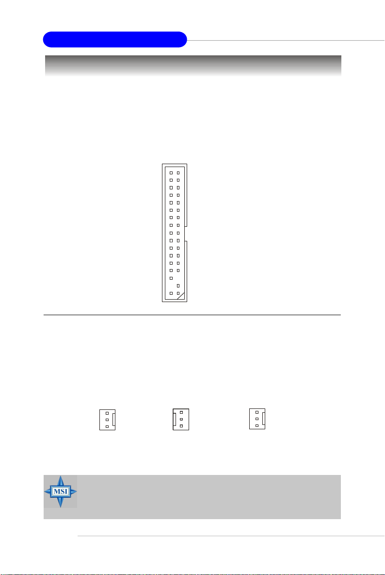
Floppy Disk Drive Connector: FDD1
The mainboard provides a standard floppy disk drive connector that supports 360KB,
720KB, 1.2MB, 1.44MB and 2.88MB floppy disk types.
FDD1
Fan Power Connectors: CPUFAN1, SFAN1
The CPUFAN1 (processor fan) and SFAN1 (system fan) support system cooling fan
with +12V. It supports 3-pin head connector. When connecting the wire to the
connectors, always take note that the red wire is the positive and should be connected to the +12V, the black wire is Ground and should be connected to GND. If the
mainboard has a System Hardware Monitor chipset on-board, you must use a specially designed fan with speed sensor to take advantage of the CPU fan control.
SENSOR
+12V
GND
Fan Connector
Pin Definition
E-2-14
CPUFAN1
SFAN1
MSI Reminds You...
1. Always consult the vendors for proper CPU cooling fan.
2. CPUFAN1 supports Smart Fan control, you may set up the smart fan
control functions in the BIOS setup.
Page 30
Hardware Setup
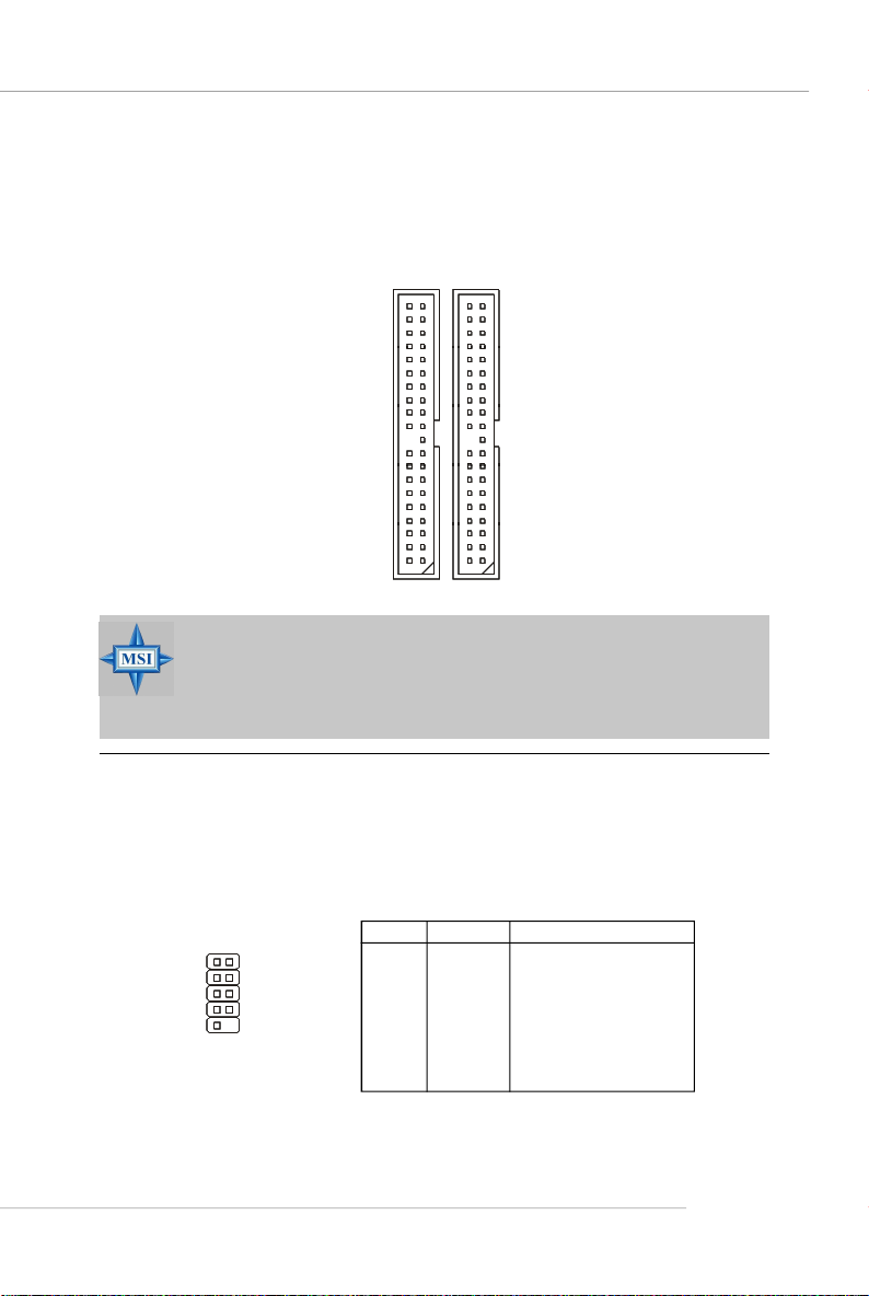
Hard Disk Connectors: IDE1 & IDE2
The mainboard provides a 32-bit Enhanced PCI IDE and Ultra DMA 33/66/100/133
controller that supports PIO mode 0 ~ 4, Bus Master, and Ultra DMA 33/66/100/133
function. You can connect up to four hard disk drives, CD-ROM drives, 120MB floppy
disk drive (reserved for future BIOS), and other devices.
IDE2IDE1
MSI Reminds You...
If you install two hard disks on cable, you must configure the second
drive to Slave mode by setting its jumper. Refer to the hard disk
documentation supplied by hard disk vendors for jumper setting
instructions.
Serial Port Header: JCOM1 (Optional)
The mainboard offers one 9-pin header as serial port. The port is a 16550A high
speed communication port that sends/receives 16 bytes FIFOs. You can attach a
serial mouse or other serial device directly to it.
Pin Definition
PIN SIGNAL DESCRIPTION
1
5
JCOM1
6
9
1 DCD Data Carry Detect
2 SIN Serial In or Receive Data
3 SOUT Serial Out or Transmit Data
4 DTR Data Terminal Ready)
5 GND Ground
6 DSR Data Set Ready
7 RTS Request To Send
8 CTS Clear To Send
9 RI Ring Indicate
E-2-15
Page 31

MS-7181 Micro-ATX Mainboard
Serial ATA/Serial ATA RAID Connectors controlled by VT8237R/
VT8237R Plus: SATA1 & SATA2
The Southbridge of this mainboard is VIA VT8237R/ VT8237R Plus which supports
two serial connectors SATA1& SATA2.
SATA1 & SATA2 are dual high-speed Serial ATA interface ports. Each supports 1
generation serial ATA data rates of 150 MB/s. Both connectors are fully compliant
with Serial ATA 1.0 specifications. Each Serial ATA connector can connect to 1 hard
disk device.
st
SATA2
17
17
SATA1
Optional Serial ATA cable
SATA1 & SATA2 Pin Definition
Pin Signal Pin Signal
1 GND 2 TXP
3 TXN 4 GND
5 RXN 6 RXP
7 GND
Take out the dust cover and
connect to the hard disk
devices
Connect to SATA1 or SATA2
E-2-16
MSI Reminds You...
Please do not fold the serial ATA cable in a 90-degree angle, which will
cause the loss of data during the transmission.
Page 32

Hardware Setup
Front Panel Connectors: JFP1 & JFP2
The mainboard provides two front panel connectors for electrical connection to the
front panel switches and LEDs. JFP1 is compliant with Intel® Front Panel I/O Connectivity Design Guide.
Power
7
8
LED
Speaker
1
2
12
Power
LED
Power
Switch
10
9
JFP2
JFP1
HDD
LED
Reset
Switch
JFP1 Pin Definition
PIN SIGNAL DESCRIPTION
1 HD_LED_P Hard disk LED pull-up
2 FP PWR/SLP MSG LED pull-up
3 HD_LED_N Hard disk active LED
4 FP PWR/SLP MSG LED pull-up
5 RST_SW_N Reset Switch low reference pull-down to GND
6 PWR_SW_P Power Switch high reference pull-up
7 RST_SW_P Reset Switch high reference pull-up
8 PWR_SW_N Power Switch low reference pull-down to GND
9 RSVD_DNU Reserved. Do not use.
JFP2 Pin Definition
PIN SIGNAL PIN SIGNAL
1 GND 2 SPK3 SLED 4 BUZ+
5 PLED 6 BUZ-
7 NC 8 SPK+
Chassis Intrusion Switch Connector: JCI1
This connector is connected to a 2-pin chassis switch. If the
chassis is opened, the switch will be short. The system will record
this status and show a warning message on the screen. To clear
the warning, you must enter the BIOS utility and clear the record.
CINTRU GND
1 2
JCI1
E-2-17
Page 33

MS-7181 Micro-ATX Mainboard
Aux Line-In Connector: JAUX1
The connector is for DVD add-on card with Line-in connector.
GND
R
L
JAUX1
CD-In Connector: JCD1
This connector is provided for CD-ROM audio.
JCD1
GND
L
R
Front USB Connectors: JUSB1 & JUSB2
The mainboard provide two front Universal Serial Bus connectors for users to connect to USB ports.
Pin Definition
9
JUSB1/JUSB2
Connected to JUSB1
or JUSB2
1
2 10
Pin Description Pin Description
1 USBPWR 2 USBPWR
3 USBP2- 4 USBP3 5 USBP2+ 6 USBP3+
7 GND 8 GND
9 NC 10 OC #
USB 2.0 Bracket
(optional)
E-2-18
MSI Reminds You...
Note that the pins of VCC and GND must be connected correctly, or
itmay cause some damage.
Page 34

Hardware Setup
Front Panel Audio Connector: JAUD1
The mainboard provides one front audio connector for users to connect the optional
audio cable.
JAUD1
2
1
Pin Definition
PIN SIGNAL DESCRIPTION
1 AUD_MIC Front panel microphone input signal
2 AUD_GND Ground used by analog audio circuits
3 AUD_MIC_BIAS Microphone power
4 AUD_VCC Filtered +5V used by analog audio circuits
5 AUD_FPOUT_R Right channel audio signal to front panel
6 AUD_RET_R Right channel audio signal return from front panel
7 HP_ON Reserved for future use to control headphone amplifier
8 KEY No pin
9 AUD_FPOUT_L Left channel audio signal to front panel
10 AUD_RET_L Left channel audio signal return from front panel
MSI Reminds You...
If you don’t want to connect to the front audio header, pins
5 & 6, 9 & 10 have to be jumpered in order to have signal
output directed to the rear audio ports. Otherwise, the
Line-Out connector on the back panel will not function.
10
9
6
10
5
9
IrDA Infrared Module Header: JIR1
The connector allows you to connect to IrDA Infrared module. You must configure the
setting through the BIOS setup to use the IR function. JIR1 is compliant with Intel
Front Panel I/O Connectivity Design Guide.
652
JIR1
1
JIR1 Pin Definition
Pin Signal
1 NC
2 NC
3 VCC5
4 GND
5 IRTX
6 IRRX
E-2-19
®
Page 35

MS-7181 Micro-ATX Mainboard
IEEE 1394 Connector: J1394_1
The mainboard provides one IEEE1394 pin header that allows you to connect IEEE
1394 port via an external IEEE1394 bracket (optional).
Pin Definition
J1394_1
1
2 10
PIN SIGNAL PIN SIGNAL
1 TPA+ 2 TPA3 Ground 4 Ground
5 TPB+ 6 TPB7 Cable power 8 Cable power
9 Key (no pin) 10 Ground
IEEE1394 Bracket (Optional)
Foolproof
design
9
Connected to J1394_1
SPDIF-Out Connector: JSP1
This connector is used to connect SPDIF (Sony & Philips Digital Interconnect Format)
interface for digital audio transmission.
E-2-20
Connected to JSP1
VCC
SPDIF
JSP1
SPDIF Bracket (Optional)
GND
Page 36

Hardware Setup
Jumpers
The mainboard provides the following jumpers for you to set the computer’ s function.
This section will explain how to change your mainboard’s function through the use of
jumpers.
Clear CMOS Jumper: JBAT1
There is a CMOS RAM on board that has a power supply from external battery to
keep the data of system configuration. With the CMOS RAM, the system can automatically boot OS every time it is turned on. If you want to clear the system configuration,
use the JBAT1 (Clear CMOS Jumper ) to clear data. Follow the instructions below to
clear the data:
3
1
JBAT1
3
1
1
Keep Data Clear Data
MSI Reminds You...
You can clear CMOS by shorting 2-3 pin while the system is off.
Then return to 1-2 pin position. Avoid clearing the CMOS while the
system is on; it will damage the mainboard.
E-2-21
Page 37

MS-7181 Micro-ATX Mainboard
Slots
The motherboard provides one AGP slot and three 32-bit PCI bus slots.
AGP (Accelerated Graphics Port) Slot
The AGP slot allows you to insert the AGP graphics card. AGP is an interface specification designed for the throughput demands of 3D graphics. It introduces a 66MHz,
32-bit channel for the graphics controller to directly access main memory. The slot
supports 8x/4x AGP card.
PCI (Peripheral Component Interconnect) Slots
The PCI slots allow you to insert the expansion cards to meet your needs. When
adding or removing expansion cards, make sure that you unplug the power supply
first. Meanwhile, read the documentation for the expansion card to make any necessary hardware or software settings for the expansion card, such as jumpers,
switches or BIOS configuration.
PCI Interrupt Request Routing
The IRQ, acronym of interrupt request line and pronounced I-R-Q, are hardware lines
over which devices can send interrupt signals to the microprocessor. The PCI IRQ
pins are typically connected to the PCI bus INT A# ~ INT D# pins as follows:
Order 1 Order 2 Order 3 Order 4
PCI Slot 1 INT A# INT B# INT C# INT D#
PCI Slot 2 INT B# INT C# INT D# INT A#
PCI Slot 3 INT C# INT D# INT A# INT B#
E-2-22
Page 38

BIOS Setup
Chapter 3. BIOS Setup
BIOS Setup
This chapter provides information on the BIOS Setup program
and allows you to configure the system for optimum use.
You may need to run the Setup program when:
² An error message appears on the screen during system boot up, and
requests you to run SETUP.
² You want to change the default settings for customized features.
MSI Reminds You...
1. The items under each BIOS category described in this chapter are
under continuous update for better system performance.
Therefore, the description may be slightly different from the latest
BIOS and should be held for reference only.
2. While booting up, the BIOS version is shown in the 1st line appearing after the memory count. It is usually in the format:
example: W7181VMS V2.0 021006
where:
1st digit refers to BIOS maker as A=AMI(R); W=AWARD(R)
2nd - 5th digit refers to the model number.
6th digit refers to VIA chipset.
7th - 8th digit refers to the customer, MS = all standard customers.
V2.0 refers to the BIOS version.
021006 refers to the date this BIOS is released.
E-3-1
Page 39

MS-7181 Micro-ATX Mainboard
Entering Setup
Power on the computer and the system will start POST (Power On Self Test) process.
When the message below appears on the screen, press <DEL> key to enter Setup.
Press DEL to enter SETUP
If the message disappears before you respond and you still wish to enter Setup,
restart the system by turning it OFF and On or pressing the RESET button. You may
also restart the system by simultaneously pressing <Ctrl>, <Alt>, and <Delete> keys.
Selecting the First Boot Device
You are allowed to select the 1st boot device without entering the BIOS setup utility
by pressing <F11>. When the same message as listed above appears on the screen,
press <F11> to trigger the boot menu.
The POST messages might pass by too quickly for you to respond in time. If so, restart
the system and press <F11> after around 2 or 3 seconds to activate the boot menu
similar to the following.
Select First Boot Device
Floppy : 1st Floppy
IDE-0 : IBM-DTLA-307038
CDROM : ATAPI CD-ROM DRIVE 40X M
[Up/Dn] Select [RETURN] Boot [ESC] cancel
The boot menu will list all the bootable devices. Select the one you want to boot from
by using arrow keys, then press <Enter>. The system will boot from the selected
device. The selection will not make changes to the settings in the BIOS setup utility,
so next time when you power on the system, it will still use the original first boot
device to boot up.
E-3-2
Page 40

BIOS Setup
Control Keys
<↑> Move to the previous item
<↓> Move to the next item
<←> Move to the item in the left hand
<→> Move to the item in the right hand
<Enter> Select the item
<Esc> Jumps to the Exit menu or returns to the main menu from a
submenu
<+/PU> Increase the numeric value or make changes
<-/PD> Decrease the numeric value or make changes
<F6> Load Fail-Safe Defaults
<F7> Load Optimized Defaults
<F10> Save all the CMOS changes and exit
Getting Help
After entering the Setup menu, the first menu you will see is the Main Menu.
Main Menu
The main menu lists the setup functions you can make changes to. You can use the
arrow keys ( ↑↓ ) to select the item. The on-line description of the highlighted setup
function is displayed at the bottom of the screen.
Sub-Menu
If you find a right pointer symbol (as shown in the right view) appears to the left of
certain fields, that means a sub-menu can be launched from this field. A sub-menu
contains additional options for a field parameter. You
can use arrow keys ( --> ) to highlight the field and
press <Enter> to call up the sub-menu. Then you can
use the control keys to enter values and move from
field to field within a sub-menu. If you want to return
to the main menu, just press <Esc >.
General Help <F1>
The BIOS setup program provides a General Help screen. You can call up this screen
from any menu by simply pressing <F1>. The Help screen lists the appropriate keys
to use and the possible selections for the highlighted item. Press <Esc> to exit the
Help screen.
E-3-3
Page 41

MS-7181 Micro-ATX Mainboard
The Main Menu
Once you enter Phoenix-Award® BIOS CMOS Setup Utility, the Main Menu will appear
on the screen. The Main Menu allows you to select from the eleven setup functions
and two exit choices. Use arrow keys to select among the items and press <Enter>
to accept or enter the sub-menu.
Standard CMOS Features
Use this menu for basic system configurations, such as time, date etc.
Advanced BIOS Features
Use this menu to setup the items of AWARD® special enhanced features.
Advanced Chipset Features
Use this menu to change the values in the chipset registers and optimize your system’s performance.
Integrated Peripherals
Use this menu to specify your settings for integrated peripherals.
Power Management Setup
Use this menu to specify your settings for power management.
PNP/PCI Configurations
This entry appears if your system supports PnP/PCI.
H/W Monitor
This entry shows the status of your CPU, fan, warning for overall system status.
Load Optimized Defaults
Use this menu to load the BIOS values for the best system performance, but the
system stability may be affected.
E-3-4
Page 42

BIOS Setting Password
Use this menu to set the password for BIOS.
Save & Exit Setup
Save changes to CMOS and exit setup.
Exit Without Saving
Abandon all changes and exit setup.
BIOS Setup
E-3-5
Page 43

MS-7181 Micro-ATX Mainboard
Integrated Peripherals
AC97 Controller
Select [Enabled] if you intend to use the onboard audio AC97 controller. Disable the
controller if you want to use other controller cards to connect an audio device.
Setting options: [Enabled], [Disabled].
Onboard LAN Control
This setting controls the onboard Intel LAN controller. Setting options: [Enabled],
[Disabled].
Onboard LAN Option ROM
This item is used to decide whether to invoke the option ROM of the Onboard LAN
Chip. Setting options: [Enabled], [Disabled].
Onboard 1394 Controller
This setting controls the onboard 1394 device. Setting options: [Enabled], [Disabled].
USB Controller
Select [Enabled] if your system contains a Universal Serial Bus (USB) controller and
you have USB peripherals. Setting options: [All Enabled], [All Disabled].
USB Device Legacy Support
Set to [Enabled] if you need to use any USB 1.1/2.0 device in the operating system
that does not support or have any USB 1.1/2.0 driver installed, such as DOS and SCO
Unix. Set to [Disabled] only if you want to use any USB device other than the USB
mouse. Setting options: [Disabled], [Enabled].
E-3-6
Page 44

BIOS Setup
IDE Devices Configuration
Press <Enter> to enter the sub-menu and the following screen appears:
OnChip SATA
This setting controls the onchip SATA. Setting options: [Enabled], [Disabled].
SATA Mode
This item specify the mode for SATA devices. Setting options: [RAID], [IDE].
IDE DMA transfer access
Setting to [Enabled] will open DMA bus master and execute DMA action in DOS,
which will make the data transferring faster. Setting options: [Disabled], [Enabled].
OnChip IDE Channel 0/1
The integrated peripheral controller contains an IDE interface with support for
two IDE channels. Choose [Enabled] to activate each channel separately. Settings:
[Enabled], [Disabled].
E-3-7
Page 45

MS-7181 Micro-ATX Mainboard
PNP/PCI Configurations
This section describes configuring the PCI bus system and PnP (Plug & Play) feature.
PCI, or Peripheral Component Interconnect, is a system which allows I/O devices to
operate at speeds nearing the speed the CPU itself uses when communicating with
its special components. This section covers some very technical items and it is
strongly recommended that only experienced users should make any changes to the
default settings.
Primary Graphics Adapter
This setting specifies which VGA card is your primary graphics adapter. Setting
options are:
[AGP] The system initializes the installed AGP card first. If an AGP card is
[PCI Slot] The system initializes the installed PCI VGA card first. If a PCI VGA
not available, it will initialize the PCI VGA card.
card is not available, it will initialize the AGP card.
E-3-8
Page 46

BIOS Setup
H/W Monitor
This section shows the status of your CPU, fan, overall system status, etc. Monitor
function is available only if there is hardware monitoring mechanism onboard.
Cool’n’Quiet control
This feature is especially desiged for AMD Athlon processor, which provides a CPU
temperature detecting function to prevent your CPU’s from overheating due to the
heavy working loading. Setting options: [Disabled], [Auto].
MSI Reminds You...
1. For the purpose of ensuring the stability of Cool'n'Quiet function, it is
always recommended to have the memories plugged in DIMM1.
2. To ensure that Cool’n’Quiet
function is activated and will
be working properly, it is re
quired to double confirm that:
- Run BIOS Setup, and select H/W Monitor. Under
H/W Monitor,find
Cool’n’Quiet control, and
set this item to “Auto.”
- Enter Windows, and select
[Start]->[Settings]->[Control
Pannel]->[Power Options].
Enter Power Options
Properties tag, and select
Minimal Power Management under Power
schemes.
E-3-9
Page 47

MS-7181 Micro-ATX Mainboard
Chassis Intrusion
The field enables or disables the feature of recording the chassis intrusion status and
issuing a warning message if the chassis is once opened. To clear the warning
message, set the field to [Reset]. The setting of the field will automatically return to
[Enabled] later. Setting options: [Enabled], [Reset], [Disabled].
Smart CPU Fan
The mainboard provides the Smart Fan system which can control the fan speed
automatically depending on the current temperature to keep it with in a specific range.
Setting options: [Disabled],[40OC/104OF],[50OC/122OF],[60OC/144OF].
Smart Fan Tolerance
You can select a fan tolerance value here for the specific range for the “ Smart CPU
Fan” item. If the current temperature of the fan reaches to the maximum threshold (the
temperatures set in the “Smart CPU Fan” plus the tolerance values you set here), the
fan will speed up for cooling down. On the contrary, if the current temperature
reaches to the minimum threshold (the set temperatures minus the tolerance value),
the fan will slow down to keep the temperature stable.
PC Health Status
Press <Enter> and the following sub-menu appears.
System/CPU Temperature, System/CPU Fan Speed, CPU Vcore, +12V,
+3.3V, VCC (V), 5VSB
These items display the current status of all of the monitored hardware devices/
components such as CPU voltage, temperatures and all fans’ speeds.
E-3-10
Page 48

BIOS Setup
Load Optimized Defaults
The option on the main menu allows users to restore all of the BIOS settings to the
Optimized values. The Optimized Defaults are the default values set by the mainboard
manufacturer specifically for optimal performance of the mainboard.
When you select Load Optimized Defaults, a message as below appears:
Pressing Y loads the default factory settings for optimal system performance.
E-3-11
Page 49

MS-7181 Micro-ATX Mainboard
BIOS Setting Password
When you select this function, a message as below will appear on the screen:
Type the password, up to eight characters in length, and press <Enter>. The password typed now will replace any previously set password from CMOS memory. You
will be prompted to confirm the password. Retype the password and press <Enter>.
You may also press <Esc> to abort the selection and not enter a password.
To clear a set password, just press <Enter> when you are prompted to enter the
password. A message will show up confirming the password will be disabled. Once
the password is disabled, the system will boot and you can enter Setup without
entering any password.
When a password has been set, you will be prompted to enter it every time you try to
enter Setup. This prevents an unauthorized person from changing any part of your
system configuration.
E-3-12
Page 50

Manuel d’utilisation
K8MM3 Series
Manuel d’utilisation
Français
F-1
Page 51

MS-7181 Micro-ATX Mainboard
F-2
Page 52

Manuel d’utilisation
Chapter 1. Getting
Started
Les Series K8MM3
Manuel d’utilisation
Félicitation vous venez d’acheter les Series K8MM3 (MS-7181v2.
X),une carte mère excellente de MSI. les Series K8MM3 sont basées
sur les chipsets VIA K8M800 et VIA VT8237R/ VT8237R Plus pour
obtenir un système performant. Destiné aux processeurs AMD K8
dans les 754-pin micro paquet PGA en ceramique, et support jusqu’ à
@2 DIMMs pour fournir le maximum de 2 GB de capacité de mémoire.
Les Series K8MM3 offrent de hautes performances tant aux
particuliers qu’aux professionnels.
F-3
Page 53

MS-7181 Micro-ATX Mainboard
Spécificités de la Carte
CPU
† Supporte les Sempron processeurs Socket-754 pour AMD K8 Athlon 64
† Supporte 3700+ ou plus haut de CPU
Chipset
† Chipset VIA K8M800
-Raccordement hyper du transportTM à AMD K8 Athlon64/ Processeur de Sempron
-8 ou 16 bits controleur/adresse/données transferent les deux directions
-800/600/400/200 MHz “Double Débit” opération les deux directions
-AGP v3.0 compatible avec le mode du 8x transfer
-Graphique integré
† Chipset VIA VT8237R/ VT8237R Plus
- Matériel Integrée de Sound Blaster/Direct Sound AC97 audio
- Ultra PCI EIDE contrôleur principal de mode de DMA 66/100/133
- Compatible avec le power management augmentée d'ACPI& PC2001
- Supporte le contrôleur du canal double native SATA jusqu'à 150MB/s
- Supporte SATA RAID 0 or RAID 1
- Supporte 8 USB2.0 ports
- Supporte les matériels SATA2 (pour VT8237R Plus uniquement)
Mémoire Principale
† Supporte DDR266/333/400 DDR SDRAM,et DIMMs non amorti pour deux 184-pin
DDR DIMMs.
† Supporte une taille de mémoires jusqu' à 2GB au total (DIMM )
Slots
† Un slot AGP (Accelerated Graphics Port) 8x/4x
† Trois slots 32-bit/33 MHz PCI.
IDE Integré
† Un contrôleur IDE sur le chipset VT8237R/ VT8237R Plus procure IDE HDD/CD-
ROM avec PIO, Bus Master et les modes opératoires Ultra DMA133/100/66
- peut connecter jusqu’à quatre ultra commandes d’ATA.
† contrôleur Serial ATA/150 intégré dans VT8237R/ VT8237R Plus.
- jusqu’à 150MB/sec de vitesses (VT8237R Plus supporte les matériels SATA2)
- peut connecter jusqu’à deux commandes de Serial ATA
- Supporte RAID 0 ou 1
F-4
Page 54

Manuel d’utilisation
Périphériques Intégrés
† Périphériques Intégrés inclut:
- 1 port floppy port supporte 1 FDD avec 360K, 720K, 1.2M, 1.44M et 2.88Mbytes
- 2 ports serial (Arrière, * 1/ Façade * 1)
- 1port VGA onboard
- 1 port parallèle supportant les modes SPP/EPP/ECP
- 1 IrDA pinheader (optionnel)
- 1 CD-In pinheader
- 1 Aux-In pinheader
- 1SPDIF hors de pinheader (optionnel)
- 1 port audio (Line-in/ Line-out/ MIC)
- 8 ports USB 1.1/2.0 (Arrière, * 4/ Façade * 4)
IEEE 1394 (Optionnel)
† Supporte jusqu’aux ports de 2 * 1394 (Arrière * 1/ Façade * 1).
Taux de transfer jusqu’à 400Mbps
† Controlé par le chipset VIA 6307
Audio
† contrôleur AC’97 link Integré dans VIA VT8237R/ VT8237R Plus .
† 6 canaux audio logiciel (codec VIA VT1617A)
- Compatible avec AC97 v2.3 Spec.
- Compatible avec le règlement de PC2001 audio.
LAN
† VIA VT8237R/ VT8237R Plus MAC + VIA 6103 Ethernet PHY
- Supporte 10/100Mb/s operation d'auto-négociation
- Compatible avec PCI v2.2 et PC99 standard.
- Supporte ACPI Power Management.
BIOS
† La carte mère utilise un BIOS “Plug & Play” détectant les périphériques ainsi que les
cartes d’extension de façon automatique
† La carte offre une fonction DMI (Desktop Management Interface) qui enregistre les
spécifications de la carte mère.
Trous de Montage et Dimension
† Format Facteur Micro-ATX:: 24.4 cm (L) x 21.5 cm (W).
† 6 trous de montages
F-5
Page 55

MS-7181 Micro-ATX Mainboard
AGP1
IDE 1IDE
2
SATA2FDD 1JWR
2
BIOS
JBAT1WinbondW83627THF
JSP1
JIR1
(optional)
VT8237R Plus
Schéma de la Carte Mère
Top : mouse
Bottom: keyboard
Top :
Parallel Port
Bottom:
COM Port
VGA Port
Top :1394 port
B:USB ports
Top: LAN Jack
Bottom: USB
ports
T:
Line-In
Line-Out
M:
B:Mic
16
JCOM1
VT1617A
2
JPW1
VIA
K8M800
18
13
VIA
VT6103L
4
CPUFAN1
PCI1
19
BATT
+
PCI2
19
17
PCI3
VIA
19
12
JAUD1 JCD1 JAUX1 J1394_1
10
9
DDR1DDR2
VIA
VT6307
11
JUSB2 JUSB1
3
5
VIA
VT8237R/
1115
JCI1
7
1
14
5
4
SFAN1
6
6
SATA1
8
8
JFP1
JFP2
Carte Mère K8MM3 series (MS-7181 v2.X)
F-6
Page 56

Manuel d’utilisation
1
Connecteur ATX 20Pin Power : JWR2. Ce connecteur vous permet de
vous connecter à une alimentation ATX.
2
Connecteur ATX 12V Power : JPW1. Ce connecteur est utilisé pour con-
necter à une alimentation 12V.
Connecteur Floppy Disk Drive : FDD1. La carte mère procure un
3
connecteur floppy disk drive standard supportant les floppy disk drives de
360K, 720K, 1.2M, 1.44M et 2.88M.
Connecteurs Fan Power: CPUFAN1, SFAN1. Ces Fan connecteurs
4
supportent le systeme colling fan avec +12V.
5
Connecteurs de disques durs ATA 133 : IDE1 & IDE2. Cette carte mère
possède un contrôleur 32-bit Enhanced PCI IDE et Ultra DMA 66/100/133 qui
procure les fonctions PIO mode 0~4, Bus Master et Ultra DMA 66/100/133.
6
Serial ATA Connectors controller by VIA VT8237R/VT8237R Plus:
SATA1/ SATA2. Le Southbridge de cette carte mère est VIA VT8237R qui
supporte 2 connecteurs SATA/1 SATA2. Les connecteurs supporte SATA
rates de 150MB/s et supporte RAID 0 ou RAID 1 mode.
Connecteur Chassis Intrusion Swith: JCII. Ce connecteur est connecté
7
à un chassis switch 2 broches. Si le chassis est ouvert, le système
enregistrera la statut.
8
Connecteurs Front Panel : JFP1/JFP2. La carte mère procure deux
connecteurs two front panel pour les connections éléctriques de l’interrupteur
en façade et des LEDs.
Power LED
Speaker
1
2
Reset
Switch
7
JFP2
8
9
Connecteur CD-In: JCD1. Le connecteur est destiné aux branchements
HDD
LED
12
910
Power
LED
Power
Switch
JFP1
audio du CD-ROM.
10
Connecteur Aux Line-In: JAUX1. Le connecteur est destiné à la carte
ajoutée de DVD avec le Line-in connecteur.
Connecteur Front USB: JUSB1 & JUSB2. Cette carte mère procure deux
11
connecteurs standards USB2.0
Connecteur Front Panel Audio: JAUD1. Ce connecteur front panel audio
12
permet de vous connecter au front panel audio.
F-7
Page 57

MS-7181 Micro-ATX Mainboard
Connecteur Infra rouge IrDA: JIR1. Ce connecteur permet la connection au
13
module infrarouge IrDA. Vous devez configurer les paramètres du BIOS pour
utiliser la fonction IR.
14
Cavalier Clear CMOS: JBAT1. Une batterie doit être utilisée afin de retenir la
configuration du système paramètrée dans la RAM CMOS. Placez une cavalier
sur les broches1-2 de JBAT1 afin de conserver les données du CMOS. Suivez
les introduction pour procéder a l’éffacement.
15
Connecteurs IEEE1394: J1394_1. La carte mère procure un connecteur 1394
qui pemrmettent une connection aux ports IEEE 1394 par un bracket externel
IEEE1394.
16
En-tête De Porte série : JCOM1 (optionnel). La carte mère offre une 9-pin
en-tête (hearder) comme une série de porte, et il est un port de communication à
une grande vitesse de 16550A qui envoie/recoit 16 bytes FIFOs. Vous pouvez
attacher une souris ou tout autre série dispositive directement à lui.
17
Connecteur SPDIF-Out: JSP1. Ce connecteur est utilisé pour connecter
l’interface de SPDIF (format d’interconnexion de Sony & Philips Digital) pour la
transmission audio numérique.
18
Slot d’AGP (Port Accéléré De Graphiques) : AGP1. le slot d’AGP vous permet
d’insérer la carte de graphiques d’AGP. AGP est une interface spécifique pour les
demandes de 3D graphiques. Il présente un canal de 66MHz et de 32 bits pour que
le contrôleur de graphiques accède directement à la mémoire centrale. Le slot
supporte la carte de 8x/4x AGP.
F-8
PCI Slots: PCI1/ PCI2 & PCI3. Les slots PCI vous permet de insérer les cartes
19
d’expansion pour satisfaire vos besoins. En ajoutant ou en enlevant des cartes
d’expansion, assurez-vous que vous débranchez l’alimentation d’énergie d’abord.
Page 58

Manuel d’utilisation
Central Processing Unit: CPU
La carte mère supporte les processeurs AMD® Athlon64. La carte utilise un
socket appelé Socket-754. Lors de l’installation du CPU, assurez-vous de bien installer un dissipateur et un ventilateur afin d’éviter la surchauffe. Si vous ne savez
pas le modèle qu’il vous faut, il est recommandé de prendre contact avec votre
revandeur.
Memory Speed/CPU FSB Support Matrix
DDR 266
FSB 800
MSI Vous Rappelle...
Surchauffe
Une surchauffe peut sérieusement endommager le CPU et le système,
assurez vous toujours que le système de reffroidissement fonctionne
correctement pour protéger le CPU d’une surchauffe.
Remplacer le CPU
Avant de remplacer le CPU, éteignez toujours l’alimentation ATX ou
débranchez la prise pour assurer la sécurité du CPU.
OK OK
DDR 333
DDR 400
OK
F-9
Page 59

MS-7181 Micro-ATX Mainboard
Gold arrow
Gold arrow
Gold arrow
Correct CPU placement
Incorrect CPU placement
Close
Press down
Procédure d’installation du CPU pour Socket 754
1. Veuillez éteindre et débrancher
votr e PC avant l’installation du
CPU
Open Lever
2. Tirez le levier vers le haut.
Assurez-vous que celui-ci est
bien en position ouverte maximum (angle de 90°)
3.Repérez la flèche dorée. La
flèche dorée doit se trouver
comme indiqué sur le dessin. Le
CPU ne peut être installer que
dans un seul sens.
4. Si le CPU est correctement
installé alors les broches ne sont
plus visibles. Une mauvaise installation pourrait entraîner des
dommages vis-à-vis de la carte
mère
5. Appuyez sur le CPU pendant que
vous abaissez le levier. Il faut
toujours exercer une pression
sur le CPU pour éviter que ce
dernier ne soit pas bien fixé une
fois le levier abaissé.
Sliding
Plate
90 degree
O
X
the CPU
Lever
F-10
Page 60

Manuel d’utilisation
Installer le système de refroidissement du CPU AMD Athlon64
Quand vous installerez votre CPU, assurez vous que le CPU possède un système de
reffroidissement pour prévenir les surchauffes. Si vous ne possédez pas de système
de reffroidissement, contactez votre revendeur pour vous en procurer un et installez
le avant d’allumer l’orcinateur.
1.Positionnez le système de
reffroidissement sur le
mécanisme d’attache.
Accrochez une extrémité de
l’aggrafe avant de tout accrocher.
2.Appuyez sur les autres
extrémités des aggrafes pour
accrochez le système de
reffroidissement sur le dessus
du mécanisme d’attache.
4.Fixez le levier vers le bas.
5.Assurez vous que le
crochet de sécurité soit bien
attaché à son encôche sur
le mécanisme d’attache.
3.Localiser le levier de fixation et le
crochet de sécurité.
Relever le levier.
Safety
Fixed Lever
Fixed Bolt
6. Connecter le fan power cable
du ventilateur monté au
connecteur CPUFAN1.
MSI Vous Rappelle...
Quand vous deconnecterez le
crochet de sécurit é de son
encôche, il est nécessaire de
garder un oeil sur vos doigt, car
une fois le crochet de sécurité
détaché le levier de fixation
s’ouvrira instantanément.
F-11
Page 61

MS-7181 Micro-ATX Mainboard
Mémoire
La carte mère procure 2 slots DDR SDRAM DIMM (Double In-Line Memory Module)
(184 broches) et supporte jusqu’à 2GB de mémoire. Vous pouvez installer les mod-
ules PC3200/DDR400, PC2700/DDR333 & PC2100/DDR266 sur les slotsDDR DIMM
(DDR 1~2).
Pour les dernières mises à jours sur les modules de mémoires, veuillez visiter le site
suivant: http://www.msi.com.tw/program/products/mainboard/mbd/pro_mbd_trp_list.
php.
DDR DIMM Slots
(DIMM1~2)
Introduction à la DDR SDRAM
La DDR SDRAM est similaire à la SDRAM conventionnelle mais double le taux de
transfert de données deux fois par cycle. Il utilise le 2.5v contrairement au 3.3v de la
SDR SDRAM. Les modules de DDR possèdent 184 broches, contre 168 pour les
modules DIMM utilisé par SDR SDRAM. C’est une solution idéale pour les PC haute
performance, de travail et les serveurs.
F-12
Page 62

Manuel d’utilisation
DDR DIMM Module Combination
Installez au moins un module DIMM sur les slots. Les modules de mémoire peuvent
etre installés sur les slots dans n'importe quel ordre. Vous pouvez installer des
modules simples ou doubles faces selon vos besoins.
Les modules de mémoire peuvent etre installlés dans n'importe quelle combinaison
comme suit :
Slot Memory Module Total Memory
DIMM 1
(Bank 0 & 1)
DIMM 2
(Bank 2 & 3)
Maximum System Memory Supported
S: simple face D: Double faces
S/D 64MB~1GB
S/D 64MB~1GB
64MB~2GB
Installation des modules DDR
1.La DDR DIMM ne posséde qu’une encoche en son centre. Le module ne peut être
monté que dans le bon sens.
2.Insérez le module de mémoire DIMM verticalement dans le slot. Poussez-alors le
dedans jusqu'à ce que le doigt d'or sur le module de mémoire soit profondément
inséré dans la douille.
3. . Le clip en plastique situé de chaque coté du module va se fermer automatiquement
Volt
Notch
MSI Vous Rappelle...
La marque dorée doit être visible lorsque le module est correctement
installé.
F-13
Page 63

MS-7181 Micro-ATX Mainboard
Panneau Arrière
Vue du panneau arriere
Le panneau arrière procure les connecteurs suivants :
Souris
Clavier
COM 1
Parallèle
VGA Port
1394
Port
USB Ports
LAN
USB Ports
L-in
L-out
MIC
F-14
Page 64

Manuel d’utilisation
Setup du BIOS
Allumez votre ordinateur, le système lance le processus de POST (Power On Self
Test). Quand le message ci-dessous apparaît à l’écran, appuyez sur le bouton <DEL>
pour entrer dans le setup.
Pressez DEL pour entrer dans le SETUP
Si le message disparaît avant que vous ne puissiez entrer dans le setup, redémarrez
votre ordinateur en appuyant sur le bouton RESET. Vous pouvez aussi utiliser
simultanément la combinaison de touches : <Ctrl>, <Alt>, et <Delete>.
Choix du premier élément de boot
Vous pouvez choisir le premier élément de boot sans entrer dans le setup,
pour cela il suffit d’appuyer sur la touche <F11> quand le message apparaît à l’écran
(voir exemple ci-dessus).
Le message de POST passe très rapidement, si vous n’avez pas le temps
d’appuyer sur la touche <F11>, redémarrez votre PC et appuyez de nouveau sur
<F11> pendant 2 ou 3 secondes pour activer le menu de boot comme indiqué cidessous.
Select First Boot Device
Floppy : 1st Floppy
IDE-0 : IBM-DTLA-307038
CDROM : ATAPI CD-ROM DRIVE 40X M
[Up/Dn] Select [RETURN] Boot [ESC] cancel
Le menu de boot va vous indiquer tous les éléments qui peuvent être sélectionnés.
Choisir celui que vous voulez en utilisant les flèches pour vous déplacer et en
appuaynt sur <Entrez> pour sélectionner. Les système va alors booter à partir de cet
élément. Cela ne change rien aux éléments du BIOS, le seul changement est que lors
du prochain démarrage, le boot se fera à partir de cet élément.
F-15
Page 65

MS-7181 Micro-ATX Mainboard
Touches de Contrôle
<↑> Se déplacer au champ précédent.
<↓> Se déplacer au champ suivant.
<←> Se déplacer au champ sur la gauche.
<→> Se déplacer au champ sur la droit.
<Enter> Sélé ctoinner le champ.
<Esc> Quitter ou retourner au menu principal.
<+/PU> Augmente la valeur numérique ou change l’option.
<-/PD> Diminue la valeur numérique ou change l’option.
<F5> Restaure la précédente valeur du CMOS
<F7> Charge les valeurs optimisées par défaut
<F10> Sauve toute les mofications du CMOS et quitte.
Aide
Une fois dans le Setup, le 1er écran est celui du menu principal.
Menu Principal
Le menu principal affiche les différentes catégories du BIOS, utilisez les flèches pour
naviguer et Enter pour sélectionner.
Sous-Menu
Si vous trouvez un bon symbole d’indicateur (montré à sa juste place ) apparaît à la
gauche de certains champs, cela signifie que un sous-menu peut être lancé de ce
champ. Un sous-menu contient des options
additionnelles pour un paramètre de champ. Avec les
touches de déplacement (—>) pour présenter le
champ ou presser< entrent > pour appeler le sousmenu. Alors vous pouvez déplacer du champ au
champ dans un sous-menu. Si vous voulez retourner
au menu principal, pressez juste < ESC >.
Aide Générale < F1 >
Le programme d’installation de BIOS fournit un écran général d’aide. Vous pouvez
appeler cet écran de tout menu par la pression de< F1 >. L’écran d’aide vous donne
des choix possibles pour la convenance. Pressez< ESC > pour sortir l’écran d’aide.
F-16
Page 66

Manuel d’utilisation
Menu Principal
Une fois entré dans le BIOS Phoenix-Award® CMOS Setup Utility, Le menu
apparaît à l’écran. Le Menu permet de sélectionner douze fonctions et deux choix de
sortie de l’utilitaire. Utilisez les flèches pour vous diriger et utilisez la touche ENTREE
pour sélectionner un élément ou entrer dans le sous-menu.
Standard CMOS Features
Cette fonction permet le paramétrage des éléments standards du BIOS.
Advanced BIOS Features
Cette fonction permet de paramétrer des éléments avancés du Bios.
Advanced Chipset Features
Cette option vous permet de paramétrer les éléments relatifs au registre
du chipset, permettant ainsi d’optimiser les performances de votre système.
Integrated Peripherals
Utilisez ce menu pour changer les choix relatifs aux périphériques intégrés.
Power Management Setup
Utilisez ce menu pour appliquer vos choix en ce qui concerne le power management
PNP/PCI Configurations
Apparaît si votre système supporte PNP/PCI.
H/W Monitor
Voir les statuts des CPU, ventilateur, et alarme système.
Load Optimized Defaults
Charge les paramètres optimum du BIOS sans affecter la stabilité du système.
F-17
Page 67

MS-7181 Micro-ATX Mainboard
BIOS Setting Password
Utilisez ce menu pour entrer un mot de passe du BIOS.
Save & Exit Setup
Les modifications sont enregistrées dans le CMOS avant la sortie du setup.
Exit Without Saving
Les modifications sont abandonnées avant la sortie du setup.
F-18
Page 68

Manuel d’utilisation
Périphériques Intégrés
Contrôleur AC97
Sélectionnez [Enabled] si vous avez l’intention d’utiliser la contrôleur AC97 audio.
Interdit du contrôleur si vous voulez utiliser d’autres cartes de contrôleur pour con-
necter un dispositif audio. Options: [Enabled], [Disabled].
Onboard LAN Control
Ce réglage commande à bord du contrôleur de Intel LAN. Options: [Enabled], [Disabled].
Onboard LAN Option ROM
Ce terme est utilise à disposer la option ROM de Onboard LAN Chip. Options: [Enabled],
[Disabled].
Contrôleur de l’Onboard 1394
Ce réglage contrôle le dispositif 1394. Options: [Enabled/Permis], [Disabled].
Contrôleur d’USB
Choisissez [Enabled] si votre système contient un contrôleur périodique universel de
l’autobus (USB) et vous avez des périphériques d’USB. Options: [All Enabled /Tout
Permis ], [All Disabled /Tout Handicapé ].
Support de USB Device Legacy
Placez à [Enabled] si vous devez utiliser n’importe quel dispositif d’USB 1.1/2.0 dans
le logiciel d’exploitation qui ne soutient, ou ni le lecteur d’USB 1.1/2.0 installé, comme
DOS et SCO Unix. Placez à [Disabled] seulement si vous veulent utiliser tous les
dispositifs d’USB, mais non la souris d’USB. Options: [Disabled], [Enabled].
F-19
Page 69

MS-7181 Micro-ATX Mainboard
Configuration IDE Devices
Appuyez sur <Entrez> afin d’entrer dans le menu et que l’écran ci-dessous
apparaissent :
SATA OnChip
Cet élément est utiliser pour contrôler la fonction de SATA. En position: [Enabled],
[Disabled].
SATA Mode
Cet article indiquent le mode des dispositifs de SATA .En position: [RAID], [IDE].
IDE DMA accès de transfert
Le réglage à [Enabled] ouvrira le maitre d’ Autobus de DMA etexecutera l’action
de DMA dans le DOS, ce qui fera les donnees transferant plus rapidement.
Options: [Disabled], [Enabled].
IDE OnChip Channel 0/1
Le contrôleur périphérique intégré contient une interface d’IED avec le soutien
de deux IED canaux. Choisissez [ permis/enabled ] d’activer chaque canal
séparément. Options: [Enabled], [Disabled].
F-20
Page 70

Manuel d’utilisation
Configurations PNP/PCI
Cette section donne des informations sur le bus PCI et la fonction PNP(Plug&Play).
PCI, ou Peripheral Component Interconnect, est un système qui permet aux matériels
de fonctionner en E/S à une vitesse proche de celle du CPU utilisée pour communiquer
avec des composants spécifiques. Ce chaptitre couvre des parties techniques et il
n’est pas recommandé de faire des modifications si vous ne possédez pas de
connaissances suffisantes.
Primary Graphics Adapter
Ce paramètre spécifie quel adaptateur graphique utilise. Options :
[AGP] Le système initialise en premier l’installation d’AGP. Si une carte d’AGP est
invalide, alors il y a une initisation de la carte de PCI /VGA.
[PCI Slot] Le système initialise en premier la carte graphique PCI. Si une carte
graphique PCI est invalide, alors il y a une initisation d’IGD. (pour 915
uniquement)
F-21
Page 71

MS-7181 Micro-ATX Mainboard
H/W Monitor
Ce chapitre vous montre le statut du CPU, ventilateur, etc. La fonction Monitor
est capable seulement quand il y a hardware monitoring méchanisme intégré.
Contrôle de Cool’n’Quiet
Ce caractère est particulièrement dessiné pour le processeur d’AMD Athlon, qui
fournit une température d’CPU détectant la fonction pour éviter votre CPU de la
surchauffe à cause du chargement lourd. Options : [Invalide], [Auto].
MSI Vous rappelle...
1. Afin d’assurer la stabilité de la fonction de Cool’n’Quiet, on lui
recommande toujours d’avoir les mémoires branché dans le DIMM1.
2. Pour s’assurer que la fonction de Cool’n’Quiet est activée, et qu’elle
travaillera correctement, on doit confirer :
- mettre en jour l’installation de
BIOS, et sélectionner H/W
Monitor. Sous la fonction de H/
W Monitor, trouvez le contrôle
de Cool’ n’Quiet, et le mettez au
« Auto ».
F-22
- Entrez dans le Windows, et
choisissez [Start]-> [Settings]>[Control Pannel ] ->[Power
Options]. Entrez dans
l’étiquette de Power Options
Properties, et choisissez Minimal Power Management sous
les schémas de Power.
Page 72

Manuel d’utilisation
Chassis Intrusion Detect
Active ou désactive le dispositif d’intrusion du boitîer. Lors d’une intrusion il y a un
message d’erreur qui apparaît. Pour éffacer ce message il faut choisir Reset. De
façon automatique, cet élément va se remettre en Enabled (actif). Les choix sont :
Enabled, Reset et Disabled.
Smart CPU Fan
La carte mère fournit le système de Smart Fan qui peut commander la vitesse de
ventilateur automatiquement selon la température courante pour la garder avec une
gammespécifique.En position: [Disabled], [40OC/104OF], [50OC/122OF], [60OC/144OF].
Smart Fan Tolerance
Vous pouvez choisir une valeur de tolérance pour le ventilateur. En effet si la
température du système dépasse celle que vous aurez indiqué, alors les ventilateurs
tourneront plus rapidement pour faire diminuer la température du système. A l’inverse
si la température descend en dessous du seuil indiqué alors les ventilateurs tourneront
moins vite tout en assurant la stabilité du système.
PC Health Status
Appuyez sur <Enter> et le menu apparaît.
System/CPU Temperature, System/CPU Fan Speed, CPU Vcore, +12V,
+3.3V, VCC (V), 5VSB
Ces éléments affichent les statuts des composants comme le CPU voltages,
temperatures et fan speeds.
F-23
Page 73

MS-7181 Micro-ATX Mainboard
Load Fail-Safe/Optimized Dfaults
Les deux options du menu principal permettent à l’utilisateur de restaurer les valeurs
du BIOS. Les valeurs « Optimized Defaults » sont des valeurs définies par le fabricant
de la carte mère offrant des performance optimales.
Quand vous choisissez Load Fail-Safe Defaults, une message comme celui ci-dessous
appraît :
Appuyer sur y charge les valeurs du BIOS définies en usine pour un système optimal
et performant.
Créer le mot de passe du BIOS
Quand vous choisissez cela, une message comme celui ci-dessous appraît :
Quand vous choisissez cette fonction, un message apparaîtra sur l’écran :
Dactylographiez le mot de passe, jusqu’à huit caractères , et pressez < entrez >. Le
mot de passe dactylographié maintenant remplacera le mot de passe précédemment
réglé de la mémoire de CMOS. Vous serez incité à confirmer le mot de passe. Retapez
le mot de passe et pressez< entrez>. Vous pouvez également presser < ESC > pour
avorter le choix et pour ne pas entrer un mot de passe. A l’espace libre un mot de
passe d’ensemble, juste pressez< entrez> quand vous êtes incité à entrer le mot de
passe. Un message présentera l’invalidité du mot de passe. Une fois que le mot de
passe soit invalide, le système recommancera et alors vous pouvez entrer l’installation
sans entrer n’importe quel mot de passe.Quand un mot de passe a été créé, vous
serez incité à l’entrer toutes les fois, et que vous essayez d’entrer l’installation. Ceci
empêche un connu de changer votre configuration de système.
F-24
Page 74

Benutzerhandbuch
K8MM3 Serie
Benutzerhandbuch
Deutsch
G-1
Page 75

MS-7181 Micro-ATX Mainboard
G-2
Page 76

Benutzerhandbuch
Chapter 1. Getting
Started
K8MM3 Serie
Benutzerhandbuch
Danke, dass Sie dieses hervorragende Micro-ATX Mainboard
aus der K8MM3 (MS-7181 v2.X) Serie von MSI erworben haben. Auf
den innovativen VIA K8M800 und VIA VT8237R/VT8237R Plus
Chipsätzen aufgebaut, ermöglicht es ein optimales und effizientes System, dass die neuesten AMD K8 Prozessoren im gedeckelten 754-Pin
Keramik Micro PGA Package aufnehmen kann. Ferner unterstützt es bis
zu 2 DIMMs, um einen maximalen Speicherausbau von bis zu 2 GB zu
ermöglichen. Dieses Mainboard stellt die ideale Lösung zum Aufbau
eines professionellen Hochleistungsdesktopsystems dar.
G-3
Page 77

MS-7181 Micro-ATX Mainboard
Mainboard Spezifikationen
CPU
† Unterstützt 64-bit AMD® K8 Athlon 64/ Sempron Prozessoren (Socket 754).
† Unterstützt CPUs bis zu 3700+ oder höher.
Chipsatz
† VIA K8M800 Chipsatz
-Anbindung des AMD K8 Athlon64/ Sempron Prozessors über HyperTransport
-8 oder 16 Bit bidirektionale Übertragung von Steuer-/Adress- und sonstigen Daten
-800/600/400/200 MHz bidirektionaler “Double Data Rate” Betrieb
-erfüllt AGP V3.0 compliant mit 8x Übertragungsmodus
-Grafiklösung integriert
† VIA VT8237R/ VT8237R Plus Chipsatz
- Integrierte Hardware Sound Blaster/Direct Sound AC97 Audiolösung
- Ultra DMA 66/100/133 PCI EIDE Kontroller im Mastermodus
- Erweiterte Stromsparfunktionalität in Ü bereinstimmung mit ACPI& PC2001
- Unterstützt nativen Zweikanal- SATA Kontroller mit bis zu 150MBit/s
- Unterstützt SATA RAID 0 oder RAID 1
- Unterstützt 8 USB2.0 Anschlüsse
- Unterstützt SATA2-Komponenten (nur mit VT8237R Plus)
Hauptspeicher
† Unterstützt DDR266/333/400 DDR SDRAM, und maximal zwi ungepufferte 184-Pin
DDR DIMM Speichermodule.
† Unterstützt einen maximalen Gesamtspeicherausbau auf bis zu 2GBl.
TM
Schnittstellen
† Eine AGP 8x/4x Schnittstelle.
† Drei 32-Bit/33 MHz PCI Bus Steckplätze
On-Board IDE
† Ein in den VT8237R/VT8237R Plus Chipsatz integrierter IDE Kontroller bietet für den
Festplatten- und CD-ROM-Zugriff PIO, Bus Mastering und Betrieb mit Ultra DMA
133/100/66.
- Bis zu 4 UATA Geräte anschließbar.
† Serieller ATA/150 Kontroller in den VT8237R/ VT8237R Plus integriert.
- Übertragungsraten von bis zu 150MB/s. (VT8237R Plus Unterstützt SATA2 Komponenten.)
- Bis zu zwei Serial ATA Laufwerke anschließbar.
- Unterstützt RAID 0 oder 1
G-4
Page 78

Benutzerhandbuch
Peripherieanschlüsse onboard
† hierzu gehören:
- 1 Anschluss für ein Diskettenlaufwerk mit 360 KB, 720 KB, 1,2 MB, 1,44 MB oder
2,88 MB.
- 2 Serielle Schnittstellen (1 hintere/ 1 vordere)
- 1 VGA Anschluss onboard
- 1 Parallele Schnittstelle, die die Betriebsmodi SPP/EPP/ECP unterstützt
- 1 IrDA Infrarot- Anschluss als Stiftleiste auf dem Board ausgeführt (optional)
- 1 CD-Eingang als Stiftleiste auf dem Board
- 1 Ein Hilfseingang ebenfalls als Stiftleiste
- 1 SPDIF Ausgang als Stiftleiste (optional)
- 1 Satz Audioanschlüsse (Line Ein-/Ausgang/Mikro)
- 8 USB 1.1/2.0 Anschlüsse (4 hintere/ 4 vordere)
IEEE 1394 (Optional)
† Unterstützt bis zu 2 1394 Anschlüsse (1 hinterer/ 1 Stiftleiste onboard).
Übertragungsrate von bis zu 400MBit/s
† Durch den VIA 6307 Chipsatz gesteuert
Audio
† AC’97 Anschlusskontroller in den VIA VT8237R/VT8237R Plus integriert.
† 6 Kanal Software Audio Codec VIA VT1617A
- Erfüllt die Anforderungen der Spezifikationen gemäß AC97 V2.3.
- Genügt den Audio- Leistungsanforderungen nach PC2001.
LAN
† VIA VT8237R/ VT8237R Plus MAC + VIA 6103 Ethernet PHY
- Unterstützt automatische Wahl des Betriebsmodus mit 10Mb/s oder 100Mb/s
- Erfüllt die Anforderungen gemäß den Standards PCI V2.2 und PC99.
- Unterstützt ACPI Stromsparfunktionalität.
BIOS
† Das Mainboard- BIOS verfügt über “Plug & Play”- Funktionalität, mit der
angeschlossene Peripheriegeräte und Erweiterungskarten automatisch erkannt
werden.
† Das Mainboard stellt ein Desktop - Management - Interface (DMI) zur Verfügung,
welches automatisch die Spezifikationen Ihres Mainboards aufzeichnet.
Abmessungen und Montage
† Micro-ATX Form Faktor: 24,4 cm (L) x 21,5 cm (B).
† 6 Montagebohrungen
G-5
Page 79

MS-7181 Micro-ATX Mainboard
AGP1
IDE 1IDE
2
SATA2FDD 1JWR
2
BIOS
JBAT1WinbondW83627THF
JSP1
JIR1
(optional)
VT8237R Plus
Mainboard Layout
Top : mouse
Bottom: keyboard
Top :
Parallel Port
Bottom:
COM Port
VGA Port
Top :1394 port
B:USB ports
Top: LAN Jack
Bottom: USB
ports
T:
Line-In
Line-Out
M:
B:Mic
16
JCOM1
VT1617A
2
JPW1
VIA
K8M800
18
13
VIA
VT6103L
4
CPUFAN1
PCI1
19
BATT
+
PCI2
19
17
PCI3
VIA
19
12
JAUD1 JCD1 JAUX1 J1394_1
10
9
DDR1DDR2
VIA
VT6307
11
JUSB2 JUSB1
3
5
VIA
VT8237R/
1115
JCI1
7
1
14
5
4
SFAN1
6
6
SATA1
8
8
JFP1
JFP2
Mainboard der K8MM3 (MS-7181 v2.X) Serie
G-6
Page 80

Benutzerhandbuch
ATX 20-Pin Stromanschluss: JWR2 Hier können Sie ein ATX Netzteil
1
anschließen
ATX 12V Stromanschluss: JPW1 Dieser Stromanschluß werden
2
verwendet, um die Versorgung mit 12V Strom zu gewährleisten.
3
Anschluss des Diskettenlaufwerks: FDD1 Das Mainboard verf ügt über
einen Standardanschluss für Diskettenlaufwerke mit 360 KB, 720 KB, 1,2 MB,
1,44 MB oder 2,88 MB Kapazität.
4
Stromanschlüsse für Lüfter: CPUFAN1, SFAN1 Diese Anschlüsse
unterstützen aktive Systemlüfter mit + 12V
ATA 133 Festplattenanschlüsse: IDE1 & IDE2 Das Mainboard besitzt einen
5
32-Bit Enhanced PCI IDE und Ultra DMA 66/ 100/ 133 Kontroller, der die PIO Modi
0- 4 bereitstellt, Bus Mastering beherrscht und Ultra DMA 66/ 100/ 133
Funktionalität bietet.
6
Serial ATA Anschlüsse gesteuert durch den VIA VT8237R/ VT8237R
Plus: SATA1/ SATA2. Bei der Southbridge dieses Mainboards handelt es sich
um einen VIA VT8237R, der zwei Serial ATA Anschlüsse SATA1/ SATA2
unterstützt. Diese Anschlüsse unterstützen Serial ATA mit einem Datendurchsatz
von 150 MBit/s und die Raid Modi 0 und 1.
Gehäusekontaktschalter: JCI1 Dieser Anschluss wird mit einem 2-poligen
7
Kontaktschalter verbunden. Wird das Gehäuse geöffnet, wird der Schalter
geschlossen.
8
Frontpaneel Anschlüsse: JFP1 & JFP2 Das Mainboard verfügt über zwei
Anschlüsse für das Frontpaneel, diese dienen zum Anschluss der Schalter
und LEDs des Frontpaneels.
Fest-
System- LED
7
JFP2
8
Lautsprecher
CD- Eingang: JCD1 Hier kann das Audiokabel des CD-ROM Laufwerkes
9
1
2
Reset
Schalter
platten
LED
12
910
System
LED
Sytem
Schalter
JFP1
angeschlossen werden.
Aux Line-In Anschluss: JAUX1 Hier kann das Line-Out einer zusätzliche
10
DVD add-on Karten angeschlossen werden.
USB Vorderanschlüsse: JUSB1, JUSB2 Das Mainboard verfügt über zwei
11
Standard- USB- 2.0- Anschlüsse in Form von Stift- Blöcken.
Audioanschluss des Frontpaneels: JAUD1 Dieser Audio
12
Vorderanschluss ermöglicht den Anschluss eines Frontpaneels.
G-7
Page 81

MS-7181 Micro-ATX Mainboard
13
Infrarotmodul Stifleiste: JIR1 Gestattet den Anschluss eines
Infrarotmoduls. Sie müssen im BIOS die notwendigen Einstellungen
vornehmen, um die IR Funktion nutzen zu können. JIR1 erfüllt die
Anforderungen des “Intel Front Panel I/O Connectivity Design Guide.”
Jumper zur CMOS Löschung:JBAT1. Auf dem Mainboard gibt es einen
14
sogenannten CMOS Speicher (RAM), der über eine Batterie gespeist wird
und die Daten der Systemkonfiguration enthält. Er ermöglicht es dem
Betriebssystem mit jedem Einschalten automatisch hochzufahren. Wollen Sie
die Systemkonfiguration löschen, verwenden Sie hierfür JBAT1 (Clear CMOS
Jumper - Steckbrücke zur CMOS Löschung). Folgen Sie der Anweisung
unten, um die Daten zu löschen:
3
1
JBAT1
15
IEEE 1394 Anschlüsse: J1394_1 Das Mainboard verfügt über einen 1394
3
1
Daten
erhalten
3
1
Daten
löschen
Stiftblock, der den Anschluss von 1394 Ports über ein externes IEEE1394
Slotblech ermöglichen.
16
Serielle Schnittstelle: JCOM1 (Optional) Dieses Mainboard verfügt über
einen 9-Pin Stiftblock als serielle Schnittstelle. Dabei handelt es sich um eine
16550A Hochgeschwindigkeitskommunikations-schnittstelle, die 16 Bytes FIFOs
sendet/empfängt, zum direkten Anschluss von seriellen Mäusen oder weiterer
serieller Geräte.
G-8
17
SPDIF-Out Connector: JSP1 Dieser Anschluss dient zur Verbindung mit der
SPDIF (Sony & Philips Digital Interconnect Format) Schnittstelle zur digitalen
Übertragung von Audiodaten.
18
AGP (Accelerated Graphics Port) Slot: AGP1 Der AGP Slot ermöglicht den
Einsatz von AGP Grafikkarten. AGP ist eine Schnittstellenspezifikation, die gemäß
den Anforderungen von 3D Grafiken an den Datendurchsatz entwickelt wurde.
Mit ihr hat die direkte Anbindung des Grafikkontrollers an den Hauptspeicher
über einen mit 66MHz getakteten 32-Bit Kanal Einzug gehalten. Dieser Slot
unterstützt 8x/4x AGP Karten.
19
PCI Sockel: PCI1/ PCI2 & PCI3 Die PCI Steckplätze ermöglichen Ihnen den
Einsatz von PCI-Karten, um das System Ihren Anforderungen anzupassen. Stellen
Sie vor dem Einsetzen oder Entnehmen von Karten sicher, dass Sie den
Netzstecker gezogen haben.
Page 82

Benutzerhandbuch
Hauptprozessor: CPU
Das Mainboard unterstützt AMD® Athlon64/ Sempron Prozessoren. Hierbei setzt das
Mainboard den CPU Sockel 754 ein, um den CPU- Einbau zu erleichtern. Achten Sie
beim Einbau bitte darauf, dass die CPU immer mit einem Kühlkörper mit aktivem
Prozessorlüfter versehen sein muss, um Überhitzung zu vermeiden.
Verfügen Sie über keinen Kühler, setzen Sie sich bitte mit Ihrem Händler in Verbindung,
um einen solchen zu erwerben und danach zu installieren, bevor Sie Ihren Computer
anschalten.
Tabelle Speicher Geschwindigkeit/ Unterstüzter FSB
DDR 266
FSB 800
MSI weist darauf hin...
Überhitzung
Überhitzung beschädigt die CPU und das System nachhaltig, stellen
Sie stets eine korrekte Funktionsweise des CPU Kühlers sicher, um
die CPU vor Überhitzung zu schützen.
CPU Wechsel
Stellen Sie während eines CPU-Wechsels immer sicher, dass das
ATX Netzteil ausgeschaltet ist und ziehen Sie zuerst den Netzstecker,
um die Unversehrtheit Ihrer CPU zu gewährleisten
OK OK
DDR 333
DDR 400
OK
G-9
Page 83

MS-7181 Micro-ATX Mainboard
90 Grad
X
O
Goldener Pfeil
Korrekt eingesetzt
Falsch eingesetzt
Vorgehensweise beim CPU Einbau beim Sockel 754
1. Bitte Schalten Sie das System
aus und ziehen Sie den Netzstecker, bevor Sie die CPU
einbauen.
Gleitplatte
2. Ziehen Sie den Hebel leicht
seitlich weg vom Sockel, heben
Sie ihn danach bis zu einem
Winkel von ca. 90° an.
3.Suchen Sie nach einem goldenen
Pfeil. Der goldene Pfeil sollte auf
das Hebelgelenk zeigen. Die CPU
passt nur in der korrekten Ausrichtung.
Hebel öffnen
G-10
4. Ist die CPU korrekt installiert,
sollten die Pins an der Unterseite
vollständig versenkt und nicht
mehr sichtbar sein. Beachten Sie
bitte, dass jede Abweichunng
von der richtigen Vorgehensweise beim Einbau Ihr Mainboard
dauerhaft beschädigen kann.
5. Drücken Sie die CPU fest in den
Sockel und drücken Sie den
Hebel wieder nach unten bis in
seine Ursprungsstellung. Da die
CPU während des Schließens
des Hebels dazu neigt, sich zu
bewegen, sichern Sie diese bitte
während des Vorgangs durch
permanenten Fingerdruck von
oben, um sicherzustellen, dass
die CPU richtig und vollständig
im Sockel sitzt.
Goldener Pfeil
Goldener Pfeil
CPU runter
Drücken
Hebel schließen
Page 84

Benutzerhandbuch
Installation des AMD Athlon64 CPU Kühlersets
Wenn Sie die CPU einbauen, stellen Sie bitte sicher, dass Sie auf der
CPU einen Kühlkörper mit aktiven Prozessorlüfter anbringen, um
Überhitzung zu vermeiden. Verfügen Sie über keinen aktiven Prozessorl üfter mit
Kühlkörper, setzen Sie sich bitte mit Ihrem Händler in Verbindung, um einen solchen
zu erwerben und zu installieren, bevor Sie Ihren Computer anschalten.
1.Setzen Sie das Kühlerset auf den
Rü ckhaltemechanismus. Haken
Sie zuerst ein Ende des
Haltebügels ein.
2.Drücken Sie dann das andere
Ende des Bügels herunter, um
das Kühlerset auf dem
Rückhaltemechanismus zu
befestigen.
4.Drücken Sie den
Sicherungshebel herab.
5.Stellen Sie sicher, dass der
Sicher-ungshaken den
Sicherungsbolzen des
Rückhaltemechanismus
vollständig umschliesst.
3.Machen Sie den Sicherungshebel,
den Sicherungshaken und den
Sicherungsbolzen ausfindig.
Heben Sie den Sicherungshebel
an.
Gesichert
Sicherungshebel
Sicherungsbolzen
6. Verbinden Sie das Stromkabel
des CPU Lüfters mit dem
Anschluss CPUFAN1 auf dem
Mainboard.
MSI weist darauf hin...
Es besteht Verletzungsgefahr,
wenn Sie den Sicherungshaken
vom Sicherungsbolzen trennen. Sobald der Sicherungshaken gelöst wird, schnellt der
Sicherungshaken sofort
zurück.
G-11
Page 85

MS-7181 Micro-ATX Mainboard
Speicher
Das Mainboard bietet Platz für zwei 184-pin DDR SDRAM DIMMs (Double In-Line
Memory Module) und unterstützt den Speicherausbau auf bis zu 2GB. Sie können
PC3200/DDR400, PC2700/DDR333 & PC2100/DDR266 in die DDR DIMM Sockel einsetzen
(DDR 1- 2).
Um den letzten Stand bezüglich der unterstützten Speichermodule zu erhalten,
besuchen Sie bitte http://www.msi.com.tw/program/products/mainboard/mbd/
pro_mbd_trp_list.php
DDR DIMM
Sockel
(DIMM1~2)
Einführung zu DDR SDRAM
DDR (Double Data Rate) SDRAM entspricht konventionellem SDRAM, verdoppelt aber
die Datenrate, indem in jedem Taktzyklus zweimal Daten übertragen werden. Es
werden im Gegensatz zu den 3,3 Volt des SDR SDRAMS 2,5 Volt verwendet, und
ebenso statt einem 168- Pin Modul ein 184- Pin Modul. Die hohe Speicherbandbreite
macht DDR zur idealen Lösung für Hochleistungs- PCs, Workstations und Server.
G-12
Page 86

Benutzerhandbuch
DDR DIMM Speicherzusammensetzung
Setzen Sie mindestens ein Speichermodul in einen Stecksockel ein. Die Speichermodule
können in beliebiger Reihenfolge eingesetzt werden. Gemäß Ihren Anforderungen
können Sie entweder ein- oder doppelseitige Module verwenden.
Die Speichermodule können in jeder der folgenden Kombinationen eingesetzt werden:
Sockel Speichermodule Gesamtspeicher
DIMM 1
(Bank 0 & 1) E/D 64MB~1GB
DIMM 2
(Bank 2 & 3) E/D 64MB~1GB
Maximaler Systemspeicherausbau 64MB~2GB
E: Einseitig D: Doppelseitig
Vorgehensweise beim Einbau von DDR Modulen
1. DDR DIMMs haben nur eine Kerbe in der Mitte des Moduls. Sie passen nur in
einer Richtung in den Sockel.
2. Setzen Sie den DIMM- Speicherbaustein senkrecht in den DIMM- Sockel, dann
drücken Sie ihn hinein, bis die goldenen Kontakte tief im Sockel sitzen.
3. Die Plastikklammern an den Seiten des DIMM- Sockels schließen sich
automatisch.
Volt
MSI weist darauf hin...
Die goldenen Kontakte sind kaum noch sichtbar, wenn die Module
richtig eingesetzt sind.
Kerbe
G-13
Page 87
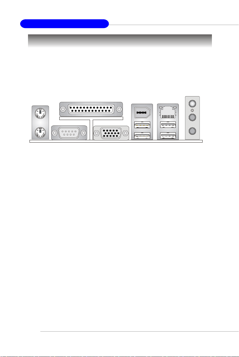
MS-7181 Micro-ATX Mainboard
Hinteres Anschlusspaneel
Ansicht Hinteres Anschlusspaneel
Das hintere Anschlusspaneel stellt die folgenden Anschlüsse zur Verfügung:
Maus
Tastatur
COM 1
Parallel
VGA Port
1394
Port
USB Ports
LAN
USB Ports
L-In
L-Out
MIKro
G-14
Page 88

Benutzerhandbuch
BIOS Setup
Nach dem Einschalten beginnt der Computer den POST (Power On Self Test Selbstüberprüfung nach Anschalten). Sobald die Meldung unten erscheint, drücken
Sie die Taste <Entf>(<Del>) um das Setup aufzurufen.
Wenn die Nachricht verschwindet, bevor Sie reagieren und Sie möchten immer
noch ins Setup, starten Sie das System neu, indem Sie es erst AUS- und danach
wieder ANSCHALTEN, oder die “RESET”-Taste am Gehäuse betätigen. Sie können
das System außerdem neu starten, indem Sie gleichzeitig die Tasten <Strg>,<Alt>
und <Entf> drücken (bei manchen Tastaturen <Ctrl>,<Alt> und <Del>).
Press DEL to enter SETUP
Selecting the First Boot Device
Sie können das Laufwerk, von dem zuerst versucht werden soll, das
Betriebssytem zu laden, auch ohne Aufruf des BIOS wählen, indem Sie <F11> drücken,
sobald die obige Meldung erscheint. Sie rufen damit das Bootmenü auf.
Es kann geschehen, dass die POST Meldungen so schnell durchlaufen, dass Sie
nicht rechtzeitig reagieren können. Sollte dies der Fall sein, führen Sie einen Neustart
durch und drücken Sie 2 bis 3 Sekunden später <F11>, um das Bootmenü, wie im
Folgenden dargestellt, aufzurufen.
Select First Boot Device
Floppy : 1st Floppy
IDE-0 : IBM-DTLA-307038
CDROM : ATAPI CD-ROM DRIVE 40X M
[Up/Dn] Select [RETURN] Boot [ESC] cancel
Das Bootmenü zeigt alle bootf ähigen Geräte an. W ählen Sie eines unter Verwendung der Pfeiltasten aus und drücken Sie die Eingabetaste (<Enter>), das System booted daraufhin von dem gewählten Gerät. Diese Auswahl ändert nicht die
Einstellungen im BIOS Setup Utility, so dass beim nächsten Hochfahren des Systems
erneut das dort ursprünglich festgelegte primäre Gerät zum Booten herangezogen
wird.
G-15
Page 89

MS-7181 Micro-ATX Mainboard
Steuer-tasten
<↑> Vorhergehender Menü punkt
<↓> Nächster Menüpunkt
<←> Ein Eintrag nach links
<→> Ein Eintrag nach rechts
<Eingaber> Auswahl eines Eintrages
<Esc> Menü verlassen oder Aufruf des Hauptmenü s aus
Untermenü
<+/Bild auf>Hochzählen eines Wertes oder Ändern
<-/Bild ab> Herunterzählen eines Wertes oder Änderns
<F7> Wählt Standardwerte für den stabilsten Betrieb
<F9> Wählt Standardwerte für den leistungsmaxim. Betrieb
<F10> Speichern aller Änderungen im CMOS u.Verlassen d. BIOS
Hilfe aufrufen
Nach dem Start des Setup Menüs erscheint zuerst das Hauptmenü.
Main Menu (Hauptmenü)
Das Hauptmenü listed Funktionen auf, die Sie ändern können. Sie können die Steuer
tasten ( ↑↓ ) verwenden, um einen Menüpunkt auszuwählen. Die Online-Beschreibung
des hervorgehobenen Menüpunktes erscheint am unteren Bildschirmrand.
Untermenüs
Wenn Sie an der linken Seite bestimmter Felder ein Dreieckssymbolf finden (wie rechts
dargestellt), bedeuted dies, dass Sie über das entsprechende Feld ein Untermenü mit
zusätzlichen Optionen aufrufen können. Durch die
Steuertasten ( --> ) können Sie ein Feld hervorheben
und durch Drücken der Eingabetaste <Enter> in das
Untermenü gelangen. Dort können Sie mit den
Steuertasten Werte eingeben und navigieren. Durch
Drücken von <Esc > kommen Sie zurück ins Hauptmenü.
Allgemeine Hilfe <F1>
Das BIOS Setup verfügt über eine Allgemeine Hilfe (General Help). Sie können diese aus
jedem Menü einfach durch Drücken der Taste <F1> aufrufen. Sie listet die Tasten und
Einstellungen zu dem hervorgehobenen Menüpunkt auf. Um die Hilfe zu verlassen, drücken
Sie <Esc>.
G-16
Page 90

Benutzerhandbuch
The Main Menu
Nachdem Sie das Phoenix-Award® BIOS CMOS Setup Utility, aufgerufen haben,
erscheint das Hauptmenü. Es weist elf Setup- Funktionen und zwei Arten das Menü
zu verlassen auf. Verwenden Sie die Pfeiltasten, um im Menü zu navigieren und
drücken Sie die Eingabetaste (<Enter>), um ein Untermenü aufzurufen.
Standard CMOS Features
In diesem Menü können Sie die Basiskonfiguration Ihres Systems anpassen, so z.B.
die Uhrzeit, das Datum usw.
Advanced BIOS Features
Verwenden Sie diesen Menüpunkt, um AWARD®- spezifische weitergehende
Einstellungen an Ihrem System vorzunehmen.
Advanced Chipset Features
Verwenden Sie dieses Menü, um die Werte in den Chipsatzregistern zu ändern und
die Leistungsfähigkeit Ihres Systems zu optimieren.
Integrated Peripherals
Verwenden Sie dieses Menü, um die Einstellungen für integrierte Peripheriegeräte
vorzunehmen.
Power Management Setup
Verwenden Sie dieses Menü , um die Einstellungen für die Stromsparfunktionen
vorzunehmen.
PNP/PCI Configurations
Dieser Eintrag erscheint, wenn Ihr System Plug and Play- Geräte am PCI-Bus
unterstützt.
H/W Monitor
Gibt den Status Ihrer CPU, der Lüfter und Warnung bezüglich des Gesamtzustands
Ihres Systems wieder.
G-17
Page 91

MS-7181 Micro-ATX Mainboard
Load Optimized Defaults
In diesem Menü können Sie die BIOS- Einstellungen laden, die die beste Systemleistung
erzielen. Die Stabilität kann beeinträchtigt sein.
BIOS Setting Password
Verwenden sie dieses Menü, um das Kennwort für den BIOS- Zugriff einzugeben.
Save & Exit Setup
Abspeichern der BIOS-Änderungen im CMOS und verlassen des BIOS.
Exit Without Saving
Verlassen des BIOS´ ohne Speicherung, vorgenommene Ä nderungen verfallen.
G-18
Page 92

Benutzerhandbuch
Integrated Peripherals
AC97 Controller
W ählen Sie [Enabled] (eingeschaltet), wenn Sie den AC97 Audiokontroller onboard
verwenden möchten. Schalten SIe den Kontroller au, wenn Sie eine Soundkarte zur
Audioausgabe verwenden möchten. Mögliche Einstellungen: [Enabled] (eingeschaltet)
oder [Disabled] (ausgeschaltet).
Onboard LAN Control
Hier nehmen Sie Einstellungen zum Intel LAN- Kontroller onboard vor. Mögliche
Einstellungen: [Enabled] (eingeschaltet) oder [Disabled] (ausgeschaltet).
Onboard LAN Option ROM
Hier wird festgelet ob das Options- ROM des LAN Chip onboard aufgerufen wird.
Mögliche Einstellungen: [Enabled] (eingeschaltet) oder [Disabled] (ausgeschaltet).
Onboard 1394 Controller
Hier nehmen Sie Einstellungen zur 1394- Lösung onboard vor. Mögliche Einstellungen:
[Enabled] (eingeschaltet) oder [Disabled] (ausgeschaltet).
USB Controller
W ählen Sie [Enabled] (eingeschaltet), falls Ihr System einen USB- Kontroller besitzt
und Sie USB- Geräte verwenden. Mögliche Einstellungen: [All Enabled] (alles an),
[All Disabled] (alles aus).
USB Device Legacy Support
Hier sollte die Einstellung [Enabled] (eingeschaltet) lauten, wenn Sie ein USB 1.1/2.0
Gerät mit einem Betriebssystem verwenden möchten, dass USB 1.1/2.0 nicht
unterstützt oder keine passenden Treiber aufweist, wie etwa bei DOS oder SCO
Unix. Die Einstellung sollte nur auf [Disabled] (ausgeschaltet) lauten, wenn Sie ein
beliebig anderes USB Gerät außer einer Maus verwenden. Mögliche Einstellungen:
[Enabled] (eingeschaltet) oder [Disabled] (ausgeschaltet).
G-19
Page 93

MS-7181 Micro-ATX Mainboard
IDE Devices Configuration
Drücken Sie die Eingabetaste <Enter>, um das folgende Untermenü aufzurufen:
OnChip SATA
Hier nehmen Sie Einstellungen zur integrierten SATA Lösung vor. Mögliche
Einstellungen: [Enabled] (eingeschaltet) oder [Disabled] (ausgeschaltet).
SATA Mode
Legt den Betriebsmodus für SATA Laufwerke fest. Mögliche Einstellungen: [RAID],
[IDE].
IDE DMA transfer access
Die Einstellung [Enabled] (eingeschaltet) öffnet die DMA Busmaster Funktion
und führt DMA unter DOS aus, was zu schnellerer Datenübertragung führt.
Mögliche Einstellungen: [Enabled] (eingeschaltet) oder [Disabled] (ausgeschaltet).
OnChip IDE Channel 0/1
Der integrierte Peripheriekontroller verfügt über eine IDE- Schnittstelle, die bis zu
zwei IDE Kanäle unterstützt. Die Auswahl [Enabled] aktiviert jeden Kanal für
getrennt. Mögliche Einstellungen: [Enabled] (eingeschaltet) oder [Disabled]
(ausgeschaltet).
G-20
Page 94

Benutzerhandbuch
PNP/PCI Configurations
Dieser Abschnitt beschreibt die Konfiguration des PCI-Bussystems und der PnP (Plug
& Play) Funktionalität. PCI (Personal Computer Interconnect) ist ein System, das Ein-
/Ausgabegeräten erlaubt mit Geschwindigkeiten zu operieren, die sich denen
annähern, mit welchen die CPU selbst mit ihren speziellen Komponenten kommuniziert.
Dieser Abschnitt enthält einige äußerst technische Bereiche und es wird dringend
empfohlen, daß nur erfahrene Anwender von den Werkseinstellung abweichen.
Primary Graphics Adapter
Legt fest welche Grafikkarte Sie zur primären Ausgabe verwenden. Die verfügbaren
Einstellung lauten:
[AGP] Das System initialisiert zuerste eine installierte AGP Karte, ist keine
[PCI Slot] Das System initialisiert zuerste eine installierte PCI Grafikkarte, ist
solche vorhanden, wir die PCI Grafikkarte initialisiert.
keine solche vorhanden, wir die AGP Grafikkarte initialisiert.
G-21
Page 95

MS-7181 Micro-ATX Mainboard
H/W Monitor
Dieser Abschnitt gibt den Zustand Ihrer CPU, der Lüfter und des generellen
Systemstatus, etc. wieder. Die Überwachungsfunktion ist nur verfügbar, wenn das
Motherboard über die notwendigen Hardwareüberwachungsmechanismen verfügt.
Cool’n’Quiet control
Wurde speziell für AMD Athlon Prozessoren entworfen, und stellt eine Funktion zur
Erfassung der CPU Temperatur bereit, um Ihre CPU vor Überhitzung durch hohe Last
zu bewahren. Mögliche Einstellungen: [Disabled] (ausgeschaltet), [Auto].
MSI weist darauf hin...
1. Um die Stabilität der Cool'n'Quiet Function sicher zu stellen, wird
empfohlen, immer ein Speichermodul in DIMM1 einzusetzen.
2. Um sicher zu stellen, dass
die Cool’n’Quiet Function
eingeschaltet ist und
ordnungsgemäß arbeitet, ist
folgendes sicher zu stellen:
- Starten Sie das BIOS und
wählen Sie H/W Monitor.
Dort finden Sie die
Cool’n’Quiet control,
stellen Sie diese auf “Auto.
”
- Starten Sie Windows,
wä hlen Sie [Start]->
[Einstellungen]->
[Sytemsteuerrung]->
[Energieverwaltung]. Rufen
Sie die Energie-
verwaltung auf, und wählen
Sie das Energieschema Minimaler Energieverbrauch.
G-22
Page 96

Benutzerhandbuch
Chassis Intrusion
Ist diese Option eingeschaltet, dann wird jedes Öffnen des Gehäuses aufgezeichnet
und eine Warnung ausgegeben. Um diese zu löschen, müssen Sie [Reset] wählen -
danach kehrt das System wieder zu [Enabled] zurück. Die möglichen Einstellungen
sind: [Enabled] (eingeschaltet), [Reset] (zurücksetzen), oder [Disabled]
(ausgeschaltet).
Smart CPU Fan
Das Mainboard verfügt über das Smart Fan System, welches automatisch die
Lüftergeschwindigkeit in Abhängigkeit von der Temperatur kontrollieren kann, um
diese in einem bestimmten Rahmen zu halten. Mögliche Einstellungen: [Disabled]
(ausgeschaltet),[40OC/104OF],[50OC/122OF],[60OC/144OF].
Smart Fan Tolerance
Hier können Sie einen Toleranzwert für die unter “Smart CPU Fan” den Lüftern
zugeordnete Temperaturspanne festlegen. Erreichen die Temperaturen den oberen
Schwellenwert (die Temperaturen gemäß “Smart CPU Fan” zuzüglich des
Toleranzwertes, den Sie hier festlegen), drehen sich die Lüfter zur Kühlung schneller.
Erreichen die aktuellen Temperaturen im entgegen gesetzten Fall den unteren
Schwellenwert (die eingestellte Temperatur abzüglich des Toleranzwertes), verringert
sich die Lüftergeschwindigkeit, um die Temperatur stabil zu halten.
PC Health Status
Drücken Sie die Eingabetaste <Enter>, um das folgende Untermenü aufzurufen:
System/CPU Temperature, System/CPU Fan Speed, CPU Vcore, +12V,
+3.3V, VCC (V), 5VSB
Diese Menüpunkte geben den aktuellen Status aller überwachten Hardware
Geräte und Komponenten wieder, so z.B. die Spannung der CPU, Temperaturen
und alle Lüftergeschwindigkeiten.
G-23
Page 97

MS-7181 Micro-ATX Mainboard
Load Optimized Defaults
Diese Option des Hauptmenüs ermöglicht es Ihnen, alle BIOS Einstellungen auf Werte
zurückzusetzen, die der Mainboardhersteller als Voreinstellungen ab Werk fest gelegt
hat, um einen optimalen Betrieb des Mainboards zu erzielen.
Nachdem Sie “Load Optimized Defaults” gewählt haben, erscheint die folgende
Meldung:
Wenn Sie Z (auf Grund des deutschen Tastaturlayouts statt Y) drücken, werden die
Voreinstellungen ab Werk für den optimalen Betrieb des Mainboards geladen.
BIOS Setting Password
Nach Auswahl dieser Funktion erscheint eine Meldung wie folgt:
Geben Sie das Passwort in einer Länge von bis zu 8 Zeichen ein und drücken Sie die
Eingabetaste<Enter>. Die Passworteingabe löscht jegliches zuvor eingerichtetes
Passwort aus dem CMOS Speicher. Sie werden aufgefordert, das Passwort zu
bestätigen. Geben Sie das Passwort erneut ein und drücken Sie die Eingabetaste
<Enter>. Sie können ebenso <Esc> drücken, um den Vorgang zu verwerfen und kein
Passwort einzugeben.
Um ein eingerichtetes Passwort zu löschen, drücken Sie einfach die Eingabetaste
<Enter>, wenn Sie aufgefordert werden ein Passwort einzugeben. Es erscheint eine
Meldung, die die Deaktivierung des Passwortschutzes bestätigt. Ist der
Passwortschutz deaktiviert, fährt das System hoch und Sie können das BIOS aufrufen,
ohne ein Passwort eingeben zu müssen.
Wurde ein Passwort eingerichtet, werden Sie jedesmal, wenn Sie versuchen das
BIOS aufzurufen zur Eingabe aufgefordert. Dies verhindert unbefugte Änderungen
and der Systemkonfiguration.
G-24
 Loading...