

Page 1
i
G52-S9161X2
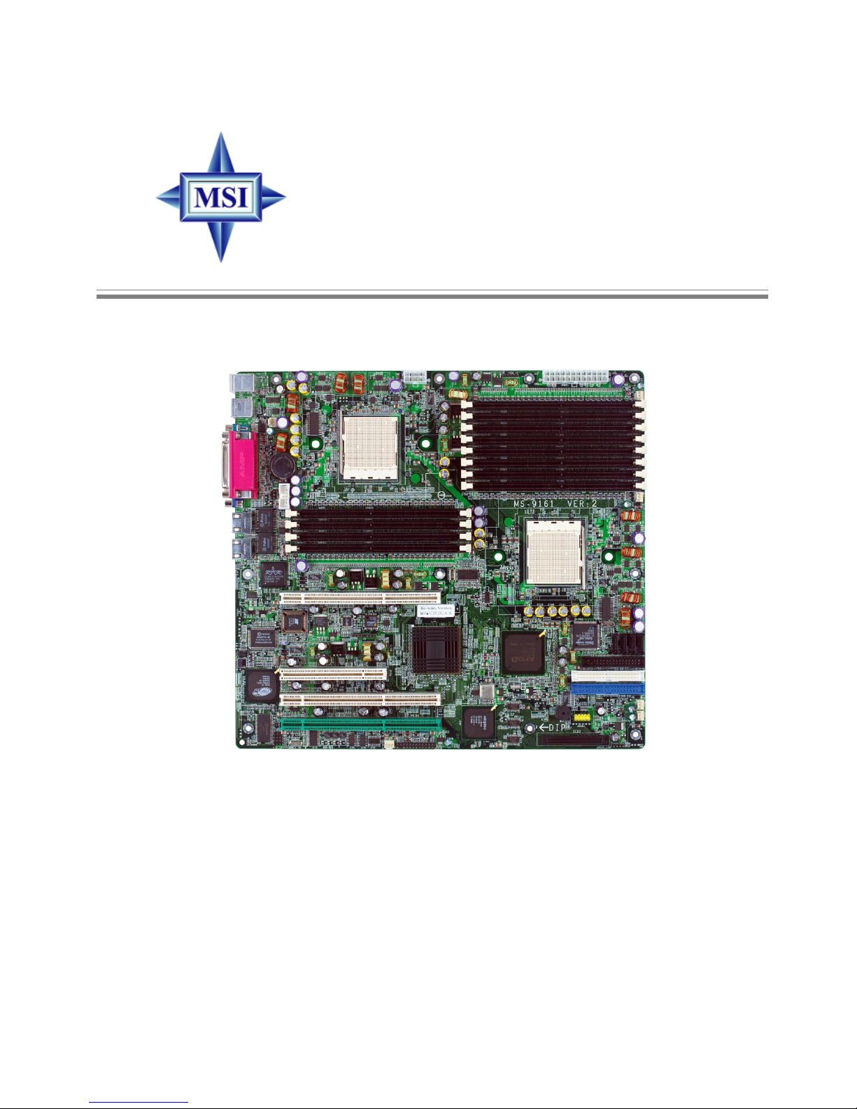
K8D Master3-133 Series
MS-9161 (v2.X) SSI Server Board
Page 2
ii
Manual Rev: 2.0
Release Date: July 2004
FCC-A Radio Frequency Interference Statement
This equipment has been tested and found to comply with the limits for a class A digital
device, pursuant to part 15 of the FCC rules. These limits are designed to provide
reasonable protection against harmful interference when the equipment is operated
in a commercial environment. This equipment generates, uses and can radiate radio
frequency energy and, if not installed and used in accordance with the instruction
manual, may cause harmful interference to radio communications. Operation of this
equipment in a residential area is likely to cause harmful interference, in which case
the user will be required to correct the interference at his own expense.
Notice 1
The changes or modifications not expressly approved by the party responsible for
compliance could void the user’s authority to operate the equipment.
Notice 2
Shielded interface cables and A.C. power cord, if any, must be used in order to
comply with the emission limits.
VOIR LA NOTICE D’INST ALLATION A V ANT DE RACCORDER AU RESEAU.
Micro-Star International
MS-9161
This device complies with Part 15 of the FCC Rules. Operation is subject to the
following two conditions:
(1) this device may not cause harmful interference, and
(2) this device must accept any interference received, including interference that
may cause undesired operation.
Page 3

iii
Copyright Notice
The material in this document is the intellectual property of MICRO-STAR
INTERNATIONAL. We take every care in the preparation of this document, but no
guarantee is given as to the correctness of its contents. Our products are under
continual improvement and we reserve the right to make changes without notice.
Trademarks
All trademarks are the properties of their respective owners.
AMD, Athlon™, Athlon™ XP, Thoroughbred™, and Duron™ are registered trademarks of AMD Corporation.
Intel® and Pentium® are registered trademarks of Intel Corporation.
PS/2 and OS®/2 are registered trademarks of International Business Machines
Corporation.
Windows® 95/98/2000/NT/XP are registered trademarks of Microsoft Corporation.
Netware® is a registered trademark of Novell, Inc.
Award® is a registered trademark of Phoenix Technologies Ltd.
AMI® is a registered trademark of American Megatrends Inc.
Revision History
Revision Revision History Date
V2.0 First release for PCB 2.X July 2004
Technical Support
If a problem arises with your system and no solution can be obtained from the user’s
manual, please contact your place of purchase or local distributor. Alternatively,
please try the following help resources for further guidance.
Visit the MSI website for FAQ, technical guide, BIOS updates, driver updates,
and other information: http://www.msi.com.tw/program/service/faq/
faq/esc_faq_list.php
Contact our technical staff at: support@msi.com.tw
Page 4

iv
Safety Instructions
CAUTION: Danger of explosion if battery is incorrectly replaced.
Replace only with the same or equivalent type recommended by the
manufacturer.
1. Always read the safety instructions carefully.
2. Keep this User’s Manual for future reference.
3. Keep this equipment away from humidity.
4. Lay this equipment on a reliable flat surface before setting it up.
5. The openings on the enclosure are for air convection hence protects the equipment from overheating. DO NOT COVER THE OPENINGS.
6. Make sure the voltage of the power source and adjust properly 110/220V before connecting the equipment to the power inlet.
7. Place the power cord such a way that people can not step on it. Do not place
anything over the power cord.
8. Always Unplug the Power Cord before inserting any add-on card or module.
9. All cautions and warnings on the equipment should be noted.
10. Never pour any liquid into the opening that could damage or cause electrical
shock.
11. If any of the following situations arises, get the equipment checked by a service
personnel:
h The power cord or plug is damaged.
h Liquid has penetrated into the equipment.
h The equipment has been exposed to moisture.
h The equipment has not work well or you can not get it work according to
User’s Manual.
h The equipment has dropped and damaged.
h The equipment has obvious sign of breakage.
12. DO NOT LEA VE THIS EQUIPMENT IN AN ENVIRONMENT UNCONDITIONED, STORAGE TEMPERA TURE ABOVE 600 C (1400F), IT MA Y DAMAGE THE EQUIPMENT .
Page 5

v
CONTENTS
FCC-A Radio Frequency Interference Statement ........................................................ ii
Copyright Notice........................................................................................................... iii
Trademarks ................................................................................................................... i ii
Revision History........................................................................................................... ii i
Technical Support ........................................................................................................ iii
Safety Instructions ...................................................................................................... iv
Chapter 1. Getting Started ...................................................................................1-1
Mainboard Specifications .................................................................................. 1-2
Mainboard Layout ..............................................................................................1-5
MSI Special Features .........................................................................................1-7
PC Alert™ III ................................................................................................1-7
Chapter 2. Hardware Setup .................................................................................2-1
Quick Components Guide...................................................................................2-2
Central Processing Unit: CPU............................................................................. 2-3
CPU Installation Procedures for Socket 940............................................. 2-4
Installing AMD OpteronTM DP CPU Cooling System...................................2-4
Memory ............................................................................................................... 2-6
Installing DDR Modules ............................................................................... 2-6
DIMM Configurations .................................................................................. 2-7
Memory Population Rules ........................................................................... 2-7
Power Supply.....................................................................................................2-8
SSI 24-Pin Power Connector: JPWR1 .......................................................2-8
SSI 8-Pin Power Connector: JPWR2.......................................................... 2-8
SSI 5-Pin Power Connector: J2 ................................................................. 2-8
Back Panel ..........................................................................................................2-9
Connectors .......................................................................................................2-10
Floppy Disk Drive Connector: FDD1 .........................................................2-10
Hard Disk Connectors: IDE1 & IDE2 .........................................................2-10
Serial ATA RAID 0, 1, 10 Connectors: SATA1/2/3/4 (Optional) .............. 2-11
LCD Panel Connector: JLCD1...................................................................2-12
Fan Power Connectors: CFAN1/2, SFAN1/2, PFAN1/2..........................2-12
Ultra320 SCSI Connector: SCSI (Optional).............................................2-13
SCSI LED Connector: JSCSI_LED (Optional) ..........................................2-13
Front USB Connector: JUSB1..................................................................2-14
Front Panel Connector: JSSI1..................................................................2-14
System Status LED Header: J11 ..............................................................2-15
Page 6

vi
I2C Bus Connector: I2CCON1 ..................................................................2-15
Serial Port Connector: COM 2..................................................................2-15
System ID Button: J5 ................................................................................ 2-16
System ID LED: D38 ..................................................................................2-16
System ID LED Connector: J10 ................................................................ 2-16
System ID Button Connector: J9 .............................................................. 2-16
Jumpers ............................................................................................................2-17
Clear CMOS Jumper: JBAT1 ....................................................................2-17
PCIX Channel A Frequency Jumper: J25.................................................2-18
PCIX Channel B Frequency Jumper: J4 .................................................. 2-18
Server Management Jumper: JBMC1 ......................................................2-18
Slots ..................................................................................................................2-19
PCI (Peripheral Component Interconnect) Slots......................................2-19
PCI Interrupt Request Routing..................................................................2-20
Chapter 3. BIOS Setup ........................................................................................... 3-1
Entering Setup .................................................................................................... 3-2
Control Keys ............................................................................................... 3-2
Getting Help ................................................................................................ 3-3
General Help <F1>...................................................................................... 3-3
The Menu Bar .....................................................................................................3-4
The Main Menu ................................................................................................... 3-5
The Advanced Menu ..........................................................................................3-7
The Security Menu ...........................................................................................3-18
The Power Menu ..............................................................................................3-20
The Boot Menu ................................................................................................. 3-22
The Exit Menu ...................................................................................................3-23
Appendix A: SCSI BIOS Setup (Optional) ......................................................... A-1
Entering SCSI BIOS ........................................................................................... A-2
Control Keys .............................................................................................. A-2
Selecting the SCSI Channel ...................................................................... A-2
Selecting the Management Type............................................................... A-2
Configure/View SCSI Controller Settings ........................................................ A-4
SCSI Bus Interface Definitions .................................................................. A-4
Additional Options ..................................................................................... A-5
BIOS Information........................................................................................ A-8
Disk Utilities ........................................................................................................ A-8
Page 7

1-1
Getting Started
Chapter 1. Getting
Started
Getting Started
Thank you for purchasing the K8D Master3-133 Series (MS-
9161), an excellent Server System Infrastructure (SSI) mainboard
from MSI.
Based on the innovative AMD-8131 PCI-X Tunnel and AMD-
8111 I/O HUB chipsets for optimal system efficiency, K8D Master3133 Series SSI mainboards accommodate dual latest AMD Opteron
TM
DP processors in the 940-pin lidded ceramic micro PGA package, and
supports up to twelve 144-bit DDR registered ECC DIMMs (at 200,
266, 333, and 400 MHz) to provide the maximum of 24GB memory
capacity.
In the entry-level and mid-range market segment, this mainboard
can provide a high-performance solution for today’s front-end and
general purpose server/workstation, as well as in the future.
Page 8

1-2
MS-9161 SSI Server Board
Mainboard Specifications
Target Market Segment
h Target in the entry-level and mid-range, front-end and general purpose server
market segments
CPU
h Supports dual Socket 940 for AMD OpteronTM 200/100 Series processors
h AMD x86-64 Technology
- AMD’s 64-bit, x86 instruction set extensions
- 64-bit integer registers, 48-bit virtual address, 40-bit physical address
- Eight new 64-bit integer registers
- Eight new 128-bit SSE/SSE2 registers
Chipset
h AMD-8131 HyperTransport PCI-X Tunnel
- HyperTransportTM technology tunnel with side A (16 bits) and side B (8 bits)
- Each side supports transfer rates of 1600, 1200, 800, and 400 mega- transfer
per second
- Two PCI-X bridges: bridge A and bridge B (64-bit data bus)
- 133/100/66 MHz in PCI-X mode and 66/33 MHz in PCI mode
h AMD-8111 HyperTransport I/O Hub
- HyperTransportTM I/O Hub (supports up to 800 megebytes per second with 200
MHz clock)
- A 33 MHz/32-bit PCI 2.2 compliant bus interface supports up to eight external
devices
- LPC bus to connect peripheral such as super I/O and BIOS
- Extensive ACPI-compliant power management
- IO APCI controller
- AC’97 2.2 soft audio controller
- USB hosts supporting USB 1.1 ports
Main Memory
h 144-bit DDR at 200/266/333/400 MHz
h Supports twelve 184-pin DDR DIMMs up to 24GB
h Supports interleaving memory within DIMMs
h ChipKill ECC allows continuous correction of 4-bit errors in a failed x 4 memory
device
Slots
h Three 64-bit, 66/100/133 MHz PCI-X slots
h One 32-bit, 33 MHz PCI slot
HDD Interface
h K8D Master3-133-FS:
- SCSI interface supported by Adaptec AIC-7901 Ultra-320 SCSI controller
- Ultra ATA/100 Bus Master IDE interface supported by AMD-8111 HyperTransport
I/O Hub (with 2 IDE connectors onboard/can connect up to 4 Ultra ATA drives)
Page 9

1-3
Getting Started
h K8D Master3-133-F A4R:
- Serial ATA RAID interface supported by Silicon Image SiI 3114 PCI to four-port
Serial ATA host controller (with 4 SATA connectors onboard/can connect up to 4
Serial ATA drives)
- Ultra ATA/100 Bus Master IDE interface supported by AMD-8111 HyperTransport
I/O Hub (with 2 IDE connectors onboard/can connect up to 4 Ultra ATA drives)
Onboard Peripherals
h One floppy port supports two FDDs with 360KB, 720KB, 1.2MB, 1.44MB, and 2.
88MB
h One PS/2 keyboard port
h One PS/2 mouse port
h Two serial ports (COM1 serial port + COM2 serial header)
h One parallel port supports SPP/EPP/ECP mode
h Two RJ-45 ports (with LEDs)
h Four USB ports (two on front and two on rear)
h One VGA port
Server Management (Optional)
h National Semiconductor® PC87431 mBMC (mini-Baseboard Management Controller)
- Incorporates an embedded microcontroller, three System Management Bus
(SMBus®) interfaces, a Chassis Management interface, Bi-color LED control, an
integrated EEPROM, Fan control, 12 ADC channels, and Digital Input Event and
General-Purpose Input/Output pins.
- Interfaces with the host via a slave SMBus interface; it interfaces with the LAN
On Motherboard (LOM) and with peripherals via two independent master SMBus
interfaces.
Networking
h Broadcom BCM5704 LAN controller
- Provides 1000/100/10 MB per second data rates, 64-bit/100 MHz PCI-X bus
- Dual ports
Power Management Features
h Wake up on LAN (WOL), wake up on serial ring, wake up on PCI
h RTC alarm and wake up
h Wake up on keyboard/ mouse/USB from S1
h Supports ACPI S1, S4, S5 function
System Management
h SMBus (I2C)
h Temperature, voltage, and fan monitors
h Chassis intrusion
BIOS
h 4 Mb flash EEPROM
h PCI 2.2 compliant, VPD, and DMI
h PnP 1.0A, SMBIOS 2.3, ACPI 1.0A/2.0
h Supports PXE boot protocol
h APM 1.2, WOL
h PC2001 system design compliant
Page 10
1-4
MS-9161 SSI Server Board
MSI Reminds You...
Please refer to Table 1 for 2D modes supporting both CRT and LCD.
The table specifies the minimum memory requirements for various
display resolutions, refresh rates and color depths.
Dimension
h SSI EEB 3.0 Form Factor: 12.0 x 13.0 inch
Mounting
h Twenty-one mounting holes (SSI standard)
Video
h Integrated ATI Rage™ XL graphics controller
- Built-in DVD decoding
- Integrated TMDS transmitter with support for Digital Flat Panel (DFP) monitors
- Onboard 8MB Video SDRAM
Mode Refresh Minimum Amount of Memory Required
rate(Hz)
640x480 60
640X480 7 2
640X480 7 5
640X480 9 0
640X480 100
800X600 6 0
800X600 7 0
800X600 7 5
800X600 9 0
800X600 100
1024X768 6 0
1024X768 7 2
1024X768 7 5
1024X768 9 0
1024X768 100
1280x1024 43
1280x1024 60
1280x1024 70
1280x1024 72
1600x1200 66
1600x1200 76
8bpp 16bpp 24bpp 32bpp
2MB 2MB 2MB 2MB
2MB 2MB 2MB 2MB
2MB 2MB 2MB 2MB
2MB 2MB 2MB 2MB
2MB 2MB 2MB 2MB
2MB 2MB 2MB 4MB
2MB 2MB 2MB 4MB
2MB 2MB 2MB 4MB
2MB 2MB 2MB 4MB
2MB 2MB 2MB 4MB
2MB 2MB 4MB 4MB
2MB 2MB 4MB 4MB
2MB 2MB 4MB 4MB
2MB 2MB 4MB 4MB
2MB 2MB 4MB 4MB
2MB 4MB 4MB 6MB
2MB 4MB 4MB 6MB
2MB - 4MB 6MB
2MB - 4MB 6MB
4MB 4MB 6MB 8MB
4MB 4MB 6MB -
Table 1. 2D Modes (TFT or CRT)
Shading indicates modes not supported by TFT
Page 11
1-5
Getting Started
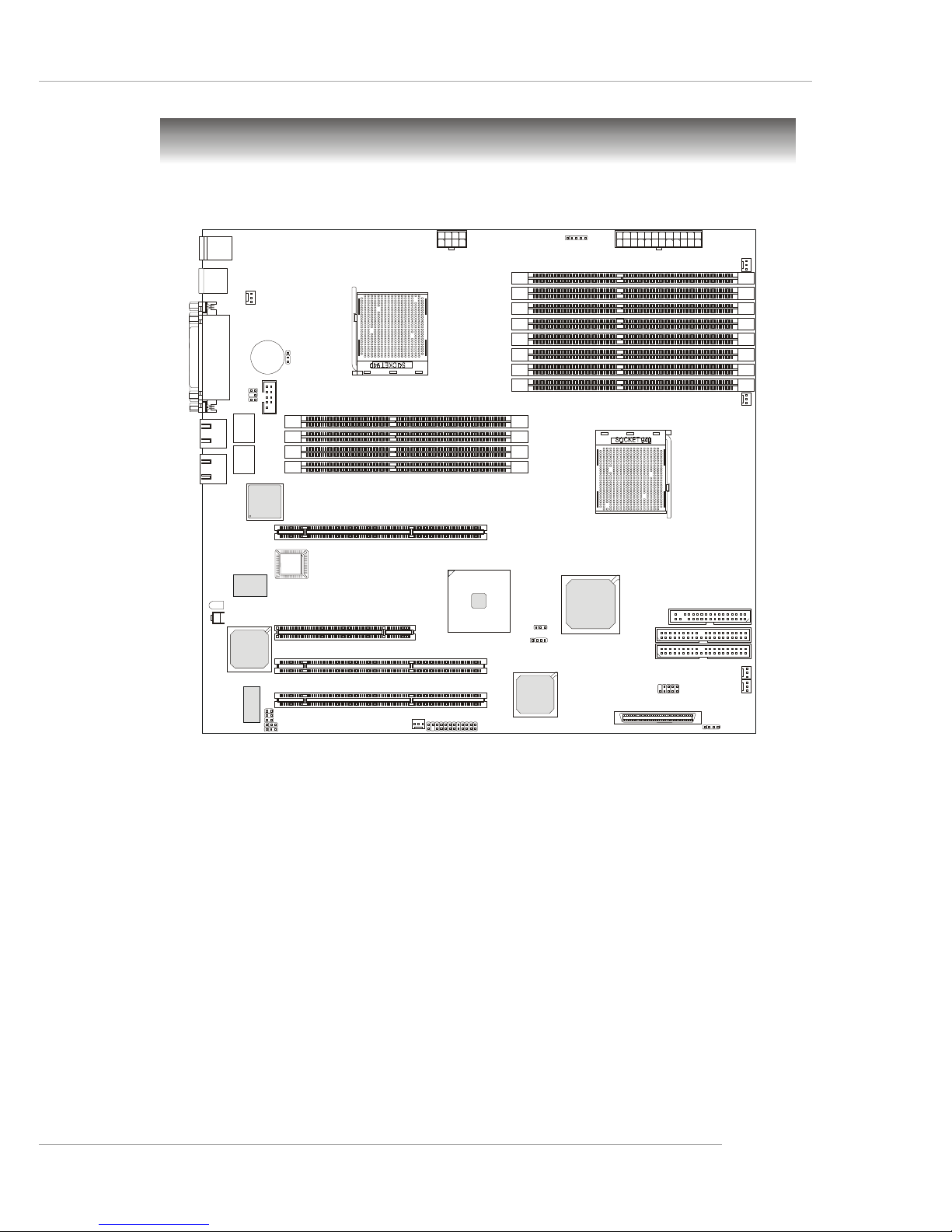
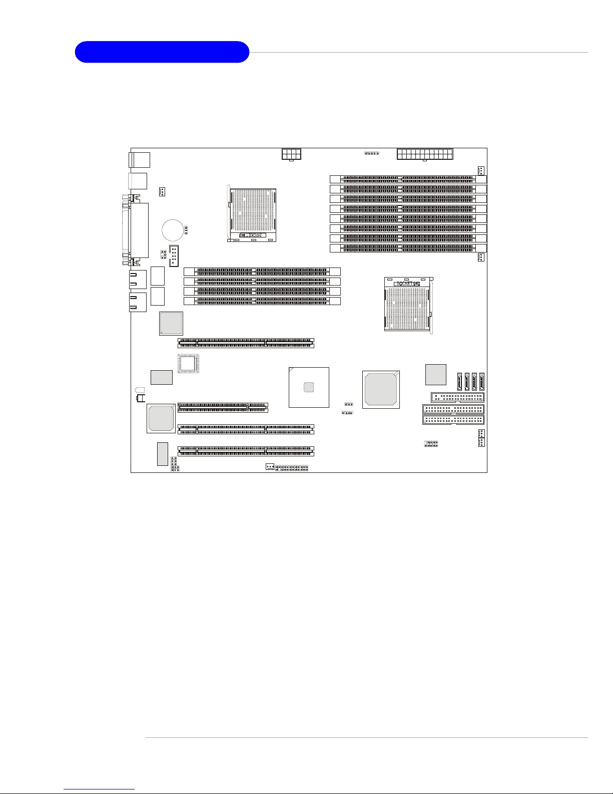
Mainboard Layout
K8D Master3-133-FS (MS-9161 v2.X) SSI Server Board
- SCSI interface supported by Adaptec AIC-7901 Ultra-320 SCSI controller
AMD-8111
AMD-8131
Adaptec
AIC-7901X
RAGE XL
DDR1
DDR3
DDR5
DDR12
DDR7
DDR10
DDR2
DDR4
DDR6
DDR11
DDR8
DDR9
B
I
O
S
PCI X1
PCI X2
PCI X3
PCI 2
IDE2
IDE1
USB
Top: Port 1
Bott om: P ort 2
Top:
Parallel Port
Bottom:
COM Port
VGA Port
To: Mous e
Bottom: Keyboard
CFAN1
PFAN1
CFAN2
SFAN1
SFAN2
PFAN2
COM 2
JBAT1
SCSI
JPWR1JPWR2
FDD1
JUSB1
JSSI1
J4
JSCSI_LED
J2
BATT
+
LAN
LAN
Winbond
W986432DH-6
Winbond
W83627HF-AW
BROADCOM
BCM5704C
J5
D38
Pulse
H5007
Pulse
H5007
JLCD1
J9
J10
J11
I2CCON1
JBMC1
J25
Page 12
1-6
MS-9161 SSI Server Board
K8D Master3-133-FA4R (MS-9161 v2.X) SSI Server Board
- Serial ATA RAID interface supported by Silicon Image SiI 3114
PCI to four-port Serial ATA host controller
AMD-8111
AMD-8131
RAGE XL
DDR1
DDR3
DDR5
DDR12
DDR7
DDR10
DDR2
DDR4
DDR6
DDR11
DDR8
DDR9
B
I
O
S
PCI X1
PCI X2
PCI X3
PCI 2
IDE2
IDE1
USB
Top: Port 1
Bottom: Port 2
Top:
Parallel Port
Bottom:
COM Port
VGA Port
To: Mous e
Bottom: Keyboard
CFAN1
PFAN1
CFAN2
SFAN1
SFAN2
PFAN2
COM 2
JBAT1
JPWR1JPWR2
FDD1
JUSB1
JSSI1
S
A
T
A
1
S
A
T
A
2
S
A
T
A
3
S
A
T
A
4
J4
J2
BATT
+
LAN
LAN
Winbond
W986432DH-6
Winbond
W83627HF-AW
BROADCOM
BCM5704C
Silicon Image
Sil3114
J5
D38
Pulse
H5007
Pulse
H5007
JLCD1
J9
J10
J11
I2CCON1
JBMC1
J25
Page 13
1-7
Getting Started
MSI Special Features
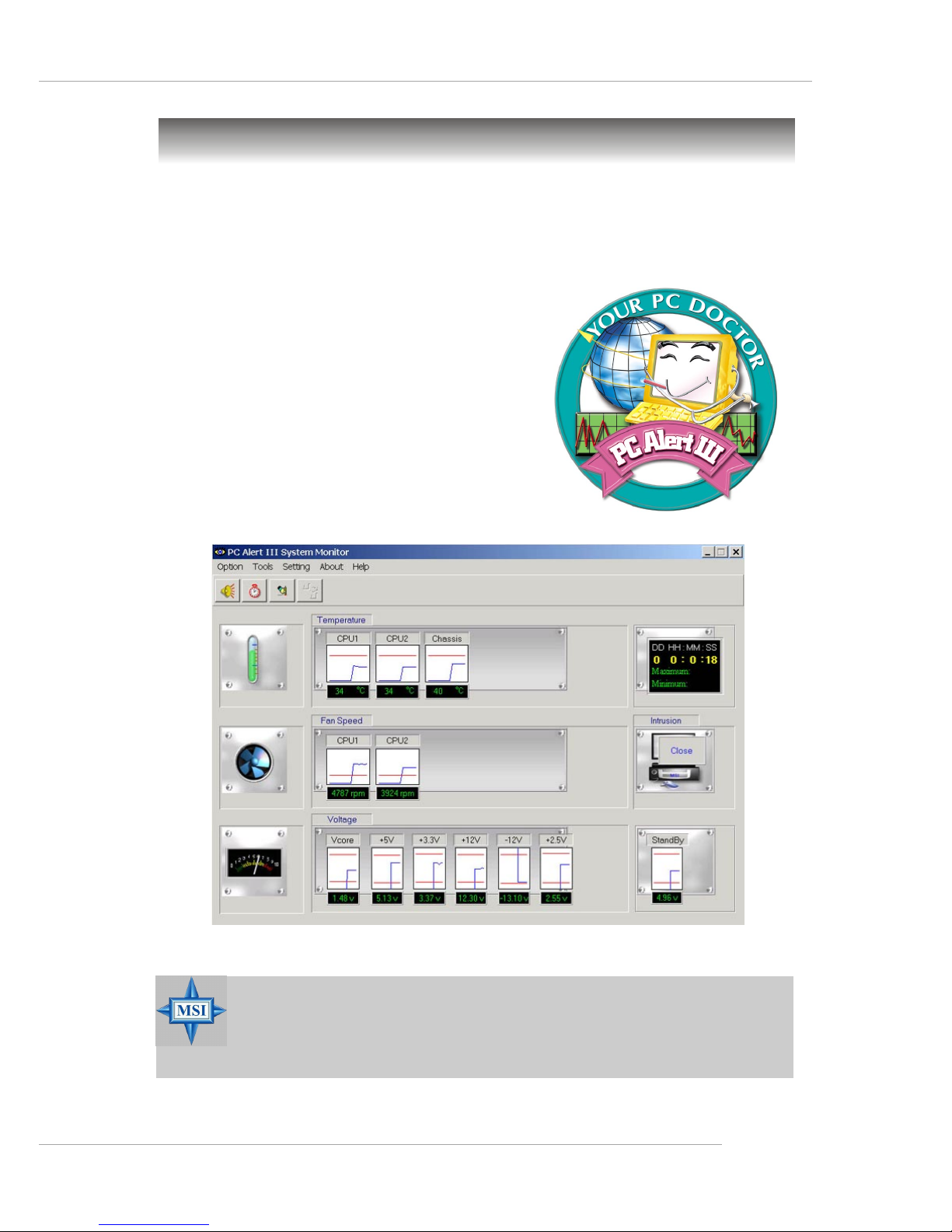
PC Alert™ III
The PC AlertTM III is a utility you can find in the CD-ROM disk. The utility is just like
your PC doctor that can detect the following PC
hardware status during real time operation:
Ø monitor CPU & system temperatures
Ø monitor fan speed(s)
Ø monitor system voltage
Ø monitor chassis intrusion
If one of the items above is abnormal, the
program main screen will be immediately shown
on the screen, with the abnormal item highlighted
in red. This will continue to be shown until user
disables the warning.
MSI Reminds You...
1. Items shown on PC Alert™ III vary depending on your system status.
2. The mainboard bound with mBMC chip (Server Management
Features) WON’T support PC Alert™ III.
Page 14

2-1
Hardware Setup
Chapter 2. Hardware
Setup
Hardware Setup
This chapter provides you with the information about hardware setup procedures. While doing the installation, be careful in
holding the components and follow the installation procedures. For
some components, if you install in the wrong orientation, the components will not work properly.
Use a grounded wrist strap before handling computer
components. Static electricity may damage the components.
Page 15
2-2
MS-9161 SSI Server Board
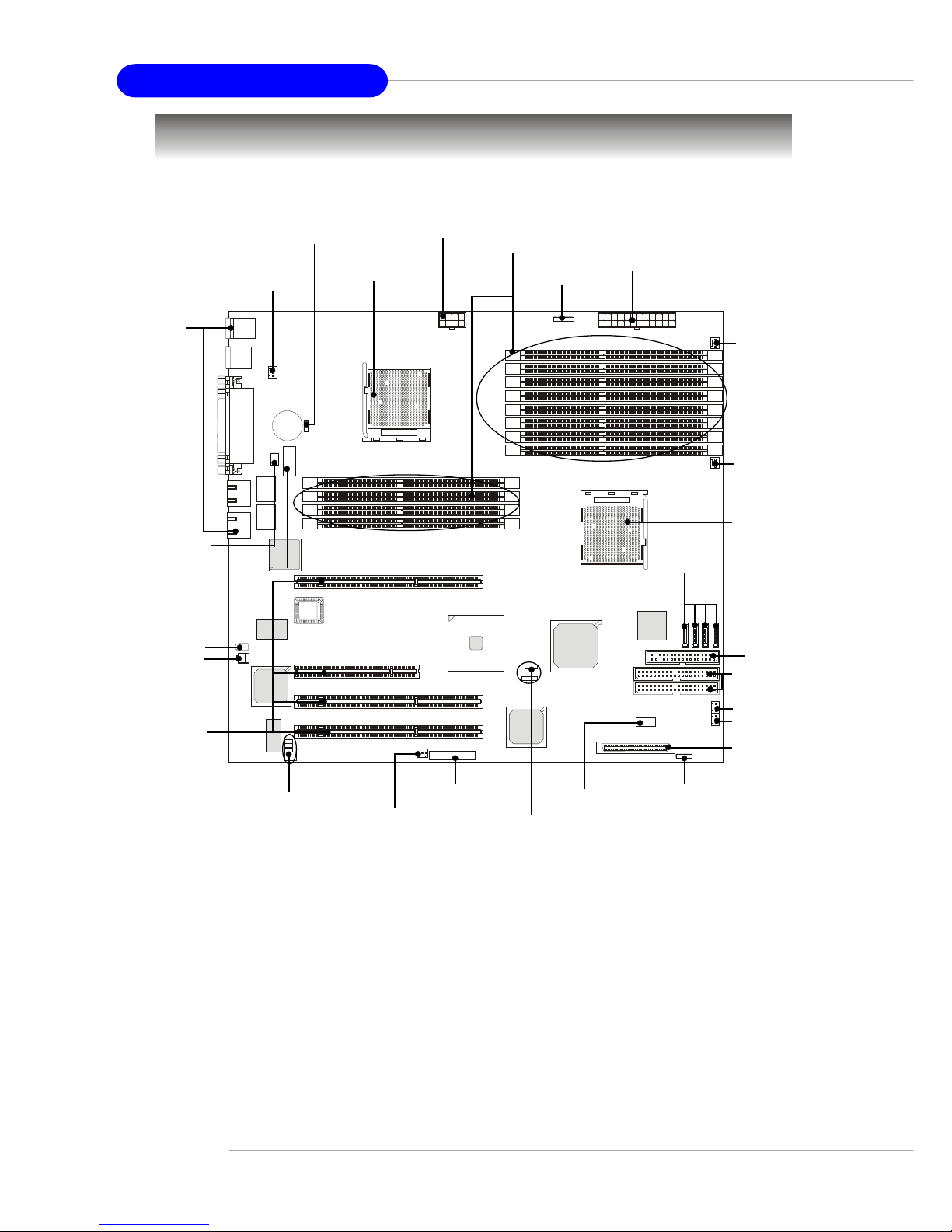
Quick Components Guide
CPU2, p.2-3
JPWR2, p.2-8
I/O Ports,
p.2-9
JLCD1, p.2-12
COM2, p.2-15
DDR DIMMs, p.2-6
CFAN1, p.2-12
CFAN2, p.2-12
PFAN1, p.2-12
CPU1, p.2-3
J2, p.2-8
JPWR1, p.2-8
IDE2/1, p.2-10
SFAN1, p.2-12
JBAT1, p.2-17
JSSI1, p.2-14
FDD1, p.2-10
JUSB1, p.2-14
SFAN2, p.2-12
PCI Slots,
p.2-19
SCSI, p.2-13
JSCSI_LED, p.2-13
J4/J25, p.2-18
SATA4/3/2/1, p.2-11
J9/
J10, p.2-16
J11/
I2CCON1, p.2-15
JBMC1, p.2-18
PFAN1, p.2-12
D38, p.2-16
J5, p.2-16
Page 16
2-3
Hardware Setup
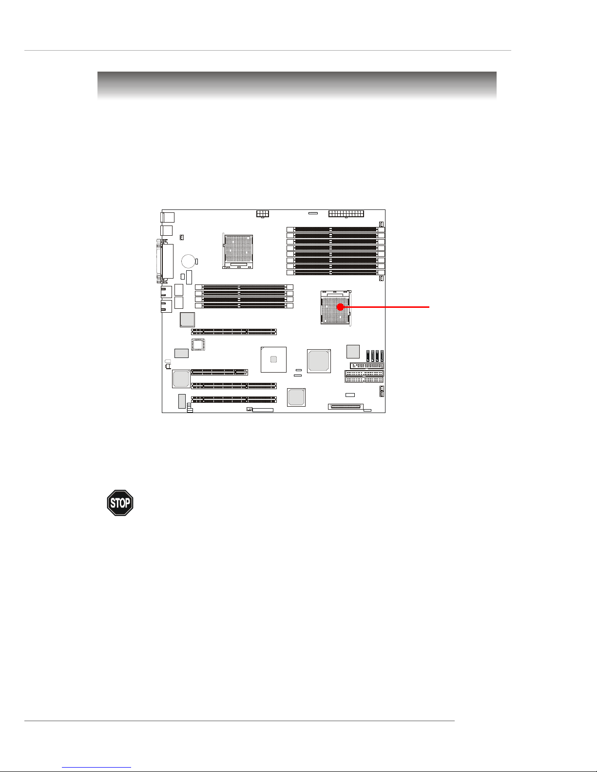
The mainboard supports Single/Dual AMD® Opteron™ DP processor(s). The
mainboard uses two CPU sockets called Socket 940 for easy CPU installation. You
can install SINGLE or DUAL CPUs on the mainboard to meet your own needs. Keep
the following points in mind before installing CPU(s):
1. If SINGLE CPU is intended, always install the CPU on the CPU1 socket.
2. To install DUAL CPUs on the board, you must use the same type of CPUs
running at the same frequency.
Central Processing Unit: CPU
As processor technology pushes to faster speeds and higher performance,
thermal management becomes increasingly crucial when building computer systems.
Maintaining the proper thermal environment is key to reliable operation. As such, the
processor must be maintained in the specified thermal requirements.
WARNING!
Thermal Issue for CPU
CPU1
Page 17
2-4
MS-9161 SSI Server Board
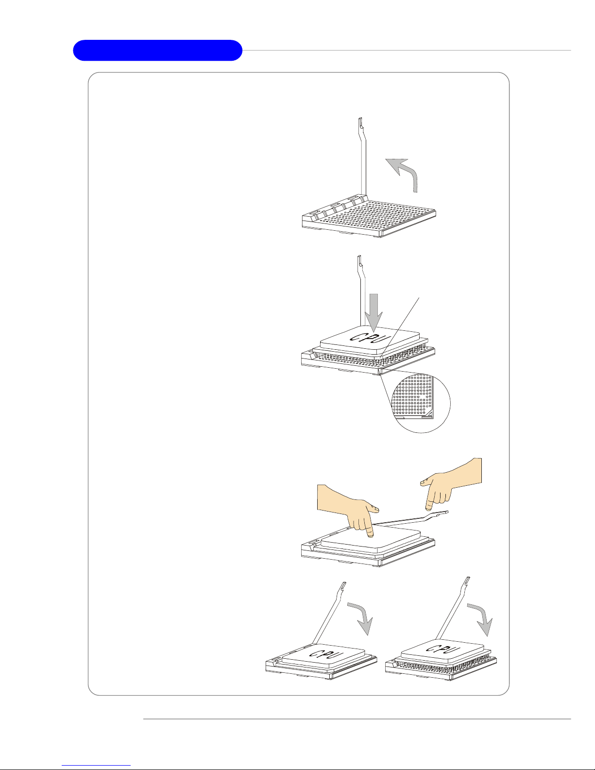
1. Make sure that the computer is
turned off, and the power cord disconnected before installing the CPU.
2. Pull the lever sideways away
from the socket, and raise it up to a
90-degree angle.
3. Locate the cut edge of the CPU.
When the CPU is installed into the
socket, this cut edge should be
aligned with the corner marking an
arrow on the Socket 940.
Please note that the CPU can only fit
in a correct orientation, DO NOT use
force to install the CPU into the
socket.
4. Place the CPU onto the socket and
press it down firmly into the socket.
The pins of the CPU should be embedded into the socket completely.
5. Close the lever to secure the CPU.
Do not close the lever until the CPU’s
pins are fully inserted; otherwise,
the pins may be damaged.
CPU Installation Procedures for Socket 940
XO
Open Lever
S
l
i
d
i
n
g
P
l
a
t
e
Close
Lever
Press down
the CPU
Cut edge
Corner marking
an arrow
Page 18
2-5
Hardware Setup
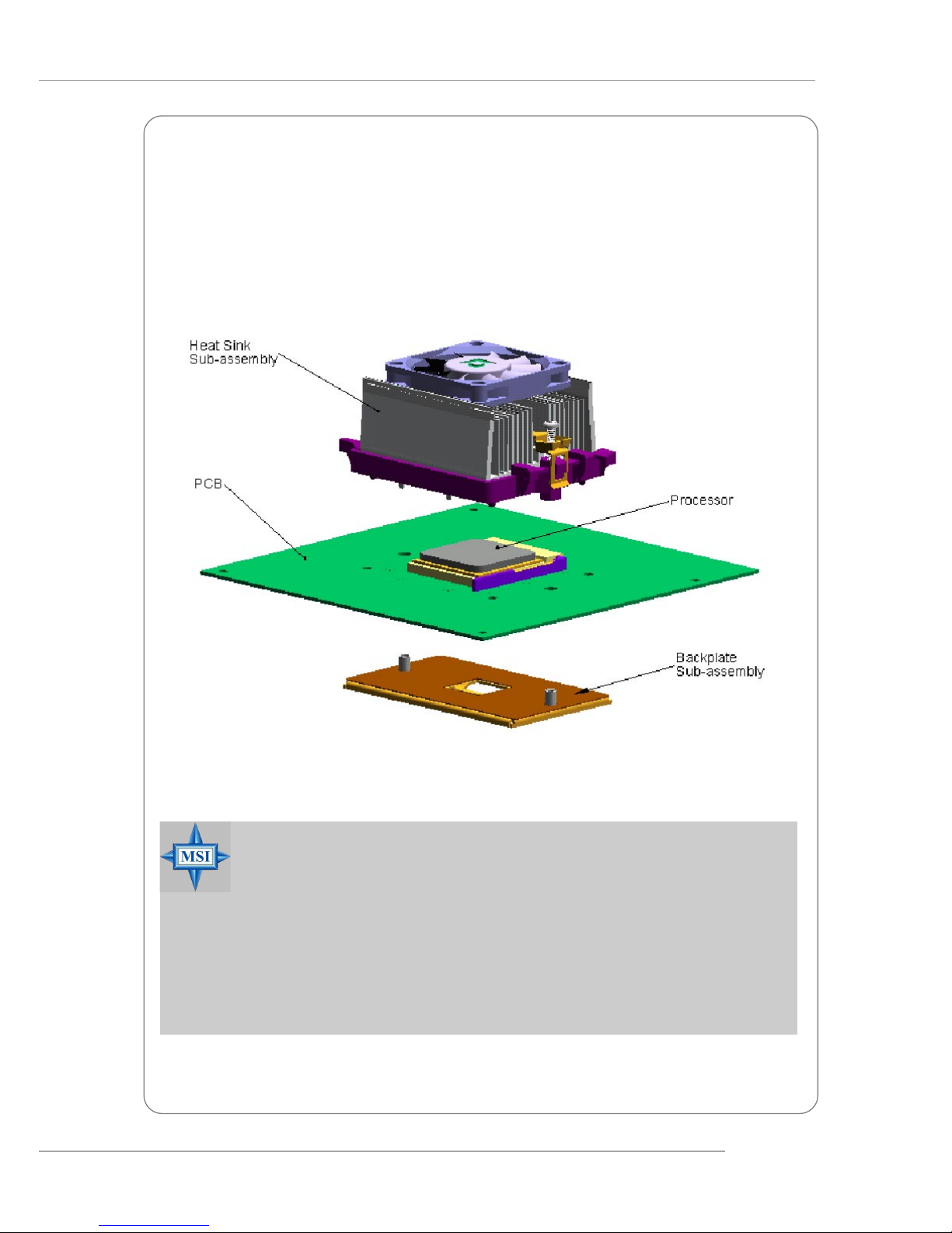
Installing AMD OpteronTM DP CPU Cooling System
When you are installing the CPU, make sure the CPU has a heat sink and
a cooling fan attached on the top to prevent overheating. If you do not find the
heat sink and cooling fan, contact your dealer to purchase and install them before
turning on the computer.
reference figure
MSI Reminds You...
Overheating
Overheating will seriously damage the CPU and system, always make
sure the cooling fan can work properly to protect the CPU from
overheating.
Replacing the CPU
While replacing the CPU, always turn off the power supply or unplug
the power supply’s power cord from grounded outlet first to ensure the
safety of CPU.
Page 19
2-6
MS-9161 SSI Server Board
Memory
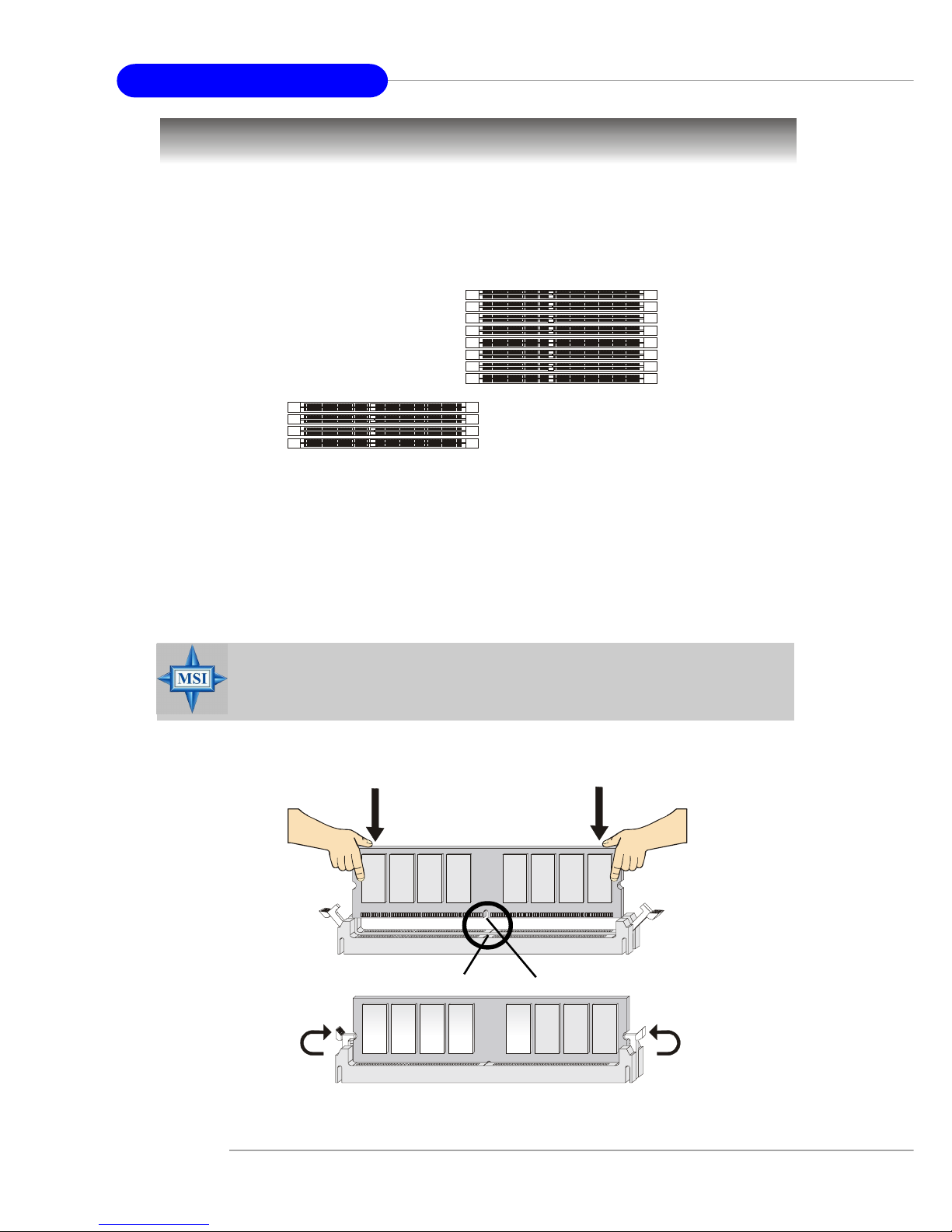
Installing DDR Modules
1. The DDR DIMM has only one notch on the center of module. The module will only fit
in the right orientation.
2. Insert the DIMM memory module vertically into the DIMM slot. Then push it in until the
golden finger on the memory module is deeply inserted in the socket.
3. The plastic clip at each side of the DIMM slot will automatically close.
The mainboard provides 12 slots for 184-pin DDR SDRAM DIMM
(Double In-Line Memory Module) modules and supports up to 24GB memory size. You
can install DDR266/333/400 modules on the DDR DIMM slots (DIMM 1~12).
DDR8
DDR7
DDR6
DDR5
DDR4
DDR3
DDR2
DDR1
DDR9
DDR10
DDR11
DDR12
MSI Reminds You...
You can barely see the golden finger if the module is properly inserted
in the socket.
Volt
Notch
Page 20
2-7
Hardware Setup
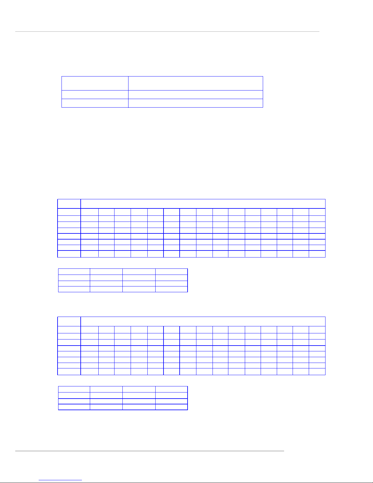
DIMM Configurations
Supported DIMM 100MHz 133MHz 166MHz 200MHz
Configurations DDR200 DDR266 DDR333 DDR400
64-bit plus ECC 4422
128-bit plus ECC 8844
Memory Population Rules
The mainboard supports DDR200/266/333/400 memory interface.
Each DIMM slot supports up to a maximum size of 2GB. Users can install either
single- or double-sided modules depending on their needs.
Memory modules can be installed in any combination as follows:
Slot Memory module population rules (Dual channel - 128 bits)
DDR 1 Install Install Install Install Install Install Install Install
DDR 2 Install Install Install Install Install Install Install Install
DDR 3 Install Install Install Install Install Install Install Install
DDR 4 Install Install Install Install Install Install Install Install
DDR 5 Install Install Install Install Install Install Install Install
DDR 6 Install Install Install Install Install Install Install Install
DDR 7 Install Install Install Install Install Install Install Install
DDR 8 Install Install Install Install Install Install Install Install
DDR9 Install Install
DDR10 Install Install
DDR11 Install Install
DDR12 Install Install
Slot Memory module population rules (Single channel - 64 bits)
DDR 1
DDR 2 Install Install Install Install Install Install Install Install
DDR 3
DDR 4 Install Install Install Install Install Install Install Install
DDR 5
DDR 6 Install Install Install Install Install Install Install Install
DDR 7
DDR 8 Install Install Install Install Install Install Install Install
DDR9
DDR10 Install Install
DDR11
DDR12 Install Install
Page 21

2-8
MS-9161 SSI Server Board
Power Supply
The mainboard supports SSI power supply for the power system. Before
inserting the power supply connector, always make sure that all components are
installed properly to ensure that no damage will be caused.
SSI 24-Pin Power Connector: JPWR1
This connector allows you to connect to an SSI power supply. To connect to
the SSI power supply, make sure the plug of the power supply is inserted in the
proper orientation and the pins are aligned. Then push down the power supply firmly
into the connector.
SSI 8-Pin Power Connector: JPWR2
This connector provides 12V power output to the CPU.
SSI 5-Pin Power Connector: J2
This connector provides power supply to the System Management Bus (SMB).
PIN SIGNAL
13 +3.3V
14 -12V
15 GND
16 PS-ON#
17 GND
18 GND
19 GND
20 3VSB
21 +5V
22 +5V
23 +5V
24 GND
PIN SIGNAL
1 +3.3V
2 +3.3V
3 GND
4 +5V
5 GND
6 +5V
7 GND
8 PWR OK
9 5VSB
10 +12V
11 +12V
12 +3.3V
JPWR1 Pin Definition
PIN SIGNAL
5 +12V
6 +12V
7 +12V
8 +12V
PIN SIGNAL
1 GND
2 GND
3 GND
4 GND
JPWR2 Pin Definition
MSI Reminds You...
Power supply of 425watt (and up) is highly recommended for system
stability.
J2
1
PIN SIGNAL
1 SMB clock
2 SMB data
3 PS alert
4 GND
5 3.3RS
J2 Pin Definition
JPWR1
12
1
24
13
JPWR2
1
8
5
4
Page 22

2-9
Hardware Setup
Back Panel
RJ-45 LAN Jack
Link Indicator
8 1
Activity Indicator
Gigabit LAN Pin Definition
USB Ports
1 2 3 4
Serial Port
PIN SIGNAL
1DCD
2 SIN
3 SOUT
4 DTR
5 GND
6 DSR
7 RTS
8 CTS
9RI
VGA Port
Mouse/Keyboard Connector
Pin1
Mouse/KBD
DATA
Pin2 NC
Pin3 GNDPin4 VCC
Pin5
Mouse/KBD Clock
Pin6 NC
PIN SIGNAL
1 RED
2 GREEN
3 BLUE
4 N/C
5 GND
6 GND
7 GND
8 GND
9 +5V
10 GND
1 1 N/C
12 SDA
13 Horizontal Sync
14 Vertical Sync
15 SCL
1 2 3 4 5
6 7 8 9
1
5
11
15
PIN SIGNAL
1 VCC
2 -Data
3 +Data
4 GND
PIN SIGNAL DESCRIPTION
1 D0P Differential Pair 0+
2 D0N Differential Pair 03 D1P Differential Pair 1+
4 D2P Differential Pair 2+
5 D2N Differential Pair 26 D1N Differential Pair 17 D3P Differential Pair 3+
8 D3N Differential Pair 3-
VGAUSBKeyboard COM1 LANLAN
Parallel
Mouse
Page 23

2-10
MS-9161 SSI Server Board
The mainboard provides connectors to connect to FDD, IDE HDD, case, LAN,
USB Ports, CPU/system power supply fans, ... and etc.
Floppy Disk Drive Connector: FDD1
The mainboard provides a standard floppy disk drive connector that supports
360K, 720K, 1.2M, 1.44M and 2.88M floppy disk types.
Connectors
FDD1
MSI Reminds You...
If you install two hard disks on cable, you must configure the second
drive to Slave mode by setting its jumper. Refer to the hard disk documentation supplied by hard disk vendors for jumper setting instructions.
IDE1 (Primary IDE Connector)
The first hard drive should always be connected to IDE1. IDE1 can connect a
Master and a Slave drive. You must configure second hard drive to Slave
mode by setting the jumper accordingly.
IDE2 (Secondary IDE Connector)
IDE2 can also connect a Master and a Slave drive.
IDE2
IDE1
Hard Disk Connectors: IDE1 & IDE2
The mainboard provides a 32-bit Enhanced PCI IDE and Ultra DMA 33/66/100/
133 controller that supports PIO mode 0 ~ 4, Bus Master, and Ultra DMA 33/66/100/133
function. You can connect up to four hard disk drives, CD-ROM drives, 120MB floppy
disk drive (reserved for future BIOS), and other devices.
Page 24

2-11
Hardware Setup
PIN SIGNAL PIN SIGNAL
1 GND 2 TXP
3 TXN 4 GND
5 RXN 6 RXP
7 GND
SATA1/2/3/4 Pin Definition
Serial ATA RAID 0, 1, 10 Connectors: SATA1/2/3/4 (Optional)
The mainboard provides optional Serial A TA RAID 0, 1, 10 connectors supported
by Silicon Image SiI 3114 controller.
The SiI 3114 is compliant with the Serial ATA 1.0 specification (150 MB/s data
rates), supporting four independent SATA channels and a 32-bit 33/66MHz PCI bus.
It comes with Silicon Image's robust SATA base and SATARaid software drivers,
which currently support JBOD, RAID 0, RAID 1, and RAID 10 for the Windows, Linux
and Netware operating systems. Incorporating a single Phase Lock Loop (PLL)
architecture supporting all four ports, the SiI 3114 features integrated Serial ATA Link
and PHY logic based on Silicon Image's proven, high-speed Multi-layer Serial Link
(MSLTM) architecture.
For more information on Serial ATA RAID 0, 1, 10, please refer to (Silicon
Image SiI 3114) Serial ATA RAID 0, 1, 10 Quick User ’s Guide.
Connect to SATA1/2/3/4
Take out the dust cover and connect
to the hard disk devices
Optional Serial A TA cable
MSI Reminds You...
Please do not fold the Serial A TA cable into 90-degree angle. Otherwise,
the loss of data may occur during transmission.
SATA4
7
1
SATA3
SATA2
SATA1
Page 25

2-12
MS-9161 SSI Server Board
MSI Reminds You...
Always consult the vendors for proper CPU cooling fans.
Fan Power Connectors: CFAN1/2, SFAN1/2, PF AN1/2
The CFAN1/2 (processor fans), SFAN1/2 (system fans), and PFAN1/2 (power
supply fans) support system cooling fan with +12V. It supports three-pin head
connector. When connecting the wire to the connectors, always note that the red
wire is the positive and should be connected to the +12V; the black wire is Ground
and should be connected to GND. If the mainboard has a System Hardware Monitor
chipset onboard, you must use a specially designed fan with speed sensor to take
advantage of the CPU fan control.
CFAN1/2
Sensor
+12V
GND
SFAN1/2
Sensor
+12V
GND
PFAN1/2
Sensor
+12V
GND
LCD Panel Connector: JLCD1
The connector is additionally provided for connection to a LCD panel, which
shows information on the panel for you to identify the current status or mode of the
connected system.
PIN SIGNAL
1 TX
2 RX
3 NC
4 GND1
5 GND0
6 VCC
JLCD1
1
2
56
Page 26

2-13
Hardware Setup
Ultra320 SCSI Connector: SCSI (Optional)
SCSI (Small Computer System Interface) is a parallel interface standard for
attaching peripheral devices to computers. Ultra320 SCSI is the seventh generation
of SCSI I/O technology, and has a maximum data rate speed of 320 MB/sec. SCSI’s
commitment to backward compatibility and legacy support are the primary reasons for
its durability as an I/O interface, making SCSI the industry standard for disk drive
connection in virtually all high-performance servers.
SCSI LED Connector: JSCSI_LED (Optional)
This connector is used to connect to a LED for showing the activity of SCSI
devices attached to SCSI 1 connector.
Pin Description Pin Description
1 +DB(12) 35 -DB(12)
2 +DB(13) 36 -DB(13)
3 +DB(14) 37 -DB(14)
4 +DB(15) 38 -DB(15)
5 +DB(P1) 39 -DB(P1)
6 +DB(0) 40 -DB(0)
7 +DB(1) 41 -DB(1)
8 +DB(2) 42 -DB(2)
9 +DB(3) 43 -DB(3)
10 +DB(4) 44 -DB(4)
11 +DB(5) 45 -DB(5)
12 +DB(6) 46 -DB(6)
13 +DB(7) 47 -DB(7)
14 +DB(P) 48 -DB(P)
15 GROUND 49 GROUND
16 DIFFSENS 50 GROUND
17 TERMPWR 51 TERMPWR
18 TERMPWR 52 TERMPWR
1 9 RESERVED 53 RESERVED
20 GROUND 54 GROUND
21 +ATN 55 -ATN
22 GROUND 56 GROUND
2 3 +BSY 57 -BSY
24 +ACK 58 -ACK
25 +RST 59 -RST
26 +MSG 60 -MST
27 +SEL 61 -SEL
28 +C/D 62 -C/D
29 +REQ 63 -REQ
30 +I/O 64 -I/O
31 +DB(8) 65 -DB(8)
32 +DB(9) 66 -DB(9)
33 +DB(10) 67 -DB(10)
34 +DB(11) 68 -DB(11)
68-Pin Ultra320 SCSI Connector
1
35
34
68
SCSI
PIN SIGNAL
1 VCC5
2 SCSI LED
3 HDD LED
4 VCC5
Pin Definition
MSI Reminds You...
SCSI LED connects to JSSI1
HDD LED (storage LED) pins.
The JSCSI_LED is used to connect SCSI card LED signal.
1
JSCSI_LED
Page 27

2-14
MS-9161 SSI Server Board
Front USB Connector: JUSB1
The mainboard provides one USB 1.1 pin header JUSB1 that is compliant with
Intel® I/O Connectivity Design Guide.
PIN SIGNAL PIN SIGNAL
1 USBPWR 2 USBPWR
3 USBP4- 4 USBP55 USBP4+ 6 USBP5+
7 GND 8 GND
9 NC 10 USBOC
Pin Definition
Front Panel Connector: JSSI1
The mainboard provides one front panel connector for electrical connection to
the front panel switches and LEDs.
Pin Description Pin Description
1 Power LED + 2 5Vs/b
3 Key 4 No Connection
5 Power LED - 6 No Connection
7 HDD Activity LED + 8 System Status LED +
9 HDD Activity LED - 1 0 System Status LED 11 Power Switch+ 1 2 NIC Activity LED +
1 3 Power Switch- (GND) 1 4 NIC Activity LED 1 5 Reset Switch+ 16 SMBus SDA
1 7 Reset Switch- (GND) 18 SMBus SCL
1 9 NC 20 Chassis Intrusion
2 1 NC 22 NIC#2 Activity LED +
2 3 NC 24 NIC#2 Activity LED -
JSSI1 Pin Definition
JSSI1
24
Standby
Power (5V)
Power LED
HDD
LED
Reset Switch
Power
Switch
Giga-bit
LAN1 LED
Giga-bit
LAN2 LED
SMBus
Chassis
Intruder
23
2
1
JUSB1
1
2
9
10
Page 28

2-15
Hardware Setup
System Status LED Header: J11
Connect an LED to this header and the LED will lighten when the CPU, system,
or power fan shuts down.
Serial Port Connector: COM 2
The mainboard provides one 9-pin header as serial port COM 2. The port is a
16550A high speed communication port that sends/receives 16 bytes FIFOs. You can
attach a serial mouse or other serial devices directly to it.
PIN SIGNAL DESCRIPTION
1 DCD Data Carry Detect
2 SIN Serial In or Receive Data
3 SOUT Serial Out or Transmit Data
4 DTR Data Terminal Ready
5 GND Ground
6 DSR Data Set Ready
7 RTS Request To Send
8 CTS Clear To Send
9 RI Ring Indicate
Pin Definition
COM 2
1
9
2
8
I2C Bus Connector: I2CCON1
The mainboard provides one I2C (also known as I2C) Bus connector for users
to connect to System Management Bus (SMBus) interface.
I2CCON1
J11
Page 29

2-16
MS-9161 SSI Server Board
PIN SIGNAL
1 LED1
2 LED2
J10 Pin Definition
J9
System ID LED Connector: J10
The connector is used to connect the System ID LED on the front panel.
System ID Button Connector: J9
The connector is used to connect the System ID Button on the front panel to
facilitate system management.
System ID Button: J5
System ID LED: D38
The J5 system ID button & D38 system ID LED are designed to facilitate the
management of two or more MS-9161 systems. When one of the systems crashes,
users may press the J5 button on the back panel of all systems (or alternatively press
the identical System ID Button on the front panel) and the D38 LED (on the back panel)
& the identical System ID LED (on the front panel) of the crashed system will simultaneously light up, helping users to easily identify the broken system and get it fixed. By
pressing the J5 button again, the D38 LED will go out.
D38
J5
Front View
J5
D38
1
J10
Page 30

2-17
Hardware Setup
The motherboard provides the following jumpers for you to set the computer’s
function. This section will explain how to change your motherboard’s function through
the use of jumpers.
Jumpers
MSI Reminds You...
You can clear CMOS by shorting 2-3 pin while the system is off. Then
return to 1-2 pin position. Avoid clearing the CMOS while the system is
on; it will damage the mainboard.
Clear CMOS Jumper: JBA T1
There is a CMOS RAM on board that has a power supply from external battery
to keep the data of system configuration. With the CMOS RAM, the system can
automatically boot OS every time it is turned on. If you want to clear the system
configuration, use the JBAT1 (Clear CMOS Jumper ) to clear data.
JBAT1
1
Clear DataKeep Data
1
3
1
3
Page 31

2-18
MS-9161 SSI Server Board
PCIX Channel B Frequency Jumper: J4
The jumper is used to set the channel B of 64-bit PCI bus (PCIX) to run at 66/
100MHz or at 133MHz (for use with one PCI-X 133 device). Channel B includes 64-bit
PCIX1 slot.
Server Management Jumper: JBMC1
This jumper is used to disable/enable the onboard National Semiconductor
®
PC87431HM mBMC (mini-Baseboard Management Controller).
JBMC1
1
DisableEnable
1
3
1
3
J4
1
133MHz66/100MHz
1
3
1
3
J25
1
PCI-X 100MHz Mode
1
1
PCI 66MHz Mode1PCI-X 66MHz Mode
PCIX Channel A Frequency Jumper: J25
The jumper is used to set the channel A of 64-bit PCI bus (PCIX) to run at PCIX 66/100MHz or at PCI 66MHz. Channel A includes Giga-bit LAN, SCSI interface, and
64-bit PCIX2/3 slots.
Page 32

2-19
Hardware Setup
Slots
PCI (Peripheral Component Interconnect) Slots
The PCI slots allow you to insert the expansion cards to meet your needs.
When adding or removing expansion cards, make sure that you unplug the power
supply first. Meanwhile, read the documentation for the expansion card to make any
necessary hardware or software settings for the expansion card, such as jumpers,
switches or BIOS configuration. The mainboard provides three Master 64-bit PCI
(also called PCI-X) bus slots and one 32-bit PCI slot.
64-bit PCI-X bus: The bus has 64 data lines and runs at 133 (for PCIX1
only)/100/66 MHz. With twice data lines and much
faster PCI clock, the 64-bit PCI-X bus increases
the throughput and overall system performance.
The 64-bit PCIX3 Slot in GREEN color is the
only PCI slot where the Zero Channel RAID
(ZCR) card can be installed.
32-bit PCI bus: The bus has 32 data lines and runs at 33 MHz.
The motherboard provides one 32-bit Master PCI slot and three 64-bit PCI-X
slots.
32-bit PCI Slot
64-bit PCI-X Slots
Page 33

2-20
MS-9161 SSI Server Board
h Primary IDE Interrupt: IRQ14 (for AMD8111)
Secondary IDE Interrupt: IRQ15 (for AMD8111)
PCI-64 IRQ Routing
PCI DEVICE IDSEL INT A INT B INT C INT D R E Q GNT
PCIX1(Bridge B) AD17 A B C D G0_B_REQ1# G0_B_GNT1#
LAN(Bridge A) AD18 B C G0_B_REQ0# G0_B_GNT0#
PCIX2(Bridge A) AD19 A B C D G0_A_REQ0# G0_A_GNT0#
PCIX3(Bridge A) AD20 B C D A G0_A_REQ1# G0_A_GNT1#
SCSI(BridgeA) AD21 A G0_A_REQ2# G0_A_GNT2#
PCI Interrupt Request Routing
The IRQ, acronym of interrupt request line and pronounced I-R-Q, are hardware lines over which devices can send interrupt signals to the microprocessor. The
PCI IRQ pins are typically connected to the PCI bus pins as follows:
PCI-32 IRQ Routing (for AMD81 11)
PCI DEVICE IDSEL INT A INT B INT C INT D REQ GNT
ATI VGA AD23 C REQ2# GNT2#
S-ATA AD21 A REQ0# GNT0#
PCI Slot2 AD25 A B C D REQ4# GNT4#
Page 34

3-1
BIOS Setup
Chapter 3. BIOS Setup
BIOS Setup
This chapter provides information on the BIOS Setup program
and allows you to configure the system for optimum use. You may
need to run the Setup program when:
An error message appears on the screen during the system boot-
ing up, and requests you to run SETUP.
You want to change the default settings for customized features.
MSI Reminds You...
1. The items under each BIOS category described in this chapter
are under continuous update for better system performance.
Therefore, the description may be slightly different from the lat-
est BIOS and should be held for reference only.
2. Upon boot-up, the 1st line appearing after the memory count is
the BIOS version. It is usually in the format:
P9161MS V1.0 150304 where:
1st digit refers to BIOS maker as A = AMI, W = AWARD,
and P = PHOENIX.
2nd - 5th digit refers to the model number.
6th - 7th digit refers to the customer as MS = all standard
customers.
V1.0 refers to the BIOS version.
150304 refers to the date this BIOS was released.
Page 35

3-2
MS-9161 SSI Server Board
Entering Setup
Control Keys
Power on the computer and the system will start POST (Power On Self Test)
process. When the message below appears on the screen, press <F2> key to enter
Setup.
Press F2 to enter SETUP
If the message disappears before you respond and you still wish to enter
Setup, restart the system by turning it OFF and On or pressing the RESET button. You
may also restart the system by simultaneously pressing <Ctrl>, <Alt>, and <Delete>
keys.
Key
<F1> or <Alt-H>
<Esc>
↔ arrow keys
↑ or ↓ arrow keys
<Tab> or <Shift-Tab>
<Home> or <End>
<PgUp> or <PgDn>
<F5> or <->
<F6> or <+> or <Space>
<F9>
<F10>
<Enter>
Function
General Help window
Exit this menu
Select a different menu
Move cursor up and down
Cycle cursor up and down
Move cursor to top or bottom of window
Move cursor to next or previous page
Select the Previous Value for the field
Select the Next Value for the field
Load the Default Configuration values for this menu
Save and exit
Execute Command or Enter Submenu
Page 36

3-3
BIOS Setup
Getting Help
After entering the Setup menu, the first menu you will see is the Main Menu.
Main Menu
The main menu lists the setup functions you can make changes to. You can
use the arrow keys ( ↑↓ ) to select the item. The on-line description of the highlighted
setup function is displayed at the bottom of the screen.
Sub-Menu
If you find a right pointer symbol (as shown in the right view) appears to the
left of certain fields that means a sub-menu can be launched from this field. A submenu contains additional options for a field parameter. You can use arrow keys ( ↑↓
) to highlight the field and press <Enter> to call up
the sub-menu. Then you can use the control keys
to enter values and move from field to field within
a sub-menu. If you want to return to the main menu,
just press the <Esc >.
General Help <F1>
The BIOS setup program provides a General
Help screen. You can call up this screen from any
menu by simply pressing <F1>. The Help screen lists the appropriate keys to use and
the possible selections for the highlighted item. Press <Esc> to exit the Help screen.
8IDE Primary Master
8IDE Primary Slave
8IDE Secondary Master
8IDE Secondary Slave
Page 37

3-4
MS-9161 SSI Server Board
Once you enter PhoenixBIOS Setup Utility, the Main Menu will appear on the
screen. On the Main Menu screen, you will see basic BIOS settings including system
time & date, and the setup categories the BIOS supplies. Use Arrow keys to move
among the items and menus, and make changes to the settings.
Main Menu
Use this menu for basic system configurations, such as time, date etc.
Advanced Menu
Use this menu to set up the items of special enhanced features available on your
system’s chipset.
Security Menu
Use this menu to set Supervisor and User Passwords and the Backup and VirusCheck reminders.
Power Menu
Use this menu to specify your settings for power management.
Boot Menu
Use this menu to specify the priority of boot devices.
Exit Menu
This menu allows you to load the BIOS default values or factory default settings into
the BIOS and exit the BIOS setup utility with or without changes.
The Menu Bar
System Time [09:10:11]
System Date [05/25/2003]
Legacy Diskette A:/B: [1.2MB 5¼ ]
8Primary Master [None]
8Primary Slave [None]
8Secondary Master [CD-ROM]
8Secondary Slave [None]
Large Disk Access Mode : [DOS]
Boot Summary Screen : [Disabled]
System Memory : 624KB
Extended Memory : 510MB
PhoenixBIOS Setup Utility
Main Advanced Security Power Boot Exit
<Tab>, <Shift+Tab>, or
<Enter> selects field.
Item Specific Help
F1 Help
↑↓ Select Item
-/+ Change Values F9 Setup Defaults
Esc Exit
↔ Select Menu
Enter Select Sub-Menu F10 Save and Exit
8
Page 38

3-5
BIOS Setup
The items inside the Main menu are for basic system information and
configuration. Each item includes none, one or more setup items. Use the Up/Down
arrow keys or <Tab> to highlight the item or field you want to modify and use the <+>
or <-> key to switch to the value you prefer.
System Time
The time format is <HH> <MM> <SS>.
System Date
The date format is <MM> <DD> <YYYY>.
Legacy Diskette A:/B:
This item allows you to set the type of floppy drives installed.
Primary/Secondary Master/Slave
Press PgUp/<+> or PgDn/<-> to select [Manual], [None] or [Auto] type. Note that the
specifications of your drive must match with the drive table. The hard disk will not
work properly if you enter improper information for this category. If your hard disk
drive type is not matched or listed, you can use [Manual] to define your own drive
type manually.
If you select [Manual], related information is asked to be entered to the following
items. Enter the information directly from the keyboard. This information should be
The Main Menu
System Time [09:10:11]
System Date [05/25/2003]
Legacy Diskette A:/B: [1.2MB 5¼ ]
8Primary Master [None]
8Primary Slave [None]
8Secondary Master [CD-ROM]
8Secondary Slave [None]
Large Disk Access Mode : [DOS]
Boot Summary Screen : [Disabled]
System Memory : 624KB
Extended Memory : 510MB
PhoenixBIOS Setup Utility
Main Advanced Security Power Boot Exit
<Tab>, <Shift+Tab>, or
<Enter> selects field.
Item Specific Help
F1 Help
↑↓ Select Item
-/+ Change Values F9 Setup Defaults
Esc Exit
↔ Select Menu
Enter Select Sub-Menu F10 Save and Exit
8
Page 39

3-6
MS-9161 SSI Server Board
provided in the documentation from your hard disk vendor or the system manufacturer.
[Type] Select how to define the HDD parameters
[Multi-Sector Transfers] Any selection except Disabled determines
the number of sectors transferred per block
[LBA Mode Control] Enabling LBA causes Logical Block Ad-
dressing to be used in place of Cylinders,
Heads and Sectors.
[32-Bit I/O] Enables 32-bit communication between
CPU and IDE card
[Tranfer Mode] Selects the method for transferring the data
between the hard disk and system memory
[Ultra DMA Mode] Indicates the type of Ultra DMA.
Large Disk Access Mode
Select [DOS] if you have DOS. Select Other if you have another operating system
such as UNIX. A large disk is one that has more than 1024 cylinders, more than 16
heads, or more than 63 tracks per sector. Options: [DOS], [Other].
Boot Summary Screen
Selecting [Enabled] displays system summary screen during boot up. Options:
[Enabled], [Disabled].
System Memory
It displays amount of conventional memory detected during boot up.
Extended Memory
It displays the amount of extended memory detected during boot up.
Page 40

3-7
BIOS Setup
Items in the menu are divided into 7 sub-menus. Each sub-menu provides more
settings. To enter the sub-menu, highligh the sub-menu you want to configure and
press <Enter>.
The Advanced Menu
Installed O/S
Select the operating system installed on your system which you will use most
commonly. Options: [Other], [Win95], [Win98], [WinMe], [Win2000].
Reset Configuration Data
Select Yes if you want to clear the Extended System configuration Data (ESCD) area.
Options: [Yes], [No].
USB Host Controller
This setting is used to enable/disable the onboard USB controller. Setting options:
[Enabled], [Disabled].
USB BIOS Legacy Support
Set to [Enabled] if you need to use any USB 1.1/2.0 device in the operating system
that does not support or have any USB 1.1/2.0 driver installed, such as DOS and SCO
Unix. Set to [Disabled] only if you want to use any USB device other than the USB
mouse. Setting options: [Enabled], [Disabled].
F1 Help F1 Help
F1 Help F1 Help
F1 Help
↑↓ Select Item -/+ Change Values F9 Setup Defaults
Esc Exit Esc Exit
Esc Exit Esc Exit
Esc Exit
↔ Select Menu Select Sub-Menu F10 Save
and Exit
Installed O/S : [Other]
Reset Configuration Data : [No]
USB Host Controller : [Enabled]
USB BIOS Legacy Support : [Enabled]
Multiprocessor Specification : [1.4]
QuickBoot Mode : [Enabled]
Case Open Function : [Reset]
8Chipset Configuration
8Keyboard Configuration
8I/O Device Configuration
8PCI Configuration
8Console Redirection
8POST Error Log
8IPMI (or 8Hardware Monitor)
PhoenixBIOS Setup Utility
Select the operating system installed on your system which you will use
most commonly.
Note: An incorrect setting
can cause some operating
systems to display unexpected behavior.
Item Specific Help
Main Advanced Security Power Boot Exit
F1 Help
↑↓ Select Item
-/+ Change Values F9 Setup Defaults
Esc Exit
↔ Select Menu
Enter Select Sub-Menu F10 Save and Exit
8
Page 41

3-8
MS-9161 SSI Server Board
Multiprocessor Specification
This item allows you to configure the MP Specification revision level. Some operating
systems will require 1.1 for compatibility reason. Options: [1.4], [1.1].
Quick Boot Mode
This feature allows the system skip certain tests while booting. This will decrease the
time needed to boot the system. Options: [Enabled], [Disabled].
Case Open Function
The field enables or disables the feature of recording the chassis intrusion status and
issuing a warning message if the chassis is once opened. To clear the warning
message, set the field to Reset. The setting of the field will automatically return to
Enabled later. Settings: [Enabled], [Reset], [Disabled].
Chipset Configuration
The sub-menu is used to configure chipset features for optimal system performance.
Dram Bank Interleave
Interleave memory blocks across dram chip selects. Options: [Auto], [Disabled].
Node Memory Interleave
Interleave memory blocks across Processor Nodes. BIOS will AUTO detect the
capability of Memory System. Options: [Disabled], [AUTO].
F1 Help
↑↓ Select Item
-/+ Change Values F9 Setup Defaults
Esc Exit
↔ Select Menu
Enter Select Sub-Menu F10 Save and Exit
8
Setting items on this menu to incorrect values may cause
your system to malfunction.
Dram Bank Interleave : [AUTO]
Node Memory Interleave : [Disabled]
HPET Timer [Enabled]
ECC : [Enabled]
Dram ECC : [Enabled]
DDR333/400 Volt Control: [Disabled]
HT Link Frequency: [400MHz]
ECC Scrub Redirection : [Disabled]
Chip-Kill: [Enabled]
DCACHE ECC Scrub CTL [Disabled]
L2 ECC Scrub CTL [Disabled]
Dram ECC Scrub CTL [Disabled]
PhoenixBIOS Setup Utility
Interleave memory blocks
across dram chip selects.
BIOS will AUTO detect
capability on each Node.
Item Specific Help
Advanced
Chipset Configuration
Setup Warning
Page 42

3-9
BIOS Setup
HPET Timer
This item allows you to enable/disable HPET (high precision event timer). Setting
to Disabled will turn off the device and remove it from the ACPI namespace.
Options: [Enabled], [Disabled].
ECC
This is a global enable function for all blocks within CPU core and North Bridge.
After loading setup defaults, restart and enter setup to access Dram ECC setup
options. Options: [Enabled], [Disabled].
Dram ECC
If all memory in the system supports ECC, enabling this will initial scrub dram and
enable system requests to dram to be checked and/or corrected. Options:
[Enabled], [Disabled].
DDR333/400 Volt Control
This setting controls the DDR333/400 voltage.
HT Link Frequency
This setting specifies the HT (HyperTransport) link frequency.
ECC Scrub Redirection
Enable Scrubber to correct errors detected in Dram during normal CPU requests
(Foreground scrubbing). Options: [Enabled], [Disabled].
Chip-Kill
This item allows you to enable/disable Chip-Kill ECC on Nodes with all x4 ECC
capable dimms. Options: [Enabled], [Disabled].
DCACHE ECC Scrub CTL
This feature sets the rate of background scrubbing for DCACHE lines.Options:
[Disabled], [40 ns], [80 ns], [160 ns], [320 ns], [640 ns], [1.28 us], [2.56 us].
L2 ECC Scrub CTL
This feature sets the rate of background scrubbing for L2 cache lines.Options:
[Disabled], [40 ns], [80 ns], [160 ns], [320 ns], [640 ns], [1.28 us], [2.56 us].
Dram ECC Scrub CTL
This feature sets the rate of BACKGROUND scrubbing for Dram. (In addition to
normal ECC scrubbing from system requests.) Options: [Disabled], [1.31 ms],
[2.62 ms], [5.24 ms], [10.49 ms], [20.97 ms], [42.0 ms], [84.0 ms]. Note: BACK-
GROUND agent works independently of CPU requests and bus masters,
but cannot be enabled without first enabling DRAM ECC.
Keyboard Configuration
The sub-menu is used to configure keyboard features for optimal system performance.
Page 43

3-10
MS-9161 SSI Server Board
NumLock
[On] or [Off] turns NumLock on or off at boot up. Options: [On], [Off].
Keyboard auto-repeat rate
It sets the number of times a second to repeat a keystroke when you hold the
key down. Options: [30/sec], [26.7/sec], [21.8/sec], [18.5/sec], [13.3/sec], [10/
sec], [6/sec], [2/sec].
Keyboard auto-repeat delay
It sets the delay time after the key is held down before it begins to repeat the
keystroke. Options: [1/4 sec], [1/2 sec], [3/4 sec], [1 sec].
I/O Device Configuration
The sub-menu is used to configure I/O Devices for optimal system performance.
NumLock : [On]
Keyboard auto-repeat rate : [30/sec]
Keyboard auto-repeat dealy : [1/4 sec]
PhoenixBIOS Setup Utility
Selects Power-on State for
NumLock.
Item Specific Help
Advanced
Keyboard Configuration
F1 Help
↑↓ Select Item
-/+ Change Values F9 Setup Defaults
Esc Exit
↔ Select Menu
Enter Select Sub-Menu F10 Save and Exit
8
Page 44

3-11
BIOS Setup
PS/2 Mouse
If your system has a PS/2 mouse port and you install a serial pointing device,
select [Disabled].
Floppy Disk Controller
The item is used to enable or disable the onboard Floppy controller. Select
[Enabled] when you have installed a floppy disk drive and want to use it.
Options: [Enabled], [Disabled].
Onboard PCI IDE
The chipset contains a PCI IDE interface with support for two IDE channels.
Select [Primary] to activate the only primary IDE interface. Select [Secondary] if
you install an add-in secondary interface. Select [Both] to activate both interfaces,
or [Disabled] to deactivate both interfaces, if you install both primary and secondary add-in IDE interfaces.
Serial port A/B
Setting to [Enabled] allows users to configure the base I/O address and IRQ of
Port A/Port B manually. Options: [Enabled], [Disabled].
Base I/O address
It specifies the base I/O address for Port A/Port B. Options: [3F8], [2F8],
[3E8], [2E8].
PS/2 Mouse : [Enabled]
Floppy Disk Controller : [Enabled]
Onboard PCI IDE : [Primary]
Serial port A : [Enabled]
Base I/O address : [3F8]
Interrupt : [IRQ 4]
Serial port B : [Enabled]
Base I/O address : [2F8]
Interrupt : [IRQ 3]
Parallel Port : [Enabled]
Mode : [ECP]
Base I/O address : [3BC]
Interrupt : [IRQ 7]
DMA Channel : [3]
PhoenixBIOS Setup Utility
Configure serial port A
using options:
[Disabled]
No configuration
[Enabled]
User configuration
[Auto]
BIOS or OS chooses
configuration
(OS Controlled)
Displayed when
controlled by OS
Item Specific Help
Advanced
I/O Device Configuration
F1 Help
↑↓ Select Item
-/+ Change Values F9 Setup Defaults
Esc Exit
↔ Select Menu
Enter Select Sub-Menu F10 Save and Exit
8
Page 45

3-12
MS-9161 SSI Server Board
Interrupt
It specifies the interrupt for Port A/Port B. Options: [IRQ 3], [IRQ 4].
Parallel Port
Setting to [Enabled] allows users to configure the base I/O address and IRQ for
the parallel port manually. Options: [Enabled], [Disabled].
Mode
Select an operating mode for the onboard parallel (printer) port.
[Output Only]: Standard Parallel Port
[EPP]: Enhanced Parallel Port
[ECP]: Extended Capability Port
[Bi-Directional]: SPP Duplex Mode
To operate the onboard parallel port as Standard Parallel Port only, choose
[Output Only]. To operate the onboard parallel port in the EPP mode
simultaneously, choose [EPP]. By choosing [ECP], the onboard parallel port
will operate in ECP mode only. Choosing [Bi-Dir] will allow the onboard parallel port to support SPP duplex mode.
Base I/O address
This setting specifies the base I/O port addresses of the onboard parallel
port. Setting options: [378], [278], [3BC]. Please note that this setting will not
be available when the parallel port is set to [EPP] mode.
Interrupt
It specifies the interrupt for the parallel port. Options: [IRQ 5], [IRQ 7].
DMA Channel
This feature needs to be configured only when the parallel port is set to
[ECP] mode.
PCI Configuration
Press PgUp/<+> or PgDn/<-> to PCI Configuration. The following submenu will appear.
Page 46

3-13
BIOS Setup
PCIX Slot 1, PCIX Slot 2, PCIX Slot 3, PCI Slot 1
The sub-menu is used to configure the specified PCI device.
Option ROM Scan
Use this feature to initialize device expansion ROM.
Enable Master
Use this feature to enable selected device as a PCI bus master.
Latency Timer
Use this feature to minimize guaranteed time slice allotted for bus master in
units of PCI bus clocks.
Onboard LAN Device
The sub-menu is used to configure the onboard LAN device.
LAN Device Function
Use this feature to enable or disable the onboard LAN device.
Option ROM Scan
Use this feature to initialize device expansion ROM.
Enable Master
Use this feature to enable selected device as a PCI bus master.
8PCIX Slot 1
8PCIX Slot 2
8PCIX Slot 3
8PCI Slot 1
8Onboard LAN Device
8Onboard SCSI Device
8Onboard SATA Device
PhoenixBIOS Setup Utility
Setup items for
configuring the
specific PCI device
Item Specific Help
Advanced
PCI Configuration
F1 Help
↑↓ Select Item
-/+ Change Values F9 Setup Defaults
Esc Exit
↔ Select Menu
Enter Select Sub-Menu F10 Save and Exit
8
Page 47

3-14
MS-9161 SSI Server Board
Latency Timer
Use this feature to minimize guaranteed time slice allotted for bus master in
units of PCI bus clocks.
Onboard SCSI Device/Onboard SATA Device (Optional)
The sub-menu is used to configure the onboard SCSI or SATA device and will
show either as Onboard SCSI Device or as Onboard SATA Device depend-
ing on the hardware interface integrated onboard.
SCSI Device Function/SATA Device Function (Optional)
This setting controls the onboard SCSI or SATA device.
Option ROM Scan
Use this feature to initialize device expansion ROM.
SATA OP ROM Control (for SATA)
Use this feature to control the SATA option ROM.
Enable Master
Use this feature to enable selected device as a PCI bus master.
Latency Timer
Use this feature to minimize guaranteed time slice allotted for bus master in
units of PCI bus clocks.
Console Redirection
Press PgUp/<+> or PgDn/<-> to Console Redirection. The following submenu will
appear.
Com Port Address : [Disabled]
Baud Rate : [19.2K]
FIFO Level : [Level 14]
Flow Control : [CTS/R TS]
Console Type : [vt100]
Continue C.R. after POST : [On]
PhoenixBIOS Setup Utility
If enabled, it will use a port
on the motherboard.
Item Specific Help
Advanced
Console Redirection
F1 Help
↑↓ Select Item
-/+ Change Values F9 Setup Defaults
Esc Exit
↔ Select Menu
Enter Select Sub-Menu F10 Save and Exit
8
Page 48

3-15
BIOS Setup
Com Port Address
This feature allows you to enable/disable the Com port on the motherboard.
Options: [Disabled], [On-board COM A].
Console connection
This feature indicates whether the console is connected directly to the system
or a modem is used for connection. Options: [Direct], [Via modem].
Baud Rate
It allows you to select delay befor key repeat. Options: [300], [1200], [2400],
[9600], [19.2K], [38.4K], [57.6K], [115.2K].
FIFO Level
This feature allows you to enable the specified FIFO level. Options: [Level 4],
[Level 14].
Flow Control
This feature allows you to enable flow control. Options: [None], [XON/XOFF],
[CTS/RTS].
Console Type
This feature allows you to enable the specified console type. Options: [vt100],
[vt100 8bit], [ANSI 7bit], [ANSI], [ut100 plus], [UTF8].
Continue C. R. after POST
Selecting [On] will enable Console Redirection after OS has loaded. Options:
[On], [Off].
POST Error Log
Press PgUp/<+> or PgDn/<-> to POST Error Log. The following submenu will appear.
View DMI event log [Enter]
Clear all DMI event logs [No]
Event Logging [Enabled]
PhoenixBIOS Setup Utility
View the contents of the
DMI event log.
Item Specific Help
Advanced
POST Error Log
F1 Help
↑↓ Select Item
-/+ Change Values F9 Setup Defaults
Esc Exit
↔ Select Menu
Enter Select Sub-Menu F10 Save and Exit
8
Page 49

3-16
MS-9161 SSI Server Board
View DMI event log
Press [Enter] to view the contents of the DMI event log.
Clear all DMI event logs
Setting this to [Yes] will clear the DMI event log after rebooting. Options: [Yes],
[No].
Event Logging
Select Enabled to allow logging of DMI events. Options: [Enabled], [Disabled].
IPMI (Optional)
This setup screen appears only when the mBMC chip (for Server Management)
is integrated on the mainboard. Press PgUp/<+> or PgDn/<-> to IPMI. The follow-
ing submenu will appear.
IPMI Specification Version
It shows the support version of IPMI specification. (read only)
BMC Firmware Version
It shows the current BMC firmware version. (read only)
Setting PEF Configuration
Select this line to enable/disable the Platform Event Filter (PEF). Options:
[Disabled], [Enabled].
IPMI Specification Version 1.5
BMC Firmware Version 3.24
Setting PEF Configuration [Enabled]
Clear System Event Log [Disabled]
Existing Event Log number 12
SYS Firmware Progress [Enabled]
BIOS POST Watchdog [Enabled]
System Event Log
PhoenixBIOS Setup Utility
Select this line to
en/disable COM port on
BMC.
Item Specific Help
Advanced
IPMI
8
F1 Help F1 Help
F1 Help F1 Help
F1 Help ↑↓
Select Item -/+ Change ValuesSelect Item -/+ Change Values
Select Item -/+ Change ValuesSelect Item -/+ Change Values
Select Item -/+ Change Values
F9 Setup DefaultsF9 Setup Defaults
F9 Setup DefaultsF9 Setup Defaults
F9 Setup Defaults
Esc Exit Esc Exit
Esc Exit Esc Exit
Esc Exit ↔
Select Menu SelectSelect Menu Select
Select Menu SelectSelect Menu Select
Select Menu Select
Sub-Menu Sub-Menu
Sub-Menu Sub-Menu
Sub-Menu
F10 Save and ExitF10 Save and Exit
F10 Save and ExitF10 Save and Exit
F10 Save and Exit
F1 Help
↑↓ Select Item
-/+ Change Values F9 Setup Defaults
Esc Exit
↔ Select Menu
Enter Select Sub-Menu F10 Save and Exit
8
Page 50

3-17
BIOS Setup
Clear System Event Log
Enabling this selection will force the BIOS to clear the System Event Log on the
next boot. Options: [Disabled], [Enabled].
Existing Event Log number
It shows the number of existing event log.
SYS Firmware Progress
Enabling this selection will log POST Progress. Options: [Enabled], [Disabled].
BIOS POST Watchdog
Enabling this selection will enable POST watchdog. Options: [Enabled], [Disabled].
System Event Log
Press <Enter> to display the System Event Log.
Hardware Monitor (Optional)
This setup screen monitors the status of your CPU, fan, overall system status,.. etc
and will NOT show up when the mBMC chip (for Server Management) is
integrated on the mainboard. Monitor function is available only if there is hardware monitoring mechanism onboard.
SEL Entry Number = 1
SEL Record ID = 0010
SEL Record Type = 02 - System Event Record
Timestamp = 07.29.2003 10:50:08
Generator Id = 20 00
SEL Message Rev = 04
Sensor Type = 01 - Temperature
-Sensor Number = 32 - TMP_S2
SEL Event Type = 81 - Upper Non-critical Going
SEL Event Data = 57 24 2A
PhoenixBIOS Setup Utility
This is an entry in the
System Event Log
Item Specific Help
Advanced
System Event Log
F1 Help F1 Help
F1 Help F1 Help
F1 Help ↑↓
Select Item -/+ Change ValuesSelect Item -/+ Change Values
Select Item -/+ Change ValuesSelect Item -/+ Change Values
Select Item -/+ Change Values
F9 Setup DefaultsF9 Setup Defaults
F9 Setup DefaultsF9 Setup Defaults
F9 Setup Defaults
Esc Exit Esc Exit
Esc Exit Esc Exit
Esc Exit ↔
Select Menu SelectSelect Menu Select
Select Menu SelectSelect Menu Select
Select Menu Select
Sub-Menu Sub-Menu
Sub-Menu Sub-Menu
Sub-Menu
F10 Save and ExitF10 Save and Exit
F10 Save and ExitF10 Save and Exit
F10 Save and Exit
F1 Help
↑↓ Select Item
-/+ Change Values F9 Setup Defaults
Esc Exit
↔ Select Menu
Enter Select Sub-Menu F10 Save and Exit
8
Page 51

3-18
MS-9161 SSI Server Board
The Security Menu
This section lets you set security passwords to control access to the system
at boot time and/or when entering the BIOS setup program. It also allows you to set
virus protection at hard disk boot sector.
Supervisor Password Is/User Password Is
It shows the preset supervisor/user password. (read only)
Set Supervisor/User Password
Enabling Supervisor Password requires a password for entering Setup. The pass-
words are not case sensitive. Pressing <Enter> at either Set Supervisor Password
or Set User Password displays the following message:
Type the password and press <Enter>. Repeat.
Set Supervisor Password
Enter New Password:
Confirm New
Password:
[]
[]
Supervisor Password Is : Clear
User Password Is : Clear
Set Supervisor Password : [Enter]
Set User Password : [Enter]
Password on boot : [Disabled]
Fixed disk boot sector : [Normal]
Diskette access : [Supervisor]
PhoenixBIOS Setup Utility
Supervisor Password
controls access to the
setup utility.
Item Specific Help
Main Advanced Security Power Boot Exit
F1 Help
↑↓ Select Item
-/+ Change Values F9 Setup Defaults
Esc Exit
↔ Select Menu
Enter Select Sub-Menu F10 Save and Exit
8
Page 52

3-19
BIOS Setup
Password on boot
Choosing [Enabled] requires a password on boot. It requires prior setting of the
supervisor password. If the supervisor password is set and this option is disabled,
BIOS assumes the user is booting. Options: [Enabled], [Disabled].
Fixed disk boot sector
Write protects the boot sector on the hard disk for virus protection. It requires a
password to format the hard disk. Options: [Normal], [Write Protect].
Diskette access
Setting privilege of password to boot from or access the floppy disk. Options:
[Supervisor], [User].
Page 53

3-20
MS-9161 SSI Server Board
The Power Menu
Use this menu to specify your settings for Power Management. Remember that
the options available depend upon the hardware installed in your system.
Power Savings
This item allows you to select Power Managment Mode. Select [Customized] to make
your own selections from the following fields. [Disabled] turns off all power
management. [Maximum Power Savings] conserves the greatest amount of system
power. [Maximum Performance] conserves power but allows greatest system
performance. Options: [Disabled], [Customized], [Maximum Power Savings], [Maximum
Performance].
Standby Timeout
This feature allows you to specify the inactivity period required to put system in
Standby (partial power shutdown). Options: [Off], [1 min], [2 min], [4 min], [6 min], [8
min], [12 min], [16 min].
Auto Suspend Timeout
This feature allows you to specify the inactivity period required after Standby to
Suspend (maximum power shutdown). Options: [Disabled], [5 min], [10 min], [15
min], [20 min], [30 min], [40 min], [60 min].
Power Savings : [Disabled]
Standby Timeout : Off
Auto Suspend Timeout : Off
Resume On Modem Ring : [Off]
Resume On LAN : [On]
Resume On Time : [Off]
Resume Time : [00:00:00]
Resume Date : [00/00/0000]
Power Safe : [PowerSafeDepend]
PhoenixBIOS Setup Utility
Maximum Power Savings
conserves the greatest
amount of system power.
Maximum Performance
conserves power but
allows greatest system
performance. To alter
these settings, choose
Customized. T o turn of f
power management,
choose Disabled.
Item Specific Help
Main Advanced Security Power Boot Exit
F1 Help
↑↓ Select Item
-/+ Change Values F9 Setup Defaults
Esc Exit
↔ Select Menu
Enter Select Sub-Menu F10 Save and Exit
8
Page 54

3-21
BIOS Setup
Resume On Modem Ring
Select [On] to wake up the system when an incoming call is detected on the modem.
Options: [On], [Off].
Resume On LAN
Select [On] to wake up the system by LAN devices. Options: [On], [Off].
Resume On Time
Select [On] to wake up the system at predetermined time. Options: [On], [Off].
Resume Time
The time format is <HH> <MM> <SS>.
Resume Date
The date format is <MM> <DD> <YYYY>.
Power Safe
This setting specifies whether your system will reboot after a power failure or
interrupt occurs. Available settings are:
[PowerSafeTurnOff] Returns the system to an off state.
[PowerSafeTurnOn] Returns the system to a full on state.
[PowerSafeDepend] Restores the system to the previous status before
power failure or interrupt occurred.
Page 55

3-22
MS-9161 SSI Server Board
The Boot Menu
CD-ROM Drive, Removable Devices, Hard Drive
These are the generic types of devices on your system from which you can boot an
operating system. You may have more than one device of each type. If so, the
generic type is marked with a plus or minus sign. Use the <Enter> key to expand or
collapse the devices marked with <+> or <->. Press <Ctrl+Enter> to expand all such
devices.
To change a device’s priority, first select it with the up-or-down arrows, and move it
up or down using the <+> and <-> keys.
Use this menu to arrange and specify the priority of the devices from which
the BIOS will attempt to boot the Operating System.
CD-ROM Drive
Removable Devices
+Hard Drive
MBA v6.2.11 Slot 0208
MBA v6.2.11 Slot 0209
PhoenixBIOS Setup Utility
Keys used to view or
configure devices:
<Enter> expands or
collapses devices with a
+ or <Ctrl+Enter> expands all
Item Specific Help
Main Advanced Security Power Boot Exit
F1 Help
↑↓ Select Item
-/+ Change Values F9 Setup Defaults
Esc Exit
↔ Select Menu
Enter Select Sub-Menu F10 Save and Exit
8
Page 56

3-23
BIOS Setup
Exit Saving Changes
When you want to quit the Setup menu, you can select this option to save the
changes and quit.
Exit Discarding Changes
When you want to quit the Setup menu, you can select this option to abandon the
changes.
Load Setup Defaults
The option allows users to restore all of the BIOS settings to the Optimal Defaults. The
Setup Defaults are the default values set by the mainboard manufacturer specifically
for the optimized performance of the mainboard.
Discard Changes
The option allows users to restore all of the BIOS settings to previous values.
Save Changes
The option allows users to save the changes without exiting Setup.
The Exit Menu
The following sections describe each of the options on this menu. Note that
<Esc> does not exit this menu. You must select one of the items from the menu or
menu bar to exit.
Exit Saving Changes
Exit Discarding Changes
Load Setup Defaults
Discard Changes
Save Changes
PhoenixBIOS Setup Utility
Exit System Setup and
save your changes to
CMOS.
Item Specific Help
Main Advanced Security Power Boot Exit
F1 Help
↑↓ Select Item
-/+ Change Values F9 Setup Defaults
Esc Exit
↔ Select Menu
Enter Select Sub-Menu F10 Save and Exit
8
Page 57

A-1
SCSI BIOS Setup
This chapter provides information on the Small Computer System Interface (SCSI) BIOS setup utility and allows you to configure
the SCSI subsystem for optimum use.
You may need to run the SCSI BIOS setup utility when:
You want to change the default SCSI controller settings for
customized features.
You intend to manage any of the attached SCSI devices.
Appendix A: SCSI BIOS Setup (Optional)
Page 58

A-2
MS-9161 SSI Server Board
Entering SCSI BIOS
Control Keys
Use the following keys to navigate the SCSI BIOS menu items.
Selecting the SCSI Channel
After entering the SCSI BIOS by pressing the <Ctrl> + <A> key combination, you will
see the following menu appear on the screen.
Selecting the Management Type
The following screen will appear after you select the SCSI channel you intend to
manage. The menu will list two categories for you to choose what to do with the SCSI
channel. Move the cursor to the desired function and press <Enter>.
Power on the computer and the system will start POST (Power On Self Test) process.
When the message below appears on the screen, press <Ctrl> + <A> keys simultaneously to enter SCSI BIOS utility.
YYY Press <Ctrl><A> for SCSISelect(TM) Utility ZZZ
<↑> <↓> <←> <→>
Move be tween different items
<Enter> Select the item or show the options of the
selected item
<Esc> Exit the menu or return to the main menu from
a submenu
<F6> Restore the default SCSI values
AIC-7901 at slot 07 03:07:00
Page 59

A-3
SCSI BIOS Setup
Configure/View SCSI Controller Settings
Use this option for SCSI controller configurations.
SCSI Disk Utilities
Use this option to manage the attached SCSI device.
Would you like to configure the SCSI controller, or run the
SCSI Disk Utilities? Select the option and press <Enter>.
Configure/View SCSI Controller Settings
SCSI Disk Utilities
Options
AIC-7901 at slot 07, 03:07:00
Page 60

A-4
MS-9161 SSI Server Board
Configure/View SCSI Controller Settings
SCSI Bus Interface Definitions
SCSI Controller ID
The item is used to assign a SCSI ID to the SCSI controller. It is recommended that you
should leave the default setting unchanged. Settings: [0] ~ [15].
SCSI Controller Parity
Use the field to enable or disable SCSI parity error checking function. If any of your
SCSI devices does not support parity checking, disable this function. While disabling
the function, you should disable disconnections for all devices, as parity checking for
the reselection phase is NOT disabled. A non-parity device’s I/O operation will never
complete if the reselection fails due to a parity error.
SCSI Controller Termination
In order to have the SCSI bus function properly and reliably, termination at the ends of
the SCSI bus is necessary. Proper termination can ensure signal on the SCSI bus will
not reflect and cause data loss or errors. Settings options: [Enabled], [Disabled].
There are 8 items in the “Configure/View SCSI Controller Settings” screen. These
items display or allow you to change the SCSI controller’s settings. Use the arrow
keys to highlight the item and then press <Enter> to select the value you want in each
item or enter each item’s sub-menu screen.
AIC-7901 at slot 07, 03:07:00
SCSI Bus Interface Definitions
SCSI Controller ID ................................... 7
SCSI Controller Parity .............................. Enabled
SCSI Controller Termination ................... Enabled
Additional Options
Boot Device Configuration ...................... Press <Enter>
SCSI Device Configuration ...................... Press <Enter>
Advanced Configuration .......................... Press <Enter>
<F6> -- Reset to SCSI Controller Defaults
Options
Interrupt (IRQ) Channel ........................... 11
I/O Port Address........................................ B000h, B400h
BIOS Information
Page 61

A-5
SCSI BIOS Setup
Additional Options
Boot Device Configuration
Press <Enter> to enter the sub-menu screen.
Boot SCSI Controllers
Select SCSI channel AIC-7901 to boot up the SCSI subsystem.
Boot SCSI ID
Specify a SCSI device to become the boot device by selecting its SCSI ID.
Setting options: [0] ~ [15].
Boot LUN Number
If a boot device has multiple logical units, you must specify the boot logical unit
number (LUN). If multiple LUN support is disabled, specifying a number here is
useless. Setting options: [0] ~ [7].
SCSI Device Configuration
Press <Enter> and the following sub-menu screen appears. The sub-menu screen
allows you to specify the configuration for each device on the SCSI bus.
Single Image
Master SCSI Controller.................... AI C-7 90 1 at slot 07 03:07:00
Select SCSI peripheral from which to boot
Boot SCSI Controller........................ A IC- 790 1 a t slot 07 03:07:00
Boot SCSI ID....................................... 0
Boot LUN Number............................0
Boot Device Configuration
Option Listed Below Has NO EFFECT if MULTI LUN Support is Disabled
Page 62

A-6
MS-9161 SSI Server Board
Sync Transfer Rate (MB/Sec)
The field allows you to specify the maximum synchronous data transfer rate
depending on the type of each SCSI device. Select [ASYN] to enable asynchronous negotiation for some older SCSI devices.
Packetized
When enabled, this option is supported by the device drivers. However, this
option is not supported by the BIOS.
QAS
When enabled, this option is supported by the device drivers. However, this
option is not supported by the BIOS.
Initiate Wide Negotiation
When set to Yes, the field allows wide SCSI hard drives to use 16-bit (2 bytes)
transfers.
Enable Disconnection
This field tells the SCSI controller whether or not to allow the specified SCSI
device to disconnect during an I/O transfer operation. The disconnection ability
frees the SCSI bus to allow other I/O processes and thus optimizes the SCSI
bus performance. Setting options: [Yes], [No].
SCSI Device ID #0 # 1 #2 # 3 # 4 #5 # 6 # 7
Sync Transfer Rate (MB/Sec) ........ 320 320 320 3 20 32 0 320 320 320
Packetized......................................... Yes Yes Yes Yes Yes Yes Yes Yes
QAS................................................... Yes Yes Yes Yes Yes Yes Yes Yes
Initiate Wide Negotiation .............. Yes Yes Yes Yes Yes Yes Yes Yes
Enable Disconnection ..................... Yes Yes Yes Yes Yes Yes Yes Yes
Send Start Unit Command............. Yes Yes Yes Yes Yes Yes Yes Yes
BIOS Multiple LUN Support ......... No No No No No No No No
Include in BIOS Scan ...................... Yes Yes Yes Yes Yes Yes Yes Yes
SCSI Device ID #8 # 9 # 1 0 #11 #12 #13 #14 # 1 5
Sync Transfer Rate (MB/Sec) ........ 320 320 320 3 20 32 0 320 320 320
Packetized......................................... Yes Yes Yes Yes Yes Yes Yes Yes
QAS................................................... Yes Yes Yes Yes Yes Yes Yes Yes
Initiate Wide Negotiation .............. Yes Yes Yes Yes Yes Yes Yes Yes
Enable Disconnection ..................... Yes Yes Yes Yes Yes Yes Yes Yes
Send Start Unit Command............. Yes Yes Yes Yes Yes Yes Yes Yes
BIOS Multiple LUN Support ......... No No No No No No No No
Include in BIOS Scan ...................... Yes Yes Yes Yes Yes Yes Yes Yes
SCSI Device Configuration
Page 63

A-7
SCSI BIOS Setup
Send Start Unit Command
When set to Yes, the SCSI controller sends the Start Unit command to the
specified SCSI device during bootup. The interface powers up the SCSI device
on-at-a-time during bootup, reducing the load on the computer’s power supply.
Setting options: [Yes], [No].
BIOS Multiple LUN Support
Select Yes when any SCSI device has multiple logical units. Setting options:
[Yes], [No].
Include in BIOS Scan
Selecting [Yes] allows the SCSI controller to control the SCSI device with its
SCSI ID. When set to [No], the SCSI controller does not control the specified
SCSI device by not scanning for the SCSI ID during bootup, but the boot time will
be decreased. Setting options: [Yes], [No].
Advanced Configuration
Press <Enter> to enter the sub-menu screen for advanced configuration.
Reset SCSI Bus at IC Initialization
Selecting Enabled will reset the SCSI bus the first time the SCSI controller is
initialized. Setting options: [Enabled], [Disabled].
Display <Ctrl><A> Message During BIOS Initialization
When enabled, the message “Press <Ctrl><A> for SCSISelect(TM) Utility” appears on the screen during bootup. If disabled, the message does not show up,
but you can still press <Ctrl> + <A> key combination to enter the SCSI BIOS
utility. Setting options: [Enabled], [Disabled].
Extended Int 13 Translation for DOS Drives > 1 GByte
The field allows SCSI hard disk drives greater than 1 GB to use a translation
scheme of 255 heads, 63 sectors per track. Setting options: [Enabled], [Disabled].
Reset SCSI Bus at IC Initialization................................................... Enabled
Display <Ctrl><A> Message During BIOS Initialization............ Enabled
Extended Int 13 Translation for DOS Drives > 1 GByte .............. Enabled
POST Display Mode .......................................................................... Verbose
SCSI Controller Int 13 Support ........................................................ Enabled
Domain Validation ............................................................................ Enabled
Support Removable Disks Under Int 13 as Fixed Disks .............. Disabled
BIOS Support for Bootable CD-ROM.............................................. Enabled
Advanced Configuration
Option Listed Below Has NO EFFECT if MULTI LUN Support is Disabled
Page 64

A-8
MS-9161 SSI Server Board
POST Display Mode
The field determines how much information about your SCSI controller and
devices appear on the screen during bootup. For the most complete information,
choose [Diagnostic]. For a faster boot, select [Silent]. Setting options: [V erbose],
[Silent], [Diagnostic].
SCSI Controller Int 13 Support
The field allows you to enable or disable the support for Int 13h. The software
interrupt “Int 13h” is the interface through which the operating system or application is able to pass commands to hard disk drives, such as reading, writing
and formatting. Setting options: [Enabled], [Disabled: NOT scan], [Disabled: scan
bus].
Domain Validation
When enabled, these options are available if they are implemented in the device
drivers. However, this option is not supported by the BIOS.
Support Removable Disks Under Int13 as Fixed Disks
When [Boot Only] is selected, only the removable media drive designated as the
boot device will be treated as a hard disk drive. When [All Disks] is selected, all
removable media drives supported by the BIOS are treated as hard disk drives.
If selecting [Disabled], no removable media drive is treated as a hard disk drive
and the removable media drives must be controlled by the OS drivers.
BIOS Support for Bootable CD-ROM
When enabled, the SCSI controller BIOS supports bootable CD-ROM under the
El Torito specification. If booting from a hard disk or other device, make sure no
bootable CD-ROM is inserted or disable this option.
BIOS Information
Interrupt (IRQ) Channel
Displays the IRQ line assigned to the SCSI channel.
I/O Port Address
Displays the I/O port address assigned to the SCSI channel.
Page 65

A-9
SCSI BIOS Setup
Select the SCSI device which you want to manage by highlighting the item and press
<Enter>. The following dialog box appears. Select the function you want to perform.
Format Disk
The utility performs low-level formatting of a hard disk drive. The function might take
several hours to complete.
Verify Disk Media
This utility verifies that the drive is functioning properly. Verifying function will scan
for media defects on the disk.
SCSI ID# 0: HITACHI DK32DJ-18MW
Firmware: G2G2
Capacity: 17GB
Format Disk
Verify Disk Media
Disk Utilities
AIC-7901 at slot 07, 03:07:00
SCSI ID#0: No device
SCSI ID#1: No device
SCSI ID#2: No device
SCSI ID#3: No device
SCSI ID#4: No device
SCSI ID#5: No device
SCSI ID#6: No device
SCSI ID#7: Adaptec AIC-7901
SCSI ID#8: No device
SCSI ID#9: No device
SCSI ID#10: No device
SCSI ID#11: No device
SCSI ID#12: No device
SCSI ID#13: No device
SCSI ID#14: No device
SCSI ID#15: No device
Select SCSI Disk and press <Enter>
 Loading...