

Page 1

Introduction
1-1
The K7T266 Pro (MS-6380) ATX mainboard is a high-performance
computer mainboard based on VIA® Apollo KT266 chipset and designed for
the AMD® Athlon or Duron (PGA) processor for inexpensive business/
personal desktop markets.
The Apollo KT266 chipset consists of the VT8366 Super Northbridge
and the VT8233 Southbridge. VT8366 provides a PC1600/2100 DDR (Double
Data Rate) solution with support for 200/266MHz Front Side Bus. By using
PC2100 DDR technology, the VT8366 enables 2.1GB/second peak bandwidth
between system memory and Northbridge. The chipset doubles the communication bandwidth between the North and South Bridge to 266MB/sec
through a high-speed V-Link bus. With AGP 4X interface, VT8366 boosts
system performance for 3D graphics and video program.
The VT8233 Southbridge integrates many peripheral controllers
including dual channel UltraDMA-33/66/100 master mode EIDE controller,
AC-link interface, LPC interface, USB controller etc. The VT8233 is compatible with PCI-2.2 specification and supports advanced power management.
The Apollo KT266 chipset provides the optimized performance for
the PC systems based on the latest AMD® processors.
This chapter includes the following topics:
Mainboard Specification 1-2
Mainboard Layout 1-4
Quick Components Guide 1-7
Key Features 1-8
MSI Special Features 1-9
Chapter 1.
Introduction
Page 2

Chapter 1
1-2
CPU
! Support Socket A (Socket-462) for AMD® Athlon /Duron processor
! Support 600MHz up to 1.4GHz processor
Chipset
! VIA® VT8366 chipset (552 BGA)
- FSB @200/266MHz
- AGP 4X and PCI Advanced high performance memory controller
! VIA® VT8233 chipset (376 BGA)
- High Bandwidth V-link Client controller
- Integrated Faster Ethernet LPC (Optional CNR card support)
- Integrated Hardware Sound Blaster/Direct Sound AC97 audio
- Ultra DMA 33/66/100 master mode PCI EIDE controller
- ACPI
Clock Generator
! 100/133MHz clocks are supported
Main Memory
! Support six memory banks using three 184-pin DDR DIMMs
! Support a maximum memory size up to 3GB
! Support 2.5v DDR SDRAM DIMM
Slots
! One AGP (Accelerated Graphics Port) or AGP PRO slot
- AGP specification compliant
- Support AGP 2.0 1x/2x/4x
! One CNR (Communication Network Riser) slot
! Five 32-bit Master PCI Bus slots
! Supports 3.3V/5V PCI bus Interface
On-Board IDE
! An IDE controller on the VIA® VT8233 chipset provides IDE HDD/CD-
ROM with PIO, Bus Master and Ultra DMA 33/66/100 operation modes
! Can connect up to 4 IDE devices
Promise 20265R On-Board (Optional)
! Support IDE RAID 0 or 1
Mainboard Specification
Page 3

Introduction
1-3
! Can connect a Master and a Slave drive to each IDE RAID connector
! The two connectors support hard disk drives only
Note: Only the two Master hard disk drives will adopt RAID function.
USB Interface
! USB 2.0 HC On Board (for K7T266 Pro-RU only )
- Support 4 USB 2.0 ports via external bracket
! USB PC2PC Networking Function
- Controlled by USB PC2PC Controller
- Supported by the JUSB2 pin header
! 6 USB Ports (for K7T266 Pro & K7T266 Pro-R)
- Controlled by VT8233 Soughbirdge
- 2 rear ports and 4 ports supported by JUSB2 & JUSB3
Audio
! Chip integrated (2 channel S/W audio)
- Direct Sound AC97 Audio
On-Board Peripherals
! On-Board Peripherals include:
- 1 floppy port supports 2 FDD with 360K, 720K, 1.2M, 1.44M and
2.88Mbytes
- 2 serial ports (COMA + COMB)
- 1 parallel port supporting SPP/EPP/ECP mode
- 1 IrDA connector for SIR/ASKIR/HPSIR
- 1 Audio/Game port
BIOS
! The mainboard BIOS provides Plug & Play BIOS which detects the
peripheral devices and expansion cards of the board automatically
! The mainboard provides a Desktop Management Interface (DMI) func-
tion which records your mainboard specifications
Dimension
! ATX Form Factor (30.4 cm X 23.5 cm)
Mounting
! 6 mounting holes
Page 4
Chapter 1
1-4
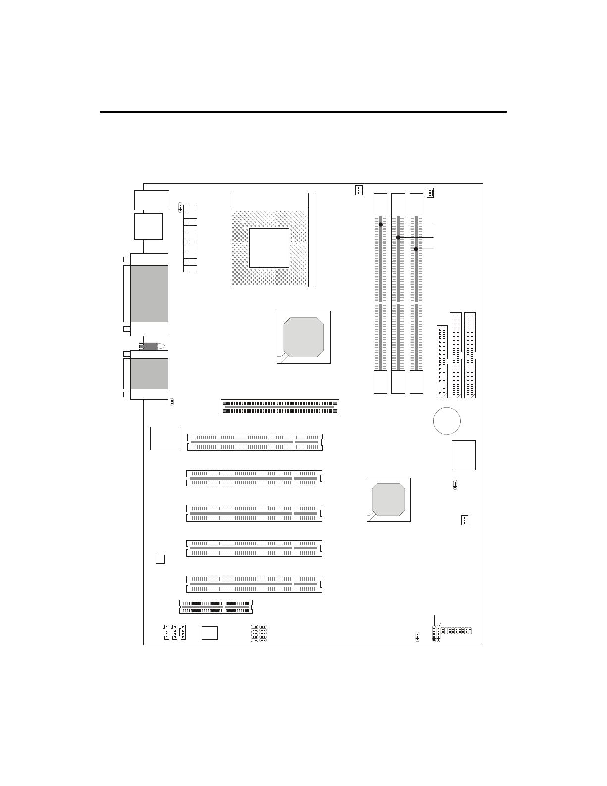
Mainboard Layout
MS-6380 ATX Mainboard
(K7T266 Pro)
JMDM
J
A
U
X
JCD
Top: Mouse
Bottom:
Keyboard
USB Ports
Top: Parallel
Port
Bottom:
COM A &
COM B
Top : Ga me
Port
Bottom:
Audio Ports
JKBV1
CFAN1
A
T
X
P
o
w
e
r
S
u
p
p
l
y
Socket 462
81)
86&!$$
Winbond
W83627 HF-AW
Codec
,,4
,,4
1
,
-
1
,
-
.
,
,
BATT
+
AGP Slot
PCI Slot 2
PCI Slot 3
CNR Slot
BIOS
SFAN1
81)
86& !!
JMDM1
,,4!
PSFAN1
J8
PCI Slot 1
PCI Slot 4
PCI Slot 5
JUSB2
JUSB3
JGL1
JFP1
JBAT1
J6
Diagnostic LED
PC2PC
Controller
MS-6380 provides three types of models to meet consumers
diverse needs: K7T266 Pro, K7T266 Pro-R and K7T266 Pro-RU.
Page 5
Introduction
1-5
JMDM
J
A
U
X
JCD
Top: Mouse
Bottom:
Keyboard
USB Ports
Top: Parallel
Port
Bottom:
COM A &
COM B
Top : Ga me
Port
Bottom:
Audio Ports
JKBV1
CFAN1
A
T
X
P
o
w
e
r
S
u
p
p
l
y
Socket 462
81)
86&!$$
Winbond
W83627 HF-AW
Codec
,,4
,,4
1
,
-
1
,
-
.
,
,
BATT
+
AGP Pro Slot
PCI Slot 2
PCI Slot 3
CNR Slot
BIOS
SFAN1
81)
86& !!
JMDM1
,,4!
PSFAN1
J8
PCI Slot 1
PCI Slot 4
PCI Slot 5
IDE4
IDE3
P
R
O
M
IS
E
2
0
2
6
5
R
JUSB2
JUSB3
JGL1
JFP1
JBAT1
JWR1
J6
Diagnostic LED
PC2PC
Controller
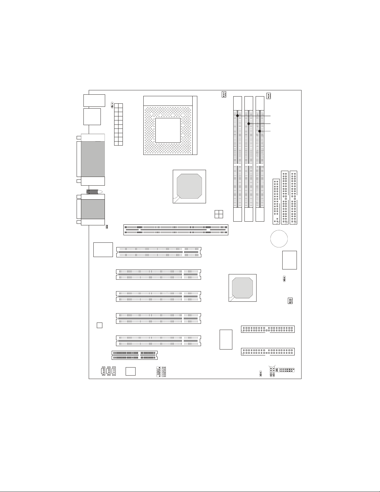
MS-6380 ATX Mainboard
(K7T266 Pro-R)
Page 6
Chapter 1
1-6
JMDM
J
A
U
X
JCD
Top: Mouse
Bottom:
Keyboard
USB Ports
Top: Parallel
Port
Bottom:
COM A &
COM B
Top : Ga me
Port
Bottom:
Audio Ports
JKBV1
CFAN1
A
T
X
P
o
w
e
r
S
u
p
p
l
y
Socket 462
81)
86&!$$
Winbond
W83627 HF-AW
Codec
,,4
,,4
1
,
-
1
,
-
.
,
,
BATT
+
AGP Pro Slot
PCI Slot 2
PCI Slot 3
CNR Slot
BIOS
SFAN1
81)
86& !!
JMDM1
,,4!
PSFAN1
J8
PCI Slot 1
PCI Slot 4
PCI Slot 5
NEC
USB 2.0
Host
Controller
IDE4
IDE3
P
R
O
M
IS
E
2
0
2
6
5
R
JUSB1
JUSB2
JUSB3
JGL1
JFP1
JBAT1
JWR1
J6
Diagnostic LED
PC2PC
Controller
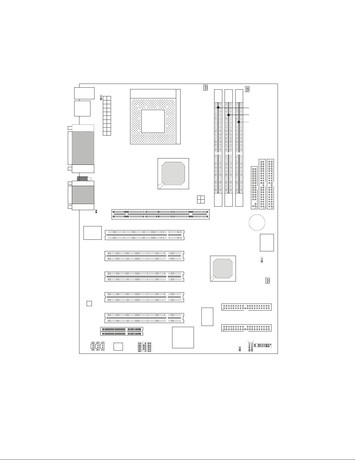
MS-6380 ATX Mainboard
(K7T266 Pro-RU)
Page 7

Introduction
1-7
Quick Components Guide
Component Function Reference
DDR1~3 Installing DDR SDRAM modules See p. 2-5~2-6
Socket 462 Installing CPU See p. 2-2~2-4
CFAN1 Connecting to CPUFAN See p. 2-20
SFAN1 Connecting to SYSTEM FAN See p. 2-20
PSFAN1 Connecting to Power Supply FAN See p. 2-20
ATX Power Supply Installing power supply See p. 2-7
IDE1& IDE2 Connecting to IDE hard disk drive See p.2-13
IDE3& IDE4 Connecting to IDE RAID HDD See p.2-14
FDD1 Connecting to floppy disk drive See p.2-12
JUSB1~3 Connecting to USB interfaces See p. 2-22~2-26
PCI Slot 1~5 Installing expansion cards See p. 2-30
AGP/AGP PRO Slot Installing AGP (Pro) cards See p. 2-30
CNR Slot Installing expansion cards See p. 2-30
JMDM1 Connecting to modem module See p. 2-18
JBAT1 Clearing CMOS data See p. 2-28
JFP1 Connecting to case See p. 2-15
JGL1 Connecting to power saving LED See p. 2-17
J6 Connecting to IR module See p. 2-19
J8 Connecting to chassis intrusion switch See p. 2-18
JWR1 Connecting to AGP Pro cards power cable See p. 2-27
JKBV1 Enabling Keyboard wake up function See p. 2-29
Page 8

Chapter 1
1-8
! ATX Form Factor
! CPU: Socket A for AMD
®
Duron/Athlon Processor
! Memory: 3 PC1600/PC2100 DDR DIMMs
! Slot: 1 AGP/AGP PRO slot, 1 CNR slot, 5 PCI slots
! I/O: 2 serial ports. 1 parallel port, 6 USB 1.1 ports, 1 floppy port, 1 IrDA
connector, 3 Audio/1 Game port (for K7T266 Pro & K7T266 Pro-R)
! I/O: 2 serial ports. 1 parallel port, 4 USB 1.1 & 4 USB 2.0 ports, 1 floppy
port, 1 IrDA connector, 3 Audio/1 Game port ( for K7T266 Pro-RU)
! USB Interface: USB 1.1 PC to PC Networking & USB 2.0 HC On-Board
(Optional)
! 2 IDE RAID connectors (Optional)
! Fuzzy Logic III overclocking utility
! D-LED -- 4 LEDs embedded in the mainboard
! PC Alert III system hardware monitor
! Audio: 2 Channel S/W audio integrated
! PCI 2.2 LAN Wake up Function
! Modem (External/Internal) Ring Wake up Function
Key Features
Page 9
Introduction
1-9
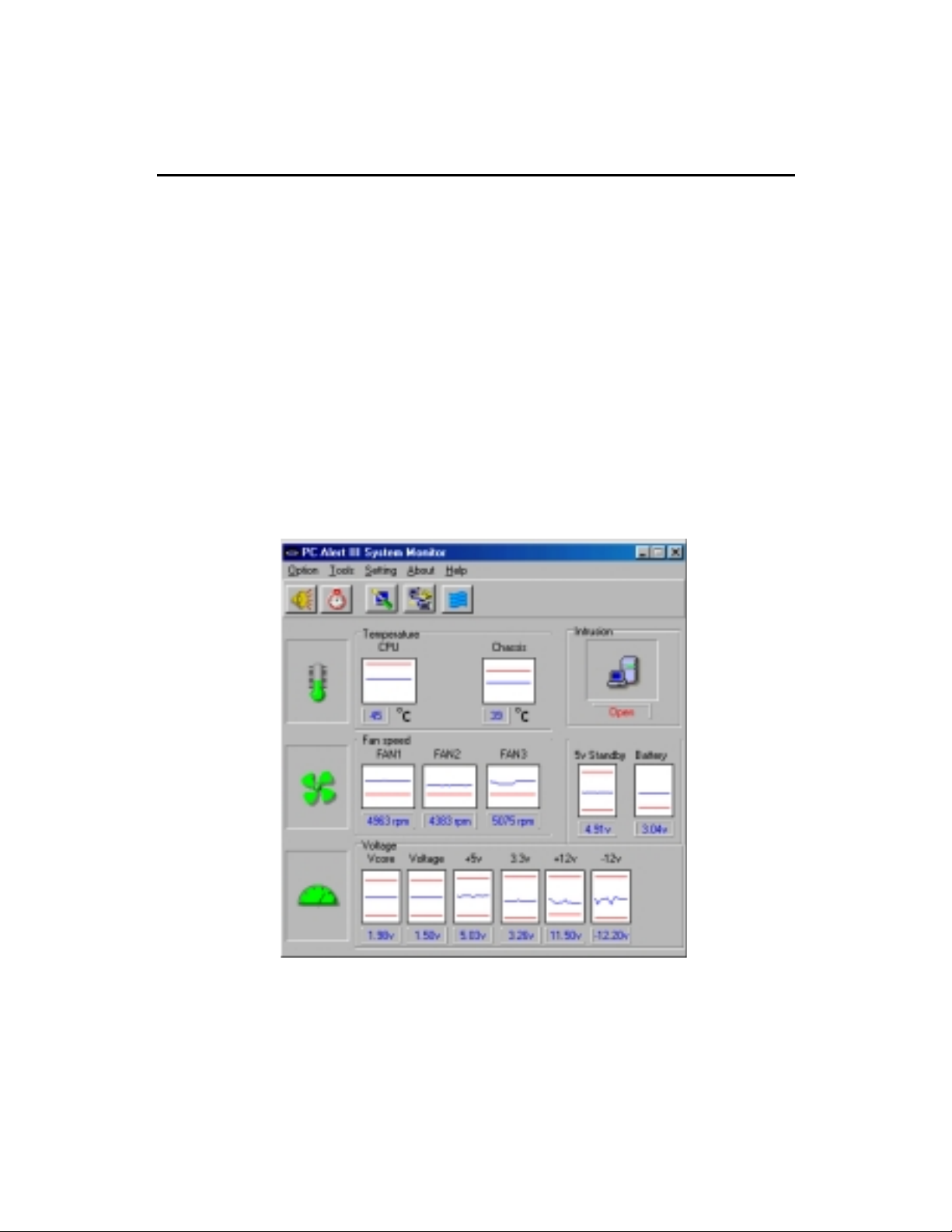
PC Alert III
The PC AlertTM III is an utility you can find in the CD-ROM disk. The
utility is just like your PC doctor that can detect the following PC hardware
status during real time operation:
* monitor CPU & system temperatures
* monitor fan speed(s)
* monitor system voltage
* monitor chassis intrusion
If one of the items above is abnormal, the program main screen will be immediately shown on the screen, with the abnormal item highlighted in red. This will
continue to be shown,until user disables the warning.
MSI Special Features
Note: Items shown on PC Alert III vary depending on your systems status.
Page 10

Chapter 1
1-10
Features:
! Network Management
- Monitoring & remote control
! Basic System Utilities
- Scandisk & Defragment to maintain your HDD
! 3D Graphics Design
- Enables a more friendly user interface
! Sofware Utilities
- SoftCooler Optimized Cooling
Page 11
Introduction
1-11
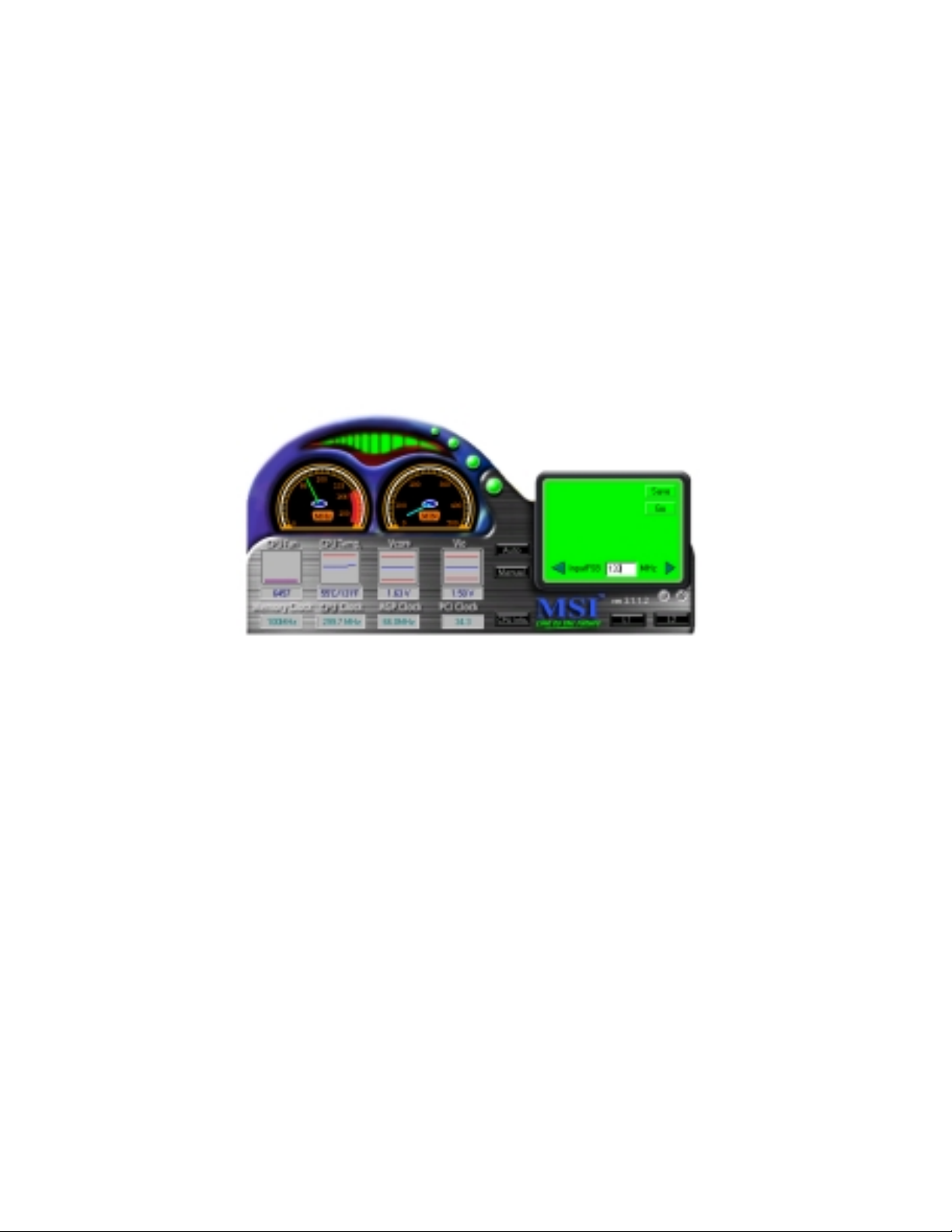
Fuzzy Logic III
The Fuzzy Logic III utility allows users to overclock the CPU FSB
(Front Side Bus) frequency in the Windows environment. Select the CPU
frequency you prefer and click Go to apply the frequency or click Save
allowing the system to run at the specified frequency each time when the
system is powered on.
Features:
! Display Current System Status
- CPU Fan
- CPU Temp.
- Vcore
- Vio
- Memory Clock
- CPU Clock
- AGP Clock
- PCI Clock
! Adjust CPU FSB Frequency
Page 12
Chapter 1
1-12
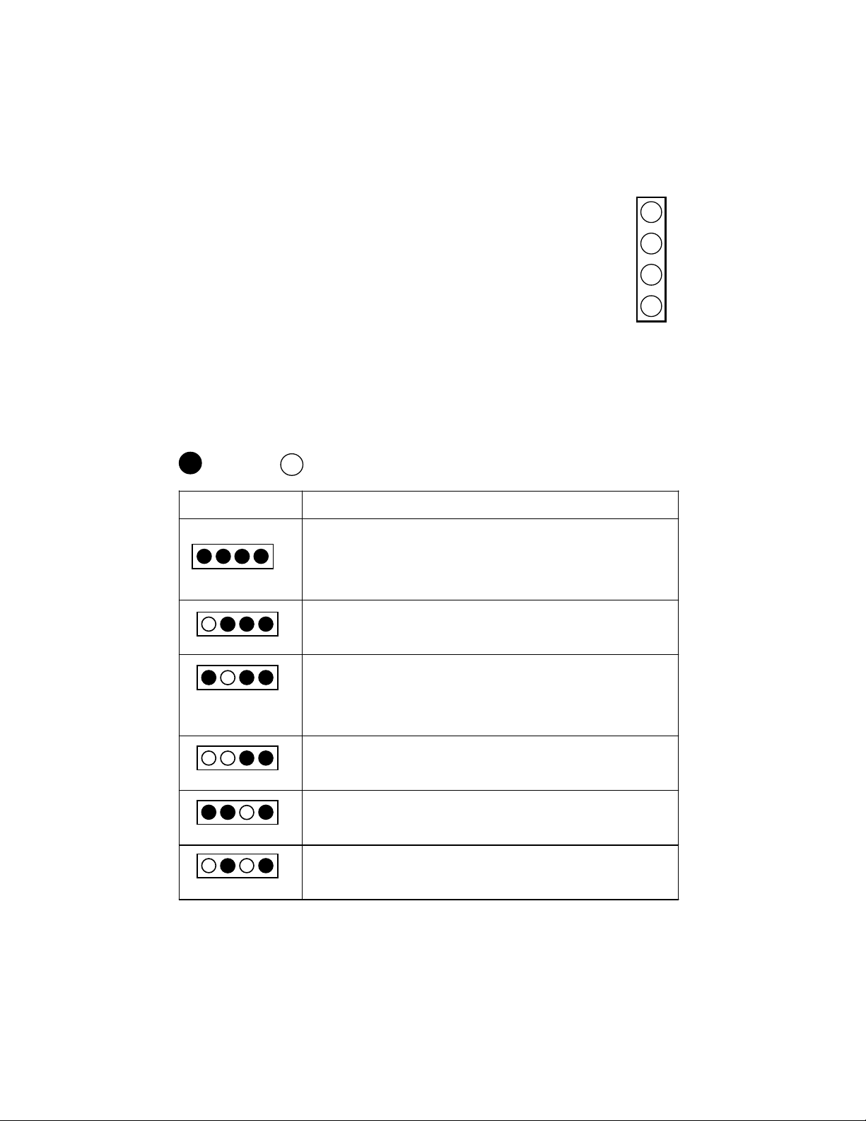
D-LED
D-LED Description
System Power ON
- The D-LED will hang here if the processor is damaged or not
installed properly.
Early Chipset Initialization
Memory Detection Test
- Testing onboard memory size. The D-LED will hang if the
memory module is damaged or not installed properly.
Decompressing BIOS image to RAM for fast booting.
Initializing Keyboard Controller.
Testing VGA BIOS
- This will start writing VGA sign-on message to the screen.
Red
Green
The D-LED uses graphic signal display to help
users understand their system. Four LEDs embedded in
the mainboard provide up to 16 combinations of signals to
debug the system. The 4 LEDs can debug all problems that
fail the system, such as VGA, RAM or other failures. This
special feature is very useful for the overclocking users.
These users can use the feature to detect if there are any
problems or failures.
1
2
3
4
Diagnostic LED
1 2 3 4
Page 13
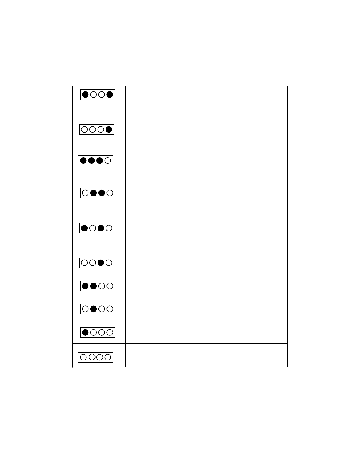
Introduction
1-13
Processor Initialization
- This will show information regarding the processor (like brand
name, system bus, etc)
Testing RTC (Real Time Clock)
Initializing Video Interface
- This will start detecting CPU clock, checking type of video
onboard. Then, detect and initialize the video adapter.
BIOS Sign On
- This will start showing information about logo, processor
brand name, etc.
Testing Base and Extended Memory
- Testing base memory from 240K to 640K and extended
memory above 1MB using various patterns.
Assign Resources to all ISA.
Initializing Hard Drive Controller
- This will initialize IDE drive and controller.
Initializing Floppy Drive Controller
- This will initializing Floppy Drive and controller.
Boot Attempt
- This will set low stack and boot via INT 19h.
Operating System Booting
Page 14

Hardware Setup
2-1
Chapter 2.
Hardware Setup
This chapter provides you with the information about hardware setup
procedures. While doing the installation, be careful in holding the components and follow the installation procedures. For some components, if you
install in the wrong orientation, the components will not work properly.
Use a grounded wrist strap before handling computer components.
Static electricity may damage the components.
Central Processing Unit (CPU) 2-2
Memory 2-5
Power Supply 2-7
Back Panel 2-8
Connectors 2-12
Jumpers 2-28
Slots 2-30
This chapter contains the following topics:
Page 15
Chapter 2
2-2
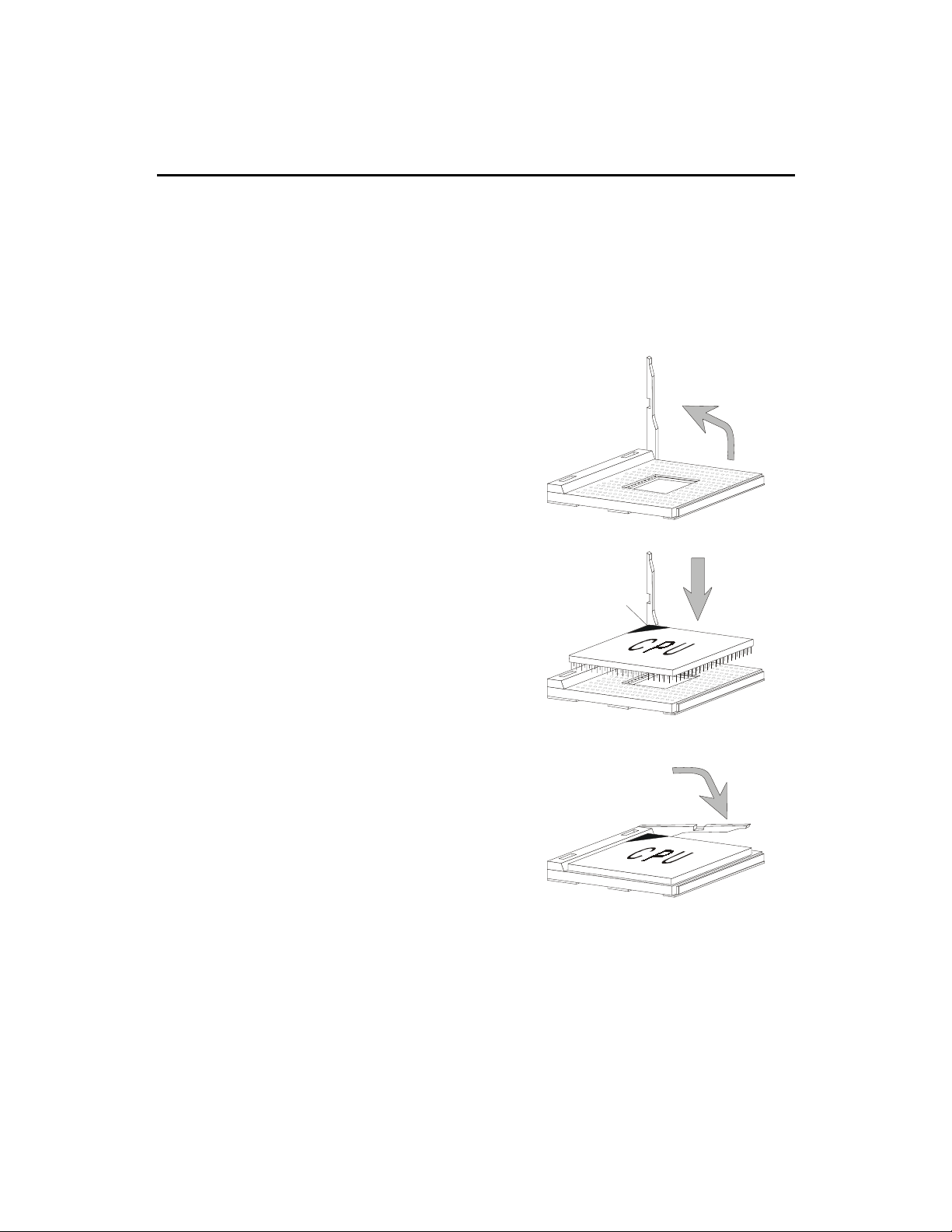
1. Pull the lever sideways away
from the socket. Then, raise
the lever up to a 90-degree
angle.
3. Hold the CPU firmly, and
then press the lever down to
complete the installation.
Central Processing Unit: CPU
CPU Installation Procedures
2. Look for the cut edge. The
cut edge should point
towards the lever pivot. The
CPU will only fit in the
correct orientation.
The mainboard supports AMD® AthlonTM and DuronTM processor.
The mainboard uses a CPU socket called Socket A for easy CPU installation.
Make sure the CPU has a Heat Sink and a cooling fan attached on the top to
prevent overheating. If you do not find the Heat Sink and cooling fan,
contact your dealer to purchase and install them before turning on the
computer.
Open Lever
Cut edge
Sliding
Plate
Close
Lever
Page 16

Hardware Setup
2-3
Thermal Issue for CPU
As processor technology pushes to faster speeds and higher
performance, thermal management becomes increasingly cru-
cial when building computer systems. Maintaining the proper
thermal environment is key to reliable operation. As such, the processor must
be maintained in the specified thermal requirements. AMD recommends the
use of high performance thermal interface material.
AMD Athlon/Duron processor with a speed of 600MHz and above requires LARGER heatsink and fan. You also need to add thermal grease between the CPU and heatsink to improve heat dissipation. Then, make sure that
the CPU and heatsink are securely fastened and in good contact with each
other. These are needed to prevent damaging the processor and ensuring
reliable operation.
You can check AMDs web site for more information on proper cooling: http:/
/www.amd.com/products/cpg/athlon/pdf/cooling_guide.pdf
!
WARNING!
Page 17

Chapter 2
CPU Core Speed Derivation Procedure
If CPU Clock = 100MHz
Core/Bus ratio = 7
then CPU core speed = Host Clock x Core/Bus ratio
= 100MHz x 7
= 700MHz
CPU Clock Frequency Selection through BIOS
To set the clock frequency of the CPU installed on the motherboard,
refer to Hardware Monitor Setup of BIOS on page 3-26.
The default hardware configuration for CPU Clock Frequency is 100MHz.
Therefore, to use a 133MHz CPU, you need to adjust the CPU clock up to
133MHz by changing the CPU clock in the BIOS Setup utility.
!
WARNING!
While replacing the CPU, always turn off the ATX
power supply or unplug the power cable of the ATX
power supply from grounded outlet first to ensure the
safety of CPU.
2-4
Page 18
Hardware Setup
2-5
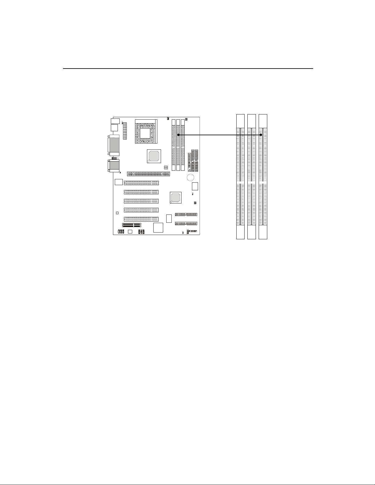
The mainboard provides 3 sockets for 184-pin, 2.5V DDR DIMM with 6
memory banks. To operate properly, at least one DIMM module must be
installed.
Memory
DDR DIMM Slots
(DDR 1~3)
You can install PC1600/PC2100 DDR SDRAM modules on the DDR
DIMM slots (DIMM 1~3).
DDR (Double Data Rate) SDRAM is similar to conventional SDRAM,
but doubles the rate by transfering data twice per cycle. It transfers data on
both the rising and falling edges of the clock. Conventional SDRAM only
uses the rising edge of the clock to transfer data. Therefore, conventional
SDRAM is called SDR (Single Data Rate) SDRAM.
DDR SDRAM uses 2.5 volts as opposed to 3.3 volts used in SDR
SDRAM, and requires 184-pin DIMM modules rather than 168-pin DIMM
modules used by SDR SDRAM. DDR SDRAM is also known as SDRAM-II,
DDR DRAM and DSDRAM (Double-Speed DRAM).
Two types of DDR are available at the time of writing: PC1600 & PC2100.
PC1600 DDR SDRAM running at 100MHz will produce about 1.6GB/s memory
bandwidth. PC2100 running at 133MHz will produce 2.1GB/s memory
bandwidth. High memory bandwidth makes DDR an ideal solution for high
performance PC, workstations and servers.
Page 19
Chapter 2
2-6
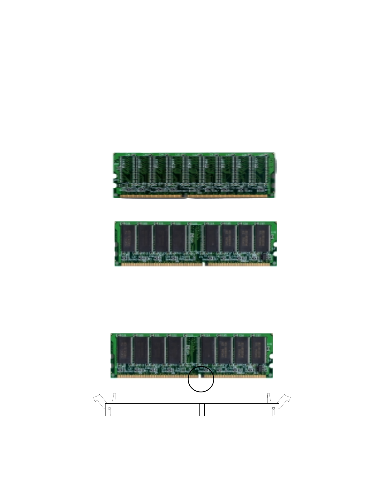
DDR Module Installation
You can install either single sided or double sided 184-pin DDR DIMM
modules into DDR DIMM slots to meet your needs. Different from the SDR
DIMM, the DDR DIMM has only one notch on the center of module. The
number of pins on either side of the breaks are different. The module will only
fit in the right orientation.
1. Insert the DIMM module vertically into the DDR DIMM slot. Make sure the
notch is on the right orientation.
2. The plastic clips at sides of the DIMM slot will automatically close.
Volt
Single Sided DIMM
Double Sided DIMM
Page 20
Hardware Setup
2-7
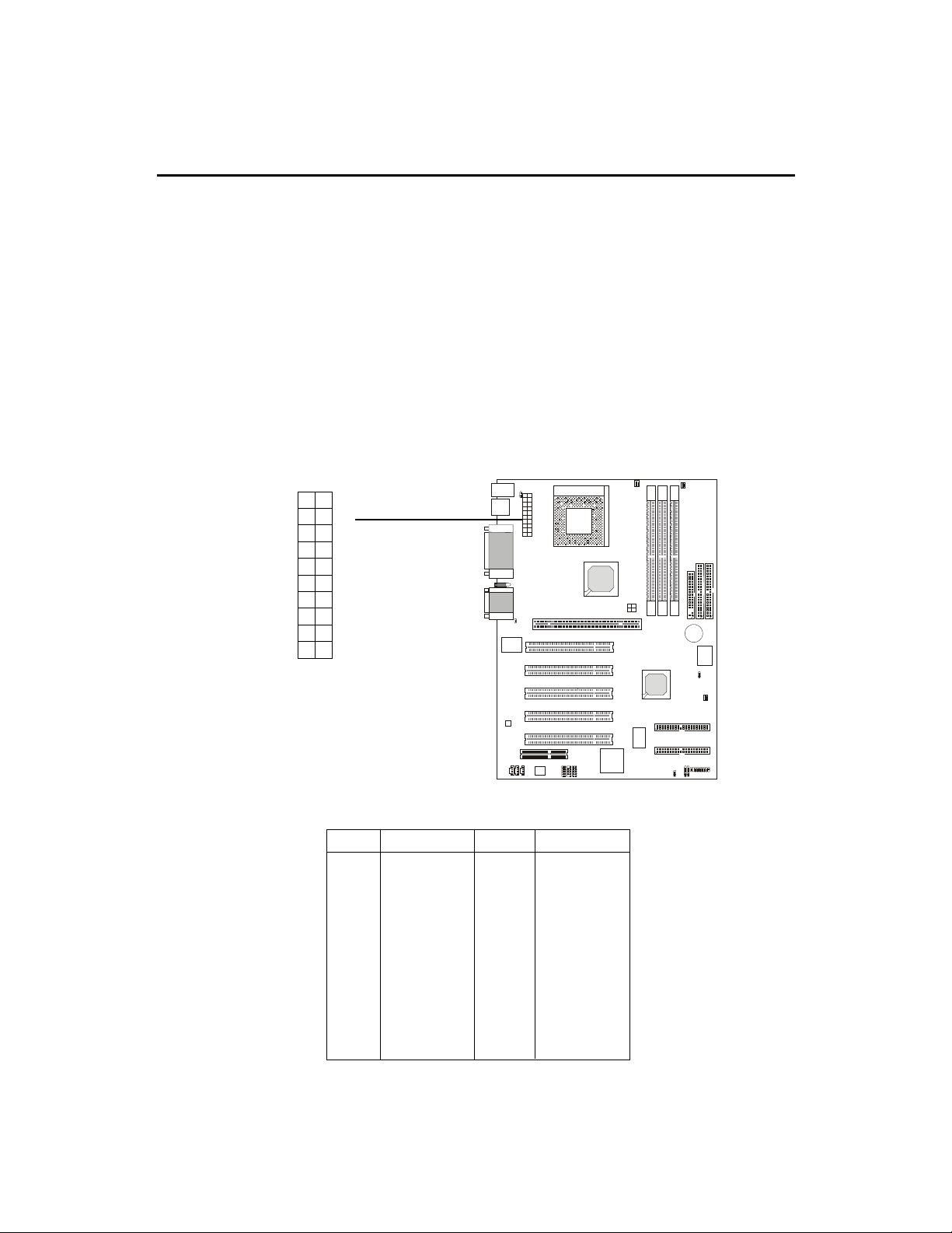
Power Supply
ATX 20-Pin Power Supply
This connector allows you to connect to an ATX power supply. To
connect to the ATX power supply, make sure the plugs of the power supply is
inserted in the proper orientation and the pins are aligned. Then push down
the power supply firmly into the connector.
ATX
Power Connector
The mainboard supports ATX power supply for the power system.
Before inserting the power supply connector, always make sure that all components are installed properly to ensure that no damage will be caused.
10
1
20
11
PIN SIGNAL
11 3.3V
12 -12V
13 GND
14 PS_ON
15 GND
16 GND
17 GND
18 -5V
19 5V
20 5V
PIN SIGNAL
1 3.3V
2 3.3V
3 GND
45V
5 GND
65V
7 GND
8 PW_OK
9 5V_SB
10 12V
Page 21
Chapter 2
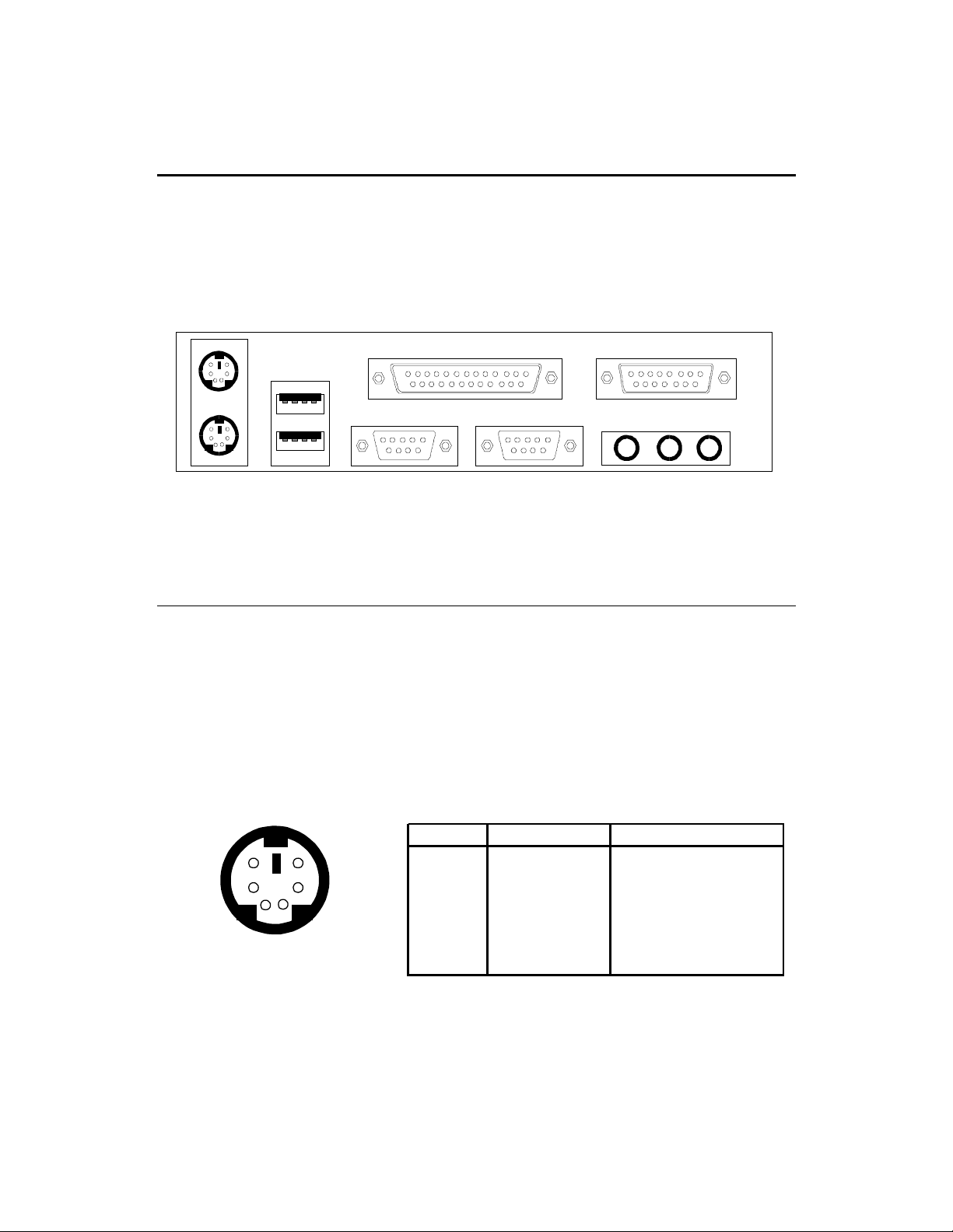
Back Panel
The Back Panel provides the following connectors:
Mouse
Keyboard USB
Parallel
COM A COM B L-out L-in
Midi/Joystick
MIC
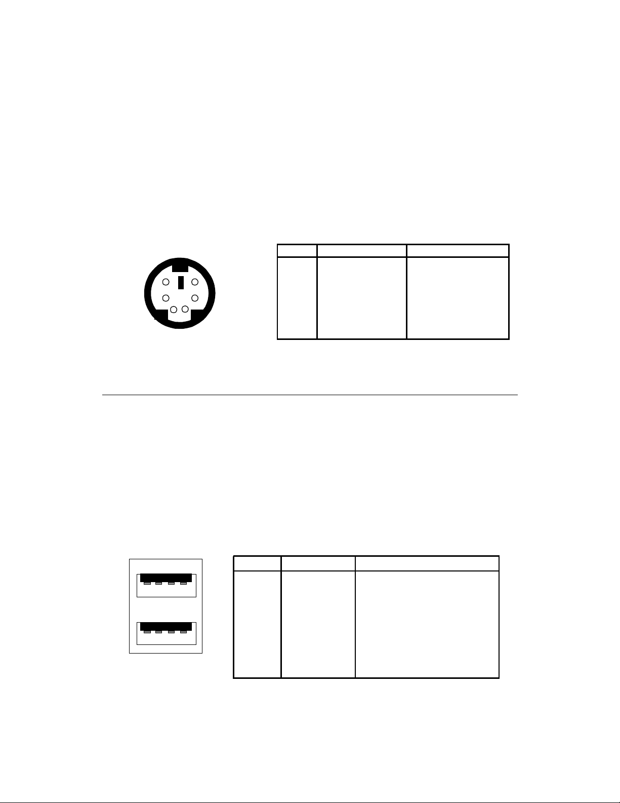
Mouse Connector
The mainboard provides a standard PS/2® mouse mini DIN connector
for attaching a PS/2® mouse. You can plug a PS/2® mouse directly into this
connector.
6
4
2
PS/2 Mouse (6-pin Female)
5
3
1
Pin Definition
PIN SIGNAL DESCRIPTION
1 Mouse DATA Mouse DATA
2 NC No connection
3 GND Ground
4 VCC +5V
5 Mouse Clock Mouse clock
6 NC No connection
2-8
Page 22
Hardware Setup
Keyboard Connector
The mainboard provides a standard PS/2® keyboard mini DIN connector for attaching a PS/2® keyboard. You can plug a PS/2® keyboard directly into
this connector.
Pin Definition
PIN SIGNAL DESCRIPTION
6
21
PS/2 Keyboard (6-pin Female)
5
34
1 Keyboard DATA Keyboard DATA
2 NC No connection
3 GND Ground
4 VCC +5V
5 Keyboard Clock Keyboard clock
6 NC No connection
USB Connectors
The mainboard provides a UHCI (Universal Host Controller Interface)
Universal Serial Bus root for attaching USB devices such as keyboard, mouse
or other USB-compatible devices. You can plug the USB device directly into
ths connector.
USB Port Description
1 2 3 4
5 6 7 8
USB Ports
PIN SIGNAL DESCRIPTION
1 VCC +5V
2 -Data 0 Negative Data Channel 0
3 +Data0 Positive Data Channel 0
4 GND Ground
5 VCC +5V
6 +Data 1 Positive Data Channel 1
7 -Data 1 Negative Data Channel 1
8 GND Ground
2-9
Page 23
Chapter 2
2-10
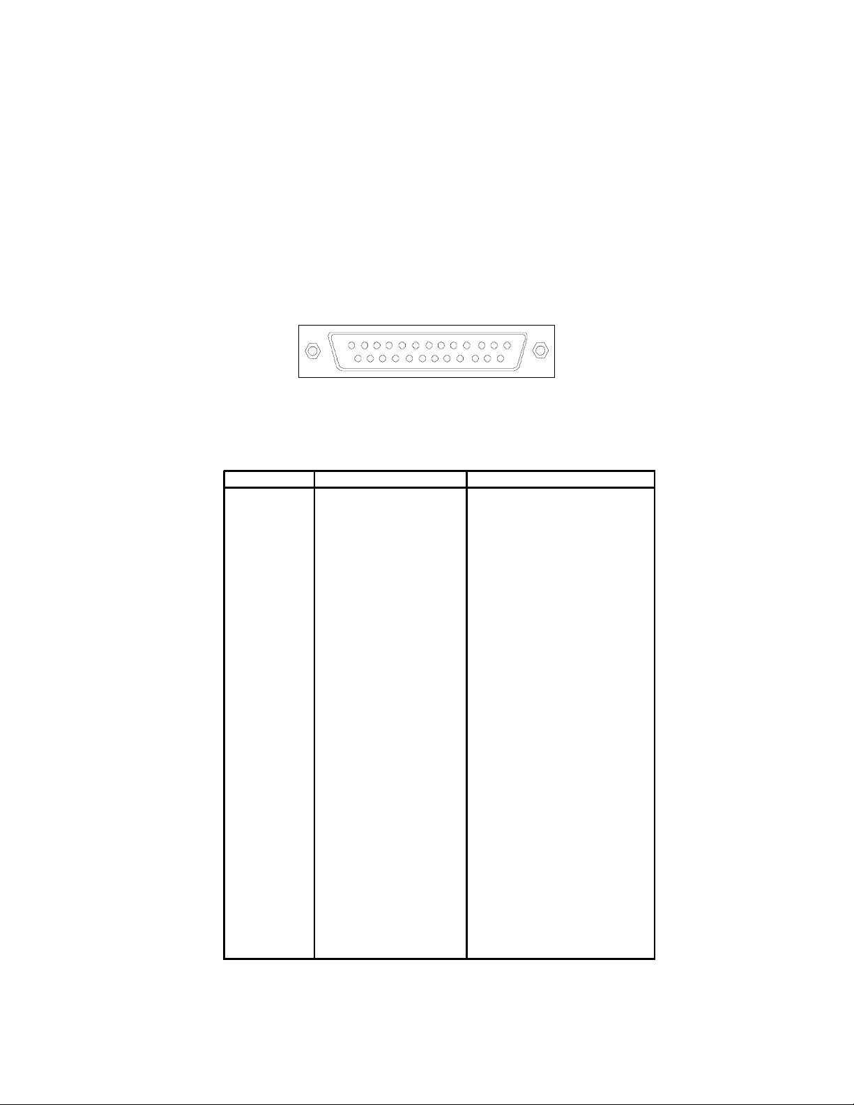
Parallel Port Connector
The mainboard provides a 25-pin female centronic connector for LPT.
A parallel port is a standard printer port that supports Enhanced Parallel Port
(EPP) and Extended Capabilities Parallel Port (ECP) mode.
13
1
1425
PIN SIGNAL DESCRIPTION
1 STROBE Strobe
2 DATA0 Data0
3 DATA1 Data1
4 DATA2 Data2
5 DATA3 Data3
6 DATA4 Data4
7 DATA5 Data5
8 DATA6 Data6
9 DATA7 Data7
10 ACK# Acknowledge
11 BUSY Busy
12 PE Paper End
13 SELECT Select
14 AUTO FEED# Automatic Feed
15 ERR# Error
16 INIT# Initialize Printer
17 SLIN# Select In
18 GND Ground
19 GND Ground
20 GND Ground
21 GND Ground
22 GND Ground
23 GND Ground
24 GND Ground
25 GND Ground1
Pin Definition
Page 24
Hardware Setup
2-11
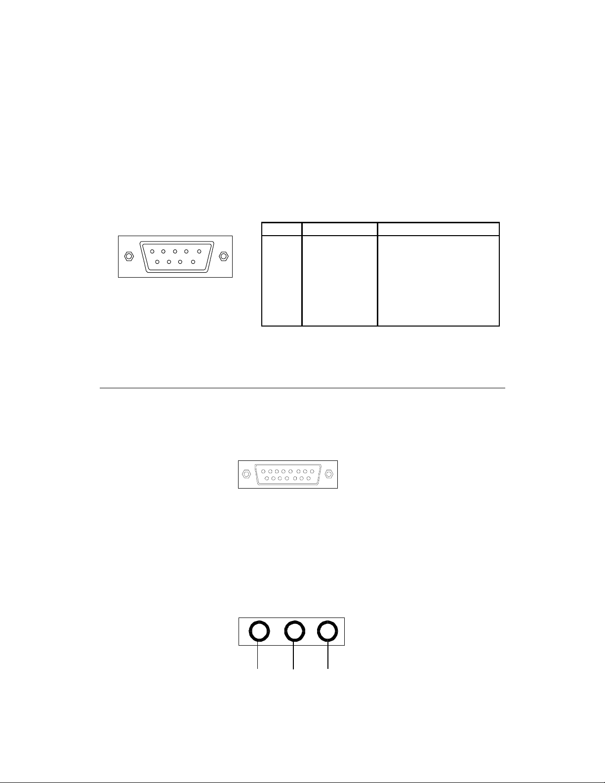
Serial Port Connector: COM A & COM B
The mainboard has two 9-pin male DIN connectors for serial port COM
A and COM B. You can attach a serial mouse or other serial devices.
1 2 3 4 5
6 7 8 9
PIN SIGNAL DESCRIPTION
1 DCD Data Carry Detect
2 SIN Serial In or Receive Data
3 SOUT Serial Out or Transmit Data
4 DTR Data Terminal Ready)
5 GND Ground
6 DSR Data Set Ready
7 RTS Request To Send
8 CTS Clear To Send
9 RI Ring Indicate
9-Pin Male DIN Connectors
Pin Definition
Joystick/Midi Connectors
You can connect a joystick or game pad to this connector.
Audio Port Connectors
Line Out is to connect speakers or headphones. Line In is a connector
for external CD player, Tape player or other audio devices. Mic is used to
connect to a microphone.
Line Out
Line In MIC
Page 25
Chapter 2
2-12
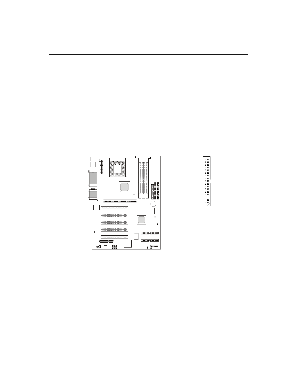
FDD1
12
33
34
The mainboard provides connectors to connect to FDD, IDE HDD,
case, modem, LAN, USB Ports, IR module and CPU/Power supply/System
FAN.
Floppy Disk Drive Connector: FDD1
The mainboard provides a standard floppy disk drive connector that
supports 360K, 720K, 1.2M, 1.44M and 2.88M floppy disk types.
Connectors
Page 26
Hardware Setup
2-13
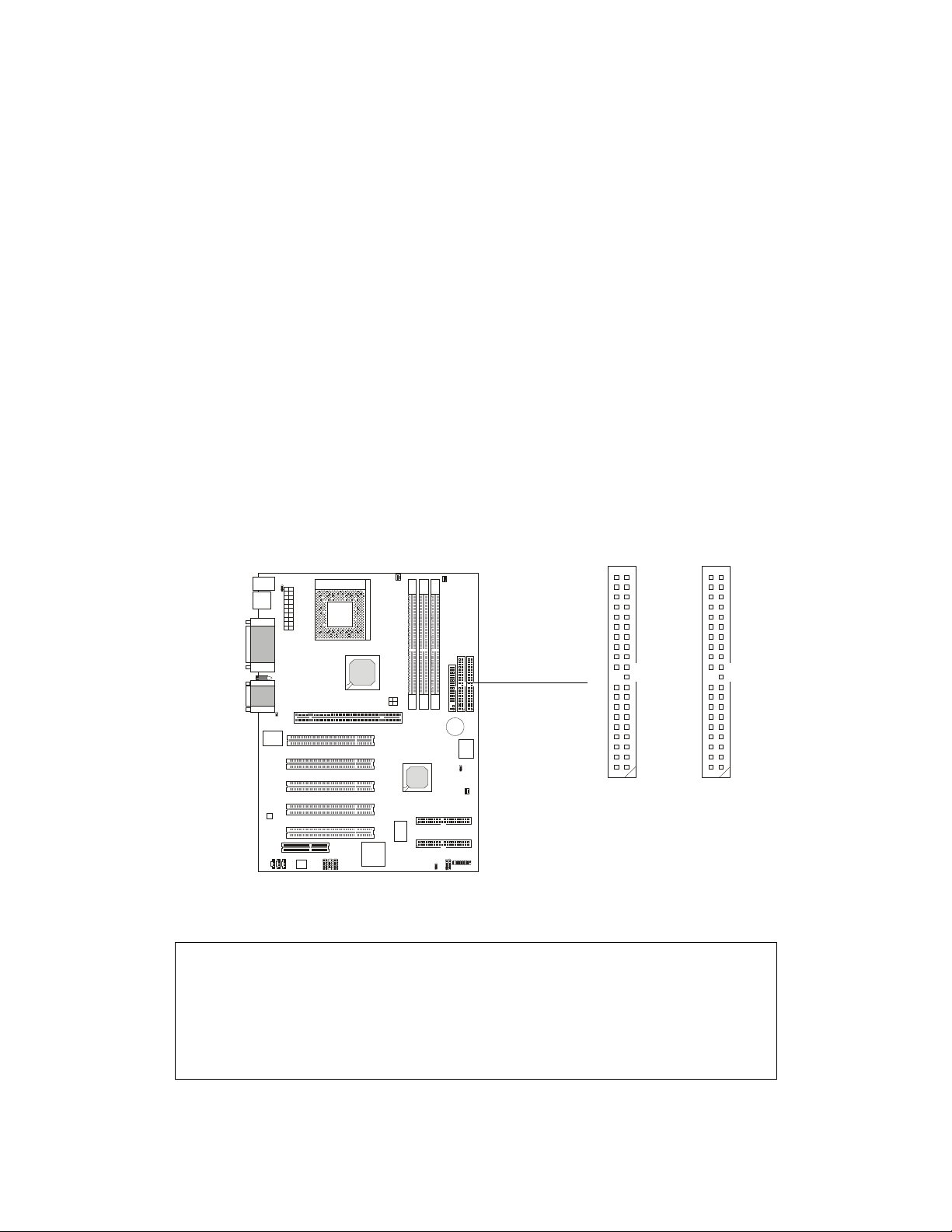
Hard Disk Connectors: IDE1 & IDE2
The mainboard uses an IDE controller on the VIA® VT8233 chipset that
provides PIO mode 0-4, Bus Master, and Ultra DMA 33/66/100 modes. It has
two HDD connectors IDE1 (Primary) and IDE2 (Secondary). You can connect
up to four hard disk drives, CD-ROM or 120MB Floppy to IDE1 and IDE2.
IDE1 (Primary IDE Connector)
- The first hard disk drive should always be connected to IDE1. You can
connect a Master and a Slave drive to IDE1.
IDE2 (Secondary IDE Connector)
- You can connect a Master and a Slave drive to IDE2.
Primary IDE Connector
11
Secondary IDE Connector
!TIP:
If you install two hard disks on cable, you must configure the second
drive to Slave mode by setting its jumper. Refer to the hard disk documentation supplied by hard disk vendors for jumper setting instructions.
2
40 39
2
40 39
Page 27
Chapter 2
2-14
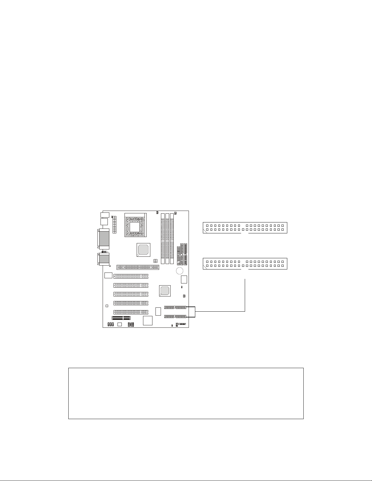
IDE RAID Connectors: IDE3 & IDE4 (Optional)
The mainboard offers a low-cost RAID (Redundant Array of Independent Disks) solution by integrating two IDE RAID connectors that support
PIO mode 0-4, Bus Master, and Ultra DMA 33/66/100 modes. The IDE RAID
connectors allow you to connect Ultra ATA/DMA hard disks and use RAID
technology for high performance, data security and fault tolerance. The connectors support RAID 0 (striping) and RAID 1 (mirroring).
IDE RAID Connectors
- You can connect a Master and a Slave drive to each IDE RAID connector.
- For more information on IDE RAID, please refer to IDE RAID Manual.
1
2
39
40
1
2
39
40
IDE3
IDE4
!TIP:
If you install two hard disks on cable, you must configure the second
drive to Slave mode by setting its jumper. Refer to the hard disk documentation supplied by hard disk vendors for jumper setting instructions.
Page 28
Hardware Setup
2-15
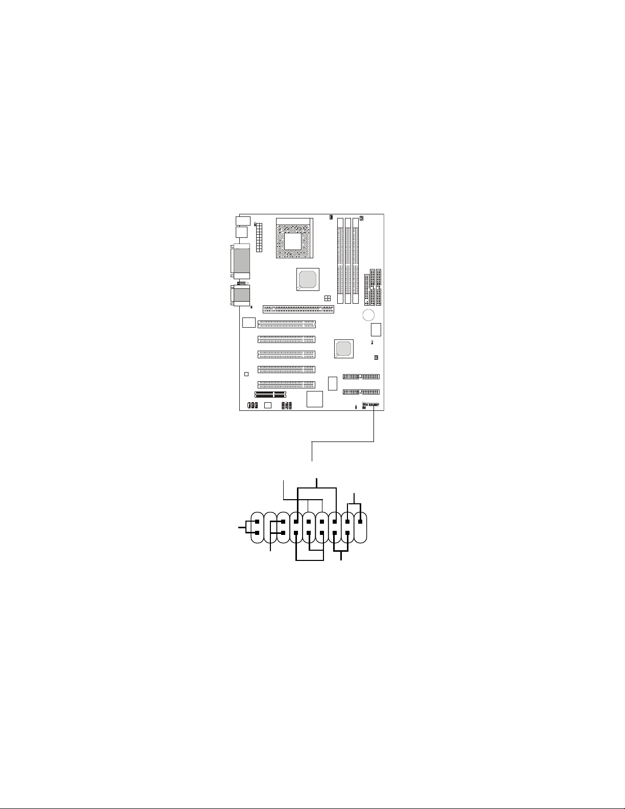
Case Connector: JFP1
The case connector block JFP1 allows you to connect to the Power
Switch, Reset Swtich, Keylock, Speaker, Power LED, and HDD LED on the
case.
JFP1
Power
Switch
Power
LED
+
Reset
Switch
HDD
LED
+
Speaker
Buzzer
(short pin)
14
15
Keylock
Page 29

Chapter 2
2-16
Power Switch
Connect to a 2-pin push button switch.
Reset Switch
Reset switch is used to reboot the system rather than turning the power ON/
OFF. Avoid rebooting while the HDD is working. You can connect the
Reset switch from the system case to this pin.
Power LED
The Power LED is lit while the system power is on.
Speaker
Speaker from the system case is connected to this pin.
If on-board Buzzer is available, then:
Always short pin 14-15 to enable on-board Buzzer
HDD LED
HDD LED shows the activity of a hard disk drive connected to the IDE1 or
IDE2 connector. Avoid turning the power off while the HDD is working.
You can connect the HDD LED from the system case to this pin.
Keylock
Keylock allows you to disable the keyboard for security purpose. You can
connect the keylock to this pin.
Page 30
Hardware Setup
2-17
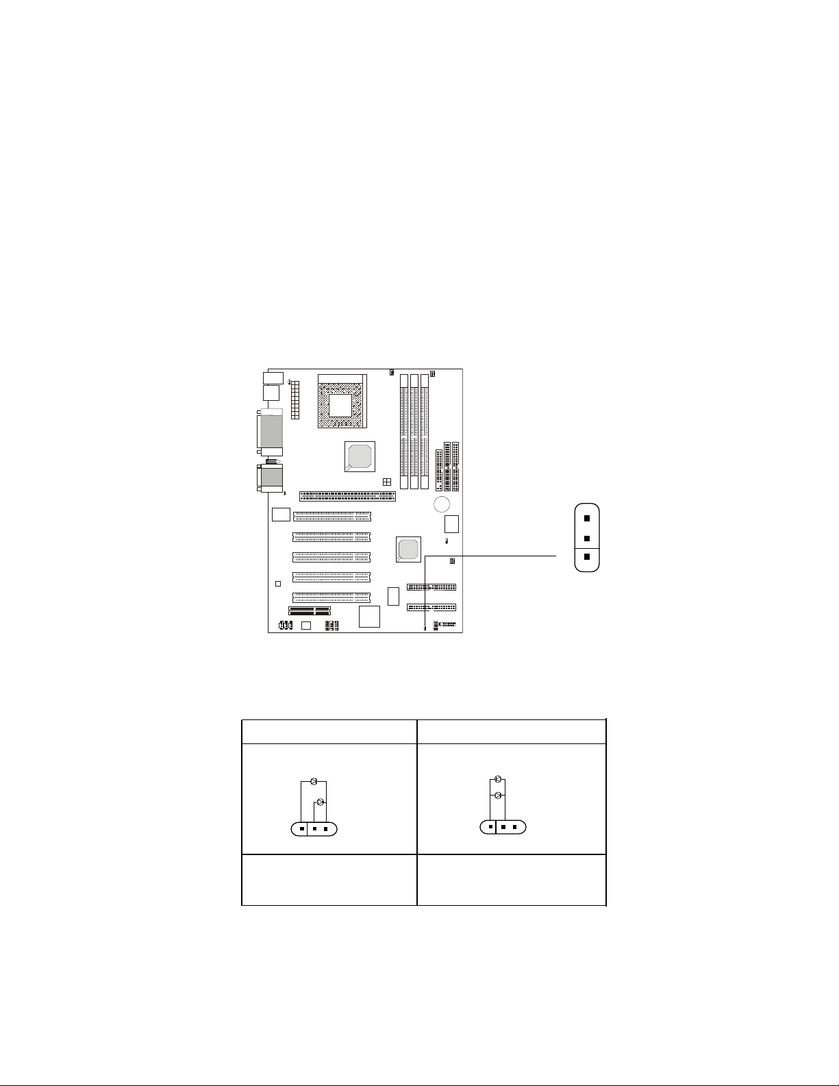
Power Saving LED Connector: JGL1
JGL1 is connected to a power saving LED. There are two types of LED
that you can use: 3-pin or 2-pin (ACPI request) LED. If connected to a 2-pin
LED, the LED light is green when system in turned on, and turns to orange
color while entering the sleep state. For 3-pin LED, the LED is lit when system
is on, and blinks during the sleep state.
1-2 Single Color 1-2 Dual Color
1-3 Blink
3-Pin LED 2-Pin LED
!
Green Color
Orange Color
!
Green Color
Orange Color
JGL1
1
Page 31

Chapter 2
2-18
Chassis Intrusion Switch Connector: J8
This connector is connected to a 2-pin chassis switch. If the chassis is
opened, the switch will be short. The system will record this status and show
a warning message on the screen. To clear the warning, you must enter the
BIOS utility and clear the record.
J8
JMDM1
Wake On Ring Connector: JMDM1
This connector allows you to connect to a modem card with Wake On
Ring function. The connector will power up the system when a signal is
received through the modem card.
NC
MDM_WAKEUP
NC
5VSB
1
GND
Page 32

Hardware Setup
2-19
IrDA Infrared Module Connector: J6
This connector allows you to connect to an IrDA Infrared module. You
must configure the setting through the BIOS setup to use the IR function.
J6
1
1VCC
2NC
3 IRRX
4 GND
5IRTX
Pin Signal
Modem-In Connector: JMDM
The connector is for modem with internal audio connector.
JMDM
GND
Mono_Out
Phone_In
Page 33

Chapter 2
2-20
CD-In Connector: JCD
The connector is for CD-ROM audio connector.
Aux Line-In Connector: JAUX
The connector is for DVD add-on card with Line-in connector.
JCD
JAUX
GND
L
R
GND
L
R
Page 34

Hardware Setup
2-21
Fan Power Connectors: CFAN1/SFAN1/PSFAN1
The CFAN1 (processor fan), SFAN1 (system fan) and PSFAN1
(power supply fan) support system cooling fan with +12V. It supports threepin head connector. When connecting the wire to the connectors, always
take note that the red wire is the positive and should be connected to the
+12V, the black wire is Ground and should be connected to GND. If the
mainboard has a System Hardware Monitor chipset on-board, you must use
a specially designed fan with speed sensor to take advantage of the CPU fan
control.
"Note:
1. Always consult the vendor for proper CPU cooling fan.
2. CPU Fan supports the fan control. You can install the PC Alert utility
that will automatically control the CPU Fan speed according to the
actual CPU temeperature.
SENSOR
+12V
GND
CFAN1
SENSOR
+12V
GND
SFAN1
SENSOR
+12V
GND
PSFAN1
Page 35

Chapter 2
2-22
USB Rear Panel Connectors: JUSB1, JUSB2 & JUSB3
MS-6380 mainboard provides two or three USB (Universal Serial Bus)
pin headers that allow you to connect optional USB ports for Rear Panel.
TWO USB Connectors: JUSB2/3 (for K7T266 Pro & K7T266 Pro-R)
If your mainboard comes with two USB pin headers, one of them will be
compatible with USB 1.1 specification and the other will implement USB PC to
PC Networking function.
The mainboard can offer five USB 1.1 ports and one USB PC2PC port.
1
9
2
10
Pin Description Pin Description
1 VCC 2 GND
3 USB0- 4 GND
5 USB0+ 6 USB1+
7 GND 8 USB1-
9 GND 10 VCC
JUSB3 Pin Definition
JUSB3
(USB 1.1)
Pin Description Pin Description
1 VCC 2 NC
3 USB0- 4 GND
5 USB0+ 6 USB1+
7 GND 8 USB1-
9GND 10NC
JUSB2 Pin Definition
JUSB2
1
9
2
10
(USB 1.1)
(USB PC to PC
Networking)
Page 36

Hardware Setup
2-23
THREE USB Connectors: JUSB1/2/3 (for K7T266 Pro-RU)
If your mainboard comes with three USB pin headers along with the
NEC USB 2.0 controller, two of them will comply with high-speed USB 2.0
specification and one will implement USB PC to PC Networking function.
USB 2.0 technology increases data transfer rate and is ideal for connecting to high-speed USB interface peripherals such as USB HDD, digital
cameras, MP3 players, printers, modems and the like. It is not recommended
to connect low-speed USB legacy keyboard and mouse to the USB 2.0 ports.
Please connect these USB legacy devices to the USB rear ports.
The mainboard can offer seven USB 1.1 ports and one USB PC2PC
port.
1
9
2
10
JUSB3
(USB 2.0)
Pin Description Pin Description
1 VCC 2 GND
3 USB0- 4 GND
5 USB0+ 6 USB1+
7 GND 8 USB1-
9 GND 10 VCC
JUSB1/3 Pin Definition
Pin Description Pin Description
1 VCC 2 NC
3 USB0- 4 GND
5 USB0+ 6 USB1+
7 GND 8 USB1-
9GND 10NC
JUSB2 Pin Definition
(USB 1.1 -- controlled by
VIA Southbridge)
1
9
2
10
JUSB1
(USB 2.0)
JUSB2
1
9
2
10
(USB PC to PC
Networking)
Page 37

Chapter 2
2-24
USB 2.0 Bracket
Connected to JUSB1 & JUSB3
Separately
To Attach the Optional USB 2.0 Ports:
1. Take out the USB 2.0 bracket
2. Locate the JUSB1 and JUSB3 pin headers on the motherboard.
3. Connect the USB cables from USB 2.0 bracket to the JUSB1 and JUSB 3
connectors separately.
4. Place the USB 2.0 Bracket into the appropriate slot of the system case.
Page 38

Hardware Setup
2-25
Note: USB PC to PC Networking feature allows users to transfer and receive
data from other computers or share system resources with other computers
without using any network adapter. See below for instructions.
To Attach the USB PC to PC cable
1. Check whether the package includes the following items. If any is
missing, contact your dealer.
2. Connect the USB Bracket cable to the JUSB2 pin header on the
mainboard. Locate the pin hole marked with the ARROW on the connector of USB Bracket and Pin# 2 of JUSB2. Then align the pin hole
with Pin# 2 to attach the USB Bracket.
3. Identify the B Type Connector on the bracket used for PC to PC Net-
working function.
JUSB2
Pin Hole marked
with ARROW
1
9
2
10
USB PC to PC Bracket USB PC to PC Cable
B Type Connector
for PC to PC
Networking
A Type Connector
for attaching
USB 1.1 Peripherals
Page 39

Chapter 2
2-26
4. Connect your PC to another PC via USB PC to PC cable. The transfer
rate will run at USB 1.1 speed (12Mbps/s).
For more information on USB PC to PC Networking function, refer to
Appendix A: USB PC to PC Networking Function.
Connect to the B
Type Connector
on your PC
Connect to the
USB 1.1 port of
another PC
B Type Connector
Page 40

Hardware Setup
2-27
ATX 12V Power Connector: JWR1 (Optional)
This 12V power connector is used to connect the power cable of the
AGP Pro card if the card comes with a power cable, and supply power to the
installed card accordingly.
ATX 12V
Power Connector
1
3
2
4
PIN SIGNAL
1 GND
2 GND
3 12V
4 12V
Page 41

Chapter 2
Jumpers
The motherboard provides the following jumpers for you to set the
computers function. This section will explain how to change your
motherboards function through the use of jumpers.
Clear CMOS Jumper: JBAT1
There is a CMOS RAM on board that has a power supply from external
battery to keep the data of system configuration. With the CMOS RAM, the
system can automatically boot OS every time it is turned on. That battery has
long life time for at least 5 years. If you want to clear the system configuration,
use the JBAT1 (Clear CMOS Jumper ) to clear data. Follow the instructions
below to clear the data:
!
WARNING!
1
JBAT1
3
1
keep data
clear data
You can clear CMOS by shorting 2-3 pin while the
system is off. Then return to 1-2 pin position. Avoid
clearing the CMOS while the system is on; it will
damage the mainboard.
3
1
2-28
Page 42

Hardware Setup
2-29
Keyboard Wake-up Jumper: JKBV1
The JKBV1 jumper is used to set PS/2 keyboard/mouse wake-up
function. To use the function, you should also go to BIOS to enable the PS/2
keyboard/mouse wake-up (power on) function.
JKBV1
1
VCC 5V --
Disable Keyboard
Power On Function
5V StandBy (Default)--
Enable Keyboard
Power On Function
3
1
3
1
Note: To be able to use this function, you need a power supply that
provides enough power for this feature. (Power supply with 750mA 5V
Stand-by)
Page 43

Chapter 2
2-30
PCI Slots
AGP (Accelerated Graphics Port) or AGP PRO Slot
Depending on the model you purchased, the mainboard will come with
one AGP or AGP Pro slot, which allows you to insert the AGP or AGP Pro
graphics card. AGP is an interface specification designed for the throughput
demands of 3D graphics. It introduces a 66MHz, 32-bit channel for the graphics controller to directly access main memory and provides three levels of
throughputs: 1x (266Mbps), 2x (533Mbps) and 4x (1.07Gbps).
PCI Slots
Five PCI slots allow you to insert the expansion cards to meet your
needs. When adding or removing expansion cards, make sure that you unplug
the power supply first. Meanwhile, read the documentation for the expansion
card to make any necessary hardware or software settings for the expansion
card, such as jumpers, switches or BIOS configuration.
CNR (Communication Network Riser)
The CNR specification is an open industry-standard specification that
defines a hardware scalable Original Equipment Manufacturer (OEM) mainboard riser board and interface, which supports audio and modem only.
Slots
AGP or
AGP PRO Slot
CNR Slot
The MS-6380 motherboard provides one AGP or AGP PRO slot, five 32bit Master PCI Bus Slots, and one CNR slot.
Page 44

Hardware Setup
2-31
Order 1 Order 2 Order 3 Order 4
AGP INT A# INT B#
PCI Slot 1 INT A# INT B# INT C# INT D#
PCI Slot 2 INT B# INT C# INT D# INT A#
PCI Slot 3 INT C# INT D# INT A# INT B#
PCI Slot 4 INT D# INT A# INT B# INT C#
PCI Slot 5 INT A# INT B# INT C# INT D#
NEC USB 2.0 INT A# INT B# INT C#
Promise ATA 100 INT B#
The mainboard supports PCI Slot 1~5 Bus Master.
PCI Interrupt Request Routing
The IRQ, abbreviation of interrupt request line and pronounced I-R-Q,
are hardware lines over which devices can send interrupt signals to the
microprocessor. To install a PCI expansion card on a PCI shared slot, you
must make sure the cards driver supports IRQ shared function or there is
no need to assign an IRQ to the device.
The AGP/PCI/USB/Promise ATA100 IRQ pins are typically connected
to the PCI bus INTA#-INTD# pins as follows:
Page 45

AMI® BIOS Setup
3-1
Chapter 3. AMI
®
BIOS Setup
The mainboard uses AMI® BIOS ROM that provides a Setup utility for
users to modify the basic system configuration. The information is stored in a
battery-backed CMOS RAM so it retains the Setup information when the power
is turned off.
This chapter provides you with the overview of the BIOS Setup program.
It contains the following topics:
Entering Setup 3-2
Control Keys 3-2
Getting Help 3-3
The Main Menu 3-4
Standard CMOS Features 3-6
Advanced BIOS Features 3-8
Advanced Chipset Features 3-12
Power Management Setup 3-16
PNP/PCI Configurations 3-20
Integrated Peripherals 3-22
Hardware Monitor Setup 3-26
Load Performance/Optimized Defaults 3-28
Supervisor/User Password 3-30
IDE HDD Auto Detection 3-32
Save & Exit Setup 3-33
Exit without Saving 3-34
!
AMI® BIOS Setup
Page 46

Chapter 3
3-2
Entering Setup
Power on the computer and the system will start POST (Power On
Self Test) process. When the message below appears on the screen, press
<DEL> key to enter Setup.
Hit DEL if you want to run SETUP
If the message disappears before you respond and you still wish to
enter Setup, restart the system by turning it OFF and On or pressing the
RESET button. You may also restart the system by simultaneously pressing
<Ctrl>, <Alt>, and <Delete> keys.
Control Keys
<↑>
Move to the previous item
<↓>
Move to the next item
<←>
Move to the item in the left hand
<→>
Move to the item in the right hand
<Enter> Select the item
<Esc> Jumps to the Exit menu or returns to the main menu from a submenu
<+/PU> Increase the numeric value or make changes
<-/PD> Decrease the numeric value or make changes
<F5> Restore the previous CMOS value from CMOS, only for Option Page
Setup Menu
<F6> Load the default CMOS value from Fail-Safe default table, only for
Option Page Setup Menu
<F7> Load Optimized defaults
<F10> Save all the CMOS changes and exit
Page 47

AMI® BIOS Setup
3-3
Getting Help
After entering the Setup utility, the first screen you see is the Main Menu.
Main Menu
The main menu displays the setup categories the BIOS supplies. You can use
the arrow keys ( ↑↓ ) to select the item. The on-line description for the selected
setup category is displayed on the bottom of the screen.
Default Settings
The BIOS setup program contains two kinds of default settings: the Optimized
and Performance defaults (High System Performance). Optimized defaults provide optimum and stable performance settings for all devices and the system.
(The default value described in the chapter usually refers to the Optimized
defaults unless otherwise specified.) Performance defaults provide the best
system performance but may affect the system stability.
Page 48

Chapter 3
3-4
The Main Menu
Once you enter AMIBIOS SIMPLE SETUP UTILITY, the Main Menu will
appear on the screen. The Main Menu displays twelve configurable
functions and two exit choices. Use arrow keys to move among the items
and press <Enter> to enter the sub-menu.
Standard CMOS Features
Use this menu for basic system configurations, such as time, date etc.
Advanced BIOS Features
Use this menu to setup the items of AMI® special enhanced features.
Advanced Chipset Features
Use this menu to change the values in the chipset registers and optimize
your systems performance.
AMIBIOS SIMPLE SETUP UTILITY - VERSION 1.44
(C)2001 American Megatrends, Inc. All Rights Reserved
Standard CMOS Features
Advanced BIOS Features
Advanced Chipset Features
Power Management Setup
PNP/PCI Configurations
Integrated Peripherals
Hardware Monitor Setup
High System Performance
Load Optimized Defaults
Supervisor Password
User Password
IDE HDD AUTO Detection
Save & Exit Setup
Exit Without Saving
ESC : Quit ↑ ↓ ← → : Select Item
F10 : Save & Exit
Time, Date, Hard Disk Type…
Page 49

AMI® BIOS Setup
3-5
Power Management Setup
Use this menu to specify your settings for power management.
PNP/PCI Configuration
This entry appears if your system supports PnP/PCI.
Integrated Peripherals
Use this menu to specify your settings for integrated peripherals.
Hardware Monitor Setup
This entry shows your PCs current status, and allows you to adjust CPU
clock, core voltage, ratio and DDR voltage.
High System Performance
Use this menu to load the BIOS values for the best system performance, but
the system stability may be affected.
Load Optimized Defaults
Use this menu to load factory default settings into the BIOS for optimal and
stable system performance operations.
Supervisor Password
Use this menu to set Supervisor Password.
User Password
Use this menu to set User Password.
Save & Exit Setup
Save changes to CMOS and exit setup.
Exit Without Saving
Abandon all changes and exit setup.
Page 50

Chapter 3
3-6
Date
This allows you to set the system to the date that you want (usually the
current date). The format is <day><month> <date> <year>.
day Day of the week, from Sun to Sat, determined by
BIOS. Read-only.
month The month from Jan. through Dec.
date The date from 1 to 31 can be keyed by numeric
function keys.
year The year depends on the year of the BIOS.
Time
This allows you to set the system time that you want (usually the current
time). The time format is <hour> <minute> <second>.
Standard CMOS Features
The items inside STANDARD CMOS SETUP menu are divided into 9
categories. Each category includes none, one or more setup items. Use the
arrow keys to highlight the item you want to modify and use the <PgUp> or
<PgDn> keys to switch to the value you prefer.
AMIBIOS SETUP - STANDARD CMOS SETUP
(C)2001 American Megatrends, Inc. All Rights Reserved
ESC : Exit
↑ ↓ : Select Item
PU/PD/+/- : Modify
(Shift) F2 : Color
Date (mm/dd/yyyy) : Tue May 08, 2001
Time (hh/mm/ss) : 00:00:00
Pri Master : Auto
Pri Slave : Auto
Sec Master : Auto
Sec Slave : Auto
Floppy Drive A : 1.44 MB 3½
Floppy Drive B : Not Installed
Boot Sector Virus Protection : Disabled
TYPE SIZE CYLS HEAD PRECOMP LANDZ SECTOR MODE
Base Memory : 640 Kb
Other Memory : 384 Kb
Extended Memory : 127 Mb
Total Memory : 128 Mb
Month: Jan - Dec
Day: 01 - 31
Year: 1901 - 2099
Page 51

AMI® BIOS Setup
3-7
Pri Master/Pri Slave/Sec Master/Sec Slave
Press PgUp/<+> or PgDn/<-> to select the hard disk drive type. The
specification of hard disk drive will show up on the right hand according to
your selection.
TYPE Type of the device.
SIZE Capacity of the device.
CYLS Nu mber of cylinders.
HEAD Number of heads.
PRECOMP Write precompensation.
LANDZ Cylinder location of Landing zone.
SECTOR Number of sectors.
MODE Access mode.
Floppy Drive A/B
This item allows you to set the type of floppy drives installed. Available
options are Not Installed, 360 KB 5¼, 1.2 MB 5¼, 720 KB 3½, 1.44 MB 3½,
or 2.88 MB 3½. The default value for Floppy Drive A is 1.44 MB 3½, and
for Floppy Drive B is Not Installed.
Boot Sector Virus Protection
The item is to set the Virus Warning feature for IDE Hard Disk boot sector
protection. When Enabled, BIOS will issue a virus warning message and
beep if a write to the boot sector or the partition table of the HDD is
attempted. Setting options are Disabled and Enabled. Default value is
Disabled.
Note: This feature only protects the boot sector, not the whole hard disk.
Page 52

Chapter 3
3-8
Advanced BIOS Features
Quick Boot
Setting the item to Enabled allows the system to boot within 5 seconds
since it will skip some check items. Available options are Enabled and
Disabled. The default value is Enabled.
1st/2nd/3rd Boot Device
The items allow you to set the sequence of boot devices where AMIBIOS
attempts to load the operating system. The settings are:
IDE0 The system will boot from the first HDD.
IDE1 The system will boot from the second HDD.
IDE2 The system will boot from the third HDD.
IDE3 The system will boot from the fourth HDD.
Floppy The system will boot from floppy drive.
ARMD-ZIP The system will boot from LS-120/ZIP-100/ZIP-250
AMIBIOS SETUP - BIOS FEATURES SETUP
(C)2001 American Megatrends, Inc. All Rights Reserved
ESC : Quit ↑↓←→ : Select Item
F1 : Help PU/PD/+/- : Modify
F5 : Load Previous Values
F6 : Load Fail-Safe Defaults
F7 : Load Optimized Defaults
Quick Boot :Enabled
1st Boot Device :Floppy
2nd Boot Device :IDE-0
3rd Boot Device :CDROM
Try Other Boot Devices :Yes
Initial Display Mode :BIOS
S.M.A.R.T. for Hard Disks :Disabled
BootUp Num-Lock :On
Floppy Drive Swap :Disabled
Floppy Drive Seek :Disabled
Primary Display :VGA/EGA
Password Check :Setup
Boot To OS/2 :No
L1 Cache :Enabled
L2 Cache :Enabled
System BIOS Cacheable :Enabled
C000, 32k Shadow :Cached
Page 53

AMI® BIOS Setup
3-9
drive.
CDROM The system will boot from the CD-ROM.
SCSI The system will boot from the SCSI.
Network The system will boot from the Network drive.
Disabled Disable this sequence.
Try Other Boot Devices
Setting the option to Yes allows the system to try to boot from other devices
if the system fails to boot from the 1st/2nd/3rd boot device.
Initial Display Mode
This item enables you to show the company logo on the bootup screen.
Settings are:
BIOS (default) Shows the POST messages at boot.
Silent Shows a still image (logo) on the full screen at boot.
S.M.A.R.T. for Hard Disks
This allows you to activate the S.M.A.R.T. (Self-Monitoring Analysis &
Reporting Technology) capability for the hard disks. S.M.A.R.T is a utility
that monitors your disk status to predict hard disk failure. This gives you an
opportunity to move data from a hard disk that is going to fail to a safe place
before it becomes offline. Settings are Enabled and Disabled (default).
BootUp Num-Lock
This item is to set the Num Lock status when the system is powered on.
Setting to On will turn on the Num Lock key when the system is powered on.
Setting to Off will allow end users to use the arrow keys on the numeric
keypad. Setting options are On and Off. Default value is On.
Floppy Drive Swap
Setting to Enabled will swap floppy drives A: and B:. The default value is
Disabled.
Floppy Drive Seek
Setting to Enabled will make BIOS seek floppy drive A: before booting the
system. Settings are Disabled and Enabled. The default value is Disabled.
Page 54

Chapter 3
3-10
Primary Display
This configures the primary display subsystem in the computer. Available
options are Mono (monochrome), CGA40x25, CGA80x25, VGA/EGA and
Absent. The default value is VGA/EGA.
Password Check
This specifies the type of AMIBIOS password protection that is
implemented. Setting options are described below.
Boot to OS/2 > 64MB
This allows you to run the OS/2® operating system with DRAM larger than
64MB. When you choose the default value No, you cannot run the OS/2
®
operating system with DRAM larger than 64MB. But it is possible if you
choose Yes . The default value is No.
L1/L2 Cache
The items enable or disable the L1 (internal) and L2 (external) cache memory
for CPU. Setting to Enabled will speed up the system performance.
System BIOS Cacheable
AMIBIOS always copies the system BIOS from ROM to RAM for faster
execution. Selecting Enabled allows the contents of F0000h RAM memory
segment to be written to and read from cache memory. Settings are Enabled
and Disabled. The default value is Enabled.
C000, 32k Shadow
This item specifies how the contents of the adapter ROM named in the item
are handled. Settings are described below:
Option Description
Setup (default) The password prompt appears only when end users try to
run Setup.
Always A password prompt appears every time when the com-
puter is powered on or when end users try to run Setup.
Page 55

AMI® BIOS Setup
3-11
Option Description
Disabled (default) The specified ROM is not copied to RAM.
Enabled The contents of specified ROM are copied to RAM
for faster system performance.
Cached The contents of specified ROM are not only copied
to RAM, the contents of the ROM area can be written to and read from cache memory.
Page 56

Chapter 3
3-12
Advanced Chipset Features
!Note: Change these settings only if you are familiar with the chipset.
Configure SDRAM Timing by
Selects whether DRAM timing is controlled by the SPD (Serial Presence
Detect) device on the DRAM module. Setting to SPD enables SDRAM
Frequency, SDRAM CAS# Latency and SDRAM Bank Interleave automatically to be determined by BIOS based on the configurations on the SPD.
Selecting User allows user to configure the three fields manually. The
default value is SPD.
SDRAM Frequency
Use this item to configure the clock frequency of the installed SDRAM.
Settings are:
HCLK The DRAM clock will be equal to the Host Clock.
AMIBIOS SETUP - CHIPSET FEATURES SETUP
(C)2001 American Megatrends, Inc. All Rights Reserved
ESC : Quit ↑↓←→ : Select Item
F1 : Help PU/PD/+/- : Modify
F5 : Load Previous Values
F6 : Load Fail-Safe Defaults
F7 : Load Optimized Defaults
Configure SDRAM Timing by :SPD
SDRAM Frequency :HCLK
SDRAM CAS# Latency :2.5
SDRAM Bank Interleave :Disabled
SDRAM 1T Command :Disabled
AGP Mode :Auto
AGP Comp. Driving :Auto
Manual AGP Comp. Driving :CB
AGP Fast Write :Disabled
AGP Read Synchronization :Disabled
AGP Aperture Size :64MB
AGP Master 1 W/S Write :Disabled
AGP Master 1 W/S Read :Disabled
Search for MDA Resources :Yes
PCI Delay Transaction :Disabled
BIOS Protection :Enabled
Page 57

AMI® BIOS Setup
3-13
HCLK+33 The DRAM clock will be equal to the Host Clock plus
33MHz. For example, if the Host Clock is 100MHz, the
DRAM clock will be 133MHz.
HCLK-33 The DRAM clock will be equal to the Host Clock minus
33MHz. For example, if the Host Clock is 133MHz, the
DRAM clock will be 100MH
SPD SPD will set the clock frequency by reading the
contents of the SPD device.
When the installed CPU is 100MHz, this field has three setting options:
HCLK, HCLK+33 and SPD. When the installed one is 133MHz, the three
setting options will be HCLK, HCLK-33 and SPD.
SDRAM CAS# Latency
This controls the time delay (in clock cycles) before SDRAM starts a read
command after receiving it. Settings are 2 and 2.5. 2 increases the system
performance while 2.5 provides more stable performance. The default value
is 2.5.
SDRAM Bank Interleave
This field selects 2-bank or 4-bank interleave for the installed SDRAM.
Disable the function if 16MB SDRAM is installed. Settings are Disabled, 2-
Way and 4-Way. The default value is Disabled.
SDRAM 1T Command
This item controls the SDRAM command rate. Selecting Enabled allows
SDRAM signal controller to run at 1T (T=clock cycles) rate. Selecting
Disabled makes SDRAM signal controller run at 2T rate. 1T is faster than
2T. The default value is Disabled.
AGP Mode
The item sets an appropriate mode for the installed AGP card. Settngs are
1x, 2x, 4x and Auto (default). Select 4x only if your AGP card can support it.
AGP Comp. Driving
This filed is used to adjust the AGP driving force. Selecting Manual allows
Page 58

Chapter 3
3-14
you to select an AGP driving force in Manual AGP Comp. Driving. It is
strongly suggested to select Auto to avoid causing any system error.
Manual AGP Comp. Driving
This item specifies an AGP driving force.
AGP Fast Write
The field enables or disables the AGP Fast Write feature. The Fast Write
technology allows CPU to write directly to the graphics card without
passing anything through the system memory and improves the AGP 4X
speed. Select Enabled only when the installed AGP card supports the
function. The default value is Disabled.
AGP Read Synchronization
The field allows you to enable or disable the AGP Read Synchronization
feature. Settings are Enabled and Disabled.
AGP Aperture Size
The field selects the size of the Accelerated Graphics Port (AGP) aperture.
Aperture is a portion of the PCI memory address range dedicated for
graphics memory address space. Host cycles that hit the aperture range are
forwarded to the AGP without any translation. Settings are 4MB, 8MB,
16MB, 32MB, 64MB, 128MB and 256MB.
AGP Master 1 W/S Write
The field allows users to insert one wait state into the AGP master write
cycle. Settings are Enabled and Disabled (default).
AGP Master 1 W/S Read
The field allows users to insert one wait state into the AGP master read
cycle. Settings are Enabled and Disabled (default).
Search for MDA Resources
MDA stands for Mono Display Adapter. Select Ye s only when you install
and use mono display adapter card.
Page 59

AMI® BIOS Setup
3-15
PCI Delay Transaction
The chipset has an embedded 32-bit posted write buffer to support delayed
transactions cycles. Select Enabled to support compliance with PCI
specification version 2.1. Settings are Enabled and Disabled (default).
BIOS Protection
Setting to Enabled will prevent BIOS from performing any BIOS update/
flash utility. Settings are Enabled (default) and Disabled.
Page 60

Chapter 3
3-16
Power Management Setup
IPCA Function
This item is to activate the ACPI (Advanced Configuration and Power
Management Interface) Function. If your operating system is ACPI-aware,
such as Windows 98SE/2000/ME, select Yes. Available options are Yes and
No. The default value is Yes .
ACPI Standby State
This item specifies the power saving modes for ACPI function. Options are:
S1/POS The S1 sleep mode is a low power state. In this state,
no system context is lost (CPU or chipset) and hardware maintains all system context.
S3/STR The S3 sleep mode is a lower power state where the
information of system cofiguration and open applications/files is saved to main memory that remains
AMIBIOS SETUP - POWER MANAGEMENT SETUP
(C)2001 American Megatrends, Inc. All Rights Reserved
ESC : Quit ↑↓←→ : Select Item
F1 : Help PU/PD/+/- : Modify
F5 : Load Previous Values
F6 : Load Fail-Safe Defaults
F7 : Load Optimized Defaults
IPCA Function :Yes
ACPI Standby State :S1/POS
USB Wakeup From S3 :Disabled
Power Management/APM :Enabled
Green PC LED Status :Dual Color
Suspend Time Out (Minute) :Disabled
Display Activity :Ignore
IRQ3 :Monitor
IRQ4 :Monitor
IRQ5 :Ignore
IRQ7 :Monitor
IRQ9 :Ignore
IRQ10 :Ignore
IRQ11 :Ignore
IRQ13 :Ignore
IRQ14 :Monitor
IRQ15 :Ignore
CPU Critical Temperature :Disabled
Power Button Function :Suspend
Restore on AC/Power Loss :Last State
Wake Up On Ring :Disabled
Wake Up On PME# :Disabled
Resume By Alarm :Disabled
Alarm Date :15
Alarm Hour :12
Alarm Minute :30
Alarm Second :30
Page 61

AMI® BIOS Setup
3-17
powered while most other hardware components turn
off to save energy. The information stored in memory
will be used to restore the system when an wake up
event occurs.
The default value is S1/POS.
USB Wakeup From S3
This item allows the activity of the USB device to wake up the system from
S3 sleep states. S3 is one of the system states for ACPI, which saves
different amount of system power. S3 is STR (Suspend to RAM) mode.
Settings are Enabled and Disabled. The default value is Disabled.
Power Management/APM
Setting to Enabled will activate the Advanced Power Management (APM)
features to enhance power saving modes. Settings are Enabled and
Disabled. The default value is Enabled.
Green PC LED Status
This item configures how the system uses sleep state LED on the case to
indicate the sleep state. Available options are:
Blinking The sleep state LED blinks to indicate the sleep state.
Not Changed The sleep state LED remains the same color.
Dual Color The sleep state LED changes its color to indicate the
sleep state.
The default value is Dual Color.
Display Activity/IRQ3/IRQ4/IRQ5/IRQ7/IRQ9/IRQ10/IRQ11/IRQ13/
IRQ14/IRQ15
These items specify if the BIOS will monitor the activity of the specified
hardware peripheral or component. If set to Monitor, any activity detected
on the specified hardware peripheral or component will wake up the system
or prevent the system from entering the power saving modes. Settings are
Monitor and Ignore. The default values for different items are listed below:
Page 62

Chapter 3
3-18
Display Activity Ignore
IRQ3 Monitor
IRQ4 Monitor
IRQ5 Ignore
IRQ7 Monitor
IRQ9 Ignore
IRQ10 Ignore
IRQ11 Ignore
IRQ13 Ignore
IRQ14 Monitor
IRQ15 Ignore
Note: IRQ (Interrup Request) lines are system resources allocated to
I/O devices. When an I/O device needs to gain attention of the operating
system, it singals this by causing an IRQ to occur. After receiving the
signal, when the operating system is ready, the system will interrupt itself
and perform the service required by the I/O device.
CPU Critical Temperature
This item is used to specify a thermal limit for CPU. If CPU temperature
reaches the specified limit, the system will issue a warning to prevent the
CPU overheat problem. Settings are Disabled, 70°C/158°, 75°C/167°F,
80°C/176°F, 85°C/185°F, 90°C/194°F and 95°C/203°F.
Power Button Function
This feature sets the function of the power button. Settings are:
On/Off The power button functions as normal on/off button.
Suspend When you press the power button, the computer
enters the suspend/sleep mode, but if the button is
pressed for more than four seconds, the computer is
turned off.
Restore on AC/Power Loss
This item specifies whether you system will reboot after a power failure or
interrupt occurs. Available options are:
Page 63

AMI® BIOS Setup
3-19
Power Off Leaves the computer in the power off state.
Power On Reboots the computer.
Last State Restores the system to the former status before the
power failure or interrupt occurred.
Wake Up On Ring/PME#
When setting to Enabled, the features allow your system to be awakened
from the power saving modes through an incoming call from the modem or
any event on PME (Power Management Event). Settings are Enabled and
Disabled (default).
Note: You need to install a modem supporting power on function for Wake
Up On Ring function.
Resume By Alarm
This is used to enable or disable the feature of booting up the system on a
scheduled time/date from the soft off (S5) state. Settings are Enabled and
Disabled.
Alarm Date/Hour/Minute/Second
If Resume By Alarm is set to Enabled, the system will automatically resume
(boot up) on a specific date/hour/minute/second specified in these fields.
Available settings for each item are:
Alarm Date 01 ~ 31, Every Day
Alarm Hour 00 ~ 23
Alarm Minute 00 ~ 59
Alarm Second 00 ~ 59
Note: If you change these settings, you must reboot the system until it
enters the operating system and then power off the system. By doing so, the
changed settings will come into effect next time you power on the system.
Page 64

Chapter 3
3-20
PNP/PCI Configurations
This section describes configuring the PCI bus system and PnP (Plug &
Play) feature. PCI, or Personal Computer Interconnect, is a system which
allows I/O devices to operate at speeds nearing the speed the CPU itself
uses when communicating with its special components. This section covers
some very technical items and it is strongly recommended that only experienced users should make any changes to the default settings.
Plug and Play Aware O/S
When set to YES, BIOS will only initialize the PnP cards used for booting
(VGA, IDE, SCSI). The rest of the cards will be initialized by the PnP operating system like Windows® 98, 2000 or ME. When set to NO, BIOS will
initialize all the PnP cards. Select Ye s if the operating system is Plug & Play
aware.
AMIBIOS SETUP - PNP/PCI CONFIGURATION
(C)2001 American Megatrends, Inc. All Rights Reserved
ESC : Quit ↑↓←→ : Select Item
F1 : Help PU/PD/+/- : Modify
F5 : Load Previous Values
F6 : Load Fail-Safe Defaults
F7 : Load Optimized Defaults
Plug and Play Aware O/S :No
Clear NVRAM :No
Primary Graphics Adapter :PCI
DMA Channel 0 :PnP
DMA Channel 1 :PnP
DMA Channel 3 :PnP
DMA Channel 5 :PnP
DMA Channel 6 :PnP
DMA Channel 7 :PnP
IRQ3 :PCI/PnP
IRQ4 :PCI/PnP
IRQ5 :PCI/PnP
IRQ7 :PCI/PnP
IRQ9 :PCI/PnP
IRQ10 :PCI/PnP
IRQ11 :PCI/PnP
IRQ14 :PCI/PnP
IRQ15 :PCI/PnP
Page 65

AMI® BIOS Setup
3-21
Clear NVRAM
The ESCD (Extended System Configuration Data) NVRAM (Non-volatile
Random Access Memory) is where the BIOS stores resource information for
both PNP and non-PNP devices in a bit string format. When the item is set
to Yes , the system will reset ESCD NVRAM right after the system is booted
up and then set the setting of the item back to No automatically. The default
value is No.
Primary Graphics Adapter
This item specifies which VGA card is your primary graphics adapter.
Settings are AGP and PCI. The default value is PCI.
DMA Channel 0/1/3/5/6/7
These items specify the bus that the system DMA (Direct Memory Access)
channel is used.
The settings determine if AMIBIOS should remove a DMA from the available DMAs passed to devices that are configurable by the system BIOS.
The available DMA pool is determined by reading the ESCD NVRAM. If
more DMAs must be removed from the pool, the end user can reserve the
DMA by assigning an ISA/EISA setting to it. The default value is PnP.
IRQ 3/4/5/7/9/10/11/14/15
These items specify the bus where the specified IRQ line is used.
The settings determine if AMIBIOS should remove an IRQ from the pool of
available IRQs passed to devices that are configurable by the system BIOS.
The available IRQ pool is determined by reading the ESCD NVRAM. If more
IRQs must be removed from the IRQ pool, the end user can use these
settings to reserve the IRQ by assigning an ISA/EISA setting to it. Onboard
I/O is configured by AMIBIOS. All IRQs used by onboard I/O are
configured as PCI/PnP. If all IRQs are set to ISA/EISA, and IRQ 14/15 are
allocated to the onboard PCI IDE, IRQ 9 will still be available for PCI and PnP
devices. Available settings are ISA/EISA and PCI/PnP. The default value is
PCI/PnP.
Page 66

Chapter 3
Integrated Peripherals
AMIBIOS SETUP - INTEGRATED PERIPHERALS
(C)2001 American Megatrends, Inc. All Rights Reserved
FDC Function :Auto
Serial Port1 :Auto
Serial Port2 :Auto
Serial Port2 Mode :Normal
IR Duplex Mode :Half Duplex
IR Pin Select :IRRX/IRTX
Parallel Port :Auto
Parallel Port Mode :ECP
EPP Version :N/A
Parallel Port IRQ :Auto
Parallel Port DMA :Auto
OnBoard Midi Port :Disabled
Midi IRQ Select :5
OnBoard Game Port :200
Keyboard PowerOn Function :Disabled
Specific Key for PowerOn :N/A
Mouse PowerOn Function :Disabled
IDE Function :Both
OnChip AC97 Audio :Enabled
OnChip MC97 Modem :Auto
USB Controller :All USB Port
USB Legacy Support :Disabled
USB Port 64/60 Emulation :Disabled
ESC : Quit ↑↓←→ : Select Item
F1 : Help PU/PD/+/- : Modify
F5 : Load Previous Values
F6 : Load Fail-Safe Defaults
F7 : Load Optimized Defaults
FDC Function
This is used to enable or disable the onboard Floppy controller.
Option Description
Auto (default) BIOS will automatically determine whether to enable the
onboard Floppy controller or not.
Enabled Enables the onboard Floppy controller.
Disabled Disables the onboard Floppy controller.
Serial Port1/2
These items specify the base I/O port addresses of the onboard Serial Port 1
(COM A)/Serial Port 2 (COM B). Selecting Auto allows AMIBIOS to
3-22
Page 67

AMI® BIOS Setup
3-23
automatically determine the correct base I/O port address. Settings are Auto,
3F8h/COM1, 2F8h/COM2, 3E8h/COM3, 2E8h/COM4 and Disabled. The
default value is Auto.
Serial Port2 Mode
This item sets the operation mode for Serial Port 2. Settings are Normal,
1.6uS, 3/16 Baud and ASKIR (the last three operation modes are setting
options for IR function). The default value is Normal.
IR Duplex Mode
This field specifies a duplex value for the IR device connected to COM B.
Full-Duplex mode permits simultaneous two-direction transmission. HalfDuplex mode permits transmission in one direction only at a time. Settings
are Half Duplex and Full Duplex. The default is Half Duplex.
IR Pin Select
Set to IRRX/IRTX when using an internal IR module connected to the IR (J6)
connector. Set to SINB/SOUTB. when connecting an IR adapter to COM B.
Parallel Port
This field specifies the base I/O port address of the onboard parallel port.
Selecting Auto allows AMIBIOS to automatically determine the correct base
I/O port address. Settings are Auto, 378, 278, 3BC and Disabled. The
default value is Auto.
Parallel Port Mode
This item selects the operation mode for the onboard parallel port: ECP,
Normal, Bi-Dir or EPP. The default is ECP.
EPP Version
The item selects the EPP version used by the parallel port if the port is set to
EPP mode. Settings are 1.7 and 1.9.
Parallel Port IRQ
When Parallel Port is set to Auto, the item shows Auto indicating that BIOS
Page 68

Chapter 3
3-24
determines the IRQ for the parallel port automatically.
Parallel Port DMA
This feature needs to be configured only when Parallel Port Mode is set to
the ECP mode. When Parallel Port is set to Auto, the field will show Auto
indicating that BIOS automatically determines the DMA channel for the
parallel port.
OnBoard Midi Port
The field specifies the base I/O port address of the onboard Midi Port.
Settings are Disabled, 330, 300, 310 and 320.
Midi IRQ Select
The item is used to select the IRQ line for onboard Midi port.
OnBoard Game Port
This item is used to specify the address for the onboard Game Port.
Keyboard PowerOn Function
This controls how and whether the PS/2 keyboard is able to power on the
system. Settings are Disabled, PowerKey, Any Key and Specific Key.
Specific Key for PowerOn
This item allows you to specify a password for powering on the system
when the Keyboard PowerOn Function is set to Specific Key.
Mouse PowerOn Function
This controls how and whether the PS/2 mouse is able to power on the
system. Settings are Disabled, Left-button and Right-button. No matter
which button is selected, you need to DOUBLE CLICK on the button to
wake up the system.
IDE Function
This allows you to enable or disable on-chip IDE controller. Settings are
Disabled, Primary, Secondary and Both. The default value is Both.
Page 69

AMI® BIOS Setup
3-25
OnChip AC97 Audio
This item is used to enable or disable the onboard AC97 (Audio Codec97)
feature. Disable the function if you want to use other controller cards to
connect an audio device. Settings are Disabled and Enabled. The default
value is Enabled.
OnChip MC97 Modem
This item is used to enable or disable the onboard MC97 feature. Selecting
Auto allows the mainboard to detect whether a modem is used. If a modem is
detected, the onboard MC97 (Modem Codec97) controller will be enabled;
if not, the controller is disabled. Disable the controller if you want to use
other controller cards to connect modems. Settings are Auto, Disabled and
Enabled. The default value is Auto.
USB Controller
This is used to enable or disable the USB ports. Settings are All USB Port,
Disabled, USB 1, USB 2, USB 1&2, USB 3, USB 1&3 and USB 2&3. The
default is All USB Port.
USB Legacy Support
Set to Keyboard or Keyb+Mouse if your need to use an USB keyboard/
mouse in the operating system that does not support or have any USB
driver installed, such as DOS and SCO Unix. Default is Disabled.
USB Port 64/60 Emulation
This field allows you to enable or disable the USB Port 64/60 Emulation
function. When the function is enabled, the USB keyboard is allowed to
type some special combination keys.
Page 70

Chapter 3
3-26
Spread Spectrum
This item allows you to configure the clock generators Spread Spectrum
feature. When overclocking the processor, always set it to Disabled.
CPU FSB CLK
This item allows you to select the CPU Front Side Bus clock frequency.
Settings are 100 and 133 (MHz). If you install 133MHz CPU, you should
change the setting to 133 in the field; otherwise, the CPU will run at 100MHz.
CPU FSB/PCI Overclocking
This item is used to set clock frequencies (in MHz) for CPU FSB (Front Side
Bus) and PCI bus. Selecting By H/W will enable the CPU FSB to follow the
hardware configurations. If the installed CPU is 100MHz, you are allowed to
Hardware Monitor Setup
This section describes how to set the Chassis Intrusion feature, CPU FSB
frequency, monitor the current hardware status including CPU/system
temperatures, CPU/System Fan speeds, Vcore etc. Monitor function is
available only if there is hardware monitoring mechanism onboard.
AMIBIOS SETUP - HARDWARE MONITOR SETUP
(C)2001 American Megatrends, Inc. All Rights Reserved
ESC : Quit ↑↓←→ : Select Item
F1 : Help PU/PD/+/- : Modify
F5 : Load Previous Values
F6 : Load Fail-Safe Defaults
F7 : Load Optimized Defaults
Spread Spectrum
±0.25%
CPU FSB CLK 100
CPU FSB/PCI Overclocking By H/W
CPU Ratio Auto
CPU Vcore (V) Auto
DDR Voltage (V) Auto
Chassis Intrusion Disabled
CPU Temperature
System Temperature
CPU Fan Speed
System Fan Speed
Power Fan Speed
Vcore
VTT
VIO
+ 5.0V
+12.0V
-12.0V
- 5.0V
Battery
+5V SB
Page 71

AMI® BIOS Setup
3-27
adjust the clock frequency from 100 to 120MHz. If the installed one is
133MHz, you are allowed to bring its frequency down to 100~131MHz or
adjust it up to 133~164MHz. The item makes overclocking possible.
Note: Changing CPU FSB frequency could result in unstable system;
therefore, it is not recommended to change the default setting for long-term
purpose.
CPU Ratio/Vcore (V)
The items are used to adjust the CPU frequency multiplier (ratio) and CPU
voltage (Vcore). The items make overclocking possible.
Note: Changing CPU Ratio/Vcore could result in unstable system;
therefore, it is not recommended to change the default setting for long-term
purpose.
DDR Vcore (V)
The item is to adjust the DDR voltage (DDR Vcore) to increase the DDR rate.
Modifying the setting may lead to unstable system, so changing the DDR
Vcore for long-term use is not recommended.
Chassis Intrusion
The field enables or disables the feature of recording the chassis intrusion
status and issuing a warning message if the chassis is opened. To clear the
warning message, set the field to Reset. The setting of the field will automatically return to Enabled later on. Settings are Enabled, Reset and
Disabled. The default value is Disabled.
CPU Temperature/System Temperature/CPU Fan Speed/System Fan Speed/
Power Fan Speed/Vcore/Vtt/Vio/+5.0V/+12.0V/-12.0V/-5.0V/Battery/+5V SB
These items display the current status of all of the monitored hardware
devices/components such as system voltages, temperatures and fan speeds.
Page 72

Chapter 3
Load Performance/Optimized Defaults
The two options on the main menu allow users to restore all of the BIOS
settings to the default Performance or Optimized defaults. The Performance
Defaults are the default values set by the mainboard manufacturer for the
best system performance but probably will cause a stability issue. The
Optimized Defaults are the default values also set by the mainboard manufacturer for both optimized and stable performance of the mainboard.
When you select High System Performance, a message as below appears:
AMIBIOS SIMPLE SETUP UTILITY - VERSION 1.44
(C)2001 American Megatrends, Inc. All Rights Reserved
Standard CMOS Features
Advanced BIOS Features
Advanced Chipset Features
Power Management Setup
Load Performance Defaults (Y/N)? N
PNP/PCI Configurations
Integrated Peripherals
Hardware Monitor Setup
ESC : Quit ↑ ↓ ← → : Select Item
F10 : Save & Exit
After enabling this item failed, please clear CMOS
High System Performance
Load Optimized Defaults
Supervisor Password
User Password
IDE HDD AUTO Detection
Save & Exit Setup
Exit Without Saving
Pressing Y loads the default BIOS values that enable the best system
performance (better than the Optimized Defaults) but may result in the
instability of system.
!
WARNING!
The option is for powerful or overclocking users only. If the
system crashes or hangs after enabling the feature, please CLEAR
CMOS DATA to resolve the problem. For more information, refer to
Clear CMOS Jumper:JBAT1 on page 2-30.
3-28
Page 73

AMI® BIOS Setup
3-29
When you select Load Optimized Defaults, a message as below appears:
AMIBIOS SIMPLE SETUP UTILITY - VERSION 1.44
(C)2001 American Megatrends, Inc. All Rights Reserved
Standard CMOS Features
Advanced BIOS Features
Advanced Chipset Features
Power Management Setup
PNP/PCI Configurations
Integrated Peripherals
Hardware Monitor Setup
High System Performance
Load Optimized Defaults
Supervisor Password
User Password
IDE HDD AUTO Detection
Save & Exit Setup
Exit Without Saving
ESC : Quit ↑ ↓ ← → : Select Item
F10 : Save & Exit
Load Optimized Defaults except Standard CMOS SETUP
Load Optimized Defaults (Y/N)? N
Pressing Y loads the default values that are factory settings for optimal and
stable system performance.
Page 74

Chapter 3
3-30
AMIBIOS SIMPLE SETUP UTILITY - VERSION 1.44
(C)2001 American Megatrends, Inc. All Rights Reserved
Standard CMOS Features
Advanced BIOS Features
Advanced Chipset Features
Power Management Setup
PNP/PCI Configurations
Integrated Peripherals
Hardware Monitor Setup
High System Performance
Load Optimized Defaults
Supervisor Password
User Password
IDE HDD AUTO Detection
Save & Exit Setup
Exit Without Saving
ESC : Quit ↑ ↓ ← → : Select Item
F10 : Save & Exit
Change/Set/Disable Password
Supervisor/User Password
When you select this function, a message as below will appear on the screen:
Type the password, up to six characters in length, and press <Enter>. The
password typed now will clear any previously set password from CMOS
memory. You will be prompted to confirm the password. Retype the password
and press <Enter>. You may also press <Esc> to abort the selection and not
enter a password.
To clear a set password, just press <Enter> when you are prompted to enter the
password. A message will show up confirming the password will be disabled.
Once the password is disabled, the system will boot and you can enter Setup
without entering any password.
When a password has been set, you will be prompted to enter it every time you
try to enter Setup. This prevents an unauthorized person from changing any
part of your system configuration.
Enter new supervisor password:
Page 75

AMI® BIOS Setup
3-31
Additionally, when a password is enabled, you can also have AMIBIOS to
request a password each time the system is booted. This would prevent
unauthorized use of your computer. The setting to determine when the password prompt is required is the PASSWORD CHECK option of the ADVANCED
BIOS FEATURES menu. If the PASSWORD CHECK option is set to Always,
the password is required both at boot and at entry to Setup. If set to Setup,
password prompt only occurs when you try to enter Setup.
About Supervisor Password & User Password:
Supervisor password : Can enter and change the settings of the
setup menu.
User password: Can only enter but do not have the right to
change the settings of the setup menu.
Page 76

Chapter 3
3-32
IDE HDD AUTO Detection
You can use this utility to AUTOMATICALLY detect the characteristics of
most hard drives.
Detecting drive parameters:
Press ESC to abort
AMIBIOS SETUP - STANDARD CMOS SETUP
(C)2001 American Megatrends, Inc. All Rights Reserved
ESC : Exit
↑ ↓ : Select Item
PU/PD/+/- : Modify
(Shift) F2 : Color
Date (mm/dd/yyyy) : Tue May 08, 2001
Time (hh/mm/ss) : 00:00:00
Pri Master : Auto
Pri Slave : Auto
Sec Master : Auto
Sec Slave : Auto
Floppy Drive A : 1.44 MB 3½
Floppy Drive B : Not Installed
Boot Sector Virus Protection : Disabled
TYPE SIZE CYLS HEAD PRECOMP LANDZ SECTOR MODE
Base Memory : 640 Kb
Other Memory : 384 Kb
Extended Memory : 127 Mb
Total Memory : 128 Mb
Page 77

AMI® BIOS Setup
3-33
Save & Exit Setup
AMIBIOS SIMPLE SETUP UTILITY - VERSION 1.44
(C)2001 American Megatrends, Inc. All Rights Reserved
Standard CMOS Features
Advanced BIOS Features
Advanced Chipset Features
Power Management Setup
PNP/PCI Configurations
Integrated Peripherals
Hardware Monitor Setup
High System Performance
Load Optimized Defaults
Supervisor Password
User Password
IDE HDD AUTO Detection
Save & Exit Setup
Exit Without Saving
ESC : Quit ↑ ↓ ← → : Select Item
F10 : Save & Exit
Save Data to CMOS & Exit SETUP
When you want to quit the Setup menu, you can select this option to save the
changes and quit. A message as below will appear on the screen.
Typing Y will allow you to quit the Setup Utility and save the user setup
changes to RTC CMOS.
Typing N will return to the Setup Utility.
SAVE to CMOS and EXIT(Y/N)? Y
Page 78

Chapter 3
3-34
Exit Without Saving
AMIBIOS SIMPLE SETUP UTILITY - VERSION 1.44
(C)2001 American Megatrends, Inc. All Rights Reserved
Standard CMOS Features
Advanced BIOS Features
Advanced Chipset Features
Power Management Setup
PNP/PCI Configurations
Integrated Peripherals
Hardware Monitor Setup
High System Performance
Load Optimized Defaults
Supervisor Password
User Password
IDE HDD AUTO Detection
Save & Exit Setup
Exit Without Saving
ESC : Quit ↑ ↓ ← → : Select Item
F10 : Save & Exit
Abandon all Datas & Exit SETUP
When you want to quit the Setup menu, you can select this option to abandon
the changes. A message as below will appear on the screen.
Typing Y will allow you to quit the Setup Utility without saving any changes to
RTC CMOS.
Typing N will return to the Setup Utility.
Quit without saving(Y/N)? N
Page 79

VIA® Chipset Driver
4-1
Chapter 4. VIA® Chipset Driver
The chapter describes how to install the VIA chipset and AC97 audio
drivers and the basic system requirements.
This chapter contains the following topics:
Overview 4-2
Driver Installation 4-3
"
VIA® Chipset Driver
Page 80

Chapter 4
4-2
Overview
The MS-6380 is paired with the VIA® KT266 chipset. Highly
advanced, the chipset combines an integrated 2D/3D engine with DVD
hardware acceleration, AC-97 audio support for SoundBlaster Pro and FM
synthesis legacy audio.
Audio Features
! AC97 audio support for SoundBlaster Pro
! FM synthesis legacy audio
System Requirements
This section describes system requirements for the VIA driver installation
and usage.
Computer AMD® Athlon/Duron processor or higher
Monitor VGA Support, minimum 640x480 resolution
Operating system DOS 5.0 or higher, Windows® 95/98SE, Win-
dows® NT3.51 or 4.0, or OS/2®, Windows® 2000,
or Windows® ME
CD-ROM Double Speed or higher
Chipset VIA®VT8366/VT8233 chipset
Page 81

VIA® Chipset Driver
4-3
Driver Installation
Insert the CD disk into your CD-ROM drive. The CD will auto-run and display
VIA Chipset Drivers, VIA AC97 PCI Sound Drivers and Download VIA
Drivers on the screen. Click on the appropriate button for installation.
Note: Always install the VIA Chipset drivers before VIA AC97 PCI Sound
driver.
Windows® 98SE
Installing VIA® Chipset Driver:
1. Insert the supplied CD disk into the CD-ROM drive.
2. The CD will auto-run and the setup screen will appear.
3. Click on Via Chipset Drivers and the screen will show VIA Service
Pack 4.XX.
4. Click Next and the screen will show a VIA Service Pack 1
README dialog box.
5. Click Next and the screen will show four drivers: VIA Atapi
Vendor Support Driver, AGP VxD Driver, IRQ Routing Miniport
Driver and VIA INF Driver 1.XX. Select all four drivers and click
on Next.
6. The setup program will request you to choose Install VIA Atapi
Vendor Support Driver. Select Install and click Next to
continue.
7. Select Click to enable DMA Mode and click Next to continue.
8. The setup program will request you to choose Install VIA AGP VxD
in turbo mode, Install VIA AGP VxD in normal mode or Uninstall
VIA AGP VxD. Select Install VIA AGP VxD in turbo mode and
click on Next.
9. Please select Install VIA IRQ Routing Miniport Driver and then
click Next.
10. The setup program will request you to choose whether to restart the
computer or not. Please select Yes, I want to restart my computer
now and click Finish. The computer will restart and finish the VIA
Chipset Drivers installation.
Page 82

Chapter 4
4-4
Installing VIA® AC97 PCI Sound Driver:
1. Make sure the supplied CD disk is in the CD-ROM drive.
2. Go to My Computer and double click the CD-ROM icon. The setup
screen will appear again.
3. Click on VIA AC97 PCI Sound Drivers and the screen will show
VIA Audio Driver Setup Program 1.XX.
4. Click Next to proceed and the screen will show Install or
Uninstall. Select Install and then click on Next.
5. Click Finish to complete the AC97 Audio Driver Installation.
Windows® 2000
Installing VIA® Chipset Driver:
1. Insert the supplied CD disk into the CD-ROM drive.
2. The CD will auto-run and the setup screen will appear.
3. Click on Via Chipset Drivers and the screen will show VIA Service
Pack 4.XX.
4. Click Next and the screen will show a VIA Service Pack 1
README dialog box.
5. VIA Bus Master Ultra ATA Driver (Windows 2000), AGP VxD
Driver and VIA INF Driver 1.XX. Select all and click Next to
proceed.
6. The screen will show a VIA Bus Master Ultra ATA Driver dialog
box. Select Install and click Next.
7. The screen will show a VIA GART AGP Driver 4.XX dialog box.
Select Install AGP 4X/133 driver and click Next.
8. There is a Read Only File Detected dialog box. Click Yes. A
dialog box Digital Signature Not Found will appear and ask you
Do you want to continue the installation of the VIA Bus Master
Ultra ATA Controller. Click Yes to continue.
9. Select Yes and then click Finish to restart the system.
10. After restart, the system will find a new hardware device and the
Found New Hardware Wizard dialog box will appear. Click Next
to the next screen and a VIA BM Ultra DMA Channel device will
be found.
11. Click Next and the driver search result will be shown on the screen.
Click Next.
12. A dialog box Digital Signature Not Found will appear. Click Yes.
Page 83

VIA® Chipset Driver
4-5
13. Click Finish and then click Yes to restart the system.
14. Repeat Step 10 through Step 13 again.
15. After restart, the VIA Chipset driver installation will be complete.
Installing VIA® AC97 PCI Sound Driver:
1. Make sure the supplied CD disk is in the CD-ROM drive.
2. Go to My Computer and double click the CD-ROM icon. The setup
screen will appear again.
3. Click on VIA AC97 PCI Sound Drivers and the screen will show
VIA AC97 PCI Sound Drivers.
4. Click Next to proceed and the screen will show Install or
Uninstall. Select Install and then click on Next.
5. A window Digital Signature Not Found will appear and ask Do
you want to continue the installation of the VIA AC97 Audio
Controller (WDM) Driver? Click Yes to proceed.
6. Click Finish to complete setup.
Windows® ME
Installing VIA® Chipset Driver:
1. Insert the supplied CD disk into the CD-ROM drive.
2. The CD will auto-run and the setup screen will appear.
3. Click on VIA Chipset Drivers and the screen will show VIA
Service Pack 4.XX.
4. Click Next and the screen will show a VIA Service Pack 1
README dialog box.
5. Click Yes and the screen will show two drivers: AGP VxD Driver
and VIA INF Driver 1.0x. Select all and click Next to proceed.
6. The screen will show a VIA_GART AGP Driver 4.XX dialog box.
Select Install VIA AGP VxD in Turbo mode and click on Next.
7. The setup program will request you to choose whether to restart the
computer or not. Please select Yes, I want to restart my computer
now and click Finish. The computer will restart and finish the VIA
Chipset Drivers installation.
Page 84

Chapter 4
4-6
Installing VIA® AC97 PCI Sound Driver:
1. Make sure the supplied CD disk is in the CD-ROM drive.
2. Go to My Computer and double click the CD-ROM icon. The setup
screen will appear.
3. Click on VIA AC97 PCI Sound Drivers.
4. Then restart the system manually to make it work.
Windows® NT4.0
Note: Install Windows® NT4.0 Service Pack 6 or above before installing the
VIA drivers in Windows® NT.
Installing VIA® Chipset Driver:
1. Insert the provided CD disk into the CD-ROM drive.
2. The CD will auto-run and the setup screen will appear.
3. Click on VIA Chipset Drivers and the screen will show VIA
Service Pack 4.XX.
4. Click Next and the screen will show the VIA Service Pack 1
README dialog box.
5. Click Yes to proceed and then select Install to enable (Ultra)
DMA for IDE Driver.
6. The Choose Destination Location dialog box appears. Click
Next.
7. The Select Program Folder dialog box appears. Click Next.
8. Please click on Yes, I want to restart my computer and then click
Finish to restart your computer and complete installation.
Note: In Windows 2000/ME, you may see the One Touch Setup button
appear on the setup screen. Choosing the button will help you to
install more than one driver into the system without going
through the installation process step by step and save a lot of
time. After clicking on One Touch Setup, a window will show up
listing what drivers will be installed. Install other drivers not
included by One Touch Setup manually if any.
Page 85

VIA® Chipset Driver
4-7
Installing VIA® AC97 PCI Sound Driver:
1. Make sure the provided CD disk is in the CD-ROM drive.
2. Go to My Computer and double click the CD-ROM icon. The setup
screen will appear.
3. Click on VIA AC97 PCI Sound Drivers and the screen will show
VIA PCI Audio Drivers setup screen. Click Next to continue.
4. The setup program will show Install or Uninstall in the screen.
Select Install and click Next.
5. The setup program will show the following message on the screen:
Then click OK.
6. Follow the steps shown in Step 5 to finish the VIA AC97 PCI Audio
Drivers Installation.
7. A window will appear asking Do you want to install the joystick
driver for the Microsoft Sidewinder 3D Pro Joystick?. Please click
No to continue.
8. Please click Finish to restart your computer and complete
installation.
Please choose Add from the next window
and add the following device:
VIA PCI Audio Controller
VIA MIDI External Port
Page 86

A-1
USB PC to PC Networking Function
Appendix A: USB PC to PC
Networking Function
USB PC to PC is the best solution for providing the easiest network
connection service to you. By connecting multiple PCs through USB PC to
PC port, you can build up a local area network without any network adapter.
We give this Ethernet emulation environment a name USB PC to PC. USB
PC to PC supports TCP/IP, NetBEUI and IPX protocols. These features
make your PCs able to share their resources such as files or printers to each
other. Furthermore, USB PC to PC also gives you the ability of connecting to
your existing Home or Office LAN for network resource or Internet sharing.
The section includes the following topics:
Installing GeneLink LAN Driver A-2
Using USB PC to PC Networking Function A-4
USB PC to PC Networking
Function
)
Page 87

Appendix A
A-2
Before you use the function, you need to install the GeneLink LAN Driver
to all PCs connected via USB PC to PC cables.
Step 1. Installing driver
1. Insert the driver CD and click USB PC to PC button to install the driver.
2. The welcome dialog box appears and click Next > button.
3. Choose the destination folder and click Next > button.
4. Select components that you want to install and then click Next > button.
(GeneLinkTM LAN Driver is used only for those PCs connected via USB
PC to PC port so that resources are shared between these PCs;
GeneLinkTM Software Router allows your PC to connect to another
existing Home/Office LAN for network resource or Internet sharing.)
5. The Setup Program will install all necessary components automatically.
6. Setup completes. Then select Yes, I want to restart my computer now
and click FInish button to reboot your computer for updating your
driver configuration.
After you complete the installation procedures, youll find Setup Program
has installed GeneLinkTM network driver in your computer. It binds TCP/IP,
NetBEUI and IPX protocols to GeneLinkTM device.
Step 2 Connect your PCs via the USB PC to PC cable
Step 3 - Network Login
When you restart your computer, you will be prompted for a user name and
password to login your network. Please enter an unique name for your PC.
Step 4 Sharing your resources and Connecting to Internet
You need to manually share your resources (files, folders, drives and
printers) to make them accessible for other computers. For Internet
accessing, you must define which computer (That has already been connected to Internet) should install GeneLink
TM
Software Router. And all
clients accessing Internet resources through GeneLinkTM USB port should
have installed GeneLink
TM
LAN driver.
Installing GeneLink LAN Driver
Page 88

A-3
USB PC to PC Networking Function
Notice:
1. You should use the same network protocol (TCP/IP, NetBEUI or IPX)
for connecting GeneLinkTM LAN to existing Home/Office LAN.
2. If youve already configured your [IPX/SPX] and [Client for Netware
Networks] before installing GeneLinkTM driver, we strongly recommend
that you should also install Software Router while installing
GeneLink
TM
driver into your system.
Page 89

Appendix A
A-4
Using USB PC to PC Networking Function
How to share your files, folders, drives and printers
a. Go to the file, folder, drive or printer that you want to share.
b. Right click your mouse pointer on the resource you want to share,
youll see a POP-UP Menu.
c. Select Sharing and youll see another POP-UP Menu.
Page 90

A-5
USB PC to PC Networking Function
d. In Sharing tag, select Share As.
e. Enter a name to help others recognize your sharing file or device
(optional).
f. Select Access Type. If you select Depend on Password, your need
to assign an access password for this device.
g. Click OK button.
How to check if you have already shared your resources
Go to the resource and check if Windows had added a hand on its icon or
not. If yes, it means youve successfully shared your resource and others
can access it through USB PC to PC; if not, you need to repeat the steps
described in How to share your files, folders, drives and printers to
complete your sharing processes.
Connecting to your existing Home or Office LAN
To connect your USB PC to PC to another existing Home of Office LAN via
USB PC to PC port, you need to install GeneLinkTM Software Router in
addition to GeneLinkTM LAN driver. GeneLinkTM Software Router is responsible for handling all network packets between USB PC to PC and your
Home/Office LAN. So only the computer that is physically connected to
both LANs needs to install GeneLinkTM Software Router (i.e., this computer
should install both GeneLinkTM LAN and one network adapter for Home/
Office LAN). For those computers on USB PC to PC, you only need to
follow installation procedures on the manual to install GeneLinkTM LAN
driver. The following procedures will show you how to install drivers to the
computer that will link both PC and your existing Home/Office LAN:
Notice: If you want to connect your GeneLinkTM LAN to your existing
Home/Office LAN, you should use the same protocol for the two LANs. For
example, if your Home/Office LAN uses TCP/IP protocol, you should also
use TCP/IP protocol for your GeneLinkTM LAN. Otherwise, these two LANs
cannot communicate to each other. The Setup Program installs TCP/IP,
NetBEUI and IPX protocols for GeneLinkTM LAN by default. If your Home/
Office LAN uses other protocol, please install the same protocol for those
computers within GeneLinkTM LAN.
Page 91

Appendix A
A-6
Connecting to Internet through USB PC to PC & Office/Home LAN
If you would like to access Internet resources through USB PC to PC, here
are some things you should notice:
a. You must define which computer should install GeneLink
TM
Software Router.
b. The computer which has installed GeneLink
TM
Software Router
should have already been connected to internet.
c. All clients which would like to access Internet resources
through USB cable should have installed GeneLink
TM
driver.
Now we need to make some network configurations on the Desktop/
Notebook which connect to GeneLinkTM Software Router to make your
Internet access possible (maybe you need to consult you Network Administrator for doing that):
a. If your existing home/office network is NOT using DHCP to
assign clients IP address, your need to:
- Move your mouse pointer on Network Neighborhood icon
and right click on it. Youll see a pop-up menu.
Page 92

A-7
USB PC to PC Networking Function
- Click on Properties, youll see another menu.
- Choose TCP/IP in Configuration tag, and then press Properties button. Youll see TCP/IP Properties menu.
Page 93

Appendix A
A-8
- Now you need to navigate between IP Address, Gateway,
and DNS Configuration tags to specify IP Address, Subnet
Mask, Gateway and DNS Server. If you dont know their
values, pleases consult your Network Administrator.
- Press OK button to go back to Network pop-up menu.
Choose Identification tag. Specify an unique name for your
computer if it doesnt have and fill in the name of your
workgroup. If you are not sure whats the name of your computer or Workgroup, please consult your Network Administrator.
- Press OK to complete your network configuration. Restart
your computer and youll be ready to connect to Internet.
b. If your existing HOME/OFFICE network is using DHCP to
assign clients IP address, your Network Sever will configure
your network configuration automatically. So you can skip
those procedures described in the previous session.
Page 94

A-9
USB PC to PC Networking Function
SPECIAL NOTICE for those users who have already installed Network
Adapter in their system:
If youve already configured your [IPX/SPX] and [Client for Netware
Networks] before installing GeneLinkTM driver, we strongly recommend that
you should also install Software Router when you install GeneLink
TM
driver
into your system. If you decide not to install Software Router, then the OS
will not allow two IPX/SPX configurations co-exist in the same system. This
will cause GeneLink
TM
Driver Install Program overwrite your original IPX/
SPX configuration and make your original network configuration
malfunction.
Page 95

Appendix A
A-10
Connecting to internet through USB PC to PC & remote modem
If there is no existing Office/Home LAN and your computer does not have a
modem, you still can connect USB PC to PC to internet through another
computer with a modem installed. The function is available in Windows®
98SE and ME.
To access internet through another computer with modem, you need to
setup Internet Connection Sharing on all computers connected via USB
PC to PC cables. Instructions are as follows:
a. Go to Control Panel.
b. Double click Add/Remove Programs and the Add/Remove
Programs Properties window appears.
c. Select Windows Setup tag and double click
PC with modem
installed
Your PC with USB
PC to PC function
Internet
USB PC to PC cable
Phone Line
Page 96

A-11
USB PC to PC Networking Function
Communications. The Communications window appears.
d. Check Internet Connection Sharing and click OK.
e. The Home Networking Wizard starts. Click Next.
Page 97

Appendix A
A-12
f. Click Adirect connection to my ISP using the following
device, and select GeneLink Network Adapter from the pulldown menu. Click Next.
Note: For the computer with a modem installed, you need to
select My Connection instead of GeneLink Network
Adapter on the step, and after finishing installation of My
Connection, select GeneLink Network Adapter when the
above window returns.
g. Continue to click Next.
Page 98

A-13
USB PC to PC Networking Function
h. Click Finish.
i. Restart the computer.
Note: In Windows® 98SE, you can access internet through the shared
connection of another computer, but it is unable for you to control the
remote modem. However, in Windows® ME, you are allowed to dial the
remote modem of another computer using the dialing program built in
Windows®.
Page 99

B-1
D-Bracket Connector -- J11 (Optional)
Appendix B: D-Bracket Con-
nector -- J11 (Optional)
D-Bracket Connector -- J11
(Optional)
*
If your motherboard comes with J11 connector, you can connect a DBracket to J11. D-Bracket is a USB Bracket integrating four LEDs whose
functions are similar to D-LED and allows users to identify system problem
through 16 various combinations of LED signals. For definitions of 16 signal
combinations, refer to page 1-12 D-LED.
J11
19
2
10
D-Bracket
1
2
3
4
Connected to J11
Connected to
JUSB2
 Loading...