

Page 1
i
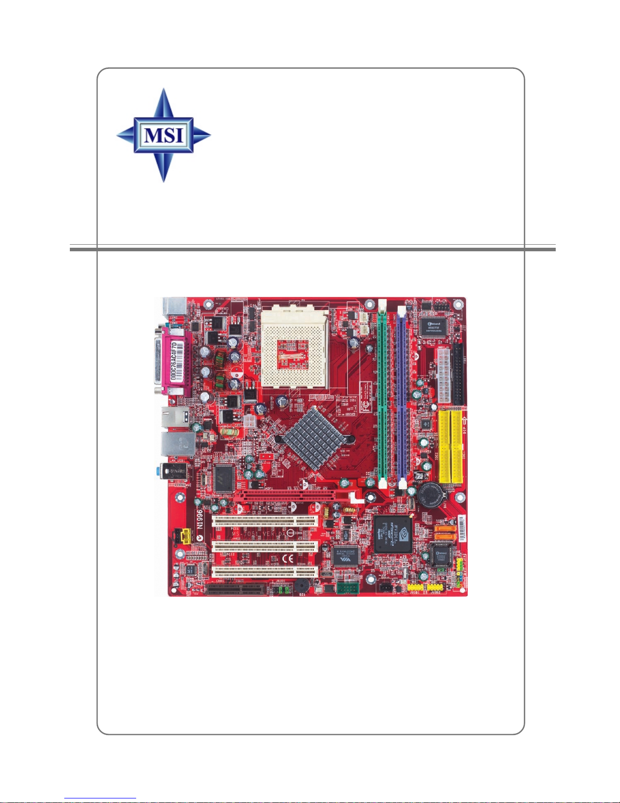
G52-M7051G1
MS-7051G (v1.X) M-ATX Mainboard
K7N2GM2 / K7N2M2 Series
Page 2
ii
Manual Rev: 1.0
Release Date: June 2004
FCC-B Radio Frequency Interference Statement
This equipment has been tested and found to comply with the limits for a class B
digital device, pursuant to part 15 of the FCC rules. These limits are designed to
provide reasonable protection against harmful interference when the equipment is
operated in a commercial environment. This equipment generates, uses and can
radiate radio frequency energy and, if not installed and used in accordance with the
instruction manual, may cause harmful interference to radio communications. Operation
of this equipment in a residential area is likely to cause harmful interference, in which
case the user will be required to correct the interference at his own expense.
Notice 1
The changes or modifications not expressly approved by the party responsible for
compliance could void the user’s authority to operate the equipment.
Notice 2
Shielded interface cables and A.C. power cord, if any, must be used in order to
comply with the emission limits.
VOIR LA NOTICE D’INSTALLATION A VANT DE RACCORDER AU RESEAU.
Micro-Star International
MS-7051G
This device complies with Part 15 of the FCC Rules. Operation is subject to the
following two conditions:
(1) this device may not cause harmful interference, and
(2) this device must accept any interference received, including interference that
may cause undesired operation
Page 3

iii
Copyright Notice
The material in this document is the intellectual property of MICRO-STAR
INTERNATIONAL. We take every care in the preparation of this document, but no
guarantee is given as to the correctness of its contents. Our products are under
continual improvement and we reserve the right to make changes without notice.
Trademarks
All trademarks are the properties of their respective owners.
AMD, Athlon™, Athlon™ XP, Thoroughbred™, and Duron™ are registered
trademarks of AMD Corporation.
Intel® and Pentium® are registered trademarks of Intel Corporation.
PS/2 and OS®/2 are registered trademarks of International Business Machines
Corporation.
Microsoft is a registered trademark of Microsoft Corporation. Windows® 98/2000/NT/
XP are registered trademarks of Microsoft Corporation.
NVIDIA, the NVIDIA logo, DualNet, and nForce are registered trademarks or trademarks of NVIDIA Corporation in the United States and/or other countries.
Netware® is a registered trademark of Novell, Inc.
Award® is a registered trademark of Phoenix Technologies Ltd.
AMI® is a registered trademark of American Megatrends Inc.
Kensington and MicroSaver are registered trademarks of the Kensington Technology
Group.
PCMCIA and CardBus are registered trademarks of the Personal Computer Memory
Card International Association.
Revision History
Revision Revision History Date
V1.0 First release for PCB 1.X June 2004
with nVidia nForce2 SPP/IGP
and nForce2 MCP RAID
Page 4

iv
1. Always read the safety instructions carefully.
2. Keep this User’s Manual for future reference.
3. Keep this equipment away from humidity.
4. Lay this equipment on a reliable flat surface before setting it up.
5. The openings on the enclosure are for air convection hence protects the equipment from overheating. Do not cover the openings.
6. Make sure the voltage of the power source and adjust properly 110/220V before connecting the equipment to the power inlet.
7. Place the power cord such a way that people can not step on it. Do not place
anything over the power cord.
8. Always Unplug the Power Cord before inserting any add-on card or module.
9. All cautions and warnings on the equipment should be noted.
10. Never pour any liquid into the opening that could damage or cause electrical
shock.
11. If any of the following situations arises, get the equipment checked by a service
personnel:
! The power cord or plug is damaged.
! Liquid has penetrated into the equipment.
! The equipment has been exposed to moisture.
! The equipment has not work well or you can not get it work according to
User’s Manual.
! The equipment has dropped and damaged.
! The equipment has obvious sign of breakage.
12. Do not leave this equipment in an environment unconditioned, storage
temperature above 600 C (1400F), it may damage the equipment.
Safety Instructions
CAUTION: Danger of explosion if battery is incorrectly replaced.
Replace only with the same or equivalent type recommended by the
manufacturer.
Technical Support
If a problem arises with your system and no solution can be obtained from the user’s
manual, please contact your place of purchase or local distributor. Alternatively,
please try the following help resources for further guidance.
! Visit the MSI homepage & FAQ site for technical guide, BIOS updates, driver
updates, and other information: http://www.msi.com.tw & http://www.msi.
com.tw/program/service/faq/faq/esc_faq_list.php
! Contact our technical staff at: support@msi.com.tw
Page 5

v
CONTENTS
FCC-B Radio Frequency Interference Statement ........................................................ ii
Copyright Notice ........................................................................................................... iii
Revision History............................................................................................................ iii
Technical Support ........................................................................................................ iv
Safety Instructions ...................................................................................................... iv
Chapter 1. Getting Started ................................................................................... 1-1
Mainboard Specifications .................................................................................. 1-2
Mainboard Layout ..............................................................................................1-5
Packing Contents ............................................................................................... 1-6
Chapter 2. Hardware Setup .................................................................................2-1
Quick Components Guide .................................................................................. 2-2
Central Processing Unit: CPU ............................................................................2-3
CPU Installation Procedures for Socket 462.............................................2-4
Installing AMD Athlon CPU Cooler Set........................................................ 2-5
Memory ............................................................................................................... 2-6
Introduction to DDR SDRAM....................................................................... 2-6
DIMM Module Combination .......................................................................... 2-7
Installing DDR Modules ............................................................................... 2-7
Power Supply..................................................................................................... 2-8
ATX 20-Pin Power Connector: JWR1 ........................................................2-8
ATX 12V Power Connector: JPW1............................................................ 2-8
Back Panel .......................................................................................................... 2-9
Mouse Connector .......................................................................................2-9
Keyboard Connector................................................................................2-10
VGA Connector ........................................................................................2-10
Serial Port Connector ............................................................................... 2-11
USB Connectors ....................................................................................... 2-11
IEEE 1394 Port........................................................................................... 2-11
LAN (RJ-45) Jack .....................................................................................2-12
Audio Port Connectors.............................................................................2-12
Parallel Port Connector: LPT1 ..................................................................2-13
Connectors ....................................................................................................... 2-14
Floppy Disk Drive Connector: FDD1 ........................................................2-14
Fan Power Connectors: CPU_FAN1/SYS_FAN1 ....................................2-14
Hard Disk Connectors: IDE1 & IDE2.........................................................2-15
Serial ATA HDD Connectors: SATA1&SATA2.........................................2-16
Aux Line-In Connector: AUX_IN1 ............................................................2-16
Page 6

vi
Front Panel Connectors: JFP1 & JFP2.....................................................2-17
CD-In Connector: JCD1 ............................................................................2-18
Front Panel Audio Connector: JAUD1 .....................................................2-18
Chassis Intrusion Switch Connector: JCI1 .............................................2-19
Front USB Connectors: JUSB1 & JUSB2 ................................................ 2-19
Serial Port Connector: JCOM2 .................................................................2-19
IEEE 1394 Connectors: J1394_1 .............................................................2-20
TV-Out Connector: JTV1..........................................................................2-21
SPDIF Connector: JSP1 ............................................................................ 2-22
Jumpers ............................................................................................................2-23
Clear CMOS Jumper: JBA T1 ....................................................................2-23
Slots ..................................................................................................................2-24
AGP (Accelerated Graphics Port) Slot ...................................................2-24
PCI (Peripheral Component Interconnect) Slots......................................2-24
CNR Slot ....................................................................................................2-24
PCI Interrupt Request Routing..................................................................2-24
Chapter 3. BIOS Setup........................................................................................... 3-1
Entering Setup .................................................................................................... 3-2
Control Keys ............................................................................................... 3-2
Getting Help ................................................................................................ 3-2
The Main Menu ................................................................................................... 3-3
Standard CMOS Features.................................................................................. 3-5
Advanced BIOS Features.................................................................................. 3-7
Advanced Chipset Features ...........................................................................3-10
Integrated Peripherals...................................................................................... 3-12
Power Management Setup ..............................................................................3-17
PNP/PCI Configurations ....................................................................................3-20
H/W Monitor ......................................................................................................3-22
Cell Menu ..........................................................................................................3-23
Load Fail-Safe/Optimized Defaults .................................................................3-27
Set Supervisor/User Password...................................................................... 3-28
Chapter 4. Introduction to DigiCell .................................................................... 4-1
Main ..................................................................................................................... 4-2
Communication ................................................................................................... 4-4
Software Access Point ..................................................................................... 4-5
Terminology ................................................................................................. 4-5
Access Point Mode ....................................................................................4-6
WLAN Card Mode .......................................................................................4-7
Page 7

vii
Live Update......................................................................................................... 4-8
MEGA STICK ....................................................................................................... 4-9
Basic Function ............................................................................................ 4-9
Non-Unicode programs supported .......................................................... 4-11
Audio Speaker Setting .....................................................................................4-13
Power on Agent ...............................................................................................4-15
Power On ..................................................................................................4-15
Power Off / Restart .................................................................................. 4-16
Start With ..................................................................................................4-16
Auto Login.................................................................................................4-17
Chapter 5. nVIDIA RAID Introduction ................................................................. 5-1
Introduction.................................................................................................................5-2
System Requirement .......................................................................................... 5-2
RAID Arrays........................................................................................................ 5-2
Summary of RAID Configurations ..................................................................... 5-2
RAID Configuration .................................................................................................... 5-3
Basic Configuration Instructions ....................................................................... 5-3
Setting Up the NVRAID BIOS .............................................................................5-3
NVIDIA RAID Untility Installation................................................................................. 5-7
Installing the NVIDIA RAID Software Under Windows
(for Non-bootable RAID Array) ..................................................... 5-7
Installing the RAID Driver (for bootable RAID Array) .......................................5-8
Initializing and Using the Disk Array ................................................................5-10
RAID Drives Management........................................................................................5-12
Viewing RAID Array Configurations ...............................................................5-12
Setting Up a Spare RAID Disk..........................................................................5-14
Rebuilding a RAID Mirrored Array ................................................................... 5-20
Page 8

1-1
Getting Started
Chapter 1. Getting
Started
Thank you for purchasing the K7N2GM2/K7N2M2 (MS-7051G
v1.X) Micro ATX mainboard. The K7N2GM2/K7N2M2 mainboard is
based on NVIDIA® nForce™2 SPP/IGP & NVIDIA® nForce™2 MCP
RAID for optimal system efficiency. Designed to fit the advanced
AMD® Athlon™, Athlon™ XP or Duron™ processors, the K7N2GM2/
K7N2M2 mainboard delivers a high performance and professional
desktop platform solution.
Getting Started
Page 9

1-2
MS-7051G M-ATX Mainboard
Mainboard Specifications
CPU
! Supports Socket A (Socket-462) for AMD Athlon/Athlon XP/Duron processors
! Supports FSB 400 Athlon XP processor from 1100 MHz up to 3200+ or above
(For the latest information about CPU, please visit http://www.msi.com.tw/program/
products/mainboard/mbd/pro_mbd_cpu_support.php)
Chipset
! NVIDIA® nForce2 SPP/nForce2 IGP
- FSB @266/333/400 MHz
- AGP 8X and PCI Advanced high performance memory controller
- Supports AGP 3.0 8x interface
- Integrated graphics controller (for nForce2 IGP only)
! NVIDIA nForce2 MCP RAID
- Integrated Faster Ethernet MAC
- Integrated Hardware Sound Blaster/Direct Sound AC97 audio
- Ultra DMA 66/100/133 master mode PCI EIDE controller
- Supports USB 2.0
- Integrated SATA Interface
Main Memory
! Supports two 64-bit wide DDR data channels
! Supports a maximum memory size up to 2GB
! Supports DDR 333 (for nForce2 IGP)/400 (for nForce2 SPP) memory module.
(For the updated supporting memory modules, please visit http://www.msi.com.tw/
program/products/mainboard/mbd/pro_mbd_trp_list.php.)
Slots
! One AGP (Accelerated Graphics Port) slot supports 8x/4x
! Three PCI 2.2 32-bit Master PCI Bus slots.
! Supports 3.3V/5V PCI bus Interface
USB Interface
! 8 USB ports
- Controlled by nForce2 MCP RAID southbridge
- 4 ports in the rear I/O, 4 ports via external bracket
On-Board IDE
! Two IDE controllers integrated on the nVIDIA nForce2 MCP RAID chipset providing
IDE HDD/CD-ROM with PIO, Bus Master and Ultra DMA66/100/133 operation modes
! Can connect up to four IDE devices
Page 10

1-3
Getting Started
On-Board Peripherals
! On-Board Peripherals include:
- 1 floppy port supports 1 FDD with 360K, 720K, 1.2M, 1.44M and 2.88Mbytes
- 2 serial ports/1VGA port
- 1 parallel port supports SPP/EPP/ECP mode
- audio ports in vertical
LAN
! Realtek 8201CL LAN PHY
- Supports 10/100Mb/s auto-negotiation operation
On-Board 1394 (optional)
! VIA VT6307
Audio
! 5.1 channels S/W audio codec Realtek ALC655 codec
- Compliance with AC97 2.3 Spec
- Meets PC2001 audio performance requirement
SATA Interface
! Integrated SATA Phy, supporting up to 2 ports
! One SATA controller, supporting two drives in master mode
A TTENTION!!!
Please note that users cannot install OS, either WinME or Win98, in
their SATA hard drive. Under these two OSs, SATA can only be
used as a normal storage device.
Page 11

1-4
MS-7051G M-ATX Mainboard
NV RAID (Software)
! Supports 2 serial ATA plus 4 parallel ATA
- RAID 1, or 1, 0+1, JBOD is supported
- Booting from RAID
- Cross controller RAID support
- Rebuilding on the Fly
- Spare Disk Allocation
! Supports Windows 2000 and later versions
BIOS
! The mainboard BIOS provides “Plug & Play” BIOS which detects the peripheral
devices and expansion cards of the board automatically.
! The mainboard provides a Desktop Management Interface (DMI) function which
records your mainboard specifications.
Dimension
! Micro-ATX Form Factor: 24.4 cm (L) x 24.4 cm (W)
Mounting
! 8 mounting holes
Others
! Suspend to RAM/Disk (S3/S4)
A TTENTION!!!
To create a bootable RAID volume for a Windows 2000 environment,
Microsoft’s Windows 2000 Service Pack 4 (SP4) is required. As
the end user cannot boot without SP4, a combination installation
CD must be created before attempting to install the operating system onto the bootable RAID volume.
To create the combination installation CD, please refer to the following website:
http://www.microsoft.com/windows2000/
downloads/servicepacks/sp4/HFdeploy.htm
Page 12
1-5
Getting Started
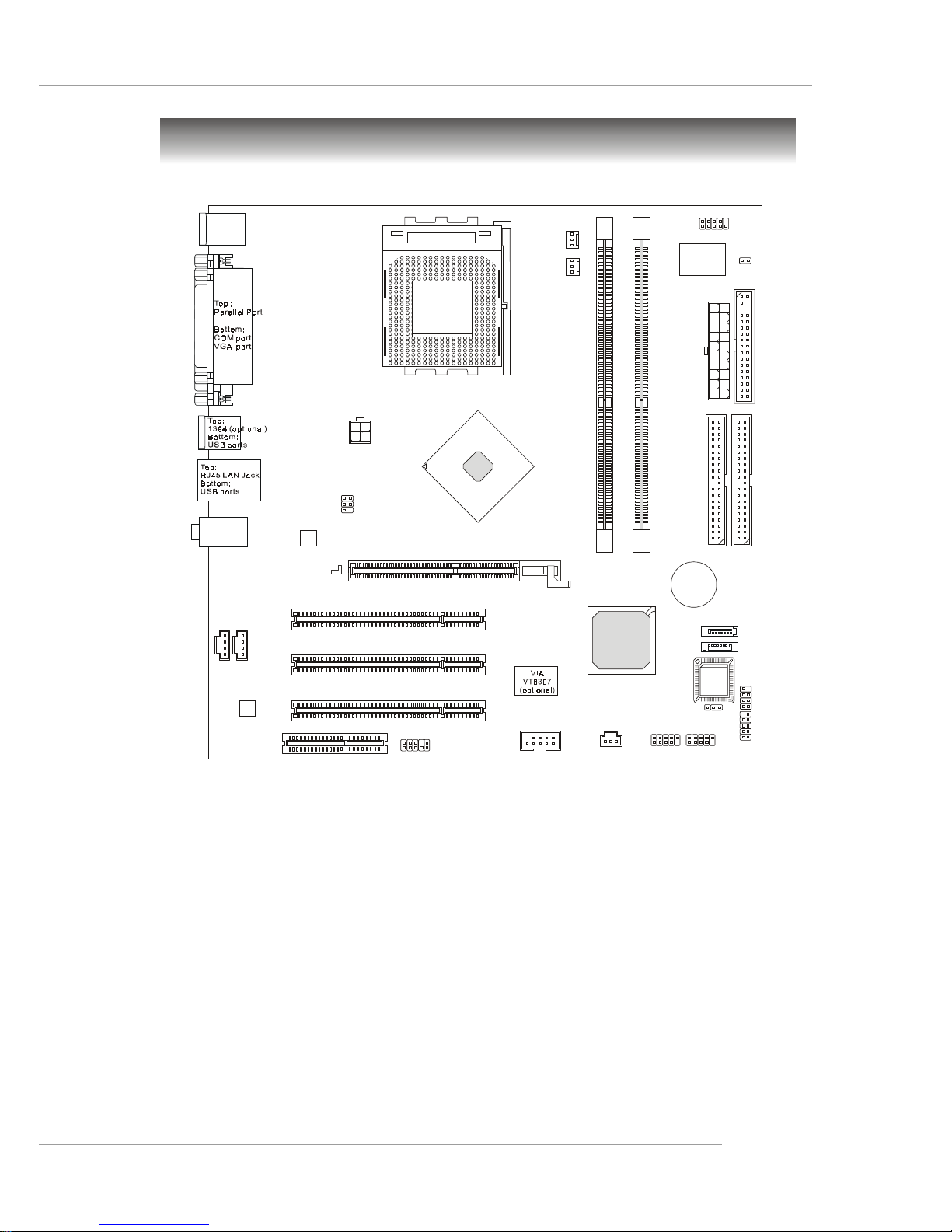
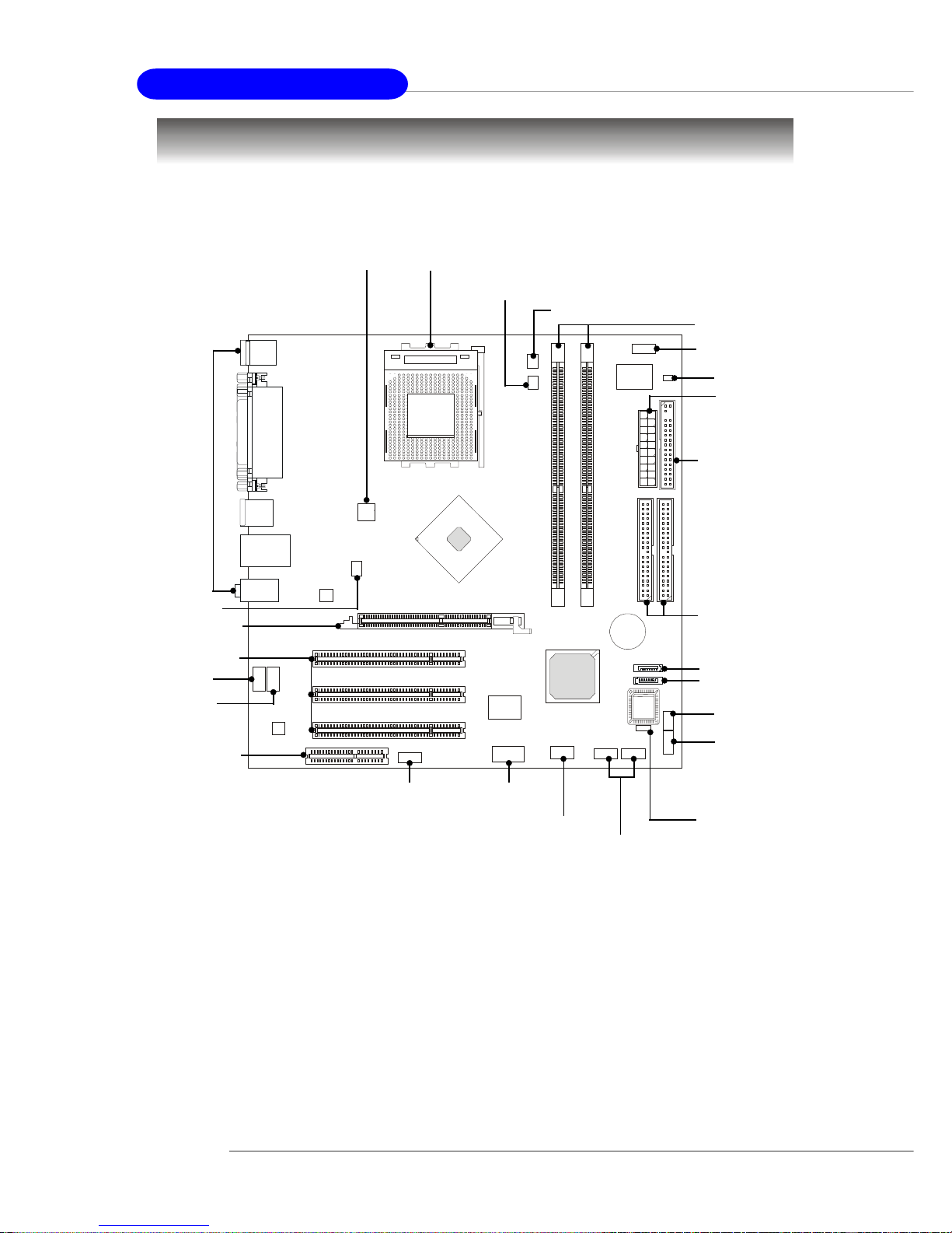
Mainboard Layout
K7N2GM2/K7N2M2 Series (MS-7051G v1.X)
Micro-ATX Mainboard
D
I
M
M
2
D
I
M
M
1
AGP Slot
Top: mouse
Bottom: keyboard
Top:
Line-Out
Bottom:Mic
Line-In
Middle:
JAUD1
AUX_IN1
JCD1
JSP1
Codec
REALTEK
RTL8201CL
B
A
T
T
+
BIOS
Winbond
W83627THF
NVIDIA
nFORCE 2
MCP
RAID
I
D
E
1
I
D
E
2
FDD1
JCOM2
PCI Slot 1
PCI Slot 2
PCI Slot 3
CPU_FAN1
SYS_FAN1
JFP1
JFP2
JPW1
A
T
X
P
o
w
e
r
S
u
p
p
l
y
JBAT1
JCI1
JTV1
JUSB1
SATA2
SATA1
JUSB2
CNR1
J1394_1 (optional)
SOCKET 462
Page 13
1-6
MS-7051G M-ATX Mainboard
Packing Contents
Power Cable
SATA Cable (Optional)
User’s Guide
MSI motherboard
MSI Driver/Utility CD
Round Cable of
IDE Devices
Round Cable of
Floppy Disk
Back IO Shield
Page 14

2-1
Hardware Setup
Chapter 2. Hardware Setup
This chapter tells you how to install the CPU, memory modules,
and expansion cards, as well as how to setup the jumpers on the
mainboard. Also, it provides the instructions on connecting the peripheral devices, such as the mouse, keyboard, etc.
While doing the installation, be careful in holding the components and follow the installation procedures.
Hardware Setup
Page 15
2-2
MS-7051G M-ATX Mainboard
SOCKET 462
Quick Components Guide
JBAT1, p.2-23
DDR DIMMs, p.2-6
CPU, p.2-3
CPU_FAN1, p.2-14
FDD1, p.2-14
IDE1/2, p.2-15
JUSB1/2,
p.2-19
JAUD1,
p.2-18
JPW1, p.2-8
SYS_FAN1, p.2-14
Back Panel
I/O, p.2-9
JTV1, p.2-21
CNR slot, p.2-24
AGP slot, p.2-24
PCI slots, p.2-24
JCD1, p.2-18
AUX_IN1,
p.2-16
J1394_1,
p.2-20
(optional)
JSP1,
p.2-22
JFP1, p.2-17
SATA1, p.2-16
SATA2, p.2-16
JWR1, p.2-8
JCI1, p.2-19
JCOM2, p.2-19
JFP2, p.2-17
Page 16

2-3
Hardware Setup
Central Processing Unit: CPU
MSI Reminds You...
Overheating
Overheating will seriously damage the CPU and system, always make
sure the cooling fan can work properly to protect the CPU from
overheating.
Replacing the CPU
While replacing the CPU, always turn off the ATX power supply or
unplug the power supply’s power cord from grounded outlet first to
ensure the safety of CPU.
Overclocking
This motherboard is designed to support overclocking. However,
please make sure your components are able to tolerate such abnormal setting, while doing overclocking. Any attempt to operate beyond
product specifications is not recommended. We do not guarantee
the damages or risks caused by inadequate operation or beyond product specifications.
The mainboard supports AMD® Athlon™, Athlon™ XP and Duron™ processors
in the 462 pin package. The mainboard uses a CPU socket called Socket A for easy
CPU installation. When you are installing the CPU, make sure the CPU has a heat
sink and a cooling fan attached on the top to prevent overheating. If you do
not find the heat sink and cooling fan, contact your dealer to purchase and install
them before turning on the computer.
For the latest information about CPU, please visit http://www.msi.com.tw/
program/products/mainboard/mbd/pro_mbd_cpu_support.php.
CPU Core Speed Derivation Procedure
CPU Clock multiplied by Core/Bus ratio equals the CPU core speed.
For example:
If CPU Clock = 100MHz
Core/Bus ratio = 14
then CPU core speed = Host Clock x Core/Bus ratio
= 100MHz x 14
= 1.4 GHz
Page 17
2-4
MS-7051G M-ATX Mainboard
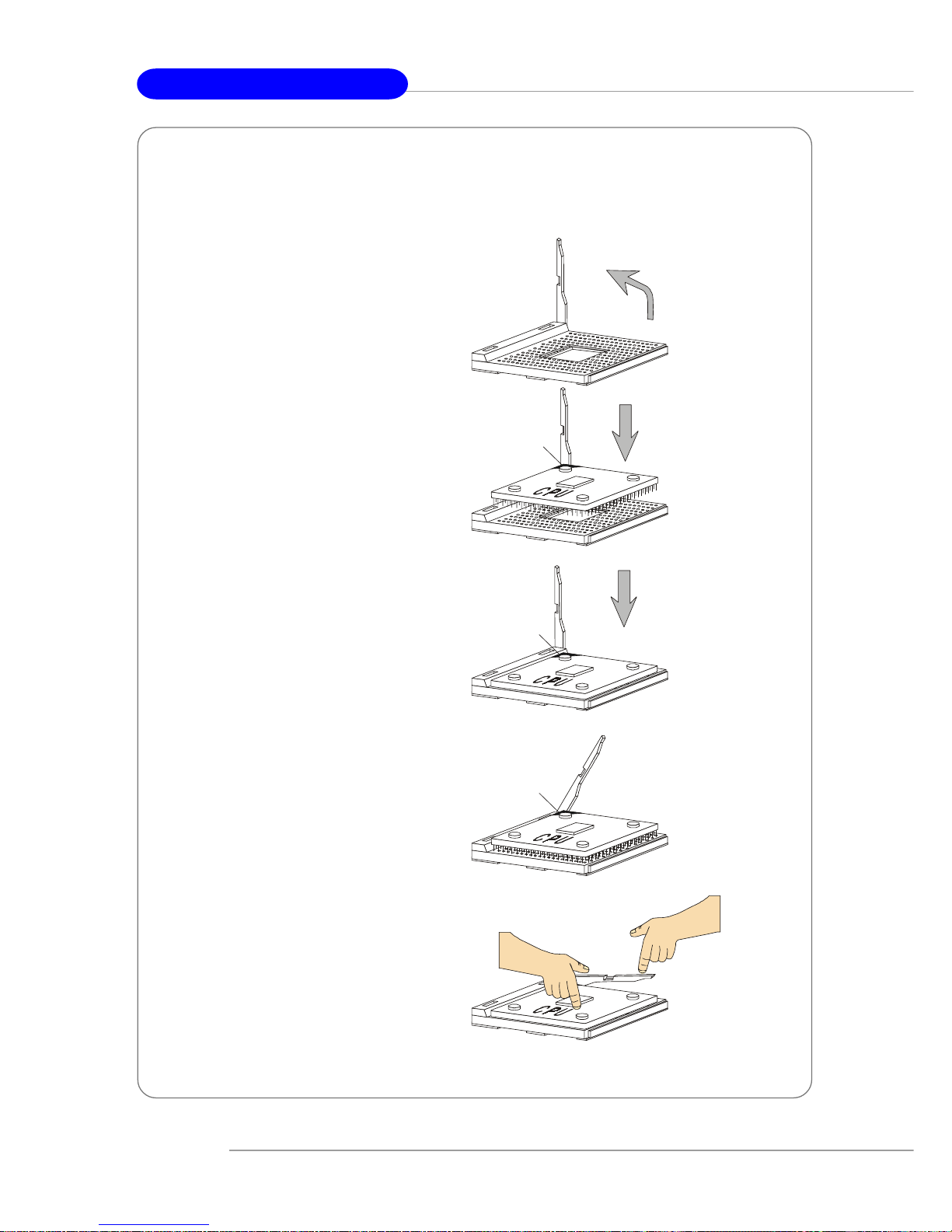
1. Please turn off the power and
unplug the power cord before
installing the CPU.
2. Pull the lever sideways away
from the socket. Make sure to
raise the lever up to a 90-degree
angle.
3. Look for the gold arrow. The gold
arrow should point towards the
lever pivot. The CPU can only fit
in the correct orientation.
4. If the CPU is correctly installed,
the pins should be completely
embedded into the socket and
can not be seen. Please note
that any violation of the correct
installation procedures may
cause permanent damages to
your mainboard.
5. Press the CPU down firmly into
the socket and close the lever.
As the CPU is likely to move while
the lever is being closed,
always close the lever with your
fingers pressing tightly on top of
the CPU to make sure the CPU is
properly and completely
embedded into the socket.
CPU Installation Procedures for Socket 462
Open Lever
Gold arrow
Gold arrow
90 degree
Correct CPU placement
Incorrect CPU placement
Gold arrow
Sliding
Plate
Close
Lever
Press down
the CPU
X
O
Page 18
2-5
Hardware Setup
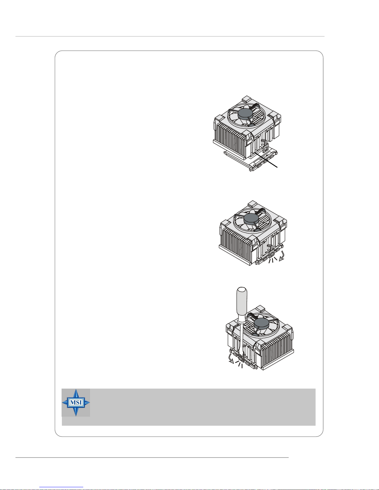
The following instructions will guide you
through the heat sink installation
procedures. Please consult your agent
for the proper CPU cooler set.
1. Position your CPU cooler set onto the
CPU.
2. Use one end of the clip to hook the
latch of the CPU sliding plate.
3. Hook the other latch to fix the cooling
fan set. You may need a screw
drive to press down the other side
of the clip.
4. Connect the fan to the power supply
connector provided on your
mainboard.
Installing AMD Athlon CPU (Socket 462) Cooler Set
Apply some heat
sink paste
MSI Reminds You...
Please apply some heat sink paste on top of CPU to dissipate the heat
more effectively.
Page 19
2-6
MS-7051G M-ATX Mainboard
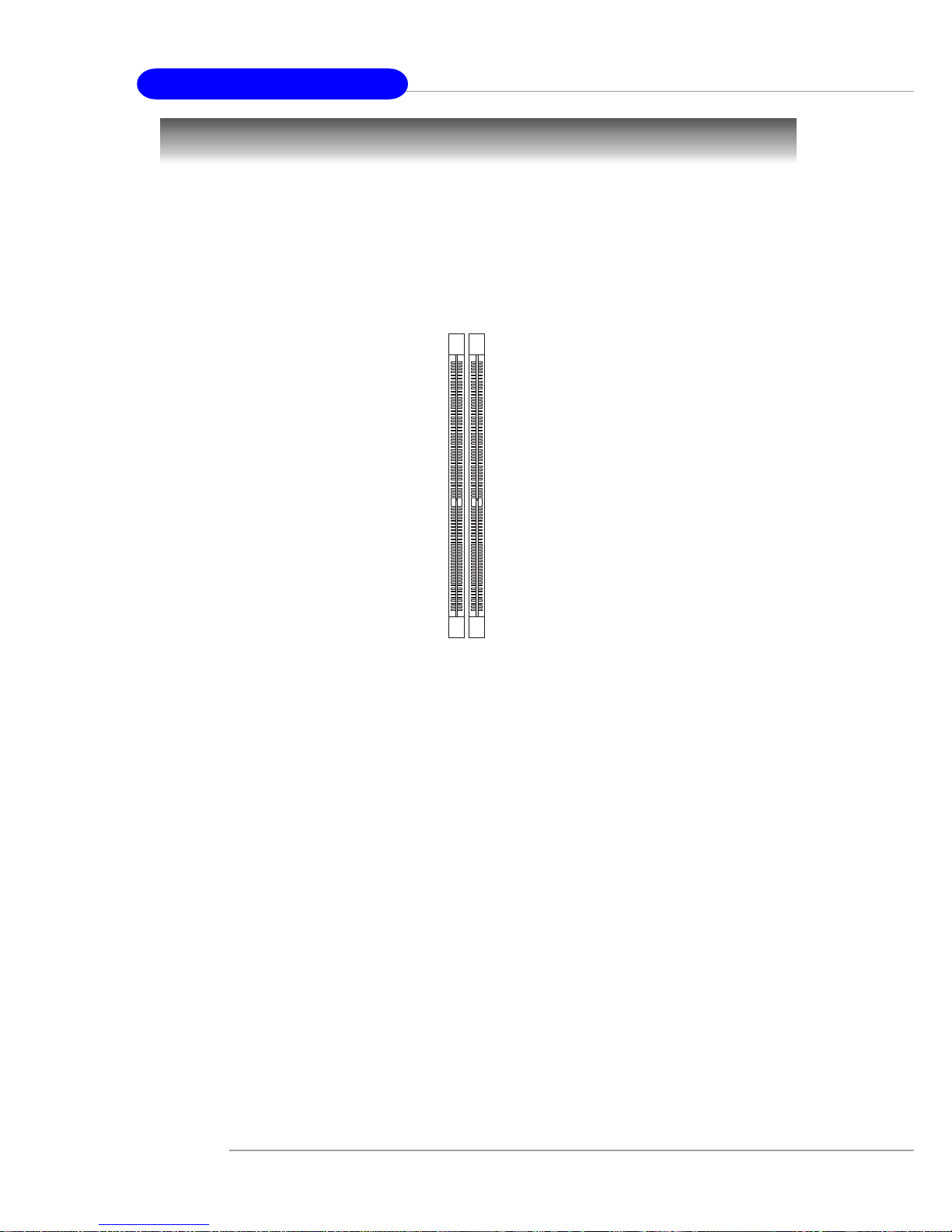
Memory
The mainboard provides 2 slots for 184-pin DDR SDRAM DIMM (Double In-Line Memory
Module) modules and supports the memory size up to 2GB. You can install DDR266/
333/400 modules on the DDR DIMM slots (DDR 1~2).
For the updated supporting memory modules, please visit http://www.msi.com.tw/
program/products/mainboard/mbd/pro_mbd_trp_list.php.
DDR DIMM Slots
(DDR 1~2)
Introduction to DDR SDRAM
DDR (Double Data Rate) SDRAM is similar to conventional SDRAM, but doubles the
rate by transferring data twice per cycle. It uses 2.5 volts as opposed to 3.3 volts
used in SDR SDRAM, and requires 184-pin DIMM modules rather than 168-pin DIMM
modules used by SDR SDRAM.
Page 20
2-7
Hardware Setup
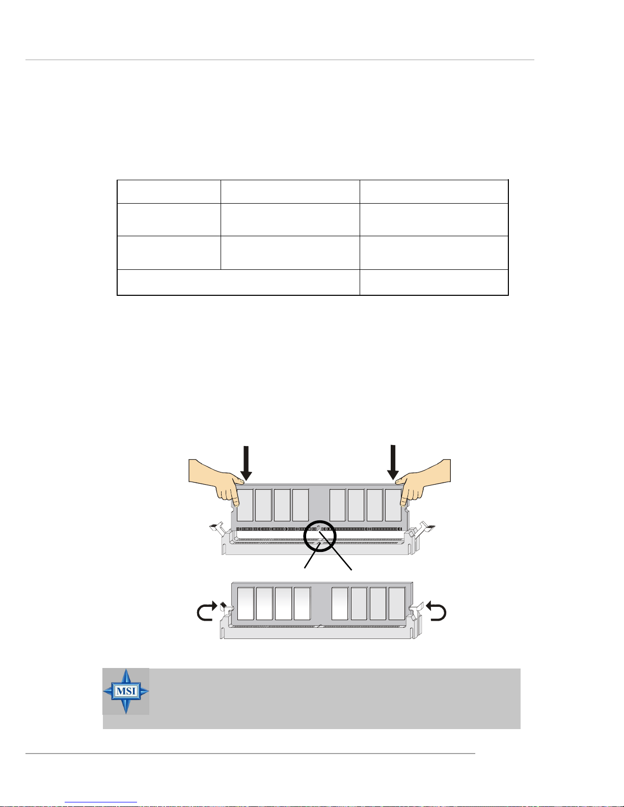
Installing DDR Modules
1. The DDR DIMM has only one notch on the center of module. The module will
only fit in the right orientation.
2. Insert the DIMM memory module vertically into the DIMM slot. Then push it in
until the golden finger on the memory module is deeply inserted in the socket.
3. The plastic clip at each side of the DIMM slot will automatically close.
MSI Reminds You...
You can barely see the golden finger if the module is properly inserted in the socket.
DIMM Module Combination
Install at least one DIMM module on the slots. You can install either single- or doublesided modules in any order to meet your own needs.
Memory modules can be installed in any combination as follows:
S: Single Side D: Double Side
Slot Memory Module T otal Memory
DDR 2
(Bank 2 & 3) S/D 64MB~1GB
Maximum System Memory Supported 64MB~2GB
DDR 1
(Bank 0 & 1) S/D 64MB~1GB
Volt
Notch
Page 21

2-8
MS-7051G M-ATX Mainboard
Power Supply
The mainboard supports ATX power supply for the power system. Before inserting
the power supply connector, always make sure that all components are installed
properly to ensure that no damage will be caused.
ATX 20-Pin Power Connector: JWR1
This connector allows you to connect to an ATX power supply. To connect to the ATX
power supply, make sure the plug of the power supply is inserted in the proper
orientation and the pins are aligned. Then push down the power supply firmly into the
connector.
MSI Reminds You...
1. These two connectors connect to the ATX power supply and have to
work together to ensure stable operation of the mainboard.
2. Power supply of 300 (and up) watt is highly recommended for system
stability.
PIN SIGNAL
11 3.3V
12 -12V
13 GND
14 PS_ON
15 GND
16 GND
17 GND
1 8 -5V
19 5V
20 5V
PIN SIGNAL
1 3.3V
2 3.3V
3 GND
45V
5 GND
65V
7 GND
8 PW_OK
9 5V_SB
10 12V
JWR1 Pin Definition
JWR1
10
1
20
11
PIN SIGNAL
1 GND
2 GND
312V
412V
JPW1 Pin Definition
JPW1
1
3
2
4
ATX 12V Power Connector: JPW1
This 12V power connector is used to provide power to the CPU.
Page 22
2-9
Hardware Setup
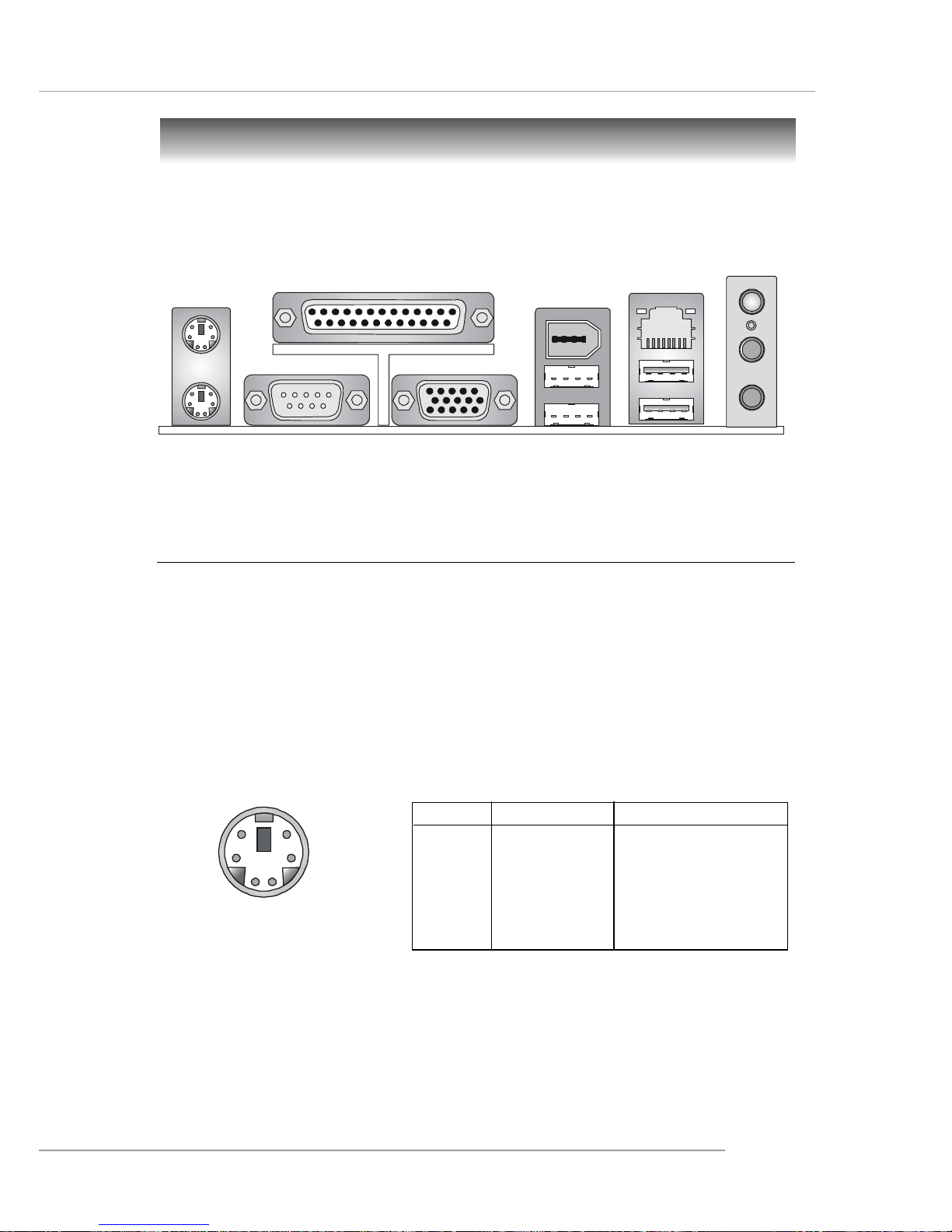
The back panel provides the following connectors:
Back Panel
Mouse
Printer Port
USB Ports
Keyboard
MIC
LAN
VGA Port
USB Ports
1394
(optional)
COM Port
L-in
L-out
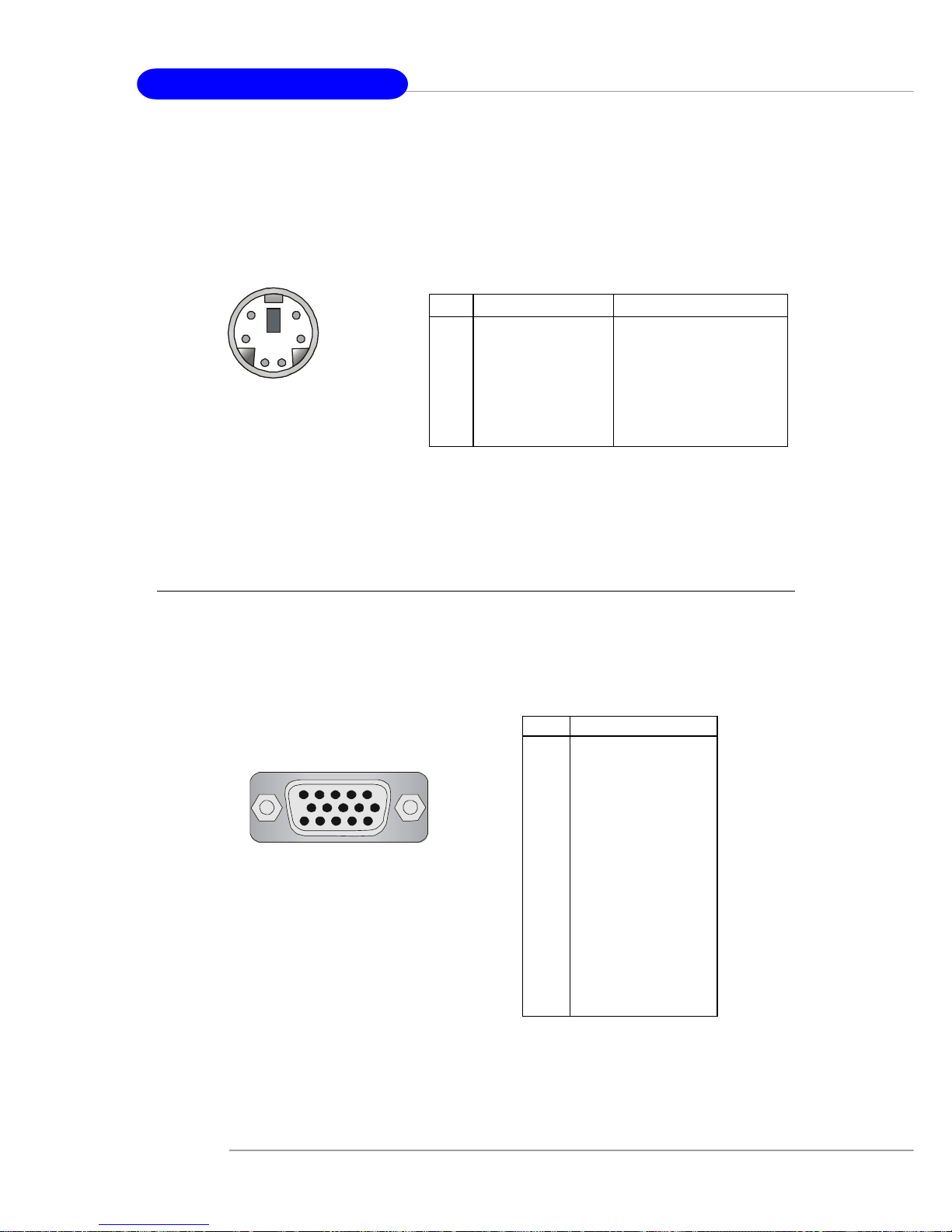
Mouse Connector
The mainboard provides a standard PS/2® mouse mini DIN connector for attaching a
PS/2® mouse. You can plug a PS/2® mouse directly into this connector. The connector location and pin assignments are as follows:
PIN SIGNAL DESCRIPTION
1 Mouse DA T A Mouse DAT A
2 NC No connection
3 GND Ground
4 VCC +5V
5 Mouse Clock Mouse clock
6 NC No connection
Pin Definition
PS/2 Mouse (6-pin Female)
2
1
3
4
5
6
Page 23
2-10
MS-7051G M-ATX Mainboard
PS/2 Keyboard
(6-pin Female)
2
1
3
4
5
6
PIN SIGNAL DESCRIPTION
1 Mouse/Keyboard Data Mouse/Keyboard data
2 NC No connection
3 GND Ground
4 VCC +5V
5 Mouse/Keyboard Clock Mouse/Keyboard clock
6 NC No connection
Pin Definition
VGA Connector:
The mainboard provides a DB 15-pin female connector to connect a VGA monitor.
Keyboard Connector
The mainboard provides a standard PS/2® keyboard mini DIN connector for attaching
a PS/2® keyboard. You can plug a PS/2® keyboard directly into this connector.
VGA Connector, DB 15-pin
1
5
11
15
Pin Signal Description
1 RED
2 GREEN
3 BLUE
4 N/C
5 GND
6 GND
7 GND
8 GND
9 +5V
10 GND
1 1 N/C
12 SDA
13 Horizontal Sync
14 Vertical Sync
15 SCL
Page 24
2-11
Hardware Setup
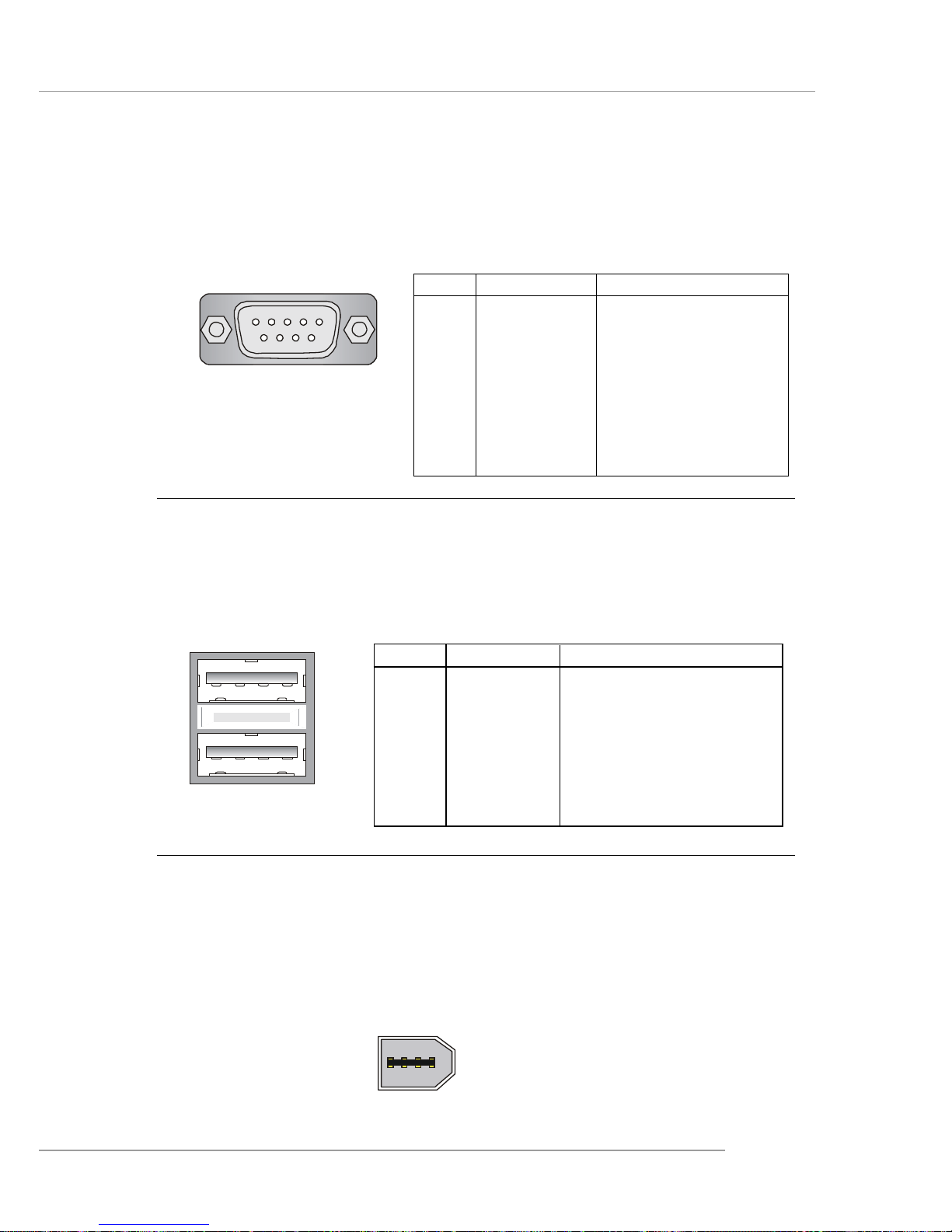
Serial Port Connector:
The mainboard offers one 9-pin male DIN connector as the serial port. The port is a
16550A high speed communication port that sends/receives 16 bytes FIFOs. Yo u
can attach a serial mouse or other serial devices directly to the connector.
USB Connectors
The mainboard provides an OHCI (Open Host Controller Interface) Universal Serial
Bus root for attaching USB devices such as keyboard, mouse or other USB-compatible devices. You can plug the USB device directly into the connector.
USB Ports
1 2 3 4
5 6 7 8
PIN SIGNAL DESCRIPTION
1 VCC +5V
2 -Data 0 Negative Data Channel 0
3 +Data0 Positive Data Channel 0
4 GND Ground
5 VCC +5V
6 -Data 1 Negative Data Channel 1
7 +Data 1 Positive Data Channel 1
8 GND Ground
USB Port Description
PIN SIGNAL DESCRIPTION
1 DCD Data Carry Detect
2 SIN Serial In or Receive Data
3 SOUT Serial Out or Transmit Data
4 DTR Data T erminal Ready)
5 GND Ground
6 DSR Data Set Ready
7 RTS Request To Send
8 CTS Clear To Send
9 RI Ring Indicate
Pin Definition
(9-Pin Male DIN Connector)
1 2 3 4 5
6 7 8 9
COM port
IEEE 1394 Port (optional)
The back panel provides one standard IEEE 1394 port. The standard IEEE 1394 port
connects to IEEE 1394 devices without external power. The IEEE 1394 high-speed
serial bus complements USB by providing enhanced PC connectivity for a wide range
of devices, including consumer electronics audio/video (A/V) appliances, storage
peripherals, other PCs, and portable devices.
1394 Port
Page 25

2-12
MS-7051G M-ATX Mainboard
LAN (RJ-45) Jack
The mainboard provides one standard RJ-45 jack for connection to Local Area Network (LAN). You can connect a network cable to the LAN jack.
Giga-bit LAN Pin Definition
PIN SIGNAL DESCRIPTION
1 D0 P Differential Pair 0+
2 D0N Differential Pair 03 D1 P Differential Pair 1+
4 D2 P Differential Pair 2+
5 D2N Differential Pair 26 D1N Differential Pair 17 D3 P Differential Pair 3+
8 D3N Differential Pair 3-
RJ-45 LAN Jack
MSI Reminds You...
For advanced audio application, Realtek ALC 655 is provided to
offer support for 6-channel audio operation and can turn rear
audio connectors from 2-channel to 4-/6-channel audio. For more
information on 6-channel audio operation , please refer to
Appendix. Using 4- or 6-Channel Audio Function.
Audio Port Connectors
Line Out is a connector for Speakers or Headphones. Line In is used for external
CD player, Tape player, or other audio devices. Mic is a connector for microphones.
1/8” Stereo Audio Connectors
Line Out
Line In
MIC
Page 26
2-13
Hardware Setup
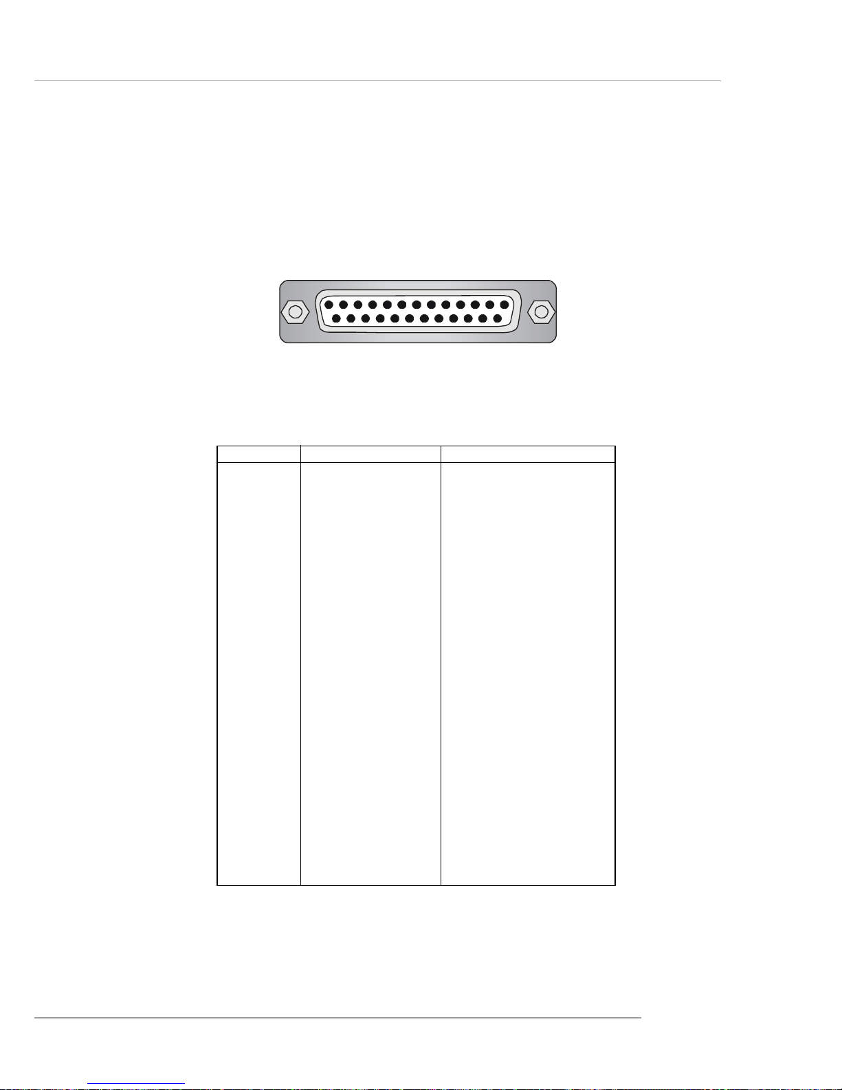
Parallel Port Connector: LPT1
The mainboard provides a 25-pin female centronic connector as LPT. A parallel port
is a standard printer port that supports Enhanced Parallel Port (EPP) and Extended
Capabilities Parallel Port (ECP) mode.
13 1
14
25
PIN SIGNAL DESCRIPTION
1 STROBE Strobe
2 DA T A0 Data0
3 DA T A1 Data1
4 DA T A2 Data2
5 DA T A3 Data3
6 DA T A4 Data4
7 DA T A5 Data5
8 DA T A6 Data6
9 DA T A7 Data7
10 ACK# Acknowledge
11 BUSY Busy
12 PE Paper End
1 3 SELECT Select
1 4 AUTO FEED# Automatic Feed
15 ERR# Error
1 6 INIT# Initialize Printer
17 SLIN# Select In
18 GND Ground
19 GND Ground
20 GND Ground
21 GND Ground
22 GND Ground
23 GND Ground
24 GND Ground
25 GND Ground
Pin Definition
Page 27
2-14
MS-7051G M-ATX Mainboard
The mainboard provides connectors to connect to FDD, IDE HDD, case, LAN, USB
Ports and CPU/System FAN.
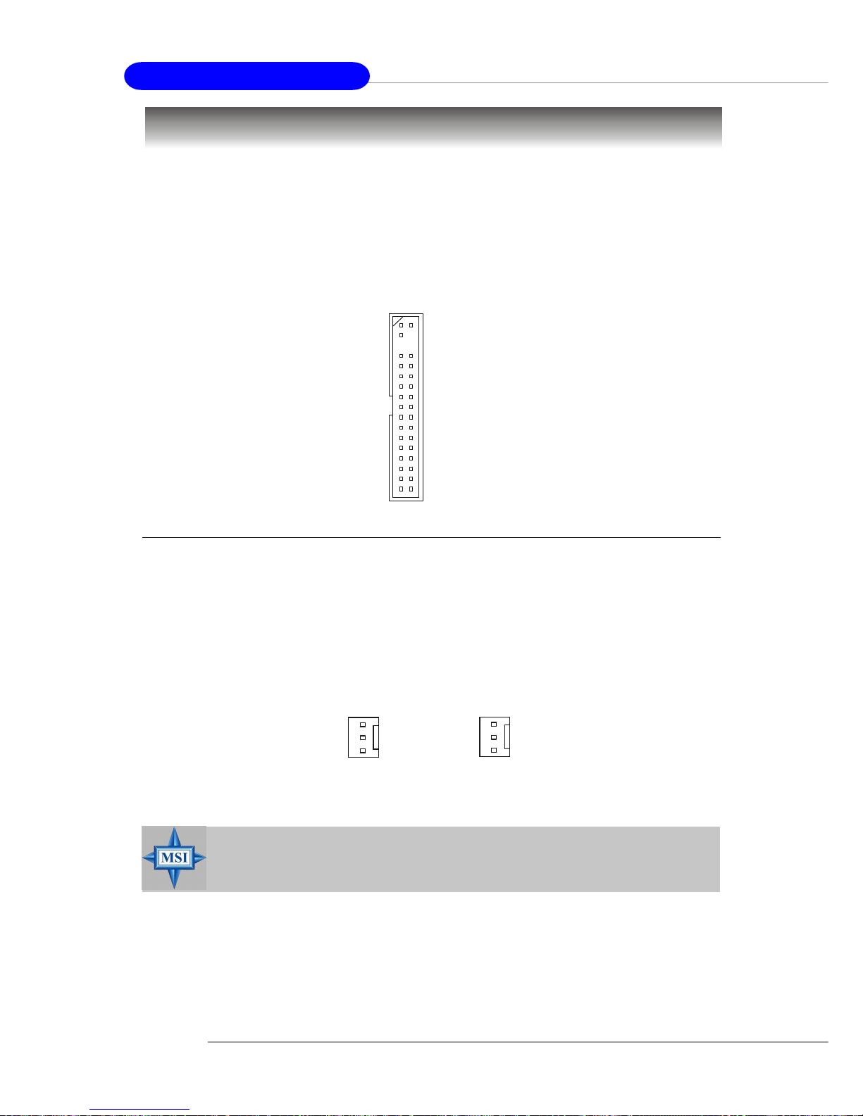
Floppy Disk Drive Connector: FDD1
The mainboard provides a standard floppy disk drive connector that supports 360K,
720K, 1.2M, 1.44M and 2.88M floppy disk types.
Connectors
Fan Power Connectors: CPU_F AN1 & SYS_F AN1
The CPU_FAN1 (processor fan) and SYS_FAN1 (system fan 1) support system
cooling fan with +12V. It supports three-pin head connector. When connecting the
wire to the connectors, always take note that the red wire is the positive and should
be connected to the +12V, the black wire is Ground and should be connected to GND.
If the mainboard has a System Hardware Monitor chipset on-board, you must use a
specially designed fan with speed sensor to take advantage of the CPU fan control.
MSI Reminds You...
1. Always consult the vendors for proper CPU cooling fan.
2. Please refer to the recommend CPU fans at AMD® official website.
CPU_F AN1
Sensor
+12V
GND
SYS_FAN1
Sensor
+12V
GND
FDD1
Page 28
2-15
Hardware Setup
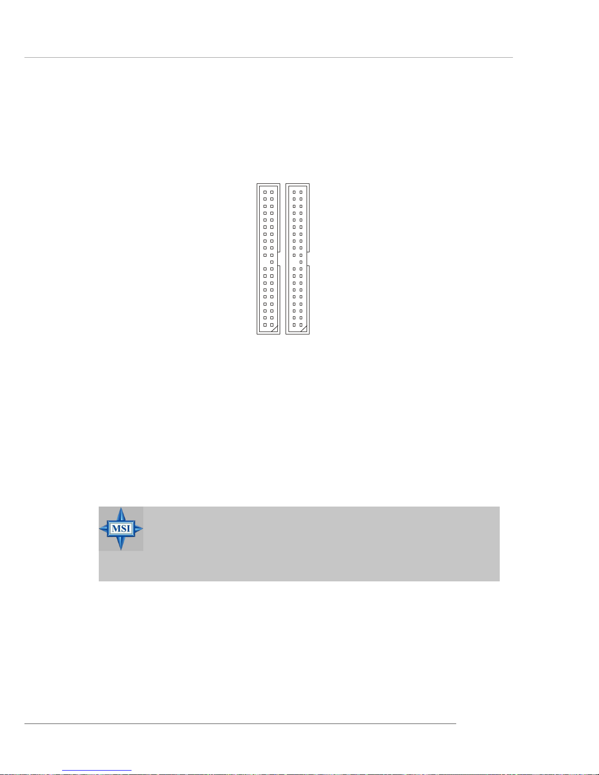
Hard Disk Connectors: IDE1 & IDE2
The mainboard has a 32-bit Enhanced PCI IDE and Ultra DMA 33/66/100/133 controller
that provides PIO mode 0~4, Bus Master, and Ultra DMA 33/66/100/133 function. You
can connect up to four hard disk drives, CD-ROM, 120MB Floppy (reserved for future
BIOS) and other devices.
IDE1 (Primary IDE Connector)
The first hard drive should always be connected to IDE1. IDE1 can connect a Master
and a Slave drive. You must configure second hard drive to Slave mode by setting the
jumper accordingly.
IDE2 (Secondary IDE Connector)
IDE2 can also connect a Master and a Slave drive.
IDE1IDE2
MSI Reminds You...
If you install two hard disks on cable, you must configure the second
drive to Slave mode by setting its jumper. Refer to the hard disk
documentation supplied by hard disk vendors for jumper setting
instructions.
Page 29
2-16
MS-7051G M-ATX Mainboard
Aux Line-In Connector: AUX_IN1
The connector is for DVD add-on card with Line-in connector.
GND
R
L
AUX_IN1
MSI Reminds You...
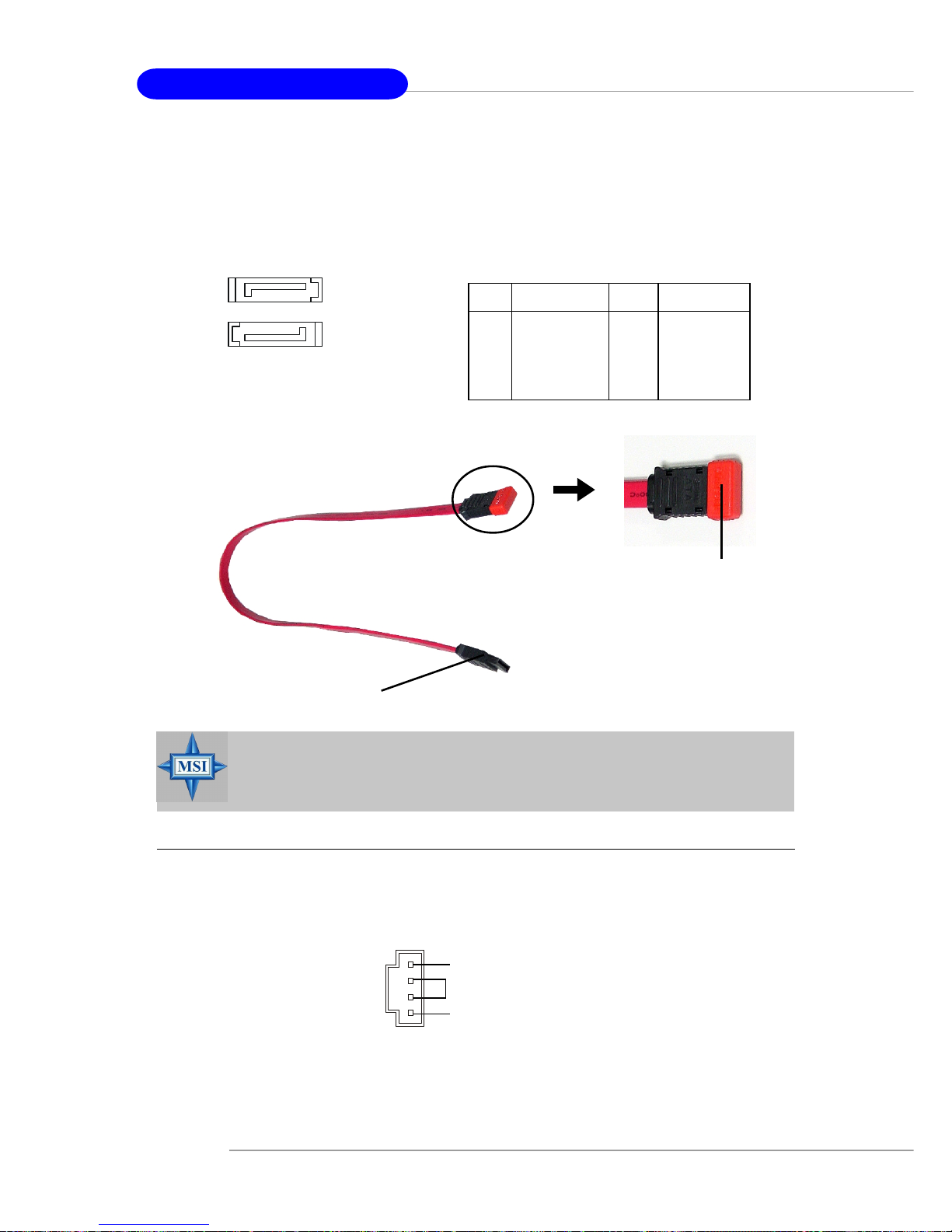
Please do not fold the serial ATA cable in a 90-degree angle, which will
cause the loss of data during the transmission.
Connect to serial ATA ports
Take out the dust cover and
connect to the hard disk
devices
Serial A TA cable
PIN SIGNAL PIN SIGNAL
1 GND 2 TXP
3 TXN 4 GND
5 RXN 6 RXP
7 GND
SA TA1/SA T A2 Pin Definition
7
1
SATA2
SATA1
1
7
Serial A TA HDD Connectors: SA TA1 & SA TA2
The mainboard provides dual high-speed Serial ATA interface ports. The ports support 1st generation Serial ATA data rates of 150MB/s and are fully compliant with
Serial ATA 1.0 specifications. Each Serial ATA connector can connect to 1 hard disk
drive.
Page 30
2-17
Hardware Setup
Front Panel Connectors: JFP1 & JFP2
The mainboard provides two front panel connectors for electrical connection to the
front panel switches and LEDs. JFP1 is compliant with Intel® Front Panel I/O Connectivity Design Guide.
PIN SIGNAL DESCRIPTION
1 HD_LED_P Hard disk LED pull-up
2 FP PWR/SLP MSG LED pull-up
3 HD_LED_N Hard disk active LED
4 FP PWR/SLP MSG LED pull-up
5 RST_SW_N Reset Switch low reference pull-down to GND
6 PWR_SW_P Power Switch high reference pull-up
7 RST_SW_P Reset Switch high reference pull-up
8 PWR_SW_N Power Switch low reference pull-down to GND
9 RSVD_DNU Reserved. Do not use.
JFP1 Pin Definition
PIN SIGNAL PIN SIGNAL
1 GND 2 SPK3 SLED 4 BUZ+
5 PLED 6 BUZ7 NC 8 SPK+
JFP2 Pin Definition
JFP2
7
8
Power
LED
Speaker
12
JFP1
1
2
910
HDD
LED
Reset
Switch
Power
LED
Power
Switch
Page 31

2-18
MS-7051G M-ATX Mainboard
Front Panel Audio Connector: JAUD1
The JAUD1 front panel audio connector allows you to connect to the front panel
audio and is compliant with Intel® Front Panel I/O Connectivity Design Guide.
PIN SIGNAL DESCRIPTION
1 AUD_MIC Front panel microphone input signal
2 AUD_GND Ground used by analog audio circuits
3 AUD_MIC_BIAS Microphone power
4 AUD_VCC Filtered +5V used by analog audio circuits
5 AUD_FPOUT_R Right channel audio signal to front panel
6 AUD_RET_R Right channel audio signal return from front panel
7 HP_ON Reserved for future use to control headphone amplifier
8 KE Y No pin
9 AUD_FPOUT_L Left channel audio signal to front panel
1 0 AUD_RET_L Left channel audio signal return from front panel
Pin Definition
JAUD1
1
2
9
10
MSI Reminds You...
If you don’t want to connect to the front audio header,
pins 5 & 6, 9 & 10 have to be jumpered in order to have
signal output directed to the rear audio ports. Otherwise,
the Line-Out connector on the back panel will not
function.
5
6
10
9
CD-In Connector: JCD1
The connector is for CD-ROM audio connector.
JCD1
GND
R
L
Page 32

2-19
Hardware Setup
PIN SIGNAL DESCRIPTION
1 DCD Data Carry Detect
2 SIN Serial In or Receive Data
3 SOUT Serial Out or Transmit Data
4 DTR Data T erminal Ready)
5 GND Ground
6 DSR Data Set Ready
7 RTS Request To Send
8 CTS Clear To Send
9 RI Ring Indicate
Pin Definition
Serial Port Connector: JCOM2
The mainboard offers another serial port JCOM2. It is 16550A high speed communication ports that sends/receives 16 bytes FIFOs. You can attach a serial mouse or other
serial device directly to it.
JCOM2
10
9
2
1
Chassis Intrusion Switch Connector: JCI1
This connector is connected to a 2-pin chassis switch. If the chassis is opened,
the switch will be short. The system will record this status and show a warning
message on the screen. To clear the warning, you must enter the BIOS utility and
clear the record.
JCI1
2
GND
CINTRU
1
Front USB Connectors: JUSB1 & JUSB2
The mainboard provides two USB 2.0 pin headers JUSB1/JUSB2 that are compliant
with Intel® I/O Connectivity Design Guide. USB 2.0 technology increases data transfer
rate up to a maximum throughput of 480Mbps, which is 40 times faster than USB 1.
1, and is ideal for connecting high-speed USB interface peripherals such as USB
HDD, digital cameras , MP3 players, printers, modems and the like .
PIN SIGNAL PIN SIGNAL
1 VCC 2 VCC
3 USB0- 4 USB15 USB0+ 6 USB1+
7 GND 8 GND
9 Key 10 NC
JUSB1/JUSB2 Pin Definition
JUSB1/JUSB2
(USB 2.0/Intel spec)
1
2
9
10
Page 33

2-20
MS-7051G M-ATX Mainboard
IEEE 1394 Connectors: J1394_1 (optional)
The mainboard provides one 1394 pin headers that allows you to connect IEEE 1394
ports via an external IEEE1394 bracket.
Pin Definition
PIN SIGNAL PIN SIGNAL
1TPA+ 2 TPA3 Ground 4 Ground
5 TPB+ 6 TPB7 Cable power 8 Cable power
9 Key (no pin) 10 Ground
J1394_1
1
9
2
10
IEEE1394 Bracket (optional)
Foolproof Design
Page 34

2-21
Hardware Setup
TV-Out Connector: JTV1
The mainboard optionally provides a TV-Out connector for you to attach a TVOut bracket. The TV-Out bracket offers two types of TV-Out connectors: S-Video
and RCA Composite connector. Select the appropriate one to connect to the television and the television will be able to display PC’s information. For details on how to
install the TV-Out bracket and configure the display settings, see Appendix: Using
the TV-Out Function.
TV-Out Bracket
(optional)
Pin Description Pin Description
1 GND 4 CVBS
2 Yout 5 GND
3 Cout
JTV1 Pin Definition
TV-Out Connector
(S-Video)
TV-Out Connector
(RCA Composite)
3
JTV1
1
5
4
Page 35

2-22
MS-7051G M-ATX Mainboard
Connected to JSP1
SPDIF Bracket (Optional)
SPDIF Connector: JSP1
The connector is used to connect SPDIF (Sony & Philips Digital Interconnect Format)
interface for digital audio transmission.
The JSP1 supports SPDIF output
only and can be connected to an external
SPDIF Bracket for digital audio
transmission.
1 VCCS
2 SPDIF0
3 GND
JSP1 Pin Definition
PIN SIGNAL
JSP1
1 3
Page 36

2-23
Hardware Setup
The motherboard provides the following jumpers for you to set the computer’s function.
This section will explain how to change your motherboard’s function through the use
of jumpers.
Clear CMOS Jumper: JBA T1
There is a CMOS RAM on board that has a power supply from external battery to
keep the data of system configuration. With the CMOS RAM, the system can automatically boot OS every time it is turned on. If you want to clear the system
configuration, use the JBA T1 (Clear CMOS Jumper ) to clear data. Follow the instructions below to clear the data:
Jumpers
MSI Reminds You...
You can clear CMOS by shorting 2-3 pin while the system is off.
Then return to 1-2 pin position. Avoid clearing the CMOS while the
system is on; it will damage the mainboard.
Keep Data
13
Clear Data
13
JBAT1
1 3
Page 37

2-24
MS-7051G M-ATX Mainboard
Slots
AGP (Accelerated Graphics Port) Slot
The AGP slot allows you to insert the AGP graphics card. AGP is an interface
specification designed for the throughput demands of 3D graphics. It introduces a
66MHz, 32-bit channel for the graphics controller to directly access main memory.
The slot supports 8x/4x AGP card.
PCI (Peripheral Component Interconnect) Slots
The PCI slots allow you to insert the expansion cards to meet your needs. When
adding or removing expansion cards, make sure that you unplug the power supply
first. Meanwhile, read the documentation for the expansion card to make any necessary hardware or software settings for the expansion card, such as jumpers,
switches or BIOS configuration.
The mainboard provides one AGP slot and three 32-bit PCI bus slots.
CNR Slot
The CNR slot allows you to insert the CNR expansion cards. CNR is a specially
designed audio, or modem riser card for ATX family motherboards. Its main processing is done through software and controlled by the motherboard’s chipset.
CNR Slot
PCI Slots
AGP Slot
PCI Interrupt Request Routing
The IRQ, acronym of interrupt request line and pronounced I-R-Q, are hardware lines over which devices can send interrupt signals to the microprocessor. The
PCI IRQ pins are typically connected to the PCI bus INT A# ~ INT D# pins as follows:
Order 1 Order 2 Order 3 Order 4
PCI Slot 1 PIRQ C# PIRQ D# PIRQ A# PIRQ B#
PCI Slot 2 PIRQ D# PIRQ A# PIRQ B# PIRQ C#
PCI Slot 3 PIRQ A# PIRQ B# PIRQ C# PIRQ D#
AGP Slot PIRQ A# PIRQ B#
Page 38

3-1
BIOS Setup
Chapter 3. BIOS Setup
This chapter provides information on the BIOS Setup program and allows
you to configure the system for optimum use. You may need to run the
Setup program when:
! An error message appears on the screen during the sys-
tem booting up, and requests you to run SETUP.
! You want to change the default settings for customized
features.
BIOS Setup
MSI Reminds You...
1. The items under each BIOS category described in this chapter are
under continuous update for better system performance.
Therefore, the description may be slightly different from the latest
BIOS and should be held for reference only.
2. While booting up, the BIOS version is shown in the 1st line appearing after the memory counting. It is usually in the format:
example: W7005MS V2.0 091096
where:
1st digit refers to BIOS maker as A=AMI(R); W=AWARD(R)
2nd - 5th digit refers to the model number.
6th - 7th digit refers to the customer, MS=all standard customers.
V2.0 refers to the BIOS version.
091096 refers to the date this BIOS is released.
Page 39

3-2
MS-7051G M-ATX Mainboard
Entering Setup
Power on the computer and the system will start POST (Power On Self Test) process.
When the message below appears on the screen, press <DEL> key to enter Setup.
Press DEL to enter SETUP
If the message disappears before you respond and you still wish to enter Setup,
restart the system by turning it OFF and On or pressing the RESET button. You may
also restart the system by simultaneously pressing <Ctrl>, <Alt>, and <Delete> keys.
Control Keys
Getting Help
After entering the Setup menu, the first menu you will see is the Main Menu.
Main Menu
The main menu lists the setup functions you can make changes to. You can use the
control keys ( ↑↓ ) to select the item. The on-line description of the highlighted setup
function is displayed at the bottom of the screen.
Sub-Menu
If you find a right pointer symbol (as shown in the
right view) appears to the left of certain fields that
means a sub-menu containing additional options can
be launched from this field. You can use control keys
( ↑↓ ) to highlight the field and press <Enter> to call
up the sub-menu. Then you can use the control keys to enter values and move from
field to field within a sub-menu. If you want to return to the main menu, just press
<Esc >.
General Help <F1>
The BIOS setup program provides a General Help screen. You can call up this screen
from any menu by simply pressing <F1>. The Help screen lists the appropriate keys
to use and the possible selections for the highlighted item. Press <Esc> to exit the
Help screen.
<↑> Move to the previous item
<↓> Move to the next item
<←> Move to the item in the left hand
<→> Move to the item in the right hand
<Enter> Select the item
<Esc> Jumps to the Exit menu or returns to the main menu from a submenu
<+/PU> Increase the numeric value or make changes
<-/PD> Decrease the numeric value or make changes
<F1> General help, only for Status Page Setup Menu and Option Page Setup Menu
Page 40

3-3
BIOS Setup
The Main Menu
Standard CMOS Features
Use this menu for basic system configurations, such as time, date etc.
Advanced BIOS Features
Use this menu to setup the items of AWARD® special enhanced features.
Advanced Chipset Features
Use this menu to change the values in the chipset registers and optimize your system’s
performance.
Integrated Peripherals
Use this menu to specify your settings for integrated peripherals.
Power Management Setup
Use this menu to specify your settings for power management.
PNP/PCI Configurations
This entry appears if your system supports PnP/PCI.
H/W Monitor
This entry shows information of your CPU, fan and overall system status.
Cell Menu
Use this menu to specify your settings for CPU/AGP frequency/voltage control and
overclocking.
Once you enter Phoenix-Award® BIOS CMOS Setup Utility, the Main Menu will
appear on the screen. The Main Menu allows you to select from twelve setup functions and two exit choices. Use arrow keys to select among the items and press
<Enter> to accept or enter the sub-menu.
Page 41

3-4
MS-7051G M-ATX Mainboard
Load Fail-Safe Defaults
Use this menu to load factory default settings into the BIOS for stable system performance operations.
Load Optimized Defaults
Use this menu to load the BIOS values for the best system performance, but the
system stability may be affected.
Set Supervisor Password
Use this menu to set Supervisor Password.
Set User Password
Use this menu to set User Password.
Save & Exit Setup
Save changes to CMOS and exit setup.
Exit Without Saving
Abandon all changes and exit setup.
Page 42

3-5
BIOS Setup
Standard CMOS Features
Date
This allows you to set the system to the date that you want (usually the current date).
The format is <day><month> <date> <year>.
day Day of the week, from Sun to Sat, determined by
BIOS. Read-only.
month The month from Jan. through Dec.
date The date from 1 to 31 can be keyed by numeric
function keys.
year The year can be adjusted by users.
Time
This allows you to set the system time that you want (usually the current time). The
time format is <hour> <minute> <second>.
IDE Channel 0/1 Master/Slave
Press PgUp/<+> or PgDn/<-> to select [Manual], [None] or [Auto] type. Note that the
specifications of your drive must match with the drive table. The hard disk will not
work properly if you enter improper information for this category. If your hard disk
drive type is not matched or listed, you can use [Manual] to define your own drive
type manually.
If you select [Manual], related information is asked to be entered to the following
items. Enter the information directly from the keyboard. This information should be
provided in the documentation from your hard disk vendor or the system manufacturer.
The items in Standard CMOS Features Menu includes some basic setup items.
Use the arrow keys to highlight the item and then use the <PgUp> or <PgDn> keys to
select the value you want in each item.
Page 43

3-6
MS-7051G M-ATX Mainboard
Access Mode The settings are CHS, LBA, Large, Auto.
Capacity The formatted size of the storage device.
Cylinder Number of cylinders.
Head Number of heads.
Precomp Write precompensation.
Landing Zone Cylinder location of the landing zone.
Sector Number of sectors.
Drive A
This item allows you to set the type of floppy drive installed. Available options: [None],
[360K, 5.25 in.], [1.2M, 5.25 in.], [720K, 3.5 in.], [1.44M, 3.5 in.], [2.88M, 3.5 in.].
Video
The setting controls the type of video adapter used for the primary monitor of the
system. Available options are [EGA/VGA], [CGA 40], [CGA 80] and [Mono].
Halt On
The setting determines whether the system will stop if an error is detected at boot.
Available options are:
[All Errors] The system stops when any error is detected.
[No Errors] The system doesn’t stop for any detected error.
[All, But Keyboard] The system doesn’t stop for a keyboard error.
[All, But Diskette] The system doesn’t stop for a disk error.
[All, But Disk/Key] The system doesn’t stop for either a disk or a key-
board error.
CPU Type/BIOS Version/System Memory/Total Memory
The items show the CPU type, BIOS version and memory status of your system (read
only).
Page 44

3-7
BIOS Setup
Advanced BIOS Features
Full Screen LOGO Show
This item enables you to show the company logo on the bootup screen. Settings are:
[Enabled] Shows a still image (logo) on the full screen at boot.
[Disabled] Shows the POST messages at boot.
Hard Disk Boot Priority
Press <Enter> to enter the sub-menu. Then you may use the arrow keys ( ↑↓ ) to
select the desired device, then press <+>, <-> or <PageUp>, <PageDown> key to
move it up/down in this hard disk boot priority list.
Virus Warning
The item is to set the Virus Warning feature for IDE Hard Disk boot sector protection.
If the function is enabled and any attempt to write data into this area is made, BIOS
will display a warning message on screen and beep. Settings: [Disabled] and [Enabled].
Internal Cache
The item allows you to turn on or off CPU’s internal (L1) cache. Settings: [Enabled]
and [Disabled].
External Cache
The item allows you to turn on or off CPU’s external (L2) cache. Settings: [Enabled]
and [Disabled].
Page 45

3-8
MS-7051G M-ATX Mainboard
Quick Boot
Setting the item to [Enabled] allows the system to boot within 5 seconds since it will
skip some check items. Available options: [Enabled], [Disabled].
1st/2nd/3rd Boot Device
The items allow you to set the sequence of boot devices where BIOS attempts to load
the disk operating system.
Boot Other Device
Setting the option to [Enabled] allows the system to try to boot from other device if the
system fails to boot from the 1st/2nd/3rd boot device.
Seek Floppy
Setting to [Enabled] will make BIOS seek floppy drive A: before booting the system.
Settings: [Enabled], [Disabled].
Boot Up Num-Lock LED
This setting is to set the Num Lock status when the system is powered on. Setting to
[On] will turn on the Num Lock key when the system is powered on. Setting to [Off]
will allow users to use the arrow keys on the numeric keypad. Setting options: [On],
[Off].
Gate A20 Option
This item is to set the Gate A20 status. A20 refers to the first 64KB of extended
memory. When the default value [Fast] is selected, the Gate A20 is controlled by
Port92 or chipset specific method resulting in faster system performance. When
[Normal] is selected, A20 is controlled by a keyboard controller or chipset hardware.
Typematic Rate Setting
This item is used to enable or disable the typematic rate setting including Typematic
Rate & Typematic Delay. Settings: [Enabled], [Disabled].
Typematic Rate (Chars/Sec)
After Typematic Rate Setting is enabled, this item allows you to set the rate
(characters/second) at which the keys are accelerated. Settings: [6], [8], [10], [12],
[15], [20], [24], [30].
Typematic Delay (Msec)
This item allows you to select the delay between when the key was first pressed
and when the acceleration begins. Settings: [250], [500], [750], [1000].
MSI Reminds You...
Available settings for “1st/2nd/3rd Boot Device” vary depending on the
bootable devices you have installed. For example, if you did not install
a floppy drive, the setting “Floppy” does not show up.
Page 46

3-9
BIOS Setup
Security Option
This specifies the type of BIOS password protection that is implemented. Settings are
described below:
APIC Function
This field is used to enable or disable the APIC (Advanced Programmable Interrupt
Controller). Due to compliance with PC2001 design guide, the system is able to run in
APIC mode. Enabling APIC mode will expand available IRQ resources for the system.
Settings: [Enabled], [Disabled].
MPS Table Version
This field allows you to select which MPS (Multi-Processor Specification) version to
be used for the operating system. You need to select the MPS version supported by
your operating system. To find out which version to use, consult the vendor of your
operating system. Settings: [1.4], [1.1].
Boot OS/2 for DRAM > 64MB
This allows you to run the OS/2® operating system with DRAM larger than 64MB.
When you choose [No], you cannot run the OS/2® operating system with DRAM
larger than 64MB. But it is possible if you choose [Yes]. Settings: [No], [Yes].
Hard Disk S.M.A.R.T.
This allows you to activate the S.M.A.R.T. (Self-Monitoring Analysis & Reporting
Technology) capability for the hard disks. S.M.A.R.T is a utility that monitors your disk
status to predict hard disk failure. This gives you an opportunity to move data from a
hard disk that is going to fail to a safe place before the hard disk becomes offline.
Settings: [Enabled] and [Disabled].
Video BIOS Cacheable
Selecting [Enabled] allows caching of the video BIOS ROM at C0000h to C7FFFh,
resulting in better video performance. However, if any program writes to this
memory area, a system error may result. Setting options: [Disabled], [Enabled].
Option Description
[Setup] The password prompt appears only when end users try to run
Setup.
[System] A password prompt appears every time when the computer is
powered on or when end users try to run Setup.
Page 47

3-10
MS-7051G M-ATX Mainboard
Advanced Chipset Features
Frame Buffer Size
Frame Buffer is the video memory that stores data for video display (frame). This field
is used to determine the memory size for Frame Buffer. Larger frame buffer size
increases video performance. Settings: [8M], [16M], [32MB], [64MB], [128MB] and
[Disabled].
AGP Aperture Size
This setting controls just how much system RAM can be allocated to AGP for video
purposes. The aperture is a portion of the PCI memory address range dedicated to
graphics memory address space. Host cycles that hit the aperture range are forwarded to the AGP without any translation. The option allows the selection of an
aperture size of [32MB], [64MB], [128MB], [256MB] and [512MB].
AGP 8x Support
This item is used to control the functionality of the AGP 3.0 8x interface. Options:
Disabled, Enabled. Select Enabled only when your card supports this function.
AGP Fast Write Capability
The item enables or disables the AGP Fast Write feature. The Fast Write technology
allows CPU to write directly into the graphics controller without passing anything
through system memory and improves 8x speed accordingly. Select [Auto] only
when your AGP card supports the feature. Options: [Disabled], [Auto].
System BIOS Cacheable
Selecting [Enabled] allows caching of the system BIOS ROM at F0000h-FFFFFh,
resulting in better system performance. However, if any program writes to this
memory area, a system error may result. Setting options: [Enabled], [Disabled].
Page 48

3-11
BIOS Setup
Video RAM Cacheable
Selecting [Enabled] allows caching of the video memory (RAM) at A0000h to
AFFFFh, resulting in better video performance. However, if any program writes to
this memory area, a memory access error may result. Setting options: [Disabled],
[Enabled].
TV Mode Support
Select the TV mode which is used as the video signal format of your TV if you have
connected a TV to the system. Setting options: [NTSC-M], [NTSC-J], [PAL-M], [PALBDGHI], [P AL-N], [PAL-NC], and [Disabled].
Page 49

3-12
MS-7051G M-ATX Mainboard
Integrated Peripherals
IDE Function Setup
Press <Enter> to enter the sub-menu and the following screen appears:
OnChip IDE Channel 0/1
The integrated peripheral controller contains an IDE interface with support for
two IDE channels. Choose [Enabled] to activate each channel separately.
Settings: [Enabled], [Disabled].
Page 50

3-13
BIOS Setup
IDE Primary/Secondary Master/Slave PIO
The four IDE PIO (Programmed Input/Output) fields let you set a PIO mode (0-4)
for each of the four IDE devices that the onboard IDE interface supports. Modes
0 through 4 provide successively increased performance. In [Auto] mode, the
system automatically determines the best mode for each device. The settings
are: [Auto], [Mode 0], [Mode 1], [Mode 2], [Mode 3], [Mode 4].
Primary/Secondary Master/Slave UltraDMA
Ultra DMA/33 implementation is possible only if your IDE hard drive supports it
and the operating environment includes a DMA driver (Windows 95 OSR2 or a
third-party IDE bus master driver). If your hard drive and your system software
both support Ultra DMA/33, Ultra DMA/66 and Ultra DMA/100 select Auto to
enable BIOS support. The settings are: [Auto], [Disabled].
IDE Prefetch Mode
The onboard IDE drive interfaces support IDE prefetching, for faster drive
accesses. When you install a primary and/or secondary add-in IDE interface,
set this option to [Disabled] if the interface does not support prefetching. The
settings are: [Enabled], [Disabled].
IDE DMA Transfer Access
This item is used to enable or disable the DMA transfer function of the IDE Hard
Drive. The settings are: [Enabled], [Disabled].
Onboard Device
Press <Enter> to enter the sub-menu and the following screen appears:
Page 51

3-14
MS-7051G M-ATX Mainboard
RAID Config
Press <Enter> to enter the sub-menu and the following screen appears:
IDE RAID
This item is available for you to enable/disable the onboard IDE RAID function.
Setting options: [Enabled], [Disabled].
IDE Channel 0/1 Master/Slave RAID
This feature allows users to enable or disable the RAID function for each
IDE hard disk drive. Settings: [Enabled], [Disabled].
SATA Primary/Secondary Master RAID
This feature allows users to enable or disable the RAID function for each
SATA hard disk drive. The settings are: [Enabled], [Disabled].
OnChip USB
This setting allows you to enable/disable the onboard USB controller. Selecting
[V1.1+V2.0] enables the system to support both USB 1.1 and 2.0 spec. Setting
options: [Disabled], [V1.1], [V1.1+V2.0].
USB KB/Storage Support
Select [Enabled] if you need to use a USB-interfaced keyboard or storage
device in the operating system. Setting options: [Enabled], [Disabled].
Serial-ATA
This allows you to enable or disable onchip Serial-ATA controller. Settings:
[Enabled], [Disabled].
SATA Spread Spectrum
This item is used to enable or disable the SA TA clock generator’s Spread Specturm
feature. When overclocking the SATA controller, always set it to [Disabled].
Options: [Disabled], [Enabled].
Page 52

3-15
BIOS Setup
AC97 Audio
[Auto] allows the mainboard to detect whether an audio device is used. If an
audio device is detected, the onboard AC’97 (Audio Codec’97) controller will be
enabled; if not, it is disabled. Disable the controller if you want to use other
controller cards to connect an audio device. The settings are: [Auto], [Disabled].
MC97 Modem
[Auto] allows the mainboard to detect whether a modem is used. If a modem is
detected, the onboard MC’97 modem controller will be enabled; if not, it is
disabled. Disable the controller if you want to use other controller cards to
connect a modem. Setting options: [Auto], [Disabled].
MAC LAN (nVIDIA)
Setting to [Auto] allows the BIOS to auto-detect the nVIDIA LAN controller and
enable it. Setting options: [Auto] and [Disabled].
VIA OnBoard 1394 (Optional)
This item allows you to enable/disable the onboard IEEE1394 controller. The
settings are: [Enabled], [Disabled].
Onboard I/O Chip Setup
Press <Enter> to enter the sub-menu and the following screen appears:
Page 53

3-16
MS-7051G M-ATX Mainboard
Onboard FDC Controller
Select [Enabled] if your system has a floppy disk controller (FDD) installed on
the system board and you wish to use it. If you install add-on FDC or the system
has no floppy drive, select [Disabled] in this field. The settings are: [Enabled],
[Disabled].
Onboard Serial Port 1/2
Select an address and corresponding interrupt for the first serial port. The
settings are: [3F8/IRQ4], [2E8/IRQ3], [3E8/IRQ4], [2F8/IRQ3], [Disabled], [Auto].
Onboard Parallel Port
There is a built-in parallel port on the on-board Super I/O chipset that provides
Standard, ECP, and EPP features. It has the following options:
[Disabled]
[3BC/IRQ7] Line Printer port 0
[278/IRQ5] Line Printer port 2
[378/IRQ7] Line Printer port 1
Parallel Port Mode
[SPP]: Standard Parallel Port
[EPP]: Enhanced Parallel Port
[ECP]: Extended Capability Port
[ECP + EPP]: Extended Capability Port + Enhanced Parallel Port
[Normal]
SPP/EPP/ECP/ECP+EPP
To operate the onboard parallel port as Standard Parallel Port only, choose
[SPP]. To operate the onboard parallel port in the EPP mode simultaneously,
choose [EPP]. By choosing [ECP], the onboard parallel port will operate in
ECP mode only. Choosing [ECP + EPP] will allow the onboard parallel port to
support both the ECP and EPP modes simultaneously. Choose [Normal] to
use Standard Parallel Port + Bi-Directional Mode simultaneously.
EPP Mode Select
The onboard parallel port is EPP Spec. compliant, so after the user chooses the
onboard parallel port with the EPP function, the following message will be
displayed on the screen: “EPP Mode Select.” At this time either [EPP 1.7] spec or
[EPP 1.9] spec can be chosen.
ECP Mode Use DMA
The ECP mode has to use the DMA channel, so choose the onboard parallel port
with the ECP feature. After selecting it, the following message will appear:
“ECP Mode Use DMA.” At this time, the user can choose between DMA channel
[3] or [1].
Page 54

3-17
BIOS Setup
Power Management Setup
Sleep State
This item specifies the power saving modes for ACPI function. If your operating
system supports ACPI, such as Windows 98SE, Windows ME and Windows 2000,
you can choose to enter the Standby mode in S1(POS) or S3(STR) fashion through
the setting of this field. Options are:
[S1 (POS)] The S1 sleep mode is a low power state. In this state,
no system context is lost (CPU or chipset) and hardware maintains all system context.
[S3 (STR)] The S3 sleep mode is a lower power state where the
information of system configuration and open applications/files is saved to main memory that remains
powered while most other hardware components turn
off to save energy. The information stored in memory
will be used to restore the system when a “wake up”
event occurs.
[Auto] BIOS determines the best mode automatically.
Power Management
This item is used to select the degree (or type) of power saving and is related to the
HDD Power Down item. There are three options for power management:
[Min Saving] Minimum Power Management. Suspend Mode=1 Hour
[Max Saving] Maximum Power Management. Suspend Mode=1 Min
[User Define] Allo w s end users to configure each mode separately.
MSI Reminds You...
S3-related functions described in this section are available only when
your BIOS supports S3 sleep mode.
Page 55

3-18
MS-7051G M-ATX Mainboard
Video Off Method
This determines the manner in which the monitor is blanked.
[V/H SYNC+Blank] This selection will cause the system to turn off the
vertical and horizontal synchronization ports and write
blanks to the video buffer.
[Blank Screen] This option only writes blanks to the video buffer.
[DPMS Support] Initial display power management signalling.
HDD Power Down
If HDD activity is not detected for the length of time specified in this field, the hard disk
drive will be powered down while all other devices remain active. Settings are
[Disabled] and [1] through [15] Min.
Power Button Function
This feature sets the function of the power button. Settings are:
[Power Off] The power button functions as normal power off button.
[Suspend] When you press the power button, the computer enters the
suspend/sleep mode, but if the button is pressed for more
than four seconds, the computer is turned off.
Wake-Up Event Activity
Press <Enter> and the following sub-menu appears.
Page 56

3-19
BIOS Setup
WOL (PME#) From Soft-Off
When set to [Enabled], the feature allows your system to be awakened from the
power saving modes through any event on PME (Power Management Event).
Settings: [Enabled], [Disabled].
S3 Resume by USB (Win98)
This item allows the activity of the USB device to wake up the system from S3
(Suspend to RAM) state. Settings are: [Enabled] and [Disabled].
Power-On by Alarm
The field is used to enable or disable the feature of booting up the system on a
scheduled time/date. Settings: [Enabled], [Disabled].
Day of Month Alarm
The field specifies the date for Power-On by Alarm. Settings: [0]~[31].
Time(hh:mm:ss) Alarm
The field specifies the time for Power-On by Alarm. Format is <hour><minute>
<second>.
POWER ON Function
This controls how the PS/2 mouse or keyboard can power on the system. Settings:
[Password], [Hot KEY], [Mouse Left], [Mouse Right], [ANY KEY], [BUTTON ONLY],
[Keyboard 98].
KB Power ON Password
If POWER ON Function is set to Password, then you can set a password in the
field for the PS/2 keyboard to power on the system.
Hot Key Power ON
If POWER ON Function is set to Hot KEY, you can assign a hot key combination in
the field for the PS/2 keyboard to power on the system. Settings: [Ctrl-F1]
through [Ctrl-F12].
After AC Power Lost
This setting specifies whether your system will reboot after a power failure or
interrupt occurs. Available settings are:
[Off] Leaves the computer in the power off state.
[On] Leaves the computer in the power on state.
[Last State] Restores the system to the status before power failure or
interrupt occurred.
Page 57

3-20
MS-7051G M-ATX Mainboard
PNP/PCI Configurations
This section describes configuring the PCI bus system and PnP (Plug & Play)
feature. PCI, or Peripheral Component Interconnect, is a system which allows I/O
devices to operate at speeds nearing the speed the CPU itself uses when communicating with its special components. This section covers some very technical items
and it is strongly recommended that only experienced users should make any changes
to the default settings.
Resource Controlled By
The Award Plug and Play BIOS has the capacity to automatically configure all of the
boot and Plug and Play compatible devices. However, this capability means absolutely nothing unless you are using a Plug and Play operating system such as Windows® 95/98/2000/XP. If you set this field to [Manual], choose specific resources by
going into each of the sub menu that follows this field (a sub menu is preceded by a
“!”). The settings are: [Auto (ESCD)], [Manual].
IRQ Resources
The items are adjustable only when Resources Controlled By is set to [Manual].
Press <Enter> and you will enter the sub-menu of the items. IRQ Resources list IRQ
3/4/5/7/9/10/11/12/14/15 for users to set each IRQ a type depending on the type of
device using the IRQ. Settings are:
Page 58

3-21
BIOS Setup
[PCI Device] For Plug & Play compatible devices designed for PCI bus
architecture.
[Reserved] The IRQ will be reserved for further request.
PCI/VGA Palette Snoop
When set to [Enabled], multiple VGA devices operating on different buses can handle
data from the CPU on each set of palette registers on every video device. Bit 5 of the
command register in the PCI device configuration space is the VGA Palette Snoop bit
(0 is disabled). For example, if there are two VGA devices in the computer (one PCI
and one ISA) and the:
The setting must be set to [Enabled] if any ISA bus adapter in the system requires
VGA palette snooping.
MSI Reminds You...
IRQ (Interrupt Request) lines are system resources allocated to I/O
devices. When an I/O device needs to gain attention of the operating
system, it signals this by causing an IRQ to occur. After receiving the
signal, when the operating system is ready, the system will interrupt
itself and perform the service required by the I/O device.
VGA Palette Snoop
Bit Setting Action
[Disabled] Data read or written by the CPU is only directed to the PCI
VGA device’s palette registers.
[Enabled] Data read or written by the CPU is directed to both the PCI
VGA device’s palette registers and the ISA VGA device’s
palette registers, permitting the palette registers of both
VGA devices to be identical.
Page 59

3-22
MS-7051G M-ATX Mainboard
H/W Monitor
This section shows the status of your CPU, fan, overall system status, etc.
Monitor function is available only if there is hardware monitoring mechanism onboard.
Chassis Intrusion Detect
The field enables or disables the feature of recording the chassis intrusion status
and issuing a warning message if the chassis is once opened. To clear the warning
message, set the field to [Reset]. The setting of the field will automatically return to
[Enabled] later. Setting options: [Enabled], [Reset], [Disabled].
Smart CPU/System Fan
There are 2 pairs of CPU/System Speed control: System Temperature with system
Fan, and CPU Temperature with CPU fan. W83627THF provides the Smart Fan system
which can control the fan speed automatically depending on the current temperature
to keep it with in a specific range. Settings: [Disabled], [40oC/104oF], [50oC/122oF],
[60oC/140oF].
CPU/System Fan Tolerance
You can select a fan tolerance value here for the specific range for the Smart CPU/
System Fan items. If the current temperatures of the 2 fans reach the maximum
threshold (the temperatures set in the Smart CPU/System Fan plus the tolerance
values you set here), the fans will speed up for cooling down. On the contrary if the
current temperatures reach the minimum threshold (the set temperatures minus the
tolerance values), the fans will slow down to keep the temperatures stable.
Page 60

3-23
BIOS Setup
Cell Menu
The items in Cell Menu includes some important settings of CPU, AGP, DRAM
and overclocking functions.
Current CPU Clock
It shows the current clock frequency of CPU. (Read-only)
Current DRAM Clock
It shows the clock frequency of the installed DRAMs. (read only)
High Performance Mode
This field allows users to control the status of system performance. Users may
select [Optimized] for the most stable settings by SPD. [High Performance/Turbo]
will increase the system performance but may have instabilibity problems.
[Manual] allows full customization of performance options, and is recommended
for experts only. Settings: [Optimized], [High Performance/Turbo], [Manual].
Dynamic Overclocking
(D.O.T) Dynamic Overclocking Technology is the automatic overclocking function,
included in the MSITM’s newly developed CoreCell
TM
Technology. It is designed to
detect the load balance of CPU while running programs, and to adjust the best CPU
frequency automatically. When the motherboard detects CPU is running programs, it
will speed up CPU automatically to make the program run smoothly and faster. When
MSI Reminds You...
Change these settings only if you are familiar with the chipset.
Page 61

3-24
MS-7051G M-ATX Mainboard
the CPU is temporarily suspending or staying in the low load balance, it will restore
the default settings instead. Usually the Dynamic Overclocking Technology will be
powered only when users' PC need to run huge amount of data like 3D games or the
video process, and the CPU frequency need to be boosted up to enhance the overall
performance. Setting options:
[Disabled] Disable Dynamic Overclocking.
[Private] 1st level of overclocking, increasing the CPU frequency by
1%.
[Sergeant] 2nd level of overclocking, increasing the CPU frequency by
3%. It is also the default value of Load High Performance
Defaults.
[Captain] 3rd level of overclocking, increasing the CPU frequency by
5%.
[Colonel] 4th level of overclocking, increasing the CPU frequency by
7%.
[General] 5th level of overclocking, increasing the CPU frequency by
9%.
[Commander] 6th level of overclocking, increasing the CPU frequency by
11%.
Memory Voltage
Adjusting the DDR voltage can increase the DDR speed. Any changes made to this
setting may cause a stability issue, so changing the DDR voltage for long-term
purpose is NOT recommended.
AGP Voltage
AGP voltage is adjustable in the field, allowing you to increase the performance of
your AGP display card when overclocking, but the stability may be affected.
Adjust CPU FSB Frequency
This setting allows you to select the CPU Front Side Bus clock frequency. Settings:
[100]~[300] MHz at 1 MHz increment.
MSI Reminds You...
Even though the Dynamic Overclocking Technology is more stable
than manual overclocking, basically, it is still risky. We suggest user
to make sure that your CPU can afford to overclocking regularly first.
If you find the PC appears to be unstable or reboot incidentally, it's
better to disable the Dynamic Overclocking or to lower the level of
overclocking options. By the way, if you need to conduct overclocking
manually, you also need to disable the D.O.T Ranger first.
Page 62

3-25
BIOS Setup
CPU Interface
This setting allows you to select the CPU/FSB parameters. Setting: [Optimal],
[Aggressive]. When [Aggressive] is selected, the system will use overclocked CPU/
FSB parameters. Select [Optimal] for the most stable CPU/FSB parameters.
Adjust DRAM Freq (FSB:DRAM)
This setting controls the ratio of CPU FSB clock & DRAM Frequency to enable the
CPU & DRAM to run at different frequency combinations. Please note that the setting
options vary according to the CPU FSB clock preset. Options: [By SPD], [2:1], [5:3],
[3:2], [4:3], [5:4], [6:5], [1:1], [5:6], [4:5], [3:4], [2:3], [3:5], [1:2], [Auto].
Memory Timings
Selects whether DRAM timing is controlled by the SPD (Serial Presence Detect)
EEPROM on the DRAM module. Setting to [By SPD] enables DRAM timings to be
determined by BIOS based on the configurations on the SPD. Selecting [Expert]
allows users to configure the DRAM timings manually. Options: [Optimal], [Aggressive/
Turbo], [Expert].
T-(RAS)
This setting controls the number of clock cycles for DRAM to be allowed to precharge
from the active state. Settings: [1] through [15].
T-(RCD)
When DRAM is refreshed, both rows and columns are addressed separately. This
setup item allows you to determine the timing of the transition from RAS (row address
strobe) to CAS (column address strobe). The less the clock cycles, the faster the
DRAM performance. Setting options: [1] through [7].
T-(RP)
This item controls the number of cycles for Row Address Strobe (RAS) to be allowed
to precharge. If insufficient time is allowed for the RAS to accumulate its charge
before DRAM refresh, refresh may be incomplete and DRAM may fail to retain data.
This item applies only when synchronous DRAM is installed in the system. Available
settings: [1] through [7].
CAS Latency
The field controls the CAS latency, which determines the timing delay before RAM
starts a read command after receiving it. Setting options are: [2.0], [2.5] and [3.0].
[2.0]T increases system performance while [3.0]T provdes more stable system
performance.
Adjust AGP Frequency
This item allows users to set the AGP frequency manually or by default. Options:
[Default], [Manual].
Page 63

3-26
MS-7051G M-ATX Mainboard
AGP Clock Value
When AGP Clock Control is set to [Manual], users can key in a number between [66]
and [120].
FSB Spread Spectrum
This item is used to enable or disable the FSB clock generator’s Spread Specturm
feature. When overclocking the FSB, always set it to [Disabled]. Options: [Disabled],
[0.50%], [1.00%].
AGP Spread Spectrum
This item is used to enable or disable the AGP clock generator’s Spread Specturm
feature. When overclocking the AGP slot, always set it to [Disabled]. Options: [Disabled],
[0.50%].
Page 64

3-27
BIOS Setup
Load Fail-Safe/Optimized Defaults
The two options on the main menu allow users to restore all of the BIOS settings to
the Fail-Safe or Optimized Defaults. The Optimized Defaults are the default values set
by the mainboard manufacturer specifically for optimal performance of the mainboard.
The Fail-Safe Defaults are the default values set by the BIOS vendor for stable
system performance.
When you select Load Fail-Safe Defaults, a message as below appears:
Pressing Y loads the BIOS default values for the most stable, minimal system
performance.
When you select Load Optimized Defaults, a message as below appears:
Pressing Y loads the default factory settings for optimal system performance.
Page 65

3-28
MS-7051G M-ATX Mainboard
Set Supervisor/User Password
When you select this function, a message as below will appear on the screen:
Type the password, up to six characters in length, and press <Enter>. The
password typed now will replace any previously set password from CMOS memory.
You will be prompted to confirm the password. Retype the password and press
<Enter>. You may also press <Esc> to abort the selection and not enter a password.
To clear a set password, just press <Enter> when you are prompted to enter
the password. A message will show up confirming the password will be disabled.
Once the password is disabled, the system will boot and you can enter Setup
without entering any password.
When a password has been set, you will be prompted to enter it every time
you try to enter Setup. This prevents an unauthorized person from changing any part
of your system configuration.
Additionally, when a password is enabled, you can also have Award BIOS to
request a password each time the system is booted. This would prevent unauthorized use of your computer. The setting to determine when the password prompt is
required is the Security Option of the ADVANCED BIOS FEATURES menu. If the
Security Option is set to System, the password is required both at boot and at entry
to Setup. If set to Setup, password prompt only occurs when you try to enter Setup.
MSI Reminds You...
About Supervisor Password & User Password:
Supervisor password: Can enter and change the settings of
the setup menu.
User password: Can only enter but do not have the right to
change the settings of the setup menu.
Page 66

4-1
Introduction to DigiCell
DigiCell, the most useful and powerful utility that MSI has spent much
research and efforts to develop, helps users to monitor and configure all the
integrated peripherals of the system, such as audio program, power
management, MP3 files management and communication / 802.11g WLAN
settings. Moreover, with this unique utility, you will be able to activate the
MSI well-known features, Live Update and Core Center, which makes it
easier to update the BIOS/drivers online, and to monitor the system hardware status (CPU/Fan temperature and speed) or to overclock the CPU/
memory.
Once you have your DigiCell installed, it will have an icon in the
system tray, a short cut icon on the desktop, and a short cut path in your
“Start-up” menu. You may double-click on each icon to enable DigiCell.
Introduction to DigiCell
Chapter 2. Hardware Setup
short-cut icon in the system tray
short-cut path in the start-up menu
Chapter 2. Hardware Setup
Page 67

4-2
MS-7051G M-ATX Mainboard
Before using this utility, it is required to have all the integrated peripherals/cards (LAN
card, Wireless LAN card, MegaStick... etc.) and all the necessary drivers (onboard
LAN driver, audio driver, CoreCenter, Live Update... etc.) installed correctly.
The icon representing each item will be lit up if it is inserted/installed correctly and
properly. Otherwise, the icon will remain gray and user is not able to check the
functionality/connection of that item.
Main
Introduction:
Click on each icon appearing above to enter the sub-menu to make further configuration.
MSI
Click on this button to link to MSI website:
http://www.msi.com.tw.
Quick Guide
Click on this button and the quick guide of DigiCell will be displayed for you
to review.
Communication
In this sub-menu, you can see the configuration details for communication
products, including the status, strength, speed and channel of the connection of the Ethernet LAN & Wireless LAN.
Software Access Point
In this sub-menu, you can change your connection mode to different ones,
and configure the advanced settings for each mode, such as the authentication ... etc.
Page 68

4-3
Introduction to DigiCell
Live Update
You can take advantage of Live Update to detect and update BIOS and
drivers online.
MEGA STICK
If you have your MEGA STICK connected to your system, this icon will be lit
up. Click this blue icon to turn DigiCell into a MP3 player, and then you can load
media files from your MEGA STICK or the system, and edit the preferred
playlist.
Audio Speaker Setting
In this sub-menu, you can configure and test the multi-channel audio function,
speakers, sound effect and environment.
Power on Agent
In this sub-menu, you can configure date, time and auto-executed programs
of the power-on, power-off and restarting features.
MSI Reminds You...
Click on back button in every sub-menu and it will bring you back to the
main menu.
Page 69

4-4
MS-7051G M-ATX Mainboard
Communication
In the Communication sub-menu, you can see the status of all the LAN / WLAN /
Bluetooth on the screen if the hardware is installed. The first icon indicates the
onboard LAN on your system, the second icon indicates the wireless LAN status,
and the third one is the information about the bluetooth on your system. Click on each
itemfor details.
This icon indicates the information and connection status of onboard LAN,
which is read-only.
The second icon indicates the wireless connection. You may click this icon
to configure the advanced settings in the WLAN Card Mode dialogue box.
Please note that it is only available when the Software Access Point is
set to WLAN Card Mode.
The third icon indicates the connection using bluetooth devices. If your
system is connected to the bluetooth device, the icon will light up.
Page 70

4-5
Introduction to DigiCell
Software Access Point
In the Software Access Point sub-menu, you can see the communicated status on
your system and choose the desired software access point mode by clicking on the
desired icon, in which the default settings are configured for your usage. The default
software access point mode is set to WLAN Card Mode. For more advanced
security settings and channels switching, click on “more” button to enter its submenu.
Terminology
Here are the introduction of WLAN / AP communication terminology.
WEP Key
In the wireless network environment, the administrator can set up password
(Network Key) to protect the network from being attacked or unauthorized
access. When building the network, you can set up 4 sets of WEP keys,
which can be 5 characters (10 hex-adecimal digital) or 13 characters (26
hex-adecimal digital) and specify one of them to use.
Ad-hoc Mode
An Ad-hoc network is a local area network or other small network, especially
one with wireless or temporary plug-in connections, in which some of the
network devices are part of the network only for the duration of a communications session. Users in the network can share files, print to a shared
printer, and access the Internet with a shared modem. In this kind of network,
new devices can be quickly added; however, users can only communicate
with other wireless LAN computers that are in this wireless LAN workgroup,
and are within range.
Infrastructure Mode
The difference between Infrastructure network and Ad-hoc network is that
the former one includes an Access Point. In an Infrastructure network, the
Access Point can manage the bandwidth to maximize bandwidth utilization.
Additionally, the Access Point enables users on a wireless LAN to access an
existing wired network, allowing wireless users to take advantage of the
wired networks resources, such as Internet, email, file transfer, and printer
sharing. The scale and range of the Infrastructure networking are larger and
wider than that of the Ad-hoc networking.
Page 71

4-6
MS-7051G M-ATX Mainboard
Access Point Mode
Click on “more” button of the Access Point Mode and the following screen will
display.
IP Sharing
Click on this icon to enable/disable the IP sharing. The default of this setting is
disabled.
Enabling/disabling IP sharing depends on the different situation. For example:
1. If your family and you are getting on Internet at home with multi computers, and
your ISP only provides one IP for you, you may need to enable IP Sharing
function in order to use this one IP to get on Internet with multi computers
simultaneously.
2. If you are getting on Internet in office, usually the LAN card will automatically get
the IP this computer uses. In this case you don’t have to enable this function.
SSID
Means Service Set Identifier, a unique name shared among all points in a wireless
network. It must be identical for all points in the network. Then the card will be able
to connect to an access point with the same SSID.
Channel
Specifies the operating radio frequency channel in Infrastructure mode, which
should be set to an available one (ex: with less traffic to ensure the stable and better
connection).
Associated Client List
This option is to display information of stations that are currently associated to your
wireless gateway.
Association Control
This option allows you to control which PC can connect to the wireless LAN. If you
Disabled. Enabled.
Page 72

4-7
Introduction to DigiCell
WLAN Card Mode
Click on “more” button of the WLAN Card Mode for the WEP status of your APs.
If the AP you are selecting (the highlighted one) is not encrypted (Disabled shown in
the Encryption column), the screen will display as below. You can click “ Connect”
to make connection to that AP, click “Cancel” to close this dialogue box, or click
“Refresh” button to update the available WLAN connections.
If the network you are selecting is encrypted (WEP shown in the Encryption column),
the screen will display as below. You need to enter the correct WEP key defined by
AP in the specified WEP Key 1~4 fields to make the connection.
enable this feature, only PCs with MAC address located in Association Control List
can connect to the wireless LAN.
MAC Address
MAC stands for Media Access Control. A MAC address is the hardware address of
a device connected to a network.
Security
This option allows you to enable/disable the authentication function.
Authentication
Open: Communicates the key across the network.
Shared: Devices must have identical WEP settings to communicate.
Page 73

4-8
MS-7051G M-ATX Mainboard
Live Update
Click on the Live Update icon in the main menu and the Live Update program will be
enabled.
The Live Update 3™ is a tool used to detect and update your
BIOS/drivers/VGA BIOS/VGA Driver/OSD/Utility online so that you
don’t need to search for the correct BIOS/driver version throughout
the whole Web site. To use the function, you need to install the “MSI
Live Update 3” application. After the installation, the “MSI Live Update 3” icon (as shown on the right) will appear on the screen.
Double click the “MSI Live Update 3” icon, and the following screen
will appear:
Six buttons are placed on the left column of the screen. Click the desired
button to start the update process.
Live BIOS – Updates the BIOS online.
Live Driver – Updates the drivers online.
Live VGA BIOS – Updates the VGA BIOS online.
Live VGA Driver – Updates the VGA driver online.
Live OSD – Updates the firmware of the OSD products online.
Live Utility – Updates the utilities online.
If the product you purchased does not support any of the functions listed
above, a “sorry” message is displayed. For more information on the update instructions,
insert the companion CD and refer to the “Live Update Guide” under the “Manual” Tab.
Page 74

4-9
Introduction to DigiCell
MEGA STICK
In the MEGA STICK sub-menu, you can configure the settings of MSI MEGA STICK
and the media files (*.m3u, *.mp3, *.wav, *.cda, *.wma) on your system.
Basic Function
Here you can edit your own play list with the buttons “load”, “save”, “delete”,
“shuttle”, “repeat” & “print”.
Load To load media files or the playlist of mp3 files (*.m3u) on your system or
on your MEGA STICK.
Save To save a loaded playlist of mp3 files (*.m3u) on your system or on
your MEGA STICK.
Delete Click on the media files in the Play List: field and use “Delete” button
to remove the media file from the play list. You may remove multi media
files simultaneously by using “Ctrl” to select multi files.
Shuffle To play the media file in the Play List: in a random order.
Repeat To repeat the selected files in the Play List:.
Print This button has 2 functions:
1.To print out the details of current play list through your printer with
the following information:
Song title --- Song length --- Singer name
2.To save the details of current play list and save the file in the plain
text file format in the \\Program files\MSI\DigiCell\MyMusic.txt for
your reference. The MyMusic.txt file is with the following information:
Song title --- Song length --- Singer name
Page 75

4-10
MS-7051G M-ATX Mainboard
There is also a toolbar for you to execute some basic function, like play, stop, pause,
previous/next song, song info and volume adjusting. There is also a scroll bar on the
top for you to forward/rewind.
Right-click on the MP3 file and choose “Info”, a MP3 Info dialogue
will pop up to show the information of the file, including the title, artist,
album, release year and others. You may also add your own comment
in the comment field. Then click “Save” to save the change, click
“Cancel” to discard the change, or click “Remove” to remove all
this information.
play
forward/rewind
bar
song’s informationstop
pause
next
previous
Page 76

4-11
Introduction to DigiCell
Non-Unicode programs supported
If you are using an operating system in European languages, and you’d like to play the
media files in MEGA STICK with East-Asian languages (such as Chinese, Japanese...
etc.), it is possible that the file names display incorrectly.
However, you can install the Supplemental Language Support provided by
Microsoft to solve this problem. To run this solution, you need to have your Microsoft
Setup CD prepared in the CD-ROM. The system will start to install the necessary
components after the settings are configured here. Follow the steps described below.
1. Go to [Control Panel] and choose [Regional and Languages Options].
2.Go to the [Languages] tab and enable the check box of [Install files for East
Asian languages]. A dialogue box will pop up to remind you the above selection
is chosen.
Page 77

4-12
MS-7051G M-ATX Mainboard
3. Then go to the [Advanced] tab and select the language you want to be
supported (the language of the filename in the MegaStick) from the drop-
down list in the [Language for non-Unicode programs], then click [Apply]. The
system will install the necessary components from your Microsoft Setup CD
immediately.
Page 78

4-13
Introduction to DigiCell
Audio Speaker Setting
In the Audio Speaker Setting sub-menu, you can configure the multi-channel audio
operation, perform speaker test, and choose the environment you prefer while enjoying the music.
The Environment setting lets you to select the environment you like, such as
Cave or Convert Hall.
You can scroll the bar of each equalizer to regulate the current playing digital sound
source. Also you may click on the “on” button to enable/disable the equalizer function.
Once the equalizer function is enabled, you can choose several preset equalizers
for your preference. You may also right-click anywhere to execute this function.
After you have chosen one equalizer, it will be indicated next to the “on” button in
yellow.
Page 79

4-14
MS-7051G M-ATX Mainboard
Then the following screen will appear. In this Speaker Configuration dialogue box,
first select the correct item from the Speaker mode drop-down list, and then click
on each connected speaker to ensure if Headphone, 2-, 4-, 6-, or 8- channel audio
operation is working properly. If any speaker fails to make sound, then check whether
the cable is inserted firmly to the connector, or replace the bad speakers with good
ones.
Click on the “Speaker test” button and the following dialogue box will appear:
In this Speaker Configuration dialogue box, select the audio configuration which
is identical to the audio jack on your mainboard. Once the correct audio configuration
is selected, click “Apply” to save the change.
Subwoofer
Front Right
Rear Right
Center
Front Left
Rear Left
Side Left
Side Right
Page 80

4-15
Introduction to DigiCell
Power on Agent
In the Power on Agent sub-menu, you can configure setting of power-on, poweroff and restarting status.
In the screen below, you can set the date, time, start-up programs representatively
for power-on, power-off and restarting.
Power On
Here are the available settings for Power On function:
Date Use the drop-down list to select the date for power-on.
Time Use the arrow keys to select the hour/minute/second for power-on,
power-off and restarting. Then click “Apply” to save the changes. As
you click “Apply”, the following dialogue will appear to show you the
next power-on schedule, and the system will start to count down to
restart. Click “OK” to restart the computer right away or click “Later”
to restart your computer later.
MSI Reminds You...
Please note that the new setting will not take effect until you restart your
computer.
Page 81

4-16
MS-7051G M-ATX Mainboard
Power Off / Restart
You may configure the time (in the format hh:mm:ss) for the next power-off / restarting.
Start With
Use the button “+Add” to add the start-up programs
as DigiCell is activated next time. For example, you
may like to have Outlook activated or a specified
website linked when you get to the office every
morning.
Step 1: Click on the Program: field and click “>>”
button to browse for the path of Outlook or
Internet Explorer.
Step 2: Click on “OK” to apply the setting.
Step 3: For specified file or specified website, you
may enter the file name with the complete
path or the website link in the Parameters: field.
Of course you may use the button “-Delete” to remove the added programs, or you
can right-click on the selected program and click Delete.
add the desired startwith program
To activate Outlook as DigiCell
is enabled next time
To activate a specified website
as DigiCell is enabled next time
delete the added program
MSI Reminds You...
You can also enable the Every turn on function, which will enable the
specified program(s) and file(s) every time the Digi Cell utility runs.
Page 82

4-17
Introduction to DigiCell
Auto Login
Since the Power On function allows the system to power on automatically, you may
have to enable this Auto Login function in the following situations:
1.If you are using a computer belonging to a domain in office, and you need to
enter your user name & password everything when you boot up your computer.
2. If there are multi users using the same computer and you’d like to power on the
computer automatically with one specific user.
Enable Auto Login
Enable this setting if you want to use the Auto Login feature. It supports in the
following operating systems: Win9X, Windows ME, Windows 2000 & Windows XP.
Default User Name
It is only available for Windows 2000 & Windows XP.
- - If you are using a computer belonging to a domain in office, please enter your
login user name in this field.
-- If you are using a computer with multi users (for Windows XP operating system),
please enter the user name you’d like to auto power-on in this field.
Default Password
It is only available for Windows 2000 & Windows XP.
- - If you are using a computer belonging to a domain in office, please enter your
login password in this field.
-- If you are using a computer with multi-users (for Windows XP operating system),
please enter the password for the user name you’d like to auto power-on in
this field.
Page 83

5-1
nVIDIA RAID Introduction
Chapter 5. nVidia RAID Introduction
nVIDIA brings Redundant Array of Independent Disks (RAID) technology—which is used by the world’s leading businesses—to the
common PC desktop. This technology uses multiple drives to either
increase total disk space or to offer data protection. For all levels,
RAID techniques optimize storage solutions by using multiple disks
grouped together and treating them as a single storage resource.
nVidia RAID Introduction
Page 84

5-2
MS-7051G M-ATX Mainboard
Introduction
System Requirement
Operating System Support
NVRAID supports the following operating systems:
Windows XP Home Edition
Windows XP Professional Edition
Windows 2000 Professional
RAID Arrays
NVRAID supports the following types of RAID arrays described in this section:
RAID 0: RAID 0 defines a disk striping scheme that improves the disk read and write
times for many applications.
RAID 1: RAID 1 defines techniques for mirroring data.
RAID 0+1: RAID 0+1 combines the techniques used in RAID 0 and RAID 1 arrays.
Spanning (JBOD): JBOD provides a method for combining drives of different sizes
into one large disk.
Summary of RAID Configurations
Array Uses Advantages Drawbacks # Hard
Disks
Fault
Tolerance
RAID 0 Non-critical data
requiring high
performance.
High data throughput. No fault tolerance. multiple None
RAID 1 Small databases or any
other sma ll capa city
environment requirin g
fault tolerance.
100% data
redundancy.
Requires 2 drives for
the storage s pac e of 1
drive.
2 Yes
RAID 0+1 Critical data requiring
high performance.
Optimized for both
100% data
redundancy and
performance.
Allows spare disks.
Requires 2 drives for
the storage s pac e of 1
drive—the same as
RAID level 1.
4+ Yes
JBOD Combining odd size
drives into one big drive
Comb i nes and uses
the capacity of odd
size drives.
Decreases
performance because
of the difficulty in
using drives
concurrently or to
optimize drives fo r
different uses.
Multiple No
MSI Reminds You...
Please note that users cannot install OS, either WinME or Win98, in
their SATA hard drive. Under these two OSs, SATA can only be used
as a normal storage device.
Page 85

5-3
nVIDIA RAID Introduction
Basic Configuration Instructions
The following are the basic steps for configuring NVRAID:
Non-Bootable RAID Array
1. Choose the hard disks that are to be RAID enabled in the system BIOS. (Check p.
3-13 for details.)
2. Specify the RAID level, either Mirroring (RAID 1), Striping (RAID 0), Striping and
Mirroring (RAID 0+1), or Spanning (JBOD) and create the desired RAID array.
3. Enter the Windows OS, run the Windows nForce Setup application and install the
RAID software. (Check p.5-7 for details.)
4. Initialize the NVRAID Array Disks.
Bootable RAID Array
1. Choose the hard disks that are to be RAID enabled in the system BIOS. (Check p.
3-13 for details.)
2. Specify the RAID level, either Mirroring (RAID 1), Striping (RAID 0), Striping and
Mirroring (RAID 0+1), or Spanning (JBOD) and create the desired RAID array.
3. Boot from the Windows CD, use the floppy disk that has the RAID driver to copy
and install the nForce RAID software. (Check p.5-7 for details.)
4. Initialize the NVRAID Array Disks.
Setting Up the NVRAID BIOS
Be sure to enable the SATA1/SATA2/SATA3/SATA4 RAID items in RAID Config of
Integrated Peripherals/Onboard Devices in BIOS (refer to p.3-13 for details)
before configuring the NVRAID BIOS. After that press F10 to save the configuration
and exit. The PC will reboot right away. Then enter the RAID BIOS Setup by pressing
F10 when prompted, and follow the procedures described below to set up the
NVRAID BIOS.
NVRAID BIOS setup lets you choose the RAID array type and which hard drives you
want to make part of the array.
Entering the RAID BIOS Setup
1. After rebooting your PC, wait until you
see the RAID software prompting you
to press F10. The RAID prompt appears as part of the system POST and
boot process prior to loading the OS.
2. Press F10, and the NVIDIA RAID Utility
--- Define a New Array window will
appear.
The default RAID Mode is set to Mir-
roring and Striping Block is set to
Optimal.
RAID Configuration
Page 86

5-4
MS-7051G M-ATX Mainboard
Understanding the “Define a New Array” Window
Use the Define a New Array window to
• Select the RAID Mode
• Set up the Striping Block
• Specify which disks to use for the RAID Array
Depending on the platform used, the system can have one or more channels. In a
typical system there is usually one controller and multiple channels, and each channel has a slave and a master.
The channel/controller/master/slave status of each hard disk is given in the Loc
(location) columns of the Free Disks and Array Disks lists.
In the example above, 1.0.M means the hard drive is attached to Channel 1, Controller
0, and the drive is set to Master. The following is a list of all possible combinations:
Parallel ATA
0.0.M Channel 0, controller 0, Master
0.0.S Channel 0, controller 0, Slave
0.1.M Channel 0, controller 1, Master
0.1.S Channel 0, controller 1, Slave
Serial ATA
1.0.M Channel 1, controller 0, Master
1.1.M Channel 1, controller 1, Slave
MSI Reminds You...
There is no such thing as Slave drive in Serial ATA. All drives are
considered to be Master since there is a one to one connection
between the drive and the controller.
Page 87

5-5
nVIDIA RAID Introduction
Using the Define a New Array Window
If necessary, press the tab key to move from field to field until the appropriate field is
highlighted.
• Selecting the RAID Mode
By default, this is set to [Mirroring]. To change to a different RAID mode, press the
down arrow key until the mode that you want appears in the RAID Mode box—either
[Mirroring], [Striping], [Spanning], or [Stripe Mirroring].
• Selecting the Striping Block Size
Striping Block size is given in kilobytes, and affects how data is arranged on the
disk. It is recommended to leave this value at the default [Optimal], which is 32KB, but
the
values can be between [4 KB] and [128 KB].
• Assigning the Disks
The disks that you enabled from the RAID Config BIOS setup page appear in the Free
Disks block. These are the drives that are available for use as RAID array disks.
To designate a free disk to be used as a RAID array disk,
1. Tab to the Free Disks section. The first disk in the list is selected.
2. Move it from the Free Disks block to the Array Disks block by pressing the right
arrow key (-->). The first disk in the list is moved, and the next disk in the list is
selected and ready to be moved.
3. Continue pressing the right-arrow key (<-- ) until all the disks that you want to use
as RAID array disks appear in the Array Disks block.
It shows that two disks have been assigned as RAID1 array disks in the figure
above.
Page 88

5-6
MS-7051G M-ATX Mainboard
Completing the RAID BIOS Setup
1.After assigning your RAID array disks, press F7. The Clear disk data prompt
appears.
2.Press Y if you want to wipe out all the data from the RAID array, otherwise press
N. You must choose Yes if the drives were previously used as RAID drives.
The Array List window appears, where you can review the RAID arrays that you
have set up.
3. Use the arrow keys to select the array that you want to set up, then press Enter.
The Array Detail window appears.
4. If you want to mark this disk as empty and wipe out all its contents then press C.
5. At the prompt, press Y to wipe out all the data, otherwise press N.
6.Press Enter again to go back to the previous window and then press F10 to exit
the RAID setup. Now that the RAID setup has been configured from the RAID BIOS,
the next step is to configure and load NVRAID drivers under Windows, as explained in “Installing the NVIDIA RAID Software Under Windows” on p5-7.
Page 89

5-7
nVIDIA RAID Introduction
NVIDIA RAID Utility Installation
Installing the NVIDIA RAID Software Under Windows
(for Non-bootable RAID Array)
The existing Windows IDE Parallel ATA driver (as well as the Serial ATA driver if SATA
is enabled) must be upgraded to use the NVIDIA IDE Parallel ATA driver (as well as the
NV Serial ATA driver if SATA is enabled).
This section describes how to run the setup application and install the RAID software
which will upgrade the Windows IDE driver and install the RAID software.
1. Start the nForce Setup program to open the NVIDIA Windows nForce Drivers
page.
2. Select the modules that you want to install. Make sure that the “NVIDIA IDE Driver”
is selected.
3. Click Next and then follow the instructions.
4. After the installation is completed, be sure to reboot the PC.
5. After the reboot, initialize the newly created array. See “Initializing and Using the
Disk Array” on p5-10.
Page 90

5-8
MS-7051G M-ATX Mainboard
Installing the RAID Driver (for bootable RAID Array)
1. After you complete the RAID BIOS setup, boot from the Windows CD, and the
Windows Setup program starts.
2. Press F6 and wait for the Windows Setup screen to appear.
3. Specify the NVIDIA drivers:
(1) Insert the floppy that has the RAID driver, press S, then press Enter. The
Windows Setup screen appears as below:
(2 ) Select “NVIDIA RAID CLASS DRIVER” and then press Enter.
(3) Press S again at the Specify Devices screen, then press Enter.
(4) Select “NVIDIA NForce Storage Controller” and then press Enter. The follow-
ing Windows Setup screen appears listing both drivers:
MSI Reminds You...
Please follow the instruction below to make an nVIDIA Serial ATA RAID
driver for yourself.
1. Insert the MSI CD into the CD-ROM drive.
2. Ignore the Setup screen and use “Explorer” to browse the CD.
3. Copy all the contents (including the sub-folders) in the
\\nVidia\System\CK8S\Win2k-XP\IDE\WinXP to a formatted
floppy disk.
4. The driver disk for nVIDIA Serial ATA driver is done.
Page 91

5-9
nVIDIA RAID Introduction
4.Press Enter to continue with Windows XP Installation. Be sure to leave the floppy
disk inserted in the floppy drive until the blue screen portion of Windows XP
installation is completed, then take out the floppy.
5. Follow the instructions on how to install Windows XP. During the GUI portion of the
install you might be prompted to click Yes to install the RAID driver. Click Yes as
many times as needed in order to finish the installation. This will not be an issue
with a signed driver.
MSI Reminds You...
Each time you add a new hard drive to a RAID array, the RAID driver
will have to be installed under Windows once for that hard drive. After
that, the driver will not have to be installed
Page 92

5-10
MS-7051G M-ATX Mainboard
Initializing and Using the Disk Array
The RAID array is now ready to be initialized under Windows.
1. Launch Computer Management by clicking “Start” --> “Settings” --> “Control Panel”
then open the “Administrative Tools” folder and double click on “Computer
Management”.
2. Click “Disk Management” (under the “Storage” section). The Initialize and Convert
Disk Wizards appears.
3. Click Next. The Select Disks to Initialize window appears. The disks listed depend
on how many arrays you have configured.
4. Click Next. The Select Disks to Convert window appears.
Page 93

5-11
nVIDIA RAID Introduction
5. Check the disk in the list if you want to make the array a dynamic disk, then click
Next. The Completing the Initialize and Convert Disk Wizard window appears.
6. Click Finish. The “Computer Management” window appears.
The actual disks listed will depend on your system, and the unallocated partition is
the total combined storage of two hard disks. You must format the unallocated
disk space in order to use it.
7. Format the unallocated disk space. Right click “Unallocated space”, select “New
Partition…” and follow the wizard. After the drive has been formatted, it is ready
for use.
Page 94

5-12
MS-7051G M-ATX Mainboard
RAID Drives Management
There is an application called NVRAIDMAN which helps you perform the following
tasks of nVDIA RAID.
• Viewing RAID Array Configurations
View an array configuration (mirrored, striped, mirror-striped, JBOD, or any supported combination)
• Setting Up a Spare RAID Disk
• View free and/or dedicated free disks
• Designate a free disk to a particular array
• Rebuilding a RAID Mirrored Array
• Rebuild a broken mirrored array
• Watch the progress of rebuilding an array
Viewing RAID Array Configurations
To view your RAID configuration from Windows, launch the NVRAID Management
utility by double-clicking NvRaidMan.exe (the default location of NvRaidMan.exe is in
\\nVidia\System\CK8S\Win2k-XP\IDE\WinXP of the setup CD accompanied with your
mainboard).
The RAID configuration information appears in the right-side pane, as shown below.
MSI Reminds You...
The information in the figures in this part may very from what it is shown
in your system.
NVRAID Mirrored Array
The figure below shows an example of a two hard drive mirrored array using identical 55.90 GB IDE hard drives (ST360015A), where one drive is configured as
Master and the other drive is configured as Slave. The total hard disk space used is
55.90 GB. (1.1 GB = 1,073,741,824 bytes)
Page 95

5-13
nVIDIA RAID Introduction
NVRAID Striped Array
The figure below shows an example of a two hard drive striped array using identical
55.90 GB IDE hard drives (ST360015A), where one drive is configured as Master
and the other drive is configured as Slave. The total disk space used is 111.80 GB.
NVRAID Striped Mirror Array
The figure below shows an example of a four hard drive stripe-mirrored array. The
total disk space used is 111.80 GB.
NVRAID Spanning (JBOD) Array
The figure below shows an example of a two hard drive spanning array. The total
disk space used is 111.80 GB.
NVRAID Mirrored Array and a Striped Array
The figure below shows an example of a two hard drive mirrored array as well as a
two hard drive striped array.
Page 96

5-14
MS-7051G M-ATX Mainboard
Setting Up a Spare RAID Disk
You can designate a hard drive to be used as a spare drive for a RAID 1 or RAID 0+1
array2. The spare drive can take over for a failed disk. NVRAID supports two types
of spare drives:
• Free Disk
A free disk is a disk that is not part of any RAID array, but can be used by any
available RAID 1 or RAID 0+1 array that requires a particular disk when one of its
disks crashes or becomes unusable. The process is automatic and doesn’t require
any user interaction.
For example, if you have a system with four hard disks where one disk is used to
boot the OS, two hard drives are set up in a mirrored array, and a fourth hard disk is
set up as a free disk, then if one of the mirrored array drives fails, the free disk will
be automatically assigned to the mirrored array to be used instead of the failed disk.
• Dedicated Disk
A dedicated free disk is a disk that is assigned to a RAID 1 or RAID 0+1 array and that
disk is used by that array only when needed, for example during a system crash
where a RAID mirrored drive is broken. The dedicated disk can be used only by the
array that it is assigned to and not by any other array, unlike a free disk which can be
used by any available RAID 1 or RAID 0+1 array.
Assigning a Free Disk
To mark a disk as free, or not a part of any array,
1. Enter the system BIOS setup and make sure that the drive that you want to mark as
free is RAID enabled.
2. Enter the RAID BIOS and make sure that the drive is not part of any array (if one
exists).
3. Boot into Windows and run the NVRAIDMAN program. The drive appears under the
Free Disk section. The figure below shows an example of the NVRAIDMAN display
if you have a mirror array and one free disk.
Page 97

5-15
nVIDIA RAID Introduction
Assigning a Dedicated Disk
To mark a disk as dedicated, or reserve it for use by a specific array,
Step 1: Mark the Disk as a Free Disk
1. Enter the system BIOS setup and make sure that the drive that you want to mark as
free is RAID enabled.
2. Enter the RAID BIOS and make sure that the drive is not part of any array (if one
exists).
3. Boot into Windows and run the NVRAIDMAN program. The drive appears under the
Free Disk section.
Step 2: Dedicate the Free Disk to an Array
While running NVRAIDMAN, dedicate the free disk to an array using one of the
following two methods:
• Method 1: Select a free disk and then assign it to an array.
• Method 2: Select an array and then assign a free disk to it.
Both methods are equally simple ways of accomplishing the same task.
Method 1: Select a free disk and then assign it to an array.
1. Right click one of the available disks under the Free Disk section. The pop-up menu
appears.
2. Select Designate Spare from the menu to launch the Spare Disk Allocation
Wizard.
Page 98

5-16
MS-7051G M-ATX Mainboard
3. Click Next.
The RAID Array Selection page appears.
4. From the RAID Array Selection page, select one of the arrays from the list.
This is the array to which you want to allocate the dedicated free disk.
Note: In Figure 3.10 there is only one array created on the system.
5. Click Next.
The Completing the NVIDIA Spare Disk Allocation page appears.
6. Click Finish.
As shown in figure below, the ST380023AS drive is now a dedicated free disk in the
mirrored array. If a system crash occurs that causes any of the two ST360015A
drives to fail, the ST380023AS hard drive will take over and be used in the newly
formed mirrored array.
Once a dedicated disk has been assigned to a particular array, it can be removed at
any time. To remove the disk, right click on the dedicated disk and select the option to
remove it.
Page 99

5-17
nVIDIA RAID Introduction
Method 2: Select an array and then assign a free disk to it.
1. Right click on the array to which you want to assign a dedicated free disk. The pop-
up menu appears.
2. Select Designate Spare from the menu to launch the Spare Disk Allocation
Wizard.
3. Click Next. The Free Disk Selection page appears.
4. From the Free Disk Selection page, select one of the disks from the list. Please note
that there can be more than one disk to choose from.
Page 100

5-18
MS-7051G M-ATX Mainboard
5. Click Next. The Completing the NVIDIA Spare Disk Allocation page appears.
6. Click Finish.
You have now assigned a dedicated free disk to a mirrored array.
Once a dedicated disk has been assigned to a particular array, it can be removed at
any time. To remove the disk, right click on the dedicated disk and select the option to
remove it.
 Loading...