

MSI H310-A Pro User Manual

Unpacking
Thank you for buying the MSI® H310-A PRO motherboard. Check to make sure your
motherboard box contains the following items. If something is missing, contact your
dealer as soon as possible.
I/O Shield
Drivers & Utilities
Disc
Motherboard
SATA Cable x2
Case Badge
Unpacking
1

Safety Information
y The components included in this package are prone to damage from electrostatic
discharge (ESD). Please adhere to the following instructions to ensure successful
computer assembly.
y Ensure that all components are securely connected. Loose connections may cause
the computer to not recognize a component or fail to start.
y Hold the motherboard by the edges to avoid touching sensitive components.
y It is recommended to wear an electrostatic discharge (ESD) wrist strap when
handling the motherboard to prevent electrostatic damage. If an ESD wrist strap is
not available, discharge yourself of static electricity by touching another metal object
before handling the motherboard.
y Store the motherboard in an electrostatic shielding container or on an anti-static pad
whenever the motherboard is not installed.
y Before turning on the computer, ensure that there are no loose screws or metal
components on the motherboard or anywhere within the computer case.
y Do not boot the computer before installation is completed. This could cause
permanent damage to the components as well as injury to the user.
y If you need help during any installation step, please consult a certified computer
technician.
y Always turn off the power supply and unplug the power cord from the power outlet
before installing or removing any computer component.
y Keep this user guide for future reference.
y Keep this motherboard away from humidity.
y Make sure that your electrical outlet provides the same voltage as is indicated on the
PSU, before connecting the PSU to the electrical outlet.
y Place the power cord such a way that people can not step on it. Do not place anything
over the power cord.
y All cautions and warnings on the motherboard should be noted.
y If any of the following situations arises, get the motherboard checked by service
personnel:
Liquid has penetrated into the computer.
The motherboard has been exposed to moisture.
The motherboard does not work well or you can not get it work according to user
guide.
The motherboard has been dropped and damaged.
The motherboard has obvious sign of breakage.
y Do not leave this motherboard in an environment above 60°C (140°F), it may damage
the motherboard.
Safety Information
2
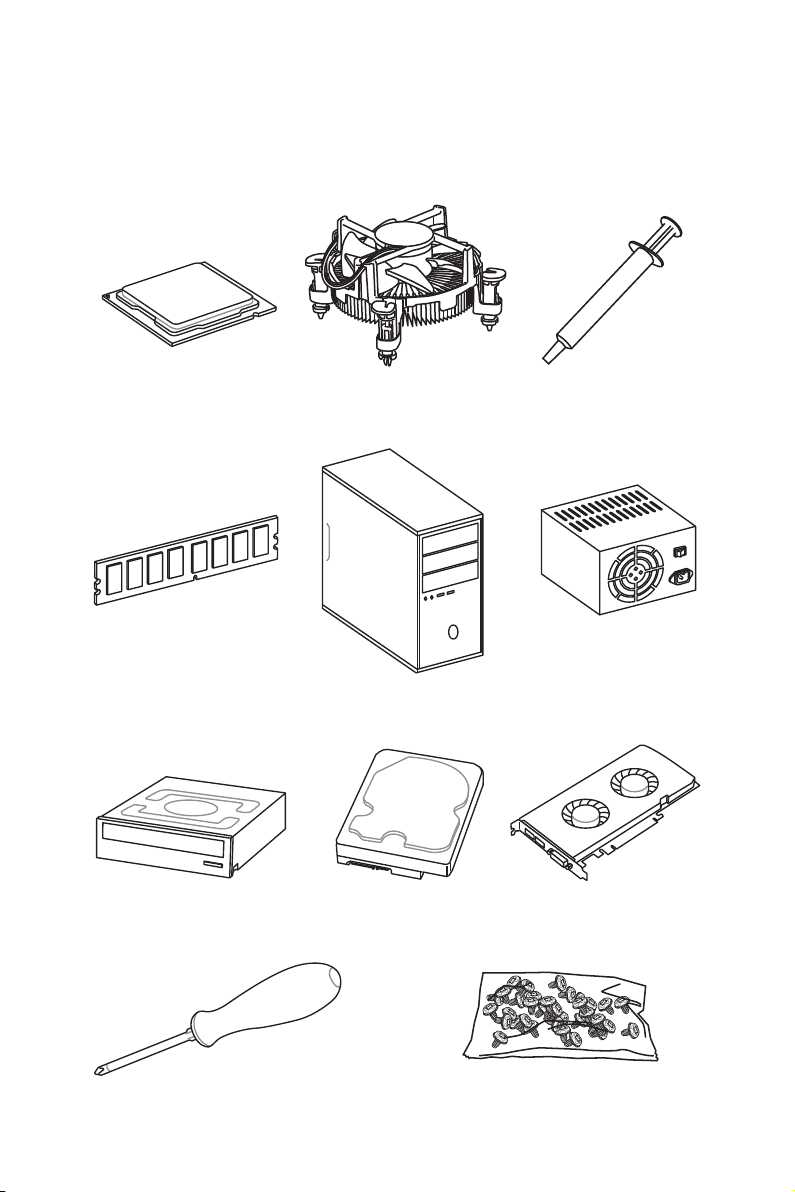
Quick Start
Preparing Tools and Components
Intel® LGA 1151 CPU
DDR4 Memory
SATA DVD Drive
CPU Fan Thermal Paste
Chassis
SATA Hard Disk Drive
Power Supply Unit
Graphics Card
Phillips Screwdriver
A Package of Screws
Quick Start
3
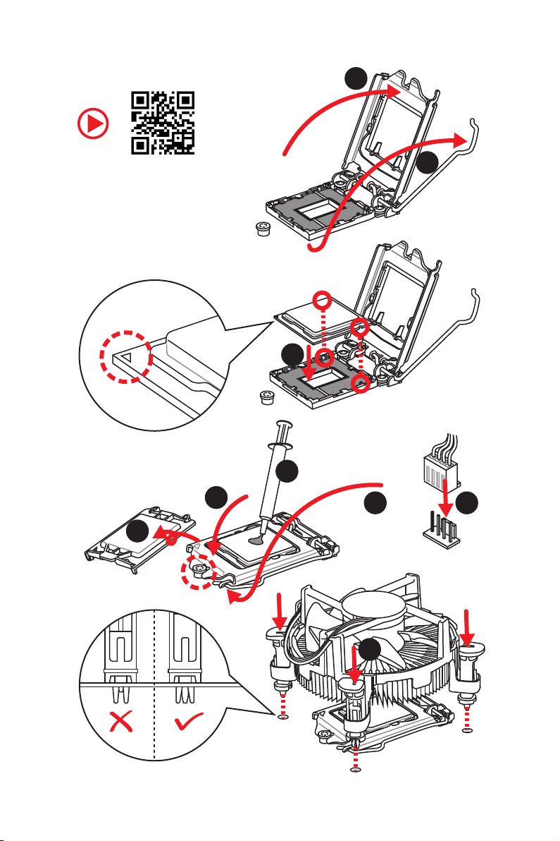
Installing a Processor
2
http://youtu.be/bf5La099urI
6
1
3
7
4
5
9
Quick Start
4
8
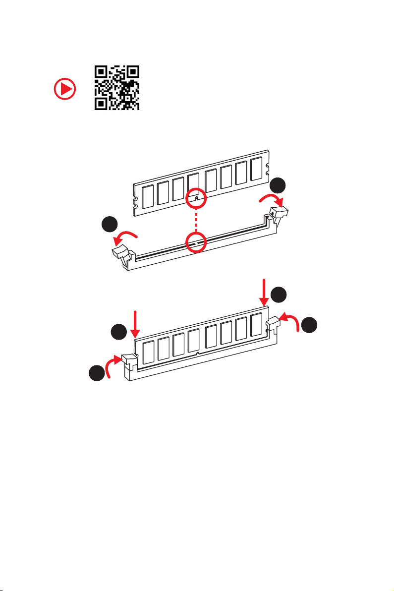
Installing DDR4 memory
http://youtu.be/T03aDrJPyQs
1
1
2
2
3
3
Quick Start
5
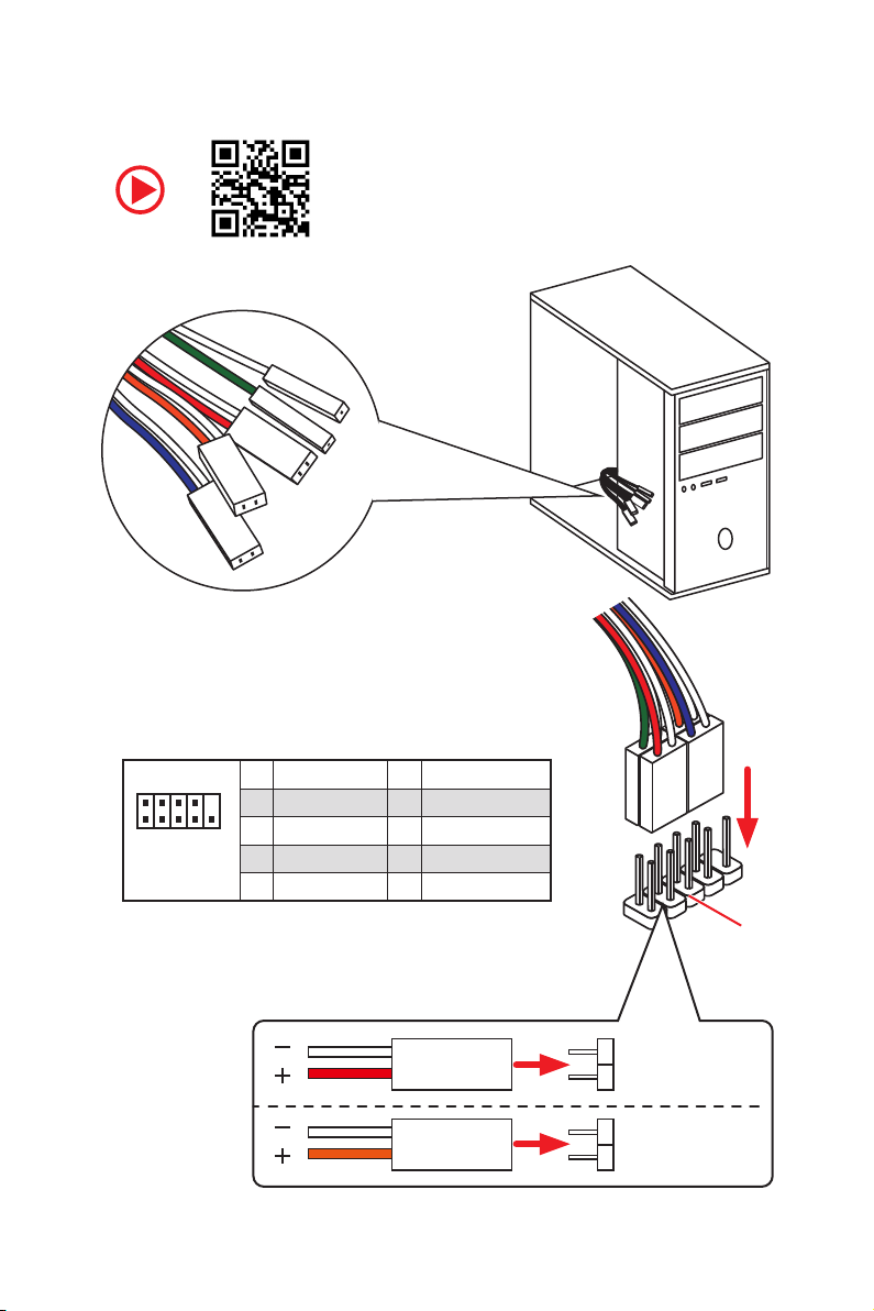
Connecting the Front Panel Header
RESET SW
POWER SW
POWER LED+
POWER LED-
HDD LED
http://youtu.be/DPELIdVNZUI
Quick Start
6
2 10
1
JFP1
1 HDD LED + 2 Power LED +
3 HDD LED - 4 Power LED -
5 Reset Switch 6 Power Switch
9
7 Reset Switch 8 Power Switch
9 Reserved 10 No Pin
HDD LED
POWER LED
RESET SW
HDD LED
JFP1
HDD LED HDD LED +
POWER LED POWER LED +
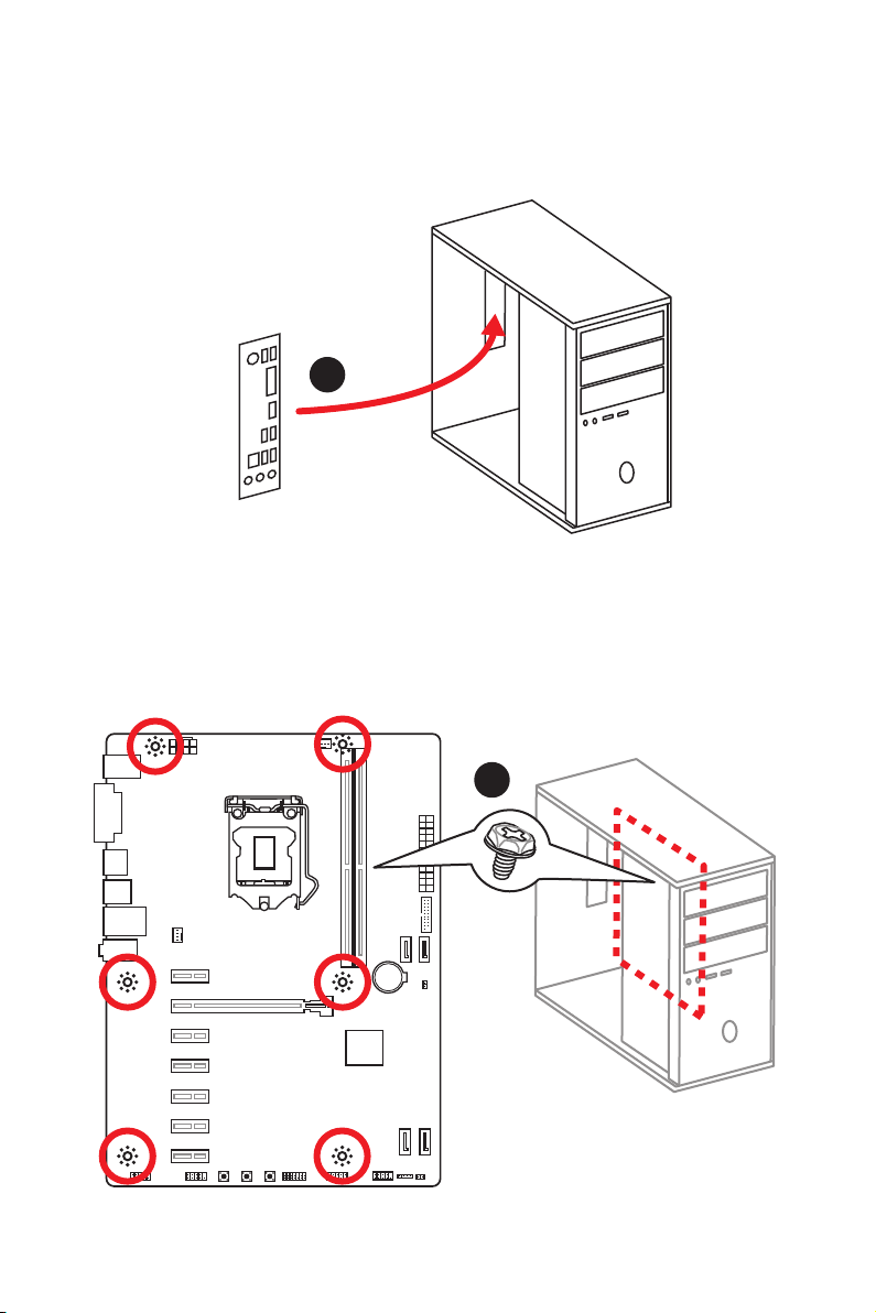
Installing the Motherboard
1
2
BAT1
Quick Start
7

Installing SATA Drives
http://youtu.be/RZsMpqxythc
2
1
3
Quick Start
8
5
4
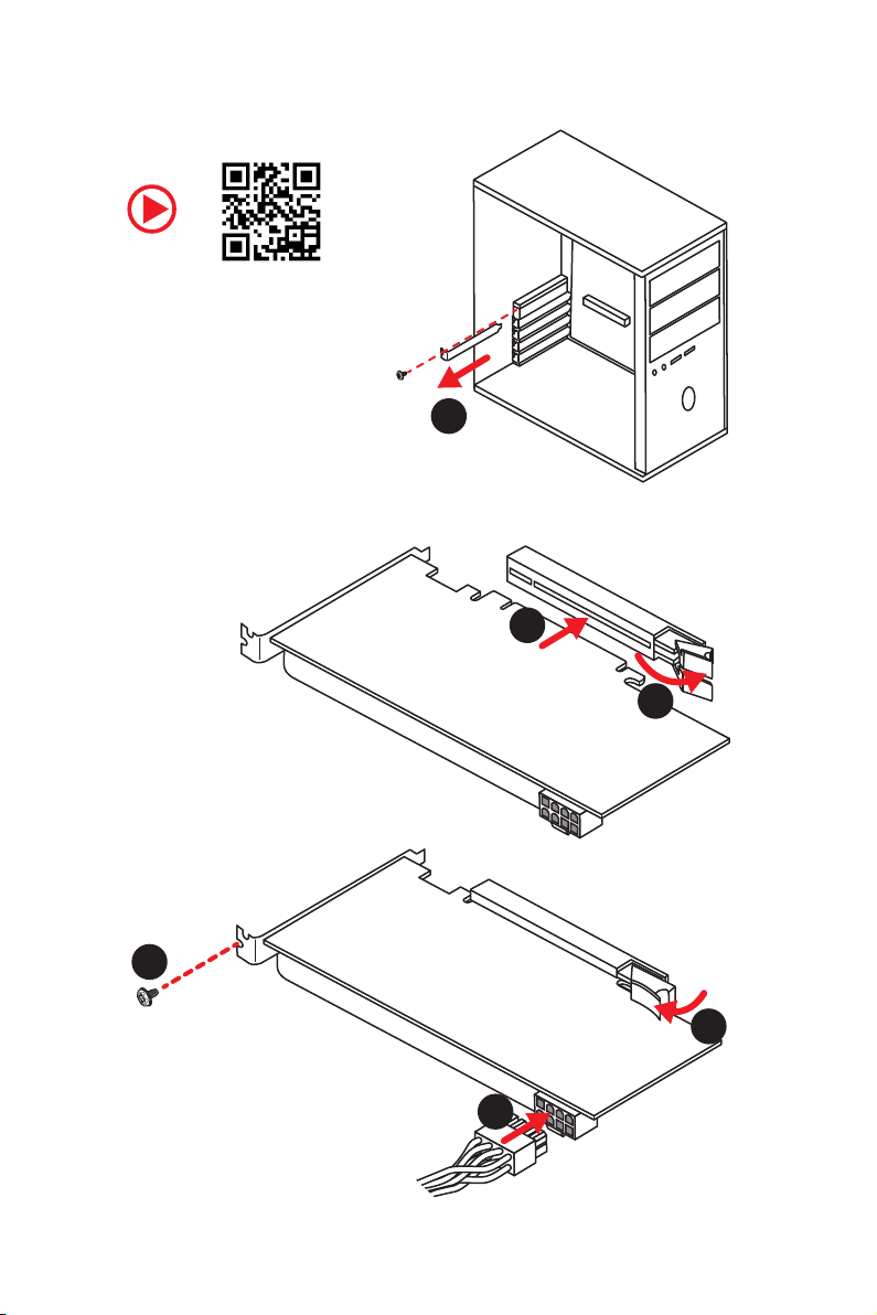
Installing a Graphics Card
http://youtu.be/mG0GZpr9w_A
1
3
2
5
4
6
Quick Start
9
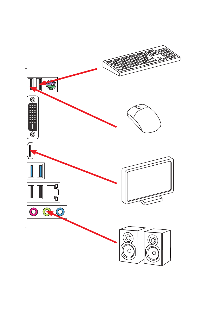
Connecting Peripheral Devices
10
Quick Start

Connecting the Power Connectors
http://youtu.be/gkDYyR_83I4
ATX_PWR1
CPU_PWR1
Quick Start
11
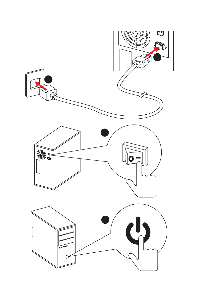
Power On
1
2
3
12
4
Quick Start

Contents
Unpacking .............................................................................................................. 1
Safety Information ................................................................................................. 2
Quick Start ............................................................................................................. 3
Preparing Tools and Components .......................................................................... 3
Installing a Processor ............................................................................................. 4
Installing DDR4 memory ........................................................................................ 5
Connecting the Front Panel Header ....................................................................... 6
Installing the Motherboard ..................................................................................... 7
Installing SATA Drives.............................................................................................8
Installing a Graphics Card ...................................................................................... 9
Connecting Peripheral Devices ............................................................................ 10
Connecting the Power Connectors ....................................................................... 11
Power On............................................................................................................... 12
Specifications ....................................................................................................... 15
Block Diagram .................................................................................................... 19
Rear I/O Panel ..................................................................................................... 20
LAN Port LED Status Table................................................................................... 20
Realtek HD Audio Manager .................................................................................. 21
Overview of Components .................................................................................... 22
CPU Socket ........................................................................................................... 24
DIMM Slots ............................................................................................................ 25
PCI_E1~7: PCIe Expansion Slots .......................................................................... 26
SATA1~4: SATA 6Gb/s Connectors ....................................................................... 26
CPU_PWR1, ATX_PWR1: Power Connectors ....................................................... 27
JFP1, JFP2: Front Panel Connectors ................................................................... 28
JUSB2: USB 3.1 Gen1 Connector ......................................................................... 28
JUSB1: USB 2.0 Connector .................................................................................. 29
JCOM1: Serial Port Connector ............................................................................. 29
CPU_FAN1,SYS_FAN1: Fan Connectors ............................................................... 30
JAUD1: Front Audio Connector ............................................................................31
JCI1: Chassis Intrusion Connector ....................................................................... 31
JTPM1: TPM Module Connector ........................................................................... 32
RESET1: Reset Button .......................................................................................... 32
POWER1: Power Button........................................................................................ 32
CLR_CMOS1: Clear CMOS Button ........................................................................ 32
JBAT1: Clear CMOS (Reset BIOS) Jumper ........................................................... 33
EZ Debug LED ....................................................................................................... 33
Contents
13

BIOS Setup ........................................................................................................... 34
Entering BIOS Setup ............................................................................................. 34
Resetting BIOS ...................................................................................................... 35
Updating BIOS ....................................................................................................... 35
EZ Mode ................................................................................................................ 36
Advanced Mode .................................................................................................... 38
SETTINGS .............................................................................................................. 39
Advanced ............................................................................................................... 39
Boot ....................................................................................................................... 45
Security ................................................................................................................. 46
Save & Exit ............................................................................................................ 47
OC .......................................................................................................................... 48
M-FLASH .............................................................................................................. 54
OC PROFILE .......................................................................................................... 55
HARDWARE MONITOR .......................................................................................... 56
Software Description ........................................................................................... 57
Installing Windows® 10 ......................................................................................... 57
Installing Drivers .................................................................................................. 57
Installing Utilities ................................................................................................. 57
APP MANAGER ..................................................................................................... 58
LIVE UPDATE 6 ...................................................................................................... 59
COMMAND CENTER ............................................................................................. 61
X-BOOST ............................................................................................................... 65
SMART TOOL ......................................................................................................... 67
RAMDISK............................................................................................................... 69
NETWORK MANAGER ........................................................................................... 70
Troubleshooting .................................................................................................. 72
Regulatory Notices .............................................................................................. 73
14
Contents
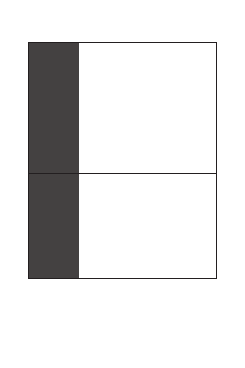
Specifications
CPU
Chipset Intel
Memory
Celeron
*Please refer to www.msi.com for more information on compatible memory.
®
y Supports 8th Gen Intel
®
processors for Socket LGA1151
®
H310 Chipset
Core™, Pentium® Gold and
y 2x DDR4 memory slots, support up to 32GB
y Supports DDR4 2666/ 2400/ 2133 MHz*
y Dual channel memory architecture
y Supports non-ECC UDIMM memory
y Supports Intel
®
Extreme Memory Profile (XMP)
Expansion Slots
y 1x PCIe 3.0 x16 slot
y 6x PCIe 2.0 x1 slots
y 1x HDMI™ port 1.4, supports a maximum resolution of
Onboard Graphics
4096x2160@30Hz
y 1x DVI-D port, supports a maximum resolution of
1920x1200 @ 60Hz
®
Storage
Intel
y 4x SATA 6Gb/s ports*
y Intel
4x USB 3.1 Gen1 (SuperSpeed USB) ports (2 ports on
the back panel, 2 ports available through the internal
USB
USB connector)
6x USB 2.0 (High-speed USB) ports (4 Type-A ports on
the back panel, 2 ports available through the internal
USB connector)
Audio
y Realtek
y 7.1-Channel High Definition Audio
LAN 1x Intel
H310 Chipset
®
H310 Chipset
®
ALC887 Codec
®
I219-V Gigabit LAN controller
Continued on next page
Specifications
15

Back Panel
Connectors
Internal Connectors
Continued from previous page
y 1x PS/2 keyboard/ mouse combo port
y 4x USB 2.0 Type-A ports
y 1x DVI-D port
y 1x HDMI™ port
y 2x USB 3.1 Gen1 Type-A ports
y 1x LAN (RJ45) port
y 3x audio jacks
y 1x 24-pin ATX main power connector
y 1x 8-pin ATX 12V power connector
y 4x SATA 6Gb/s connectors
y 1x USB 3.1 Gen1 connector (supports additional 2 USB 3.1
Gen1 ports)
y 1x USB 2.0 connector (supports additional 2 USB 2.0 ports)
y 1x 4-pin CPU fan connector
y 1x 4-pin system fan connectors
y 1x Front panel audio connector
y 2x Front panel connectors
y 1x Series port connector
y 1x TPM module connector
y 1x Chassis Intrusion connector
y 1x Clear CMOS jumper
y 1x Power button
y 1x Reset button
y 1x Clear CMOS button
I/O Controller NUVOTON NCT5567 Controller Chip
y CPU/System temperature detection
Hardware Monitor
From Factor
Specifications
16
y CPU/System fan speed detection
y CPU/System fan speed control
y ATX Form Factor
y 12 in. x 8.9 in. (30.5 cm x 22.5 cm)
Continued on next page

BIOS Features
Software
Continued from previous page
y 1x 128 Mb flash
y UEFI AMI BIOS
y ACPI 6.1, SM BIOS 2.8
y Multi-language
y Drivers
y APP MANAGER
y SUPER CHARGER
y COMMAND CENTER
y LIVE UPDATE 6
y SMART TOOL
y RAMDISK
y FAST BOOT
y X-BOOST
y DPC LATENCY TUNER
y NETWORK MANAGER
y CPU-Z MSI GAMING
®
y Intel
Extreme Tuning Utility
y Google Chrome™ ,Google Toolbar, Google Drive
y Norton™ Internet Security Solution
Continued on next page
Specifications
17

Special Features
Continued from previous page
y Audio
Audio Boost
y Network
®
Intel
LAN with Network Manager
y Fan
Smart Fan Control
y LED
EZ DEBUG LED
y Stability
7000+ Quality Test
y VR
VR Ready
y BIOS
Click BIOS 5
18
Specifications
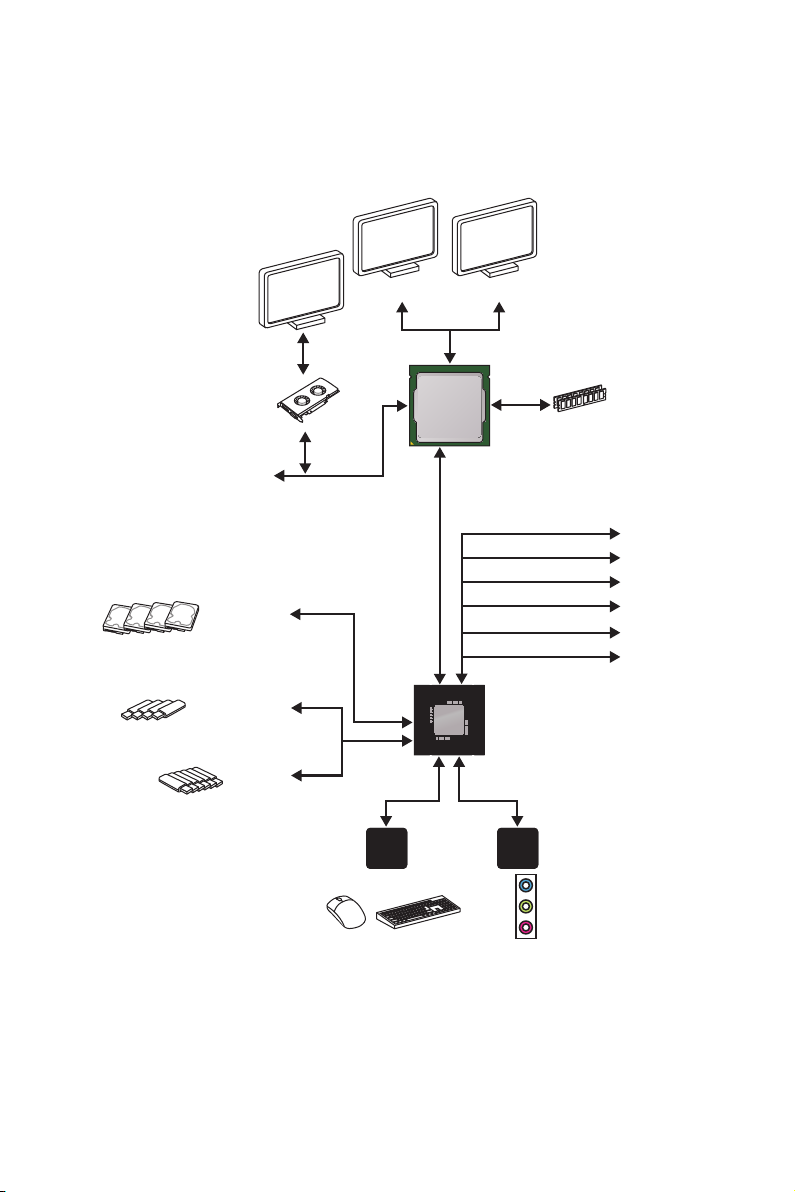
Block Diagram
HDMI DVI-D
2 Channel DDR4 Memory
CPU
4 x SATA 6Gb/s
4 x USB 3.1 Gen1
6 x USB 2.0
PCI Express Bus
P/S2 Mouse / Keyboard
NV5567
Super I/O
LPC Bus
DMI 3.0
chipset
Realtek
ALC887
Audio Jacks
x1
x1
x1
x1
x1
x1
PCIe x1 slot
PCIe x1 slot
PCIe x1 slot
PCIe x1 slot
PCIe x1 slot
PCIe x1 slot
Block Diagram
19
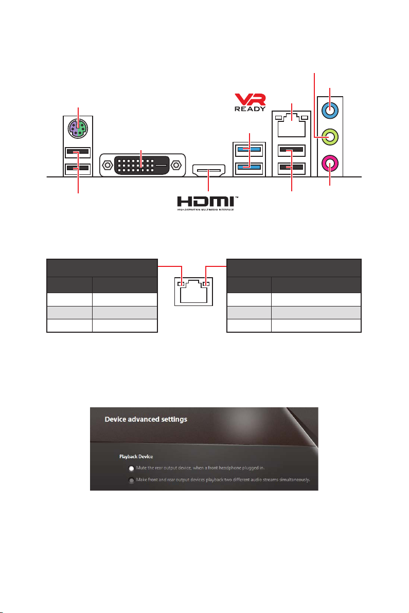
Rear I/O Panel
PS/2
DVI-D
Line-out
Line-in
LAN
USB 3.1
Gen1
USB 2.0
USB 2.0
LAN Port LED Status Table
Mic-in
Link/ Activity LED
Status Description
Off No link
Yellow Linked
Blinking Data activity
Audio 7.1-channel Configuration
To configure 7.1-channel audio, you have to connect front audio I/O module to JAUD1
connector and follow the below steps.
1. Click on the Realtek HD Audio Manager > Advanced Settings to open the dialog
below.
Speed LED
Status Description
Off 10 Mbps connection
Green 100 Mbps connection
Orange 1 Gbps connection
2. Select Mute the rear output device, when a front headphone plugged in.
3. Plug your speakers to audio jacks on rear and front I/O panel. When you plug into
a device at an audio jack, a dialogue window will pop up asking you which device is
current connected.
Rear I/O Panel
20
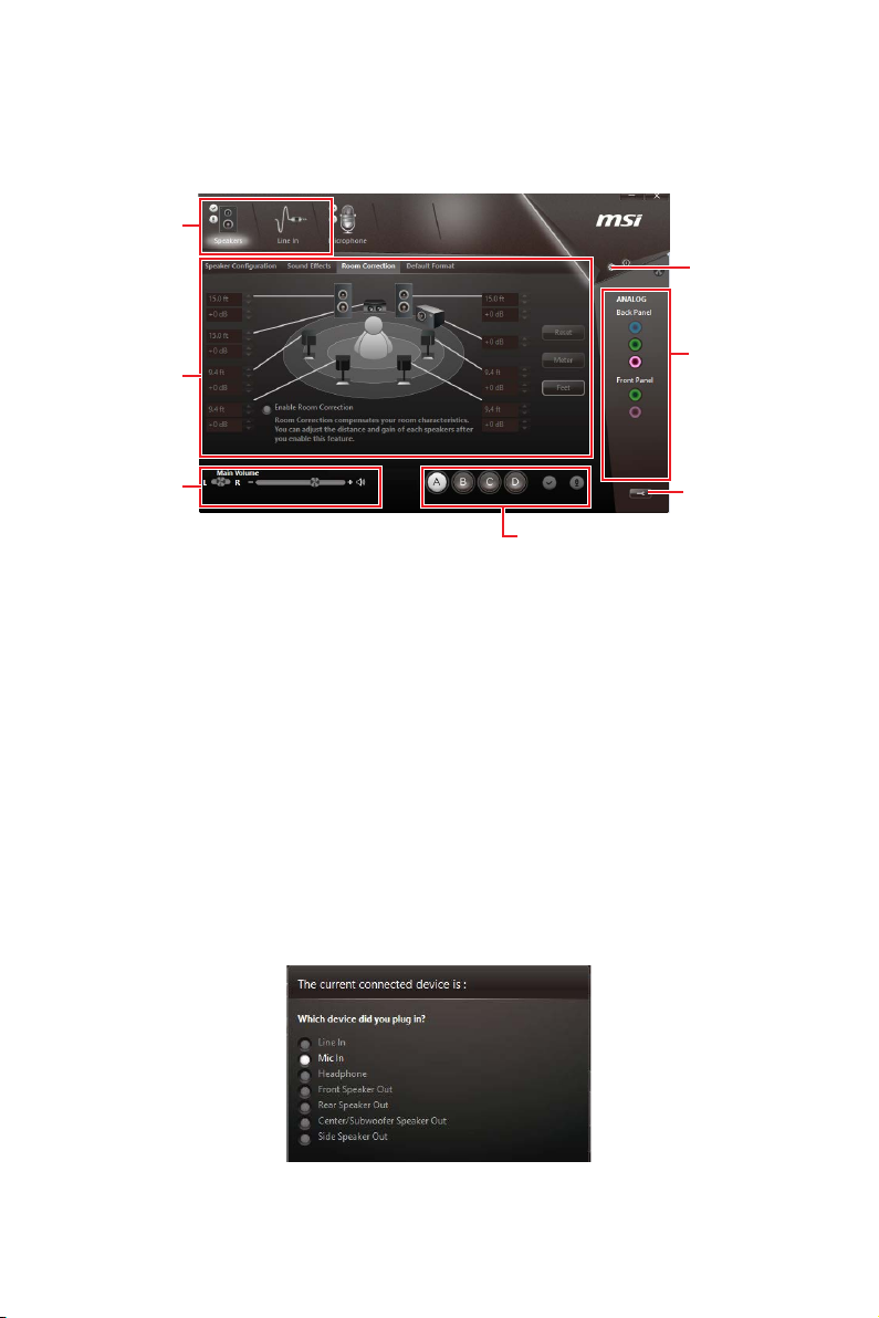
Realtek HD Audio Manager
After installing the Realtek HD Audio driver, the Realtek HD Audio Manager icon will
appear in the system tray. Double click on the icon to launch.
Device
Selection
Advanced
Settings
Application
Enhancement
Main Volume
Profiles
Jack Status
Connector
Strings
y Device Selection - allows you to select a audio output source to change the related
options. The check sign indicates the devices as default.
y Application Enhancement - the array of options will provide you a complete guidance
of anticipated sound effect for both output and input device.
y Main Volume - controls the volume or balance the right/left side of the speakers that
you plugged in front or rear panel by adjust the bar.
y Profiles - toggles between profiles.
y Advanced Settings - provides the mechanism to deal with 2 independent audio
streams.
y Jack Status - depicts all render and capture devices currently connected with your
computer.
y Connector Settings - configures the connection settings.
Auto popup dialog
When you plug into a device at an audio jack, a dialogue window will pop up asking you
which device is current connected.
Each jack corresponds to its default setting as shown on the next page.
Rear I/O Panel
21
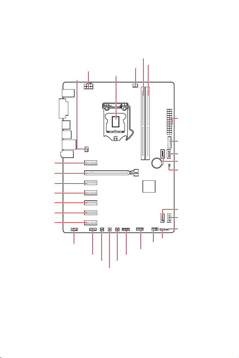
Overview of Components
CPU_PWR1
SYS_FAN1
PCI_E2
PCI_E1
PCI_E3
PCI_E4
PCI_E5
PCI_E6
PCI_E7
CPU_FAN1
CPU Socket
DIMMA1
DIMMB1
ATX_PWR1
JUSB2
SATA1
BAT1
SATA2
JBAT1
SATA4
SATA3
JCI1
Overview of Components
22
JAUD1
JCOM1
RESET1
CLR_CMOS1
POWER1
JTPM1
JUSB1
JFP1
JFP2
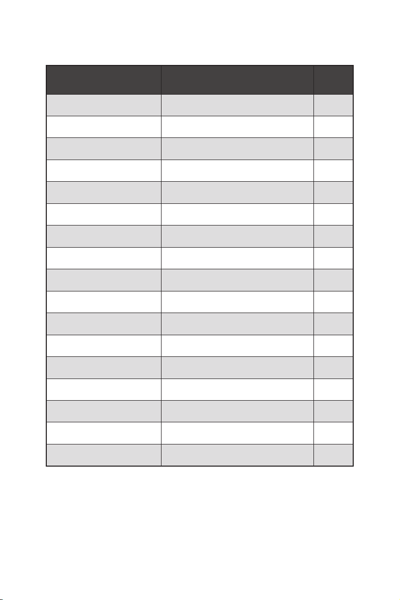
Component Contents
Port Name Port Type Page
CLR_CMOS1 Clear CMOS Button 32
CPU_FAN1,SYS_FAN1 Fan Connectors 30
CPU_PWR1, ATX_PWR1 Power Connectors 27
CPU Socket LGA1151 CPU Socket 24
DIMMA1/ B1 DIMM Slots 25
JAUD1 Front Audio Connector 31
JBAT1 Clear CMOS Jumper 33
JCI1 Chassis Intrusion Connector 31
JCOM1 Serial Port Connector 29
JFP1, JFP2 Front Panel Connectors 28
JTPM1 TPM Module Connector 32
JUSB1 USB 2.0 Connector 29
JUSB2 USB 3.1 Gen1 Connector 28
PCI_E1~7 PCIe Expansion Slots 26
POWER1 Power Button 32
RESET1 Reset Button 32
SATA1~4 SATA 6Gb/s Connectors 26
Overview of Components
23
 Loading...