

Page 1
E7230 Master Series
MS-9618 (v1.X) ATX Server Board
English Version
G52-S9618X1
i
Page 2

Copyright Notice
The material in this document is the intellectual property of MICRO-STAR
INTERNATIONAL. We take every care in the preparation of this document, but no
guarantee is given as to the correctness of its contents. Our products are under
continual improvement and we reserve the right to make changes without notice.
Trademarks
All trademarks are the properties of their respective owners.
Intel® and Pentium® are registered trademarks of Intel Corporation.
AMD, Athlon™ , Athlon™ XP, Thoroughbred™, and Duron™ are registered trademarks of AMD Corporation.
PS/2 and OS®/2 are registered trademarks of International Business Machines
Corporation.
Windows® 95/98/2000/NT/XP are registered trademarks of Microsoft Corporation.
Netware® is a registered trademark of Novell, Inc.
Award® is a registered trademark of Phoenix Technologies Ltd.
AMI® is a registered trademark of American Megatrends Inc.
Revision History
Revision Revision History Date
V1.0 First release September 2005
Technical Support
If a problem arises with your system and no solution can be obtained from the user’s
manual, please contact your place of purchase or local distributor. Alternatively,
please try the following help resources for further guidance.
Visit the MSI website for FAQ, technical guide, BIOS updates, driver updates,
and other information: http://www.msi.com.tw/program/service/faq/
faq/esc_faq_list.php
Contact our technical staff at: support@msi.com.tw
ii
Page 3
Safety Instructions
1. Always read the safety instructions carefully.
2. Keep this User’s Manual for future reference.
3. Keep this equipment away from humidity.
4. Lay this equipment on a reliable flat surface before setting it up.
5. The openings on the enclosure are for air convection hence protects the equipment from overheating. DO NOT COVER THE OPENINGS.
6. Make sure the voltage of the power source and adjust properly 110/220V before connecting the equipment to the power inlet.
7. Place the power cord such a way that people can not step on it. Do not place
anything over the power cord.
8. Always Unplug the Power Cord before inserting any add-on card or module.
9. All cautions and warnings on the equipment should be noted.
10. Never pour any liquid into the opening that could damage or cause electrical
shock.
11. If any of the following situations arises, get the equipment checked by a service
personnel:
† The power cord or plug is damaged.
† Liquid has penetrated into the equipment.
† The equipment has been exposed to moisture.
† The equipment has not work well or you can not get it work according to
User’s Manual.
† The equipment has dropped and damaged.
† The equipment has obvious sign of breakage.
12. DO NOT leave this mainboard in an unconditioned environment with storage
temperature above 70oC (158oF) or operating temperature above 35oC (95oF); it
may damage the mainboard.
CAUTION: Danger of explosion if battery is incorrectly replaced.
Replace only with the same or equivalent type recommended by the
manufacturer.
iii
Page 4
FCC-B Radio Frequency Interference Statement
This equipment has been
tested and found to comply
with the limits for a Class B
digital device, pursuant to Part
15 of the FCC Rules. These limits are designed to provide reasonable protection
against harmful interference in a residential installation. This equipment generates,
uses and can radiate radio frequency energy and, if not installed and used in accordance with the instructions, may cause harmful interference to radio communications.
However, there is no guarantee that interference will not occur in a particular
installation. If this equipment does cause harmful interference to radio or television
reception, which can be determined by turning the equipment off and on, the user is
encouraged to try to correct the interference by one or more of the measures listed
below.
† Reorient or relocate the receiving antenna.
† Increase the separation between the equipment and receiver.
† Connect the equipment into an outlet on a circuit different from that to
which the receiver is connected.
† Consult the dealer or an experienced radio/television technician for help.
Notice 1
The changes or modifications not expressly approved by the party responsible for
compliance could void the user’s authority to operate the equipment.
Notice 2
Shielded interface cables and A.C. power cord, if any, must be used in order to
comply with the emission limits.
VOIR LA NOTICE D’ INSTALLATION AVANT DE RACCORDER AU RESEAU.
Micro-Star International
MS-9618
This device complies with Part 15 of the FCC Rules. Operation is subject to the
following two conditions:
(1) this device may not cause harmful interference, and
(2) this device must accept any interference received, including interference that
may cause undesired operation.
iv
Page 5

WEEE (Waste Electrical and Electronic Equipment) Statement
v
Page 6
vi
Page 7
vii
Page 8

CONTENTS
Copyright Notice..............................................................................................................ii
Trademarks.......................................................................................................................ii
Revision History..............................................................................................................ii
Technical Support...........................................................................................................ii
Safety Instructions..........................................................................................................iii
FCC-B Radio Frequency Interference Statement........................................................iv
WEEE (Waste Electrical and Electronic Equipment) Statement....................................v
Chapter 1. Getting Started....................................................................................1-1
Mainboard Specifications...................................................................................1-2
Mainboard Layout................................................................................................1-4
MSI Special Features..........................................................................................1-5
PC Alert™ III..................................................................................................1-5
Chapter 2. Hardware Setup..................................................................................2-1
Quick Components Guide....................................................................................2-2
Central Processing Unit: CPU.............................................................................2-3
Introduction to LGA 775 CPU......................................................................2-3
CPU & Cooler Installation.............................................................................2-4
Memory.................................................................................................................2-7
Introduction to DDR2 SDRAM......................................................................2-7
Memory Module Population Rules...............................................................2-7
Installing DDR2 Modules..............................................................................2-8
Power Supply......................................................................................................2-9
ATX 20-Pin System Power Connector: ATX1............................................2-9
ATX 4-Pin CPU Power Connector: JPW1...................................................2-9
Back Panel..........................................................................................................2-10
Mouse Connector (Green) / Keyboard Connector (Purple)..................2-10
Serial Port....................................................................................................2-11
VGA Port......................................................................................................2-11
USB Ports...................................................................................................2-12
LAN (RJ-45) Jacks.....................................................................................2-12
Parallel Port Connector: LPT1...................................................................2-13
Connectors........................................................................................................2-14
Floppy Disk Drive Connector: FDD1..........................................................2-14
Hard Disk Connector: IDE1........................................................................2-14
Serial ATA Connectors: SATA1~SATA4...................................................2-15
Chassis Intrusion Switch Connector: JCI1..............................................2-16
viii
Page 9

Front Panel Connector: JFP1....................................................................2-16
Power Saving Switch Connector: JGS1.................................................2-17
LAN LED Connectors: JACT1, JACT2......................................................2-17
Fan Power Connectors: CPU_FAN1, SFAN1/2/3/4.................................2-17
LCD Panel Connector: JLCD1...................................................................2-18
Serial Port Header: COM2.........................................................................2-18
Front USB Connectors: JUSB1, JUSB2..................................................2-19
Jumpers..............................................................................................................2-20
Clear CMOS Jumper: JBAT1.....................................................................2-20
BIOS Write Protect Jumper: J2.................................................................2-21
LAN Disable/Enable Jumpers: J5, J8........................................................2-21
Slots....................................................................................................................2-22
PCI (Peripheral Component Interconnect) Express Slots.......................2-22
PCI (Peripheral Component Interconnect) Slots......................................2-22
PCI Interrupt Request Routing...................................................................2-23
Chapter 3. BIOS Setup............................................................................................3-1
Entering Setup.....................................................................................................3-2
Getting Help..................................................................................................3-2
General Help <F1>.......................................................................................3-2
The Menu Bar.......................................................................................................3-3
Main......................................................................................................................3-4
Advanced............................................................................................................3-7
Security..............................................................................................................3-18
Power.................................................................................................................3-19
Boot....................................................................................................................3-20
Exit......................................................................................................................3-21
Appendix A: Intel ICH7R SATA RAID (Optional).................................................A-1
BIOS Configuration..............................................................................................A-2
Using the Intel Matrix Stroage Manager Option ROM to Create, Delete, and
Reset RAID Volumes....................................................................................A-2
Installing Software..............................................................................................A-8
Install Driver in Windows 2000 / 2003.......................................................A-8
Installation of Intel Matrix Stroage Console...............................................A-9
RAID Migration Instructions...............................................................................A-14
Create RAID Volume from Existing Disk...................................................A-15
ix
Page 10

Getting Started
Chapter 1. Getting
Started
Getting Started
Thank you for choosing the E7230 Master Series (MS-9618 v1.X),
an excellent ATX server board from MSI.
Based on the innovative Intel® E7230 & Intel® ICH7R chipsets for
optimal system efficiency, the E7230 Master Series mainboard accommodates the latest Intel® Pentium® 4 / Pentium® D processors
in LGA775 package and supports up to four 240-pin 533/667MHz
unbuffered ECC DDR-II DIMMs to provide the maximum of 8GB memory
capacity.
In the entry-level and mid-range market segment, this mainboard can
provide a high-performance solution for today’s front-end and general purpose server/workstation, as well as in the future.
1-1
Page 11

MS-9618 ATX Server Board
Mainboard Specifications
CPU
† Supports Intel® Pentium® 4 / Pentium® D processors in LGA775 package
† Supports Intel® Hyper-Threading Technology
(For more information on compatible components, please visit http://www.msi.
com.tw/program/products/server/svr/pro_svr_qvl.php)
Chipset
† Intel® E7230 Northbridge
- Supports Intel® Pentium® 4 / Pentium® D processors Front Side Bus (FSB) at
533/800/1066 MT/s
- PCI Express external graphics support
- Supports DDR-II 533/667 memory interface
† Intel® ICH7R Southbridge
- Hi-Speed USB (USB2.0) controller, 480Mb/sec
- 4 SATAII ports with transfer rate up to 3Gb/s
- 1 channel Ultra ATA 100 bus Master IDE controller
- PCI Master v2.3, I/O APIC
- ACPI 2.0 Compliant
- Serial ATA RAID 0, RAID 1, and Matrix RAID
- Integrated AHCI controller
Main Memory
† Supports four unbuffered ECC DIMMs of 1.8 Volt DDR-II SDRAM
† Supports up to 8GB memory size
† Supports Dual-Channel DDR-II 533/667 memory interface
(For more information on compatible components, please visit http://www.msi
com.tw/program/products/server/svr/pro_svr_qvl.php)
Slots
† Three 32-bit/33MHz v2.3 PCI slots (support 3.3V/5V PCI bus interface)
† One PCI Express x8 slot (this PCIE_2 slot will accept x8 cards, but run at x4
speeds / PCI Express Bus specification v1.0a compliant)
† One PCI Express x8 slot (this PCIE_1 slot will accept x8 cards and run at x8
speeds / PCI Express Bus specification v1.0a compliant)
HDD Interface
† Ultra DMA 66/100 IDE controller integrated in ICH7R
- Supports PIO, Bus Master operation modes
- Can connect up to two Ultra ATA drives
† SATAII controller integrated in ICH7R
- Up to 300MB/sec data transfer rate
- Can connect up to four SATA devices
- Supports AHCI controller with SATA RAID 0, SATA RAID 1, SATA RAID 5, SATA
RAID 10 and Matrix RAID (ICH7R)
.
1-2
Page 12

Getting Started
Onboard Peripherals
† 1 floppy port supports one FDD with 360KB, 720KB, 1.2MB, 1.44MB, and 2.88MB
† 1 PS/2 keyboard port
† 1 PS/2 mouse port
† 1 serial port & 1 serial pinheader
† 1 VGA port
† 1 parallel port supports SPP/EPP/ECP mode
† 2 RJ-45 ports (with LEDs)
† 6 USB ports (4 on the front and 2 on the rear)
Onboard Graphics
† ATI Radeon 7000 Graphics Controller
- Onboard 16MB Video SDRAM
- Uses PCI 32-bit/33MHz interface on ICH7R
Onboard LAN
† Intel 82573V/L Gigabit Ethernet Controller
- Uses PCI Express x1 interface on ICH7R
- Supports 10Mb/s, 100Mb/s, and 1000Mb/s
Power Management Features
† Wake up on LAN (WOL), wake up on serial ring, wake up on PCI
† RTC alarm and wake up
† Wake up on keyboard/mouse/USB from S1
† Supports ACPI S1, S4, S5 function
System Management
† SMBus (I2C)
† Temperature, voltage, and fan monitors
† Chassis intrusion
Operating Environment
† Operating Temperature Range: +10oC ~ +35oC (+50oF ~ +95oF)
† Non-Operating Temperature Range: -40oC ~ +70oC (-104oF ~ +158oF)
BIOS
† The mainboard BIOS provides “Plug & Play” BIOS which detects the peripheral
devices and expansion cards of the board automatically
† The mainboard provides a Desktop Management Interface (DMI) function which
records your mainboard specifications
Mounting and Dimension
† ATX Form Factor: 30.5cm (L) x 24.4cm (W)
† 9 mounting holes
1-3
Page 13

MS-9618 ATX Server Board
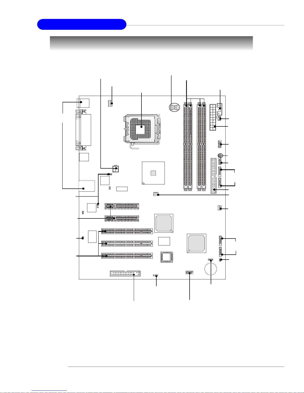
PCI 2
PCIE_2
PCIE_1
BATT+BIOS
JUSB1
JBAT1
SFAN3
CPU_FAN1
IDE 1
Top: Mouse
Bottom: Keyboard
Top:
Parallel Port
Bottom:
COM A
VGA Port
USB
Ports
JPWR1
J5
PC82573V
LAN Jacks
PC82573V
N217230C1
J7
N217230C1
J6
J8
Mainboard Layout
S FAN 2
S FAN 1
INTEL
E7230
SFAN4
ATI
PCI 3
RADEON
C O M 2
JLCD 1
ATX1
J U S B 2
JACT1
JACT2
JFP1
S ATA4
S ATA3
DIMM1
DIMM3
DIMM2
DIMM4
1-4
JGS1
INTEL
ICH7R
PCI 1
JCI1
FDD 1
J2
E7230 Master Series (MS-9618 v1.X) ATX Server Board
S ATA2
S ATA1
Page 14

Getting Started
MSI Special Features
PC Alert™ III
The PC AlertTM III is a utility you can find in the application CD. The utility is just like your
PC doctor that can detect the following PC hardware status during real time operation:
ö monitor CPU & system temperatures
ö monitor fan speed(s)
ö monitor system voltage
ö monitor chassis intrusion
If one of the items above is abnormal, the program
main screen will be immediately shown on the
screen, with the abnormal item highlighted in red.
This will continue to be shown until user disables
the warning.
MSI Reminds You...
Items shown on PC Alert™ III vary depending on your system status.
1-5
Page 15

Hardware Setup
Chapter 2. Hardware
Setup
Hardware Setup
This chapter provides you with the information about hardware setup
procedures. While doing the installation, be careful in holding the
components and follow the installation procedures. For some
components, if you install in the wrong orientation, the components
will not work properly.
Use a grounded wrist strap before handling computer components.
Static electricity may damage the components.
2-1
Page 16
MS-9618 ATX Server Board
Quick Components Guide
I/O Ports,
p.2-10
J5/J8, p.2-21
PCI Express
Slots, p.2-22
JPW1, p.2-9
CPU_FAN1, p.2-17
CPU, p.2-3
SFAN2/1,
p.2-17
DIMM1/2/3/4, p.2-7
COM2, p.2-18
JLCD1, p.2-18
ATX1, p.2-9
JUSB2, p.2-19
JACT1/2,
p.2-17
JFP1, p.2-16
SATA4/
SATA3, p.2-15
IDE1, p.2-14
SFAN4, p.2-17
SFAN3, p.2-17
JGS1, p.2-17
PCI Slots,
p.2-22
2-2
FDD1, p.2-14
J2, p.2-21
SATA2/
SATA1, p.2-15
JCI1, p.2-16
JBAT1, p.2-20
JUSB1, p.2-19
Page 17
Hardware Setup
Central Processing Unit: CPU
The mainboard supports Intel® Pentium® 4 / Pentium® D processors in 775-pin
package. The mainboard uses a CPU socket called LGA775 for easy CPU installation.
When you are installing the CPU, make sure the CPU has a heat sink and a
cooling fan attached on the top to prevent overheating. If you do not have the
heat sink and cooling fan, contact your dealer to purchase and install them before
turning on the computer.
For more information on compatible components, please visit http://www.msi.com.
tw/program/products/server/svr/pro_svr_qvl.php .
MSI Reminds You...
Overheating
Overheating will seriously damage the CPU and system, always make
sure the cooling fan can work properly to protect the CPU from
overheating.
Replacing the CPU
While replacing the CPU, always turn off the ATX power supply or
unplug the power supply’s power cord from grounded outlet first to
ensure the safety of CPU.
Overclocking
This motherboard is designed to support overclocking. However, please
make sure your components are able to tolerate such extreme settings while doing overclocking. Any attempt to operate beyond product
specifications is not recommended. We do not guarantee the dam-
ages or risks caused by inadequate operation or beyond product specifications.
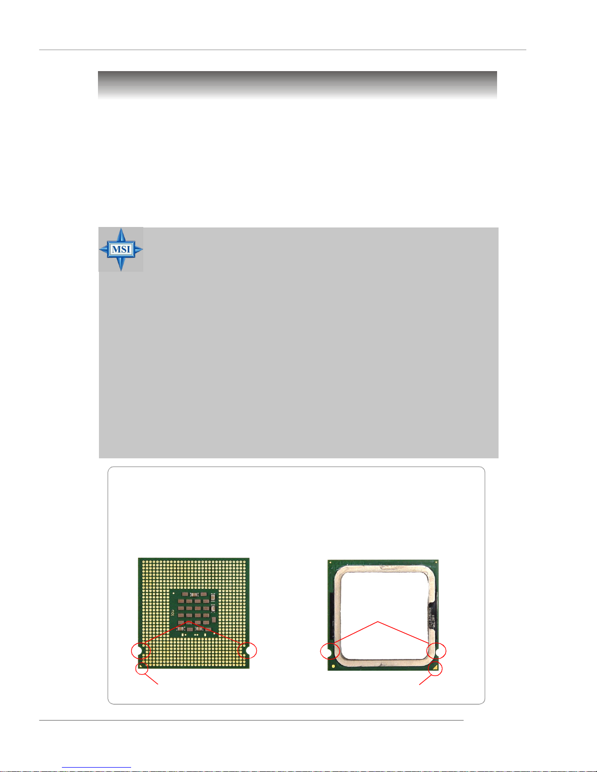
Introduction to LGA 775 CPU
The pin-pad side of LGA 775
CPU.
Alignment Key Alignment Key
The surface of LGA 775 CPU.
Remember to apply some
silicone heat transfer compound
on it for better heat dispersion.
Yellow triangle is the Pin 1 indicator
Yellow triangle is the Pin 1 indicator
2-3
Page 18
MS-9618 ATX Server Board
CPU & Cooler Installation
When you are installing the CPU, make sure the CPU has a cooler attached on
the top to prevent overheating. If you do not have the cooler, contact your dealer
to purchase and install them before turning on the computer. Meanwhile, do not forget
to apply some silicon heat transfer compound on CPU before installing the heat sink/
cooler fan for better heat dispersion.
Follow the steps below to install the CPU & cooler correctly. Wrong installation will
cause the damage of your CPU & mainboard.
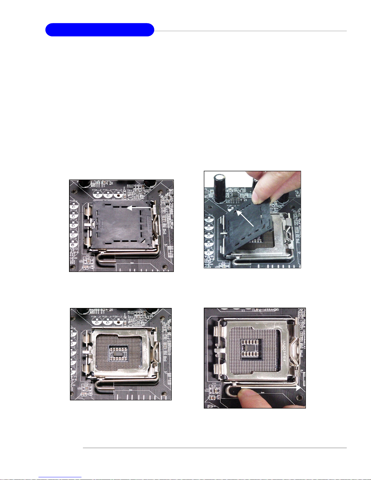
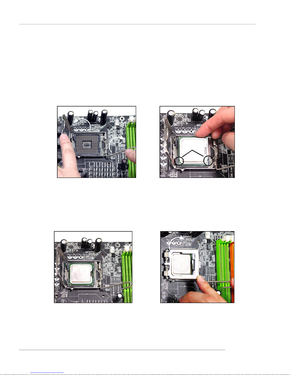
1.The CPU has a plastic cap on it to
protect the contact from damage.
Before you install the CPU,
always cover it to protect the
socket pin.
3.The pins of socket reveal.
2.Remove the cap from lever hinge
side (as the arrow shows).
4.Open the load lever.
2-4
Page 19
Hardware Setup
5.Lift the load lever up and open the
load plate.
6.After confirming the CPU
direction for correct mating, put
down the CPU in the socket
housing frame. Be sure to grasp
on the edge of the CPU base.
Note that the alignment keys are
matched.
alignment
key
7.Visually inspect if the CPU is
seated well into the socket. If
not, take out the CPU with pure
vertical motion and reinstall.
8.Cover the load plate onto the
package.
2-5
Page 20
MS-9618 ATX Server Board
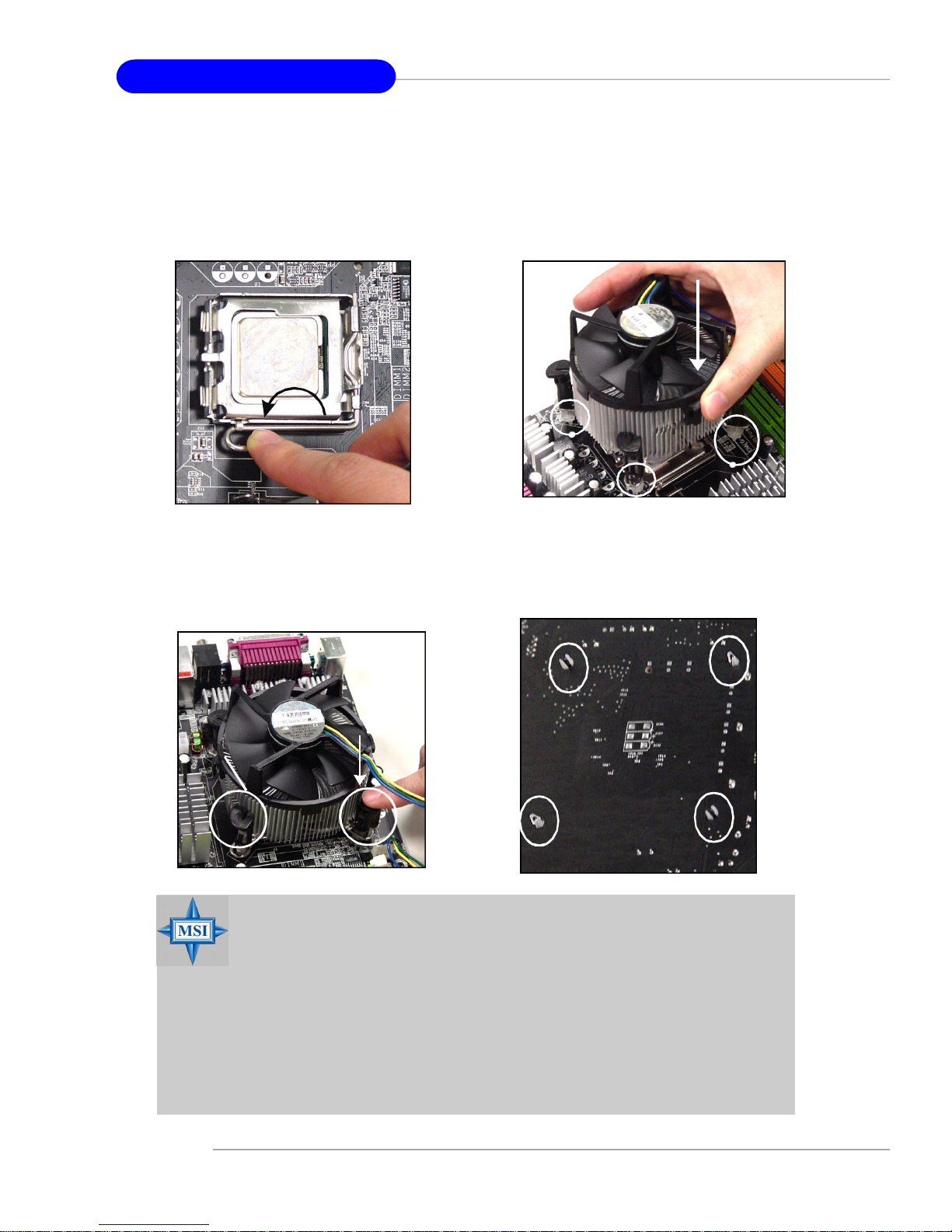
9.Press down the load lever lightly
onto the load plate, and then
secure the lever with the hook
under retention tab.
11.Press the four hooks down to
fasten the cooler. Then rotate the
locking switch (refer to the
correct direction marked on it) to
lock the hooks.
10. Align the holes on the mainboard
with the heatsink. Push down the
cooler until its four clips get
wedged into the holes of the
mainboard.
12.Turn over the mainboard to
confirm that the clip-ends are
correctly inserted.
2-6
locking
switch
MSI Reminds You...
1.Confirm if your CPU cooler is firmly installed before turning on your
system.
2.Check the information in PC Health Status of H/W Monitor in BIOS
(refer to p.3-21 for details) for the CPU temperature.
3.Do not touch the CPU socket pins to avoid damage.
4. Whenever CPU is not installed, always protect your CPU socket pin
with the plastic cap covered (shown in Figure 1) to avoid damage.
5. Please note that the mating/unmating durability of the CPU is 20 cycles.
Therefore we suggest you do not plug/unplug the CPU too often.
Page 21
Hardware Setup
Memory
The mainboard supports up to four 240-pin 533/667MHz unbuffered ECC DDR-II
DIMMs to provide the maximum of 4GB memory capacity.
Since DDR2 modules are not interchangeable with DDR and the DDR2 standard is not
backwards compatible, you should always install DDR2 memory module in the DDR2
slot (DIMM1~DIMM4). Otherwise, you will not be able to boot up your system and your
mainboard might be damaged.
For more information on compatible components, please visit http://www.msi.com.
tw/program/products/server/svr/pro_svr_qvl.php .
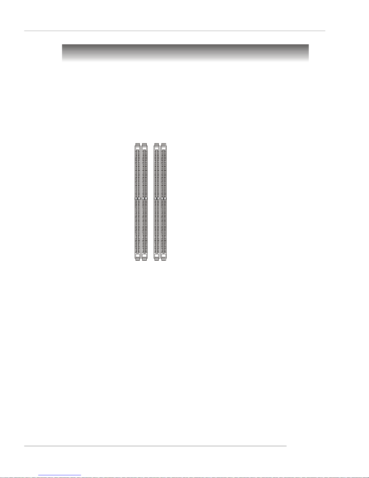
DIMM1~DIMM4
(from left to right)
Channel A (DIMM1, DIMM2)
Channel B (DIMM3, DIMM4)
Introduction to DDR2 SDRAM
DDR2 is a new technology of memory module, and its speed is the top limit of current
DDR technology. DDR2 uses a 1.8V supply for core and I/O voltage, compared to 2.
5V for DDR, and requires 28% less power than DDR chips. DDR2 truly is the future of
memory, but will require some changes as the technology is not backwardly compatible and only motherboards specifically designed for DDR2 memory will be able to
support these chips.
DDR2 incorporates new features at the chip level that give it better signal integrity,
thereby enabling higher clock speeds.
DDR2 modules have 240 pins, versus 184 pins on a DDR module, and the length of
DDR2 module is 5.25”. DDR2 modules have smaller and tighter spaced pins. The
height of DDR2 modules varies, but they will typically be less than 1.3” in height.
Memory Module Population Rules
Install at least one DIMM module on the slots. Each DIMM slot supports up to a maximum
size of 1GB. Users can install either single- or double-sided modules to meet their
own needs. Please note that each DIMM can work respectively for single-
channel DDR2, while both channels populated with the same amount of
memory size will work as dual-channel DDR2.
2-7
Page 22
MS-9618 ATX Server Board
DIMM1 (Ch A) DIMM2 (Ch A) DIMM3 (Ch B) DIMM4 (Ch B) System Density
256MB~1GB 256MB~1GB 512MB~2GB
256MB~1GB 256MB~1GB 512MB~2GB
256MB~1GB 256MB~1GB 512MB~2GB
256MB~1GB 256MB~1GB 512MB~2GB
256MB~1GB 256MB~1GB 256MB~1GB 256MB~1GB 1GB~4GB
MSI Reminds You...
-Dual-channel DDR2 works ONLY in the 5 combinations listed in
the table shown in the previous page.
-Please select the identical memory modules to install on the dual
channel, and DO NOT install three memory modules on three
DIMMs, or it may cause some failure.
-Always insert the memory modules into the Channel A slots first.
-Due to the South Bridge resource deployment, the system density
will only be detected up to 3+GB (not full 4GB) when each DIMM is
installed with an 1GB memory module.
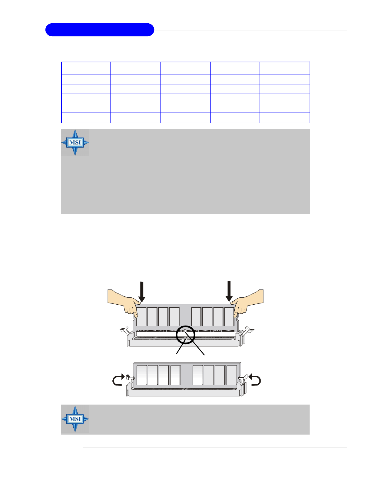
Installing DDR2 Modules
1. The DDR2 DIMM has only one notch on the center of module. The module will
only fit in the right orientation.
2. Insert the DIMM memory module vertically into the DIMM slot. Then push it in
until the golden finger on the memory module is deeply inserted in the socket.
3. The plastic clip at each side of the DIMM slot will automatically close.
Volt
Notch
MSI Reminds You...
You can barely see the golden finger if the module is properly inserted
in the socket.
2-8
Page 23
Hardware Setup
Power Supply
The mainboard supports ATX power supply for the power system. Before inserting
the power supply connector, always make sure that all components are installed
properly to ensure that no damage will be caused.
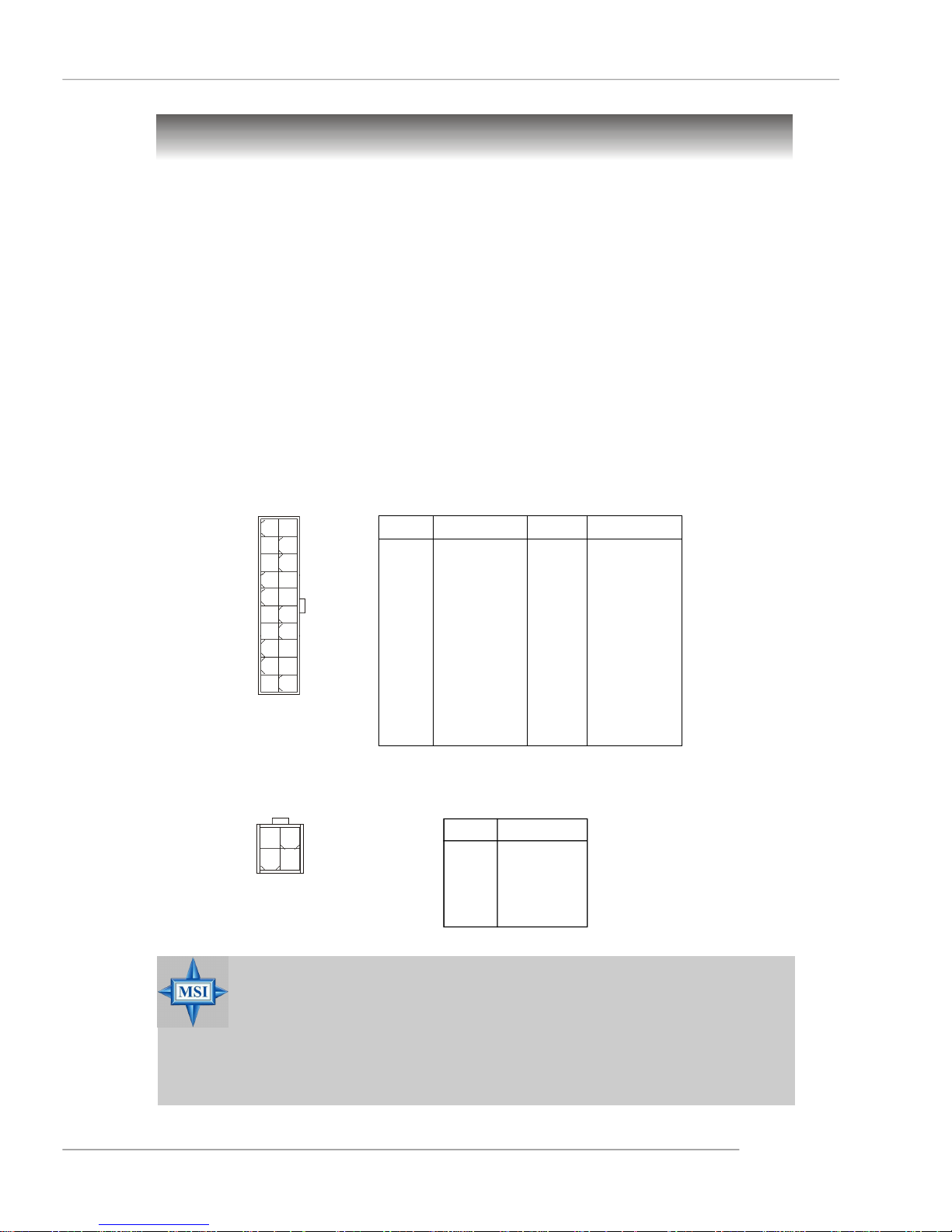
ATX 20-Pin System Power Connector: ATX1
This connector allows you to connect to an ATX power supply. To connect to the ATX
power supply, make sure the plug of the power supply is inserted in the proper
orientation and the pins are aligned. Then push down the power supply firmly into the
connector.
ATX 4-Pin CPU Power Connector: JPW1
This connector provides 12V power output to the CPU.
ATX1 Pin Definition
10
1
ATX1
3 4
1
JPW1
20
11
PIN SIGNAL
1 3.3V
2 3.3V
3 GND
4 5V
5 GND
6 5V
7 GND
8 PW_OK
9 5V_SB
10 12V
PIN SIGNAL
11 3.3V
12 -12V
13 GND
14 PS_ON
15 GND
16 GND
17 GND
18 -5V
19 5V
20 5V
JPW1 Pin Definition
PIN SIGNAL
2
1 GND
2 GND
3 12V
4 12V
MSI Reminds You...
1. Maker sure that these two connectors are connected to adequate
ATX power supplies to ensure stable operation of the mainboard.
2. Power supply of 350watts (and above) is highly recommended for
system stability.
3. ATX 12V power connection should be greater than 18A.
2-9
Page 24
MS-9618 ATX Server Board
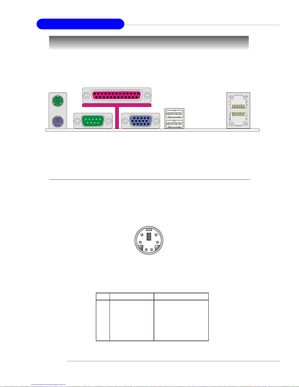
Back Panel
Parallel
Mouse
Keyboard COM Port USB Ports
VGA Port
LAN1
LAN2
Mouse Connector (Green) / Keyboard Connector (Purple)
The mainboard provides a standard PS/2® mouse/keyboard mini DIN connector for
attaching a PS/2® mouse/keyboard. You can plug a PS/2® mouse/keyboard directly
into this connector. The connector location and pin assignments are as follows:
2-10
6
4
2
5
3
1
PS/2 Mouse / Keyboard
(6-pin Female)
Pin Definition
PIN SIGNAL DESCRIPTION
1 Mouse/Keyboard Data Mouse/Keyboard data
2 NC No connection
3 GND Ground
4 VCC +5V
5 Mouse/Keyboard Clock Mouse/Keyboard clock
6 NC No connection
Page 25

Hardware Setup
Serial Port
The mainboard offers one 9-pin male DIN connector as the serial port. The port is a
16550A high speed communication port that sends/receives 16 bytes FIFOs. You can
attach a serial mouse or other serial devices directly to the connector.
Pin Definition
1 2 3 4 5
6 7 8 9
9-Pin Male DIN Connector
PIN SIGNAL DESCRIPTION
1 DCD Data Carry Detect
2 SIN Serial In or Receive Data
3 SOUT Serial Out or Transmit Data
4 DTR Data Terminal Ready
5 GND Ground
6 DSR Data Set Ready
7 RTS Request To Send
8 CTS Clear To Send
9 RI Ring Indicate
VGA Port
The mainboard provides a DB 15-pin female connector to connect a VGA monitor.
5
15
VGA Connector
Pin Signal Description Pin Signal Description
1 RED 2 GREEN
3 BLUE 4 N/C
5 GND 6 GND
7 GND 8 GND
9 +5V 10 GND
11 N/C 12 SDA
13 Horizontal Sync 14 Vertical Sync
15 SCL
1
11
2-11
Page 26

MS-9618 ATX Server Board
USB Ports
The rear panel provides two UHCI (Universal Host Controller Interface) Universal
Serial Bus roots for attaching USB devices such as keyboard, mouse or other USBcompatible devices. You can plug the USB device directly into the connector.
1 2 3 4
USB Port
USB Port Description
PIN SIGNAL DESCRIPTION
1 VCC +5V
2 -Data 0 Negative Data Channel 0
3 +Data0 Positive Data Channel 0
4 GND Ground
LAN (RJ-45) Jacks
The mainboard provides 2 standard RJ-45 jacks for connection to single Local Area
Network (LAN). This Giga-bit LAN enables data to be transferred at 1000, 100 or
10Mbps. You can connect a network cable to either LAN jack.
8 1
RJ-45 LAN Jack
Giga-bit LAN Pin Definition
PIN SIGNAL DESCRIPTION
1 D0P Differential Pair 0+
2 D0N Differential Pair 03 D1P Differential Pair 1+
4 D2P Differential Pair 2+
5 D2N Differential Pair 26 D1N Differential Pair 17 D3P Differential Pair 3+
8 D3N Differential Pair 3-
2-12
Page 27

Hardware Setup
Parallel Port Connector: LPT1
The mainboard provides a 25-pin female centronic connector as LPT. A parallel port is
a standard printer port that supports Enhanced Parallel Port (EPP) and Extended
Capabilities Parallel Port (ECP) mode.
13 1
25
14
Pin Definition
PIN SIGNAL DESCRIPTION
1 STROBE Strobe
2 DATA0 Data0
3 DATA1 Data1
4 DATA2 Data2
5 DATA3 Data3
6 DATA4 Data4
7 DATA5 Data5
8 DATA6 Data6
9 DATA7 Data7
10 ACK# Acknowledge
11 BUSY Busy
12 PE Paper End
13 SELECT Select
14 AUTO FEED# Automatic Feed
15 ERR# Error
16 INIT# Initialize Printer
17 SLIN# Select In
18 GND Ground
19 GND Ground
20 GND Ground
21 GND Ground
22 GND Ground
23 GND Ground
24 GND Ground
25 GND Ground
2-13
Page 28

MS-9618 ATX Server Board
Connectors
The mainboard provides connectors to connect to FDD, IDE HDD, case, LAN, USB
Ports, CPU/system power supply fans, ... and etc.
Floppy Disk Drive Connector: FDD1
The mainboard provides a standard floppy disk drive connector that supports 360K,
720K, 1.2M, 1.44M and 2.88M floppy disk types.
FDD1
Hard Disk Connector: IDE1
The mainboard provides a one-channel Ultra ATA 100 bus Master IDE controller that
supports PIO mode 0 ~ 4, Bus Master, and Ultra DMA 33/66/100 function. You can
connect up to two hard disk drives, CD-ROM drives, 120MB floppy disk drive (reserved
for future BIOS), and other devices.
IDE1
IDE1 Definition
IDE VDMA Controller RAID ATAPI
1 66/100 Intel ICH6 N/A Yes
IDE1 (Primary IDE Connector)
IDE1 can connect a Master and a Slave drive. You must configure the second
hard drive to Slave mode by setting the jumper accordingly.
MSI Reminds You...
If you install two hard disks on cable, you must configure the second
drive to Slave mode by setting its jumper. Refer to the hard disk documentation supplied by hard disk vendors for jumper setting instructions.
2-14
Page 29

Hardware Setup
Serial ATA Connectors: SATA1~SATA4
The ICH7R south bridge supports four serial ATA connectors SATA1~SATA4.
SATA1~SATA4 are high-speed Serial ATA interface ports. Each supports serial ATA
data rates of 300MB/s and is fully compliant with Serial ATA 2.0 specifications. Each
Serial ATA connector can connect to 1 hard disk device. Please refer to Appendix B
for detailed software installation & operation.
SATA1~4
7
1
PIN SIGNAL PIN SIGNAL
1 GND 2 TXP
3 TXN 4 GND
5 RXN 6 RXP
7 GND
Serial ATA Cable (Optional)
SATA1/2/3/4 Pin Definition
Take out the dust cover
and connect to the hard
disk devices
Connect to serial ATA ports
MSI Reminds You...
Please do not fold the Serial ATA cable into 90-degree angle. Otherwise,
the loss of data may occur during transmission.
2-15
Page 30

MS-9618 ATX Server Board
Chassis Intrusion Switch Connector: JCI1
This connector is connected to a 2-pin chassis switch. If the chassis is opened, the
switch will be short. The system will record this status and show a warning message on the screen. To clear the warning, you must enter the BIOS utility and clear the
record.
GND
CINTRU
2
1
JCI1
Front Panel Connector: JFP1
The mainboard provides one front panel connector for electrical connection to the
front panel switches and LEDs. The JFP1 is compliant with Intel® Front Panel I/O
Connectivity Design Guide.
JFP1
910
Power
Switch
Power
LED
2
1
Reset
Switch
HDD
LED
PIN SIGNAL DESCRIPTION
1 HD_LED_P Hard disk LED pull-up
2 FP PWR/SLP MSG LED pull-up
3 HD_LED_N Hard disk active LED
4 FP PWR/SLP MSG LED pull-up
5 RST_SW_N Reset Switch low reference pull-down to GND
6 PWR_SW_P Power Switch high reference pull-up
7 RST_SW_P Reset Switch high reference pull-up
8 PWR_SW_N Power Switch low reference pull-down to GND
9 RSVD_DNU Reserved. Do not use.
2-16
JFP1 Pin Definition
Page 31

Hardware Setup
Power Saving Switch Connector: JGS1
Attach a power saving switch to this connector. Press the switch once to have the
system entered the Sleep/Suspend state. Press any key to wake up the system.
JGS1
LAN LED Connectors: JACT1, JACT2
The LAN LED connectors are used to connect to LAN LEDs, which show the activity
of the LAN. JACT1 is for LAN2 jack and the JACT2 is for LAN1 jack. Both LAN1 &
LAN2 jacks are located on the back panel.
JACT1
-
+
-
+
JACT2
Fan Power Connectors: CPU_FAN1, SFAN1/2/3/4
The fan power connectors support system cooling fan with +12V. When connecting
the wire to the connectors, always note that the red wire is the positive and should
be connected to the +12V; the black wire is Ground and should be connected to GND.
If the mainboard has a System Hardware Monitor chipset onboard, you must use a
specially designed fan with speed sensor to take advantage of the CPU fan control.
GND
+12V
SENSOR
Control
CPU_FAN1
SFAN1/2
MSI Reminds You...
1. Please refer to the recommended CPU fans at Intel® official website
or consult the vendors for proper CPU cooling fan.
2. CPU_FAN1 supports Smart Fan control. You can install PC Alarm
utility that will automatically control the CPU fan speed according to
the actual CPU temperature. Alternatively, you may set up the smart
fan control functions in the BIOS setup utility.
GND
+12V
SENSOR
SENSOR
+12V
GND
SFAN3
Sensor
GND
+12V
SFAN4
2-17
Page 32

MS-9618 ATX Server Board
LCD Panel Connector: JLCD1
The connector is additionally provided for connection to a LCD panel, which shows
information on the panel for you to identify the current status or mode of the connected system.
JLCD1
1
5 6
2
PIN SIGNAL
1 TX
2 RX
3 NC
4 GND1
5 GND0
6 VCC
Serial Port Header: COM2
The mainboard offers one 9-pin header as serial port. The port is a 16550A high
speed communication port that sends/receives 16 bytes FIFOs. You can attach a
serial mouse or other serial device directly to it.
1
2
2-18
9
COM 2
Pin Definition
PIN SIGNAL DESCRIPTION
1 DCD Data Carry Detect
2 SIN Serial In or Receive Data
3 SOUT Serial Out or Transmit Data
4 DTR Data Terminal Ready
5 GND Ground
6 DSR Data Set Ready
7 RTS Request To Send
8 CTS Clear To Send
9 RI Ring Indicate
Page 33

Hardware Setup
Front USB Connectors: JUSB1, JUSB2
The mainboard provides two standard USB 2.0 pinheaders. USB 2.0 technology
increases data transfer rate up to a maximum throughput of 480Mbps, which is 40
times faster than USB 1.1, and is ideal for connecting high-speed USB interface
peripherals such as USB HDD, digital cameras, MP3 players, printers, modems
and the like.
10 9
JUSB1
2
1
PIN SIGNAL PIN SIGNAL
1 VCC 2 VCC
3 USB0- 4 USB15 USB0+ 6 USB1+
7 GND 8 GND
9 Key (no pin) 10 USBOC
10
9
Pin Definition
1 2
JUSB2
Connect to JUSB1 or JUSB2
(the USB pinheader in YELLOW color)
MSI Reminds You...
Note that the pins of VCC and GND must be connected correctly to
avoid possible damage.
USB 2.0 Bracket
(Optional)
2-19
Page 34

MS-9618 ATX Server Board
Jumpers
The motherboard provides the following jumpers for you to set the computer’s function.
This section will explain how to change your motherboard’s function through the use
of jumpers.
Clear CMOS Jumper: JBAT1
There is a CMOS RAM on board that has a power supply from external battery to keep
the data of system configuration. With the CMOS RAM, the system can automatically
boot OS every time it is turned on. If you want to clear the system configuration, use
the JBAT1 (Clear CMOS Jumper ) to clear data. Follow the instructions below to clear
the data:
JBAT1
1
1 3
Keep Data
1 3
Clear Data
MSI Reminds You...
You can clear CMOS by shorting 2-3 pin while the system is off. Then
return to 1-2 pin position. Avoid clearing the CMOS while the system is
on; it will damage the mainboard.
2-20
Page 35

Hardware Setup
BIOS Write Protect Jumper: J2
A "boot block" program is included as part of the system BIOS to recover the system
from a situation when the BIOS code is incorrect/corrupted or needs to be updated.
When the BIOS code is corrupted or needs to be updated, you have to at first disable
the write protect function by shorting 1-2 pin of the J2 jumper. Then the boot block will
try to recover the BIOS code, usually by reading it from a specially-prepared floppy
disk.
Under normal operation, we suggest that you enable the write protect function by
shorting 2-3 pin of the J2 jumper to protect the boot block from virus infection.
1
J2
13
3
Disable Write Protect
1
3
Enable Write Protect
LAN Disable/Enable Jumpers: J5, J8
The J5 jumper is used to enable/disable the onboard LAN1 controller while the J8 is
used to control the onboard LAN2 controller.
J5
3
1
Enable LAN1
1
3
Disable LAN1
1
1
J8
1
3
Enable LAN2
1
3
Disable LAN2
2-21
Page 36

MS-9618 ATX Server Board
The mainboard provides:
† Three 32-bit/33MHz v2.3 PCI slots (support 3.3V/5V PCI bus interface)
† One PCI Express x8 slot (this PCIE_2 slot will accept x8 cards, but run
at x4 speeds / PCI Express Bus specification v1.0a compliant)
† One PCI Express x8 slot (this PCIE_1 slot will accept x8 cards and run at
x8 speeds / PCI Express Bus specification v1.0a compliant)
Slots
PCI (Peripheral Component Interconnect) Express Slots
The PCI Express slots support high-bandwidth, low pin count, and serial interconnect
technology. PCI Express connectors are similar in appearance and connection method
to 32-bit PCI slots. PCI Express 1X slots are about the size of current modem riser
slots (about 1" long), while the X16 interface (164 pins) for graphics is very similar in
appearance to the standard AGP port. The flexibility to adapt to PCI express devices
of different bandwidths is built into the midrange X4 and X8 slots that we have seen.
PCI Express architecture provides a high performance I/O infrastructure for Desktop
Platforms with transfer rates starting at 2.5 Giga transfers per second over a PCI
Express x1 lane for Gigabit Ethernet, TV Tuners, 1394 controllers, and general purpose I/O. Also, desktop platforms with PCI Express Architecture will be designed to
deliver highest performance in video, graphics, multimedia and other sophisticated
applications. Moreover, PCI Express architecture provides a high performance graphics
infrastructure for Desktop Platforms doubling the capability of existing AGP 8x designs with transfer rates of 4.0 GB/s over a PCI Express x16 lane for graphics
controllers, while PCI Express x1 supports transfer rate of 250 MB/s.
PCI (Peripheral Component Interconnect) Slots
The PCI slots allow you to insert the expansion cards to meet your needs. When
adding or removing expansion cards, make sure that you unplug the power supply
first. Meanwhile, read the documentation for the expansion card to make any necessary hardware or software settings for the expansion card, such as jumpers,
switches or BIOS configuration.
2-22
Page 37

Hardware Setup
PCI Interrupt Request Routing
The IRQ, acronym of interrupt request line and pronounced I-R-Q, are hardware lines
over which devices can send interrupt signals to the microprocessor. The PCI IRQ
pins are typically connected to the PCI bus pins as follows:
DEVICE ICH INT Pin IDSEL CLOCK REQ / GNT
PCI Slot 1 INT# F/G/H/E AD21 CK_PCI 0 REQ#1/ GNT#1
PCI Slot 2 INT# G/H/E/F AD22 CK_PCI 1 REQ#2/ GNT#2
PCI Slot 3 INT# H/E/F/G AD23 CK_PCI 2 REQ#3/ GNT#3
VGA INT# A AD16 CK_VGA REQ#0/ GNT#0
2-23
Page 38

BIOS Setup
Chapter 3. BIOS Setup
BIOS Setup
This chapter provides information on the BIOS Setup program and
allows you to configure the system for optimum use. You may need
to run the Setup program when:
² An error message appears on the screen during the system boot-
ing up, and requests you to run SETUP.
² You want to change the default settings for customized features.
MSI Reminds You...
1. The items under each BIOS category described in this chapter
are under continuous update for better system performance.
Therefore, the description may be slightly different from the latest BIOS and should be held for reference only.
2. Upon boot-up, the 1st line appearing after the memory count is
the BIOS version. It is usually in the format:
P9618IMS V1.0 081505 where:
1st digit refers to BIOS maker as A = AMI, W = AWARD,
and P = PHOENIX.
2nd - 5th digit refers to the model number.
6th digit refers to the chipset as I = Intel, N = nVidia, and V = VIA.
7th - 8th digit refers to the customer as MS = all standard
customers.
V1.0 refers to the BIOS version.
081505 refers to the date this BIOS was released.
3-1
Page 39

MS-9618 ATX Server Board
Entering Setup
Power on the computer and the system will start POST (Power On Self Test) process.
When the message below appears on the screen, press <F1> key to enter Setup.
Press F2 to enter SETUP
If the message disappears before you respond and you still wish to enter Setup,
restart the system by turning it OFF and On or pressing the RESET button. You may
also restart the system by simultaneously pressing <Ctrl>, <Alt>, and <Delete> keys.
Getting Help
After entering the Setup menu, the first menu you will see is the Main Menu.
Main Menu
The main menu lists the setup functions you can make changes to. You can use the
arrow keys ( ↑↓ ) to select the item. The on-line description of the highlighted setup
function is displayed at the bottom of the screen.
Sub-Menu
If you find a right pointer symbol (as shown in the right view) appears to the left of
certain fields that means a sub-menu can be launched
from this field. A sub-menu contains additional options for
a field parameter. You can use arrow keys ( ↑↓ ) to
highlight the field and press <Enter> to call up the submenu. Then you can use the control keys to enter values
and move from field to field within a sub-menu. If you want to return to the main
menu, just press the <Esc >.
General Help <F1>
The BIOS setup program provides a General Help screen. You can call up this screen
from any menu by simply pressing <F1>. The Help screen lists the appropriate keys
to use and the possible selections for the highlighted item. Press <Esc> to exit the
Help screen.
3-2
Page 40

BIOS Setup
The Menu Bar
Once you enter PhoenixBIOS Setup utility, the Main Menu will appear on the screen.
On the Main Menu screen, you will see basic BIOS settings including system time &
date, and the setup categories the BIOS supplies. Use Arrow keys to move among the
items and menus, and make changes to the settings.
Main
Use this menu for basic system configurations, such as time, date etc.
Advanced
Use this menu to set up the items of special enhanced features available on your
system’s chipset.
Security
Use this menu to set Supervisor and User Passwords.
Power
Use this menu to specify your settings for power management.
Boot
Use this menu to specify the priority of boot devices.
Exit
This menu allows you to load the BIOS default values or factory default settings into
the BIOS and exit the BIOS setup utility with or without changes.
3-3
Page 41

MS-9618 ATX Server Board
Main
The items inside the Main menu are for basic system information and configuration.
Each item includes none, one or more setup items. Use the Up/Down arrow keys or
<Tab> to highlight the item or field you want to modify and use the <+> or <-> key to
switch to the value you prefer.
System Time
The time format is <HH> <MM> <SS>.
System Date
The date format is <YYYY> <MM> <DD>.
Legacy Diskette A:
This item allows you to set the type of floppy drives installed.
IDE Primary Master/Slave, SATA Port 1/2/3/4
Press PgUp/<+> or PgDn/<-> to select [Manual], [None] or [Auto] type. Note that the
specifications of your drive must match with the drive table. The hard disk will not
work properly if you enter improper information for this category. If your hard disk
drive type is not matched or listed, you can use [Manual] to define your own drive
type manually.
If you select [Manual], related information is asked to be entered to the following
items. Enter the information directly from the keyboard. This information should be
provided in the documentation from your hard disk vendor or the system manufacturer.
3-4
Page 42

[Type] Select how to define the HDD parameters
[Multi-Sector Transfers] Any selection except Disabled determines
the number of sectors transferred per block
[LBA Mode Control] Enabling LBA causes Logical Block Ad-
dressing to be used in place of Cylinders,
Heads and Sectors.
[32-Bit I/O] Enables 32-bit communication between
CPU and IDE card
[Tranfer Mode] Selects the method for transferring the data
between the hard disk and system memory
[Ultra DMA Mode] Indicates the type of Ultra DMA.
Boot Features
The sub-menu is used to configure system boot-up features.
BIOS Setup
Floppy Check
This setting causes the BIOS to search for floppy disk drives at boot time. When
enabled, the BIOS will activate the floppy disk drives during the boot process.
The drive activity light will come on and the head will move back and forth once.
Setting options: [Disabled], [Enabled].
Summary Screen
Selecting [Enabled] displays system summary screen during boot up. Options:
[Enabled], [Disabled].
Boot-time Diagnostic Screen
Select [Enabled] if you want to view the system diagnostic screen during boottime. Options: [Enabled], [Disabled].
3-5
Page 43

MS-9618 ATX Server Board
QuickBoot Mode
Setting the item to [Enabled] allows the system to boot within 5 seconds since
it will skip some check items. Available options: [Enabled], [Disabled].
Installed Memory/ Available to OS/ Used by Devices
The three items show the memory status of the system. (Read-only)
3-6
Page 44

BIOS Setup
Advanced
Items in the menu are divided into several sub-menus. Each sub-menu provides more
settings. To enter the sub-menu, highligh the sub-menu you want to configure and
press <Enter>.
PCI Configuration
The sub-menu is used to configure PCI settings for optimal system performance.
3-7
Page 45

MS-9618 ATX Server Board
PCI Device, Slot #1 / Slot #2 / Slot #3
The sub-menu is used to configure the specified PCI device.
Option ROM Scan
Use this feature to initialize device expansion ROM.
Enable Master
When set to [Enabled], BIOS will activate the selected device as a PCI bus
master. Setting options: [Enabled], [Disabled].
Latency Timer
This item controls how long each PCI device can hold the bus before another
takes over. When set to higher values, every PCI device can conduct transactions for a longer time and thus improve the effective PCI bandwidth. For
better PCI performance, you should set the item to higher values.
3-8
Page 46

BIOS Setup
Advanced Chipset Control
The sub-menu is used to configure chipset features for optimal system performance.
ECC Condition
This setting specifies whether ECC Error Condition will be detected.
ECC Error Handler
When an ECC error occurs, an interrupt is generated. This setting selects the
type of interrupt to report:
[NMI] Non-Maskable Interrupt
[SMI] System Management Interrupt
[SCI] System Control Interrupt
Interleave Mode
This setting determines whether BIOS will auto detect or disable the interleave
mode.
Parallel ATA
This setting enables/disables the onboard PATA controller.
Serial ATA
This setting allows you to enable or disable the onchip Serial-ATA controller.
SATA Controller Mode Option
This setting specifies SATA controller mode. Please note that Pre-Win2K
OS’s do not work in Enhanced mode.
[Compatible] SATA and PATA drives are auto-detected and placed
in Legacy mode.
[Enhanced] SATA and PATA drives are auto-detected and placed
(non-AHCI) in Native IDE mode.
3-9
Page 47

MS-9618 ATX Server Board
MSI Reminds You...
Legacy Mode:
*In this mode, system BIOS just assign the traditional 14 and
15 IRQs to use for HDD.
*Older OS’s that do not support switch to Native Mode (DOS,
Win2K, Win98/ME...) should set SATA and PATA to Legacy
Mode.
*Maximum 4 ATA devices to connect.
*Combine mode and Non-Combine mode.
-Non-Combined Mode: P-ATA devices only .
-Non-Combined Mode: S-ATA devices only.
-Combined Mode: S-ATA devices
Native Mode:
*In this mode, system BIOS will search all available IRQs to
use for HDD.
*New OS’s that support switch to Native Mode (WinXP, Win-
dows .NET Server) can set SATA and PATA to Native Mode.
*Maximum 6 ATA devices to connect (4 for P-ATA & 2 for S-
ATA).
Maximum of 4 devices.
Maximum of 2 devices.
P-ATA devices
Maximum of 2 devices each,
total 4 devices at maximum.
3-10
SATA RAID Enable
This feature allows users to enable or disable the RAID function for each
SATA hard disk drive. Options: [Enabled], [Disabled].
SATA AHCI Enable
This setting disables/enables Enhanced AHCI mode. WinXP-SP1+IAA driver
supports AHCI mode.
Page 48

Advanced Processor Options
Press <Enter> to view the settings of the onboard CPU(s).
BIOS Setup
HyperThreading
The processor uses Hyper-Threading technology to increase transaction rates
and reduces end-user response times. The technology treats the two cores
inside the processor as two logical processors that can execute instructions
simultaneously. In this way, the system performance is highly improved. If you
disable the function, the processor will use only one core to execute the
instructions. Please disable this item if your operating system doesn’t
support HT Function, or unreliability and instability may occur. Settings:
[Enabled], [Disabled].
MSI Reminds You...
Enabling the functionality of Hyper-Threading Technology for your
computer system requires ALL of the following platform components:
* CPU: An Intel® Pentium® 4 Processor with HT Technology;
* Chipset: An Intel® Chipset that supports HT Technology;
* BIOS: A BIOS that supports HT Technology and has it
enabled;
* OS: An operating system that supports HT Technology.
For more information on Hyper-threading Technology, go to:
www.intel.com/info/hyperthreading
Single Logical Proc. Mode
This setting controls the CPU core. When set to [Disabled], the CPU will work as
multi-core processor. When set to [Enabled], only single thread and core is
enabled.
3-11
Page 49

MS-9618 ATX Server Board
Thermal Management 2
This setting allows users to select between Thermal Management 1 & Thermal
Management 2.
Set Max Ext CPUID = 3
This setting sets the Max CPUID extended function value to 3.
VT Feature
This setting disables/enables the Vanderpool Technology. Please note that after any change in this setting, the system must be powered off before the
change can take effect.
Frequency Ratio
This setting specifies the internal frequency multiplier of the CPU.
Processor Power Management
This setting offers power management options for the processor.
[Disabled] C States and GV1/GV3 are disabled.
[GV1/GV3 Only] C States are disabled.
[C States Only] GV1/GV3 are disabled.
[Enabled] C States and GV1/GV3 are enabled.
Hardware Monitor
Press <Enter> to enter the sub-menu and the following screen appears:
Auto Fan Speed Control
This item enables/disables the Smart Fan feature. Smart Fan is an excellent
feature which will adjust the CPU fan speed automatically depending on the
CPU current temperature, avoiding system damage caused by overheating.
3-12
Page 50

BIOS Setup
V(VCC5), V(Vcore), V(VCC3), V(V_1P5), V(12V), V(3Vsb), CPU/ SYS
Temperature, CPU Fan/ SYS Fan1/ SYS Fan2 Speed
These items display the current status of all of the monitored hardware devices/components such as CPU voltage, temperatures and all fans’ speeds.
ASF Configuration
This submenu specifies the ASF configuration.
Minimum WatchDog Timeout
This setting specifies the minimum time period for BIOS to stop the WatchDog
Timer after a reset has occurred.
BIOS Boot Timeout
This setting specifies the time period for BIOS to boot before the system is
reset.
OS Boot Timeout
This setting specifies the time period for OS to boot before the system is reset.
Power-On Wait Time
This setting specifies the maximum amount of time for Alert Sending Device
(ASD) to establish connection with its transport media.
3-13
Page 51

MS-9618 ATX Server Board
Console Redirection
Press PgUp/<+> or PgDn/<-> to configure Console Redirection. The following submenu
will appear.
Com Port Address
This feature allows you to enable/disable the Com port on the motherboard.
Options: [Disabled], [On-board COM A].
Baud Rate
It allows you to select delay befor key repeat. Options: [300], [1200], [2400],
[9600], [19.2K], [38.4K], [57.6K], [115.2K].
Console Type
This feature allows you to enable the specified console type. Options: [VT100],
[VT100, 8bit], [PC-ANSI, 7bit], [PC ANSI], [UT100+], [VT-UTF8].
Flow Control
This feature allows you to enable flow control. Options: [None], [XON/XOFF],
[CTS/RTS].
Console Connection
This feature indicates whether the console is connected directly to the system
or a modem is used for connection. Options: [Direct], [Via modem].
Continue C. R. after POST
Selecting [On] will enable Console Redirection after OS has loaded. Options:
[On], [Off].
3-14
Page 52

BIOS Setup
I/O Device Configuration
The sub-menu is used to configure I/O Devices for optimal system performance.
Integrated Device Control Sub-Menu
The sub-menu is used to configure the specified integrated device.
Legacy USB Support
Set to [Enabled] if your need to use any USB 1.1/2.0 device in the operating
system that does not support or have any USB 1.1/2.0 driver installed, such as
DOS and SCO Unix. Setting options: [Disabled], [Enabled].
3-15
Page 53

MS-9618 ATX Server Board
Serial Port A/B
These settings specify the base I/O port addresses of the onboard Serial Port A
/ B. Selecting [Auto] allows BIOS to automatically determine the correct base I/
O port address. Settings: [3F8/IRQ4], [2F8/IRQ3], [3E8/IRQ4], [2E8/IRQ3] and
[Disabled].
Parallel Port
Setting to [Enabled] allows users to configure the base I/O address and IRQ for
the parallel port manually. Options: [Enabled], [Disabled].
Mode
Select an operating mode for the onboard parallel (printer) port.
[Output Only]: Standard Parallel Port
[EPP]: Enhanced Parallel Port
[ECP]: Extended Capability Port
[Bi-Directional]: SPP Duplex Mode
To operate the onboard parallel port as Standard Parallel Port only, choose
[Output Only]. To operate the onboard parallel port in the EPP mode
simultaneously, choose [EPP]. By choosing [ECP], the onboard parallel port
will operate in ECP mode only. Choosing [Bi-Dir] will allow the onboard parallel port to support SPP duplex mode.
Base I/O address
This setting specifies the base I/O port addresses of the onboard parallel
port. Setting options: [378], [278], [3BC]. Please note that this setting will not
be available when the parallel port is set to [EPP] mode.
Interrupt
It specifies the interrupt for the parallel port. Options: [IRQ 5], [IRQ 7].
DMA Channel
The ECP mode has to use the DMA channel. When Parallel Port Mode is set to
[ECP], users can choose between channel [DMA 3] or [DMA 1].
Floppy Disk Controller
The item is used to enable or disable the onboard Floppy controller. Select
[Enabled] when you have installed a floppy disk drive and want to use it.
Options: [Enabled], [Disabled].
Base I/O address
This setting specifies the base I/O port address of the onboard floppy.
3-16
Page 54

DMI Event Logging
Press PgUp/<+> or PgDn/<-> to view DMI event logging.
BIOS Setup
View DMI Event Log
Press [Enter] to view the contents of the DMI event log.
Event Logging
This setting disables/enables the BIOS to log DMI (Desktop Management Interface)
events. Setting options: [Disabled], [Enabled].
ECC Event Logging
This setting disables/enables the BIOS to log ECC (Error Checking & Correcting)
events. Setting options: [Disabled], [Enabled].
Mark DMI Events as Read
Press [Enter] and a screen pops up, asking users to confirm whether or not to
clear all DMI event logs immediately. Press [Y] and [Enter], the BIOS will clear all
DMI event logs right away.
Clear All DMI Event Logs
When this setting is set to [Yes], the DMI event log will be cleared at next POST
stage. Then, the BIOS will automatically set this option to [No]. Setting options:
[Yes], [No].
3-17
Page 55

MS-9618 ATX Server Board
Security
This section lets you set security passwords to control access to the system at boot
time and/or when entering the BIOS setup program.
Supervisor Password Is/ User Password Is
It shows the preset supervisor/user password. (read only)
Set Supervisor Password
Supervisor Password controls access to the BIOS Setup utility.
Set User Password
User Password controls access to the system at boot.
Virus Check Reminder/ System Backup Reminder
This setting displays reminder message at boot (daily, every Monday, or 1st of every
month).
Password on Boot
Choosing [Enabled] requires a password on boot. It requires prior setting of the
supervisor password. If the supervisor password is set and this option is disabled,
BIOS assumes the user is booting. Options: [Enabled], [Disabled].
3-18
Page 56

BIOS Setup
Power
Use this menu to specify your settings for Power Management. Remember that the
options available depend upon the hardware installed in your system.
Resume On Modem Ring
Select [On] to wake up the system when an incoming call is detected on the modem.
Options: [On], [Off].
Resume On Time
Select [On] to wake up the system at predetermined time. Options: [On], [Off].
Resume Time
The time format is <HH> <MM> <SS>.
Resume Date
The date format is <MM> <DD> <YYYY>.
Resume On LAN
Select [Enabled] to wake up the system when incoming signals is detected on the
specified LAN devices. Options: [Enabled], [Disabled].
After Power Failure
This setting specifies whether your system will reboot after a power failure or
interrupt occurs. Available settings are:
[Stay Off] Returns the system to an off state.
[Last State] Restores the system to the previous status before power
failure or interrupt occurred.
3-19
Page 57

MS-9618 ATX Server Board
Boot
Use this menu to arrange and specify the priority of the devices from which the BIOS
will attempt to boot the Operating System.
Boot Priority Order
This setting allows users to set the boot priority of the specified devices. First press
<Enter> to enter the sub-menu. Then you may use the arrow keys ( ↑↓ ) to select the
desired device, then press <+>, <-> or <PageUp>, <PageDown> key to move it up/
down in the priority list.
Excluded from Boot Order
This setting allows users to exclude the specified devices from the Boot Order list.
3-20
Page 58

BIOS Setup
Exit
The following sections describe each of the options on this menu. Note that <Esc>
does not exit this menu. You must select one of the items from the menu or menu bar
to exit.
Exit Saving Changes
When you want to quit the Setup menu, you can select this option to save the
changes and quit.
Exit Discarding Changes
When you want to quit the Setup menu, you can select this option to abandon the
changes.
Load Setup Defaults
The option allows users to restore all of the BIOS settings to the Optimal Defaults. The
Setup Defaults are the default values set by the mainboard manufacturer specifically
for the optimized performance of the mainboard.
Discard Changes
The option allows users to restore all of the BIOS settings to previous values.
Save Changes
The option allows users to save the changes without exiting Setup.
3-21
Page 59

Intel ICH7R SATA RAID
Appendix A:
Intel ICH7R SATA RAID (Optional)
The optional southbridge ICH7R provides a hybrid solution that combines four independent SATAII ports for support of up to four Serial ATAII (Serial ATAII RAID) drives.
Serial ATAII (SATAII) is the latest generation of the ATA interface. SATA hard drives
deliver blistering transfer speeds up to 300MB/sec. Serial ATA uses long, thin cables,
making it easier to connect your drive and improving the airflow inside your PC. The
most outstanding features are:
1. Supports 300MB/s transfers with CRC error checking.
2. Supports Hot-plug-n-play feature.
3. Data handling optimizations including tagged command queuing, elevator seek
and packet chain command.
Intel® ICH7R offers RAID level 0 (Striping), RAID level 1 (Mirroring and Duplexing),
RAID level 5 (Block Interleaved Distributed Parity), RAID level 10 (A Stripe of Mirrors)
and Intel® Martix Storage Technology.
RAID 0 breaks the data into blocks which are written to separate hard drives. Spreading
the hard drive I/O load across independent channels greatly improves I/O performance.
RAID 1 provides data redundancy by mirroring data between the hard drives and
provides enhanced read performance. RAID 5 Provides data striping at the byte level
and also stripe error correction information. This results in excellent performance
and good fault tolerance. Level 5 is one of the most popular implementations of RAID.
RAID 10 Not one of the original RAID levels, multiple RAID 1 mirrors are created, and
a RAID 0 stripe is created over these. Intel Matrix RAID Technology is the advanced
ability for two RAID volumes to share the combined space of two hard drives being
used in unison.
MSI Reminds You...
The maximum number of hard drives for RAID 0, RAID 1 or Matrix
mode is 2. The maximum number of hard drives for RAID 10 mode is
4. And the maximum number of hard drives for RAID 5 mode is 3.
All the information/volumes listed in your system might differ from the
illustrations in this appendix.
A-1
Page 60

MS-9618 ATX Server Board
BIOS Configuration
The Intel Matrix Storage Manager Option ROM should be integrated with the system
BIOS on all motherboards with a supported Intel chipset. The Intel Matrix Stroage
Manager Option ROM is the Intel RAID implementation and provides BIOS and DOS
disk services. Please use <Ctrl> + <I> keys to enter the “Intel(R) RAID for Serial ATA”
status screen, which should appear early in system boot-up, during the POST (PowerOn Self Test). Also, you need to enable the RAID function in BIOS (please refer to
BIOS items On-Chip Serial ATA <Enhanced> & SATA Mode as <RAID> for details)
to create, delete and reset RAID volumes.
Using the Intel Matrix Stroage Manager Option ROM to Create,
Delete, and Reset RAID Volumes
The Serial ATA RAID volume may be configured using the RAID Configuration utility
stored within the Intel RAID Option ROM. During the Power-On Self Test (POST), the
following message will appear for a few seconds:
MSI Reminds You...
The “Driver Model”, “Serial #” and “Size” in the following example might
be different from your system.
After the above message shows, press <Ctrl> and <I> keys simultaneously to enter
the RAID Configuration Utility.
MSI Reminds You...
The following procedure is only available with a newly-built system or
if you are reinstalling your OS. It should not be used to migrate an
existing system to RAID.
A-2
Page 61

Intel ICH7R SATA RAID
After pressing the <Ctrl> and <I> keys simultaneously, the following window will
appear:
(1) Create RAID Volume
1. Select option 1 “Create RAID Volume” and press <Enter> key. The following
screen appears. Then in the Name field, specify a RAID Volume name and
then press the <TAB> or <Enter> key to go to the next field.
2. Use the arrow keys to select the RAID level best suited to your usage model
in RAID Level.
A-3
Page 62

MS-9618 ATX Server Board
3. In the Disk field, press <Enter> key and the following screen appears. Use
<Space> key to select the disks you want to create for the RAID volume, then
click <Enter> key to finish selection.
4. Then select the strip value for the RAID array by using the “upper arrow” or
“down arrow” keys to scroll through the available values, and pressing the
<Enter> key to select and advance to the next field. The available values
range from 4KB to 128 KB in power of 2 increments. The strip value should be
chosen based on the planned drive usage. Here are some typical values:
RAID0 – 128KB
RAID10 – 128KB
RAID5 – 64KB
5. Then select the capacity of the volume in the Capacity field. The default
value is the maximum volume capacity of the selected disks.
A-4
Page 63

Intel ICH7R SATA RAID
MSI Reminds You...
Since you want to create two volumes (Intel Matrix RAID Technology),
this default size (maximum) needs to be reduced. Type in a new size for
the first volume. As an example: if you want the first volume to span the
first half of the two disks, re-type the size to be half of what is shown by
default. The second volume, when created, will automatically span the
remainder of two hard drives.
6.Then the following screen appears for you to confirm if you are sure to
create the RAID volume. Press <Y> to continue.
7.Then the following screen appears to indicate that the creation is finished.
A-5
Page 64

MS-9618 ATX Server Board
(2) Delete RAID Volume
Here you can delete the RAID volume, but please be noted that all data on RAID
drives will be lost.
MSI Reminds You...
If your system currently boots to RAID and you delete the RAID volume
in the Intel RAID Option ROM, your system will become unbootable.
Select option 2 Delete RAID Volume from the main menu window and press
<Enter> key to select a RAID volume for deletion. Then press <Delete> key to
delete the selected RAID volume. The following screen appears.
Press <Y> key to accept the volume deletion.
A-6
Page 65

Intel ICH7R SATA RAID
(3) Reset Disks to Non-RAID
Select option 3 Reset Disks to Non-RAID and press <Enter> to delete the RAID
volume and remove any RAID structures from the drives. The following screen
appears:
Press <Y> key to accept the selection.
MSI Reminds You...
1. You will lose all data on the RAID drives and any internal RAID
structures when you perform this operation.
2. Possible reasons to ‘Reset Disks to Non-RAID’ could include issues
such as incompatible RAID configurations or a failed volume or
failed disk.
A-7
Page 66

MS-9618 ATX Server Board
Installing Software
Install Driver in Windows 2000 / 2003
† New Windows 2000/2003 Installation
The following details the installation of the drivers while installing Windows 2000/
2003.
1. Start the installation:
Boot from the CD-ROM. Press F6 when the message "Press F6 if you need
to install third party SCSI or RAID driver" appears.
2. When the Windows 2000/2003 Setup window is generated, press S to specify
an Additional Device(s).
3. Insert the driver diskette Intel IAA RAID 2000/2003 Driver For ICH7R into
drive A: and press <Enter>.
4. Choose the driver Intel(R) 82801GR/GH SATA RAID Controller from the
drop-down list that appears on Windows 2000/2003 Setup screen, and press
the <Enter> key.
5. Press <Enter> to continue with installation or if you need to specify any
additional devices to be installed, do so at this time. Once all devices are
specified, press <Enter> to continue with installation.
6. From the Windows 2000/2003 Setup screen, press the <Enter> key. Setup
will now load all device files and then continue the Windows 2000/2003
installation.
† Existing Windows 2000/2003 Driver Installation
1. Insert the MSI application CD into the CD-ROM drive.
2. The CD will auto-run and the setup screen will appear.
3. Under the Driver Utility tab, click on Intel IAA RAID Edition.
4. The drivers will be automatically installed.
† Confirming Windows 2000/2003 Driver Installation
1. Under Windows 2000/2003, open the Control Panel from My Computer
followed by the System icon.
2. Choose the Hardware tab, then click the Device Manager tab.
3. Click the "+" in front of the SCSI and RAID Controllers hardware type. The
driver Intel(R) 82801GR/GH SATA RAID Controller should appear.
A-8
Page 67

Intel ICH7R SATA RAID
Installation of Intel Matrix Stroage Console
The Intel Application Accelerator RAID Edition driver may be used to operate the hard
drive from which the system is booting or a hard drive that contains important data.
For this reason, you cannot remove or un-install this driver from the system after
installation; however, you will have the ability to un-install all other non-driver
components.
Insert the MSI application CD and click on the Intel IAA RAID Edition to install the
software.
Click on this item
A-9
Page 68

MS-9618 ATX Server Board
The InstallShield Wizard will begin automatically for installation showed as following:
Click on the Next button to proceed the installation in the welcoming window.
A-10
Page 69

Intel ICH7R SATA RAID
The window shows the components to be installed. Click Next button to continue.
After reading the license agreement in the following window, click Yes button to
continue.
A-11
Page 70

MS-9618 ATX Server Board
Select the folder in which you want the program to be installed in the following
window, and click Next button to start installation.
Select a program folder in the following window where you want Setup to add the
program icon.
A-12
Page 71

Intel ICH7R SATA RAID
The following window appears to show the Intel Application Accelerator RAID Edition
Setup installation status.
Once the installation is complete, the following window appears. Click Finish, and
restart the system.
A-13
Page 72

MS-9618 ATX Server Board
RAID Migration Instructions
The Intel Matrix Storage Console offers the flexibility to upgrade from a single Serial
ATA (SATA) hard drive to RAID configuration when an additional SATA hard drive is
added to the system. This process will create a new RAID volume from an existing
disk. However, several important steps must be followed at the time the system is
first configured in order to take advantage of RAID when upgrading to a second
SATA hard drive:
1. BIOS must be configured for RAID before installing Windows 2000/2003
on the single SATA hard drive. Refer to On-Chip Serial ATA for properly
setting of the BIOS.
2. Install the Intel IAA RAID Driver during Windows Setup. Refer to Install-
ing Software for instructions on installing the driver during Windows
Setup.
3. Install the Intel Matrix Storage Console after the operating system is installed.
To create a volume from an existing disk, complete the following steps:
MSI Reminds You...
A Create from Existing Disk operation will delete all existing data
from the added disk and the data cannot be recovered. It is critical to
backup all important data on the added disk before proceeding. However,
during the migration process, the data on the source disk is preserved.
After the Intel Matrix Storage Console has been successfully installed and the system has rebooted, click on the Intel Application Accelerator shortcut link (Start --> All
Programs --> Intel Matrix Storage Manager --> Intel Matrix Storage Console)
and the following window will appear:
A-14
Page 73

Intel ICH7R SATA RAID
Create RAID Volume from Existing Disk
To create a RAID volume from an existing disk, choose Action --> Create RAID
Volume from Existing Hard Drive.
The Create RAID Volume from Existing Hard Drive Wizard pops up to lead you
for the following procedure. Click Next to continue.
A-15
Page 74

MS-9618 ATX Server Board
(1) Step 1: Configure Volume
Here you can configure the new RAID volume by entering the volume name,
selecting the RAID level and strip size.
† RAID Volume Name:
A desired RAID volume name needs to be typed in where the ‘RAID_Volume1’ text
currently appears above. The RAID volume name has a maximum limit of 16
characters. The RAID volume name must also be in English alphanumericASCII
characters.
† RAID Level:
Select the desired RAID level:
RAID 0 (Performance) – A volume optimized for performance will allow you to
access your data more quickly.
RAID 1 (Redundancy) – A volume optimized for data redundancy will provide
you with a realtime duplicate copy of your data. Note:
Only half of the available volume space will be available for data storage.
RAID 5 (Useful) – RAID 5 can be used on three or more disks, with zero
or more spare-disks. The resulting RAID-5 device size
will be (N-1)*S, where N is the how many drive, S is the
size of the smallest drive in the array. If one of the disks
fail, all data are still intact. It can rebuild the disk from
the parity information. If spare disks are available, reconstruction will begin immediately after the device
failure. If two disks fail simultaneously, all data are lost.
RAID-5 can survive one disk failure, but not two or
more. Both read and write performance usually
increase, but can be hard to predict how much. Reads
A-16
Page 75

Intel ICH7R SATA RAID
are similar to RAID-0 reads, writes can be either rather
expensive (requiring read-in prior to write, in order to
be able to calculate the correct parity information), or
similar to RAID-1 writes. The write efficiency depends
heavily on the amount of memory in the machine, and
the usage pattern of the array. Heavily scattered writes
are bound to be more expensive.
RAID 10 (Mirrored Stripes) – A RAID 1 array of two RAID 0 arrays.
† Strip Sizes:
Select the desired strip size setting. As indicated, the optimal setting is 128KB.
Selecting any other option may result in performance degradation. Even though
128KB is the recommended setting for most users, you should choose the strip
size value which is best suited to your specific RAID usage model. The most
typical strip size settings are:
4KB: For specialized usage models requiring 4KB strips
8KB: For specialized usage models requiring 8KB strips
16KB: Best for sequential transfers
32KB: Good for sequential transfers
64KB: Good general purpose strip size
128KB: Best performance for most desktops and workstations
(2) Select the source disk
Then select the source disk that you wish to use and then click “--->” to move it
to the Selected field. Then click Next to continue.
It is very important to note which disk is the source disk (the one containing all of
the information to be migrated) and which one is the target disk. On a RAID Ready
system, this can be determined by making a note during POST of which port (e.g.
Port 0 or Port 1) the single disk is attached to.
You can also use the Intel Application Accelerator RAID Edition utility before the
second disk is installed to verify the Port and serial number of the drive that
contains all the data.
A-17
Page 76

MS-9618 ATX Server Board
(3) Select Member Hard Drive(s)
Then select the member disk (the target disk) that you wish to use and then click
“--->” to move it to the Selected field. Then click Next to continue.
Please note that the existing data on the selected hard drive(s) will be deleted
permanently. Do not forget to back up all the important data before continuing.
A-18
Page 77

Intel ICH7R SATA RAID
(4) Specify Volume Size
Specify the amount of available array space to be used by the new RAID volume.
You may enter the amount in the space or use the slider to specify. It is recommended you use 100% of the available space for the optimized usage. For RAID
0 volume, if you do not specify 100% of the hard drive space, the rest hard drive
space will be worked as RAID 1 volume, which is the new technology called Intel
Matrix RAID. Then click Next to continue.
(5) Start Creating RAID Volume from Existing Hard Drive Wizard
Before you continue the procedure of RAID volume creation from existing hard
drive, read the dialogue box below carefully. Please note that once you click
Finish, the existing data on the selected hard drive(s) will be deleted permanently and this operation cannot be undone. It is critical that you backup all
important data before selecting Finish to start the migration process.
A-19
Page 78

MS-9618 ATX Server Board
(6) Start Migration
The migration process may take up to two hours to complete depending on the
size of the disks being used and the strip size selected. A dialogue window will
appear stating that the migration process may take considerable time to complete,
meanwhile a popup dialogue at the taskbar will also show the migration status.
While you can still continue using your computer during the migration process,
once the migration process starts, it cannot be stopped. If the migration process
gets interrupted and your system is rebooted for any reason, it will pick up the
migration process where it left off. You will be provided with an estimated completion time (the remaining time will depend on your system) once the migration
process starts.
The following screen appears if the migration process is completed successfully.
Then you have to reboot your system to use the full capacity of the new volume.
A-20
 Loading...