

MSI E7210 MasterX-FA2R, E7210 MasterX-F, E7210 MasterX-FA6R, E7210 MasterX-FS, MS-9156 User Manual
Page 1
i
G52-S9156X2
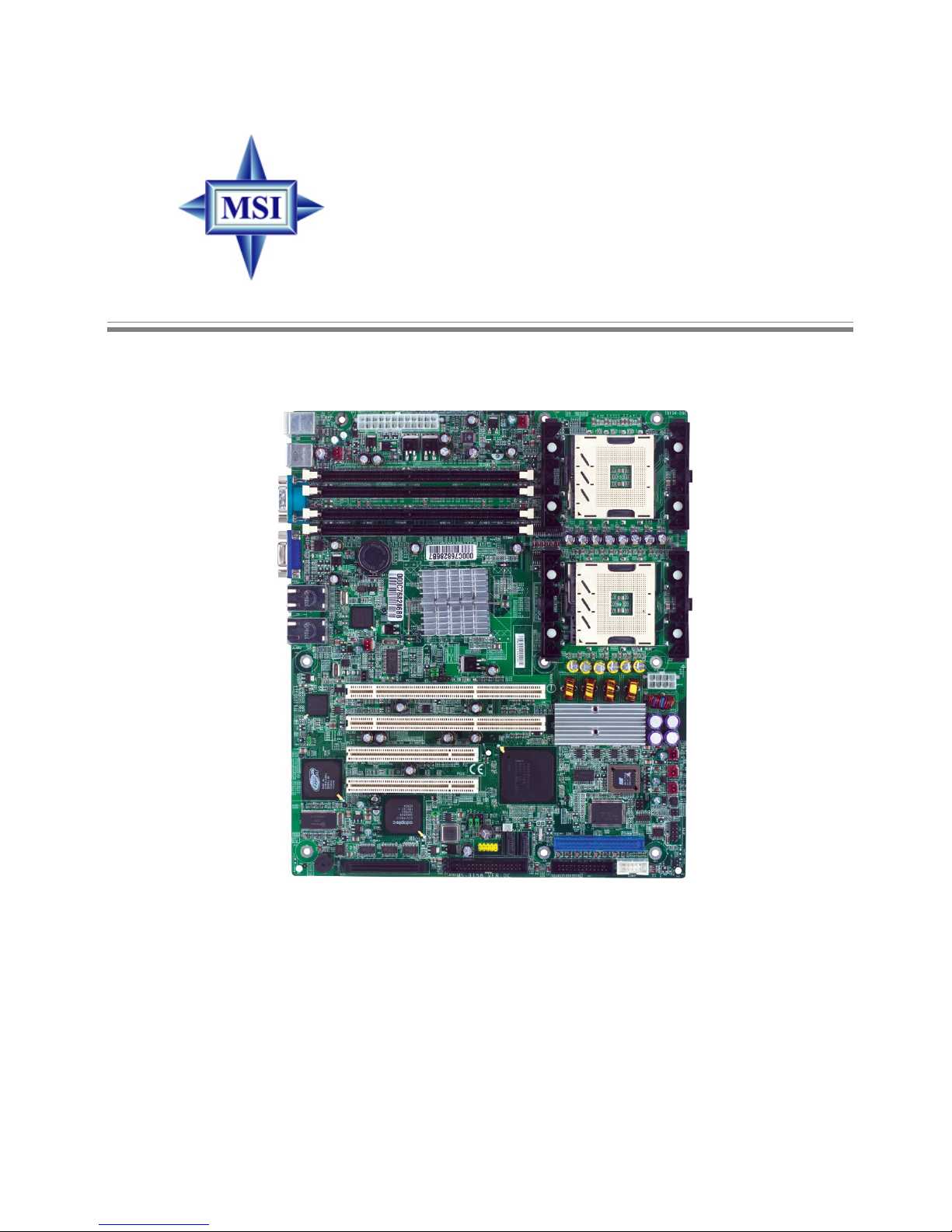
E7210 MasterX Series
MS-9156 ATX Server Board
Page 2
ii
Manual Rev: 1.1
Release Date: April 2004
FCC-A Radio Frequency Interference Statement
This equipment has been tested and found to comply with the limits for a class
A digital device, pursuant to part 15 of the FCC rules. These limits are designed
to provide reasonable protection against harmful interference when the equipment is operated in a commercial environment. This equipment generates, uses
and can radiate radio frequency energy and, if not installed and used in accordance with the instruction manual, may cause harmful interference to radio
communications. Operation of this equipment in a residential area is likely to
cause harmful interference, in which case the user will be required to correct
the interference at his own expense.
Notice 1
The changes or modifications not expressly approved by the party responsible for compliance could void the user’s authority to operate the equipment.
Notice 2
Shielded interface cables and A.C. power cord, if any, must be used in order to
comply with the emission limits.
VOIR LA NOTICE D’INSTALLATION AVANT DE RACCORDER AU
RESEAU.
Micro-Star International
MS-9156
This device complies with Part 15 of the FCC Rules. Operation is subject to
the following two conditions:
(1) this device may not cause harmful interference, and
(2) this device must accept any interference received, including interference
that may cause undesired operation.
Page 3

iii
Copyright Notice
The material in this document is the intellectual property of MICRO-STAR
INTERNATIONAL. We take every care in the preparation of this document,
but no guarantee is given as to the correctness of its contents. Our products
are under continual improvement and we reserve the right to make changes
without notice.
Trademarks
All trademarks are the properties of their respective owners.
Intel® and Pentium® are registered trademarks of Intel Corporation.
PS/2 and OS®/2 are registered trademarks of International Business Machines
Corporation.
Windows® 95/98/2000/NT/XP are registered trademarks of Microsoft
Corporation.
Netware® is a registered trademark of Novell, Inc.
Award® is a registered trademark of Phoenix T echnologies Ltd.
AMI® is a registered trademark of American Megatrends Inc.
Revision History
Revision Revision History Date
V1.1 Marketing name change April 2004
for PCB 1.X & 3.X
T echnical Support
If a problem arises with your system and no solution can be obtained from the
user’s manual, please contact your place of purchase or local distributor.
Alternatively, please try the following help resources for further guidance.
V isit the MSI website for FAQ, technical guide, BIOS updates, driver
updates, and other information: http://www .msi.com.tw/
Contact our technical staff at: support@msi.com.tw
Page 4

iv
1. Always read the safety instructions carefully.
2 . Keep this User’s Manual for future reference.
3 . Keep this equipment away from humidity.
4 . Lay this equipment on a reliable flat surface before setting it up.
5. The openings on the enclosure are for air convection hence protects the
equipment from overheating. DO NOT COVER THE OPENINGS.
6 . Make sure the voltage of the power source and adjust properly 1 10/220V
before connecting the equipment to the power inlet.
7. Place the power cord such a way that people can not step on it. Do not
place anything over the power cord.
8. Always Unplug the Power Cord before inserting any add-on card or module.
9. All cautions and warnings on the equipment should be noted.
1 0 . Never pour any liquid into the opening that could damage or cause electri-
cal shock.
11. If any of the following situations arises, get the equipment checked by a
service personnel:
††
††
† The power cord or plug is damaged.
††
††
† Liquid has penetrated into the equipment.
††
††
† The equipment has been exposed to moisture.
††
††
† The equipment has not work well or you can not get it work according
to User’s Manual.
††
††
† The equipment has dropped and damaged.
††
††
† The equipment has obvious sign of breakage.
12. DO NOT LEAVE THIS EQUIPMENT IN AN ENVIRONMENT
UNCONDITIONED, STORAGE TEMPERA TURE ABOVE 600 C (1400F), IT
MA Y DAMAGE THE EQUIPMENT.
Safety Instructions
警告使用者:
這是甲類的資訊產品,在居住的環境中使用時,可能會造成無線電干
擾,在這種情況下,使用者會被要求採取某些適當的對策。
CAUTION: Danger of explosion if battery is incorrectly replaced.
Replace only with the same or equivalent type recommended by the
manufacturer.
Page 5

v
CONTENTS
FCC-A Radio Frequency Interference Statement ..........................................iii
Copyright Notice ........................................................................................... iii
Trademarks....................................................................................................iii
Revision History ...........................................................................................iii
Technical Support ......................................................................................... iii
Safety Instructions ....................................................................................... v
Chapter 1. Getting Started ........................................................................ 1-1
Mainboard Specifications ....................................................................1-2
Mainboard Layout ............................................................................... 1-6
MSI Special Features ...........................................................................1-9
PC Alert™ III ................................................................................. 1-9
Chapter 2. Hardware Setup ....................................................................... 2-1
Quick Components Guide.....................................................................2-2
Central Processing Unit: CPU ..............................................................2-5
CPU Installation Procedures for Socket 604 ..................................2-6
Installing the Retention Module ...................................................2-7
Installing the Non-Intel CPU Cooler ..............................................2-8
Installing the Intel CPU Cooler .................................................... 2-10
Removing the Retention Module ................................................ 2-11
Memory.............................................................................................. 2-12
Memory Speed/CPU FSB Support Matrix ................................... 2-12
Memory Population Rules........................................................... 2-12
Installing DDR Modules .............................................................. 2-13
Power Supply ..................................................................................... 2-14
SSI 24-Pin Power Connector: POWER1 ....................................... 2-14
SSI 8-Pin Power Connector: POWER2 ......................................... 2-14
Back Panel .......................................................................................... 2-15
Floppy Disk Drive Connector: JFDD ............................................ 2-16
Fan Power Connectors: CPUF AN1/2, SYSTEMF AN1/2/3/4 ........2-16
Page 6

vi
Connectors.........................................................................................2-16
IDE Connectors: IDE1, IDE2 ........................................................ 2-17
Serial AT A RAID 0, 1 Connectors: SAT A1, SATA2 ..................... 2-18
SAT A RAID 0, 1, 10 Connectors: J10, J11, J12, J13 (Optional) ..... 2-19
LAN LED Connectors: JACT1, JACT2 ........................................ 2-20
Front Panel Connector: JFP1 ....................................................... 2-20
Silicon Image SA T A LED Connector: JS_LED ............................. 2-21
Front USB Connector: JUSB1...................................................... 2-21
Ultra320 SCSI Connector: SCSI 1 (Optional) ............................... 2-22
SCSI LED Connector: J10 (Optional) ........................................... 2-22
System Status LED Header: F AUL T_LED....................................2-23
5-pin I2C Bus Connector: IPMB .................................................. 2-23
Serial Port Connector: COM 2 ..................................................... 2-23
Parallel Port Header: CN11 ...........................................................2-24
Jumpers .............................................................................................. 2-25
VGA Control Jumper: J9 ............................................................... 2-25
Clear CMOS Jumper: JBA T.......................................................... 2-25
PCI-X Device Jumper: J1 .............................................................. 2-26
PCI-X Speed Jumper: J2............................................................... 2-26
82541 LAN Control Jumper: J3 .................................................... 2-26
System Configure Jumper: J6....................................................... 2-27
BIOS Flash Jumper: J7 ................................................................. 2-27
Slots ................................................................................................... 2-28
PCI (Peripheral Component Interconnect) Slots.......................... 2-28
PCI Interrupt Request Routing .................................................... 2-28
Chapter 3. BIOS Setup.............................................................................. 3-1
Entering Setup...................................................................................... 3-2
Control Keys .................................................................................3-2
Getting Help .................................................................................. 3-3
The Main Menu ...................................................................................3-4
Page 7

vii
Standard CMOS Features.....................................................................3-6
Advanced BIOS Features.....................................................................3-8
Advanced Chipset Features ............................................................... 3-14
Integrated Peripherals ........................................................................ 3-16
Power Management Setup.................................................................. 3-21
PC Health Status ................................................................................ 3-23
Frequency/Voltage Control ................................................................ 3-24
Load Fail-Safe/Optimized Defaults...................................................... 3-25
Set Supervisor/User Password........................................................... 3-26
Appendix A: SCSI BIOS Setup (Optional) ................................................A-1
Entering SCSI BIOS .............................................................................A-2
Control Keys ................................................................................A-2
Selecting the SCSI Channel ..........................................................A-2
Selecting the Management Type ..................................................A-2
Configure/View SCSI Controller Settings ............................................A-4
SCSI Bus Interface Definitions .....................................................A-4
Additional Options.......................................................................A-5
BIOS Information..........................................................................A-9
Disk Utilities ...................................................................................... A-10
Appendix B: Adaptec SAT A RAID Utility for Intel ICH-HR (Optional) .....B-1
Introduction ........................................................................................ B-2
1. Overview................................................................................... B-2
2. Operating System Compatibility ............................................... B-2
3. Storage Requirements ............................................................... B-2
4. Features .................................................................................... B-2
5. Storage Management Software Overview................................. B-3
Installing the Driver ............................................................................. B-4
1. Installing the Driver in a New W indows System ....................... B-4
2. Installing the Driver in an Existing W indows System................ B-5
3. Installing Red Hat Linux 7.3 or 8.0 ............................................ B-6
Page 8

viii
4. Installing SuSE Linux 8.0 or 8.1 ................................................. B-7
Installing Adaptec Storage Manager – Browser Edition ..................... B-8
1. Overview................................................................................... B-8
2. Supported Browsers ................................................................. B-8
3. T ypical, Custom, and Compact Installations............................. B-9
4. Installing Adaptec Storage Manager on Windows................. B-10
5. Installing Adaptec Storage Manager on Linux........................ B-13
Using Adaptec Storage Manager – Browser Edition......................... B-14
1. Overview................................................................................. B-14
2. Architecture Overview ............................................................ B-15
3. Logging In .............................................................................. B-16
4. Installing a Security Certificate ............................................... B-17
5. Registering Your Software ...................................................... B-17
6. The Basics .............................................................................. B-18
Adaptec RAID Configuration Utility................................................. B-23
1. Using the Array Configuration Utility .................................... B-24
2. Using the Disk Utilities ........................................................... B-28
Glossary ............................................................................................ B-29
Page 9

1-1
Getting Started
Thank you for choosing the E7210 MasterX Series (MS-
9156 v1.X/v3.X) ATX server boards. The E7210 MasterX Series
are superior computer mainboards based on Intel® E7210 &
Hance Rapids chipsets for optimal system efficiency . Designed
to fit the advanced Intel® Xeon™ processors in the 604 pin
package, the E7210 MasterX Series provide a solution for frontend and general purpose server/workstation in the entry-level
and mid-range market segment.
Chapter 1. Getting
Started
Getting Started
Page 10

1-2
MS-9156 ATX Server Board
Mainboard Specifications
T arget Segment
h T ar get in the entry-level and mid-range, front-end and general purpose server
market segments
CPU
h The second-generation of microprocessors using the Intel® NetBurst™
microarchitecture
h Supports Single/Dual Intel® Xeon™ with 1MB L3 cache processors
Chipset
h Intel® E7210 MCH (Memory Controller Hub)
- Supports 64-bit FSB frequencies of 400MHz & 533MHz
- Supports CSA (Communication Streaming Architecture) interface
- Supports DDR266/DDR333 unregistered non-ECC or ECC DDR DIMMs
h Intel® Hance Rapids ICH (I/O Controller Hub)
- Supports up to 4 USB 2.0 ports
- 1- or 2-channel Ultra AT A/100 Bus Master IDE controller
- 2 Serial AT A host controllers
- SMBus 2.0 controller
- I/O APIC
- AC’97 2.2 interface
- PCI-X 1.0 interface
- PCI 2.2 interface
Memory Bus Feature
h Supports unbufferred ECC DDR266/333 memory interface
h Supports four 184-pin DDR DIMMs up to 4GB
Feature Xeon™
L2 Cache 512 KB
L3 Cache 1MB
Data Bus Transfer Rate 3.2 GB/s or 4.27GB/s
Multi-Processor Support 1-2 CPUs
Manageability Features Intel and OEM EEPROMS and thermal
sensor on package
Package PGA 604
Operating Voltage 1.475 V
Page 11

1-3
Getting Started
Slots
h T wo PCI-X (64-bit/66MHz) slots
h T wo PCI (32-bit/33MHz) slots
HDD Interface
h E7210 MasterX-FS:
- SCSI interface supported by Adaptec AIC-7901 Ultra-320 SCSI controller
- Serial AT A RAID interface supported by Intel® Hance Rapids ICH (with 2
SATA connectors onboard/can connect up to 2 Serial ATA drives)
- Ultra AT A/100 Bus Master IDE interface supported by Intel® Hance Rapids
ICH (with 1 IDE connector onboard/can connect up to 2 Ultra ATA drives)
h E7210 MasterX-F A2R:
- Serial AT A RAID interface supported by Intel® Hance Rapids ICH (with 2
SATA connectors onboard/can connect up to 2 Serial ATA drives)
- Ultra AT A/100 Bus Master IDE interface supported by Intel® Hance Rapids
ICH (with 2 IDE connectors onboard/can connect up to 4 Ultra A TA drives)
h E7210 MasterX-F A6R:
- Serial A TA RAID interface supported by Intel® Hance Rapids ICH & Silicon
Image SiI 3114 PCI to four-port Serial ATA host controller (with 6 SATA
connectors onboard/can connect up to 6 Serial ATA drives)
- Ultra AT A/100 Bus Master IDE interface supported by Intel® Hance Rapids
ICH (with 2 IDE connectors onboard/can connect up to 4 Ultra A TA drives)
On-Board Peripherals
h On-Board Peripherals include:
- 1 floppy port supports 2 FDDs with 360K, 720K, 1.2M, 1.44M and
2.88Mbytes
- 2 serial ports (COM1 & COM2)
- 1 VGA port
- 4 USB 2.0 ports (Rear * 2/ Front * 2)
- 2 RJ45 LAN jacks
Network
h Intel® 82547GI Gigabit Ethernet Controller
h Intel® 82541GI Gigabit Ethernet Controller
Power Management Features
h Wake up on LAN (WOL), USB, PCI, Mouse
Page 12

1-4
MS-9156 ATX Server Board
h RTC alarm
h Supports ACPI S1, S4, and S5 functions
System Management
h SMBus (I2C)
h Hardware monitoring
h Thermal protection
h Chassis intrusion
BIOS
h 4 Mbit Flash EEPROM
h PCI 2.2 compliant, VPD, and DMI
h SMBIOS 2.3, ACPI 2.0
h Supports PXE boot protocol
h APM 1.2, WOL, WOR
h PC2001 system design compliant
Dimension
h Form Factor: 12” x 10.16”
Mounting
h 17 mounting holes in total, including CPU fan mounting holes
MSI Reminds Y ou...
Enabling the functionality of Hyper-Threading Technology for
your computer system requires ALL of the following platform
Components:
*CPU : Intel® Pentium® 4 or Xeon™ Processors with HT
Technology;
*Chipset: Intel® Chipsets that support HT Technology;
*BIOS: A BIOS that supports HT Technology and has it enabled;
*OS: An operating system that supports HT Technology.
For more information on Hyper-threading Technology, go to:
http://www.intel.com/info/hyperthreading
Page 13
1-5
Getting Started
MSI Reminds Y ou...
Please refer to Table 1 for 2D modes supporting both CRT and
LCD. The table specifies the minimum memory requirements for
various display resolutions, refresh rates and color depths.
Video
h Integrated ATI Rage™ XL graphics controller
- Built-in DVD decoding
- Integrated TMDS transmitter with support for Digital Flat Panel (DFP)
monitors
- Onboard 8MB V ideo SDRAM
Mode Refresh Minimum Amount of Memory Required
rate(Hz)
640x480 60
640X480 7 2
640X480 7 5
640X480 9 0
640X480 100
800X600 6 0
800X600 7 0
800X600 7 5
800X600 9 0
800X600 100
1024X768 6 0
1024X768 7 2
1024X768 7 5
1024X768 9 0
1024X768 100
1280x1024 43
1280x1024 60
1280x1024 70
1280x1024 72
1600x1200 66
1600x1200 76
8bpp 16bpp 24bpp 32bpp
2MB 2MB 2MB 2MB
2MB 2MB 2MB 2MB
2MB 2MB 2MB 2MB
2MB 2MB 2MB 2MB
2MB 2MB 2MB 2MB
2MB 2MB 2MB 4MB
2MB 2MB 2MB 4MB
2MB 2MB 2MB 4MB
2MB 2MB 2MB 4MB
2MB 2MB 2MB 4MB
2MB 2MB 4MB 4MB
2MB 2MB 4MB 4MB
2MB 2MB 4MB 4MB
2MB 2MB 4MB 4MB
2MB 2MB 4MB 4MB
2MB 4MB 4MB 6MB
2MB 4MB 4MB 6MB
2MB - 4MB 6MB
2MB - 4MB 6MB
4MB 4MB 6MB 8MB
4MB 4MB 6MB -
T able 1. 2D Modes (TFT or CR T)
Shading indicates modes not supported by TFT
Page 14
1-6
MS-9156 ATX Server Board
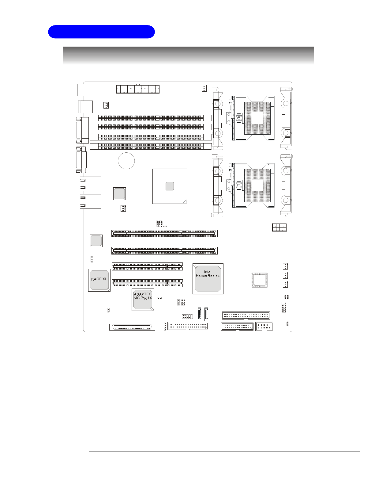
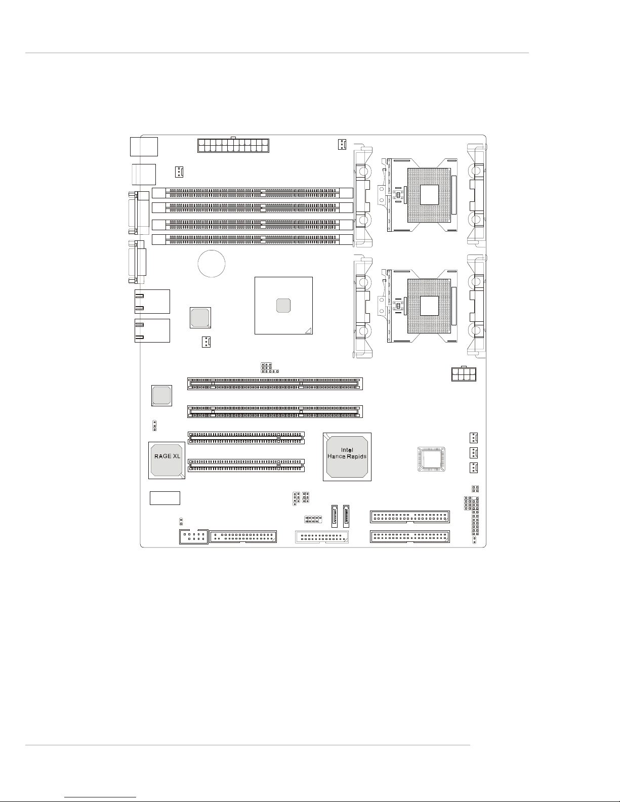
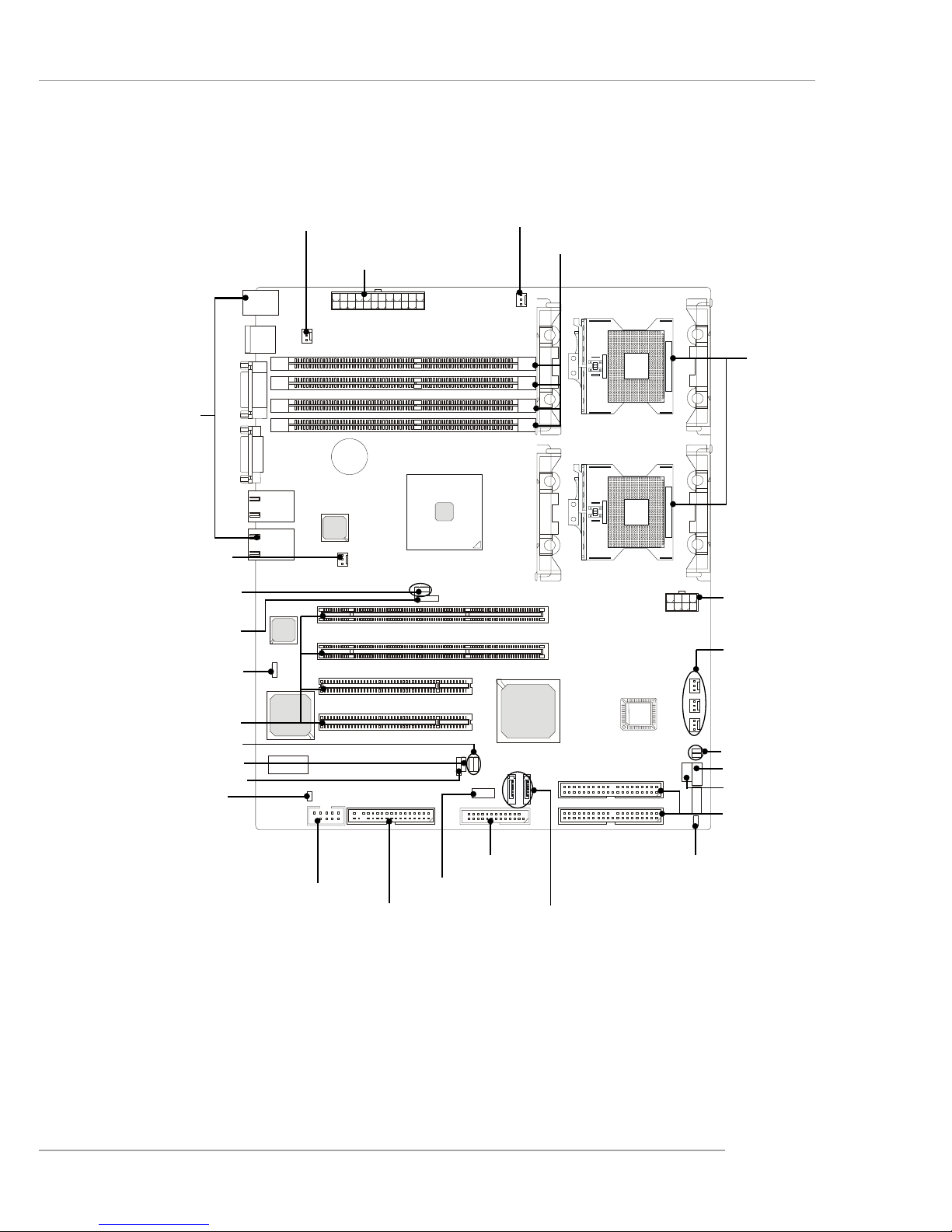
Mainboard Layout
E7210 MasterX-FS (MS-9156 v1.X) Server Board
- SCSI interface supported by Adaptec AIC-7901 Ultra-320 SCSI controller
- Serial AT A RAID interface supported by Intel® Hance Rapids ICH (with 2
SATA connectors onboard/can connect up to 2 Serial ATA drives)
- Ultra AT A/100 Bus Master IDE interface supported by Intel® Hance Rapids ICH (with 1 IDE connector onboard/can connect up to 2 Ultra ATA
drives)
DIMM3
DIMM1
DIMM4
DIMM2
POWER1
BATT
+
SYSTEMFAN4
J1
Intel
E7210
PCIX 1
PCIX 2
T: Mo use
B:Keyboard
LAN
LAN
USB
Ports
COM1
VGA1
POWER2
SYSTEMFAN1
J2
IPMB
PCI 1
PCI 2
IDE1
JFDD
CN11
JUSB1
JFP1
JACT2
JACT1
S
A
T
A
1
S
A
T
A
2
CPUFAN2
SYSTEMFAN2
SYSTEMFAN3
BIOS
SCSI 1
JBAT
J10
J3
J6
J9
J7
COM2
FAULT_LED
Intel
82547GI
Intel
82541GI
CPU2
CPU1
m
P
G
A
6
0
4
m
P
G
A
6
0
4
CPUFAN1
Page 15
1-7
Getting Started
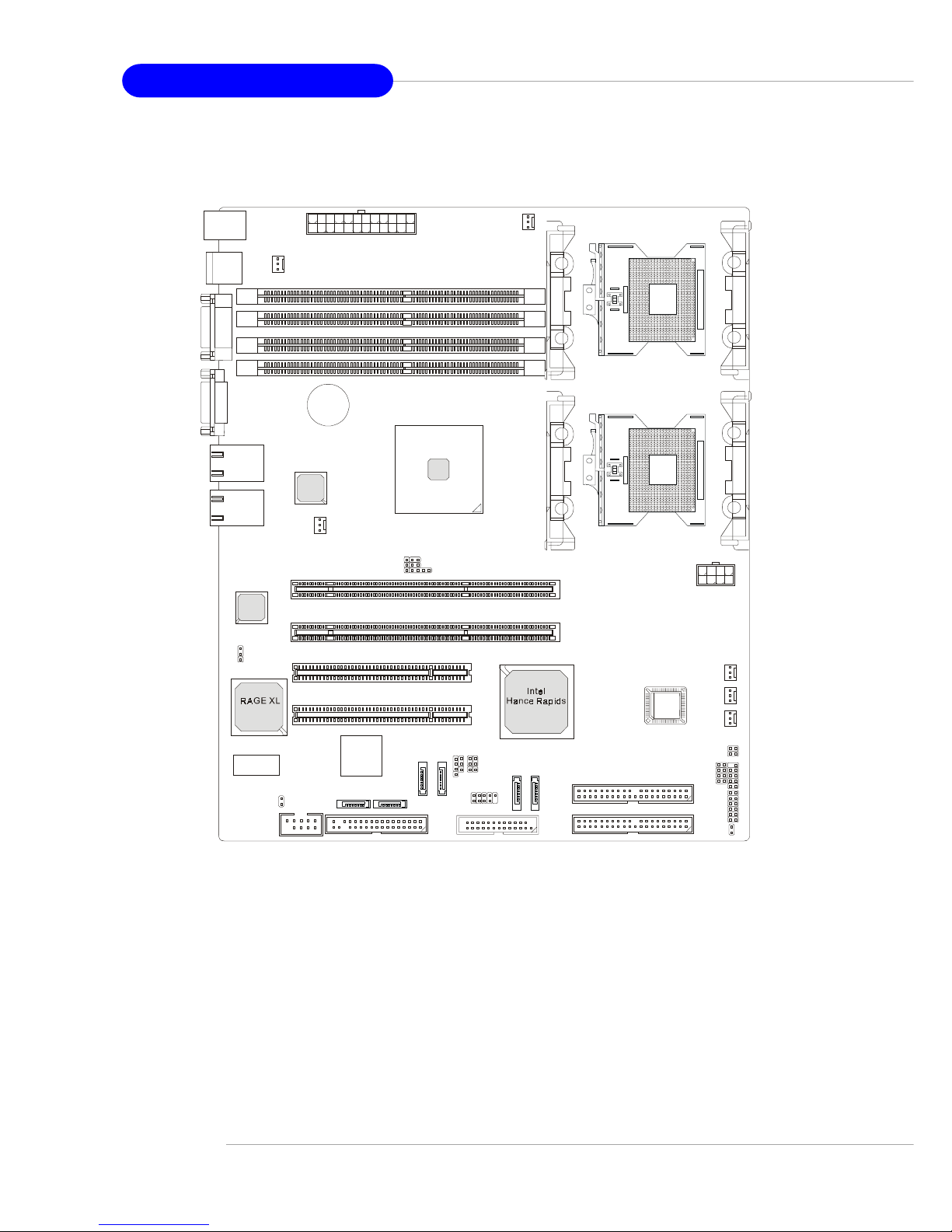
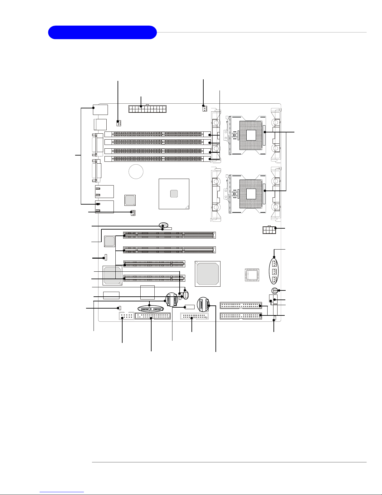
E7210 MasterX-F A2R (MS-9156 v3.X) Server Board
- Serial AT A RAID interface supported by Intel® Hance Rapids ICH (with 2
SATA connectors onboard/can connect up to 2 Serial ATA drives)
- Ultra AT A/100 Bus Master IDE interface supported by Intel® Hance Rapids ICH (with 2 IDE connectors onboard/can connect up to 4 Ultra AT A
drives)
DIMM3
DIMM1
DIMM4
DIMM2
POWER1
BATT
+
CPUFAN1
SYSTEMFAN4
J1
PCIX 1
PCIX 2
USB
Ports
T: Mo use
B:Keyboard
LAN
LAN
COM1
VGA1
POWER2
SYSTEMFAN1
J2
IPMB
PCI 1
PCI 2
IDE2
IDE1
JFDD
JUSB1
JFP1
JACT2
JACT1
S
A
T
A
1
S
A
T
A
2
CPUFAN2
SYSTEMFAN2
SYSTEMFAN3
BIOS
JBAT
J3
J6J9J7
COM2
CN11
FAULT_L E D
Intel
E7210
CPU2
CPU1
m
P
G
A
6
0
4
m
P
G
A
6
0
4
JSCSI
JS_LED
Page 16
1-8
MS-9156 ATX Server Board
E7210 MasterX-F A6R (MS-9156 v3.X) Server Board
- Serial AT A RAID interface supported by Intel® Hance Rapids ICH & Sili-
con Image SiI 3114 PCI to four-port Serial ATA host controller (with 6
SATA connectors onboard/can connect up to 6 Serial ATA drives)
- Ultra AT A/100 Bus Master IDE interface supported by Intel® Hance Rapids ICH (with 2 IDE connectors onboard/can connect up to 4 Ultra AT A
drives)
DIMM3
DIMM1
DIMM4
DIMM2
POWER1
BATT
+
CPUFAN1
SYSTEMFAN4
J1
PCIX 1
PCIX 2
USB
Ports
T: Mo use
B:Keyboard
LAN
LAN
COM1
VGA1
POWER2
SYSTEMFAN1
J2
IPMB
PCI 1
PCI 2
IDE2
IDE1
JFDD
JUSB1
JFP1
JACT2
JACT1
S
A
T
A
1
S
A
T
A
2
J12
J11
J10
J13
CPUFAN2
SYSTEMFAN2
SYSTEMFAN3
BIOS
JBAT
J3
J6J9J7
COM2
CN11
Silicon Image
Sil 3114
FAULT_L E D
Intel
E7210
CPU2
CPU1
m
P
G
A
6
0
4
m
P
G
A
6
0
4
JSCSI
JS_LED
Page 17
1-9
Getting Started
MSI Special Features
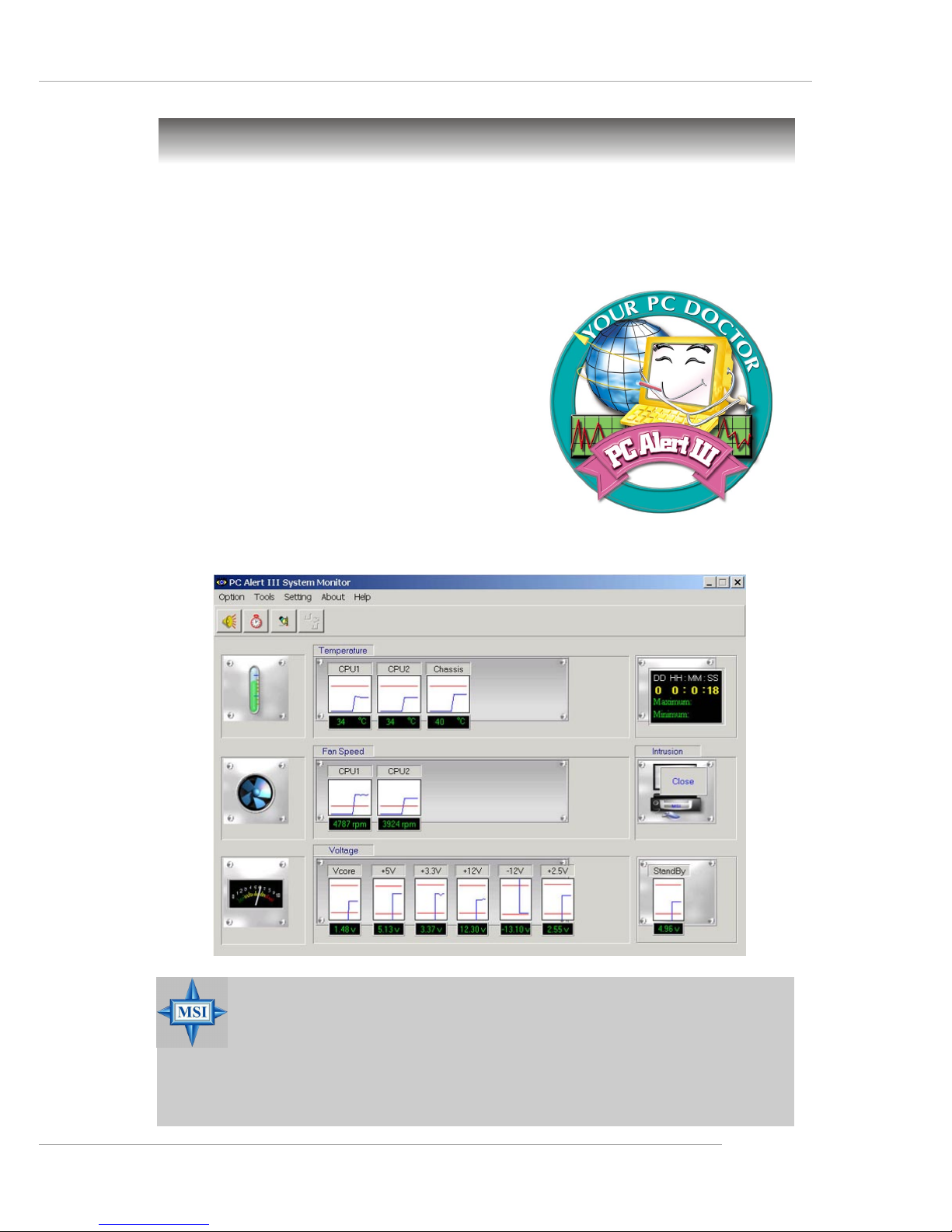
PC Alert™ III
The PC AlertTM III is a utility you can find in the CD-ROM disk. The
utility is just like your PC doctor that can detect the following PC hardware status during
real time operation:
Ü monitor CPU & system temperatures
Ü monitor fan speed(s)
Ü monitor system voltage
Ü monitor chassis intrusion
If one of the items above is abnormal,
the program main screen will be immediately
shown on the screen, with the abnormal item
highlighted in red. This will continue to be
shown until user disables the warning.
MSI Reminds Y ou...
1. Items shown on PC Alert™ III vary depending on your system
status.
2. The mainboard bound with mBMC chip (Server Management
Features) won’t support PC Alert™ III.
Page 18

2-1
Hardware Setup
Chapter 2. Hardware
Setup
Hardware Setup
This chapter provides you with the information about hardware setup procedures. While doing the installation, be careful
in holding the components and follow the installation
procedures. For some components, if you install in the wrong
orientation, the components will not work properly.
Use a grounded wrist strap before handling computer
components. Static electricity may damage the components.
Page 19
2-2
MS-9156 ATX Server Board
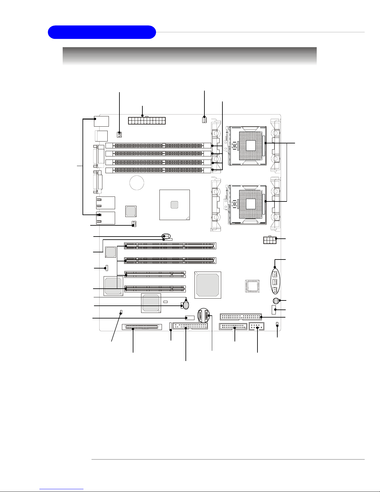
Quick Components Guide
E7210 MasterX-FS (MS-9156 v1.X) Server Board
- SCSI interface supported by Adaptec AIC-7901 Ultra-320 SCSI controller
- Serial AT A RAID interface supported by Intel® Hance Rapids ICH (with 2
SATA connectors onboard/can connect up to 2 Serial ATA drives)
- Ultra AT A/100 Bus Master IDE interface supported by Intel® Hance Rapids ICH (with 1 IDE connector onboard/can connect up to 2 Ultra ATA
drives)
m
P
G
A
6
0
4
m
P
G
A
6
0
4
CPU, p.2-5
POWER1, p.2-14
CPUFAN1, p.2-16
Back Panel
I/O, p.2-15
IDE1,p.2-17
DIMM1~4, p.2-12
CPUFAN2,
SYSTEMFAN2/3,
p.2-16
FAULT_LED, p.2-23
IPMB, p.2-23
PCI Slots, p.2-28
J9, p.2-25
SCSI1, p.2-22
JUSB1, p.2-21
JFP1, p.2-20
JACT1/2, p.2-20
SYSTEMFAN4,
p.2-16
J3, p.2-26
CN11, p.2-24
JBAT, p.2-25
J1/J2, p.2-26
J10, p.2-22
SATA1/2, p.2-18
COM2, p.2-23
J6/J7, p.2-27
SYSTEMFAN1, p.2-16
JFDD, p.2-16
POWER2, p.2-14
Page 20
2-3
Hardware Setup
E7210 MasterX-F A2R (MS-9156 v3.X) Server Board
- Serial AT A RAID interface supported by Intel® Hance Rapids ICH (with 2
SATA connectors onboard/can connect up to 2 Serial ATA drives)
- Ultra AT A/100 Bus Master IDE interface supported by Intel® Hance Rapids ICH (with 2 IDE connectors onboard/can connect up to 4 Ultra AT A
drives)
BIOS
m
P
G
A
6
0
4
m
P
G
A
6
0
4
CPU, p.2-5
POWER1, p.2-14
CPUFAN1, p.2-16
Back Panel
I/O, p.2-15
IDE1/2,p.2-17
DIMM1~4, p.2-12
CPUFAN2,
SYSTEMFAN2/3,
p.2-16
FAULT_LED, p.2-23
IPMB, p.2-23
PCI Slots, p.2-28
J9, p.2-25
JUSB1, p.2-21
JFP1, p.2-20
JACT1/2, p.2-20
SYSTEMFAN4,
p.2-16
J3, p.2-26
CN11, p.2-24
JBAT, p.2-25
J1/J2, p.2-26
SATA1/2, p.2-18
J6/J7, p.2-27
SYSTEMFAN1, p.2-16
JFDD, p.2-16
POWER2, p.2-14
COM2, p.2-23
JS_LED, p.2-21
JSCSI, p.2-22
Page 21
2-4
MS-9156 ATX Server Board
E7210 MasterX-F A6R (MS-9156 v3.X) Server Board
- Serial AT A RAID interface supported by Intel® Hance Rapids ICH & Sili-
con Image SiI 3114 PCI to four-port Serial ATA host controller (with 6
SATA connectors onboard/can connect up to 6 Serial ATA drives)
- Ultra AT A/100 Bus Master IDE interface supported by Intel® Hance Rapids ICH (with 2 IDE connectors onboard/can connect up to 4 Ultra AT A
drives)
BIOS
m
P
G
A
6
0
4
m
P
G
A
6
0
4
CPU, p.2-5
POWER1, p.2-14
CPUFAN1, p.2-16
Back Panel
I/O, p.2-15
IDE1/2,p.2-17
DIMM1~4, p.2-12
FAULT_LED, p.2-23
IPMB, p.2-23
PCI Slots, p.2-28
J9, p.2-25
JUSB1, p.2-21
JFP1, p.2-20
JACT1/2, p.2-20
J3, p.2-26
CN11, p.2-24
JBAT, p.2-25
J1/J2, p.2-26
SATA1/2, p.2-18
J6/J7, p.2-27
SYSTEMFAN1, p.2-16
JFDD, p.2-16
POWER2, p.2-14
COM2, p.2-23
J10/J11/J12/J13,
p.2-19
SYSTEMFAN4,
p.2-16
CPUFAN2,
SYSTEMFAN2/3,
p.2-16
JS_LED, p.2-21
JSCSI, p.2-22
Page 22
2-5
Hardware Setup
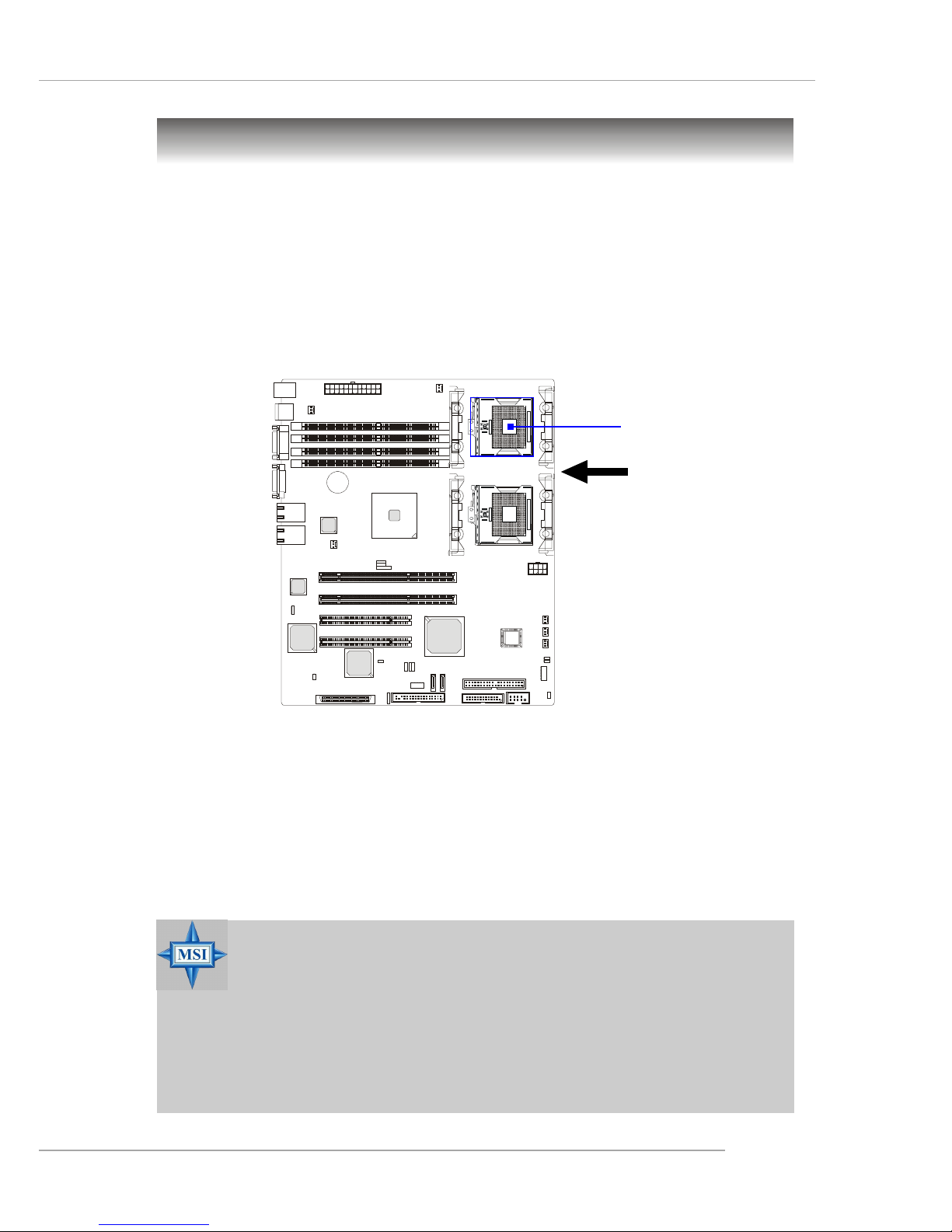
The mainboard supports Single/Dual Intel® Xeon™ processor(s). The
mainboard uses two CPU sockets called Socket 603/604 for easy CPU
installation. You can install SINGLE or DUAL CPUs on the board to meet
your own needs. Keep the following points in mind before installing CPU(s):
1. If SINGLE CPU is intended, always install the CPU on the CPU1
socket.
2. To install DUAL CPUs on the board, you must use the same type
of CPUs running at the same FSB frequency.
When you are installing the CPU, make sure the CPU has a Heat Sink
and a cooling fan attached on the top to prevent overheating. If you do
not find the Heat Sink and cooling fan, contact your dealer to purchase and
install them before turning on the computer.
Central Processing Unit: CPU
MSI Reminds Y ou...
Overheating will seriously damage the CPU and system, always
make sure the cooling fan can work properly to protect the CPU
from overheating.
The system temperature needs to remain under 45°C.
We highly recommend that the direction of inlet air should follow
the direction indicated above for better cooling effect.
m
P
G
A
6
0
4
m
P
G
A
6
0
4
CPU1
Recommended inlet air direction
Page 23
2-6
MS-9156 ATX Server Board
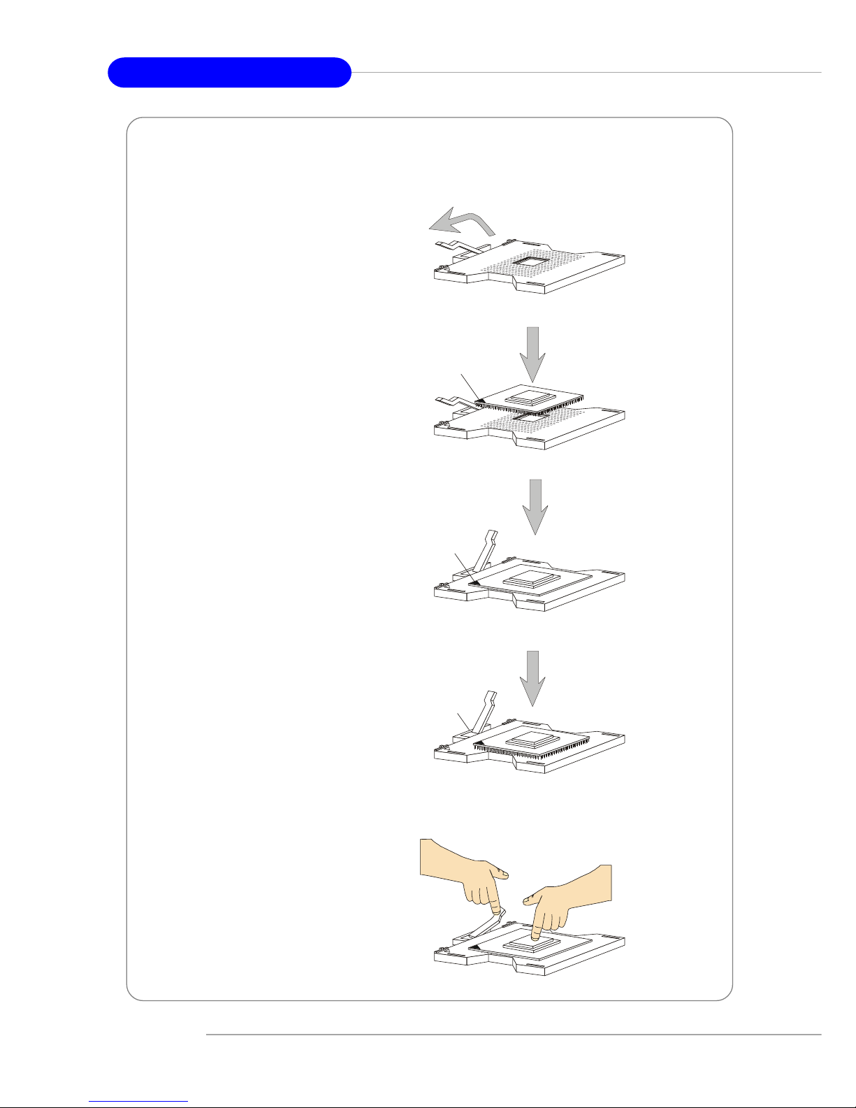
1. Please turn off the power and
unplug the power cord before
installing the CPU.
2. Pull the lever sideways away
from the socket. Make sure
to raise the lever up to a 170degree angle.
3. Look for the gold arrow. The
gold arrow should point towards the lever pivot. The
CPU can only fit in the correct orientation.
4. If the CPU is correctly
installed, the pins should be
completely embedded into the
socket and can not be seen.
Please note that any violation
of the correct installation procedures may cause permanent
damages to your mainboard.
5. Press the CPU down firmly
into the socket and close the
lever. As the CPU is likely to
move while the lever is being
closed, always close the lever
with your fingers pressing
tightly on top of the CPU to
make sure the CPU is properly and completely embedded into the socket.
CPU Installation Procedures for Socket 604
Open Lever
Sliding
Plate
Gold arrow
Gold arrow
Gold arrow
Correct CPU placement
Incor rect CP U placement
X
O
Close
Lever
Press down
the CPU
Page 24
2-7
Hardware Setup
MSI Reminds Y ou...
Mainboard photos shown in this section are for demonstration
of the cooler installation for Socket 604 CPUs only. The appearance of your mainboard may differ depending on the model
you purchase.
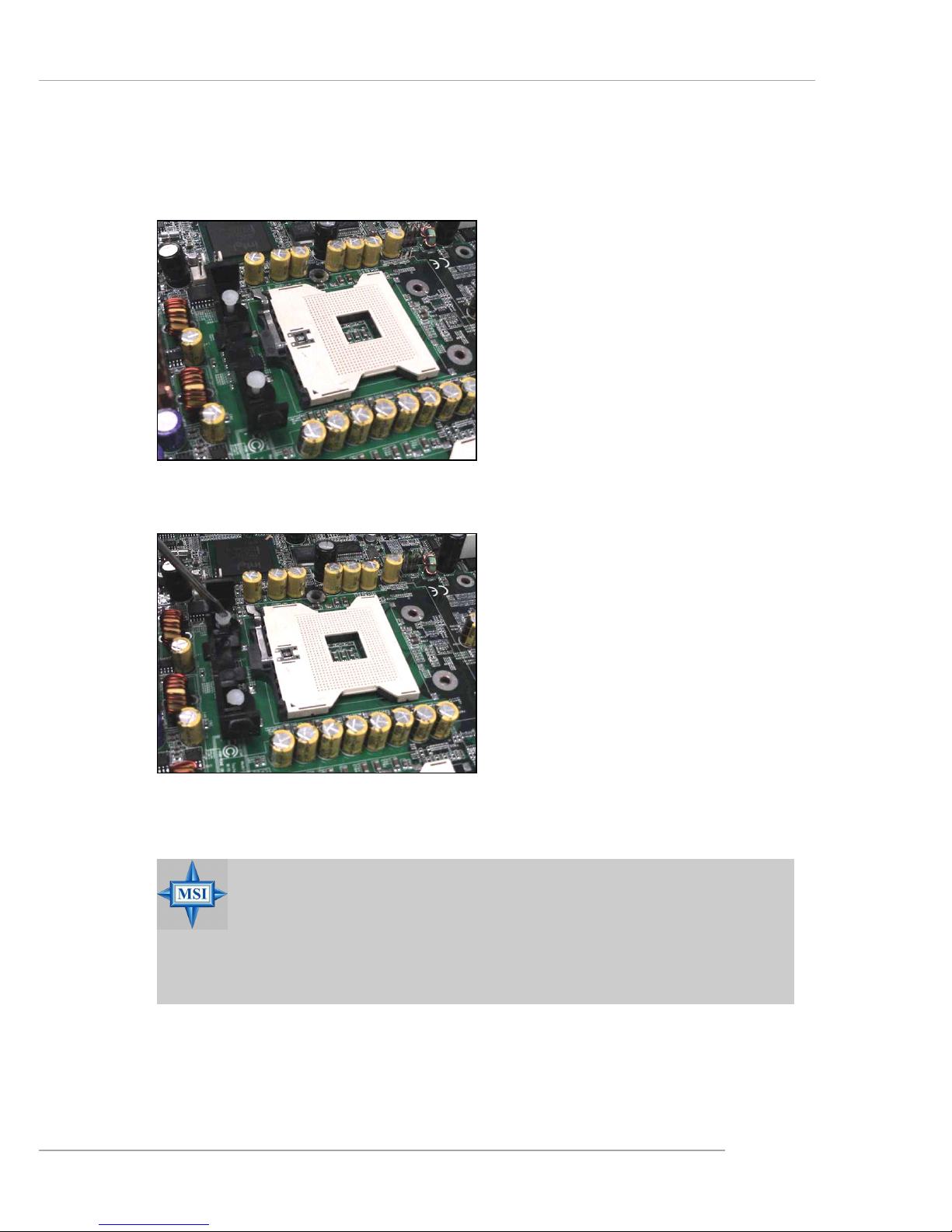
Installing the Retention Module
1. Locate the four retention module holes around the Socket 604
on the mainboard.
2. Align the retention module with
two holes on one side of the
Socket 604.
3. Use a flat-headed screw driver
to press the white push pins into
place.
4. Repeat the same procedures on
the other side of the Socket 604.
Page 25
2-8
MS-9156 ATX Server Board
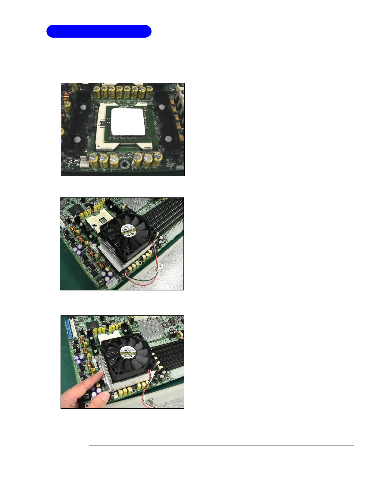
Installing the Non-Intel CPU Cooler
1. T ake out your CPU. Look for the
gold arrow on the CPU. The gold
arrow should point towards the
lever pivot. Note that the CPU
can only fit in the correct
orientation. (refer to p. 2-4)
2. Apply some heat paste all over
the top of the CPU.
3. Position the cooler right on top
of the CPU.
4. Press the clip into the hook.
Page 26
2-9
Hardware Setup
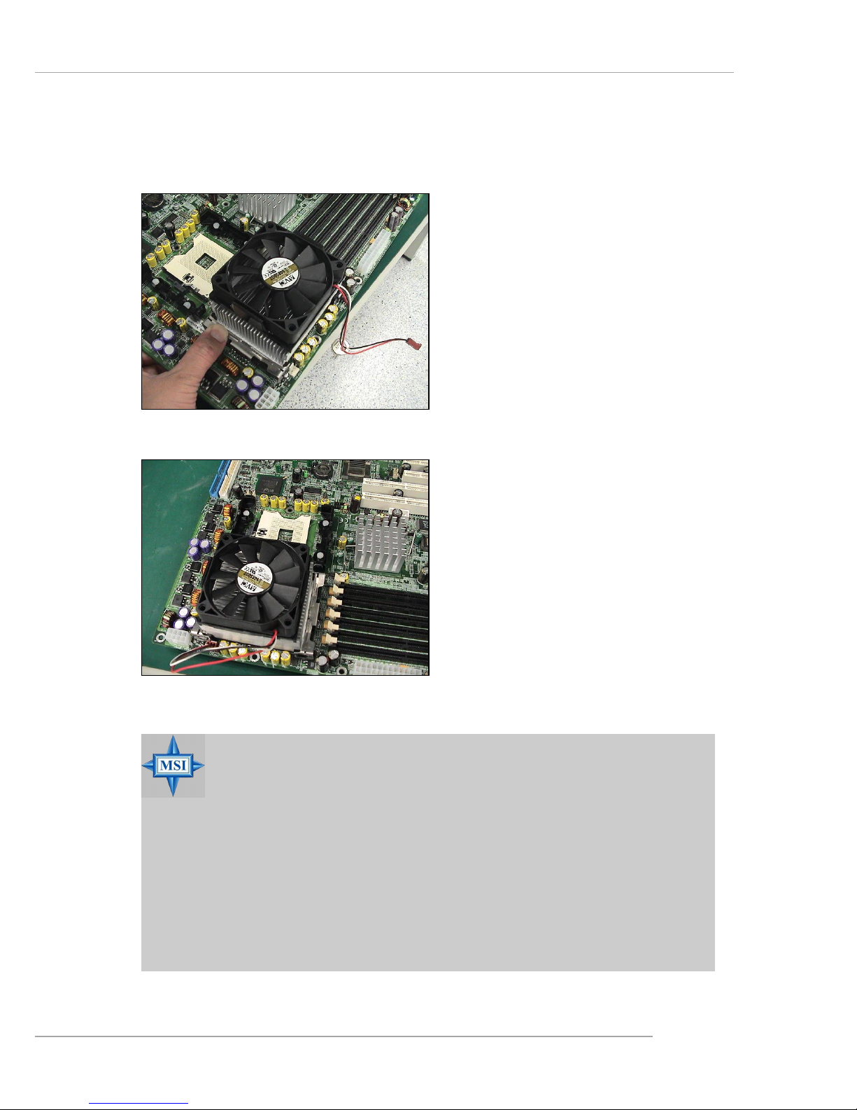
5 . Push the other clip into the hook.
6. Repeat the same procedures on
the other retention module of
the Socket 604.
7. Connect the CPU fan power cord
to CPUFAN1 and the cooler installation is complete.
Note: If dual processors are
installed, connect the second
CPU fan power cord to
CPUFAN2.
MSI Reminds Y ou...
Overheating
Overheating will seriously damage the CPU and system, always make sure the cooling fan can work properly to protect
the CPU from overheating.
Replacing the CPU
While replacing the CPU, always turn off the ATX power supply or unplug the power supply’s power cord from grounded
outlet first to ensure the safety of CPU.
Page 27
2-10
MS-9156 ATX Server Board
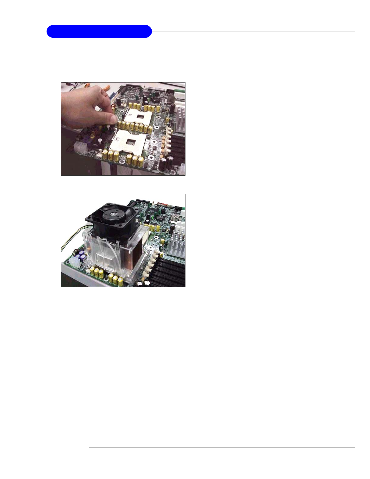
Installing the Intel CPU Cooler
1 . Install the Intel PWT-U cooler set
in accordance with instructions
described in its accompanying
user’s guide.
2. We suggest that you install the
PWT-U cooler in a 5U tower
chassis and place it on top of the
heatsink for better cooling
effects.
Page 28
2-11
Hardware Setup
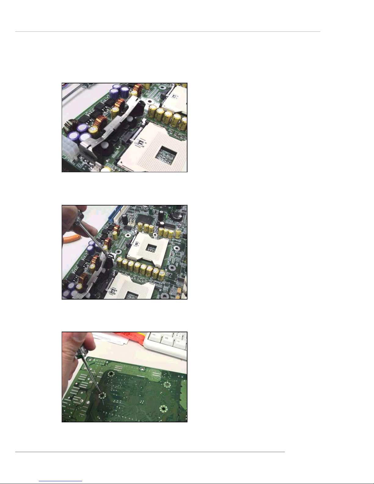
Removing the Retention Module
1. Locate the retention module and
clips on the mainboard.
2 . Use a flat-headed screw driver to
push one side of the clip off the
hook.
3. Flip over the mainboard and use
the screw driver to push the white
push pin off the hole.
Page 29

2-12
MS-9156 ATX Server Board
Memory modules can be installed in any combination as follows:
Memory
The mainboard provides 4 slots for 184-pin DDR DIMM (Double InLine Memory Module) modules and supports the memory size up to 4 GB. Y ou
can install PC2100/DDR266 or PC2700/DDR333 DDR SDRAM modules on the
DDR DIMM slots (DIMM 1~4).
Memory Population Rules
The mainboard supports both single- & dual-channel modes. Install at
least one DIMM module on the slots. Each DIMM slot supports up to a maximum size of 1GB. Y ou can install either single- or double-sided modules to meet
your own needs. In dual-channel mode, make sure that you install memory
modules of the same type and density on DDR DIMMs “in pairs” -- {DIMM1 &
DIMM3} {DIMM2 & DIMM4}.
Memory Speed/CPU FSB Support Matrix
DDR266 DDR333
FSB400 OK N/A
FSB533 OK OK
MSI Reminds Y ou...
If DDR266 memory is running with FSB400 CPU, memory frequency will drop from DDR266 to DDR200.
DIMM1
DIMM2
DIMM3
DIMM4
Channel B
Channel A
Page 30
2-13
Hardware Setup
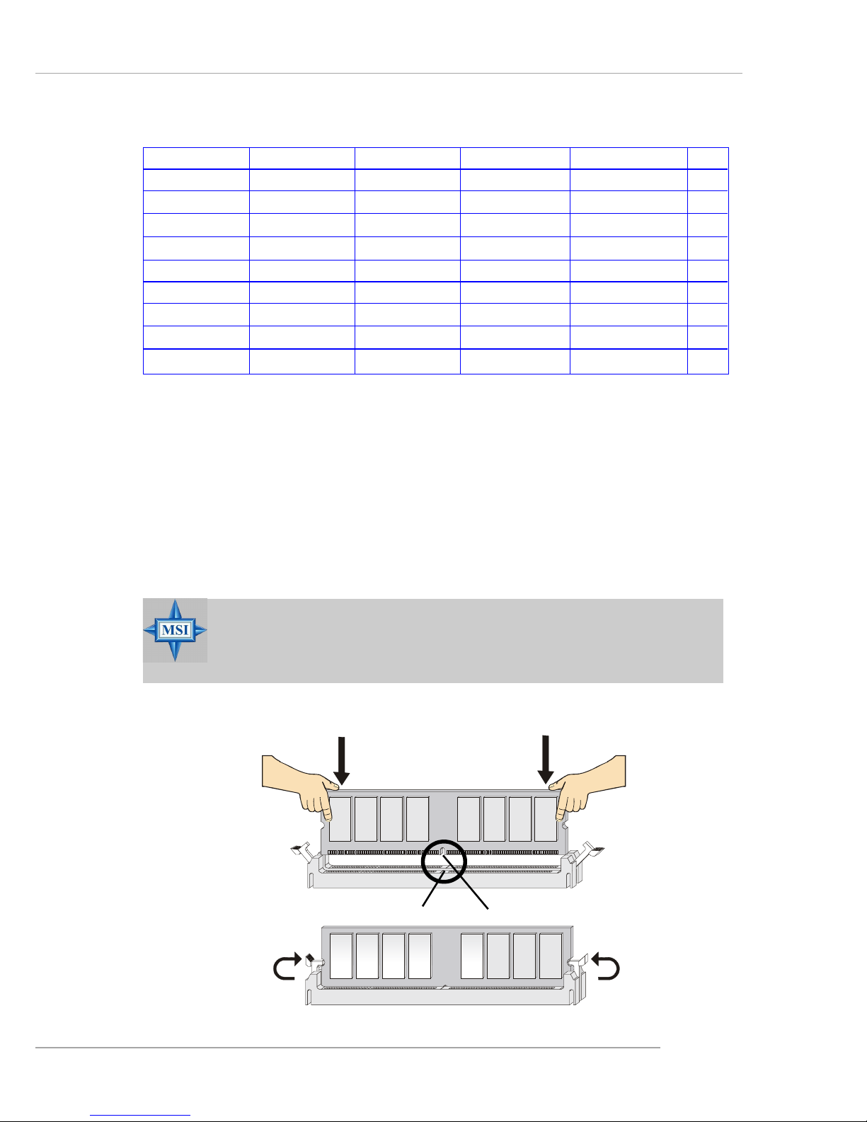
Installing DDR Modules
1. The DDR DIMM has only one notch on the center of module. The module will only fit in the right orientation.
2. Insert the DIMM memory module vertically into the DIMM slot. Then
push it in until the golden finger on the memory module is deeply inserted in the socket.
3. The plastic clip at each side of the DIMM slot will automatically close.
Volt
Notch
MSI Reminds Y ou...
You can barely see the golden finger if the module is properly
inserted in the socket.
DIMM1 DIMM2 DIMM3 DIMM4 System Density Mode
128MB~1GB 128MB~1GB S
128MB~1GB 128MB~1GB S
128MB~1GB 128MB~1GB S
128MB~1GB 128MB~1GB S
128MB~1GB 128MB~1GB 256MB~2GB S
128MB~1GB 128MB~1GB 256MB~2GB S
128MB~1GB 128MB~1GB 256MB~2GB D
128MB~1GB 128MB~1GB 256MB~2GB D
128MB~1GB 128MB~1GB 128MB~1GB 128MB~1GB 512MB~4GB D
S: Single-Channel Mode D: Dual-Channel Mode
Page 31

2-14
MS-9156 ATX Server Board
Power Supply
The mainboard supports SSI power supply for the power system. Before inserting the power supply connector, always make sure that all components are installed properly to ensure that no damage will be caused.
SSI 24-Pin Power Connector: POWER1
This connector allows you to connect to an SSI power supply. To connect to the SSI power supply, make sure the plug of the power supply is inserted in the proper orientation and the pins are aligned. Then push down the
power supply firmly into the connector.
SSI 8-Pin Power Connector: POWER2
This connector provides 12V power output to the CPU.
POWER1
12
1
24
13
POWER2
1
8
5
4
PIN SIGNAL
13 +3.3V
14 -12V
15 GND
16 PS-ON#
17 GND
18 GND
19 GND
20 3VSB
21 +5V
22 +5V
23 +5V
24 GND
PIN SIGNAL
1 +3.3V
2 +3.3V
3 GND
4 +5V
5 GND
6 +5V
7 GND
8 PWR OK
9 5VSB
10 +12V
11 +12V
12 +3.3V
POWER1 Pin Definition
PIN SIGNAL
5 +12V
6 +12V
7 +12V
8 +12V
PIN SIGNAL
1 GND
2 GND
3 GND
4 GND
POWER2 Pin Definition
MSI Reminds Y ou...
Power supply of 300watt (and up) is highly recommended for
system stability.
Page 32

2-15
Hardware Setup
Back Panel
Mouse
Keyboard USB COM 1 LANVGA LAN
RJ-45 LAN Jack
Link Indicator
8 1
Activity Indicator
Gigabit LAN Pin Definition
USB Ports
1 2 3 4
Serial Port
PIN SIGNAL
1DCD
2 SIN
3 SOUT
4 DTR
5 GND
6 DSR
7 RTS
8 CTS
9RI
VGA Port
Mouse/Keyboard Connector
Pin1
Mouse/KBD
DATA
Pin2 NC
Pin3 GNDPin4 VCC
Pin5
Mouse/KBD Clock
Pin6 NC
PIN SIGNAL
1 RED
2 GREEN
3 BLUE
4 N/C
5 GND
6 GND
7 GND
8 GND
9 +5V
10 GND
1 1 N/C
12 SDA
13 Horizontal Sync
14 Vertical Sync
15 SCL
1 2 3 4 5
6 7 8 9
1
5
11
15
PIN SIGNAL
1 VCC
2 -Data
3 +Data
4 GND
PIN SIGNAL DESCRIPTION
1 D0P Differential Pair 0+
2 D0N Differential Pair 03 D1P Differential Pair 1+
4 D2P Differential Pair 2+
5 D2N Differential Pair 26 D1N Differential Pair 17 D3P Differential Pair 3+
8 D3N Differential Pair 3-
Page 33

2-16
MS-9156 ATX Server Board
The mainboard provides connectors to connect to FDD, IDE HDD, case,
LAN, USB Ports, CPU/system power supply fans, ... and etc.
Floppy Disk Drive Connector: JFDD
The mainboard provides a standard floppy disk drive connector that
supports 360K, 720K, 1.2M, 1.44M and 2.88M floppy disk types.
Connectors
JFDD
Fan Power Connectors: CPUF AN1/2, SYSTEMF AN1/2/3/4
The CPUF AN1/2 (processor fans) & SYSTEMFAN1/2/3/4 (system fan)
support system cooling fan with +12V. It supports three-pin head connector.
When connecting the wire to the connectors, always note that the red wire is
the positive and should be connected to the +12V ; the black wire is Ground and
should be connected to GND. If the mainboard has a System Hardware Monitor chipset on-board, you must use a specially designed fan with speed sensor
to take advantage of the CPU fan control.
SYSTEMFAN1/2/3/4
SENSOR
+12V
GND
CPUFAN1/2
SENSOR
+12V
GND
MSI Reminds Y ou...
Always consult the vendors for proper CPU cooling fans.
Page 34

2-17
Hardware Setup
MSI Reminds Y ou...
If you install two hard disks on cable, you must configure the
second drive to Slave mode by setting its jumper. Refer to the
hard disk documentation supplied by hard disk vendors for
jumper setting instructions.
IDE Connectors: IDE1, IDE2
The southbridge integrates 2-channel Ultra ATA/100 Bus Master IDE
controller that provides PIO mode 0~4, Bus Master, and Ultra DMA 33/66/100
function.
The E7210 MasterX-FS offers one IDE connector onboard for connection of up to two hard disk drives, CD-ROM, 120MB Floppy (reserved for
future BIOS) and other devices.
The E7210 MasterX-F A2R & E7210 MasterX-FA6R offers two IDE connectors onboard for connection of up to four hard disk drives, CD-ROM, 120MB
Floppy (reserved for future BIOS) and other devices.
IDE1 (Primary IDE Connector)
The first hard drive should always be connected to IDE1. IDE1 can
connect a Master and a Slave drive. You must configure second hard
drive to Slave mode by setting the jumper accordingly.
IDE2 (Secondary IDE Connector)
IDE2 can also connect a Master and a Slave drive.
IDE1
IDE2
Page 35

2-18
MS-9156 ATX Server Board
Serial A TA RAID 0, 1 Connectors: SA TA1, SA TA2
The southbridge Intel® Hance Rapids ICH provides a hybrid solution
that combines two independent SATA ports for support of up to two Serial
ATA (Serial ATA RAID) drives and utilizes Adaptec Embedded Serial ATA
RAID Software to support RAID levels 0 and 1 for easy management of the
storage subsystems. Both connectors support 1st generation serial ATA data
rates of 150 MB/s and are fully compliant with Serial AT A 1.0 specifications.
PIN SIGNAL PIN SIGNAL
1 GND 2 TXP
3 TXN 4 GND
5 RXN 6 RXP
7 GND
SATA1/2 Pin Definition
SATA2SATA1
7
1
7
1
MSI Reminds Y ou...
Please do not fold the Serial ATA cable into 90-degree angle.
Otherwise, the loss of data may occur during transmission.
Connect to SATA1 or SATA2
Take out the dust cover and
connect to the hard disk devices
Optional Serial A TA cable
Page 36

2-19
Hardware Setup
PIN SIGNAL PIN SIGNAL
1 GND 2 TXP
3 TXN 4 GND
5 RXN 6 RXP
7 GND
J10/J11/J12/J13 Pin Definition
Serial ATA RAID 0, 1, 10 Connectors: J10, J11, J12, J13
(Optional)
The mainboard provides optional Serial ATA RAID 0, 1, 10 connectors
supported by Silicon Image SiI 3114 controller.
The SiI 3114 is compliant with the Serial AT A 1.0 specification (150 MB/s
data rates), supporting four independent SAT A channels and a 32-bit 33/66MHz
PCI bus. It comes with Silicon Image's robust SA T A base and SA T ARaid software
drivers, which currently support JBOD, RAID 0, RAID 1, and RAID 10 for the
Windows, Linux and Netware operating systems. Incorporating a single Phase
Lock Loop (PLL) architecture supporting all four ports, the SiI 3114 features
integrated Serial ATA Link and PHY logic based on Silicon Image's proven,
high-speed Multi-layer Serial Link (MSLTM) architecture.
For more information on Serial A TA RAID 0, 1, 10, please refer to (Silicon
Image SiI 3114) Serial ATA RAID 0, 1, 10 Quick User’ s Guide.
Connect to J10/J11/J12/J13
Take out the dust cover and
connect to the hard disk devices
Optional Serial A T A cable
MSI Reminds Y ou...
Please do not fold the Serial ATA cable into 90-degree angle.
Otherwise, the loss of data may occur during transmission.
J12
7
1
J13
7
1
J11 J10
1
177
Page 37

2-20
MS-9156 ATX Server Board
Front Panel Connector: JFP1
The mainboard provides one front panel connector for electrical connection to the front panel switches and LEDs. The JFP1 is compliant with Intel
®
Front Panel I/O Connectivity Design Guide.
LAN LED Connectors: JACT1, JACT2
The LAN LED connectors are used to connect to LAN LEDs, which
show the activity of the LAN. JACT1 is for JLAN 1 jack and the JACT2 is for
JLAN2 jack. Both JLAN1 & JLAN2 jacks are located on the back panel.
1
2
9
10
JFP1
HDD
LED
Reset
Switch
Power
LED
Power
Switch
PIN SIGNAL DESCRIPTION
1 HD_LED_P Hard disk LED pull-up
2 FP PWR/SLP MSG LED pull-up
3 HD_LED_N Hard disk active LED
4 FP PWR/SLP MSG LED pull-up
5 RST_SW_N Reset Switch low reference pull-down to GND
6 PWR_SW_P Power Switch high reference pull-up
7 RST_SW_P Reset Switch high reference pull-up
8 PWR_SW_N Power Switch low reference pull-down to GND
9 RSVD_DNU Reserved. Do not use.
JFP1 Pin Definition
JACT1
JACT2
+
+
-
-
Page 38

2-21
Hardware Setup
Front USB Connector: JUSB1
The mainboard provides one USB 2.0 pin header JUSB1 (optional USB 2.
0 bracket available) that is compliant with Intel® I/O Connectivity Design Guide.
USB 2.0 technology increases data transfer rate up to a maximum throughput of
480Mbps, which is 40 times faster than USB 1.1, and is ideal for connecting
high-speed USB interface peripherals such as USB HDD, digital cameras,
MP3 players, printers, modems and the like.
PIN SIGNAL PIN SIGNAL
1 USBPWR 2 USBPWR
3 USBP4- 4 USBP55 USBP4+ 6 USBP5+
7 GND 8 GND
9 NC 10 USBOC
Pin Definition
1
2
9
10
JUSB1
Silicon Image SA TA LED Connector: JS_LED
This connector is used to connect LEDs for showing the activities of SiI
3114 Serial AT A devices.
JS_LED
1 2
7 8
PIN SIGNAL PIN SIGNAL
1 VCC3 2 J10 LED
3 VCC3 4 J11 L ED
5 VCC3 6 J12 LED
7 VCC3 8 J13 LED
Pin Definition
Page 39

2-22
MS-9156 ATX Server Board
Ultra320 SCSI Connector: SCSI 1 (Optional)
SCSI (Small Computer System Interface) is a parallel interface standard
for attaching peripheral devices to computers. Ultra320 SCSI is the seventh
generation of SCSI I/O technology , and has a maximum data rate speed of 320
MB/sec. SCSI’s commitment to backward compatibility and legacy support are
the primary reasons for its durability as an I/O interface, making SCSI the industry standard for disk drive connection in virtually all high-performance servers.
SCSI LED Connector: J10/JSCSI (Optional)
This connector is used to connect to a LED for showing the activity of
SCSI devices attached to SCSI 1 connector.
Pin Description Pin Description
1 +DB(12) 35 -DB(12)
2 +DB(13) 36 -DB(13)
3 +DB(14) 37 -DB(14)
4 +DB(15) 38 -DB(15)
5 +DB(P1) 39 -DB(P1)
6 +DB(0) 40 -DB(0)
7 +DB(1) 41 -DB(1)
8 +DB(2) 42 -DB(2)
9 +DB(3) 43 -DB(3)
10 +DB(4) 44 -DB(4)
11 +DB(5) 45 -DB(5)
12 +DB(6) 46 -DB(6)
13 +DB(7) 47 -DB(7)
14 +DB(P) 48 -DB(P)
15 GROUND 49 GROUND
16 DIFFSENS 50 GROUND
17 TERMPWR 5 1 TERMPWR
18 TERMPWR 5 2 TERMPWR
1 9 RESERVED 53 RESERVED
20 GROUND 54 GROUND
21 +ATN 55 -ATN
22 GROUND 56 GROUND
2 3 +BSY 57 -BSY
24 +ACK 58 -ACK
25 +RST 59 -RST
26 +MSG 60 -MST
27 +SEL 61 -SEL
28 +C/D 62 -C/D
29 +REQ 63 -REQ
30 +I/O 6 4 -I/O
31 +DB(8) 65 -DB(8)
32 +DB(9) 66 -DB(9)
33 +DB(10) 67 -DB(10)
34 +DB(11) 68 -DB(11)
68-Pin Ultra320 SCSI Connector
1
35
34
68
SCSI 1
PIN SIGNAL
1 VCC5
2 SCSI LED
3 HDD LED
4 VCC5
Pin Definition
1
J10/JSCSI
MSI Reminds Y ou...
SCSI LED connects to JFP1
HDD LED (storage LED) pins.
The J10/JSCSI is used to connect SCSI card LED signal.
Page 40

2-23
Hardware Setup
Serial Port Connector: COM 2
The mainboard offers one 9-pin header as serial port COM 2. The port is
a 16550A high speed communication port that sends/receives 16 bytes FIFOs.
You can attach a serial mouse or other serial devices directly to it.
PIN SIGNAL DESCRIPTION
1 DCD Data Carry Detect
2 SIN Serial In or Receive Data
3 SOUT Serial Out or Transmit Data
4 DTR Data T erminal Ready
5 GND Ground
6 DSR Data Set Ready
7 RTS Request T o Send
8 CTS Clear T o Send
9 RI Ring Indicate
Pin Definition
5-pin I2C Bus Connector: IPMB
The mainboard provides one I2C (also known as I2C) Bus connector for
users to connect to System Management Bus (SMBus) interface.
F AULT_LED
COM 2
1
9
82
System Status LED Header: F AULT_LED
Connect an LED to this header and the LED will lighten when the CPU,
system, or power fan shuts down.
PIN SIGNAL
1 SMBCLK
2 SMBDAT A
3 SMBALERT#
4 GND
5 VCC3
IPMB Pin Definition
IPMB
1
Page 41

2-24
MS-9156 ATX Server Board
Parallel Port Header: CN1 1
The mainboard provides a 25-pin header for connection to an optional
parallel port bracket. The parallel port is a standard printer port that supports
Enhanced Parallel Port (EPP) and Extended Capabilities Parallel Port (ECP) mode.
PIN SIGNAL DESCRIPTION
1 STROBE Strobe
2 DATA0 Data0
3 DATA1 Data1
4 DATA2 Data2
5 DATA3 Data3
6 DATA4 Data4
7 DATA5 Data5
8 DATA6 Data6
9 DATA7 Data7
10 ACK# Acknowledge
11 BUSY Busy
12 PE Paper End
1 3 SELECT Select
1 4 AUTO FEED# Automatic Feed
15 ERR# Error
1 6 INIT# Initialize Printer
17 SLIN# Select In
18 GND Ground
19 GND Ground
20 GND Ground
21 GND Ground
22 GND Ground
23 GND Ground
24 GND Ground
25 GND Ground
Pin Definition
13 1
14
25
Print Port
CN11
Page 42

2-25
Hardware Setup
VGA Control Jumper: J9
This jumper is used to enable or disable the onboard VGA.
The motherboard provides the following jumpers for you to set the
computer’s function. This section will explain how to change your
motherboard’s function through the use of jumpers.
Jumpers
MSI Reminds Y ou...
You can clear CMOS by shorting 2-3 pin while the system is off.
Then return to 1-2 pin position. Avoid clearing the CMOS while
the system is on; it will damage the mainboard.
Clear CMOS Jumper: JBA T
There is a CMOS RAM on board that has a power supply from external
battery to keep the data of system configuration. With the CMOS RAM, the
system can automatically boot OS every time it is turned on. If you want to
clear the system configuration, use the JBAT (Clear CMOS Jumper ) to clear
data. Follow the instructions below to clear the data:
Keep CMOS Clear CMOS
3
1
3
1
JBAT
1
J9 Enable VGADisable VGA
Page 43

2-26
MS-9156 ATX Server Board
PCI-X Device Jumper: J1
This jumper specifies the type of devices installed on the PCI-X slots.
PCI-X Speed Jumper: J2
The jumper is used to set the speed of the 64-bit PCI-X buses.
82541 LAN Control Jumper: J3
This jumper is used to enable/disable the onboard LAN function.
Disable LAN
1
3
Enable LAN
1
3
J3
1
J2
1
33MHz66MHz
1
3
1
3
J1
1
Non-PCIX DevicesPCIX Devices
1
3
1
3
Page 44

2-27
Hardware Setup
BIOS Flash Jumper: J7
This jumper is used to protect the BIOS boot block from virus infection.
When locked, the BIOS boot block cannot be accessed, making BIOS update
impossible. When BIOS update is intended, remove the jumper cap to disable
BIOS flash protection.
System Configure Jumper: J6
The J6 jumper determines which mode the system will enter while powered on. Under Normal Mode, the system will enter the assigned OS as usual.
Under Configure Mode, the system will directly enter BIOS setup utility. This
enables you to modify the BIOS configurations. Under Recovery Mode, you
have to insert certain boot disk into the floppy drive before powering on the
system. After powered on, the system will read the boot disk and enter DOS.
This enables you to update the BIOS with a Flash utility if necessary.
Disable BIOS
Flash Protection
1
3
Enable BIOS
Flash Protection
1
3
J7
1
1
3
1
3
1
3
Configure ModeNormal Mode Recovery Mode
J6
1
Page 45

2-28
MS-9156 ATX Server Board
Slots
PCI (Peripheral Component Interconnect) Slots
The PCI slots allow you to insert the expansion cards to meet your needs.
When adding or removing expansion cards, make sure that you unplug the
power supply first. Meanwhile, read the documentation for the expansion card
to make any necessary hardware or software settings for the expansion card,
such as jumpers, switches or BIOS configuration. Two PCI slot are conventional 32-bit PCI bus slots and the other two are 64-bit PCI bus (also called PCI-
X) slots.
32-bit PCI bus: The bus has 32 data lines and runs at 33MHz.
64-bit PCI-X bus: The bus has 64 data lines and runs at 66MHz. With
twice data lines and much faster PCI clock, the 64-bit PCI bus increases
the throughput and overall system performance.
PCI Interrupt Request Routing
The IRQ, acronym of interrupt request line and pronounced I-R-Q, are
hardware lines over which devices can send interrupt signals to the
microprocessor. The PCI IRQ pins are typically connected to the PCI bus INT
A# ~ INT D# pins as follows:
32-bit PCI Slots
(for 32-bit short cards only)
64-bit PCI-X Slots
(for 32-bit long cards,
64-bit short cards, &
64-bit long cards)
The motherboard provides two 32-bit Master PCI slots and two 64-bit
PCI-X slots.
Page 46

2-29
Hardware Setup
PCI-32 IRQ Routing (for ICH-HR)
PCI Device INT A INT B INT C INT D
PCI Slot 1 PIRQ#A PIRQ#B PIRQ#C PIRQ#D
PCI Slot 2 PIRQ#B PIRQ#C PIRQ#D PIRQ#A
82541GI LAN PIRQ#H
82547GI LAN PIRQ#F
VGA PIRQ#G
PCI-64 IRQ Routing
PCI Device INT A INT B INT C INT D
PCIX-64 Slot1 PX_IRQ#0 PX_IRQ#1 PX_IRQ#2 PX_IRQ#3
PCIX-64 Slot2 PX_IRQ#1 PX_IRQ#2 PX_IRQ#3 PX_IRQ#0
AIC-7901 SCSI PX_IRQ#2
Page 47

3-1
BIOS Setup
Chapter 3. BIOS Setup
This chapter provides information on the BIOS Setup program and allows you to configure the system for optimum use.
You may need to run the Setup program when:
An error message appears on the screen during the system
booting up, and requests you to run SETUP.
You want to change the default settings for customized
features.
BIOS Setup
Page 48

MS-9156 ATX Server Board
3-2
Entering Setup
Control Keys
Power on the computer and the system will start POST (Power On Self
Test) process. When the message below appears on the screen, press <DEL>
key to enter Setup.
Press DEL to enter SETUP
If the message disappears before you respond and you still wish to enter
Setup, restart the system by turning it OFF and On or pressing the RESET
button. You may also restart the system by simultaneously pressing <Ctrl>,
<Alt>, and <Delete> keys.
<↑> Move to the previous item
<↓> Move to the next item
<←> Move to the item in the left hand
<→> Move to the item in the right hand
<Enter> Select the item
<Esc> Jumps to the Exit menu or returns to the main menu from a submenu
<+/PU> Increase the numeric value or make changes
<-/PD> Decrease the numeric value or make changes
<F1> General help, only for Status Page Setup Menu and Option
Page Setup Menu
<F5> Restore the previous CMOS value from CMOS, only for Option
Page Setup Menu
<F6> Load Fail-Safe Defaults
<F7> Load Optimized Defaults
<F10> Save all the CMOS changes and exit
Page 49

3-3
BIOS Setup
Getting Help
After entering the Setup menu, the first menu you will see is the Main
Menu.
Main Menu
The main menu lists the setup functions you can make changes to. You
can use the arrow keys ( ↑↓ ) to select the item. The on-line description of the
highlighted setup function is displayed at the bottom of the screen.
Sub-Menu
If you find a right pointer symbol (as shown in the right view) appears
to the left of certain fields that means a submenu can be launched from this field. A
sub-menu contains additional options for a
field parameter. You can use arrow keys (
↑↓ ) to highlight the field and press <Enter>
to call up the sub-menu. Then you can use
the control keys to enter values and move from field to field within a submenu. If you want to return to the main menu, just press the <Esc >.
General Help <F1>
The BIOS setup program provides a General Help screen. You can call
up this screen from any menu by simply pressing <F1>. The Help screen lists
the appropriate keys to use and the possible selections for the highlighted
item. Press <Esc> to exit the Help screen.
MSI Reminds You...
The items under each BIOS category described in this chapter
are under continuous update for better system performance.
Therefore, the description may be slightly different from the latest BIOS and should be held for reference only.
Page 50

MS-9156 ATX Server Board
3-4
The Main Menu
Standard CMOS Features
Use this menu for basic system configurations, such as time, date etc.
Advanced BIOS Features
Use this menu to configure the special enhanced features.
Advanced Chipset Features
Use this menu to change the values in the chipset registers and optimize your
system’s performance.
Integrated Peripherals
Use this menu to specify your settings for integrated peripherals.
Power Management Setup
Use this menu to specify your settings for power management.
Once you enter Phoenix-Award BIOS CMOS Setup Utility, the Main
Menu will appear on the screen. The Main Menu displays eleven configurable
functions and two exit choices. Use arrow keys to move among the items and
press <Enter> to enter the sub-menu.
Page 51

3-5
BIOS Setup
PC Health Status
This entry shows your PC health status.
Frequency/V oltage Control
Use this menu to specify your settings for frequency/voltage control.
Load Fail-Safe Defaults
Use this menu to load the BIOS default values for minimal but stable system
performance.
Load Optimized Defaults
Use this menu to load the BIOS default values that are factory settings for
optimal system operations.
Set Supervisor/User Password
Use this menu to set user and supervisor passwords.
Save & Exit Setup
Save changes to CMOS and exit setup.
Exit Without Saving
Abandon all changes and exit setup.
Page 52

MS-9156 ATX Server Board
3-6
Standard CMOS Features
The items inside Standard CMOS Features menu are divided into 10
categories. Each category includes none, one or more setup items. Use the
arrow keys to highlight the item you want to modify and use the <PgUp> or
<PgDn> keys to switch to the value you prefer.
Date (mm:dd:yy)
This allows you to set the system to the date that you want (usually the current
date). The format is <day><month> <date> <year>.
day Day of the week, from Sun to Sat, determined by
BIOS. Read-only.
month The month from Jan. through Dec.
date The date from 1 to 31 can be keyed by numeric
function keys.
year The year can be adjusted by users.
Time (hh:mm:ss)
This allows you to set the system time that you want (usually the current
time). The time format is <hour> <minute> <second>.
IDE Channel 0/1 Master/Slave
Press PgUp/<+> or PgDn/<-> to select Manual, None, Auto type. Note that
the specifications of your drive must match with the drive table. The hard disk
will not work properly if you enter improper information for this category. If
Page 53

3-7
BIOS Setup
your hard disk drive type is not matched or listed, you can use Manual to
define your own drive type manually.
If you select Manual, related information is asked to be entered to the following items. Enter the information directly from the keyboard. This information
should be provided in the documentation from your hard disk vendor or the
system manufacturer.
If the controller of HDD interface is SCSI, the selection shall be “None”. If
the controller of HDD interface is CD-ROM, the selection shall be “None”.
Access Mode The settings are CHS, LBA, Large, Auto.
Capacity The formatted size of the storage device.
Cylinder Number of cylinders.
Head Number of heads.
Precomp Write precompensation.
Landing Zone Cylinder location of the landing zone.
Sector Number of sectors.
Drive A/B
This item allows you to set the type of floppy drives installed. Available
options are [None], [360K, 5.25 in.], [1.2M, 5.25 in.], [720K, 3.5 in.], [1.44M, 3.5
in.], [2.88M, 3.5 in.]
Halt On
The setting determines whether the system will stop if an error is detected at
boot. A vailable options are:
[All Errors] The system stops when any error is detected.
[Disabled] The system doesn’t stop for any detected error.
[All, But Keyboard] The system doesn’t stop for a keyboard error.
[All, But Diskette] The system doesn’t stop for a disk error.
[All, But Disk/Key] The system doesn’t stop for either a disk or a
keyboard error.
Base/Extended/Total Memory
The three items show the memory status of the system. (Read-only)
Page 54

MS-9156 ATX Server Board
3-8
Advanced BIOS Features
Hard Disk Boot Priority
This setting determines the boot priority of the installed hard disks.
Virus Warning
The item is to set the Virus Warning feature for IDE Hard Disk boot sector
protection. If the function is enabled and any attempt to write data into this area
is made, BIOS will display a warning message on screen and beep. Setting
options: [Disabled], [Enabled].
Page 55

3-9
BIOS Setup
CPU L3 Cache
Level 3 cache is the extra cache built into motherboards between the
microprocessor and the main memory. Located away from the CPU, the L3
cache is slower than the L1 & L2 caches. This setting allows you to turn on
or off the L3 cache. Setting options: [Enabled], [Disabled].
Hyper-Threading Technology
With Intel® Hyper-Threading Technology, a single Hyper-Threading-enabled
processor can simultaneously process two threads of code, improving the performance of multi-threaded code running on a single processor platform. Setting this function to Enabled will improve overall system performance, in-
crease number of users a platform can support, improve reaction and response
time, and increase number of transaction that can be executed. Setting options:
[Enabled], [Disabled].
O/B SCSI & Slot Boot Order
This setting determines which PCI device’s option ROM will be executed first.
Setting options: [SCSI, Slot], [Slot, SCSI]. SCSI refers to the onboard SCSI 7901
and Slot refers to the PCI card installed.
Quick Power On Self Test
The option speeds up Power On Self Test (POST) after you power on the
computer.
First/Second/Third Boot Device
The items allow you to set the sequence of boot devices where BIOS attempts
to load the disk operating system. The settings are:
MSI Reminds You...
Enabling the functionality of Hyper-Threading Technology for your
computer system requires ALL of the following platform
Components:
*CPU: Intel® Pentium® 4 or Xeon™ Processors with HT
Technology;
*Chipset: Intel® Chipsets that support HT Technology;
*BIOS: A BIOS that supports HT Technology and has it enabled;
*OS: An operating system that supports HT Technology.
For more information on Hyper-threading Technology, go to:
http://www.intel.com/info/hyperthreading
Page 56

MS-9156 ATX Server Board
3-10
[Floppy] The system will boot from floppy drive.
[LS120] The system will boot from LS-120 drive.
[Hard Disk] The system will boot from the HDD.
[CDR O M ] The system will boot from the CD-ROM.
[ZIP100] The system will boot from AT API ZIP drive.
[LAN] The system will boot from the onboard
10/100 Network drive.
[Disabled] Disable this sequence.
Boot Other Device
Setting the option to [Enabled] allows the system to try to boot from other
devices if the system fails to boot from the 1st/2nd/3rd boot device.
Boot Up NumLock Status
This setting is to set the Num Lock status when the system is powered on.
Setting to On will turn on the Num Lock key when the system is powered on.
Setting to Off will allow users to use the arrow keys on the numeric keypad.
Setting options: [On], [Off].
Security Option
This specifies the type of BIOS password protection that is implemented. Settings are described below:
APIC Mode
This field is used to enable or disable the APIC (Advanced Programmable Inter-
Option Description
[Setup] The password prompt appears only when end users try to
run Setup.
[System] A password prompt appears every time when the com-
puter is powered on or when end users try to run Setup.
MSI Reminds You...
Available settings for “First/Second/Third Boot Device” vary depending on the bootable devices you have installed. For example, if
you did not install a floppy drive, the setting “Floppy” does not
show up.
Page 57

3-11
BIOS Setup
rupt Controller). Due to compliance with PC2001 design guide, the system is
able to run in APIC mode. Enabling APIC mode will expand available IRQ resources for the system. Settings: [Enabled] and [Disabled].
MPS V ersion Contr ol For OS
This field allows you to select which MPS (Multi-Processor Specification)
version to be used for the operating system. You need to select the MPS version supported by your operating system. To find out which version to use,
consult the vendor of your operating system. Settings: [1.4], [1.1].
Console Redirection
Console Redirection operates in host systems that do not have a monitor and
keyboard attached. This setting enables/disables the operation of console
redirection. When set to Enabled, BIOS redirects and sends all contents that
should be displayed on the screen to the serial COM port for display on the
terminal screen. Besides, all data received from the serial port is interpreted as
keystrokes from a local keyboard. Setting options: [Enabled], [Disabled].
Baud Rate
This setting specifies the transfer rate (bits per second) of Console Redirection.
Setting options: [9600], [19200], [38400], [57600], [115200].
Agent Connect Via
To operate the system’s console redirection, you need a terminal supporting
ANSI terminal protocol and a RS-232 null modem cable connected between
the host system and terminal(s). This field is a read-only field, which is used to
indicate the type of device connected between the host system and terminal
(s). NULL stands for a null modem.
Agent Wait Time (min)
This setting controls the timeout for terminals’ (console redirection) connection to the host system. Setting options: [1], [2], [4], [8] (Min).
Agent After Boot
This setting determines whether or not to keep terminals’ console redirection
running after the OS has booted. Setting options: [Disabled], [Enabled].
ASF Support
This setting disables/enables the ASF (Alert Standard Format) function. Setting options: [Disabled], [Enabled].
Page 58

MS-9156 ATX Server Board
3-12
DMI Event Log
This setting disables/enables the BIOS to log DMI (Desktop Management
Interface) events. Setting options: [Disabled], [Enabled].
Clear All DMI Event Log
When this setting is set to [Y es], the DMI event log will be cleared at next POST
stage. Then, the BIOS will automatically set this option to [No]. Setting options:
[Y es], [No].
View DMI Event Log
Press [Enter] to view all DMI event logs.
Mark DMI Events as Read
Press [Enter] and a screen pops up, asking users to confirm whether or not to
clear all DMI event logs immediately . Press [Y] and [Enter], the BIOS will clear
all DMI event logs right away .
CPU Feature
Press [Enter] to enter the following sub-menu screen.
Delay Prior to Thermal
When the CPU temperature reaches a factory preset level, a thermal monitoring mechanism will be enabled following the appropriate timing delay
specified in this field. With the thermal monitoring enabled, clock modulation controlled by the processor’s internal thermal sensor is also activated
to keep the processor within allowable temperature limit. Setting options:
[4 Min], [8 Min], [16 Min], [32 Min].
Page 59

3-13
BIOS Setup
Thermal Management
This feature allows you to specify the thermal monitoring system. Settings
are:
[Thermal Monitoring 1 on die throttling]
[Thermal Monitoring 2 Ratio & VID transition]
TM2 Bus Ratio (hidden for Prescott processor)
It represents the frequency (bus ratio) of the throttled performance state
that will be initiated when the on die sensor goes from cool to hot. Key in
a DEC number between 0 and 255.
TM2 Bus VID (hidden for Prescott processor)
It represents the voltage of the throttled performance state that will be
initiated when the on die sensor goes from cool to hot. Settings range from
[0.8375V] to [1.6000V].
Page 60

MS-9156 ATX Server Board
3-14
DRAM Timing Selectable
Selects whether DRAM timing is controlled by the SPD (Serial Presence Detect)
EEPROM on the DRAM module. Setting to [By SPD] enables DRAM timing to
be determined automatically by BIOS based on the configurations on the SPD.
Selecting [Manual] allows users to configure these fields manually.
CAS Latency Time
This controls the timing delay (in clock cycles) before SDRAM starts a read
command after receiving it. Settings: [1.5], [2], [2.5] (clocks). [1.5] (clocks)
increases the system performance the most while [2.5] (clocks) provides the
most stable performance.
Active to Precharge Delay
The field specifies the idle cycles before precharging an idle bank.
DRAM RAS# to CAS# Delay
This field allows you to set the number of cycles for a timing delay between the
CAS and RAS strobe signals, used when DRAM is written to, read from or
Advanced Chipset Features
MSI Reminds You...
Change these settings only if you are familiar with the chipset.
Page 61

3-15
BIOS Setup
refreshed. Fast speed offers faster performance while slow speed offers more
stable performance.
DRAM RAS# Precharge
This item controls the number of cycles for Row Address Strobe (RAS) to be
allowed to precharge. If insufficient time is allowed for the RAS to accumulate
its charge before DRAM refresh, refresh may be incomplete and DRAM may fail
to retain data. This item applies only when synchronous DRAM is installed in
the system.
Memory Frequency For
Use this item to configure the clock frequency of the installed DRAMs.
DRAM Data Integrity Mode
Select [ECC] (Error-Correcting Code) or [Non-ECC] according to the type of
installed DRAM.
Floppy Disk Access Control
This enables or disables the write protection for floppy drive. Settings: [R/W],
[Read Only].
Page 62

MS-9156 ATX Server Board
3-16
OnChip IDE Device
Press <Enter> to enter the following sub-menu screen.
IDE HDD Block Mode
This allows your hard disk controller to use the fast block mode to transfer
data to and from the hard disk drive. Block mode is also called block transfer,
multiple commands or multiple sector read/write. [Enabled] enables IDE controller to use block mode; [Disabled] allows the controller to use standard
mode.
Integrated Peripherals
Page 63

3-17
BIOS Setup
IDE DMA T ransfer Access
Setting to [Enabled] will open DMA bus master and execute DMA action in
DOS, which will make the data transferring faster. Settings: [Disabled],
[Enabled].
On-Chip Primary/Secondary PCI IDE
The integrated peripheral controller contains an IDE interface with support
for two IDE channels. Choose [Enabled] to activate each channel separately .
IDE Primary/Secondary Master/Slave PIO
The four items allow you to set a PIO (Programmed Input/Output) mode for
each of the four IDE devices that the onboard IDE interface supports.
[Modes 0~4] provide increased performance. In [Auto] mode, BIOS automatically determines the best mode for each IDE device.
IDE Primary/Secondary Master/Slave UDMA
Ultra DMA implementation is possible only if your IDE device supports it
and your operating environment contains a DMA driver . If both your hard
drive and software support Ultra DMA 33 (or higher), select [Auto] to
enable BIOS support.
**On-Chip Serial A T A Setting**
SAT A Mode
This setting determines which SA T A mode (Serial AT A or RAID) to activate.
Setting options: [IDE], [RAID].
On-Chip Serial A TA
This setting allows you to detemine how the RAID controller on the south
bridge is going to switch to SAT A controller . Options: [Manual], [Disabled]
or [Auto]. When set to [Auto], BIOS will automatically swtich RAID to
SAT A and vice versa. If [Disabled] is selected, only SAT A controller will be
enabled.
Serial A T A Port 0/1 Mode
Select a compatible mode for Port 0 and Port 1 from Award setting to the
chipset settings:
1. [Primary Master]
=> Compatible Mode with Serial AT A Port 0 set to Primary Master
2. [Primary Slave]
Page 64

MS-9156 ATX Server Board
3-18
=> Compatible Mode with Serial AT A Port 0 set to Primary Slave
3. [Secondary Master]
=> Compatible Mode with Serial AT A Port 0 set to Secondary Master
4. [Secondary Slave]
=> Compatible Mode with Serial AT A Port 0 set to Secondary Slave
5. [Logical Primary]
=> Compatible Mode with only Serial A TA Enabled and Port 0 set to Primary
Master
6. [Logical Secondary]
=> Compatible Mode with only Serial AT A Enabled and Port 0 set to Secondary Master
7. [Enhance Mode Port 0 ( T ertiary Master )]
=> Enhance Mode with Port 0 set to Native Mode Master
8. [Enhance Mode Port 1 ( Quaternary Master )]
=> Enhance Mode with Port 1 set to Native Mode Master
Onboard Device
Press [Enter] to enter the following sub-menu screen.
USB Controller
Select Enabled if your system contains a Universal Serial Bus (USB) controller and you have USB peripherals. Setting options: [Enabled], [Disabled].
USB 2.0 Controller
Set to [Enabled] if you need to use any USB 2.0 device in the operating
system that does not support or have any USB 2.0 driver installed, such as
DOS and SCO Unix. Setting options: [Disabled], [Enabled].
Page 65

3-19
BIOS Setup
USB Keyboard/Mouse Support
Set to [Enabled] if your need to use a USB-interfaced keyboard/mouse in
the operating system that does not support or have any USB driver installed,
such as DOS and SCO Unix.
CSA LAN (Giga-LAN)
The field determines whether the onboard Giga-bit LAN controller is
activated. Setting options: [Enabled], [Disabled].
82547 LAN Boot ROM
This setting enables/disables the initialization of the onboard LAN Boot
ROM during bootup. Selecting [Disabled] will speed up the boot process.
Super IO Device
Press [Enter] to enter the following sub-menu screen.
Onboard FDC Controller
The item is used to enable or disable the onboard Floppy controller . Select
[Enabled] when you have installed a floppy disk drive and want to use it.
Onboard Serial Port 1/2
The items specify the base I/O port address and IRQ for the onboard Serial
Port 1 (COM 1)/Serial Port 2 (COM 2). Selecting Auto allows BIOS to automatically determine the correct base I/O port address. Settings: [Disabled],
[3F8/IRQ4], [2F8/IRQ3], [3E8/IRQ4], [2E8/IRQ3], [Auto].
Page 66

MS-9156 ATX Server Board
3-20
Onboard Parallel Port
This specifies the I/O port address and IRQ of the onboard parallel port.
Settings: [378/IRQ7], [278/IRQ5], [3BC/IRQ7], [Disabled].
Parallel Port Mode
This item selects the operating mode for the parallel port: [SPP], [EPP],
[ECP], [ECP+EPP].
[SPP]: Standard Parallel Port
[EPP]: Enhanced Parallel Port
[ECP]: Extended Capability Port
[ECP + EPP]: Extended Capability Port + Enhanced Parallel Port
PWRON After PWR-Fail
This setting specifies whether your system will reboot after a power failure
or interrupts occurs. Available settings are:
[Off] Leaves the computer in the power off state.
[On] Reboots the computer.
[Former-Sts] Restores the system to the status before power failure or
interrupt occurs.
Page 67

3-21
BIOS Setup
Power Management Setup
MSI Reminds Y ou...
S3-related functions described in this section are available only
when your BIOS supports S3 sleep mode.
ACPI Function
This item is to activate the ACPI (Advanced Configuration and Power Management Interface) function. If your operating system is ACPI-aware, such as
Windows 98SE/2000/ME, select [Enabled]. Setting options: [Enabled],
[Disabled].
W ake-Up by PCI Card, Power On by Ring, Wake Up On LAN
These fields specify whether the system will be awakened from power saving
modes when activity or input signal of the specified hardware peripheral or
component is detected.
Resume By Alarm
The field is used to enable or disable the feature of booting up the system on a
scheduled time/date.
Date (of Month) Alarm
The field specifies the date for Resume by Alarm. Settings: [0] ~ [31].
Page 68

MS-9156 ATX Server Board
3-22
MSI Reminds You...
If you have changed this setting, you must let the system boot up
until it enters the operating system, before this function will work.
Time (hh:mm:ss) Alarm
The field specifies the time for Resume by Alarm. Format is <hour>
<minute><second>.
Page 69

3-23
BIOS Setup
PC Health Status
This setup screen shows the status of your CPU, fan, overall system
status,.. etc. Monitor function is available only if there is hardware monitoring mechanism onboard.
Case Open W arning
The field enables or disables the feature of recording the chassis intrusion
status and issuing a warning message if the chassis is once opened. To clear
the warning message, set the field to [Reset]. The setting of the field will
automatically return to [Enabled] later. Settings: [Enabled], [Reset], [Disabled].
VCC3, VCCP , VTT DDR, VCC DDR, 12V, VCC5V, Curr ent CPU1/CPU2/
SYS T emp, Current CPU F AN1/2 Speed, Curr ent SYS F AN1/2/3/4 Speed
These items display the current status of all of the monitored hardware devices/components such as CPU voltages, temperatures and all fans’ speeds.
Page 70

MS-9156 ATX Server Board
3-24
Use this menu to specify your settings for frequency/voltage control.
Auto Detect DIMM/PCI Clk
This item is used to auto detect the DIMM/PCI slots. When set to Enabled,
the system will remove (turn off) clocks from empty DIMM/PCI slots to minimize the electromagnetic interference (EMI). Setting options: Enabled,
Disabled.
Spread Spectrum
When the motherboard’s clock generator pulses, the extreme values (spikes)
of the pulses creates EMI (Electromagnetic Interference). The Spread Spectrum function reduces the EMI generated by modulating the pulses so that the
spikes of the pulses are reduced to flatter curves. If you do not have any EMI
problem, leave the setting at Disabled for optimal system stability and
performance. But if you are plagued by EMI, setting to Enabled for EMI
reduction. Remember to disable Spread Spectrum if you are overclocking
because even a slight jitter can introduce a temporary boost in clockspeed
which may just cause your overclocked processor to lock up.
Frequency/Voltage Control
Page 71

3-25
BIOS Setup
Load Fail-Safe/Optimized Defaults
When you select Load Optimized Defaults, a message as below appears:
Pressing Y loads the default factory settings for optimal system
performance.
The two options on the main menu allow users to restore all of the BIOS
settings to the default Fail-Safe or Optimized values. The Optimized Defaults
are the default values set by the mainboard manufacturer specifically for optimal performance of the mainboard. The Fail-Safe Defaults are the default
values set by the BIOS vendor for stable system performance.
When you select Load Fail-Safe Defaults, a message as below appears:
Pressing Y loads the BIOS default values for the most stable, minimal
system performance.
Page 72

MS-9156 ATX Server Board
3-26
Set Supervisor/User Password
MSI Reminds You...
About Supervisor Password & User Password:
Supervisor password: Can enter and change the settings of
the setup menu.
User password: Can only enter but do not have the
right to change the settings of the setup
menu.
When you select this function, a message as below will appear on the
screen:
Type the password, up to six characters in length, and press <Enter>.
The password typed now will replace any previously set password from CMOS
memory. You will be prompted to confirm the password. Retype the password and press <Enter>. You may also press <Esc> to abort the selection and
not enter a password.
To clear a set password, just press <Enter> when you are prompted to
enter the password. A message will show up confirming the password will be
disabled. Once the password is disabled, the system will boot and you can
enter Setup without entering any password.
When a password has been set, you will be prompted to enter it every
time you try to enter Setup. This prevents an unauthorized person from changing any part of your system configuration.
Additionally, when a password is enabled, you can also have Award
BIOS to request a password each time the system is booted. This would prevent unauthorized use of your computer. The setting to determine when the
password prompt is required is the Security Option of the ADVANCED BIOS
FEATURES menu. If the Security Option is set to System, the password is
required both at boot and at entry to Setup. If set to Setup, password prompt
only occurs when you try to enter Setup.
Page 73

A-1
SCSI BIOS Setup
This chapter provides information on the Small Computer
System Interface (SCSI) BIOS setup utility and allows you to
configure the SCSI subsystem for optimum use.
You may need to run the SCSI BIOS setup utility when:
You want to change the default SCSI controller settings for
customized features.
You intend to manage any of the attached SCSI devices.
Appendix A: SCSI BIOS Setup (Optional)
Page 74

A-2
MS-9156 ATX Server Board
Entering SCSI BIOS
Control Keys
Use the following keys to navigate the SCSI BIOS menu items.
Selecting the SCSI Channel
After entering the SCSI BIOS by pressing the <Ctrl> + <A> key combination,
you will see the following menu appear on the screen.
Selecting the Management Type
The following screen will appear after you select the SCSI channel you intend
to manage. The menu will list two categories for you to choose what to do
with the SCSI channel. Move the cursor to the desired function and press
<Enter>.
Power on the computer and the system will start POST (Power On Self Test)
process. When the message below appears on the screen, press <Ctrl> + <A>
keys simultaneously to enter SCSI BIOS utility.
Press <Ctrl><A> for SCSISelect(TM) Utility
<↑> <↓> <←> <→>
Move be tween different items
<Enter> Select the item or show the options of the
selected item
<Esc> Exit the menu or return to the main menu from
a submenu
<F6> Restore the default SCSI values
AIC-7901 at slot 07 03:07:00
Page 75

A-3
SCSI BIOS Setup
Configure/View SCSI Controller Settings
Use this option for SCSI controller configurations.
SCSI Disk Utilities
Use this option to manage the attached SCSI device.
Would you like to configure the SCSI controller, or run the
SCSI Disk Utilities? Select the option and press <Enter>.
Configure/View SCSI Controller Settings
SCSI Disk Utilities
Options
AIC-7901 at slot 07, 03:07:00
Page 76

A-4
MS-9156 ATX Server Board
Configure/View SCSI Controller Settings
SCSI Bus Interface Definitions
SCSI Controller ID
The item is used to assign a SCSI ID to the SCSI controller. It is recommended
that you should leave the default setting unchanged. Settings: [0] ~ [15].
SCSI Controller Parity
Use the field to enable or disable SCSI parity error checking function. If any
of your SCSI devices does not support parity checking, disable this function.
While disabling the function, you should disable disconnections for all devices,
as parity checking for the reselection phase is NOT disabled. A non-parity
device’s I/O operation will never complete if the reselection fails due to a
parity error.
There are 8 items in the “Configure/View SCSI Controller Settings” screen.
These items display or allow you to change the SCSI controller’s settings.
Use the arrow keys to highlight the item and then press <Enter> to select the
value you want in each item or enter each item’s sub-menu screen.
AIC-7901 at slot 07, 03:07:00
SCSI Bus Interface Definitions
SCSI Controller ID ................................... 7
SCSI Controller Parity .............................. Enabled
SCSI Controller Termination ................... Enabled
Additional Options
Boot Device Configuration ...................... Press <Enter>
SCSI Device Configuration ...................... Press <Enter>
Advanced Configuration .......................... Press <Enter>
<F6> -- Reset to SCSI Controller Defaults
Options
Interrupt (IRQ) Channel ........................... 11
I/O Port Address........................................ B000h, B400h
BIOS Information
Page 77

A-5
SCSI BIOS Setup
SCSI Controller T ermination
In order to have the SCSI bus function properly and reliably, termination at
the ends of the SCSI bus is necessary . Proper termination can ensure signal on
the SCSI bus will not reflect and cause data loss or errors. Settings options:
[Enabled], [Disabled].
Additional Options
Boot Device Configuration
Press <Enter> to enter the sub-menu screen.
Boot SCSI Controllers
Select SCSI channel AIC-7901 to boot up the SCSI subsystem.
Boot SCSI ID
Specify a SCSI device to become the boot device by selecting its SCSI
ID. Setting options: [0] ~ [15].
Boot LUN Number
If a boot device has multiple logical units, you must specify the boot
logical unit number (LUN). If multiple LUN support is disabled, specifying a number here is useless. Setting options: [0] ~ [7].
SCSI Device Configuration
Press <Enter> and the following sub-menu screen appears. The sub-menu
screen allows you to specify the configuration for each device on the SCSI
bus.
Single Image
Master SCSI Controller.................... A IC -79 01 a t slot 07 03:07:00
Select SCSI peripheral from which to boot
Boot SCSI Controller........................ AI C- 790 1 at slot 07 03:07:00
Boot SCSI ID....................................... 0
Boot LUN Number............................ 0
Boot Device Configuration
Option Listed Below Has NO EFFECT if MULTI LUN Support is Disabled
Page 78

A-6
MS-9156 ATX Server Board
Sync T ransfer Rate (MB/Sec)
The field allows you to specify the maximum synchronous data transfer
rate depending on the type of each SCSI device. Select [ASYN] to enable
asynchronous negotiation for some older SCSI devices.
Packetized
When enabled, this option is supported by the device drivers. However,
this option is not supported by the BIOS.
QAS
When enabled, this option is supported by the device drivers. However,
this option is not supported by the BIOS.
Initiate Wide Negotiation
When set to Yes, the field allows wide SCSI hard drives to use 16-bit (2
bytes) transfers.
Enable Disconnection
This field tells the SCSI controller whether or not to allow the specified
SCSI Device ID #0 # 1 #2 #3 #4 #5 # 6 #7
Sync Transfer Rate (MB/Sec) ........ 320 320 320 320 320 320 320 320
Packetized......................................... Yes Yes Yes Yes Yes Yes Yes Yes
QAS................................................... Yes Yes Yes Yes Yes Yes Yes Yes
Initiate Wide Negotiation .............. Yes Yes Yes Yes Yes Yes Yes Yes
Enable Disconnection ..................... Yes Yes Yes Yes Yes Yes Yes Yes
Send Start Unit Command............. Yes Yes Yes Yes Yes Yes Yes Yes
BIOS Multiple LUN Support ......... No No No N o No No No No
Include in BIOS Scan ...................... Yes Yes Yes Yes Yes Yes Yes Yes
SCSI Device ID #8 # 9 #10 #11 #12 # 1 3 #14 # 1 5
Sync Transfer Rate (MB/Sec) ........ 320 320 320 320 320 320 320 320
Packetized......................................... Yes Yes Yes Yes Yes Yes Yes Yes
QAS................................................... Yes Yes Yes Yes Yes Yes Yes Yes
Initiate Wide Negotiation .............. Yes Yes Yes Yes Yes Yes Yes Yes
Enable Disconnection ..................... Yes Yes Yes Yes Yes Yes Yes Yes
Send Start Unit Command............. Yes Yes Yes Yes Yes Yes Yes Yes
BIOS Multiple LUN Support ......... No No No N o No No No No
Include in BIOS Scan ...................... Yes Yes Yes Yes Yes Yes Yes Yes
SCSI Device Configuration
Page 79

A-7
SCSI BIOS Setup
SCSI device to disconnect during an I/O transfer operation. The disconnection ability frees the SCSI bus to allow other I/O processes and thus
optimizes the SCSI bus performance. Setting options: [Yes], [No].
Send Start Unit Command
When set to Yes, the SCSI controller sends the Start Unit command to the
specified SCSI device during bootup. The interface powers up the SCSI
device on-at-a-time during bootup, reducing the load on the computer’s
power supply . Setting options: [Yes], [No].
BIOS Multiple LUN Support
Select Y es when any SCSI device has multiple logical units. Setting options:
[Y es], [No].
Include in BIOS Scan
Selecting [Yes] allows the SCSI controller to control the SCSI device with
its SCSI ID. When set to [No], the SCSI controller does not control the
specified SCSI device by not scanning for the SCSI ID during bootup,
but the boot time will be decreased. Setting options: [Yes], [No].
Advanced Configuration
Press <Enter> to enter the sub-menu screen for advanced configuration.
Reset SCSI Bus at IC Initialization
Selecting Enabled will reset the SCSI bus the first time the SCSI controller
is initialized. Setting options: [Enabled], [Disabled].
Reset SCSI Bus at IC Initialization................................................... Enabled
Display <Ctrl><A> Message During BIOS Initialization............ Enabled
Extended Int 13 Translation for DOS Drives > 1 GByte .............. Enabled
POST Display Mode .......................................................................... Verbose
SCSI Controller Int 13 Support ........................................................ Enabled
Domain Validation ............................................................................ Enabled
Support Removable Disks Under Int 13 as Fixed Disks .............. Disabled
BIOS Support for Bootable CD-ROM.............................................. Enabled
Advanced Configuration
Option Listed Below Has NO EFFECT if MULTI LUN Support is Disabled
Page 80

A-8
MS-9156 ATX Server Board
Display <Ctrl><A> Message During BIOS Initialization
When enabled, the message “Press <Ctrl><A> for SCSISelect(TM) Utility” appears on the screen during bootup. If disabled, the message does
not show up, but you can still press <Ctrl> + <A> key combination to
enter the SCSI BIOS utility . Setting options: [Enabled], [Disabled].
Extended Int 13 Translation for DOS Drives > 1 GByte
The field allows SCSI hard disk drives greater than 1 GB to use a translation scheme of 255 heads, 63 sectors per track. Setting options: [Enabled],
[Disabled].
POST Display Mode
The field determines how much information about your SCSI controller
and devices appear on the screen during bootup. For the most complete
information, choose [Diagnostic]. For a faster boot, select [Silent]. Setting options: [Verbose], [Silent], [Diagnostic].
SCSI Controller Int 13 Support
The field allows you to enable or disable the support for Int 13h. The
software interrupt “Int 13h” is the interface through which the operating
system or application is able to pass commands to hard disk drives, such
as reading, writing and formatting. Setting options: [Enabled], [Disabled:
NOT scan], [Disabled: scan bus].
Domain Validation
When enabled, these options are available if they are implemented in the
device drivers. However, this option is not supported by the BIOS.
Support Removable Disks Under Int13 as Fixed Disks
When [Boot Only] is selected, only the removable media drive designated
as the boot device will be treated as a hard disk drive. When [All Disks]
is selected, all removable media drives supported by the BIOS are treated
as hard disk drives. If selecting [Disabled], no removable media drive is
treated as a hard disk drive and the removable media drives must be controlled by the OS drivers.
BIOS Support for Bootable CD-ROM
When enabled, the SCSI controller BIOS supports bootable CD-ROM
Page 81

A-9
SCSI BIOS Setup
under the El Torito specification. If booting from a hard disk or other
device, make sure no bootable CD-ROM is inserted or disable this option.
BIOS Information
Interrupt (IRQ) Channel
Displays the IRQ line assigned to the SCSI channel.
I/O Port Address
Displays the I/O port address assigned to the SCSI channel.
Page 82

A-10
MS-9156 ATX Server Board
Select the SCSI device which you want to manage by highlighting the item and
press <Enter>. The following dialog box appears. Select the function you want
to perform.
Format Disk
The utility performs low-level formatting of a hard disk drive. The function
might take several hours to complete.
Verify Disk Media
This utility verifies that the drive is functioning properly. Verifying function
will scan for media defects on the disk.
SCSI ID# 0: HITACHI DK32DJ-18MW
Firmware: G2G2
Capacity: 17GB
Format Disk
Verify Disk Media
Disk Utilities
AIC-7901 at slot 07, 03:07:00
SCSI ID#0: No device
SCSI ID#1: No device
SCSI ID#2: No device
SCSI ID#3: No device
SCSI ID#4: No device
SCSI ID#5: No device
SCSI ID#6: No device
SCSI ID#7: Adaptec AIC-7901
SCSI ID#8: No device
SCSI ID#9: No device
SCSI ID#10: No device
SCSI ID#11: No device
SCSI ID#12: No device
SCSI ID#13: No device
SCSI ID#14: No device
SCSI ID#15: No device
Select SCSI Disk and press <Enter>
Page 83

B-1
Adaptec SATA RAID Utility for Intel ICH-HR
The southbridge ICH-HR provides a hybrid solution that combines two
independent SATA ports for support of up to two Serial ATA (Serial ATA
RAID) drives and utilizes Adaptec Embedded Serial ATA RAID Software to
support RAID levels 0 and 1 for easy management of the storage subsystems.
Serial ATA (SATA) is the latest generation of the ATA interface. SATA
hard drives deliver blistering transfer speeds of up to 150MB/sec. Serial AT A
uses long, thin cables, making it easier to connect your drive and improving the
airflow inside your PC.
1. Supports 150 MB/s transfers with CRC error checking
2. Data handling optimizations including tagged command queuing,
elevator seek and packet chain command
Appendix B: Adaptec SATA RAID Utility
for Intel ICH-HR (Optional)
MSI Reminds Y ou...
All the information/volumes listed in your system might differ from
the illustrations in this appendix.
Page 84

B-2
MS-9156 ATX Server Board
Introduction
1. Overview
Adaptec Embedded Serial AT A RAID with HostRAIDTM adds RAID functionality to the Serial A TA I/O controller by supporting RAID levels 0 and 1.
HostRAID adds entry level RAID support to the Serial AT A I/O controller .
With HostRAID, you can add reliable performance and full data protection.
2. Operating System Compatibility
Microsoft
®
Windows® 2000, Windows® Server 2003, and Windows® XP
Linux
- Red Hat 7.3 and 8.0
- SuSE 8.0 and 8.1
3. Storage Requirements
Device drivers and storage management software require approximately 20
MB of disk space.
4. Features
Adaptec Embedded Serial AT A RAID Software RAID supports:
RAID levels 0, 1, and simple volume using Adaptec’s HostRAID
technology.
Operating system independent configuration and RAID creation using
Adaptec RAID Configuration (ARC).
Easy array configuration and status using Adaptec Storage Manager
TM
– Browser Edition.
Install Adaptec Storage Manager – Browser Edition as described in
Installing Adaptec Storage Manager – Browser Edition.
Event logging and broadcasting, including messaging for alphanumeric
pagers.
Page 85

B-3
Adaptec SATA RAID Utility for Intel ICH-HR
5. Storage Management Software Overview
Adaptec Embedded Serial AT A RAID includes the following software tools
to manage your storage subsystem:
Adaptec Storage Manager – Browser Edition—Browser-based stor-
age management software that provides all of the creation, management,
and data logging needed to manage arrays.
Arrays may be set up and managed on systems using the following
operating systems:
W indows 2000, Windows Server 2003, and W indows XP
´
Red Hat Linux 7.3 and 8.0
´
SuSE Linux 8.0 and 8.1
Adaptec RAID Configuration (ARC) Utility—Part of the controller’s
built-in BIOS code. You start ARC by pressing Ctrl+A during BIOS
startup. For details, see Adaptec RAID Configuration Utility.
Array Configuration Utility (ACU)—A DOS/BIOS application used
to create, configure, and manage arrays. For details, see Adaptec RAID
Configuration Utility.
Page 86

B-4
MS-9156 ATX Server Board
Installing the Driver
This section describes installing the driver and setting up the new array for the
drives attached to your controller. Before you get started, you need to select
from the following scenarios for installing the controller driver on Windows or
Linux systems:
Installing the Driver in a New Windows System
Installing the Driver in an Existing Windows System
Installing Red Hat Linux 7.3 or 8.0
Installing SuSE Linux 8.0 or 8.1
1. Installing the Driver in a New Windows System
In this scenario, you are installing the driver in a new system that has no
operating system. T o install the driver:
1. Create a driver disk by following the instructions from the Web site or
the product CD.
2. Restart the computer.
3. If creating an array, press Ctrl-A when prompted to enter the ARC
utility . For instructions on creating an array from the BIOS, see Adaptec
RAID Configuration Utility. For a simple volume, skip to Step 4.
4. When the array is finished building or if you are continuing from Step
3, insert the Windows setup CD and restart the system.
5. Press F6 when prompted to install a third-party driver.
6. Insert the driver disk you created in Step 1 and wait until prompted to
install a driver.
7. Press S to specify that the driver is on the floppy disk, and press
Enter. Windows searches the disk for a suitable driver.
8. When the Adaptec Embedded Serial AT A HostRAID driver is found,
press Enter. Follow the remaining on-screen instructions to complete your installation.
MSI Reminds Y ou...
When F6 is active, a prompt appears at the bottom of the screen.
Press F6 immediately — you only have 5 seconds. If you miss your
chance, restart this Windows installation to complete it correctly.
Otherwise, Windows will not recognize your controller.
Page 87

B-5
Adaptec SATA RAID Utility for Intel ICH-HR
2. Installing the Driver in an Existing Windows System
In this scenario, you are installing a driver in a system that already has a
Windows operating system. To install the driver:
1. Create a driver disk by following the instructions from the Web site or
the product CD.
2. Start W indows. W indows launches the Found New Hardware Wizard,
which searches for the controller driver.
3. Insert the driver disk you created in Step 1. Select the floppy disk
drive as the source and click Next.
4. If necessary, select the appropriate driver for your operating system.
5. Click Next as needed to complete the controller installation.
6. Remove the driver disk.
7. If prompted, restart the computer.
8. Your installation is complete. If you want to create an array from the
BIOS, see Adaptec RAID Configuration Utility. If you want to create
an array from the operating system, see Using Adaptec Storage Man-
ager – Browser Edition.
Page 88

B-6
MS-9156 ATX Server Board
3. Installing Red Hat Linux 7.3 or 8.0
Installing the Red Hat Driver in a New Linux System
In this scenario, you are installing the driver in a new Linux system. To
install the driver:
1. Obtain a driver disk from either the Web site or the product CD.
2. Restart the computer.
3. If creating an array, press Ctrl-A when prompted to enter the ARC
utility . For instructions on creating an array from the BIOS, see Adaptec
RAID Configuration Utility. For a simple volume, skip to Step 4.
4. When the array is finished building, or if you are continuing from
Step 3, insert the Red Hat CD Disk 1 in the CD-ROM drive and restart
the system.
5. When the Red Hat Welcome screen appears, type expert or linux dd
at the boot prompt.
6. When prompted, insert the driver disk (see Step 1) and select OK.
7. Follow the prompts to set up your preferred environment.
8. If you intend to install other third-party devices, proceed with the
installation of those devices. Otherwise, select Done.
9. Continue with the Linux installation according to the Red Hat
documentation.
Installing or Updating the Driver in an Existing Linux System
T o install the driver in an existing Linux system, type:
rpm -Uvh xxx.yyy.rpm
T o update the driver in an existing Linux system, type:
rpm -Uvh —force xxx.yyy.rpm
where xxx is the name of the driver file and yyy is the processor type.
Page 89

B-7
Adaptec SATA RAID Utility for Intel ICH-HR
4. Installing SuSE Linux 8.0 or 8.1
Installing the Driver in a New Linux System
In this scenario, you are installing the driver in a new Linux system. To
install the driver:
1. Obtain a driver disk from either the Web site or the product CD.
2. Restart the computer.
3. If creating an array, press Ctrl-A when prompted to enter the ARC
utility . For instructions on creating an array from the BIOS, see Adaptec
RAID Configuration Utility. For a simple volume, skip to Step 4.
4. When the array is finished building, or if you are continuing from
Step 3, insert the SuSE CD Disk 1 in the CD-ROM drive and restart the
system.
5. When the SuSE Installation menu appears, press the Alt key, then
select one option from the Menu and press Enter.
6. When prompted, insert the driver disk you created (see Step 1) and
press any key to continue.
7. Follow the prompts to set up your preferred environment.
8. Continue with the Linux installation according to the SuSE
documentation.
9. When the SuSE Menu appears:
For SuSE 8.0 — type acpi=off at the boot options, then press
Enter.
For SuSE 8.1 — type noapic at the boot options, then press
Enter.
10. When the Linux installation is complete:
For SuSE 8.0 — edit the /etc/lilo.conf file by removing:
append=”acpismp=force”
Run the /sbin/lilo command to update the LILO.
For SuSE 8.1 — go to the scrip file by typing:
edit/boot/grub/menu.lst
Type noapic after vga=xxx as in this example: Kernel(hd0,0)/
vmlinux root=/dev/hdc3 vga=791 noapic
Installing or Updating the Driver in an Existing Linux System
T o install the driver in an existing Linux system, type:
rpm -Uvh xxx.yyy.rpm
T o update the driver in an existing Linux system, type:
rpm -Uvh —force xxx.yyy.rpm
where xxx is the name of the driver file and yyy is the processor type.
Page 90

B-8
MS-9156 ATX Server Board
Installing Adaptec Storage Manager – Browser Edition
1. Overview
This chapter discusses the installation procedure for installing Adaptec
Storage Manager – Browser Edition to enable remote and local management
of arrays.
2. Supported Browsers
To run Adaptec Storage Manager – Browser Edition, your computer must
have a Web browser supporting JavaScript and cookies only. The following versions are supported:
On Windows
- Internet Explorer (IE) 5.0 or later
- Netscape 7 or later
On Linux
- Adaptec-supplied and installed version of Mozilla
- Netscape 7 or later
When using Adaptec Storage Manager, you need to log on to your system
with administrator privileges.
Page 91

B-9
Adaptec SATA RAID Utility for Intel ICH-HR
3. Typical, Custom, and Compact Installations
You can select from these setup options:
Typical (default) — Supports local and remote management; however,
Adaptec SNMP is not included.
Custom — For expert users. Primarily used on Web servers or when
you want to make sure SNMP and Notifier are available for a managed
system. You can select from these components:
* Managed System Components — If you choose this selection only ,
the installation is the same as a Compact installation.
* Adaptec Web Server — Installs components allowing managed sys-
tems to communicate with Web browsers.
* Adaptec Storage Manager Notifier — Installs messaging, including
email and broadcaster capabilities.
* Adaptec SNMP — Installs components used by SNMP-based
applications. Requires Microsoft SNMP agents to be installed to
function. Not included in a Typical installation.
Compact — Installs only the components required on a remotely man-
aged system. See Managed System Components, above.
MSI Reminds Y ou...
When you perform a Typical or Compact installation, components
needed for communication and remote management are installed
automatically.
Page 92

B-10
MS-9156 ATX Server Board
4. Installing Adaptec Storage Manager on Windows
T o install Adaptec Storage Manager – Browser Edition:
1. Verify that a supported browser is installed. See Supported Br owsers
for details.
2. Insert the product installation CD and wait for the Autorun executable
to start the installation. If this does not occur, browse the CD and
click Autorun.
3. Click Adaptec Utilities.
4. Click Install Adaptec Storage Manager.
5. Click Next in the Install Shield window .
6. Read the license agreement. If you agree to its terms, click Yes. If not,
click No and terminate the installation. The Select a Setup Type window appears. It provides three types of installations: Typical,
Compact, and Custom. See Typical, Custom, and Compact Installa-
tions for details.
7. Choose a setup type and click Next.
8. When you see the Destination Folder, click Next.
9. When you see the Setup Information, click Next. The Setup Status
window shows progress using a scroll bar. Before the scroll bar shows
the installation is completed, another window pops up indicating
that a security certificate has been generated.
10. Click OK. The Root Certificate Store window appears.
11. Click Yes. The security certificate generated during installation is
added to the Certificate Store. If you click No at this point, you will
need to install the certificate the first time you run Adaptec Storage
Manager.
12. When prompted to restart your computer, accept the default (Yes)
and click Finish.
13. The system restarts to complete the installation.
14. Remove the product installation CD before the system restarts;
otherwise, the installation will start again.
MSI Reminds Y ou...
When installing on a FAT 32 file system, the folder being installed
is automatically hidden.
Page 93

B-11
Adaptec SATA RAID Utility for Intel ICH-HR
Configuring Internet Browsers on Windows
If you are managing a local storage array and your computer uses a proxy
server, you need to configure your browser to enable Adaptec Storage
Manager to bypass the proxy server. Also, if you are managing remote
systems, you need to configure Adaptec Storage Manager to bypass the
proxy server when communicating with these systems.
The following procedures are described in this section:
´ Configuring Internet Explorer for Local Management
´ Configuring Internet Explorer for Remote Management
´ Configuring Netscape Navigator for Local Management
´ Configuring Netscape Navigator for Remote Management
Configuring Internet Explorer for Local Management
When using the High security setting, you must enable the following set-
tings manually:
JavaScript
Cookies (not stored)
You do not need to enable the following custom level security settings for
the local Intranet in Internet Explorer 5 and 5.5. Select Tools > Internet
Options to access these settings:
´
Active Scripting
´
Allow per session cookies (not stored)
If you are using a proxy server to access the Internet, you must bypass the
proxy server to access the Adaptec Storage Manager Web server. To verify
whether you are using a proxy server:
1. From the Internet Option window, click the Connections tab.
2. Click LAN Settings.
If the Use a proxy server box isn’t checked, exit by clicking OK.
You aren’t using a proxy server, so ignore this setting.
If the Use a proxy server box is checked, make sure the Bypass
proxy server for local addresses box is also checked. Then, click
MSI Reminds Y ou...
In Internet Explorer 6.0 there is no security setting for cookies.
Cookie configuration was removed from the Privacy tab. There is
no setting for blocking Intranet cookies.
Page 94

B-12
MS-9156 ATX Server Board
the Advanced button. In the Exceptions window, enter localhost
as an entry.
Y ou are now ready to proceed to Using Adaptec Storage Manager – Br owser
Edition.
Configuring Internet Explorer for Remote Management
If you know the IP address of the system you want to manage remotely:
1. Choose Tools > Internet Options > Connections > LAN Settings.
2. Select Use a proxy server for your LAN > Advanced.
3. In the Exceptions section, type the managed system’s IP address.
Configuring Netscape Navigator for Local Management
T o configure Netscape Navigator:
1. Log in to your computer with administrator access.
2. Select Edit > Preferences.
3. In the Preferences window, click the right arrow on the Privacy and
Security line. Ensure that one of the Enable cookies options is selected.
4. Select the Advanced line. Ensure that Enable Javascript for Navigator
is checked.
5. Exit Navigator, then restart it. This enables any settings you have
modified.
6. You are now ready to proceed to Using Adaptec Storage Manager –
Browser Edition.
Configuring Netscape Navigator for Remote Management
If you know the IP address of the system you want to manage remotely:
1. Choose Edit> Prefer ences > Advanced> Pr oxies > Manual pr oxy
configuration > No Proxy For.
2. Type the managed system’s IP address.
MSI Reminds Y ou...
These instructions apply specifically to version 7 and may differ in
later versions.
Page 95

B-13
Adaptec SATA RAID Utility for Intel ICH-HR
MSI Reminds Y ou...
When performing this installation, keep in mind that Linux is case
sensitive.
5. Installing Adaptec Storage Manager on Linux
T o install Adaptec Storage Manager on a Linux computer and configure the
desired Internet browser:
1. Insert the product installation CD.
2. Install the software by typing:
sh <mount-point>/install.sh.
The <mount-point> differs among computers, but /mnt/cdrom, /me-
dia/cdrom, or cdrom usually works. A Welcome window appears.
3. Click Next. The License Agreement window appears.
4. Read the license agreement. If you agree to its terms, click Accept. If
not, click Cancel and terminate the installation. The Choose Setup
T ype window appears. It provides three types of installations: Typical,
Compact, and Custom. See Typical, Custom, and Compact Installa-
tions for details.
5. Choose a setup type and click Next. The Start Copying window
appears.
6. Click Next. The Running Non-Interactive Setup window displays the
files being loaded onto the system.
7. Click Next when prompted. A Setup Complete window appears.
8. Click Complete. A message window appears reminding you that any
proxy servers must be bypassed for the RAID management application to work. Installing Adaptec Storage Manager – Browser Edition
9. Click OK. The Shell window you used to launch the installation
indicates that some daemons are being started. The installation creates a shortcut to Adaptec Storage Manager in the System tab. This
shortcut launches Adaptec Storage Manager using Mozilla. Unless
the controller driver was installed as part of this installation, you do
not need to restart your computer.
10. Remove the product installation CD. Your computer must have a
Web browser supporting JavaScript and cookies. To use Adaptec
Storage Manager, you need to log on to your computer with root
privileges.
Page 96

B-14
MS-9156 ATX Server Board
Using Adaptec Storage Manager – Browser Edition
1. Overview
This section describes how to use Adaptec Storage Manager – Browser
Edition to manage arrays. Once you are logged in, you will find convenient
online help to guide you through the details of creating, configuring, and
managing arrays.
With Adaptec Storage Manager, you can:
Locally manage a system containing a supported Adaptec RAID con-
troller that has Windows or Linux and a supported browser.
Remotely manage any system containing a supported Adaptec RAID
controller that has Managed System Components (see T ypical, Custom,
and Compact Installations). You can manage a system remotely from a
system that does not contain a RAID controller.
These same Windows and Linux systems can also be managed remotely by
either of these methods:
Installing Adaptec Storage Manager on the remote system.
Directing the browser on the remote system to the system you want to
manage.
MSI Reminds Y ou...
Your controller may not support all of the features described. In
most cases if a feature is not supported by your controller the
feature does not appear in the interface.
MSI Reminds Y ou...
To manage an array remotely from a Linux system, install Adaptec
Storage Manager on the system and use the Adaptec-supplied version of Mozilla as the browser.
Page 97

B-15
Adaptec SATA RAID Utility for Intel ICH-HR
2. Architecture Overview
A locally managed system requires all of these components:
A supported Web browser, which should already be installed on the
system.
The Adaptec Web service which supplies content displayed on the
Web browser.
An Adaptec-supplied storage agent.
A remotely managed system requires all of these components:
The remote system must contain a browser.
The storage agent must always be installed on the system with the
RAID controller installed.
Remote and managed systems must have a TCP/IP connection.
The W eb service can be installed on the same remote system as the browser ,
the system with the RAID controller installed, or a third system.
Communication security is ensured because Secure-HTTP (S-HTTP) or
SSL protocols are used to encrypt all transmitted data. Connection over an
Ethernet network, a corporate WAN, or VPN are supported.
Page 98
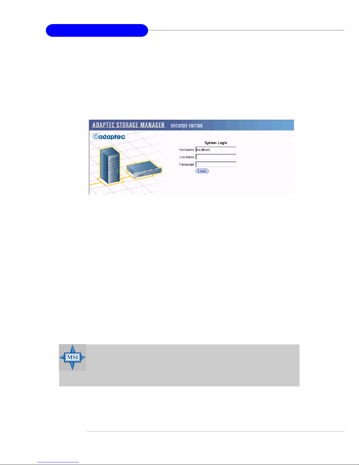
B-16
MS-9156 ATX Server Board
3. Logging In
T o login:
1. Start Adaptec Storage Manager – Browser Edition.
In W indows, click Start > Programs > Adaptec Storage Manager
> Adaptec Storage Manager – Browser Edition.
In Linux, click Start > System > Adaptec Storage Manager. The
Login screen appears.
2. Enter the host name or IP address of the system you want to manage and
the username and password you would use to log into that system.
3. Click Login.
Notes: When running Adaptec Storage Manager for the first time:
You need to install a security certificate if you chose not to during the
installation process. For instructions see Installing a Security
Certificate.
You are asked to register your software. For instructions see Register-
ing Your Software.
T o log in from any system with a Web browser:
1. Start the Web browser application and type the IP address for the system
you want to access in the address bar and press Enter. For example,
https://10.6.3.14:3513/adaptec. When connection to the remote system is established, the System Login screen appears.
2. Enter the host name or IP address of the system you want to manage and
the administrative username and password that you would normally
use to log into that system.
3. Click Login.
MSI Reminds Y ou...
If you are using a proxy server to access the Internet, you must
bypass the proxy server to access the Adaptec Storage Manager Web
server. See Configuring Internet Browsers on Windows for details.
Page 99

B-17
Adaptec SATA RAID Utility for Intel ICH-HR
4. Installing a Security Certificate
If you chose not to install a security certificate when you installed Adaptec
Storage Manager – Browser Edition, you must install the certificate when
you run the application for the first time.
T o create the certificate:
1. When the Security Alert window appears, click View Certificate.
2. On the Certificate window, click Install Certificate.
3. On the Certificate Import wizard window, click Next. The Certificate
Import wizard window’s contents change.
4. Accept the default, Automatically select the certificate store, and
click Next.
5. On the root Certificate Store window, click Yes. Another small Certifi-
cate Import wizard window appears.
6. Click OK. The Certificate window mentioned in Step 2 reappears.
7. Click OK . You are returned to the Security Alert window from Step 1.
8. Click Yes to finish the creation and storage of the certificate.
5. Registering Your Software
After installing and creating a security certificate, you are asked to register
the product. If you want click Register Now, your computer must have an
Internet connection. If you need to delay registration, click Register Later.
If you choose Register Later, you will be prompted to register the application the next time you run it.
Page 100

B-18
MS-9156 ATX Server Board
6. The Basics
An example of a typical Adaptec Storage Manager – Browser Edition screen
is shown below.
The action buttons are:
Logout—Selecting Logout ends your session and returns you to
the Login screen.
Rescan—Used to rescan the configuration of the system. Typically,
when a rescan is required, it occurs automatically , for example, after
an array is created.
However, the system configuration can change without Adaptec
Storage Manager being notified. For example, drives that are inserted or removed from a nonintelligent enclosure or an enclosure
powered on after you logged into Adaptec Storage Manager would
not be displayed unless you manually rescan.
The remaining buttons open additional windows that provide more detailed information and allow you to perform actions or change settings on a
specific aspect of your storage subsystem.
These are:
Events
Options
Help
Properties
Tasks
Immediately following the header frame is a controller information line including the model number of the first Adaptec RAID controller found in the
system and the amount of cache memory (if any) installed on that controller.
MSI Reminds Y ou...
Depending on your operating system, browser, and color scheme
you may notice some differences between this illustration and your
screen.
 Loading...