

Page 1
DKA790GX Platinum
Series
MS-7550 (V1.X) Mainboard
G52-75501X4
i
Page 2

Copyright Notice
The material in this document is the intellectual property of MICRO-STAR
INTERNATIONAL. We take every care in the preparation of this document, but no
guarantee is given as to the correctness of its contents. Our products are under
continual improvement and we reserve the right to make changes without notice.
Trademarks
All trademarks are the properties of their respective owners.
NVIDIA, the NVIDIA logo, DualNet, and nForce are registered trademarks or trade-
marks of NVIDIA Corporation in the United States and/or other countries.
AMD, Athlon™, Athlon™ XP, Thoroughbred™, and Duron™ are registered trade-
marks of AMD Corporation.
Intel® and Pentium® are registered trademarks of Intel Corporation.
PS/2 and OS®/2 are registered trademarks of International Business Machines
Corporation.
Windows® 2000/NT/XP/Vista are registered trademarks of Microsoft Corporation.
Netware® is a registered trademark of Novell, Inc.
Award® is a registered trademark of Phoenix Technologies Ltd.
AMI® is a registered trademark of American Megatrends Inc.
Revision History
Revision Revision History Date
V1.0 First release August 2008
Technical Support
If a problem arises with your system and no solution can be obtained from the user’s
manual, please contact your place of purchase or local distributor. Alternatively,
please try the following help resources for further guidance.
Visit the MSI website for FAQ, technical guide, BIOS updates, driver updates,
and other information: http://global.msi.com.tw/index.php?
func=service
Contact our technical staff at: http://ocss.msi.com.tw
ii
Page 3
Safety Instructions
1. Always read the safety instructions carefully.
2. Keep this User’s Manual for future reference.
3. Keep this equipment away from humidity.
4. Lay this equipment on a reliable flat surface before setting it up.
5. The openings on the enclosure are for air convection hence protects the equipment from overheating. DO NOT COVER THE OPENINGS.
6. Make sure the voltage of the power source and adjust properly 110/220V before connecting the equipment to the power inlet.
7. Place the power cord such a way that people can not step on it. Do not place
anything over the power cord.
8. Always Unplug the Power Cord before inserting any add-on card or module.
9. All cautions and warnings on the equipment should be noted.
10. Never pour any liquid into the opening that could damage or cause electrical
shock.
11. If any of the following situations arises, get the equipment checked by a service
personnel:
† The power cord or plug is damaged.
† Liquid has penetrated into the equipment.
† The equipment has been exposed to moisture.
† The equipment has not work well or you can not get it work according to
User’s Manual.
† The equipment has dropped and damaged.
† The equipment has obvious sign of breakage.
12. DO NOT LEAVE THIS EQUIPMENT IN AN ENVIRONMENT UNCONDITIONED, STORAGE TEMPERATURE ABOVE 600 C (1400F), IT MAY DAMAGE THE EQUIPMENT.
CAUTION: Danger of explosion if battery is incorrectly replaced.
Replace only with the same or equivalent type recommended by the
manufacturer.
iii
Page 4
FCC-B Radio Frequency Interference Statement
This equipment has been
tested and found to comply
with the limits for a Class B
digital device, pursuant to Part
15 of the FCC Rules. These limits are designed to provide reasonable protection
against harmful interference in a residential installation. This equipment generates,
uses and can radiate radio frequency energy and, if not installed and used in accor-
dance with the instructions, may cause harmful interference to radio communications.
However, there is no guarantee that interference will not occur in a particular
installation. If this equipment does cause harmful interference to radio or television
reception, which can be determined by turning the equipment off and on, the user is
encouraged to try to correct the interference by one or more of the measures listed
below.
† Reorient or relocate the receiving antenna.
† Increase the separation between the equipment and receiver.
† Connect the equipment into an outlet on a circuit different from that to
which the receiver is connected.
† Consult the dealer or an experienced radio/television technician for help.
Notice 1
The changes or modifications not expressly approved by the party responsible for
compliance could void the user’s authority to operate the equipment.
Notice 2
Shielded interface cables and A.C. power cord, if any, must be used in order to
comply with the emission limits.
VOIR LA NOTICE D ’INSTALLATION AVANT DE RACCORDER AU RESEAU.
Micro-Star International
MS-7550
This device complies with Part 15 of the FCC Rules. Operation is subject to the
following two conditions:
(1) this device may not cause harmful interference, and
(2) this device must accept any interference received, including interference that
may cause undesired operation.
iv
Page 5
WEEE (Waste Electrical and Electronic Equipment) Statement
v
Page 6

vi
Page 7
vii
Page 8

CONTENTS
Copyright Notice.........................................................................................................ii
Trademarks..................................................................................................................ii
Revision History.........................................................................................................ii
Technical Support......................................................................................................ii
Safety Instructions...................................................................................................iii
FCC-B Radio Frequency Interference Statement.............................................iv
WEEE (Waste Electrical and Electronic Equipment) Statement.......................v
English......................................................................................................................En-1
Specifications....................................................................................................En-2
Central Processing Unit: CPU...........................................................................En-5
Memory...............................................................................................................En-7
Connectors, Jumpers, Slots.............................................................................En-9
Back Panel........................................................................................................En-17
BIOS Setup.......................................................................................................En-20
Software Information......................................................................................En-28
Deutsch....................................................................................................................De-1
Spezifikationen..................................................................................................De-2
Hauptprozessor: CPU.......................................................................................De-5
Speicher.............................................................................................................De-7
Anschlüsse, Steckbrücken und Slots.............................................................De-9
Hinteres Anschlusspaneel.............................................................................De-17
BIOS Setup.......................................................................................................De-20
Software-Information......................................................................................De-28
Français.....................................................................................................................Fr-1
Spécificités.........................................................................................................Fr-2
Central Processing Unit: CPU............................................................................Fr-5
Mémoire...............................................................................................................Fr-7
Connecteurs, Cavaliers, Slots..........................................................................Fr-9
Panneau Arrière...............................................................................................Fr-17
Configuration du BIOS......................................................................................Fr-20
Information de Logiciel.....................................................................................Fr-28
Русский ....................................................................................................................Ru-1
Характеристики ...............................................................................................Ru-2
Центральный процессор (CPU).....................................................................Ru-5
Память ..............................................................................................................Ru-7
Коннекторы, перемычки, разъемы..............................................................Ru-9
Задняя панель ...............................................................................................Ru-17
Настройка BIOS..............................................................................................Ru-20
Сведения о программном обеспечении ...................................................Ru-28
viii
Page 9

DKA790GX
Platinum Series
User’s Guide
Engli sh
English
En-1
Page 10
MS-7550 Mainboard
Specifications
Processor Support
- Supports AM2+ Phenom FX/X4/X3/X2 processor
- Supports Athlon 64/FX/X2 processor
(For the latest information about CPU, please visit http://global.
msi.com.tw/index.php?func=cpuform)
HyperTransport
- Supports HyperTransport 3.0
Chipset
- North Bridge: AMD® 790GX chipset
- South Bridge: AMD® SB750 chipset
Memory Support
- DDR2 667/800/1066 SDRAM (8GB Max)
- 4 DDR2 DIMMs (240pin / 1.8V)
* (For more information on compatible components, please visit
http://global.msi.com.tw/index.php?func=testreport)
LAN
- Supports LAN 10/100/1000 Fast Ethermet by RTL8111C
IEEE 1394
- Chip integrated by Jmicron JMB381
- Transfer rate is up to 400Mb/s
- Supports 1 port
En-2
Audio
- HD Audio ALC888
- Up to 8-channel audio with jack sensing
IDE
- 1 IDE port by SB750
- Supports Ultra DMA 66/100/133 mode
- Supports PIO, Bus Master operation mode
SATA
- SATA II ports by SB750
- Supports 5 SATA II devices
- Supports storage and data transfers at up to 3.0 Gb/s
eSATA
- Supports 1 e-SATA port by SB750
- Supports storage and data transfers at up to 3.0 Gb/s
RAID
- SATA1~5 supports RAID 0/ 1/ 0+1/ 5 or JBOD mode by SB750
Page 11
Floppy
- 1 floppy port
- Supports 1 FDD with 360KB, 720KB, 1.2MB, 1.44MB and 2.88MB
Connectors
Back panel
- 1 PS/2 mouse or keyboard port
- 1 IEEE 1394 port
- 6 USB 2.0 Ports
- 1 LAN jack
- 6 flexible audio jacks
- 1 Optical SPDIF out jack
- 1 e-SATA port
- 1 DVI-D port
- 1 VGA port
- 1 HDMI port
On-Board Pinheaders/ Connectors
- 3 USB 2.0 pinheaders
- 1 COM port pinheader
- 1 CD-in pinheader
- 1 TPM Module pinheader
- 1 Chassis Intrusion
- 1 Front Panel Audio pinheader
- 1 Wake on LAN connector
Slots
- 2 PCI Express x16 slots
(support into two x 8 ports when Gross-Fire Enabled)
- 2 PCI Express x1 slots
- 2 PCI slots
Form Factor
- ATX (30.4cm X 24.5 cm)
Engli sh
Mounting
- 9 mounting holes
En-3
Page 12
MS-7550 Mainboard
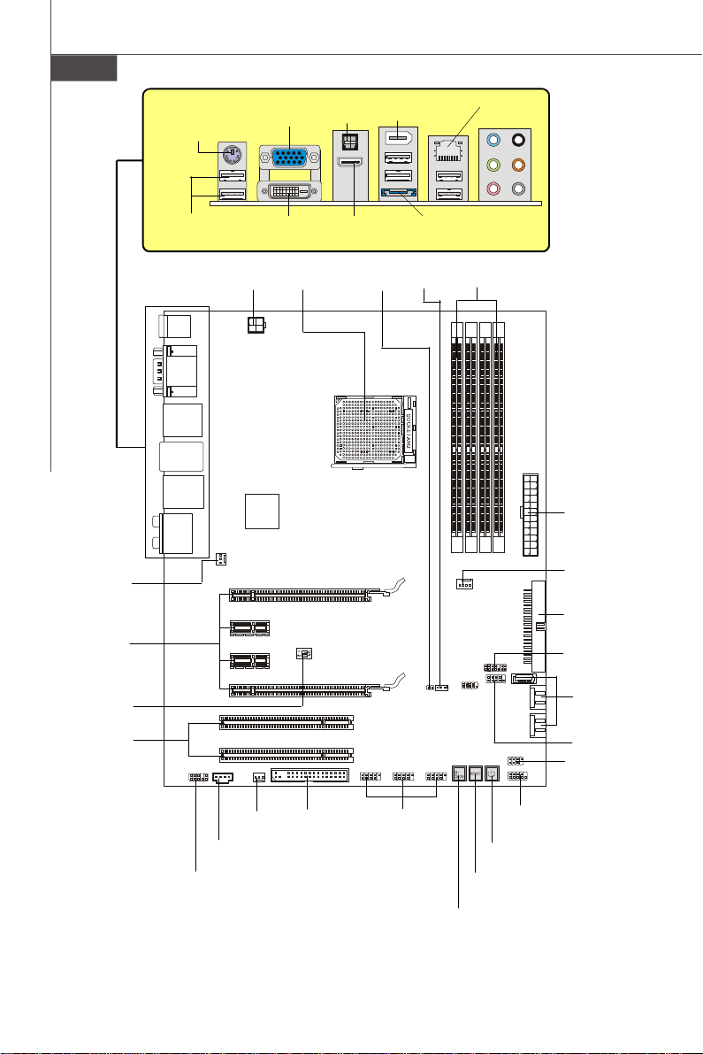
Mouse/
Keyboard,
p.En-17
USB ports,
p.En-18
DVI-D Port,
p.En-17
JPWR2,
p.En-15
VGA Port,
p.En-17
CPU,
p.En-5
SPDIF out,
p.En-17
HDMI Port,
p.En-18
JCI1,
p.En-11
1394 port,
p.En-18
eSATA port,
p.En-18
WOL1,
p.En-12
LAN,
p.En-19
RS-Out
L-In
L-Out
CS-Out
Mic
SS-Out
Audio Port,
p.En-19
DDR2,
p.En-7
JPWR1,
p.En-15
SYS_FAN1,
p.En-9
PCI_E,
p.En-16
U117,
p.En-13
PCI,
p.En-16
JUSB1~3,
p.En-11
POWER1,
p.En-13
RESET1,
p.En-13
CLR_CMOS1,
p.En-14
JCD1,
p.En-10
JAUD1,
p.En-12
SYS_FAN2,
p.En-9
FDD1,
p.En-9
Quick Components Guide of DKA790GX Platinum Series
En-4
(MS-7550 v1.X) Mainboard
CPU_FAN1,
p.En-9
IDE1,
p.En-9
JTPM,
p.En-12
SATA1~5,
p.En-10
JCOM1,
p.En-11
JFP2,
p.En-10
JFP1,
p.En-10
Page 13
Central Processing Unit: CPU
Correct CPU
The mainboard supports AMD® processor. The mainboard uses a CPU socket called
Socket AM2/AM2+ for easy CPU installation. If you do not have the CPU cooler, consult
your dealer before turning on the computer.
For the latest information about CPU, please visit http://global.msi.com.tw/index.php?
func=cpuform
Important
Overheating
Overheating will seriously damage the CPU and system. Always make sure the
cooling fan can work properly to protect the CPU from overheating. Make sure
that you apply an even layer of thermal paste (or thermal tape) between the CPU
and the heatsink to enhance heat dissipation.
Replaceing the CPU
While replacing the CPU, always turn off the ATX power supply or unplug the
power supply’s power cord from the grounded outlet first to ensure the safety of
CPU.
Overclocking
This mainboard is designed to support overclocking. However, please make
sure your components are able to tolerate such abnormal setting, while doing
overclocking. Any attempt to operate beyond product specifications is not
recommended. We do not guarantee the damages or risks caused by inad-
equate operation or beyond product specifications.
CPU Installation Procedures for Socket AM2/ AM2+
1.Please turn off the power and unplug the power cord before installing the CPU.
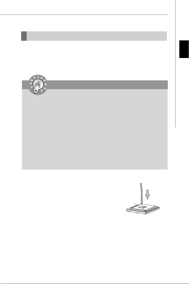
2.Pull the lever sideways away from the socket. Make sure to
raise the lever up to a 90-degree angle.
3.Look for the gold arrow of the CPU. The gold arrow should
Gold arrow
point as shown in the picture. The CPU can only fit in the
correct orientation.
4.If the CPU is correctly installed, the pins should be completely embedded into the socket and can not be seen. Please note that any
violation of the correct installation procedures may cause permanent damages to
your mainboard.
5.Press the CPU down firmly into the socket and close the lever. As the CPU is likely to
move while the lever is being closed, always close the lever with your fingers pressing tightly on top of the CPU to make sure the CPU is properly and completely
embedded into the socket.
placement
Engli sh
En-5
Page 14
MS-7550 Mainboard
Installing CPU Cooler Set
When you are installing the CPU, make sure the CPU has a heat sink and a cooling
fan attached on the top to prevent overheating. If you do not have the CPU cooler,
consult your dealer before turning on the computer.
Important
Mainboard photos shown in this section are for demonstration of the CPU/ cooler
installation only. The appearance of your mainboard may vary depending on the
model you purchase.
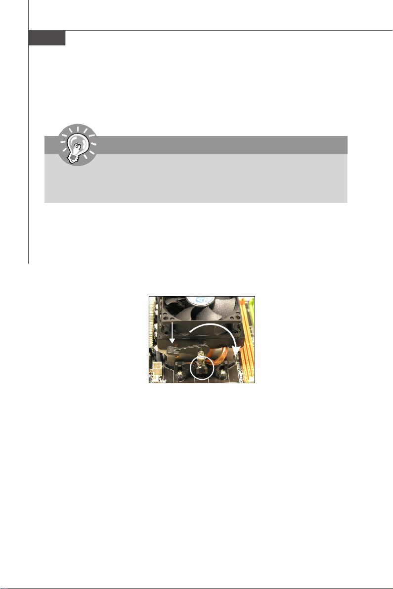
1.Position the cooling set onto the retention mechanism. Hook one end of the clip to
hook first.
2.Then press down the other end of the clip to fasten the cooling set on the top of the
retention mechanism. Locate the Fix Lever and lift up it .
3.Fasten down the lever.
4.Attach the CPU Fan cable to the CPU fan connector on the mainboard.
Fixed Lever
En-6
Page 15
Memory
1
2
3
Installed
These DIMM slots are used for installing memory modules.
For more information on compatible components, please visit http://global.msi.com.tw/
index.php?func=testreport
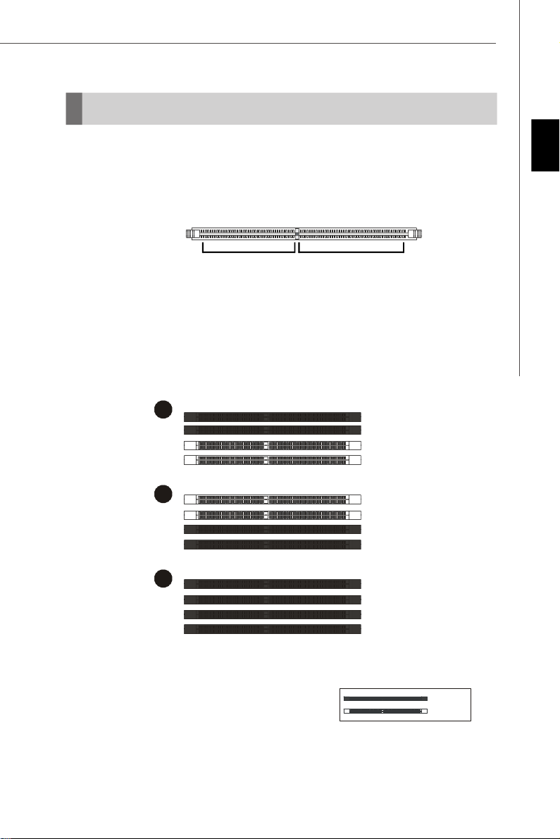
DDR2
240-pin, 1.8V
64x2=128 pin56x2=112 pin
Dual-Channel Memory Population Rules
In Dual-Channel mode, the memory modules can transmit and receive data with two
data bus lines simultaneously. Enabling Dual-Channel mode can enhance the
system performance. Please refer to the following illustrations for population rules
under Dual-Channel mode.
DIMM1
DIMM2
DIMM3
DIMM4
DIMM1
DIMM2
DIMM3
DIMM4
Engli sh
DIMM1
DIMM2
DIMM3
DIMM4
Empty
En-7
Page 16
MS-7550 Mainboard
Installing Memory Modules
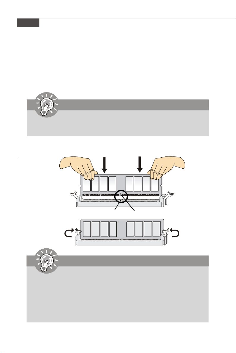
1. The memory module has only one notch on the center and will only fit in the right
orientation.
2. Insert the memory module vertically into the DIMM slot. Then push it in until the
golden finger on the memory module is deeply inserted in the DIMM slot. The plastic
clip at each side of the DIMM slot will automatically close when the memory module
is properly seated.
Important
You can barely see the golden finger if the memory module is properly inserted in
the DIMM slot.
3. Manually check if the memory module has been locked in place by the DIMM slot
clips at the sides.
Volt
Notch
Important
-DDR2 memory modules are not interchangeable with DDR and the DDR2
standard is not backwards compatible. You should always install DDR2
memory modules in the DDR2 DIMM slots.
-In Dual-Channel mode, make sure that you install memory modules of the
same type and density in different channel DIMM slots.
-To enable successful system boot-up, always insert the memory modules
into the DIMM1 first.
En-8
Page 17
Connectors, Switchs, Buttons, Slots
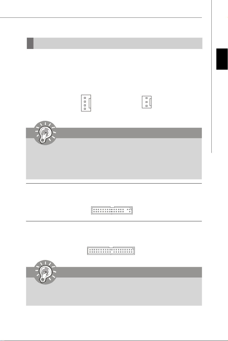
Fan Power Connectors: CPU_FAN1, SYS_FAN1/2
The fan power connectors support system cooling fan with +12V. The CPU FAN supports
Smart FAN function. When connect the wire to the connectors, always take note that the
red wire is the positive and should be connected to the +12V, the black wire is Ground
and should be connected to GND. If the mainboard has a System Hardware Monitor
chipset on-board, you must use a specially designed fan with speed sensor to take
advantage of the fan control.
Engli sh
Control
SENSOR
+12V
GND
CPU_FAN1
SENSOR or NC
+12V
GND
SYS_FAN1/2
Important
1.Please refer to the recommended CPU fans at processor’s official website or
consult the vendors for proper CPU cooling fan.
2.CPUFAN supports fan control. You can install Dual Core Center utility that
will automatically control the CPU fan speed according to the actual CPU
temperature.
3. Fan cooler set with 3 or 4 pins power connector are both available for CPUFAN.
Floppy Disk Drive Connector: FDD1
This connector supports 360KB, 720KB, 1.2MB, 1.44MB or 2.88MB floppy disk drive.
IDE connector: IDE1
This connector supports IDE hard disk drives, optical disk drives and other IDE devices.
Important
If you install two IDE devices on the same cable, you must configure the drives
separately to Master/ Slave mode by setting jumpers. Refer to IDE device’s docu-
mentation supplied by the vendors for jumper setting instructions.
En-9
Page 18
MS-7550 Mainboard
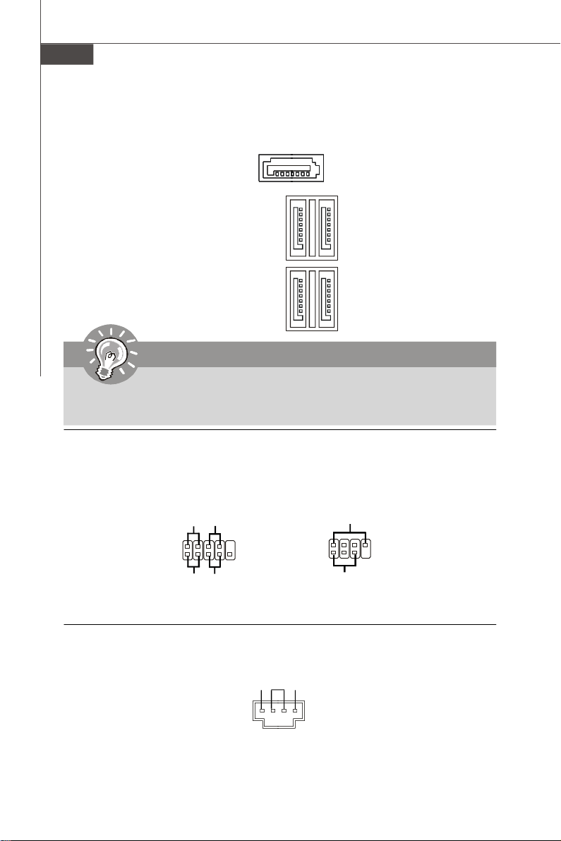
Serial ATA Connector: SATA1~5
This connector is a high-speed Serial ATA interface port. Each connector can connect to
one Serial ATA device.
SATA5
SATA1-2
SATA3-4
Important
Please do not fold the Serial ATA cable into 90-degree angle. Otherwise, data
loss may occur during transmission.
Front Panel Connectors: JFP1, JFP2
These connectors are for electrical connection to the front panel switches and LEDs.
The JFP1 is compliant with Intel® Front Panel I/O Connectivity Design Guide.
Power
Power
LED
Switch
-
+
JFP1
2
1
+
HDD
LED
- -
+
Reset
Switch
10
9
JFP2
CD-In Connector: JCD1
This connector is provided for external audio input.
GND R
L
En-10
2
1
Speaker
+
Power
LED
+
-
8
7
Page 19
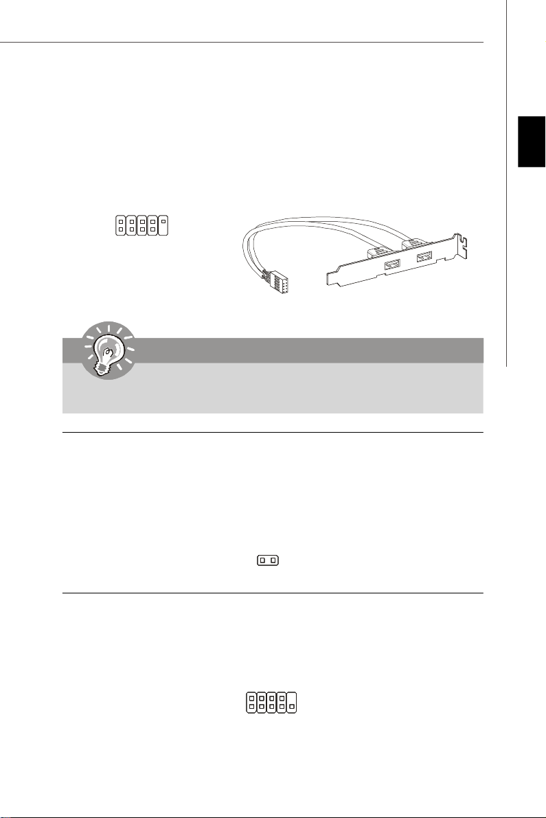
Front USB Connector (Yellow): JUSB1~3
This connector, compliant with Intel® I/O Connectivity Design Guide, is ideal for connecting high-speed USB interface peripherals such as USB HDD, digital cameras, MP3
players, printers, modems and the like.
USB 2.0 Bracket
(Optional)
2
1
VCC
VCC
USBOC
USB1-
USB1+
GND
10
9
GND
USB0-
USB0+
Key (no pin)
Important
Note that the pins of VCC and GND must be connected correctly to avoid possible
damage.
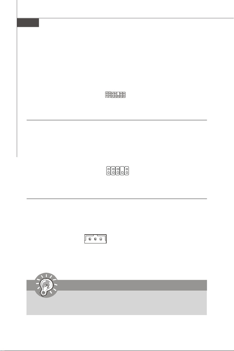
Chassis Intrusion Connector: JCI1
This connector connects to the chassis intrusion switch cable. If the chassis is opened,
the chassis intrusion mechanism will be activated. The system will record this status and
show a warning message on the screen. To clear the warning, you must enter the BIOS
utility and clear the record.
English
GN D
C INT RU
2
1
Serial Port Connector: JCOM1
This connector is a 16550A high speed communication port that sends/receives 16
bytes FIFOs. You can attach a serial device.
SIN
CTS
DSR
2
1
DCD
10
9
RI
RTS
SOUT DTR
Ground
En-11
Page 20
MS-7550 Mainboard
TPM module Connector: JTPM(optional)
This connector connects to a TPM (Trusted Platform Module) module (optional). Please
refer to the TPM security platform manual for more details and usages.
3V dua l / 3V _ST B
VC C3
SIR Q
VC C5
Ke y(n o pin )
GN D
GN D
2
1
14
13
LCLK
LAD0
LAD1
LAD2
LAD3
LR ST#
LF RA ME #
Front Panel Audio Connector (Azalia Spec): JAUD1
This connector allows you to connect the front panel audio and is compliant with Intel
Front Panel I/O Connectivity Design Guide.
M IC_ J D
NC (N o pi n)
Gr oun d
Pr esen ce#
2
1
MI C _ L
LI NE ou t_ JD
10
9
M IC _R
Fr on t_J D
LIN E ou t_L
LI NE ou t_ R
Wake-Up on LAN Connector: WOL1
This connector is for use with LAN add-on cards that supports Wake Up on LAN function.
To use this function, you need to set the “Wake-Up on LAN” to enable at the BIOS.
Note: LAN wake-up signal is
active “high”.
GND
5VSB
MP_WAKEUP
Important
®
To be able to use this function, you need a power supply that provide enough
power for this feature. (Power supply with 750ma 5V Stand-by)
En-12
Page 21
Overclock FSB Switch: U117 (optional)
1
2
O
N
You can overclock the FSB to increase the processor frequency by changing the switch.
Follow the instructions below to set the FSB.
DOC1 DOC2 CPU Frequency
1:ON 2:ON Default
1:ON 2:OFF Increase 10% speed of FSB
1:OFF 2:ON Increase 15% speed of FSB
1:OFF 2:OFF Increase 20% speed of FSB
Important
1.Make sure that you power off the system before setting the switch.
2.When hardware overclocking cause system instability or crash during
boot, the following warning message will display during POST. And then,
please set the switch to default setting.
Warning!!! OC switch overclocking had failed,
Please shutdown and adjust oc switch to lower frequency.
Try again!
English
Power Button: POWER1
This power button is used to turn-on or turn-off the system. Press the button to turn-on or
turn-off the system.
Reset Button: RESET1
This reset button is used to reset the system. Press the button to reset the system.
En-13
Page 22
MS-7550 Mainboard
Clear CMOS Button: CLR_CMOS1
There is a CMOS RAM on board that has a power supply from external battery to keep
the system configuration data. With the CMOS RAM, the system can automatically boot
OS every time it is turned on. If you want to clear the system configuration, use the
button to clear data. Press the button to clear the data.
Important
Make sure that you power off the system before clearing CMOS data.
En-14
Page 23
Power Supply Attachment
Before inserting the power supply connector, always make sure that all components are
installed properly to ensure that no damage will be caused. All power connectors on
the mainbnoard have to connect to the ATX power supply and have to work together to
ensure stable operation of the mainboard.
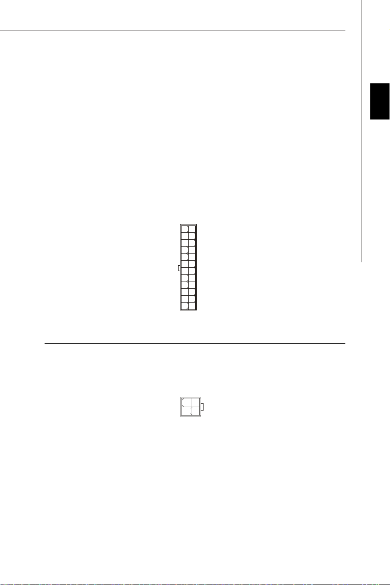
ATX 24-Pin Power Connector: JPWR1
This connector allows you to connect an ATX 24-pin power supply. To connect the ATX
24-pin power supply, make sure the plug of the power supply is inserted in the proper
orientation and the pins are aligned. Then push down the power supply firmly into the
connector.
You may use the 20-pin ATX power supply as you like. If you’d like to use the 20-pin ATX
power supply, please plug your power supply along with pin 1 & pin 13.
13
1
NC
1224
+3.3V
+3.3V
GND
+5V
GND
+5V
GND
PWR OK
5VSB
+12V
+12V
+3.3VGND
+3.3V
-12V
GND
PS-ON#
GND
GND
GND
+5V
+5V
+5V
ATX 12V Power Connector (2x2-Pin): JPWR2
This 12V power connector is used to provide power to the CPU.
English
GND
GND
1 3
2
12V
12V
4
En-15
Page 24

MS-7550 Mainboard
PCI Express Slot (x16/ x1)
The PCI Express slot supports the PCI Express interface expansion card.
PCI Express x16 Slot
PCI Express x 1 Slot
PCI (Peripheral Component Interconnect) Slot
The PCI slot supports LAN card, SCSI card, USB card, and other add-on cards that
comply with PCI specifications.
Important
When adding or removing expansion cards, make sure that you unplug the power
supply first. Meanwhile, read the documentation for the expansion card to configure
any necessary hardware or software settings for the expansion card, such as
jumpers, switches or BIOS configuration.
En-16
Page 25
Back Panel
Mouse/Keyboard
The standard PS/2® mouse/keyboard DIN connector is for a PS/2® mouse/keyboard.
VGA Port
The DB15-pin female connector is provided for monitor.
15
(15-Pin Female DIN Connector)
1115
DVI-D Port
The DVI-D (Digital Visual Interface) connector allows you to connect an LCD monitor. It
provides a high-speed digital interconnection between the computer and its display
device. To connect an LCD monitor, simply plug your monitor cable into the DVI
connector, and make sure that the other end of the cable is properly connected to your
monitor (refer to your monitor manual for more information.)
8
1
English
17
24
Important
Please note that the DVI-D connector does not support connecting the D-Sub to
DVI-D converter.
Optical S/PDIF-out
This S/PDIF (Sony & Philips Digital Interconnect Format) connector is provided for
digital audio transmission to external speakers through an optical fiber cable.
En-17
Page 26
MS-7550 Mainboard
HDMI Port
The High-Definition Multimedia Interface (HDMI) is an all-digital audio/video interface
capable of transmitting uncompressed streams. HDMI supports all TV format, including
standard, enhanced, or high-definition video, plus multi-channel digital audio on a
single cable.
1394 Port
The IEEE1394 port on the back panel provides connection to IEEE1394 devices.
USB Port
The USB (Universal Serial Bus) port is for attaching USB devices such as keyboard,
mouse, or other USB-compatible devices.
External SATA Port
This eSATA (External Serial ATA) port is used to connect the external SATA device. You
can also use the optional external SATA cable to connect SATA device and eSATA port.
En-18
Page 27
LAN
The standard RJ-45 LAN jack is for connection to the Local Area Network (LAN). You can
connect a network cable to it.
LED Color LED State Condition
Off LAN link is not established.
Left Orange On (steady state) LAN link is established.
On (brighter & pulsing) The computer is communicating with another computer on the LAN.
Green Off 10 Mbit/sec data rate is selected.
Right On 100 Mbit/sec data rate is selected.
Orange On 1000 Mbit/sec data rate is selected.
Audio Port Connectors
These audio connectors are used for audio devices. You can differentiate the color of
the audio jacks for different audio sound effects.
English
Line-In (Blue) - Line In, is used for external CD player, tape player or other audio
devices.
Line-Out (Green) - Line Out, is a connector for speakers or headphones.
MIC (Pink) - Mic In, is a connector for microphones.
RS-Out (Black) - Rear-Surround Out in 4/ 5.1/ 7.1 channel mode.
CS-Out (Orange) - Center/ Subwoofer Out in 5.1/ 7.1 channel mode.
SS-Out (Gray) - Side-Surround Out 7.1 channel mode.
En-19
Page 28
MS-7550 Mainboard
BIOS Setup
This chapter provides basic information on the BIOS Setup program and allows you to
configure the system for optimum use. You may need to run the Setup program when:
* An error message appears on the screen during the system booting up, and requests
you to run BIOS SETUP.
* You want to change the default settings for customized features.
Important
1.The items under each BIOS category described in this chapter are under continuous update for better system performance. Therefore, the description may
be slightly different from the latest BIOS and should be held for reference only.
2.Upon boot-up, the 1st line appearing after the memory count is the BIOS
version. It is usually in the format:
A7550AMS V1.0 010108 where:
1st digit refers to BIOS maker as A = AMI, W = AWARD, and P = PHOENIX.
2nd - 5th digit refers to the model number.
6th refers to the Chipset vender as A = AMD, I = Intel, V = VIA, N = Nvidia,
7th - 8th digit refers to the customer as MS = all standard customers.
V1.0 refers to the BIOS version.
010108 refers to the date this BIOS was released.
En-20
Page 29
Entering Setup
Power on the computer and the system will start POST (Power On Self Test) process.
When the message below appears on the screen, press <DEL> key to enter Setup.
Press DEL to enter SETUP
If the message disappears before you respond and you still wish to enter Setup, restart
the system by turning it OFF and On or pressing the RESET button. You may also restart
the system by simultaneously pressing <Ctrl>, <Alt>, and <Delete> keys.
Getting Help
After entering the Setup menu, the first menu you will see is the Main Menu.
Main Menu
The main menu lists the setup functions you can make changes to. You can use the
arrow keys (↑↓ ) to select the item. The on-line description of the highlighted setup
function is displayed at the bottom of the screen.
Sub-Menu
If you find a right pointer symbol (as shown in the right view)
appears to the left of certain fields that means a sub-menu
containing additional options can be launched from this
field. You can use control keys (↑↓ ) to highlight the field
and press <Enter> to call up the sub-menu. Then you can
use the control keys to enter values and move from field to field within a sub-menu. If
you want to return to the main menu, just press <Esc >.
General Help <F1>
The BIOS setup program provides a General Help screen. You can call up this screen
from any menu by simply pressing <F1>. The Help screen lists the appropriate keys to
use and the possible selections for the highlighted item. Press <Esc> to exit the Help
screen.
English
En-21
Page 30
MS-7550 Mainboard
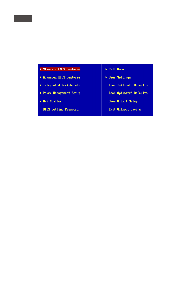
The Main Menu
Once you enter AMI® or AWARD® BIOS CMOS Setup Utility, the Main Menu will appear
on the screen. The Main Menu allows you to select from ten setup functions and two exit
choices. Use arrow keys to select among the items and press <Enter> to accept or enter
the sub-menu.
Standard CMOS Features
Use this menu for basic system configurations, such as time, date etc.
Advanced BIOS Features
Use this menu to setup the items of special enhanced features.
Integrated Peripherals
Use this menu to specify your settings for integrated peripherals.
Power Management Setup
Use this menu to specify your settings for power management.
H/W Monitor
This entry shows your PC health status.
BIOS Setting Password
Use this menu to set the password for BIOS.
Cell Menu
Use this menu to specify your settings for fequency/voltage control and overclocking.
User Settings
Use this menu to save/ load your settings to/ from CMOS for BIOS.
Load Fail-Safe Defaults
Use this menu to load the default values set by the BIOS vendor for stable system
performance.
Load Optimized Defaults
Use this menu to load the default values set by the mainboard manufacturer specifically
for optimal performance of themainboard.
Save & Exit Setup
Save changes to CMOS and exit setup.
Exit Without Saving
Abandon all changes and exit setup.
En-22
Page 31

When enter the BIOS Setup utility, follow the processes below for general use.
1. Load Optimized Defaults : Use control keys (↑↓ ) to highlight the Load Optimized
Defaults field and press <Enter> , a message as below appears:
Press [Ok] to load the default settings for optimal system performance.
2. Setup Date/ Time : Select the Standard CMOS Features and press <Enter> to enter
the Standard CMOS Features-menu. Adjust the Date, Time fields.
3. Save & Exit Setup : Use control keys (↑↓ ) to highlight the Save & Exit Setup field
and press <Enter> , a message as below appears:
English
Press [Ok] to save the configurations and exit BIOS Setup utility.
Important
The configuration above are for general use only. If you need the detailed
settings of BIOS, please see the manual in English version on MSI website.
En-23
Page 32

MS-7550 Mainboard
4. Cell Menu Introduction : This menu is for advanced user who want to overclock the
mainboard.
Important
Change these settings only if you are familiar with the chipset.
Current CPU / DRAM Frequency
These items show the current clocks of CPU and Memory speed. Read-only.
AMD Cool’n’Quiet
The Cool’ n’ Quiet technology can effectively and dynamically lower CPU speed and
power consumption.
En-24
Page 33

Important
To ensure that Cool’n’Quiet function is activated and will be working properly, it is
required to double confirm that:
1.Run BIOS Setup, and select Cell Menu.
Under Cell Menu, find AMD Cool’n’Quiet,
and set this item to “Enable.”
2.Enter Windows, and select [Start]->
[Settings]->[Control Pannel]->[Power
Options]. Enter Power Options Proper-
ties tag, and select Minimal Power Management under Power schemes.
Adjust CPU FSB Frequency (MHz)
This item allows you to adjust the CPU FSB frequency.
Adjust CPU Ratio
This item lets you to adjust the CPU ratio. It is available only when the processor
supports this function.
Adjust CPU-NB Ratio (for AM2+ CPU only)
This item lets you to adjust the NB ratio of the CPU. It is available only when the
processor supports this function.
Adjusted CPU Frequency (MHz)
It shows the adjusted CPU frequency (FSB x Ratio). Read-only.
English
Advanced Clock Calibration (for AM2+ CPU only)
This item is for overclock. Setting to [Enabled] allows you to set the CPU Ratio higher.
Onboard VGA Core Overclock
This item is used to enable/ disable the onboard VGA core overclock.
Advance DRAM Configuration
Press <Enter> to enter the sub-menu.
MEMORY-Z
Press <Enter> to enter the sub-menu.
DIMM1/2/3/4 Memory SPD Information
Press <Enter> to enter the sub-menu.
E.P.P SUPPORT Information
Press <Enter> to enter the sub-menu.
En-25
Page 34

MS-7550 Mainboard
DRAM Timing Mode
Setting to [Auto] enables DRAM CAS# Latency automatically to be determined
by BIOS based on the configurations on the SPD (Serial Presence Detect)
EEPROM on the DRAM module.
1T/2T Memory Timing
This field controls the SDRAM command rate. Selecting [1T] makes SDRAM
signal controller to run at 1T (T=clock cycles) rate. Selecting [2T] makes SDRAM
signal controller run at 2T rate.
Bank Interleaving
This field selects 2-bank or 4-bank interleave for the installed SDRAM. Disable the
function if 16MB SDRAM is installed.
DCT Unganged Mode
This is used to enable/ disable the DCT Unganged Mode (for Phenom only).
EPP Technology Support
This is used to enable/ disable the EPP technology.
FSB/DRAM Ratio
This item will allow you to adjust the ratio of FSB to memory.
Adjusted DRAM Frequency (MHz)
It shows the adjusted DRAM frequency. Read-only.
HT Link Speed
This item allows you to set the Hyper-Transport Link speed. Setting to [Auto], the
system will detect the HT link speed automatically.
Adjust PCI-E Frequency (MHz)
This field allows you to select the PCIE frequency (in MHz).
Auto Disable PCI Frequency
When set to [Enabled], the system will remove (turn off) clocks from empty PCI slots to
minimize the electromagnetic interference (EMI).
CPU VDD Voltage (V) / CPU-NB VDD Voltage (V)/ CPU Voltage (V) / CPU-NB
Voltage (V)/ DRAM Voltage (V)/ NB Voltage (V)/ HT Link Voltage (V)/ MCT Voltage (V)
These items are used to adjust the voltage of CPU, Memory, FSB and chipset.
Spread Spectrum
When the motherboard’s clock generator pulses, the extreme values (spikes) of the
pulses create EMI (Electromagnetic Interference). The Spread Spectrum function
reduces the EMI generated by modulating the pulses so that the spikes of the pulses
are reduced to flatter curves. If you do not have any EMI problem, leave the setting
at Disabled for optimal system stability and performance. But if you are plagued by
EMI, set to Enabled for EMI reduction. Remember to disable Spread Spectrum if you
are overclocking because even a slight jitter can introduce a temporary boost in clock
speed which may just cause your overclocked processor to lock up.
En-26
Page 35

Important
1.If you do not have any EMI problem, leave the setting at [Disabled] for optimal
system stability and performance. But if you are plagued by EMI, select the
value of Spread Spectrum for EMI reduction.
2.The greater the Spread Spectrum value is, the greater the EMI is reduced,
and the system will become less stable. For the most suitable Spread Spectrum value, please consult your local EMI regulation.
3.Remember to disable Spread Spectrum if you are overclocking because even
a slight jitter can introduce a temporary boost in clock speed which may just
cause your overclocked processor to lock up.
English
En-27
Page 36

MS-7550 Mainboard
Software Information
Take out the Driver/Utility CD that is included in the mainboard package, and place it
into the CD-ROM driver. The installation will auto-run, simply click the driver or utiltiy
and follow the pop-up screen to complete the installation. The Driver/Utility CD contains the:
Driver menu - The Driver menu shows the available drivers. Install the driver by your
desire and to activate the device.
Utility menu - The Utility menu shows the software applications that the mainboard
supports.
WebSite menu- The WebSite menu shows the necessary websites.
Important
Please visit the MSI website to get the latest drivers and BIOS for better system
performance.
En-28
Page 37

DKA790GX
Platinum Series
Benutzerhandbuch
Deutsch
Deutsch
De-1
Page 38

MS-7550 Mainboard
Spezifikationen
Prozessoren
- Unterstützt AM2+ Phenom FX/X4/X3/X2 Prozessor
- Unterstütz Athlon 64/FX/X2 Prozessor
(Weitere CPU Informationen finden Sie unter http://global.msi.
com.tw/index.php?func=cpuform)
HyperTransport
- Unterstützt HyperTransport 3.0
Chipsatz
- North-Bridge: AMD® 790GX Chipsatz
- South-Bridge: AMD® SB750 Chipsatz
Speicher
- DDR2 667/800/1066 SDRAM (max. 8GB)
- 4 DDR2 DIMMs (240Pin / 1.8V)
* (Weitere Informationen zu kompatiblen Speichermodulen finden
Sie unter http://global.msi.com.tw/index.php?func=testreport)
LAN
- Unterstützt LAN 10/100/1000 Fast Ethermet über RTL8111C
IEEE 1394
- Onboard Chip über Jmicron JMB381
- Übertragungsgeschwindigkeit von bis zu 400Mb/s
- Unterstützt 1 Port
De-2
Audio
- HD Audio ALC888
- 8-Kanal Audio-Ausgang mit “Jack Sensing” Funktion
IDE
- 1 IDE Port über SB750
- Unterstützt die Betriebmodi mit Ultra DMA 66/100/133
- Unterstützt die Betriebmodi mit PIO, Bus Mastering
SATA
- SATA II Ports über SB750
- Unterstützt fünf SATA II Geräte
- Unterstützt Datenübertragungsraten von bis zu 3.0 Gb/s
eSATA
- Unterstützt 1 e-SATA port by SB750
- Unterstützt Datenübertragungsraten von bis zu 3.0 Gb/s
RAID
- SATA1~5 unterstützt die Modi RAID 0/ 1/ 0+1/ 5 oder JBOD über
SB750
Page 39

Diskette
- 1 Disketten Anschluss
- Unterstützt 1 FDD mit 360KB, 720KB, 1.2MB, 1.44MB und 2.
88MB
Anschlüsse
Hintere Ein-/ und Ausgänge
- 1 PS/2 Maus- oder Tastaturanschluss
- 1 IEEE 1394 Anschluss
- 6 USB 2.0 Anschlüsse
- 1 LAN Anschluss
- 6 Audiobuchsen
- 1 Optical SPDIF-Ausgang Anschluss
- 1 e-SATA Anschluss
- 1 DVI-D Anschluss
- 1 VGA Anschluss
- 1 HDMI Anschluss
On-Board Stiftleiste/ Anschlüsse
- 3 USB 2.0 Stiftleisten
- 1 COM Stiftleiste
- 1 CD-Stiftleiste für Audio Eingang
- 1 TPM Modul Schnittstelle
- 1 Gehäusekontaktschalter
- 1 Audio Stiftleiste für Gehäuse Audio Ein-/ Ausgänge
- 1 Wake-on-LAN Schnittstelle
Schnittstellen
- 2 PCI Express x16 Schnittstellen
(Unterstützt zwei x 8 Anschlüsse, wenn Gross-Fire aktiviert ist.)
- 2 PCI Express x1 Schnittstellen
- 2 PCI Schnittstellen
Deutsch
Form Faktor
- ATX (30.4cm X 24.5 cm)
Montage
- 9 Montagebohrungen
De-3
Page 40

MS-7550 Mainboard
Maus/
Tastatur,
S.De-17
USB ports,
S.De-18
DVI-D Port,
S.De-17
JPWR2,
S.De-15
VGA Port,
S.De-17
CPU,
S.De-5
SPDIF out,
S.De-17
HDMI Port,
S.De-18
JCI1,
S.De-11
1394 port,
S.De-18
eSATA port,
S.De-18
WOL1,
S.De-12
LAN,
S.De-19
RS-Out
L-In
L-Out
CS-Out
Mic
SS-Out
Audio Port,
S.De-19
DDR2,
S.De-7
JPWR1,
S.De-15
SYS_FAN1,
S.De-13
PCI_E,
S.De-16
U117,
S.V-13
PCI,
S.De-16
De-4
JFP1,
S.De-10
POWER1,
S.De-13
RESET1,
S.De-13
JCD1,
S.De-10
JAUD1,
S.De-12
SYS_FAN2,
S.De-9
FDD1,
S.De-9
JUSB1~3,
S.De-11
CLR_CMOS1,
S.De-14
Übersicht Eingenschaften der DKA790GX Platinum
Mainboard Serie (MS-7550 v1.X)
CPU_FAN1,
S.De-9
IDE1,
S.De-9
JTPM,
S.De-12
SATA1~5,
S.De-10
JCOM1,
S.De-11
JFP2,
S.De-10
Page 41

Correct CPU
Hauptprozessor: CPU
Das Mainboard unterstützt Intel® Prozessoren und verwendet hierfür einen CPU Sockel
mit der Bezeichnung Sockel-775, um das Einsetzen der CPU zu erleichtern. Verfügen
Sie über keinen Kühler, setzen Sie sich bitte mit Ihrem Händler in Verbindung, um
einen solchen zu erwerben und danach zu installieren, bevor Sie Ihren Computer
anschalten.
Um die neuesten Informationen zu unterstützten Prozessoren zu erhalten, besuchen
Sie bitte http://global.msi.com.tw/index.php?func=cpuform
Wichtig
Überhitzung
Überhitzung beschädigt die CPU und das System nachhaltig, stellen Sie stets
eine korrekte Funktionsweise des CPU Kühlers sicher, um die CPU vor
Überhitzung zu schützen. Überprüfen Sie eine gleichmäßige Schicht der
thermischen Paste (oder thermischen Klebeandes) zwischen der CPU und dem
Kühlblech anwenden, um Wärmeableitung zu erhöhen.
CPU Wechsel
Stellen Sie vor einem Wechsel des Prozessors stets sicher, dass das ATX
Netzteil ausgeschaltet und der Netzstecker gezogen ist, um die Unversehrtheit
der CPU zu gewährleisten.
Übertakten
Dieses Motherboard wurde so entworfen, dass es Übertakten unterstützt. Stellen
Sie jedoch bitte sicher, dass die betroffenen Komponenten mit den abweichenden
Einstellungen während des Übertaktens zurecht kommen. Von jedem Versuch des
Betriebes außerhalb der Produktspezifikationen kann nur abgeraten werden. Wir
übernehmen keinerlei Garantie für die Schäden und Risiken, die aus
unzulässigem oder Betrieb jenseits der Produktspezifikationen resultieren.
Deutsch
Vorgehensweise CPU Einbau beim Sockel AM2
1.Bitte Schalten Sie das System aus und ziehen Sie den
Netzstecker, bevor Sie die CPU einbauen.
2.Ziehen Sie den Hebel leicht seitlich weg vom Sockel,
heben Sie ihn danach bis zu einem Winkel von ca. 90° an.
Gold arrow
placement
3.Suchen Sie nach einem goldenen Pfeil. Der goldene Pfeil
sollte die gleiche Ausrichtung wie in der Grafik haben. Die
CPU passt nur in der korrekten Aus-richtung.
4.Ist die CPU korrekt installiert, sollten die Pins an der Unterseite vollständig versenkt
und nicht mehr sichtbar sein. Beachten Sie bitte, dass jede Abweichunng von der
richtigen Vorgehensweise beim Einbau Ihr Mainboard dauerhaft beschädigen kann.
5.Drücken Sie die CPU fest in den Sockel und drücken Sie den Hebel wieder nach
unten bis in seine Ursprungsstellung. Da die CPU während des Schließens des
Hebels dazu neigt, sich zu bewegen, sichern Sie diese bitte während des Vorgangs
durch permanenten Fingerdruck von oben, um sicherzustellen, dass die CPU richtig
und vollständig im Sockel sitzt.
De-5
Page 42

MS-7550 Mainboard
Installation des Kühlersets
Wenn Sie die CPU einbauen, stellen Sie bitte sicher, dass Sie auf der CPU einen
Kühlkörper mit aktiven Prozessorlüfter anbringen, um Überhitzung zu vermeiden.
Verfügen Sie über keinen aktiven Prozessorlüfter, setzen Sie sich bitte mit Ihrem Händler
in Verbindung, bevor Sie Ihren Computer anschalten.
Wichtig
Die Mainboardfotos in diesem Abschnitt dienen nur zur Illustration des CPU/
Kühlereinbaus. Die Erscheinung Ihres Mainboards kann in Abhängigkeit vom
Model abweichen.
1. Setzen Sie das Kühlerset auf den Rückhaltemechanismus. Haken Sie zuerst ein
Ende des Haltebügels ein, dann drücken Sie das andere Ende des Bügels herunter,
um das Kühlerset auf dem Rückhaltemechanismus zu befestigen.
2. Machen Sie den Sicherungshebel, den Sicherungshaken und den Sicherungsbolzen
ausfindig. Heben Sie den Sicherungshebel an.
3. Drücken Sie den Sicherungshebel herab.
4. Stellen Sie sicher, dass der Sicherungshaken den Sicherungsbolzen des
Rückhaltemechanismus voll-ständig umfasst.
5. Verbinden Sie das Stromkabel des CPU Lüfters mit dem Anschluss auf dem Mainboard.
De-6
Fixed Lever
Page 43

Speicher
1
2
3
Installed
Diese DIMM-Steckplätze nehmen Arbeitsspeichermodule auf.
Die neusten Informationen über kompatible Bauteile finden Sie unter http://global.msi.
com.tw/index.php?func=testreport
DDR2
240-pin, 1.8V
64x2=128 pin56x2=112 pin
Populationsregeln für Dual-Channel-Speicher
Im Dual-Channel-Modus können Arbeitsspeichermodule Daten über zwei
Datenbusleitungen gleichzeitig senden und empfangen. Durch Aktivierung des DualChannel-Modus wird die Leistung Ihres Systems verbessert. Bitte beachten Sie die
folgenden Abbildungen zur Veranschaulichung der Populationsregeln im DualChannel-Modus.
DIMM1
DIMM2
DIMM3
DIMM4
DIMM1
DIMM2
DIMM3
DIMM4
DIMM1
DIMM2
DIMM3
DIMM4
Deutsch
Empty
De-7
Page 44

MS-7550 Mainboard
Vorgehensweise beim Einbau von Speicher Modulen
Können Sie die Kerbe auf dem Speichermodul und das Volt auf dem DIMM-Sockel
finden. Folgen Sie die unten Verfahren, um das Speichermodul richtig anzubringen.
1.Die Speichermodulen haben nur eine Kerbe in der Mitte des Moduls. Sie passen nur
in einer Richtung in den Sockel.
2.Setzen Sie den DIMM- Speicherbaustein senkrecht in den DIMM- Sockel, dann
drucken Sie ihn hinein, bis die goldenen Kontakte tief im Sockel sitzen. Die
Plastikklammern an den Seiten des DIMM- Sockels schliesen sich automatisch.
Wichtig
Sie können den goldenen Finger kaum sehen, wenn das Speichermodule richtig
im DIMM Steckplatz eingesetzt wird.
3. Überprüfen Sie manuell, wenn die Speichermodule durch den DIMM- Sockel
eingerastet worden
Volt
Notch
Wicihtig
- DDR2 und DDR können nicht untereinander getauscht werden und der Standard
DDR2 ist nicht rückwärtskompatibel, installieren Sie DDR2 Speichermodule stets
in DDR2 DIMM Slots
- Stellen Sie im Zweikanalbetrieb bitte sicher, dass Sie Module des gleichen
Typs und identischer Speicherdichte in den DDR2 DIMM Slots unterschiedlicher
Kanäle verwenden.
- Um einen sicheren Systemstart zu gewährleisten, bestücken Sie immer DIMM 1
zuerst.
De-8
Page 45

Anschlüsse, Steckbrücken und Slots
Stromanschlüsse für Lüfter: CPUFAN1, SYSFAN1/2
Die Anschlüsseunterstützen aktive Systemlüfter mit + 12V. CPU FAN kann Smart FAN
Funktion unterstützen. Wenn Sie den Anschluss herstellen, sollten Sie immer darauf
achten, dass der rote Draht der positive Pol ist, und mit +12V verbunden werden sollte,
der schwarze Draht ist der Erdkontakt und sollte mit GND verbunden werden. Ist Ihr
Mainboard mit einem Chipsatz zur Überwachung der Systemhardware versehen, dann
brauchen Sie einen speziellen Lüfter mit Tacho, um die Vorteile der Steuerung des
CPU Lüfters zu nutzen.
Control
SENSOR
+12V
GND
CPU_FAN1
Wichtig
1.Bitte informieren Sie sich auf der offiziellen Website vom Prozessor über
empfohlene CPU Kühler oder fragen Sie Ihren Händler nach einem geeigneten
Lüfter.
2.CPUFAN unterstützt die Lüfterkontrolle. Sie künnen das Utility Dual Core
Center installieren, welches automatisch die Geschwindigkeit des CPU Lüfters
in Abhängigkeit von der CPU Temperatur steuert.
3. CPUFAN kann die Lüfter mit drei- und vierpolige Stecker unterstützen.
Anschluss des Diskettenlaufwerks: FDD1
Diese Anschluss unterstützt ein Diskettenlaufwerke mit 360KB, 720KB, 1.2MB, 1.44MB
oder 2.88MB Kapazität.
SENSOR or NC
+12V
GND
SYS_FAN1/2
Deutsch
IDE Anschluss: IDE1
An diesen Anschluss können IDE Festplatten, optische Laufwerke (CD/DVD-Brenner, ...)
und andere Geräte betrieben werden.
Wichtig
Verbinden Sie zwei Laufwerke über ein Kabel, müssen Sie das zweite Laufwerk
im Slave-Modus konfigurieren, indem Sie entsprechend den Jumper setzen.
Entnehmen Sie bitte die Anweisungen zum Setzen des Jumpers der
Dokumentation der IDE Geräte, die der Festplattenhersteller zur Verfügung
stellt.
De-9
Page 46

MS-7550 Mainboard
Serial ATA Anschluss:SATA1~5
Der Anschluss ist eine Hochgeschwindigkeits Schnittstelle der Serial ATA. Pro Anschluss
kann ein S-ATA Gerät angeschlossen werden.
SATA5
SATA1-2
SATA3-4
Wichtig
Bitte falten Sie das Serial ATA Kabel nicht in einem Winkel von 90 Grad, da
dies zu Datenverlusten während der Datenübertragung führt.
Frontpanel Anschlüsse: JFP1, JFP2
Diese Anschlüsse sind für das Frontpanel dienen zum Anschluss der Schalter und LEDs
des Frontpaneels. JFP1 erfüllt die Anforderungen des “Intel Front Panel I/O Connectivity Design Guide“.
Power
JFP1
2
1
LED
+
HDD
LED
- -
Power
Switch
-
+
+
Reset
Switch
10
9
JFP2
2
1
Speaker
+
Power
LED
+
-
8
7
CD- Eingang: JCD1
Dieser Anschluss wird für externen Audioeingang zur Verfügung gestellt.
GND R
L
De-10
Page 47

USB Vorderanschluss (Gelb): JUSB1~3
Dieser Anschluss entspricht den Richtlinien des Intel® I/O Connectivity Design Guide, ist
bestens geeignet, Hochgeschwindigkeits- USB- Peripheriegeräte anzuschließen, wie z.
B. USB Festplattenlaufwerke, Digitalkameras, MP3-Player, Drucker, Modems und
ähnliches.
USB 2.0 Bracket
(Optional)
2
1
VCC
VCC
USBOC
USB1-
USB1+
GND
10
9
GND
USB0-
USB0+
Key (no pin)
Wichtig
Bitte beachten Sie, dass Sie die mit VCC (Stromführende Leitung) und GND
(Erdleitung) bezeichneten Pins korrekt verbinden müssen, ansonsten kann es zu
Schäden kommen.
Gehäusekontaktanschluss: JCI1
Dieser Anschluss wird mit einem Kontaktschalter verbunden. Wird das Gehäuse geöffnet,
wird der Schalter geschlossen und das System zeichnet dies auf und gibt auf dem
Bildschirm eine Warnung aus. Um die Warnmeldung zu löschen, muss das BIOS
aufgerufen und die Aufzeichnung gelöscht werden.
Deutsch
GN D
C INT RU
2
1
Serielle Schnittstelle: JCOM1
Bei der Anschluss handelt es sich um eine 16550A Hochgeschwindigkeitskommunikationsschnittstelle, die 16 Bytes FIFOs sendet/empfängt. An den Stecker können Sie direkt
eine Serielles Gerät anschließen.
SIN
CTS
DSR
2
1
DCD
10
9
RI
RTS
SOUT D TR
Ground
De-11
Page 48

MS-7550 Mainboard
TPM Modul Anschluss: JTPM1 (optional)
Dieser Anschluss wird für das optionale TPM Modul (Trusted Platform Module) verwendt.
Weitere Informationen über den Einsatz des optionalen TPM Modules entnehmen Sie
bitte dem TPM Plattform Handbuch.
3V dua l / 3V _ST B
VC C3
SIR Q
VC C5
Ke y(n o pin )
GN D
GN D
2
1
14
13
LCLK
LAD0
LAD1
LAD2
LAD3
LR ST#
LF RA ME #
Audioanschluss des Frontpanels(Azalia Spec): JAUD1
Dieser Anschluss ermöglicht den Anschluss von Audioein- und -ausgängen eines
Frontpaneels. Der Anschluss entspricht den Richtlinien des “ Intel® Front Panel I/O
Connectivity Design Guide”.
M IC_ J D
NC (N o pi n)
Gr oun d
Pr esen ce#
2
1
MI C _ L
LI NE ou t_ JD
10
9
M IC _R
Fr on t_J D
LIN E ou t_L
LI NE ou t_ R
Wake-Up On-LAN Anschluss: WOL1
Der Anschluss ist zur Verwendung mit LAN Add-On Karten, dieWake-Up On LAN Funktion
unterstützt. Um diese Funktion zu verwenden, müssen Sie “Wake-Up on LAN” am BIOS
aktivieren.
Hinweis: LAN Wake-up Signal
ist ablauffahig “hoch”.
GND
5VSB
MP_WAKEUP
Wichtig
Um die Funktion zu verwenden, benötigen Sie eine Stromversorgungen, die
genugen Strom für die Eigenschaft vershafft. (Stromversorgung mit 750ma 5V
Stand-by)
De-12
Page 49

Die Übertaktung FSB Schalter: U117 (optional)
1
2
O
N
Sie können der FSB übertakten, um die Prozessorfrequenz zu erhöhenindem Sie den
Schalter ändern. Befolgen Sie die nachstehenden Anleitungen, das FSB einzustellen.
DOC1 DOC2 CPU Frequenz
1:EIN 2:EIN Default
1:EIN 2:AUS Increase 10% speed of FSB
1:AUS 2:EIN Increase 15% speed of FSB
1:AUS 2:AUS Increase 20% speed of FSB
Wichtig
1. Stellen Sie sicher, dass das System ausgeschaltet ist, bover Sie den Schalter
einstellen.
2.Wenn die Hardwareübertaktung zu der Systemunbeständigkeit oder dem
Absturz während der Aufladung führt, die folgende Warnmeldung während
des POST anzeigen. Und dann, stellen Sie bitte den Schalter im
Standardeinstellung.
Warning!!! OC switch overclocking had failed,
Please shutdown and adjust oc switch to lower frequency.
Try again!
Deutsch
Ein-/Aus-Schalter: POWER1
Dieser Ein-/ Aus-Schalter verwendet, um das System ein- und auszuschalten. Drücken
Sie diese Taste, um das System ein- bzw. auszuschalten.
Reset-Taste: RESET1
Diese Reset-Taste wird verwendet, um das System zurückzusetzen. Drücken Sie diese
Taste, um das System zurückzusetzen.
De-13
Page 50

MS-7550 Mainboard
Schalter zur CMOS Wiederherstellung
Der Onboard CMOS Speicher (BIOS), enthält Grundinformationen sowie erweite
Eistellungen des Mainboards.
Der CMOS Speicher wird über eine Betterie mit Strom versotgt, damit die Daten nach
Abschalten des PC-systems erhalten bleiben. Wieterhin sind Informationen für den
Start des Systems in dem Speicher hinterlegt. Sollten Sie Fehlermeldungen während
des Startvorganges erhalten, kann ein Zurücksetzen des CMOS Speichers in den
ursprünglichen Werkszustand helfen. Drücken Sie dazu leicht den Schalter.
Wichtig
Stellen Sie sicher, dass das System ausgeschaltet ist, bover Sie den CMOS
Speicher in den Werkszustand zurücksetzen.
De-14
Page 51

Zusätzlicher Hinweis Stromversorgung
Bevor Sie eine Verbindung mit den Stromanschlüssen herstellen, stellen Sie immer
sicher, dass alle Komponenten ordnungsgemäß eingebaut sind, um jegliche Schäden
auszuschließen. Alle Stromanschlüsse auf dem Mainboard müssen mit einem ATX Netzteil
verbunden werden und müssen gemeinsam den stabilen Betrieb des Mainboards sicher
stellen.
ATX 24-Pin Stromanschluss: JPWR2
Hier können Sie ein ATX 24-Pin Netzteil anschließen. Wenn Sie die Verbindung
herstellen, stellen Sie sicher, dass der Stecker in der korrekten Ausrichtung eingesteckt
wird und die Pins ausgerichtet sind. Drücken Sie dann den Netzteilstecker fest in den
Steckersockel. Sie können auch ein 20-Pin ATX Netzteil verwenden, wenn Sie möchten.
Wenn Sie ein 20-Pin ATX Netzteil einsetzen möchten, stecken Sie bitte Ihr Netzteil
beginnend bei den PinS 1 und 13 ein.
13
1
NC
1224
+3.3V
+3.3V
GND
+5V
GND
+5V
GND
PWR OK
5VSB
+12V
+12V
+3.3VGND
+3.3V
-12V
GND
PS-ON#
GND
GND
GND
+5V
+5V
+5V
ATX 12V Stromanschluss (2x2-Pin): PWR1
Dieser 12V Stromanschluss wird verwendet, um die CPU mit Strom zu versorgen.
Deutsch
GND
GND
1 3
2
12V
12V
4
De-15
Page 52

MS-7550 Mainboard
PCI Express Slot (x16/ x1)
Der PCI Express Slot unterstutzt die PCI Express Schnittstelle Erweiterungskarten.
PCI Express x16 Slot
PCI Express x 1 Slot
PCI (Peripheral Component Interconnect) Slot: PCI1~3
Die PCI Steckplätze unterstützt LAN Karte, SCSI Karte, USB Karte und andere
Zusatzkarten cards,die mit PCI Spezifikationen übereinstimmen.
Wichtig
Stellen Sie vor dem Einsetzen oder Entnehmen von Karten sicher, dass Sie den
Netzstecker gezogen haben. Studieren Sie bitte die Anleitung zur
Erweiterungskarte, um jede notwendige Hard - oder Softwareeinstellung für die
Erweiterungskarte vorzunehmen, sei es an Steckbrücken (“Jumpern”), Schaltern
oder im BIOS.
De-16
Page 53

Hinteres Anschlusspanel
Maus-/Tastatur
Die Standard PS/2® Maus/Tastatur Stecker Mini DIN ist für eine PS/2® Maus/Tastatur
VGA Anschluss
Die DB 15-Pin Buchse dient zum Anschluss eines VGA Monitors.
15
(15-Pin DIN Buchse)
1115
DVI-D Port
Der DVI-D (Digital Visual Interface) Anschluss erlaubt Ihnen, einen LCD Monitor
anzuschließen. Es stellt eine digitale Hochgeschwindigkeitsverbindung zwischem dem
Computer und dem Bildschirm her. Um einen LCD Monitor anzuschließen, verbinden
Sie dessen Stecker einfach mit dem DVI-D Anschluss des Mainboards und stellen Sie
sicher, dass das andere Ende des Kabels ordnungsgemäß mit dem Monitor verbunden
ist.(Weitere Informationen können Sie dem Handbuch Ihres Monitors entnehmen.)
8
1
Deutsch
17
24
Wichtig
Bitte beachten Sie, dass dieser DVI Anschluss keinen D-Sub Anschluss über
einen DVI Konverter zulässt.
Optischer S/PDIF-Ausgang
Dieser S/PDIF (Sony & Philips Digital Interconnect Format) Ausgang dient als digitale
Schnittstelle zur Audioausgabezur den externen Lautsprechern durch ein optischen
Fasernkabel.
De-17
Page 54

MS-7550 Mainboard
HDMI Port
High Definition Multimedia (kurz HDMI) ist eine neu entwickelte Schnittstelle fur die
volldigitale Ubertragung von Audio- und Video-Daten (Musik, Filme; Verbindung des
PC zum Monitor). HDMI wurde von der Industrie zielgerichtet fur den Bereich der privat
genutzten Unterhaltungselektronik (engl. "home entertainment") eingefuhrt
1394 Port
Das IEEE 1394 Port auf der hintere Anschlusspanel zu den Vorrichtungen IEEE1394.
USB Port
Dieser USB (Universal Serial Bus) Anschluss zum direkten Anschluss von USB- Geräten,
wie etwa Tastatur, Maus oder weiterer USB-kompatibler Geräte.
Externer eSATA Anschluss
Der eSATA (External Serial ATA) verbindet eSATA Geräte (z.B. externe Festplatten) mit
Ihrem Mainboard. Das Kabel zum Verbinden von Ihrem extermen eSATA Gerät ist
optional und nicht im lieferumfang enthalten
De-18
Page 55

LAN
Die Standard RJ-45 Buchse ist für Anschlus zum an ein Lokales Netzwerk (Local Area
Network - LAN). Hier kann ein Netzwerkkabel angeschlossen werden.
LED Farbe LED Status Zustand
Aus Keine Verbindung mit dem LAN.
Links Orange An (Dauerleuchten) Verbindung mit dem LAN.
An (heller & pulsierend) Der Computer kommuniziert mit einem anderen Rechner im LAN.
Grün Aus Gewählte Datenrate 10 MBit/s.
Rechts An Gew ählte Datenrate 100 MBit/s.
Orange An Gew ählte Datenrate 1000 MBit/s.
Audioschnittstellen
Diese Audioanschlüsse werden im Zusammenspiel mit Audioein-/ ausgabegeräten
verwendet. Anhand der Farbe der Audiobuchsen kann man unterschiedliche
Verwendungen unterscheiden.
Deutsch
Line-Eingang (Blau) - Line Eingang, kann für externe CD oder Kasettenspieler oder
andere Audiogeräte verwendet werden.
Line-Ausgang (Grün) - Line Ausgang, für Lautsprecher und Kopfhörer.
MIK (Pink) - Mikrofon, für Mikrofoneingang.
RS-Ausgang (Schwarz) - Hinteres Surroundsignal im 4/ 5.1/ 7.1 Kanalbetrieb.
CS-Ausgang (Orange) - Center-/ Subwooferausgang im 5.1/ 7.1 Kanalbetrieb.
SS-Ausgang (Grau) - Seitlichen Surroundsignal im 7.1 Kanalbetrieb.
De-19
Page 56

MS-7550 Mainboard
BIOS Setup
Dieses Kapitel enthält Informationen über das BIOS Setup und ermöglicht es Ihnen, Ihr
System optimal auf Ihre Anforderungen einzustellen. Notwendigkeit zum Aufruf des
BIOS besteht, wenn:
* Während des Bootvorgangs des Systems eine Fehlermeldung erscheint und Sie zum
Aufruf des BIOS SETUP aufgefordert werden.
* Sie die Werkseinstellungen zugunsten individueller Einstellungen ändern wollen.
Wichtig
1.Die Menüpunkte jeder BIOS Kategorie, die in diesem Kapitel beschrieben wird,
werden permanent auf den neuesten Stand gebracht, um die Systemleistung
zu verbessern. Aus diesem Grunde kann die Beschreibung geringfügig von
der aktuellsten Version des BIOS abweichen und sollte dementsprechend
lediglich als Anhaltspunkt dienen.
2. Während des Hochfahrens, wird die BIOS Version in der ersten Zeile nach dem
Hochzählen des Speichers angezeigt, üblicherweise im Format dieses Beispiels:
A7550AMS V1.0 010108 wobei:
Die erste Stellen den BIOS-Hersteller bezeichnet, dabei gilt A = AMI, W = AWARD,
and P = PHOENIX.
2te - 5te Stelle bezeichnet die Modelnummer.
6te Stelle bezeichnet den Chipsatzhersteller, A = AMD, I = Intel, V = VIA, N =
Nvidia, U = ULi.
7te - 8te Stelle bezieht sich auf den Kunden, MS=alle Standardkunden.
V1.0 bezieht sich auf die BIOS Version.
010108 bezeichnet das Datum der Veröffentlichung des BIOS.
De-20
Page 57

Aufruf des BIOS Setups
Nach dem Einschalten beginnt der Computer den POST (Power On Self Test Selbstüberprüfung nach Anschalten). Sobald die Meldung unten erscheint, drücken Sie
die Taste <Entf>(<Del>) um das Setup aufzurufen.
Press DEL to enter SETUP
Wenn die Nachricht verschwindet, bevor Sie reagieren und Sie möchten immer noch
ins Setup, starten Sie das System neu, indem Sie es erst AUS- und danach wieder
ANSCHALTEN, oder die “RESET”-Taste am Gehäuse betätigen. Sie können das Sys-
tem außerdem neu starten, indem Sie gleichzeitig die Tasten <Strg>,<Alt> und <Entf>
drücken (bei manchen Tastaturen <Ctrl>,<Alt> und <Del>).
Hilfe finden
Nach dem Start des Setup Menüs erscheint zuerst das Hauptmenü.
Hauptmenü
Das Hauptmenü listet Funktionen auf, die Sie ändern können. Sie können die
Steuertasten (↑↓ ) verwenden, um einen Menüpunkt auszuwählen. Die Online-
Beschreibung des hervorgehobenen Menüpunktes erscheint am unteren Bildschirmrand.
Untermenüs
Wenn Sie an der linken Seite bestimmter Felder ein
Dreieckssymbolf finden (wie rechts dargestellt), bedeuted
dies, dass Sie über das entsprechende Feld ein Untermenü
mit zusätzlichen Optionen aufrufen können. Durch die
Steuertasten (↑↓ )önnen Sie ein Feld hervorheben und durch Drücken der Eingabetaste
<Enter> in das Untermenü gelangen. Dort können Sie mit den Steuertasten Werte
eingeben und navigieren. Durch Drücken von <Esc > kommen Sie zurück ins Hauptmenü.
Deutsch
Allgemeine Hilfe <F1>
Das BIOS Setup verfügt über eine Allgemeine Hilfe (General Help). Sie können diese
aus jedem Menü einfach durch Drücken der Taste <F1> aufrufen. Sie listet die Tasten
und Einstellungen zu dem hervorgehobenen Menüpunkt auf. Um die Hilfe zu verlassen,
drücken Sie <Esc>.
De-21
Page 58

MS-7550 Mainboard
Das Hauptmenü
Nachdem Sie das AMI® oder AWARD® BIOS CMOS Setup Utility, aufgerufen haben,
erscheint das Hauptmenü. Es weist zehn Setup- Funktionen und zwei Arten das Menü zu
verlassen auf. Verwenden Sie die Pfeiltasten, um im Menü zu navigieren und drücken
Sie die Eingabetaste (<Enter>), um ein Untermenü aufzurufen.
Standard CMOS Features
In diesem Menü können Sie die Basiskonfiguration Ihres Systems anpassen, so z.B.
Uhrzeit, Datum usw.
Advanced BIOS Features
Verwenden Sie diesen Menüpunkt, um weitergehende Einstellungen an Ihrem System
vorzunehmen.
Integrated Peripherals
Verwenden Sie dieses Menü, um die Einstellungen für in das Board integrierte
Peripheriegeräte vorzunehmen.
Power Management Setup
Verwenden Sie dieses Menü, um die Einstellungen für die Stromsparfunktionen
vorzunehmen.
H/W Monitor
Dieser Eintrag zeigt den generellen Systemstatus.
BIOS Setting Password
Verwenden Sie dieses Menü, um das Kennwort für das BIOS einzugeben.
Cell Menu
Hier können Sie ihre Einstellungen zur Kontrolle von Frequenz und Spannung und zur
Übertaktung vornehmen.
USER SETTINGS
Hier können Sie Ihre Einstellungen zum/ vom CMOS für BIOS abspeichern/ laden.
Load Fail-Safe Defaults
In diesem Menü können Sie eine stabile, werkseitig gespeicherte Einstellung des BIOS
Speichers laden. Nach Anwählen des Punktes sichern Sie die Änderungen und starten
das System neu.
Load Optimized Defaults
In diesem Menü können Sie die BIOS-Voreinstellungen laden, die der
Mainboardhersteller zur Erzielung der besten Systemleistung vorgibt.
Save & Exit Setup
Abspeichern der BIOS-Änderungen im CMOS und verlassen des BIOS.
Exit Without Saving
Verlassen des BIOS´ ohne Speicherung, vorgenommene Änderungen verfallen.
De-22
Page 59

Wenn hereinkommen Sie, gründen das BIOS Dienstprogramm, folgen Sie den Prozessen
unten für allgemeinen Gebrauch.
1. Laden der optimalen Voreinstellung : Verwenden Sie die Steuerschlüssel ( ↑↓ ), um
dem Laden der optimalen Voreinstellung zu wählen und drücken Sie auf <Eingabe>,
eine Anzeige wie erscheint unten:wird eine Meldung wie folgt angezeigt:
Drücken Sie auf [OK] und <Enter>, um die im Werk eingestellten Standardwerte für
eine optimale Systemleistung zu laden.
2. Die Datum/Zeit Einstellung : Wählen Sie die “Standard-CMOS Features” vor und
drücken Sie <Eingabe> um das Standard-CMOS Features-Menü zu wählen. Anpassen
Sie die Felder Datum und Zeit.
3. Abspeichern u. beenden die Einstellung: Verwenden Sie die Steuerschlüssel (↑↓
), um dem Abspeichern u. beenden die Einstellung zu wählen und drücken Sie auf
<Eingabe>, wird eine Meldung wie folgt angezeigt:
Deutsch
Drücken Sie auf [OK] und <Enter>, um die (neuen) Einstellungen zu speichern und
das BIOS Setup zu verlassen.
Wichtig
Die Konfiguration oben dienen nur generellen Zwecken. Wenn Sie detaillierte
BIOS- Einstellungen benötigen, dann sehen Sie bitte das Handbuch in Englischer
Sprache auf der MSI Website ein.
De-23
Page 60

MS-7550 Mainboard
4. Cell Menu Introduction : Das Menü ist für den weiteren Benutzer, der die Hauptplatine
übertakten mögen.
Wichtig
Nur wenn Sie mit dem Chipsatz vertraut sind, können Sie die Einstellung
ändern .
Current CPU / DRAM Frequency
Zeigt die derzeitige Frequenz der CPU/ Speicher. Nur Anzeige.
AMD Cool’n’Quiet
Die Cool’n ’ Quiet-Technologie kann die CPU-Geschwindigkeit und den Stromverbrauch
effizient und dynamisch herabsetzen.
De-24
Page 61

Wichtig
Für eine einwandfreie Funktion von
Cool’n’Quiet muss folgende
Vorgehensweise unbedingt sichergestellt
werden:
1.BIOS Setup ausführen und Frequency/
Voltage Control auswählen. Unter Fre-
quency/Voltage Control setzen Sie
Cool’n ’Quiet auf [Enabled].
2. Öffnen Sie Windows und wählen Sie
[Start]-> [Einstellungen]->
[Systemsteuerung]->[Energieoptionen].
Gehen Sie zu Eigenschaften von
Energieoptionen und wählen Sie
Minimaler Energieverbrauch unter
Energieschemas.
Adjust CPU FSB Frequency (MHz)
Hier können Sie die CPU FSB Frequenz angeben (in MHz).
Adjust CPU Ratio
Hier können Sie die CPU -Taktmultiplikator (Ratio) angeben. Es ist benutzbar, Nur
wenn der Prozessor die Funktion unterstützt.
Adjust CPU-NB Ratio (for AM2+ CPU only)
Hier können Sie die CPU des NB-Ratio. Es ist benutzbar, Nur wenn der Prozessor die
Funktion unterstützt.
Adjusted CPU Frequency (MHz)
Zeigt die verstellte Frequenz der CPU (FSB x Ratio). Nur Anzeige.
Deutsch
Advanced Clock Calibration (for AM2+ CPU only)
Es ist für Übertaktung. Lautet die Einstellung [Enabled], können Sie hier die CPU-Ratio
höher machen.
Onboard VGA Core Overclock
Aktiviert oder deaktiviert das Onboard VGA-Core der Übertaktung.
Advance DRAM Configuration
Drücken Sie die Eingabetaste <Enter>, um das folgende Untermenü aufzurufen.
MEMORY-Z
Drücken Sie die Eingabetaste <Enter>, um das folgende Untermenü aufzurufen.
DIMM1/2/3/4 Memory SPD Information
Drücken Sie die Eingabetaste <Enter>, um das folgende Untermenü aufzurufen.
De-25
Page 62

MS-7550 Mainboard
E.P.P SUPPORT Information
Drücken Sie die Eingabetaste <Enter>, um das folgende Untermenü aufzurufen.
DRAM Timing Mode
Die Einstellung [Auto By SPD] ermöglicht die automatische Erkennung des
DRAM timings durch das BIOS auf Basis der Einstellungen im SPD. Das
Vorwählen [Manual] eingestellt, können Sie den DRAM Timing anpassen..
1T/2T Memory Timing
Lautet die Einstellung unter DRAM Timing [Manual], können Sie hier die DRAM
Timing angeben. Legt die SDRAM Kommandorate fest. Die Einstellung 1T lässt
den SDRAM Signal Kontroller mit einem 1T (Taktzyklus) laufen. Bei 2T läuft er
mit zwei Zyklen. 1T ist schneller als 2T.
Bank Interleaving
Gestattet die wahl des 2-Bank oder 4-Bank versetzten Zugriffes auf den installierten
16MB SDRAM Speicher.
DCT Unganged Mode
Aktiviert oder deaktiviert die DCT Unganged Modi (nur für Phenom ).
EPP Technology Support
Aktiviert oder deaktiviert die EPP Technologyie.
FSB/DRAM Ratio
Können Sie hier den FSB/Ratio des Speichers anpassen.
Adjusted DRAM Frequency (MHz)
Gibt der verstellt Frequenz des DDR Speicher. Nur Anzeige.
HT Link Speed
Gibt die maximale Betriebsfrequenz des Taktgebers des Hypertransport Links vor. Mit
der Einstellung [Auto],erkennt das System die HT Link Geschwindigkeit automatisch.
Adjust PCI-E Frequency (MHz)
Gestattet die Wahl der PCI-E Frequenz (in MHz).
Auto Disable PCI Frequency
Automatisch festgestellt die DIMM/PCI Slots. Lautet die Einstellung auf [Enabled]
(eingeschaltet), deaktiviert das System die Taktung leerer PCI Sockel, um die
Elektromagnetische Störstrahlung (EMI) zu minimieren.
CPU VDD Voltage (V) / CPU-NB VDD Voltage (V)/ CPU Voltage (V) / CPU-NB
Voltage (V)/ DRAM Voltage (V)/ NB Voltage (V)/ HT Link Voltage (V)/ MCT Voltage (V)
Diese Option bietet Ihnen an, die Spannung des CPU, des Speichers und des FSB
sowie des Chipsatz anzupassen.
Spread Spectrum
Pulsiert der Taktgenerator des Motherboards, erzeugen die Extremwerte (Spitzen) der
Pulse EMI (Elektromagnetische Interferenzen). Die Spread Spectrum Funktion
reduziert die erzeugten EMI, indem die Pulse so moduliert werden, das die
Pulsspitzen zu flacheren Kurven reduziert werden.
De-26
Page 63

Wichtig
1.Sollten Sie keine Probleme mit Interferenzen haben, belassen Sie es bei
der Einstellung [Disabled] (ausgeschaltet), um bestmögliche Systems tabilität und -leistung zu gewährleisten. Stellt für sie EMI ein
Problem dar, wählen Sie die gewünschte Bandbreite zur Reduktion der EMI.
2.Je größer Spread Spectrum Wert ist, desto größer nimmt der EMI ab, und das
System wird weniger stabil. Bitte befragen Sie Ihren lokalen EMI Regelung
zum meist passend Spread Spectrum Wert.
3.Denken Sie daran Spread Spectrum zu deaktivieren, wenn Sie übertakten,
da sogar eine leichte Schwankung eine vorübergehende Taktsteigerung
erzeugen kann, die gerade ausreichen mag, um Ihren übertakteten Prozessor
zum einfrieren zu bringen.
Deutsch
De-27
Page 64

MS-7550 Mainboard
Software-Informationen
Nehmen Sie den Treiber herausGebrauchs-CD, die im mainboard Paket eingeschlossen
ist, und setzen Sie es in den CD-ROM Treiber. Die Installation wird Automobil-laufen
lassen, klicken Sie einfach den Treiber oder utiltiy und folgen Sie dem pop-up Schirm,
um die Installation durchzuführen. Der TreiberGebrauchs-CD enthält:
Treibermenü - das Treibermenü zeigt die vorhandenen Treiber. Bringen Sie den Treiber
Gebrauchsmenmenü - das Gebrauchsmenü zeigt die SoftwareAnwendungen das die
WebSite Menü - das Website Menü zeigt die notwendigen Website.
durch Ihren Wunsch und die Vorrichtung zu aktivieren an.
mainboard Unterstützungen.
Wichtig
Besichtigen Sie bitte die MSI Website, um die neuesten Treiber und BIOS für
bessere System Leistung zu erhalten.
De-28
Page 65

DKA790GX
Platinum Series
Guide d’utilisation
Français
Français
Fr-1
Page 66

Carte mère MS-7550
Spécifications
Processeurs Supportés
- Supporte les processeurs AM2+ Phenom FX/X4/X3/X2
- Supporte les processeurs Athlon 64/FX/X2
(Pour plus d’informations sur le CPU, veuillez visiter http://global.
msi.com.tw/index.php?func=cpuform)
HyperTransport
- Supporte HyperTransport 3.0
Chipset
- North Bridge : chipset AMD® 790GX
- South Bridge : chipset AMD® SB750
Mémoire supportée
- DDR2 667/800/1066 SDRAM (8GB Max)
- 4 DDR2 DIMMs (240pin / 1.8V)
* (Pour plus d’informations sur les composants compatibles,
veuillez visiter http://global.msi.com.tw/index.php?
func=testreport)
LAN
- Supporte LAN 10/100/1000 Fast Ethermet par RTL8111C
IEEE 1394
- Puce intégrée par Jmicron JMB381
- Le taux de transfert jusqu’à 400Mb/s
- Supporte 1 port IEEE
Fr-2
Audio
- HD Audio ALC888
- Jusqu’à 8-cannaux audio avec détection de jack
IDE
- 1 port IDE par SB750
- Supporte les modes Ultra DMA 66/100/133
- Supporte les modes d’opération PIO, Bus Master
SATA
- Port SATA II par SB750
- Supporte 5 dispositifs SATA II
- Supporte le stockage et un taux de transfert jusqu’à 3.0 Gb/s
eSATA
- Supporte 1 port e-SATA par SB750
- Supporte le stockage et un taux de tranfert jusqu’à 3.0 Gb/s
RAID
- SATA1~5 supportent le mode RAID 0/ 1/ 0+1/ 5 ou JBOD par SB750
Page 67

Disquette
- 1 port disquette
- Supporte 1 FDD avec 360KB, 720KB, 1.2MB, 1.44MB et 2.88MB
Connecteurs
Panneau arrière
- 1 port souris ou clavier PS/2
- 1 port IEEE 1394
- 6 ports USB 2.0
- 1 jack LAN
- 6 jacks audio flexibles
- 1 jack SPDIF out optique
- 1 port e-SATA
- 1 port DVI-D
- 1 port VGA
- 1 port HDMI
Connecteur intégrés
- 3 connecteurs USB 2.0
- 1 connecteur de port COM
- 1 connecteur CD-in
- 1 connecteur du Module TPM
- 1 Châssis Intrusion
- 1 connecteur audio avant
- 1 connecteur Wake on LAN
Slots
- 2 slots PCI Express x16
(supportent dans deux x 8 ports quand Gross-Fire est activé)
- 2 slots PCI Express x1
- 2 slots PCI
Dimension
- ATX (30.4cm X 24.5 cm)
Français
Montage
- 9 trous de montage
Fr-3
Page 68

Carte mère MS-7550
Souris/
Clavier,
p.Fr-17
Ports USB,
p.Fr-18
Port DVI-D,
p.Fr-17
JPWR2,
p.Fr-15
Port VGA,
p.Fr-17
CPU,
p.Fr-5
SPDIF out,
p.Fr-17
Port HDMI,
p.Fr-18
JCI1,
p.Fr-11
Port 1394,
p.Fr-18
Port eSATA,
p.Fr-18
WOL1,
p.Fr-12
LAN,
p.Fr-19
RS-Out
L-In
L-Out
CS-Out
Mic
SS-Out
Port Audio,
p.Fr-19
DDR2,
p.Fr-7
JPWR1,
p.Fr-15
SYS_FAN1,
p.Fr-13
PCI_E,
p.Fr-16
U117,
p.Fr-13
PCI,
p.Fr-16
JUSB1~3,
p.Fr-11
RESET1,
p.Fr-13
CLR_CMOS1,
p.Fr-14
JCD1,
p.Fr-10
JAUD1,
p.Fr-12
SYS_FAN2,
p.Fr-9
FDD1,
p.Fr-9
Guide des composants des séries DKA790GX Platinum
Fr-4
Carte mère (MS-7550 v1.X)
CPU_FAN1,
p.Fr-9
IDE1,
p.Fr-9
JTPM,
p.Fr-12
SATA1~5,
p.Fr-10
JCOM1,
p.Fr-11
JFP2,
p.Fr-10
JFP1,
p.Fr-10
POWER1,
p.Fr-13
Page 69

Processeur (CPU)
Correct CPU
La carte mère supporte les processeurs Intel®. Le socket 775 permet une installation
facile du CPU. Assurez-vous que l’unité centrale soit équipée d’un ventilateur de
refroidissement attaché sur le dessus pour éviter la surchaffe. Si vous n’en avez pas,
contactez votre revendeur pour en acheter et installez les avant d’allumer votre ordinateur.
Pour les dernières informations sur le CPU, veuillez visiter http://global.msi.com.tw/
index.php?func=cpuform
Important
Surchauffe
La surchauffe endommage sérieusement l’unité centrale et le système. Assurez-
vous toujours que le ventilateur de refroidissement fonctionne correctement
pour protéger l’unité centrale contre la surchauffe. Assurez-vous d’appliquer
une couche d’enduit thermique (ou film thermique) entre l’unité centrale et le
dissipateur thermique pour améliorer la dissipation de la chaleur.
Remplacement de l’unité centrale
Lorsque vous remplacez l’unité centrale, commencez toujours par couper
l’alimentation électrique de l’ATX ou par débrancher le cordon d’alimentation
de la prise mise à la terre pour garantir la sécurité de l’unité centrale.
Overclocking
Cette carte mère supporte l’overclocking. Néanmoins, veuillez vous assurer que
vos composants soient capables de tolérer ces configurations anormales, lors
d’overclocking. Tout envie d’opérer au dessus des spécifications du produit
n’est pas recommandé. Nous ne garantissons pas les dommages et risques
causés par les opérations insuffisantes ou au dessus des spécifications du
produit.
Français
Procédure d’installation de CPU pour Socket AM2/ AM2+
1.Veuillez éteindre l’alimentation et en débrocher le cordon
avant d’installer le CPU.
2.Tirez le levier vers le haut et assurez-vous que celui-ci est
bien en position ouverte maximum (angle de 90-degree).
Gold arrow
placement
3.Recherchez la flèche dorée (gold arrow) du CPU. Il faut
que la flèche dorée dirige comme montrée dans le dessin.
Le CPU ne peut être installé que dans un seul sens.
4.Si le CPU est correctement installé, les pins doivent être complément enfoncés et ne
sont plus visibles. Une mauvaise installation pourrait entraîner des dommages vis-àvis de la carte mère.
5.Mettez le CPU fermement dans la douille et fermez le levier. Il est possible que le
CPU bouge quand vous fermez levier. Alors veuillez toujours le fermez en appuyant
fermement sur le haut du CPU avec l’autre main afin d’assurer qu’il est correctement
et complément enfoncé dans la douille.
Fr-5
Page 70

Carte mère MS-7550
Installation du ventilateur de CPU
Quand vous installez votre CPU, assurez-vous que le CPU possède un système de
refroidissement pour prévenir les surchauffes. Si vous n’en avez pas, contactez votre
revendeur pour vous en procurer un et installer le avant d’allumer l’ordinateur.
Important
Les photos de carte sont montrées ici pour une démonstration de l’installation du
ventilateur des CPU seulement. L’apparence de votre carte peut changer selon le
model que vous achetez.
1.Positionnez le système de refroidissement sur le mécanisme d’attache. Accrochez
une extrémité de l’agrafe avant de tout accrocher.
2.Localisez le levier de fixation et accrochez-le bien sur son encoche.
3.Fixez le-levier vers le bas.
4.Attachez le câble de ventilateur de CPU au connecteur sur la carte.
Fixed Lever
Fr-6
Page 71

Mémoire
1
2
3
Installed
Ces slots de DIMM (module de mémoire à double rangée de connexion) sont destinés
à installer les modules de mémoire.
Pour plus d’informations sur les composants compatibles, veuillez visiter http://global.
msi.com.tw/index.php?func=testreport
DDR2
240-pin, 1.8V
64x2=128 pin56x2=112 pin
Règles de population des mémoires à canal double
En mode de Canal double, les modules de mémoire peuvent transmettre et recevoir
les données avec simultanément deux lignes omnibus de données. L’activation du
mode de Canal double peut améliorer les performances du système. Veuillez vous
reporter aux illustrations suivantes pour connaître les règles de population en mode
de Canal double.
DIMM1
DIMM2
DIMM3
DIMM4
DIMM1
DIMM2
DIMM3
DIMM4
DIMM1
DIMM2
DIMM3
DIMM4
Empty
Français
Fr-7
Page 72

Carte mère MS-7550
Installation des modules de mémore
1. Le module de mémoire possède une seule encoche en son centre et ne s’adaptera
que s’il est orienté de la manière convenable.
2. Insérez le module de mémoire à la verticale dans le slot du DIMM. Poussez-le
ensuite jusqu’à l’extrémité dorée du module de mémoire, soit profondément insérée
dans le slot du DIMM.
Important
Vous pourrez à peine voir l’extrémité dorée si le module de mémoire est correctement
inséré dans le slot du DIMM.
3. Vérifiez manuellement si la barrette mémoire a ét é verrouillée en place par les clips
du slot DIMM sur les côtés.
Volt
Encoche
Important
-Les modules DDR2 ne sont pas interchangeables par DDR et vice versa.
Vous devez toujours installer les modules de mémoire DDR2 dans les slots
DDR2 DIMM.
-En mode Dual-Channel, assurez-vous que vous installez les modules de
mémoire du même type et de la même densité dans les slots DIMM de
canaux différents.
- Pour lancer avec succès votre ordinateur, insérez tout d’abord les modules
de mémoire dans le DIMM1.
Fr-8
Page 73

Connecteurs, Interrupteurs, Boutons, Slots
Connecteurs d’alimentation du ventilateur : CPUFAN1, SYSFAN1/2
Les connecteurs de courant du ventilateur supportent le ventilateur de refroidissement du
système avec +12V. Le ventilateur du CPU supporte la fonction de Smart FAN. Lors du
branchement des fils aux connecteurs, faites toujours en sorte que le fil rouge soit le fil
positif devant être relié au connecteur +12V; et que le fil noir soit le fil de mise à la terre
devant être relié au connecteur de mise à la terre GND. Si la carte mère est équipée d’un
jeu de puces intégré pour moniteur de matériel de système, vous devrez utiliser un
ventilateur spécial pourvu d’un capteur de vitesse afin de contrôler le ventilateur de
l’unité centrale.
1.Veuillez consulter les ventilateurs d’unité centrale recommandés sur les sites
officiels des fabricants de processeurs ou bien consultez votre revendeur
pour obtenir des informations sur le ventilateur de refroidissement adapté à
votre unité centrale.
2.Le CPUFAN supporte le contrôle du ventilateur. Vous pouvez installer l’unité
Dual Core Center qui contrôlera automatiquement la vitesse du ventilateur du
CPU selon sa température actuelle.
3. Ventilateur avec 3 ou 4 broches sont tous deux disponibles pour CPUFAN1.
Connecteur Floppy Disk Drive : FDD1
Ce connecteur supporte le lecteur de disquette de 360KB, 720KB, 1.2MB, 1.44MB ou
2.88MB.
Control
SENSOR
+12V
GND
CPU_FAN1
Important
SENSOR or NC
+12V
GND
SYS_FAN1/2
Français
Connecteur IDE : IDE1
Ce connecteur supporte les lecteurs de disque dur IDE, lecteurs optiques de disque et
d’autre périphériques IDE.
Important
Si vous installez deux périphériques IDE sur le même câble, vous devez configurer
les périphériques séparément en mode Master/ Slave par les cavaliers de
configuration. Référez-vous aux documentations des périphériques de IDE offertes
par votre vendeur pour les instructions de configurations des cavaliers.
Fr-9
Page 74

Carte mère MS-7550
Connecteur Sérial ATA : SATA1~5
Ce connecteur est un port d’interface de série ATA haut débit. Chaque connecteur peut
être relié à un appareil de série ATA.
SATA5
SATA1-2
SATA3-4
Important
Veuillez ne pas plier le câble de série ATA à 90°. Autrement des pertes de
données pourraient se produire pendant la transmission.
Conncteur du panneau avant : JFP1, JFP2
Ces connecteurs sont fournis pour la connecxion électrique aux interrupteus et LEDs du
panneau avant. Il est conforme au guide de conception de la connectivité Entrée/sortie
du panneau avant Intel®.
Power
JFP1
2
1
LED
+
HDD
LED
- -
Power
Switch
-
+
+
Reset
Switch
10
9
JFP2
2
1
Speaker
-
Power
LED
Connecteur CD-In : JCD1
Ce connecteur est fournit pour un audio externe d’entrer.
GND R
L
Fr-10
+
-
+
8
7
Page 75

Connecteur USB avant (Jaune) : JUSB1~3
Ce connecteur est conforme au guide de conception de la connectivité Entrée/sortie
du panneau avant Intel®, il est idéal pour relier les périphériques d’interface USB à
haut débit tels les disques durs externes, les appareils photo numériques, les
lecteurs MP3, les imprimantes, les modems et les appareils similaires.
Support USB 2.0
(Optionnel)
2
1
VCC
VCC
USBOC
USB1-
USB1+
GND
10
9
GND
USB0-
USB0+
Key (no pin)
Important
Notez que les broches de VCC (Connexion de voie virtuelle) et GND (terre)
doivent être branchées correctement afin d’éviter tout dommage possible.
Connecteur de Châssis Intrusion : JCI1
Ce connecteur est connecté à un câble châssis intrusion switch. Si le châssis est ouvert,
le switch en informera le système, qui enregistera ce statut et affichera un écran d’alerte.
Pour effacer ce message d’alerte, vous devez entrer dans le BIOS et désactiver l’alerte.
Français
GN D
C INT RU
2
1
Connecteur Port Serial : JCOM1
Le port serial est un port de communications de haute vitesse de 16550A, qui envoie/
reçoit 16 bytes FIFOs. Vous pouvez attacher une souris serial ou d’autres périphériques
directement à ce connecteur.
SIN
CTS
DSR
2
1
DCD
10
9
RI
RTS
SOUT DTR
Ground
Fr-11
Page 76

Carte mère MS-7550
Connecteur TPM Module : JTPM1(optionnel)
Ce connecteur est rélié à TPM (Trusted Platform Module) Module (optionnel). Veuillez
vous référer au manuel de TPM plat-forme de sécurité pour plus de détails et d’utilisations.
3V dua l / 3V _ST B
VC C3
SIR Q
VC C5
Ke y(n o pin )
GN D
GN D
2
1
14
13
LCLK
LAD0
LAD1
LAD2
LAD3
LR ST#
LF RA ME #
Connecteur audio panneau avant (Spécifications d’Azalia) : JAUD1
Ce connecteur vous permet de connecter un audio sur le panneau avant. Il est conforme
au guide de conception de la connectivité Entrée/sortie du panneau avant Intel®.
M IC_ J D
NC (N o pi n)
Gr oun d
Pr esen ce#
2
1
MI C _ L
LI NE ou t_ JD
10
9
M IC _R
Fr on t_J D
LIN E ou t_L
LI NE ou t_ R
Connecteur Wake-Up on LAN : WOL1
Ce connecteur est utilisé avec les cartes LAN ajoutées qui supportent la fonction Wake
Up on LAN. Afin d’utiliser cette fonction, il faut régler ce “Wake-Up on LAN” en activé
dans le BIOS.
Notez : le signal de LAN wakeup activé “haut”.
GND
5VSB
MP_WAKEUP
Important
Afin d’utiliser cette fonciton, vous avez besoin d’une réserve d’alimentation qui
fournit assez d’énergie pour cette fonction. (Réserve d’alimentation avec with
750ma 5V attente)
Fr-12
Page 77
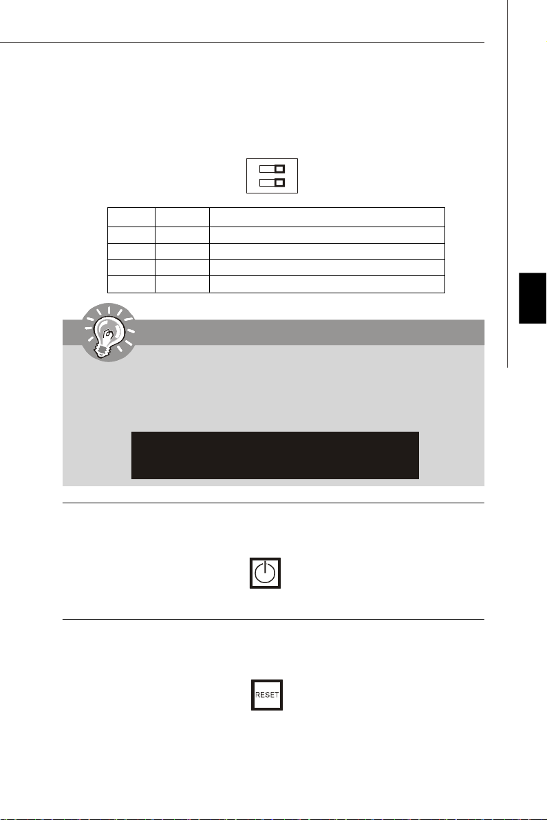
Interrupteur d’Overclock du FSB : U117 (optionnel)
1
2
O
N
Vous pouvez overclocker le FSB pour augmenter la fréquence du processeur en
changeant l’interrupteur. Suivez les instructions suivantes pour régler le FSB.
DOC1 DOC2 Fréquence du CPU
1:ON 2:ON Défaut
1:ON 2:OFF Augmenter par 10% de la vitesse du FSB
1:OFF 2:ON Augmenter par 15% de la vitesse du FSB
1:OFF 2:OFF Augmenter par 20% de la vitesse du FSB
Important
1.Veuillez vous assurer d’éteindre le système avant de régler l’interrupeur.
2.Lorsque l’overclocking des matériaux entraîne une instabilité du système
ou des fracas pendant l’initialisation, il apparaîtra un message d’alarme
durant POST comme ci-dessous. Après, veuillez régler l’interrupteur en
statut par défaut.
Warning!!! OC switch overclocking had failed,
Please shutdown and adjust oc switch to lower frequency.
Try again!
Français
Bouton d’alimentation : POWER1
Ce bouton d’alimentation sert à allumer ou éteindre le système. Appuyez sur ce bouton
pour allumer ou éteindre le système.
Bouton de réinitialisation : RESET1
Ce bouton de réinitialistion sert à réinitialiser le système. Appuyez sur ce bouton pour
réinitialiser le système.
Fr-13
Page 78

Carte mère MS-7550
Bouton d’effacement du CMOS : CLR_CMOS1
Il y a un CMOS RAM intégré, qui possède un bloc d’alimentation alimenté par une
batterie externe, destiné à conserver les données de configuration du système Avec le
CMOS RAM, le système peut lancer automatiquement le système d’exploitation chaque
fois qu’il est allumé. Si vous souhaitez effacer la configuration du système, appuyez sur
ce bouton de manière à effacer les données.
Important
Veuillez vous assurer d’éteindre le système avant d’effacer off the les données
de CMOS.
Fr-14
Page 79

Attachement d’Alimentation: ATX1
Avant d’insérer le connecteur d’alimentation, assurez-vous toujours que tous les
composants sont installés correctement afin de ne pas causer de dommage. Tous les
connecteurs de puissance sur la carte mère doivent se relier à l’alimentation d’ATX et
doivent travailler ensemble pour une opération stable.
Connecteur d’alimentation ATX 24-Pin : ATX1
Ce connecteur vous permet de connecter l’alimentation ATX 24-pin. Pour cela, assurez
-vous que la prise d’alimentation est bien positionnée dans le bon sens et que les
goupilles soient alignées. Enfoncez alors la prise dans le connecteur.
Vous pourvez aussi utiliser un alimentation 20-pin selon vos besoins. Veuillez brancher
votre alimentation d’énergie avec le pin 1 et le pin 13 si vous voulez utiliser l’alimentation
ATX 20-pin.
13
1
NC
1224
+3.3V
+3.3V
GND
+5V
GND
+5V
GND
PWR OK
5VSB
+12V
+12V
+3.3VGND
+3.3V
-12V
GND
PS-ON#
GND
GND
GND
+5V
+5V
+5V
Connecteur d’alimentation ATX 12V (2x2-Pin) : PWR1
Le connecteur d’alimentation de 12V fournit de l’alimentation au CPU.
Français
GND
GND
1 3
2
12V
12V
4
Fr-15
Page 80

Carte mère MS-7550
Slot PCI Express (x16/ x1)
Le slot PCI Express supporte la carte d’extension d’interface de PCI Express.
Slot PCI Express x16
Slot PCI Express x 1
Slot PCI (Peripheral Component Interconnect)
Les slots PCI supportent les cartes LAN, les cartes SCSI, les cartes USB, et les autres
cartes d’ajout conformes aux spécifications PCI.
Important
Lorsque vous ajoutez ou que vous retirez les cartes d’extension, assurez-vous
d’avoir débranché en premier le bloc d’alimentation. Pendant ce temps, lisez la
documentation de la carte d’extension afin de configurer les réglages nécessaires
de matériel ou de logiciel pour la carte d’extension, comme les cavaliers, les
interrupteurs ou la configuration BIOS.
Fr-16
Page 81

Panneau arrière
Souris/Clavier
Le standard connecteur de souris/clavier DIN de PS/2® est pour une souris ou un clavier
de PS/2®.
Port VGA
Le connecteur féminin de DB15-pin est fournit pour le moniteur.
15
(DIN Connecteur fé minin de 15-Pin)
1115
Port DVI
Le connecteur DVI (Digital Visual Interface) vous permet de connecter un moniteur
LCD. Il founit une interconnexion numérique de haute vitesse entre l’ordinateur et ses
périphériques de l’écran. Afin de connecteur un moniteur de LCD, vous n’avez qu’à
brancher votre câble de moniteur dans le connecteur DIV, et vous assurer que l’autre
côté du câble est correctement connecté ) votre moniteur ( Veuillez vous référer au
manuel de votre moniteur pour plus d’informations).
8
1
17
24
Important
Veuillez noter que le connecteur DVI ne supporte pas la connexion d’un D-Sub
à un convertisseur DVI.
S/PDIF-out optique
Ce connecteur est utilisé pour relier à l’interface S/PDIF (Sony & Philips Digital Interconnect Format) de la transmission audio numérique par un câble de fibre optique.
Français
Fr-17
Page 82

Carte mère MS-7550
Port HDMI
Le High-Definition Multimedia Interface (HDMI) est un interface d’audio-vidéo tout-
numérique, capable de trasmettre les flux décompressés. HDMI supporte toute forme de
TV, y compris le standard, l’intégré, ou le vidéo high-definition, avec l’audio numérique
de multi-canaux sur un câble simple.
Port 1394
Le port IEEE1394 sur le panneau arrière fournit une connexion aux périphériques
IEEE1394.
Port USB
Le port USB (Universal Serial Bus) sert à brancher des périphériques USB tel que le
clavier, la souris, ou d’autre périphériques compatibles USB.
Port SATA Externe
Le port eSATA (External Serial ATA) sert à connecter le périphérique externe de SATA.
Vous pouvez aussi utiliser ce câblede SATA externe pour connecter un périphérique
SATA et un port eSATA.
Fr-18
Page 83

LAN
La prise standard RJ-45 LAN sert à la connexion au réseau local (Local Area Network
(LAN)). Vous pouvez y relier un câble de réseau.
LED Couleur LED Statut Condition
Eteinte La connexion au réseau LAN n’est pas établie.
Gauche Orange Allumée (stable) La connexion au réseau LAN est établie.
Allumée (plus brillant et
clignotante)
Vert Eteinte
Droite Allumée
Orange Allumée
L’ ordinateur communique avec un autre ordinateur
sur le réseau local LAN.
Un débit de 10 Mo/sec est sélectionné.
Un dé bit de 100 Mo/sec est sélectionné.
Un débit de 1000 Mo/sec est s électionné.
Connecteurs de port audio
Ces connecteurs audio servent pour les périphériques audio. Vous pouvez différencier
la couleur des prises audio pour obtenir divers effets sonores.
Français
Ligne-In (Bleu) - Ligne In, est utilisé pour un appareil de CD externe, cassette ou d’autre
périphériques.
Ligne-Out (Vert) - Ligne Out, est destiné aux haut-parleurs ou aux casques d’écoute.
MIC (Rose) - Mic In est un connecteur pour les microphones.
RS-Out (Noir) - Rear-Surround Out en mode de canal 4/ 5.1/ 7.1.
CS-Out (Orange) - Center/ Subwoofer out en mode de canal 5.1/ 7.1.
SS-Out (Gris) - Side-Surround Out en mode de canal 7.1.
Fr-19
Page 84

Carte mère MS-7550
Réglages BIOS
Ce chapitre donne des informations concernant le programme de réglage de BIOS et
vous permet de configurer le système pour obtenir des performances d’utilisation optimum.
Vous aurez peut-être besoin de lancer le programme de réglage quand :
* Un message d’erreur apparaît sur l’écran pendant le démarrage du système, qui vous
demande de lancer SETUP (Réglage).
* Vous souhaitez changer les réglages par défaut des fonctions personnalisées.
Important
1.Les objets situés sous chaque catégorie BIOS décrits dans ce chapitre sont en
cours de mise à jour continue pour améliorer les performances du système.
C'est pourquoi il est possible que la description soit légèrement différente du
BIOS le plus récent, et ne doit servir que comme référence.
2.Au redémarrage, la premiè re ligne qui apparaît après le compte de la mémoire,
est la version BIOS. Elle est généralement sous la forme :
A7550AMS V1.0 010108 où :
Le premier caractère se rapporte au fabricant du BIOS : A = AMI, W = AWARD, and
P = PHOENIX.
Les caractères du second au cinquième caractère se rapportent
au numéro de modèle.
Le sixième caractère se rapporte au jeu de puces : A = AMD, I = Intel, V = VIA, N
= Nvidia,
Les septième et huitième caractère se rapportent au client : MS = all standard
customers (Tous les clients standard).
V1.0 se rapporte à la version de BIOS.
010108 se rapporte à la date à laquelle est sortie ce BIOS.
Fr-20
Page 85

Réglages d’Entrée
Allumez l'ordinateur et le système lancera le processus POST (Test automatique
d'allumage). Lorsque le message ci-dessous apparaît à l'écran, appuyez sur la touche
<DEL> pour entrer dans les réglages.
Appuez sur DEL pour entrer dans SETUP (Réglages)
Si le message disparaît avant que vous ne répondiez et que vous souhaitez encore
entrer dans Setup (Réglages), redémarrez le système en OFF (éteignant) puis en On
(rallumant) en appuyant sur le bouton RESET (Réinitialiser). Vous pouvez également
redémarrer le système en appuyant simultanément sur les touches <Ctrl>, <Alt>, et
<Delete>.
Obtenir de l’aide
Après être entré dans le menu de Réglage, le premier menu que vous verrez apparaître
sera le menu principal.
Menu principal
Le menu principal établit la liste des fonctions de réglage que vous pouvez modifier.
Vous pouvez utiliser les touches de flèche (↑↓) pour sélectionner l'objet. La descrip-
tion en ligne des fonctions de réglages illuminées est affichée
au bas de l'écran.
Sous-Menu
Si vous un symbole de pointeur droit (comme indiqué sur la vue de droite) apparaît sur
la gauche de certains champs, cela signifie qu'un sous-menu peut être lancé à partir de
ce champ. Un sous-menu contient des options supplémentaires pour un param ètre de
champ. Vous pouvez utiliser les touches de flèche (↑↓ ) pour illuminer le champ puis
appuyez sur <Enter> (Entrer) pour faire apparaître le sous-menu. Vous pourrez alors
utiliser les touches de commande pour saisir des valeurs et vous déplacer d'un champ
à un autre à l'intérieur d'un sous-menu. Si vous souhaitez revenir au menu principal,
appuyez juste sur <Esc>.
Français
Aide générale <F1>
Le programme de réglages BIOS fournit un écran d'aide générale. Vous pouvez faire
sortir cet écran à partir de n'importe quel menu en appuyant simplement sur <F1>.
L'écran d'aide donne une liste des touches appropriées à utiliser et les sélections
possibles pour l'objet illuminé. Appuyez sur <Esc> pour quitter l'écran d'aide.
Fr-21
Page 86

Carte mère MS-7550
Menu principal
Une fois entré dans l’unité de réglages AMI® ou AWARD® BIOS CMOS, le Menu principal
appaît sur l’écran. Le Menu Principal vous permet de sélectionner de dix foncions de
réglage et deux choix de sortie. Utilisez les touches de flèche pour sélectionner parmi
les objets et appuyez sur <Enter> pour accepter ou entrer dans le sous-menu.
Standard CMOS Features (Fonctions CMOS standard)
Utilisez ce menu pour les configurations du système de base, tel que l’heure, la date.
Advanced BIOS Features (Fonctions BIOS avancées)
Utilisez ce menu pour régler les objets des fonctions am éliorées spéciales.
Integrated Peripherals (Périphériques intégrés)
Utilisez ce menu pour définir vos régléges des périphériques intégrés.
Power Management Features (Fonctions de la gestion de l’énergie)
Utilisez ce menu pour définir vos réglages de la gesion de l’énergie.
H/W Monitor (Moniteur H/W)
Cette entrée indique l’état de santé de votre PC.
BIOS Setting Password (Mot de passe de réglage BIOS)
Utilisez ce menu pour régler le mot de passe.
Cell Menu (Menu cell)
Utilisez ce menu pour définir vos réglages du contrôle de la fréquence/voltage et de
l’overclocking.
User settings (Réglages d’utilisateurs)
Utilisez ce menu pour sauvegarder/ charger vos réglages au/ du CMOS pour BIOS.
Load Fail-Safe Defaults (Défauts de sécurité de chargement intégrée)
Utilisez ce menu pour charger les valeur par défauts réglées par le vendeur de BIOS
afin de garantir la stabilité des performances du système.
Load Optimized Defaults (Chargement des réglages par défaut optimisés)
Utilisez ce menu pour charger les valeurs par défaut réglées par le fabricant de la carte
mère spécifiquement pour obtenir des performances optimales de la carte mère.
Save & Exit Setup (Sauvegarder et quitter les réglages)
Sauvegardez les changements apportés au CMOS puis quittez les réglages.
Exit Without Saving (Quitter sans sauvegarder)
Abandonnez tous les changements et quittez les réglages.
Fr-22
Page 87

Quand vous entrez dans l’unité de réglages BIOS, suivez les procédures suivantes pour
l’utilisation générale.
1. Load Optimized Defaults (chargement des réglages par défaut optimisés) : Utilisez
les touches de contrôle (↑↓ ) afin de surligner le domaine Load Optimized Defaults
et appuyez sur <Enter> , le message suivant apparaîtra :
Choisir [Ok] et appuyer sur Enter chargera les valeurs défauts de BIOS pour un
système minimal plus stable.
2. Setup Date/ Time (Réglage de l’heure et de la date) : Choisissez Standard CMOS
Features et appuyez sur <Enter> afin d’entrer dans le menu Standard CMOS Features.
Ajustez la date et l’heure.
3. Save & Exit Setup (Sauvegarder et quitter les réglages) : Utilisez les touches de
contrôle (↑↓ ) afin de surligner le domaine de Save & Exit Setup et appuyez sur
<Enter> , le message suivant apparaîtra :
Français
Choisir [Ok] et appuyer sur Enter afin de sauvegarder les configurations et l’unité de
réglages de quitter BIOS.
Important
Les configurations précédantes ne sont que pour l’utilisation générale. Si vous
avez besoin de réglages détaillés du BIOS, veuillez vous référer au manuel de
l’édition anglaise sur la page d’internet de MSI.
Fr-23
Page 88

Carte mère MS-7550
4. Cell Menu Introduction (Introduction du Menu cell) : Ce menu est pour des utilisations
avancée destinée à overclocker la carte mère.
Important
Ne changez pas ces réglages sauf que vous connaissiez bien ces chipsets.
Current CPU / DRAM Frequency (Fréquence actuelle du CPU/ DRAM)
Ces articles montrent les horloges actuelles de la vitesse du CPU et de la mémoire.
Lecture uniquement.
AMD Cool’n’Quiet
La technologie Cool’n’ Quiet peut effectivement et dynamiquement baisser la vitesse
du CPU et la consommation de l’alimentation.
Fr-24
Page 89

Important
Afin d’assurer que la fonction Cool’n’Quiet
soit activée et qu’elle fonctionne
correctement, il est nécessaire de
confirmer que:
1.Entrez dans BIOS Setup, et choisissez
Cell Menu. Sous Cell Menu, trouvez AMD
Cool’n’Quiet, et réglez cet article en
“Activé.”
2.Entrez dans Windows, et choisissez
[Start]->[Settings]->[Control Pannel]->
[Power Options]. Entrez dans le repère
Power Options Properties, et choisissez
Minimal Power Management sous Power
schemes.
Adjust CPU FSB Frequency (MHz) (Ajustement de la fréquence du FSB du CPU)
Cet artible vous permet de sélectionner la fréquence d’horloge du FSB du CPU.
Adjust CPU Ratio (Ajustement du Ratio du CPU)
Cet article vous permet d’ajuster le ratio du CPU. Il est disponible seulement quand le
processeur supporte cette fonction.
Adjust CPU-NB Ratio (for AM2+ CPU only) (Ajustement du Ratio du CPU-NB, que
pour AM2+ CPU)
Cet article vous permet d’ajuster le ratio du NB du CPU. Il est disponible seulement
quand le processeur supporte cette fonction.
Adjusted CPU Frequency (MHz) (Ajustement de la fréquence du CPU)
Il montre la fréquence ajustée du CPU (FSB x Ratio). Lecture uniquement.
Français
Advanced Clock Calibration (for AM2+ CPU only) (Calibration d’horloge avancé,
que pour AM2+ CPU)
Cet article est pour l’overclocking. Mis en [Enabled], il vous permet d’augmenter le
Ratio du CPU un peu plus haut.
Onboard VGA Core Overclock (Overclock du core VGA intégré)
Cet article sert à activer/ désactiver l’overclock du core VGA intégré.
Advance DRAM Configuration (Avancer les configurations du DRAM)
Appuyez sur <Enter> pour entrer dans le sous-menu.
MEMORY-Z
Appuyez sur <Enter> pour entrer dans le sous-menu.
DIMM1/2/3/4 Memory SPD Information
Appuyez sur <Enter> pour entrer dans le sous-menu.
Fr-25
Page 90

Carte mère MS-7550
E.P.P SUPPORT Information
Appuyez sur <Enter> pour entrer dans le sous-menu.
DRAM Timing Mode
Mis en [Auto], DRAM CAS# Latency sera automatiquement déterminé par BIOS
basé sur les configurations sur le SPD (Serial Presence Detect) EEPROM sur le
module DRAM.
1T/2T Memory Timing
Cet article contrôle le taux d’ordre de SDRAM. Mis en [1T], le contrôle de signal
de SDRAM fonctionne au taux de 1T (T=cycles d’horloge). Mis en [2T], le
contrôle de signal de SDRAM fonctionne au taux de 2T.
Bank Interleaving
Ce domaine choisit l’entrelacement 2-bank ou 4-bank pour le SDRAM installé.
Désactivez cette fonction si 16MB SDRAM est installé.
DCT Unganged Mode
Cela sert à activer/ désactiver le Mode DCT Unganged (que pour Phenom).
EPP Technology Support
Cela sert à activer/ désactiver la technologie EPP.
FSB/DRAM Ratio
Cet article vous permet d’ajuster le ratio du FSB to à la mémoire.
Adjusted DRAM Frequency (MHz)
Il montre la fréquence de la mémoire DDR ajustée. Lecture-uniquement.
HT Link Speed
Cet article vous permet de régler la vitesse du Hyper-Transport Link. Mis en [Auto], le
système détectera la vitesse du HT link automatiquement.
Adjust PCI-E Frequency (MHz)
Ce domaine vous permet de sélectionner la fréquence du PCIE (en MHz).
Auto Disable PCI Frequency (Fréquence du PCI désactivé automatique)
Quand il est mis en [Enabled], le système éteindra l’horloge des fentes vides de PCI
pour réduire au minimum l’interface électromagnétique (EMI).
CPU VDD Voltage (V) / CPU-NB VDD Voltage (V)/ CPU Voltage (V) / CPU-NB
Voltage (V)/ DRAM Voltage (V)/ NB Voltage (V)/ HT Link Voltage (V)/ MCT Voltage (V)
Ces articles servent à ajuster le voltage du CPU, de la mémoire, du FSB et du chipset.
Spread Spectrum
Lorsque le clock generator de la carte mère fonctionne, les valeurs extrêmes (spikes)
créent des interférences électromagnétiques (EMI-Electromagnetic Interference). La
fonction Spread Spectrum réduit ces interférences en réglant les impultions. Si vous
n’avez pas de problème d’EMI ceci vous permet d’avoir une stabilité du système et
des performances optimales. Dans le cas contraire, choisissez Enabled pour réduire
les interférences. N’oubliez pas de désactiver cette fonction si vous voulez faire de
l’overclocking, parce que la moindre modification peut entraîner une accélération
temporaire d’horloge et ainsi votre processeur overclocké se verrouillera.
Fr-26
Page 91

Important
1.Si vous n’avez pas de problème d’EMI, laissez l’option sur [Disabled] ceci
vous permet d’avoir une stabilité du système et des performances optimales.
Dans le cas contaire, choisissez Spread Spectrum pour réduire les EMI.
2.Plus la valeur Spread Spectrum est importante, plus les EMI sont réduites, et
le système devient moins stable. Pour la valeur Spread Spectrum la plus
convenable, veuillez consulter le règlement EMI local.
3.N’oubliez pas de désactiver la fonction Spread Spectrum si vous êtes en
train d’overclocker parce que même un battement léger peut causer un
accroissement temporaire de la vitesse de l’horloge qui verrouillera votre
processeur overclcké.
Français
Fr-27
Page 92

Carte mère MS-7550
Information de Logiciel
Sortez le pilote/ Service du CD, qui est inclus dans le paquet de la carte mère et
placez-le dans le CD-ROM.L’installation va automatiquement se déclencher, cliquez
sur le pilote ou sur l’usage et suivez le pop-up de l’écran pour accomplir l’installation.
Le pilote/Service CD contient :
Menu de pilote – Il montre les pilotes disponibles. Installez le pilote si vous le
souhaitez pour activer le dispositif.
Menu de services – Il montre les applications logicielles supportées par la carte mère.
Menu du site Web – Il vous indique les sites webs utiles.
Important
Veuillez consulter le site Web de MSI pour obtenir les derniers pilotes et BIOS
pour améliorer l’exécution du système de votre ordinateur.
Fr-28
Page 93

Серия DKA790GX
Platinum
Руководство
пользователя
Русский
Русский
Ru-1
Page 94

MS-7550 Системная плата
Характеристики
Процессоры
- Процессоры AM2+ Phenom FX/X4/X3/X2
- Процессоры Athlon 64/FX/X2
(Для получения новых сведений о процессорах посетите сайт
http://global.msi.com.tw/index.php?func=cpuform)
HyperTransport
- Поддержка HyperTransport 3.0
Чипсет
- Северный мост: AMD® 790GX
- Южный мост: AMD® SB750
Память
- DDR2 667/800/1066 SDRAM (8GB Max)
- 4 слота DDR2 DIMM (240pin / 1.8V)
* (За дополнительной информацией о совместимых
компонентах посетите сайт http://global.msi.com.tw/index.php?
func=testreport)
LAN
- Поддержка LAN 10/100/1000 Fast Ethermet на микросхеме
RTL8111C
IEEE 1394
- Интегрированный чипсет Jmicron JMB381
- Скорость передачи данных до 400Мб/с
- 1 порт
Ru-2
Аудио
- HD аудио ALC888
- 8-ми канальное аудио с гибким переназначением
IDE
- 1 порт IDE на чипсете SB750
- Поддержка режимов Ultra DMA 66/100/133
- Поддержка режимов работы PIO, Bus Master
SATA
- SATA II порты на чипсете SB750
- Поддержка 5 устройств SATA II
- Поддержка скорости передачи данных до 3Гб/с
eSATA
- Поддержка 1 e-SATA порт на чипсете SB750
- Поддержка скорости передачи данных до 3Гб/с
Page 95

RAID
- SATA1~5 поддерживают режимы RAID 0/ 1/ 0+1/ 5 или JBOD на
чипсете SB750
Флоппи
- 1 флоппи порт
- Поддержка 1 FDD с 360КБ, 720КБ, 1.2МБ, 1.44МБ И 2.88МБ
Коннекторы
Задней панели
- 1 PS/2 порт мыши или клавиатуры
- 1 порт IEEE 1394
- 6 портов USB 2.0
- 1 разъем LAN
- 6 звуковых разъемов с гибким переназначением
- 1 оптический разъем SPDIF
- 1 порт e-SATA
- 1 порт DVI-D
- 1 порт VGA
- 1 порт HDMI
Разъемы, установленные на плате
- 3 разъема USB 2.0
- 1 разъем для порта COM
- 1 разъем CD-in
- 1 разъем TPM модуля
- 1 разъем датчика открывания корпуса
- 1 разъем для аудио на передней панели
- 1 разъем Wake on LAN
Слоты
- 2 слота PCI Express x16
(поддержка 2 x PCI-E x8 CrossFire)
- 2 слота PCI Express x1
- 2 слота PCI
Русский
Форм Фактор
- ATX (30.4см X 24.5 см)
Крепление
- 9 отверстий для крепления
Ru-3
Page 96

MS-7550 Системная плата
Mouse/
Keyboard,
p.Ru-17
USB ports,
p.Ru-18
VGA Port,
p.Ru-17
DVI-D Port,
p.Ru-17
JPWR2,
p.Ru-15
CPU,
p.Ru-5
SPDIF out,
p.Ru-17
HDMI Port,
p.Ru-18
JCI1,
p.Ru-11
1394 port,
p.Ru-18
eSATA port,
p.Ru-18
WOL1,
p.Ru-12
LAN,
p.Ru-19
RS-Out
L-In
L-Out
CS-Out
Mic
SS-Out
Audio Port,
p.Ru-19
DDR2,
p.Ru-7
JPWR1,
p.Ru-15
SYS_FAN1,
p.Ru-13
PCI_E,
p.Ru-16
U117,
p.Ru-13
PCI,
p.Ru-16
JFP1,
p.Ru-10
POWER1,
p.Ru-13
RESET1,
p.Ru-13
JCD1,
p.Ru-10
JAUD1,
p.Ru-12
SYS_FAN2,
p.Ru-9
FDD1,
p.Ru-9
JUSB1~3,
p.Ru-11
CLR_CMOS1,
p.Ru-14
Руководство по размещению компонентов на системных
Ru-4
платах серий DKA790GX Platinum (MS-7550 v1.X)
CPU_FAN1,
p.Ru-9
IDE1,
p.Ru-9
JTPM,
p.Ru-12
SATA1~5,
p.Ru-10
JCOM1,
p.Ru-11
JFP2,
p.Ru-10
Page 97

Центральный процессор: CPU
Correct CPU
Эта системная плата поддерживает процессоры от AMD®. Для облегчения
установки процессора на ней установлен разъем под названием Socket AM2/
AM2+. Если у вас нет процессорного кулера, пожалуйста, свяжитесь с дилером с
целью приобретения и его установки до того, как включите компьютер.
Самую последнюю информацию о CPU можно получить на сайте http://global.msi.
com.tw/index.php?func=cpuform
Внимание
Перегрев
Перегрев может серьезно повредить центральный процессор и систему.
Чтобы уберечь процессор от перегрева, убедитесь в том, что
процессорный кулер работает нормально. Чтобы увеличить
теплорассеивание, убедитесь в том, что нанесен слой теплопроводящей
пасты (или теплопроводящей ленты) между процессором и радиатором.
Замена CPU
При замене CPU, во избежание его повреждения, обязательно отключите
источник питания или выньте вилку блока питания из розетки.
Разгон
Эта системная плата поддерживает “разгон”. Однако, убедитесь, что
компоненты системы способны работать в таких нестандартных режимах
при разгоне. Не рекомендуется использовать продукт в режимах, не
соответствующих указанным в спецификациях. Мы не гарантируем
защиту от повреждений и рисков, вызванных неправильной
эксплуатацией и установкой параметров с превышением
характеристик.
Установка CPU в Socket AM2/ AM2+
1. Перед установкой CPU, пожалуйста, отключите
питание и выньте вилку блока питания из розетки.
2. Поднимите в вертикальное положение рычажок,
находящийся сбоку разъема.
3. Обратите внимание на золотую стрелку (Gold arrow)
Gold arrow
на CPU. Она должна быть направлена так, как показано
на рисунке. CPU можно вставить только при
правильной ориентации.
4. При правильной установке CPU его контакты полностью войдут в разъем, и их
не будет видно. Помните, что любое применение силы при установке CPU
может вызвать серьезные повреждения системной платы.
5. Аккуратно прижмите CPU к разъему и опустите рычажок. Поскольку CPU при
опускании рычажка может переместиться, осторожно прижимайте CPU
пальцами в центре, так, чтобы он правильно и полностью зафиксировался в
разъеме.
placement
Русский
Ru-5
Page 98

MS-7550 Системная плата
Установка вентилятора процессора
Во избежание перегрева при работе обязательно установите вентилятор
процессора. Если у вас нет процессорного вентилятора, пожалуйста, свяжитесь
с дилером с целью приобретения и его установки до того, как включите компьютер.
Внимание
Фото системной платы, размещенные в этой части, приведены только для
демонстрации установки вентилятора. Фактический вид системной платы
зависит от модели, купленной вами.
1. Разместите радиатор на узле крепления. В начале зацепите один его край.
2. Затем нажмите на другой край, чтобы установить радиатор на узел крепления.
Найдите рычаг фиксации и поднимите его.
3. Зафиксируйте радиатор дальнейшим поворотом рычага.
4. Подключите кабель вентилятора CPU к соответствующему разъему системной
платы.
Fixed Lever
Ru-6
Page 99

Память
1
2
3
Installed
Слоты DIMM используются для установки модулей памяти.
За дополнительной информацией о совместимых компонентах посетите сайт
http://global.msi.com.tw/index.php?func=testreport
DDR2
240-pin, 1.8V
64x2=128 pin56x2=112 pin
Правила установки модулей памяти для работы в
двухканальном режиме
В двухканальном режимемодули памяти могут передавать и принимать данные
по 2 шинам одновременно. При использовании двухканального режима
производительность системы повышается. Ниже приведены правила
заполнения слотов памяти для работы в двухканальном режиме.
DIMM1
DIMM2
DIMM3
DIMM4
DIMM1
DIMM2
DIMM3
DIMM4
Русский
DIMM1
DIMM2
DIMM3
DIMM4
Empty
Ru-7
Page 100

MS-7550 Системная плата
Установка модулей памяти
1. Модули памяти имеют только одну прорезь в середине. Модуль войдет в
разьем только при правильной ориентации.
2. Вставьте модуль в DIMM слот в вертикальном направлении. Затем нажмите на
него, чтобы золоченые контакты глубоко погрузились в DIMM слот. Если модуль
памяти вставлен правильно, то пластиковые защелки на обоих концах закроются
автоматически.
Внимание
Золотые контакты едва видны, если модули памяти правильно размещены
в DIMM слоте.
3. Вручную убедитесь, что модуль закреплен в слоте DIMM защелками с обеих
сторон.
Volt
Notch
Внимание
- Модули DDR2 не взаимозаменяемы с модулями DDR, и стандарт DDR2
не имеет обратной совместимости. Следует устанавливать модули
памяти DDR2 в разъемы DDR2 DIMM и модули памяти DDR в разъемы
DDR DIMM.
- Для работы в двухканальном режиме убедитесь, что в разъемах разных
каналов у вас установлены модлуи одного типа и одинаковой
емкости.
- Чтобы система загрузилась, вначале установите модули в разъем
DIMM1.
Ru-8
 Loading...