

Page 1
Wind Board
D510/ D410 series
Wind Board
D510/ D410 series
MS-7618 (v1.x) Mainboard
i
G52-76181X2
Page 2
Preface
Copyright Notice
MICRO-STAR INTERNA-
TIONAL
Trademarks
Revision History
Revision
Revision History
Date
Technical Support
http://www.msi.com/index.php?func=service
http://ocss.msi.com
Preface
▍
Copyright Notice
The material in this document is the intellectual property of
TIONAL. We take every care in the preparation of this document, but no guarantee is
given as to the correctness of its contents. Our products are under continual improvement and we reserve the right to make changes without notice.
Trademarks
All trademarks are the properties of their respective owners.
®
is registered trademark of Micro-Star Int’l Co.,Ltd.
■
MSI
®
is registered trademark of NVIDIA Corporation.
NVIDIA
■
®
■
is registered trademark of ATI Technologies, Inc.
ATI
®
is registered trademarks of AMD Corporation.
■
AMD
®
is registered trademarks of Intel Corporation.
Intel
■
■
■
■
■
■
■
■
Revision History
Revision
V1.0 First release for PCB 1.x February 2010
Technical Support
If a problem arises with your system and no solution can be obtained from the user’s
manual, please contact your place of purchase or local distributor. Alternatively, please
try the following help resources for further guidance.
®
is registered trademarks of Microsoft Corporation.
Windows
®
is registered trademark of American Megatrends Inc.
AMI
®
Award
is a registered trademark of Phoenix Technologies Ltd.
®
Sound Blaster
Realtek
JMicron
Netware
is registered trademark of Creative Technology Ltd.
®
is registered trademark of Realtek Semiconductor Corporation.
®
is registered trademark of JMicron Technology Corporation.
®
is a registered trademark of Novell, Inc.
Revision History
MICRO-STAR INTERNA-
Date
◙
Visit the MSI website for FAQ, technical guide, BIOS updates, driver updates,
and other information:
◙
Contact our technical staff at:
http://www.msi.com/index.php?func=service
http://ocss.msi.com
ii
Page 3

MS-7618
Safety Instructions
CAUTION
Safety Instructions
■
Always read the safety instructions carefully.
■
Keep this User’s Manual for future reference.
■
Keep this equipment away from humidity.
■
Lay this equipment on a reliable fl at surface before setting it up.
■
The openings on the enclosure are for air convection hence protects the equipment
from overheating. DO NOT COVER THE OPENINGS.
■
Make sure the voltage of the power source and adjust properly 110/220V before
connecting the equipment to the power inlet.
■
Place the power cord such a way that people can not step on it. Do not place anything over the power cord.
■
Always Unplug the Power Cord before inserting any add-on card or module.
■
All cautions and warnings on the equipment should be noted.
■
Never pour any liquid into the opening that could damage or cause electrical
shock.
■
If any of the following situations arises, get the equipment checked by service
personnel:
◯
The power cord or plug is damaged.
◯
Liquid has penetrated into the equipment.
◯
The equipment has been exposed to moist ure.
◯
The equipment does not work well or you can not get it work according to User’s
Manual.
◯
The equipment has dropped and damaged.
◯
The equipment has obvious sign of breakage.
DO NOT LEAVE THIS EQUIPMENT IN AN ENVIRONMENT UNCONDITIONED,
STORAGE TEMPERATURE ABOVE 60
MENT.
CAUTION: Danger of explosion if battery is incorrectly replaced.
Replace only with the same or equivalent type recommended by the manufacturer.
警告使用者:
這是甲類資訊產品,在居住的環境中使用時,可能會造成無線電干擾,在這種情況下,
使用者會被要求採取某些適當的對策。
廢電池請回收
For better environmental protection, waste batteries should be
collected separately for recycling special disposal.
0
C (1400F), IT MAY DAMAGE THE EQUIP-
iii
Page 4
Preface
FCC-B Radio Frequency Interference Statement
Preface
▍
FCC-B Radio Frequency Interference Statement
This equipment has been tested and found
to comply with the limits for a Class B digital device, pursuant to Part 15 of the FCC
Rules. These limits are designed to provide
reasonable protection against harmful interference in a residential installation. This equipment generates, uses and can radiate
radio frequency energy and, if not installed and used in accordance with the instructions, may cause harmful interference to radio communications. However, there is no
guarantee that interference will not occur in a particular installation. If this equipment
does cause harmful interference to radio or television reception, which can be determined by turning the equipment off and on, the user is encouraged to try to correct the
interference by one or more of the measures listed below.
◯
Reorient or relocate the receiving antenna.
◯
Increase the separation between the equipment and receiver.
◯
Connect the equipment into an outlet on a circuit diff erent from that to which the
receiver is connected.
◯
Consult the dealer or an experienced radio/television technician for help.
Notice 1
The changes or modifi cations not expressly approved by the party responsible for com-
pliance could void the user’s authority to operate the equipment.
Notice 2
Shielded interface cables and A.C. power cord, if any, must be used in order to comply
with the emission limits.
VOIR LA NOTICE D’INSTALLATION AVANT DE RACCORDER AU RESEAU.
Micro-Star International
MS-7618
This device complies with Part 15 of the FCC Rules. Operation is subject to the following two conditions:
this device may not cause harmful interference, and
1)
this device must accept any interference received, including interference that may
2)
cause undesired operation.
iv
Page 5
MS-7618
WEEE (Waste Electrical and Electronic Equipment) Statement
ENGLISH
DEUTSCH
FRANÇAIS
РУССКИЙ
WEEE (Waste Electrical and Electronic Equipment) Statement
ENGLISH
To protect the global environment and as an environmentalist, MSI must
remind you that...
Under the European Union (“EU”) Directive on Waste Electrical and Electronic Equipment, Directive 2002/96/EC, which takes eff ect on August 13,
2005, products of “electrical and electronic equipment” cannot be discarded
as municipal waste anymore and manufacturers of covered electronic equipment will be obligated to take back such products at the end of their useful life. MSI will
comply with the product take back requirements at the end of life of MSI-branded products that are sold into the EU. You can return these products to local collection points.
DEUTSCH
Hinweis von MSI zur Erhaltung und Schutz unserer Umwelt
Gemäß der Richtlinie 2002/96/EG über Elektro- und Elektronik-Altgeräte dürfen Elek-
tro- und Elektronik-Altgeräte nicht mehr als kommunale Abfälle entsorgt werden. MSI
hat europaweit verschiedene Sammel- und Recyclingunternehmen beauftragt, die in
die Europäische Union in Verkehr gebrachten Produkte, am Ende seines Lebenszyklus
zurückzunehmen. Bitte entsorgen Sie dieses Produkt zum gegebenen Zeitpunkt ausschliesslich an einer lokalen Altgerätesammelstelle in Ihrer Nähe.
FRANÇAIS
En tant qu’écologiste et afi n de protéger l’environnement, MSI tient à rappeler ceci...
Au sujet de la directive européenne (EU) relative aux déchets des équipement élec-
triques et électroniques, directive 2002/96/EC, prenant eff et le 13 août 2005, que les
produits électriques et électroniques ne peuvent être déposés dans les décharges ou
tout simplement mis à la poubelle. Les fabricants de ces équipements seront obligés de
récupérer certains produits en fi n de vie. MSI prendra en compte cette exigence relative
au retour des produits en fi n de vie au sein de la communauté européenne. Par conséquent vous pouvez retourner localement ces matériels dans les points de collecte.
РУССКИЙ
Компания MSI предпринимает активные действия по защите окружающей среды,
поэтому напоминаем вам, что....
В соответствии с директивой Европейского Союза (ЕС) по предотвращению
загрязнения окружающей среды использованным электрическим и электронным
оборудованием (директива WEEE 2002/96/EC), вступающей в силу 13
августа 2005 года, изделия, относящиеся к электрическому и электронному
оборудованию, не могут рассматриваться как бытовой мусор, поэтому
производители вышеперечисленного электронного оборудования обязаны
принимать его для переработки по окончании срока службы. MSI обязуется
соблюдать требования по приему продукции, проданной под маркой MSI на
территории EC, в переработку по окончании срока службы. Вы можете вернуть
эти изделия в специализированные пункты приема.
v
Page 6

Preface
ESPAÑOL
NEDERLANDS
SRPSKI
POLSKI
Preface
▍
ESPAÑOL
MSI como empresa comprometida con la protección del medio ambiente, recomienda:
Bajo la directiva 2002/96/EC de la Unión Europea en materia de desechos y/o equi-
pos electrónicos, con fecha de rigor desde el 13 de agosto de 2005, los productos
clasifi cados como “eléctricos y equipos electrónicos” no pueden ser depositados en
los contenedores habituales de su municipio, los fabricantes de equipos electrónicos,
están obligados a hacerse cargo de dichos productos al termino de su período de vida.
MSI estará comprometido con los términos de recogida de sus productos vendidos en
la Unión Europea al fi nal de su periodo de vida. Usted debe depositar estos productos
en el punto limpio establecido por el ayuntamiento de su localidad o entregar a una
empresa autorizada para la recogida de estos residuos.
NEDERLANDS
Om het milieu te beschermen, wil MSI u eraan herinneren dat….
De richtlijn van de Europese Unie (EU) met betrekking tot Vervuiling van Electrische
en Electronische producten (2002/96/EC), die op 13 Augustus 2005 in zal gaan kunnen niet meer beschouwd worden als vervuiling. Fabrikanten van dit soort producten
worden verplicht om producten retour te nemen aan het eind van hun levenscyclus.
MSI zal overeenkomstig de richtlijn handelen voor de producten die de merknaam MSI
dragen en verkocht zijn in de EU. Deze goederen kunnen geretourneerd worden op
lokale inzamelingspunten.
SRPSKI
Da bi zaštitili prirodnu sredinu, i kao preduzeće koje vodi računa o okolini i prirodnoj
sredini, MSI mora da vas podesti da…
Po Direktivi Evropske unije (“EU”) o odbačenoj ekektronskoj i električnoj opremi, Direktiva 2002/96/EC, koja stupa na snagu od 13. Avgusta 2005, proizvodi koji spadaju
pod “elektronsku i električnu opremu” ne mogu više biti odbačeni kao običan otpad i
proizvođači ove opreme biće prinuđeni da uzmu natrag ove proizvode na kraju njihovog
uobičajenog veka trajanja. MSI će poštovati zahtev o preuzimanju ovakvih proizvoda
kojima je istekao vek trajanja, koji imaju MSI oznaku i koji su prodati u EU. Ove proizvode možete vratiti na lokalnim mestima za prikupljanje.
POLSKI
Aby chronić nasze środowisko naturalne oraz jako fi rma dbająca o ekologię, MSI przypomina, że...
Zgodnie z Dyrektywą Unii Europejskiej (“UE”) dotyczącą odpadów produktów elektrycznych i elektronicznych (Dyrektywa 2002/96/EC), która wchodzi w życie 13 sierpnia
2005, tzw. “produkty oraz wyposażenie elektryczne i elektroniczne “ nie mogą być traktowane jako śmieci komunalne, tak więc producenci tych produktów będą zobowiązani
do odbierania ich w momencie gdy produkt jest wycofywany z użycia. MSI wypełni
wymagania UE, przyjmując produkty (sprzedawane na terenie Unii Europejskiej) wycofywane z użycia. Produkty MSI będzie można zwracać w wyznaczonych punktach
zbiorczych.
vi
Page 7

MS-7618
TÜRKÇE
ČESKY
MAGYAR
ITALIANO
TÜRKÇE
Çevreci özelliğiyle bilinen MSI dünyada çevreyi korumak için hatırlatır:
Avrupa Birliği (AB) Kararnamesi Elektrik ve Elektronik Malzeme Atığı, 2002/96/EC
Kararnamesi altında 13 Ağustos 2005 tarihinden itibaren geçerli olmak üzere, elektrikli
ve elektronik malzemeler diğer atıklar gibi çöpe atılamayacak ve bu elektonik cihazların
üreticileri, cihazların kullanım süreleri bittikten sonra ürünleri geri toplamakla yükümlü
olacaktır. Avrupa Birliği’ne satılan MSI markalı ürünlerin kullanım süreleri bittiğinde MSI
ürünlerin geri alınması isteği ile işbirliği içerisinde olacaktır. Ürünlerinizi yerel toplama
noktalarına bırakabilirsiniz.
ČESKY
Záleží nám na ochraně životního prostředí - společnost MSI upozorňuje...
Podle směrnice Evropské unie (“EU”) o likvidaci elektrických a elektronických výrobků
2002/96/EC platné od 13. srpna 2005 je zakázáno likvidovat “elektrické a elektronické
výrobky” v běžném komunálním odpadu a výrobci elektronických výrobků, na které se
tato směrnice vztahuje, budou povinni odebírat takové výrobky zpět po skončení jejich životnosti. Společnost MSI splní požadavky na odebírání výrobků značky MSI,
prodávaných v zemích EU, po skončení jejich životnosti. Tyto výrobky můžete odevzdat
v místních sběrnách.
MAGYAR
Annak érdekében, hogy környezetünket megvédjük, illetve környezetvédőként fellépve
az MSI emlékezteti Önt, hogy ...
Az Európai Unió („EU”) 2005. augusztus 13-án hatályba lépő, az elektromos és elektronikus berendezések hulladékairól szóló 2002/96/EK irányelve szerint az elektromos
és elektronikus berendezések többé nem kezelhetőek lakossági hulladékként, és az
ilyen elektronikus berendezések gyártói kötelessé válnak az ilyen termékek visszavételére azok hasznos élettartama végén. Az MSI betartja a termékvisszavétellel kapcsolatos követelményeket az MSI márkanév alatt az EU-n belül értékesített termékek
esetében, azok élettartamának végén. Az ilyen termékeket a legközelebbi gyűjtőhelyre
viheti.
ITALIANO
Per proteggere l’ambiente, MSI, da sempre amica della natura, ti ricorda che….
In base alla Direttiva dell’Unione Europea (EU) sullo Smaltimento dei Materiali Elettrici
ed Elettronici, Direttiva 2002/96/EC in vigore dal 13 Agosto 2005, prodotti appartenenti
alla categoria dei Materiali Elettrici ed Elettronici non possono più essere eliminati come
rifi uti municipali: i produttori di detti materiali saranno obbligati a ritirare ogni prodotto
alla fi ne del suo ciclo di vita. MSI si adeguerà a tale Direttiva ritirando tutti i prodotti
marchiati MSI che sono stati venduti all’interno dell’Unione Europea alla fi ne del loro
ciclo di vita. È possibile portare i prodotti nel più vicino punto di raccolta
vii
Page 8

Preface
CONTENTS
Copyright Notice
............................................................................................
Trademarks
....................................................................................................
Revision History
.............................................................................................
Technical Support
..........................................................................................
Safety Instructions
.........................................................................................
FCC-B Radio Frequency Interference Statement
..........................................
WEEE (Waste Electrical and Electronic Equipment) Statement
....................
English
......................................................................................................
En-
Deutsch
....................................................................................................
De-
Preface
▍
CONTENTS
▍
Copyright Notice
Trademarks
Revision History
Technical Support
Safety Instructions
FCC-B Radio Frequency Interference Statement
WEEE (Waste Electrical and Electronic Equipment) Statement
English
Mainboard Specifi cations ...................................................................................En-2
Quick Components Guide ..................................................................................En-4
Memory ..............................................................................................................En-5
Power Supply .....................................................................................................En-7
Back Panel .........................................................................................................En-8
Connectors .........................................................................................................En-9
Jumpers ...........................................................................................................En-14
Slots .................................................................................................................En-15
BIOS Setup ......................................................................................................En-16
Software Information ........................................................................................En-24
Deutsch
Spezifi cationen .................................................................................................. De-2
Komponenten-Übersicht ................................................................................... De-4
Speicher ............................................................................................................ De-5
Stromversorgung ............................................................................................... De-7
Rücktafel ........................................................................................................... De-8
Anschlüssen ...................................................................................................... De-9
Jumpers .......................................................................................................... De-14
Steckplätze ...................................................................................................... De-15
BIOS Setup ..................................................................................................... De-16
Software-Information ....................................................................................... De-24
............................................................................................iiii
....................................................................................................iiii
.............................................................................................iiii
..........................................................................................iiii
.........................................................................................iiiiii
......................................................................................................
....................................................................................................
..........................................iivv
....................vv
En-11
De-11
viii
Page 9

Français
.....................................................................................................
Fr-
Русский
....................................................................................................
Ru-
Français
.....................................................................................................
Spécifi cations ......................................................................................................Fr-2
Guide Rapide Des Composants ..........................................................................Fr-4
Mémoire ..............................................................................................................Fr-5
Connecteurs d’Alimentation ................................................................................Fr-7
Panneau Arrière ..................................................................................................Fr-8
Connecteurs ........................................................................................................Fr-9
Cavaliers ...........................................................................................................Fr-14
Emplacements ..................................................................................................Fr-15
Réglage BIOS ...................................................................................................Fr-16
Information De Logiciel .....................................................................................Fr-24
Русский
....................................................................................................
Характеристики ............................................................................................... Ru-2
Размещение компонентов системной платы ................................................ Ru-4
Память .............................................................................................................. Ru-5
Разъем питания ............................................................................................... Ru-7
Задняя панель ................................................................................................. Ru-8
Коннекторы ...................................................................................................... Ru-9
Перемычки ..................................................... ................................................Ru-14
Слоты ............................................................................................................. Ru-15
Настройка BIOS ............................................................................................. Ru-16
Сведения о программном обеспечении ...................................................... Ru-24
MS-7618
Fr-11
Ru-11
ix
Page 10

Page 11

Wind Board
D510/ D410
Series
English
Wind Board
D510/ D410
Series
English
Europe version
Page 12

MS-7618 Mainboard
MAINBOARD SPECIFICATIONS
Processor Support
Base Clock Extemal clock frequency
Chipset
Memory Support
LAN
Audio
SATA
Connectors
MS-7618 Mainboard
▍
MAINBOARD SPECIFICATIONS
Processor Support
■
Support Intel® Atom CPU D510/ D410
Base Clock Extemal clock frequency
■
100 MHZ
Chipset
®
■
Intel
NM10 chipset
Memory Support
■
DDR2 800 SDRAM (4GB Max)
■
2 DDR2 DIMMs (240pin / 1.8V), single channel
*(For more information on compatible components, please visit
http://www.msi.com/index.php?func=testreport)
LAN
Supports Realtek® RTL8103EL 10/100 Mb/s
■
Supports Realtek
■
Supports ACPI Power Management
■
Audio
Chip integrated by Realtek® ALC888S
■
Supports 6-channels audio out
■
SATA
2 SATA 3 Gb/s ports by Intel® NM10
■
Connectors
Back panel
■
1 PS/2 mouse port
‑
1 PS/2 keyboard port
‑
1 Serial port
‑
1 VGA port
‑
4 USB 2.0 Ports
‑
1 RJ-45 LAN jack
‑
3 fl exible audio jacks
‑
On-Board Connectors
■
2 USB 2.0 connectors
‑
1 Parallel port connector
‑
1 Front Panel Audio connector
‑
1 S/PDIF-Out connector
‑
1 Chassis Intrusion connector
‑
1 TPM connector
‑
®
RTL8111DL 10/100/1000 Mb/s (optional)
En-2
Page 13

English
Slots
Form Factor
Mounting
Slots
■
1 PCI slot
■
Support 3.3V/ 5V PCI bus Interface
Form Factor
■
Mini-ITX (17.0cm X 17.0cm)
Mounting
4 mounting holes
■
If you need to purchase accessories and request the part numbers, you could search
the product web page and fi nd details on our web address below http://www.msi.com/
index.php
En-3
Page 14
MS-7618 Mainboard
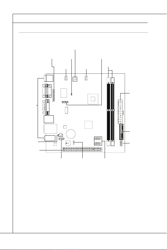
QUICK COMPONENTS GUIDE
Back Panel
DDR2
JCI1
JPWR1
JTPM1
SATA
SYSFAN1
JFP1
JUSB1~2
PCI
JPWR2
JBAT1
SYS FAN2
JLPT1
JAUD1
JSP1
MS-7618 Mainboard
▍
QUICK COMPONENTS GUIDE
JLPT1, En-12
SYSFAN2,
En-10
Back Panel,
En-8
JSP1, En-13
PCI, En-15
JAUD1, En-11
JPWR2, En-7
JCI1, En-9
SYSFAN1, En-10
JBAT1, En-14
JTPM1, En-12
DDR2, En-5
JUSB1~2, En-11
JPWR1, En-7
SATA, En-9
JFP1, En-10
En-4
Page 15

English
MEMORY
DDR2
240-pin, 1.8V
64x2=128 pin
56x2=112 pin
Memory Population Rule
1
2
Important
DIMM1 fi rst
MEMORY
These DIMM slots are used for installing memory modules. For more information on
compatible components, please visit
DDR2
240-pin, 1.8V
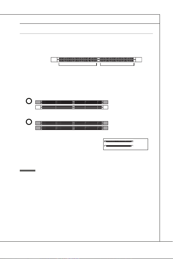
Memory Population Rule
Please refer to the following illustrations for memory population rules.
1
DIMM1
2
DIMM1
http://www.msi.com/index.php?func=testreport
64x2=128 pin
56x2=112 pin
DIMM2
DIMM2
Important
DDR2 memory modules are not interchangeable with DDR and the DDR2 standard
•
is not backwards compatible. You should always install DDR2 memory modules in
the DDR2 DIMM slots.
To enable successful system boot-up, always insert the memory modules into the
•
DIMM1 fi rst.
•
Due to the chipset resource deployment, the system density will only be detected up
to 3+GB (not full 4GB) when each DIMM is installed with a 2GB memory module.
Installed
Empty
En-5
Page 16
MS-7618 Mainboard
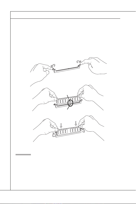
Installing Memory Modules
Important
MS-7618 Mainboard
▍
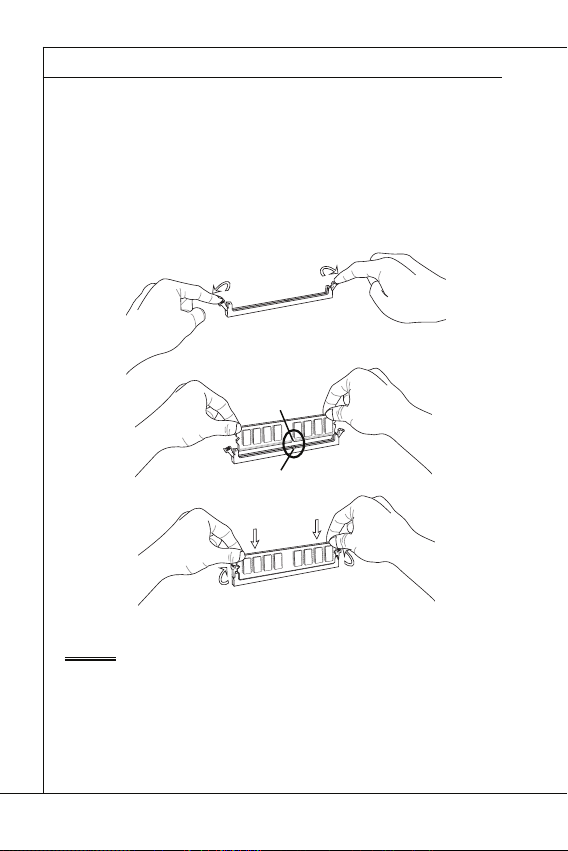
Installing Memory Modules
The memory module has only one notch on the center and will only fi t in the right
1.
orientation.
Insert the memory module vertically into the DIMM slot. Then push it in until the
2.
golden fi nger on the memory module is deeply inserted in the DIMM slot. The plastic
clip at each side of the DIMM slot will automatically close when the memory module
is properly seated.
Manually check if the memory module has been locked in place by the DIMM slot
3.
clips at the sides.
Notch
Volt
Important
You can barely see the golden fi nger if the memory module is properly inserted in the
DIMM slot.
En-6
Page 17
English
POWER SUPPLY
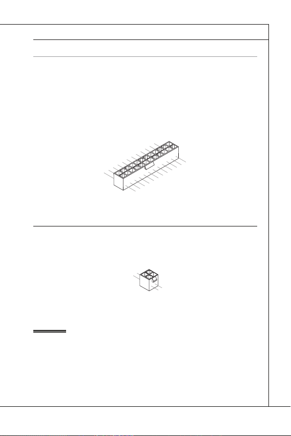
ATX 24-pin Power Connector: JPWR1
V
1
ATX 4-pin Power Connector: JPWR2
V
1
Important
POWER SUPPLY
ATX 24-pin Power Connector: JPWR1
This connector allows you to connect an ATX 24-pin power supply. To connect the ATX
24-pin power supply, make sure the plug of the power supply is inserted in the proper
orientation and the pins are aligned. Then push down the power supply fi rmly into the
connector.
You may use the 20-pin ATX power supply as you like. If you’d like to use the 20-pin
ATX power supply, please plug your power supply along with pin 1 & pin 13.
2.+3.3V
11.+12V
10.+12V
9.5VSB
8.PWR OK
7.Ground
6.+5V
5.Ground
4.+5V
3.Ground
2.+3.3V
1.+3.3V
17.Ground
16.PS-ON#
15.Ground
14.-12V
13.+3.3
ATX 4-pin Power Connector: JPWR2
This connector is used to provide the power output to the CPU.
.Ground
2.Ground
Important
Make sure that all the connectors are connected to proper ATX power supplies to
•
ensure stable operation of the mainboard.
Power supply of 350 watts (and above) is highly recommended for system stability.
•
22.+5V
21.+5V
20.Res
19.Ground
18.Ground
3.+12V
4.+12
24.Ground
23.+5V
En-7
Page 18
MS-7618 Mainboard
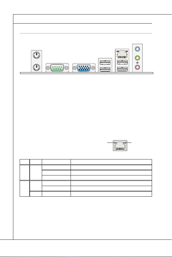
BACK PANEL
Mouse/Keyboard
Serial Port
VGA Port
USB Port
LAN
LED
Color
LED State
Condition
Audio Ports
Mouse
Line-In
USB Port
Keyboard
VGA Port
LAN
USB Port
Serial Port
Line-Out
Mic
MS-7618 Mainboard
▍
BACK PANEL
Line-In
Mouse
Keyboard
▶
Mouse/Keyboard
The standard PS/2
▶
Serial Port
The serial port is a 16550A high speed communications port that sends/ receives 16
bytes FIFOs. You can attach a serial mouse or other serial devices directly to the connector.
▶
VGA Port
The DB15-pin female connector is provided for monitor.
▶
USB Port
The USB (Universal Serial Bus) port is for attaching USB devices such as keyboard,
mouse, or other USB-compatible devices.
▶
LAN
The standard RJ-45 LAN jack is for connection to
the Local Area Network (LAN). You can connect a
network cable to it.
LED
Color
Left Yellow Off LAN link is not established.
Right Green Off 10 Mbits/sec data rate is selected.
Orange On 1000 Mbits/sec data rate is selected.
▶
Audio Ports
These audio connectors are used for audio devices. It is easy to diff erentiate between
audio eff ects according to the color of audio jacks.
■
Line-In (Blue) - Line In is used for external CD player, tapeplayer or other audio
devices.
■
Line-Out (Green) - Line Out is a connector for speakers or headphones.
■
Mic (Pink) - Mic is a connector for microphones.
Serial Port
®
mouse/keyboard DIN connector is for a PS/2® mouse/keyboard.
LED State
On(Steady state) LAN link is established.
On(brighter & pulsing) The computer is communicating with another computer on the LAN.
On 100 Mbits/sec data rate is selected.
VGA Port
Condition
USB Port
Yellow Green/ Orange
LAN
USB Port
Line-Out
Mic
En-8
Page 19

English
CONNECTORS
Serial ATA Connector: SATA1~2
F
l
o
p
p
y
D
M
S
I
F
l
o
p
p
y
D
M
S
I
K
d
k
l
k
d
k
f
k
k
k
f
d
k
k
l
d
d
f
k
k
k
s
d
d
f
d
d
f
a
s
d
k
a
d
f
-
d
d
f
d
d
a
d
d
f
d
f
d
d
d
d
d
f
a
d
f
a
d
k
j
a
s
j
d
k
d
f
d
f
a
s
d
d
d
f
f
a
s
d
f
d
d
d
d
d
d
d
f
d
a
s
f
d
a
s
a
s
d
f
a
s
d
a
s
d
a
s
d
d
d
d
d
d
d
f
a
s
a
s
d
f
s
d
f
f
s
d
f
a
d
f
f
f
a
s
d
f
f
f
d
f
Important
Chassis Intrusion Connector: JCI1
U
d
CONNECTORS
Serial ATA Connector: SATA1~2
This connector is a high-speed Serial ATA interface port. Each connector can connect
to one Serial ATA device.
l
k
k
d
f
k
k
f
d
k
f
d
d
f
k
d
d
f
d
f
k
d
d
d
s
l
a
d
k
d
f
k
-
d
s
d
k
a
d
f
k
K
f
d
f
d
d
a
d
d
f
d
d
k
d
d
d
f
d
k
d
d
s
d
d
f
a
d
j
f
s
d
d
d
f
a
d
s
j
a
a
d
s
s
k
d
a
a
f
a
d
f
f
s
d
d
a
s
d
a
f
f
d
d
d
d
s
d
f
a
d
d
d
f
s
d
s
d
f
d
a
f
f
f
d
f
d
s
s
d
f
a
s
d
a
s
f
f
a
f
d
a
D
y
p
l
p
k
k
o
d
f
l
k
k
f
k
F
I
d
f
d
d
f
k
d
S
f
d
d
f
k
d
d
d
l
a
d
s
f
k
k
d
-
d
s
d
k
M
f
K
a
d
k
f
d
d
f
d
d
d
d
a
f
k
d
d
d
d
f
d
d
k
d
s
d
d
j
f
a
d
f
d
d
s
a
d
d
f
j
s
a
d
a
k
s
s
a
d
a
f
a
d
f
f
s
d
a
d
D
s
d
f
a
d
f
d
d
y
d
s
f
d
a
f
d
d
d
p
s
d
s
d
f
f
f
d
a
f
d
p
f
d
s
s
d
f
a
s
o
d
a
s
f
l
f
a
f
d
F
I
a
S
D
M
y
p
p
o
l
F
I
S
M
Important
Please do not fold the Serial ATA cable into 90-degree angle. Otherwise, data loss may
occur during transmission.
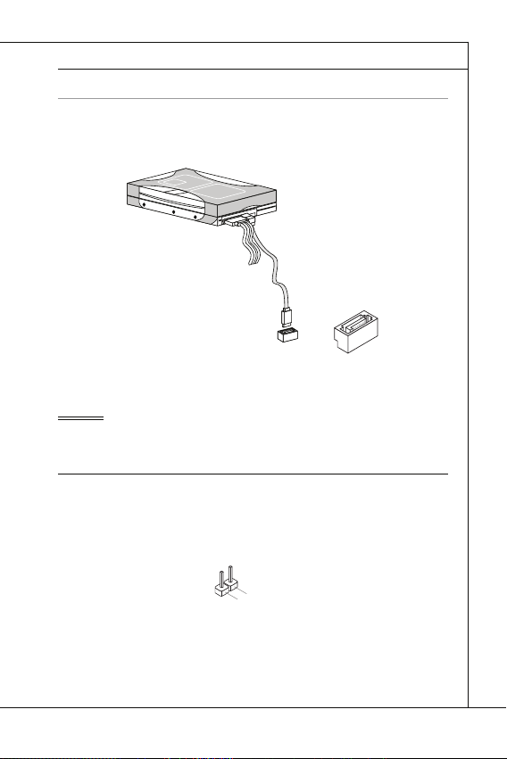
Chassis Intrusion Connector: JCI1
This connector connects to the chassis intrusion switch cable. If the chassis is opened,
the chassis intrusion mechanism will be activated. The system will record this status
and show a warning message on the screen. To clear the warning, you must enter the
BIOS utility and clear the record.
2
.
G
1
r
.
C
o
u
I
N
n
T
R
En-9
Page 20

MS-7618 Mainboard
Fan Power Connectors: SYSFAN1~2
r
Front Panel Connectors: JFP1
h
D
MS-7618 Mainboard
▍
Fan Power Connectors: SYSFAN1~2
The fan power connectors support system cooling fan with +12V. When connecting the
wire to the connectors, always note that the red wire is the positive and should be connected to the +12V; the black wire is Ground and should be connected to GND. If the
mainboard has a System Hardware Monitor chipset on-board, you must use a specially
designed fan with speed sensor to take advantage of the CPU fan control.
1
.
2
G
.
r
+
3
o
1
.
u
S
2
n
e
V
d
n
s
o
Front Panel Connectors: JFP1
The connector is for electrical connection to the front panel switches and LEDs. The
JFP1 is compliant with Intel
®
Front Panel I/O Connectivity Design Guide.
Power Switch
Power LED
10.NoPin
4.-
2.+
8.-
6.+
7.+
5.-
3.-
1.+
HDD LE
9.Reserv ed
Reset Switc
En-10
Page 21
Front USB Connector: JUSB1 / JUSB2
C
1
n
Important
Front Panel Audio Connector: JAUD1
1
L
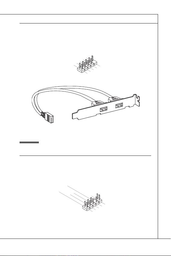
Front USB Connector: JUSB1 / JUSB2
This connector, compliant with Intel® I/O Connectivity Design Guide, is ideal for connecting high-speed USB interface peripherals such as USB HDD, digital cameras, MP3
players, printers, modems and the like.
0
.
8
U
.
S
G
6
B
r
.
o
U
4
2
.
V
O
u
S
.
U
C
C
n
B
d
S
D
B
+
D
C
-
9
.
N
7
o
.
G
5
P
.
r
U
i
o
3
u
.
S
U
1
n
B
S
.
d
D
V
B
C
+
D
-
USB 2.0 Bracket (optional)
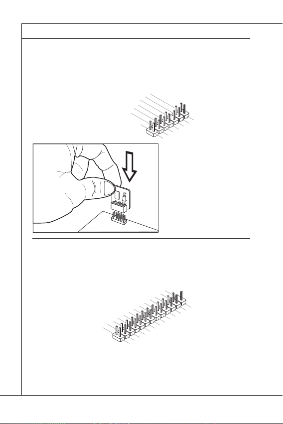
Important
Note that the pins of VCC and GND must be connected correctly to avoid possible
damage.
Front Panel Audio Connector: JAUD1
This connector allows you to connect the front panel audio and is compliant with Intel
Front Panel I/O Connectivity Design Guide.
0
.
8
H
.
e
N
6
a
o
.
d
M
4
P
.
2
.
G
r
P
I
i
P
C
n
h
R
o
D
E
o
u
n
n
e
S
d
e
t
e
E
D
c
N
e
t
i
C
t
o
e
n
E
c
#
t
i
o
n
9
.
H
7
e
.
S
5
a
E
.
d
H
3
1
.
M
N
P
.
e
M
S
h
a
E
o
I
d
C
I
C
L
n
_
P
e
S
R
h
E
o
N
n
e
D
R
English
®
En-11
Page 22
MS-7618 Mainboard
TPM Module connector: JTPM1
1
2
0
3
Parallel Port Header: JLPT1
MS-7618 Mainboard
▍
TPM Module connector: JTPM1
This connector connects to a TPM (Trusted Platform Module) module (optional).
Please refer to the TPM security platform manual for more details and usages.
4
1
.
G
2
1
.
r
G
o
0
u
.
r
8
N
o
n
.
u
o
d
5
6
n
V
P
.
S
4
.
3
.
3
.
3
V
S
t
a
Parallel Port Header: JLPT1
This connector is used to connect an optional parallel port bracket. The parallel port is a
standard printer port that supports Enhanced Parallel Port (EPP) and Extended Capabilities Parallel Port (ECP) mode.
1
6
1
4
1
.
G
2
1
.
G
0
.
r
8
G
o
.
u
r
L
6
o
P
.
u
P
T
4
2
.
A
n
I
_
.
N
E
S
I
R
T
L
R
I
#
F
N
#
D
#
d
i
P
n
e
o
r
i
w
a
e
l
V
I
r
R
P
Q
o
w
e
n
r
d
b
y
p
o
w
e
r
1
2
6
2
.
N
4
2
.
o
G
2
P
2
r
.
G
o
0
1
8
.
G
.
G
r
o
u
r
o
u
n
d
n
d
d
#
i
n
u
.
r
G
o
n
u
d
r
o
n
u
d
r
o
n
u
d
n
d
n
d
1
3
1
1
.
9
P
.
P
7
R
.
P
5
N
R
.
P
3
N
R
.
P
1
D
N
R
.
2
D
R
N
S
1
D
T
0
B
#
1
3
1
.
L
1
P
.
9
L
C
.
P
L
7
5
.
L
3
.
L
P
.
L
C
P
C
C
1
9
1
7
1
.
P
5
.
P
R
.
P
N
R
N
R
D
N
D
D
4
3
F
C
P
.
L
P
R
l
o
2
.
A
R
D
5
r
C
a
a
P
m
d
a
C
d
d
C
a
d
e
s
e
c
k
2
2
3
.
1
.
B
U
C
K
N
D
7
6
e
r
a
d
e
d
r
s
e
d
s
s
r
&
s
e
d
s
r
t
5
.
P
E
S
#
&
e
S
Y
d
s
a
d
s
&
s
L
C
t
a
a
d
t
&
T
a
p
a
d
i
p
t
n
a
a
i
n
t
p
a
2
i
n
p
1
i
n
En-12
Page 23
English
S/PDIF-Out Connector: JSP1
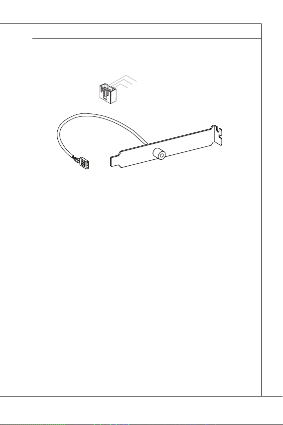
S/PDIF-Out Connector: JSP1
This connector is used to connect S/PDIF (Sony & Philips Digital Interconnect Format)
interface for digital audio transmission.
3
.
G
2
.
r
S
o
1
P
u
.
V
n
D
d
C
I
F
C
S/PDIF Bracket (Optional)
En-13
Page 24

MS-7618 Mainboard
JUMPERS
Clear CMOS Jumper: JBAT1
JBAT1
1 11
Important
MS-7618 Mainboard
▍
JUMPERS
Clear CMOS Jumper: JBAT1
There is a CMOS RAM onboard that has a power supply from an external battery to keep
the data of system confi guration. With the CMOS RAM, the system can automatically
boot OS every time it is turned on. If you want to clear the system confi guration, set the
jumper to clear data.
JBAT1 Keep Data Clear Data
Important
You can clear CMOS by shorting 2-3 pin while the system is off . Then return to 12 pin position. Avoid clearing the CMOS while the system is on; it will damage the
mainboard.
En-14
Page 25
English
SLOTS
PCI (Peripheral Component Interconnect) Slot
Important
PCI Interrupt Request Routing
Order1 Order2 Order3 Order4
SLOTS
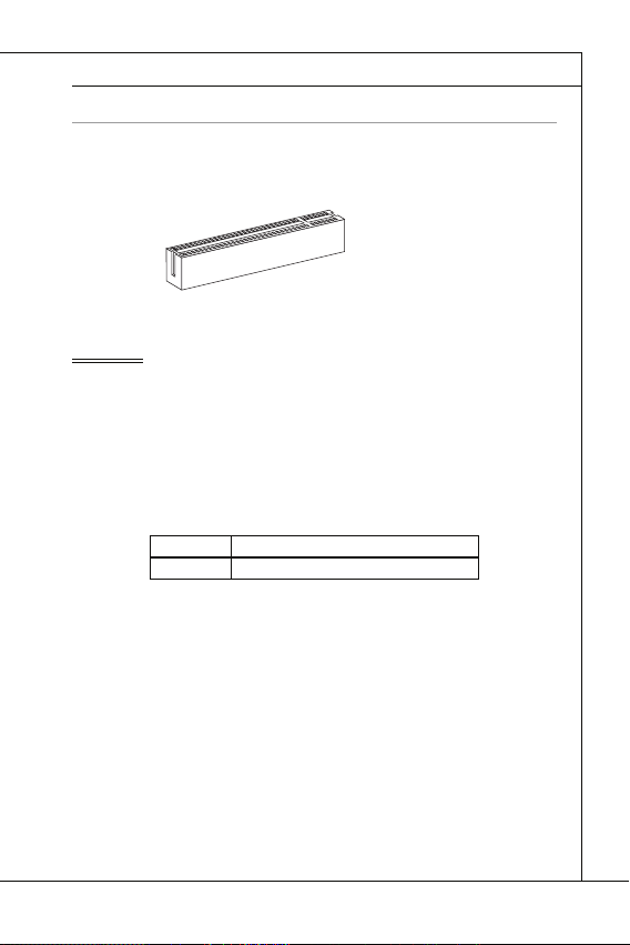
PCI (Peripheral Component Interconnect) Slot
The PCI slot supports LAN card, SCSI card, USB card, and other add-on cards that
comply with PCI specifi cations.
32-bit PCI Slot
Important
When adding or removing expansion cards, make sure that you unplug the power supply fi rst. Meanwhile, read the documentation for the expansion card to confi gure any
necessary hardware or software settings for the expansion card, such as jumpers,
switches or BIOS confi guration.
PCI Interrupt Request Routing
The IRQ, acronym of interrupt request line and pronounced I-R-Q, are hardware lines
over which devices can send interrupt signals to the microprocessor. The PCI IRQ pins
are typically connected to the PCI bus pins as follows:
PCI Slot1 INT B# INT C# INT D# INT A#
Order1 Order2 Order3 Order4
En-15
Page 26

MS-7618 Mainboard
BIOS SETUP
Important
MS-7618 Mainboard
▍
BIOS SETUP
This chapter provides basic information on the BIOS Setup program and allows you to
confi gure the system for optimum use. You may need to run the Setup program when:
An error message appears on the screen during the system booting up, and
■
requests you to run BIOS SETUP.
You want to change the default settings for customized features.
■
Important
The items under each BIOS category described in this chapter are under continuous
•
update for better system performance. Therefore, the description may be slightly different from the latest BIOS and should be held for reference only.
Upon boot-up, the 1st line appearing after the memory count is the BIOS version. It is
•
usually in the format:
1st digit refers to BIOS maker as A = AMI, W = AWARD, and P = PHOENIX.
2nd - 5th digit refers to the model number.
6th digit refers to the chipset as I = Intel, N = NVIDIA, A = AMD and V = VIA.
7th - 8th digit refers to the customer as MS = all standard customers.
V1.0 refers to the BIOS version.
020110 refers to the date this BIOS was released.
En-16
A7618IMS V1.0 020110 where:
Page 27

English
Entering Setup
Press DEL to enter SETUP
Getting Help
Main Menu
Sub-Menu
General Help <F1>
Entering Setup
Power on the computer and the system will start POST (Power On Self Test) process.
When the message below appears on the screen, press <DEL> key to enter Setup.
Press DEL to enter SETUP
If the message disappears before you respond and you still wish to enter Setup, restart
the system by turning it OFF and On or pressing the RESET button. You may also restart the system by simultaneously pressing <Ctrl>, <Alt>, and <Delete> keys.
Getting Help
After entering the Setup menu, the fi rst menu you will see is the Main Menu.
Main Menu
The main menu lists the setup functions you can make changes to. You can use the
arrow keys ( ↑↓ ) to select the item. The on-line description of the highlighted setup
function is displayed at the bottom of the screen.
Sub-Menu
If you fi nd a right pointer symbol appears to the left of certain fi elds that means a sub-
menu can be launched from this fi eld. A sub-menu contains additional options for a
fi eld parameter. You can use arrow keys ( ↑↓ ) to highlight the fi eld and press <Enter>
to call up the sub-menu. Then you can use the control keys to enter values and move
from fi eld to fi eld within a sub-menu. If you want to return to the main menu, just press
the <Esc >.
General Help <F1>
The BIOS setup program provides a General Help screen. You can call up this screen
from any menu by simply pressing <F1>. The Help screen lists the appropriate keys to
use and the possible selections for the highlighted item. Press <Esc> to exit the Help
screen.
En-17
Page 28

MS-7618 Mainboard
The Main Menu
Standard CMOS Features
Advanced BIOS Features
Integrated Peripherals
Power Management Setup
H/W Monitor
BIOS Setting Password
Cell Menu
M-Flash
MS-7618 Mainboard
▍
The Main Menu
Once you enter BIOS CMOS Setup Utility, the Main Menu will appear on the screen.
The Main Menu allows you to select from the setup functions and two exit choices.
Use arrow keys to select among the items and press <Enter> to accept or enter the
sub-menu.
▶
Standard CMOS Features
Use this menu for basic system confi gurations, such as time, date etc.
▶
Advanced BIOS Features
Use this menu to setup the items of the BIOS special enhanced features.
▶
Integrated Peripherals
Use this menu to specify your settings for integrated peripherals.
▶
Power Management Setup
Use this menu to specify your settings for power management.
▶
H/W Monitor
This entry shows your PC health status.
▶
BIOS Setting Password
Use this menu to set the password for BIOS.
▶
Cell Menu
Use this menu to specify your settings for frequency/voltage control and overclocking.
▶
M-Flash
Use this menu to read/ fl ash (or backup) the BIOS from (to) storage drive (FAT/ FAT32
format only).
En-18
Page 29

English
Load Fail-Safe Defaults
Load Optimized Defaults
Save & Exit Setup
Exit Without Saving
Load Fail-Safe Defaults
▶
Use this menu to load the default values set by the BIOS vendor for stable system
performance.
▶
Load Optimized Defaults
Use this menu to load the default values set by the mainboard manufacturer specifi cally
for optimal performance of the mainboard.
▶
Save & Exit Setup
Save changes to CMOS and exit setup.
Exit Without Saving
▶
Abandon all changes and exit setup.
En-19
Page 30
MS-7618 Mainboard
Important
MS-7618 Mainboard
▍
When enter the BIOS Setup utility, follow the processes below for general use.
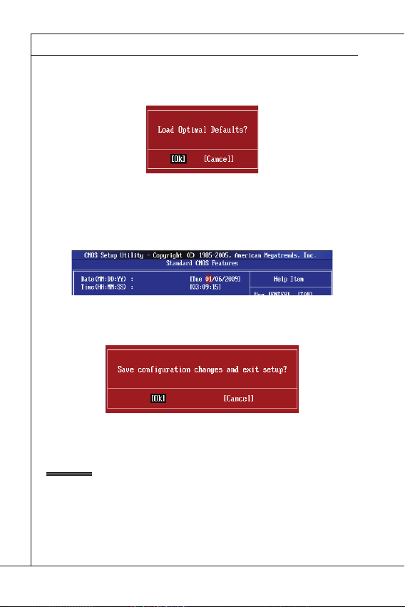
Load Optimized Defaults : Use control keys (↑↓) to highlight the Load Optimized
1.
Defaults fi eld and press <Enter> , a message as below appears:
Select [Ok] and press Enter to load the default settings for optimal system performance.
Setup Date/ Time : Select the Standard CMOS Features and press <Enter> to enter
2.
the Standard CMOS Features-menu. Adjust the Date, Time fi elds.
Save & Exit Setup : Use control keys (↑↓) to highlight the Save & Exit Setup fi eld
3.
and press <Enter> , a message as below appears:
Select [Ok] and press Enter to save the confi gurations and exit BIOS Setup utility.
Important
The confi guration above are for general use only. If you need the detailed settings of
BIOS, please see the English manual on MSI website.
En-20
Page 31

English
Important
Current CPU / DRAM Frequency
CPU Specifi cations
CPU Technology Support
CPU Feature
Hyper-Threading Function
4.
Cell Menu Introduction : This menu is for advanced user who want to overclock the
mainboard.
Important
Change these settings only if you are familiar with the chipset.
▶
Current CPU / DRAM Frequency
These items show the current frequencies of CPU and Memory. Read-only.
▶
CPU Specifi cations
Press <Enter> to enter the sub-menu. This submenu shows the information of installed
CPU.
▶
CPU Technology Support
Press <Enter> to enter the sub-menu. In this sub-menu, it shows the installed CPU
technologies. Read only.
▶
CPU Feature
Press <Enter> to enter the sub-menu.
▶
Hyper-Threading Function
The processor uses Hyper-Threading technology to increase transaction rates and
reduces end-user response times. The technology treats the two cores inside the
processor as two logical processors that can execute instructions simultaneously. In
this way, the system performance is highly improved. If you disable the function, the
processor will use only one core to execute the instructions. Please disable this item
if your operating system doesn’t support HT Function, or unreliability and instability
may occur.
En-21
Page 32

MS-7618 Mainboard
Important
Execute Bit Support
Set Limit CPUID MaxVal to 3
Memory-Z
DIMM1~2 Memory SPD Information
Advance DRAM Confi guration
DRAM Timing Mode
CAS Latency (CL)
MS-7618 Mainboard
▍
Important
Enabling the functionality of Hyper-Threading Technology for your computer system
requires ALL of the following platform Components:
•
CPU: An Intel
•
Chipset: An Intel
•
BIOS: A BIOS that supports HT Technology and has it enabled;
•
OS: An operating system that supports HT Technology.
®
Processor with HT Technology;
®
Chipset that supports HT Technology;
For more information on Hyper-threading Technology, go to:
http://www.intel.com/products/ht/hyperthreading_more.htm
Execute Bit Support
▶
Intel’s Execute Disable Bit functionality can prevent certain classes of malicious
“buff er overfl ow” attacks when combined with a supporting operating system. This
functionality allows the processor to classify areas in memory by where application
code can execute and where it cannot. When a malicious worm attempts to insert
code in the buff er, the processor disables code execution, preventing damage or
worm propagation.
Set Limit CPUID MaxVal to 3
▶
The Max CPUID Value Limit is designed limit the listed speed of the processor to
older operating systems.
▶
Memory-Z
Press <Enter> to enter the sub-menu.
▶
DIMM1~2 Memory SPD Information
Press <Enter> to enter the sub-menu. The sub-menu displays the informations of
installed memory.
▶
Advance DRAM Confi guration
When the DRAM Timing Mode is set to [Manual], this sub-menu will available. Press
<Enter> to enter the sub-menu.
▶
DRAM Timing Mode
Select whether DRAM timing is controlled by the SPD (Serial Presence Detect) EEPROM on the DRAM module. Setting to [Auto] enables DRAM timings and the following “Advance DRAM Confi guration” sub-menu to be determined by BIOS based
on the confi gurations on the SPD. Selecting [Manual] allows users to confi gure the
DRAM timings and the following related “Advance DRAM Confi guration” sub-menu
manually.
▶
CAS Latency (CL)
This controls the CAS latency, which determines the timing delay (in clock cycles)
before SDRAM starts a read command after receiving it.
En-22
Page 33

English
tRCD
tRP
tRAS
Auto Disable DRAM/PCI Frequency
CPU VTT (V)/ DRAM Voltage (V)/ CPU NB (V)/ SB 1.50 (V)
Spread Spectrum
Important
tRCD
▶
When DRAM is refreshed, both rows and columns are addressed separately. This
setup item allows you to determine the timing of the transition from RAS (row address strobe) to CAS (column address strobe). The less the clock cycles, the faster
the DRAM performance.
tRP
▶
This setting controls the number of cycles for Row Address Strobe (RAS) to be
allowed to precharge. If insuffi cient time is allowed for the RAS to accumulate its
charge before DRAM refresh, refresh may be incomplete and DRAM may fail to
retain data. This item applies only when synchronous DRAM is installed in the system.
▶
tRAS
This setting determines the time RAS takes to read from and write to memory cell.
▶
Auto Disable DRAM/PCI Frequency
When set to [Enabled], the system will remove (turn off ) clocks from empty DIMM/ PCI
slots to minimize the electromagnetic interference (EMI).
▶
CPU VTT (V)/ DRAM Voltage (V)/ CPU NB (V)/ SB 1.50 (V)
These items are used to adjust the voltage of CPU, DRAM, CPU NB and SB.
Spread Spectrum
▶
When the mainboard’s clock generator pulses, the extreme values (spikes) of the pulses
create EMI (Electromagnetic Interference). The Spread Spectrum function reduces the
EMI generated by modulating the pulses so that the spikes of the pulses are reduced
to fl atter curves.
Important
•
If you do not have any EMI problem, leave the setting at [Disabled] for optimal system
stability and performance. But if you are plagued by EMI, select the value of Spread
Spectrum for EMI reduction.
•
The greater the Spread Spectrum value is, the greater the EMI is reduced, and the
system will become less stable. For the most suitable Spread Spectrum value, please
consult your local EMI regulation.
Remember to disable Spread Spectrum if you are overclocking because even a slight
•
jitter can introduce a temporary boost in clock speed which may just cause your overclocked processor to lock up.
En-23
Page 34

MS-7618 Mainboard
SOFTWARE INFORMATION
Important
MS-7618 Mainboard
▍
SOFTWARE INFORMATION
Take out the Driver/Utility DVD that is included in the mainboard package, and place
it into the DVD-ROM drive. The installation will auto-run, simply click the driver or utility and follow the pop-up screen to complete the installation. The Driver/Utility DVD
contains the:
Driver menu : The Driver menu shows the available drivers. Install the driver by
your desire and to activate the device.
Utility menu : The Utility menu shows the software applications that the mainboard
supports.
WebSite menu : The WebSite menu shows the necessary websites.
-
Important
Please visit the MSI website to get the latest drivers and BIOS for better system performance.
En-24
Page 35

Deutsch
Wind Board
D510/ D410
Serie
Wind Board
D510/ D410
Serie
Deutsch
Europe version
Page 36

MS-7618 Mainboard
SPEZIFICATIONEN
PProzessoren
Die extremalen Taktfrequenz des Basetakts
Chipsatz
Speicher
LAN
Audio
SATA
Anschlüsse
MS-7618 Mainboard
▍
SPEZIFICATIONEN
rozessoren
■
Unterstützt Intel® Atom CPU D510/ D410
Die extremalen Taktfrequenz des Basetakts
■
100 MHZ
Chipsatz
®
■
Intel
NM10 Chipsatz
Speicher
■
DDR2 800 SDRAM (max. 4GB)
■
2 DDR2 DIMMs (240Pin / 1,8V), Einkanal
*(Weitere Informationen zu kompatiblen Speichermodulen fi nden Sie unter
http://www.msi.com/index.php?func=testreport)
LAN
■
Unterstützt Realtek® RTL8103EL 10/100 Mb/s
■
Unterstützt Realtek
■
Unterstützt ACPI Stromsparfunktion
Audio
■
Onboard Soundchip Realtek® ALC888S
■
6-Kanal Audio-Ausgang
SATA
■
2 SATA 3 Gb/s Anschlüsse über Intel® NM10
Anschlüsse
■
Hintere Ein-/ und Ausgänge
‑
1 PS/2 Mausanschluss
‑
1 PS/2 Tastaturanschlus
‑
1 Serieller Anschluss
‑
1 VGA Anschluss
‑
4 USB 2.0 Anschlüsse
‑
1 RJ-45 Anschluss
‑
3 Audiobuchsen
■
On-Board Stiftleiste/ Anschlüsse
‑
2 USB 2.0 Stiftleisten
‑
1 Parallele Stiftleiste
‑
1 Audio Stiftleiste für Gehäuse Audio Ein-/ Ausgänge
‑
1 S/PDIF-Ausgang Stiftleiste
‑
1 Gehäusekontaktschalter
‑
1 TPM Stiftleiste
®
RTL8111DL 10/100/1000 Mb/s (optional)
De-2
Page 37

Deutsch
SSteckplätze
Form Faktor
MMontage
teckplätze
1 PCI-Steckplatz
■
Unterstützt 3,3V/ 5V PCI Bus Interface
■
Form Faktor
Mini-ITX (17,0cm X 17,0cm)
■
ontage
4 Montagebohrungen
■
Wenn Sie für Bestellungen von Zubehör Teilenummern benötigen, fi nden Sie diese auf
unserer Produktseite unter http://www.msi.com/index.php
De-3
Page 38

MS-7618 Mainboard
KOMPONENTEN-ÜBERSICHT
Rü ckt afe l
DDR2
JCI1
JPWR1
JTPM1
SATA
SYSFAN1
JFP1
JUSB1~2
PCI
JPWR2
JBAT1
SYS FAN2
JLPT1
JAUD1
JSP1
MS-7618 Mainboard
▍
KOMPONENTEN-ÜBERSICHT
JLPT1, De-12
SYSFAN2,
De-10
Rücktafel,
De-8
JSP1, De-13
PCI, De-15
JAUD1, De-11
JPWR2, De-7
JCI1, De-9
SYSFAN1, De-10
JBAT1, De-14
JTPM1, De-12
DDR2, De-5
JUSB1~2, De-11
JPWR1, De-7
SATA, De-9
JFP1, De-10
De-4
Page 39
Deutsch
SPEICHER
DDR2
240-polig, 1,8V
64x2=128 Pole
56x2=112 Pole
Hinweise für den Einsatz von Speichermodulen
1
2
Wichtig
DIMM1 zu
erst
SPEICHER
Diese DIMM-Steckplätze nehmen Arbeitsspeichermodule auf. Die neusten Informationen über kompatible Bauteile fi nden Sie unter
php?func=testreport
DDR2
240-polig, 1,8V
Hinweise für den Einsatz von Speichermodulen
Bitte beachten Sie die folgenden Abbildungen zum Speichereinbau.
1
DIMM1
2
DIMM1
64x2=128 Pole
http://www.msi.com/index.
56x2=112 Pole
DIMM2
DIMM2
Wichtig
DDR2 und DDR können nicht untereinander getauscht werden und der Standard
•
DDR2 ist nicht abwärtskompatibel. Installieren Sie DDR2 Speichermodule stets in
DDR2 DIMM Slots.
Um einen sicheren Systemstart (besonders für Lynnfi eld CPU) zu gewährleisten,
•
bestücken Sie immer
Aufgrund der Chipsatzressourcennutzung wird nur eine Systemdichte bis 3+GB
•
(nicht volle 4GB) erkannt, wenn jeder DIMM Slot mit einem 2GB Speichermodul besetzt wird.
DIMM1 zu
erst.
installiert
Installed
leer
Empty
De-5
Page 40
MS-7618 Mainboard
Vorgehensweise beim Einbau von Speicher Modulen
Wichtig
MS-7618 Mainboard
▍
Vorgehensweise beim Einbau von Speicher Modulen
Die Speichermodulen haben nur eine Kerbe in der Mitte des Moduls. Sie passen
1.
nur in einer Richtung in den Sockel.
Stecken Sie das Arbeitsspeichermodul senkrecht in den DIMM-Steckplatz ein.
2.
Drücken Sie anschließnd das Arbeitsspeichermodul nach unten, bis die Kontaktseite richtig tief in dem DIMM-Steckplatz sitzt. Der Kunststoff bügel an jedem Ende
des DIMM-Steckplatzes schnappt automatisch ein, wenn das Arbeitsspeichermodul
richtig eingesetzt ist.
Prüfen Sie von Hand, ob das Arbeitsspeichermodul von den seitlichen Bügeln am
3.
DIMM-Steckplatz richtig gehalten wird.
Notch
Kerbe
Wichtig
Die goldenen Kontakte sind kaum zu sehen, wenn das Arbeitsspeichermodul richtig im
DIMM-Steckplatz sitzt.
De-6
Page 41

Deutsch
STROMVERSORGUNG
ATX 24-poliger Stromanschluss: JPWR1
V
1
ATX 4-poliger Stromanschluss: JPWR2
V
1
Wichtig
STROMVERSORGUNG
ATX 24-poliger Stromanschluss: JPWR1
Mit diesem Anschluss verbinden Sie den ATX 24-poligen Anschluss des Netzteils.
Achten Sie bei dem Verbinden des ATX 24-poligen Stromanschlusses darauf, dass
der Anschluss des Netzteils richtig auf den Anschluss an der Hauptplatine ausgerichtet
ist. Drücken Sie dann den Anschluss des Netzteils fest nach unten, um eine richtige
Verbindung zu gewährleisten.
Sie können auch den 20-poligen ATX-Stromanschluss des Netzteils verwenden. In diesem Fall muss eine Ecke des 20-poligen ATX-Stromanschlusses des Netzteils auf den
Pol 1 bzw. Pol 13 des Anschlusses an der Hauptplatine ausgerichtet werden.
2.+3.3V
11.+12V
10.+12V
9.5VSB
8.PWR OK
7.Ground
6.+5V
5.Ground
4.+5V
3.Ground
2.+3.3V
1.+3.3V
17.Ground
16.PS-ON#
15.Ground
14.-12V
13.+3.3
ATX 4-poliger Stromanschluss: JPWR2
Dieser Stromanschluss wird verwendet, um die CPU mit Strom zu versorgen.
.Ground
2.Ground
22.+5V
21.+5V
20.Res
19.Ground
18.Ground
3.+12V
4.+12
24.Ground
23.+5V
Wichtig
Stellen Sie sicher, dass diese Anschlüsse mit den richtigen Anschlüssen des Netz-
•
teils verbunden werden, um einen stabilen Betrieb der Hauptplatine sicherzustellen.
Für die Systemstabilität ist ein Netzteil mit 350 Watt (oder noch mehr) empfe-
•
hlenswert.
De-7
Page 42

MS-7618 Mainboard
RÜCKTAFEL
Maus/Tastatur
Serieller Anschluss
VGA Anschluss
USB Anschluss
LAN
LED
Farbe
LED Status
Zustand
Audioanschlüsse
Maus
Line-In
USB Anschluss
Tastatur
VGA Anschluss
LAN
USB Anschluss
Serieler Anschluss
Line-Out
Mic
MS-7618 Mainboard
▍
RÜCKTAFEL
Line-In
Maus
USB Anschluss
Serieler Anschluss
Tastatur
▶
Maus/Tastatur
Die Standard PS/2
▶
Serieller Anschluss
Es handelt sich um eine 16550A Kommunikationsschnittstelle, die 16 Bytes FIFOs
senden/empfängt. Hier lässt sich eine serielle Maus oder andere serielle Geräte direkt
anschließen.
▶
VGA Anschluss
Die DB 15-Pin Buchse dient zum Anschluss eines VGA Monitors.
▶
USB Anschluss
Dieser USB (Universal Serial Bus) Anschluss zum direkten Anschluss von USB-
Geräten, wie etwa Tastatur, Maus oder weiterer USB-kompatibler Geräte.
▶
LAN
Die Standard RJ-45 Buchse ist für Anschlus zum
an ein Lokales Netzwerk (Local Area Network LAN). Hier kann ein Netzwerkkabel angeschlossen
werden.
LED
Links Gelb Aus Keine Verbindung mit dem LAN.
Rechts Grün Aus Gewählte Datenrate 10 MBit/s.
Audioanschlüsse
▶
Diese Audioanschlüsse dienen zur Verbindung mit Audiogeräten. Durch die Farben
erkennen Sie die unterschiedlichen Funktionen der Audioanschlüsse.
■
■
■
®
Maus/Tastatur Stecker Mini DIN ist für eine PS/2® Maus/Tastatur.
Farbe
LED Status
An (Dauerleuchten) Verbindung mit dem LAN.
An (heller & pulsierend) Der Computer kommuniziert mit einem anderen Rechner im LAN.
An Gewählte Datenrate 100 MBit/s.
Orange An Gewählte Datenrate 1000 MBit/s.
Line-In (Blau) - Der Anschluss “Line In” kann einen externen CDPlayer,Tapeplayer oder ein sonstiges Audiogerät aufnehmen.
Line-Out (Grün) - An den Anschluss “Line Out” können Sie Lautsprecher oder
Kopfhörer anschließen.
Mikrofon (Rosa) - Der Anschluss “Mic” nimmt ein Mikrofon auf.
VGA Anschluss
Zustand
Gelb Grün/ Orange
LAN
USB Anschluss
Line-Out
Mic
De-8
Page 43
Deutsch
ANSCHLÜSSEN
Serial ATA Anschluss: SATA1~2
F
l
o
p
p
y
D
M
S
I
F
l
o
p
p
y
D
M
S
I
K
d
k
l
k
d
k
f
k
k
k
f
d
k
k
l
d
d
f
k
k
k
s
d
d
f
d
d
f
a
s
d
k
a
d
f
-
d
d
f
d
d
a
d
d
f
d
f
d
d
d
d
d
f
a
d
f
a
d
k
j
a
s
j
d
k
d
f
d
f
a
s
d
d
d
f
f
a
s
d
f
d
d
d
d
d
d
d
f
d
a
s
f
d
a
s
a
s
d
f
a
s
d
a
s
d
a
s
d
d
d
d
d
d
d
f
a
s
a
s
d
f
s
d
f
f
s
d
f
a
d
f
f
f
a
s
d
f
f
f
d
f
Wichtig
Gehäusekontaktanschluss: JCI1
U
d
ANSCHLÜSSEN
Serial ATA Anschluss: SATA1~2
Der Anschluss ist eine Hochgeschwindigkeitsschnittstelle der Serial ATA. Pro Anschluss kann ein S-ATA Geräte angeschlossen werden.
l
k
k
d
f
k
k
f
d
k
f
d
d
f
k
d
d
f
d
f
k
d
d
d
s
l
a
d
k
d
f
k
-
d
s
d
k
a
d
f
k
K
f
d
f
d
d
a
d
d
f
d
d
k
d
d
d
f
d
k
d
d
s
d
d
f
a
d
j
f
s
d
d
d
f
a
d
s
j
a
a
d
s
s
k
d
a
a
f
a
d
f
f
s
d
d
a
s
d
a
f
f
d
d
d
d
s
d
f
a
d
d
d
f
s
d
s
d
f
d
a
f
f
f
d
f
d
s
s
d
f
a
s
d
a
s
f
f
a
f
d
a
D
y
p
l
p
k
k
o
d
f
l
k
k
f
k
F
I
d
f
d
d
f
k
d
S
f
d
d
f
k
d
d
d
l
a
d
s
f
k
k
d
-
d
s
d
k
M
f
K
a
d
k
f
d
d
f
d
d
d
d
a
f
k
d
d
d
d
f
d
d
k
d
s
d
d
j
f
a
d
f
d
d
s
a
d
d
f
j
s
a
d
a
k
s
s
a
d
a
f
a
d
f
f
s
d
a
d
D
s
d
f
a
d
f
d
d
y
d
s
f
d
a
f
d
d
d
p
s
d
s
d
f
f
f
d
a
f
d
p
f
d
s
s
d
f
a
s
o
d
a
s
f
l
f
a
f
d
F
I
a
S
D
M
y
p
p
o
l
F
I
S
M
Wichtig
Bitte falten Sie das Serial ATA Kabel nicht in einem Winkel von 90 Grad, da dies zu
Datenverlusten während der Datenübertragung führt.
Gehäusekontaktanschluss: JCI1
Dieser Anschluss wird mit einem Kontaktschalter verbunden. Wird das Gehäuse geöff net, wird der Schalter geschlossen und das System zeichnet dies auf und gibt auf dem
Bildschirm eine Warnung aus. Um die Warnmeldung zu löschen, muss das BIOS aufgerufen und die Aufzeichnung gelöscht werden.
2
.
G
1
r
.
C
o
u
I
N
n
T
R
De-9
Page 44

MS-7618 Mainboard
Stromanschlüsse für Lüfter: SYSFAN1~2
r
Frontpanel Anschlüsse: JFP1
h
D
MS-7618 Mainboard
▍
Stromanschlüsse für Lüfter: SYSFAN1~2
Die Anschlüsse unterstützen aktive Systemlüfter mit + 12V. Wenn Sie den Anschluss
herstellen, sollten Sie immer darauf achten, dass der rote Draht der positive Pol ist, und
mit +12V verbunden werden sollte. Der schwarze Draht ist der Erdkontakt und sollte mit
GND verbunden werden. Ist Ihr Mainboard mit einem Chipsatz zur Überwachung der
Systemhardware versehen, dann brauchen Sie einen speziellen Lüfter mit Tacho, um
die Vorteile der Steuerung des CPU Lüfters zu nutzen.
1
.
2
G
.
r
+
3
o
1
.
u
S
2
n
e
V
d
n
s
o
Frontpanel Anschlüsse: JFP1
Diese Anschlüsse sind für das Frontpanel. Sie dienen zum Anschluss der Schalter und
LEDs des Frontpanels. JFP1 erfüllt die Anforderungen des “Intel
nectivity Design Guide“.
Power Switch
Power LED
10.NoPin
4.-
2.+
8.-
6.+
9.Reserv ed
7.+
5.-
3.-
1.+
HDD LE
Reset Switc
®
Front Panel I/O Con-
De-10
Page 45

USB Vorderanschluss: JUSB1 / JUSB2
C
1
n
Wichtig
Audioanschluss des Frontpanels: JAUD1
1
L
USB Vorderanschluss: JUSB1 / JUSB2
Dieser Anschluss entspricht den Richtlinien des Intel® I/O Connectivity Design Guide.
Er ist bestens geeignet, Hochgeschwindigkeits- USB- Peripheriegeräte anzuschließen,
wie z.B. USB Festplattenlaufwerke, Digitalkameras, MP3-Player, Drucker, Modems und
ähnliches.
0
.
8
U
.
S
G
6
B
r
.
o
U
4
2
.
V
O
u
S
.
U
C
C
n
B
d
S
D
B
+
D
C
-
9
.
N
7
o
.
G
5
P
.
r
U
i
o
3
u
.
S
U
1
n
B
S
.
d
D
V
B
C
+
D
-
USB 2.0 Slotblech (optional)
Wichtig
Bitte beachten Sie, dass Sie die mit VCC (Stromführende Leitung) und GND (Erdleitung) bezeichneten Pins korrekt verbinden müssen, ansonsten kann es zu Schäden
kommen.
Audioanschluss des Frontpanels: JAUD1
Dieser Anschluss ermöglicht den Anschluss von Audioein und -ausgängen eines Frontpanels. Der Anschluss entspricht den Richtlinien des “ Intel
ity Design Guide”.
0
.
8
H
.
e
N
6
a
o
.
d
M
4
P
.
2
.
G
r
P
I
i
P
C
n
h
R
o
D
E
o
u
n
n
e
S
d
e
t
e
E
D
c
N
e
t
i
C
t
o
e
n
E
c
#
t
i
o
n
®
Front Panel I/O Connectiv-
9
.
H
7
e
.
S
5
E
.
H
3
N
.
e
M
S
1
a
.
I
d
M
C
P
I
R
C
L
a
d
P
h
E
o
n
_
e
S
h
E
o
N
n
e
D
R
Deutsch
De-11
Page 46

MS-7618 Mainboard
TPM Modul Anschluss: JTPM1
1
2
0
3
Parallele Schnittstelle: JLPT1
MS-7618 Mainboard
▍
TPM Modul Anschluss: JTPM1
Dieser Anschluss wird für das optionale TPM Modul (Trusted Platform Module)
(optional) verwendt. Weitere Informationen über den Einsatz des optionalen TPM
Modules entnehmen Sie bitte dem TPM Plattform Handbuch.
4
1
.
G
2
1
.
r
G
o
0
u
.
r
8
N
o
n
.
u
o
d
5
6
n
V
P
.
S
4
.
3
.
3
.
3
V
S
t
a
Parallele Schnittstelle: JLPT1
Die Parallele Schnittstelle ist eine Standard Druckerschnittstelle, die ebenso als Enhanced Parallel Port (EPP) und als Extended Capabilities Parallel Port (ECP) betrieben
werden kann.
1
6
1
4
1
.
G
2
1
.
G
0
.
r
8
G
o
.
u
r
L
6
o
P
.
u
P
T
4
2
.
A
n
I
_
.
N
E
S
I
R
T
L
R
I
#
F
N
#
D
#
d
i
P
n
e
o
r
i
w
a
e
l
V
I
r
R
P
Q
o
w
e
n
r
d
b
y
p
o
w
e
r
1
2
6
2
.
N
4
2
.
o
G
2
P
2
r
.
G
o
0
1
8
.
G
.
G
r
o
u
r
o
u
n
d
n
d
d
#
i
n
u
.
r
G
o
n
u
d
r
o
n
u
d
r
o
n
u
d
n
d
n
d
1
3
1
1
.
9
P
.
P
7
R
.
P
5
N
R
.
P
3
N
R
.
P
1
D
N
R
.
2
D
R
N
S
1
D
T
0
B
#
1
3
1
.
L
1
P
.
9
L
C
.
P
L
7
5
.
L
3
.
L
P
.
L
C
P
C
C
1
9
1
7
1
.
P
5
.
P
R
.
P
N
R
N
R
D
N
D
D
4
3
F
C
P
.
L
P
R
l
o
2
.
A
R
D
5
r
C
a
a
P
m
d
a
C
d
d
C
a
d
e
s
e
c
k
2
2
3
.
1
.
B
U
C
K
N
D
7
6
e
r
a
d
e
d
r
s
e
d
s
s
r
&
s
e
d
s
r
t
5
.
P
E
S
#
&
e
S
Y
d
s
a
d
s
&
s
L
C
t
a
a
d
t
&
T
a
p
a
d
i
p
t
n
a
a
i
n
t
p
a
2
i
n
p
1
i
n
De-12
Page 47

Deutsch
S/PDIF-Ausgang: JSP1
S/PDIF-Ausgang: JSP1
Die SPDIF (Sony & Philips Digital Interconnect Format) Schnittstelle wird für die Übertragung digitaler Audiodaten verwendet.
3
.
G
2
.
r
S
o
1
P
u
.
V
n
D
d
C
I
F
C
S/PDIF Slotblech (Optional)
De-13
Page 48
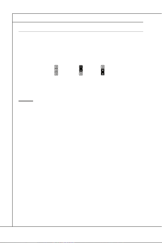
MS-7618 Mainboard
JUMPERS
CMOS leeren-Jumper: JBAT1
JBAT1
1 11
Wichtig
MS-7618 Mainboard
▍
JUMPERS
CMOS leeren-Jumper: JBAT1
Auf der Hauptplatine befi ndet sich ein CMOS RAM, das von einer zusätzlichen Batterie
mit Strom versorgt wird, um die Systemkonfi gurationsdaten zu behalten. Mit den Daten
im CMOS RAM kann das System automatisch das Betriebssystem hochfahren, wann
immer das System eingeschaltet wird. Wenn Sie die Systemkonfi guration löschen.
JBAT1 Halten Daten Löschen Daten
Wichtig
Wenn das System ausgeschaltet ist, können Sie die Steckbrücke auf den Pol 2 und
3 stecken, um die Daten im CMOS zu löschen. Stecken Sie anschließnd die Steckbrücke auf den Pol 1 und 2 zurück. Versuchen Sie niemals die Daten im CMOS zu
löschen, wenn das System eingeschaltet ist. Die Hauptplatine kann dadurch beschädigt
werden.
De-14
Page 49

Deutsch
STECKPLÄTZE
PCI (Peripheral Component Interconnect) Steckplatz
Wichtig
PCI-Unterbrechungsanforderungs-Routing
Folge1 Folge2 Folge3 Folge4
STECKPLÄTZE
PCI (Peripheral Component Interconnect) Steckplatz
Der PCI-Steckplatz kann LAN-Karten, SCSI-Karten, USB-Karten und sonstige Zusatzkarten aufnehmen, die mit den PCI-Spezifi kationen konform sind.
32-Bit PCI Steckplatz
Wichtig
Achten Sie darauf, dass Sie zuerst das Netzkabel aus der Steckdose herausziehen,
bevor Sie eine Erweiterungskarte installieren oder entfernen. Denken Sie bitte auch
daran die Dokumentation der Erweiterungskarte zu lesen, um notwendige Hardwareoder Softwareeinstellungen für die Erweiterungskarte wie z.B. Jumper-, Schalter- oder
BIOS-Einstellungen vorzunehmen.
PCI-Unterbrechungsanforderungs-Routing
Eine IRQ (Interrupt Request; Unterbrechungsanforderung)-Leitung ist eine Hardwareleitung, über die ein Gerät Unterbrechungssignale zu dem Mikroprozessor schicken kann.
Die PCI IRQ-Pole werden in der Regel mit dem PCI-Bus-Polen wie folgt verbunden:
PCI
Steckplatz1 INT B# INT C# INT D# INT A#
Folge1 Folge2 Folge3 Folge4
De-15
Page 50

MS-7618 Mainboard
BIOS SETUP
Wichtig
MS-7618 Mainboard
▍
BIOS SETUP
Dieses Kapitel enthält Informationen über das BIOS Setup und ermöglicht es Ihnen,
Ihr System optimal auf Ihre Anforderungen einzustellen. Notwendigkeit zum Aufruf des
BIOS besteht, wenn:
Während des Bootvorgangs des Systems eine Fehlermeldung erscheint und
■
Sie zum Aufruf des BIOS SETUP aufgefordert werden.
Sie die Werkseinstellungen zugunsten individueller Einstellungen ändern wol-
■
len.
Wichtig
Die Menüpunkte jeder BIOS Kategorie, die in diesem Kapitel beschrieben wird,
•
werden permanent auf den neuesten Stand gebracht, um die Systemleistung zu verbessern. Aus diesem Grunde kann die Beschreibung geringfügig von der aktuellsten
Version des BIOS abweichen und sollte dementsprechend lediglich als Anhaltspunkt
dienen.
Während des Hochfahrens, wird die BIOS Version in der ersten Zeile nach dem Ho-
•
chzählen des Speichers angezeigt, üblicherweise im Format dieses Beispiels:
Die erste Stellen den BIOS-Hersteller bezeichnet, dabei gilt A = AMI, W =
AWARD, und P = PHOENIX.
2te - 5te Stelle bezeichnen die Modelnummer.
6te Stelle bezeichen den Chipsatzhersteller, A = AMD, I = Intel, V = VIA, N
=Nvidia, U = ULi.
7te - 8te Stelle beziehen sich auf den Kunden, MS=alle Standardkunden.
V1.0 bezieht sich auf die BIOS Version.
020110 bezeichnet das Datum der Veröff entlichung des BIOS.
De-16
A7618IMS V1.0 020110 wobei:
Page 51

Deutsch
Aufruf des BIOS Setups
Press DEL to enter SETUP
(ENTF drücken, um das Einstellungsprogramm zu öff nen)
Hilfe fi nden
Hauptmenü
Bildschirmrand
Allgemeine Hilfe <F1>
Aufruf des BIOS Setups
Nach dem Einschalten beginnt der Computer den POST (Power On Self Test -Selbstüberprüfung nach Anschalten). Sobald die Meldung unten erscheint, drücken Sie die
Taste <Entf>(<Del>) um das Setup aufzurufen.
(ENTF drücken, um das Einstellungsprogramm zu öff nen)
Wenn die Nachricht verschwindet, bevor Sie reagieren und Sie möchten immer noch
ins Setup, starten Sie das System neu, indem Sie es erst AUS- und danach wieder
ANSCHALTEN, oder die “RESET”-Taste am Gehäuse betätigen. Sie können das System außerdem neu starten, indem Sie gleichzeitig die Tasten <Strg>,<Alt> und <Entf>
drücken (bei manchen Tastaturen <Ctrl>,<Alt> und <Del>).
Hilfe fi nden
Nach dem Start des Setup Menüs erscheint zuerst das Hauptmenü.
Hauptmenü
Das Hauptmenü listet Funktionen auf, die Sie ändern können. Sie können die Steuer-
tasten ( ↑↓ ) verwenden, um einen Menüpunkt auszuwählen. Die Online-Beschreibung
des hervorgehobenen Menüpunktes erscheint am unteren Bildschirmrand.
Bildschirmrand
Wenn Sie an der linken Seite bestimmter Felder ein Dreieckssymbol fi nden (wie re-
chts dargestellt), bedeuted dies, dass Sie über das entsprechende Feld ein Untermenü
mit zusätzlichen Optionen aufrufen können. Durch die Steuertasten ( ↑↓ ) können Sie
ein Feld hervorheben und durch Drücken der Eingabetaste <Enter> in das Untermenü
gelangen. Dort können Sie mit den Steuertasten Werte eingeben und navigieren. Durch
Drücken von <Esc > kommen Sie zurück ins Hauptmenü.
Allgemeine Hilfe <F1>
Das BIOS Setup verfügt über eine Allgemeine Hilfe (General Help). Sie können diese
aus jedem Menü einfach durch Drücken der Taste <F1> aufrufen. Sie listet die Tasten
und Einstellungen zu dem hervorgehobenen Menüpunkt auf. Um die Hilfe zu verlassen,
drücken Sie <Esc>.
Press DEL to enter SETUP
De-17
Page 52
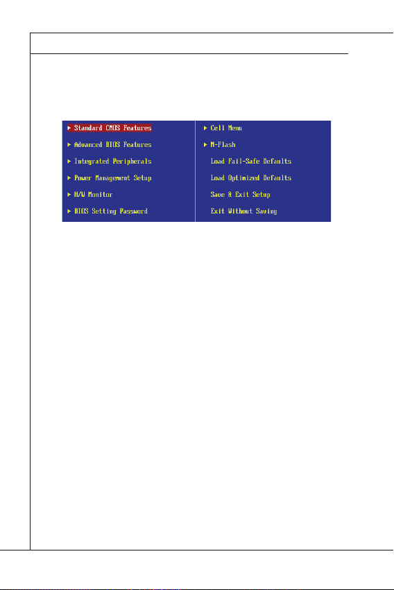
MS-7618 Mainboard
Das Hauptmenü
Standard CMOS Features
Advanced BIOS Features
Integrated Peripherals
Power Management Setup
H/W Monitor
BIOS Setting Password
Cell Menu
M-Flash
MS-7618 Mainboard
▍
Das Hauptmenü
Nachdem Sie das BIOS CMOS Setup Utility, aufgerufen haben, erscheint das Haupt-
menü. Es weist zehn Setup- Funktionen und zwei Arten das Menü zu verlassen auf.
Verwenden Sie die Pfeiltasten, um im Menü zu navigieren und drücken Sie die Eingabetaste (<Enter>), um ein Untermenü aufzurufen.
Standard CMOS Features
▶
In diesem Menü können Sie die Basiskonfi guration Ihres Systems anpassen, so z.B.
Uhrzeit, Datum usw.
Advanced BIOS Features
▶
Verwenden Sie diesen Menüpunkt, um weitergehende Einstellungen an Ihrem System
vorzunehmen.
Integrated Peripherals
▶
Verwenden Sie dieses Menü, um die Einstellungen für in das Board integrierte
Peripheriegeräte vorzunehmen.
Power Management Setup
▶
Verwenden Sie dieses Menü, um die Einstellungen für die Stromsparfunktionen
vorzunehmen.
H/W Monitor
▶
Dieser Eintrag zeigt den generellen Systemstatus.
BIOS Setting Password
▶
Verwenden Sie dieses Menü, um das Kennwort für das BIOS einzugeben.
Cell Menu
▶
Hier können Sie Ihre Einstellungen zur Kontrolle von Frequenz und Spannung und zur
Übertaktung vornehmen.
M-Flash
▶
In diesem Menü können Sie das BIOS vom Speicher-Antrieb abtasten/ aufblinken (nur
FAT/ FAT32 Format).
De-18
Page 53

Deutsch
Load Fail-Safe Defaults
Load Optimized Defaults
Save & Exit Setup
Exit Without Saving
▶
Load Fail-Safe Defaults
In diesem Menü können Sie eine stabile, werkseitig gespeicherte Einstellung des BIOS
Speichers laden. Nach Anwählen des Punktes sichern Sie die Änderungen und starten
das System neu.
Load Optimized Defaults
▶
In diesem Menü können Sie die BIOS-Voreinstel l ungen laden, die der Mainboardher-
steller zur Erzielung der besten Systemleistung vorgibt.
Save & Exit Setup
▶
Abspeichern der BIOS-Änderungen im CMOS und verlassen des BIOS.
Exit Without Saving
▶
Verlassen des BIOS´ ohne Speicherung, vorgenommene Änderungen verfallen.
De-19
Page 54

MS-7618 Mainboard
Wichtig
MS-7618 Mainboard
▍
Wenn Sie das BIOS Dienstprogramm öff nen, folgen Sie den untenstehenden Anweisungen.
Laden der optimalen Voreinstellung : Verwenden Sie die Steuerschlüssel (↑↓), um
1.
dem Laden der optimalen Voreinstellung zu wählen und drücken Sie auf <Eingabe>. Dann erscheint die folgende Meldung:
Drücken Sie auf [OK] und <Enter>, um die im Werk eingestellten Standardwerte für
eine optimale Systemleistung zu laden.
Die Datum/Zeit Einstellung : Wählen Sie die “Standard-CMOS Features” vor und
2.
drücken Sie <Eingabe> um das Standard-CMOS Features-Menü zu wählen. Passen Sie nun die Felder “Datum” und “Zeit” an.
Abspeichern u. Beenden der Einstellung: Verwenden Sie die Steuerschlüssel (↑
3.
↓), um dem Abspeichern u. Beenden der Einstellungen zu wählen und drücken Sie
auf <Eingabe>. Es erscheint folgende Meldung:
Drücken Sie auf [OK] und <Enter>, um die (neuen) Einstellungen zu speichern und
das BIOS Setup zu verlassen.
Wichtig
Die Konfi guration oben dienen nur generellen Zwecken. Wenn Sie detaillierte BIOSEinstellungen benötigen, dann sehen Sie bitte das Handbuch in Englischer Sprache
auf der MSI Website ein.
De-20
Page 55
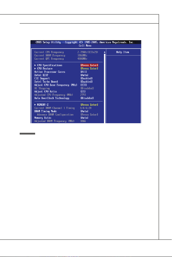
Deutsch
Wichtig
Current CPU / DRAM Frequency
CPU Specifi cations
CPU Technology Support
CPU Feature
Hyper-Threading Function
4.
Cell Menu Introduction : Das Menü ist für den weiteren Benutzer, der die Hauptplatine übertakten mögen.
Wichtig
Nur wenn Sie mit dem Chipsatz vertraut sind, können Sie die Einstellung ändern.
Current CPU / DRAM Frequency
▶
Zeigt die derzeitige Frequenz der CPU, Speicher und die Geschwindigkeit des CPU-
NBs. Nur Anzeige.
CPU Specifi cations
▶
Drücken Sie die Eingabetaste <Enter>, um das Untermenü aufzurufen. Das Untermenü
zeigt die Information des installierten CPUs.
CPU Technology Support
▶
Drücken Sie die Eingabetaste <Enter>, um das Untermenü aufzurufen. Das Unter-
menü zeigt den Technologien, die angebrachte CPU sich unterstützt.
CPU Feature
▶
Drücken Sie die Eingabetaste <Enter>, um das Untermenü aufzurufen.
Hyper-Threading Function
▶
Der Prozessor verwendet die Technologie des Hyper-Threadings, um Verhandlun-
grate zu erhöhen und die Antwortzeiten des Benutzers zu verringern. Die Technologie behandelt den dual-core Prozessor als zwei logische Prozessoren, die
Anweisungen gleichzeitig durchführen können. Somit, das Systemleistung wird hochverbessert. Wenn Sie die Funktion ausgeschaltet, verwendet der Prozessor nur
einen Kern, um die Anweisungen durchzuführen. Bitte deaktiveren Sie die Funktion
wenn Ihr Betriebssystem nicht HT Funktion stützt, oder Unzuverlässigkeit und Instabilität können auftreten.
De-21
Page 56

MS-7618 Mainboard
Wichtig
Execute Bit Support
Set Limit CPUID MaxVal to 3
Memory-Z
DIMM1~2 Memory SPD Information
Advance DRAM Confi guration
DRAM Timing Mode
CAS Latency (CL)
MS-7618 Mainboard
▍
Wichtig
Für das Ermöglichen der Funktionalität der Hyper-Threading Technologie wird die ALLE
folgende Systemkonfi guration empfohlen:
•
CPU: Ein Intel
•
Chipsatz: Ein Intel
•
BIOS: Die HT-Technologie wird unterstützt und ist aktiviert;
•
OS: Das Betriebssystem unterstützt die HT-Technologie.
®
Processor mit der HT-Technologie;
®
Chipsatz, das die HT-Technologie unterstützt;
Weitere Informationen zu Hyper-threading Technologie fi nden Sie unter:
http://www.intel.com/products/ht/hyperthreading_more.htm
Execute Bit Support
▶
Die Funktionalität des Intel’s Execute Disable Bits kann bestimmte Kategorien der
böswilligen “Buff er Overfl ow” Angriff e verhindern, wenn es mit einem stützenden
Betriebssystem kombiniert wird. Das Execute Disable erlaubt dem Prozessor, einzustufen Bereiche im Speicher durch, dem Anwendung Code durchführen kann und
dem er nicht kann. Wenn eine böswillige Wurm versucht die Code im Puff er einzusetzen, sperrt der Prozessor dem Codeablauf, der Schadenverhinderung oder Wurmausbreitung.
▶
Set Limit CPUID MaxVal to 3
Max CPUID Value Limit kann die aufgeführte Geschwindigkeit des Prozessors zu
den älteren Betriebssystemen begrenzen.
▶
Memory-Z
Drücken Sie die Eingabetaste <Enter>, um das Untermenü aufzurufen.
▶
DIMM1~2 Memory SPD Information
Drücken Sie die Eingabetaste <Enter>, um das Untermenü aufzurufen. Das Untermenü zeigt die Informationen des installierten Speichers an.
Advance DRAM Confi guration
▶
Lautet die Einstellung unter DRAM Timing [Manual], wird das das Untermenü aktiviert.
Drücken Sie die Eingabetaste <Enter>, um das Untermenü aufzurufen.
DRAM Timing Mode
▶
Wählen Sie aus, ob DRAM-Timing durch das SPD (Serial Presence Detect) EE-
PROM auf dem DRAM-Modul gesteuert wird. Die Einstellung [Auto] ermöglicht die
automatische Erkennung des DRAM timings und der folgenden “Advance DRAM
Confi guration” Untermenü durch das BIOS auf Basis der Einstellungen im SPD. Das
Vorwählen [Manual] eingestellt, können Sie den DRAM Timing und die folgenden
“Advance DRAM Confi guration” Untermenü anpassen.
CAS Latency (CL)
▶
Lautet die Einstellung unter DRAM Timing [Manual], können Sie hier die DRAM Tim-
ing angeben. Hier wird die Verzögerung im Timing (in Taktzyklen) eingestellt, bevor
das SDRAM einen Lesebefehl nach dessen Erhält auszuführen beginnt.
De-22
Page 57

Deutsch
tRCD
tRP
tRAS
Auto Disable DRAM/PCI Frequency
CPU VTT (V)/ DRAM Voltage (V)/ CPU NB (V)/ SB 1.50 (V)
Spread Spectrum
Wichtig
tRCD
▶
Wenn DRAM erneuert wird, werden Reihen und Spalten separat adressiert. Gestattet
es, die Anzahl der Zyklen der Verzogerung im Timing einzustellen, die zwischen den
CAS und RAS Abtastsignalen liegen, die verwendet werden, wenn der DRAM beschr ieben, ausgelesen oder aufgef rischt wird. Eine hohe Geschwindigkeit fuhrt zu
hoherer Leistung, während langsamere Geschwindigkeiten einen stabileren Betrieb
bieten.
tRP
▶
Legt die Anzahl der Taktzyklen fest, die das Reihenadress Strobe - RAS) für eine
Vorladung bekommt. Wird dem RAS bis zur Auff rischung des DRAM nicht genug
Zeit zum Aufbau seiner Ladung gegeben, kann der Refresh unvollstandig ausfallen
und das DRAM Daten verlieren. Dieser Menüpunkt ist nur relevant, wenn synchroner DRAM verwendet wird.
▶
tRAS
Diese Einstellung stellt das Nehmen der Zeit RAS fest, um von zu lesen und zu einer
Speicherzelle zu schreiben.
▶
Auto Disable DRAM/PCI Frequency
Lautet die Einstellung auf [Enabled] (eingeschaltet), deaktiviert das System die Taktung
leerer PCI Sockel, um die Elektromagnetische Störstrahlung (EMI) zu minimieren.
▶
CPU VTT (V)/ DRAM Voltage (V)/ CPU NB (V)/ SB 1.50 (V)
Diese Option bietet Ihnen an, die Spannung des CPU, des Speichers, CPU NB und SB
anzupassen.
Spread Spectrum
▶
Pulsiert der Taktgenerator des Motherboards, erzeugen die Extremwerte (Spitzen) der
Pulse EMI (Elektromagnetische Interferenzen). Die Spread Spectrum Funktion reduziert die erzeugten EMI, indem die Pulse so moduliert werden, das die Pulsspitzen zu
fl acheren Kurven reduziert werden.
Wichtig
Sollten Sie keine Probleme mit Interferenzen haben, belassen Sie es bei der Einstel-
•
lung [Disabled] (ausgeschaltet ) , um bestmögliche Systemstabilität und -leistung zu
gewährleisten. Stellt für sie EMI ein Problem dar, wählen Sie die gewünschte Bandbreite zur Reduktion der EMI.
Je größer Spread Spectrum Wert ist, desto größer nimmt der EMI ab, und das Sys-
•
tem wird weniger stabil. Bitte befragen Sie Ihren lokalen EMI Regelung zum meist
passend Spread Spectrum Wert.
Denken Sie daran Spread Spectrum zu deaktivieren, wenn Sie übertakten, da sogar
•
eine leichte Schwankung eine vorübergehende Taktsteigerung erzeugen kann, die
gerade ausreichen mag, um Ihren übertakteten Prozessor zum einfrieren zu bringen.
De-23
Page 58

MS-7618 Mainboard
SOFTWARE-INFORMATION
Wichtig
MS-7618 Mainboard
▍
SOFTWARE-INFORMATION
Die im Mainboard-Paket enthaltene DVD enthält alle notwendigen Treiber. Um die
Installation automatisch laufen zu lassen, klicken Sie einfach den Treiber oder Utiltiy
und folgen Sie dem Pop-Up Schirm, um die Installation durchzuführen. Der Treibergebrauchs-DVD enthält:
Treibermenü - das Treibermenü zeigt die vorhandenen Treiber. Aktivieren Sie den
gewünschten Treiber.
Gebrauchsmenü - das Gebrauchsmenü zeigt die Software-Anwendungen der die
Mainboard Unterstützungen.
WebSite Menü - das Website Menü zeigt die betreff ende Website.
-
Wichtig
Besuchen Sie bitte die MSI Website, um die neuesten Treiber und BIOS für bessere
System Leistung zu erhalten.
De-24
Page 59

Wind Board
D510/ D410
Séries
Français
Wind Board
D510/ D410
Séries
Français
Europe version
Page 60

Carte mère MS-7618
SPÉCIFICATIONS
Processeurs Supportés
Fréquence d’horloge externe d’horloge de Base
Jeu de puces
Mémoire supportée
LAN
Audio
SATA
Connecteurs
Carte mère MS-7618
▍
SPÉCIFICATIONS
Processeurs Supportés
■
Supporte Intel® Atom CPU D510/ D410
Fréquence d’horloge externe d’horloge de Base
■
100 MHZ
Jeu de puces
■
Mémoire supportée
■
■
LAN
■
■
■
Audio
■
■
SATA
■
Connecteurs
■
■
®
Puces Intel
DDR2 800 SDRAM (4GB Max)
2 DDR2 DIMMs (240pin / 1.8V), simple canal
*(Pour plus d’information sur les composants compatibles, veuillez visiter
http://www.msi.com/index.php?func=testreport)
Supporte Realtek® RTL8103EL 10/100 Mb/s
Supporte Realtek
Supporte ACPI Gestion d’énergie
Puce intégrée par Realtek® ALC888S
Supporte 6-canaux audio out
2 ports SATA 3 Gb/s par Intel® NM10
Panneau arrière
‑
‑
‑
‑
‑
‑
‑
Connecteurs intégrés
‑
‑
‑
‑
‑
‑
NM10
®
RTL8111DL 10/100/1000 Mb/s (en option)
1 port souris PS/2
1 port clavier PS/2
1 port sérial
1 port VGA
4 ports USB 2.0
1 prise RJ-45 LAN
3 prises audio fl exibles
2 connecteurs USB 2.0
1 connecteur de port parallèle
1 connecteur audio avant
1 connecteur S/PDIF-Out
1 connecteur Châssis Intrusion
1 connecteur TPM
Fr-2
Page 61

Français
Emplacements
Dimension
Montage
Emplacements
1 emplacement PCI
■
Supporte l’Interface bus PCI 3.3V/ 5V
■
Dimension
Mini-ITX (17.0cm X 17.0cm)
■
Montage
4 trous de montage
■
(Si vous désirez acheter des accessoires et vous avez besoin de numéro des pièces,
vous pouvez chercher sur la page website et trouver les détails sur notre adresse cidessous
http://www.msi.com/index.php)
Fr-3
Page 62

Carte mère MS-7618
GUIDE RAPIDE DES COMPOSANTS
Panneau
arrière
DDR2
JCI1
JPWR1
JTPM1
SATA
SYSFAN1
JFP1
JUSB1~2
PCI
JPWR2
JBAT1
SYS FAN2
JLPT1
JAUD1
JSP1
Carte mère MS-7618
▍
GUIDE RAPIDE DES COMPOSANTS
JPWR2, Fr-7
JCI1, Fr-9
SYSFAN2,
Fr-10
JAUD1, Fr-11
Panneau
arrière
Fr-8
JSP1, Fr-13
PCI, Fr-15
JLPT1, Fr-12
SYSFAN1, Fr-10
JBAT1, Fr-14
JTPM1, Fr-12
DDR2, Fr-5
JUSB1~2, Fr-11
JPWR1, Fr-7
SATA, Fr-9
JFP1, Fr-10
Fr-4
Page 63

Français
MÉMOIRE
DDR2
240-pin, 1.8V
64x2=128 pin
56x2=112 pin
Règles de population de mémoire
1
2
Important
MÉMOIRE
Ces slots DIMM sont destinés à installer les modules de mémoire. Pour plus
d’informations sur les composants compatibles, veuillez visiter
dex.php?func=testreport
DDR2
240-pin, 1.8V
Règles de population de mémoire
Veuillez vous référer aux illustrations ci-dessous pour les règles de population de mémoire.
1
DIMM1
2
DIMM1
64x2=128 pin
http://www.msi.com/in-
56x2=112 pin
DIMM2
DIMM2
Important
L
es modules de mémoire DDR2 ne sont pas interchangeables par DDR et vice versa.
•
Vous devez toujours installer les modules de mémoire DDR2 dans les slots DDR2
M.
DIM
Pour lancer avec succès votre ordinateur, insérez tout d’abord les modules de mé-
•
moire dans le DIMM1
•
A cause du développement de la ressource du chipset, la densité du système sera
détecté seulement jusqu’à 3+GB (non 4GB plein) quand chaque DIMM est installé
avec un module de mémoire de 2GB.
.
Installé
Vide
Fr-5
Page 64

Carte mère MS-7618
Installation des modules de mémoire
Important
Carte mère MS-7618
▍
Installation des modules de mémoire
Le module de mémoire possède une seule encoche en son centre et ne s’adaptera
1.
que s’il est orienté de la mqnière convenable.
Insérez le module de mémoire à la verticale dans le slot du DIMM. Poussez-le en-
2.
suite jusqu’à l’extrémité dorée du module de mémoire, soit profondément insérée
dans le slot du DIMM. Les clips en plastique situés de chaque côté du module va
se fermer automatiquement.
Vérifi ez manuellement si la barrette mémoire a été verrouillée en place par les clips
3.
du slot DIMM sur les côtés.
Encoche
Volt
Important
Vous pourriez à peine voir l’extrémité dorée si le module de mémoire est correctement
inséré dans le slot du DIMM.
Fr-6
Page 65

Français
CONNECTEURS D’ALIMENTATION
Connecteur d’alimentation ATX 24-pin : JPWR1
V
1
Connecteur d’alimentation ATX 4-pin : JPWR2
V
1
Important
CONNECTEURS D’ALIMENTATION
Connecteur d’alimentation ATX 24-pin : JPWR1
Ce connecteur vous permet de connecter l’alimentation ATX 24-pin. Pour cela, assurez-vous que la prise d’alimentation est bien positionnée dans le bon sens et que les
goupilles soient alignées. Enfoncez alors la prise dans le connecteur.
Vous pourvez aussi utiliser un alimentation 20-pin selon vos besoins. Veuillez brancher
votre alimentation d’énergie avec le pin 1 et le pin 13 si vous voulez utiliser l’alimentation
ATX 20-pin.
2.+3.3V
11.+12V
10.+12V
9.5VSB
8.PWR OK
7.Ground
6.+5V
5.Ground
4.+5V
3.Ground
2.+3.3V
1.+3.3V
17.Ground
16.PS-ON#
15.Ground
14.-12V
13.+3.3
Connecteur d’alimentation ATX 4-pin : JPWR2
Ce connecteur d’alimentation sert à alimenter le CPU.
.Ground
2.Ground
22.+5V
21.+5V
20.Res
19.Ground
18.Ground
3.+12V
4.+12
24.Ground
23.+5V
Important
Veuillez vous assurer que tous les connecteurs sont connectés aux correctes alimen-
•
tations ATX pour garantir une opération stable de la carte mère.
L’alimentation de 350 watts (et plus) est fortement recommandée pour la stabilité du
•
système.
Fr-7
Page 66
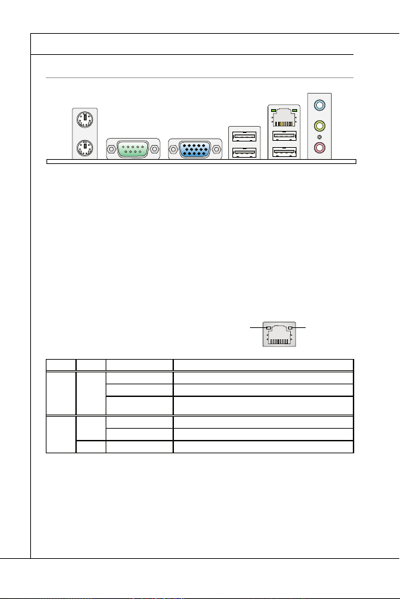
Carte mère MS-7618
PANNEAU ARRIÈRE
Souris/Clavier
Port Sérial
Port VGA
Port USB
LAN
LED
Couleur
LED Statut
Condition
Ports Audio
Souris
Ligne-In
Port USB
Clavier
Port VGA
LAN
Port USB
Port sérial
Ligne-Out
Mic
Carte mère MS-7618
▍
PANNEAU ARRIÈRE
Ligne-In
Souris
Clavier
▶
Souris/Clavier
Le standard connecteur de souris/clavier DIN de PS/2
®
de PS/2
▶
Port Sérial
Ce connecteur de sérial est un port de communication de haute vitesse 16550A qui
envoie/ reçoit 16 bytes FIFOs. Vous pouvez y attacher une souris de série ou autres
composants de série directement.
▶
Port VGA
Le connecteur féminin de DB15-pin est fournit pour un moniteur.
▶
Port USB
Le port USB (Universal Serial Bus) sert à brancher des périphériques USB tels que le
clavier, la souris, ou d’autres périphériques compatibles USB.
▶
LAN
La prise standard RJ-45 LAN sert à la connexion
au réseau local (Local Area Network (LAN)). Vous
pouvez y relier un câble de réseau.
LED
Gauche Jaune Eteinte La connexion au réseau LAN n’est pas établie.
Droite Vert Eteinte Un débit de 10 Mbits/sec est sélectionné.
Ports Audio
▶
Ces connecteurs audio servent pour les périphériques audio. Vous pouvez diff érencier
la couleur des prises audio pour obtenir divers eff ets sonores.
Ligne-In (Bleu) - Ligne In, est utilisée pour un appareil de CD externe, cassette
■
ou d’autre périphériques.
Ligne-Out (Vert) - Ligne Out, est destiné aux haut-parleurs ou aux casques
■
d’écoute.
Mic (Rose) - Mic, est un connecteur pour les microphones.
■
Port sérial
.
Couleur
LED Statut
Allumée(Stable) La connexion au réseau LAN est établie.
Allumée(plus brillant
et clignotante)
Allumée Un débit de 100 Mbits/sec est sélectionné.
Orange Allumée Un débit de 1000 Mbits/sec est sélectionné.
Port VGA
Condition
L’ordinateur communique avec un autre ordinateur sur le réseau
local LAN.
Port USB
Jaune Vert/ Orange
LAN
Ligne-Out
Port USB
®
est pour une souris ou un clavier
Mic
Fr-8
Page 67

Français
CONNECTEURS
Connecteur Sérial ATA : SATA1~2
F
l
o
p
p
y
D
M
S
I
F
l
o
p
p
y
D
M
S
I
K
d
k
l
k
d
k
f
k
k
k
f
d
k
k
l
d
d
f
k
k
k
s
d
d
f
d
d
f
a
s
d
k
a
d
f
-
d
d
f
d
d
a
d
d
f
d
f
d
d
d
d
d
f
a
d
f
a
d
k
j
a
s
j
d
k
d
f
d
f
a
s
d
d
d
f
f
a
s
d
f
d
d
d
d
d
d
d
f
d
a
s
f
d
a
s
a
s
d
f
a
s
d
a
s
d
a
s
d
d
d
d
d
d
d
f
a
s
a
s
d
f
s
d
f
f
s
d
f
a
d
f
f
f
a
s
d
f
f
f
d
f
Important
Connecteur Châssis Intrusion : JCI1
U
d
CONNECTEURS
Connecteur Sérial ATA : SATA1~2
Ce connecteur est un port d’interface de série ATA haut débit. Chaque connecteur peut
être relié à un appareil de série ATA.
l
k
k
d
f
k
k
f
d
k
f
d
d
f
k
d
d
f
d
f
k
d
d
d
s
l
a
d
k
d
f
k
-
d
s
d
k
a
d
f
k
K
f
d
f
d
d
a
d
d
f
d
d
k
d
d
d
f
d
k
d
d
s
d
d
f
a
d
j
f
s
d
d
d
f
a
d
s
j
a
a
d
s
s
k
d
a
a
f
a
d
f
f
s
d
d
a
s
d
a
f
f
d
d
d
d
s
d
f
a
d
d
d
f
s
d
s
d
f
d
a
f
f
f
d
f
d
s
s
d
f
a
s
d
a
s
f
f
a
f
d
a
D
y
p
l
p
k
k
o
d
f
l
k
k
f
k
F
I
d
f
d
d
f
k
d
S
f
d
d
f
k
d
d
d
l
a
d
s
f
k
k
d
-
d
s
d
k
M
f
K
a
d
k
f
d
d
f
d
d
d
d
a
f
k
d
d
d
d
f
d
d
k
d
s
d
d
j
f
a
d
f
d
d
s
a
d
d
f
j
s
a
d
a
k
s
s
a
d
a
f
a
d
f
f
s
d
a
d
D
s
d
f
a
d
f
d
d
y
d
s
f
d
a
f
d
d
d
p
s
d
s
d
f
f
f
d
a
f
d
p
f
d
s
s
d
f
a
s
o
d
a
s
f
l
f
a
f
d
F
I
a
S
D
M
y
p
p
o
l
F
I
S
M
Important
Veuillez ne pas plier le câble de série ATA à 90°. Autrement des pertes de données
pourraient se produire pendant la transmission
Connecteur Châssis Intrusion : JCI1
Ce connecteur est connecté à un câble châssis intrusion switch. Si le châssis est
ouvert, le switch en informera le système, qui enregistera ce statut et affi chera un écran
d’alerte. Pour eff acer ce message d’alerte, vous devez entrer dans le BIOS et désactiver l’alerte.
.
2
.
G
1
r
.
C
o
u
I
N
n
T
R
Fr-9
Page 68

Carte mère MS-7618
Connecteurs d’alimentation du ventilateur : SYSFAN1~2
r
Connecteurs panneau avant : JFP1
h
D
Carte mère MS-7618
▍
Connecteurs d’alimentation du ventilateur : SYSFAN1~2
Les connecteurs de courant du ventilateur supportent le ventilateur de refroidissement
du système avec +12V. Lors du branchement des fi ls aux connecteurs, faites toujours
en sorte que le fi l rouge soit le fi l positif devant être relié au connecteur +12V; et que
le fi l noir soit le fi l de mise à la terre devant être relié au connecteur de mise à la terre
GND. Si la carte mère est équipée d’un jeu de puces intégré pour moniteur de matériel
de système, vous devrez utiliser un ventilateur spécial pourvu d’un capteur de vitesse
afi n de contrôler le ventilateur de l’unité centrale.
1
.
2
G
.
r
+
3
o
1
.
u
S
2
n
e
V
d
n
s
o
Connecteurs panneau avant : JFP1
Ce connecteur est fourni pour la connecxion électrique aux interrupteuts et LEDs du
panneau avant. Le JFP1 est conforme au guide de conception de la connectivité Entrée/sortie du panneau avant Intel
Power LED
Power Switch
2.+
®
.
10.NoPin
8.-
6.+
4.-
9.Reserv ed
7.+
5.-
3.-
1.+
Reset Switc
HDD LE
Fr-10
Page 69
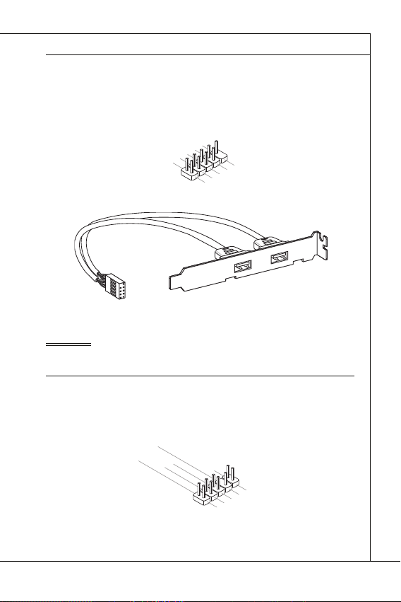
Connecteurs USB avant : JUSB1 / JUSB2
C
1
n
Important
Connecteur audio panneau avant : JAUD1
1
L
Connecteurs USB avant : JUSB1 / JUSB2
Ce connecteur est conforme au guide de conception de la connectivité Entrée/sortie du
panneau avant Intel
débit tels les disques durs externes, les appareils photo numériques, les lecteurs MP3,
les imprimantes, les modems et les appareils similaires.
®
, il est idéal pour relier les périphériques d’interface USB à haut
0
.
8
U
.
S
G
6
B
r
.
o
U
4
2
.
V
O
u
S
.
U
C
C
n
B
d
S
D
B
+
D
C
-
9
.
N
7
o
.
G
5
P
.
r
U
i
o
3
u
.
S
U
1
n
B
S
.
d
D
V
B
C
+
D
-
Support USB 2.0 (en option)
Important
Notez que les pins de VCC (Connexion de virtuelle) et GND (terre) doivent être branchées correctement afi n d’éviter tout dommage possible.
Connecteur audio panneau avant : JAUD1
Ce connecteur vous permet de connecter un audio sur le panneau avant.Il est conforme
au guide de conception de la connectivité Entrée/sortie du panneau avant Intel
0
.
8
H
.
e
N
6
a
o
.
d
M
4
P
P
I
.
i
C
P
n
2
.
G
r
o
u
h
R
o
D
E
n
n
e
S
d
e
t
e
E
D
c
N
e
t
i
C
t
o
e
n
E
c
#
t
i
o
n
9
.
H
7
e
.
S
5
a
E
.
d
H
3
1
.
M
N
P
.
e
M
S
h
a
E
o
I
d
C
I
C
L
n
_
P
e
S
R
h
E
o
N
n
e
D
R
Français
®
.
Fr-11
Page 70
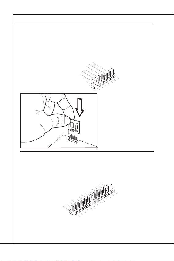
Carte mère MS-7618
Connecteur du Module TPM : JTPM1
1
2
0
3
Connecteur de port parallèle : JLPT1
Carte mère MS-7618
▍
Connecteur du Module TPM : JTPM1
Ce connecteur est rélié à TPM (Trusted Platform Module) Module (optionnel). Veuillez
vous référer au manuel de TPM plat-forme (optionnel) de sécurité pour plus de détails
et d’utilisations.
4
1
.
G
2
1
.
r
G
o
0
u
.
r
8
N
o
n
.
u
o
d
5
6
n
V
P
.
S
4
.
3
.
3
.
3
V
S
t
a
Connecteur de port parallèle : JLPT1
Ce connecteur sert à connecter un support de port parallèle en option. Le port parallèle est un port d’imprimante standard qui supporte les modes Enhanced Parallel Port
(EPP) et Extended Capabilities Parallel Port (ECP).
1
6
1
4
1
.
G
2
1
.
G
0
.
r
8
G
o
.
u
r
L
6
o
P
.
u
P
T
4
2
.
A
n
I
_
.
N
E
S
I
R
T
L
R
I
#
F
N
#
D
#
d
i
P
n
e
o
r
i
w
a
e
l
V
I
r
R
P
Q
o
w
e
n
r
d
b
y
p
o
w
e
r
1
2
6
2
.
N
4
2
.
o
G
2
P
2
r
.
G
o
0
1
8
.
G
.
G
r
o
u
r
o
u
n
d
n
d
d
#
i
n
u
.
r
G
o
n
u
d
r
o
n
u
d
r
o
n
u
d
n
d
n
d
1
3
1
1
.
9
P
.
P
7
R
.
P
5
N
R
.
P
3
N
R
.
P
1
D
N
R
.
2
D
R
N
S
1
D
T
0
B
#
1
3
1
.
L
1
P
.
9
L
C
.
P
L
7
5
.
L
3
.
L
P
.
L
C
P
C
C
1
9
1
7
1
.
P
5
.
P
R
.
P
N
R
N
R
D
N
D
D
4
3
F
C
P
.
L
P
R
l
o
2
.
A
R
D
5
r
C
a
a
P
m
d
a
C
d
d
C
a
d
e
s
e
c
k
2
2
3
.
1
.
B
U
C
K
N
D
7
6
e
r
a
d
e
d
r
s
e
d
s
s
r
&
s
e
d
s
r
t
5
.
P
E
S
#
&
e
S
Y
d
s
a
d
s
&
s
L
C
t
a
a
d
t
&
T
a
p
a
d
i
p
t
n
a
a
i
n
t
p
a
2
i
n
p
1
i
n
Fr-12
Page 71

Français
Connecteur S/PDIF-Out : JSP1
Connecteur S/PDIF-Out : JSP1
Ce connecteur sert à connecter l’interface S/PDIF (Sony & Philips Digital Interconnect
Format) pour une transmission audio numérique.
3
.
G
2
.
r
S
o
1
P
u
.
V
n
D
d
C
I
F
C
Support S/PDIF (en option)
Fr-13
Page 72

Carte mère MS-7618
CAVALIERS
Cavalier d’eff acement CMOS : JBAT1
Important
1
1
JBAT1
1
Carte mère MS-7618
▍
CAVALIERS
Cavalier d’eff acement CMOS : JBAT1
Il y a un CMOS RAM intégré, qui possède un bloc d’alimentation alimenté par une batterie externe, destiné à conserver les données de confi guration du système. Avec le
CMOS RAM, le système peut lancer automatiquement le système d’exploitation chaque
fois qu’il est allumé. Si vous souhaitez eff acer la confi guration du système, réglez le
cavalier pour eff acer les données.
JBAT1
Important
Vous pouvez eff acer le CMOS en raccourcissant 2-3 pins quand le système est éteint.
Retournez ensuite en position 1-2 pins. Evitez d’eff acer le CMOS pendant que le système est allumé; cela endommagerait la carte mère.
Fr-14
Conserver les données
Eff acer les données
Page 73

Français
EMPLACEMENTS
Emplacement PCI (Peripheral Component Interconnect)
Important
Chemins de revendication d’interruption de PCI
Ordre1 Ordre2 Ordre3 Ordre4
EMPLACEMENTS
Emplacement PCI (Peripheral Component Interconnect)
L’emplacement PCI supporte la carte LAN, la carte SCSI, la carte USB et d’autres
cartes ajoutées qui sont compatibles avec les spécifi cations de PCI.
Emplacement 32-bit PCI
Important
Lorsque vous ajoutez ou retirez une carte d’extension, assurez-vous que le PC n’est
pas relié au secteur. Lisez la documentation pour faire les confi gurations nécessaires
du matériel ou du logiciel de la carte d’extension, tels que cavaliers, interrupteurs ou la
confi guration du BIOS.
Chemins de revendication d’interruption de PCI
IRQ est l’abréviation de “interrupt request line”. Les IRQ sont des lignes de matériel
sur lesquelles les périphériques peuvent émettre des signaux d’interruption au microprocesseur. Les pins de PCI IRQ sont typiquement connectés aux pins de bus PCI
comme suivant :
PCI Slot1 INT B# INT C# INT D# INT A#
Ordre1 Ordre2 Ordre3 Ordre4
Fr-15
Page 74

Carte mère MS-7618
RÉGLAGE BIOS
Important
Carte mère MS-7618
▍
RÉGLAGE BIOS
Ce chapitre donne des informations concernant le programme de réglage de BIOS et
vous permet de confi gurer le système pour obtenir des performances d’utilisation optimum. Vous aurez peut-être besoin de lancer le programme de réglage quand :
Un message d’erreur apparaît sur l’écran pendant le démarrage du système,
■
qui vous demande de lancer BIOS SETUP (Réglage).
Vous souhaitez changer les réglages par défaut des fonctions personnalisées.
■
Important
Les objets situés sous chaque catégorie BIOS décrits dans ce chapitre sont en cours
•
de mise à jour continue pour améliorer les performances du système. C’est pourquoi
il est possible que la description soit légèrement diff érente du BIOS le plus récent, et
ne doit servir que comme référence.
Au redémarrage, la première ligne qui apparaît après le compte de la mémoire, est la
•
version BIOS. Elle est généralement sous la forme :
Le 1er caractère se rapporte au fabricant du BIOS : A = AMI, W = AWARD,
et P = PHOENIX.
Les caractères de 2ème à 5ème se rapportent au numéro de modèle.
Le 6ème caractère se rapporte au jue de puces : I = Intel, N = NVIDIA, A =
AMD et V = VIA, .
Les caractères de 7ème à 8ème se rapportent au client : MS = all standard
customers (tous les clients standard).
V1.0 se rapporte à la version de BIOS.
020110 se rapporte à la date à laquelle est sortie ce BIOS.
Fr-16
A7618IMS V1.0 020110 où :
Page 75

Français
Réglages d’Entrée
Press DEL to enter SETUP
(Appuyez sur DEL pour entrer dans SETUP)
Obtenir de l’aide
Menu principal
Sous-Menu
Aide générale <F1>
Réglages d’Entrée
Allumez l’ordinateur et le système lancera le processus POST (Test automatique
d’allumage). Lorsque le message ci-dessous apparaît à l’écran, appuyez sur la touche
<DEL> pour entrer dans les réglages.
Press DEL to enter SETUP
(Appuyez sur DEL pour entrer dans SETUP)
Si le message disparaît avant que vous ne répondiez et que vous souhaitez encore
entrer dans Setup (Réglages), redémarrez le système en OFF (éteignant) puis en On
(rallumant) en appuyant sur le bouton RESET (Réinitialiser). Vous pouvez également
redémarrer le système en appuyant simultanément sur les touches <Ctrl>, <Alt>, et
<Delete>.
Obtenir de l’aide
Après être entré dans le menu de Réglage, le premier menu que vous verrez apparaître
sera le menu principal.
Menu principal
Le menu principal établit la liste des fonctions de réglage que vous pouvez modifi er.
Vous pouvez utiliser les touches de fl èche ( ↑↓ ) pour sélectionner l’objet. La description en ligne des fonctions de réglages illuminées est affi chée au bas de l’écran.
Sous-Menu
Si vous un symbole de pointeur droit (comme indiqué sur la vue de droite) apparaît sur
la gauche de certains champs, cela signifi e qu’un sous-menu peut être lancé à partir de
ce champ. Un sous-menu contient des options supplémentaires pour un paramètre de
champ. Vous pouvez utiliser les touches de fl èche ( ↑↓ ) pour illuminer le champ puis
appuyez sur <Enter> pour faire apparaître le sous-menu. Vous pourrez alors utiliser les
touches de commande pour saisir des valeurs et vous déplacer d’un champ à un autre
à l’intérieur d’un sous-menu. Si vous souhaitez revenir au menu principal, appuyez juste
sur <Esc>.
Aide générale <F1>
Le programme de réglages BIOS fournit un écran d’aide générale. Vous pouvez faire
sortir cet écran à partir de n’importe quel menu en appuyant simplement sur <F1>.
L’écran d’aide donne une liste des touches appropriées à utiliser et les sélections possibles pour l’objet illuminé. Appuyez sur <Esc> pour quitter l’écran d’aide.
Fr-17
Page 76

Carte mère MS-7618
Menu principal
Standard CMOS Features (Fonctions CMOS standard)
Advanced BIOS Features (Fonctions BIOS avancées)
Integrated Peripherals (Périphériques intégrés)
Power Management Setup (Réglages de la gestion de l’énergie)
H/W Monitor (Moniteur H/W)
BIOS Setting Password (Mot de passe de réglage BIOS)
Cell Menu (Menu Cell)
M-Flash
Carte mère MS-7618
▍
Menu principal
Une fois entré dans l’unité de réglages BIOS CMOS, le menu principal appaît sur
l’écran. Le Menu Principal vous permet de sélectionner parmi les fonctions et les choix
de sorties. Utilisez les touches de fl èche pour sélectionner parmi les objets et appuyez
sur <Enter> pour accepter ou entrer dans le sous-menu.
▶
Standard CMOS Features (Fonctions CMOS standard)
Utilisez ce menu pour les confi gurations du système de base, tel que l’heure, la date.
▶
Advanced BIOS Features (Fonctions BIOS avancées)
Utilisez ce menu pour régler les objets des fonctions améliorées spéciales.
▶
Integrated Peripherals (Périphériques intégrés)
Utilisez ce menu pour défi nir vos réglages des périphériques intégrés.
▶
Power Management Setup (Réglages de la gestion de l’énergie)
Utilisez ce menu pour défi nir vos réglages de la gestion de l’énergie.
▶
H/W Monitor (Moniteur H/W)
Cette entrée indique l’état de santé de votre PC.
▶
BIOS Setting Password (Mot de passe de réglage BIOS)
Utilisez ce menu pour régler le mot de passe du BIOS.
▶
Cell Menu (Menu Cell)
Utilisez ce menu pour défi nir vos réglages du contrôle de la fréquence/ voltage et de
l’overclocking.
▶
M-Flash
Utilisez ce menu pour lire/ fl ash le BIOS du lecteur de stockage (FAT/ FAT32 format
uniquement).
Fr-18
Page 77

Français
Load Fail-Safe Defaults (Défauts de sécurité de chargement intégrée)
Load Optimized Defaults (Chargement des réglages par défaut optimisés)
Save & Exit Setup (Sauvegarder et quitter les réglages)
Exit Without Saving (Quitter sans sauvegarder)
Load Fail-Safe Defaults (Défauts de sécurité de chargement intégrée)
▶
Utilisez ce menu pour charger les valeur par défauts réglées par le vendeur de BIOS
afi n de garantir la stabilité des performances du système.
▶
Load Optimized Defaults (Chargement des réglages par défaut optimisés)
Utilisez ce menu pour charger les valeurs par défaut réglées par le fabricant de la carte
mère spécifi quement pour obtenir des performances optimales de la carte mère.
▶
Save & Exit Setup (Sauvegarder et quitter les réglages)
Sauvegardez les changements apportés au CMOS puis quittez les réglages.
Exit Without Saving (Quitter sans sauvegarder)
▶
Abandonnez tous les changements et quittez les réglages.
Fr-19
Page 78

Carte mère MS-7618
Important
Carte mère MS-7618
▍
Quand vous entrez dans l’unité de réglages BIOS, suivez les procédures suivantes
pour l’utilisation générale.
Load Optimized Defaults (Chargement des réglages par défaut optimisés) : Utilisez
1.
les touches de contrôle (↑↓ ) afi n de surligner le domaine Load Optimized Defaults et appuyez sur <Enter> , le message suivant appaît :
Choisir [Ok] et appuyer sur Enter chargera les valeurs par défauts pour une performance de système optimal.
Setup Date/ Time (Réglage de l’heure et de la date) : Choisissez Standard CMOS
2.
Features et appuyez sur <Enter> afi n d’entrer dans le menu Standard CMOS Features. Ajustez la date de l’heure.
Save & Exit Setup (Sauvegarder et quitter les réglages) : Utilisez les touches de
3.
contrôle (↑↓ ) afi n de surligner le domaine de Save & Exit Setup et appuyez sur
<Enter> , le message suivant appaît :
Choisir [Ok] et appuyer sur Enter afi n de sauvegarder les confi gurations et l’unité
de réglages de quitter BIOS.
Important
Les confi gurations précédantes ne sont que pour l’utilisation générale. Si vous avez besoin de réglages détaillés du BIOS, veuillez vous référer au manuel de l’édition anglaise
sur le site d’internet de MSI.
Fr-20
Page 79

Français
Important
Current CPU / DRAM Frequency
CPU Specifi cations
CPU Technology Support
CPU Feature
Hyper-Threading Function
4.
Cell Menu Introduction (Introduction du Menu Cell) : Ce menu est pour des utilisations avancées destinées à overclocker la carte mère.
Important
Ne changez pas ces réglages sauf que vous connaissiez bien ces chipsets.
▶
Current CPU / DRAM Frequency
Ces articles montrent les horloges actuelles de la vitesse du CPU, de la mémoire.
Lecture uniquement.
▶
CPU Specifi cations
Appuyez sur <Enter> pour entrer dans le sous-menu. Ce sous-menu montre l’information
du CPU installé.
▶
CPU Technology Support
Appuyez sur <Enter> pour entrer dans le sous-menu. Ce sous-menu montre les
technologies que le CPU installé supporte. Lecture uniquement.
▶
CPU Feature
Appuyez sur <Enter> pour entrer dans le sous-menu.
▶
Hyper-Threading Function
Le processeur utilise la Hyper-Threading Technologie pour augmenter le taux de
transaction et réduire les réponses du dernier-utilisateur. La technologie prend les
deux puces à l’intérieur du processeur pour deux processeurs logiques qui peuvent
exécuter les instructions simultanément. Dans ce cas-là, la performance du système est fortement améliorée. Si vous désactivez la fonction, le processeur n’utilise
qu’une seule puce pour exécuter les instructions. Veuillez désactiver cet article si
votre système d’opération ne supporte pas la fonction HT, ou la faillibilité et instabilité sont possible.
Fr-21
Page 80

Carte mère MS-7618
Important
Execute Bit Support
Set Limit CPUID MaxVal to 3
Memory-Z
DIMM1~2 Memory SPD Information
Advance DRAM Confi guration
DRAM Timing Mode
CAS Latency (CL)
Carte mère MS-7618
▍
Important
Afi n d’activer la fonctionnalité de l’Hyper-Threading Technologie pour le système de
votre ordinateur, il faut tous ces composants de plate-forme suivants :
•
CPU : Un Intel
•
Puce : Une puce Intel
•
BIOS : Un BIOS qui supporte la HT Technologie et qu’il soit activé ;
•
OS : Un système d’opération qui supporte la HT Technologie.
®
Processeur avec la HT Technologie ;
®
qui supporte la HT Technologie ;
Pour plus d’informations sur la Hyper-threading Technologie, allez au site :
http://www.intel.com/products/ht/hyperthreading_more.htm
Execute Bit Support
▶
La fonctionnalité Intel Execute Disable Bit peut prévenir des attaques malicieuses
de “buff er overfl ow” de certaines classes lorsque il est combiné avec un système
d’opération supporant. Cette fonctionnalité permet au processeur de classer les
zônes dans la mémoire par où le code d’application peut exécuter et où il ne peut
pas. Lorsque un ver malicieux tente d’insérer un code dans le buff er, le processeur
désactive l’exécution du code pour prévenir le dommage ou la propagation de vers.
Set Limit CPUID MaxVal to 3
▶
Le Max CPUID Value Limit est destiné à limiter la vitesse listée du processeur aux
systèmes d’opérations plus vieux.
▶
Memory-Z
Appuyez sur <Enter> pour entrer dans le sous-menu.
▶
DIMM1~2 Memory SPD Information
Appuyez sur <Enter> pour entrer dans le sous-menu. Le sous-menu affi che les informations de la mémoire installée.
▶
Advance DRAM Confi guration
Lorsque le DRAM Timing Mode est mis en [Manual], ce sous-menu est disponible. Appuyez <Enter> pour entrer dans le sous-menu.
▶
DRAM Timing Mode
Le choix de décision si le DRAM timing est contrôlé par le SPD (Serial Presence
Detect) EEPROM sur le module DRAM. La mise en [Auto] active le DRAM timings
et le sous-menu "Advance DRAM Confi guration" suivant d'être déterminé par le
BIOS basé sur la confi guration sur le SPD. La mise en [Manual] vous permet de
confi gurer le DRAM timings et le sous-menu "Advance DRAM Confi guration" suivant
manuellement.
▶
CAS Latency (CL)
Il contrôle le latence CAS, qui détermine le retard du timing (en cycle d’horloge)
avant que le SDRAM commence un ordre de lecture après l’avoir reçu.
Fr-22
Page 81

Français
tRCD
tRP
tRAS
Auto Disable DRAM/PCI Frequency
CPU VTT (V)/ DRAM Voltage (V)/ CPU NB (V)/ SB 1.50 (V)
Spread Spectrum
Important
tRCD
▶
Quand le DRAM est rafraîchi, les rangs et les colonnes sont tous adressés séparé-
ment. Cet article vous permet de déterminer le timing de la transition de RAS (row
address strobe) à CAS (column address strobe). Le moins fonctionne l’horloge, le
plus vite est la performance de DRAM.
tRP
▶
Cet article contrôle le numéro de cycles pour que le Row Address Strobe (RAS) soit
permit à précharger. S’il n’y a pas assez de temps pour que le RAS accumule son
charge avant le refraîchissement de to DRAM, le refraîchissement peut être incomplet et le DRAM peut échouer à retirer les données. Cet article applique seulement
quand le DRAM synchrone est installé dans le système.
tRAS
▶
L’article détermine le temps que le RAS prend pour lire ou écrire une cellule de
mémoire.
▶
Auto Disable DRAM/PCI Frequency
Lorsque mis en [Enabled], le système éteindra les horloges des fentes vides de PCI
pour réduire au minimum l’interface électromagnétique (EMI).
CPU VTT (V)/ DRAM Voltage (V)/ CPU NB (V)/ SB 1.50 (V)
▶
Ces articles servent à ajuster le voltage du CPU, DRAM, CPU NB et SB.
Spread Spectrum
▶
Lorsque le générateur d’horloge de la carte mère fonctionne, les valeurs extrêmes
(spikes) créent des interférences électromagnétiques EMI (Electromagnetic Interference). La fonction Spread Spectrum réduit ces interférences en réglant les impultions
pour que les spikes des impultions sont réduits au courbes plus plates.
Important
Si vous n’avez pas de problème d’EMI, laissez l’option sur [Disable], ceci vous per-
•
met d’avoir une stabilité du système et des performances optmales. Dans le cas
contraire, choisissez Spread Spectrum pour réduire les EMI
Plus la valeur Spread Spectrum est importante, plus les EMI sont réduites, et le
•
système devient moins stable. Pour la valeur Spread Spectrum la plus convenable,
veuillez consulter le reglement EMI local
N’oubliez pas de désactiver la fonction Spread Spectrum si vous êtes en train
•
d’overclocker parce que même un battement léger peut causer un accroissement
temporaire de la vitesse de l’horloge qui verrouillera votre processeur overclocké
.
.
.
Fr-23
Page 82

Carte mère MS-7618
INFORMATION DE LOGICIEL
Important
Carte mère MS-7618
▍
INFORMATION DE LOGICIEL
Sortez le pilote/ Service du DVD, qui est inclus dans le paquet de la carte mère et
placez-le dans le DVD-ROM. L’installation va automatiquement se déclencher, cliquez
sur le pilote ou sur l’usage et suivez le pop-up de l’écran pour accomplir l’installation.
Le pilote/Service DVD contient :
Menu de pilote : Il montre les pilotes disponibles. Installez le pilote si vous le sou-
haitez pour activez le dispositif.
Menu de service : Il montre les applications logicielles supportées par la carte
mère.
Menu du site Web : Il vous indique les sites webs utiles.
-
Important
Veuillez consulter le site Web de MSI pour obtenir les derniers pilotes et BIOS pour
meilleure performance du système.
Fr-24
Page 83

Wind Board
Серия D510/ D410
Русский
Wind Board
Серия D510/ D410
Русский
Europe version
Page 84

MS-7618 Системная плата
ХАРАКТЕРИСТИКИ
Процессоры
Base Clock Extemal clock frequency
Чипсет
Память
LAN
Аудио
SATA
Коннекторы
MS-7618 Системная плата
▍
ХАРАКТЕРИСТИКИ
Процессоры
■
Поддержка Intel® Atom CPU D510/ D410
Base Clock Extemal clock frequency
■
100 МГц
Чипсет
®
■
Intel
NM10
Память
■
DDR2 800 SDRAM (4ГБ Max)
■
2 слота DDR2 DIMM (240конт / 1.8V), один канал
*(За дополнительной информацией о совместимых компонентах посетите сайт
http://www.msi.com/index.php?func=testreport)
LAN
Поддержка Realtek® RTL8103EL 10/100 Мб/с
■
Поддержка Realtek
■
Поддержка управления питанием ACPI
■
Аудио
Аудио кодек Realtek® ALC888S
■
Поддержка 6-канального аудио выхода
■
SATA
2 порта SATA 3 Гб/с на чипсете Intel® NM10
■
Коннекторы
Задней панели
■
1 PS/2 порт мыши
‑
1 PS/2 порт клавиатуры
‑
1 последовательный порт
‑
1 порт VGA
‑
4 порта USB 2.0
‑
1 разъем RJ-45 LAN
‑
3 звуковых разъема с гибким переназначением
‑
Разъемы, установленные на плате
■
2 разъема USB 2.0
‑
1 разъем параллельного порта
‑
1 разъем для подключения аудио на передней панели
‑
1 разъем S/PDIF-Out
‑
1 разъем датчика открывания корпуса
‑
1 разъем TPM
‑
®
RTL8111DL 10/100/1000 Мб/с (опционально)
Ru-2
Page 85

Русский
Слоты
Форм Фактор
Крепление
Слоты
1 слот PCI
■
Поддержка интерфейса PCI шины с питанием 3.3V/ 5V
■
Форм Фактор
Mini-ITX (17.0см X 17.0см)
■
Крепление
4 отверстия для крепления
■
Помощь в приобретении дополнительных аксессуаров и поиске номера изделия
можно найти по адресу
http://www.msi.com/index.php
Ru-3
Page 86

MS-7618 Системная плата
РАЗМЕЩЕНИЕ КОМПОНЕНТОВ СИСТЕМНОЙ ПЛАТЫ
Задняя
панель
DDR2
JCI1
JPWR1
JTPM1
SATA
SYSFAN1
JFP1
JUSB1~2
PCI
JPWR2
JBAT1
SYS FAN2
JLPT1
JAUD1
JSP1
MS-7618 Системная плата
▍
РАЗМЕЩЕНИЕ КОМПОНЕНТОВ СИСТЕМНОЙ ПЛАТЫ
JPWR2, Ru-7
JCI1, Ru-9
SYSFAN2,
Ru-10
JAUD1, Ru-11
SYSFAN1, Ru-10
JBAT1, Ru-14
JTPM1, Ru-12
JUSB1~2, Ru-11
Задняя
панель,
Ru-8
JSP1, Ru-13
PCI, Ru-15
JLPT1, Ru-12
DDR2, Ru-5
JPWR1, Ru-7
SATA, Ru-9
JFP1, Ru-10
Ru-4
Page 87

Русский
ПАМЯТЬ
DDR2
240-конт, 1.8V
64x2=128 конт
56x2=112 конт
Правила установки модулей памяти
1
2
Внимание
DIMM1
ПАМЯТЬ
Слоты DIMM используются для установки модулей памяти. За дополнительной
информацией о совместимых компонентах обратитесь на сайт
http://www.msi.com/index.php?func=testreport
DDR2
240-конт, 1.8V
Правила установки модулей памяти
Ниже приведены правила заполнения слотов памяти.
1
DIMM1
2
DIMM1
64x2=128 конт
56x2=112 конт
DIMM2
DIMM2
Внимание
Модули DDR2 не взаимозаменяемы с модулями DDR, и стандарт DDR2 не
•
имеет обратной совместимости. Следует всегда устанавливать модули памяти
DDR2 в разъемы DDR2 DIMM.
Чтобы система загрузилась, вначале установите модули в разъем
•
Из-за специфики распределения системных ресурсов чипсета, объём доступной
•
памяти может максимально составить 3+ГБ (но не 4ГБ) при установке модулей
памяти 2ГБ в каждый из слотов.
Установленно
Не установленно
DIMM1.
Ru-5
Page 88

MS-7618 Системная плата
Установка модулей памяти
Внимание
MS-7618 Системная плата
▍
Установка модулей памяти
Модули памяти имеют одну прорезь в средней части. Модуль войдет в разьем
1.
только при правильной ориентации.
Вставьте модуль в DIMM слот в вертикальном направлении. Затем нажмите
2.
на него, чтобы золоченые контакты глубоко погрузились в DIMM слот. Если
модуль памяти вставлен правильно, то пластиковые защелки на обоих концах
закроются автоматически.
Вручную убедитесь, что модуль закреплен в слоте DIMM защелками с обеих
3.
сторон.
Прорезь
Ключ
Внимание
Золотые контакты едва видны, если модули памяти правильно размещены в
DIMM слоте.
Ru-6
Page 89
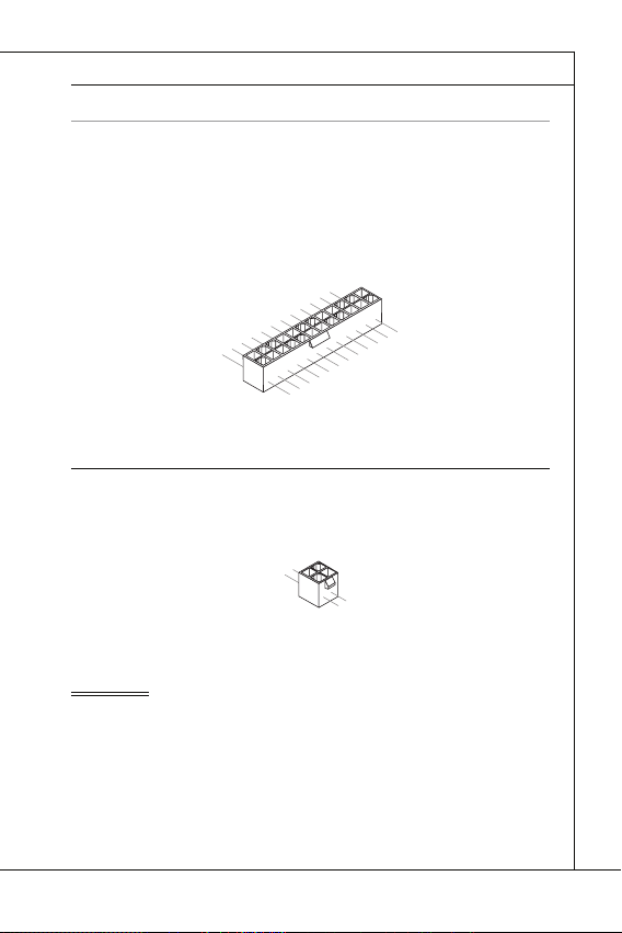
Русский
РАЗЪЕМ ПИТАНИЯ
24-контактный разъем питания ATX: JPWR1
V
1
4-контактный разъем питания ATX: JPWR2
V
1
Внимание
РАЗЪЕМ ПИТАНИЯ
24-контактный разъем питания ATX: JPWR1
Этот разъем позволяет подключить 24-контактный коннектор питания ATX.
Для его подключения убедитесь, что коннектор и контакты разъема правильно
сориентированы. Затем плотно вставьте его в разъем на системной плате.
Вы также можете использовать 20-контактный ATX блок питания. При
использовании 20-контактного разъема, подключайте его вдоль контактов 1 и 13.
2.+3.3V
11.+12V
10.+12V
9.5VSB
8.PWR OK
7.Ground
6.+5V
5.Ground
4.+5V
3.Ground
2.+3.3V
1.+3.3V
17.Ground
16.PS-ON#
15.Ground
14.-12V
13.+3.3
4-контактный разъем питания ATX: JPWR2
Этот разъем питания используется для обеспечения питания процессора.
.Ground
2.Ground
Внимание
Убедитесь в том, что все разъемы подключены к источникам питания ATX для
•
стабильной работы системной платы.
Для стабильности системы настоятельно рекомендуется использовать источник
•
питания на 350 Вт (и выше).
22.+5V
21.+5V
20.Res
19.Ground
18.Ground
3.+12V
4.+12
24.Ground
23.+5V
Ru-7
Page 90

MS-7618 Системная плата
ЗАДНЯЯ ПАНЕЛЬ
Порт мыши/клавиатуры
Последовательный порт
Порт VGA
Порт USB
Разъем LAN
LED
Цвет
Состояние LED
Описание
Аудио разъемы
Порт
мыши
Линейный
вход
Порт USB
Порт
клавиатуры
Порт VGA
Разъем
LAN
Порт USB
Последовательный
порт
Линейный
выход
Микрофон
MS-7618 Системная плата
▍
ЗАДНЯЯ ПАНЕЛЬ
Линейный
Порт
мыши
Последовательный
порт
Порт
клавиатуры
▶
Порт мыши/клавиатуры
Стандартные разъемы DIN PS/2
интерфейсом PS/2
▶
Последовательный порт
Данный разъем является высокоскоростным последовательным портом связи
16550A с 16-байтной передачей FIFO. К этому разъему можно непосредственно
подключить последовательное устройство.
▶
Порт VGA
Разъем DB15 для подключения монитора.
▶
Порт USB
USB порт (Universal Serial Bus) позволяет подключать такие USB устройства, как
клавиатура, мышь и т.д.
▶
Разъем LAN
Стандартный разъем RJ-45 для подключения к
локальной вычислительной сети (LAN). К нему
подключается кабель локальной сети.
LED
Цвет
Лев. Жёлт. Нет LAN соединение не установлено.
Прав.
Зелён. Нет Скорость передачи 10 Мб/с.
Оранж. Есть Скорость передачи 1000 Мб/с.
Аудио разъемы
▶
Эти разъемы используются для подключения звуковых устройств. Разъемы,
выполняющие разные функции, имеют различные цвета.
Вход аудио (Голубой) - Линейный вход, используется для подключения
■
внешего CD проигрывателя, магнитофона или других звуковых
устройств.
Выход аудио (Зелёный) - Линейный выход для подключения наушников
■
или колонок.
Микрофон (Розовый) - Разъем для подключения микрофона.
■
®
.
Состояние LED
Есть(постоянно) LAN соединение установлено.
Есть(ярче & мигает) Связь с другим компьютером по LAN.
Есть Скорость передачи 100 Мб/с.
Порт VGA
Описание
Порт USB
®
для подключения мыши/клавиатуры с
Разъем
вход
LAN
Линейный
выход
Микрофон
Порт USB
Жёлт. Зелён./ Оранж.
Ru-8
Page 91

Русский
КОННЕКТОРЫ
Разъем Serial ATA: SATA1~2
F
l
o
p
p
y
D
M
S
I
F
l
o
p
p
y
D
M
S
I
K
d
k
l
k
d
k
f
k
k
k
f
d
k
k
l
d
d
f
k
k
k
s
d
d
f
d
d
f
a
s
d
k
a
d
f
-
d
d
f
d
d
a
d
d
f
d
f
d
d
d
d
d
f
a
d
f
a
d
k
j
a
s
j
d
k
d
f
d
f
a
s
d
d
d
f
f
a
s
d
f
d
d
d
d
d
d
d
f
d
a
s
f
d
a
s
a
s
d
f
a
s
d
a
s
d
a
s
d
d
d
d
d
d
d
f
a
s
a
s
d
f
s
d
f
f
s
d
f
a
d
f
f
f
a
s
d
f
f
f
d
f
Внимание
Разъем датчика открывания корпуса: JCI1
U
d
КОННЕКТОРЫ
Разъем Serial ATA: SATA1~2
Данный разъем является высокоскоростным портом интерфейса Serial ATA.
Любой разъем Serial ATA может соединяться с одним устройством Serial ATA.
l
k
k
d
f
k
k
f
d
k
f
d
d
f
k
d
d
f
d
f
k
d
d
d
s
l
a
d
k
d
f
k
-
d
s
d
k
a
d
f
k
K
f
d
f
d
d
a
d
d
f
d
d
k
d
d
d
f
d
k
d
d
s
d
d
f
a
d
j
f
s
d
d
d
f
a
d
s
j
a
a
d
s
s
k
d
a
a
f
a
d
f
f
s
d
d
a
s
d
a
f
f
d
d
d
d
s
d
f
a
d
d
d
f
s
d
s
d
f
d
a
f
f
f
d
f
d
s
s
d
f
a
s
d
a
s
f
f
a
f
d
a
D
y
p
l
p
k
k
o
d
f
l
k
k
f
k
F
I
d
f
d
d
f
k
d
S
f
d
d
f
k
d
d
d
l
a
d
s
f
k
k
d
-
d
s
d
k
M
f
K
a
d
k
f
d
d
f
d
d
d
d
a
f
k
d
d
d
d
f
d
d
k
d
s
d
d
j
f
a
d
f
d
d
s
a
d
d
f
j
s
a
d
a
k
s
s
a
d
a
f
a
d
f
f
s
d
a
d
D
s
d
f
a
d
f
d
d
y
d
s
f
d
a
f
d
d
d
p
s
d
s
d
f
f
f
d
a
f
d
p
f
d
s
s
d
f
a
s
o
d
a
s
f
l
f
a
f
d
F
I
a
S
D
M
y
p
p
o
l
F
I
S
M
Внимание
Избегайте, пожалуйста, резких изгибов кабеля Serial ATA. В противном случае
могут возникнуть потери данных при передаче.
Разъем датчика открывания корпуса: JCI1
К этому коннектору подключается кабель датчика, установленного в корпусе.
При открывании корпуса его механизм активизируется. Система запоминает это
событие и выдает предупреждение на экран. Предупреждение можно отключить
в настройках BIOS.
2
.
G
1
r
.
C
o
u
I
N
n
T
R
Ru-9
Page 92

MS-7618 Системная плата
Разъем питания вентиляторов: SYSFAN1~2
r
Коннекторы передней панели: JFP1
h
D
MS-7618 Системная плата
▍
Разъем питания вентиляторов: SYSFAN1~2
Разъемы питания вентиляторов поддерживают вентиляторы с питанием +12В.
При подключении необходимо помнить, что красный провод подключается к шине
+12В, черный - к земле GND. Если на системной плате установлена микросхема
аппаратного мониторинга, необходимо использовать специальные вентиляторы с
датчиками скорости для реализации функции управления вентиляторами.
1
.
2
G
.
r
+
3
o
1
.
u
S
2
n
e
V
d
n
s
o
Коннекторы передней панели: JFP1
Эти коннекторы используются для подключения кнопок и индикаторов,
расположенных на передней панели корпуса. Коннектор JFP1 соответствует
руководству Intel
®
Front Panel I/O Connectivity Design.
Power Switch
Power LED
10.NoPin
4.-
2.+
8.-
6.+
7.+
5.-
3.-
1.+
HDD LE
9.Reserv ed
Reset Switc
Ru-10
Page 93

Разъем USB передней панели: JUSB1 / JUSB2
C
1
n
Внимание
Выносной разъем аудио: JAUD1
1
L
Разъем USB передней панели: JUSB1 / JUSB2
Разъем, соответствует спецификации Intel® I/O Connectivity Design, идеально
подходит для подключения таких высокоскоростных периферийных устройств, как
USB HDD, цифровые камеры, MP3 плееры, принтеры, модемы и им подобные.
0
.
8
U
.
S
G
6
B
r
.
o
U
4
2
.
V
Внимание
Помните, что во избежание повреждений, контакты VCC и GND должны быть
правильно подключены.
Выносной разъем аудио: JAUD1
Этот коннектор позволяет подключить выносной разъем аудио на передней
панели и соответствует руководству Intel
0
.
8
H
.
e
N
6
o
.
M
4
P
.
I
i
P
C
2
R
.
D
G
E
e
r
S
o
E
u
N
n
d
C
O
u
S
.
U
C
a
n
t
e
E
C
n
B
d
S
D
B
+
D
C
-
d
P
h
o
n
e
D
c
e
t
i
o
n
#
9
.
N
7
o
.
G
5
P
.
r
U
i
o
3
u
.
S
U
1
®
Front Panel I/O Connectivity Design.
t
e
c
t
i
o
n
B
S
.
n
d
D
V
B
C
+
D
-
Выносная планка USB 2.0
(опционально)
9
.
H
7
e
.
S
5
a
E
.
d
H
3
1
.
M
N
P
.
e
M
S
h
a
E
o
I
d
C
I
C
L
n
_
P
S
R
h
E
o
N
n
e
R
e
D
Русский
Ru-11
Page 94

MS-7618 Системная плата
Разъем TPM Модуля: JTPM1
1
2
0
3
Разъем параллельного порта: JLPT1
MS-7618 Системная плата
▍
Разъем TPM Модуля: JTPM1
Данный разъем подключается к модулю TPM (Trusted Platform Module)(опционально).
За более подробной информацией и назначениями обращайтесь к описанию
модуля TPM.
4
1
.
G
2
1
.
r
G
o
0
u
.
r
8
N
o
n
.
u
o
d
5
6
n
V
P
.
S
4
.
3
.
3
.
3
V
S
t
a
Разъем параллельного порта: JLPT1
Этот коннектор используется для подключения опциональной планки
параллельного порта. Параллельный порт - это стандартный порт для принтера.
Он поддерживает режимы EPP (усовершенствованный параллельный порт) и
ECP (параллельный порт с дополнительными возможностями).
1
6
1
4
1
.
G
2
1
.
G
0
.
r
8
G
o
.
u
r
L
6
o
P
.
u
P
T
4
2
.
A
n
I
_
.
N
E
S
I
R
T
L
R
I
#
F
N
#
D
#
d
i
P
n
e
o
r
i
w
a
e
l
V
I
r
R
P
Q
o
w
e
n
r
d
b
y
p
o
w
e
r
1
2
6
2
.
N
4
2
.
o
G
2
P
2
r
.
G
o
0
1
8
.
G
.
G
r
o
u
r
o
u
n
d
n
d
d
#
i
n
u
.
r
G
o
n
u
d
r
o
n
u
d
r
o
n
u
d
n
d
n
d
1
3
1
1
.
9
P
.
P
7
R
.
P
5
N
R
.
P
3
N
R
.
P
1
D
N
R
.
2
D
R
N
S
1
D
T
0
B
#
1
3
1
.
L
1
P
.
9
L
C
.
P
L
7
5
.
L
3
.
L
P
.
L
C
P
C
C
1
9
1
7
1
.
P
5
.
P
R
.
P
N
R
N
R
D
N
D
D
4
3
F
C
P
.
L
P
R
l
o
2
.
A
R
D
5
r
C
a
a
P
m
d
a
C
d
d
C
a
d
e
s
e
c
k
2
2
3
.
1
.
B
U
C
K
N
D
7
6
e
r
a
d
e
d
r
s
e
d
s
s
r
&
s
e
d
s
r
t
5
.
P
E
S
#
&
e
S
Y
d
s
a
d
s
&
s
L
C
t
a
a
d
t
&
T
a
p
a
d
i
p
t
n
a
a
i
n
t
p
a
2
i
n
p
1
i
n
Ru-12
Page 95

Русский
Разъем S/PDIF-Out: JSP1
Разъем S/PDIF-Out: JSP1
Этот разъем используется для подключения интерфейса S/PDIF (Sony & Philips
Digital Interconnect Format) для передачи звука в цифровом формате.
3
.
G
2
.
r
S
o
1
P
u
.
V
n
D
d
C
I
F
C
Выносная планка S/PDIF
(опционально)
Ru-13
Page 96

MS-7618 Системная плата
ПЕРЕМЫЧКИ
Перемычка очистки CMOS: JBAT1
JBAT1
1 11
Внимание
MS-7618 Системная плата
▍
ПЕРЕМЫЧКИ
Перемычка очистки CMOS: JBAT1
На плате установлена CMOS память с питанием от батарейки, хранящая данные
о конфигурации системы. С помощью памяти CMOS, система автоматически
загружается каждый раз при включении. Если у вас возникает необходимость
сбросить конфигурацию системы (очистить CMOS), воспользуйтесь этой
перемычкой.
JBAT1 Хранение
Внимание
Очистка CMOS производится соединением контактов 2-3 при отключенной
системе. Затем следует вернуться к соединению контактов 1-2. Избегайте очистки
CMOS при работающей системе: это повредит системную плату.
настроек
Сброс
настроек
Ru-14
Page 97

Русский
СЛОТЫ
Слот PCI (Peripheral Component Interconnect)
Внимание
Маршрутизация запросов прерывания PCI
Order1 Order2 Order3 Order4
СЛОТЫ
Слот PCI (Peripheral Component Interconnect)
Слот PCI позволяет установить карты LAN, SCSI, USB и другие дополнительные
карты расширения, которые соответствуют спецификации PCI.
32-bit PCI слот
Внимание
Перед установкой или извлечением карт расширения убедитесь, что кабель
питания отключен от электрической сети. Прочтите документацию на карту
расширения и выполните необходимые аппаратные или програмные установки
для данной платы, такие как перемычки, переключатели или конфигурацию
BIOS.
Маршрутизация запросов прерывания PCI
IRQ - сокращение от interrupt request (line) - линия запроса прерывания,
аппаратная линия, по которой устройства могут посылать сигнал прерывания
микропроцессору. Обычное подключение PCI IRQ к контактам шины PCI показано
ниже:
PCI Slot1 INT B# INT C# INT D# INT A#
Order1 Order2 Order3 Order4
Ru-15
Page 98

MS-7618 Системная плата
НАСТРОЙКА BIOS
Внимание
MS-7618 Системная плата
▍
НАСТРОЙКА BIOS
В этой главе приводятся основные сведения о режиме настройки BIOS (BIOS
SETUP), который позволяет установить оптимальную конфигурацию системы.
Этот режим может потребоваться в следующих случаях:
Во время загрузки системы появляется сообщение об ошибке с
■
требованием запустить BIOS SETUP.
Требуется заменить заводские настройки на собственные.
■
Внимание
Для улучшения работы системы содержимое каждого из разделов BIOS,
•
рассматриваемое в данной главе, постоянно совершенствуется. Поэтому, для
новых версий BIOS оно может несколько отличаться от данного описания,
которое сможет служить в качестве ориентира.
При загрузке, в первой, после объема памяти строке, выводится обозначение
•
BIOS . Обычно оно имеет следующий формат:
1ая буква соответствует изготовителю BIOS ( A = AMI, W = AWARD и P
= PHOENIX).
Следующие 4 цифры соответствуют номеру модели.
Следующая буква обозначает поставщика чипсета (I = Intel, N = Nvidia,
A = AMD, и V = VIA).
2 следующие буквы обозначают заказчика MS = стандартный заказчик.
V1.0 соответствует номеру версии BIOS.
020110 - дата выпуска BIOS.
Ru-16
A7618IMS V1.0 020110 где:
Page 99

Русский
Вход в режим настройки
Press DEL to enter SETUP
(Нажмите DEL для входа в SETUP)
Режим настройки
Main Menu (Главное меню)
Подменю
Подробная справка <F1>
Вход в режим настройки
Включите питание компьютера. При этом запустится процедура POST (Тест
включения питания). Когда на экране появится приведенное ниже сообщение,
нажмите клавишу <DEL> для входа в режим настройки.
Press DEL to enter SETUP
(Нажмите DEL для входа в SETUP)
Если сообщение исчезло, а вы не успели нажать клавишу, перезапустите систему,
выключив и снова включив питание, или нажав кнопку RESET. Можно, также,
перезапустить систему, нажав одновременно клавиши <Ctrl>, <Alt>, и <Delete>.
Режим настройки
Войдя в режим настройки, вы сразу увидите Главное меню.
Main Menu (Главное меню)
Главное меню содержит список настроек, которые вы можете изменить. Для
выбора можно использовать клавиши со стрелками ( ↑↓ ) . Справка о выбранной
настройке отображается в нижней части экрана.
Подменю
Если вы обнаружите, что слева от пункта меню имеется знак правого указателя
это означает наличие подменю, содержащего дополнительные настройки
которые можно сделать в этом пункте. Используйте управляющие клавиши ( ↑
↓ ) для выбора , а затем нажмите <Enter> чтобы вызвать подменю. Далее можно
использовать управляющие клавиши для ввода параметров и перемещения по
пунктам подменю. Чтобы вернуться в главное меню, просто нажмите <Esc>.
Подробная справка <F1>
В режиме настройки BIOS имеется возможность получения подробной справки.
Ее можно вызвать из любого меню простым нажатием <F1>. В окне справки будут
перечислены все возможные настройки в выбранном пункте меню. Нажмите
<Esc> для выключения окна справки.
Ru-17
Page 100

MS-7618 Системная плата
The Main Menu (Главное меню)
Standard CMOS Features (Стандартные функции CMOS)
Advanced BIOS Features (Дополнительные функции BIOS)
Integrated Peripherals (Встроенные периферийные устройста)
Power Management Setup (Настройка управления питанием)
H/W Monitor (Монитор аппаратной части)
BIOS Setting Password (Пароль доступа к настройкам BIOS)
Cell Menu (Меню узла “Cell”)
M-Flash
MS-7618 Системная плата
▍
The Main Menu (Главное меню)
При входе в режим настройки BIOS на экране отображается Главное меню.
Главное меню позволяет выбрать функции настройки и имеет два варианта
выхода. Для перемещения по пунктам используются клавиши со стрелками и <Enter> для подтверждения или входа в подменю.
▶
Standard CMOS Features (Стандартные функции CMOS)
Это меню позволяет установить основные параметры конфигурации системы
(дату, время и т.п.).
▶
Advanced BIOS Features (Дополнительные функции BIOS)
Это меню используется для настройки специальных функций.
▶
Integrated Peripherals (Встроенные периферийные устройста)
Это меню используется для настройки параметров встроенных периферийных
устройств.
▶
Power Management Setup (Настройка управления питанием)
Это меню позволяет задать параметры управления питанием системы.
▶
H/W Monitor (Монитор аппаратной части)
Этот пункт отображает состояние аппаратной части ПК.
▶
BIOS Setting Password (Пароль доступа к настройкам BIOS)
Это меню используется, чтобы задать пароль.
▶
Cell Menu (Меню узла “Cell”)
Это меню позволяет управлять тактовыми частотами и напряжениями при разгоне
системы.
▶
M-Flash
Используется для чтения/ прошивки BIOS с внешнего накопителя (только FAT/
FAT32).
Ru-18
 Loading...