

Page 1
Copyright Notice
The material in this document is the intellectual property of MICRO-STAR
INTERNATIONAL. We take every care in the preparation of this document, but no
guarantee is given as to the correctness of its contents. Our products are under
continual improvement and we reserve the right to make changes without notice.
Trademarks
All trademarks in this manual are properties of their respective owners.
MSI® is registered trademark of Micro-Star Int’l Co.,Ltd.
■
NVIDIA® is registered trademark of NVIDIA Corporation.
■
ATI® is registered trademark of AMD Corporation.
■
AMD® is registered trademarks of AMD Corporation.
■
Intel® is registered trademarks of Intel Corporation.
■
Windows® is registered trademarks of Microsoft Corporation.
■
AMI® is registered trademark of American Megatrends Inc.
■
Award® is a registered trademark of Phoenix Technologies Ltd.
■
Sound Blaster® is registered trademark of Creative Technology Ltd.
■
Realtek® is registered trademark of Realtek Semiconductor Corporation.
■
JMicron® is registered trademark of JMicron Technology Corporation.
■
Netware® is registered trademark of Novell, Inc.
■
Lucid® is trademark of LucidLogix Technologies, Ltd.
■
VIA® is registered trademark of VIA Technologies, Inc.
■
ASMedia® is registered trademark of ASMedia Technology Inc.
■
iPad, iPhone, and iPod are trademarks of Apple Inc.
■
Qualcomm Atheros and Killer are trademarks of Qualcomm Atheros Inc.
■
Revision History
Revision Revision History Date
V7.0 First release 203/0
V7.
Add A58M-E33 204/02
Preface
G52-7720
Page 2
Safety Instructions
Preface
Always read the safety instructions carefully.
■
Keep this User’s Manual for future reference.
■
Keep this equipment away from humidity.
■
Lay this equipment on a reliable at surface before setting it up.
■
The openings on the enclosure are for air convection hence protects the
■
equipment from overheating. DO NOT COVER THE OPENINGS.
Make sure the voltage of the power source is at 0/220V before connecting the
■
equipment to the power inlet.
Place the power cord such a way that people can not step on it. Do not place
■
anything over the power cord.
Always Unplug the Power Cord before inserting any add-on card or module.
■
All cautions and warnings on the equipment should be noted.
■
Never pour any liquid into the opening that can cause damage or cause electrical
■
shock.
If any of the following situations arises, get the equipment checked by service
■
personnel:
The power cord or plug is damaged.
◯
Liquid has penetrated into the equipment.
◯
The equipment has been exposed to moisture.
◯
The equipment does not work well or you can not get it work according to
◯
User’s Manual.
The equipment has been dropped and damaged.
◯
The equipment has obvious sign of breakage.
◯
DO NOT LEAVE THIS EQUIPMENT IN AN ENVIRONMENT ABOVE 60oC
■
(40oF), IT MAY DAMAGE THE EQUIPMENT.
Battery Information
European Union:
Batteries, battery packs, and accumulators should not be disposed
of as unsorted household waste. Please use the public collection
system to return, recycle, or treat them in compliance with the local
regulations.
Taiwan:
For better environmental protection, waste batteries should be
廢電池請回收
collected separately for recycling or special disposal.
California, USA:
The button cell battery may contain perchlorate material and requires
special handling when recycled or disposed of in California.
For further information please visit:
http://www.dtsc.ca.gov/hazardouswaste/perchlorate/
CAUTION: There is a risk of explosion, if battery is incorrectly replaced.
Replace only with the same or equivalent type recommended by the manufacturer.
2
Page 3
FCC-B Radio Frequency Interference Statement
This equipment has been tested and found to comply with the limits for a Class
B digital device, pursuant to Part 5 of the FCC Rules. These limits are designed
to provide reasonable protection against harmful interference in a residential
installation. This equipment generates, uses and can radiate radio frequency
energy and, if not installed and used in accordance with the instructions, may cause
harmful interference to radio communications. However, there is no guarantee that
interference will not occur in a particular installation. If this equipment does cause
harmful interference to radio or television reception, which can be determined
by turning the equipment o and on, the user is encouraged to try to correct the
interference by one or more of the measures listed below.
Reorient or relocate the receiving antenna.
◯
Increase the separation between the equipment and receiver.
◯
Connect the equipment into an outlet on a circuit dierent from that to which
◯
the receiver is connected.
Consult the dealer or an experienced radio/television technician for help.
◯
Notice
The changes or modications not expressly approved by the party responsible for
compliance could void the user’s authority to operate the equipment.
Notice 2
Shielded interface cables and A.C. power cord, if any, must be used in order to
comply with the emission limits.
VOIR LA NOTICE D’INSTALLATION AVANT DE RACCORDER AU RESEAU.
Micro-Star International
MS-772
This device complies with Part 5 of the FCC Rules. Operation is subject to the
following two conditions:
this device may not cause harmful interference, and
)
this device must accept any interference received, including interference that
2)
may cause undesired operation.
Preface
CE Conformity
Hereby, Micro-Star International CO., LTD declares that this device is
in compliance with the essential safety requirements and other relevant
provisions set out in the European Directive.
3
Page 4
Radiation Exposure Statement
Preface
This equipment complies with FCC radiation exposure limits set forth for an
uncontrolled environment. This equipment and its antenna should be installed and
operated with minimum distance 20 cm between the radiator and your body. This
equipment and its antenna must not be co-located or operating in conjunction with
any other antenna or transmitter.
European Community Compliance Statement
The equipment complies with the RF Exposure Requirement 999/59/EC, Council
Recommendation of 2 July 999 on the limitation of exposure of the general public
to electromagnetic elds (0–300GHz). This wireless device complies with the R&TTE
Directive.
Taiwan Wireless Statements
無線設備警告聲明
經型式認證合格之低功率射頻電機,非經許可,公司、商號或使用者均不得擅自變更
頻率、加大功率或變更原設計之特性及功能。
低功率射頻電機之使用不得影響飛航安全及干擾合法通信;經發現有干擾現象時,應
立即停用,並改善至無干擾時方得繼續使用。前項合法通信,指依電信法規定作業之
無線電通信。低功率射頻電機須忍受合法通信或工業、科學及醫療用電波輻射性電機
設備之干擾。
警告使用者:這是甲類資訊產品,在居住的環境中使用時,可能會造成無線電干擾,在
這種情況下,使用者會被要求採取某些適當的對策。
Japan VCCI Class B Statement
クラス B 情報技術装置
この装置は、情報技術装置等電波障害自主規制協議会(VCCI)の基準に基づくクラ
スB情報技術装置です。この装置が家庭内でラジオやテレビジョン受信機に近接して
使われると、受信障害を引き起こすことがあります。取扱説明書にしたがって正し
い取り扱いをしてください。
Korea Warning Statements
당해 무선설비는 운용중 전파혼신 가능성이 있음
Chemical Substances Information
In compliance with chemical substances regulations, such as the EU REACH
Regulation (Regulation EC No. 907/2006 of the European Parliament and the
Council), MSI provides the information of chemical substances in products at:
http://www.msi.com/html/popup/csr/evmtprtt_pcm.html
4
Page 5
产品中有毒有害物质或元素名称及含量
根据中国<电子信息产品污染控制管理办法>
有毒有害物质或元素
部件名称
印刷电路板组件* ☓ 〇 〇 〇 〇 〇
电池**
外部信号连接头 ☓ 〇 〇 〇 〇 〇
线材 ☓ 〇 〇 〇 〇 〇
〇: 表示该有毒有害物质在该部件所有均质材料中的含量均在SJ/T363-2006标
准规定的限量要求下。
☓: 表示该有毒有害物质至少在该部件的某一均质材料中的含量超出SJ/T363-
2006标准规定的限量要求,但所有部件都符合欧盟RoHS要求。
* 印刷电路板组件: 包括印刷电路板及其构成的零部件。
** 电池本体上如有环保使用期限标识,以本体标识为主。
上述有毒有害物质或元素清单会依型号之部件差异而有所增减。
■
產品部件本体上如有环保使用期限标识,以本体标识为主。
■
铅
(Pb)汞(Hg)镉(Cd)
☓ 〇 〇 〇 〇 〇
六价铬
(Cr6+)
多溴联苯
(PBB)
多溴二苯醚
(PBDE)
Preface
5
Page 6
WEEE Statement
Preface
WEEE (Waste Electrical and Electronic Equipment)
ENGLISH
To protect the global environment and as an environmentalist, MSI must
remind you that...
Under the European Union (“EU”) Directive on Waste Electrical and
Electronic Equipment, Directive 2002/96/EC, which takes eect on August 3, 2005,
products of “electrical and electronic equipment” cannot be discarded as municipal
wastes anymore, and manufacturers of covered electronic equipment will be
obligated to take back such products at the end of their useful life. MSI will comply
with the product take back requirements at the end of life of MSI-branded products
that are sold into the EU. You can return these products to local collection points.
DEUTSCH
Hinweis von MSI zur Erhaltung und Schutz unserer Umwelt
Gemäß der Richtlinie 2002/96/EG über Elektro- und Elektronik-Altgeräte dürfen
Elektro- und Elektronik-Altgeräte nicht mehr als kommunale Abfälle entsorgt werden.
MSI hat europaweit verschiedene Sammel- und Recyclingunternehmen beauftragt,
die in die Europäische Union in Verkehr gebrachten Produkte, am Ende seines
Lebenszyklus zurückzunehmen. Bitte entsorgen Sie dieses Produkt zum gegebenen
Zeitpunkt ausschliesslich an einer lokalen Altgerätesammelstelle in Ihrer Nähe.
FRANÇAIS
En tant qu’écologiste et an de protéger l’environnement, MSI tient à rappeler ceci...
Au sujet de la directive européenne (EU) relative aux déchets des équipement
électriques et électroniques, directive 2002/96/EC, prenant eet le 3 août 2005,
que les produits électriques et électroniques ne peuvent être déposés dans les
décharges ou tout simplement mis à la poubelle. Les fabricants de ces équipements
seront obligés de récupérer certains produits en n de vie. MSI prendra en compte
cette exigence relative au retour des produits en n de vie au sein de la communauté
européenne. Par conséquent vous pouvez retourner localement ces matériels dans
les points de collecte.
РУССКИЙ
Компания MSI предпринимает активные действия по защите окружающей
среды, поэтому напоминаем вам, что....
В соответствии с директивой Европейского Союза (ЕС) по предотвращению
загрязнения окружающей среды использованным электрическим и электронным
оборудованием (директива WEEE 2002/96/EC), вступающей в силу 3
августа 2005 года, изделия, относящиеся к электрическому и электронному
оборудованию, не могут рассматриваться как бытовой мусор, поэтому
производители вышеперечисленного электронного оборудования обязаны
принимать его для переработки по окончании срока службы. MSI обязуется
соблюдать требования по приему продукции, проданной под маркой MSI на
территории EC, в переработку по окончании срока службы. Вы можете вернуть
эти изделия в специализированные пункты приема.
6
Page 7

ESPAÑOL
MSI como empresa comprometida con la protección del medio ambiente,
recomienda:
Bajo la directiva 2002/96/EC de la Unión Europea en materia de desechos y/o
equipos electrónicos, con fecha de rigor desde el 3 de agosto de 2005, los
productos clasicados como “eléctricos y equipos electrónicos” no pueden ser
depositados en los contenedores habituales de su municipio, los fabricantes de
equipos electrónicos, están obligados a hacerse cargo de dichos productos al
termino de su período de vida. MSI estará comprometido con los términos de
recogida de sus productos vendidos en la Unión Europea al nal de su periodo de
vida. Usted debe depositar estos productos en el punto limpio establecido por el
ayuntamiento de su localidad o entregar a una empresa autorizada para la recogida
de estos residuos.
NEDERLANDS
Om het milieu te beschermen, wil MSI u eraan herinneren dat….
De richtlijn van de Europese Unie (EU) met betrekking tot Vervuiling van Electrische
en Electronische producten (2002/96/EC), die op 3 Augustus 2005 in zal gaan
kunnen niet meer beschouwd worden als vervuiling. Fabrikanten van dit soort
producten worden verplicht om producten retour te nemen aan het eind van hun
levenscyclus. MSI zal overeenkomstig de richtlijn handelen voor de producten
die de merknaam MSI dragen en verkocht zijn in de EU. Deze goederen kunnen
geretourneerd worden op lokale inzamelingspunten.
SRPSKI
Da bi zaštitili prirodnu sredinu, i kao preduzeće koje vodi računa o okolini i prirodnoj
sredini, MSI mora da vas podesti da…
Po Direktivi Evropske unije (“EU”) o odbačenoj ekektronskoj i električnoj opremi,
Direktiva 2002/96/EC, koja stupa na snagu od 3. Avgusta 2005, proizvodi koji
spadaju pod “elektronsku i električnu opremu” ne mogu više biti odbačeni kao običan
otpad i proizvođači ove opreme biće prinuđeni da uzmu natrag ove proizvode na
kraju njihovog uobičajenog veka trajanja. MSI će poštovati zahtev o preuzimanju
ovakvih proizvoda kojima je istekao vek trajanja, koji imaju MSI oznaku i koji su
prodati u EU. Ove proizvode možete vratiti na lokalnim mestima za prikupljanje.
POLSKI
Aby chronić nasze środowisko naturalne oraz jako rma dbająca o ekologię, MSI
przypomina, że...
Zgodnie z Dyrektywą Unii Europejskiej (“UE”) dotyczącą odpadów produktów
elektrycznych i elektronicznych (Dyrektywa 2002/96/EC), która wchodzi w życie 3
sierpnia 2005, tzw. “produkty oraz wyposażenie elektryczne i elektroniczne “ nie
mogą być traktowane jako śmieci komunalne, tak więc producenci tych produktów
będą zobowiązani do odbierania ich w momencie gdy produkt jest wycofywany z
użycia. MSI wypełni wymagania UE, przyjmując produkty (sprzedawane na terenie
Unii Europejskiej) wycofywane z użycia. Produkty MSI będzie można zwracać w
wyznaczonych punktach zbiorczych.
Preface
7
Page 8

TÜRKÇE
Preface
Çevreci özelliğiyle bilinen MSI dünyada çevreyi korumak için hatırlatır:
Avrupa Birliği (AB) Kararnamesi Elektrik ve Elektronik Malzeme Atığı, 2002/96/EC
Kararnamesi altında 3 Ağustos 2005 tarihinden itibaren geçerli olmak üzere,
elektrikli ve elektronik malzemeler diğer atıklar gibi çöpe atılamayacak ve bu
elektonik cihazların üreticileri, cihazların kullanım süreleri bittikten sonra ürünleri geri
toplamakla yükümlü olacaktır. Avrupa Birliği’ne satılan MSI markalı ürünlerin kullanım
süreleri bittiğinde MSI ürünlerin geri alınması isteği ile işbirliği içerisinde olacaktır.
Ürünlerinizi yerel toplama noktalarına bırakabilirsiniz.
ČESKY
Záleží nám na ochraně životního prostředí - společnost MSI upozorňuje...
Podle směrnice Evropské unie (“EU”) o likvidaci elektrických a elektronických
výrobků 2002/96/EC platné od 3. srpna 2005 je zakázáno likvidovat “elektrické
a elektronické výrobky” v běžném komunálním odpadu a výrobci elektronických
výrobků, na které se tato směrnice vztahuje, budou povinni odebírat takové výrobky
zpět po skončení jejich životnosti. Společnost MSI splní požadavky na odebírání
výrobků značky MSI, prodávaných v zemích EU, po skončení jejich životnosti. Tyto
výrobky můžete odevzdat v místních sběrnách.
MAGYAR
Annak érdekében, hogy környezetünket megvédjük, illetve környezetvédőként
fellépve az MSI emlékezteti Önt, hogy ...
Az Európai Unió („EU”) 2005. augusztus 3-án hatályba lépő, az elektromos
és elektronikus berendezések hulladékairól szóló 2002/96/EK irányelve szerint
az elektromos és elektronikus berendezések többé nem kezelhetőek lakossági
hulladékként, és az ilyen elektronikus berendezések gyártói kötelessé válnak az
ilyen termékek visszavételére azok hasznos élettartama végén. Az MSI betartja
a termékvisszavétellel kapcsolatos követelményeket az MSI márkanév alatt az
EU-n belül értékesített termékek esetében, azok élettartamának végén. Az ilyen
termékeket a legközelebbi gyűjtőhelyre viheti.
ITALIANO
Per proteggere l’ambiente, MSI, da sempre amica della natura, ti ricorda che….
In base alla Direttiva dell’Unione Europea (EU) sullo Smaltimento dei Materiali
Elettrici ed Elettronici, Direttiva 2002/96/EC in vigore dal 3 Agosto 2005, prodotti
appartenenti alla categoria dei Materiali Elettrici ed Elettronici non possono più
essere eliminati come riuti municipali: i produttori di detti materiali saranno obbligati
a ritirare ogni prodotto alla ne del suo ciclo di vita. MSI si adeguerà a tale Direttiva
ritirando tutti i prodotti marchiati MSI che sono stati venduti all’interno dell’Unione
Europea alla ne del loro ciclo di vita. È possibile portare i prodotti nel più vicino
punto di raccolta
8
Page 9

Contents
English ......................................................................................
Motherboard Specications ....................................................................................2
Back Panel ..............................................................................................................4
APU & Heatsink Installation ....................................................................................5
Memory Installation .................................................................................................7
Internal Connectors.................................................................................................8
BIOS Setup .............................................................................................................25
한국어 .......................................................................................3
메인보드 사양 .........................................................................................................32
후면 패널 .................................................................................................................34
APU 및 히트싱크 설치 ............................................................................................35
메모리 설치 .............................................................................................................37
내장 커넥터 .............................................................................................................38
BIOS 설정 ...............................................................................................................45
Français ....................................................................................5
Spécications ..........................................................................................................52
Panneau Arrière ......................................................................................................54
Installation d'APU et son ventilateur .......................................................................55
Installation de mémoire ...........................................................................................57
Connecteurs internes ..............................................................................................58
Conguration BIOS .................................................................................................65
Deutsch ....................................................................................7
Spezikationen........................................................................................................72
Rücktafel-Übersicht.................................................................................................74
APU & Kühlkörper Einbau.......................................................................................75
Speicher ..................................................................................................................77
Interne Anschlüsse .................................................................................................78
BIOS Setup .............................................................................................................85
Русский ....................................................................................9
Характеристики материнской платы....................................................................92
Задняя панель .......................................................................................................94
Установка APU и радиатора .................................................................................95
Установка памяти ..................................................................................................97
Внутренние разъемы ............................................................................................98
Настройка BIOS ...................................................................................................05
Preface
9
Page 10

简体中文 .................................................................................
主板规格 ................................................................................................................2
Preface
后置面板 ................................................................................................................4
APU 和风扇的安装 ................................................................................................5
内存安装 ................................................................................................................7
内部接口 ................................................................................................................8
BIOS 设置 .............................................................................................................25
繁體中文 .................................................................................3
主機板規格 ............................................................................................................32
背板 .......................................................................................................................34
安裝 APU 與散熱風扇 ...........................................................................................35
安裝記憶體 ............................................................................................................37
內建接頭 ................................................................................................................38
BIOS 設定 .............................................................................................................45
日本語 .....................................................................................5
マザーボードの仕様 ..............................................................................................52
I/Oパネル ..............................................................................................................54
APUおよびヒートシンクの装着 ...........................................................................55
メモリの装着 ........................................................................................................57
内部コネクター .....................................................................................................58
BIOSの設定 ...........................................................................................................65
0
Page 11
English
BAT1
Top: LAN J ack
Bott om: USB 2 .0 port s
Top: mou se
Bott om: key board
T:Line -In
M:Li ne-O ut
B:Mi c
VGA por t
USB2 .0 port s
HDMI p ort
JAUD 1
JTPM 1
PCI_ E1
PCI_ E2
PCI1
JBAT1
JUSB _PW2
CPUFA N
SYSF
AN
1
JPWR
1
DIMM 1
DIMM 2
JPWR 2
JCOM 1 JUSB 2 JUSB1
JUSB _P 1W
JFP1
JFP2
SATA1 S ATA2
SATA3_ 4
J 1CI
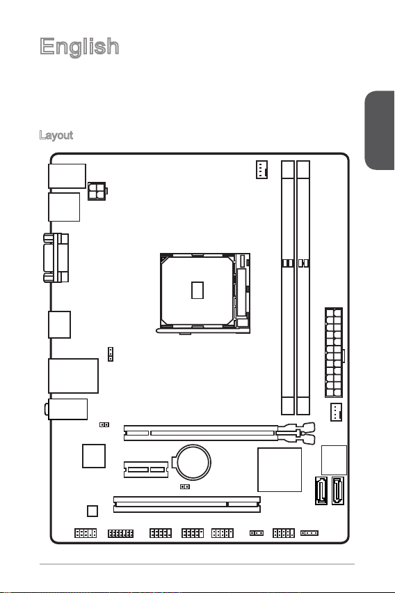
Thank you for choosing the A55M-E33/ A58M-E33 Series (MS-772 v7.X) Micro-ATX
motherboard. The A55M-E33/ A58M-E33 Series motherboards are based on AMD
A55/ A58 chipset for optimal system eciency. Designed to t the advanced AMD
FM2+/ FM2 processor, the A55M-E33/ A58M-E33 Series motherboards deliver a
high performance and professional desktop platform solution.
Layout
English
Page 12
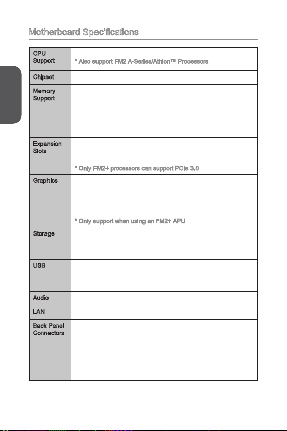
Motherboard Specications
CPU
Support
Chipset AMD A55/ A58■
English
Memory
Support
Expansion
Slots
Graphics x VGA port, supporting a maximum resolution of
Storage AMD A55/ A58 Chipset
USB AMD A55/ A58 Chipset
Audio Realtek® ALC887 Codec■
LAN Realtek® RTL8G Gigabit LAN controller■
Back Panel
Connectors
AMD Socket FM2+ A-Series/Athlon™ Processors*
■
* Also support FM2 A-Series/Athlon™ Processors
2x DDR3 memory slots supporting up to 32GB
■
Supports DDR3 233(OC)/ 866/ 600/ 333 MHz
■
Dual channel memory architecture
■
Supports non-ECC, un-buered memory
■
Supports AMD Memory Prole (AMP)
■
Supports Extreme Memory Prole (XMP)
■
x PCIe 3.0 x6 slot*
■
x PCIe 2.0 x slot
■
x PCI slot
■
* Only FM2+ processors can support PCIe 3.0
■
920x200@60Hz, 24bpp
x HDMI port, supporting a maximum resolution of
■
4096x260@24Hz, 36bpp*/ 3840x260@30Hz, 36bpp*/
920x200@20Hz, 36bpp and 920x200@60Hz, 36bpp
* Only support when using an FM2+ APU
■
4x SATA 3Gb/s ports
Supports RAID 0, RAID and RAID 0
-
■
8x USB 2.0 ports (4 ports on the back panel, 4 ports
available through the internal USB connectors)
x PS/2 keyboard port
■
x PS/2 mouse port
■
4x USB 2.0 ports
■
x VGA port
■
x HDMI port
■
x LAN (RJ45) port
■
3x audio jacks
■
2
Page 13
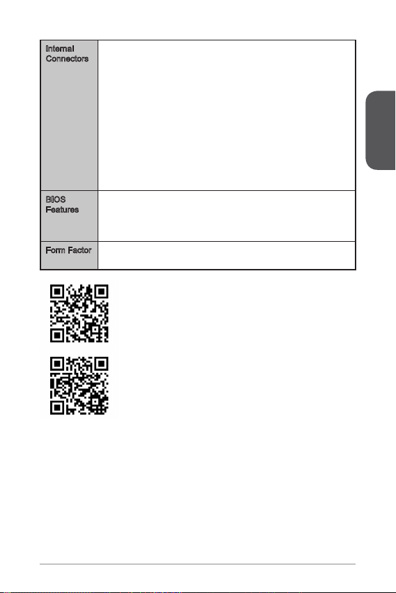
Internal
Connectors
BIOS
Features
Form Factor Micro-ATX Form Factor
x 24-pin ATX main power connector
■
x 4-pin ATX 2V power connector
■
4x SATA 3Gb/s connectors
■
2x USB 2.0 connectors (supports additional 4 USB 2.0 ports)
■
x 4-pin CPU fan connector
■
x 4-pin system fan connector
■
x Front panel audio connector
■
2x System panel connectors
■
x Chassis Intrusion connector
■
x TPM module connector
■
x Serial port connector
■
x Clear CMOS jumper
■
2x USB power jumpers
■
64 Mb ash
■
UEFI AMI BIOS
■
ACPI 5.0, PnP .0a, SM BIOS 2.7, DMI 2.0
■
Multi-language
■
■
8.9 in. x 6.8 in. (22.5 cm x 7.2 cm)
■
For the latest information about CPU, please visit
http://www.msi.com/service/cpu-support/
For more information on compatible components, please
visit http://www.msi.com/service/test-report/
English
3
Page 14
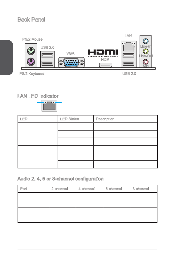
Back Panel
®
PS/2 Mouse
English
PS/2 Keyboard
USB 2.0
VGA
HDMI
LAN LED Indicator
LINK/ACT
LED
LED LED Status Description
Link/ Activity LED
Speed LED
SPEED
LED
O No link
Yellow Linked
Blinking Data activity
O 0 Mbps connection
Green 00 Mbps connection
Orange Gbps connection
Audio 2, 4, 6 or 8-channel conguration
Port 2-channel 4-channel 6-channel 8-channel
Blue Line in RS-Out RS-Out RS-Out
Green Line out FS-Out FS-Out FS-Out
Pink Mic Mic CS-Out CS-Out
Front audio - - - SS-Out
LAN
Line-In
Line-Out
Mic
USB 2.0
4
Page 15
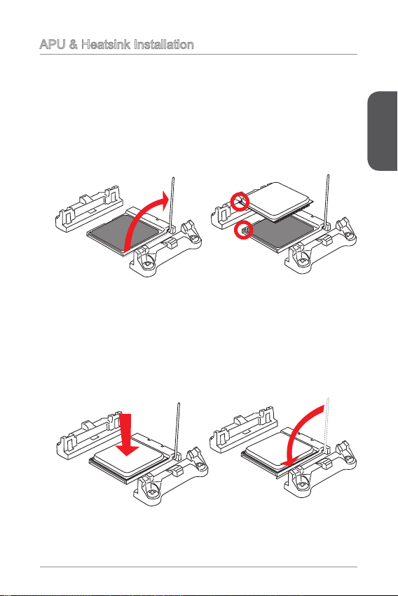
APU & Heatsink Installation
When installing a APU, always remember to install a APU heatsink. An APU heatsink
is necessary to prevent overheating and maintain system stability. Follow the steps
below to ensure correct APU and heatsink installation. Wrong installation can
damage both the APU and the motherboard.
. Pull the lever sideways away from the socket. Make sure to raise the lever up to
a 90-degree angle.
2. Look for the gold arrow of the APU. The gold arrow should point as shown in the
picture. The APU can only t in the correct orientation.
3. If the APU is correctly installed, the pins should be completely embedded into
the socket and can not be seen. Please note that any violation of the correct
installation procedures may cause permanent damages to your motherboard.
4. Press the APU down rmly into the socket and close the lever. As the APU is
likely to move while the lever is being closed, always close the lever with your
ngers pressing tightly on top of the APU to make sure the APU is properly and
completely embedded into the socket.
English
5
Page 16
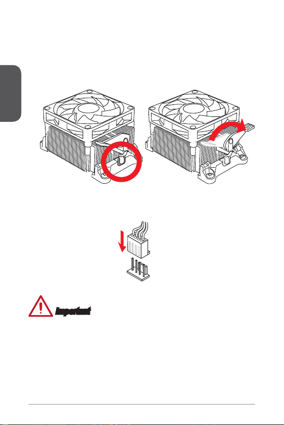
5. Locate the CPU fan connector on the motherboard.
6. Position the cooling set onto the retention mechanism. Hook one end of the clip
to hook rst.
7. Then press down the other end of the clip to fasten the cooling set on the top of
the retention mechanism. Locate the Fix Lever and lift up it.
8. Fasten down the lever.
English
9. Attach the APU Fan cable to the APU fan connector on the motherboard.
Important
While disconnecting the Safety Hook from the xed bolt, it is necessary to keep an
•
eye on your ngers, because once the Safety Hook is disconnected from the xed
bolt, the xed lever will spring back instantly.
Conrm that the APU cooler has formed a tight seal with the APU before booting
•
your system.
Please refer to the documentation in the APU cooler package for more details
•
about APU cooler installation.
6
Page 17
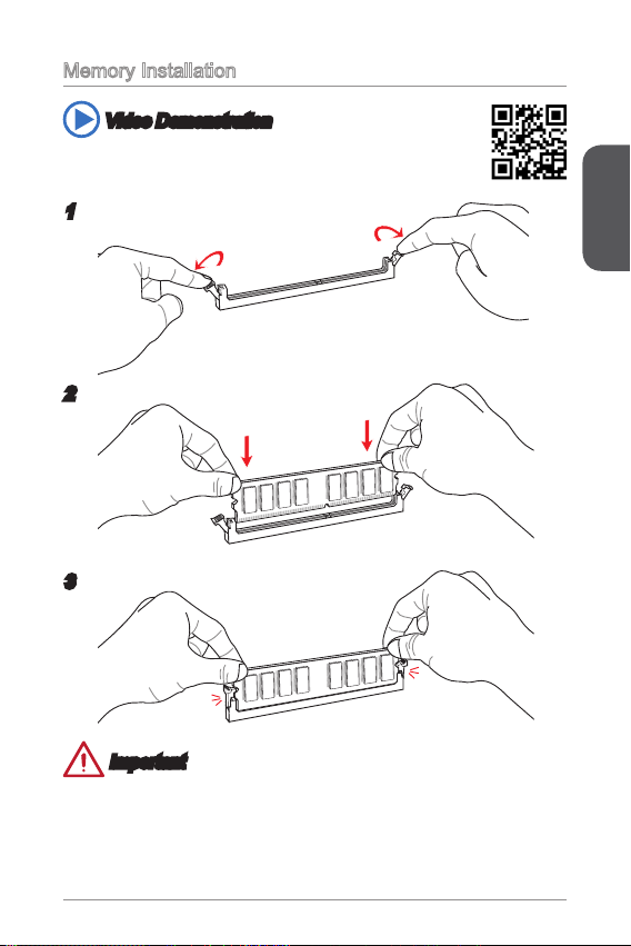
Memory Installation
Video Demonstration
Watch the video to learn how to install memories at the address below.
http://youtu.be/76yLtJaKlCQ
2
3
Important
DDR3 memory modules are not interchangeable with DDR2, and the DDR3
•
standard is not backward compatible. Always install DDR3 memory modules in
DDR3 DIMM slots.
To ensure system stability, memory modules must be of the same type and density
•
in Dual-Channel mode.
English
7
Page 18
Internal Connectors
13. +3. 3
V
1.+ 3.3
V
14. -12 V
2.+ 3.3
V
15. Gro und
3
.Gr oun d
16. PS- ON
#
4.+ 5
V
17. Gro und
5
.Gr oun d
18. Gro und
6.+ 5
V
19. Gro und
7
.Gr oun d
22. +5
V
10. +12 V
20. Res
8.P W
R O
K
23. +5
V
11
.+1 2V
21. +5
V
9.5 VSB
24. Gro und
12. +3. 3
V
4.+ 12V
2
.Gr oun d
3.+ 12V
1
.Gr oun d
1
.
D
C
D
3
.
S
O
U
T
1
0
.
N
o
P
i
n
5
.
G
r
o
u
n
d
7
.
R
T
S
9
.
R
I
8
.
C
T
S
6
.
D
S
R
4
.
D
T
R
2
.
S
I
N
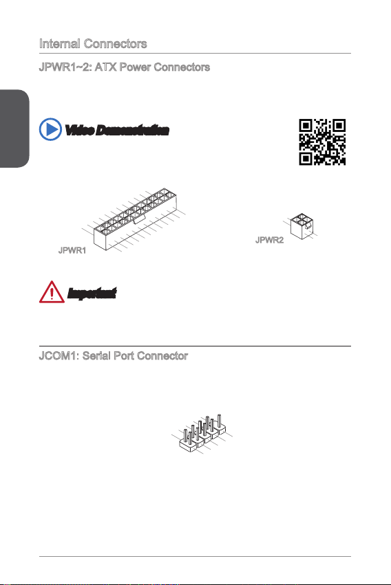
JPWR~2: ATX Power Connectors
These connectors allow you to connect an ATX power supply. To connect the ATX
power supply, align the power supply cable with the connector and rmly press the
cable into the connector. If done correctly, the clip on the power cable should be
English
hooked on the motherboard’s power connector.
Video Demonstration
Watch the video to learn how to install power supply connectors.
http://youtu.be/gkDYyR_83I4
JPWR
JPWR2
Important
Make sure that all the power cables are securely connected to a proper ATX power
supply to ensure stable operation of the motherboard.
JCOM: Serial Port Connector
This connector is a 6550A high speed communication port that sends/receives 6
bytes FIFOs. You can attach a serial device.
8
Page 19
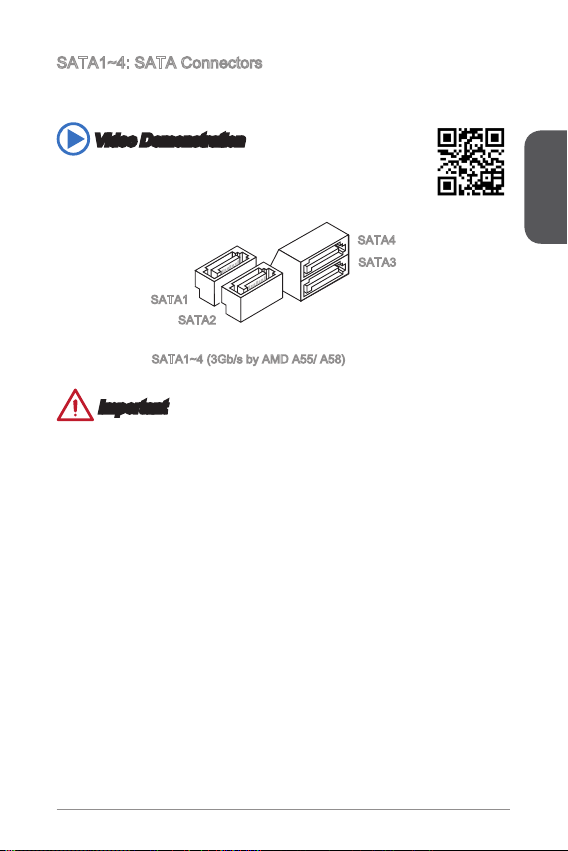
SATA~4: SATA Connectors
This connector is a high-speed SATA interface port. Each connector can connect to
one SATA device. SATA devices include disk drives (HDD), solid state drives (SSD),
and optical drives (CD/ DVD/ Blu-Ray).
Video Demonstration
Watch the video to learn how to Install SATA HDD.
http://youtu.be/RZsMpqxythc
SATA4
SATA3
SATA
SATA2
SATA~4 (3Gb/s by AMD A55/ A58)
Important
Many SATA devices also need a power cable from the power supply. Such devices
•
include disk drives (HDD), solid state drives (SSD), and optical drives (CD / DVD /
Blu-Ray). Please refer to the device’s manual for further information.
Many computer cases also require that large SATA devices, such as HDDs, SSDs,
•
and optical drives, be screwed down into the case. Refer to the manual that came
with your computer case or your SATA device for further installation instructions.
Please do not fold the SATA cable at a 90-degree angle. Data loss may result
•
during transmission otherwise.
SATA cables have identical plugs on either sides of the cable. However, it is
•
recommended that the at connector be connected to the motherboard for space
saving purposes.
English
9
Page 20
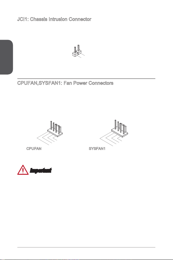
JCI: Chassis Intrusion Connector
2
.
C
I
N
T
R
U
1
.
G
r
o
u
n
d
1
.Grou nd
2.Spe ed
C
ontro
l
3.Sen s
e
4.NC
1
.Gr ou nd
2.+ 12 V
3.S en s
e
4.S pe ed
C
ont ro
l
This connector connects to the chassis intrusion switch cable. If the computer case
is opened, the chassis intrusion mechanism will be activated. The system will record
this intrusion and a warning message will ash on screen. To clear the warning, you
must enter the BIOS utility and clear the record.
English
CPUFAN,SYSFAN: Fan Power Connectors
The fan power connectors support system cooling fans with +2V. If the motherboard
has a System Hardware Monitor chipset on-board, you must use a specially designed
fan with a speed sensor to take advantage of the CPU fan control. Remember to
connect all system fans. Some system fans may not connect to the motherboard and
will instead connect to the power supply directly. A system fan can be plugged into
any available system fan connector.
CPUFAN SYSFAN
Important
Please refer to your processor’s ocial website or consult your vendor to nd
•
recommended CPU heatsink.
These connectors support Smart Fan Control with liner mode. The Command
•
Center utility can be installed to automatically control the fan speeds according to
the CPU’s and system’s temperature.
If there are not enough ports on the motherboard to connect all system fans,
•
adapters are available to connect a fan directly to a power supply.
Before rst boot up, ensure that there are no cables impeding any fan blades.
•
20
Page 21
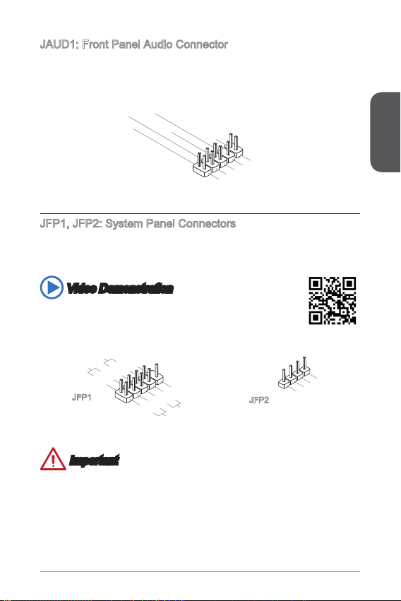
JAUD: Front Panel Audio Connector
1.M I
C L
3.M IC R
10. He ad
P
hon e
Det ec ti on
5.H ea d
P
hon e
R
7.S EN SE _SE N
D
9.H ea d
P
hon e
L
8.N o
Pi
n
6.M I
C D
ete ct io n
4.N C
2
.Gr ou nd
3.S pea ke r
4.V CC5
1.S pea ke r
2.V CC5
1.
+
3.
-
10. No
Pi
n
5.-
Res et
S
wit ch
HDD
LE
D
P
owe r
Swi tc h
P
owe r
LE
D
7.+
9.R es erv e
d
8.
-
6.
+
4.
-
2.
+
This connector allows you to connect the front audio panel located on your computer
case.
JFP, JFP2: System Panel Connectors
These connectors connect to the front panel switches and LEDs. When installing the
front panel connectors, please use the optional M-Connector to simplify installation.
Plug all the wires from the computer case into the M-Connector and then plug the
M-Connector into the motherboard.
Video Demonstration
Watch the video to learn how to Install front panel connectors.
http://youtu.be/DPELIdVNZUI
English
JFP
JFP2
Important
On the connectors coming from the case, pins marked by small triangles are
•
positive wires. Please use the diagrams above and the writing on the optional MConnectors to determine correct connector orientation and placement.
The majority of the computer case’s front panel connectors will primarily be
•
plugged into JFP.
2
Page 22
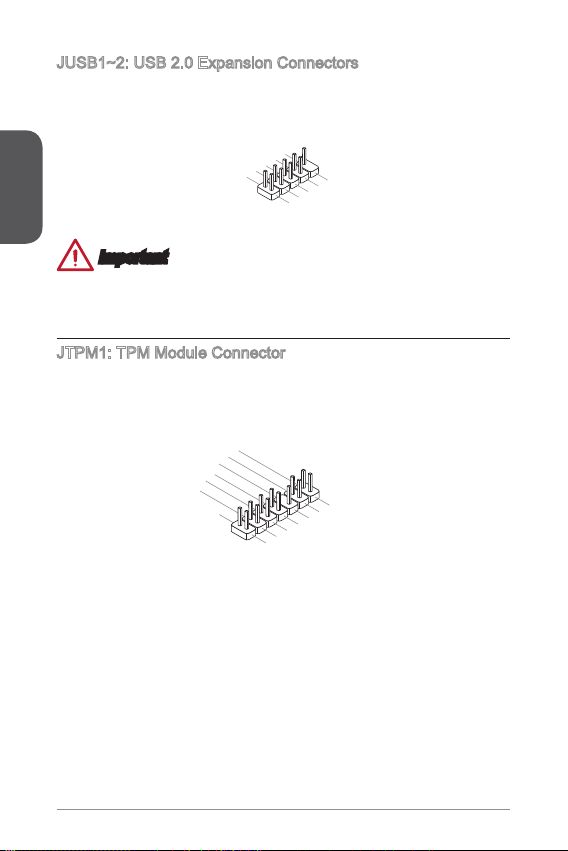
JUSB~2: USB 2.0 Expansion Connectors
1
.
V
C
C
3
.
U
S
B
0
-
1
0
.
NC
5
.
U
S
B
0
+
7
.
G
r
o
u
n
d
9
.
N
o
P
i
n
8
.
G
r
o
u
n
d
6
.
U
S
B
1
+
4
.
U
S
B
1
-
2
.
V
C
C
10. No
Pi
n
14. Groun d
8.5 V
P
owe r
12. Groun d
6.S erial
IR
Q
4.3 .3V
P
owe r
2.3 V
Sta ndby
p
owe r
1.L P
C C
loc
k
3.L P
C
Res e
t
5.L P
C a
ddr es
s &
dat a
pin 0
7.L P
C a
ddr es
s &
dat a
p
in1
9.L P
C a
ddr es
s &
dat a
pin 2
11
.LP C
a
ddr es
s &
dat a
p
in3
13. LP
C
Fra m
e
This connector is designed for connecting high-speed USB peripherals such as USB
HDDs, digital cameras, MP3 players, printers, modems, and many others.
English
Important
Note that the VCC and GND pins must be connected correctly to avoid possible
damage.
JTPM: TPM Module Connector
This connector connects to a TPM (Trusted Platform Module). Please refer to the
TPM security platform manual for more details and usages.
22
Page 23
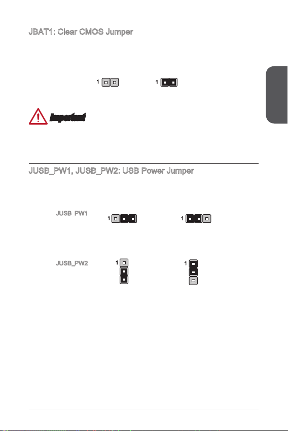
JBAT: Clear CMOS Jumper
There is CMOS RAM onboard that is external powered from a battery located on the
motherboard to save system conguration data. With the CMOS RAM, the system
can automatically boot into the operating system (OS) every time it is turned on. If
you want to clear the system conguration, set the jumpers to clear the CMOS RAM.
Keep Data Clear Data
Important
You can clear the CMOS RAM by shorting this jumper while the system is o.
Afterwards, open the jumper . Do not clear the CMOS RAM while the system is on
because it will damage the motherboard.
JUSB_PW, JUSB_PW2: USB Power Jumper
These jumpers are used to assign which USB and PS/2 ports could support “Wake
Up Event Setup” eld of BIOS.
English
JUSB_PW
(for onboard
USB connectors)
JUSB_PW2
(for back panel
USB ports &
PS/2 ports)
Support
Support
No Support (Default)
No Support (Default)
23
Page 24
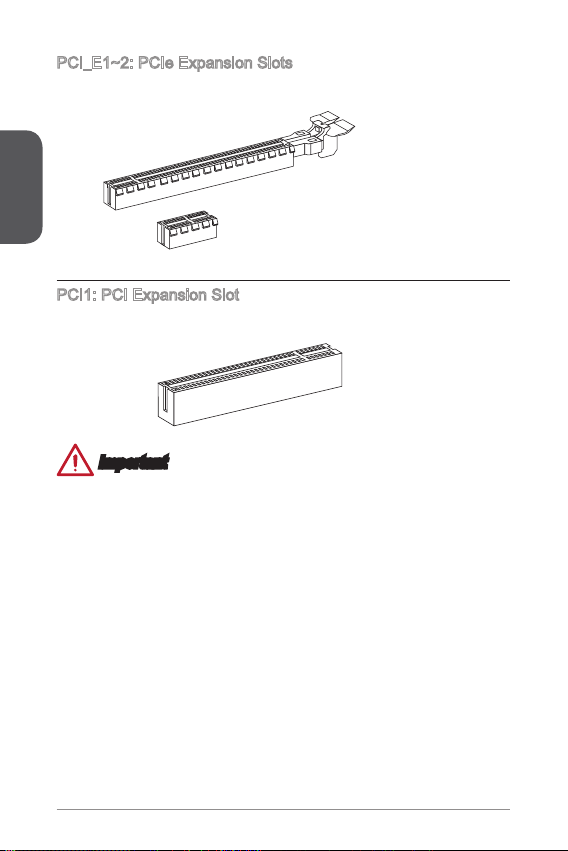
PCI_E~2: PCIe Expansion Slots
The PCIe slot supports the PCIe interface expansion card.
English
PCIe x Slot
PCIe x6 Slot
PCI: PCI Expansion Slot
The PCI slot supports the PCI interface expansion card..
PCI Slot
Important
When adding or removing expansion cards, always turn o the power supply and
unplug the power supply power cable from the power outlet. Read the expansion
card’s documentation to check for any necessary additional hardware or software
changes.
24
Page 25
BIOS Setup
The default settings oer the optimal performance for system stability in normal
conditions. You may need to run the Setup program when:
An error message appears on the screen during the system booting up, and
■
requests you to run SETUP.
You want to change the default settings for customized features.
■
Important
Please load the default settings to restore the optimal system performance and
•
stability if the system becomes unstable after changing BIOS settings. Select the
"Restore Defaults" and press <Enter> in BIOS to load the default settings.
If you are unfamiliar with the BIOS settings, we recommend that you keep the
•
default settings to avoid possible system damage or failure booting due to
inappropriate BIOS conguration.
Entering BIOS Setup
Power on the computer and the system will start the Power On Self Test (POST)
process. When the message below appears on the screen, please <DEL> key to
enter BIOS:
Press DEL key to enter Setup Menu, F to enter Boot Menu
If the message disappears before you respond and you still need to enter BIOS,
restart the system by turning the computer OFF then back ON or pressing the
RESET button. You may also restart the system by simultaneously pressing <Ctrl>,
<Alt>, and <Delete> keys.
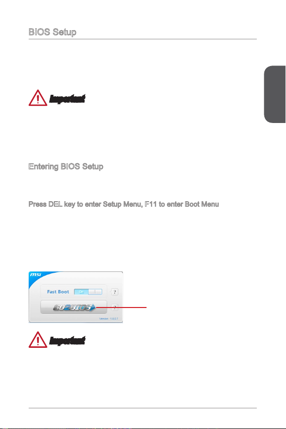
MSI additionally provides two methods to enter the BIOS setup. You can click the
“GO2BIOS” tab on “MSI Fast Boot” utility screen or press the physical “GO2BIOS"
button (optional) on the motherboard to enable the system going to BIOS setup
directly at next boot.
Click "GO2BIOS" tab on "MSI Fast
Boot" utility screen.
Important
Please be sure to install the “MSI Fast Boot” utility before using it to enter the BIOS
setup.
English
25
Page 26
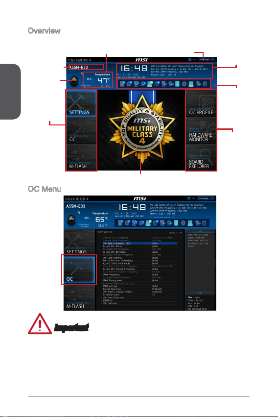
Overview
After entering BIOS, the following screen is displayed.
Model name
English
Virtual OC
Genie Button
BIOS menu
selection
Temperature monitor
OC Menu
Menu display
Language
System
information
Boot device
priority bar
BIOS menu
selection
Important
Overclocking your PC manually is only recommended for advanced users.
•
Overclocking is not guaranteed, and if done improperly, can void your warranty or
•
severely damage your hardware.
If you are unfamiliar with overclocking, we advise you to use OC Genie for easy
•
overclocking.
26
Page 27
Current CPU/ DRAM Frequency
▶
These items show the current frequencies of installed CPU and Memory. Read-only.
▶
CPU Base Frequency (MHz) [Default]
Sets the CPU Base clock. You may overclock the CPU by adjusting this value.
Please note that overclocking behavior and stability is not guaranteed. This item
appears when the installed processor supports this function.
▶
Adjust CPU Ratio [Auto]
Sets the CPU ratio that is used to determine CPU clock speed. This item can only be
changed if the processor supports this function.
▶
Adjusted CPU Frequency
Shows the adjusted CPU frequency. Read-only.
▶
Adjust CPU-NB Ratio [Auto]
Sets the CPU-NB ratio that is used to determine CPU-NB clock speed.
Adjusted CPU-NB Frequency
▶
Shows the adjusted CPU frequency. Read-only.
CPU Core Control [Auto]
▶
Change the number of CPU Core in the system. If set to "Auto", the CPU will operate
under the default number of cores. [Options: Auto, One core per processor(Core 0
Only), One core per processor(Core 2 Only), One Compute Unit(Core 0 & ), One
Compute Unit(Core 2 & 3), One core per Compute Unit(Core 0 & 2)]
AMD Turbo Core Technology [Auto]
▶
Base on AMD Turbo Core Technology, part of CPU core ratio may pop down for
providing more performance headroom for active CPU core, even AMD Cool’n’Quiet
Technology is Disabled.
[Auto] Turbo Core Technology will linked to AMD Cool’n’Quiet
Technology.
[Enabled] Enables this function.
[Disabled] Disables this function.
▶
Adjust Turbo Core Ratio [Auto]
Species the Turbo Core frequency multiplier.
▶
Adjusted Turbo Core Frequency
Shows the adjusted Turbo Core frequency. Read-only.
▶
Adjust GPU Engine Frequency [Auto]
Adjust GPU Engine Frequency.
Adjusted GPU Engine Frequency
▶
Shows the adjusted GPU Engine frequency. Read-only.
DRAM Frequency [Auto]
▶
Sets the DRAM frequency. Please note the overclocking behavior is not guaranteed.
Adjusted DRAM Frequency
▶
Shows the adjusted DRAM frequency. Read-only.
English
27
Page 28

Intel Extreme Memory Prole (XMP) [Disabled]
▶
XMP is the overclocking technology by memory module. This item will be available
when you install the memory modules that support XMP technology. When the XMP
is Enabled, the AMP will be forced to be disabled.
[Disabled] Disables this function.
[Prole ] Uses prole over-clocking settings of installed XMP memory
English
[Prole 2] Uses prole2 over-clocking settings of installed XMP memory
AMD Memory Prole (AMP) [Disabled]
▶
AMP is the overclocking technology by memory module. This item will be available
when you install the memory modules that support AMP technology. When AMP is
Enabled, the XMP will be forced to be disabled.
[Disabled] Disables this function.
[Prole ] Uses prole over-clocking settings of installed AMP memory
[Prole 2] Uses prole2 over-clocking settings of installed AMP memory
DRAM Timing Mode [Auto]
▶
Selects the memory timing mode.
[Auto] DRAM timings will be determined based on SPD (Serial Presence
[Link] Allows user to congure the DRAM timing manually for all memory
[UnLink] Allows user to congure the DRAM timing manually for respective
Advanced DRAM Conguration
▶
Press <Enter> to enter the sub-menu. This sub-menu will be activated after setting
[Link] or [Unlink] in “DRAM Timing Mode”. User can set the memory timing for each
memory channel. The system may become unstable or unbootable after changing
memory timing. If it occurs, please clear the CMOS data and restore the default
settings. (Refer to the Clear CMOS jumper/ button section to clear the CMOS data,
and enter the BIOS to load the default settings.
DRAM Voltage [Auto]
▶
Sets DRAM voltage. If set to "Auto", BIOS will set DRAM voltage automatically or
you can set it manually.
Spread Spectrum
▶
This function reduces the EMI (Electromagnetic Interference) generated by
modulating clock generator pulses.
[Enabled] Enables the spread spectrum function to reduce the EMI
[Disabled] Enhances the overclocking ability of CPU Base clock.
module.
module.
module.
module.
Detect) of installed memory modules.
channel.
memory channel.
(Electromagnetic Interference) problem.
28
Page 29
Important
If you do not have any EMI problem, leave the setting at [Disabled] for optimal
•
system stability and performance. But if you are plagued by EMI, select the value
of Spread Spectrum for EMI reduction.
The greater the Spread Spectrum value is, the greater the EMI is reduced, and
•
the system will become less stable. For the most suitable Spread Spectrum value,
please consult your local EMI regulation.
Remember to disable Spread Spectrum if you are overclocking because even a
•
slight jitter can introduce a temporary boost in clock speed which may just cause
your overclocked processor to lock up.
CPU Memory Changed Detect [Enabled]
▶
Enables or disables the system to issue a warning message during boot when the
CPU or memory has been replaced.
[Enabled] The system will issue a warning message during boot and than
[Disabled] Disables this function and keeps the current BIOS settings.
OC Retry Count
▶
When overclocking has failed, setting this item as [,3] will allow system to reboot
/ 3 times with the same overclocked conguration. If overclocking has failed every
time, the system will restore the defaults.
CPU Features
▶
Press <Enter> to enter the sub-menu.
AMD Cool’n’Quiet [Auto]
▶
Enabled or disabled AMD Cool’n’Quiet function.
[Auto] Depends on AMD Design.
[Enable] Enables AMD Cool’n’Quiet function. The Cool’n’Quiet
[Disabled] Disables this function.
needs to load the default settings for new devices.
technology can eectively and dynamically lower CPU speed
and power consumption.
Important
When adjust CPU Ratio setting then Cool’n’Quiet function will be disabled
automatically. For CPU which supports the Turbo Core Tech., please set AMD Turbo
Core Technology and AMD Cool’n’Quiet as Disabled to retain the default CPU core
speed.
SVM Mode [Enabled]
▶
Enables or disables CPU Virtualization.
[Enabled] Enables CPU Virtualization and allows a platform to run
[Disabled] Disables this function.
multiple operating systems in independent partitions. The
system can function as multiple systems virtually.
English
29
Page 30

English
Core C6 State [Enabled]
▶
Enables or disables C6 state support.
[Enabled] When the CPU enters C6 state, all cores will save
[Disabled] Disables this function.
architectural state and reduce core voltages to zero volts.
Wake up the CPU from C6 state will take a lot longer.
30
Page 31

한국어
BAT1
Top: LAN J ack
Bott om: USB 2 .0 port s
Top: mou se
Bott om: key board
T:Line -In
M:Li ne-O ut
B:Mi c
VGA por t
USB2 .0 port s
HDMI p ort
JAUD 1
JTPM 1
PCI_ E1
PCI_ E2
PCI1
JBAT1
JUSB _PW2
CPUFA N
SYSF
AN
1
JPWR
1
DIMM 1
DIMM 2
JPWR 2
JCOM 1 JUSB 2 JUSB1
JUSB _P 1W
JFP1
JFP2
SATA1 S ATA2
SATA3_ 4
J 1CI
A55M-E33/ A58M-E33 시리즈 (MS-772 v7.X) Micro-ATX 메인보드를 선택해 주셔
서 감사합니다. A55M-E33/ A58M-E33 시리즈 메인보드는 최적의 시스템 효율을 위해
AMD A55/ A58 칩셋에 기반을 둔 제품입니다. 고급 AMD FM2+/ FM2 프로세서에 적
합하게 디자인 된 A55M-E33/ A58M-E33 시리즈는 고성능과 전문적인 데스크톱 플랫
폼 솔루션을 제공합니다.
레이아웃
한국어
3
Page 32

메인보드 사양
지원되는
CPU
칩셋 AMD A55/ A58■
지원되는 메모리DDR3 메모리 슬롯 2개, 최대 32GB 지원
한국어
확장 슬롯 PCIe 3.0 x6 슬롯 개*
그래픽 VGA 포트 개, 최대 920x200@60Hz, 24bpp 해상도 지원
스토리지 AMD A55/ A58 칩셋
USB AMD A55/ A58 칩셋
오디오 Realtek® ALC887 코덱■
LAN Realtek® RTL8G Gigabit LAN 컨트롤러■
후면 패널
커넥터
AMD 소켓 FM2+ A-시리즈/Athlon™ 프로세서*
■
* FM2 A-Series/Athlon™ 프로세서도 지원함
■
DDR3 233(OC)/ 866/ 600/ 333 MHz 지원
■
듀얼 채널 메모리 지원
■
non-ECC, un-buered 메모리 지원
■
AMD Memory Prole (AMP) 지원
■
Extreme Memory Prole (XMP) 지원
■
■
PCIe 2.0 x 슬롯 개
■
PCI 슬롯 개
■
* FM2+ 프로세서만이 PCIe 3.0을 지원
■
HDMI 포트 개, 최대 4096x260@24Hz, 36bpp*/
■
3840x260@30Hz, 36bpp*/ 920x200@20Hz, 36bpp 및
920x200@60Hz, 36bpp 해상도 지원
* FM2+ APU 사용시에만 지원
■
SATA 3Gb/s 포트 4개
RAID 0, RAID 및 RAID 0 지원
-
■
USB 2.0 포트 8개 (후면 패널에 4 포트, 내부 USB 커넥터를
통해 4 포트 사용)
PS/2 키보드 포트 개
■
PS/2 마우스 포트 개
■
USB 2.0 포트 4개
■
VGA 포트 개
■
HDMI 포트 개
■
LAN (RJ45) 포트 개
■
오디오 잭 3개
■
32
Page 33

내장 커넥터 24 핀 ATX 메인 전원 커넥터 개
BIOS 기능 64 Mb 플래시
폼 팩터 Micro-ATX 폼 팩터
■
4 핀 ATX 2V 전원 커넥터 개
■
SATA 3Gb/s 커넥터 4개
■
USB 2.0 커넥터 2개 (외 USB 2.0 4포트 지원)
■
4 핀 CPU 팬 커넥터 개
■
4 핀 시스템 팬 커넥터 개
■
전면 패널 오디오 커넥터 개
■
시스템 패널 커넥터 2개
■
섀시 침입 커넥터 개
■
TPM 모듈 커넥터 개
■
시리얼 포트 커넥터 개
■
CMOS 클리어 점퍼 개
■
USB 전원 점퍼 2개
■
■
UEFI AMI BIOS
■
ACPI 5.0, PnP .0a, SM BIOS 2.7, DMI 2.0
■
다국어
■
■
8.9 in. x 6.8 in. (22.5 cm x 7.2 cm)
■
CPU에 대한 최신 정보는
http://www.msi.com/service/cpu-support/를 참조하세요.
호환 가능한 부품에 대한 자세한 정보는
http://www.msi.com/service/test-report/를 참조하세요.
한국어
33
Page 34

후면 패널
®
PS/2 마우스
USB 2.0
한국어
VGA
PS/2 키보드
HDMI
LAN LED 표시등
LINK/ACT
LED
LED LED 상태 조건
Link/ Activity LED
(링크/ 통신 LED)
Speed LED
(속도 LED)
SPEED
LED
꺼짐
노란색 LAN이 올바르게 연결되었습니다.
깜빡임
꺼짐 0 Mbps 속도로 연결되었습니다.
녹색 00 Mbps 속도로 연결되었습니다.
오렌지색 Gbps 속도로 연결되었습니다.
LAN이 올바르게 연결되지 않았
습니다.
컴퓨터가 LAN으로 정상적인 통신
중입니다.
오디오 2, 4, 6 또는 8 채널 구성 도표
포트 2 채널 4 채널 6 채널 8 채널
파란색 라인 입력 RS-출력 RS-출력 RS-출력
회색 라인 출력 FS-출력 FS-출력 FS-출력
핑크 마이크 마이크 CS-출력 CS-출력
전면 오디오 - - - SS-출력
LAN
라인 입력
라인 출력
마이크
USB 2.0
34
Page 35

APU 및 히트싱크 설치
APU 설치시, APU 히트싱크를 반드시 설치하세요. APU 히트싱크는 과열을 방지하고
시스템 성능을 유지하는데 꼭 필요합니다.아래의 순서에 따라 APU 및 히트싱크를 정
확하게 설치하세요. 잘못 설치할 경우 CPU와 메인보드가 손상될수 있습니다.
. 레버를 소켓에서 비스듬히 당깁니다. 레버를 90도까지 올립니다.
2. APU의 금색 화살표를 찾습니다. 금색 화살표가 그림과 같이 가리키고 있어야 합
니다. APU는 올바른 한 쪽 방향으로만 끼워집니다.
3. APU가 올바로 설치되면, 핀이 소켓에 완전히 끼워져서 보이지 않게 됩니다. 올바
른 설치 절차를 따르지 않으면 메인보드가 영구적으로 손상될 수 있습니다.
4. APU를 소켓 안으로 꽉 눌러 넣고 레버를 닫습니다. 레버를 닫는 동안 APU가 움
직일 우려가 있기때문에, 레버를 닫을 때는 항상 손으로 APU 의 상단을 꽉 눌러
APU가 소켓안에 제대로 완전히 끼워지도록 해야합니다.
한국어
35
Page 36

5. CPU 팬 커넥터를 메인보드 위에 놓습니다.
6. 쿨러 세트를 고정 위치에 올려놓습니다. 먼저 클립의 한쪽 끝을 사용하여 겁니다.
7. 그리고 나서 클립의 다른 쪽 끝을 눌러 쿨러 세트를 고정 위치의 상단에 고정합니
다. 고정 레버를 찾아 위로 올립니다.
8. 레버를 아래로 눌러 고정합니다.
한국어
9. APU 팬 케이블을 메인보드의 APU 팬 커넥터에 연결합니다.
중요사항
안전 훅이 고정 볼트에서 분리되는 즉시 고정 레버가 다시 튀어 오르기때문에 고정
•
볼트에서 안전 훅을 분리할 때는 부상에 주의하세요.
시스템을 켜기 전에 APU 쿨러가 단단히 설치되었는지 확인합니다.
•
APU 팬 설치에 대한 자세한 내용은 APU 팬 패키지에 있는 설명서를 참조하세요.
•
36
Page 37

메모리 설치
데모 동영상
메모리 설치에 대한 동영상을 참조하려면 아래의 웹사이트를 방문하
세요.
http://youtu.be/76yLtJaKlCQ
2
3
한국어
중요사항
DDR3 메모리 모듈은 DDR2와 서로 호환되지 않으며 ,표준 DDR3는 하위호환이 되
•
지 않습니다.항상 DDR3 DIMM 슬롯에 DDR3 메모리 모듈을 설치해야 합니다.
시스템의 안정성을 확보하기 위하여 듀얼 채널 모드에서는 타입과 용량이 동일한
•
메모리 모듈을 사용해야 합니다.
37
Page 38

내장 커넥터
13. +3. 3
V
1.+ 3.3
V
14. -12 V
2.+ 3.3
V
15. Gro und
3
.Gr oun d
16. PS- ON
#
4.+ 5
V
17. Gro und
5
.Gr oun d
18. Gro und
6.+ 5
V
19. Gro und
7
.Gr oun d
22. +5
V
10. +12 V
20. Res
8.P W
R O
K
23. +5
V
11.+ 12V
21. +5
V
9.5 VSB
24. Gro und
12. +3. 3
V
4.+ 12V
2
.Gr oun d
3.+ 12V
1
.Gr oun d
1
.
D
C
D
3
.
S
O
U
T
1
0
.
N
o
P
i
n
5
.
G
r
o
u
n
d
7
.
R
T
S
9
.
R
I
8
.
C
T
S
6
.
D
S
R
4
.
D
T
R
2
.
S
I
N
JPWR~2: ATX 전원 커넥터
이 커넥터를 사용하여 ATX 전원 공급 장치를 연결할 수 있습니다. ATX 전원 공급 장
치를 연결하려면 커넥터에 전원 공급 케이블을 정렬하고 케이블을 커넥터 안쪽으로 꼭
눌러줍니다. 만약 정확하게 장착하였다면 전원 케이블의 클립이 메인보드의 전원 커넥
터에 꼭 맞게 걸리게 됩니다.
데모 동영상
전원 공급 장치 커넥터 설치에 대한 동영상을 참조하려면 아래의 사이
트를 방문하세요.
한국어
http://youtu.be/gkDYyR_83I4
JPWR
JPWR2
중요사항
모든 전원 케이블이 ATX 전원 공급 장치에 올바르게 연결되어 메인보드가 안정적으로
작동하는지 확인하세요.
JCOM: 시리얼 포트 커넥터
이 커넥터는 6550A 고속 통신 포트로서 6 바이트의 FIFO를 송수신합니다. 시리얼
장치를 연결할 수 있습니다.
38
Page 39

SATA~4: SATA 커넥터
이 커넥터는 고속 SATA 인터페이스 포트에 사용됩니다.각 커넥터는 하나의 SATA 장
치에 연결할수 있습니다. SATA 장치는 디스크 드라이브(HDD), 솔리드 스테이트 드라
이브(SSD)및 옵티컬 드라이브 (CD/ DVD/ 블루 레이)를 포함합니다.
데모 동영상
SATA HDD 설치에 대한 동영상을 참조하려면 아래의 웹사이트를 방
문하세요.
http://youtu.be/RZsMpqxythc
SATA4
SATA3
SATA
SATA2
SATA~4 (AMD A55/ A58로 3Gb/s 지원)
중요사항
디스크 드라이브 (HDD),솔리드 스테이트 드라이브 (SSD) 및 옵티컬 드라이브 (CD /
•
DVD / 블루 레이) 와 같은 다수의 SATA 장치는 전원 공급 장치에 연결된 전원 케이
블도 필요합니다. 자세한 내용은 해당 기기 메뉴얼을 참조하세요.
다수의 컴퓨터 케이스는 HDD, SSD, 옵티컬 드라이브와 같은 대형 SATA 장치가 케
•
이스 안쪽 하단에 고정되어 있도록 요구합니다.설치에 대한 자세한 설명은 컴퓨터
케이스나 SATA 장치와 함께 제공되는 메뉴얼을 참조하세요.
SATA 케이블을 90도로 꺽지 마세요. 그럴 경우 전송 중 데이터가 손상될 수 있습
•
니다.
SATA 케이블의 양쪽 모두에 동일한 플러그가 있지만 공간 절약을 위해 플랫 커넥터
•
를 메인보드에 연결할것을 권장합니다.
한국어
39
Page 40

JCI: 섀시 침입 커넥터
2
.
C
I
N
T
R
U
1
.
G
r
o
u
n
d
1
.Grou nd
2.Spe ed
C
ontro
l
3.Sen s
e
4.NC
1.G ro und
2.+ 12 V
3.S en s
e
4.S pe ed
C
ont ro
l
이 커넥터는 섀시 침입 스위치 케이블에 연결됩니다. 컴퓨터 케이스가 열리는 경우, 섀
시 침입 메커니즘이 활성화됩니다. 시스템이 이 상태를 기록하고 화면에 경고 메시지
가 나타납니다. 경고를 지우려면, BIOS 유틸리티에서 레코드를 지워야 합니다.
한국어
CPUFAN,SYSFAN: 팬 전원 커넥터
팬 전원 커넥터는 +2V의 시스템 쿨링 팬을 지원합니다. 메인보드에 시스템 하드웨어
모니터 칩셋이 온보드 되어 있는 경우 CPU 팬 제어를 활용하기 위하여 속도 센서가 있
는 특별히 디자인된 팬을 사용해야 합니다. 시스템 팬은 전부 연결하세요. 만일 시스템
팬을 메인보드에 전부 연결할 수 없을 경우, 전원 공급기에 직접 연결하세요.
CPUFAN SYSFAN
중요사항
프로세서 공식 웹사이트나 판매점에서 권장하는 CPU 히트싱크를 사용하세요.
•
이 커넥터는 라이너 모드에서 스마트 팬 제어를 지원합니다. CPU 및 시스템의 실
•
제 온도에 따라 팬의 속도를 자동으로 제어하는 Command Center 유틸리티를 설치
할 수 있습니다.
만일 시스템 팬을 메인보드의 포트에 전부 연결할수 없을 경우,어댑터를 사용하여
•
팬을 전원 공급기에 직접 연결하세요.
처음으로 부팅할 때, 케이블이 팬 블레이드를 방해하지 않도록 확인하세요.
•
40
Page 41

JAUD: 전면 패널 오디오 커넥터
1.M I
C L
3.M IC R
10. He ad
P
hon e
Det ec ti on
5.H ea d
P
hon e
R
7.S EN SE _SE N
D
9.H ea d
P
hon e
L
8.N o
Pi
n
6.M I
C D
ete ct io n
4.N C
2
.Gr ou nd
3.S pea ke r
4.V CC5
1.S pea ke r
2.V CC5
1.
+
3.
-
10. No
Pi
n
5.-
Res et
S
wit ch
HDD
LE
D
P
owe r
Swi tc h
P
owe r
LE
D
7.+
9.R es erv e
d
8.
-
6.
+
4.
-
2.
+
이 커넥터를 사용하여 컴퓨터 케이스에 있는 전면 오디오 패널을 연결할 수 있습니다.
JFP, JFP2: 시스템 패널 커넥터
이 커넥터는 전면 패널 스위치 및 LED에 연결됩니다. 전면 패널 커넥터 설치를 간편히
하기 위하여 옵션인 M-커넥터를 사용하세요. 컴퓨터 케이스로 부터 모든 선을 M-커넥
터에 연결한 다음 M-커넥터를 메인보드에 연결하세요.
데모 동영상
전면 패널 커넥터 설치에 대한 동영상을 참조하려면 아래의 웹사이트
를 방문하세요.
http://youtu.be/DPELIdVNZUI
한국어
JFP
JFP2
중요사항
케이스쪽 커넥터 위의 작은 삼각형 표기를 한 핀들은 양극(+)을 표시합니다.윗 그
•
림과 같이 옵션인 M-커넥터에 제시된 표기에 따라 정확한 연결 방향과 위치를 확
인하세요.
컴퓨터 케이스의 대다수 전면 패널 커넥터는 JFP에 우선적으로 연결됩니다.
•
4
Page 42

JUSB~2: USB 2.0 확장 커넥터
1
.
V
C
C
3
.
U
S
B
0
-
1
0
.
NC
5
.
U
S
B
0
+
7
.
G
r
o
u
n
d
9
.
N
o
P
i
n
8
.
G
r
o
u
n
d
6
.
U
S
B
1
+
4
.
U
S
B
1
-
2
.
V
C
C
10. No
Pi
n
14. Groun d
8.5 V
P
owe r
12. Groun d
6.S erial
IR
Q
4.3 .3V
P
owe r
2.3 V
Sta ndby
p
owe r
1.L P
C C
loc
k
3.L P
C
Res e
t
5.L P
C a
ddr es
s &
dat a
pin 0
7.L P
C a
ddr es
s &
dat a
p
in1
9.L P
C a
ddr es
s &
dat a
pin 2
11
.LP C
a
ddr es
s &
dat a
pin 3
13. LP
C
Fra m
e
이 커넥터는 USB HDD,디지컬 카메라, MP3 플레이어,프린터, 모뎀 등과 같은 고속
USB 주변 장치를 연결하도록 디자인 되었습니다.
한국어
중요사항
VCC 및 GND의 핀을 정확히 연결하여야 손상을 방지할수 있습니다.
JTPM: TPM 모듈 커넥터
이 커넥터는 TPM (Trusted Platform Module) 모듈에 연결됩니다. 자세한 내용과 사용
법은 TPM 보안 플랫폼 설명서를 참조하세요.
42
Page 43

JBAT: CMOS 클리어 점퍼
보드에 시스템 구성 데이터를 유지하기 위해 외부 배터리로부터 전원을 공급 받는
CMOS RAM이 있습니다. CMOS RAM의 경우, 시스템을 켤 때마다 시스템이 OS를 자
동으로 부팅할 수 있도록 합니다. 시스템 구성을 지우려면 점퍼를 아래와 같이 설정하
여 CMOS RAM을 지우세요.
데이터 유지 데이터 지우기
중요사항
시스템이 꺼져 있을 때 점퍼를 단락시켜 CMOS RAM을 지울수 있습니다. 그 다음,점
퍼를 분리합니다.시스템이 켜져 있는 동안에는 CMOS RAM을 지우지 마세요. 메인보
드가 손상될수 있습니다.
JUSB_PW, JUSB_PW2: USB 전원 점퍼
이 점퍼들은 각각의 USB & PS/2 포트가 바이오스의 “Wake Up Event Setup“ 기능을
지원 가능하도록 설정 합니다.
한국어
JUSB_PW
(온보드 USB 커
넥터용)
JUSB_PW2
(후면 패널 USB
포트 및 PS/2 포
트용)
지원
지원
지원하지 않음 (기본 설정)
지원하지 않음 (기본 설정)
43
Page 44

PCI_E~2: PCIe 확장 슬롯
PCIe 슬롯은 PCIe 인터페이스 확장 카드를 지원합니다.
PCIe x6 슬롯
한국어
PCIe x 슬롯
PCI: PCI 확장 슬롯
PCI 슬롯은 PCI 인터페이스 확장 카드를 지원합니다.
PCI 슬롯
중요사항
확장 카드를 추가하거나 제거할 때 먼저 전원을 끄거나 전원 코드를 콘센트에서 뽑으
세요.확장 카드에 대해 필요한 하드웨어나 소프트웨어 변경에 대하여 알려면 확장카
드 설명서를 읽으세요.
44
Page 45

BIOS 설정
기본 설정은 일반적으로 최적의 시스템 안정성을 제공합니다. 다음과 같은 경우, 설치
프로그램을 실행합니다.
시스템 부팅시 오류 메시지가 나타나고 SETUP 프로그램 실행을 요구하는 경우.
■
사용자의 요구에 따라 기본 설정을 변경하려는 경우.
■
중요사항
BIOS 설정을 변경한 후 시스템이 불안정 할 경우, 기본 설정을 로드하여 최적의
•
시스템 성능과 안정성을 복원하세요. BIOS에서 "기본값 복원" 항목을 선택하고
<Enter>를 누르면 기본 설정을 로드할 수 있습니다.
BIOS 설정에 익숙하지 않은 경우, 기본 설정으로 유지하세요. 그렇지 않은 경우, 시
•
스템 손상이나 부팅 오류가 발생할 수 있습니다.
설정 들어가기
컴퓨터를 켜면 시스템이 POST (Power On Self Test) 프로세스를 시작합니다. 화면에
아래의 메시지가 표시되면, <DEL> 키를 눌러 설정을 시작합니다.
Press DEL key to enter Setup Menu, F to enter Boot Menu
(DEL을 누르면 설정 메뉴를, F을 누르면 부팅 메뉴를 시작합니다.)
위 메시지를 보지 못했거나 BIOS로 들어가지 못했다면, 시스템을 껐다 다시 켜거나
RESET 버튼을 눌러 다시 시작합니다. 또한 <Ctrl>, <Alt> 및 <Delete> 키를 동시에 눌
러 시스템을 다시 시작할 수도 있습니다.
MSI는 BIOS 설정 화면으로 이동하는 두가지 방법을 추가적으로 제공합니다. "MSI
Fast Boot" 유틸리티 화면에서 "GO2BIOS" 탭을 클릭하거나 메인보드에서“GO2BIOS"
버튼 (옵션)을 누르면 다음 부팅시 시스템이 BIOS 설정 화면으로 직접 이동합니다.
"MSI Fast Boot" 유틸리티 화면에
서 "GO2BIOS" 탭을 클릭합니다.
중요사항
“MSI Fast Boot” 유틸리티를 사용하여 BIOS 설정 화면으로 이동하기 전에 이 유틸리
티를 설치하였는지 확인하세요.
한국어
45
Page 46

개요
BIOS를 시작하면 아래의 화면이 표시됩니다.
모델 명
Virtual OC
Genie 버튼
BIOS 선택
한국어
메뉴
온도 모니터
OC 메뉴
메뉴 디스플레이
언어
시스템 정보
부팅 장치 우
선순위 바
BIOS 선택
메뉴
중요사항
이 항목은 고급 사용자만을 위한 항목입니다.
•
오버클로킹은 보증하지 않습니다. 부적절하게 작동하였을 경우 보증이 무효화 되며
•
컴퓨터 하드웨어가 심각하게 손상될수 있습니다.
오버클로킹에 익숙하지 않은 경우, OC Genie를 사용하여 보다 쉽게 오버클로킹 할
•
것을 권장합니다.
46
Page 47

Current CPU/ DRAM Frequency
▶
이 항목은 설치된 CPU 및 메모리의 현재 주파수를 표시합니다. (읽기 전용)
▶
CPU Base Frequency (MHz) [Default]
이 항목은 CPU 베이스 클럭을 설정할 수 있습니다. 값을 조절하여 CPU를 오버클럭할
수 있습니다. 단, 오버클로킹의 작동이나 안정성은 보증하지 않습니다. 이 항목은 설치
된 프로세서가 이 기능을 지원하는 경우 나타납니다.
▶
Adjust CPU Ratio [Auto]
이 항목을 사용하여 CPU의 클럭 속도를 결정하는 CPU 비율을 설정합니다. 이 항목
은프로세서가 이 기능을 지원하는 경우에만 이 항목을 변경할 수 있습니다.
▶
Adjusted CPU Frequency
이 항목은 조정된 CPU 주파수를 표시합니다. (읽기 전용)
▶
Adjust CPU-NB Ratio [Auto]
CPU-NB 배수를 설정하여 CPU-NB 클럭 속도를 결정합니다.
Adjusted CPU-NB Frequency
▶
이 항목은 조정된 CPU 주파수를 표시합니다.(읽기 전용)
CPU Core Control [Auto]
▶
이 항목을 사용하여 CPU 코어 수를 제어할 수 있습니다. [Auto]로 설정하면 CPU가 기
본 코어 수로 작동합니다. [옵션: 자동, 프로세서 당 하나의 코어(Core 0), 프로세서 당
하나의 코어(Core 2), 하나의 계산 단위(Core 0 과 ), 하나의 계산 단위(Core 2 와 3),
계산 단위 당 하나의 코어(Core 0 과 2)]
AMD Turbo Core Technology [Auto]
▶
AMD Turbo Core Technology를 활성화하면 AMD Cool’n’Quiet Technology가 비활성
화 되어도 일부 CPU 코어는 팝업될수 있으며 사용중인 CPU 코어에 더욱 높은 성능
을 제공합니다.
[Auto] Turbo Core Technology는 AMD Cool’n’Quiet Technology에 링크됩
니다.
[Enabled] 이 기능을 활성화합니다.
[Disabled] 이 기능을 비활성화합니다.
▶
Adjust Turbo Core Ratio [Auto]
이 항목을 사용하여 터보 코어 클럭의 배수를 조정할 수 있습니다.
▶
Adjusted Turbo Core Frequency
이 항목은 조정된 터보 코어 클럭을 표시합니다.(읽기 전용)
▶
Adjust GPU Engine Frequency [Auto]
이 항목을 사용하여 GPU 엔진 주파수를 조정할 수 있습니다.
Adjusted GPU Engine Frequency
▶
이 항목은 조정된 GPU 엔진 주파수를 표시합니다.(읽기 전용)
DRAM Frequency [Auto]
▶
이 항목을 사용하여 DRAM 클럭을 조정할수 있습니다. 단, 오버클로킹 정상 동작은 보
증하지 않습니다.
한국어
47
Page 48

Adjusted DRAM Frequency
▶
이 항목은 조정된 DRAM 클럭을 표시합니다.(읽기 전용)
▶
Intel Extreme Memory Prole (XMP) [Disabled]
XMP는 메모리 모듈을 사용하는 오버클로킹 기술입니다. 이 항목은 XMP 기술을 지
원하는 메모리 모듈이 설치된 경우 사용할 수 있습니다. XMP 기능이 활성화 되면
AMP는 강제로 비활성화 됩니다.
[Disabled] 이 기능을 비활성화합니다.
[Prole ] XMP 메모리 모듈에 저장된 프로파일 오버클로킹 설정을 사용합
[Prole 2] XMP 메모리 모듈에 저장된 프로파일 2 오버클로킹 설정을 사용합
한국어
▶
AMD Memory Prole (AMP) [Disabled]
AMP는 메모리 모듈을 사용하는 오버클로킹 기술입니다. 이 항목은 AMP 기술을 지
원하는 메모리 모듈이 설치된 경우 사용할 수 있습니다. AMP 기능이 활성화 되면
XMP는 강제로 비활성화 됩니다.
[Disabled] 이 기능을 비활성화합니다.
[Prole ] AMP 메모리 모듈에 저장된 프로파일 오버클로킹 설정을 사용합
[Prole 2] AMP 메모리 모듈에 저장된 프로파일 2 오버클로킹 설정을 사용합
▶
DRAM Timing Mode [Auto]
이 항목을 사용하여 메모리 타이밍 모드를 선택합니다.
[Auto] DRAM 타이밍은 설치된 메모리 모듈의 SPD (Serial Presence
[Link] 모든 메모리 채널의 DRAM 타이밍을 수동으로 설정할 수 있습니다.
[UnLink] 각 메모리 채널의 DRAM 타이밍을 수동으로 설정할 수 있습니다.
▶
Advanced DRAM Conguration
<Enter>를 눌러 서브 메뉴를 시작합니다. 이 서브 메뉴는 “DRAM 타이밍 모드”를
[Link] 또는 [Unlink]로 설정한 후에 활성화 또는 비활성화됩니다. 사용자는 메모리의
각 채널에 대해 메모리 타이밍을 설정할 수 있습니다. 메모리 타이밍 설정을 변경한
후 시스템이 불안정하거나 부팅되지 않을 수도 있으니 그럴 경우, CMOS 데이터를 삭
제하고 기본 설정을 복원하세요. (CMOS 클리어 점퍼/ 버튼 부분의 내용을 참조하여
CMOS 데이터를 삭제하고 BIOS 에서 기본 설정을 로드하세요.)
▶
DRAM Voltage [Auto]
이 항목을 사용하여 DRAM 전압을 설정합니다. "Auto"로 설정하여 BIOS에서 DRAM
전압을 자동으로 설정하거나 또는 수동으로 설정할 수 있습니다.
Spread Spectrum
▶
이 기능은 펄스 조절로 생성된 EMI (Electromagnetic Interference)를 줄여줍니다.
[Enabled] 이 기능을 활성화하여 EMI (Electromagnetic Interference)를 줄여
[Disabled] CPU 베이스 클럭의 오버클로킹 능력을 향상시킵니다.
니다.
니다.
니다.
니다.
Detect)에 의해 결정됩니다.
줍니다.
48
Page 49

중요사항
EMI 문제가 발생하지 않을 경우 최적의 시스템 안정성 및 성능을 위해 [사용 안함]으
•
로 설정합니다. 그러나 EMI 로 인해 문제가 발생할 경우 EMI 감소를 위해 대역 확
산 값을 선택하세요.
대역 확산 값이 클수록 EMI는 감소되지만 시스템의 안정성은 저하됩니다. 가장 적
•
합한 대역 확산 값은 해당 지역의 EMI 규정을 참조하세요.
사소한 지터조차도 클록 속도를 일시적으로 상승시키면 오버클로킹한 프로세서를
•
고정시키는 원인이 될수 있으므로 오버클로킹을 진행하는 동안 대역 확산을 반드시
[사용 안함]으로 설정해야 합니다.
CPU Memory Changed Detect [Enabled]
▶
이 기능을 활성화 또는 비활성화하여 CPU 또는 메모리가 교체되었을 경우, 시스템 부
팅시 경고 메시지가 나타날지를 결정합니다.
[Enabled] 부팅시 경고 메시지가 나타나며 새 장치에 필요한 기본 값을 로드
[Disabled] 이 기능을 비활성화 하고 현재 BIOS 설정을 유지합니다.
OC Retry Count
▶
오버클로킹이 실패했을 경우, 이 항목을 [,3]으로 설정하면 동일한 오버클로킹 구성이
있는 경우에 시스템이 / 3 번 재부팅할 수 있습니다. 매 번의 오버클로킹이 모두 실패
하는 경우, 시스템은 기본값을 복원합니다.
CPU Features
▶
<Enter>를 눌러 서브 메뉴를 시작합니다.
AMD Cool’n’Quiet [Auto]
▶
이 항목을 사용하여 AMD Cool’n’Quiet 기능을 활성화 또는 비활성화합니다.
[Auto] AMD 구성에 의해 다름.
[Enable] AMD Cool’n’Quiet 기능을 활성화합니다. Cool’n’Quiet 기술은
[Disabled] 이 기능을 비활성화합니다.
해야 합니다.
CPU 속도와 소비 전력을 효과적이고 동적으로 낮출 수 있습니
다.
중요사항
CPU 배수를 조정하면 AMD Cool’n’Quiet 기능은 자동으로 비활성화됩니다. 기본 CPU
코어 속도를 유지하기 위해 AMD Turbo Core Technology를 지원하는 CPU의 경우,
AMD Turbo Core Technology 및 AMD Cool’n’Quiet 기능을 비활성화합니다.
SVM Mode [Enabled]
▶
이 항목을 사용하여 CPU 가상화 기능을 활성화 또는 비활성화합니다.
[Enabled] 이 기술을 활성화하면 플랫폼이 독립적인 파티션에서 여러 운
[Disabled] 이 기능을 비활성화합니다.
영체제를 실행할 수 있고 시스템은 여러개의 가상화 시스템으
로 작동합니다.
한국어
49
Page 50

한국어
Core C6 State [Enabled]
▶
이 항목을 사용하여 C6 지원 상태를 활성화 또는 비활성화합니다.
[Enabled] CPU가 C6 상태일 경우, 모든 코어가 구축 상태를 저장하는 동
[Disabled] 이 기능을 비활성화합니다.
시에 코어의 전압이 0볼트로 낮춰집니다. CPU가 C6 상태에서
벗어나려면 오랜 시간이 걸립니다.
50
Page 51

Français
BAT1
Top: LAN J ack
Bott om: USB 2 .0 port s
Top: mou se
Bott om: key board
T:Line -In
M:Li ne-O ut
B:Mi c
VGA por t
USB2 .0 port s
HDMI p ort
JAUD 1
JTPM 1
PCI_ E1
PCI_ E2
PCI1
JBAT1
JUSB _PW2
CPUFA N
SYSF
AN
1
JPWR
1
DIMM 1
DIMM 2
JPWR 2
JCOM 1 JUSB 2 JUSB1
JUSB _P 1W
JFP1
JFP2
SATA1 S ATA2
SATA3_ 4
J 1CI
Merci d’avoir choisi une carte mère Micro-ATX de la série A55M-E33/ A58ME33 (MS-772 v7.X). La série A55M-E33/ A58M-E33 est basée sur le chipset
AMD A55/ A58 pour une ecacité optimale. Conçue pour fonctionner avec les
processeurs AMD FM2+/ FM2 avancés, les cartes mères de la série A55M-E33/
A58M-E33 délivrent de hautes performances et orent une solution adaptée tant aux
professionnels qu’aux particuliers.
Français
5
Page 52

Spécications
CPU Support AMD Socket FM2+ A-Series/Athlon™ Processeurs*
Chipset AMD A55/ A58■
Mémoire
supportée
Français
Emplacements
d’extension
Graphiques x port VGA, support une résolution au maximum de
Stockage Chipset AMD A55/ A58
USB AMD A55/ A58 Chipset
Audio Realtek® ALC887 Codec■
LAN Realtek® RTL8G Gigabit LAN contrôleur■
Connecteurs
sur le panneau
arrière
■
* Aussi support FM2 A-Series/Athlon™ Processeurs
2x emplacements de mémoire DDR3 supportent jusqu’à
■
32GB
Support DDR3 233(OC)/ 866/ 600/ 333 MHz
■
Architecture mémoire double canal
■
Support non-ECC, mémoire un-buered
■
Support AMD Memory Prole (AMP)
■
Support Extreme Memory Prole (XMP)
■
x emplacement PCIe 3.0 x6*
■
x emplacement PCIe 2.0 x
■
x emplacement PCI
■
* Seuls FM2+ processeurs supportent PCIe 3.0
■
920x200@60Hz, 24bpp
x port HDMI, support une résolution au maximum de
■
4096x260@24Hz, 36bpp*/ 3840x260@30Hz, 36bpp*/
920x200@20Hz, 36bpp et 920x200@60Hz, 36bpp
* Support seulement avec un FM2+ APU
■
4x ports SATA 3Gb/s
Support RAID 0, RAID et RAID 0
-
■
8x USB 2.0 ports (4 ports on the back panel, 4 ports
available through the internal USB connectors)
x port clavier PS/2
■
x port souris PS/2
■
4x ports USB 2.0
■
x port VGA
■
x port HDMI
■
x port LAN (RJ45)
■
3x ports audio
■
52
Page 53

Connecteurs
internes
Fonctions
BIOS
Dimension Dimension Micro-ATX
x connecteur d’alimentation principal 24-pin ATX
■
x connecteur d’alimentation 4-pin ATX 2V
■
4x connecteurs SATA 3Gb/s
■
2x connecteurs USB 2.0 (support 4 autres ports USB 2.0)
■
x connecteur de ventilateur CPU 4-pin
■
x connecteur de ventilateur de système 4-pin
■
x connecteur audio avant
■
2x connecteurs panneau du système
■
x connecteur Intrusion Châssis
■
x connecteur de module TPM
■
x connecteur de port Sérial
■
x cavalier d’eacement CMOS
■
2x cavaliers d’alimentation USB
■
64 Mb ash
■
UEFI AMI BIOS
■
ACPI 5.0, PnP .0a, SM BIOS 2.7, DMI 2.0
■
Multi-langue
■
■
8.9 in. x 6.8 in. (22.5 cm x 7.2 cm)
■
Pour plus d’information sur le CPU, veuillez visiter
http://www.msi.com/service/cpu-support/
Pour plus d’information sur les composants compatibles,
veuillez visiter
http://www.msi.com/service/test-report/
Français
53
Page 54

Panneau Arrière
®
Souris PS/2
USB 2.0
Clavier PS/2
Français
Indicateur LED de LAN
LINK/ACT
LED
LED Etat de LED Description
Link/ Activity LED
(LED de lien/ activité)
Speed LED
(LED de vitesse)
VGA
SPEED
LED
Eteint Non relié
Jaune Relié
Clignote Activité de donnée
Eteint Débit de 0 Mbps
Vert Débit de 00 Mbps
Orange Débit de Gbps
HDMI
Conguration audio de 2, 4, 6 ou 8-canal
Port 2-canal 4-canal 6-canal 8-canal
Bleu Ligne in RS-Out RS-Out RS-Out
Vert Ligne out FS-Out FS-Out FS-Out
Rose Mic Mic CS-Out CS-Out
Audio avant - - - SS-Out
LAN
Ligne-In
Ligne-Out
Mic
USB 2.0
54
Page 55

Installation d'APU et son ventilateur
Quand vous installez l'APU, assurez-vous que l'APU est doté d'un système de
refroidissement pour prévenir le surchaue et maintenir la stabilité du système.
Suivez les étapes suivantes pour installer l'APU et son ventilateur correctement. Une
mauvaise installation peut endommager votre APU et la carte mère.
. Tirez le levier de côté de la douille. Assurez-vous de le lever jusqu’à 90-degrés.
2. Cherchez la èche d’or de l'APU. Elle doit désigner comme montré dans le
photot. L'APU ne s’y installe que dans le position correcte.
3. Si l'APU est correctement installé, les pins sont complètement intégrés dans
la douille et ils sont invisibles. Veuillez noter que toute fausse installation peut
endommager en permanence votre carte mère.
4. Appuyez sur l'APU fermement dans la douille et fermez le levier. Vue que l'APU
a une tendance à bouger lorsque le levier se ferme, il faut le fermer en xant
l'APU avec la main pour qu’il soit correctement et complètement intégré dans la
douille.
Français
55
Page 56

5. Localisez le connecteur de ventilateur CPU sur la carte mère.
6. Posez le ventilateur sur le mécanisme de rétention. Crochez un côté du clip
d’abord.
7. Puis appuyez sur l’autre côté du clip pour xer le ventilateur sur le haut du
mécanisme de rétention. Installez le levier de xe et levez-le.
8. Fixez le levier.
Français
9. Attachez le câble du ventilateur de l'APU au connecteur du ventilateur de l'APU
à la carte mère.
Important
Quand vous déconnectez le crochet de sécurité du verrou xé, il faut garder un
•
oeil sur vos doigts, parce qu’une fois que le crochet de sécurité est déconnecté du
verrou xé, le levier xé jaillira immédiatement.
Vériez que le ventilateur d'APU est bien attaché sur l'APU avant de démarrer
•
votre système.
Veuillez vous-référer à la documentation du ventilateur d'APU pour plus de détails
•
sur l’installation du ventilateur d'APU.
56
Page 57

Installation de mémoire
Démonstration de vidéo
Voir le vidéo sur l'installation des mémoires sur le site ci-dessous.
http://youtu.be/76yLtJaKlCQ
2
3
Important
Les modules de mémoire DDR3 ne sont pas interchangeables avec les modules
•
DDR2. Vous devez toujours installer les modules de mémoire DDR3 dans les
emplacements DDR3 DIMM.
Pour garantir la stabilité du système, assurez-vous d’installer les modules de
•
mémoire du même type et de la même densité en mode double canal.
57
Français
Page 58

Connecteurs internes
13. +3. 3
V
1.+ 3.3
V
14. -12 V
2.+ 3.3 V
15. Gro und
3
.Gr oun d
16. PS- ON
#
4.+ 5
V
17. Gro und
5
.Gr oun d
18. Gro und
6.+ 5
V
19. Gro und
7
.Gr oun d
22. +5
V
10. +12 V
20. Res
8.P W
R O
K
23. +5
V
11.+ 12V
21. +5
V
9.5 VSB
24. Gro und
12. +3. 3
V
4.+ 12V
2
.Gr oun d
3.+ 12V
1
.Gr oun d
1
.
D
C
D
3
.
S
O
U
T
1
0
.
N
o
P
i
n
5
.
G
r
o
u
n
d
7
.
R
T
S
9
.
R
I
8
.
C
T
S
6
.
D
S
R
4
.
D
T
R
2
.
S
I
N
JPWR~2 : Connecteur d'alimentation ATX
Ce connecteur vous permet de relier une alimentation ATX. Pour cela, alignez
le câble d’alimentation avec le connecteur et appuyez fermement le câble dans
le connecteur. Si ceci est bien fait, la pince sur le câble d’alimentation doit être
accrochée sur le connecteur d’alimentation de la carte mère.
Démonstration de vidéo
Voir le vidéo sur l’installation des connecteurs d’alimentation sur le
site ci-dessous.
http://youtu.be/gkDYyR_83I4
Français
JPWR
JPWR2
Important
Veuillez vous assurer que tous les connecteurs sont connectés aux bonnes
alimentations ATX an garantir une opération stable de la carte mère.
JCOM : Connecteur de port série
Le port serial est un port de communications de haute vitesse de 6550A, qui envoie/
reçoit 6 bytes FIFOs. Vous pouvez attacher un périphérique sérail.
58
Page 59

SATA~4: Connecteurs SATA
Ce connecteur est un port d’interface SATA haut débit. Chaque connecteur peut être
relié à un appareil SATA. Les appareils SATA sont des disques durs (HDD), disque
état solide (SSD), et lecteurs optiques (CD/ DVD/ Blu-Ray).
Démonstration de vidéo
Voir le vidéo sur l’installation d’un SATA HDD.
http://youtu.be/RZsMpqxythc
SATA4
SATA3
SATA
SATA2
SATA~4 (3Gb/s par AMD A55/ A58)
Important
De nombreux périphériques Sérial ATA ont besoin d’un câble d’alimentation. Ce
•
type de périphériques comprend les disques durs (HDD), les disque état solide
(SSD), et les périphériques optiques (CD / DVD / Blu-Ray). Veuillez vous référer
au manuel des périphériques pour plus d’information.
Dans la plupart des boîtiers d’ordinateur, il est nécessaire de xer les
•
périphériques SATA, tels que HDD, SSD, et lecteur optique au boîtier. Référezvous au manuel de votre boîtier ou de votre périphérique SATA pour plus
d’instructions d’installation.
Veuillez ne pas plier le câble de Sérial ATA à 90°. Autrement il entraînerait une
•
perte de données pendant la transmission.
Les câbles SATA en ont des prises identiques sur chaque côté. Néanmoins, il est
•
recommandé de connecter la prise plate sur la carte mère pour un gain d’espace.
59
Français
Page 60

JCI : Connecteur Intrusion Châssis
2
.
C
I
N
T
R
U
1
.
G
r
o
u
n
d
1
.Grou nd
2.Spe ed
C
ontro
l
3.Sen s
e
4.NC
1.G ro und
2.+ 12 V
3.S en s
e
4.S pe ed
C
ont ro
l
Ce connecteur est relié à un câble d’interrupteur intrusion châssis. Si le châssis est
ouvert, l’interrupteur en informera le système, qui enregistera ce statut et achera un
écran d’alerte. Pour eacer ce message d’alerte, vous devez entrer dans le BIOS et
désactiver l’alerte.
CPUFAN,SYSFAN : Connecteur d’alimentation du ventilateur
Les connecteurs d’alimentation du ventilateur supportent les ventilateurs de type
Français
+2V. Si la carte mère est équipée d’un moniteur du matériel système intégré, vous
devrez utiliser un ventilateur spécial pourvu d’un capteur de vitesse an de contrôler
le ventilateur de l’unité centrale. N’oubliez pas de connecter tous les ventilateurs.
Certains ventilateurs de système se connectent directement à l’alimentation au lieu
de se connecter à la carte mère. Un ventilateur de système peut être relié à n’importe
quel connecteur de ventilateur système.
CPUFAN SYSFAN
Important
Veuillez vous référer au site ociel de votre processeur ou consulter votre vendeur
•
pour trouver ventilateurs de refroidissement CPU recommandés.
Ces connecteurs supportent le contrôle Smart fan avec le mode liner. Vous
•
pouvez installer l’utilitaire Control Center qui contrôlera automatiquement la vitesse
du ventilateur en fonction de la température actuelle.
S’il n’y pas assez de ports sur la carte mère pour connecter tous les ventilateurs
•
du système, des adaptateurs sont disponibles pour connecter directement un
ventilateur à l’alimentation du boîtier.
Avant le premier démarrage, assurez-vous qu’aucune câble n’endommage les
•
lames de ventilateurs.
60
Page 61

JAUD : Connecteur audio panneau avant
1.M I
C L
3.M IC R
10. He ad
P
hon e
Det ec ti on
5.H ea d
P
hon e
R
7.S EN SE _SE N
D
9.H ea d
P
hon e
L
8.N o
Pi
n
6.M I
C D
ete ct io n
4.N C
2
.Gr ou nd
3.S pea ke r
4.V CC5
1.S pea ke r
2.V CC5
1.
+
3.
-
10. No
Pi
n
5.-
Res et
S
wit ch
HDD
LE
D
P
owe r
Swi tc h
P
owe r
LE
D
7.+
9.R es erv e
d
8.
-
6.
+
4.
-
2.
+
Ce connecteur vous permet de connecter le panneau audio avant. Il est conforme au
guide de conception de la connectivité Entrée/sortie du panneau avant.
JFP, JFP2 : Connecteur panneau système
Ces connecteurs se connectent aux interrupteurs et LEDs du panneau avant. Lors
de l’installation des connecteurs du panneau avant, veuillez utiliser le M-Connector
en option an de vous simplier l’installation. Connectez tous les ls du boîtier à MConnector et puis connectez le M-Connector à la carte mère.
Démonstration de vidéo
Voir le vidéo pour l’installation des connecteurs du panneau avant.
http://youtu.be/DPELIdVNZUI
Français
JFP
JFP2
Important
Sur les branchements du boîtiers, les broches marquées par de petits triangles
•
sont des ls positifs. Veuillez utiliser les diagrammes ci-dessus et l’explication
relative au M-Connector en option pour déterminer la bonne orientation et la
position des connecteurs.
La majorité des connecteurs sur le panneau avant du boîtier d’ordinateur sont
•
connectés au JFP à l’origine.
6
Page 62

JUSB~2 : Connecteurs d’extension USB 2.0
1
.
V
C
C
3
.
U
S
B
0
-
1
0
.
NC
5
.
U
S
B
0
+
7
.
G
r
o
u
n
d
9
.
N
o
P
i
n
8
.
G
r
o
u
n
d
6
.
U
S
B
1
+
4
.
U
S
B
1
-
2
.
V
C
C
10. No
Pi
n
14. Groun d
8.5 V
P
owe r
12. Groun d
6.S erial
IR
Q
4.3 .3V
P
owe r
2.3 V
Sta ndby
p
owe r
1.L P
C C
loc
k
3.L P
C
Res e
t
5.L P
C a
ddr es
s &
dat a
pin 0
7.L P
C a
ddr es
s &
dat a
p
in1
9.L P
C a
ddr es
s &
dat a
p
in2
11
.LP C
a
ddr es
s &
dat a
p
in3
13. LP
C
Fra m
e
Ce connecteur est destiné à connecter les périphériques USB haute vitesse tels
que les disques durs USB, les appareils photo numériques, les lecteurs MP3, les
imprimantes, les modems et les appareils similaires.
Important
Notez que les pins VCC et GND doivent être branchées correctement an d’éviter
Français
tout dommage possible.
JTPM : Connecteur de Module TPM
Ce connecteur permet de relier un module TPM (Trusted Platform Module) en option.
Veuillez vous référer au manuel du module TPM pour plus de détails.
62
Page 63

JBAT : Cavalier d’eacement CMOS
Il y a un CMOS RAM intégré, qui est alimenté par une batterie externe située sur
la carte mère, destiné à conserver les données de conguration du système. Avec
le CMOS RAM, le système peut lancer automatiquement le système d’exploitation
chaque fois qu’il est allumé. Si vous souhaitez eacer la conguration du système,
réglez le cavalier pour eacer CMOS RAM.
Conserver les données Eacer les données
Important
Vous pouvez eacer le CMOS RAM en connectant ce cavalier quand le système est
éteint. Ensuite, ouvrez le cavalier. Evitez d’eacer le CMOS pendant que le système
est allumé; cela endommagerait la carte mère.
JUSB_PW, JUSB_PW2 : Cavaliers d’alimentation USB
Ces cavaliers sont utilisés pour assigner lequel des périphérique USB et PS/2
supporte le mode « Wake Up Event Setup » du BIOS.
JUSB_PW
(pour ports USB intégrés)
JUSB_PW2
(pour ports USB et PS/2
sur le panneau arrière)
Supporte
Supporte
Pas supporte (Défaut)
Pas supporte (Défaut)
63
Français
Page 64

PCI_E~2 : Emplacements d’extension PCIe
L’emplacement PCIe supporte l'interface de carte d'extension PCIe.
Emplacement PCIe x6
Emplacement PCIe x
PCI : Emplacements d’extension PCI
Français
L’emplacement PCI supporte l’interface de carte d’extension PCI.
Emplacement PCI
Important
Lorsque vous ajoutez ou retirez une carte d’extension, assurez-vous que le PC n’est
pas relié au secteur. Lisez la documentation pour faire les congurations nécessaires
du matériel ou logiciel ajoutés.
64
Page 65

Conguration BIOS
La conguration par défaut fournit une performance optimale pour la stabilité du
système dans les conditions normales. Vous pouvez utiliser les programmes de
conguration lorsque :
Un message d’erreur apparaît sur l’écran pendant le démarrage du système, et
■
vous exige d’entrer dans la Conguration.
Vous voulez modier les réglages par défaut pour des fonctions personalisées.
■
Important
Veuillez charger les congurations par défaut pour récupérer la performance
•
du système optimale et la stabilité si le système devient instable après la
conguration. Choisissez "Restore Defaults" et appuyez sur <Enter> dans BIOS
pour charger les congurations par défaut.
Si vous ne maîtrisez pas la conguration du BIOS, il est recommandé de garder
•
celle par défaut pour éviter d’endommager le système éventuellement ou de
mauvais démarrage à cause de la conguration BIOS inappropriée.
Entrer dans la conguration BIOS
Allumez l’ordinateur et le système lancera le processus POST (Test automatique
d’allumage). Lorsque le message ci-dessous apparaît à l’écran, appuyez sur la
touche <DEL> pour entrer dans la conguration :
Press DEL key to enter Setup Menu, F to enter Boot Menu
(Appuyez sur la touche DEL pour entrer dans le BIOS, F dans Démarrage)
Si le message disparaît avant que vous ne répondiez et que vous souhaitez encore
entrer dans le BIOS, redémarrez le système en éteignant puis en rallumant en
appuyant sur le bouton RESET (Réinitialiser). Vous pouvez également redémarrer le
système en appuyant simultanément sur les touches <Ctrl>, <Alt>, et <Delete>.
MSI fournit deux façons supplémentaires pour entrer dans la conguration BIOS.
Vous pouvez cliquez sur l’onglet “GO2BIOS” à l’écran d’utilitaire “MSI Fast Boot”
ou appuyez sur le bouton “GO2BIOS" physique (en option) sur la carte mère pour
permettre au système d’aller dans la conguration BIOS directement au prochain
démarrage.
Français
Cliquez sur l'onglet "GO2BIOS"
depuis l'écran d'utilitaire "MSI
Fast Boot".
Important
Veuillez vous assurer d’avoir installé l’utilitaire “MSI Fast Boot” avant d’utiliser le
service pour accéder à la conguration du BIOS.
65
Page 66

Vue d'ensemble
Entrer BIOS, l’écran suivant apparaît.
Nom du
modèle
Bouton virtuel
OC Genie
Sélection du
menu BIOS
Indicateur température
Français
OC Menu
Ecran de menu
Langue
Information
du système
Barre priorité
de périphérique
démarrage
Sélection du
menu BIOS
Important
L’Overclocking manuel du PC n’est recommandé que pour les utilisateurs
•
avancés.
L’Overclocking n’est pas garanti, et une mauvaise manipulation peut invalider
•
votre garantie et endommager sévèrement votre matériel.
Si vous n’êtes pas familier avec l’overclocking, nous recommandons d’utiliser OC
•
Genie pour un overclocking simplié et plus stable.
66
Page 67

Current CPU/ DRAM Frequency
▶
Ces menus achent la fréquence actuelle du CPU installé et de la mémoire. En
lecture seule.
CPU Base Frequency (MHz) [Default]
▶
Dénit le base clock CPU. Vous pouvez overclocker le CPU en ajustant sa valeur.
Veuillez noter que le comportement d’overclocking n’est pas garanti. Ce menu
apparaît quand le processeur installé prend cette fonction en charge.
Adjust CPU Ratio [Auto]
▶
Dénit le ratio CPU qui sert à déterminer la fréquence CPU. Ce menu ne peut être
modié qu'avec le processeur prenant chette fonction en charge.
Adjusted CPU Frequency
▶
Il montre la fréquence ajustée du CPU. En lecture seule.
Adjust CPU-NB Ratio [Auto]
▶
Ce menu sert à ajuster le ratio CPU-NB qui sert à déterminer la vitesse CPU-NB.
Adjusted CPU-NB Frequency
▶
Il montre la fréquence ajusté du CPU. En lecture seule.
CPU Core Control [Auto]
▶
Ce menu sert à contrôler le nombre des coeurs CPU. En "Auto", le CPU travaille
avec les coeurs de quantité par défaut. [Options : Auto, Un coeur par processeur
(Coeur 0 seul), Un coeur (Coeur 2 seul), Une unité de compoter (Core 0 & ), Une
unité de computer (Core 2 & 3), Un coeur par unité de computer (Core 0 & 2)]
AMD Turbo Core Technology [Auto]
▶
Selon AMD Turbo Core Technology, le ratio des cœurs CPU peut partiellement
s’étendre et ainsi fournir une meilleure performance pour le cœur CPU actif, même si
la technologie est désactivée.
[Auto] Turbo Core Technology est lié à AMD Cool’n’Quiet Technology.
[Enabled] Active cette fonction.
[Disabled] Désactive cette fonction.
Adjust Turbo Core Ratio [Auto]
▶
Spécie le multiplieur de fréquence Turbo Core.
Adjusted Turbo Core Frequency
▶
Montre la fréquence ajustée Turbo Core. En lecture seule.
Adjust GPU Engine Frequency [Auto]
▶
Ajuste la fréquence GPU Engine.
Adjusted GPU Engine Frequency
▶
Montre la fréquence GPU Engine. En lecture seule.
DRAM Frequency [Auto]
▶
Dénit la fréquence DRAM. Le comportement d'overclocking n'est pas garanti.
Adjusted DRAM Frequency
▶
Montre la fréquence ajustée DRAM. En lecture seule.
Français
67
Page 68

Intel Extreme Memory Prole (XMP) [Disabled]
▶
XMP est la technologie d’overclocking par le module de mémoire. Ce menu est
disponible quand vous installez les modules de mémoire prenant la technologie XMP
en charge. Lorsque le XMP est activé, AMP est désactivé forcément.
[Disabled] Désactive cette fonction.
[Prole ] Réglage de prol over-clocking du modèle de mémoire XMP
[Prole 2] Réglage de prol2 over-clocking du modèle de mémoire XMP
AMD Memory Prole (AMP) [Disabled]
▶
AMP est la technologie d’overclocking par le module de mémoire. Ce menu est
disponible quand vous installez les modules de mémoire prenant la technologie AMP
en charge. Lorsque l’AMP (AMD Memory Prole) est activé, XMP (Extreme Memory
Prole) est désactivé forcément..
[Disabled] Désactive cette fonction.
Français
[Prole ] Réglage de prol over-clocking du modèle de mémoire AMP
[Prole 2] Réglage de prol2 over-clocking du modèle de mémoire AMP
DRAM Timing Mode [Auto]
▶
Choisit le mode de latences mémoire.
[Auto] DRAM timings sera déterminé selon le SPD (Serial Presence
[Link] Ceci vous permet de congurer les latences DRAM manuellement
[UnLink] Ceci vous permet de congurer les latences DRAM manuellement
Advanced DRAM Conguration
▶
Appuyez sur <Enter> pour entrer dans le sous-menu. Ce sous-menu est activé par
le réglage en [Link] ou [Unlink] dans “DRAM Timing Mode”. L'utilisateur peut régler
la synchronisation de mémoire pour chaque canal de mémoire. Le système peut être
instable ou ne peut plus redémarrer après le changement de la synchronisation de la
mémoire. Dans ce cas-là, veuillez eacer les données CMOS et remettre le réglage
par défaut. (Se référer à l'interrupteur/ au bouton Clear CMOS pour eacer les
données CMOS, et entrer dans le BIOS pour charger les réglages par défaut.)
DRAM Voltage [Auto]
▶
Ajuste la tension DRAM. En "Auto", le BIOS dénit la tension DRAM
automatiquement ou vous pouvez le régler manuellement.
Spread Spectrum
▶
Cette fonction réduit les interférences électromagnétiques EMI (Electromagnetic
Interference) en réglant les impulsions du générateur d'horloge.
[Enabled] Active la fonction spread spectrum pour réduire le problème EMI
[Disabled] Améliore la capabilité d’overclocking de le base clock CPU.
installé.
installé.
installé.
installé.
Detect) des modules de mémoire installés.
pour tous les canaux de mémoire.
pour chaque canal de mémoire.
(Electromagnetic Interference).
68
Page 69

Important
Si vous n’avez pas de problème d’EMI, laissez l’option sur [Disable], ceci vous
•
permet d’avoir une stabilité du système et des performances optmales. Dans le
cas contraire, choisissez Spread Spectrum pour réduire les EMI.
Plus la valeur Spread Spectrum est importante, plus les EMI sont réduites, et le
•
système devient moins stable. Pour la valeur Spread Spectrum la plus convenable,
veuillez consulter le reglement EMI local.
N’oubliez pas de désactiver la fonction Spread Spectrum si vous êtes en train
•
d’overclocker parce que même un battement léger peut causer un accroissement
temporaire de la vitesse de l’horloge qui verrouillera votre processeur overclocké.
CPU Memory Changed Detect [Enabled]
▶
Activer ou désactiver le système pour l'envoi un message d'alerte au démarrage
lorsque le CPU ou la mémoire a été remplacé.
[Enabled] Le système envoie un message d'alerte au démarrage. Il a
[Disabled] Désactive cette fonction et conserve les réglages BIOS.
OC Retry Count
▶
A l’échec de l’overclocking, la mise en [, 3] de cet article permet au système de
redémarrer / 3 fois avec la même conguration overclockée. Si l’overclocking
échoue toujours, le système réinstalle celle par défaut.
CPU Features
▶
Appuyez sur <Enter> pour entrer dans le sous-menu.
AMD Cool’n’Quiet [Auto]
▶
Active ou désactive la fonction AMD Cool’n’Quiet.
[Auto] Dépend d'AMD Design.
[Enable] Active la fonction AMD Cool’n’Quiet. Cette technologie
[Disabled] Désactive cette fonction.
ensuite besoin de ses réglages par défaut pour les nouveaux
périphériques.
Cool’n’Quiet peut eectivement et dynamiquement réduire la
vitesse CPU et la consommation d’alimentation.
Important
Si vous ajustez le ratio CPU, la fonction Cool’n’Quiet est désactivée
automatiquement. Pour un CPU avec la technologie Turbo Core Tech., veuillez
mettre AMD Turbo Core Technology et AMD Cool’n’Quiet en Désactivé pour obtenir
la vitesse du coeur CPU par défaut.
SVM Mode [Enabled]
▶
Active ou désactive la virtualisation du CPU.
[Enabled] Active la virtualisation du CPU et vous permet à une plate-
forme de fonctioner aux multiples systèmes d'exploitation
en partitions indépendentes. Le système peut fonctionner
Français
69
Page 70

Français
[Disabled] Désactive cette fonction.
▶
Core C6 State [Enabled]
Active ou désactive le support d'état C6.
[Enabled] Lorsque le CPU entre en état C6, tous les coeurs conservent
[Disabled] Désactive cette fonction.
comme de multiple systèmes virtuellement.
l'éat architectural et réduisent la tension du coeur à zéro volt.
Il prend plus de temps pour réveiller le CPU de l'état C6.
70
Page 71

Deutsch
BAT1
Top: LAN J ack
Bott om: USB 2 .0 port s
Top: mou se
Bott om: key board
T:Line -In
M:Li ne-O ut
B:Mi c
VGA por t
USB2 .0 port s
HDMI p ort
JAUD 1
JTPM 1
PCI_ E1
PCI_ E2
PCI1
JBAT1
JUSB _PW2
CPUFA N
SYSF
AN
1
JPWR
1
DIMM 1
DIMM 2
JPWR 2
JCOM 1 JUSB 2 JUSB1
JUSB _P 1W
JFP1
JFP2
SATA1 S ATA2
SATA3_ 4
J 1CI
Danke, dass Sie das A55M-E33/ A58M-E33 (MS-772 v7.X) Micro-ATX Motherboard
gewählt haben. Diese A55M-E33/ A58M-E33 Motherboard basiert auf dem AMD A55/
A58 Chipsatz und ermöglicht so ein optimales und ezientes System. Entworfen,
um den hochentwickelten AMD FM2+/FM2 Prozessor zu unterstützen, stellt die
A55M-E33/ A58M-E33 Serie die ideale Lösung zum Aufbau eines professionellen
Hochleistungsdesktopsystems dar.
Layout
7
Deutsch
Page 72

Spezikationen
Prozessor AMD Sockel FM2+ A-Series/Athlon™ Prozessoren*
Chipsatz AMD A55/ A58■
Speicher 2x DDR3 Speicherplätze unterstützen bis zu 32GB
Erweiterunganschlüsse
OnboardGrak
Deutsch
Aufbewahrung AMD A55/ A58 Chipsatz
USB AMD A55/ A58 Chipsatz
Audio Realtek® ALC887 Codec■
LAN Realtek® RTL8G Gigabit LAN Controller■
Hintere Ein-/
und Ausgänge
■
* Unterstützt auch die FM2 A-Series/Athlon™ Prozessoren
■
Unterstützt DDR3 233(OC)/ 866/ 600/ 333 MHz
■
Dual-Kanal-Speicherarchitektur
■
Unterstützt ungepuerte Non-ECC-Speicher
■
Unterstützt AMD Memory Prole (AMP)
■
Unterstützt Extreme Memory Prole (XMP)
■
x PCIe 3.0 x6-Steckplatz*
■
x PCIe 2.0 x-Steckplatz
■
x PCI-Steckplatz
■
* Nur FM2+ Prozessoren kann PCIe 3.0 unterstützen
x VGA-Anschluss, unterstützt eine maximale Auösung von
■
920x200@60Hz, 24bpp
x HDMI-Anschluss, unterstützt eine maximale Auösung
■
von 4096x260@24Hz, 36bpp*/ 3840x260@30Hz, 36bpp*/
920x200@20Hz, 36bpp und 920x200@60Hz, 36bpp
* Bei FM2+ APU wird nur die Auösung unterstützt
■
4x SATA 3Gb/s Anschlüsse
Unterstützt RAID 0, RAID und RAID 0
-
■
8x USB 2.0 Anschlüsse (4 Anschlüsse an der Rückwand,
4 Anschlüsse stehen durch die internen USB Anschlüsse
zur Verfügung)
PS/2 Tastaturanschluss x
■
PS/2 Mausanschluss x
■
USB 2.0 Anschlüsse x4
■
VGA Anschluss x
■
HDMI Anschluss x
■
LAN (RJ45) Anschluss x
■
Audiobuchsen x3
■
72
Page 73

Interne
Anschlüsse
BIOS
Funktionen
Form Faktor Micro-ATX Form Faktor
ATX 24-poliger Stromanschluss x
■
ATX2V 4-poliger Stromanschluss x
■
SATA 3Gb/s Anschlüsse x4
■
USB 2.0 Anschlüsse x2 (unterstützt zusätzliche 4 USB 2.0
■
Ports)
4-poliger CPU-Lüfter-Anschluss x
■
4-poliger System-Lüfter-Anschluss x
■
Audioanschluss des Frontpanels x
■
Systemtafelanschlüsse x2
■
Gehäusekontaktschalter x
■
TPM Anschluss x
■
Serieller Anschluss x
■
Steckbrücke zur CMOS-Löschung x
■
Steckbrücke zur USB-Stromversorgung x2
■
64 Mb Flash
■
UEFI AMI BIOS
■
ACPI 5.0, PnP .0a, SM BIOS 2.7, DMI 2.0
■
Mehrsprachenunterstützung
■
■
8,9 Zoll x 6,8 Zoll (22,5 cm x 7,2 cm)
■
Weitere CPU Informationen nden Sie unter
http://www.msi.com/service/cpu-support/
Die neusten Informationen über kompatible Bauteile nden
Sie unter http://www.msi.com/service/test-report/
73
Deutsch
Page 74

Rücktafel-Übersicht
®
PS/2 Maus
USB 2.0
PS/2 Tastatur
VGA
HDMI
LAN LED-Anzeige
LINK/ACT
LED
Deutsch
LED LED Status Bezeichnung
Link/ Activity LED
(Verbindung/ Aktivität
LED)
Speed LED
(Geschwindigkeit
LED)
SPEED
LED
Aus Keine Verbindung
Gelb Verbindung
Blinkt Datenaktivität
Aus 0 Mbps-Verbindung
Grün 00 Mbps-Verbindung
Orange Gbps-Verbindung
Audio 2, 4, 6 oder 8-Kanal Konguration
Port 2-Kanal 4-Kanal 6-Kanal 8-Kanal
Blue Line-Eingang RS-Ausgang RS-Ausgang RS-Ausgang
Green Line-Ausgang FS-Ausgang FS-Ausgang FS-Ausgang
Pink Mic Mic CS-Ausgang CS-Ausgang
Front-Audio - - - SS-Ausgang
LAN
Line-In
Line-Out
Mic
USB 2.0
74
Page 75

APU & Kühlkörper Einbau
Wenn Sie die APU einbauen, denken sie bitte daran einen APU-Kühler zu
installieren. Ein APU-Kühlkörper ist notwendig, um eine Überhitzung zu vermeiden
und die Systemstabilität beizubehalten. Befolgen Sie die nachstehenden Schritte, um
die richtige APU und APU-Kühlkörper Installation zu gewährleisten. Ein fehlerhafter
Einbau führt zu Schäden an der APU und dem Motherboard.
. Ziehen Sie den Hebel leicht seitlich vom Sockel weg, heben Sie ihn danach
bis zu einem Winkel von ca. 90° an.
2. Machen Sie den goldenen Pfeil auf der APU ausndig. Die APU passt nur in der
korrekten Ausrichtung. Setzen Sie die APU in den Sockel.
3. Ist die APU korrekt installiert, sollten die Pins an der Unterseite vollständig
versenkt und nicht mehr sichtbar sein. Beachten Sie bitte, dass jede Abweichung
von der richtigen Vorgehensweise beim Einbau Ihr Motherboard dauerhaft
beschädigen kann.
4. Drücken Sie die APU fest in den Sockel und drücken Sie den Hebel wieder
nach unten bis in seine Ursprungsstellung. Da die APU während des Schließens
des Hebels dazu neigt, sich zu bewegen, sichern Sie diese bitte während des
Vorgangs durch permanenten Fingerdruck von oben, um sicherzustellen, dass
die APU richtig und vollständig im Sockel sitzt.
75
Deutsch
Page 76

5. Machen Sie den CPU-Lüfteranschluss auf dem Motherboard ausnding.
6. Setzen Sie den Kühler auf die Kühlerhalterung und hacken Sie zuerst ein Ende
des Kühlers an dem Modul fest.
7. Dann drücken Sie das andere Ende des Bügels herunter, um den Kühler auf der
Kühlerhalterung zu xieren . Anschließend ziehen Sie den Sicherungshebel an
der Seite fest.
8. Drücken Sie den Sicherungshebel.
Deutsch
9. Verbinden Sie das Stromkabel des APU Lüfters mit dem Anschluss auf dem
Motherboard.
Wichtig
Es besteht Verletzungsgefahr, wenn Sie den Sicherungshaken vom
•
Sicherungsbolzen trennen. Sobald der Sicher-ungshaken gelöst wird, schnellt der
Sicherungshaken sofort zurück.
Stellen Sie sicher, dass der APU Küher mit der APU ausgebildet ist, bevor Sie den
•
Computer einschalten.
Beziehen Sie bitte sich die auf Unterlagen im APU Kühlerpaket für mehr Details
•
über die APU Kühlerinstallation.
76
Page 77

Speicher
Video-Demonstration
Anhand dieses Video an untenstehende Adresse lernen Sie, wie Sie
die Speichermodule installieren.
http://youtu.be/76yLtJaKlCQ
2
3
Deutsch
Wtichtig
DDR3 und DDR2 können nicht untereinander getauscht werden und der Standard
•
DDR3 ist nicht abwärtskompatibel. Installieren Sie DDR3 Speichermodule stets in
DDR3 DIMM Slots.
Verwenden Sie die Speichermodule des gleichen Typs und identischer
•
Speicherdichte im Zweikanalbetrieb, um die Systemstabilität zu gewährleisten.
77
Page 78

Interne Anschlüsse
13. +3. 3
V
1.+ 3.3
V
14. -12 V
2.+ 3.3 V
15. Gro und
3
.Gr oun d
16. PS- ON
#
4.+ 5
V
17. Gro und
5
.Gr oun d
18. Gro und
6.+ 5
V
19. Gro und
7
.Gr oun d
22. +5
V
10. +12 V
20. Res
8.P W
R O
K
23. +5
V
11
.+1 2V
21. +5
V
9.5 VSB
24. Gro und
12. +3. 3
V
4.+ 12V
2
.Gr oun d
3.+ 12V
1
.Gr oun d
1
.
D
C
D
3
.
S
O
U
T
1
0
.
N
o
P
i
n
5
.
G
r
o
u
n
d
7
.
R
T
S
9
.
R
I
8
.
C
T
S
6
.
D
S
R
4
.
D
T
R
2
.
S
I
N
JPWR~2: ATX Stromanschlüsse
Mit diesem Anschluss verbinden Sie den ATX Stromanschlusse. Achten Sie bei dem
Verbinden des ATX Stromanschlusses darauf, dass der Anschluss des Netzteils
richtig auf den Anschluss an der Hauptplatine ausgerichtet ist. Drücken Sie dann
den Anschluss des Netzteils fest nach unten, um eine richtige Verbindung zu
gewährleisten.
Video-Demonstration
Anhand dieses Video an untenstehende Adresse lernen Sie, wie Sie
die Stromversorgungsstecker installieren.
http://youtu.be/gkDYyR_83I4
Deutsch
JPWR
JPWR2
Wichtig
Stellen Sie sicher, dass diese Anschlüsse mit den richtigen Anschlüssen
des Netzteils verbunden werden, um einen stabilen Betrieb der Hauptplatine
sicherzustellen.
JCOM: Serieller Anschluss
Es handelt sich um eine 6550A Kommunikationsschnittstelle, die 6 Bytes FIFOs
sendet/empfängt. Hier lässt sich eine serielle Maus oder andere serielle Geräte direkt
anschließen.
78
Page 79

SATA~4: SATA Anschlüsse
Dieser Anschluss basiert auf der Hochgeschwindigkeitsschnittstelle Serial ATA
(SATA). Pro Anschluss kann ein Serial ATA Gerät angeschlossen werden. Zu Serial
ATA Geräten gehören Festplatten (HDD), SSD Festplatten (SSD) und optische
Laufwerke (CD-/DVD-/Blu-Ray-Laufwerke).
Video-Demonstration
Anhand dieses Video an untenstehende Adresse lernen Sie, wie Sie
eine SATA-Featplatte installieren.
http://youtu.be/RZsMpqxythc
SATA4
SATA3
SATA
SATA2
SATA~4 (3Gb/s über AMD A55/ A58)
Wichtig
Viele Serial ATA Geräte benötigen eine zusätzliche Stromversorgung über das
•
PC-Netzteil. Dazu gehören Festplatten (SSD und HDD), und optische Laufwerke
(CD-/DVD-/ Blu-Ray). Weitere Informationen bietet das entsprechende Handbuch
des Laufwerks.
Meist müssen Serial-ATA Geräte im Gehäuse verschraubt werden. Informationen
•
dazu nden Sie im Gehäuse- oder Gerätehandbuch.
Knicken Sie das Serial ATA Kabel nicht in einem 90° Winkel. Datenverlust könnte
•
die Folge sein.
SATA-Kabel haben identische Stecker an beiden Enden. Es wird empfohlen den
•
achen Stecker auf dem Motherboard einstecken.
79
Deutsch
Page 80

JCI: Gehäusekontaktanschluss
2
.
C
I
N
T
R
U
1
.
G
r
o
u
n
d
1
.Grou nd
2.Spe ed
C
ontro
l
3.Sen s
e
4.NC
1.G ro und
2.+ 12 V
3.S en s
e
4.S pe ed
C
ont ro
l
Dieser Anschluss wird mit einem Kontaktschalter verbunden. Wenn das PC-Gehäuse
geönet wird, aktiviert dies den Gehäuse-Kontaktschalter und eine Warnmeldung
wird auf dem Bildschirm angezeigt. Um die Warnmeldung zu löschen, muss das
BIOS aufgerufen und die Aufzeichnung gelöscht werden.
CPUFAN,SYSFAN: Stromanschlüsse für Lüfter
Die Anschlüsse unterstützen aktive Systemlüfter mit +2V. Ist Ihr Motherboard mit
einem Chipsatz zur Überwachung der Systemhardware versehen, dann brauchen Sie
einen speziellen Lüfter mit Geschwindigkeitsregelung, um die Vorteile der Steuerung
des CPU Lüfters zu nutzen. Vergessen Sie nicht, alle Systemlüftern anzuschließen.
Einige Systemlüfter können nicht direkt an dem Motherboard angeschlossen werden
und müssen stattdessen mit dem Netzteil direkt verbunden werden. Kompatible
Deutsch
Systemlüfter können an jeder der onboard-Systemlüfteranschlüsse angeschlossen
werden.
CPUFAN SYSFAN
Wichtig
Informieren Sie sich vor dem Kühlerkauf über die empfohlenen CPU-Kühler des
•
Prozessorherstellers auf dessen website.
Die Anschlüsse unterstützen die Smart Fan Lüftersteuerung. Das Utility Command
•
Center kann installiert werden, um die Lüftergeschwindigkeit in Abhängigkeit von
der der Prozessor- und System-Temperatur zu steuern.
Für den Fall, dass nicht genügend Lüfteranschlüsse auf dem Motherboard zur
•
Verfügung stehen, können weitere Lüfter mittels Adapter direkt am Netzteil
angeschlossen werden.
Stellen Sie vor dem ersten Systemstart sicher, dass sich keine Kabel in den
•
Lüftern verfangen können.
80
Page 81

JAUD: Audioanschluss des Frontpanels
1.M I
C L
3.M IC R
10. He ad
P
hon e
Det ec ti on
5.H ea d
P
hon e
R
7.S EN SE _SE N
D
9.H ea d
P
hon e
L
8.N o
Pi
n
6.M I
C D
ete ct io n
4.N C
2
.Gr ou nd
3.S pea ke r
4.V CC5
1.S pea ke r
2.V CC5
1.
+
3.
-
10. No
Pi
n
5.
Res et
S
wit ch
HDD
LE
D
P
owe r
S
wit ch
P
owe r
LE
D
7.+
9.R es erv e
d
8.
-
6.
+
4.
-
2.
+
Dieser Anschluss ermöglicht den Anschluss von Audio Ein- und Ausgängen eines
Frontpanels.
JFP, JFP2: Systemtafelanschlüsse
Diese Anschlüsse sind für das Frontpanel angelegt. Sie dienen zum Anschluss der
Schalter und LEDs des Frontpanels. JFP erfüllt die Anforderungen des “Intel®
Front Panel I/O Connectivity Design Guide”. Bei der Installation des FrontpanelAnschlüsse, nutzen Sie bitte die optionalen M-Connectors um die Installation zu
vereinfachen. Schließen Sie alle Kabel aus dem PC-Gehäuse zunächst an die MConnectors an und stecken Sie die M-Connectors auf das Motherboard.
Video-Demonstration
Anhand dieses Videos an untenstehender Adresse lernen Sie, wie
Sie die Frontpanel-Anschlüsse installieren.
http://youtu.be/DPELIdVNZUI
Deutsch
JFP
Wichtig
An den Anschlüssen aus dem Gehäuse sind die positiven Kabel an den Pins, die
•
mit kleinen Dreiecken markiert sind erkennbar. Bitte verwenden Sie das Diagramm
•
oben und die Bezeichnungen auf den MConnectors um die korrekte Positionierung
und Platzierung festzustellen.
Die meisten Anschlüsse in der Frontplatte des PC-Gehäuse soll vor allem in JFP
gesteckt werden.
8
JFP2
Page 82

JUSB~2: USB 2.0 Erweiterungsanschlüsse
1
.
V
C
C
3
.
U
S
B
0
-
1
0
.
NC
5
.
U
S
B
0
+
7
.
G
r
o
u
n
d
9
.
N
o
P
i
n
8
.
G
r
o
u
n
d
6
.
U
S
B
1
+
4
.
U
S
B
1
-
2
.
V
C
C
10. No
Pi
n
14. Groun d
8.5 V
P
owe r
12. Groun d
6.S erial
IR
Q
4.3 .3V
P
owe r
2.3 V
Sta ndby
p
owe r
1.L P
C C
loc
k
3.L P
C
Res e
t
5.L P
C a
ddr es
s &
dat a
pin 0
7.L P
C a
ddr es
s &
dat a
p
in1
9.L P
C a
ddr es
s &
dat a
pin 2
11
.LP C
a
ddr es
s &
dat a
pin 3
13. LP
C
Fra m
e
Dieser Anschluss eignet sich für die Verbindung der Hochgeschwindigkeits- USBPeripheriegeräte, wie z.B. USB Festplattenlaufwerke, Digitalkameras, MP3-Player,
Drucker, Modems und ähnliches.
Wichtig
Bitte beachten Sie, dass Sie die mit VCC (Stromführende Leitung) und GND (Erdleitung) bezeichneten Pins korrekt verbinden müssen, ansonsten kann es zu Schäden
kommen.
Deutsch
JTPM: TPM Module Anschluss
Dieser Anschluss wird für das TPM Modul (Trusted Platform Module) verwendet.
Weitere Informationen über den Einsatz des optionalen TPM Modules entnehmen
Sie bitte dem TPM Plattform Handbuch.
82
Page 83

JBAT: Steckbrücke zur CMOS-Löschung
Der Onboard CMOS Speicher (RAM) wird durch eine externe Spannungsversorgung
durch eine Batterie auf dem Motherboard versorgt, um die Daten der
Systemkonguration zu speichern. Er ermöglicht es dem Betriebssystem, mit jedem
Einschalten automatisch hochzufahren. Wenn Sie die Systemkonguration löschen
wollen, müssen Sie die Steckbrücke für kurze Zeit umsetzen. Halten Sie sich an die
Anweisungen in der Grak, um die Daten zu löschen.
Daten beibehalten CMOS-Daten löschen
Wichtig
Wenn das System ausgeschaltet ist, können Sie die Steckbrücke stecken, um die
Daten im CMOS zu löschen. Danach entfernen Sie die Steckbrücke. Versuchen Sie
niemals die Daten im CMOS zu löschen, wenn das System eingeschaltet ist. Die
Hauptplatine kann dadurch beschädigt werden.
JUSB_PW, JUSB_PW2: Steckbrücke zur USB-
Stromversorgung
Diese Steckbrücken werden gesetzt um festzulegen welche USB- und PS/2 Geräte
das “Wake Up Event Setup” Feld des BIOS unterstützen.
JUSB_PW
(für die eingebauten
USB Anschlüsse)
Unterstützt
Nicht unterstützt (Standard)
Deutsch
JUSB_PW2
(für die rückwärtigen
USB- und PS/2-
Anschlüsse)
Unterstützt
Nicht unterstützt (Standard)
83
Page 84

PCI_E~2: PCIe Erweiterungssteckplätze
Der PCIe Steckplatz unterstützt PCIe-Erweiterungskarten.
PCIe x-Steckplatz
PCI: PCI Erweiterungssteckplatz
Der PCIe Steckplatz unterstützt PCIe-Erweiterungskarten.
PCIe x6-Steckplatz
Deutsch
PCI-Steckplatz
Wichtig
Achten Sie darauf, dass Sie den Strom abschalten und das Netzkabel aus der
Steckdose herausziehen, bevor Sie eine Erweiterungskarte installieren oder
entfernen. Lesen Sie bitte auch die Dokumentation der Erweiterungskarte, um
notwendige zusätzliche Hardware oder Software-Änderungen zu überprüfen.
84
Page 85

BIOS Setup
Die Standardeinstellungen bieten die optimale Leistung für Systemstabilität unter
normalen Bedingungen. Notwendigkeit zum Aufruf des BIOS besteht, wenn:
Während des Bootvorgangs des Systems eine Fehlermeldung erscheint und Sie
■
zum Aufruf des SETUP aufgefordert werden.
Sie die Werkseinstellungen zugunsten individueller Einstellungen ändern wollen.
■
Wichtig
Wenn das System nach dem Ändern der BIOS-Einstellungen instabil wird, laden
•
Sie bitte die Standardeinstellungen, um die optimale Systemleistung und Stabilität
wiederherzustellen. Wählen Sie die “Restore Defaults” und drücken Sie auf
<Eingabe> in BIOS, um die Standardeinstellungen zu laden.
Falls Sie nicht mit den BIOS-Einstellungen vertraut sind, empfehlen wir, dass Sie
•
die Standardeinstellungen beizubehalten, um die Systemschäden oder den Fehler
im Boot durch unsachgemäße BIOS-Konguration zu vermeiden.
Aufruf des BIOS Setups
Nach dem Einschalten beginnt der Computer den POST (Power On Self Test
-Selbstüberprüfung nach Anschalten). Sobald die Meldung unten erscheint drücken
Sie die Taste <Entf>(<DEL>), um das BIOS aufzurufen:
Press DEL key to enter Setup Menu, F to enter Boot Menu
(ENTF drücken, um das Einstellungsprogramm zu önen; F drücken um das
Bootmenü zu önen)
Wenn die Nachricht verschwindet, bevor Sie reagieren und Sie möchten immer noch
ins BIOS, starten Sie das System neu, indem Sie es erst AUS- und danach wieder
ANSCHALTEN, oder die “RESET”-Taste am Gehäuse betätigen. Sie können das
System außerdem neu starten, indem Sie gleichzeitig die Tasten <Strg>,<Alt> und
<Entf> drücken (bei manchen Tastaturen <Ctrl>,<Alt> und <Del>).
MSI bietet zusätzlich zwei Methoden, um das BIOS-Setup zu gelangen. Klicken
Sie auf das Auswahlfeld “GO2BIOS” des Bildschirms "MSI Fast Boot" oder drücken
Sie die Taste “GO2BIOS" (optional) auf dem Motherboard, um beim nächsten
Systemstart automatisch ins BIOS Menu zu wechseln.
Deutsch
Klicken Sie auf das Auswahlfeld
"GO2BIOS" des Bildschirms "MSI
Fast Boot".
Wichtig
Beim Einsatz des “MSI Fastboot”-Dienstprogramms zum automatischen Aufrufen des
BIOS müssen Sie das Programm zunächst installieren.
85
Page 86

Überbilck
Nach dem Aufrufen des BIOS, sehen Sie die folgende Anzeige.
Modell Name
Virtual OC
Genie Taste
BIOS-MenüAuswahl
Temperatur-überwachung
Sprache
SystemInformation
BootgerätePrioritäts-
leiste
BIOS-MenüAuswahl
Deutsch
OC-Menü
Menüanzeige
Wichtig
Die Übertaktung ist nur für fortgeschrittene Benutzer zu empfehlen.
•
Die erfolgreiche Übertaktung ist nicht gewährleistet. Die Anwendung von
•
Übertaktungsmaßnahmen kann zu Verlust der Garantie oder zur Beschädigung
der Hardware führen.
Falls Sie sich mit der Übertaktung nicht auskennen, empfehlen wir für einfaches
•
Übertakten die OC-Genie Funktion.
86
Page 87

Current CPU/ DRAM Frequency
▶
Zeigt die derzeitigen Frequenz der installierten CPU und Speicher. Dies ist nur eine
Anzeige – keine Änderung möglich.
CPU Base Frequency (MHz) [Default]
▶
Hier können Sie den CPU Grundtakt anpassen. Sie können die CPU übertakten,
indem Sie diesen Wert verändern. Bitte beachten Sie, dass die Übertaktung (und das
Ergebnis) und die Stabilität nicht gewährleistet sind. Diese Option wird angezeigt,
wenn der installierte Prozessor diese Funktion unterstützt.
Adjust CPU Ratio [Auto]
▶
Legen Sie den CPU-Multiplikator fest, um die CPU-Taktfrequenzen zu bestimmen.
Diese Option kann nur geändert werden, wenn der Prozessor diese Funktion
unterstützt.
Adjusted CPU Frequency
▶
Es zeigt die eingestellte Frequenz der CPU an. Es handelt sich um eine Anzeige
– Änderungen sind nicht möglich.
Adjust CPU-NB Ratio [Auto]
▶
Hier können Sie die CPU-NB-Taktmultiplikator (Ratio) angeben.
Adjusted CPU-NB Frequency
▶
Zeigt die verstellte Frequenz der CPU-NB. Nur Anzeige – keine Änderung möglich.
CPU Core Control [Auto]
▶
Gesteuert werden dei Anzahl der CPU-Kerne. Mit der Einstellung [Auto], wird das
CPU unter die standardmäßig zulässigen Korne führen. [Optionen: Auto, Ein Kern je
Prozessor(nur Kern 0), Ein Kern je Prozessor(nur Kern 2), Eine Rechen-Einheit (Kern
0 & ), Eine Rechen-Einheit(Kern 2 & 3), Ein Kern je Rechen-Einheit(Kern 0 & 2)]
AMD Turbo Core Technology [Auto]
▶
Der Turbo-Modus greift bei AMD, sinkt das Verhältnis der Hälfte der Kerne, um die
Leistung für aktive CPU-Kern zu steigern, auch wenn AMD Cool’n’Quiet Technologie
abgeschaltet ist.
[Auto] Die Turbo Core Technologie wird an AMD Cool’n’Quiet
Technologie verknüpft.
[Enabled] Aktiviert diese Funktion.
[Disabled] Deaktiviert diese Funktion.
Adjust Turbo Core Ratio [Auto]
▶
Legt die Turbo Core Frequenzmultiplizierer fest.
Adjusted Turbo Core Frequency
▶
Zeigt die eingestellte Turbo Core Frequenz. Nur Anzeige.
Adjust GPU Engine Frequency [Auto]
▶
Passt die GPU Engine Frequencz an.
Adjusted GPU Engine Frequency
▶
Zeigt die eingestellte GPU Engine Frequenz. Nur Anzeige.
Deutsch
87
Page 88

DRAM Frequency [Auto]
▶
Setzen Sie die DRAM Frequenz. Bitte beachten Sie, dass ein zuverlässiges
Übertaktungsverhalten nicht garantiert werden kann.
Adjusted DRAM Frequency
▶
Zeigt die Speicherfrequenz an. Nur Anzeige – keine Änderung möglich.
Intel Extreme Memory Prole (XMP) [Disabled]
▶
Extreme Memory Proles (XMP) sind von Intel eingeführte Zertizierungen für DDR3-
Speichermodule aus dem PC-Bereich und können Sie kompatiblen DDR3-Speicher
übertakten. Diese Option steht zur Verfügung, wenn die installierten Speichermodule
die XMP Technik unterstützen. Wenn Intel Extreme Memory Prole (XMP) aktiviert
ist, wird AMD Memory Prole (AMP) deaktiviert.
[Disabled] Deaktiviert diese Funktion.
[Prole ] Sie können ihre Plattform übertakten, indem sie das Prole
[Prole 2] Sie können ihre Plattform übertakten, indem sie das Prole2
AMD Memory Prole (AMP) [Disabled]
▶
AMD Memory Proles sind entworfen, um neue oder erfahrene over-clockers eine
einfache Möglichkeit, um ihre Speicher die Performance optimieren, ihre PC-Erlebnis
Deutsch
mit AMP-fähigen Speicher und-Plattformen zu steigern. Diese Option steht zur
Verfügung, wenn die installierten Speichermodule die AMP Technik unterstützen.
Wenn AMD Memory Prole (AMP) aktiviert ist, wird Intel Extreme Memory Prole
(XMP) deaktiviert.
[Disabled] Deaktiviert diese Funktion.
[Prole ] Sie können ihre Plattform übertakten, indem sie das Prole
[Prole 2] Sie können ihre Plattform übertakten, indem sie das Prole2
DRAM Timing Mode [Auto]
▶
Wählt den Speicher-Timing-Modus aus.
[Auto] Das DRAM-Timing wird basierend auf SPD (Serial Presence
[Link] Ermöglicht die manuelle Kongurieren des DRAM-Timing für alle
[UnLink] Ermöglicht die manuelle Kongurieren des DRAM-Timing für die
Advanced DRAM Conguration
▶
Drücken Sie die Eingabetaste <Enter>, um das Untermenü aufzurufen. Dieses
Untermenü wird nach der Einstellung [Link] oder [Unlink] in “DRAM Timing Mode”
aktiviert werden. Der Anwender kann die Speicher-Timing für jeden Kanal des
Speichers einstellen. Das System könnte nach dem Ändern Speicher-Timings
instabil werden oder nicht mehr booten. Wenn Instabilität auftritt, löschen Sie bitte die
CMOS-Daten und stellen Sie die Standardeinstellungen wieder her. (Lesen Sie bitte
den Abschnitt "Clear CMOS Jumper/ Taste", um die CMOS-Daten zu löschen, und
die Standardeinstellungen auf das BIOS zu laden.).
auswählen.
auswählen.
auswählen.
auswählen.
Detect) der installierten Speichermodule bestimmt.
Speicherkanäle.
einzelnen Speicherkanäle.
88
Page 89

DRAM Voltage [Auto]
▶
Setzen die Speicherspannung. Wenn die Einstellung auf [Auto] gesetzt ist, wird das
BIOS die Speicher-Spannung automatisch einstellen. Sie können die Einstellungen
auch manuell vornehmen.
Spread Spectrum
▶
Diese Funktion reduziert die EMI (Electromagnetic Interference) durch Modulation
Taktgenerator erzeugten Impulse.
[Enabled] Aktiviert die Spread-Spectrum-Funktion, um die
[Disabled] Steigert die Übertaktungs-Fähigkeiten des CPU-Grundtakts.
elektromagnetische Wechselwirkung zu verringern.
Wichtig
Sollten Sie keine Probleme mit Interferenzen haben, belassen Sie es bei der
•
Einstellung [Disabled] (ausgeschaltet) , um bestmögliche Systemstabilität und
-leistung zu gewährleisten. Stellt für sie EMI ein Problem dar, wählen Sie die
gewünschte Bandbreite zur Reduktion der EMI.
Je größer Spread Spectrum Wert ist, desto größer nimmt der EMI ab, und das
•
System wird weniger stabil. Bitte befragen Sie Ihren lokalen EMI Regelung zum
meist passend Spread Spectrum Wert.
Denken Sie daran Spread Spectrum zu deaktivieren, wenn Sie übertakten, da
•
sogar eine leichte Schwankung eine vorübergehende Taktsteigerung erzeugen
kann, die gerade ausreichen mag, um Ihren übertakteten Prozessor zum einfrieren
zu bringen.
CPU Memory Changed Detect [Enabled]
▶
Aktivierung oder Deaktivierung der Systemwarnmeldung beim Booten, wenn die CPU
oder Hauptspeicher ersetzt wurde.
[Enabled] Das System zeigt eine Warnmeldung beim Systemstart und lädt
[Disabled] Deaktivierung der Funktion und Beibehaltung der aktuellen BIOS-
OC Retry Count
▶
Wenn die Übertaktung fehlschlägt, regelt diese Option wie oft das System mit den
übertakteten Einstellungen versucht zu starten [, 3]. Schlägt die Übertaktung fehl,
wird das System mit Standard-Einstellungen gestartet.
CPU Features
▶
Drücken Sie die Eingabetaste <Enter>, um das Untermenü aufzurufen.
AMD Cool’n’Quiet [Auto]
▶
Aktiviert oder deaktiviert die AMD Cool’n’Quiet Funktion.
[Auto] Abhängig von AMD Design-Empfehlung.
[Enable] Aktiviert die AMD Cool’n’Quiet Funktion. Die Cool’n’Quiet-
[Disabled] Deaktiviert diese Funktion.
die Default-Einstellungen für neue Geräte.
Einstellungen.
Technologie kann die CPU-Geschwindigkeit und den
Stromverbrauch ezient und dynamisch herabsetzen.
Deutsch
89
Page 90

Wichtig
Wenn die CPU-Ratio Setting setzt, dann Cool’n’Quiet-Funktion automatisch
deaktiviert ist. Für CPU, die die Turbo Core Technologie unterstützt, deaktivieren Sie
bitte AMD Turbo Core Technology und AMD Cool’n’Quiet, um die Standard-CPUKern Geschwindigkeit beizubehalten.
SVM Mode [Enabled]
▶
Aktiviert oder deaktiviert die CPU-Virtualisierung.
Deutsch
[Enabled] Aktiviert die CPU-Virtualisierung und erlaubt so, mehrere
[Disabled] Deaktivierung dieser Funktion.
Core C6 State [Enabled]
▶
Aktiviert oder deaktiviert die C6 State Unterstützung.
[Enabled] Wenn die CPU im C6-Zustand bendet, werden alle Kerne
[Disabled] Deaktivierung dieser Funktion.
Betriebssysteme in unabhängigen Partitionen ausführen. Das
System kann als mehrere Systeme praktisch funktionieren.
den architektonischen Zustand abspeichern und die Core
Spannungen nahezu Null reduzieren. Es dauert dies viel
länger zum Aufwecken der CPU aus C6-Zustand.
90
Page 91

Русский
BAT1
Top: LAN J ack
Bott om: USB 2 .0 port s
Top: mou se
Bott om: key board
T:Line -In
M:Li ne-O ut
B:Mi c
VGA por t
USB2 .0 port s
HDMI p ort
JAUD 1
JTPM 1
PCI_ E1
PCI_ E2
PCI1
JBAT1
JUSB _PW2
CPUFA N
SYSF
AN
1
JPWR
1
DIMM 1
DIMM 2
JPWR 2
JCOM 1 JUSB 2 JUSB1
JUSB _P 1W
JFP1
JFP2
SATA1 S ATA2
SATA3_ 4
J 1CI
Благодарим вас за выбор системной платы серии A55M-E33/ A58M-E33 (MS772 v7.X) Micro-ATX. Для наиболее эффективной работы системы серии
A55M-E33/ A58M-E33 изготовлена на основе чипсетов AMD A55/ A58. Серии
A55M-E33/ A58M-E33 обеспечивают высокую производительность и являются
профессиональной платформой для настольных ПК, благодаря совместимости
с усовершенствованным процессором AMD FM2+/ FM2.
Компоненты системной платы
9
Русский
Page 92

Характеристики материнской платы
Поддержка
процессоров
Чипсет AMD A55/ A58■
Память 2x DDR3 слота памяти с поддержкой до 32ГБ
Слоты
расширения
Графики x порт VGA, с поддержкой максимального разрешения
Русский
Устройства
хранения
данных
USB Чипсет AMD A55/ A58
Аудио Realtek® ALC887 Codec■
LAN Realtek® RTL8G Гигабитный Сетевой контроллер■
Разъемы
на задней
панели
AMD Гнездо FM2+ A-Серии/Athlon™ Процессоры*
■
* Также поддержка FM2 A-Серии/Athlon™ Процессоров
■
Поддержка DDR3 233(OC)/ 866/ 600/ 333 МГц
■
Двухканальная архитектура памяти
■
Поддержка non-ECC, небуферизованной памяти
■
Поддержка AMD Memory Prole (AMP)
■
Поддержка Extreme Memory Prole (XMP)
■
x слот* PCIe 3.0 x6
■
x слот PCIe 2.0 x
■
x слот PCI
■
* Только FM2+ процессоры поддерживают PCIe 3.0
■
920x200@60Гц, 24bpp
x порт HDMI, с поддержкой максимального разрешения
■
4096x260@24Гц, 36bpp*/ 3840x260@30Гц, 36bpp*/
920x200@20Гц, 36bpp and 920x200@60Гц, 36bpp
* Поддержка только при использовании FM2+ APU
Чипсет AMD A55/ A58
■
4x порта SATA 3Гб/с
Поддержка RAID 0, RAID и RAID 0
-
■
8x потров USB 2.0 (4 порта на задней панели, 4 порта
доступны через внутренние USB разъемы)
x порт PS/2 клавиатуры
■
x порт PS/2 мыши
■
4x порта USB 2.0
■
x порт VGA
■
x порт HDMI
■
x порт LAN (RJ45)
■
3x аудиоразъемов
■
92
Page 93

Разъемы на
плате
Функции
BIOS
Формфактор
x 24-контактный ATX основной разъем питания
■
x 4-
контактный ATX 2В разъем питания
■
4x разъема SATA 3Гб/с
■
2x разъема USB 2.0 (Поддержка 4 дополнительных портов
■
USB 2.0)
x 4-
контактный разъем вентилятора ЦП
■
x 4-
контактный разъем вентилятора системы
■
x аудиоразъем на передней панели
■
2x разъема панели системы
■
x разъем датчика открывания корпуса
■
x разъем модуля TPM
■
x
разъем последовательного порта
■
x перемычка очистки CMOS
■
2x перемычки питания USB
■
64 Мб флэш
■
UEFI AMI BIOS
■
ACPI 5.0, PnP .0a, SM BIOS 2.7, DMI 2.0
■
Multi-язык
■
Micro-ATX Форм-факторы
■
8.9 дюймов x 6.8 дюймов (22.5 см x 7.2 см)
■
Последние сведения о поддержке ЦП см. на вебстранице
http://www.msi.com/service/cpu-support/
Дополнительные сведения о совместимых компонентах
см. на веб-странице http://www.msi.com/service/test-report/
Русский
93
Page 94

Задняя панель
®
PS/2 Мыши
USB 2.0
PS/2 Клавиатуры
VGA
HDMI
Светодиод индикатора LAN
LINK/ACT
Индикатор
Link/ Activity LED
Русский
(Подключение/Работа
индикатора)
Speed LED
(Скорость
передачи данных)
LED
SPEED
LED
Состояние
индикатора
Выкл. Не подключен
Желтый Подключен
Мигает Передача данных
Выкл. 0 Мбит/с подключение
Зеленый 00 Мбит/с подключение
Оранжевый Гбит/с подключение
Описание
Конфигурации Аудио 2, 4, 6 или 8-канальной
Порт 2-канальный 4-канальный 6-канальный 8-канальный
Синий Линейный
Зеленый Линейный
Розовый Микрофон Микрофон CS-выход CS-выход
Аудио на
передней
панели
вход
выход
- - - SS-выход
RS-выход RS-выход RS-выход
FS-выход FS-выход FS-выход
LAN
USB 2.0
Линейный
вход
Линейный
выход
Микрофон
94
Page 95

Установка APU и радиатора
При установке APU обязательно установите радиатор APU. Радиатор APU
предупреждает перегревание и обеспечивает стабильность работы системы.
Ниже представлены инструкции по правильной установке APU и радиатора.
Неправильная установка приводит к выходу из строя APU и материнской
платы.
. Поднимите в вертикальное положение рычажок
разъема.
2. Обратите внимание на золотую стрелку (gold arrow) на APU. Она должна
быть расположена так,как показано на рисунке. APU можно вставить только
при его правильной ориентации.
3. При правильной установке APU его контакты полностью войдут в разъем,и
их не будет видно.Помните,что любые применение силы при установке
APU может вызвать серезные повреждения системной платы.
4. Аккуратно прижмите APU к разъему и опустите рычажок. Поскольку APU
при опускании рычажка может переместиться,осторожно прижмите APU
пальцами в центре так,чтобы он правильно и полностью зафиксировался в
разъеме.
,находящийся сбоку
Русский
95
Page 96

5. Найдите разъем вентилятора процессора на материнской плате.
6. Разместите вентилятор на узле крепления. Вначале зацепите один его
край.
7. Затем нажмите на другой край,чтобы установить радиатор на узел
крепления.Найдите рычаг фиксации и поднимите его.
8. Зафиксируйте радиатор дальнейшим поворотом рычага.
9. Подключите кабель вентилятора APU к соответствующему разъему
системной платы.
Русский
Внимание
При отсоединении фиксирующего рычага необходимо соблюдать
•
осторожность, так как рычаг подпружинен и при отпускании он вернется с
исходное положение.
Убедитесь, что кулер APU сформировал герметичное уплотнение с APU до
•
загрузки системы.
За дополнительной информацией об установке вентилятора APU обратитесь
•
к документации в упаковке вентилятора APU.
96
Page 97

Установка памяти
Видео Демонстрация
Смотрите видео,чтобы узнать как установить память по
указанному адресу.
http://youtu.be/76yLtJaKlCQ
2
3
Внимание
Модули DDR3 не взаимозаменяемы с модулями DDR2, стандарт DDR3 не
•
поддерживает обратную совместимость. Модули памяти DDR3 следует
устанавливать в разъемы DDR3 DIMM.
Для обеспечения стабильной работы системы в двухканальном режиме
•
устанавливаются модули памяти одинакового типа и емкости.
97
Русский
Page 98

Внутренние разъемы
13. +3. 3
V
1.+ 3.3
V
14. -12 V
2.+ 3.3
V
15. Gro und
3
.Gr oun d
16. PS- ON
#
4.+ 5
V
17. Gro und
5
.Gr oun d
18. Gro und
6.+ 5
V
19. Gro und
7
.Gr oun d
22. +5
V
10. +12 V
20. Res
8.P W
R O
K
23. +5
V
11
.+1 2V
21. +5
V
9.5 VSB
24. Gro und
12. +3. 3
V
4.+ 12V
2
.Gr oun d
3.+ 12V
1
.Gr oun d
1
.
D
C
D
3
.
S
O
U
T
1
0
.
N
o
P
i
n
5
.
G
r
o
u
n
d
7
.
R
T
S
9
.
R
I
8
.
C
T
S
6
.
D
S
R
4
.
D
T
R
2
.
S
I
N
JPWR~2: Разъемы питания ATX
Эти разъемы предназначены для подключения разъема питания ATX. Для
подключения ATX разъема питания совместите кабель питания с разъемом и
прочно закрепите его. При правильном выполнении подключения защелка на
кабеле питания закрепляется в силовом разъеме материнской платы.
Видео Демонстрация
Смотрите видео,чтобы узнать как установить разъем питания.
http://youtu.be/gkDYyR_83I4
JPWR
JPWR2
Внимание
Русский
Для обеспечения стабильной работы системной платы проверьте надежность
подключения всех кабелей питания к соответствующему блоку питания АТХ.
JCOM: Разъем последовательного порта
Данный разъем является высокоскоростным последовательным портом
передачи данных 6550А с 6-разрядной передачей FIFO. К этому разъему
можно подключить устройство c последовательным интерфейсом.
98
Page 99

SATA~4: Разъемы SATA
Данный разъем является высокоскоростным интерфейсом SATA. К любому
разъему SATA можно подключить одно устройство SATA. К устройствам
SATA относятся жесткие диски, твердотельные накопители и накопители на
оптических дисках (компакт-диски/ DVD-диски/ Blu-Ray-диски).
Видео Демонстрация
Смотрите видео,чтобы узнать как установить SATA жесткие
диски.
http://youtu.be/RZsMpqxythc
SATA4
SATA3
SATA
SATA2
SATA~4 (3Гб/с на основе AMD A55/ A58)
Внимание
Многие устройства SATA требуют подключения к источнику питания с
•
помощью кабеля питания. К таким устройствам относятся жесткие диски,
твердотельные накопители и накопители на оптических дисках (компактдиски/ DVD-диски/ Blu-Ray-диски). Дополнительную информацию можно
получить в руководствах к соответствующим устройствам.
Во многих системных блоках устройства SATA большого размера (в том
•
числе, жесткие диски, твердотельные накопители и накопители на оптических
дисках) прикрепляются с помощью винтов. Дополнительные инструкции по
установке см. в руководствах к системному блоку или устройству SATA.
Избегайте перегибов кабеля SATA под прямым углом. В противном случае,
•
возможна потеря данных при передаче.
Кабели SATA оснащены одинаковыми вилками с обеих сторон. Однако для
•
экономии занимаемого пространства рекомендуется к материнской плате
подключать плоский разъем.
Русский
99
Page 100

JCI: Разъем датчика открывания корпуса
2
.
C
I
N
T
R
U
1
.
G
r
o
u
n
d
1
.Grou nd
2.Spe ed
C
ontro
l
3.Sen s
e
4.NC
1
.Gr ou nd
2.+ 12 V
3.S en s
e
4.S pe ed
C
ont ro
l
К этому разъему подключается кабель датчика, установленного в корпусе. Этот
датчик срабатывает при вскрытии системного блока. Система запоминает это
событие и выдает предупреждение на экран. Для отключения предупреждения
необходимо удалить записанное событие в настройках BIOS.
CPUFAN,SYSFAN: Разъемы питания вентиляторов
Разъемы питания вентиляторов поддерживают вентиляторы с питанием +2 В.
Если на системной плате установлена микросхема аппаратного мониторинга,
необходимо использовать специальные вентиляторы с датчиками скорости для
использования функции управления вентиляторами. Обязательно подключите
все системные вентиляторы. Некоторые системные вентиляторы невозможно
подключить к материнской плате.Вместо этого они подключаются к источнику
питания напрямую. Системные вентиляторы подключаются к свободным
разъемам для вентиляторов.
Русский
CPUFAN SYSFAN
Внимание
Для получения кулеров, рекомендованных для охлаждения процессора,
•
обратитесь на официальный веб-сайт производителя процессора или к
местному поставщику.
Эти разъемы поддерживают функцию управления скоростью вращения
•
вентиляторов в линейном режиме. Установите утилиту Command Center
для автоматического управления скоростью вращения вентиляторов в
зависимости от температуры процессора и системы.
В том случае, если на материнской плате не достаточно разъемов для
•
подключения всех системных вентиляторов, вентиляторы подключают
напрямую к источнику питания с помощью переходника.
Перед первой загрузкой проверьте, чтобы кабели не мешали вращению
•
вентиляторов.
00
 Loading...